

Page 1
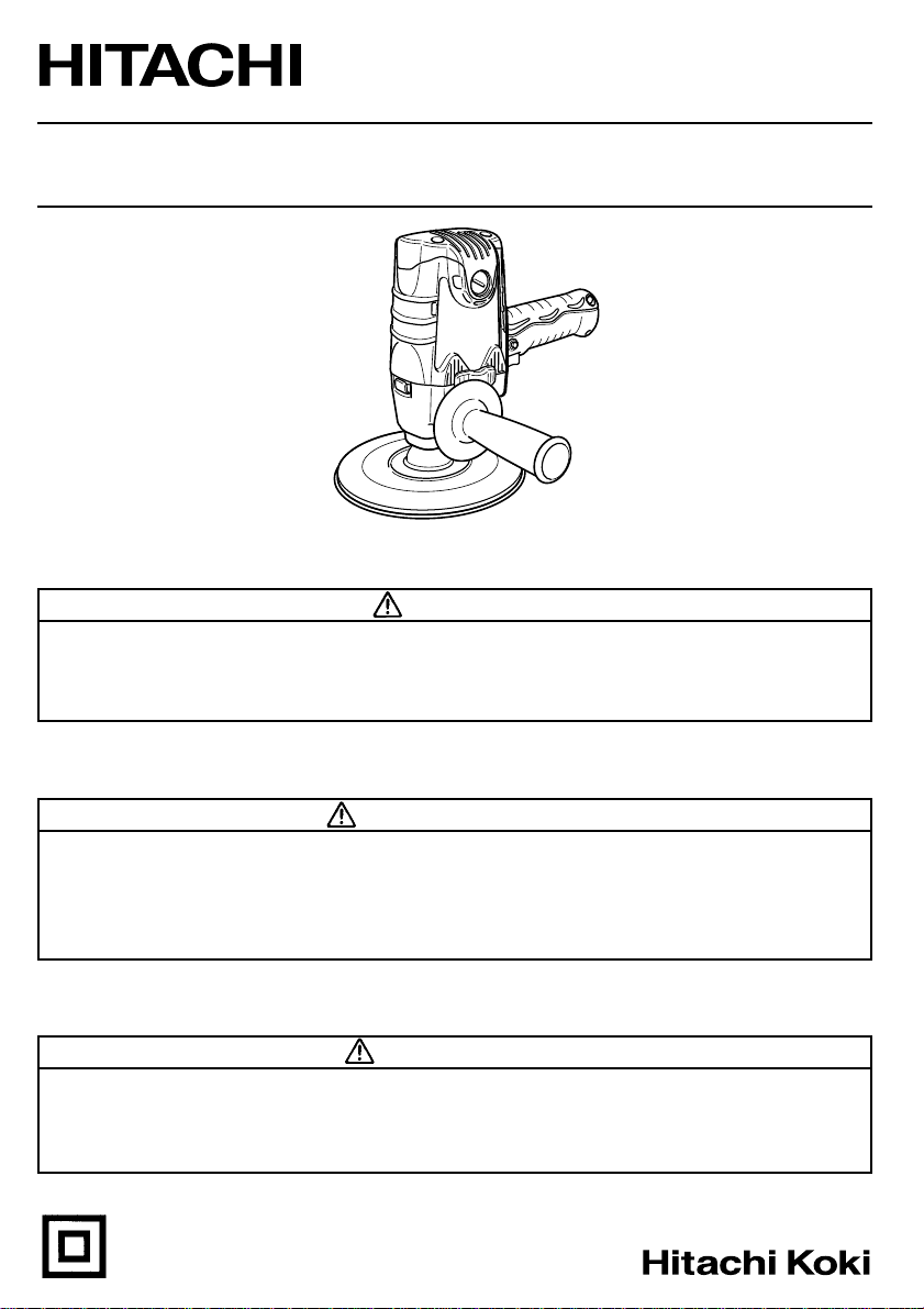
Model Disc Sander
Modèle
Modelo Lijadora de disco
S 18SB
Subleuse/polisseuse à disque
INSTRUCTION MANUAL AND SAFETY INSTRUCTIONS
WARNING
Improper and unsafe use of this power tool can result in death or serious bodily injury!
This manual contains important information about product safety. Please read and
understand this manual before operating the power tool. Please keep this manual
available for others before they use the power tool.
MODE D’EMPLOI ET INSTRUCTIONS DE SECURITE
AVERTISSEMENT
Une utilisation incorrecte et dangereuse de cet outil motorisé peut entraîner la mort ou
de sérieuses blessures corporelles!
Ce mode d’emploi contient d’importantes informations à propos de la sécurité de ce
produit. Prière de lire et de comprendre ce mode d’emploi avant d’utiliser l’outil
motorisé. Garder ce mode d’emploi à la disponibilité des autres utilisateurs avant qu’ils
utilisent l’outil motorisé.
MANUAL DE INSTRUCCIONES E INSTRUCCIONES DE SEGURIDAD
¡La utilización inapropiada e insegura de esta herramienta eléctrica puede resultar en
lesiones serias o en la muerte!
Este manual contiene información importante sobre la seguridad del producto. Lea y
comprenda este manual antes de utilizar la herramienta eléctrica. Guarde este manual
para que puedan leerlo otras personas antes de que utilicen la herramienta eléctrica.
DOUBLE INSULATION
DOUBLE ISOLATION
AISLAMIENTO DOBLE
ADVERTENCIA
Page 2

English
IMPORTANT SAFETY INFORMATION.... 3
MEANINGS OF SIGNAL WORDS.......... 3
SAFETY ................................................... 4
GENERAL SAFETY RULES................. 4
SPECIFIC SAFETY RULES AND SYMBOLS
DOUBLE INSULATION FOR SAFER
OPERATION................................... 8
FUNCTIONAL DESCRIPTION ................ 9
NAME OF PARTS................................ 9
SPECIFICATIONS ................................ 9
CONTENTS
Page
..... 6
Page
ASSEMBLY AND OPERATION ............ 10
APPLICATIONS .................................10
PRIOR TO OPERATION..................... 10
DISC SANDER OPERATION ............. 11
SANDING DISC ASSEMBLY AND
DISASSEMBLY ............................ 12
MAINTENANCE AND INSPECTION .... 13
ACCESSORIES...................................... 14
STANDARD ACCESSORIES ............. 14
PARTS LIST .......................................... 41
Français
INFORMATIONS IMPORTANTES
DE SÉCURITÉ.................................. 15
SIGNIFICATION DES MOTS
D’AVERTISSEMENT ....................... 15
SECURITE .............................................16
CONSIGNES DE SÉCURITÉ GÉNÉRALES...
REGLES DE SECURITE SPECIFIQUES ET SYMBOLES
DOUBLE ISOLATION POUR UN
FONCTIONNEMENT PLUS SUR
DESCRIPTION FONCTIONNELLE ........ 22
NOM DES PARTIES ..........................22
SPECIFICATIONS .............................. 22
Español
INFORMACIÓN IMPORTANTE SOBRE
SEGURIDAD.................................... 28
SIGNIFICADO DE LAS PALABRAS DE
SEÑALIZACIÓN ..............................28
SEGURIDAD .........................................29
NORMAS GENERALES DE SEGURIDAD
NORMAS Y SÍMBOLOS ESPECÍFICOS DE SEGURIDAD
AISLAMIENTO DOBLE PARA OFRECER UNA
OPERACIÓN MÁS SEGURA
DESCRIPCIÓN FUNCIONAL ................ 35
NOMENCLATURA ............................ 35
ESPECIFICACIONES ......................... 35
TABLE DES MATIERES
Page
ASSEMBLAGE ET FONCTIONNEMENT
16
.18
ENTRETIEN ET INSPECTION............... 26
...... 21
ACCESOIRES ........................................ 27
LISTE DES PIECES ............................... 41
ÍNDICE
Página
MONTAJE Y OPERACIÓN ...................36
.. 29
.... 31
................ 34
MANTENIMIENTO E INSPECCIÓN .....39
ACCESORIOS ....................................... 40
LISTA DE PIEZAS .................................41
Page
.... 23
UTILISATIONS .................................. 23
AVANT L’UTILISATION .................... 23
UTILISATION DE LA SUBLEUSE/
POLISSEUSE À DISQUE ............. 24
ASSEMBLAGE ET DESASSEMBLAGE
DE LA DISQUE DE PONCAGE
ACCESSOIRES STANDARD ............. 27
APLICACIONES ................................. 36
ANTES DE LA OPERACIÓN.............. 36
OPERACIÓN DE LA LIJADORA DE DISCO ...
MONTAJE Y DESMONTAJE DE
LA DISCO LIJADOR.....................38
ACCESORIOS ESTÁNDAR ............... 40
......... 25
Página
37
Page 3

English
IMPORTANT SAFETY INFORMATION
Read and understand all of the safety precautions, warnings and operating instructions in
the Instruction Manual before operating or maintaining this power tool.
Most accidents that result from power tool operation and maintenance are caused by the
failure to observe basic safety rules or precautions. An accident can often be avoided by
recognizing a potentially hazardous situation before it occurs, and by observing appropriate
safety procedures.
Basic safety precautions are outlined in the “SAFETY” section of this Instruction Manual
and in the sections which contain the operation and maintenance instructions.
Hazards that must be avoided to prevent bodily injury or machine damage are identified by
WARNINGS on the power tool and in this Instruction Manual.
NEVER use this power tool in a manner that has not been specifically recommended by
HITACHI.
MEANINGS OF SIGNAL WORDS
WARNING indicates a potentially hazardous situations which, if ignored, could result in
death or serious injury.
CAUTION indicates a potentially hazardous situations which, if not avoided, may result in
minor or moderate injury, or may cause machine damage.
NOTE emphasizes essential information.
3
Page 4

English
SAFETY
GENERAL SAFETY RULES
WARNING: Read all instructions
Failure to follow all instructions listed below may result in electric shock,
fire and/or serious injury.
The term “power tool” in all of the warnings listed below refers to your
mains-operated (corded) power tool or battery-operated (cordless)
power tool.
SAVE THESE INSTRUCTIONS
1) Work area safety
a) Keep work area clean and well lit.
Cluttered or dark areas invite accidents.
b) Do not operate power tools in explosive atmospheres, such as in the presence of
flammable liquids, gases or dust.
Power tools create sparks which may ignite the dust of fumes.
c) Keep children and bystanders away while operating a power tool.
Distractions can cause you to lose control.
2) Electrical safety
a) Power tool plugs must match the outlet.
Never modify the plug in any way.
Do not use any adapter plugs with earthed (grounded) power tools.
Unmodified plugs and matching outlets will reduce risk of electric shock.
b) Avoid body contact with earthed or grounded surfaces such as pipes, radiators,
ranges and refrigerators.
There is an increased risk of electric shock if your body is earthed or grounded.
c) Do not expose power tools to rain or wet conditions.
Water entering a power tool will increase the risk of electric shock.
d) Do not abuse the cord. Never use the cord for carrying, pulling or unplugging the
power tool.
Keep cord away from heat, oil, sharp edges or moving parts.
Damaged or entangled cords increase the risk of electric shock.
e) When operating a power tool outdoors, use an extension cord suitable for outdoor
use.
Use of a cord suitable for outdoor use reduces the risk of electric shock.
3) Personal safety
a) Stay alert, watch what you are doing and use common sense when operating a
power tool.
Do not use a power tool while you are tired or under the influence of drugs, alcohol
or medication.
A moment of inattention while operating power tools may result in serious personal
injury.
4
Page 5

b) Use safety equipment. Always wear eye protection.
Safety equipment such as dust mask, non-skid safety shoes, hard hat, or hearing
protection used for appropriate conditions will reduce personal injuries.
c) Avoid accidental starting. Ensure the switch is in the off position before plugging
in.
Carrying power tools with your finger on the switch or plugging in power tools that
have the switch on invites accidents.
d) Remove any adjusting key or wrench before turning the power tool on.
A wrench or a key left attached to a rotating part of the power tool may result in
personal injury.
e) Do not overreach. Keep proper footing and balance at all times.
This enables better control of the power tool in unexpected situations.
f) Dress properly. Do not wear loose clothing or jewellery. Keep your hair, clothing
and gloves away from moving parts.
Loose clothes, jewellery or long hair can be caught in moving parts.
g) If devices are provided for the connection of dust extraction and collection facilities,
ensure these are connected and properly used.
Use of these devices can reduce dust-related hazards.
4) Power tool use and care
a) Do not force the power tool. Use the correct power tool for your application.
The correct power tool will do the job better and safer at the rate for which it was
designed.
b) Do not use the power tool if the switch does not turn it on and off.
Any power tool that cannot be controlled with the switch is dangerous and must be
repaired.
c) Disconnect the plug from the power source and/or the battery pack from the power
toll before making any adjustments, changing accessories, or storing power tools.
Such preventive safety measures reduce the risk of starting the power tool
accidentally.
d) Store idle power tools out of the reach of children and do not allow persons
unfamiliar with the power tool or these instructions to operate the power tool.
Power tools are dangerous in the hands of untrained users.
e) Maintain power tools. Check for misalignment or binding of moving parts, breakage
of parts and any other condition that may affect the power tools operation.
If damaged, have the power tool repaired before use.
Many accidents are caused by poorly maintained power tools.
f) Keep cutting tools sharp and clean.
Properly maintained cutting tools with sharp cutting edges are less likely to bind
and are easier to control.
g) Use the power tool, accessories and tool bits etc., in accordance with these
instructions and in the manner intended for the particular type of power tool,
taking into account the working conditions and the work to be performed.
Use of the power tool for operations different from intended could result in a
hazardous situation.
English
5
Page 6
English
5) Service
a) Have your power tool serviced by a qualified repair person using only identical
replacement parts.
This will ensure that the safety of the power tool is maintained.
–WARNING– To reduce the risk of injury, user must read instruction manual.
SPECIFIC SAFETY RULES AND SYMBOLS
1. Accessories must be rated for at least the speed recommended on the tool warning
label. Accessories running over rated speed can fly apart and cause injury.
2. Hold tools by insulated gripping surfaces when performing an operation where the
cutting tool may contact hidden wiring or its own cord. Contact with a “live” wire will
make exposed metal parts of the tool “live” and shock the operator.
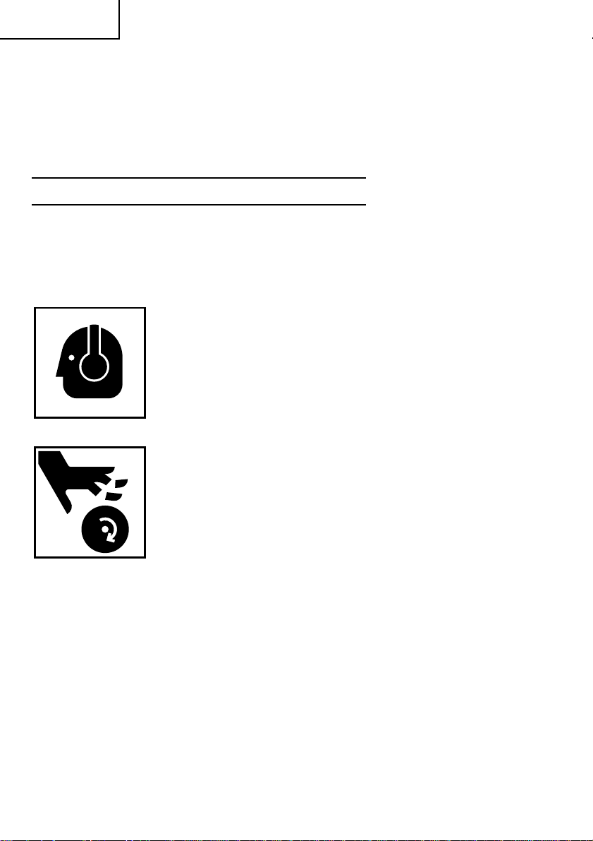
3. ALWAYS wear ear protectors when using the tool for extended periods.
Prolonged exposure to high intensity noise can cause hearing loss.
4. NEVER touch moving parts.
NEVER place your hands, fingers or other body parts near the tool’s
moving parts.
5. NEVER operate without all guards in place.
NEVER operate this tool without all guards or safety features in place and in proper
working order. If maintenance or servicing requires the removal of a guard or safety
feature, be sure to replace the guard or safety feature before resuming operation of the
tool.
6. Use right tool.
Don’t force small tool or attachment to do the job of a heavy-duty tool.
Don’t use tool for purpose not intended —for example— don’t use circular saw for
cutting tree limbs or logs.
7. NEVER use a power tool for applications other than those specified.
NEVER use a power tool for applications other than those specified in the Instruction
Manual.
8. Handle tool correctly.
Operate the tool according to the instructions provided herein. Do not drop or throw
the tool. NEVER allow the tool to be operated by children, individuals unfamiliar with
its operation or unauthorized personnel.
6
Page 7
English
9. Keep all screws, bolts and covers tightly in place.
Keep all screws, bolts, and plates tightly mounted. Check their condition periodically.
10. Do not use power tools if the plastic housing or handle is cracked.
Cracks in the tool’s housing or handle can lead to electric shock. Such tools should not
be used until repaired.
11. Blades and accessories must be securely mounted to the tool.
Prevent potential injuries to yourself or others. Blades, cutting implements and
accessories which have been mounted to the tool should be secure and tight.
12. Keep motor air vent clean.
The tool’s motor air vent must be kept clean so that air can freely flow at all times.
Check for dust build-up frequently.
13. Operate power tools at the rated voltage.
Operate the power tool at voltages specified on its nameplate.
If using the power tool at a higher voltage than the rated voltage, it will result in
abnormally fast motor revolution and may damage the unit and the motor may burn
out.
14. NEVER use a tool which is defective or operating abnormally.
If the tool appears to be operating unusually, making strange noises, or otherwise
appears defective, stop using it immediately and arrange for repairs by a Hitachi
authorized service center.
15. NEVER leave tool running unattended. Turn power off.
Don’t leave tool until it comes to a complete stop.
16. Carefully handle power tools.
Should a power tool be dropped or struck against hard materials inadvertently, it may
be deformed, cracked, or damaged.
17. Do not wipe plastic parts with solvent.
Solvents such as gasoline, thinner benzine, carbon tetrachloride, and alcohol may
damage and crack plastic parts. Do not wipe them with such solvents.
Wipe plastic parts with a soft cloth lightly dampened with soapy water and dry
thoroughly.
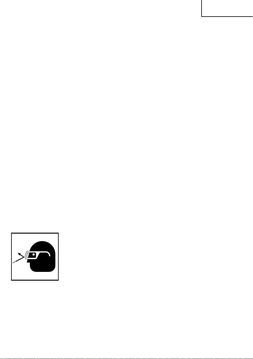
18. ALWAYS wear eye protection that meets the requirement of the latest revision of ANSI
Standard Z87.1.
19. ALWAYS wear a mask or respirator to protect yourself from dust or potentially harmful
particles generated during the operation.
20. NEVER place hands or body parts near the accessories attached to the sanding disc
during operation.
21. NEVER use accessories which are broken or deformed or worn away.
22. NEVER use the sanding disc in places where the sparks generated by the sanding disc
can cause explosion, such as where flammable materials or gases are present.
23. NEVER push in the lock lever while the spindle is running.
24. ALWAYS firmly grip the body handle and side handle while operating the sanding disc.
7
Page 8

English
25. ALWAYS follow the instructions contained in this manual when replacing the
accessories.
26. NEVER leave the revolving tool unattended on the floor.
27. NEVER mount a depressed center wheel on this tool and attempt to use it as a disc
grinder.
28. Definitions for symbols used on this tool
V ............ volts
Hz .......... hertz
A............amperes
no .......... no load speed
W...........watt
...........Class II Construction
---/min ... revolutions per minute
DOUBLE INSULATION FOR SAFER OPERATION
To ensure safer operation of this power tool, HITACHI has adopted a double insulation
design. “Double insulation “ means that two physically separated insulation systems have
been used to insulate the electrically conductive materials connected to the power supply
from the outer frame handled by the operator. Either the symbol “
insulation” appear on the power tool or on the nameplate.
Although this system has no external grounding, you must still follow the normal electrical
safety precautions given in this Instruction Manual, including not using the power tool in
wet environments.
To keep the double insulation system effective, follow these precautions:
䡬 Only HITACHI AUTHORIZED SERVICE CENTER should disassemble or assemble this
power tool, and only genuine HITACHI replacement parts should be installed.
䡬 Clean the exterior of the power tool only with a soft cloth moistened with soapy water,
and dry thoroughly.
Never use solvents, gasoline or thinners on plastic components; otherwise the plastic
may dissolve.
” or the words “Double
SAVE THESE INSTRUCTIONS
AND
MAKE THEM AVAILABLE TO
OTHER USERS AND OWNERS
OF THIS TOOL!
8
Page 9
English
FUNCTIONAL DESCRIPTION
NOTE:
The information contained in this Instruction Manual is designed to assist you in the
safe operation and maintenance of the power tool.
Some illustrations in this Instruction Manual may show details or attachments that differ
from those on your own power tool.
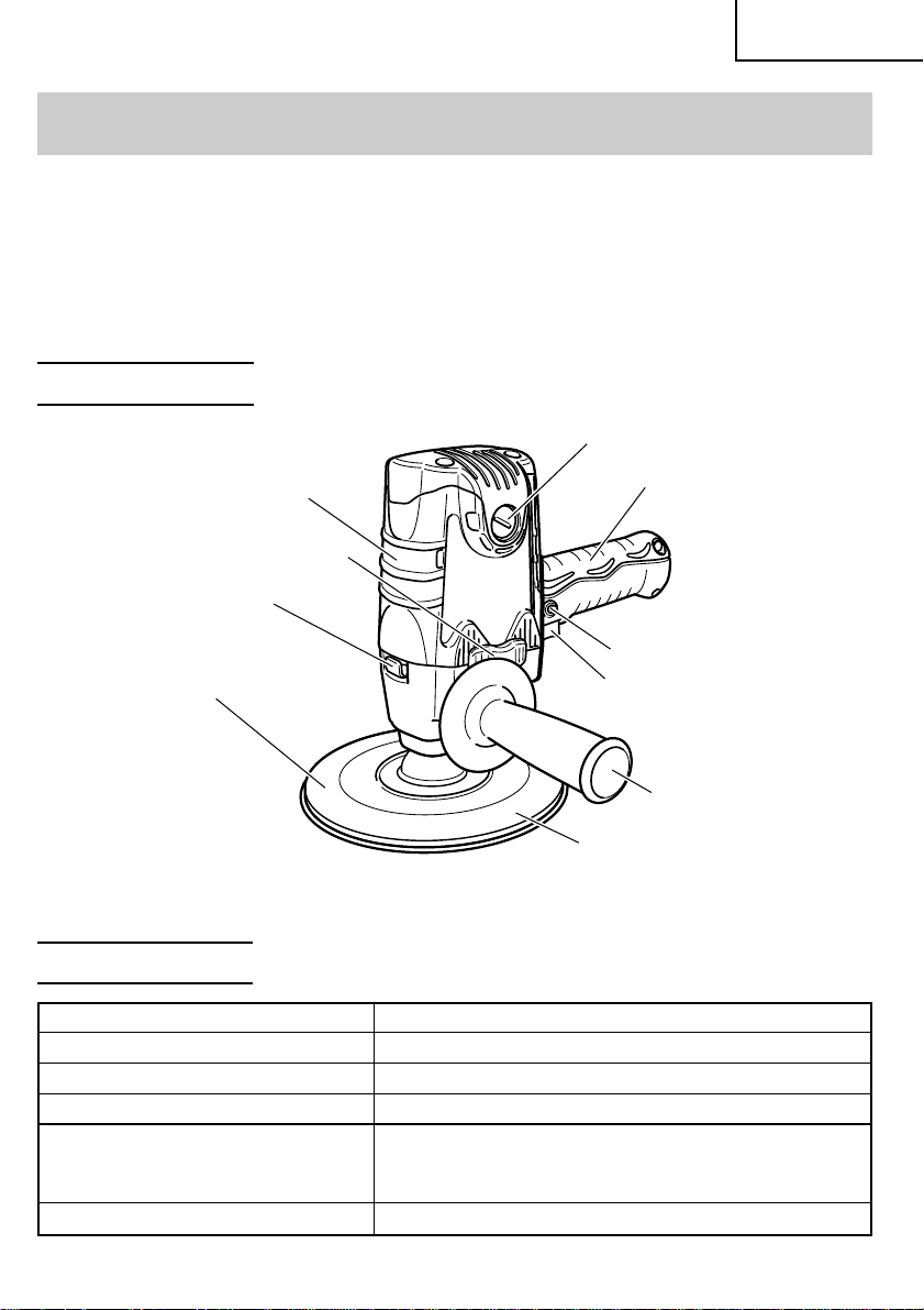
NAME OF PARTS
Brush cap
Housing
Air cover
Lock lever
Rubber pad
Fig. 1
Handle
Locking button
Switch trigger
Side handle
Sanding disc
SPECIFICATIONS
Motor Single-Phase Series Commutator Motor
Power Source Single-Phase 120V AC 60 Hz
Current 6.2 A
No-Load Speed 4,500/min
Sanding Disc Size:
external diam. 7” (180 mm)
hole diam. 7/8” (22 mm)
Weight (only main body) 4.4 lbs (2.0 kg)
9
Page 10

English
ASSEMBLY AND OPERATION
APPLICATIONS
䡬 Sanding metal surfaces.
䡬 Preliminary sanding of metal surfaces before painting, rust removal, removing old paint
before repainting.
䡬 Finishing woodwork, correcting projections of timbers from joints or assemblies.
䡬 Preliminary sanding of wood surfaces before applying paint.
PRIOR TO OPERATION
1. Power source
Ensure that the power source to be utilized conforms to the power source requirements
specified on the product nameplate.
2. Power switch
Ensure that the switch is in the OFF position. If the plug is connected to a receptacle
while the switch is in the ON position, the power tool will start operating immediately
and can cause serious injury.
3. Extension cord
When the work area is far away from the power source, use an extension cord of
sufficient thickness and rated capacity. The extension cord should be kept as short as
practicable.
WARNING: Damaged cord must be replaced or repaired.
4. Check the receptacle.
If the receptacle only loosely accepts the plug, the receptacle must be repaired. Contact
a licensed electrician to make appropriate repairs.
If such a fautly receptacle is used, it may cause overheating, resulting in a serious hazard.
5. Check your working environment.
Ensure the following before operation;
䡬 No flammable gas, liquid, or object at worksite.
䡬 Grinding thin steel sheet may cause a high booming sound.
In this case, place a rubber mat under the workpiece.
䡬 Take appropriate noise preventive measures to prevent adverse affects on the
environment by electrical noise.
䡬 Clear the area of children or unauthorized personnel.
6. Check mounting of the sanding disc.
Check that sanding disc is mounted under the specified condition and is firmly clamped.
For details, refer to the item “SANDING DISC ASSEMBLY AND DISASSEMBLY”.
7. Fixing the side handle.
Screw the side handle into the housing.
8. Check the lock lever.
Make sure that the lock lever is disengaged by pushing the lock lever two or three
times before turning on the disc sander (Fig. 4).
10
Page 11
English
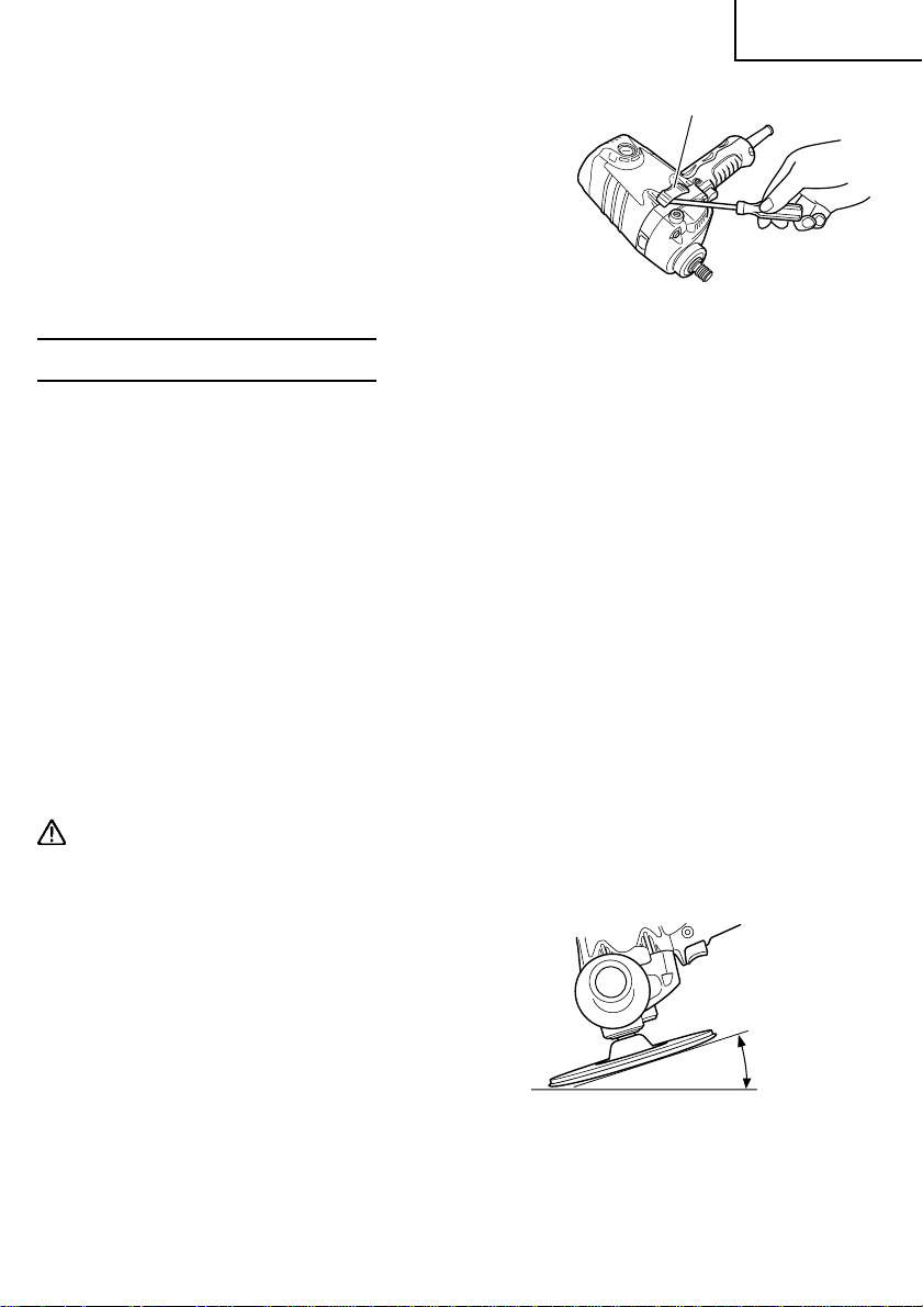
9. Installing the air cover
Install the air cover on the air vent on the
side where the side handle is attached to
divert the cooling air flow of the motor
during operation as much as possible.
Hook tab of the air cover to the air vent and
push in the tab when installing. Use a
screwdriver etc. to pull as shown in Fig. 2
when removing.
Air cover
Fig. 2
DISC SANDER OPERATION
1. Hold the disc sander firmly by its body hadle and side handle (Fig. 1).
The disc sander produces a counterforce which must be controlled by firmly holding
onto the disc sander.
2. Switch operation
This enables the disc sander always to be controlled with the hand gripping the machine
for maximum safety during grinding operations.
<Intermittent use>
Switch ON: Press the switch trigger.
Switch OFF: Release the switch trigger.
<Continuous use>
Switch ON: Press the switch trigger. The switch trigger is locked by pushing on
the locking button.
Switch OFF: Press and release the switch trigger.
3. Use light grinding pressure.
There is no need to press hard when grinding. Usually the disc sander’s own weight is
sufficient for the surface to be ground.
CAUTION: Do not press the disc sander forcibly against the surface to be ground. Heavy
pressure can damage the surface being ground or damage the disc sander’s
motor.
4. Use proper grinding angle.
Use the disc sander by lifting 15° to 30°, as
shown in Fig. 3.
5. Adjust operation to desired finish.
For a fine finish, decrease pressure by lifting
slightly. Grind slowly and at the appropriate
speed.
Fig. 3
15° – 30°
11
Page 12
English
6. Precaution after use
CAUTION: Do not lay the disc sander down immediately after using on a place where
there are many shavings, much dirt and dust until it has completely stopped
revolving.
If the disc sander is laid down with the sanding disc turned downward before
it has completely stopped revolving, there is a risk that the material may be
damaged and the disc sander may run wild, resulting in injury.
SANDING DISC ASSEMBLY AND DISASSEMBLY
WARNING: Never attempt to assemble or disassemble the sanding disc while the
disc sander is capable of being turned “ON”.
Be sure power switch is in the “OFF” position and the electrical cord
has been disconnected from the receptacle.
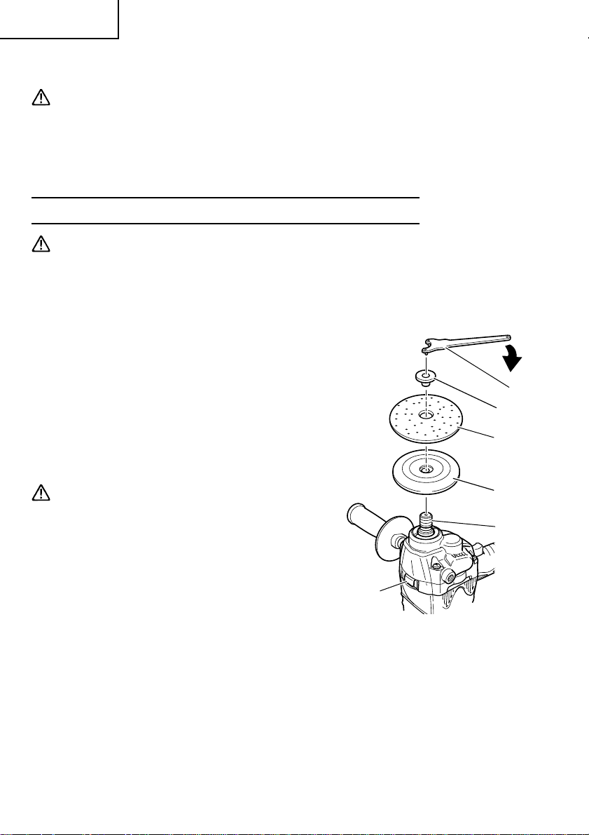
1. Assembling (Fig. 4)
(1) Turn the disc sander upsidedown so that
the spindle is facing upward.
(2) Attach washer nut, rubber pad and sanding
disc on the spindle, in that order.
(3) While pushing the lock lever with one hand,
lock the spindle by turning the rubber pad
slowly with the other hand.
Tighten the washer nut by using the
supplied wrench.
Wrench
Washer nut
Sanding disc
Tighten
CAUTION:
䢇 Tighten the washer nut securely and
confirm that the rubber pad and sanding
disc does not wobble.
䢇 After releasing the lock lever, check to be
sure that it has returned to its normal
position.
2. Disassembling
To remove the sanding disc, follow the
above-mentioned procedure in reverse
order.
12
Rubber pad
Spindle
Lock lever
Fig. 4
Page 13
English
43
MAINTENANCE AND INSPECTION
WARNING: Be sure to switch power OFF and disconnect the plug from the
receptacle during maintenance and inspection.
1. Inspecting the screws
Regularly inspect all screws and ensure that they are fully tightened. Should any of the
screws be loosened, retighten them immediately.
WARNING: Using this disc sander with loosened screws is extremely dangerous.
2. Confirm that there is no damage in the cord and
the housing, etc.
Furthermore, confirm that there is no abnormality in
the activation of the switch.
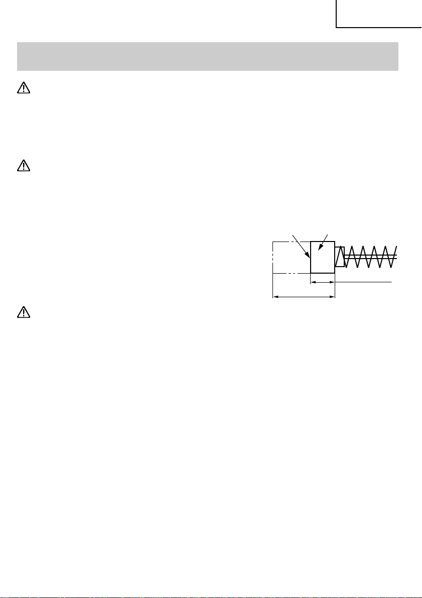
3. Inspecting the carbon brushes (Fig. 5)
The motor employs carbon brushes which are
consumable parts. Replace the carbon brush with a
new one when it becomes worn to its wear limit.
Always keep carbon brushes clean and ensure that
they slide freely within the brush holders.
Wear limit
0.67” (17 mm)
No. of carbon
brush
0.24” (6 mm)
CAUTION: Using this disc sander with a carbon brush
which is worn in excess of the wear limit
will damage the motor.
NOTE: Use HITACHI carbon brush No. 43 indicated in Fig. 5.
䡬 Replacing carbon brushes:
Remove the brush caps (Fig. 1) with a slotted screwdriver. The carbon brushes can
then be easily removed.
Fig. 5
4. Service and repairs
All quality power tools will eventually require servicing or replacement of parts because
of wear from normal use. To assure that only authorized replacement parts will be
used, all service and repairs must be performed by a HITACHI AUTHORIZED SERVICE
CENTER, ONLY.
5. Service parts list
A: Item No.
B: Code No.
C: No. Used
D: Remarks
13
Page 14

English
CAUTION: Repair, modification and inspection of Hitachi Power Tools must be carried
out by a Hitachi Authorized Service Center.
This Parts List will be helpful if presented with the tool to the Hitachi
Authorized Service Center when requesting repair or other maintenance. In
the operation and maintenance of power tools, the safety regulations and
standards prescribed in each country must be observed.
MODIFICATIONS:
Hitachi Power Tools are constantly being improved and modified to incorporate the
latest technological advancements.
Accordingly, some parts (i.e. code numbers and/or design) may be changed without
prior notice.
ACCESSORIES
WARNING: ALWAYS use Only authorized HITACHI replacement parts and
accessories. Never use replacement parts or accessories which are not
intended for use with this tool. Contact HITACHI if you are not sure
whether it is safe to use a particular replacement part or accessory
with your tool.
The use of any other attachment or accessory can be dangerous and
could cause injury or mechanical damage.
NOTE:
Accessories are subject to change without any obligation on the part of the HITACHI.
STANDARD ACCESSORIES
䡬 7” (180 mm) Sanding disc (Grain size: P50) (Code No. 314090).....................................1
䡬 Rubber pad (Code No. 953255) .........................................................................................1
䡬 Wrench (Code No. 937913Z).............................................................................................. 1
䡬 Side handle (Code No. 937089) ......................................................................................... 1
NOTE:
Specifications are subject to change without any obligation on the part of the HITACHI.
14
Page 15

Français
INFORMATIONS IMPORTANTES DE SÉCURITÉ
Lire et comprendre toutes les précautions de sécurité, les avertissements et les instructions
de fonctionnement dans ce mode d’emploi avant d’utiliser ou d’entretenir cet outil motorisé.
La plupart des accidents causés lors de l’utilisation ou de l’entretien de l’outil motorisé
proviennent d’un non respect des règles ou précautions de base de sécurité. Un accident
peut la plupart du temps être évité si l’on reconnaît une situation de danger potentiel avant
qu’elle ne se produise, et en observant les procédures de sécurité appropriées.
Les précautions de base de sécurité sont mises en évidence dans la section “SECURITE”
de ce mode d’emploi et dans les sections qui contiennent les instructions de fonctionnement
et d’entretien.
Les dangers qui doivent être évités pour prévenir des blessures corporelles ou un
endommagement de la machine sont identifiés par AVERTISSEMENTS sur l’outil motorisé
et dans ce mode d’emploi.
NE JAMAIS utiliser cet outil motorisé d’une manière qui n’est pas spécifiquement
recommandée par HITACHI.
SIGNIFICATION DES MOTS D’AVERTISSEMENT
AVERTISSEMENT indique des situations potentiellement dangereuses qui, si elles sont
ignorées, pourraient entraîner la mort ou de sérieuses blessures.
PRECAUTION indique des situations dangereuses potentilles qui, si elles ne sont pas évitées,
peuvent entraîner de mineures et légères blessures ou endommager la machine.
REMARQUE met en relief des informations essentielles.
15
Page 16

Français
SECURITE
CONSIGNES DE SÉCURITÉ GÉNÉRALES
AVERTISSEMENT : Lire toutes les instructions
Tout manquement à observer ces instructions peut engendrer
des chocs électriques, des incendies et/ou des blessures
graves.
Le terme “outil électrique” qui figure dans l'ensemble des
avertissements ci-dessous se réfère aux outils électriques
(câblé) ou aux outils à piles (sans fil).
CONSERVER CES INSTRUCTIONS
1) Sécurité de l’aire de travail
a) Maintenir l'aire de travail propre et bien éclairée.
Les endroits encombrés ou sombres sont propices aux accidents.
b) Ne pas utiliser d'outils électriques en présence de liquides, gaz ou poussière
inflammables, au risque de provoquer une explosion.
Les outils électriques créent des étincelles susceptibles d'enflammer la poussière.
c) Ne pas laisser les enfants et les visiteurs s'approcher de vous lorsque vous utiliser
un outil électrique.
Les distractions peuvent faire perdre le contrôle.
2) Sécurité électrique
a) Les prises de l'outil électrique doivent correspondre à la prise secteur.
Ne jamais modifier la prise.
Ne pas utiliser d'adaptateurs avec les outils électriques mis à la masse.
Les prises non modifiées et les prises secteurs correspondantes réduisent les risques
de choc électrique.
b) Eviter tout contact avec les surfaces mises à la masse telles que les tuyaux,
radiateurs, bandes et réfrigérateurs.
Le risque de choc électrique est accru en cas de mise à la masse du corps.
c) Ne pas exposer les outils électriques à la pluie ou à des conditions humides.
Si l'eau pénètre dans l'outil, cela augmente les risques de choc électrique.
d) Ne pas utiliser le cordon à tort. Ne jamais utiliser le cordon pour transporter ou
débrancher l'outil électrique.
Maintenir le cordon loin de la chaleur, de l'huile, des bords pointus ou des pièces
mobiles.
Les cordons endommagés ou usés augmentent les risques de choc électrique.
e) En cas d'utilisation d'un outil électrique à l'extérieur, utiliser un cordon de rallonge
adapté à un usage extérieur.
L'utilisation d'un cordon adapté à l'usage extérieur réduit les risques de choc
électrique.
16
Page 17

3) Sécurité personnelle
a) Restez alerte, regarder ce que vous faites et usez de votre bon sens en utilisant un
outil électrique.
Ne pas utiliser d'outil électrique si vous êtes sous l'influence de drogues, d'alcool
ou de médicaments.
Pendant l'utilisation d'outils électrique, un instant d'inattention peut entraîner des
blessures graves.
b) Utiliser des équipements de sécurité. Toujours porter des verres de protection.
L'utilisation d'équipements de sécurité tels que les masques anti-poussière, les
chaussures de sécurité anti-dérapantes, les casques ou les protections auditives
dans des conditions appropriées réduisent les risques de blessures.
c) Eviter les démarrages accidentels. Veiller à ce que l'interrupteur soit en position
d'arrêt avant de brancher l'outil.
Transporter les outils électriques avec le doigt sur l'interrupteur ou brancher les
outils électriques avec l'interrupteur en position de marche peut entraîner des
accidents.
d) Retirer toute clé de sécurité ou clé avant de mettre l'outil électrique en marche.
Laisser une clé ou une clé de sécurité sur une partie mobile de l'outil électrique
peut engendrer des blessures.
e) Ne pas trop se pencher. Toujours garder une bonne assise et un bon équilibre
pendant le travail.
Cela permet un meilleur contrôle de l'outil électrique dans des situations
imprévisibles.
f) Porter des vêtements adéquats. Ne pas porter de vêtements amples ni de bijoux.
Maintenir les cheveux, les vêtements et les gants loin des pièces mobiles.
Les vêtements amples ou les cheveux longs peuvent se prendre dans les pièces
mobiles.
g) En cas de dispositifs destinés au raccordement d'installations d'extraction et de
recueil de la poussière, veiller à ce qu'ils soient correctement raccordés et utilisés.
L'utilisation de ces dispositifs peut réduire les dangers associés à la poussière.
4) Utilisation et entretien d'un outil électrique
a) Ne pas forcer sur l'outil électrique. Utiliser l'outil électrique adapté à vos travaux.
Le bon outil électrique fera le travail mieux et en toute sécurité au régime pour
lequel il a été conçu.
b) Ne pas utiliser l'outil électrique si l'interrupteur ne le met pas en position de marche
et d'arrêt.
Tout outil ne pouvant être contrôlé par l'interrupteur est dangereux et doit être
réparé.
c) Débrancher la prise ou retirer la batterie avant de procéder à des réglages, au
remplacement des accessoires ou au stockage des outils électriques.
Ces mesures préventives de sécurité réduisent les risques de démarrage accidentel
de l'outil électrique.
d) Stockez les outils électriques inutilisés hors de la portée des enfants et ne pas
laisser des personnes non familiarisées avec l'outil ou ces instructions utiliser l'outil
électrique.
Les outils électriques sont dangereux entre les mains d'utilisateurs non habilités.
e) Entretenir les outils électriques. Vérifier l'absence de mauvais alignement ou d'arrêt,
d'endommagement de pièces ou toute autre condition susceptible d'affecter
l'opération de l'outil.
Français
17
Page 18

Français
Si l'outil est endommagé, le faire réparer avant utilisation.
De nombreux accidents sont dus à des outils mal entretenus.
f) Maintenir les outils coupants aiguisés et propres.
Des outils coupants bien entretenus avec des bords aiguisés sont moins susceptibles
de se coincer et plus simples à contrôler.
g) Utiliser l'outil électrique, les accessoires et les mèches de l'outil, etc. conformément
à ces instructions et de la manière destinée pour le type précis d'outil électrique,
en tenant compte des conditions d'utilisation et du travail à réaliser.
L'utilisation de l'outil électrique pour des opérations différentes de celles pour
lesquelles il a été conçu est dangereuse.
5) Service
a) Faire entretenir l'outil électrique par un technicien habilité à l'aide de pièces de
rechange identiques exclusivement.
Cela garantira le maintien de la sécurité de l'outil électrique.
–PRECAUTION– Pour réduire tout risque de blessure, l’utilisateur doit lire le mode
d’emploi.
REGLES DE SECURITE SPECIFIQUES ET SYMBOLES
1. Les accessories doivent être utilisés à une cadence équivalent au moins à la vitesse de
rotation de la meule telle qu’elle est indiquée sur l’étiquette de mise en garde de l’outil.
En effet, les accessoires qui sont utilisés à une cadence supérieure à la vitesse nominale
risquent d’être projetés aux alentours et de blesser quelqu’un.
2. Tenir les outils par les surfaces de grippage lors de la réalisation d’opérations où l’outil
de coupe risque d’entrer en contact avec des câbles cachés ou son propre cordon. Un
contact avec un fil “sous tension” mettra les parties métalliques de l’outil “sous tension”
et électrocutera l’utilisateur.
3. TOUJOURS porter des protecteurs d’oreille lors de l’utilisation de l’outil pendant de
longues périodes.
Une exposition prolongée à un son de forte intensité peut endommager
l’ouïe de l’utilisateur.
4. NE JAMAIS toucher les parties mobiles.
NE JAMAIS placer ses mains, ses doigts ou toute autre partie de son
corps près des parties mobiles de l’outil.
18
Page 19

Français
5. NE JAMAIS utiliser l’outil sans que tous les dispositifs de sécurité ne soient en place.
NE JAMAIS faire fonctionner cet outil sans que tous les dispositifs et caractéristiques
de sécurité ne soient en place et en état de fonctionnement. Si un entretien ou une
réparation nécessite le retrait d’un dispositif ou d’une caractéristique de sécurité,
s’assurer de bien remettre en place le dispositif ou la caractéristique de sécurité avant
de recommencer à utiliser l’outil.
6. Utiliser l’outil correct.
Ne pas forcer sur un petit outil ou accessoire pour faire le travail d’un outil de grande
puissance. Ne pas utiliser un outil pour un usage pour lequel il n’a pas été prévu : par
exemple, ne pas utiliser une scie circulaire pour couper des branches d’arbre ou des
bûches.
7. NE JAMAIS utiliser un outil motorisé pour des applications autres que celles spécifiées.
NE JAMAIS utiliser un outil motorisé pour des applications autres que celles spécifiées
dans le mode d’emploi.
8. Manipuler l’outil correctement.
Utiliser l’outil de la façon indiquée dans ce mode d’emploi. Ne pas laisser tomber ou
lancer l’outil. NE JAMAIS permettre que l’outil soit utilisé par des enfants, des personnes
non familiarisées avec son fonctionnement ou un personnel non autorisé.
9. Maintenir toutes les vis, tous les boulons et les couvercles fermement en place.
Maintenir toutes les vis, tous les boulons et les couvercles fermement montés. Vérifier
leurs conditions périodiquement.
10. Ne pas utiliser les outils motorisés si le revêtement de plastique ou la poignée est
fendu.
Des fentes dans le revêtement ou la poignée peuvent entraîner une électrocution. De
tels outils ne doivent pas être utilisés avant d’être réparé.
11. Les lames et les accessoires doivent être fermement montés sur l’outil.
Eviter les blessures potentielles personnelles et aux autres. Les lames, les instruments de
coupe et les accessoires qui ont été montés sur l’outil doivent être fixés et serrés fermement.
12. Garder propres les évents d’air du moteur.
Les évents d’air du moteur doivent être maintenus propres de façon que l’air puisse
circuler librement tout le temps. Vérifier les accumulations de poussière fréquemment.
13. Utiliser l’outil motorisé à la tension nominale.
Utiliser l’outil motorisé à la tension spécifiée sur sa plaque signalétique.
Si l’on utilise l’outil motorisé avec une tension supérieure à la tension nominale, il en
résultera une rotation anormalement trop rapide du moteur et cela risque
d’endommager l’outil et le moteur risque de griller.
14. NE JAMAIS utiliser un outil défectueux ou qui fonctionne anormalement.
Si l’outil n’a pas l’air de fonctionner normalement, fait des bruits étranges ou sans cela
paraît défectueux, arrêter de l’utiliser immédiatement et le faire réparer par un centre
de service Hitachi autorisé.
15. NE JAMAIS laisser fonctionner l’outil sans surveillance. Le mettre hors tension.
Ne pas abandonner l’outil avant qu’il ne soit complètement arrêté.
16. Manipuler l’outil motorisé avec précaution.
Si un outil motorisé tombe ou frappe un matériau dur accidentellement, il risque d’être
déformé, fendu ou endommagé.
19
Page 20

Français
17. Ne pas essuyer les parties en plastique avec du solvant.
Les solvants comme l’essence, les diluants, la benzine, le tétrachlorure de carbone et
l’alcool peuvent endommager et fissurer les parties en plastique. Ne pas les essuyer
avec de tels solvants.
Essuyer les parties en plastique avec un chiffon doux légèrement imbibé d’une solution
d’eau savonneuse et sécher minutieusement.
18. TOUJOURS porter des lunettes des protections conformes aux exigences des dernières
révisions du standard ANSI Z87.1.
19. TOUJOURS porter un masque ou un respirateur pour se protéger de la poussière et
des particules dangereuses générées pendant l’opération.
20. NE JAMAIS placer ses mains ou d’autres parties de son corps près des accessoires
fixés sur le disque de verre pendant l’opération.
21. NE JAMAIS utiliser un accessoire cassé, déformé ou usé.
22. NE JAMAIS utiliser le disque de verre dans des endroits où les étincelles générées par
le disque de verre peuvent causer une explosion. Par exemple, en présence de matériaux
inflammables ou de gaz.
23. NE JAMAIS appuyer sur le levier de verrouillage pendant que l’arbre est en train de
tourner.
24. TOUJOURS tenir fermement la poignée principale et la poignée latérale lors de
l’utilisation de le disque de verre.
25. TOUJOURS suivre les instructions contenues dans ce mode d’emploi lors du
remplacement des accessoires.
26. NE JAMAIS poser l’outil sur le sol et s’en éloigner pendant qu’il fonctionne.
27. NE JAMAIS monter de meule à dépression centrale sur l’outil et ne pas tenter de l’utiliser
comme meuleuse d’angle.
28. Définitions pour les symboles utilisés sur cet outil
V ............ volts
Hz .......... hertz
A............ampères
no .......... vitesse sans charge
W...........watt
...........Construction de classe II
---/min ... tours par minute
20
Page 21

Français
DOUBLE ISOLATION POUR UN FONCTIONNEMENT PLUS SUR
Pour assurer un fonctionnement plus sûr de cet outil motorisé, HITACHI a adopté une
conception à double insolation. “Double isolation” signifie que deux systèmes d’isolation
physiquement séparés ont été utilisés pour isoler les matériaux conducteurs d’électricité
connectés à l’outil motorisé à partir du cadre extérieur manipulé par l’utilisateur. Le symbole
“
” ou les mots “Double insulation” (double isolation) apparaissent sur l’outil motorisé
ou sur la plaque signalétique.
Bien que ce système n’ait pas de mise à terre extérieure, il est quand même nécessaire de
suivre les précautions de sécurité électrique données dans ce mode d’emploi, y-compris
de ne pas utiliser l’outil motorisé dans un environnement humide.
Pour garder le système de double isolation effectif, suivre ces précautions :
䡬 Seuls les CENTRES DE SERVICE AUTORISES HITACHI peuvent démonter et remonter
cet outil motorisé et uniquement des pièces de rechange HITACHI garanties d’origine
doivent être utilisées.
䡬 Nettoyer l’extérieur de l’outil motorisé uniquement avec un chiffon doux légèrement
imbibé d’une solution savonneuse et essuyer minutieusement.
Ne jamais utiliser des solvants, de l’essence ou des diluants sur les parties en plastique ;
sinon le plastique risquerait de se dissoudre.
CONSERVER CES INSTRUCTIONS
ET
LES METTRE A LA DISPOSITION
DES AUTRES UTILISATEURS ET
PROPRIETAIRES DE CET OUTIL !
21
Page 22

Français
DESCRIPTION FONCTIONNELLE
REMARQUE:
Les informations contenues dans ce mode d’emploi sont conçues pour assister
l’utilisateur dans une utilisation sans danger et un entretien de l’outil motorisé.
Certaines illustrations dans ce mode d’emploi peuvent montrer des détails ou des
accessoires différents de ceux de l’outil motorisé utilisé.
NOM DES PARTIES
Couvercle du balai
Boîtier
Couvercle d’aération
Levier de blocage
Plateau en caoutchouc
Fig. 1
Poignée
Bouton de blocage
Interrupteur
Poignée latérale
Disque de ponçage
SPECIFICATIONS
Moteur Moteur série monophasé à collecteur
Source d’alimentation Secteur, 120V 60 Hz, monophasé
Courant 6.2 A
Vitesse sans charge 4,500/min.
Dimension du disque de ponçage:
Diamètre extérieut 7” (180 mm)
Diamètre du trou central 7/8” (22 mm)
Poids
(unité principale uniquement)
4.4 lbs (2.0 kg)
22
Page 23

Français
ASSEMBLAGE ET FONCTIONNEMENT
UTILISATIONS
䡬 Ponçage de surfaces métalliques.
䡬 Ponçage préliminaire de surfaces métalliques avant la peinture, retrait de rouille, retrait
des vieilles couches peinture avant l'application d'une nouvelle couche de peinture.
䡬 Finition de pièces en bois, correction des saillies de bois dépassant des raccords ou
des assemblages.
䡬 Ponçage préliminaire de surfaces en bois avant l'application d'une couche de peinture.
AVANT L’UTILISATION
1. Source d’alimentation
S’assurer que la source d’alimentation qui doit être utilisée est conforme à la source
d’alimentation requise spécifiée sur la plaque signalétique du produit.
2. Interrupteur d’alimentation
S’assurer que l’interrupteur est sur la position OFF (arrêt). Si la fiche est connectée sur
une prise alors que l’interrupteur est sur la position ON (marche), l’outil motorisé
démarrera immédiatement risquant de causer de sérieuses blessures.
3. Cordon prolongateur
Quand la zone de travail est éloignée de la source d’alimentation, utiliser un cordon
prolongateur d’épaisseur et de capacité nominale suffisante. Le cordon prolongateur
doit être aussi court que possible.
AVERTISSEMENT: Tout cordon endommagé devra être remplacé ou réparé.
4. Vérifier la prise.
Si la prise reçoit la fiche avec beaucoup de jeu, elle doit être réparée. Contacter un
électricien licencié pour réaliser les réparations nécessaires.
Si une telle prise défectueuse est utilisée, elle peut causer une surchauffe entraînant
des dangers sérieux.
5. Vérifier l’environnement de travail.
S’assurer des points suivants avant d’utiliser l’appareil;
䡬 Il n’y a aucun gaz, liquide ou objet inflammable sur le site de travail.
䡬 Le meulage de fines feuilles de métal peut causer un son très retentissant.
Dans ce cas, placer un matelas de caoutchouc sous la pièce à usiner.
䡬 Prendre les mesures de prévention appropriées pour éviter les effets nuisibles
causés sur l’environnement par les bruits électriques.
䡬 Eloigner de la pièce tous les enfants et le personnel non autorisé.
6. Vérifier l’installation de la disque de ponçage.
Vérifier que le disque de ponçage est monté dans les conditions spécifiées et qu'il est
solidement fixé.
Pour les détails, voir la section “Assemblage et désassemblage du disque de ponçage”.
23
Page 24

Français
7. Mise en place de la poignée latérale.
Visser la poignée latérale dans le logement.
8. Vérifier la broche de verrouillage.
S’assurer que la broche de verrouillage n’est pas engagée appuyant dessus deux ou
trois fois avant de mettre la subleuse/polisseuse à disque en marche. (Fig. 4)
9. Installation du couvercle d’aération
Installez le couvercle d’aération sur l’évent d’aération
sur le côté où la poignée latérale est fixée pour dévier
le flux d’air refroidissant du moteur le plus possible
pendant l’utilisation. Accrochez la languette du
couvercle d’aération à l’évent d’aération et appuyez
sur la languette pendant l’installation. Lors du retrait,
utilisez un tournevis, etc. pour tirer, tel que cela est
indiqué dans la Fig. 2.
Couvercle d’aération
Fig. 2
UTILISATION DE LA SUBLEUSE/POLISSEUSE À DISQUE
1. Maintenir la subleuse/polisseuse à disque fermement par la poignée du corps
et sa poignée secondaire. (Fig. 1)
La subleuse/polisseuse à disque produit une contre-force qui doit être maîtrisée en la
maintenant fermement.
2. Utilisation de l’interrupteur
Il permet à la subleuse/polisseuse à disque d’être toujours commandée avec la main
tenant la machine pour une sésurité maximum pendant les opérations de meulage.
<Utilisation intermittente>
Interrupteur sur ON (marche): Appuyer sur gâchette.
Interrupteur sur OFF (arrêt): Relâcher gâchette.
<Utilisation continue>
Interrupteur sur ON (marche): Appuyer sur la gâchette. La gâchette se bloque en
appuyant sur le bouton de blocage.
Interrupteur sur OFF (arrêt): Appuyer sur gâchette puis le relâcher.
3. Utiliser une légère pression de meulage.
Il n’y a pas besoin d’appuyer fortement sur la subleuse/polisseuse à disque pendant le
meulage. Normalement le propre poids de la subleuse/polisseuse à disque est suffisant
pour la surface à travailler.
PRECAUTION: Ne pas presser avec force la subleuse/polisseuse à disque sur la surface
à rectifier. Une forte pression peut endommager la surface en train
d’être rectifiée et le moteur de la subleuse/polisseuse à disque.
4.
Utiliser un angle de meulage correct.
Utíliser la subleuse/polisseuse à disque en la soulevant
de 15° à 30°, comme montré sur la Fig. 3.
5. Opération d’ajustement pour la finition
souhaitée.
Pour une finition fine, diminuer la pression en
soulevant légèrement la meuleuse.
Meuler doucement et à la vitesse appropriée.
24
Fig. 3
15° – 30°
Page 25

Français
6. Précautions après l’utilisation
PRECAUTION: Ne pas poser la subleuse/polisseuse à disque à en endroit où il y a
beaucoup de copeaux, de saleté et de poussière tout de suite après
l’utilisation tant que l’outil n’est pas complètement arrêté.
Si l’on pose la subleuse/polisseuse à disque avec la disque de ponçage
tournée vers le bas avant qu’elle n’ait complètement cessé de tourner,
le matériau risque d’être endommagé et la subleuse/polisseuse à disque
de tourner sans contrôle, ce qui pourrait provoquer des blessures.
ASSEMBLAGE ET DESASSEMBLAGE DE LA DISQUE DE PONCAGE
AVERTISSEMENT: Ne jamais essayer d’assembler ou de désassembler la disque
de ponçage si la subleuse/polisseuse à disque est en état de
pouvoir être mise en marche.
S’assurer que l’interrupteur d’alimentation est sur la position
“OFF” et que le cordon électrique a été déconnecté de la prise
secteur.
1. Assemblage (Fig. 4)
(1) Mettre la subleuse/polisseuse à disque à
l’envers de façon que l’arbre soit dirigé vers
le haut.
(2) Fixer l’écrou à rondelle, le platesu en
caoutchouc et le disque à poncer sur l’axe,
dans cet ordre.
(3) Tout en appuyant d’une main sur le levier
de blocage, bloquer l’axe en tournant
lentement le plateau de caoutchouc de
l’autre main.
Serrer l’écrou à rondelle à l’aide de la clé
fournie.
PRECAUTION:
䢇 Serrer l’écrou à rondelle à fond et vérifier
que le plateau caoutchouc er la subleuse/
polisseuse à disque ne présentent pas
d’irrégularités de rotation.
䢇 Après avoir libéré le levier de verrouillage,
vérifier qu’il est revenu sur sa position
normale.
Ecrou rondelle
Levier de
blocage
Fig. 4
Serrer
Clef
Disque de
ponçage
Plateau en
caoutchouc
Arbre
2. Désassemblage
Pour retirer la disque de ponçage, suivre la
procédure ci-dessus dans l’ordre inverse.
25
Page 26

Français
43
ENTRETIEN ET INSPECTION
AVERTISSEMENT: S’assurer de mettre l’interrupteur d’alimentation sur la
position OFF et de déconnecter la fiche de la prise secteur
avant l’entretien et l’inspection de la subleuse/polisseuse à
disque.
1. Inspection des vis
Inspecter régulièrement toutes les vis et s’assurer qu’elles sont serrées à fond. Si l’une
des vis était desserrée, la resserrer immédiatement.
AVERTISSEMENT: Utiliser la subleuse/polisseuse à disque avec des vis
desserrées est extrêmement dangereux.
2. Vérifier qu’il n’y a aucun dommage au cordon,
au boîtier, etc.
De plus, vérifier qu’il n’y a pas d’anomalie dans
l’activation de l’interrupteur.
Limite
d’usure
No. du balai
en carbone
3. Inspection des balais en carbone (Fig. 5)
Le moteur utilise des balais en carbone qui sont des
pièces qui s’usent. Remplacer un balai en carbone
par un nouveau quand il est usé jusqu’à sa limite
d’usure. Toujours garder propres les balais en
carbone et s’assurer qu’ils glissent librement à
l’intérieur des porte-balais.
PRECAUTION: Utiliser la subleuse/polisseuse à disque avec un balai en carbone qui
est usé au-delà de la limite d’usure endommagera le moteur.
REMARQUE: Utiliser le balai en carbone HITACHI No. 43 indiqué sur la Fig. 5.
䡬 Remplacement d’un balai en carbone:
Retirer le couvercle du balai (Fig. 1) avec un tournevis plat. Le balai en carbone peut
être alors facilement retiré.
0.67” (17 mm)
0.24” (6 mm)
Fig. 5
4. Entretien et réparation
Tous les outils motorisés de qualité auront éventuellement besoin d’une réparation ou
du remplacement d’une pièce à cause de l’usure normale de l’outil. Pour assurer que
seules des pièces de rechange autorisées seront utilisées, tous les entretiens et les
réparations doivent être effectués uniquement par UN CENTRE DE SERVICE HITACHI
AUTORISE.
5. Liste des pièces de rechange
A: No. élément
B: No. code
C: No. utilisé
D: Remarques
26
Page 27

Français
PRECAUTION: Les réparations, modifications et inspections des outils électriques
Hitachi doivent être confiées à un service après-vente Hitachi agréé.
Il sera utile de présenter cette liste de pièces au service après-vente
Hitachi agréé lorsqu’on apporte un outil nécessitant des réparations
ou tout autre entretien.
Lors de l’utilisation et de l’entretien d’un outil électrique, respecter les
règlements et les normes de sécurité en vigueur dans le pays en
question.
MODIFICATIONS :
Les outils électriques Hitachi sont constamment améliorés et modifiés afin d’incorporer
les tous derniers progrès technologiques.
En conséquence, il est possible que certaines pièces (c.-à-d. no. de code et/ou dessin)
soient modifiées sans avis préalable.
ACCESSOIRES
AVERTISSEMENT: TOUJOURS utiliser UNIQUEMENT des pièces de rechange et
des accessoires HITACHI. NE JAMAIS utiliser de pièce de
rechange ou d’accessoires qui ne sont pas prévus pour être
utilisé avec cet outil. En cas de doute, contacter HITACHI
pour savoir si une pièce de rechange ou un accessoire
particulier peuvent être utilisés en toute sécurité avec votre
outil.
L’utilisation de tout autre attachement ou accessoire peut
être dangereux et peut causer des blessures ou des
dommages mécaniques.
REMARQUE:
Les accessoires sont sujets à changement sans obligation de la part de HITACHI.
ACCESSOIRES STANDARD
䡬 Disque de ponçage de 7” (180 mm) (Taille du grain: P50) (Code No. 314090) ............. 1
䡬 Plateau en caoutchouc (Code No. 953255)....................................................................... 1
䡬 Clef (Code No. 937913Z) ....................................................................................................1
䡬 Poignée latérale (Code No. 937089).................................................................................. 1
REMARQUE:
Les spécifications sont sujettes à modification sans aucune obligation de la part de HITACHI.
27
Page 28

Español
INFORMACIÓN IMPORTANTE SOBRE SEGURIDAD
Antes de utilizar o de realizar cualquier trabajo de mantenimiento de esta herramienta
eléctrica, lea y comprenda todas las precauciones de seguridad, advertencias e instrucciones
de funcionamiento de este Manual de instrucciones.
La mayoría de los accidentes producidos en la operación y el mantenimiento de una
herramienta eléctrica se deben a la falta de observación de las normas o precauciones de
seguridad. Los accidentes normalmente podrán evitarse reconociendo una situación
potencialmente peligrosa a tiempo y siguiendo los procedimientos de seguridad apropiados.
Las precauciones básicas de seguridad se describen en la sección “SEGURIDAD” de este
Manual de instrucciones y en las secciones que contienen las instrucciones de operación y
mantenimiento.
Para evitar lesiones o el daño de la herramienta eléctrica, los riesgos están identificados
con ADVERTENCIAS en dicha herramienta y en este Manual de instrucciones.
NO utilice NUNCA esta herramienta eléctrica de ninguna forma que no esté específicamente
recomendada por HITACHI.
SIGNIFICADO DE LAS PALABRAS DE SEÑALIZACIÓN
ADVERTENCIA indica situaciones potencialmente peligrosas que, si se ignoran, pueden
resultar en la muerte o en lesiones de gravedad.
PRECAUCIÓN indica situaciones potencialmente peligrosas que, de no evitarse, pueden
resultar en lesiones menores o moderadas, o causar daños en la herramienta eléctrica.
NOTA acentúa información esencial.
28
Page 29

SEGURIDAD
NORMAS GENERALES DE SEGURIDAD
ADVERTENCIA: Lea todas las instrucciones
Si no se siguen las instrucciones de abajo podría producirse una
descarga eléctrica, un incendio y/o daños graves.
El término “herramienta eléctrica” en todas las advertencias
indicadas a continuación hace referencia a la herramienta eléctrica
que funciona con la red de suministro (con cable) o a la
herramienta eléctrica que funciona con pilas (sin cable).
CONSERVE ESTAS INSTRUCCIONES
1) Seguridad en el área de trabajo
a) Mantenga la zona de trabajo limpia y bien iluminada.
Las zonas desordenadas o oscuras pueden provocar accidentes.
b) No utilice las herramientas eléctricas en entornos explosivos como, por ejemplo,
en presencia de líquidos inflamables, gases o polvo.
Las herramientas eléctricas crean chispas que pueden hacer que el polvo desprenda
humo.
c) Mantenga a los niños y transeúntes alejados cuando utilice una herramienta
eléctrica.
Las distracciones pueden hacer que pierda el control.
2) Seguridad eléctrica
a) Los enchufes de las herramientas eléctricas tienen que ser adecuados a la toma de
corriente.
No modifique el enchufe.
No utilice enchufes adaptadores con herramientas eléctricas conectadas a tierra.
Si no se modifican los enchufes y se utilizan tomas de corriente adecuadas se
reducirá el riesgo de descarga eléctrica.
b) Evite el contacto corporal con superficies conectadas a tierra como tuberías,
radiadores y frigoríficos.
Hay mayor riesgo de descarga eléctrica si su cuerpo está en contacto con el suelo.
c) No exponga las herramientas eléctricas a la lluvia o a la humedad.
La entrada de agua en una herramienta eléctrica aumentará el riesgo de descarga
eléctrica.
d) No utilice el cable incorrectamente. No utilice el cable para transportar, tirar de la
herramienta eléctrica o desenchufarla.
Mantenga el cable alejado del calor, del aceite, de bordes afilados o piezas móviles.
Los cables dañados o enredados aumentan el riesgo de descarga eléctrica.
e) Cuando utilice una herramienta eléctrica al aire libre, utilice un cable prolongador
adecuado para utilizarse al aire libre.
La utilización de un cable adecuado para usarse al aire libre reduce el riesgo de
descarga eléctrica.
Español
29
Page 30

Español
3) Seguridad personal
a) Esté atento, preste atención a lo que hace y utilice el sentido común cuando utilice
una herramienta eléctrica.
No utilice una herramienta eléctrica cuando esté cansado o esté bajo la influencia
de drogas, alcohol o medicación.
La distracción momentánea cuando utiliza herramientas eléctricas puede dar lugar
a importantes daños personales.
b) Utilice equipo de seguridad. Utilice siempre una protección ocular.
El equipo de seguridad como máscara para el polvo, zapatos de seguridad
antideslizantes, casco o protección para oídos utilizado para condiciones adecuadas
reducirá los daños personales.
c) Evite un inicio accidental. Asegúrese de que el interruptor está en “off” antes de
enchufarlo.
El transporte de herramientas eléctricas con el dedo en el interruptor o el enchufe
de herramientas eléctricas con el interruptor encendido puede provocar accidentes.
d) Retire las llaves de ajuste antes de encender la herramienta eléctrica.
Si se deja una llave en una pieza giratoria de la herramienta eléctrica podrían
producirse daños personales.
e) No se extralimite. Mantenga un equilibrio adecuado en todo momento.
Esto permite un mayor control de la herramienta eléctrica en situaciones
inesperadas.
f) Vístase adecuadamente. No lleve prendas sueltas o joyas. Mantenga el pelo, la
ropa y los guantes alejados de las piezas móviles.
La ropa suelta, las joyas y el pelo largo pueden pillarse en las piezas móviles.
g) Si se proporcionan dispositivos para la conexión de extracción de polvo e
instalaciones de recogida, asegúrese de que están conectados y se utilizan
adecuadamente.
La utilización de estos dispositivos puede reducir los riesgos relacionados con el
polvo.
4) Utilización y mantenimiento de las herramientas eléctricas
a) No fuerce la herramienta eléctrica. Utilice la herramienta eléctrica correcta para su
aplicación.
La herramienta eléctrica correcta trabajará mejor y de forma más segura si se utiliza
a la velocidad para la que fue diseñada.
b) No utilice la herramienta eléctrica si el interruptor no la enciende y apaga.
Las herramientas eléctricas que no pueden controlarse con el interruptor son
peligrosas y deben repararse.
c) Antes de hacer ajustes, cambiar accesorios o almacenar las herramientas eléctricas,
desconecte el enchufe de la fuente eléctrica y/o las baterías de la herramienta.
Estas medidas de seguridad preventivas reducen el riesgo de que la herramienta
eléctrica se ponga en marcha accidentalmente.
d) Guarde las herramientas eléctricas que no se utilicen para que no las cojan los
niños y no permita que utilicen las herramientas eléctricas personas no
familiarizadas con las mismas o con estas instrucciones.
Las herramientas eléctricas son peligrosas si son utilizadas por usuarios sin
formación.
30
Page 31

Español
e) Mantenimiento de las herramientas eléctricas. Compruebe si las piezas móviles
están mal alineadas o unidas, si hay alguna pieza rota u otra condición que pudiera
afectar al funcionamiento de las herramientas eléctricas.
Si la herramienta eléctrica está dañada, llévela a reparar antes de utilizarla.
Se producen muchos accidentes por no realizar un mantenimiento correcto de las
herramientas eléctricas.
f) Mantenga las herramientas de corte afiladas y limpias.
Las herramientas de corte correctamente mantenidas con los bordes de corte
afilados son más fáciles de controlar.
g) Utilice la herramienta eléctrica, los accesorios y las brocas de la herramienta, etc.,
de acuerdo con estas instrucciones y de la manera adecuada para el tipo de
herramienta eléctrica, teniendo en cuenta las condiciones laborales y el trabajo
que se va a realizar.
La utilización de la herramienta eléctrica para operaciones diferentes a pretendidas
podría dar lugar a una situación peligrosa.
5) Revisión
a) Lleve su herramienta a que la revise un experto cualificado que utilice sólo piezas
de repuesto idénticas.
Esto garantizará el mantenimiento de la seguridad de la herramienta eléctrica.
–ADVERTENCIA– Para disminuir el riesgo de lesiones, el usuario debe leer el manual
de instrucciones.
NORMAS Y SÍMBOLOS ESPECÍFICOS DE SEGURIDAD
1. Los accesorios deben tener un valor nominal por lo menos para la velocidad recomendad
en la etiqueta de advertencia de la herramienta. Los accesorios que funcionan a una
velocidad superior a la nominal pueden salir volando y causar daños.
2. Sujete las herramientas por las superficies de empuñadura aisladas cuando realice
una operación en que la herramienta de corte pueda entrar en contacto con cables
ocultos o con su propio cable de alimentación. El contacto con un conductor “activo”
“activará” las partes metálicas de la herramienta y el operador recibirá una descarga
eléctrica.
3. Emplee SIEMPRE protectores auditivos cuando tenga que utilizar la herramienta
durante mucho tiempo.
La exposición prolongada a ruido de gran intensidad puede causar la
pérdida del sentido del oído.
31
Page 32

Español
4. NO toque NUNCA las piezas móviles.
NO coloque NUNCA sus manos, dedos, ni demás partes del cuerpo
cerca de las piezas móviles de la herramienta.
5. NO utilice NUNCA la herramienta sin los protectores colocados en su lugar.
NO utilice NUNCA esta herramienta sin los protectores de seguridad correctamente
instalados. Si el trabajo de mantenimiento o de reparación requiere el desmontaje de
un protector de seguridad, cerciórese de volver a instalarlo antes de utilizar la
herramienta.
6. Utilice la herramienta correcta.
No fuerce herramientas ni accesorios pequeños para realizar un trabajo pesado.
No utilice las herramientas para fines no proyectados, por ejemplo, no utilice esta
amoladora angular para cortar madera.
7. NO utilice NUNCA una herramienta eléctrica para aplicaciones que no sean las
especificadas.
NO utilice NUNCA una herramienta eléctrica para aplicaciones no especificadas en
este Manual de instrucciones.
8. Maneje correctamente la herramienta.
Maneje la herramienta de acuerdo con las instrucciones ofrecidas aquí. No deje caer ni
tire la herramienta. NO permita NUNCA que los niños ni otras personas no autorizadas
ni familiarizadas con la operación de la herramienta utilicen ésta.
9. Mantenga todos los tornillos, pernos, y cubiertas firmemente fijados en su lugar.
Mantenga todos los tornillos, pernos, y cubiertas firmemente montados. Compruebe
periódicamente su condición.
10. No utilice herramientas eléctricas si la carcasa o la empuñadura de plástico está rajada.
Las rajas en la carcasa o en la empuñadura de plástico pueden conducir a descargas
eléctricas. Tales herramientas no deberán utilizarse mientras no se hayan reparado.
11. Las cuchillas y los accesorios deberán montarse con seguridad en la herramienta.
Evite lesiones personales y de otras personas. Las cuchillas, los accesorios de corte, y
demás accesorios montados en la herramienta deberán fijarse con seguridad.
12. Mantenga limpio el conducto de ventilación del motor.
El conducto de ventilación del motor limpio para que el aire pueda circular libremente
en todo momento. Compruebe frecuentemente y limpie el polvo acumulado.
13. Utilice las herramientas eléctricas con la tensión de alimentación nominal.
Utilice las herramientas eléctricas con las tensiones indicadas en sus placas de
características.
La utilización e una herramienta eléctrica con una tensión superior a la nominal podría
resultar en revoluciones anormalmente altas del motor, en el daño de la herramienta,
y en la quemadura del motor.
14. NO utilice NUNCA una herramienta defectuosa o que funcione anormalmente.
Si la herramienta parece que funciona anormalmente, produciendo ruidos extraños,
etc., deje inmediatamente de utilizarla y solicite su arreglo a un centro de reparaciones
autorizado por Hitachi.
32
Page 33

Español
15. NO deje NUNCA la herramienta en funcionamiento desatendida. Desconecte su
alimentación.
No deje sola la herramientas hasta mientras no se haya parado completamente.
16. Maneje con cuidado las herramientas eléctricas.
Si una herramienta eléctrica se ha caído o ha chocado inadvertidamente contra
materiales duros, es posible que se haya deformado, rajado, o dañado.
17. No limpie las partes de plástico con disolvente.
Los disolventes, como gasolina, diluidor de pintura, bencina, tetracloruro de carbono,
y alcohol pueden dañar o rajar las partes de plástico. No las limpie con tales disolventes.
Limpie las partes de plástico con un paño suave ligeramente humedecido en agua
jabonosa y después séquelas bien.
18. SIEMPRE utilice protección para los ojos que satisfaga los requisitos de la última versión
de la norma Z87.1 de ANSI.
19. SIEMPRE utilice una mascarilla para protegerse contra el polvo o las partículas
potencialmente dañinos generados durante la operación.
20. NUNCA coloque las manos ni el cuerpo cerca de los accesorios fijados en el disco de
lija durante la operación.
21. NUNCA utilice accesorios rajados, deformados, ni desgastados.
22. NUNCA utilice el disco de lija en lugares en los que las chispas generadas por la misma
puedan causar una explosión, como cerca de materiales o gases inflamables.
23. NUNCA presione la palanca de bloqueo mientras el eje esté girando.
24. SIEMPRE sujete firmemente la empuñadura del cuerpo y la empuñadura lateral cuando
utilice el disco de lija.
25. SIEMPRE siga las instrucciones indicadas en este manual cuando reemplace los
accesorios.
26. No deje NUNCA la herramienta en funcionamiento desatendida ni sobre el suelo.
27. No monte NUNCA un disco central abombado en esta herramienta para utilizarla como
amoladora de disco.
28. Definiciones para los símbolos utilizados en esta herramienta
V ................. voltios
Hz ............... hertzios
A................. amperios
nº................ velocidad sin carga
W................ vatios
................ Construcción de clase II
---/min ........ revoluciones por minuto
33
Page 34

Español
AISLAMIENTO DOBLE PARA OFRECER UNA OPERACIÓN MÁS SEGURA
Para garantizar una operación más segura de esta herramienta eléctrica, HITACHI ha
adoptado un diseño de aislamiento doble. “Aislamiento doble” significa que se han utilizado
dos sistemas de aislamiento físicamente separados para aislar los materiales eléctricamente
conductores conectados a la fuente de alimentación del bastidor exterior manejado por el
operador. En la herramienta eléctrica o en la placa de características aparecen el símbolo
“
” o las palabras “Double insulation” (aislamiento doble).
Aunque este sistema no posee puesta a tierra externa, usted deberá seguir las precauciones
sobre seguridad eléctrica ofrecidas en este Manual de instrucciones, incluyendo la no
utilización de la herramienta eléctrica en ambientes húmedos.
Para mantener efectivo el sistema de aislamiento doble, tenga en cuenta las precauciones
siguientes:
䡬 Esta herramienta eléctrica solamente deberá desensamblar y ensamblarla un CENTRO
DE REPARACIONES AUTORIZADO POR HITACHI, y solamente deberán utilizarse con
ella piezas de reemplazo genuinas de HITACHI.
䡬 Limpie el exterior de la herramienta eléctrica solamente con un paño suave humedecido
en agua jabonosa, y después séquela bien.
No utilice disolventes, gasolina, ni diluidor de pintura para limpiar las partes de plástico,
ya que podría disolverlas.
¡GUARDE ESTAS INSTRUCCIONES
Y
PÓNGALAS A DISPOSICIÓN DE
OTROS USUARIOS
Y
PROPIETARIOS DE ESTA
HERRAMIENTA!
34
Page 35

Español
DESCRIPCIÓN FUNCIONAL
NOTA:
La información contenida en este Manual de instrucciones ha sido diseñada para ayudarle
a utilizar con seguridad y mantener esta herramienta eléctrica.
Algunas ilustraciones de este Manual de Instrucciones pueden mostrar detalles o
accesorios diferentes a los de la propia herramienta eléctrica.
NOMENCLATURA
Tapa del portaescobilla
Carcase
Tapa de aire
Palance de cierre
Almohadilla de caucho
Fig. 1
Empuñadura
Botón de bloqueo
Pulsador
Empuñadura lateral
Dico lijador
ESPECIFICACIONES
Motor Motor conmutador en serie monofásico
Fuente de alimentación 120 V CA, 60 Hz, monofásica
Corriente 6.2 A
Velocidad sin carga 4,500/min
Diámetro del disco lijador
Diámetro externo 7” (180 mm)
Diámetro del orificio 7/8” (22 mm)
Peso (cuerpo principal solamente) 4.4 lbs (2.0 kg)
35
Page 36

Español
MONTAJE Y OPERACIÓN
APLICACIONES
䡬 Lijado de superficies de metal.
䡬 Lijado preliminar de superficies de metal antes de pintar, eliminación de herrumbre, y
eliminación de pintura vieja antes de pintar.
䡬 Acabado de maderas, y salientes de conexión de maderos de juntas o ensamblajes.
䡬 Lijado preliminar de superficies de madera antes de pintarlas.
ANTES DE LA OPERACIÓN
1. Fuente de alimentación
Cerciórese de que la fuente de alimentación que vaya a utilizar cumpla los requisitos
indicados en la placa de características del producto.
2. Interruptor de alimentación
Cerciórese de que el interruptor de alimentación esté en la posición OFF. Si enchufase el
cable de alimentación en un tomacorriente de la red con el interruptor en ON, la herramienta
eléctrica comenzaría a funcionar inmediatamente, lo que podría provocar lesiones serias.
3. Cable prolongador
Cuando el área de trabajo esté alejada de la fuente de alimentación, utilice un cable
prolongador de suficiente grosor y con la capacidad nominal. El cable prolongador
deberá mantenerse lo más corto posible.
ADVERTENCIA: Si un cable esta dañado deberá reemplazar o repararse.
4. Comprobación del tomacorriente.
Si el enchufe del cable de alimentación queda flojo en el tomacorriente, habrá que
reparar éste. Póngase en contacto con un electricista cualificado para que realice las
reparaciones adecuadas.
Si utilizase un tomacorriente en este estado, podría producirse recalentamiento, lo que
supondría un riesgo serio.
5. Comprobación del ambiente de trabajo.
Antes de la operación, compruebe lo siguiente;
䡬 Cerciórese de que no haya gases, líquidos, ni objetos inflamables en el lugar de trabajo.
䡬 La amoladura de una plancha metálica fina puede producir un ruido fuerte.
En este caso, coloque una esterilla de caucho debajo de la pieza de trabajo.
䡬 Tome las medidas apropiadas para contra el ruido para evitar los efectos adversos
en medio ambiente debidos al ruido eléctrico.
䡬 No permita que en el área de trabaja haya niños ni personal no autorizado.
6. Compruebe el montaje de la disco lijador.
Compruebe si el disco lijador está montado de acuerdo con la condición especificada y
firmemente sujetado.
Con respecto a los detalles, consulte “MONTAJE Y DESMONTAJE DEL DISCO LIJADOR”.
36
Page 37

Español
7. Instalación del asidero lateral
Atornille el asidero lateral en la cubierta.
8. Compruebe el pasador de bloqueo.
Cerciórese de que el pasador de bloqueo esté desenganchado presionándolo dos o
tres veces antes de conectar la alimentación de la lijadora de disco. (Fig. 4)
9. Instalacion de la tapa de aire
Instale la tapa de aire en el orificio de ventilación
del lateral en el que está instalada la manivela
lateral para desviar lo más posible el flujo de aire
de refrigeración del motor durante el
funcionamiento. Enganche la lengüeta de la tapa
de aire al orificio de ventilación y empuje la
lengüeta durante la instalación. Para retirarla,
utilice un destornillador o algo similar para tirar,
tal y como se muestra en la Fig. 2.
Tapa de aire
Fig. 2
OPERACIÓN DE LA LIJADORA DE DISCO
1.
Sujete firmemente la lijadora de disco por su carcasa y la empuñadura lateral.(Fig. 1)
La lijadora de disco producirá una contrafuerza que habrá que controlar sujetándola
firmemente.
2. Operación de conmutación
Esta operación permitirá controlar siempre la lijadora de disco con sujetándola con las
manos para obtener la máxima seguridad durante las operaciones de lijado.
<Utilización intermitente>
Activación: Presione el disparador del interruptor.
Desactivación: Suelte el disparador del interruptor.
<Utilización continua>
Activación: Presione el disparador del interruptor. El interruptor del disparador
se bloqueará presionando el botón de bloqueo.
Desactivación: Presione y suelte el disparador del interruptor.
3. Presione con poca fuerza la lijadora de disco.
No es necesario presionar con fuerza para lijar. Normalmente el propio peso de la
lijadora de disco será suficiente para permitir el contacto ligero con la superficie
requerido para pulir.
PRECAUCIÓN:
No presione a la fuerza la lijadora de disco contra
la superficie que desee lijar. La presión excesiva
podría resultar en rotura de la rueda y en lesiones
serias. También podría dañar la superficie que esté
lijando o el motor de la lijadora de disco.
4. Utilice el ángulo de lijado.
Utilice la lijadora 15° a 30°, como se
muestra en la Fig. 3.
15° – 30°
Fig. 3
37
Page 38

Español
5. Ajuste la operación de acuerdo con el acabado deseado.
Para realizar un acabado preciso, reduzca la presión levantando ligeramente la
amoladora. Realice la operación de amoladura lentamente y con la velocidad apropiada.
6. Precaución después de la operación
PRECAUCIÓN: No coloque en el suelo la lijadora de disco inmediatamente después de
haberla utilizado en un lugar en el que haya muchas virutas, polvo, y
suciedad hasta que haya dejado de girar completamente.
Si coloca la lijadora de disco con la disco lijador hacia abajo antes de
que haya parado completamente, existe el riesgo de que el material se
dañe y de que la lijadora de disco gire en vacío, lo que podría resultar
en lesiones.
MONTAJE Y DESMONTAJE DE LA DISCO LIJADOR
ADVERTENCIA: No intente nunca montar ni desmontar la disco lijador mientras
la lijadora de disco se encuentre en estado de poder conectar su
alimentación.
Cerciórese de poner el interruptor de alimentación en la posición
“OFF”, y de desconectar el cable de alimentación del
tomacorriente.
1. Montaje (Fig. 4)
(1) Dé la vuelta a la lijadora de disco de forma
que el eje quede encarado hacia arriba.
(2) Fije la tuerca con arandela, la almohadilla
de caucho, y el disco lijador en el eje por
este orden.
(3) Empujando la palanca de cierre con una
mano, bloquee el eje girando lentamente
la almohadilla de caucho con la otra mano.
Apriete la tuerca con arandela utilizando la
llave suministrada.
PRECAUCIÓN:
䢇 Apriete con seguridad la tuerca con
arandela y confirme que la almohadilla de
caucho no bambolee.
䢇 Después de haber soltado la palanca de
bloqueo, cerciórese de que haya vuelto a
su posición original.
2. Desmontaje
Para desmontar la disco lijador, siga el
procedimiento indicado arriba en orden
inverso.
Palance
de cierre
Fig. 4
Apretar
Llave
Contratuerca
de arandela
Disco lijador
Almohadilla
de caucho
Eje
38
Page 39

Español
43
MANTENIMIENTO E INSPECCIÓN
ADVERTENCIA: Antes de realizar el mantenimiento o la inspección de la lijadora
de disco, de desconectar la alimentación y de desenchufar el
cable de alimentación del tomacorriente.
1. Inspección de los tornillos
Inspeccione regularmente todos los tornillos y asegúrese de que estén completamente
apretados. Si hay algún tornillo flojo, apriételo inmediatamente.
ADVERTENCIA: La utilización de esta lijadora de disco con tornillos flojos es
extremadamente peligroso.
2. Confirme que el cable de alimentación, la
carcasa, etc. no estén dañados.
Además, confirme que no exista ninguna
anormalidad al activar el interruptor.
Límite de
desgaste
Núm. de escobilla
3. Inspección de la escobillas (Fig. 5)
El motor utiliza escobillas de carbón, que son piezas
fungibles. Reemplace las escobillas por otras nuevas
cuando se hayan desgastado hasta su límite.
Mantenga siempre limpias las escobillas para
asegurar que se deslicen libremente dentro de los
portaescobillas.
PRECAUCIÓN: La utilización de esa lijadora de disco
con escobillas desgastadas más allá
del límite dañará el motor.
NOTA: Utilice las escobillas HITACHI Núm. 43 indicadas en la Fig. 5.
䡬 Reemplazo de las escobillas:
Quite la tapa de la escobilla (Fig. 1) con un destornillador de punta plana. La escobilla
podrá extraerse fácilmente.
0.67” (17 mm)
0.24” (6 mm)
Fig. 5
4. Mantenimiento y reparación
Todas las herramientas eléctricas de calidad requieren de vez en cuando el servicio de
mantenimiento o el reemplazo de piezas debido al desgaste producido durante la
utilización normal. Para asegurarse de que solamente se utilicen piezas de reemplazo
autorizadas, todos los servicios de mantenimiento y reparación deberán realizarse
SOLAMENTE EN UN CENTRO DE REPARACIONES AUTORIZADO POR HITACHI.
5. Lista de repuestos
A: Nº. ítem
B: Nº. codigo
C: Nº. usado
D: Observaciones
39
Page 40

Español
PRECAUCIÓN: La reparación, modificación e inspección de las herramientas eléctricas
Hitachi deben ser realizadas por un Centro de Servicio Autorizado de
Hitachi.
Esta lista de repuestos será de utilidad si es presentada junto con la
heramienta al Centro de Servicio Autorizado de Hitachi para solicitar
la reparación o cualquier otro tipo de mantenimiento.
En el manejo y el mantenimiento de las herramientas eléctricas, se
deberán observar las normas y reglamentos vigentes en cada país.
MODIFICACIONES:
Hitachi Power Tools introduce constantemente mejoras y modificaciones para incorporar
los últimos avances tecnológicos.
Por consiguiente, algunas partes (por ejemplo, números de códigos y/o diseño) pueden
ser modificadas sin previo aviso.
ACCESORIOS
ADVERTENCIA: UTILICE únicamente repuestos y accesorios autorizados por
HITACHI. NO utilice NUNCA repuestos o accesorios no previstos
para usar con esta herramienta. Si tiene dudas en cuanto a la
seguridad de usar determinado repuesto o accesorio junto con
su herramienta, póngase en contacto con HITACHI.
La utilización de otros accesorios puede resultar peligrosa y
causar lesiones o daños mecánicos.
NOTA:
Los accesorios están sujetos a cambio sin ninguna obligación por parte de HITACHI.
ACCESORIOS ESTÁNDAR
䡬 Disco lijador de 7” (180 mm) (Tamaño de grano: P50) (Núm. de código 314090) .......1
䡬 Almohadilla de caucho (Núm. de código 953255)........................................................... 1
䡬 Llave (Núm. de código 937913Z)....................................................................................... 1
䡬 Empuñadura lateral (Núm. de código 937089) ................................................................ 1
NOTA:
Las especificaciones están sujetas a cambio sin ninguna obligación por parte de HITACHI.
40
Page 41

ABCD
44 938-477 2 M5 × 8
1 953-254P 1 5/8”-11NUC
ABCD
45 995-662 1
2 953-255 1 D16
46 315-069 1
3 944-005 1
47 325-489 1
48 301-653 7 D4 × 20
49 325-490 1
501 325-491 1
4 325-503 1
5 620-1DD 1 6201DDCMPS2L
6 939-542 1
7 309-778 2 D5 × 55
502 314-090 1 180MM C-P50
8 325-499 1 “16”
9 325-498 1
10 600-0DD 1 6000DDCMPS2L
11 325-477 1
12 360-758D 1 120V “10, 22, 23”
13 325-474 1
14 994-322 1
15 323-209 2 D5 × 35
16 937-033 2
17 325-500 1
18 325-483 1
19 992-509 2 D5 × 45
20 340-656C 1 120V “21, 26”
21 930-703 2
22 315-877 1
23 608-VVM 1 608VVC2PS2L
24 325-492 1 “35, 44-46”
25 –––––––––––– 1
26 980-063 1
27 –––––––––––– 1
28 325-481 1
29 305-499 2 M3.5 × 6
31 959-140 1
32 305-409 1
33 945-161 2
34 999-043 2
35 958-900 2
37 980-063 1
40 984-750 2 D4 × 16
41 937-631 1
42 953-327 1 D8.8
43 –––––––––––– 1
41
Page 42

42
Page 43

43
Page 44

WARNING:
Some dust created by power sanding, sawing, grinding, drilling, and other construction activities contains chemicals known to the State of California to cause cancer,
birth defects or other reproductive harm. Some examples of these chemicals are:
● Lead from lead-based paints,
● Crystalline silica from bricks and cement and other masonry products, and
● Arsenic and chromium from chemically-treated lumber.
Your risk from these exposures varies, depending on how often you do this type
of work. To reduce your exposure to these chemicals: work in a well ventilated area,
and work with approved safety equipment, such as those dust masks that are specially
designed to filter out microscopic particles.
AVERTISSEMENT:
La poussière résultant d'un ponçage, d'un sciage, d'un meulage, d'un perçage ou
de toute autre activité de construction renferme des produits chimiques qui sont
connus par l'Etat de Californie pour causer des cancers, des défauts de naissance
et autres anomalies de reproduction. Nous énumérons ci-dessus certains de ces
produits chimiques:
● Plomb des peintres à base de plomb,
● Silice cristalline des briques et du ciment et autres matériaux de maçonnerie, et
● Arsenic et chrome du bois d'oeuvre traité chimiquement.
Le risque d'exposition à ces substances varie en fonction de la fréquence d'exécution
de ce genre de travail. Pour réduire l'exposition à ces produits chimiques, travailler
dans un lieu bien ventilé, et porter un équipement de protection agréé, par exemple
un masque anti-poussière spécialement conçu pour filter les particules microscopiques.
ADVERTENCIA:
Alogunos polvos creados por el lijado mecámico, el aserrado, el esmerilado, el
taladrado y otras actividades de construcción contienen sustancias químicas conocidas
por le Estado de California como agentes cancerígenos, defectos congénitos y otros
daños reproductores. Algunos ejemplos de estas sustancias químicas son:
● El plomo de las pinturas a base de plomo,
● El sílice cristalino de los ladrillos y cemento y otros productos de mampostería, y
● El arsénico y el cromo de la madera tratada químicamente.
El riesgo resultante de la exposición varía según la frecuencia con que se realiza
este tipo de trabajo. Para reducir la exposicíon a esta sustancias químicas: trabaje
en un lugar bien ventilado y realice el trabajo utilizando el equipamiento apropiado,
tal como las máscares para el polvo especialmente diseñados para eliminar las
partículas minúsculas.
Issued by
Hitachi Koki Co., Ltd.
Shinagawa Intercity Tower A, 15-1, Konan 2-chome,
Minato-ku, Tokyo 108-6020, Japan
Distributed by
Hitachi Koki U.S.A., Ltd.
3950 Steve Reynolds Blvd.
Norcross, GA 30093
Hitachi Koki Canada Co.
6395 Kestrel Road
Mississauga ON L5T 1Z5
601
Code No. C99143961
Printed in Malaysia
 Loading...