

Page 1
SV 8SA • SV 12SF
ORBITAL SANDER
SCHWINGSCHLEIFER
PONCEUSE ORBITALE
LEVIGATRICE ORBITALE
VLAKSCHUURMACHINE
LIJADORA ORBITAL
LIXADEIRA ORBITAL
ΠΑΛΜΙΚΟ ΤΡΙΒΕΙΟ
Read through carefully and understand these instructions before use.
Diese Anleitung vor Benutzung des Werkzeugs sorgfältig durchlesen und verstehen.
Lire soigneusement et bien assimiler ces instructions avant usage.
Prima dell’uso leggere attentamente e comprendere queste istruzioni.
Deze gebruiksaanwijzing s.v.p. voor gebruik zorgvuldig doorlezen.
Leer cuidadosamente y comprender estas instrucciones antes del uso.
Antes de usar, leia com cuidado para assimilar estas instruções.
∆ιαβάστε προσεκτικά και κατανοήσετε αυτές τις οδηγίες πριν τη χρήση.
Handling instructions
Bedienungsanleitung
Mode d’emploi
Istruzioni per l’uso
Gebruiksaanwijzing
Instrucciones de manejo
Instruções de uso
Οδηγίες χειρισµού
Page 2

12
1
2
3
4
5
6
7
8
43
1
2
3
4
5
6
7
8
5
6
7
1
2
Page 3

1
Sanding paper
Dust gate
2
3
Dust bag
4
Dust outlet
5
Dust collector
6
Adapter
7
Hose
8
Punch plate
Nederlands Español Português Ελληνικά
Schuurpapier
1
Stofschuif
2
Stofzak
3
Stof-uitlaatopening
4
Stof-verzamel
5
Adapter
6
Slang
7
Doorslagplaat
8
English Deutsch Français Italiano
Schleifpapier
Staubausgang
Staubsack
Staubauslaß
Staubsauger
Adapter
Schlauch
Stanzplatte
Papel eseneril
Boca de salida del
serrín
Bolsa celector de polvo
Salida del polvo
Colector de polvo
Adaptador
Manguera
Placa perforadora
Papier de verre
Volet à poussière
Sac à poussière
Déversoir de poussière
Collecteur à poussière
Adaptateur
Tuyau
Plaque de poiçonnage
Lixa
Boca de saída da poeira
Bolsa coletora de poeira
Saída da poeira
Coletor de poeira
Adaptador
Mangueira
Placa perfuradora
Carta abrasive
Uscita polvere
Sacca di raccolta della
polvere
Uscita polvere
Raccglipolvere
Adattatore
Manicotto
Punzone
Γυαλχαρτο
Είσοδος σκνης
Σάκος σκνης
Έξοδος σκνης
Συλλέκτης σκνης
Προσαρµογέας
Ελαστικς σωλήνας
Πλάκα διατρύπησης
2
Page 4

3
English
GENERAL OPERATIONAL PRECAUTIONS
WARNING! When using electric tools, basic safety
precautions should always be followed to reduce the
risk of fire, electric shock and personal injury, including
the following.
Read all these instructions before operating this product
and save these instructions.
For safe operations:
1. Keep work area clean. Cluttered areas and benches
invite injuries.
2. Consider work area environment. Do not expose
power tools to rain. Do not use power tools in
damp or wet locations. Keep work area well lit.
Do not use power tools where there is risk to
cause fire or explosion.
3. Guard against electric shock. Avoid body contact
with earthed or grounded surfaces. (e.g. pipes,
radiators, ranges, refrigerators).
4. Keep children away. Do not let visitors touch the
tool or extension cord. All visitors should be kept
away from work area.
5. Store idle tools. When not in use, tools should
be stored in a dry, high or locked up place, out
of reach of children.
6. Do not force the tool. It will do the job better and
safer at the rate for which it was intended.
7. Use the right tool. Do not force small tools or
attachments to do the job of a heavy duty tool.
Do not use tools for purposes not intended; for
example, do not use circular saw to cut tree limbs
or logs.
8. Dress properly. Do not wear loose clothing or
jewellery, they can be caught in moving parts.
Rubber gloves and non-skid footwear are
recommended when working outdoors. Wear
protecting hair covering to contain long hair.
9. Use eye protection. Also use face or dust mask
if the cutting operation is dusty.
10. Connect dust extraction equipment.
If devices are provided for the connection of dust
extraction and collection facilities ensure these are
connected and properly used.
11. Do not abuse the cord. Never carry the tool by
the cord or yank it to disconnect it from the
receptacle. Keep the cord away from heat, oil and
sharp edges.
12. Secure work. Use clamps or a vise to hold the
work. It is safer than using your hand and it frees
both hands to operate tool.
13. Do not overreach. Keep proper footing and balance
at all times.
14. Maintain tools with care. Keep cutting tools sharp
and clean for better and safer performance. Follow
instructions for lubrication and changing
accessories. Inspect tool cords periodically and if
damaged, have it repaired by authorized service
center. Inspect extension cords periodically and
replace, if damaged. Keep handles dry, clean, and
free from oil and grease.
15. Disconnect tools. When not in use, before servicing,
and when changing accessories such as blades,
bits and cutters.
16. Remove adjusting keys and wrenches. Form the
habit of checking to see that keys and adjusting
wrenches are removed from the tool before turning
it on.
17. Avoid unintentional starting. Do not carry a
plugged-in tool with a finger on the switch. Ensure
switch is off when plugging in.
18. Use outdoor extension leads. When tool is used
outdoors, use only extension cords intended for
outdoor use.
19. Stay alert. Watch what you are doing. Use common
sense. Do not operate tool when you are tired.
20. Check damaged parts. Before further use of the
tool, a guard or other part that is damaged should
be carefully checked to determine that it will
operate properly and perform its intended function.
Check for alignment of moving parts, free running
of moving parts, breakage of parts, mounting and
any other conditions that may affect its operation.
A guard or other part that is damaged should be
properly repaired or replaced by an authorized
service center unless otherwise indicated in this
handling instructions. Have defective switches
replaced by an authorized service center. Do not
use the tool if the switch does not turn it on and
off.
21. Warning
The use of any accessory or attachment, other
than those recommended in this handling
instructions, may present a risk of personal injury.
22. Have your tool repaired by a qualified person.
This electric tool is in accordance with the relevant
safety requirements. Repairs should only be carried
out by qualified persons using original spare parts.
Otherwise this may result in considerable danger
to the user.
Page 5

4
English
*Be sure to check the nameplate on product as it is subject to change by areas.
SPECIFICATIONS
Model SV8SA SV12SF
Voltage (by areas)* (110V, 115V, 120V, 127V, 220V, 230V, 240V)
Power Input 200W*
No-load speed 14000/min.
Sanding pad size 80 mm × 130 mm 110 mm × 100 mm
Sanding paper size 80 mm × 170 mm 114 mm × 140 mm
Weight (without cord) 1.1 kg
STANDARD ACCESSORIES
䡬 Sanding paper (Grain: AA 100) ............................... 1
䡬 Dust bag ..................................................................... 1
Standard accessories are subject to change without
notice.
OPTIONAL ACCESSORIES (sold separately)
1. Sanding paper
<For SV8SA use>
䡬 80 × 170 mm paper clip type sanding paper
Grain: AA60, AA100, AA150
䡬 80 × 130 mm Velcro type sanding paper
Grain: AA60, AA100, AA150
<For SV12SF use>
䡬 114 × 140 mm paper clip type sanding paper
Grain: AA60, AA100, AA150
䡬 110 × 100 mm Velcro type sanding paper
Grain: AA60, AA100, AA150
䡬 110 × 100 mm stick-on type sanding paper
Grain: AA60, AA80, AA100, AA120, AA150, AA180
䡬 Outer diameter 125 mm stick-on type sanding paper
Grain: AA60
2. Sanding pad
<For SV8SA use>
䡬 80 × 130 mm sponge pad (Velcro type)
<For SV12SF use>
䡬 110 × 100 mm sponge pad (Velcro type)
䡬 110 × 100 mm stick-on pad
䡬 Outer diameter 125 mm stick-on pad
3. Dust collector (Model WDE-1200)
4. Punch plate
Optional accessories are subject to change without notice.
APPLICATIONS
䡬 Finish polishing of woodwork surfaces
䡬 Sanding surfaces of woodwork or sheet metal prior
to painting, etc.
PRIOR TO OPERATION
1. Power source
Ensure that the power source to be utilized conforms
to the power requirements specified on the product
nameplate.
2. Power switch
Ensure that the power switch is in the OFF positon.
If the plug is connected to a power receptacle while
the power switch is in the ON position, the power
tool will start operating immediately, which could
cause a serious accident.
3. Extension cord
When the work area is removed from the power
source, use an extension cord of sufficient thickness
and rated capacity. The extension cord should be
kept as short as practicable.
4. Installing the sanding paper
(1) Bending the sanding paper:
Position the sander with its pad side facing upward
as shown in Fig. 1. Place the sanding paper on the
pad so that the center of the sanding paper is
aligned with the center of the pad, and bend both
ends of the sanding paper at a 90° angle. Then,
bend both ends again in the manner shown in Fig.
2. The sanding paper is now ready to be installed
on the sander.
(2) Installing the sanding paper:
While ensuring that the cord is not bent, place the
sander on a workbench as shown in Fig. 3, and
insert one end of the sanding paper (bent section).
Next, insert the remaining bent section in the same
manner.
CAUTION
The sanding paper must be precisely installed on
the pad, ensuring that there is ample tension (leaving
no slack). Loosely installed sanding paper could
result in unevenly sanded surfaces and/or damage
to the sanding paper itself.
5. Attaching and Removing the Dust Bag
(1) Attaching the Dust Bag
As shown in Fig. 4, hold the dust gate and push
it in the direction of Arrow A to attach it to the
dust outlet.
(2) Removing the Dust Bag
As shown in Fig. 4, hold the dust gate and pull it
in the direction of Arrow B to remove it from the
dust outlet.
PRACTICAL OPERATING PROCEDURES
CAUTION
Never apply water or grinding fluid when sanding.
This could result in electrical shock.
Page 6

5
English
1. Switching the sander ON and OFF
The power can be turned on by setting the lever
to ON (1) and turned off by setting the lever to OFF
(0).
CAUTION
Never turn the power switch ON when the sander
is contacting the surface to be sanded. This is
necessary to preclude damage to the material. The
same applies when switching the power OFF.
2. How to hold the orbital sander
While gripping the housing, lightly press the sander
against the surface to be sanded so that the sanding
paper uniformly contacts the surface, as shown in
Fig. 5. DO NOT apply excessive pressure to the
sander while sanding. Excessive-pressure may cause
overload of the motor, reduced service life of the
sanding paper, and lowered sanding or polishing
efficiency.
3. How to move the orbital sander
For optimum operating efficiency, alternately move
the sander forward and backward at a constant
speed and balance.
4. After installing new sanding paper
Movement of the sander may tend to become
unsteady after new sanding paper has been installed,
because of the new, coarse grain of the paper. This
can be avoided by slightly tilting the sander forward
or backward during sanding or polishing. Sander
movement will become steady as the sanding paper
surface becomes properly abraded.
MOUNTING THE OPTIONAL ACCESSORIES
1. Attaching a Sponge Pad (Velcro type) or a Stickon pad
Loosen the M4 × 10 screws (4) and remove the
attached pad. Next, attach a sponge pad (Velcro
type) or a stick-on pad.
CAUTION
Replace the pad only. Use the other parts without
removing them.
2. Attaching Velcro Type Sanding Paper or Stick-on
Type sanding Paper
Match the sanding paper’s hole with the pad’s hole
and strongly push the sanding paper with the palm
of your hand to fasten it securely in place.
3. When collecting dust with the Dust Collector (Model
WDE-1200)
By attaching the Dust Collector (Model WDE-1200),
it is possible to carry out clean sanding.
As shown in Fig. 6, attach the adapter, hose and
dust collector in order to the dust outlet.
4. Making a Hole in the Sanding Paper with the Punch
Plate (Fig. 7)
When using sanding paper without holes in it, punch
holes in it with the punch plate to improve dust
collecting capacity.
MAINTENANCE AND INSPECTION
1. Empting and cleaning the Dust Bag
If the dust bag contains too much saw dust, dust
collection will be affected. Empty the dust bag when
it gets full.
Remove the dust bag, open the fastener, and dispose
of the contents.
2. Inspecting the sanding paper
Since use of worn-out sanding paper will degrade
efficiency and cause possible damage to the pad,
replace the sanding paper as soon a excessive
abrasion is noted.
3. Inspecting the mounting screws:
Regularly inspect all mounting screws and ensure
that they are properly tightened. Should any of the
screws be loose, retighten them immediately. Failure
to do so could result in serious hazard.
4. Maintenance of the motor
The motor unit winding is the very “heart” of the
power tool.
Exercise due care to ensure the sinding does not
become damaged and/or wet with oil or water.
5. Servicing
Consult an authorized Service Agent in the event
of power tool failure.
6. Service parts list
A: Item No.
B: Code No.
C: No. Used
D: Remarks
CAUTION
Repair, modification and inspection of Hitachi Power
Tools must be carried out by an Hitachi Authorized
Service Center.
This Parts List will be helpful if presented with the
tool to the Hitachi Authorized Service Center when
requesting repair or other maintenance.
In the operation and maintenance of power tools,
the safety regulations and standards prescribed in
each country must be observed.
MODIFICATIONS
Hitachi Power Tools are constantly being improved
and modified to incorporate the latest technological
advancements.
Accordingly, some parts (i.e. code numbers and/or
design) may be changed without prior notice.
NOTE
Due to HITACHI’s continuing program of research and
development, the specifications herein are subject to
change without prior notice.
IMPORTANT
Correct connection of the plug
The wires of the main lead are coloured in accordance
with the following code:
Blue: -Neutral
Brown: -Live
As the colours of the wires in the main lead of this tool
may not correspond with the coloured markings
identifying the terminals in your plug proceed as follows:
The wire coloured blue must be connected to the terminal
marked with the letter N or coloured black. The wire
coloured brown must be connected to the terminal
marked with the letter L or coloured red. Neither core
must be connected to the earth terminal.
NOTE
This requirement is provided according to BRITISH
STANDARD 2769: 1984.
Therefore, the letter code and colour code may not be
applicable to other markets except The United Kingdom.
Page 7

6
English
Information concerning airborne noise and vibration
The measured values were determined according to
EN50144.
The typical A-weighted sound pressure level: 85 dB (A).
Wear ear protection.
The typical weighted root mean square acceleration
value does not exceed 2.5 m/s2.
Page 8

7
Deutsch
ALLGEMEINE VORSICHTSMASSNAHMEN
WARNUNG! Bei der Verwendung von Elektrowerkzeugen
müssen immer die grundlegenden Vorsichtsmaßnahmen
befolgt werden, um das Risiko von Feuer, elektrischem
Schlag und persönlicher Verletzung und den
nachfolgenden Punkten zu vermeiden.
Lesen Sie diese Anweisungen völlig, bevor Sie dieses
Erzeugnis verwenden, und bewahren Sie diese
Anweisungen auf.
Für sicheren Betrieb:
1. Der Arbeitsplatz sollte sauber gehalten werden.
Unaufgeräumte Arbeitsplätze und Werkbänke
erhöhen die Unfallgefahr.
2. Die Betriebsbedingungen beachten.
Elektrowerkzeuge sollten nicht dem Regen
ausgesetzt werden.
Ebenfalls sollten Sie nicht an feuchten oder nassen
Plätzen gebraucht werden.
Der Arbeitsplatz sollte gut beleuchtet sein.
Verwenden Sie Elektrowerkzeuge nicht an Orten,
an denen die Gefahr von Feuer oder Explosion
besteht.
3. Schutzmaß nahmen gegen elektrische Schläge
treffen. Darauf achten, daß das Gehäuse nicht in
Kontakt mit geerdeten Flachen kommt, z. (z.B.
Rohre, Radiatoren, Elektroherde, Kühlschränke).
4. Kinder sollten vom Gerät ferngehalten werden.
Vermeiden, daß andere Personen mit dem
Werkzeung oder Verlängerungskabel in Kontakt
kommen.
5. Nicht benutzte Werkzeuge sollten sicher aufbewahrt
werden. Sie sollten an einem trockenen und
verschließbaren Ort aufbewahrt werden, damit
Kinder sie nicht in die Hände bekommen.
6. Werkzeuge sollten nicht mit übermäßiger Gewalt
verwendet werden. Ihre Leistung ist besser und
sicherer, wenn sie mit der vorgeschriebenen
Geschwindigkeit verwendet werden.
7. Nur die korrekten Werkzeuge verwenden. Niemals
ein kleineres Werkzeug oder Zusatzgerat für
Arbeiten verwenden, die Hochleistungsgerate
erfordern. Nur Werkzeuge verwenden, die dem
Verwendungszweck entsprechen, d.h. niemals eine
Kreissäge zum Sägen von Ästen oder
Baumstämmen verwenden.
8. Die richtige Kleidung tragen. Keine lose Kleidung
oder Schmuck tragen, da sich lose Kleidungsstücke
in den bewegenden Teilen verfangen kònnen. Bei
Arbeiten im Freien sollten Gummihandschuhe und
rutschfeste Schuhe getragen werden.
9. Es sollte eine Sicherheitsbrille getragen werden.
Bei Arbeiten mit Staubentwicklung sollte eine
Gesichtsoder Staubmaske getragen werden.
10. Schließen Sie eine Staubabsaugvorrichtung an.
Wenn Vorrichtungen für den Anschluß von
Staubabsaug- und -sammelvorrichtungen
vorhanden sind, so stellen Sie sicher, daß diese
angeschlossen sind und richtig verwendet werden.
11. Niemals das Kabel mißbrauchen. Ein Werkzeug
niemals am Kabel tragen oder bei Abtrennung
von der Steckdose das Kabel harausreißen. Das
Kabel sollte gegen Hitze, Öl und scharfe Kanten
geschützt werden.
12. Den Arbeitsplatz gut absichern. Zwingen oder einen
Schraubstock zur Befestigung des Werkstücks
verwenden. Das ist sicherer als die Benutzung der
Hände und macht beide Hände zur Bedienung des
Werkzeugs frei.
13. Sich niemals weit überbeugen. Immer einen festen
Stand und ein sicheres Gleichgewicht bewahren.
14. Die Werkzeuge sollten sorgfältig behandelt werden.
Für einen einwandfreien und sicheren Betrieb
sollten sie stets scharf sein und saubergehalten
werden. Die Anleitungen für schmierung und
Austausch des Zuehörs unbedingt einhalten. Die
Kabel der Geräte regelmäßig überprüfen und bei
Beschädigung durch eine autorisierte
Kundendienststelle reparieren lassen.
Ebenfalls die Verlägerungskabel regelmäßig
überprüfen und bei Beschadigung auswechseln.
Die Handgriffe sollten stets trocken und sauber
sein, sowie keine Ol- oder Schmierfett stellen
aufweisen.
15. Werkzeuge vom Netz trennen, wenn sie nicht
benutzt werden, vor Wartungsarbeiten und beim
Austausch von Zubehörteilen wie z.B. Blätter,
Bohrer und Messer.
16. Alle Stellkeile und Schraubenschlüssel entfernen.
Vor Einschaltung des Gerätes darauf achten, daß
alle Stellkeile und Schraubenschlüssel entfernt
worden sind.
17. Ein unbeabsichtigtes Einschalten sollte vermieden
werden. Niemals ein angeschlossenes Werkzeug
mit dem Finger am Schalter tragen. Vor Anschluß
überprüfen, ob das Gerät ausgeschaltet ist.
18. Im Freien ein Verlängerungskabel verwenden. Nur
ein Verlängerungskabel verwenden, das für die
Verwendung im Freien markiert ist.
19. Den Arbeitsvorgang immer unter Kontrolle haben.
Das Gerät niemals in einem abgespannten Zustand
verwenden.
20. Beschädigte Teile überprüfen. Vor Benutzung des
Werkzeugs sollten beschädigte Teile oder
Schutzvorrichtungen sorgfältig überprüft werden,
um festzustellen, ob sie einwandfrei funktionieren
und die vorgesehene Funktion erfüllen,
Ausrichtung, Verbindungen sowie Anbringung sich
bewegender Teile überprüfen. Ebenfalls
uberprufen, ob Teile gebrochen sind. Teile oder
Schutzvorrichtungen, die beschädigt sind, sollten,
wenn in dieser Bedienungsanleitung nichts anderes
erwähnt ist, durch eine autorisierte
Kundendienststelle ausge wechselt oder repariert
werden. Dasselbe gilt für defekte Schalter.
Wenn sich das Werkzeug nicht mit dem Schalter
einoder ausschalten läßt, sollte das Werkzeug nicht
verwendet werden.
21. Warnung
Die Verwendung von anderem Zubehör oder
anderen Zusätzen als in dieser Bedienungsanleitung empfohlen kann das Risiko einer
Körperverletzung einschließen.
22. Lassen Sie Ihr Werkzeug durch qualifiziertes
Personal reparieren. Dieses Elektrowerkzeug
entspricht den zutreffenden Sicherheitsanforderungen. Reparaturen sollten nur von
qualifiziertem Personal unter Verwendung von
Originalersatzteilen durchgeführt werden, da sonst
beträchtliche Gefahr für den Benutzer auftreten
kann.
Page 9

8
Deutsch
*Vergessen sie nicht, die Produktangaben auf dem Typenschild zu überprüfen, da sich diese je nach Verkaufsgebiet
ändern.
TECHNISCHE DATEN
Modell SV8SA SV12SF
Spannung (je nach Gebiet)* (110V, 115V, 120V, 127V, 220V, 230V, 240V)
Leistungsaufnahme 200W*
Leerlaufdrehzahl 14000/min.
Größe des Schleifschuhs 80 mm × 130 mm 110 mm × 100 mm
Größe des Schleifpapiers 80 mm × 170 mm 114 mm × 140 mm
Gewicht (Ohne Kabel) 1,1 kg
STANDARDZUBEHÖR
䡬 Schleifpapier (Körnung: AA100) .............................. 1
䡬 Staubsack ....................................................................1
Das Standardzubehör kann ohne vorherige
Bekanntmachung jederzeit geändert werden.
SONDERZUBEHÖR (separat zu beziehen)
1. Schleifpapier
<Für Verwendung mit dem SV8SA>
䡬 80 × 170 mm Schleifpapier mit Papierclip
Körnung: AA60, AA100, AA150
䡬 80 × 130 mm Schleifpapier mit Klettenband
Körnung: AA60, AA100, AA150
<Für Verwendung mit dem SV12SF>
䡬 114 × 140 mm Schleifpapier mit Papierclip
Körnung: AA60, AA100, AA150
䡬 110 × 100 mm Schleifpapier mit Klebschicht
Körnung: AA60, AA80, AA100, AA120, AA150, AA180
䡬 Außendurchmesser 125 mm Schleifpapier mit
Klebschicht
Körnung: AA60
2. Schleifschuh
<Für Verwendung mit dem SV8SA>
䡬 80 × 130 mm Haftschuh (Klettenbandtyp)
<Für Verwendung mit dem SV12SF>
䡬 110 × 100 mm Haftschuh (Klettenbandtyp)
䡬 110 × 100 mm Schleifpapier mit Klebschicht
䡬 Außendurchmesser 125 mm mit Klebschicht
3. Staubsauger (Modell WDE-1200)
4. Stanzplatte
Das Sonderzubehör kann ohne vorherige
Bekanntmachung jederzeit geändert werden.
ANWENDUNGSGEBIETE
䡬 Fertigpolieren von Holzoberflächen
䡬 Schleifen von Holz oder Blech vor dem Anstreichen
usw.
VOR INBETRIEBNAHME
1. Netzspannung
Prüfen, daß die zu verwendende Netzspannung der
Angabe auf dem Typenschild entspricht.
2. Netzschalter
Prüfen, daß der Netzschalter auf “AUS” steht. Wenn
der Stecker an das Netz angeschlossen wird,
während der Schalter auf “EIN” steht, beginnt das
Werkzeug sofort zu laufen, was gefährlich ist.
3. Verlängerungskabel
Wenn der Arbeitsbereich nicht in der Nähe des
Netzanschlusses liegt, ist ein Verlängerungskabel
ausreichenden Querschnitts und ausreichender
Nennleistung zu verwenden. Das Verlängerungskabel
sollte so kurz wie möglich gehalten werden.
4. Anbringen des Schleifpapiers
(1) Falten des Schleifpapiers:
Den Schleifer wie in Abb. 1 gezeigt mit dem
Schleifschuh nach oben hinlegen. Das Schleifpapier
auf den Schleifschuh legen, so daß die Mitte des
Schleifpapiers mit der Mitte des Schleifschuhs
übereinstimmt, und beide Enden des Schleifpapiers
um 90° falten. Dann beide Enden noch einmal auf
die in Abb. 2 gezeigte Weise falten. Jetzt kann das
Schleifpapier angebracht werden.
(2) Anbringen des Schleifpapiers:
Darauf achten, daß das Kabel nicht geknickt wird,
und den Schleifer wie in Abb. 3 gezeigt auf eine
Werkbank legen. Ein Ende des Schleifpapiers
(gefalteter Teil) einführen und danach den anderen
gefalteten Teil auf die gleiche Weise einführen.
ACHTUNG
Das Schleifpapier muß präzise und mit ausreichender
Spannung (nicht zu lose) an den Schleifschuh
angebracht werden. Lose angebrachtes Schleifpapier
kann zu ungleichmäßig geschliffenen Flächen und/
oder Beschädigungen des Schleifpapiers führen.
5. Anbringen und Abnehmen des Staubsaugers
(1) Anbringen des Staubsaugers
Wie in Abb. 4 gezeigt, die Staubverbindung halten
und in Richtung des Pfeils A drücken, um sie am
Staubauslaß anzubringen.
(2) Abnehmen des Staubsaugers
Wie in Abb. 4 gezeigt, die Staubverbindung halten
und in Richtung des Pfeils B drücken, um sie vom
Staubauslaß abzunehmen.
PRAKTISCHE ARBEITSWEISE
ACHTUNG
Niemals Wasser oder Schleifflüssigkeit beim
Schleifen verwenden. Das kann zu elektrischen
Schlägen führen.
1. Ein-und Ausschalten des Schleifers
Durch Einstellung des Hebels auf ON (1) wird der
Schleifer ein- und durch Einstellung auf OFF (0)
ausgeschaltet.
Page 10

9
Deutsch
ACHTUNG
Den Schleifer niemals einschalten, wenn die
Maschine die zu schleifende Fläche berührt, um
Beschädigungen des Werkstücks zu verhindern. Das
gleiche gilt beim Ausschalten.
2. Halten des Schwingschleifers
Das Gehäuse halten und den Schleifer leicht gegen
die zu schleifende Fläche drücken, so daß das
Schleifpapier einen gleichmäßigen Kontakt hat, siehe
Abb. 5. Beim Schleifen keine übermäßigen Druck
auf den Schwingschleifer ausüben, weil dadurch
der Motor überlastet, die Nutzungsdauer des
Schleifpapiers verkürzt und die Schleif- oder
Polierleistung vermindert wird.
3. Bewegen des Schwingschleifers
Zur Erzielung einer optimalen Arbeitsleistung den
Schwingschleifer mit konstanter Geschwindigkeit
und mit gleichbleibendem Druck abwechselnd vor
und zurück bewegen.
4. Nach Einsetzen von neuem Schleifpapier
Nach Einsetzen von neuem Schleifpapier kann der
Schwingschleifer wegen des anfänglich gröberen
Korns des Papiers zu ungleichmäßiger Bewegung
tendieren. Dies läßt sich vermeiden, wenn der
Schleifer beim Schleifen oder Polieren leicht nach
vorne oder hinten geneigt wird. Die Bewegung des
Schwingschleifers wird stetig, wenn das
Schleifpapier etwas abgeschliffen ist.
ANBRINGEN VON SONDERZUBEHÖRTEILEN
1. Einen Haftschuh (Klettenbandtyp) oder einen Schuh
mit Klebschicht anbringen.
Die M4 × 10 Schrauben (4) lösen, und den
vorhandenen Schuh abnehmen. Danach einen
Haftschuh (Klettenbandtyp) oder einen Schuh mit
Klebschicht anbringen.
ACHTUNG
Nur den Schuh austauschen. Die anderen Teile so
verwenden, wie vorhanden.
2. Anbringen von Klettenband-Schleifpapier oder
Klebschicht-Schleifpapier.
Das Loch im Schleifpapier mit dem Loch im Schuh
anpassen, und das Schleifpapier mit der Handfläche
zum Befestigen fest andrücken.
3. Staubsammeln mit dem Staubsammler
(Modell WDE-1200).
Durch Anbringen des Staubsammlers (Modell WDE-
1200) wird sauberes Schleifen ermöglicht. Wie in
Abb. 6 gezeigt, den Adapter, den Schlauch und den
Staubsauger der Reihe nach am Staubauslaß
anbringen.
4. Mit der stanzplatte ein Loch im Schleifpapier machen
(Abb. 7)
Bei Verwendung von Schleifpapier ohne Löcher mit
der Stanzplatte löcher einstanzen, um die
Staubsammelfähigkeit zu steigern.
WARTUNG UND INSPEKTION
1. Leeren und Reinigen des Staubsacks
Die Aufnahmefähigkeit verringert sich, wenn der
Staubbeutel bereits zu viel Staub enthält. Der
Staubbeutel soll geleert werden noch bevor dieser
ganz voll ist. Den Staubbeutel abnehmen, die
Halterung öffnen und den lnhalt ausleeren.
2. Inspektion des Schleifpapiers
Die Weiterverwendung von abgenutztem
Schleifpapier führt zu verminderter Leistung und
kann eine Beschädigung des Schleifschuhs
verursachen. Daher sollte das Schleifpapier erneuert
werden, sobald übermäßiger Abrieb festgestellt wird.
3. Inspektion der Befestigungsschrauben:
Alle Befestigungsschrauben werden regelmäßig
inspiziert und geprüft, ob sie gut angezogen sind.
Wenn sich eine der Schrauben lockert, muß sie
sofort wieder angezogen werden. Geschieht das
nicht, kann das zu erheblichen Gefahren führen.
4. Wartung des Motors:
Die Motorwicklung ist das “Herz” des
Elektrowerkzeugs. Daher ist besonders sorgfältig
darauf zu achten, daß die Wicklung nicht beschädigt
wird und/oder mit Öl oder Wasser in Berührung
kommt.
5. Instandhaltung
Im Falle eines Versagens eine autorisierte
Wartungswerkstatt zu Rate ziehen.
6. Liste der Wartungsteile
A: Punkt Nr.
B: Code Nr.
C: Verwendete Anzahl
D: Bemerkungen
ACHTUNG
Reparatur, Modifikation und Inspektion von HitachiElektrowerkzeugen müssen durch ein autorisiertes
Hitachi-Kundendienstzentrum durchgeführt werden.
Dq=se Teileliste ist hilfreich, wenn sie dem
autorisierten Hitachi-Kundendienstzentrum
zusammen mit dem Werkzeug für Reparatur oder
Wartung ausgehändigt wird.
Bei Betrieb und Wartung von Elektrowerkzeugen
müssen die Sicherheitsvorschriften und Normen
beachtet werden.
MODIFIKATIONEN
Hitachi-Elektrowerkzeuge werden fortwährend
verbessert und modifiziert, um die neuesten
technischen Fortschritte einzubauen.
Dementsprechend ist es möglich, daß einige Teile
(z.B. Codenummern bzw. Entwurf) ohne vorherige
Benachrichtigung geändert werden.
ANMERKUNG
Aufgrund des ständigen Forschungs-und Entwicklungsprogramms von HITACHI sind Änderungen der hierin
gemachten technischen Angaben nicht ausgeschlossen.
Information über Betriebslärm und Vibration
Die Meßwerte wurden entsprechend EN50144 bestimmt.
Der typische A-gewichtete Schalldruckt ist 85 dB (A).
Bei der Arbeit immer einen Ohrenschutz tragen.
Der typische gewichtete Effektiv-Beschleunigungswert
überschreitet nicht 2,5 m/s2.
Page 11

10
Français
PRECAUTIONS GENERALES DE TRAVAIL
ATTENTION! Lors de l’utilisation d’un outillage électrique,
les précautions de base doivent être respectées de manière
à réduire les risques d’incendie, de secousse électrique et
de blessure corporelle, y compris les précautions
suivantes.
Lire ces instructions avant d’utiliser le produit et conserver
ces instructions pour référence.
Pour assurer un fonctionnement sûr:
1. Maintenir l’aire de travail propre. Des ateliers ou
des établis en désordre risquent de provoquer des
accidents.
2. Tenir compte de l’environnement de l’aire de tra
vail. Ne pas exposer les outils électriques à la
pluie.
Ne pas les utiliser dans des endroits humides.
Travailler dans un endroit bien éclairé.
Ne pas utiliser d’outillage électrique s’il existe un
risque d’incendie ou d’explosion.
3. Protection contre une décharge électrique. Eviter
tout contact corporel avec des surfaces de mise
à la terre telles que les tuyaux, radiateurs,
cuisinières et réfrigérateurs.
4. Tenir les enfants éloignés. Ne pas laisser les
visiteurs toucher l’outil ou son cordon
d’alimentation. Il est préférable de tenir les visiteurs
à l’écart de l’aire de travail.
5. Ranger les outils non utilisés. Quand on ne les
utilise pas, il est recommandé de ranger les outils
dans un endroit sec, verrouillé ou hors de portée
des enfants.
6. Ne pas forcer l’outil. Il fonctionnera mieux et plus
sûrement à la vitesse pour laquelle il a été con
cu.
7. Utiliser l’outil approprié. Ne pas essayer de faire
avec un petit outil le travail prevu pour un outil
plus important. Toujours utiliser l’outil adéquat;
par exemple, ne pas se servir d’une scie circulaire
pour couper des branches d’arbres ou des billots
de bois.
8. Porter des vêtements appropriés. Ne pas mettre
de vêtements flottants ou de bijoux qui risquent
d’être pris dans les pièces mobiles. Si l’on travaille
à l’extérieur, il est recommandé de porter des
gants de caoutchouc et des chaussures à semelles
antidérapantes. Veiller à s’attacher les cheveux ou
à mettre un bonnet si on a les cheveux longs.
9. Porter des lunettes protectrices. Mettre un masque
si l’opération de coupe crée de la poussière.
10. Relier l’équipement d’extraction de poussière.
Si des dispositifs sont prévus pour le raccordement
d’installations d’extraction et de collection de
poussière, s’assurer qu’ils sont correctement
raccordés et utilisés.
11. Prendre soin du fil. Ne jamais transporter l’outil
en le tenant par le fil et ne pas le débrancher en
tirant sur le fil d’un coup sec. Tenir le fil à l’abri
de la chaleur, l’éloigner de l’huile ou de bords
tranchants.
12. Fixer fermement la piêce à travailler. Utiliser des
agrafes ou un étau pour la maintenir, C’est plus
sûr que d’utiliser ses mains et cela les libêre pour
faire fonctionner l’outil.
13. Ne pas présumer de ses forces. Essayer de garder
son équilibre en toute circonstance.
14. Entretenir les outils avec soin. Les conserver bien
aiguisés et les nettoyer afin d’en obtenir les
meilleures performances et de pouvoir les utiliser
sans danger. Suivre les instructions pour le
graissage et le changement des accessoires.
Vérifier régulièrement les fils et cordons et s’ils
sont endommagés, les faire réparer par une
personne compétente. Vérifier régulièrement les
rallonges et les remplacer si elles sont
endommagées. Veiller à ce que les poignées soient
toujours sèches et propres, sans huile ni graisse.
15. Debrancher les outils lorsqu’on ne les utilise pas,
avant toute opération d’entretien et lors du
changement d’accessoire; comme par exemple
quand on change les lames, les forets, le fraises,
etc.
16. Retirer les clés de réglage. Prendre l’habitude de
toujours vérifier que les clés de réglage sont bien
retirées de l’appareil avant de le mettre en marche.
17. Eviter toute mise en marche accidentelle. Ne pas
transporter l’outil branché avec un doigt sur
l’interrupteur. S’assurer que l’interrupteur est sur
la position d’arrêt quand on branche l’outil.
18. Utilisation de rallonges à l’extérieur. Quand on
utilise l’outil à l’extérieur, ne se servir que des
rallonges prévues pour l’extérieur et portant une
marque distinctive.
19. Soyez vigilant. Regardez bien ce que vous faites.
Faites appel à votre bon sens. N’utilisez pas l’outil
quand vous êtes fatigué.
20. Vérifier les pièces endommagées. Avant d’utiliser
davantage l’outil, vérifier attentivement toute pièce
endommagée afin de déterminer si l’outil peut
fonctionner correctement et effectuer le travail
pour lequel il est prévu. Vérifier l’alignement et
la flexion des piêces mobiles, la cassure des pièces,
le montage et toute autre condition risquant
d’affecter le bon fonctionnement de l’outil. Un
protecteur ou toute autre pièce endommagée devra
être correctement réparé ou remplacé par un
service d’entretien autorisé, sauf autre indication
dans ce mode d’emploi. Faire remplacer les
interrupteurs défectueux par un service d’entretien
autorisé. Ne pas utiliser l’outil si l’interrupteur ne
permet pas de le mettre en marche ou de l’arrêter.
21. Précaution
L’utilisation d’un accessoire ou dispositif annexe
autre que ceux conseillés dans ce mode d’emploi
peut entraîner un risque de blessure corporelle.
22. Confier la réparation d’un outil à un technicien
qualifié. Cet outil électrique a été conçu
conformément aux règles de sécurité en usage.
Les réparations doivent être effectuées par du
personnel qualifié utilisant des pièces d’origine.
Dans le cas contraire, l’utilisateur s’expose à des
risques graves.
Page 12

11
Français
*Assurez-vous de vérifier la plaque signalétique se trouvant sur le produit, car elle peut changer suivant les régions.
CARACTERISTIQUES
Modèle SV8SA SV12SF
Tension (par zone)* (110V, 115V, 120V, 127V, 220V, 230V, 240V)
Puissance d’entrée 200W*
Vitesse sans charge 14000/min.
Dimension du coussinet 80 mm × 130 mm 110 mm × 100 mm
Dimension du papier du verre 80 mm × 170 mm 114 mm × 140 mm
Poids (sans fil) 1,1 kg
ACCESSOIRES STANDARD
䡬 Papier de verre (Grain: AA100) ............................... 1
䡬 Sac à poussière ......................................................... 1
L’accessoire standard est sujet à changement sans préavis.
ACCESSOIRES EN OPTION
(vendus séparément)
1. Papier de verre
<Pour SV8SA>
䡬 Papier de verre type agrafage 80 × 170 mm
Grain: AA60, AA100, AA150
䡬 Papier de verre type Velcro 80 × 130 mm
Grain: AA60, AA100, AA150
<Pour SV12SF>
䡬 Papier de verre type agrafage 114 × 140 mm
Grain: AA60, AA100, AA150
䡬 Papier de verre type Velcro 110 × 100 mm
Grain: AA60, AA100, AA150
䡬 Papier de verre type adhésif 110 × 100 mm
Grain: AA60, AA80, AA100, AA120, AA150, AA180
䡬 Papier de verre type adhésif de diamètre extérieur
125 mm
Grain: AA60
2. Patin de ponçage
<Pour SV8SA>
䡬 Patin en caoutchouc 80 × 130 mm (type Velcro)
<Pour SV12SF>
䡬 Patin en caoutchouc 110 × 100 mm (type Velcro)
䡬 Patin adhésif 110 × 100 mm
䡬 Patin adhésif de diamètre extérieur 125 mm
3. Collecteur à poussière (Modèle WDE-1200)
4. Plaque de poiçonnage
Les accessoires en option sont sujets à changement
sans préavis.
APPLICATIONS
䡬 Polissage de finition des surfaces en bois.
䡬 Ponçage des surfaces en bois ou métalliques avant
peinture, etc..
AVANT LA MISE EN MARCHE
1. Source de puissance
S’assurer que la source de puissance à utiliser
correspond à la puissance indiquée sur la plaque
signalétique du produit.
2. Interrupteur de puissance
S’assurer que l’interrupteur de puissance est en
position ARRET. Si la fiche est branchée alors que
l’interrupteur est sur MARCHE, l’outil démarre
immédiatement et peut provoquer un grave accident.
3. Fil de rallonge
Lorsque la zone de travail est éloignée de la source
de puissance, utiliser un fil de rallonge d’une
épaisseur suffisante et d’une capacité nominale
suffisante. Le fil de rallonge doit être aussi court
que possible.
4. Mise en place du papier de verre
(1) Pliage du papier de verre:
Placer la ponceuse avec le coussinet dirigé vers le
haut, comme indiqué par la Fig. 1, puis placer le
papier de verre sur le coussinet en prenant soin
de faire coincider la ligne médiane du papier avec
celle du coussinet. Ensuite, plier les deux extrémités
du papier à 90°, puis les plier à nouveau, comme
indiqué par la Fig. 2. Le papier de verre est alors
prêt à être mis en place sur la ponceuse.
(2) Mise en place du papier de verre:
Placer la ponceuse sur un établi, comme indiqué
par la Fig. 3, tout en faisant bien attention à ne
pas plier le cordon d’alimentation et insérer l’une
des extrémités du papier de verre (Partie pliée).
Insérer ensuite l’autre extrémité pliée en procédant
de la même manière.
ATTENTION
Le papier de verre doit être mis en place sur le
coussinet avec beaucoup de précision. Vérifier qu’il
soit suffisamment tendu (sans partie lâche). Si le
papier de verre n’est pas tendu suffisamment, les
surfaces pourraient ne pas être poncées
uniformément et/ou le papier de verre pourrait être
endommagé.
5. Fixation et retrait du sac à poussière
(1) Fixation du sac à poussière
Tenir l’entonnoir de poussière et le pousser dans
le sens de la flèche A pour le fixer au déversoir
de poussière, comme indiqué par la Fig. 4.
(2) Retrait du sac à poussière
Tenir l’entonnoir de poussière et le tirer dans le
sens de la flèche B pour le détacher du déversoir
de poussière, comme indiqué par la Fig. 4.
Page 13

12
Français
MARCHE A SUIVRE POUR L’UTILISATION DE
LA PONCEUSE
ATTENTION
Ne jamais utiliser d’eau ou de fluide de ponçage
au cours des opérations de ponçage. Cela peut
entraîner un risque de commotion électrique.
1. Mise en MARCHE et ARRET de la ponceuse
La ponceuse peut être mise sous tension en mettant
le levier sur la position MARCHE (ON) (1) et hors
tension en mettant ce levier sur ARRET (OFF) (0).
ATTENTION
Ne jamais mettre l’interrupteur d’alimentation sur
MARCHE (ON) lorsque la ponceuse est en contact
avec la surface à poncer. Cette précaution est
nécessaire pour éviter d’endommager la pièce à
travailler. La même précaution doit être prise lorsque
l’interrupteur d’alimentation est mis sur ARRET (OFF).
2. Comment tenir la ponceuse orbitale
Tenir l’enveloppe et presser légèrement la ponceuse
sur la surface à poncer de manière à ce que le
papier de verre soit uniformément en contact avec
la surface à poncer, comme indiqué par la Fig. 5.
NE JAMAIS appliquer une pression excessive sur
la ponceuse au cours du ponçage. Une pression
excessive peut provoquer une surchage du moteur,
réduire la durée de vie du papier de verre et diminuer
l’efficacité du ponçage ou du polissage.
3. Comment déplacer la ponceuse orbitale
Pour obtenir une efficacité de fonctionnement
optimale, déplacer la ponceuse alternativement vers
l’avant et vers l’arrière tout en maintenant la vitesse
et l’équilibre constants.
4. Après la mise en place d’un papier de verre neuf
Le mouvement de la ponceuse a tendance à devenir
irrégulier après la mise en place d’un papier de
verre neuf, le grain d’un papier neuf étant toujours
grossier. Ce phénomène peut être évité en inclinant
légèrement la ponceuse vers l’avant ou vers l’arrière
pendant le ponçage ou le polissage. Le mouvement
de la ponceuse deviendra de plus en plus régulier
au fur et à mesure que la surface du papier de verre
s’use.
MONTAGE DES ACCESSOIRES EN OPTION
1. Fixation d’un patin en caoutchouc (type Velcro) ou
d’un patin adhésif
Desserrer les vis M4 × 10 (4) et enlever le patin
en place. Ensuite, attacher un patin en caoutchouc
(type Velcro) ou un patin adhésif.
ATTENTION
Remplacer uniquement le patin. Ne pas enlever les
autres pièces.
2. Fixation d’un papier de verre type Velcro ou type
adhésif
Faire correspondre l’orifice sur le papier de verre
avec l’orifice sur le patin et appuyer fermement de
la paume de la main sur le papier de verre pour
le fixer.
3. Aspiration de la poussière avec le dépoussiéreur
(Modèle WDE-1200)
Le dépoussiéreur (Modèle WDE-1200) permet permet
d’effectuer un ponçage proprement.
Comme indiqué par la Fig. 6, fixer l’adaptateur, le
tuyau et le dépoussiéreur au déversoir de poussière
dans cet ordre.
4. Perçage du papier de verre à l’aide d’une plaquette
de perforation (Fig. 7)
Si le papier de verre utilisé ne contient pas d’orifice,
percer des trous à l’aide de la plaquette de
perforation afin d’améliorer la capacité d’aspiration
de la poussière.
ENTRETIEN EN CONTROLE
1. Vidage et nettoyage du sac à poussière
Si le sac à poussière contient trop de sciure de bois,
la récupération de poussière sera difficile. Vider le
sac lorsqu’il est plein.
Enlever le sac à poussière, ouvrir la fermeture et
jeter le contenu.
2. Vérification du papier de verre
Remplacer le papier de verre dès que des traces
d’usure excessive sont visibles, car l’utilisation d’un
papier de verre trop usé diminuera l’efficacité des
opérations et risque, de plus, d’endommager le
coussinet.
3. Contrôle des vis de montage:
Vérifier régulièrement les vis de montage et s’assurer
qu’elles sont correctement serrrées. Resserrer
immédiatement toute vis desserrée. Sinon, il y a
danger sérieux.
4. Entretien du moteur:
Le bobinage de l’ensemble moteur est le “coeur”
même de l’outil électro-portatif. Veiller
soigneusement à ce que ce bobinage ne soit pas
endommagé et/ou mouillé par de l’huile ou de
l’eau.
5. Entretien
Consulter un agent agréé en cas de panne.
6. Liste des pièces de rechange
A: No. élément
B: No. code
C: No. utilisé
D: Remarques
ATTENTION
Les réparations, modifications et inspections des
outils électriques Hitachi doivent être confiées à un
service après-vente Hitachi agréé.
Il sera utile de présenter cette liste de pièces au
service après-vente Hitachi agréé lorsqu’on apporte
un outil nécessitant des réparations ou tout autre
entretien.
Lors de l’utilisation et de l’entretien d’un outil
électrique, respecter les règlements et les normes
de sécurité en vigueur dans le pays en question.
MODIFICATIONS
Les outils électriques Hitachi sont constamment
améliorés et modifiés afin d’incorporer les tous
derniers progrès technologiques.
En conséquence, il est possible que certaines pièces
(c.-à-d. no. de code et/ou dessin) soient modifiées
sans avis préalable.
NOTE
Par suite du programme permanent de recherche et de
développement HITACHI, ces spécifications peuvent faire
l’objet de modifications sans avis préalable.
Page 14

13
Français
Au sujet du bruit et des vibrations
Les valeurs mesurées ont été déterminées en fonction
de la norme EN50144.
Le niveau de pression acoustique pondérée A type est
de 85 dB (A)
Porter un casque de protection.
L’accélération quadratique pondérée typique n’excède
pas 2,5 m/s2.
Page 15

14
Italiano
PRECAUZIONI GENERALI
ATTENZIONE!
Quando si usano elettroutensili, bisogna sempre seguire
le precauzioni basilari di sicurezza per ridurre il rischio di
incendi, scosse elettriche e lesioni alle persone, tra cui
quanto segue.
Leggere tutte queste istruzioni prima di usare questo
prodotto e conservare le istruzioni.
Per un funzionamento sicuro:
1. Mantenere sempre pulita l’area dove si lavora.
Un’area di lavoro sempre pulita aiuta ad evitare
incidenti.
2. Tenere nella dovuta considerazione le condizioni
dell’ ambiente di lavoro.
Non esporre gli elettroutensili alla pioggia.
Non usare gli elettroutensili in luoghi molto umidi
o bagnati.
Mantenere ben illuminata l’area di lavoro.
Non usare elettroutentsili dove ci sia il rischio di
causare incendi o esplosioni.
3. Fare attenzione alle scosse elettriche. Evitare il
contatto del corpo con superfici collegate a terra
(p.es. tubi, caloriferi, fornelli, frigoriferi)
4. Tenere lontano i bambini. Non permettere che
persone estranee ai lavori tocchino gli elettrouten
sili o i cavi della corrente elettrica. Le persone non
addette al lavoro non dovrebbero nemmeno
avvicinarvisi.
5. Riporre gli elettroutensili non usati in luogo adatto.
Quando non utilizzati, gli elettroutensili vanno
tenuti in un luogo asciutto, chiusi a chiave o in
alto, fuori dalla portata dei bambini.
6. Non forzare mai gli elettroutensili. Qualsiasi lavoro
viene eseguito meglio e più velocemente alla
velocità per la quale l’elettroutensile è stato
formulato.
7. Scegliere sempre l’utensile elettrico adatto. Non
forzare un piccolo elettroutensile o un accessorio
a fare un lavoro di un utensile o accessorio più
grande. Non usare gli elettroutensili per dei lavori
per i quali non sono stati formulati (non usare,
per esempio, una sega circolare per tagliare grossi
tronchi).
8. Vestirsi in modo adatto. Non portare abiti larghi
o gioielli, che potrebbero impigliarsi nelle parti in
movimento degli elettroutensili. Lavorando all'ester-no, si raccomanda l’uso di guanti di gomma
e di scarpe antisdrucciolo. Chi porta capelli lunghi
dovrebbe utilizzare un’apposita cuffia protettiva.
9. Usare occhiali protettivi. Esegundo dei lavori di
taglio che producono molta polvere, usare anche
una mascherina antipolvere.
10. Collegare apparecchiature di rimozione della
polvere. Se sono forniti dispositivi per il
collegamento di apparecchiature di rimozione e
raccolta della polvere, assicurarsi che siano
collegati e usati correttamente.
11. Non maltrattare il cavo della corrente elettrica.
Non trasportare gli elettroutensili prendendoli per
il cavo della corrente e non scollegarli dalla presa
in tal modo. Tenere il cavo della corrente lontano
dal calore, olio ed oggetti taglienti.
12. Lavorare su oggetti fermi. Fissare saldamente
l’oggetto in una morsa. Èpiù sicuro che non
tenendolo fermo con le mani, che restano libere
per maneggiare l’elettroutensile.
13. Non squilibrare il corpo durante l’esecuzione di
un lavoro. Stare sempre su due piedi, in equilibrio
stabile.
14. Trattare gli utensili elettrici con cura. Tenerli sempre
puliti ed affilati per un funzionamento migliore e
più sicuro. Seguire le istruzioni date per la
lubrificazione e la sostituzione degli accessori.
Controllare periodicamente le condizioni del cavo
della corrente. Se dovesse essere rovinato, farlo
sostituire presso un Centro Assistenza. Non usare
cavi di prolungamento rovinati. Mantenere le
impugnature sempre pulite, libere soprattutto da
olio e grasso.
15. Quando non si usa, prima di eseguire una qualsiasi
operazione di manutenzione e prima di
intraprendere qualsiasi sostituzione di accessori
(lama, punte, ecc.), scollegare sempre
l’elettroutensile.
16. Togliere sempre le chiavi di regolazione
dall’attrezzo. E’buona abitudine controllare siste
maticamente che nessuna chiave di regolazione
sia più attaccata all’elettroutensile, prima di
metterlo in funzione.
17. Evitare che l’elettroutensile possa inavvertitamente
essere messo in funzione. Non trasportare gli elet
troutensili mantenendo il dito sull’interruttore,
mentre sono collegati alla rete. Prima di collegarli,
controllare che l’interruttore sia in posizione di
spento.
18. Fare uso di cavi di prolungamento per esterni. In
questo caso, controllare che il cavo sia adatto per
l’uso all’esterno.
19. Stare sempre attenti. Guardare sempre nel punto
in cui si esegue il lavoro. Non usare utensili
elettrici se si è stanchi.
20. Controllare qualsiasi parte che sembra danneggiata. Prima di riprendere l’uso degli elettroutensili,
controllare attentamente che la parte
apparentemente danneggiata possa ancora essere
usata in modo da assolvere la sua funzione.
Controllare che le parti mobili siano nella loro
posizione corretta, che nessun pezzo sia rotto, che
tutti i pezzi siano montati correttamente, e
controllare altri punti importanti per il
funzionamento dell’ utensile elettrico. Qualsiasi
pezzo danneggiato deve essere ripa rato o sostituito
da un Centro Assistenza autorizzato, a meno che
dettagliate istruzioni in proposito siano date nel
presente manuale.
Non usare l’elettroutensile se non può e acceso
o spento per mezzo del suo interruttore.
21. Attenzione
L’uso di qualsiasi accessorio o attacco diverso da
quelli citati nel presente manuale di istruzioni può
presentare il rischio di lesioni alle persone.
22. Far riparare l’elettroutensile da personale
qualificato. Questo elettroutensile è in conformità
con le relative norme di sicurezza. Le riparazioni
devono essere eseguite solo da personale
qualificato usando ricambi originali, altrimenti ne
possono derivare considerevoli rischi per
l’utilizzatore.
Page 16

15
Italiano
*Accertatevi di aver controllato bene la piastrina perché essa varia da zona.
CHARATTERISTICHE
Modello SV8SA SV12SF
Voltaggio (per zona)* (110V, 115V, 120V, 127V, 220V, 230V, 240V)
Potanza assorbita 200W*
Velocità senza carico 14000/min.
Misura del cuscino abrasivo 80 mm × 130 mm 110 mm × 100 mm
Misura della carta abrasiva 80 mm × 170 mm 114 mm × 140 mm
Peso (escluso il cavo) 1,1 kg
ACCESSORI STANDARD
䡬 Carta abrasiva (Grana: AA100) ................................ 1
䡬 Sacca di raccolte della polvere ................................ 1
L’accessorio standard può essere modificato senza
preavviso.
ACCESSORI DISPONIBILI A RICHIESTA
(Venduti separatamente)
1. Carta vetrata
<Per l’uso con lo SV8SA>
䡬 Carta abrasiva di tipo fermacarta 80 x 170 mm
Grana: AA60, AA100, AA150
䡬 Carta abrasiva di tipo Velcro 80 x 130 mm
Grana: AA60, AA100, AA150
<Per l’uso con lo SV12SF>
䡬 Carta abrasiva di tipo fermacarta 114 x 140 mm
Grana: AA60, AA100, AA150
䡬 Carta abrasiva di tipo Velcro 110 x 100 mm
Grana: AA60, AA100, AA150
䡬 Carta abrasiva di tipo adesivo 110 x 100 mm
Grana: AA60, AA80, AA100, AA120, AA150, AA180
䡬 Carta abrasiva di tipo adesivo
diametro esterno 125 mm
Grana: AA60
2. Cuscinetto abrasivo
<Per l’uso con lo SV8SA>
䡬 Cuscino a spugna 80 × 130 mm (tipo Velcro)
<Per l’uso con lo SV12SF>
䡬 Cuscino a spugna 110 × 100 mm (tipo Velcro)
䡬 Cuscino adesivo 110 × 100 mm
䡬 Cuscino adesivo diametro esterno 125 mm
3. Raccglipolvere (Modello WDE-1200)
4. Punzone
Gli accessori disponibili a richiesta possono essere
modificati senza preavviso.
APPLICAZIONI
䡬 Levigatura di rifinimento di lavori di falegnameria.
䡬 Smerigliatura di superfici nei lavori di falegnameria
o di metalli in fogli prima della verniciatura.
PRIMA DI INIZIARE LE OPERAZIONE
1. Alimentazione
Assicurarsi che la rete di alimentazione che si vuole
usare sia compatibile con le caratteristiche relative
all’alimentazione di corrente specificate nella
piastrina dell’apparecchio.
2. Interruttore di corrente
Mettere l’interruttore in posizione SPENTO. Se la
spina è infilata in una presa mentre l’interruttore
è acceso, l’utensile elettrico si mette immediatamente
in moto, facilitando il verificarsi di incidenti gravi.
3. Prolunga del cavo
Quando l’ambiente di lavoro è lontano da una presa
di corrente, usare una prolunga del cavo di sufficiente
spessore e di prestazione adeguata. La prolunga
deve essere più corta possibile.
4. Montaggio della carta abrasiva
(1) Come piegare la carta abrasiva:
Sistemare la sabbiatrice con il lato del cuscino
rivolto verso l’alto come illustrato nella Fig. 1.
Disporre la carta abrasiva sul cuscino in modo che
il suo centro corrisponda al centro del cuscino e
piegarne i lati cosi da formare un angolo di 90°.
Quindi, piegarne entrambi i lati come illustrato nella
Fig. 2. La carta abrasiva è ora pronta per essere
montata sulla sabbiatrice.
(2) Montaggio della carta abrasiva:
Assicurarsi che il cavo non sia piegato e sistemare
la sabbiatrice sul banco da lavoro come é illustrato
nella Fig. 3 e inserire un capo della carta abrasiva
(la parte piegata). Quindi inserite la sezione piegata
che resta nello stesso modo.
ATTENZIONE
La carta abrasiva deve essere montata esattamente
sul cuscino assicurandosi che sia sempre ben tesa
(che non sia allentata). Se la carta abrasiva non
fosse montata ben tesa, la lavorazione potrebbe
risultare perfetta e/o la carta stessa potrebbe essere
danneggiata.
5. Applicazione e rimozione della sacca di raccolta
della polvere
(1) Applicazione della sacca di raccolta della polvere
Come mostrato nella Fig. 4, trattenere l’ingresso
polvere e spingerlo in direzione della freccia A per
applicarlo all’uscita polvere.
(2) Rimozione della sacca di raccolta della polvere
Come mostrato nella Fig. 4, trattenere l’ingresso
polvere e tirarlo in direzione della freccia B per
staccarlo dall’uscita polvere.
Page 17

16
Italiano
PROCEDIMENTI DI FUNZIONAMENTO
PRATICO
ATTENZIONE
Non aggiungere mai acqua o fluido abrasivo mentre
si smeriglia. Ne può causare una folgorazione.
1. Accendere o spegnere della sabbiatrice (posizioni
ON e OFF)
L’utensile viene acceso ponendo la levetta su ON
(1) e spenta ponendo la levetta su OFF (0).
ATTENZIONE
Non accendere mai l’interruttore mentre la
sabbiatrice è a contatto con la superficie da
smerigliare. Ciò è necessario per evitare danni
all’ogetto da lavorare. La stessa cosa vale quando
si spegne l’interruttore.
2. Come afferrare la levigatrice orbitale
Afferrando l’utensile, premere leggermente la
sabbiatrice contro la superficie da levigare in modo
che la carta abrasiva sia uniformemente a contatto
con la superficie Fig. 5. NON esercitare una pressione
eccessiva sulla sabbiatrice mentre si sta
smerigliando. Una eccessiva pressione può causare
sovracarico al motore, vita limitata alla carta abrasiva
e una minore efficacia di smerigliatura o levigatura.
3. Come muovere la levigatrice orbitale
Per un’ottima efficacia di funzionamento, muovere
alternativamente la levigatrice avanti e indiatro a
velocità constante e in piano.
4. Dopo aver messo una nuova carta abrasiva
Il movimento della sabbiatrice può tendere a
diventare irregolare dopo aver messo una nuova
carta abrasiva, a causa della nuova, grossa grana
della carta. Ciò puó essere evitato inclinando
lievemente avanti e indietro la levigatrice durante
la smerigliatura o la levigatura. Il movimento di
levigatura diventerà costante quando la superficie
della carta si sarà convenientemente ridotta.
MONTAGGIO DEGLI ACCESSORI SPECIALI
1. Applicazione un cuscino spugna (tipo Velcro) o un
cuscino adesivo
Allentare le viti M4 × 10 (4) e rimuovere il cuscino
applicato. Quindi applicare il cuscino spugna (tipo
Velcro) o il cuscino adesivo.
ATTENZIONE
Sostituire solo il cuscino. Usaer la altre parti senza
rimuoverle.
2. Applicazione di carta abrasiva tipo Velcro o carta
abrasiva di tipo adesivo
Far corrispondere il foro sulla carta abrasiva con
il foro del cuscino e premere con forza la carta
abrasiva con il palmo della mano per fissarla
saldamente in posizione.
3. Raccolta della polvere con il Raccoglipolvere
(Modello WDE-1200)
Applicando il Raccoglipolvere (Modello WDE-1200)
è possibile eseguire la smerigliatura senza sporcare.
Come mostrato nella Fig. 6, applicare l’adattatore,
il manicotto e il raccoglipolvere all’uscita polvere.
4. Perforazione della carta abrasiva con la piastra di
perforazione (Fig. 7)
Quando si usa carta abrasiva priva di fori, perforarvi
dei fori con la piastra di perforazione per migliorare
la capacità di raccolta polvere.
MANUTENZIONE E CONTROLLI
1. Svuotamente e pulitura del sacco per la polvere:
Se il portapolvere contiene troppa segatura, la
raccolta di polvere sarà ostacolata. Svuotare il
portapolvere quando si riempie.
Rimuovere il portapolvere, aprire la chiusura e
gettare via il contenuto.
2. Controllo della carta abrasiva
Poiché l’uso di carta abrasiva logora diminuisce
l’efficacia di lavoro e causa danni al cuscino,
sostituire la carta abrasiva non appena si nota un
eccessivo logoramento.
3. Controllo delle viti di tenuta:
Controllare regolarmente tutte le viti di tenuta e
assicurarsi che siano esclusìvamente serrate. Nel
caso che una di queste viti dovesse allentarsi
riserrarla immediatamente. Se si non ottiene di
farlo, si puó causare un grave incidente.
4. Manutenzione del motore:
L’avvolgimento del motore il vero e proprio “cuore”
degli attezzi elettrici. Fare attenzione a non
danneggiare l’avvolgimento e/o non bagnarlo con
olio o acqua.
5. Manutenzione
In caso di mancato funzionamento di un utensile
elettrico, rivolgersi ad una officina autorizzata.
6. Lista dei pezzi di ricambio
A: N. voce
B: N. codice
C: N. uso
D: Note
CAUTELA
Riparazioni, modifiche e ispezioni di utensili elettrici
Hitachi devono essere eseguite da un centro
assistenza Hitachi autorizzato.
Questa lista dei pezzi torna utile se viene presentata
con l’utensile al centro assistenza Hitachi autorizzato
quando si richiedono riparazioni o altri interventi
di manutenzione.
Nell’uso e nella manutenzione degli utensili elettrici
devono essere osservate le normative di sicurezza
e i criteri prescritti in ciascun paese.
MODIFICHE
Gli utensili elettrici Hitachi vengono continuamente
migliorati e modificati per includere le più recenti
innovazioni tecnologiche.
Di conseguenza, alcuni pezzi (p.es. numero di codice
e/o design) possono essere modificati senza
preavviso.
NOTA
A causa del continuo programma di ricerca e sviluppo
della HITACHI, le caratteristiche riportate in questo foglio
sono soggette a cambiamenti senza preventiva
comunicazione.
Page 18

17
Italiano
Informazioni riguardanti i rumori trasmessi dall’aria e
le vibrazioni
I valori misurati sono stati determinati in conformitá a
EN50144.
Il livello di pressione sonora pesato A tipico è di 85 dB (A)
Indossare protezioni per le orecchie.
Il valore tipico di accelerazione quadrata media a radice
pesata non supera 2,5 m/s2.
Page 19

18
Nederlands
ALGEMENE VOORZORGMAATREGELEN
WAARSCHUWING! Bij gebruik van elektrisch
gereedschap moet u altijd de normale basisvoorzorgen
voor de veiligheid in acht nemen om de kans op brand,
elektrische schokken en letsel te verminderen. Let tevens
op de volgende punten.
Lees al de aanwijzingen door alvorens het gereedschap
in gebruik te nemen. Bewaar deze aanwijzingen.
Voor een veilige werking:
1. Houd de plaats waar gewerkt wordt schoon. Niet
opgeruimde werkplaatsen en werkbanken
verhogen het gevaar van ongelukken.
2. Kies een geschikte omgeving om te werken. Stel
electrisch gereedschap niet aan regen bloot.
Gebruik electrisch gereedschap niet op vochtige
of natte plaatsen.
Zorg dat de werkplaats goed verlicht is.
Gebruik elektrisch gereedschap niet op plaatsen
waar brand- of explosiegevaar is.
3. Vermijd een electrische schok. Let er daarom op
dat er geen contact is met geaarde oppervlakken
zoals pijpen, radiators, keukenfornuis of ijskast.
4. Houd kinderen uit de buurt. Laat bezoekers het
gereedschap of snoer niet aanraken. Alle bezoekers
moeten een veilige afstand tot de werkplaats
aanhouden.
5. Ruim overbodig gereedschap op. Gereedschap dat
niet gebruikt wordt moet op een droge,
hooggelegen of af te sluiten plaats buiten het
bereik van kinderen opgeborgen worden.
6. Forceer het gereedschap niet. Het levert een betere
en veiligere prestatie op de snelheid waarvoor zij
werd ontworpen.
7. Gebruik het juiste gereedschap. Gebruik een klein
gereedschap of hulpstuk niet voor werkzaamheden
waarvoor een apparaat met groot vermogen vereist
is. Gebruik het gereedschap niet voor doeleinden
waarvoor dit niet bestemd is (bijvoorbeeld gebruik
van de cirkelzaag voor het zagen van bomen).
8. Draag de juiste kleding. Draag geen loszittende
kleren of armbanden e.d. daar deze in de
bewegende delen verstrikt kunnen raken. Bij het
werken buitenshuis wordt het gebruik van rubber
handschoenen en stevige, niet glijdende schoenen
aanbevolen.
9. Draag een veiligheidsbril. Ontstaat er veel stof
tijdens het werken, draag dan eveneens een
gezichtsbeschermer en/of stofmasker.
10. Sluit apparatuur voor het verzamelen van stof
aan.
Indien apparatuur voor het verzamelen van stof
is bijgeleverd, moet u deze apparatuur op de
vereiste wijze verbinden en gebruiken zoals wordt
beschreven.
11. Behandel het snoer voorzichtig. Draag het gereed
schap nooit door dit bij het snoer vast te houden.
Bescherm het snoer tegen hitte, olie en scherpe
hoeken.
12. Neem de uiterste veiligheid in acht. Gebruik
klemmen of een bankschroef om het werkstuk
vast te zetten. Hierdoor heeft u uw handen vrij
om het gereedschap te bedienen.
13. Buig u nooit te ver naar voren. Kies een goede
plaats en behoud altijd uw evenwicht.
14. Behandel het gereedschap voorzichtig. Zorg ervoor
dat het gereedschap scherp en schoon is zodat
een goed en veilig prestatievermogen wordt
verkregen. Volg de gebruiksaanwijzing voor het
smeren en het verwisselen van toebehoren.
Inspecteer de snoeren regelmatig op beschadiging
en laat deze zonodig door een erkend servicecenter
repareren. Controleer de verlengsnoeren ook
regelmatig en vervang deze bij beschadiging. Houd
alle handgrepen droog en schoon en vrij van olie
en vet.
15. Trek de stekker uit het stopcontact als het gereed
schap niet wordt gebruikt en ook bij
onderhoudsbeurten, het verwisselen van
toebehoren zoals bladen, boren, messen e.d.
16. Verwijder sleutels en moersleutels. Maak er een
gewoonte van voor het inschakelen te controleren
of alle sleutels en moersleutels verwijderd zijn.
17. Schakel het gereedschap niet onverwacht in. Draag
geen aangesloten gereedschap met de vinger op
de schakelaar. Controleer altijd of het gereedschap
uitgeschakeld staat alvorens dit aan te sluiten.
18. Bij het werken buitenshuis dient een verlengsnoer
te worden gebruikt. Gebruik dan alleen
verlengsnoeren die geschikt zijn voor het werken
buitenshuis en desbetreffend gemerkt zijn.
19. Let altijd goed op tijdens het werken. Kijk uit wat
u doet en gebruik het gereedschap niet als u moe
bent.
20. Bij beschadiging van een van de onderdelen dient
dit nauwkeurig te worden nagekeken en gerepa
reerd alvorens het gereedschap opnieuw in gebruik
wordt genomen. Let erop dat het betreffende on
derdeel zijn functie goed vervult. Controleer of de
bewegende delen goed zijn gemonteerd en vrij
kunnen bewegen. Dit om een foutief functioneren
van het gereedschap te voorkomen. Bij de
beschadiging van een onderdeel dient de reparatie
altijd te worden overgelaten aan een erkend ser
vice-center, tenzij in deze gebruiksaanwijzing an
ders wordt voorgeschreven. Laat ook defekte
schakelaars vervangen door een erkend servicecenter. Gebruik het gereedschap niet als de aan/
uit-schakelaar niet werkt.
21. Waarschuwing
Het gebruik van toebehoren of verlengstukken
waarvan het gebruik niet in deze
gebruiksaanwijzing is aangegeven, veroorzaakt
mogelijk letsel.
22. Laat het elektrisch gereedschap door een vakman
repararen.
Dit elektrisch gereedschap voldoet aan de vereiste
eisen voor de veiligheid. Voorkom mogelijk zeer
ernstige ongelukken en laat derhalve reparatie
over aan een erkend vakman die de originele
reserve-onderdelen gebruikt.
Page 20

19
Nederlands
*Controleer het naamplaatje op het apparaat daarhet apparaat afhankelijk van het gebied waar het verkocht wordt
gewijzigd kan worden.
TECHNISCHE GEGEVENS
Model SV8SA SV12SF
Voltage (verschillend van gebied tot gebied)* (110V, 115V, 120V, 127V, 220V, 230V, 240V)
Opgenomen vermogen 200W*
Toerental onbelast 14000/min.
Afmetingen schuurzool 80 mm × 130 mm 110 mm × 100 mm
Afmetingen schuurpapier 80 mm × 170 mm 114 mm × 140 mm
Gewicht (zonder kabel) 1,1 kg
STANDAARD TOEBEHOREN
䡬 Schuurpapier (Korrel: AA100) .................................. 1
䡬 Stofzak ......................................................................... 1
De standaard toebehoren kunnen zonder aankondiging
ieder moment worden veranderd.
EXTRA TOEBEHOREN (los te verkrijgen)
1. Schuurpapier
<Voor gebruik met de SV8SA>
䡬 80 × 170 mm schuurpapier, papierklem-type
Korrel: AA60, AA100, AA150
䡬 80 × 130 mm schuurpapier, klitteband-type
Korrel: AA60, AA100, AA150
<Voor gebruik met de SV12SF>
䡬 114 × 140 mm schuurpapier, papierklem-type
Korrrel: AA60, AA100, AA150
䡬 110 × 100 mm schuurpapier, klitteband-type
Korrel: AA60, AA100, AA150
䡬 110 × 100 mm schuurpapier, zelfklevend type
Korrel: AA60, AA80, AA100, AA120, AA150, AA180
䡬 Buitendiameter 125 mm schuurpapier, zelfklevend
type
Korrel: AA60
2. Schuurzool
<Voor gebruik met de SV8SA>
䡬 80 × 130 mm spons-schuurzool, klitteband-type
<Voor gebruik met de SV12SF>
䡬 110 × 100 mm spons-schuurzool, klitteband-type
䡬 110 × 100 mm schuurzool, zelfklevend type
䡬 Buitendiameter 125 mm schuurzool, zelfklevend type
3. Stof-verzamel (Model WDE-1200)
4. Doorslagplaat
De extra toebehoren kunnen zonder aankondiging op
ieder moment worden veranderd.
TOEPASSINGEN
䡬 Napolijsten van houtoppervlakken.
䡬 Schuren van het oppervlak van hout of plaatwerk
alvorens te gaan verven e.d.
VOOR HET GEBRUIK
1. Netspanning
Controleren of de netspanning overeenkomt met de
opgave op het naamplaatje.
2. Netschakelaar
Controleren of de netschakelaar op “UIT” staat.
Wanneer de stekker op het net aangesloten is, terwijl
de schakelaar op “AAN” staat, t gevouwen gedeelte)
van het schuurpapier naar binnen en ga daarna op
dezelfde wijze te werk voor het insteken van het
andere gevouwen gedeelte.
3. Verlengsnoer
Wanneer het werkterrein niet in de buurt van een
stopcontact ligt, dan moet men gebruik maken van
een verlengsnoer, dat voldoende dwarsprofiel en
voldoende nominaal vermogen heeft. Het
verlengsnoer moet zo kort mogelijk gehouden
worden.
4. Aanbrengen van het schuurpapier
(1) Vouwen van het schuurpapier:
Leg de schuurmachine met de schuurzool naar boven
gericht neer, zoals aangegeven in Afb. 1. Leg het
schuurpapier op di schuurzool en wel zodanig dat
het midden van het schuurpapier tegenover het
midden van de schuurzool is. Vouw nu beide
uiteinden van het schuurpapier 90° om. Vouw beide
uiteinden vervolgens nogmaals zoals aanegeven in
Afb. 2. Het schuurpapier is nu klaar om aan de
schuurmachine te worden bevestigd.
(2) Bevestigen van het schuurpapier:
Zet de schuurmachine op een werkbank zoals
aangegeven in Afb. 3. en let er hierbij op dat het
snoer niet klem zit. Steek het ene uiteinde (het
gevouwen gedeelte) van het schuurpapier naar
binnen en ga daarna op dezelfde wijze te werk voor
het insteken van het andere gevouwen gedeelte.
LET OP
Zorg ervoor dat het schuurpapier correct en
voldoende gespannen (het papier mag niet bolzitten)
op de schuurzool wordt aangebracht. Als het
schuurpapier te los is bevestigd, kan dit resulteren
in ongelijkmatig schuren en/of beschadigiging van
het schuurpapier.
5. Aanbrengen en verwijderen van de stofzak
(1) Aanbrengen van de stofzak
Houd de stofpoort zoals aangegeven in Afb. 4 en
druk deze in de richting van pijl A op de
stofuitlaatopening aan.
(2) Verwijderen van de stofzak
Pak de stofpoort vast zoals aangegeven in Afb. 4
en trek deze in de richting van pijl B van de
stofuitlaatopening af.
Page 21

20
Nederlands
PARAKTISCHE WERKWIJZE
LET OP
Gebruik nooit water of slijpvloeistof bij
werkzaamheden met de vlakschuurmachine. Dit kan
namelijk een electrische schok veroorzaken.
1. In-en uitschakelen van de vlakschuurmachine
Zet de hendel op ON (1) voor het inschakelen en
op OFF (0) voor het uitschakelen van de
vlakschuurmachine.
LET OP
Schakel de vlakschuurmachine nooit in wanneer de
machine in contact is met het te schuren oppervlak.
Dit om beschadiging van het werkstuk te voorkomen.
Hetzelfde geldt bij het uitschakelen.
2. Vasthouden van de vlakschuurmachine
Pak de vlakschuurmachine bij de behuizing vast en
druk de machine lichtjes tegen het te schuren
oppervlak, zodat het schuurpapier het oppervlak
gelijkmatig aanraakt. Zie Afb. 5. Bij het schuren
moet geen overmatige druk op de
vlakschuurmachine worden uitgeoefend. Dit kan
namelijk leiden tot overbelasting van de motor, een
kortere levensduur van het schuurpapier en een
geringer schuuren polijsteffect.
3. Bewegen van de vlakschuurmachine
Om een optimaal arbeidseffect te verkrijgen, moet
de vlakschuurmachine met constante snelheid en
gelijkmatige druk afwisselend naar voren en achteren
worden bewogen.
4. Na het inzetten van nieuw schuurpapier
Na het aanbrengen van nieuw schuurpapier kan de
nieuwe, grove korrel van het papier leiden tot een
ongelijkmatige beweging van de vlakschuurmachine.
Dit kan vermeden worden door de
vlakschuurmachine tijdens het schuren of polijsten
licht naar voren of achteren te kantelen. De beweging
van de vlakschuurmachine wordt constanter zodra
het papier voldoende is afgeschuurd.
BEVESTIGEN VAN DE EXTRA TOEBEHOREN
1. Aanbrengen van een spons-schuurzool (klittebandtype) of een zelfklevende schuurzool
Draai de M4 × 10 schroeven (4) los en verwijder
de aanwezige schuurzool. Breng vervolgens de
sponsschuurzool (klitteband-type) of de zelfklevende
schuurzool aan.
LET OP
Vervang alleen de schuurzool. Gebruik de andere
onderdelen zonder deze te vervangen of te
verwijderen.
2. Aanbrengen van klitteband-schuurpapier of
zelfklevend schuurpapier
Plaats het schuurpapier met de opening over de
opening in de schuurzool en druk het schuurpapier
met de hand stevig aan, zodat het goed op zijn
plaats blijft zitten.
3. Voor verzamelen van stof met de stofzuiger
(Model WDE-1200)
Door aansluiten van de stofzuiger (Model WDE-
1200) zult u kunnen schuren zonder dat er stof
opdwarrelt. Zoals getoond in Afb. 6, sluit u
achtereenvolgens de adapter, de slang en de
stofzuiger op de stofuitlaatopening aan.
4. Perforeren van het schuurpapier met de perforator
(Afb. 7)
Bij gebruik van schuurpapier zonder perforatie kunt
u hierin met de perforator een geschikte opening
maken, om het verzamelen van stof te
vergemakkelijken.
ONDERHOUD EN INSPECTIE
1. Het legen en reinigen van de stofzak
Alz de stofzak teveel zaagafval en stof bevat, zal
het verzamelen van zaagafval en stof niet naar
behoren plaatsvinden.
Maak daarom de stofzak leeg wanneer deze vol
raakt. Verwijder hiervoor de stofzak, open de sluiting
en verwijder de inhoud van de stofzak.
2. Inspectie van het schuurpapier
Aangezien het verder gebruiken van versleten
schuurpapier leidt tot een verminderd arbeidseffect
en een mogelijke beschadiging van de schuurzool,
moet het schuurpapier meteen worden vervangen
zodra een bovenmatige slijtage wordt vastgesteld.
3. Inspectie van de bevestigingsschroef
Alle bevestigingsschroeven worden regelmatig
geinspecteerd en gecontroleerd of zij juist
aangedraaid zijn. Wanneer één van de schroeven
losraakt, dan moet deze onmiddellijk opnieuw
aangedraaid worden. Gebeurt dat niet, dan kan dat
tot aanzienlijke gevaren leiden.
4. Onderhoud van de motor
De motorwikkeling is het “hart” van het electrische
gereedschap. Er moet daarom bijzonder zorgvuldig
op gelet worden, dat de wikkeling niet beschadigd
en/of met olie of water bevochtigd wordt.
5. Service
Bij weigering van het gereedschap een bevoegde
dealer raadplegen.
6. Lijst vervangingsonderdelen
A: Ond.nr.
B: Codenr.
C: Gebr.nr.
D: Opm.
LET OP
Reparatie, modificatie en inspectie van Hitachi
elektrisch gereedschap dient te worden uitgevoerd
door een erkend Hitachi Service-centrum.
Deze Onderdelenlijst komt van pas wanneer u deze
samen met het gereedschap aanbiedt bij het erkende
Hitachi Service-centrum wanneer u om reparatie of
ander onderhoud verzoekt.
Bij gebruik en onderhoud van elektrisch gereedschap
dienen de in het land waar u zich bevindt geldende
veiligheidsregelgeving en veiligheidsstandaarden
stipt te worden opgevolgd.
MODIFICATIES
Hitachi elektrisch gereedschap wordt voortdurend
verbeterd en gewijzigd teneinde gebruik te kunnen
maken van de nieuwste technische ontwikkelingen.
Daarom is mogelijk dat sommige onderdelen (zoals
codenummers en/of ontwerp) zonder voorafgaande
kennisgeving gewijzigd worden.
Page 22

21
Nederlands
AANTEKENING
Op grond van het voortdurende research- en
ontwikkelingsprogramma van HITACHI zijn
veranderingen van de hierin genoemde technische
opgaven voorbehouden.
Informatie betreffende luchtgeluid en trillingen
De gemeten waarden zijn verkregen overeenkomstig
EN50144.
Het doorsnee A-gewogen geluiddruknivo is 85 dB (A)
Draag gehoorbescherming.
De doorsnee gewogen effektieve acceleratiewaarde is
gelijk aan of minder dan 2,5 m/s2.
Page 23

22
Español
PRECAUCION ES GENERAL ES PARA
OPERACIÓN
¡ADVERTENCIA! Cuando utilice herramientas eléctricas,
tome las medidas de seguridad básicas para reducir el
riesgo de incendios, descargas eléctricas, y lesiones,
incluyendo lo siguiente. Lea todas todas estas
instrucciones antes de utilizar este producto y guárdelas.
Para realiza roperaciones seguras:
1. Mantener el área de trabajo limpia, áreas y bancos
de trabajo desordenados son causa de da ños
personales.
2. Considerar el medio ambiente del área de trabajo.
No exponer las herramientas eléctricas a la lluvia.
No usar herramientas eléctricas en lugares mojados o húmedos. Mantener el área de trabajo bien
iluminada.
No utilice herramientas eléctricas cuando exista
el riesgo de incendios o de explosión.
3. Protegerse contra descargas eléctricas. Evitar el
contacto del cuerpo con las superficies puestas
a tierra. (p. ej., tubos, radiadores, hornos de
microondas, o refrigeradores.)
4. Mantener a los ni ños alejados. No dejar que los
visitantes toquen las herramientas ni los cables
de extensión. Todos los visitantes deberán
mantenerse alejados del área de trabajo.
5. Guardar las herramientas que no se usen y
ponerlos en lugares secos, altos o cerrados, fuera
del alcance de los ni ños.
6. No forzar las herramientas, éstas trabajarán más
y con mayor seguridad cuando cumplan con las
especificaciones para las cuales fueron diseñadas.
7. Usar las herramientas apropiadas. No forzar
pequeñas herramientas o accesorios a realizar el
trabajo de herramientas de mayor potencia. No
utilizar herramientas para otros propósitos para
los cuales no fueron dise ñadas, por ejemplo, no
utilizar sierras circulares para cortar ramas de
árboles o troncos.
8. Vestir apropiadamente. No ponerse ropas que
queden flojas ni tampoco joyas. Estas podrian
quedar atrapadas en las partes móviles de las
herramientas. Cuando se trabaje en exteriores, se
recomienda el uso de guantes de goma y calzado
que no resbale.
9. Usar gafas de protección. Usar también mascarillas
contra el polvo si las condiciones de corte fuesen
polvorientas.
10. Conecte un equipo colector de polvo.
Si existen dispositivos para la conexión de equipos
de extracción y recolección de polvo, cerciórese
de queéstos estén conectados adecuadamente, y
de utilizarlos en la forma correcta.
11. Cuidar del cable. Nunca lleve las herramientas
colgando del cable, tampoco tire del cable para
efectuar la desconexión de las herramientas.
Mantener el cable alejado del calor, aceite y bordes
agudos.
12. Asegurar la pieza de trabajo usando para ello
abrazaderas o un tornillo. Esto es más seguro que
usar las manos, ademas, ambas manos quedan
libres para operar la herramienta.
13. No extenderse excesivamente para efectuar un
trabajo. Mantener en todo momento un buen
balance y base de apoyo.
14. Mantener cuidadosamente las herramientas.Tener
las siempre limpias y afiladas para obtener un
mejor rendimiento y un funcionamiento más
seguro. Seguir siempre las instrucciones para la
lubricación y el cambio de accesorios. Inspeccionar
periódicamente los cables de las herramientas y
si estuviesen da nãdos, hacer que los reparen
técnicos ó expertos. Inspeccionar periodicamente
los cables de extensión y cambiarlos si estuviesen
da ñados. Mantener los mangos secos, limpios,
y libres de aceite y grasa.
15. Desconectar las herramientas cuando no se usen,
antes de repararlas, y cuando se cambien
accesorios como por ejemplo, cuchillas, brocas,
cortadores, etc.
16. Quitar las cuñas y las llaves de tuercas.
Acostumbrarse a comprobar si se han quitado las
cu ñas y las llaves de tuercas antes de poner las
harramientas en funcionamiento.
17. Evitar puestas en funcionamiento sin fin alguno.
No llevar las herramientas con los dedos en los
inerruptores mientras que éstas cstán conectadas.
Cuando se conecten las herramientas, cerciorarse
de que los interruptores esten en la posición de
desconectados.
18. Para usos en exteriores usar cables de extensión.
Cuando las herramientas vayan a ser usadas en
exteriores, usar solamente cables de extensión
diseñados para tal propósito.
19. Estar siempre alerta y poner atención a lo que
se está haciendo, usar el sentido común y no
operar con la herramienta cuando se esté cansado.
20. Comprobar las piezas dañadas. Antes de seguir
con el funcionamiento de las herramientas, las
piezas que estén dañadas deberán comprobarse
cuidadosamente para determinar si pueden
funcionar apropiadamente y cumplir con la función
para las que fueron dise ñadas. Comprobar el
alineamiento y agarrotamiento de piezas móviles,
rotura de piezas, montura, y cualiquier otra
anomalia que pudiese afectar al rendimiento de
la herramienta. Cualquier pieza que estuviese da
ñada deberá repararse apropiadamente o
cambiarse en un centro de reparaciones autorizado,
al menos que se indique, lo contrario en este
manual de instrucciones. Procurar que los
interruptores defectuosos los cambie un centro de
reparaciones autorizado.
No usar las herramientas si sus interruptores no
funcionasen apropiadamente.
21. Advertencia
La utilización de cualquier accesorio o aditivo no
recomendado en este manual de instrucciones
puede conducir al riesgo de lesiones.
22. En caso de avería, haga que su herramienta sea
reparada por un técnico cualificado.
Esta herramienta eléctrica está de acuerfdo con
los requisitos de seguridad pertinentes. Las
reparaciones solamente deberán realizarlas
técnicos cualificadosutilizando piezas de repuesto
originales. De lo contrario, el usuario podría
lesionarse.
Page 24

23
Español
*Verificar indefectiblemente los datos de la placa de características de la máquina, pues varían de acuerdo al país de
destino.
ESPECIFICACIONES
Modelo SV8SA SV12SF
Voltaje (por áreas)* (110V, 115V, 120V, 127V, 220V, 230V, 240V)
Acometida 200W*
Velocidad de marcha en vacío 14000/min.
Medida del disco esmerilado 80 mm × 130 mm 110 mm × 100 mm
Medida del papel esmeril 80 mm × 170 mm 114 mm × 140 mm
Peso (sin cable) 1,1 kg
ACCESORIO ESTANDARD
䡬 Papel de lija (Grano: AA100) ................................... 1
䡬 Bolsa colector de polvo ............................................ 1
El accesorio estándard está sujeto a cambios sin previo
aviso.
ACCESORIOS FACULTATIVOS
(de venta por separado)
1. Papel de lija
<Para utilizar con el SV8SA>
䡬 Papel de lija de tipo presilla del papel de 80 × 170
mm
Grano: AA60, AA100, AA150
䡬 Papel de lija de tipo Velcro de 80 × 130 mm
Grano: AA60, AA100, AA150
<Para utilizar con el SV12SF>
䡬 Papel de lija de tipo presilla del papel de 114 × 140
mm
Grano: AA60, AA100, AA150
䡬 Papel de lija de tipo Velcro de 110 × 100 mm
Grano: AA60, AA80, AA100, AA120, AA150, AA180
䡬 Papel de lija de tipo adhesivo de 125 mm de diámetro
exterior
Grano: AA60
2. Almohadilla de lijado
<Para utilizar con el SV8SA>
䡬 Almohadilla de esponja de 80 × 130 mm (tipo
Velcro)
<Para utilizar con el SV12SF>
䡬 Almohadilla de esponja de 110 × 100 mm (tipo
Velcro)
䡬 Almohadilla adhesiva 110 × 100 mm
䡬 Almohadilla adhesiva de 125 mm de diámetro
exterior
3. Colector de polvo (Modelo WDE-1200)
4. Place perforadora
Los accessorios facultativos están sujetos a cambios sin
previo aviso.
APLICACIONES
䡬 Para pulir superficies de madera.
䡬 Para lijar superficies de madera o chapas de metal
antes de pintarlas.
ANTES DE LA PUESTA EN MARCHA
1. Alimentación
Asegurarse de que la alimentación de red que ha
de ser utilizada responda a las exigencias de
corriente especificadas en la placa de características
del producto.
2. Conmutador de alimentación
Asegurarse de que el conmutador de alimentación
esté en la posición OFF (desconectado). Si la clavija
está conectada en la caja del enchufe mientras el
conmutador de alimentación esté pocisión ON
(conectado) las herramientas eléctricas empezarán
a trabajar inmedìatamente, provocando un serio
accidente.
3. Cable de prolongación
Cuando está alejada el área de trabajo de la red
de alimentación, usar un cable de prolongación de
un grosor de potencia nominal y suficiente. El cable
de prolongación debe ser mantenido lo más corto
posible.
4. Instalación del papel de lija
(1) Plegado del papel de lija:
Poner la lijadora con su almohadilla hacia arriba
como se muestra en la Fig. 1. Poner el papel de
lija sobre la almohadilla de forma que sus centros
queden alineados y doblar ambos extremos del
papel de lija en un ángulo de 90°. Luego doblar
de nuevo ambos extremos de la forma indicada en
la Fig. 2. el papel de lija estará ahora listo para ser
instalado en la lijadora.
(2) Instalación de papel de lija:
Asegurándose de que el cable no esté doblado,
poner la lijadora sobre un banco de rabajo, como
se muestra en la Fig. 3, e insertar un extremo del
papel de lija (sección doblada).
A continuación, insertar la otra sección doblada de
la misma manera.
PRECAUCIÓN
El papel de lija debe estar instalado en la almohadilla
de forma precisa, asegurándose de que esté bien
apretado y de que no tenga flojedad alguna. Si el
papel de lija se instalase flojamente ésto podría
causar unas surperficies irregularmente lijadas y/o
daños en el propio papel.
5. Fijación y extracción de la bolsa colectora de polvo
(1) Fijación de la bolsa colectora de polvo
Como se muestra en la Fig. 4, sujete la entrada del
polvo y presiónela en el sentido de la flecha A para
fijarla a la salida del polvo.
Page 25

24
Español
(2) Extracción de la bolsa colectora de polvo
Como se muestra en la Fig. 4, sujete la entrada del
polvo y presiónela en el sentido de la flecha B para
extraerla de la salida del polvo.
PROCEDIMIENTOS PRACTICOS OPERATIVOS
PRECAUCION
No aplicar runca agua ni fluido abrasivo cuando se
está lijando. Esto podría causar una descarga
eléctrica.
1. Encendido y apagado de la lijadora
La alimentación puede encenderse poniendo la
palanca en la posición ON (1) y apagarse poniéndola
en la posición OFF (0).
PRECAUCIÓN
No encender nunca la lijadora cuando esté en
contacto con la superficie a lijar. Esto es para
prevenir daños en la pieza a trabajar.
Lo mismo puede aplicarse al apagar la lijadora.
2. Modo de sujetar la lijadora orbital
Mientras se agarra la lijadora, apretarla ligeramente
contra la superficie a lijar de forma que el papel
de lija toque uniformemente la superficie, como se
muestra en la Fig. 5.
No aplicar una fuerza excesiva sobre la lijadora al
efectuar el trabajo. Una presión excesiva podría
causar sobrecalentamientos en el motor, reducir la
duración de servicio del papel de lija y disminuir
la eficiencia del trabajo.
3. Modo de mover la lijadora orbital
Para obtener la máxima eficiencia, mover
alternativamente la lijadora hacia adelante y hacia
atrás a velocidades constantes y de forma nivelada.
4. Después de la instalación de un papel de lija nuevo
Debido a que el papel de lija nuevo tendrá los
granos más bastos, el movimiento de la lijadora
tenderá a ser irregular después de haberlo colocado.
Esto puede evitarse inclinando ligeramente la lijadora
hacia adelante y hacia atrás durante los trabajos
de lijado o pulido. El movimiento de la lijadora más
uniforme después de que la superficie del papel
esté apropiadamente desgastada.
MONTAJE DE ACCESORIOS FACULTATIVOS
1. Fijación de una almohadilla de esponja (tipo Velcro)
o una almohadilla adhesiva
Afloje los tornillos M4 x 10 (4) y extraiga la
almohadilla fijada. A continuación, fije una
almohadilla de esponja (tipo Velcro) o una
almohadilla adhesiva.
PCAUCIÓN
Reemplace solamente la almohadilla. Utilice las otras
piezas sin extraerlas.
2. Fijación del papel de tipo Velcro o de tipo adhesivo
Haga coincidor el orificio del papel de lija con el
orificio de la almohadilla y presione con fuerza el
papel de lija con la palma de su mano para
asegurarlo en su lugar.
3. En caso de bolsa colectora (Modelo WDE-1200)
Fijando el coloector dse polvo (Modelo WDE-1200),
será posible limpiar el serrín que haya quedado
después de lijar.
Como se muestra en la Fig. 6, fije el adaptador,
la manguera, y el colector de polvo por este orden
en la salida del polvo.
4. Enmascaramiento de un orificio en el papel de lija
con la placa punzadora (Fig. 7)
Cuando utilice un papel de lija carente orificios,
perfórelos con la placa perforadora para mejorar la
capacidad de recolección de polvo.
MANTENIMIENTO E INSPECCION
1. Vaciar y limpiar el celector de polvo
Si la bolsa para el serrín contiene demasiado serrín
la recolección de serrín será deficiente.
Vacíe la bolsa de serrín cuando se llene.
Extraiga la bolsa para el serrín, abra la cremallera,
y vacíe el serrín.
2. Inspección del papel de lija
Cambiar el papel de lija tan pronto como se note
en él una abrasión excesiva. La utilización de un
papel de lija desgastado disminuirá la eficiencia del
trabajo y podría dañar la almohadilla.
3. Inspeccionar los tornillos de montaje:
Regularmente inspeccionar todos los tornillos de
montaje y asegurarse de que estén apretados
firmemente. Si cualquier tornillo estuviera suelto,
volver a apretarlo inmediatamente. El no hacer esto
provocaría un riesgo serio.
4. Mantenimiento del motor:
La unidad de bobinado del motor es el verdadero
“corazón” de las herramientas eléctricas. Prestar el
mayor cuidado y asegurarse de que el bobinado
no se dañe y/o se humedezca con aceite o agua.
5. Servicio
Consultar a un representante de servicio autorizado
en caso de fallo de la herramienta eléctrica.
6. Lista de repuestos
A: N°. ítem
B: N°. código
C: N°. usado
D: Observaciones
PRECAUCIÓN
La reparación, modificación e inspección de las
herramientas eléctricas Hitachi deben ser realizadas
por un Centro de Servicio Autorizado de Hitachi.
Esta lista de repuestos será de utilidad si es
presentada junto con la herramienta al Centro de
Servicio Autorizado de Hitachi, para solicitar la
reparación o cualquier otro tipo de mantenimiento.
En el manejo y el mantenimiento de las herramientas
eléctricas, se deberán observar las normas y
reglamentos vigentes en cada país.
MODIFICACIONES
Hitachi Power Tools introduce constantemente
mejoras y modificaciones para incorporar los últimos
avances tecnológicos.
Por consiguiente, algunas partes (por ejemplo,
números de códigos y/o diseño) pueden ser
modificadas sin previo aviso.
OBSERVACION
Debido al programa continuo de investigación y
desarrollo de HITACHI éstas especificaciones están
sujetas a cambio sin previo aviso.
Page 26

25
Español
Información sobre el ruido propagado por el aire y
vibración
Los valores medidos fueron determinados de acuerdo
con EN50144.
El nivel de presión acústica de ponderación A típico es de
85 dB (A)
Utilice protectores para los oídos.
El valor de aceleración de ponderación media cuadrática
típico no sobrepasa 2,5 m/s2.
Page 27

26
Português
PRECAUÇÕES GERAIS QUANTO À
OPERAÇÃO
ATENÇÃO! Ao utillizar ferramentas elétricas, observe
determinadas medidas básicas de segurança, para se
evitar o risco de incêndio, choques elétricos e acidentes
pessoais, inclusive os que se seguem.
Leia todas estas instruções antes de utilizar este
equipamento, conservando-as depois em seu poder.
Para operações seguras:
1. Matenha o local de trabalho arrumado. A desordem
no local de trabalho pode ser motivo de acidente.
2. Leve em consideração o ambiente que o rodeia.
Não exponha as ferramentas elétricas à chuva.
Não utilize ferramentas elétricas em locais úmidos
ou molhados. Trabalhe em local bem iluminado.
Não utilize ferramentas elétricas em locais onde
haja risco de incêndios ou explosões.
3. Evite choques elétricos. Evite o contato com
superfícies ligadas à terra. (p.ex. tubos, radiadores,
fogões, refrigeradores).
4. Mantenha as crianças afastadas. Não deixe que
terceiros toquem na ferramenta ou no cabo
elétrico. Não permita que crianças permaneçam
no local de trabalho.
5. Guarde as ferramentas que não estão sendo
utilizadas. As ferramentas que não estão sendo
utilizadas devem ser guardadas em local seco,
alto ou fechado, fora do alcance de crianças.
6. Não sobrecarregue a ferramenta. O trabalho será
melhor e mais seguro se forem observados os
limites indicados para cada ferramenta.
7. Utilize ferramentas apropriadas. Não use
ferramentas pequenas ou acessórios para trabalhos
pesados. Não empregue ferramentas em trabalhos
e para fins a que não se destinam; não se sirva,
por exemplo, de uma serra circular manual para
cortar galhos ou troncos de árvores.
8. Escolha vestuário apropriado para o trabalho.
Não use roupas largas ou jóias, pois podem
prender-se em alguma peça móvel. Nos trabalhos
externos aconselha-se o uso de luvas de borracha
e sapatos que não escorreguem. Se tiver cabelo
comprido, prenda-os com uma rede.
9. Utilize óculos de proteção. Coloque também
máscara para o rosto ou contra a poeira durante
os trabalhos que propiciam a formação de pó.
10. Conecte equipamento de extração de poeira. Se
forem fornecidos dispositivos para a conexão de
equipamentos de extração de poeira e aspirador
de pó certifique-se de que estão conectados e
usados de maneira apropriada.
11. Não force o cabo elétrico. Nunca transporte a
ferramenta pelo cabo e não o puxe para tirar o
plugue da tomada. Proteja o cabo contra o calor
e evite o seu contato com óleo e objetos cortantes.
12. Mantenha fixa a peça a trabalhar. Utilize
dispositivos de fixação ou uma morsa para prender
a peça a trabalhar. É mais seguro do que a fixação
manual e permite manejar a ferramenta com
ambas as mãos.
13. Controle sua posição. Escolha uma posição segura
e mantenha sempre o equilíbrio.
14. Efetue uma manutenção cuidadosa das
ferramentas. Tenha as ferramentas sempre afiadas
e limpas para que possa trabalhar bem e em
segurança. Siga as instruções para lubrificação e
troca de acessórios. Inspecione periodicamente os
cabos elétricos da ferramenta e, se estiverem
danificados, mande-os para conserto nas oficinas
autorizadas. Mantenha as empunhaduras secas,
limpas e livres de óleo e graxa.
15. Não mantenha a ferramenta ligada à rede.
Quando não estiver em uso ou ao trocar de
acessório como, por exemplo, cortadores, brocas
e lâminas, mantenha a máquina desligada da
rede.
16. Retire as chaves de ajuste. Habitue-se a verificar
se as chaves de ajuste foram retiradas da
ferramenta antes de fazer a ligação.
17. Evite ligações despropositadas. Não transporte
ferramentas ligadas à corrente com o dedo
colocado no interruptor de comando. Antes de
ligar a ferramenta à rede, certifique-se de que o
interruptor de comando está desligado.
18. Utilize cabos de extensão para uso externo.
Ao ar livre, utilize apenas um cabo de extensão
próprio para este fim.
19. Mantenha-se sempre alerta. Ao sentir-se cansado,
não utilize a ferramenta.
20. Verifique se as peças apresentam danos. Antes
de continuar a utilizar a ferramenta, verifique
cuidadosamente se os dispositivos de proteção e
peças que apresentam pequenos danos estão
operacionais. Veja se as peças móveis estão
alinhadas, se movimentando com fluência, se
existem peças danificadas, se estão perfeitamente
montadas ou se existem quaisquer outros
problemas que possam afetar sua operação. Todas
as peças e dispositivos de proteção que não
estejam funcionando perfeitamente devem ser
consertados ou substituídos numa oficina
autorizada, a menos que haja indicações contrárias
nestas instruções de uso. Não utilize a ferramenta
se o interruptor não ligar nem desligar.
21. Atenção
A utilização de quaisquer acessórios ou aparelhos
adicionais que não se encontrem nestas instruções
de uso podem apresentar riscos de acidentes
pessoais.
22. Utilize os serviços de pessoas qualificadas. Esta
ferramenta elétrica está de acordo com os
requisitos de segurança relevantes. Os consertos
devem ser apenas realizados por pessoal
qualificado, utilizando peças sobressalentes
originais. Caso contrário, o usuário pode estar
correndo um risco considerável.
Page 28

27
Português
* Não deixe de verificar a voltagem na placa identificadora constante do produto, pois ela está sujeita a mudanças
conforme a área.
ESPECIFICAÇÕES
Modelo SV8SA SV12SF
Voltagem (por áreas)* (110V, 115V, 120V, 127V, 220V, 230V, 240V)
Potência de entrada 200W*
Rotação sem carga 14000/min.
Tamanho do apoio de lixa 80 mm × 130 mm 110 mm × 100 mm
Tamanho da lixa 80 mm × 170 mm 114 mm × 140 mm
Peso (sem fio) 1,1 kg
ACESSÓRIOS-PADRÃO
䡬 Lixa (Grão: AA100) ................................................... 1
䡬 Bolsa coletora de poeira ......................................... 1
Os acessórios-padrão estão sujeitos a mudanças sem
aviso prévio.
ACESSÓRIOS OPCIONAIS
(vendidos separadamente)
1. Lixa
<Para uso do SV8SA>
䡬 Lixa do tipo clipe de 80 × 170 mm
Grão: AA60, AA100, AA150
䡬 Lixa do tipo Velcro de 80 × 130 mm
Grão: AA60, AA100, AA150
<Para uso do SV12SF>
䡬 Lixa do tipo clipe de 114 × 140 mm
Grão: AA60, AA100, AA150
䡬 Lixa do tipo Velcro de 110 × 100 mm
Grão: AA60, AA100, AA150
䡬 Lixa do tipo auto-adesivo de 110 × 100 mm
Grão: AA60, AA80, AA100, AA120, AA150, AA180
䡬 Lixa do tipo auto-adesivo de diâmetro externo de
125 mm
Grão: AA60
2. Apoio de lixa
<Para uso do SV8SA>
䡬 Apoio de esponja (tipo Velcro) de 80 × 130 mm
<Para uso do SV12SF>
䡬 Apoio de esponja (tipo Velcro) de 110 × 100 mm
䡬 Apoio auto-adesivo de 110 × 100 mm
䡬 Apoio auto-adesivo de diâmetro externo de 125 mm
3. Coletor de poeira (Modelo WDE-1200)
4. Placa perfuradora
Os acessórios opcionais estão sujeitos a mudanças sem
aviso prévio.
APLICAÇÕES
䡬 Polimento de superfícies de madeira
䡬 Lixamento de superfícies de madeira ou de folhas
de metal antes da pintura, etc.
ANTES DA OPERAÇÃO
1. Fonte de energia
Certifique-se de que a fonte de energia a ser utilizada
está conforme às exigências especificadas na placa
identificadora do produto.
2. Interruptor
Certifique-se de que o interruptor está na posição
desligada. Se o plugue estiver conectado a um
receptáculo quando o interruptor estiver ligado, a
ferramenta elétrica vai começar a operar
imediatamente, podendo provocar um grave
acidente.
3. Cabo de extensão
Quando o local de trabalho não possuir uma fonte
de energia, utilize um cabo de extensão de espessura
e de potência nominal suficientes. A extensão deve
ser mantida tão curta quanto possível.
4. Instalação da lixa
(1) Curvatura da lixa:
Posicione a lixadeira com seu lado de apoio para
cima como mostra a Fig. 1. Coloque a lixa no apoio
de maneira que o centro dela esteja alinhado com
o centro do apoio, e dobre ambas as extremidades
da lixa num ângulo de 90°. Então, dobre ambas as
extremidades novamente da maneira mostrada na
Fig. 2. A lixa está agora pronta para ser instalada
na lixadeira.
(2) Instalação da lixa:
Ao mesmo tempo em que se assegura que o fio
não está dobrado, coloque a lixadeira numa bancada
como mostra a Fig. 3 e insira uma extremidade da
lixa (seção curvada). Em seguida, insira a seção
curvada restante da mesma maneira.
CUIDADO
A lixa deve ser instalada com precisão no apoio,
garantindo assim que existe uma tensão ampla
(não deixando nada frouxo). A lixa instalada de
maneira frouxa pode resultar em superfícies lixadas
irregularmente e/ou danos à própria lixa.
5. Para prender e remover a bolsa coletora de poeira
(1) Para prender a bolsa coletora de poeira
Como mostra a Fig. 4, segure a boca de saída da
poeira e empurre-a na direção da Seta A para
prendê-la à saída da poeira.
(2) Remoção da bolsa coletora de poeira
Como mostra a Fig. 4, segure a boca de saída da
poeira e puxe-a na direção da Seta B para retirála da saída de poeira.
Page 29

28
Português
PROCEDIMENTOS PRÁTICOS DE OPERAÇÃO
CUIDADO
Ao lixar nunca aplique água ou fluido de retificação.
Isto pode resultar em choque elétrico.
1. Para ligar e desligar a lixadeira
Pode-se ligar a ferramenta colocando a alavanca
em ON (1) e desligar, colocando a alavanca em OFF
(0).
CUIDADO
Não ligue nunca a lixadeira quando ela estiver em
contato com a superfície a ser lixada. Isto é
necessário para excluir danos ao material. O mesmo
se aplica ao desligar a ferramenta.
2. Como segurar a lixadeira orbital
Ao mesmo tempo em que segura a caixa, pressione
levemente a lixadeira contra a superfície a ser lixada
de maneira que a lixa entre em contato
uniformemente com a superfície, como mostra a
Fig. 5. NÃO aplique pressão excessiva à lixadeira
enquanto estiver lixando. Uma pressão excessiva
pode causar sobrecarga do motor, reduzir a vida
útil da lixa e diminuir a eficácia do lixamento ou
do polimento.
3. Como movimentar a lixadeira orbital
Para uma eficácia operacional ótima, movimente a
lixadeira alternadamente para frente e para trás
numa velocidade e equilíbrio constantes.
4. Depois de instalar uma nova lixa
O movimento da lixadeira tende a se tornar instável
depois que uma nova lixa é instalada, por causa
do novo e grosso grão do papel. Isto pode ser
evitado inclinando-se ligeiramente a lixadeira para
frente ou para trás durante a operação de lixamento
ou de polimento. O movimento da lixadeira vai se
tornar estável à medida em que a superfície da lixa
se tornar adequadamente desgastada.
MONTAGEM DOS ACESSÓRIOS OPCIONAIS
1. Para prender o apoio de esponja (tipo Velcro) ou
um apoio auto-adesivo
Afrouxe os parafusos M4 × 10 (4) e retire o apoio
que está preso. Em seguida, prenda um apoio de
esponja (tipo Velcro) ou um apoio auto-adesivo.
CUIDADO
Substitua apenas o apoio. Use as outras peças sem
as retirar.
2. Para prender a lixa do tipo Velcro ou a lixa do tipo
auto-adesivo
Corresponda o furo da lixa com o do apoio e
empurre com força a lixa com a palma da sua mão
para prendê-la firmemente no lugar.
3. Ao coletar poeira com o Coletor de Poeira (Modelo
WDE-1200)
Ao prender o Coletor de Poeira (Modelo WDE-1200)
é possível executar um lixamento limpo.
Como mostra a Fig. 6, prenda o adaptador,
mangueira e coletor de poeira nesta ordem à saída
de poeira.
4. Para fazer um furo na lixa com a placa perfuradora
(Fig. 7)
Ao usar a lixa sem furos nela, faça furos com a
placa perfuradora para aumentar a capacidade de
coletar poeira.
MANUTENÇÃO E INSPEÇÃO
1. Esvaziamento e limpeza da bolsa coletora de poeira
Se a bolsa coletora de poeira contiver poeira demais,
a coleta de poeira será afetada. Esvazie a bolsa
coletora de poeira quando ela ficar cheia.
Retire a bolsa coletora de poeira, abra o fecho e
jogue fora o conteúdo dela.
2. Inspeção da lixa
Como o uso de lixa desgastada degrada a eficiência
e pode causar danos ao apoio, substitua a lixa tão
logo for observado um desgaste excessivo.
3. Inspeção dos parafusos de montagem
Inspecione regularmente todos os parafusos de
montagem e se certifique de que estão corretamente
apertados. Se algum deles estiver frouxo, reaperteo imediatamente. Caso isso não seja feito, pode
resultar em perigo grave.
4. Manutenção do motor
A unidade de enrolamento do motor é o verdadeiro
“coração” da ferramenta elétrica. Cuide bem para
assegurar que o enrolamento não se danifique e/
ou se molhe com óleo ou água.
5. Assistência Técnica
Em caso de falhas na ferramenta elétrica, consulte
um Serviço de Assistência Técnica autorizado .
6. Lista de peças para conserto
A: Item N°
B: Código N°
C: N° Usado
D: Observações
CUIDADO
Consertos, modificações e inspeção de Ferramentas
Elétricas da Hitachi devem ser realizados por uma
Oficina Autorizada da Hitachi.
Esta lista de peças pode ser útil se apresentada com
a ferramenta na Oficina Autorizada da Hitachi ao
solicitar conserto ou manutenção.
Na operação e na manutenção das ferramentas
elétricas, devem-se observar as normas de segurança
e os padrões prescritos por cada país.
MODIFICAÇÃO
As Ferramentas Elétricas da Hitachi estão sempre
sendo aperfeiçoadas e modificadas para incorporar
os mais recentes avanços tecnológicos.
Dessa forma, algumas peças (isto é, números de
código e/ ou design) podem mudar sem aviso prévio.
NOTA
Devido ao contínuo programa de pesquisa e
desenvolvimento da HITACHI, as especificações aqui
contidas estão sujeitas a mudanças sem aviso prévio.
Informação a respeito de ruídos e vibração do ar
Os valores medidos foram determinados de acordo com
EN50144.
Nível típico de pressão sonora de peso A: 85 dB (A)
Use protetores de ouvido.
O valor típico da aceleração média ponderada da raiz
quadrada não excede 2,5 m/s2.
Page 30

29
Ελληνικά
ΓΕΝΙΚΑ ΜΕΤΡΑ ΑΣΦΑΛΕΙΑΣ ΚΑΤΑ ΤΗ
ΛΕΙΤΟΥΡΓΙΑ
ΚΙΝ∆ΥΝΟΣ! Κατά τη χρήση ηλεκτρικών εργαλείων, τα
βασικά µέτρα ασφαλείας πρέπει πάντοτε να
ακολουθούνται για την ελάττωση του κινδύνου της
πυρκαγιάς, της ηλεκτροπληξίας και του ατοµικού
τραυµατισµού, συµπεριλαµβανοµένων των παρακάτω.
∆ιαβάστε λες αυτές τις οδηγίες πριν θέσετε σε
λειτουργία αυτ το προιν και φυλάξετε αυτές τις
οδηγίες.
Για ασφαλείς λειτουργίες:
1. ∆ιατηρήστε τον χώρο εργασίας καθαρ. Οι
ακατάστατοι χώροι και πάγκοι εργασίας έχουν
την τάση να προκαλούν τραυµατισµούς.
2. Λάβετε υπψην το περιβάλλον εργασίας. Μην
εκθέσετε τα ηλεκτρικά εργαλεία στη βροχή. Μην
χρησιµοποιήσετε ηλεκτρικά εργαλεία σε
νοτισµένες ή υγρές περιοχές. Κρατήστε το χώρο
εργασίας καλά φωτισµένο. Μην χρησιµοποιήσετε
τα ηλεκτρικά εργαλεία σε χώρο που υπάρχει
κίνδυνος φωτιάς ή έκρηξης.
3. Φυλαχτείτε ενάντια στην ηλεκτροπληξία.
Αποφύγετε την σωµατική επαφή µε γειωµένες
επιφάνειες. (π.χ. σωλήνες, θερµάστρες, µαγειρικές
συσκευές, ψυγεία).
4. Κρατήστε τα παιδιά µακριά. Μην αφήνετε τους
επισκέπτες να αγκίζουν το εργαλείο ή το καλώδιο
προέκτασης. +λοι οι επισκέπτες πρέπει να
κρατιούνται µακριά απ το χώρο εργασίας.
5. Αποθηκεύσετε τα εργαλεία που δεν βρίσκονται
σε λειτουργία. +ταν δεν χρησιµοποιούνται τα
εργαλεία πρέπει να αποθηκεύονται σε ένα χώρο
που είναι στεγνς, βρίσκεται σε µια υψηλή θέση
ή είναι κλειδωµένος, µακριά απ τη πρσβαση
των παιδιών.
6. Μην ασκήσετε βία στο εργαλείο. Θα
πραγµατοποιήσει την εργασία καλύτερα και µε
µεγαλύτερη ασφάλεια στο ρυθµ για τον οποίο
σχεδιάστηκε.
7. Χρησιµοποιήστε το κατάλληλο εργαλείο. Μην
προσπαθήσετε βίαια µε µικρά εργαλεία ή
προσαρτήµατα να κάνετε τη δουλειά ενς
εργαλείου σχεδιαµένο για βαριές δουλειές. Μην
χρησιµοποιήσετε εργαλεία για δουλειές για τις
οποίες δεν προορίζονται. Για παράδειγµα µην
χρησιµοποιήσετε ένα κφτη για να κψετε κλαδιά
δέντρου ή κούτσουρα.
8. Ντυθείτε κατάλληλα. Μην φοράτε φαρδιά ρούχα
ή κοσµήµατα, αυτά µπορούν να πιαστούν στα
µετακινούµενα µέρη. Λαστιχένια γάντια και µη
ολισθηρά υποδήµατα συνιστώνται ταν εργάζεστε
σε εξωτερικούς χώρους. Φορέστε ένα
προστατευτικ κάλυµµα µαλλιών για να καλύψετε
τα µακριά µαλλιά.
9. Χρησιµοποιήστε προστατευτικ µατιών. Επίσης
χρησιµοποιήσετε µάσκα προσώπου ή σκνης αν
η εργασία της κοπής θα προκαλέσει σκνη.
10. Συνδέστε ένα εξάρτηµα εξαγωγής σκνης.
Αν παρέχονται εξαρτήµατα για την σύνδεση των
συσκευών εξαγωγής και συλλογής σκνης
σιγουρευτείτε τι αυτά είναι συνδεδεµένα και τι
χρησιµοποιούνται κατάλληλα.
11. Μην χρησιµοποιήσετε βία στο καλώδιο. Ποτέ µη
µεταφέρετε το εργαλείο απ το καλώδιο ή το
τραβήξετε απτοµα για να το αποσυνδέσετε απ
την υποδοχή. Κρατήστε το καλώδιο µακριά απ
θερµτητα, λάδι, και κοφτερές γωνίες.
12. Σιγουρεύετε το αντικείµενο εργασίας σας.
Χρησιµοποιήστε σφιγκτήρες ή µια µέγγενη για το
κράτηµα του αντικειµένου πάνω στο οποίο
εργάζεστε. Είναι πιο ασφαλές απ το να
χρησιµοποιείτε το χέρι σας και επιπρσθετα
ελευθερώνει και τα δυο χέρια για να
λειτουργήσετε το εργαλείο.
13. Μην προεκτείνεστε. ∆ιατηρήστε πάντοτε το
κατάλληλο πάτηµα και ισορροπία.
14. Συντηρείτε τα εργαλεία µε προσοχή. ∆ιατηρείτε
τα εργαλεία που κβουν αιχµηρά και καθαρά για
καλύτερα και ασφαλέστερη απδοση.
Ακολουθήστε τις οδηγίες για τη λίπανση και την
και αλλαγή εξαρτηµάτων. Ελέγχετε τα καλώδια
των εργαλείων περιοδικά και αν έχουν πάθει
ζηµιά, επισκευάστε τα σε ένα εξουσιοδοτηµένο
κέντρο επισκευής. Ελέγχετε τα καλώδια περιοδικά
και αντικαταστήστε τα αν έχουν πάθει ζηµιά.
Κρατήστε τις λαβές στεγνές, καθαρές, χωρίς να
έχουν λάδι και γράσο.
15. Αποσυνδέστε τα εργαλεία. +ταν δεν
χρησιµοποιούνται, πριν απ το σέρβις και κατά
την αλλαγή εξαρτηµάτων πως λεπίδες, ακίδες,
και κφτες.
16. Αφαιρέστε τα κλειδιά ρυθµιζµενου ανοίγµατος
και τα απλά κλειδιά. Έχετε την συνήθεια να
ελέγχετε να δείτε αν τα απλά κλειδιά και τα
κλειδιά ρυθµιζµενου ανοίγµατος έχουν αφαιρεθεί
απ το εργαλείο πριν το βάλετε να δουλέψει.
17. Αποφύγετε την άσκοπη εκκίνηση. Μην µεταφέρετε
ένα συνδεδεµένο στην µπρίζα εργαλείο µε τη
σκανδάλη στο χέρι. Βεβαιωθείτε τι ο διακπτης
είναι κλειστς ταν βάζετε το εργαλείο στη
µπρίζα.
18. Χρησιµοποιήστε καλώδια προέκτασης για χρήση
σε εξωτερικ χώρο. +ταν το εργαλείο
χρησιµοποιείται σε εξωτερικ χώρο
χρησιµοποιήστε καλώδια προέκτασης που
προορίζονται για χρήση στον εξωτερικ χώρο.
19. Να είστε σε ετιµτητα. Βλέπετε τι κάνετε.
Χρησιµοποιήστε τη κοινή λογική. Μην λειτουργείτε
το εργαλείο ταν είστε κουρασµένοι.
20. Ελέγξετε τα κατεστραµµένα τµήµατα. Πριν την
παραπέρα χρήση του εργαλείου, ο
προφυλακτήρας ή το οποιοδήποτε κοµµάτι που
έχει πάθει ζηµιά πρέπει να ελεγθεί προσεκτικά
για να διαπιστωθεί τι θα λειτουργήσει κανονικά
και θα εκτελέσει την λειτουργία για την οποία
προορίζεται. Ελέγξτε την ευθυγράµµιση των
κινούµενων τµηµάτων, την ελεύθερη κίνηση των
κινούµενων τµηµάτων, το σπάσιµο των τµηµάτων,
την στερώση και τις οποιεσδήποτε άλλες
καταστάσεις που ενδέχεται να επηρεάζουν τη
λειτουργία του. Ο προφυλακτήρας ή οποιοδήποτε
άλλο τµήµα που έχει πάθει ζηµιά θα πρέπει να
διορθωθεί κατάλληλα ή να αντικατασταθεί απ
ένα εξουσιοδοτηµένο για σέρβις κέντρο εκτς
και αν υπάρχει ένδειξη για κάτι άλλο σε αυτές
τις οδηγίες χειρισµού. Αντικαταστήστε τους
ελαττωµατικούς διακπτες απ ένα
εξουσιοδοτηµένο για σέρβις κέντρο. Μην
χρησιµοποιήσετε το εργαλείο αν ο διακπτης δεν
το βάζει σε εκκίνηση και δεν το κλείνει.
21. Κίνδυνος
Η χρήση οποιονδήποτε εξαρτηµάτων ή
προσαρτηµάτων εκτς απ αυτά που συνιστώνται
σε αυτές τις οδηγίες χειρισµού, µπορεί να
προκαλέσει τον κίνδυνο προσωπικού
τραυµατισµού.
22. Επιστευάστε το εργαλείο σας σε ένα έµπειρο
πρσωπο. Αυτ το ηλεκτρικ εργαλείο είναι
εναρµονισµένο µε τους σχετικούς καννες
ασφαλείας. Η επισκευή θα πρέπει να γίνεται µνον
απ έµπειρα άτοµα που χρησιµοποιούν αυθεντικά
ανταλλακτικά. ∆ιαφορετικά µπορεί να προκληθεί
σηµαντικς κίνδυνος για τον χρήστη.
Page 31

30
Ελληνικά
* Βεβαιωθείτε να ελέγξετε την πινακίδα στο προιν επειδή υπκεινται σε αλλαγή σε εξάρτηση απ την περιοχή.
ΤΕΧΝΙΚΑ ΧΑΡΑΚΤΗΡΙΣΤΙΚΑ
Μοντέλο SV8SA SV12SF
Τάση (ανά περιοχές)* (110V, 115V, 120V, 127V, 220V, 230V, 240V)
Ισχύς εισδου 200W*
Ταχύτητα χωρίς φορτίο 14000/min.
Μέγεθος προστατευτικού κοµµατιού γυαλχαρτου 80 mm × 130 mm 110 mm × 100 mm
Μέγεθος γυαλχαρτου 80 mm × 170 mm 114 mm × 140 mm
Βάρος (χωρίς καλώδιο) 1,1 kg
KANONIKA EΞAPTHMATA
䡬 Γυαλχαρτο (Κκκος: ΑΑ 100) ............................... 1
䡬 Σάκος σκνης ............................................................ 1
Τα κανονικά εξαρτήµατα µπορούν να αλλάξουν χωρίς
προειδοποίηση.
ΠPOAIPETIKA EΞAPTHMATA
(πωλούνται ξεχωριστά)
1. Γυαλ*χαρτο
< Για χρήση SV8SA>
䡬 80 × 170 mm γυαλχαρτο τύπου συνδετήρα
Κκκος: ΑΑ60, ΑΑ100, ΑΑ150
䡬 80 × 130 mm γυαλχαρτο τύπου Velcro
Κκκος: ΑΑ60, ΑΑ100, ΑΑ150
< Για χρήση SV12SF>
䡬 114 × 140 mm γυαλχαρτο τύπου συνδετήρα
Κκκος: ΑΑ60, ΑΑ100, ΑΑ150
䡬 110 × 100 mm γυαλχαρτο τύπου Velcro
Κκκος: ΑΑ60, ΑΑ100, ΑΑ150
䡬 110 × 100 mm γυαλχαρτο κολλητικού τύπου
Κκκος: ΑΑ60, AA80, ΑΑ100, AA120, ΑΑ150, AA180
䡬 Εξωτερική διάµετρος 125 mm γυαλχαρτο
κολλητικού τύπου
Κκκος: ΑΑ60
2. Προστατευτικ* γυαλ*χαρτου
< Για χρήση SV8SA>
䡬 80 × 130 mm σπογγώδες προστατευτικ (τύπου
Velcro)
< Για χρήση SV12SF>
䡬 110 × 100 mm σπογγώδες προστατευτικ (τύπου
Velcro)
䡬 110 × 100 mm κολλητικ προστατευτικ
䡬 Εξωτερική διάµετρος 125 mm κολλητικ
προστατευτικ
3. Συλλογέας σκ*νης (Μοντέλο WDE-1200)
4. Πλάκα διατρύπησης
Tα προαιρετικά εξαρτήµατα υπκεινται σε αλλαγή χωρίς
προειδοποίηση.
ΕΦΑΡΜΟΓΕΣ
䡬 Τελειωτικά λουστραρίσµατα επιφανειών ξύλου
䡬 Ξύσιµο επιφανειών ξύλου ή µεταλλικών φύλλων
πριν το βάψιµο, κλπ.
ΠΡΙΝ ΤΗ ΛΕΙΤΟΥΡΓΙΑ
1. Πηγή ρεύµατος
Βεβαιωθείτε τι η πηγή ρεύµατος που πρκειται
να χρησιµοποιηθεί είναι εναρµονισµένη µε τις
απαιτήσεις σε ρεύµα που αναφέτεται στην πινακίδα
του εργαλείου.
2. ∆ιακ*πτης ρεύµατος
Βεβαιωθείτε τι ο διακπτης ρεύµατος βρίσκεται
στη θέση OFF. Αν το βίσµα είναι στη µπρίζα καθώς
ο διακπτης ρεύµατος βρίσκεται στο ΟΝ, το
εργαλείο θα αρχίσει να λειτουργεί αµέσως, µε
πιθαντητα πρκλησης σοβαρού ατυχήµατος.
3. Καλώδιο προέκτασης
+ταν ο χώρος εργασίας βρίσκεται µακριά απ την
παροχή ρεύµατος, χρησιµοποιήστε ένα καλώδιο
προέκτασης µε κατάλληλο πάχος και ικαντητα
µεταφοράς ρεύµατος. Το καλώδιο προέκτασης
πρέπει να είναι τσο κοντ σο είναι πρακτικά
δυνατ.
4. Τοποθέτηση του γυαλ*χαρτου
(1) Λύγισµα του γυαλχαρτου:
Τοποθετήστε το τριβείο µε τη µεριά του
προστατευτικού να βλέπει προς τα επάνω πως
φαίνεται στην Εικ. 1. Βάλτε το γυαλχαρτο πάνω
στο προστατευτικ έτσι ώστε το κέντρο του
γυαλχαρτου να ταιριάζει µε το κέντρο του
προστατευτικού, και λυγίστε και τα δυο άκρα του
γυαλχαρτου κατά µια γωνία 90ο. Μετά, λυγίστε
και τα δυο άκρα ξανά κατά τον τρπο που φαίνεται
στην Εικ. 2. Το γυαλχαρτο τώρα είναι έτοιµο να
τοποθετηθεί πάνω στο τριβείο.
(2) Τοποθέτηση του γυαλχαρτου:
Καθώς έχετε εξασφαλίσει τι το καλώδιο δεν είναι
λυγισµένο, τοποθετήστε το τριβείο πάνω στον
πάγκο εργασίας πως φαίνεται στην Εικ. 3, και
βάλτε µέσα το ένα άκρο του γυαλχαρτου
(λυγισµένο τµήµα). Ακολούθως, βάλτε µέσα το
εναποµένων λυγισµένο τµήµα µε παρµοιο τρπο.
ΠΡΟΣΟΧΗ
Το γυαλχαρτο πρέπει να εγκατασταθεί µε ακρίβεια
πάνω στο προστατευτικ, εξασφαλίζοντας τι είναι
επαρκώς τεντωµένο (χι λασκαρισµένο). Το χαλαρά
τοποθετηµένο γυαλχαρτο µπορεί να προκαλέσει
την µη οµοιµορφη λείανση των επιφανειών και /
ή την ζηµιά στο ίδιο το γυαλχαρτο.
5. Σύνδεση και Αφαίρεση του Σάκου Σκ*νης
(1) Σύνδεση του Σάκου Σκνης
+πως φαίνεται στην Εικ. 4, κρατήστε την είσοδο
της σκνης και σπρώξετε την µέσα προς την
Page 32

31
Ελληνικά
διεύθυνση του Βέλους Α, για να την συνδέσετε
στην έξοδο της σκνης.
(2) Αφαίρεση του Σάκου Σκνης
+πως φαίνεται στην Εικ. 4, κρατήστε την είσοδο
της σκνης και τραβήξετέ την προς την διεύθυνση
του Βέλους Β για να την αφαιρέσετε απ την
έξοδο της σκνης.
ΠΡΑΚΤΙΚΕΣ ∆ΙΑ∆ΙΚΑΣΙΕΣ ΛΕΙΤΟΥΡΓΙΑΣ
ΠΡΟΣΟΧΗ
Ποτέ να µην βάλετε νερ ή λειαντικ υγρ ταν
τρίβετε. Αυτ µπορεί να προκαλέσει ηλεκτροπληξία.
1. Άνοιγµα ΟΝ και σβήσιµο OFF του τριβείου
Το ηλεκτρικ ρεύµα µπορεί να ανοίξει βάζοντας
τον µοχλ στο ΟΝ (1) και να κλείσει βάζοντας το
µοχλ στο OFF (0).
ΠΡΟΣΟΧΗ
Ποτέ να µην στρέψετε τον διακπτη του ρεύµατος
στο ΟΝ ταν το τριβείο βρίσκεται σε επαφή µε την
επιφάνεια που πρκειται να τριφτεί. Αυτ είναι
απαραίτητο για να αποφευχθεί η ζηµιά στο υλικ.
Το ίδιο ισχύει και ταν κλείνετε το ρεύµα στο OFF.
2. Πώς να κρατάτε το παλµικ* τριβείο
Καθώς κρατάτε το περίβληµά του, ελαφρά πιέστε
το τριβείο πάνω στην επιφάνεια που πρκειται να
τριφτεί έτσι ώστε το γυαλχαρτο να εφάπτεται
οµοιµορφα στην επιφάνεια, πως φαίνεται στην
Εικ. 5. ΜΗΝ εφαρµσετε εξαιρετική δύναµη στο
τριβείο κατά την λείανση. Η υπερβολική δύναµη
µπορεί να προκαλέσει υπερφρτιση στο µοτέρ,
σµίκρυνση του χρνου ζωής του γυαλχαρτου, και
χαµηλτερη ικαντητα τριψίµατος ή
λουστραρίσµατος.
3. Πώς να κινείται το παλµικ* τριβείο
Για τη βέλτιστη λειτουργική ικαντητα, µετακινείτε
το τριβείο εναλλακτικά εµπρς και πίσω σε µια
σταθερή ταχύτητα και ισορροπία.
4. Μετά την τοποθέτηση του καινούργιου
γυαλ*χαρτου
Η κίνηση του τριβείου µπορεί να είναι µη ασταθής
µετά την τοποθέτηση ενς καινούργιου
γυαλχαρτου, εξαιτίας του καινούργιου και τραχύ
κκκου του γυαλχαρτου. Αυτ µπορεί να
αποφευχθεί µε το να γείρετε ελαφρά το τριβείο
εµπρς ή πίσω κατά το τρίψιµο ή το λουστράρισµα.
Η κίνηση του τριβείου θα γίνει σταθερή καθώς η
επιφάνεια του γυαλχαρτου αποκτήσει το
κατάλληλο ξύσιµο.
ΣΤΕΡΕΩΣΗ ΤΩΝ ΠΡΟΑΙΡΕΤΙΚΩΝ
ΕΞΑΡΤΗΜΑΤΩΝ
1. Σύνδεση του Σπογγώδες Προστατευτικού (Τύπου
Velcro) ή του Κολλητικού Προστατευτικού
Ξεσφίξετε τις Μ4 × 10 βίδες (4) και αφαιρέστε το
συνδεδεµένο προστατευτικ. Μετά, συνδέστε το
σπογγώδες προστατευτικ (Τύπου Velcro) ή του
Κολλητικού Προστατευτικού.
ΠΡΟΣΟΧΗ
Αντικαταστήστε το προστατευτικ µνο.
Χρησιµοποιήστε τα άλλα εξαρτήµατα χωρίς να τα
αφαιρέσετε.
2. Σύνδεση του Γυαλ*χαρτου Τύπου Velco ή του
Γυαλ*χαρτου Κολλητικού Τύπου
Ταιριάστε την τρύπα του γυαλχαρτου µε την τρύπα
του προστατευτικού και σπρώξετε γερά το
γυαλχαρτο µε την παλάµη του χεριού σας για το
στερεώσετε γερά στην θέση του.
3. Κατά τη συλλογή σκ*νης µε τον Συλλέκτη Σκ*νης
(Μοντέλο WDE-1200)
Συνδέοντας τον Συλλέκτη Σκνης (Μοντέλο WDE-
1200), είναι δυνατν να πραγµατοποιήσετε καθαρ
τρίψιµο.
+πως φαίνεται στην Εικ. 6, συνδέστε τον
προσαρµογέα, τον ελαστικ σωλήνα και τον
συλλέκτη σκνης στην σειρά στην έξοδο της
σκνης.
4. Κατασκευή Τρύπας στο γυαλ*χαρτο µε τη Πλάκα
∆ιατρύπησης (Εικ. 7).
+ταν χρησιµοποιείτε γυαλχαρτο χωρίς τρύπες
πάνω του, ανοίξτε του τρύπες µε την πλάκα
διατρύπησης για να βελτιώσετε την ικαντητα
συλλογής σκνης.
ΣΥΝΤΗΡΗΣΗ ΚΑΙ ΕΛΕΓΧΟΣ
1. Άδειασµα και καθάρισµα του Σάκου Σκ*νης
Αν ο σάκος σκνης περιέχει πάρα πολύ σκνη, η
συλλογή σκνης θα επηρεαστεί. Αδειάστε το σάκο
σκνης ταν γεµίσει.
Αφαιρέστε το σάκο σκνης και ανοίξετε το µάνδαλο,
και πετάξετε το περιεχµενο.
2. Έλεγχος του γυαλ*χαρτου
Επειδή η χρήση ενς φθαρµένου γυαλχαρτου θα
ελαττώσει την απδοση και θα προκαλέσει την
πιθανή ζηµιά στο προστατευτικ, αντικαταστήστε
το γυαλχαρτο ταν παρατηρηθεί υπερβολική
φθορά.
3. Έλεχος των βιδών στερέωσης
Ελέγχετε περιοδικά λες τις βίδες στερέωσης και
βεβαιωθείτε τι είναι κατάλληλα σφιγµένες. Στην
περίπτωση που χαλαρώσει οποιαδήποτε βίδα σφίξτε
την ξανά αµέσως. Αν δεν το κάνετε αυτ µπορεί
να έχει ως αποτέλεσµα το σοβαρ τραυµατισµ.
4. Συντήρηση του µοτέρ
Η περιέλιξη της µονάδα του µοτέρ είναι η καρδιά
του ηλεκτρικού εργαλείου. ∆ώστε µεγάλη προσοχή
για να σιγουρευτείτε τι η περιέλιξη δεν θα πάθει
ζηµιά και / ή θα βρεχθεί µε λάδι ή νερ.
5. Σέρβις
Συµβουλευτείτε έναν εξουσιοδοτηµένο
Αντιπρσωπο Σέρβις στην περίπτωση βλάβης του
ηλεκτρικού εργαλείου.
6. Λίστα συντήρησης των µερών
A: Αρ. Αντικειµένου
B: Αρ. Κωδικού
C: Αρ. που χρησιµοποιήθηκε
D: Παρατηρήσεις
ΠΡΟΣΟΧΗ
Η επισκευή, η τροποποίηση και ο έλεγχος των
Ηλεκτρικών Εργαλείων Hitachi πρέπει να γίνεται
απ ένα Εξουσιοδοτηµένο κέντρο σέρβις της
Hitachi.
Αυτή η Λίστα των Μερών θα είναι χρήσιµη αν
παρουσιαστεί µαζί µε το εργαλείο στο
εξουσιοδοτηµένο Κέντρο Σέρβις της Hitachi ταν
ζητάτε επισκευή ή κάποια άλλη συντήρηση.
Page 33

32
Ελληνικά
Κατά τον έλεγχο και τη συντήρηση των ηλεκτρικών
εργαλείων, οι καννες ασφαλείας και οι κανονισµοί
που υπάρχουν σε κάθε χώρα πρέπει να
ακολουθούνται.
ΤΡΟΠΟΠΟΙΗΣΗ
Τα Ηλεκτρικά Εργαλεία Hitachi βελτιώνονται
συνεχώς και τροποποιούνται για να συµπεριλάβουν
τις τελευταίες τεχνολογικές προδους.
Κατά συνέπεια, ορισµένα τµήµατα (δηλ. κωδικοί
αριθµοί και / ή σχεδιασµς) µπορούν να αλλάξουν
χωρίς προηγούµενη ειδοποίηση.
ΣΗΜΕΙΩΣΗ
Εξαιτίας του συνεχιζµενου προγράµµατος έρευνας και
ανάπτυξης της Hitachi τα τεχνικά χαρακτηριστικά που
εδώ αναφέρονται µπορούν να αλλάξουν χωρίς
προηγούµενη ειδοποίηση.
Πληροφορίες που αφορούν τον εκπεµπ*µενο θ*ρυβο
και τη δ*νηση.
Οι τιµές µετρήθηκαν σύµφωνα µε το ΕΝ50144.
Το τυπικ Α-επίπεδο ηχητικής πίεσης: 85 dB (A)
Φοράτε προστατευτικά αυτιών.
Mια τυπική τιµή ρίζας µέσης τετραγωνικής επιτάχυνσης
δεν πρέπει να ξεπερνά 2,5 m/s
2
Page 34
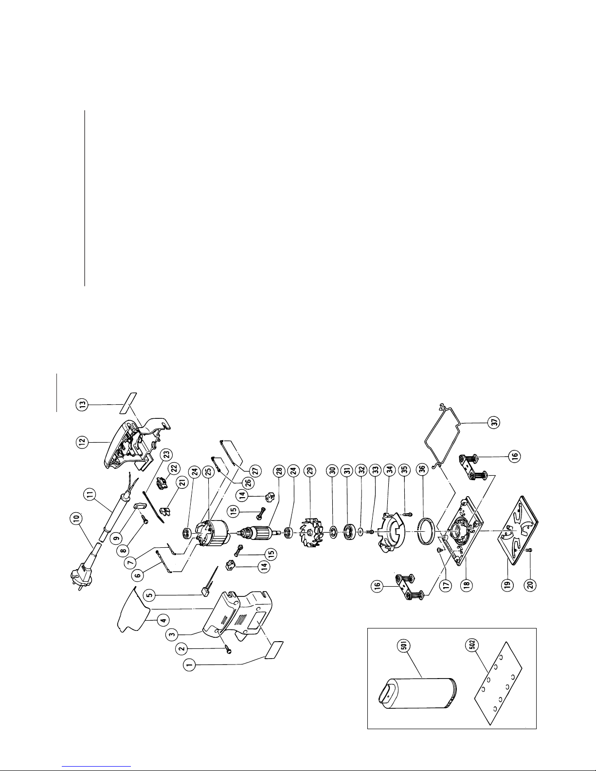
33
SV8SA
ABC D
1 ———— 1
2 301-653 4 D4×20
3 311-939 1
4 311-947 1
5 930-039 1
6 311-952 1
7 311-949 1
8 984-750 2 D4×16
9 960-266 1
10 ———— 1
11 953-327 1 D8.8
12 311-938 1
13 ———— 1
14 930-483 2
15 999-041 2
16 311-940 2
17 311-945 2 D4×10
18 311-943 1
19 1 311-152 1
19 2 311-153 1 ”FRA, BEL, SUI”
20 949-216 4 M4×10
21 938-307 1
22 311-948 1
23 310-480 1
24 608-VVM 2 608VVMC2EPS2L
25 1 340-329C 1 110V-115V
25 2 340-329E 1 220V-230V
26 311-951 1
27 311-950 1
28 1 360-369C 1 110V-115V
28 2 360-369E 1 220V-230V
29 311-941 1
30 993-052 1
31 600-1DD 1 6001DDUCMPS2S
32 875-249 1
33 997-411 1 M4×12
34 311-942 1
35 956-384 2 D4×20
36 311-946 1
37 311-944 2
501 310-339 1
502 1 311-147 1 80×170 AA100
502 2 311-150 1 80×130 AA100
Page 35
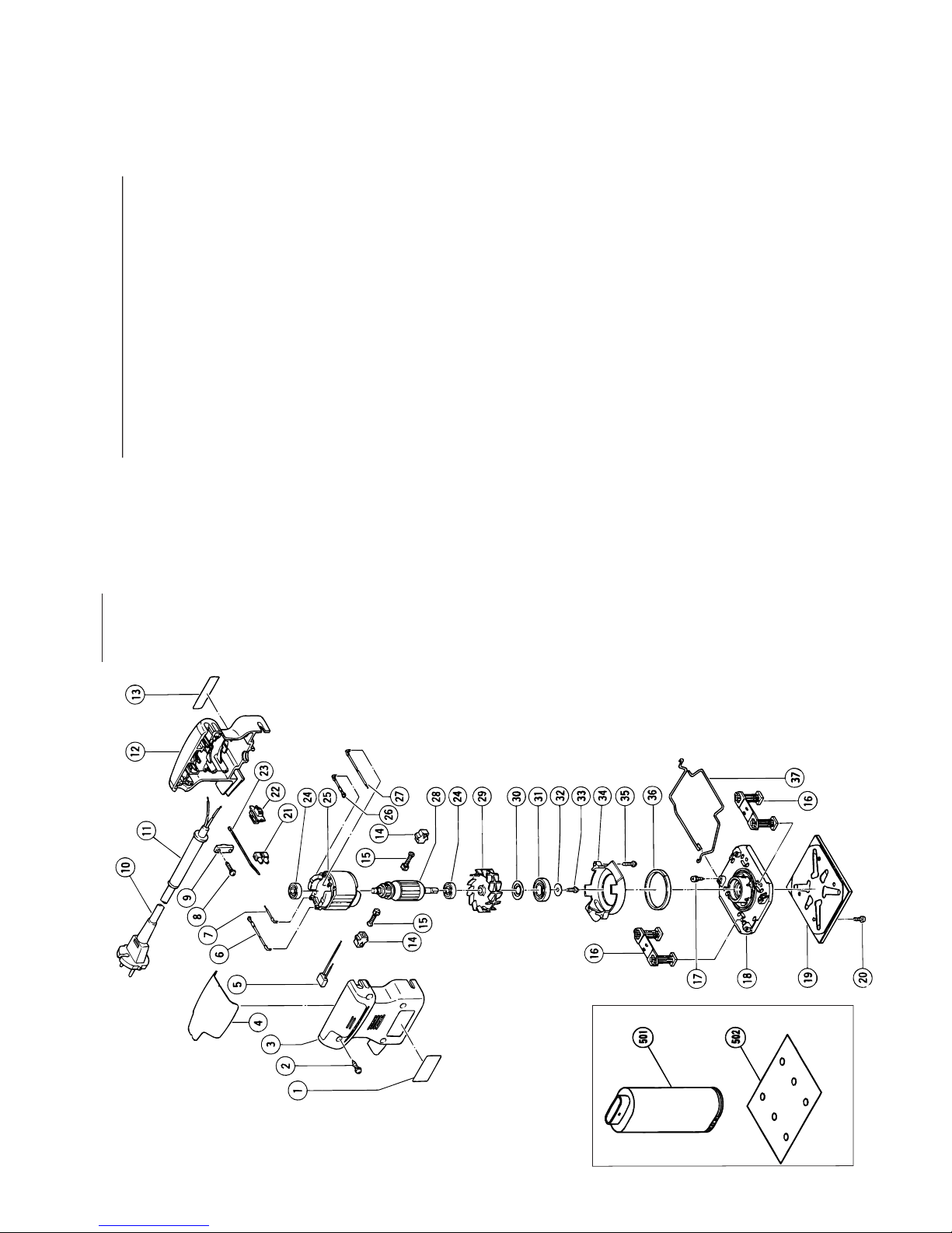
34
SV12SF
ABC D
1 ———— 1
2 301-653 4 D4×20
3 311-939 1
4 311-947 1
5 930-039 1
6 311-952 1
7 311-949 1
8 984-750 2 D4×16
9 960-266 1
10 ———— 1
11 1 953-327 1 D8.8
11 2 938-051 1 D10.1
12 311-938 1
13 ———— 1
14 930-483 2
15 999-041 2
16 311-940 2
17 311-945 2 D4×10
18 311-976 1
19 1 310-354 1
19 2 310-355 1 ”FRA, BEL, SUI”
20 949-216 4 M4×10
21 938-307 1
22 311-948 1
23 310-480 1
24 608-VVM 2 608VVMC2EPS2L
25 1 340-329C 1 110V-115V
25 2 340-329E 1 220V-230V
26 311-951 1
27 311-950 1
28 1 360-369C 1 110V-115V
28 2 360-369E 1 220V-230V
29 311-941 1
30 993-052 1
31 600-1DD 1 6001DDUCMPS2S
32 875-249 1
33 997-411 1 M4×12
34 311-942 1
35 956-384 2 D4×20
36 311-946 1
37 311-977 2
501 310-339 1
502 1 310-342 1 114×140 AA100
502 2 310-345 1 110×100 AA100
502 3 310-348 1 110×100 AA80
Page 36

35
English
Nederlands
GUARANTEE CERTIFICATE
1 Model No.
2 Serial No.
3 Date of Purchase
4 Customer Name and Address
5 Dealer Name and Address
(Please stamp dealer name and address)
Italiano Ελληνικά
Français Português
Deutsch
Español
GARANTIEBEWIJS
1 Modelnummer
2 Serienummer
3 Datum van aankoop
4 Naam en adres van de gebruiker
5 Naam en adres van de handelaar
(Stempel a.u.b. naam en adres vande de
handelaar)
GARANTIESCHEIN
1 Modell-Nr.
2 Serien-Nr.
3 Kaufdaturn
4 Name und Anschrift des Kunden
5 Name und Anschrift des Händlers
(Bitte mit Namen und Anschrift des
Handlers abstempeln)
CERTIFICADO DE GARANTIA
1 Nùmero de modelo
2 Mùmero de serie
3 Fecha de adquisición
4 Nombre y dirección del cliente
5 Nombre y dirección del distribudor
(Se ruega poner el sellú del distribudor
con su nombre y dirección)
CERTIFICAT DE GARANTIE
1 No. de modèle
2 No de série
3 Date d'achat
4 Nom et adresse du client
5 Nom et adresse du revendeur
(Cachet portant le nom et l'adresse du
revendeur)
CETTIFICADO DE GARANTIA
1 Nùmero do modelo
2 Nùmero do série
3 Data de compra
4 Nome e morada do cliente
5 Nome e morada do distribuidor
(Por favor, carímbe o nome e morada
do distribuidor)
CERTIFICATO DI GARANZIA
1 Modello
2 N° di serie
3 Data di acquisto
4 Nome e indirizzo dell'acquirente
5 Nome e indirizzo del rivenditore
(Si prega di apporre il timbro con questi
dati)
ΠΙΣΤΟΠΟΙΗΤΙΚΟ ΕΓΓΥΗΣΗΣ
1 Αρ. Μοντέλου
2 Αύξων Αρ.
3 Ηµεροµηνία αγοράς
4 ΄Ονοµα και διεύθυνση πελάτη
5 ΄Ονοµα και διεύθυνση µεταπωλητή
(Παρακαλούµε να χρησιµοποιηθεί
σφραγίδα)
✄
Page 37

36
1
2
3
4
5
✄
Page 38

37
Page 39

38
Page 40
39
Page 41

English
EC DECLARATION OF CONFORMITY
We declare under our sole responsibility that this
product is in conformity with standards or standardized
documents EN50144, EN55014 and EN61000-3 in
accordance with Council Directives 73/23/EEC, 89/336/
EEC and 98/37/EC.
This declaration is applicable to the product affixed CE
marking.
Nederlands
EC VERKLARING VAN CONFORMITEIT
Wij verklaren onder eigen verantwoordelijkheid dat dit
produkt conform de richtlijnen of gestandardiseerde
documenten EN50144, EN55014 en EN61000-3 voldoet
aan de eisen van EEG Bepalingen 73/23/EEG, 89/336/
EEG en 98/37/EC.
Deze verklaring is van toepassing op produkten
voorzien van de CE-markeringen.
Deutsch
ERKLÄRUNG ZUR KONFORMITÄT MIT CE-REGELN
Wir erklären mit alleiniger Verantwortung, daß dieses
Produkt den Standards oder standardisierten
Dokumenten EN50144, EN55014 und EN61000-3 in
Übereinstimmung mit den Direktiven des Europarats
73/23/EWG, 89/336/EWG und 98/37/CE entspricht.
Diese Erklärung gilt für Produkte, die die CE-Markierung
tragen.
Français
DECLARATION DE CONFORMITE CE
Nous déclarons sous notre seule et entière responsabilité que ce produit est conforme aux normes ou
documents normalisés EN50144, EN55014 et EN610003 en accord avec les Directives 73/23/CEE, 89/336/CEE
et 98/37/CE du Conseil.
Cette déclaration s’applique aux produits désignés CE.
Italiano
DICHIARAZIONE DI CONFORMITÀ CE
Si dichiara sotto nostra responsabilità che questo
prodotto è conforme agli standard o ai documenti
standardizzati EN50144, EN55014 e EN61000-3
conforme alle direttive 73/23/CEE, 89/336/CEE e 98/37/
CE del concilio.
Questa dichiarazione è applicabile ai prodotti cui sono
applicati i marchi CE.
Español
DECLARACIÓN DE CONFORMIDAD DE LA CE
Declaramos bajo nuestra única responsabilidad que
este producto está de acuerdo con las normas o con
los documentos de normalización EN50144, EN55014
y EN61000-3, según indican las Directrices del Consejo
73/23/CEE, 89/336/CEE y 98/37/CE.
Esta declaración se aplica a los productos con marcas
de la CE.
Portugûes
DECLARAÇÃO DE CONFORMIDADE CE
Declaramos, sob nossa única e inteira responsabilidade,
que este produto está de acordo com as normas ou
documentos normativos EN50144, EN55014 e EN610003, em conformidade com as Diretrizes 73/23/CEE, 89/
336/CEE e 98/37/CE do Conselho.
Esta declaração se aplica aos produtos designados CE.
Ελληνικά
EK ∆ΗΛ·ΣΗ ΕΝΑΡΜΟΝΙΣΜΟΥ
∆ηλώνουµε µε απ&λυτη υπευθυν&τητα &τι αυτ& το
προι&ν είναι εναρµονισµένο µε τα πρ&τυπα ή τα
έγραφα προτύπων EN50144, EN55014 και EN61000-3
σε συµφωνία µε τις Οδηγίες του Συµβουλίου 73/23/
EOK, 89/336/EOK και 98/37/EK.
Αυτή η δήλωση ισχύει στο προι&ν µε το σηµάδι CE.
Representative office in Europe
Hitachi Power Tools Europe GmbH
Siemensring 34, 47877 Willich 1, F. R. Germany
Head office in Japan
Hitachi Koki Co., Ltd.
Shinagawa Intercity Tower A, 15-1, Konan 2-chome,
Minato-ku, Tokyo, Japan
Hitachi Koki Co., Ltd.
31. 12. 2003
K. Kato
Board Director
312
Code No. C99065272
Printed in Malaysia
 Loading...