

Page 1
ZW310
-7
WHEEL LOADER TECHNICAL MANUAL
PART NO.
TONFQ50-EN-00
Technical Manual
Operational Principle
OPERATIONAL PRINCIPLE
URL:http://www.hitachi-c-m.com
ZW310
Wheel Loader
-7
PRINTED IN JAPAN (K) 2022, 02
TONFQ50-EN-00
Service Manual consists of the following separate Part No.
Technical Manual (Operational Principle) : Vol. No.TONFQ50-EN-00
Technical Manual (Troubleshooting) : Vol. No.TTNFQ50-EN-00
Workshop Manual : Vol. No.WNFQ50-EN-00
Page 2

Hitachi Construction Machinery Co., Ltd.
COPYRIGHT(C)2022
Tokyo, Japan
All rights reserved
Page 3

INTRODUCTION
To The Reader
This manual is written for an experienced technician to provide technical information needed to maintain and repair this
machine.
The machine specication and description according to destination may be explained on this manual.
● Be sure to thoroughly read this manual for correct product information and service procedures.
● If you have any questions or comments, at if you found any errors regarding the contents of this manual, please
contact using “Service Manual Revision Request Form” at the end of this manual. (Note: Do not tear o the form. Copy
this form for usage.)
• Hitachi Construction Machinery Co., Ltd.
• E-mail: HCM-TIC-GES@hitachi-kenki.com
All information, illustrations and specications in this manual are based on the latest product information available at the
time of publication. The right is reserved to make changes at any time without notice.
Additional References
Please refer to the other materials (operator’s manual, parts catalog, engine technical material and Hitachi training
material etc.) in addition to this manual.
Manual Composition
This manual consists the Technical Manual, the Workshop Manual and the Engine Manual.
● Information included in the Technical Manual: Technical information needed for redelivery and delivery
• Operation and activation of all devices and systems, operational performance tests, and troubleshooting
procedures.
● Information included in the Workshop Manual: Technical information needed for maintenance and repair of the
machine
• Tools and devices needed for maintenance and repair, maintenance standards, and removal / installation and
assemble / disassemble procedures
● Information included in the Engine Manual: Technical information needed for redelivery and delivery and
maintenance and repair of the machine
• Operation and activation of all devices and systems, troubleshooting and assemble / disassemble procedures
Page Number
Each page has a number, located on the center lower part of the page. Each number contains the following information:
● Technical Manual: T 1-3-5
T Technical Manual
1 Section Number
3 Group Number
5 Consecutive Page Number for Each Group
● Workshop Manual: W 1-3-2-5
W Workshop Manual
1 Section Number
3 Group Number
2 Sub Group Number
5 Consecutive Page Number for Each Group
TONFQ50-EN-00(28/02/2022)
IN-1
Page 4

INTRODUCTION
Trademark
AdBlue® is a registered trademark of the Verband der Automobilindustrie e.V. (VDA).
Safety Alert Symbol and Headline Notations
In this manual, the following safety alert symbol and signal words are used to alert the reader to the potential for personal
injury of machine damage.
WARNING
This is the safety alert symbol. When you see this symbol, be alert to the potential for personal injury. Never fail to
follow the safety instructions prescribed along with the safety alert symbol. The safety alert symbol is also used to
draw attention to component/part weights. To avoid injury and damage, be sure to use appropriate lifting
techniques and equipment when lifting heavy parts.
CAUTION
Indicates potentially hazardous situation which could, if not avoided, result in personal injury or death. This is also
provided before the indication of mass to draw attention to safety during handling of the machine.
IMPORTANT
Indicates a situation which, if not conformed to the instructions, could result in damage to the machine. This header is
given to matters that are important in terms of operation and management.
NOTE
Indicates supplementary technical information or know-how.
Units Used
SI Units (International System of Units) are used in this manual.
A table for conversion from SI units to other system units is shown below for reference purposes.
Quantity To Convert From Into Multiply By
Length mm in 0.03937
mm ft 0.003281
Volume L US gal 0.2642
L US qt 1.057
3
m
Weight kg lb 2.205
Force N kgf 0.10197
N lbf 0.2248
Torque N·m kgf·m 0.10197
Pressure MPa
MPa psi 145.0
Power kW PS 1.360
kW HP 1.341
Temperature °C °F °C×1.8+32
3
yd
kgf/cm
1.308
2
10.197
TONFQ50-EN-00(28/02/2022)
IN-2
Page 5

INTRODUCTION
Quantity To Convert From Into Multiply By
Velocity km/h mph 0.6214
-1
min
Flow rate L/min US gpm 0.2642
mL/rev cc/rev 1.0
rpm 1.0
TONFQ50-EN-00(28/02/2022)
IN-3
Page 6

MEMO
INTRODUCTION
TONFQ50-EN-00(28/02/2022)
IN-4
Page 7

Symbol and Abbreviation
SYMBOL AND ABBREVIATION
Symbol and Abbrevia
tion
TO Technical manual (Operational
principle)
TT Technical manual (Trouble
shooting)
T/M Technical manual Technical manual.
W, W/M Workshop manual Workshop manual (Removal and Installation, Disassembly and
MC Main Controller Main controller. MC controls the engine, pump, and valve ac
ECM Engine Control Module Engine controller. ECM controls fuel injection amount accord
VGS Variable Geometry System con
troller
GSM Global System for Mobile com
munications controller
GPS Global Positioning System Global positioning system.
CAN Controller Area Network CAN communication. CAN is a serial communications protocol
A/C Air Conditioner Air conditioner.
OP, OPT Option Optional component.
MPDr. Maintenance Pro Dr. MPDr. is software that troubleshooting, monitoring, and ad
A/I Auto-Idle Auto-idle.
WU Warming-Up Warming-up.
Li Low (Slow) Idle Minimum Rotation Engine Speed.
ATT Attachment Attachment. Attachment is optional parts such as breaker,
HI, Hi High Travel fast position.
LO, Lo Low Travel slow position.
DPF Diesel Particulate Filter DPF is a lter which removes particulate matter (PM) including
DPD Diesel Particulate Diuser DPD is an exhaust emission control system, a type of DPF,
Part Name Explanation
Technical manual (Operational Principle).
Technical manual (Troubleshooting).
Assembly).
cording to the machine operating condition.
ing to the machine operating condition.
Variable turbo controller. VGS is an exhaust turbo charged sys
tem to supercharge the exhaust energy while running the en
gine at slow idle speed. VGS optimizes the turbine rotation, im
proves the performance at slow-speed torque and the acceler
ation, reduces fuel consumption, and reduces particulate mat
ter (PM) by adjusting the nozzle opening of turbine housing.
Communication controller. GSM is a type of wireless communi
cation system, is used in more than on 100 countries around
Europe and Asia, and becomes the factual global standards of
the mobile telephone.
internationally-standardized by ISO (International Organiza
tion for Standardization).
justment.
crusher, and pulverizer in this manual.
the toxic substance of exhaust gas of the diesel engine. Ex
haust particulate removal equipment.
which cleans up particulate matter (PM) of diesel engine ex
haust gas. DPD is a ceramic lter which traps and lters PM of
exhaust gas. DPD burns up accumulated PM when PM increa
ses and regenerates the lter.
TONFQ50-EN-00(28/02/2022)
SY-1
Page 8

SYMBOL AND ABBREVIATION
Symbol and Abbrevia
tion
DOC Diesel Oxidation Catalyst Oxidation catalyst for the diesel engine. Diesel oxidation cata
CSF Catalyzed Soot Filter Filter. The lter traps, burns, and remove particulate matter
PM Particulate Matter Particulate matter.
EGR Exhaust Gas Recirculation The EGR control re-circulates a part of exhaust gas in the in
ML Moment Limiter ML crane.
HRV Hose Rupture Valve Hose rupture valve.
LLC Long Life Coolant Long life coolant.
SCR Selective Catalytic Reduction The urea SCR system injects diesel exhaust uid to nitrogen
DCU Dosing Control Unit Urea SCR system controller. DCU controls the DEF injection
S/M Supply Module DEF supply module. The DEF supply module pumps diesel ex
D/M Dosing Module Dosing module. The dosing module (D/M) injects DEF into the
NOx Nitrogen Oxide Nitrogen oxide.
DEF Diesel Exhaust Fluid DEF. The DEF concentration is 32.5%, which is specied in
TPD Torque Proportioning Dieren
tial
LSD Limited Slip Dierential Limited Slip Dierential. The Limited Slip Dierential prevents
TBAP Temperature Barometric At
mospheric Pressure
JSS Joystick Steering System Joystick steering system. Operating the joystick steering lever
Part Name Explanation
lyst oxidizes unburnt fuel and raises exhaust temperature.
(PM) by using high-temperature-exhaust gas with diesel oxida
tion catalyst. Catalyst is applied onto the lter. This advances
PM burning.
take manifold and combines it with intake-air. Therefore, com
bustion temperature is lowered, and generation of nitrogen
oxides (NOx) is controlled.
oxide (NOx) exhausted from the engine and puries NOx.
amount according to the machine operating condition.
haust uid to the dosing module (D/M). Then, it returns diesel
exhaust uid in the DEF circuit when the key switch is turned
OFF.
exhaust piping according to the signal from DCU.
ISO22241.
Torque proportioning dierential. The torque proportioning
dierential prevents the tires from slipping.
the tires from slipping.
Atmospheric pressure, intake-air temperature, and intake-air
pressure.
controls the steering operation of the vehicle.
TONFQ50-EN-00(28/02/2022)
SY-2
Page 9

CONTRASTING LIST OF PART NAME
Contrasting List of Part Name between Technical Manual and Parts Catalog
Part name in technical manual Part name in parts catalog Part No.
Bucket Angle Sensor SENSOR;ANGLE YA00051742
Lift Arm Angle Sensor SENSOR;ANGLE YA00051742
TBAP Sensor SENSOR YL00009955
Hydraulic Oil Level Sensor SWITCH;LEVEL 4259787
Hydraulic Oil Temperature Sensor SENSOR 4697482
Fuel Level Sensor FLOAT 3582860580
Water Separator Sensor FILTER;FUEL YA00060028
Transmission Intermediate Shaft Speed Sensor SENSOR;REVOLUTION YB00004091
Torque Converter Output Shaft Speed Sensor SENSOR;REVOLUTION YB00004091
Torque Converter Input Shaft Speed Sensor SENSOR;REVOLUTION YB00004091
Vehicle Speed Sensor SENSOR;REVOLUTION YB00004091
Transmission Oil Temperature Sensor SENSOR;THERMO 3582960140
Service Brake Secondary Pressure Sensor SENSOR;PRESSURE YA00057050
Axle oil Temperature Sensor SENSOR;THERMO 3113925
Accelerator Pedal Sensor PEDAL;ACCELERATOR YA00003929
Brake Pedal Position Sensor SENSOR;ANGLE YA00050561
Fan Circuit Pressure Sensor SENSOR;PRESSURE 4436271
Pump Delivery Pressure Sensor SENSOR;PRESSURE 4436271
Primary Pilot Pressure Sensor SENSOR;PRESSURE YA00057050
Parking Brake Pressure Sensor SENSOR;PRES. 4436536
Service Brake Primary Pressure Sensor SENSOR;PRESSURE 4436271
Emergency Steering Pump Delivery Pressure Sen
sor
Position Sensor SENSOR;INERTIA YK00000145
Frost Sensor SENSOR;THERMO XB00001052
Re-circulated Air Temperature Sensor SENSOR;THERMO XB00001061
Solar Radiation Sensor SENSOR 4405814
Refrigerant Pressure Sensor HOSE;COOLER 4312426110
Ambient Temperature Sensor SENSOR 4405815
Lift Arm Bottom Pressure Sensor SENSOR;PRESSURE 4436271
Lift Arm Rod Pressure Sensor SENSOR;PRESSURE 4436271
Object Detection Sensor SENSOR YA00055127
DEF Quality Sensor TANK;UREA YA00070108
DEF Tank Level Sensor TANK;UREA YA00070108
DEF Tank Temperature Sensor TANK;UREA YA00070108
Steering LS Pressure Sensor SENSOR;PRESSURE YA00057050
SENSOR;PRESSURE 4436271
TONFQ50-EN-00(28/02/2022)
CO-1
Page 10

MEMO
CONTRASTING LIST OF PART NAME
TONFQ50-EN-00(28/02/2022)
CO-2
Page 11

SECTION AND GROUP
CONTENTS
TECHNICAL MANUAL
( O p e r a t i o n a l
P r i n c i p l e )
SECTION 1 GENERAL
Group 1 Specications
Group 2 Component Layout
Group 3 Component Specications
SECTION 2 SYSTEM
Group 1 Controller
Group 2 Control System
Group 3 Engine System
Group 4 Hydraulic System
Group 5 Electrical System
SECTION 3 COMPONENT OPERATION
Group 1 Pump Device
Group 2 Control Valve
Group 3 Cooling Fan System
Group 4 Steering Pilot Valve
Group 5 Steering Valve
Group 6 Charging Circuit
Group 7 Drive Unit
Group 8 Axle
Group 9 Brake Valve
Group 10 DEF Supply System
Group 11 Others
Page 12

MEMO
TONFQ50-EN-00(28/02/2022)
Page 13

SECTION 1
GENERAL
CONTENTS
Specications............................................T1-1-1
Specications ........................................................................ T1-1-1
Component Layout...................................T1-2-1
Main Component (Overview)..........................................T1-2-1
Main Component................................................................. T1-2-2
Electrical System (Overview) ...........................................T1-2-3
Air Cleaner and Radiator Assembly............................... T1-2-3
Radiator Assembly............................................................... T1-2-4
Battery Box............................................................................. T1-2-4
Hydraulic Oil Tank................................................................ T1-2-5
Fuel Tank .................................................................................T1-2-6
Drive Unit................................................................................ T1-2-7
Front Axle................................................................................T1-2-7
Cab ............................................................................................ T1-2-8
Front Console........................................................................T1-2-9
Panel Switch.........................................................................T1-2-10
Right Console......................................................................T1-2-11
Operator's Seat and Joystick Steering System........T1-2-12
Rear Console........................................................................T1-2-13
Control Unit .........................................................................T1-2-14
Column Monitor.................................................................T1-2-15
Engine....................................................................................T1-2-16
Aftertreatment Device.....................................................T1-2-17
Fan Valve...............................................................................T1-2-17
Pump Device .......................................................................T1-2-18
Control Valve .......................................................................T1-2-19
Brake Valve...........................................................................T1-2-20
Brake Charge Valve/Combination Valve....................T1-2-20
Steering Valve .....................................................................T1-2-21
Ride Control Valve.............................................................T1-2-22
2-Spool Solenoid Valve Unit ..........................................T1-2-22
Emergency Steering Pump Unit...................................T1-2-23
DEF Tank................................................................................T1-2-23
DEF Supply Module...........................................................T1-2-24
Joystick Steering Hydraulic Component...................T1-2-24
Joystick Steering Valve.....................................................T1-2-25
Joystick Steering Solenoid Valve Unit........................T1-2-25
Steering Pilot Valve...........................................................T1-2-26
Component Specications.......................T1-3-1
Specications of Engine.................................................... T1-3-1
Specications of Engine Accessories............................T1-3-5
Specications of Hydraulic Component...................... T1-3-6
Electrical Component......................................................... T1-3-8
TONFQ50-EN-00(28/02/2022)
Page 14

MEMO
TONFQ50-EN-00(28/02/2022)
Page 15

SECTION 2
SYSTEM
CONTENTS
Controller ..................................................T2-1-1
Outline of Controller........................................................... T2-1-1
CAN Circuit............................................................................. T2-1-1
Control System..........................................T2-2-1
Outline of Control System ................................................T2-2-1
Engine Control (ECM)......................................................... T2-2-1
Engine Control System Layout........................................T2-2-2
Engine Protection Control................................................T2-2-3
Accelerator Pedal Control................................................. T2-2-5
Auto Warming-Up Control ...............................................T2-2-7
Engine Torque Idle Speed-Up Control .........................T2-2-9
Forward/Reverse Selection Speed Limit Control
While Traveling..............................................................T2-2-11
Engine Speed Limit Control without Load...............T2-2-14
Matching Control While Digging.................................T2-2-16
Speed Limit Control with Power Mode OFF.............T2-2-19
Auto Power Up Speed Control......................................T2-2-21
Overheat Prevention Speed Limit Control ...............T2-2-24
Aftertreatment Device Manual Regeneration
Control..............................................................................T2-2-26
Engine Over Speed Limit Control ................................T2-2-28
Engine Max. Speed Limit Control at Stroke End
Stall and Front Relief ...................................................T2-2-30
Engine Torque Limit Control During Acceleration..
.............................................................................................T2-2-32
Pump Control......................................................................T2-2-34
Pump Control System Layout........................................T2-2-35
Base Torque Control..........................................................T2-2-36
Torque Decrease Control While Digging...................T2-2-37
Transmission Control (TCU)............................................T2-2-39
Transmission Control System Layout..........................T2-2-40
Neutral Control...................................................................T2-2-41
Forward/Reverse Lever Priority Control.....................T2-2-43
Manual Speed Shift Control...........................................T2-2-45
Automatic Speed Shift Control.....................................T2-2-47
Downshift Control.............................................................T2-2-50
Rise Run Shift Prohibit Control......................................T2-2-52
Clutch Cuto Control........................................................T2-2-54
Shift Holding Control........................................................T2-2-56
Lock Up Control..................................................................T2-2-58
Fan Control, Valve Control ..............................................T2-2-60
Fan Control, Valve Control System Layout................T2-2-61
Fan Speed Control .............................................................T2-2-62
Fan Reverse Rotation Control........................................T2-2-63
Fan Speed Control During Transmission Learning.
.............................................................................................T2-2-66
Front Attachment Operation Circuit Selection
Control..............................................................................T2-2-67
Ride Control.........................................................................T2-2-69
Control by Electrical and Hydraulic Combined
Circuit................................................................................T2-2-71
Bucket Auto Leveler Control..........................................T2-2-72
Lift Arm Float Control.......................................................T2-2-73
Front Loader Device Control..........................................T2-2-75
Outline of Front Attachment Operation Control.....
.............................................................................................T2-2-75
Process of Front Attachment Operation Control.....
.............................................................................................T2-2-76
Front Attachment Failure Detection ...........................T2-2-78
Detent Control....................................................................T2-2-80
3rd/4th Lever Control.......................................................T2-2-82
Control Lever Lock Control.............................................T2-2-83
Other Controls ....................................................................T2-2-85
Transmission Alarm Control...........................................T2-2-85
Parking Brake Operation Indicator Control..............T2-2-86
Brake Oil Low Pressure Indicator Control..................T2-2-87
Low Steering Oil Pressure Indicator Control............T2-2-88
Overrun Alarm Control ....................................................T2-2-89
Lift Arm Auto Leveler Height Kickout Control.........T2-2-91
Lift Arm Auto Leveler Lower Kickout Control..........T2-2-92
Quick Power Mode Control............................................T2-2-94
Auto Shut-Down Control................................................T2-2-95
Emergency Steering Control .........................................T2-2-98
Coolant Level Switch Control .....................................T2-2-100
Payload Checker Control.............................................. T2-2-100
Object Detection Sensor Control.............................. T2-2-101
Process of Object Detection Sensor Control......... T2-2-102
Notication Processing (Leveling)............................ T2-2-103
Scooping Flag ..................................................................T2-2-104
User Interface ................................................................... T2-2-104
Aerial Angle Control.......................................................T2-2-106
JSS Control System......................................................... T2-2-109
Joystick Steering Lever Control ................................. T2-2-109
Forward/Reverse Switch Control (JSS).................... T2-2-111
Alarm Control (JSS)......................................................... T2-2-114
Engine System ..........................................T2-3-1
Outline of ECM System ......................................................T2-3-1
Fuel Injection Control......................................................... T2-3-1
Fuel Injection Amount Control....................................... T2-3-2
TONFQ50-EN-00(28/02/2022)
Page 16

Fuel Injection Timing Control.......................................... T2-3-3
Fuel Injection Rate Control............................................... T2-3-5
Fuel Injection Pressure Control....................................... T2-3-7
Fuel Injection Amount Correction Control................. T2-3-8
Preheating Control.............................................................. T2-3-9
Alarm Control......................................................................T2-3-10
Urea SCR System................................................................T2-3-11
DEF Injection Control .......................................................T2-3-11
Start-Up Control.................................................................T2-3-12
DEF Defrosting Control....................................................T2-3-13
DEF Thermal Control ........................................................T2-3-14
After-Run Control...............................................................T2-3-15
Engine Output Restriction Control (INDUCEMENT)
.............................................................................................T2-3-16
Insucient DEF Level.......................................................T2-3-17
Malfunction of Urea SCR System..................................T2-3-18
Outline of Aftertreatment Device................................T2-3-19
Operation of Aftertreatment Device...........................T2-3-20
Aftertreatment Device Regeneration Control.........T2-3-21
Hydraulic System......................................T2-4-1
Outline of Hydraulic System ............................................ T2-4-1
Pilot Circuit of Hydraulic System.................................... T2-4-1
Charging Circuit ...................................................................T2-4-3
Charging Circuit (Outline)................................................. T2-4-3
Charging Circuit (When service brake is not
stepped)............................................................................. T2-4-4
Charging Circuit (When service brake is stepped)..
............................................................................................... T2-4-6
Service Brake Circuit ...........................................................T2-4-7
Service Brake Circuit (When brake is applied)........... T2-4-7
Service Brake Circuit (When brake is released) .........T2-4-8
Parking Brake Circuit...........................................................T2-4-8
Parking Brake Circuit (Outline)........................................ T2-4-9
Parking Brake Circuit (When parking brake is
applied).............................................................................. T2-4-9
Parking Brake Circuit (When parking brake is
released) ..........................................................................T2-4-10
Lift Arm/Bucket Operation Control Circuit...............T2-4-11
Lift Arm/Bucket Operation Control Circuit
(Outline)...........................................................................T2-4-11
Fan Circuit.............................................................................T2-4-12
Fan Reverse Rotation Control Circuit..........................T2-4-13
Fan Speed Control Circuit...............................................T2-4-14
Fan Circuit (Prevention of Cavitation).........................T2-4-15
Ride Control Circuit...........................................................T2-4-16
Main Circuit of Hydraulic System.................................T2-4-17
Main Circuit of Hydraulic System (Outline) ..............T2-4-18
Steering Priority Circuit....................................................T2-4-19
Steering Priority Circuit (When not Operated)........T2-4-19
Steering Priority Circuit (When Operated)................T2-4-20
Steering Operation Control Circuit..............................T2-4-22
Steering Operation Control Circuit (Outline)...........T2-4-22
Steering Operation Control Circuit (Steering
Operation).......................................................................T2-4-23
Steering Operation Control Circuit (Steering Stop
Operation).......................................................................T2-4-25
Front Attachment Control Circuit ................................T2-4-26
Neutral Circuit.....................................................................T2-4-27
Flow Rate Control Circuit................................................T2-4-28
Relief Circuit.........................................................................T2-4-29
Single Operation Circuit..................................................T2-4-30
Combined Operation Circuit (Combined
Operation of Lift Arm Raise and Bucket Dump).
.............................................................................................T2-4-31
Combined Operation Circuit (Combined
Operation of Steering and Lift Arm Raise) ..........T2-4-33
Pump Control Circuit........................................................T2-4-35
Parallel Circuit Flow Rate Control.................................T2-4-37
Emergency Steering Circuit ...........................................T2-4-38
Outline of JSS Hydraulic System...................................T2-4-40
Pilot Circuit of JSS Hydraulic System...........................T2-4-41
Joystick Steering Operation Control Circuit.............T2-4-41
Joystick Steering Operation (When Operating
Steering Wheel).............................................................T2-4-43
Electrical System.......................................T2-5-1
Outline of Electrical System .............................................T2-5-1
Main Circuit of Electrical System.................................... T2-5-1
Electric Power Circuit (Key Switch: OFF)......................T2-5-1
CAN Circuit............................................................................. T2-5-3
Accessory Related Circuits (Key Switch: ACC)............ T2-5-6
Starting Circuit (Key Switch: START)..............................T2-5-7
Charging Circuit (Key Switch: ON) ................................. T2-5-8
Surge Voltage Prevention Circuit................................... T2-5-9
Control Lever Lock Circuit (Key Switch: ON).............T2-5-10
Auto Shut-down Circuit...................................................T2-5-12
Engine Stop Circuit............................................................T2-5-14
Air Conditioner Circuit .....................................................T2-5-15
Column Box Circuit............................................................T2-5-16
Headlight Circuit (Clearance Light, License Light,
Tail Light Circuit (Light Switch: Clearance Light
Position))..........................................................................T2-5-16
Headlight Circuit (Dimmer Switch: Low Beam
Position)...........................................................................T2-5-18
High Beam Circuit..............................................................T2-5-20
Hazard Light Circuit (Key Switch: OFF).......................T2-5-21
Turn Signal Light Circuit..................................................T2-5-23
Horn Circuit (Key Switch: OFF) ......................................T2-5-24
Back Buzzer Circuit............................................................T2-5-24
Brake Light Circuit .............................................................T2-5-25
Parking Brake Circuit (Parking Brake: Released
(Parking Switch: Release Position))........................T2-5-26
Parking Brake Circuit (Parking Brake: Applied
(Parking Switch: Apply Position).............................T2-5-27
Accessory Circuit of Electrical System........................T2-5-28
Work Light Circuit..............................................................T2-5-28
Front Wiper Circuit ............................................................T2-5-29
Rear Wiper Circuit..............................................................T2-5-31
Washer Circuit.....................................................................T2-5-32
Cab Light Circuit.................................................................T2-5-33
TONFQ50-EN-00(28/02/2022)
Page 17

SECTION 3
COMPONENT OPERATION
CONTENTS
Pump Device .............................................T3-1-1
Outline of Pump Device ....................................................T3-1-1
Outline of Main Pump........................................................ T3-1-1
Increasing and Decreasing of Main Pump Delivery
Flow Rate...........................................................................T3-1-2
Outline of Regulator ...........................................................T3-1-5
Regulator Control Function..............................................T3-1-6
Control by Pump Control Pressure................................ T3-1-6
Maximum Torque Control................................................. T3-1-9
Control by Pilot Pressure from Torque Control
Solenoid Valve...............................................................T3-1-11
Outline of Pilot Pump.......................................................T3-1-13
Outline of Pump Delivery Pressure Sensor...............T3-1-13
Control Valve.............................................T3-2-1
Outline of Control Valve.................................................... T3-2-1
Components in Control Valve .........................................T3-2-2
Main Circuit of Control Valve.........................................T3-2-10
Pilot Operation Control Circuit of Control Valve.....T3-2-12
External Pilot Pressure Circuit of Control Valve.......T3-2-13
Outline of Main Relief Valve...........................................T3-2-16
Relief Operation of Main Relief Valve .........................T3-2-16
Outline of Overload Relief Valve (With Make-Up
Function) .........................................................................T3-2-17
Relief Operation of Overload Relief Valve.................T3-2-17
Make-Up Operation of Overload Relief Valve..........T3-2-18
Outline of Bleed-O Compensator .............................T3-2-19
Operation of Bleed-O Compensator........................T3-2-19
Operation of Bucket Spool (Bucket Tilt) ....................T3-2-22
Operation of Bucket Spool (Bucket Dump)..............T3-2-24
Operation of Lift Arm Spool (Lift Arm Raise) ...........T3-2-26
Operation of Lift Arm Spool (Lift Arm Lower)..........T3-2-28
Operation of Lift Arm Spool (Lift Arm Float)............T3-2-30
Outline of Pump Flow Rate Control Valve.................T3-2-32
Operation (When the Control Lever is in Neutral)
of Pump Flow Rate Control Valve ...........................T3-2-32
Operation (When the Control Lever is Operated)
of Pump Flow Rate Control Valve ...........................T3-2-34
Outline of Solenoid Valve (Built-in Control Valve) ..
.............................................................................................T3-2-36
Outline of Lift Arm Flow Rate Control Valve.............T3-2-36
Operation (When In Neutral) of Lift Arm Flow Rate
Control Valve..................................................................T3-2-36
Operation (When the Flow Rate Control) of Lift
Arm Flow Rate Control Valve....................................T3-2-38
Outline of Ride Control Selector Solenoid Valve....T3-2-40
Operation of Ride Control Selector Solenoid Valve
.............................................................................................T3-2-40
Cooling Fan System ..................................T3-3-1
Outline of Fan Motor .......................................................... T3-3-1
Outline of Fan Valve............................................................ T3-3-1
Operation of Fan Valve (Normal Rotation).................. T3-3-2
Operation of Fan Valve (Reverse Rotation)................. T3-3-4
Operation of Fan Valve (With Fan Speed
Controlled)........................................................................ T3-3-6
Make-Up Operation of Fan Valve...................................T3-3-8
Steering Pilot Valve ..................................T3-4-1
Outline of Steering Pilot Valve........................................ T3-4-1
Structure of Steering Pilot Valve.....................................T3-4-1
Operation of Steering Pilot Valve...................................T3-4-3
Operation of Steering Pilot Valve (Left Steering) ....
............................................................................................... T3-4-4
Operation of Steering Pilot Valve (Right Steering) .
............................................................................................... T3-4-6
Operation of Steering Pilot Valve (Neutral) ................ T3-4-6
Steering Valve ...........................................T3-5-1
Outline of Steering Valve.................................................. T3-5-1
Structure of Steering Valve...............................................T3-5-1
Operation of Steering Valve............................................. T3-5-4
Outline of Meter-in Compensator .................................T3-5-7
Operation of Meter-in Compensator............................ T3-5-7
Outline of Steering Main Relief Valve........................... T3-5-8
Relief Operation of Steering Main Relief Valve .........T3-5-9
Outline of Steering Overload Relief Valve.................T3-5-10
Relief Operation of Steering Overload Relief Valve
.............................................................................................T3-5-11
Make-Up Operation of Steering Overload Relief
Valve..................................................................................T3-5-12
Charging Circuit........................................T3-6-1
Outline of Charging Circuit ..............................................T3-6-1
Operation of Brake Charge Valve (Between
Pressure Charging Start and Pressure Charging
Finish) .................................................................................T3-6-1
Operation of Brake Charge Valve (After Pressure
Charging Finish).............................................................. T3-6-3
Structure of Combination Valve..................................... T3-6-6
Operation of Reducing Valve...........................................T3-6-7
TONFQ50-EN-00(28/02/2022)
Page 18

Specications of Primary Pilot Pressure Sensor........ T3-6-8
Outline of Lift Arm Flow Rate Control Solenoid
Valve..................................................................................T3-6-10
Outline of Proportional Solenoid Valve.....................T3-6-11
Operation of Proportional Solenoid Valve (When
in Neutral) .......................................................................T3-6-11
Operation of Proportional Solenoid Valve (When
Excited).............................................................................T3-6-12
Outline of Service Brake Accumulator .......................T3-6-13
Drive Unit ..................................................T3-7-1
Outline of Drive Unit........................................................... T3-7-1
Structure of Drive Unit....................................................... T3-7-2
Operation of Torque Converter ......................................T3-7-6
Outline of Transmission..................................................... T3-7-8
Operation of Transmission (Forward First Speed)...
.............................................................................................T3-7-10
Operation of Transmission (Forward Second
Speed) ..............................................................................T3-7-13
Operation of Transmission (Forward Third Speed).
.............................................................................................T3-7-16
Operation of Transmission (Forward Fourth
Speed) ..............................................................................T3-7-19
Operation of Transmission (Reverse First Speed)....
.............................................................................................T3-7-22
Operation of Transmission Control Valve..................T3-7-25
Outline of Transmission Regulator Valve ..................T3-7-29
Operation of Transmission Regulator Valve .............T3-7-31
Outline of Transmission Oil Filter Relief Valve.........T3-7-35
Operation of Transmission Oil Filter Relief Valve.....
.............................................................................................T3-7-36
Outline of Torque Converter Check Valve.................T3-7-37
Operation of Torque Converter Check Valve ...........T3-7-37
Outline of Parking Brake .................................................T3-7-39
Operation of Parking Brake............................................T3-7-40
Parking Brake Manual Release ......................................T3-7-42
Drive Unit Circuit................................................................T3-7-43
Axle............................................................T3-8-1
Outline of Axle ...................................................................... T3-8-1
Structure of Dierential Gear ..........................................T3-8-1
Purpose of Dierential Gear.............................................T3-8-2
Basic Operational Principle of Dierential Gear .......T3-8-3
Operation of Dierential Gear......................................... T3-8-3
Outline of Torque Proportioning Dierential (TPD)
............................................................................................... T3-8-4
Operation of Torque Proportioning Dierential
(TPD) ................................................................................... T3-8-5
Outline of Limited Slip Dierential (LSD).................... T3-8-6
Operation of Limited Slip Dierential (LSD)............... T3-8-7
Outline of Service Brake ....................................................T3-8-7
Operation of Service Brake (When Brake Is
Applied) .............................................................................T3-8-7
Operation of Service Brake (When Brake Is
Released) ...........................................................................T3-8-8
Outline of Final Drive/Axle Shaft.................................... T3-8-9
Brake Valve
Outline of Brake Valve........................................................ T3-9-1
Operation of Brake Valve (When Brake Pedal Is In
Neutral) (Output Curve: A to B) ................................. T3-9-1
Operation of Brake Valve (During Metering or
Decompressing) (Output Curve: B-C) .....................T3-9-3
Operation of Brake Valve (Full Stroke) (Output
Curve: C to D)................................................................... T3-9-5
................................................T3-9-1
DEF Supply System.................................T3-10-1
Outline of DEF Supply System ......................................T3-10-1
Outline of DEF Tank...........................................................T3-10-1
Outline of DEF Hose..........................................................T3-10-2
Outline of DEF Sensor Unit.............................................T3-10-2
Outline of DEF Sensor Head Unit .................................T3-10-2
Functions of DEF Sensor Unit Parts.............................T3-10-3
Outline of DEF Supply Module .....................................T3-10-4
Outline of Coolant Line....................................................T3-10-5
Others......................................................T3-11-1
Outline of Propeller Shaft ...............................................T3-11-1
Outline of 2-Spool Solenoid Valve Unit.....................T3-11-2
Outline of Steering Accumulator.................................T3-11-2
Outline of Ride Control Valve........................................T3-11-3
Operation of Ride Control Valve (Control for Ride
Control: When Not Operating) ................................T3-11-4
Operation of Ride Control Valve (Control for Ride
Control: When Operating).........................................T3-11-5
Outline of Ride Control Accumulator.........................T3-11-6
Outline of Check Valve.....................................................T3-11-7
Operation of Stop Valve..................................................T3-11-7
Outline of Pilot Filter.........................................................T3-11-8
Outline of Emergency Steering Pump Unit..............T3-11-9
Outline of Joystick Steering Valve................................T3-11-9
Operation of Joystick Steering Valve (Right Turn) ..
.......................................................................................... T3-11-11
Operation of Joystick Steering Valve (Left Turn) .T3-11-11
TONFQ50-EN-00(28/02/2022)
Page 19

SECTION 1
GENERAL
CONTENTS
Specications............................................T1-1-1
Specications ........................................................................ T1-1-1
Component Layout...................................T1-2-1
Main Component (Overview)..........................................T1-2-1
Main Component................................................................. T1-2-2
Electrical System (Overview) ...........................................T1-2-3
Air Cleaner and Radiator Assembly............................... T1-2-3
Radiator Assembly............................................................... T1-2-4
Battery Box............................................................................. T1-2-4
Hydraulic Oil Tank................................................................ T1-2-5
Fuel Tank .................................................................................T1-2-6
Drive Unit................................................................................ T1-2-7
Front Axle................................................................................T1-2-7
Cab ............................................................................................ T1-2-8
Front Console........................................................................T1-2-9
Panel Switch.........................................................................T1-2-10
Right Console......................................................................T1-2-11
Operator's Seat and Joystick Steering System........T1-2-12
Rear Console........................................................................T1-2-13
Control Unit .........................................................................T1-2-14
Column Monitor.................................................................T1-2-15
Engine....................................................................................T1-2-16
Aftertreatment Device.....................................................T1-2-17
Fan Valve...............................................................................T1-2-17
Pump Device .......................................................................T1-2-18
Control Valve .......................................................................T1-2-19
Brake Valve...........................................................................T1-2-20
Brake Charge Valve/Combination Valve....................T1-2-20
Steering Valve .....................................................................T1-2-21
Ride Control Valve.............................................................T1-2-22
2-Spool Solenoid Valve Unit ..........................................T1-2-22
Emergency Steering Pump Unit...................................T1-2-23
DEF Tank................................................................................T1-2-23
DEF Supply Module...........................................................T1-2-24
Joystick Steering Hydraulic Component...................T1-2-24
Joystick Steering Valve.....................................................T1-2-25
Joystick Steering Solenoid Valve Unit........................T1-2-25
Steering Pilot Valve...........................................................T1-2-26
Component Specications.......................T1-3-1
Specications of Engine.................................................... T1-3-1
Specications of Engine Accessories............................T1-3-5
Specications of Hydraulic Component...................... T1-3-6
Electrical Component......................................................... T1-3-8
TONFQ50-EN-00(28/02/2022)
Page 20

MEMO
TONFQ50-EN-00(28/02/2022)
Page 21
R1
B
R2
E
G
H
I
F
D
A
C
SECTION 1 GENERAL
Group 1 Specifications
Specications
Model - ZW310-7
Bucket Capacity: heaped
Operating Weight kg 24390
Tipping Load (Full turn) kg 16040
Engine - Cummins L9
A: Overall Length mm 9025
B: Overall Width (Bucket) mm 2980
C: Overall Height mm 3530
D: Wheel Base mm 3540
E: Tread (front and rear tires) mm 2230
F: Ground Clearance mm 505
G: Bucket Hinge Height mm 4425
H: Dumping Clearance (45 °) mm 3090
I: Dumping Reach (45 °) mm 1305
R1: Minimum Rotation Radius mm 6420
R2: Minimum Rotation Radius mm 7455
Travel Speed Forward/Reverse (at Power mode) km/h 35.7/35.7(35.9/35.9)"
Transmission Speeds (F/R) - 4/4
Articulation Angle (Left/Right) deg ( ° ) 37
Tire Size - 26.5R25
m
3
4.3
TNFQ-01-01-001-1 ja
NOTE
These specications are subject to change without notice.
TONFQ50-EN-00(28/02/2022)
T1-1-1
Page 22

MEMO
SECTION 1 GENERAL
Group 1 Specifications
TONFQ50-EN-00(28/02/2022)
T1-1-2
Page 23

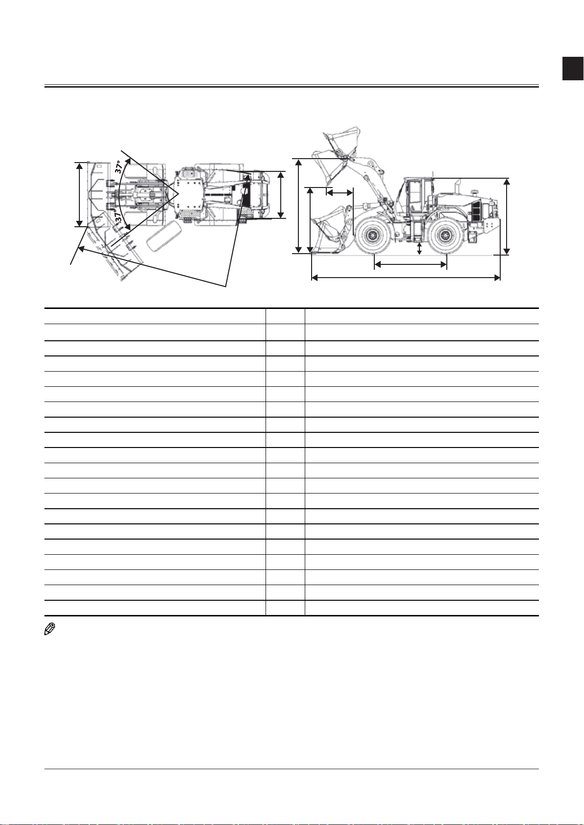
Main Component (Overview)
1
2
3
4
1
9
14
10
11
5
6
7
17
8
13
12
15
16
18
SECTION 1 GENERAL
Group 2 Component Layout
1- Bucket
2- Bucket Link
3- Bell Crank
4- Bucket Cylinder
12- Work Light (Rear)
13- Pre-Cleaner
TNFQ-05-04-019-1 ja
5- Front Combination Light
(Headlight/Turn Signal Light/
Clearance Light/Hazard Light)
6- Horn
7- Work Light (Cab Front)
8- Refer to "Cab"T1-2-8.
9- DEF Tank Box
10- Lift Arm Cylinder
11- Lift Arm
14- Refer to "Battery
Box"T1-2-4.
17- Additional Work Light (Cab
Front)
15- Rear Combination Light (Turn
Signal Light/ Hazard Light/
Tail Light/ Brake Light)
16- Additional Work Light (Cab
Rear)
18- Object Detection Sensor
TNFQ-05-04-020-1 ja
TONFQ50-EN-00(28/02/2022)
T1-2-1
Page 24
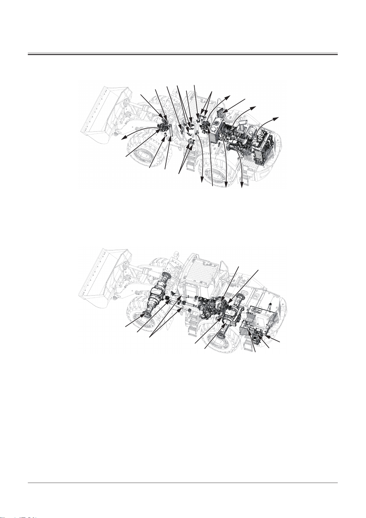
Main Component
11
33
8
41
44
45
36
3
16
20
39
18
42
40
1
37
2
35
32
38
17
30
29
28
24
26
25
31
21
22
1- Refer to "Air Cleaner and Radi
ator Assembly"T1-2-3.
2- Refer to "Aftertreatment De
vice"T1-2-17.
3- Refer to "Hydraulic Oil
Tank"T1-2-5.
8- Steering Accumulator
SECTION 1 GENERAL
Group 2 Component Layout
11- Refer to "Control
Valve"T1-2-19.
16- Refer to "Engine"T1-2-16.
18- Joystick Steering Valve
20- Stop Valve
32- Steering Valve
33- 2-Spool Solenoid Valve Unit
35- Ride Control Valve
36- Refer to"Joystick Steering Sol
enoid Valve Unit"T1-2-25.
37- Axle Oil Cooler
38- Brake Valve
39- Reducing Valve
TNFQ-05-04-021-1 ja
40- Refer to "Brake Charge Valve/
Combination Valve"T1-2-20.
41- Ride Control Accumulator
42- Axle Oil Filter
44- Transmission Oil Filter
45- Joystick Steering Accumulator
17- Refer to "Front Axle"T1-2-7.
22- Refer to "Drive Unit"T1-2-7.
24- Refer to "Fuel Tank"T1-2-6.
TONFQ50-EN-00(28/02/2022)
25- DEF Supply Module
26- DEF Tank
28- Rear Axle
29- Rear Propeller Shaft
30- Front Propeller Shaft
31- Steering Cylinder
T1-2-2
TNFQ-05-04-022-1 ja
Page 25
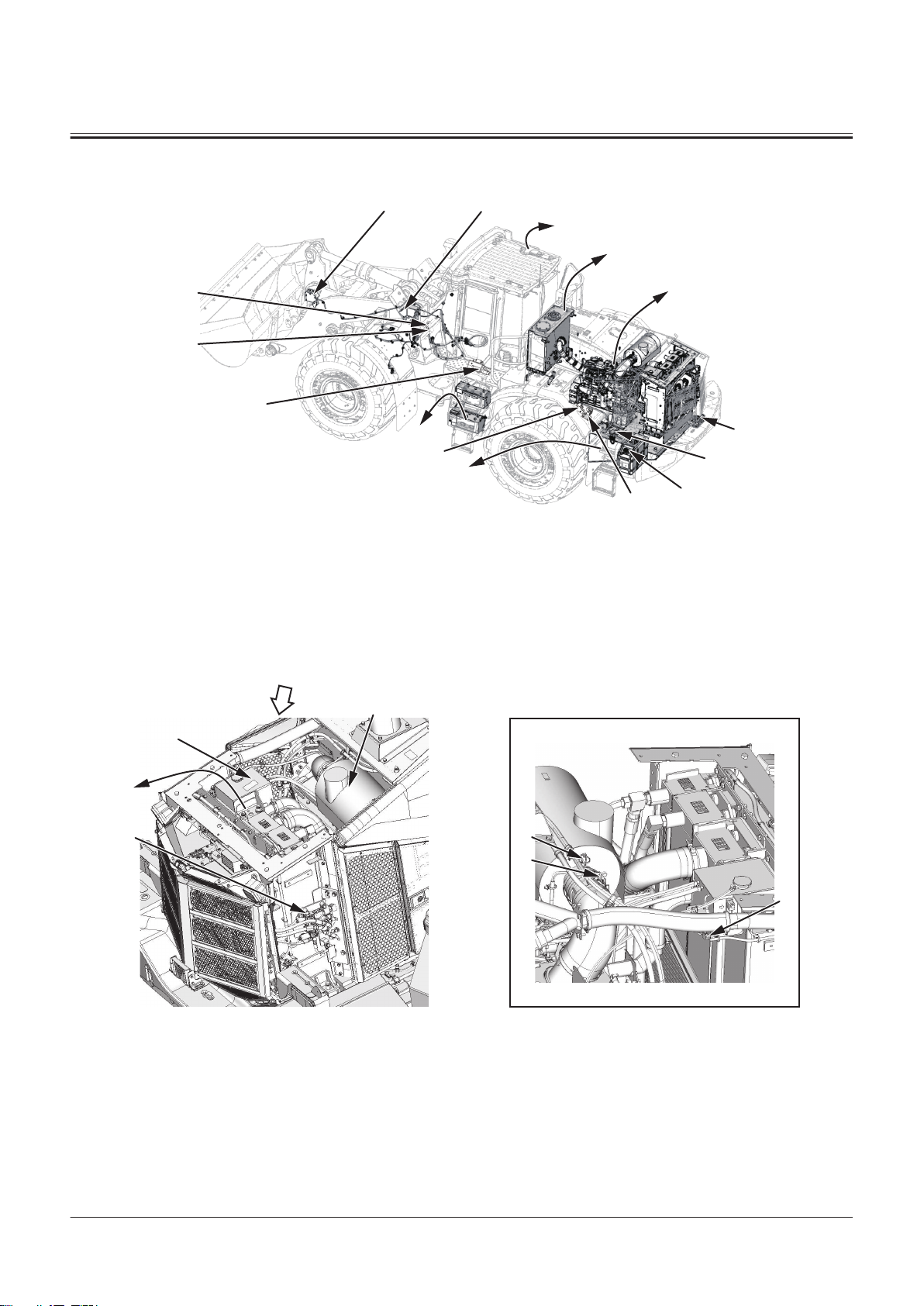
Electrical System (Overview)
46
9
10
8
14
13
12
11
2
3
5
4
1
6
7
A
6
5
7
1
4
2
3
A
1- Refer to "Engine"T1-2-16.
2- Refer to "Hydraulic Oil
Tank"T1-2-5.
3- Refer to "Cab"T1-2-8.
4- Bucket Angle Sensor
5- Lift Arm Angle Sensor
6- Refer to "Battery
7- Refer to "Fuel Tank"T1-2-6.
8- Refer to "DEF Tank"T1-2-23.
SECTION 1 GENERAL
Group 2 Component Layout
9- Back Buzzer
10- Refer to "DEF Supply Mod
Box"T1-2-4.
11- Lift Arm Rod Pressure Sensor
ule"T1-2-24.
TNFQ-05-04-023-1 ja
12- Lift Arm Bottom Pressure Sen
sor
13- Intake-Air Heater Relay
14- Starter Relay 1
46- Refer to "Emergency Steering
Pump Unit"T1-2-23.
Air Cleaner and Radiator Assembly
1- Air Cleaner
2- Refer to "Radiator Assem
bly"T1-2-4.
3- Refer to "Fan Valve"T1-2-17.
4- Expansion Tank
5- TBAP Sensor
6- AIR CLEANER RESTRICTION
SWITCH
7- Coolant Level Switch
TNFQ-05-04-005-1 ja
TONFQ50-EN-00(28/02/2022)
T1-2-3
Page 26
Radiator Assembly
A
1
6
2
3
5
4
A
a
A
10
11
8
9
7
6
5
1
2
3
A
4
SECTION 1 GENERAL
Group 2 Component Layout
TNFQ-05-04-001-1 ja
a- Machine Front Side
1- Expansion Tank
2- Radiator
3- Oil cooler
4- Intercooler
5- Torque Converter Cooler
6- Fan Motor
Battery Box
1- Battery Box
2- Battery
3- Battery Disconnect Switch
4- Battery Disconnect Switch In
5- Battery Relay
dicator Light
6- Fusible Link (30 A)
7- Fusible Link (70 A)
8- Fusible Link (120 A)
9- Fusible Link (120 A)
10- Fusible Link (30 A)
11- Fusible Link (140 A)
TNFQ-05-04-006-1 ja
TONFQ50-EN-00(28/02/2022)
T1-2-4
Page 27

Hydraulic Oil Tank
A
4
2
5
6
3
a
A
1
SECTION 1 GENERAL
Group 2 Component Layout
TNFQ-05-04-007-1 ja
a- Machine Front Side
1- Hydraulic Oil Tank
2- Hydraulic Oil Level Sensor
3- Washer Tank 4- Hydraulic Oil Temperature
Sensor
5- Rear Washer Motor
6- Front Washer Motor
TONFQ50-EN-00(28/02/2022)
T1-2-5
Page 28
Fuel Tank
A
B
4
5
2
3
6
1
B
a
A
SECTION 1 GENERAL
Group 2 Component Layout
TNFQ-05-04-002-1 ja
a- Machine Front Side
1- Fuel Tank
2- Fuel Level Sensor
3- Fuel Pump
4- Fuel Pre-Filter
5- Water Separator Sensor
6- Fuel Main Filter
TONFQ50-EN-00(28/02/2022)
T1-2-6
Page 29
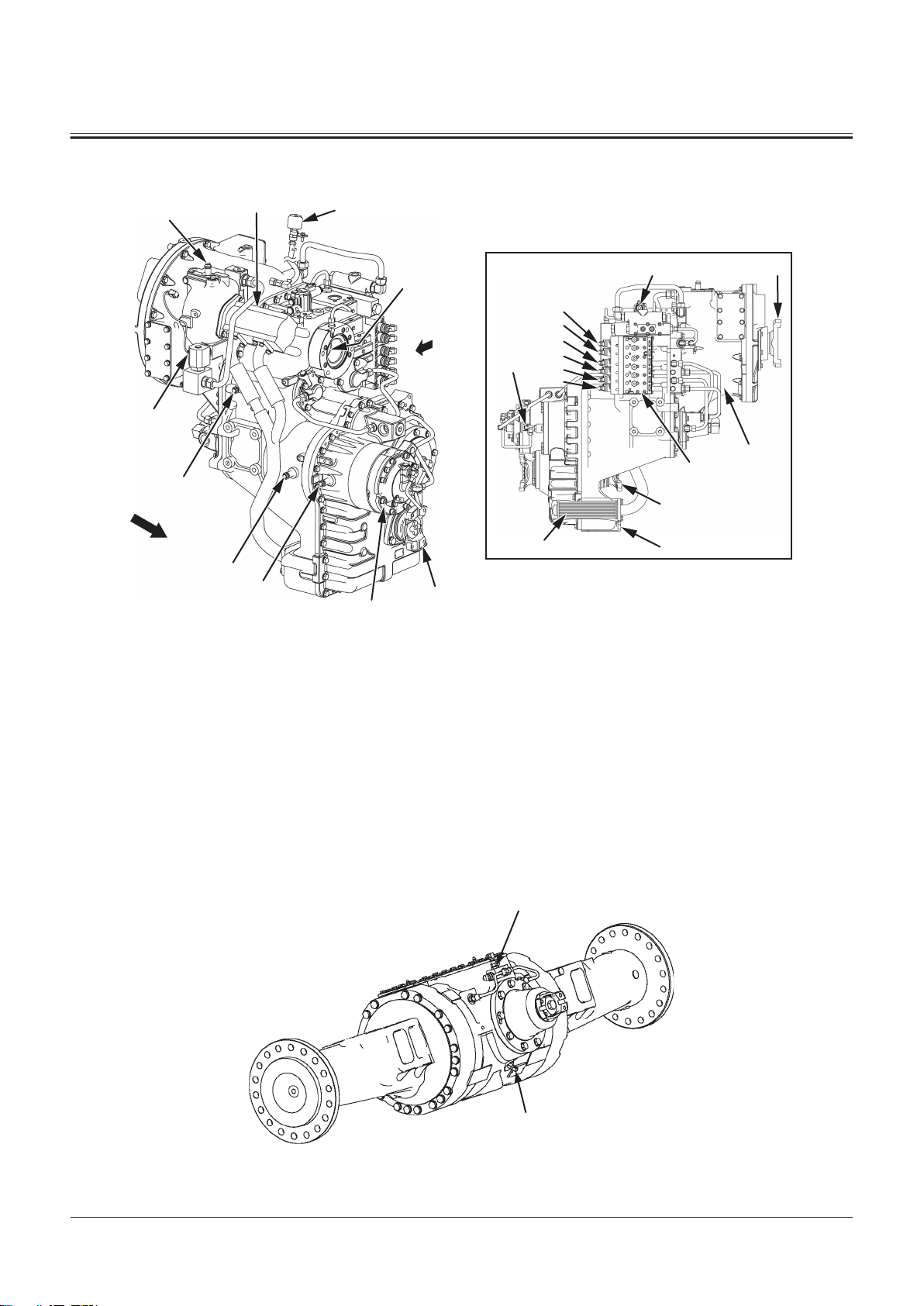
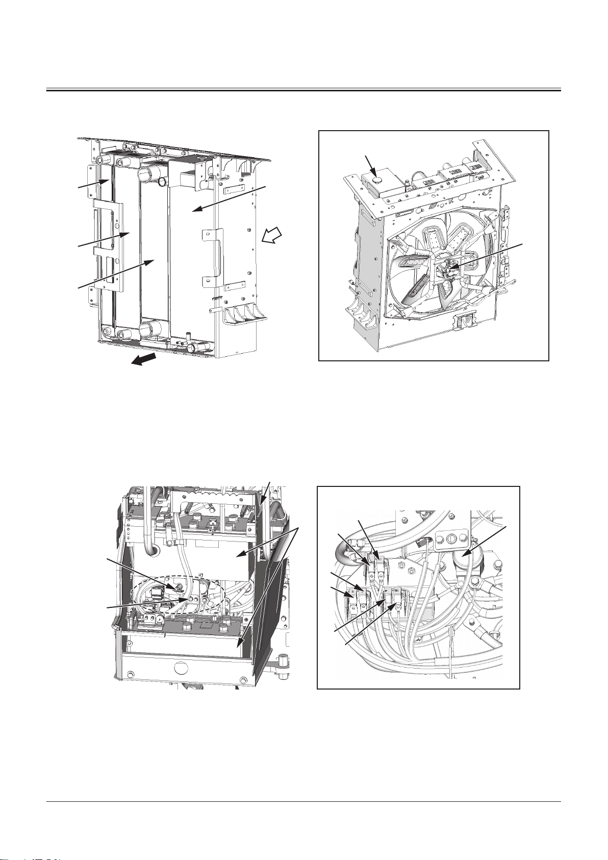
Drive Unit
A
6
2
9
20
8
11
10
4
22
3
A
a
18
21
1
7
23
24
5
19
12
13
14
15
16
17
1
2
SECTION 1 GENERAL
Group 2 Component Layout
a- Machine Front Side
1- Torque Converter
2- Torque Converter Charging
Pump
3- Drive Shaft In Main Pump
4- Parking Brake
5- Strainer
6- Air Breather
7- Transmission Control Valve
8- Torque Converter Output
Shaft Speed Sensor
Front Axle
TNFQ-05-04-025-1 ja
9- Torque Converter Input Shaft
Speed Sensor
10- Vehicle Speed Sensor
11- Transmission Intermediate
Shaft Speed Sensor
12- Forward Clutch Solenoid
Valve
13- Reverse Clutch Solenoid Valve
14- First Speed Clutch Solenoid
Valve
15- Second Speed Clutch Sole
noid Valve
16- Third Speed Clutch Solenoid
Valve
17- Fourth Speed Clutch Solenoid
Valve
18- Lock Up Clutch Solenoid
Valve
19- Parking Brake Pressure Sensor
20- Transmission Oil Temperature
Sensor
21- Flange (For Main Propeller
Shaft)
22- Flange (For Front Propeller
Shaft)
23- Flange (For Rear Propeller
Shaft)
24- Drain Port
1- Service Brake Secondary Pres
sure Sensor
TONFQ50-EN-00(28/02/2022)
2- Axle Oil Temperature Sensor
T1-2-7
TNEE-01-02-018-1 ja
Page 30
Cab
A
B
D
E F
13141011
12
16
15
9
18
b
E
D
e
c
3
8
2
1
1
B
A
a
e
7
6
4
17
5
F
SECTION 1 GENERAL
Group 2 Component Layout
a- (Refer to "Front Console"T1-2-9.) c- (Refer to "Rear Console"T1-2-13.)
b- (Refer to "Right Console"T1-2-11.) e- (Refer to "Control Unit"T1-2-14.)
TONFQ50-EN-00(28/02/2022)
TNUD-01-02-105-1 ja
T1-2-8
Page 31
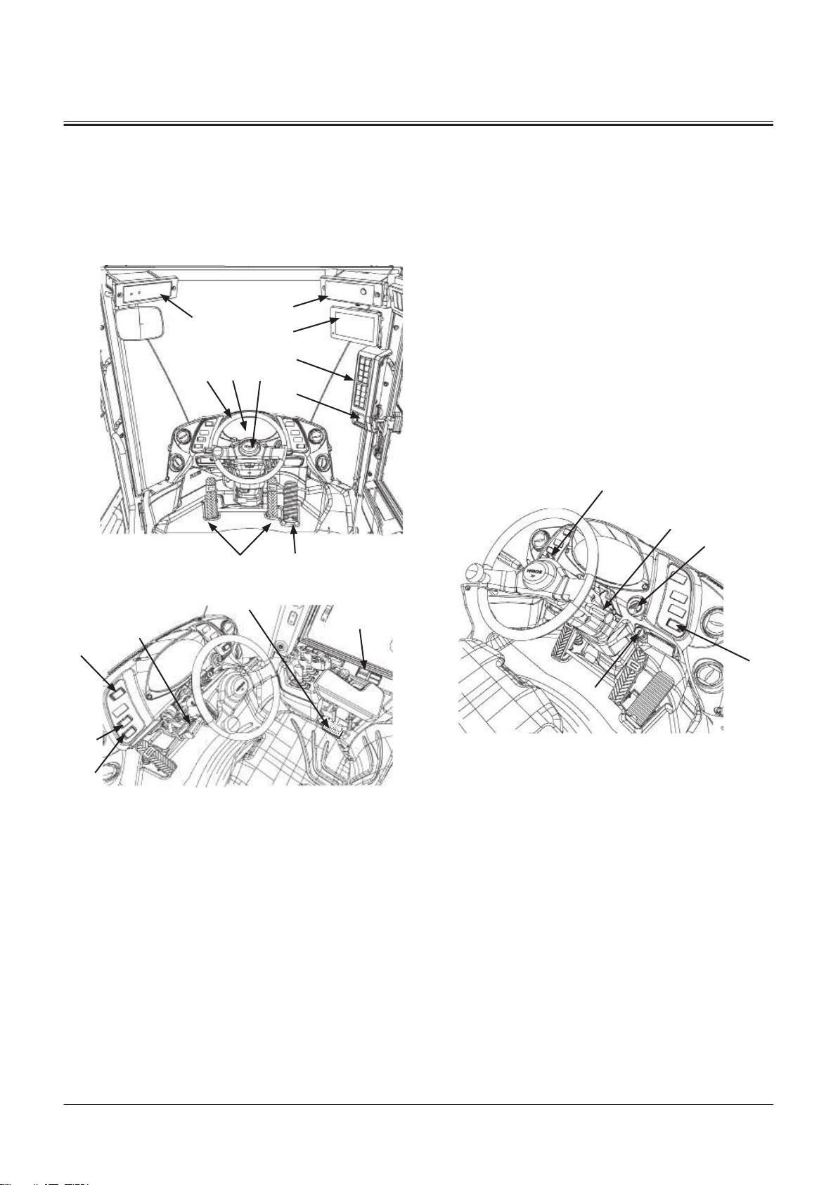
7
8
2 3 4
5
6
17
13
20
9
21
12
10
1
18
22
15
14
16
19
SECTION 1 GENERAL
Group 2 Component Layout
1- Speaker
2- Satellite Communication An
tenna
3- Upper Switch Panel
4- Rear Wiper Motor
Front Console
5- Radio
6- Accelerator Pedal Sensor
7- Brake Pedal Position Sensor
8- Cab Light
9- Brake Pedal Switch
10- Front Wiper Relay 2
11- Front Wiper Relay 1
12- Auto Shut-Down Relay
13- Key Switch ON Cut Relay
14- ACC Cut Relay
15- Front Wiper Motor
16- Mirror Heater Relay
17- Beacon Light
18- Beacon Light Switch
1- Neutral Lever Lock for For
ward/Reverse Lever
2- Steering Wheel
3- Refer to"Column Moni
tor"T1-2-15.
4- Horn Switch
5- Radio
6- Sub Monitor
7- Panel Switch
8- Rear View Mirror Angle Ad
justment Switch
9- 24 V Power Supply Socket
10- Emergency Steering Check
Switch
12- Accelerator Pedal
13- Brake Pedal
14- Hazard Switch
15- Work Light Switch
16- Parking Switch
17- Air Conditioner Control Panel
18- USB Power Source
TNUD-01-02-106-1 ja
19- Forward/Reverse Lever, Shift
Switch
20- Turn Signal Lever, Light
Switch, Dimmer Switch
21- Key Switch
22- Seat Belt Switch
TONFQ50-EN-00(28/02/2022)
T1-2-9
Page 32
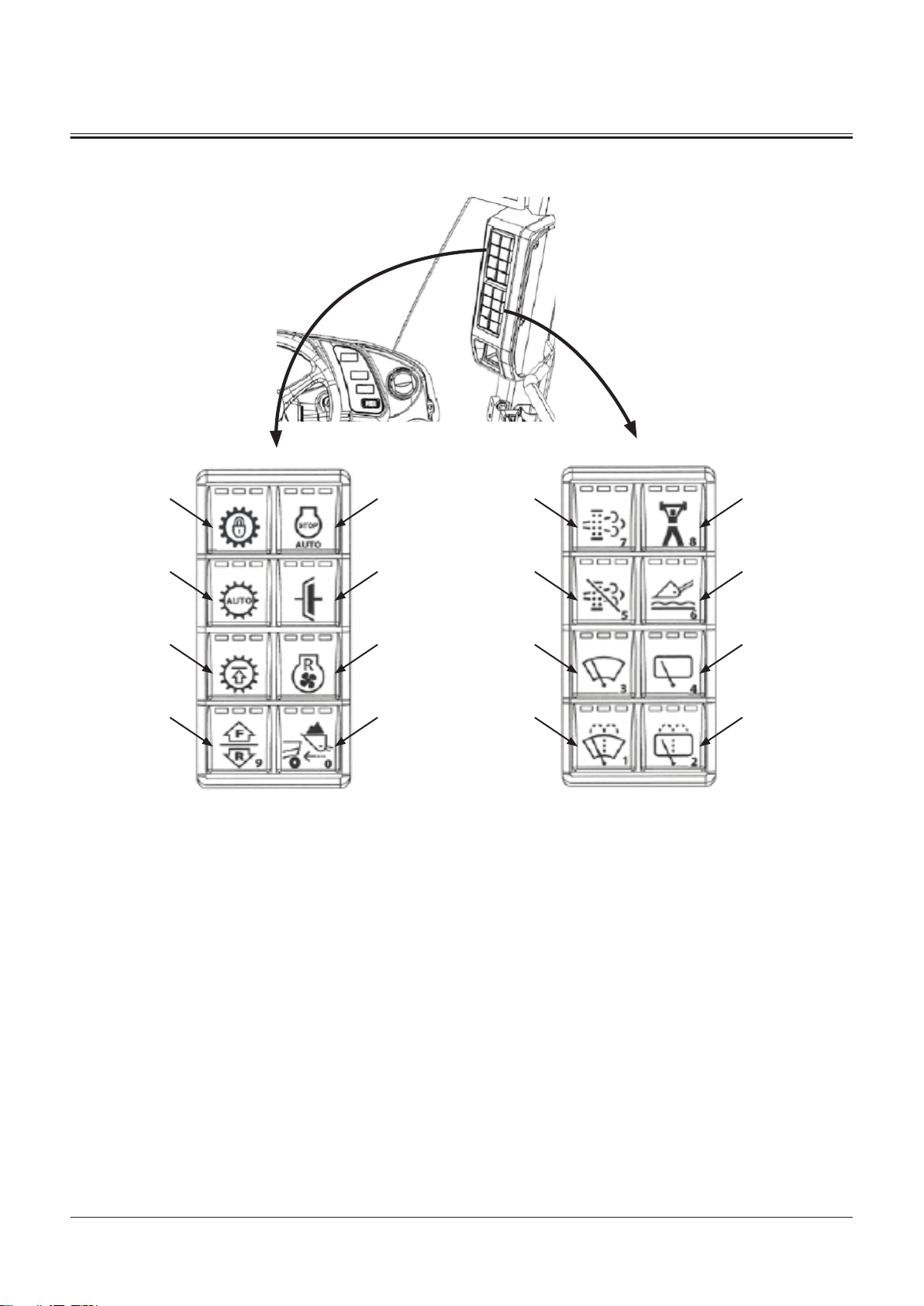
Panel Switch
8 161
6 143 11
7 152 10
9
5 134 12
SECTION 1 GENERAL
Group 2 Component Layout
1- Auto Shut-Down Switch
2- Clutch Cut Position Switch
3- Fan Reverse Rotation Switch
4- Dump Approach Mode Selec
tor Switch
5- Forward/Reverse Selector
Switch
6- Gear Restriction Switch
7- Travel Mode Switch
8- Lock Up Switch
9- Power Mode Switch
10- Ride Control Switch
11- Rear Wiper Switch
12- Rear Washer Switch
13- Front Washer Switch
TONFQ50-EN-00(28/02/2022)
T1-2-10
TNFQ-05-04-024-1 ja
14- Front Wiper Switch
15- Regeneration Inhibit Switch
16- Manual Regeneration Switch
Page 33
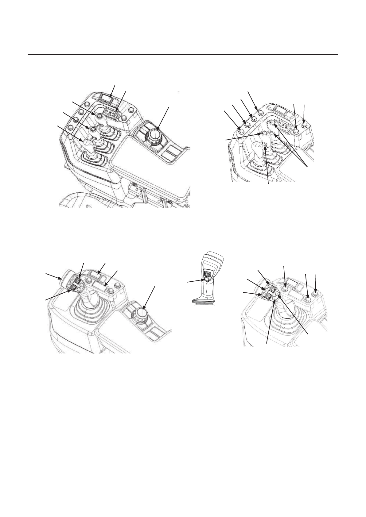
Right Console
12
11
10
9
6
5
4
3
2
1
17
16
15
14 13
6
8
4
19
18
5
9
10
11
12
15
16
14 13
17
SECTION 1 GENERAL
Group 2 Component Layout
Fingertip Control Lever Type
TNUD-01-02-108-2 ja
1- Auxiliary 1 Control Lever
2- Bucket Control Lever
3- Lift Arm Control Lever
4- Control Lever Lock Switch
5- Forward/Reverse Switch
6- Rotary Device
9- Load cancel Switch
10- Tip O Selector Switch
11- Track Clear Switch
12- Add Load Switch
13- Hold Switch
14- Mist Switch
15- Downshift Switch
16- Quick Power Switch
17- Horn Switch
Multi-Function Joystick Lever Type
TNUD-01-02-109-2 ja
4- Control Lever Lock Switch
5- Forward/Reverse Switch
6- Rotary Device
9- Load cancel Switch
10- Tip O Selector Switch
11- Track Clear Switch
12- Add Load Switch
13- Hold Switch
14- Mist Switch
15- Downshift Switch
16- Quick Power Switch
17- Horn Switch
18- Multi Function Joystick Lever
19- Auxiliary 1 Control Switch (For
Third Spool)
TONFQ50-EN-00(28/02/2022)
T1-2-11
Page 34
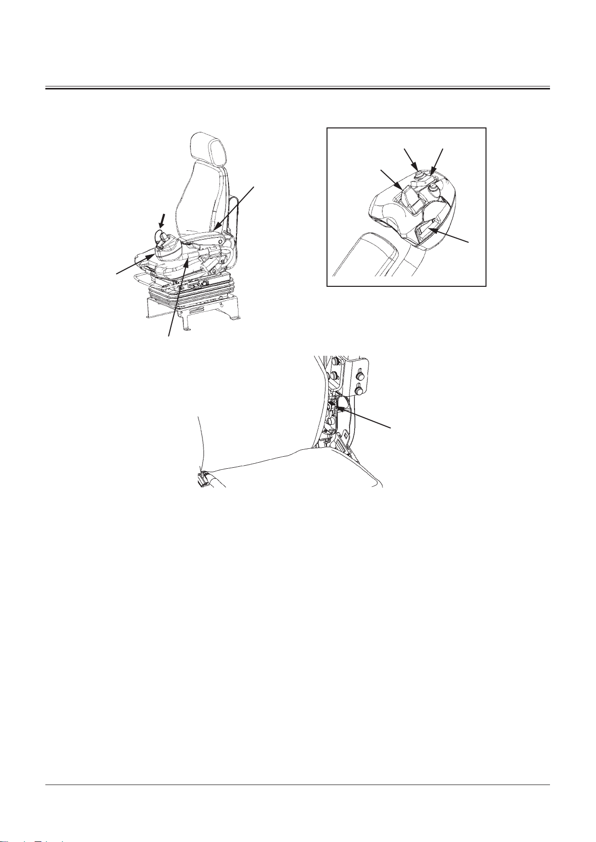
3
A
1
2
54
8
7
9
A
SECTION 1 GENERAL
Group 2 Component Layout
Operator's Seat and Joystick Steering System
1- Switch Box
2- Left Console Pipe
3- Left Armrest
4- Downshift Switch
5- Forward/Reverse Switch (JSS)
7- Joystick Steering Selector
8- Joystick Steering Lever
Switch
9- Left Console Lock Release
Lever
TNUD-01-02-110-2 ja
TONFQ50-EN-00(28/02/2022)
T1-2-12
Page 35
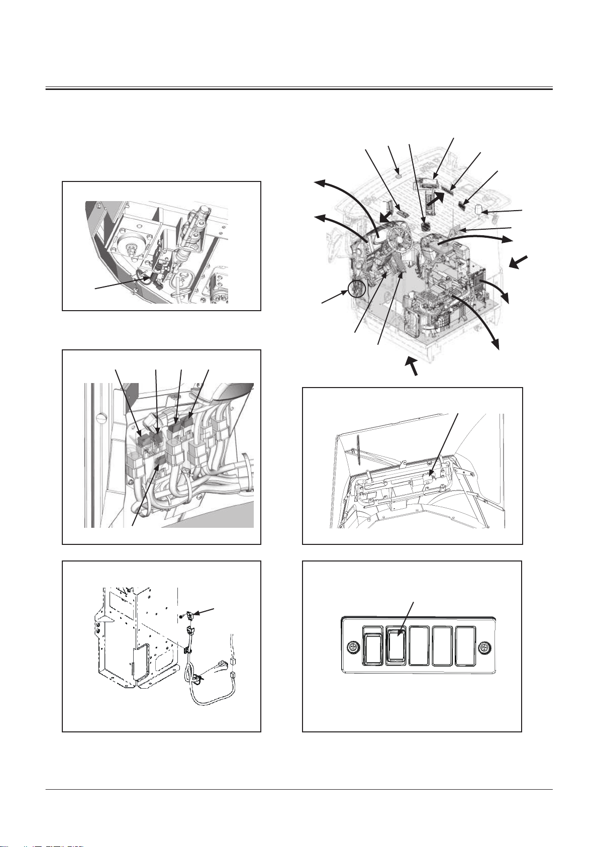
Rear Console
A
B
E
8
9
10
1
2 3 4 5
32
33
40
35
31
a
39
39
38
37
36
7
6
1211
27
17
26
16
2221
13
28
18
23
14
29
19
24
15
30
20
25
B
A
E
31
37
41
SECTION 1 GENERAL
Group 2 Component Layout
TONFQ50-EN-00(28/02/2022)
TNUD-01-02-111-2 ja
T1-2-13
Page 36

a- Machine Front Side
A
D
B
4
68
5
7
3
2
b
a
a
1
A
D
B
SECTION 1 GENERAL
Group 2 Component Layout
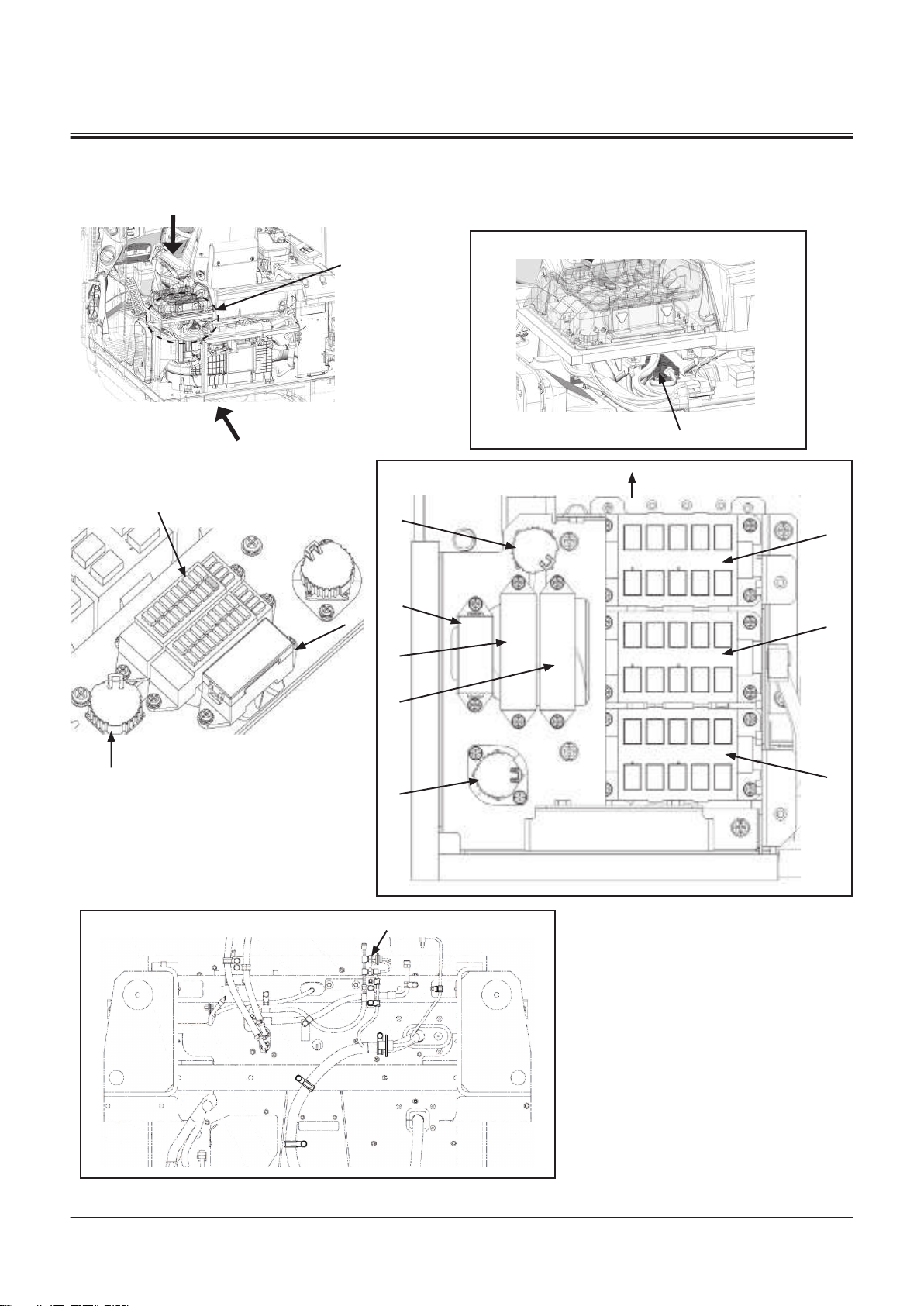
1- Back Buzzer Relay (A-R5)
2- Not Used
3- High Beam Relay (A-R3)
4- Headlight Relay (Right) (A-R2)
5- Headlight Relay (Left) (A-R1)
6- Starter Cut Relay (A-R10)
7- Horn Relay (A-R9)
8- Turn Signal Light Relay (Right)
(A-R8)
9- Work Light Relay (Rear) (A-R7)
10- Work Light Relay (Front) (A-
R6)
Control Unit
11- Load Dump Relay (B-R5)
12- Brake Light Relay (B-R4)
13- PLCU Relay (B-R3)
14- Parking Brake Relay 2 (B-R2)
15- Parking Brake Relay 1 (B-R1)
16- Rear Washer Relay (B-R10)
17- Rear Wiper Relay (B-R9)
18- Front Washer Relay (B-R8)
19- Turn Signal Light Relay (Left)
(B-R7)
20- Neutral Relay (B-R6)
21- DEF Heater Relay 3 (C-R5)
22- DEF Heater Relay 2 (C-R4)
23- DEF Heater Relay 1 (C-R3)
24- SCR Sensor Relay (C-R2)
25- DEF Supply Module Relay (C-
R1)
26- Additional Work Light Relay
(Cab Front) (C-R10)
27- Additional Work Light Relay
(Cab Rear) (C-R9)
28- Not Used
29- Not Used
30- Beacon Light Relay (C-R6)
31- MPDr. Connector
32- Relay Box A
33- Relay Box B
35- Relay Box C
36- Engine Diagnostic Connector
37- Fuse Box A
38- Fuse Box B
39- Fuse Box C
40- Position Sensor
41- Pressure Sensor (Refrigerant
Pressure)
a- Machine Front Side b- Main Monitor
TONFQ50-EN-00(28/02/2022)
T1-2-14
TNUD-01-02-112-1 ja
Page 37
1
32
33
34
35
36
37 38
2 3 4
5
6
7
8
9
10
11
12
13
14
15
24252627 1923 394041 1822 1721 20 16
31
29
30
28
SECTION 1 GENERAL
Group 2 Component Layout
1- Air Conditioner Controller
2- Monitor Controller
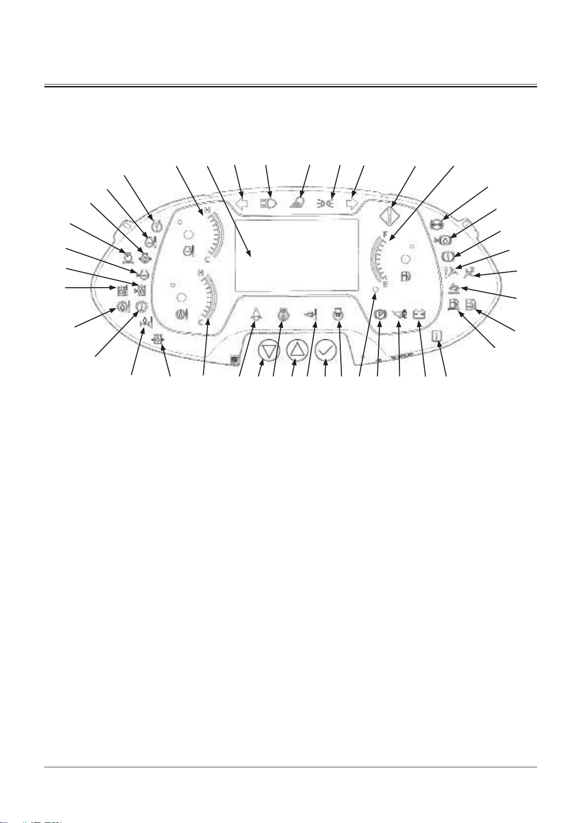
Column Monitor
3- TCU
4- MC
5- PLCU
6- Aerial Angle Controller
7- GSM/GPS
8- Flasher Relay
1- Left Turn Signal Light Indica
tor
2- High Beam Indicator
3- Work Light Indicator
4- Clearance Light Indicator
5- Right Turn Signal Light Indica
tor
6- Service Indicator
7- Fuel Gauge
8- Brake Oil Pressure Indicator
9- Brake Oil Level Indicator
10- Not Used
11- Steering Oil Pressure Indicator
12- Emergency Steering Indicator
13- Urea Alarm
14- Water Separator Indicator
15- Fuel Filter Restriction Indica
tor
16- Communication System Error
Indicator
17- Discharge Warning Indicator
18- Control Lever Lock Indicator
19- Parking Brake Indicator
20- Fuel Level Indicator
21- Preheat Indicator
22- Aftertreatment Device Indica
tor
23- Fan Reverse Rotation Indica
tor
24- Seat belt Indicator
25- Transmission Oil Temperature
Gauge
26- Main Pump Oil Pressure Indi
cator
27- Axle Oil Temperature Indica
tor
28- Transmission Warning Indica
tor
29- Transmission Oil Temperature
Indicator
TNUD-01-02-113-1 ja
30- Hydraulic Oil Temperature In
dicator
31- Hydraulic Oil Level Indicator
32- Coolant Level Indicator
33- Air Filter Restriction Indicator
34- Engine Oil Pressure Indicator
35- Overheat Indicator
36- Engine Trouble Indicator
37- Coolant Temperature Gauge
38- Main Monitor
39- Select/Conrm Button
40- Up Button
41- Down Button
TONFQ50-EN-00(28/02/2022)
T1-2-15
Page 38

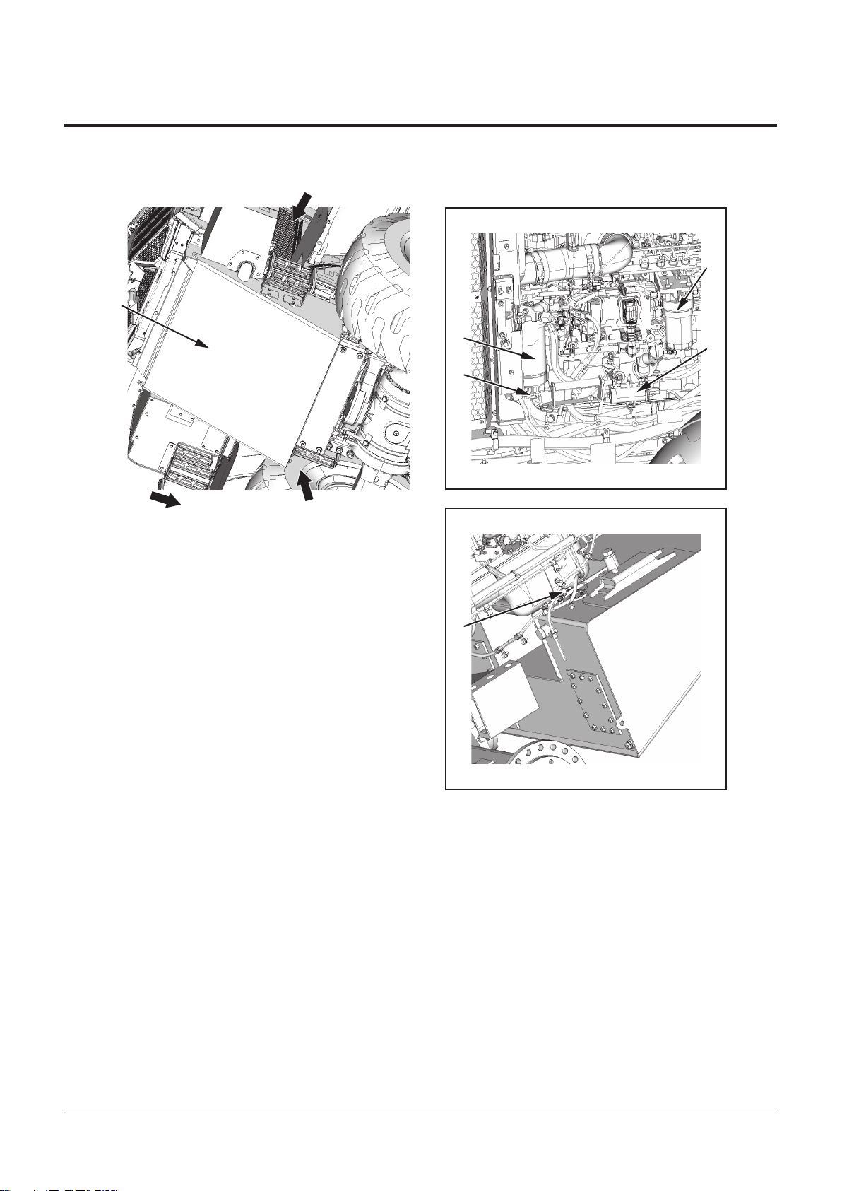
Engine
1
2
3
9
11
12
14
13
10
15
8
7
6
5
4
SECTION 1 GENERAL
Group 2 Component Layout
1- Crankcase Pressure Sensor
2- Supply Pump
3- Cam Angle Sensor
4- Boost Pressure/Temperature
Sensor
5- Common Rail Pressure Sensor
6- Fuel Main Filter
7- Crank Speed Sensor
8- Oil Pressure Switch
9- ECM
10- Exhaust Pressure Sensor
11- Alternator
12- Coolant Temperature Sensor
13- Starter
14- Engine Oil Filter
TNFQ-05-04-033-1 ja
15- Vibration Damper
TONFQ50-EN-00(28/02/2022)
T1-2-16
Page 39
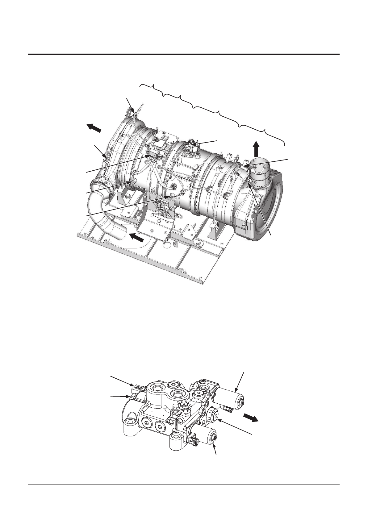
Aftertreatment Device
1
9
10
11
12
8
6
7
5
2
4
3
a
5
4
a
1
3
2
SECTION 1 GENERAL
Group 2 Component Layout
TNFQ-05-04-010-1 ja
a- Machine Front Side
1- Upstream NOx Sensor
2- Dosing Module
3- Downstream NOx Sensor
4- SCR Outlet Exhaust Tempera
Fan Valve
ture Sensor
5- SCR Inlet Exhaust Tempera
ture Sensor
6- Dierential Pressure Sensor
7- DOC Outlet Exhaust Tempera
ture Sensor
8- DOC Inlet Exhaust Tempera
ture Sensor
9- DOC (Diesel Oxidation Cata
lyst)
10- Filter (CSF)
11- Mixer Module
12- SCR Catalyst
TNEE-01-02-031-2 ja
TONFQ50-EN-00(28/02/2022)
T1-2-17
Page 40
a- Machine Front Side
7
10
9
2
1
8
a
SECTION 1 GENERAL
Group 2 Component Layout
1- Fan Speed Control Solenoid
Valve
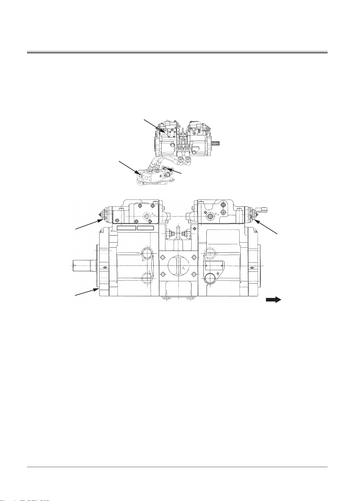
Pump Device
2- Fan Reverse Rotation Control
Solenoid Valve
3- Fan Control Valve
4- Fan Reverse Rotation Spool
5- Fan Circuit Pressure Sensor
TNFQ-05-04-026-1 ja
a- Machine Front Side
1- Main Pump
2- Regulator 1
TONFQ50-EN-00(28/02/2022)
7- Torque Control Solenoid Valve
8- Regulator 2
9- Steering Pressure Switch 10- Pump Delivery Pressure Sen
sor
T1-2-18
Page 41
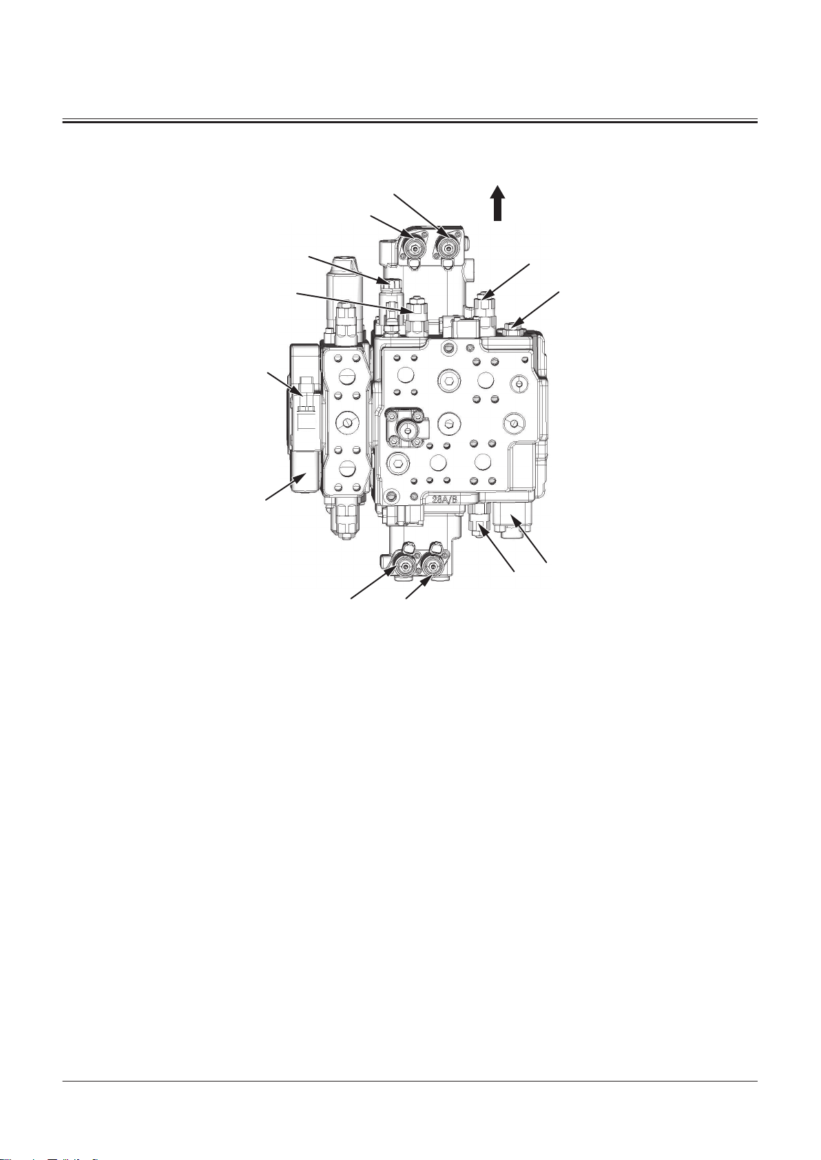
Control Valve
3
1
a
6
2
11
7
12
10
4
5
9
8
SECTION 1 GENERAL
Group 2 Component Layout
a- Machine Front Side
1- Main Relief Valve
2- Overload Relief Valve (Bucket:
Rod Side)
3- Overload Relief Valve (Bucket:
Bottom Side)
12 Negative Control Pressure
Sensor
4- Overload Relief Valve (Lift
Arm: Rod Side)
5- Ride Control Selector Sole
noid Valve
6- Bleed O Compensator
TNFQ-05-04-013-1 ja
7- Pump Flow Rate Control Valve
8- Bucket Dump Solenoid Valve
9- Lift Arm Raise Solenoid Valve
10- Bucket Tilt Solenoid Valve
11- Lift Arm Lower Solenoid Valve
TONFQ50-EN-00(28/02/2022)
T1-2-19
Page 42
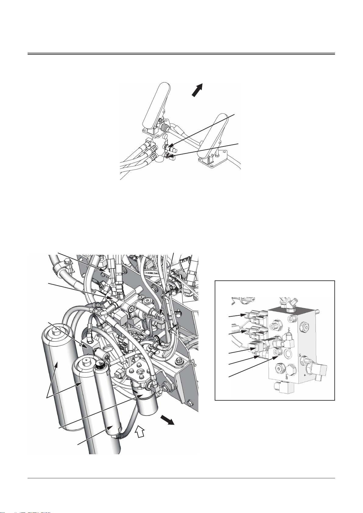
Brake Valve
2
1
a
A
a
A
11
1
2
3
4
12
10
6
7
8
9
5
a- Machine Front Side
SECTION 1 GENERAL
Group 2 Component Layout
TNFQ-05-04-029-1 ja
1- Brake Oil Pressure Switch 2- Service Brake Secondary Pres
sure Sensor
Brake Charge Valve/Combination Valve
TONFQ50-EN-00(28/02/2022)
T1-2-20
TNFQ-05-04-017-1 ja
Page 43

a- Machine Front Side
1
2
3
2
a
SECTION 1 GENERAL
Group 2 Component Layout
1- Brake Charge Valve
2- Service Brake Primary Pres
sure Sensor
3- Lift Arm Flow Rate Control
Solenoid Valve
Steering Valve
4- Service Brake Accumulator
5- Combination Valve
6- Parking Brake Solenoid Valve
7- Control Lever Lock Solenoid
Valve
8- Primary Pilot Pressure Sensor
9- Reducing Valve
10- Parking Brake Accumulator
11- Flow Combiner Control Valve
12- Pilot Filter
TNFQ-05-04-016-1 ja
a- Machine Front Side
1- Steering Main Relief Valve 2- Steering Overload Relief Valve 3- Emergency Steering Pump
Delivery Pressure Sensor
TONFQ50-EN-00(28/02/2022)
T1-2-21
Page 44
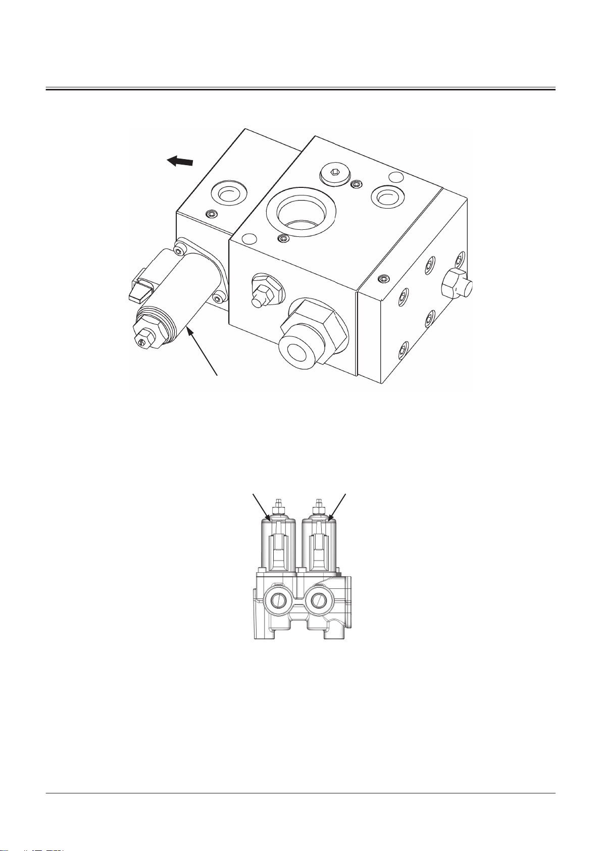
Ride Control Valve
1
a
A2 A1
SECTION 1 GENERAL
Group 2 Component Layout
a- Machine Front Side
1- Ride Control Solenoid Valve
2-Spool Solenoid Valve Unit
A2- Auxiliary 1 Solenoid Valve A1- Auxiliary 2 Solenoid Valve
TNFQ-05-04-028-1 ja
TNUD-01-02-020-2 ja
TONFQ50-EN-00(28/02/2022)
T1-2-22
Page 45
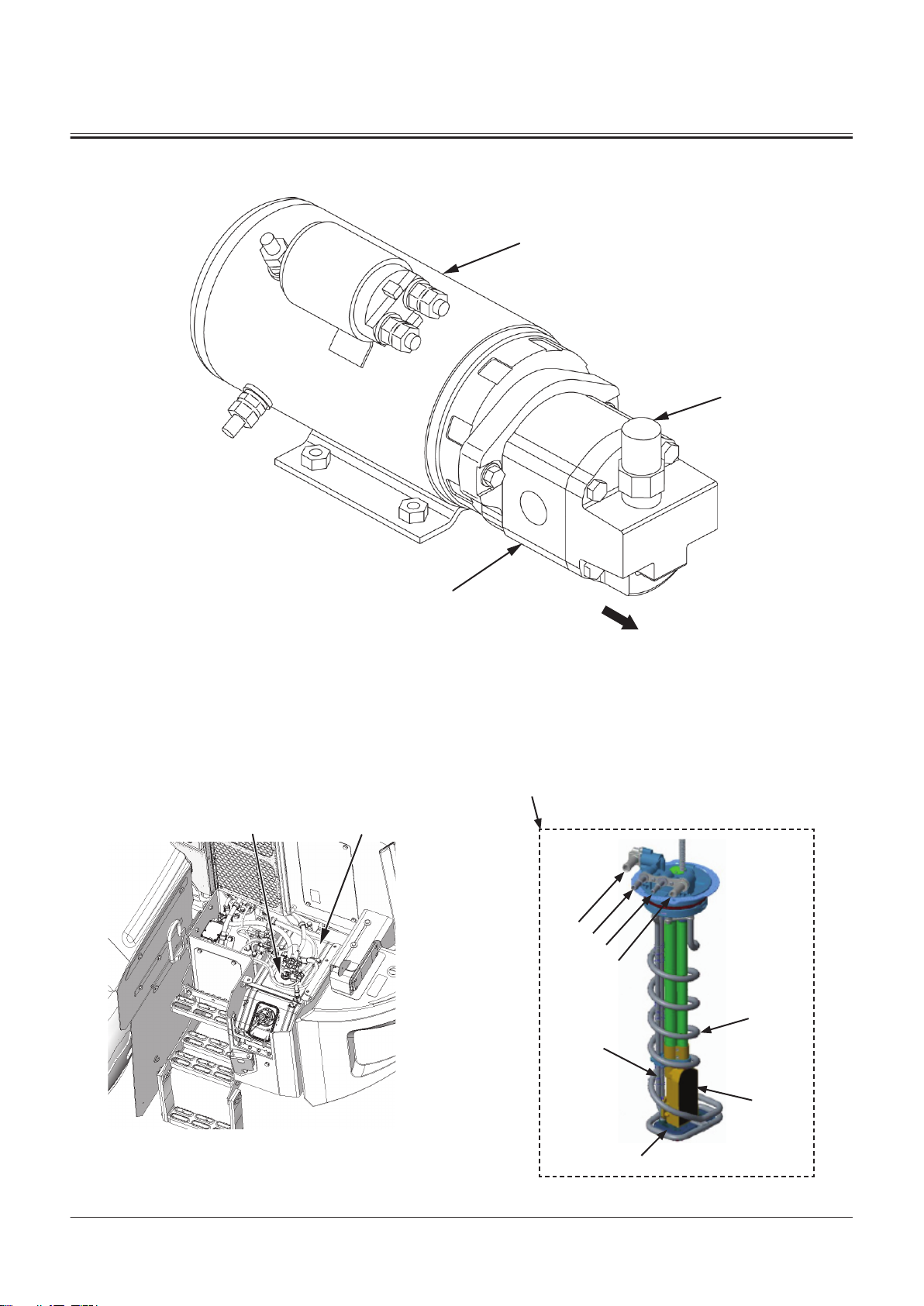
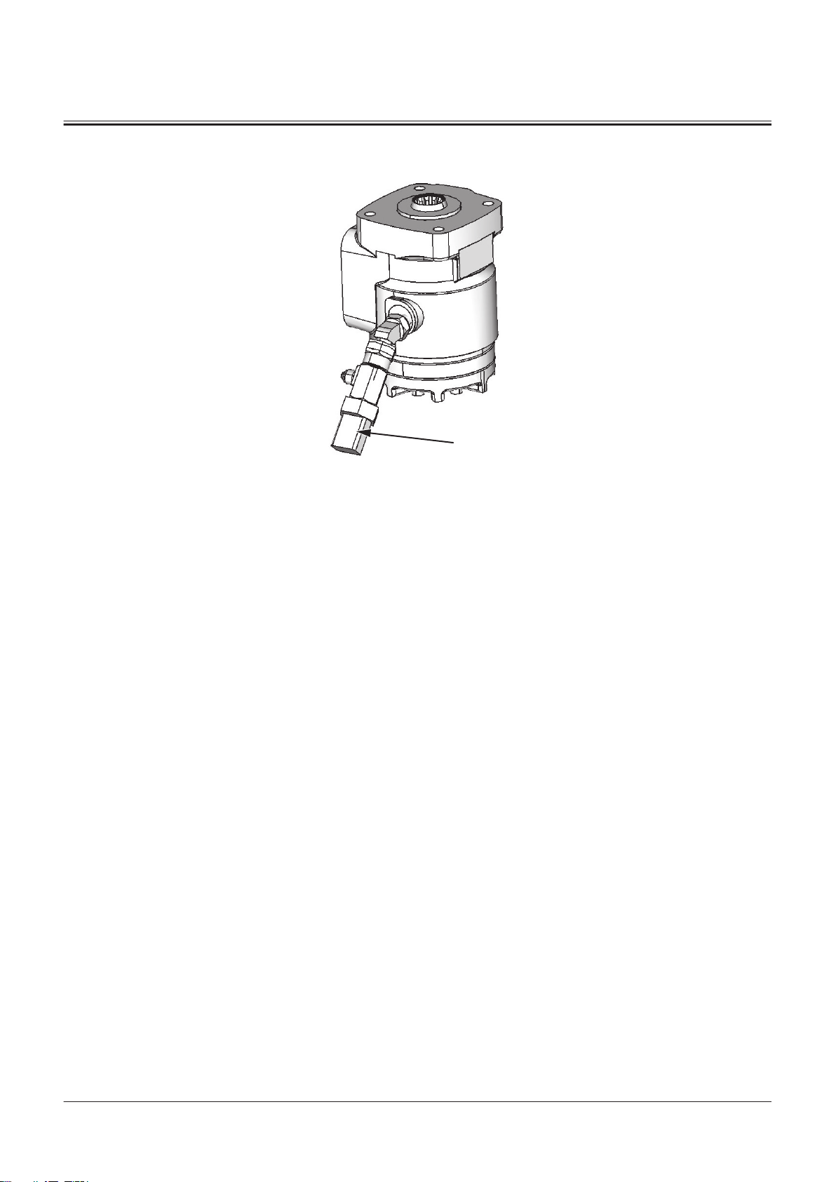
Emergency Steering Pump Unit
1
3
2
a
2
1
6
7
8
9
10
1
3
4
5
SECTION 1 GENERAL
Group 2 Component Layout
a- Machine Front Side
1- Relief Valve 2- Emergency Steering Pump 3- Emergency Steering Motor
DEF Tank
TNFQ-05-04-027-1 ja
TONFQ50-EN-00(28/02/2022)
T1-2-23
TNFQ-05-04-003-1 ja
Page 46
11 5, 6 7 8 9 10 11
1
6
5
42
3
10
7
3
4
6
5
2
1
9
8
a
SECTION 1 GENERAL
Group 2 Component Layout
1- DEF Sensor Unit
2- DEF Tank
3- Coolant Heater Tube
4- DEF Tank Level/DEF Tank
Temperature/DEF Quality
Sensor
DEF Supply Module
5- DEF Suction Filter
6- DEF Suction Tube
7- Coolant Port (To DEF Supply
Module)
8- DEF Port (From Dosing Mod
ule)
9- DEF Port (To DEF Supply Mod
ule)
10- Coolant Port (From Coolant
Control Valve)
TNFQ-05-04-004-1 ja
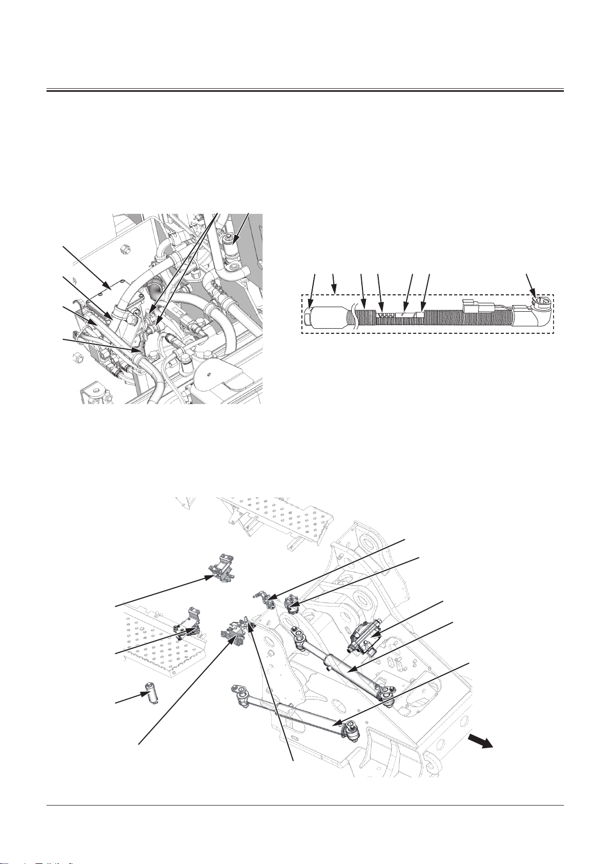
1- DEF Supply Module
2- DEF Hose
3- DEF Supply Module Main Fil
ter
4- Coolant Control Valve
5- DEF Hose
6- DEF Hose
7- Corrugate Tube
8- DEF Tube
9- Heating Wire
10- Thermoplastic Cover
11- Quick Connector
Joystick Steering Hydraulic Component
TONFQ50-EN-00(28/02/2022)
T1-2-24
TNFQ-05-04-018-1 ja
Page 47
1
3
4
A
5
B
SECTION 1 GENERAL
Group 2 Component Layout
1- Refer to "Steering
Valve"T1-2-21.
2- Refer to "Steering Pilot
Valve"T1-2-26.
3- Refer to "Joystick Steering
Valve"T1-2-25.*)
4- Refer to "Joystick Steering Sol
enoid Valve Unit"T1-2-25.*)
5- Stop Valve (Left)
6- Stop Valve (Right)
7- Joystick Steering Accumulator
8- Steering Cylinder (Right)
9- Steering Cylinder (Left)
10- Reducing Valve
NOTE
*
The component is an optional hydraulic component included with the joystick steering specication.
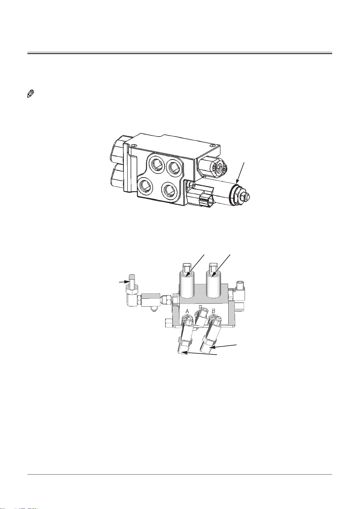
Joystick Steering Valve
1- Cuto Solenoid Valve
Joystick Steering Solenoid Valve Unit
TNUD-01-02-117-1 ja
TNFQ-05-04-031-1 ja
A- Right Steering Solenoid Valve B- Left Steering Solenoid Valve
3- Pilot Pressure Sensor for
Steering (Left)
TONFQ50-EN-00(28/02/2022)
4- Pilot Pressure Sensor for
Steering (Right)
5- Steering Source Pressure Sen
sor
T1-2-25
Page 48
Steering Pilot Valve
1
1- Steering LS Pressure Sensor
SECTION 1 GENERAL
Group 2 Component Layout
TNFQ-05-04-032-1 ja
TONFQ50-EN-00(28/02/2022)
T1-2-26
Page 49

SECTION 1 GENERAL
Group 3 Component Specifications
Specications of Engine
Manufacturer Cummins Inc.
Model L9
Type Diesel, 4-Cycle, 6-Cylinder, Vertical Type, Water-cooled, Direct Injection Type, w/ Super
charger, Intake Air Cooling Type
Cyl. No.- Bore × Stroke 6-114 mm × 145 mm
Total Displacement
Rated Output (gross)
Dry Weight 753 kg
Firing Order 1-5-3-6-2-4
Rotating Direction Counterclockwise Viewed From Flywheel Side
Dimensions: Overall Length ×
Overall Width × Overall Height
8900 cm
213 kW/2000 min
1130 × 931 × 1108 mm
3
-1
TONFQ50-EN-00(28/02/2022)
T1-3-1
Page 50

SECTION 1 GENERAL
Group 3 Component Specifications
Cooling System Cooling Fan Dia. 850 mm, 6 Hybrid Blades
Thermostat Cracking Temperature at Atmospheric Pressure: 82 °C
Full Open: 94 °C
Water Pump Centrifugal Type
Lubrication System Type of Lubrication Pump Trochoid Type
Oil Filter Strata Pore (Plastic ber)/Spin-on Type
Oil Cooler Water Cooled Type
Starting System Electrical Motor Electromagnetic Pinion Shift Reduction Type
Voltage/Output 24 V/7.8 kW
Preheat System Type Grid Air Heater (24 V/100 A)
Engine Stop System Type Fuel Shut-O (Electronic Control)
Alternator Type AC Type
Voltage/Output 24 V/95 A
Supercharging System Type Exhaust-Turbocharger Type, Forced Lubrication
Fuel System Type Common Rail Type, HPCR Type
Governor Electronic All Speed Control
Injection Nozzle Electrical Multi-Hole Injector
Fuel Filter Nanonet (Plastic ber)/Spin-on Type
TONFQ50-EN-00(28/02/2022)
T1-3-2
Page 51

SECTION 1 GENERAL
Group 3 Component Specifications
IMPORTANT
This table shows design specications, which are not servicing standards.
Performance (New Parts) Fuel Consumption Rate
Maximum Output Torque
(Gross)
No Load Speed
Valve Clearance (Intake/
Exhaust)
219⁺¹¹₀ g/kW·h/(Full Load: 2000 min-1)
1636⁺⁸²₀ N·m at 1100 min
Slow: 800±30 min
Fast: 2100±30 min
0.305/0.559 mm (When Cold)
-1
-1
-1
TONFQ50-EN-00(28/02/2022)
T1-3-3
Page 52
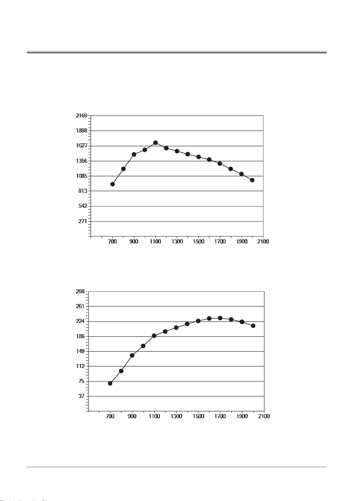
N
T
min
-1
N•m
N
kW
P
min
-1
SECTION 1 GENERAL
Group 3 Component Specifications
Engine Performance Curve (L9)
Test Condition:
1. In accordance with SAEJ 1995 conditions (measurement of engine power and measurement method) under standard
atmospheric pressure.
2. Equipped with alternator. Without fan.
TNFQ-01-03-001-1 ja
T: Torque N: Engine Speed
P: Output N: Engine Speed
TONFQ50-EN-00(28/02/2022)
T1-3-4
TNFQ-01-03-002-1 ja
Page 53

N
g/kW・h
q
min
-1
SECTION 1 GENERAL
Group 3 Component Specifications
q: Fuel Consumption Rate N: Engine Speed
TNFQ-01-03-003-1 ja
Specications of Engine Accessories
Radiator Assembly Type Radiator, Oil Cooler and Intercooler Parallel Type Assembly,
Torque Converter Cooler Tandem Type Assembly
Radiator Oil cooler
Airtight Test Pressure 0.22 MPa 2.25 MPa
Intercooler Torque Converter Cooler
Airtight Test Pressure 0.3 MPa 2.25 MPa
Expansion Tank Total Capacity 7.4 L
Cap Opening Pressure 90 kPa
TONFQ50-EN-00(28/02/2022)
T1-3-5
Page 54

SECTION 1 GENERAL
Group 3 Component Specifications
Battery Type 195G51
Nominal Voltage 12 V
Capacity Over 140 Ah (5-Hour Rate), over 147 Ah (20-Hour Rate)
CCA 930 CCA
Specications of Hydraulic Component
Pump Device Gear Ratio Main Pump: 1, Pilot Pump: 1
Main Pump Type Swash Plate Type Variable Displacement Axial Piston
Pump
Application Steering/Loading Circuit
Theoretical Displacement
Rated Pressure 34.3 MPa
Regulator Type Hydraulic Pressure Operated Type
Solenoid Valve Application Main pump Torque Control
Pilot Pump Type Fixed Displacement Gear Pump
Theoretical Displacement
Control Valve Type Pilot Pressure Operated Type (2-Spools+1-Spool)
Main Relief Set Pressure 31.4 MPa at 170 L/min
Over Load Relief Set Pressure 37.3 MPa at 50 L/min (Lift Arm Raise)
Low-Pressure Relief Valve Set
Pressure
Steering Valve Type Flow Amp Type
Main Relief Set Pressure 27.4 MPa
Over Load Relief Set Pressure 32.5 MPa at 15 L/min
Steering Pilot Valve Type NV‐SG‐E Type
Gerotor Displacement
Steering Accumulator Gas Capacity 0.2 L
Gas Charging Pressure 5.0 MPa at 20 °C
Ride Control Valve Rated Current 700 mA
Coil Resistance 17.5 Ω
Brake Valve Brake Pressure 4.55 MPa (Secondary Pressure)
Brake Charging Valve Charging Pressure Cut In Pressure: 9.3 MPa
Service Brake Accumulator Gas Capacity 2.5 L × (2 used)
Gas Charging Pressure 4.2 MPa at 20 °C
Parking Brake Accumulator Gas Capacity 0.5 L
Gas Charging Pressure 2.8 MPa at 20 °C
Ride Control Accumulator Gas Capacity 5.0 L
Gas Charging Pressure 5.0 MPa
Fan Motor Theoretical Displacement
80 cm3/rev × (2 used)
40.3 cm3/rev
37.3 MPa at 50 L/min (Bucket)
0.2 MPa
80 cm3/rev
Cut Out Pressure: 16 MPa
33.1 cm3/rev
TONFQ50-EN-00(28/02/2022)
T1-3-6
Page 55

SECTION 1 GENERAL
Group 3 Component Specifications
Parking Brake Solenoid
Valve
Torque Control Solenoid
Valve
Control Lever Lock Sole
noid Valve (Combination
Valve)
2-Spool Solenoid Valve
Unit
Fan Motor Speed Control
Solenoid Valve (Fan Valve)
Fan Motor Reverse Rota
tion Control Solenoid Valve
(Fan Valve)
Cut O Solenoid Valve
(Joystick Steering Valve)
2-Spool Solenoid Valve
Unit (Joystick Steering Sys
tem)
Transmission Model TCEC74AD
Axle (Front/Rear) Model Two Stage Reduction
Propeller Shaft Type Cruciform Joint Type
Type ON/OFF Solenoid Valve
Rated Voltage 24 V
Coil Resistance 30 Ω
Type Proportional Solenoid Valve
Rated Voltage 24 V
Coil Resistance 10.3 Ω
Type ON/OFF Solenoid Valve
Rated Voltage 24 V
Coil Resistance 48 Ω
Type 2-Spool Proportional Solenoid Valve
Rated Voltage 24 V
Coil Resistance 15 Ω
Type Proportional Solenoid Valve
Rated Voltage 24 V
Coil Resistance 22 Ω
Type Proportional Solenoid Valve
Rated Voltage 24 V
Coil Resistance 22.3 Ω
Type Solenoid Valve
Rated Voltage 24 V
Coil Resistance 34±0.5 Ω
Type 2-Spool Proportional Solenoid Valve
Rated Voltage 24 V
Coil Resistance 12±1.0 Ω
Type Counter Shaft Type
Gear Ratio Forward First Speed: 3.50
Forward Second Speed: 2.02
Forward Third Speed: 1.06
Forward Fourth Speed: 0.61
Reverse First Speed: 3.50
Reverse Second Speed: 2.02
Reverse Third Speed: 1.06
Reverse Fourth Speed: 0.61
Parking Brake Releasing Pressure 2.8 MPa
Brake Type Wet-Type Multi-Disc Brake
Brake Pressure 4.8 MPa
Final Reduction Gear Ratio 27.484
Dimension between Pins Main: 157 mm
Front: 1616 mm
Rear: 351 mm
TONFQ50-EN-00(28/02/2022)
T1-3-7
Page 56

SECTION 1 GENERAL
Group 3 Component Specifications
Cylinder Lift Arm Bucket Steering
Rod Outer Diameter 95 mm 115 mm 60 mm
Cylinder Bore 145 mm 180 mm 85 mm
Stroke 884 mm 528 mm 498 mm
Fully Retracted Length 1481 mm 1292 mm 818 mm
Plating Thickness 25 μm 25 μm 25 μm
Electrical Component
Control Lever Voltage/Current 5±0.5 V/Max. 15 mA (PWM Cross Output)
Fuel Level Sensor Resistance Value Empty: 90⁺¹⁰₀ Ω、Full: 10⁰₋₄ Ω
Battery Relay Voltage/Current 24 V/120 A
Starter Relay Voltage 24 V
Glow Plug Relay Voltage 24 V
Air Filter Restriction Switch Operating Pressure 6.2±0.6 kPa
Horn Voltage/Current 24 V/1.5±0.7 A
Sound Pressure 113±5 dB (A) at 2 m
Back Buzzer (Loud) Voltage/Current 24 V、1 A
Sound Pressure 97/107/112 dB (A) at 1.2 m
Illumination Working Light LED 24 V、20 W
Cab Light LED 24 V、17 W/34 W
Headlight LED 24 V、17 W/34 W
Turn Signal Light 24 V、17.5 W(Front)、21 W(Rear)
Clearance Light 24 V、2.7 W
License Light 24 V、12 W
Tail Light LED 24 V、0.4 W
Brake Light LED 24 V、3.8 W
Air Conditioner Refrigerant R134 a
Cooling Capacity 4.65 kW or More
Emergency Steering Pump
Unit
Cool Air Volume
Heating Ability 5.81 kW or More
Warm Air Volume
Temperature Adjusting System Electronic Type
Refrigerant Filling Amount 750±50 g
Compressor Oil Quantity
Type Electrical Motor Operated Type
Maximum Flow Rate 20 L/min at 8 MPa
Electric Motor Voltage 24 V、2.4 kW
550 m3/h or More
400 m3/h or More
160 cm
3
TONFQ50-EN-00(28/02/2022)
T1-3-8
Page 57

SECTION 2
SYSTEM
CONTENTS
Controller ..................................................T2-1-1
Outline of Controller........................................................... T2-1-1
CAN Circuit............................................................................. T2-1-1
Control System..........................................T2-2-1
Outline of Control System ................................................T2-2-1
Engine Control (ECM)......................................................... T2-2-1
Engine Control System Layout........................................T2-2-2
Engine Protection Control................................................T2-2-3
Accelerator Pedal Control................................................. T2-2-5
Auto Warming-Up Control ...............................................T2-2-7
Engine Torque Idle Speed-Up Control .........................T2-2-9
Forward/Reverse Selection Speed Limit Control
While Traveling..............................................................T2-2-11
Engine Speed Limit Control without Load...............T2-2-14
Matching Control While Digging.................................T2-2-16
Speed Limit Control with Power Mode OFF.............T2-2-19
Auto Power Up Speed Control......................................T2-2-21
Overheat Prevention Speed Limit Control ...............T2-2-24
Aftertreatment Device Manual Regeneration
Control..............................................................................T2-2-26
Engine Over Speed Limit Control ................................T2-2-28
Engine Max. Speed Limit Control at Stroke End
Stall and Front Relief ...................................................T2-2-30
Engine Torque Limit Control During Acceleration..
.............................................................................................T2-2-32
Pump Control......................................................................T2-2-34
Pump Control System Layout........................................T2-2-35
Base Torque Control..........................................................T2-2-36
Torque Decrease Control While Digging...................T2-2-37
Transmission Control (TCU)............................................T2-2-39
Transmission Control System Layout..........................T2-2-40
Neutral Control...................................................................T2-2-41
Forward/Reverse Lever Priority Control.....................T2-2-43
Manual Speed Shift Control...........................................T2-2-45
Automatic Speed Shift Control.....................................T2-2-47
Downshift Control.............................................................T2-2-50
Rise Run Shift Prohibit Control......................................T2-2-52
Clutch Cuto Control........................................................T2-2-54
Shift Holding Control........................................................T2-2-56
Lock Up Control..................................................................T2-2-58
Fan Control, Valve Control ..............................................T2-2-60
Fan Control, Valve Control System Layout................T2-2-61
Fan Speed Control .............................................................T2-2-62
Fan Reverse Rotation Control........................................T2-2-63
Fan Speed Control During Transmission Learning.
.............................................................................................T2-2-66
Front Attachment Operation Circuit Selection
Control..............................................................................T2-2-67
Ride Control.........................................................................T2-2-69
Control by Electrical and Hydraulic Combined
Circuit................................................................................T2-2-71
Bucket Auto Leveler Control..........................................T2-2-72
Lift Arm Float Control.......................................................T2-2-73
Front Loader Device Control..........................................T2-2-75
Outline of Front Attachment Operation Control.....
.............................................................................................T2-2-75
Process of Front Attachment Operation Control.....
.............................................................................................T2-2-76
Front Attachment Failure Detection ...........................T2-2-78
Detent Control....................................................................T2-2-80
3rd/4th Lever Control.......................................................T2-2-82
Control Lever Lock Control.............................................T2-2-83
Other Controls ....................................................................T2-2-85
Transmission Alarm Control...........................................T2-2-85
Parking Brake Operation Indicator Control..............T2-2-86
Brake Oil Low Pressure Indicator Control..................T2-2-87
Low Steering Oil Pressure Indicator Control............T2-2-88
Overrun Alarm Control ....................................................T2-2-89
Lift Arm Auto Leveler Height Kickout Control.........T2-2-91
Lift Arm Auto Leveler Lower Kickout Control..........T2-2-92
Quick Power Mode Control............................................T2-2-94
Auto Shut-Down Control................................................T2-2-95
Emergency Steering Control .........................................T2-2-98
Coolant Level Switch Control .....................................T2-2-100
Payload Checker Control.............................................. T2-2-100
Object Detection Sensor Control.............................. T2-2-101
Process of Object Detection Sensor Control......... T2-2-102
Notication Processing (Leveling)............................ T2-2-103
Scooping Flag ..................................................................T2-2-104
User Interface ................................................................... T2-2-104
Aerial Angle Control.......................................................T2-2-106
JSS Control System......................................................... T2-2-109
Joystick Steering Lever Control ................................. T2-2-109
Forward/Reverse Switch Control (JSS).................... T2-2-111
Alarm Control (JSS)......................................................... T2-2-114
Engine System ..........................................T2-3-1
Outline of ECM System ......................................................T2-3-1
Fuel Injection Control......................................................... T2-3-1
Fuel Injection Amount Control....................................... T2-3-2
TONFQ50-EN-00(28/02/2022)
Page 58

Fuel Injection Timing Control.......................................... T2-3-3
Fuel Injection Rate Control............................................... T2-3-5
Fuel Injection Pressure Control....................................... T2-3-7
Fuel Injection Amount Correction Control................. T2-3-8
Preheating Control.............................................................. T2-3-9
Alarm Control......................................................................T2-3-10
Urea SCR System................................................................T2-3-11
DEF Injection Control .......................................................T2-3-11
Start-Up Control.................................................................T2-3-12
DEF Defrosting Control....................................................T2-3-13
DEF Thermal Control ........................................................T2-3-14
After-Run Control...............................................................T2-3-15
Engine Output Restriction Control (INDUCEMENT)
.............................................................................................T2-3-16
Insucient DEF Level.......................................................T2-3-17
Malfunction of Urea SCR System..................................T2-3-18
Outline of Aftertreatment Device................................T2-3-19
Operation of Aftertreatment Device...........................T2-3-20
Aftertreatment Device Regeneration Control.........T2-3-21
Hydraulic System......................................T2-4-1
Outline of Hydraulic System ............................................ T2-4-1
Pilot Circuit of Hydraulic System.................................... T2-4-1
Charging Circuit ...................................................................T2-4-3
Charging Circuit (Outline)................................................. T2-4-3
Charging Circuit (When service brake is not
stepped)............................................................................. T2-4-4
Charging Circuit (When service brake is stepped)..
............................................................................................... T2-4-6
Service Brake Circuit ...........................................................T2-4-7
Service Brake Circuit (When brake is applied)........... T2-4-7
Service Brake Circuit (When brake is released) .........T2-4-8
Parking Brake Circuit...........................................................T2-4-8
Parking Brake Circuit (Outline)........................................ T2-4-9
Parking Brake Circuit (When parking brake is
applied).............................................................................. T2-4-9
Parking Brake Circuit (When parking brake is
released) ..........................................................................T2-4-10
Lift Arm/Bucket Operation Control Circuit...............T2-4-11
Lift Arm/Bucket Operation Control Circuit
(Outline)...........................................................................T2-4-11
Fan Circuit.............................................................................T2-4-12
Fan Reverse Rotation Control Circuit..........................T2-4-13
Fan Speed Control Circuit...............................................T2-4-14
Fan Circuit (Prevention of Cavitation).........................T2-4-15
Ride Control Circuit...........................................................T2-4-16
Main Circuit of Hydraulic System.................................T2-4-17
Main Circuit of Hydraulic System (Outline) ..............T2-4-18
Steering Priority Circuit....................................................T2-4-19
Steering Priority Circuit (When not Operated)........T2-4-19
Steering Priority Circuit (When Operated)................T2-4-20
Steering Operation Control Circuit..............................T2-4-22
Steering Operation Control Circuit (Outline)...........T2-4-22
Steering Operation Control Circuit (Steering
Operation).......................................................................T2-4-23
Steering Operation Control Circuit (Steering Stop
Operation).......................................................................T2-4-25
Front Attachment Control Circuit ................................T2-4-26
Neutral Circuit.....................................................................T2-4-27
Flow Rate Control Circuit................................................T2-4-28
Relief Circuit.........................................................................T2-4-29
Single Operation Circuit..................................................T2-4-30
Combined Operation Circuit (Combined
Operation of Lift Arm Raise and Bucket Dump).
.............................................................................................T2-4-31
Combined Operation Circuit (Combined
Operation of Steering and Lift Arm Raise) ..........T2-4-33
Pump Control Circuit........................................................T2-4-35
Parallel Circuit Flow Rate Control.................................T2-4-37
Emergency Steering Circuit ...........................................T2-4-38
Outline of JSS Hydraulic System...................................T2-4-40
Pilot Circuit of JSS Hydraulic System...........................T2-4-41
Joystick Steering Operation Control Circuit.............T2-4-41
Joystick Steering Operation (When Operating
Steering Wheel).............................................................T2-4-43
Electrical System.......................................T2-5-1
Outline of Electrical System .............................................T2-5-1
Main Circuit of Electrical System.................................... T2-5-1
Electric Power Circuit (Key Switch: OFF)......................T2-5-1
CAN Circuit............................................................................. T2-5-3
Accessory Related Circuits (Key Switch: ACC)............ T2-5-6
Starting Circuit (Key Switch: START)..............................T2-5-7
Charging Circuit (Key Switch: ON) ................................. T2-5-8
Surge Voltage Prevention Circuit................................... T2-5-9
Control Lever Lock Circuit (Key Switch: ON).............T2-5-10
Auto Shut-down Circuit...................................................T2-5-12
Engine Stop Circuit............................................................T2-5-14
Air Conditioner Circuit .....................................................T2-5-15
Column Box Circuit............................................................T2-5-16
Headlight Circuit (Clearance Light, License Light,
Tail Light Circuit (Light Switch: Clearance Light
Position))..........................................................................T2-5-16
Headlight Circuit (Dimmer Switch: Low Beam
Position)...........................................................................T2-5-18
High Beam Circuit..............................................................T2-5-20
Hazard Light Circuit (Key Switch: OFF).......................T2-5-21
Turn Signal Light Circuit..................................................T2-5-23
Horn Circuit (Key Switch: OFF) ......................................T2-5-24
Back Buzzer Circuit............................................................T2-5-24
Brake Light Circuit .............................................................T2-5-25
Parking Brake Circuit (Parking Brake: Released
(Parking Switch: Release Position))........................T2-5-26
Parking Brake Circuit (Parking Brake: Applied
(Parking Switch: Apply Position).............................T2-5-27
Accessory Circuit of Electrical System........................T2-5-28
Work Light Circuit..............................................................T2-5-28
Front Wiper Circuit ............................................................T2-5-29
Rear Wiper Circuit..............................................................T2-5-31
Washer Circuit.....................................................................T2-5-32
Cab Light Circuit.................................................................T2-5-33
TONFQ50-EN-00(28/02/2022)
Page 59
SECTION 2 SYSTEM
Group 1 Controller
Outline of Controller
The following controllers are provided in this machine in order to control the functions. Each controller excluding the
communication controller communicates by using the CAN circuit and sends or receives the required signal.
Controller Control Comment on
Control
MC MC controls the engine speed, pumps, and valves. T2-2
PLCU PLCU controls valves such as the control valve solenoid valve and the
control lever pilot shut-o solenoid valve. PLCU also controls the joy
stick steering system.
TCU TCU controls the transmission. T2-2
ECM ECM controls the engine. T2-3
Monitor Controller The monitor controller displays the operating information and alarms
on the sub monitor.
Column Display The column display shows gauges and indicators. T2-5
Air Conditioner Controller The air conditioner controller controls the air conditioner. T2-5, T5-7
Aerial Angle Controller The aerial angle controller controls the composition/display switching
of camera images.
Communication Controller The communication controller sends the mails and operating informa
tion.
T2-2
T5-2
T2-2
T5-3
NOTE
Refer to the corresponding group for details of each controller control.
CAN Circuit
CAN (Controller Area Network) is ISO Standards of the serial communication protocol.
This machine has seven networks (CAN bus (4)) that consist of Power-CAN, Body-CAN, Local-CAN, IF-CAN, PL-CAN, OPTCAN, and SENSOR-CAN, which are mainly used for the following controls.
Power-CAN Engine and transmission
Body-CAN Accessories
Local-CAN Engine
IF-CAN Communication
PL-CAN Safety
OPT-CAN SENSOR-CAN Sensors
CAN bus (4) consists of two wire harnesses, CAN-H (High) (2) and CAN-L (Low) (3).
Each controller judges the CAN bus (4) level due to the potential dierence between CAN-H (High) (2) and CAN-L (Low)
(3).
Each controller arranges the CAN bus (4) level for sending the signal and data to other controllers.
Termination resistors (120 Ω) (17) are installed to the both ends of CAN bus (4).
TONFQ50-EN-00(28/02/2022)
T2-1-1
Page 60
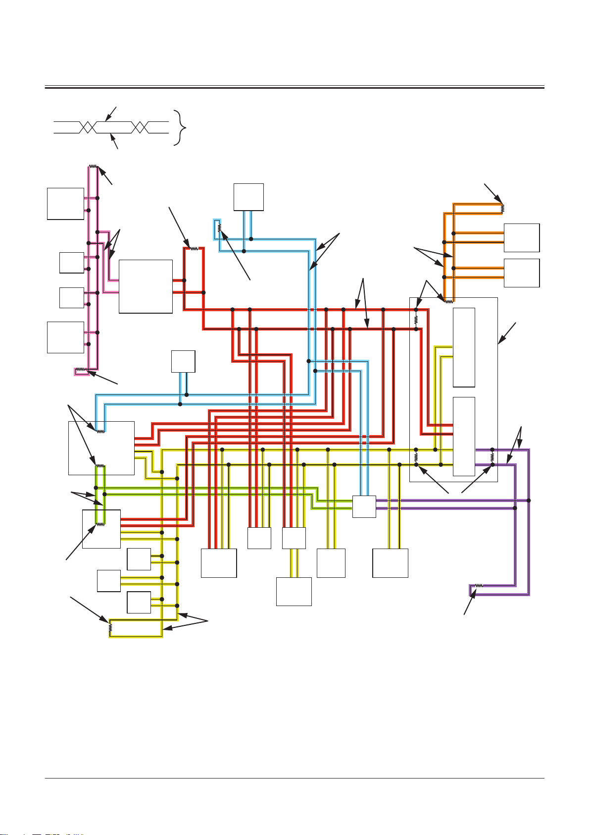
22
23
24
21
7
ECM
8
MC
17
17
Local-CAN
SENSOR-CAN
Power-CAN
18
17
17
20
9
GSM/
GPS
11
MPDr.
IF-CAN
17
17
10
15
16
17
17
32
13
3130
26
6
5
17
17
14
A/C
25
PLCU
1
TCU
12
OPT-CAN
Body-CAN
PL-CAN
17
4
2
3
SECTION 2 SYSTEM
Group 1 Controller
1- TCU
2- CAN-H (High)
3- CAN-L (Low)
4- CAN Bus
5- Panel Switch 1
6- Panel Switch 2
7- ECM (Engine Controller)
8- MC (Main Controller)
9- Communication Controller
10- Monitor Controller
11- MPDr.
12- Aerial Angle Controller
13- Column Display
14- Air Conditioner Controller
15- Monitor Control Unit
16- Information Control Unit
17- Terminal Resistor (120 Ω)
18- Position Sensor
20- Object Detection Sensor
21- DEF Sensor Unit
22- SCR Inlet Exhaust Tempera
ture Sensor, SCR Outlet Ex
haust Temperature Sensor,
DOC Inlet Exhaust Tempera
ture Sensor, DOC Outlet Ex
haust Temperature Sensor
23- Upstream NOx Sensor
24- Downstream NOx Sensor
25- PLCU
26- Rotary Device
30- Option Connector 1
31- Option Connector 2
32- Option Connector 3
TNFQ-02-01-001-1 ja
TONFQ50-EN-00(28/02/2022)
T2-1-2
Page 61

SECTION 2 SYSTEM
Group 2 Control System
Outline of Control System
MC and PLCU are used in order to control the machine operations. The signals from the accelerator pedal sensor, various
sensors, switches, and TCU are sent to MC and PCLU, and processed in the logic circuit.
MC and PCLU send the signal equivalent to the target engine speed to ECM by using CAN communication in order to
control the engine. (Refer to SYSTEM/Engine System.)
In addition, MC and PLCU drive the solenoid valve unit and the torque control solenoid valve in order to control the
pumps and valves.
TCU is used in order to control the machine travel operations. The signals from the shift switch, forward/reverse lever,
various switches, and various sensors of transmission are sent to TCU and processed in the logic circuit.
TCU activates the forward and reverse clutch solenoid valves and speed shift solenoid valve, and controls the
transmission.
Engine Control (ECM)
The engine control consists of the followings.
● Engine Protection Control
● Accelerator Pedal Control
● Auto Warming-Up Control
● Engine Torque Idle Speed-Up Control
● Forward/Reverse Selection Speed Limit Control While Traveling
● Engine Speed Limit Control without Load
● Matching Control While Digging
● Speed Limit Control with Power Mode OFF
● Auto Power Up Speed Control
● Overheat Prevention Speed Limit Control
● Aftertreatment Device Manual Regeneration Control
● Engine Overload Prevention Control
● Engine Max. Speed Limit Control at Stroke End Stall and Front Relief
● Engine Torque Limit Control During Acceleration
TONFQ50-EN-00(28/02/2022)
T2-2-1
Page 62
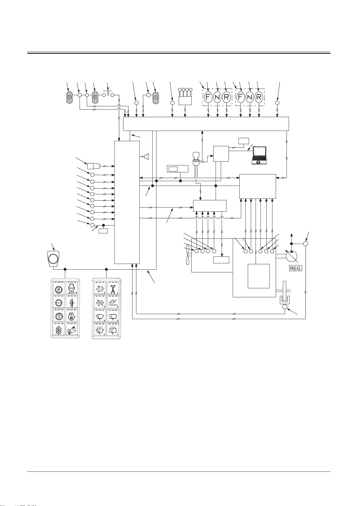
Engine Control System Layout
2
1
83
75
5251 5355 54
32
33 34 35 88
36
33 34 35
48
31
69
71
72
80
73
70
84
86
20
37
43
15
14
74
17
63
3
MC
19
18
60
16
44
7
TCU
9
PLCU
4
5
ECM
13
11
10
64
46
21
38
25
24
23
22
26
27
29
28
30
6
8
41
47
SECTION 2 SYSTEM
Group 2 Control System
1- Accelerator Pedal
2- Accelerator Pedal Sensor
3- MC
4- Monitor Controller
5- ECM
6- Engine
7- TCU
8- Transmission
9- PLCU
10- Main Monitor
11- Column Display
13- Control Lever
14- Rotary Device
15- Panel Switch 1
16- Panel Switch 2
17- Power-CAN
18- Body-CAN
19- PL-CAN
20- SENSOR-CAN
21- IF-CAN
22- Boost Temperature Sensor
23- Crank Speed Sensor
24- Cam Angle Sensor
25- Coolant Temperature Sensor
26- Torque Converter Oil Temper
ature Sensor
27- Torque Converter Input Shaft
Speed Sensor
28- Torque Converter Output
29- Transmission Intermediate
30- Vehicle Speed Sensor
31- Shift Switch
32- Forward/Reverse Lever
33- Forward Position
34- Neutral Position
35- Reverse Position
Shaft Speed Sensor
Shaft Speed Sensor
36- Forward/Reverse Switch
37- Forward/Reverse Selector
Switch
38- Pump Delivery Pressure Sen
sor
41- Parking Brake Pressure Sensor
43- Clutch Cut-o Position Switch
44- Power Mode Switch
46- Sub Monitor
47- Key Switch
48- Hydraulic Oil Temperature
Sensor
51- Brake Pedal (Left)
52- Service Brake Secondary Pres
sure Sensor
53- Brake Pedal (Right)
54- Brake Pedal (Right) Switch
55- Brake Pedal Position Sensor
60- Manual Regeneration Switch
TNFQ-02-02-001-1 ja
63- Aftertreatment Device Regen
eration Signal
64- MPDr.
69- Lift Arm Angle Sensor
70- Bucket Angle Sensor
71- Axle Oil Temperature Sensor
72- Lift Arm Rod Pressure Sensor
73- Lift Arm Bottom Pressure Sen
sor
74- Position Sensor
75- Control Lever Lock Switch
80- Downshift Switch
83- Primary Pilot Pressure Sensor
84- Service Brake Primary Pres
sure Sensor
86- Object Detection Sensor
88- Joystick Steering Selector
Switch
TONFQ50-EN-00(28/02/2022)
T2-2-2
Page 63
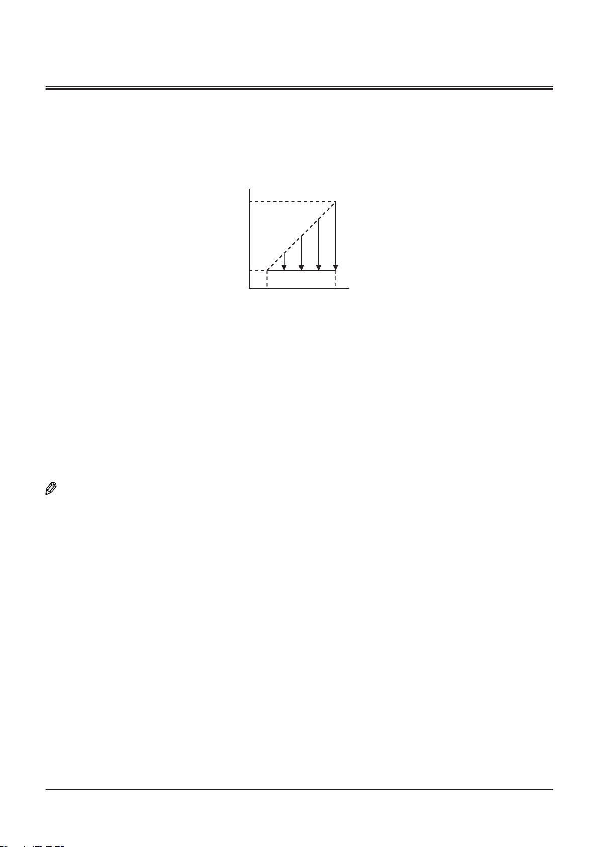
A
E
F
B
DC
SECTION 2 SYSTEM
Group 2 Control System
Engine Protection Control
Purpose:
The engine protection control controls increasing the engine speed and promotes the circulation of the engine oil
immediately after the engine starts. Therefore, the engine (turbocharger) is protected from being damaged.
TNED-02-02-065-1 ja
A- Engine Speed D- Accelerator Pedal Depressing Amount: Fully Depressed
B- Accelerator Pedal Depressing Amount: E- Maximum Rotation Speed
C- Accelerator Pedal Depressing Amount: Not Operated F- Minimum Rotation Speed
Operation:
1. When the engine starts, MC (3) receives the signals from coolant temperature sensor (25), hydraulic oil temperature
sensor (48), and torque converter oil temperature sensor (26). MC (3) sends the signal equivalent to the target engine
speed according to the received signals to ECM (5) by using CAN communication (17).
2. ECM (5) sets the engine speed to minimum rotation speed (F) and holds it for 3 to 40 seconds.
3. When the engine starts and the specied time is passed, MC (3) deactivates the engine protection control.
4. ECM (5) slowly returns the engine speed to the speed according to other engine controls.
NOTE
The priority is given to the engine protection control. Therefore, the engine speed does not change even if the accelerator
pedal is operated when the engine protection control is activated. Other controls are activated after the engine
protection control is deactivated.
TONFQ50-EN-00(28/02/2022)
T2-2-3
Page 64
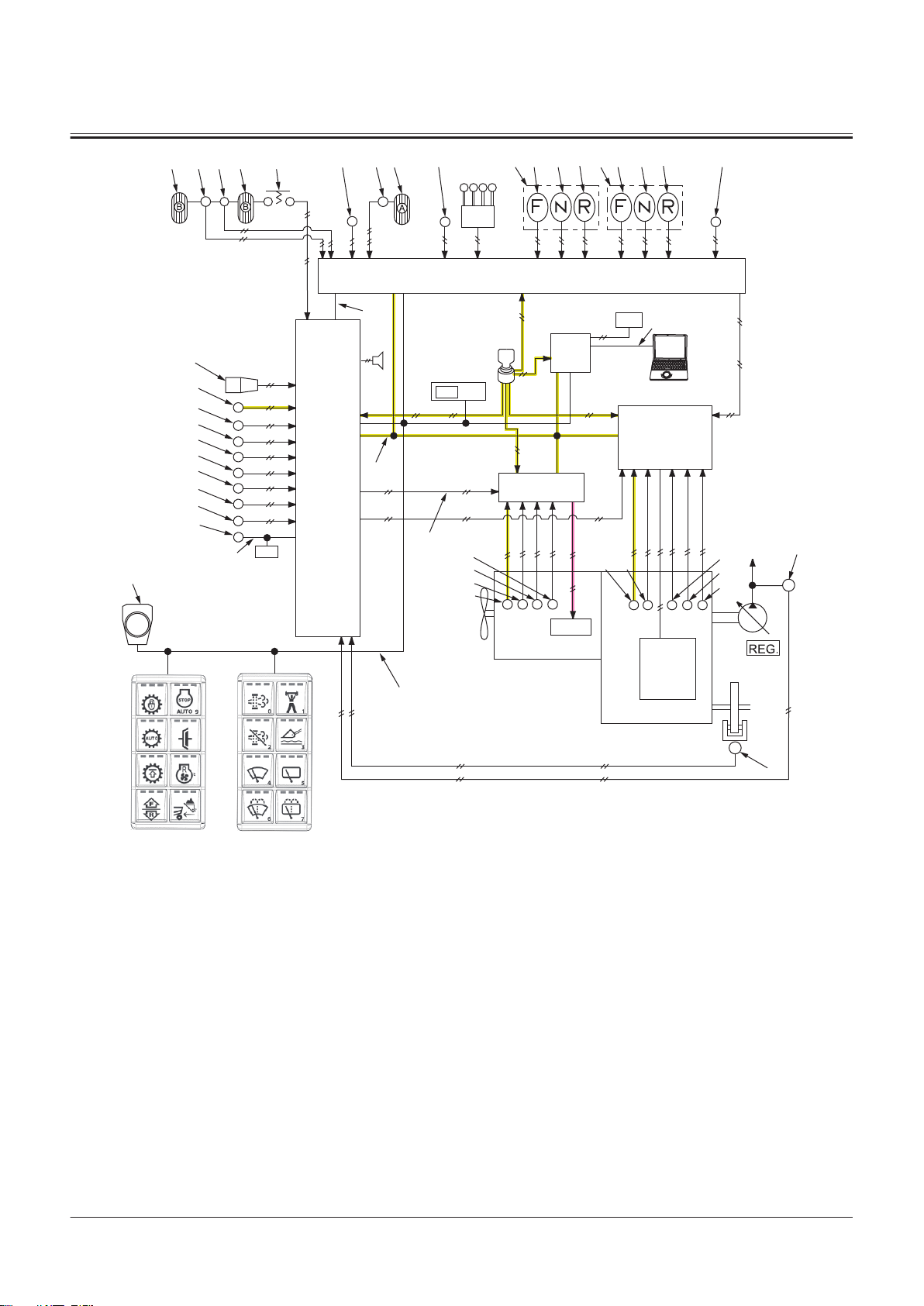
2
1
83
75
5251 5355 54
32
33 34 35 88
36
33 34 35
48
31
69
71
72
80
73
70
84
86
20
37
43
15
14
74
17
63
3
MC
19
18
60
16
44
7
TCU
9
PLCU
4
5
ECM
13
11
10
64
46
21
38
25
24
23
22
26
27
29
28
30
6
8
41
47
SECTION 2 SYSTEM
Group 2 Control System
1- Accelerator Pedal
2- Accelerator Pedal Sensor
3- MC
4- Monitor Controller
5- ECM
6- Engine
7- TCU
8- Transmission
9- PLCU
10- Main Monitor
11- Column Display
13- Control Lever
14- Rotary Device
15- Panel Switch 1
16- Panel Switch 2
17- Power-CAN
18- Body-CAN
19- PL-CAN
20- SENSOR-CAN
21- IF-CAN
22- Boost Temperature Sensor
23- Crank Speed Sensor
24- Cam Angle Sensor
25- Coolant Temperature Sensor
26- Torque Converter Oil Temper
27- Torque Converter Input Shaft
28- Torque Converter Output
29- Transmission Intermediate
30- Vehicle Speed Sensor
31- Shift Switch
32- Forward/Reverse Lever
33- Forward Position
34- Neutral Position
35- Reverse Position
ature Sensor
Speed Sensor
Shaft Speed Sensor
Shaft Speed Sensor
36- Forward/Reverse Switch
37- Forward/Reverse Selector
Switch
38- Pump Delivery Pressure Sen
sor
41- Parking Brake Pressure Sensor
43- Clutch Cut-o Position Switch
44- Power Mode Switch
46- Sub Monitor
47- Key Switch
48- Hydraulic Oil Temperature
Sensor
51- Brake Pedal (Left)
52- Service Brake Secondary Pres
sure Sensor
53- Brake Pedal (Right)
54- Brake Pedal (Right) Switch
55- Brake Pedal Position Sensor
60- Manual Regeneration Switch
TNFQ-02-02-002-1 ja
63- Aftertreatment Device Regen
eration Signal
64- MPDr.
69- Lift Arm Angle Sensor
70- Bucket Angle Sensor
71- Axle Oil Temperature Sensor
72- Lift Arm Rod Pressure Sensor
73- Lift Arm Bottom Pressure Sen
sor
74- Position Sensor
75- Control Lever Lock Switch
80- Downshift Switch
83- Primary Pilot Pressure Sensor
84- Service Brake Primary Pres
sure Sensor
86- Object Detection Sensor
88- Joystick Steering Selector
Switch
TONFQ50-EN-00(28/02/2022)
T2-2-4
Page 65

A
E
F
G
B
DC
SECTION 2 SYSTEM
Group 2 Control System
Accelerator Pedal Control
Purpose:
The accelerator pedal control controls the engine speed according to the depressing amount of accelerator pedal (1).
TNED-02-02-002-1 ja
A- Engine Speed E- Maximum Rotation Speed
B- Accelerator Pedal Depressing Amount
C- Accelerator Pedal Depressing Amount: Not Operated G- Minimum Rotation Speed
D- Accelerator Pedal Depressing Amount: Fully Depressed
F- Specied Value (1100 min-1)
Operation:
1. PLCU (9) receives the signals (the demand engine speed) from accelerator pedal sensor (2) and sends them to MC (3)
by using CAN communication (17). MC (3) sends the signal equivalent to the target engine speed according to the
received signals to ECM (5) by using CAN communication (17).
2. ECM (5) controls the engine speed according to CAN communication (17).
3. When accelerator pedal sensor (2) becomes abnormal, MC (3) sends the backup signals to ECM (5).
4. ECM (5) limits the engine speed to specied value (F). (Backup Control).
Deactivation of Backup Control:
1. When accelerator pedal sensor (2) becomes normal, MC (3) deactivates the backup control by the following
procedure.
• Turn OFF key switch (47)
• Wait more than 10 second.
• Turn ON key switch (47)
2. Therefore, ECM (5) returns the engine speed according to the accelerator pedal control.
TONFQ50-EN-00(28/02/2022)
T2-2-5
Page 66

2
1
83
75
5251 5355 54
32
33 34 35 88
36
33 34 35
48
31
69
71
72
80
73
70
84
86
20
37
43
15
14
74
17
63
3
MC
19
18
60
16
44
7
TCU
9
PLCU
4
5
ECM
13
11
10
64
46
21
38
25
24
23
22
26
27
29
28
30
6
8
41
47
SECTION 2 SYSTEM
Group 2 Control System
1- Accelerator Pedal
2- Accelerator Pedal Sensor
3- MC
4- Monitor Controller
5- ECM
6- Engine
7- TCU
8- Transmission
9- PLCU
10- Main Monitor
11- Column Display
13- Control Lever
14- Rotary Device
15- Panel Switch 1
16- Panel Switch 2
17- Power-CAN
18- Body-CAN
19- PL-CAN
20- SENSOR-CAN
21- IF-CAN
22- Boost Temperature Sensor
23- Crank Speed Sensor
24- Cam Angle Sensor
25- Coolant Temperature Sensor
26- Torque Converter Oil Temper
27- Torque Converter Input Shaft
28- Torque Converter Output
29- Transmission Intermediate
30- Vehicle Speed Sensor
31- Shift Switch
32- Forward/Reverse Lever
33- Forward Position
34- Neutral Position
35- Reverse Position
ature Sensor
Speed Sensor
Shaft Speed Sensor
Shaft Speed Sensor
36- Forward/Reverse Switch
37- Forward/Reverse Selector
Switch
38- Pump Delivery Pressure Sen
sor
41- Parking Brake Pressure Sensor
43- Clutch Cut-o Position Switch
44- Power Mode Switch
46- Sub Monitor
47- Key Switch
48- Hydraulic Oil Temperature
Sensor
51- Brake Pedal (Left)
52- Service Brake Secondary Pres
sure Sensor
53- Brake Pedal (Right)
54- Brake Pedal (Right) Switch
55- Brake Pedal Position Sensor
60- Manual Regeneration Switch
TNFQ-02-02-003-1 ja
63- Aftertreatment Device Regen
eration Signal
64- MPDr.
69- Lift Arm Angle Sensor
70- Bucket Angle Sensor
71- Axle Oil Temperature Sensor
72- Lift Arm Rod Pressure Sensor
73- Lift Arm Bottom Pressure Sen
sor
74- Position Sensor
75- Control Lever Lock Switch
80- Downshift Switch
83- Primary Pilot Pressure Sensor
84- Service Brake Primary Pres
sure Sensor
86- Object Detection Sensor
88- Joystick Steering Selector
Switch
TONFQ50-EN-00(28/02/2022)
T2-2-6
Page 67
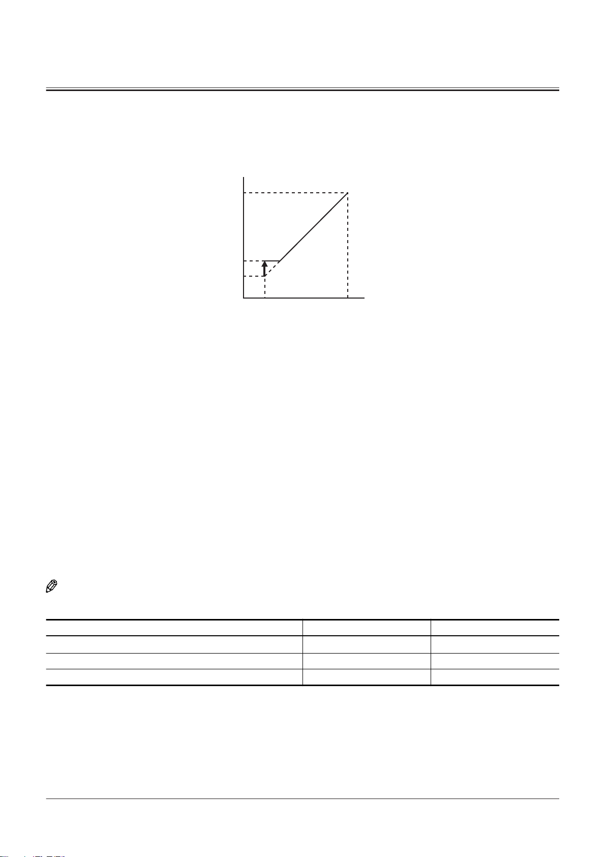
A
C
D
E
B
SECTION 2 SYSTEM
Group 2 Control System
Auto Warming-Up Control
Purpose:
The auto warming-up control automatically warms up the engine.
A- Engine Speed D- Auto Warming-Up Speed
B- Target Engine Speed E- Minimum Rotation Speed
C- Maximum Rotation Speed
TNED-02-02-004-1 ja
Operation:
1. MC (3) receives the signal from hydraulic oil temperature sensor (48) and coolant temperature sensor (25).
2. When any of the following conditions exists, MC (3) sends the signals equivalent to the target engine speed to ECM (5)
by using CAN communication (17).
• When key switch (47) is in the ON position and hydraulic oil temperature is 0 °C or lower
• When key switch (47) is in the START position and hydraulic oil temperature is 0 °C or lower
3. ECM (5) increases the engine speed to auto warming-up speed (D).
4. When any of the following conditions exist, MC (3) deactivates the auto warming-up control.
• When 30 minutes passed after setting key switch (47) to START position
• Hydraulic oil temperature: 30 °C or more
• Coolant Temperature: 40 °C or more
• Parking Brake: UNLOCK
5. Therefore, ECM (5) returns the engine speed according to the accelerator pedal control.
NOTE
"Normal" or "Ultra Low Temperature" can be set as follows by using MPDr. (64).
Normal Ultra Low Temperature
Auto Warming-Up Speed
Hydraulic Oil Temperature Non-activation 30 °C 40 °C
Coolant Temperature Non-activation 40 °C 50 °C
1000 (min-1) 1100 (min-1)
IMPORTANT
When adjusting the auto-idle speed, deactivate the auto warming-up control by using sub monitor (46). Or wait
the adjustment until 30 minutes after the engine starts.
TONFQ50-EN-00(28/02/2022)
T2-2-7
Page 68

2
1
83
75
5251 5355 54
32
33 34 35 88
36
33 34 35
48
31
69
71
72
80
73
70
84
86
20
37
43
15
14
74
17
63
3
MC
19
18
60
16
44
7
TCU
9
PLCU
4
5
ECM
13
11
10
64
46
21
38
25
24
23
22
26
27
29
28
30
6
8
41
47
SECTION 2 SYSTEM
Group 2 Control System
1- Accelerator Pedal
2- Accelerator Pedal Sensor
3- MC
4- Monitor Controller
5- ECM
6- Engine
7- TCU
8- Transmission
9- PLCU
10- Main Monitor
11- Column Display
13- Control Lever
14- Rotary Device
15- Panel Switch 1
16- Panel Switch 2
17- Power-CAN
18- Body-CAN
19- PL-CAN
20- SENSOR-CAN
21- IF-CAN
22- Boost Temperature Sensor
23- Crank Speed Sensor
24- Cam Angle Sensor
25- Coolant Temperature Sensor
26- Torque Converter Oil Temper
27- Torque Converter Input Shaft
28- Torque Converter Output
29- Transmission Intermediate
30- Vehicle Speed Sensor
31- Shift Switch
32- Forward/Reverse Lever
33- Forward Position
34- Neutral Position
35- Reverse Position
ature Sensor
Speed Sensor
Shaft Speed Sensor
Shaft Speed Sensor
36- Forward/Reverse Switch
37- Forward/Reverse Selector
Switch
38- Pump Delivery Pressure Sen
sor
41- Parking Brake Pressure Sensor
43- Clutch Cut-o Position Switch
44- Power Mode Switch
46- Sub Monitor
47- Key Switch
48- Hydraulic Oil Temperature
Sensor
51- Brake Pedal (Left)
52- Service Brake Secondary Pres
sure Sensor
53- Brake Pedal (Right)
54- Brake Pedal (Right) Switch
55- Brake Pedal Position Sensor
60- Manual Regeneration Switch
TNFQ-02-02-004-1 ja
63- Aftertreatment Device Regen
eration Signal
64- MPDr.
69- Lift Arm Angle Sensor
70- Bucket Angle Sensor
71- Axle Oil Temperature Sensor
72- Lift Arm Rod Pressure Sensor
73- Lift Arm Bottom Pressure Sen
sor
74- Position Sensor
75- Control Lever Lock Switch
80- Downshift Switch
83- Primary Pilot Pressure Sensor
84- Service Brake Primary Pres
sure Sensor
86- Object Detection Sensor
88- Joystick Steering Selector
Switch
TONFQ50-EN-00(28/02/2022)
T2-2-8
Page 69
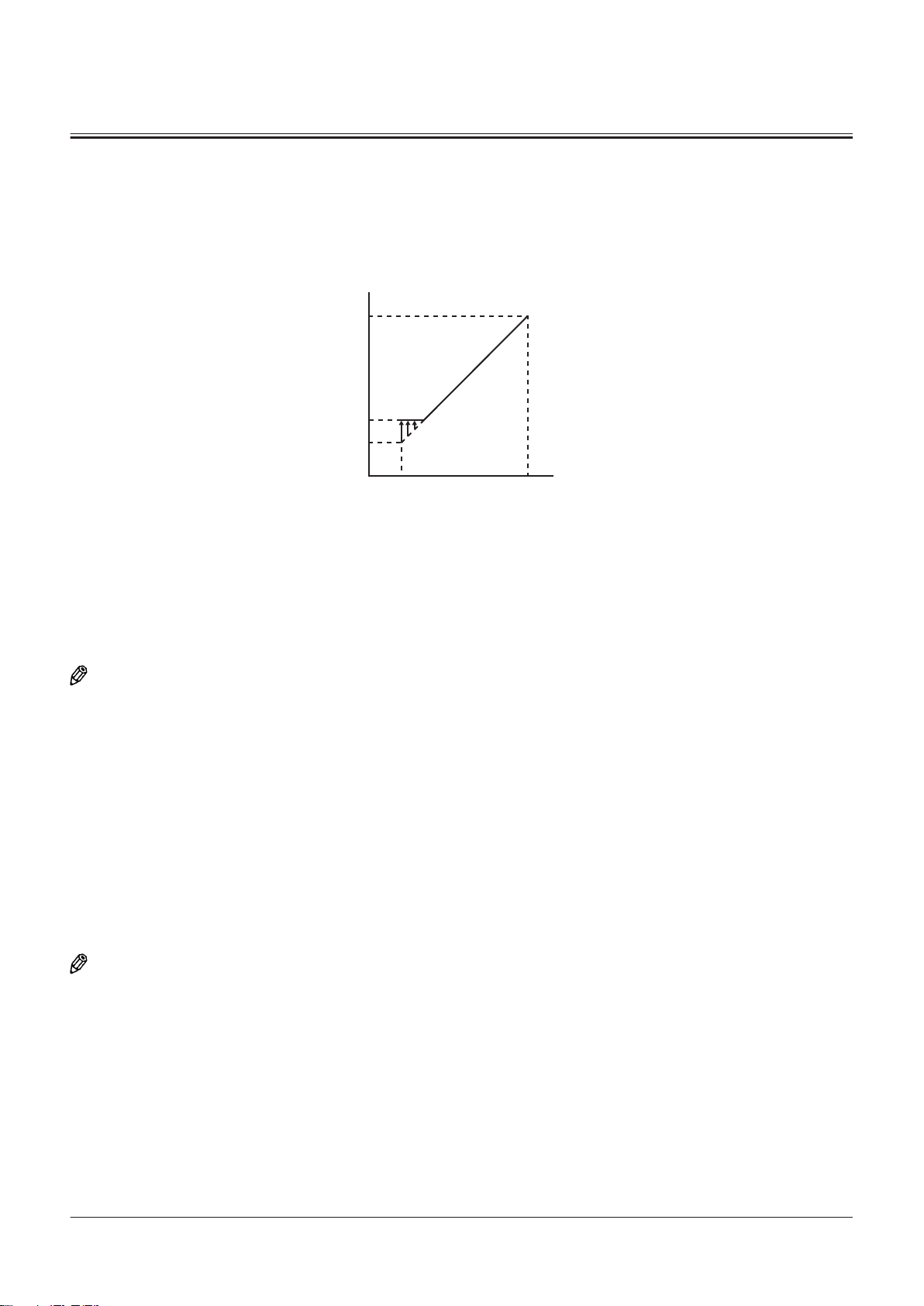
A
E
F
G
B
DC
SECTION 2 SYSTEM
Group 2 Control System
Engine Torque Idle Speed-Up Control
Purpose:
In case the engine speed is slow and the engine load is large, the engine torque idle speed-up control increases the
engine speed in order to prevent the engine stall.
TNED-02-02-006-1 ja
A- Engine Speed E- Maximum Rotation Speed
B- Accelerator Pedal Depressing Amount
F- Engine Torque Idle Speed-Up Speed (Max. 1150 min-1)
C- Accelerator Pedal Depressing Amount: Not Operated G- Minimum Rotation Speed
D- Accelerator Pedal Depressing Amount: Fully Depressed
Operation:
NOTE
The time when forward/reverse switch (36) is eective is explained as an example.
1. PLCU (9) receives the signals from accelerator pedal sensor (2), forward/reverse lever (32) or forward/reverse switch
(36), and sends them to TCU (7) by using CAN communication (17). TCU (7) sends the signals to MC (3) by using CAN
communication (17).
2. When all following conditions exist, MC (3) sends the signal equivalent to the target engine speed to ECM (5) by using
CAN communication (17).
• Forward/Reverse Lever (32) or Forward/Reverse Switch (36): Forward Position (33) or Reverse Position (35)
• Vehicle Speed: less than 20 km/h
• Accelerator Pedal (1) Depressing Amount: Lightly (Engine Speed: less than 1150 min-1)
• Engine Torque: over specied value (Reference: over 20 %)
3. ECM (5) increases the engine speed to engine torque idle speed-up speed (F).
NOTE
Forward/reverse switch (36) is also equipped on machines mounted with the joystick steering system. Forward/reverse
switch (36) on the joystick steering system side is shifted between operable and inoperable by the joystick steering
selector switch (88).
TONFQ50-EN-00(28/02/2022)
T2-2-9
Page 70
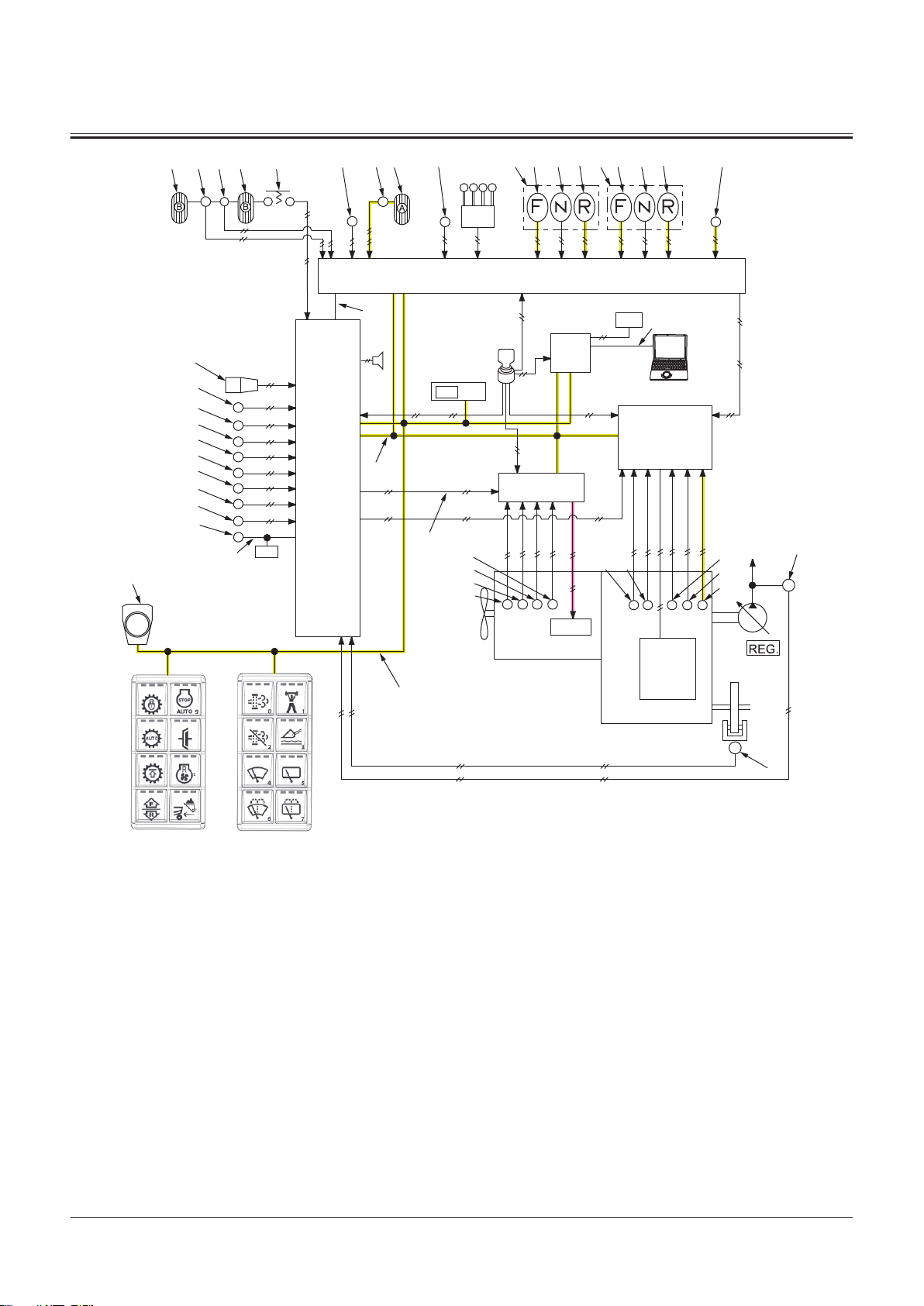
2
1
83
75
5251 5355 54
32
33 34 35 88
36
33 34 35
48
31
69
71
72
80
73
70
84
86
20
37
43
15
14
74
17
63
3
MC
19
18
60
16
44
7
TCU
9
PLCU
4
5
ECM
13
11
10
64
46
21
38
25
24
23
22
26
27
29
28
30
6
8
41
47
SECTION 2 SYSTEM
Group 2 Control System
1- Accelerator Pedal
2- Accelerator Pedal Sensor
3- MC
4- Monitor Controller
5- ECM
6- Engine
7- TCU
8- Transmission
9- PLCU
10- Main Monitor
11- Column Display
13- Control Lever
14- Rotary Device
15- Panel Switch 1
16- Panel Switch 2
17- Power-CAN
18- Body-CAN
19- PL-CAN
20- SENSOR-CAN
21- IF-CAN
22- Boost Temperature Sensor
23- Crank Speed Sensor
24- Cam Angle Sensor
25- Coolant Temperature Sensor
26- Torque Converter Oil Temper
27- Torque Converter Input Shaft
28- Torque Converter Output
29- Transmission Intermediate
30- Vehicle Speed Sensor
31- Shift Switch
32- Forward/Reverse Lever
33- Forward Position
34- Neutral Position
35- Reverse Position
ature Sensor
Speed Sensor
Shaft Speed Sensor
Shaft Speed Sensor
36- Forward/Reverse Switch
37- Forward/Reverse Selector
Switch
38- Pump Delivery Pressure Sen
sor
41- Parking Brake Pressure Sensor
43- Clutch Cut-o Position Switch
44- Power Mode Switch
46- Sub Monitor
47- Key Switch
48- Hydraulic Oil Temperature
Sensor
51- Brake Pedal (Left)
52- Service Brake Secondary Pres
sure Sensor
53- Brake Pedal (Right)
54- Brake Pedal (Right) Switch
55- Brake Pedal Position Sensor
60- Manual Regeneration Switch
TNFQ-02-02-005-1 ja
63- Aftertreatment Device Regen
eration Signal
64- MPDr.
69- Lift Arm Angle Sensor
70- Bucket Angle Sensor
71- Axle Oil Temperature Sensor
72- Lift Arm Rod Pressure Sensor
73- Lift Arm Bottom Pressure Sen
sor
74- Position Sensor
75- Control Lever Lock Switch
80- Downshift Switch
83- Primary Pilot Pressure Sensor
84- Service Brake Primary Pres
sure Sensor
86- Object Detection Sensor
88- Joystick Steering Selector
Switch
TONFQ50-EN-00(28/02/2022)
T2-2-10
Page 71
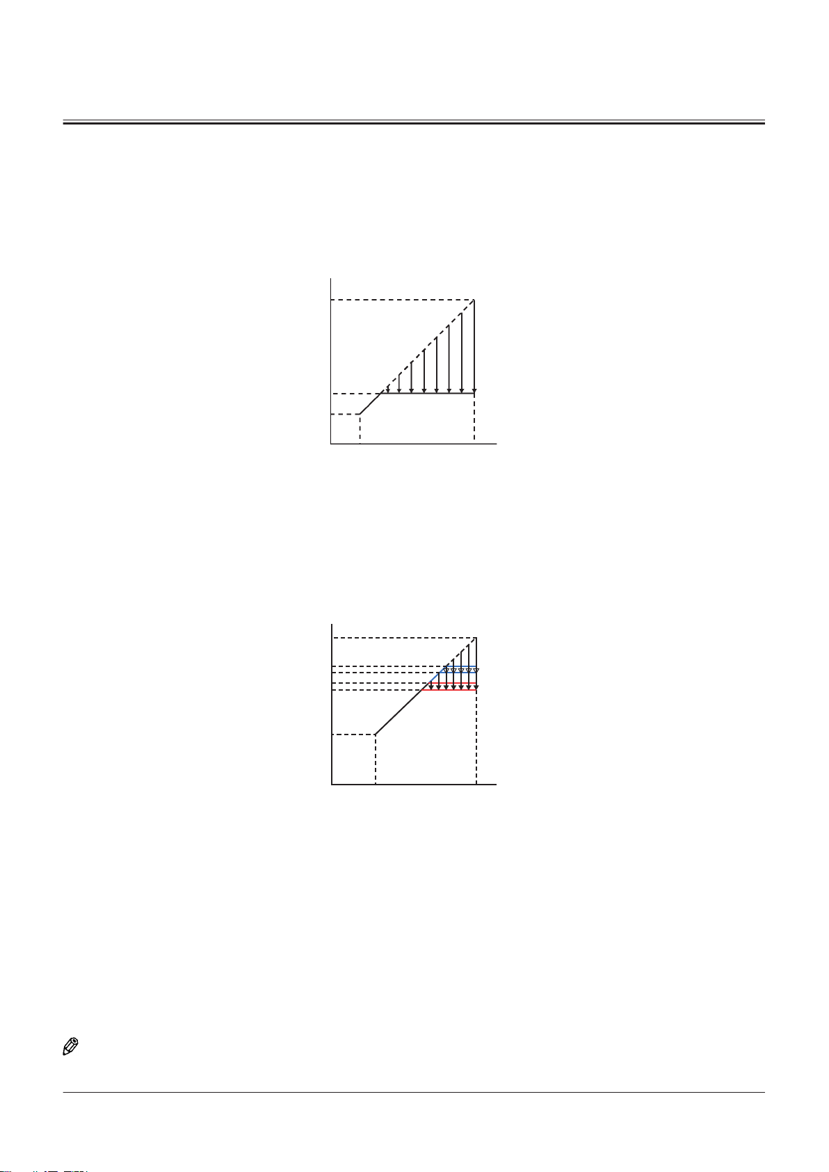
A
B
D
C
G
F
E
A
B
D
C
G
E
H
J
L
M
SECTION 2 SYSTEM
Group 2 Control System
Forward/Reverse Selection Speed Limit Control While Traveling
Purpose:
The forward/reverse selection speed limit control while traveling limits the engine speed when shifting the travel
direction. Shock and drift amount of the vehicle are reduced when shifting the travel direction by slowdown function of
the engine brake.
Mode 1
TNED-02-02-009-1 ja
A- Engine Speed E- Maximum Rotation Speed
B- Accelerator Pedal Depressing Amount
F- Specied Value (1300 min-1)
C- Accelerator Pedal Depressing Amount: Not Operated G- Minimum Rotation Speed
D- Accelerator Pedal Depressing Amount: Fully Depressed
Mode 2
TNUD-02-02-007-1 ja
A- Engine Speed G- Minimum Rotation Speed
B- Accelerator Pedal Depressing Amount H- Specied Value (Other Than Command 1st Speed) (1750
min-1)
C- Accelerator Pedal Depressing Amount: Not Operated J- Specied Value (Other Than Command 1st Speed) (1650
min-1)
D- Accelerator Pedal Depressing Amount: Fully Depressed
E- Maximum Rotation Speed
Operation:
NOTE
The time when forward/reverse switch (36) is eective is explained as an example.
L- Specied Value (Command 1st Speed) (1750 min-1)
M- Specied Value (Command 1st Speed) (1650 min-1)
TONFQ50-EN-00(28/02/2022)
T2-2-11
Page 72

SECTION 2 SYSTEM
Group 2 Control System
1. PLCU (9) receives the signals from forward/reverse lever (32) and forward/reverse switch (36), and sends the FNR
command signal to TCU (7) and MC (3) by using CAN communication (17).
2. MC (3) sends the speed shift signal from shift switch (31) to TCU (7). TCU (7) sends the vehicle speed signal,
transmission speed shift signal, and current FNR command signal to MC (3) by using CAN communication (17).
3. When all following conditions exist, MC (3) sends the signal equivalent to the target engine speed to ECM (5) by using
CAN communication (17).
• Forward/Reverse Lever (32) or Forward/Reverse Switch (36): Forward Position (33) or Reverse Position (35)
• Vehicle Speed: over 3.5 km/h
4. ECM (5) reduces and limits the engine speed to specied values (mode 1 or mode 2) according to the CAN signal.
Mode 1: When the current FNR command signal of TCU (7) and the FNR command signal of MC (3) do not match, the
engine speed is controlled to specied value (F).
Mode 2: When the current FNR command signal of TCU (7) and the FNR command signal of MC (3) match, the engine
speed is controlled to specied value (H) or (L), and then further to specied value (J) or (M).
Deactivation:
NOTE
The time when forward/reverse switch (36) is eective is explained as an example.
1. When of the any following conditions exists, ECM (5) returns the engine speed according to the accelerator pedal
control.
• Vehicle Speed: less than 3.5 km/h
• Forward/Reverse Lever (32) and Forward/Reverse Switch (36): Neutral Position (34)
NOTE
Forward/reverse switch (36) is also equipped on machines mounted with the joystick steering system. Forward/reverse
switch (36) on the joystick steering system side is shifted between operable and inoperable by the joystick steering
selector switch (88).
TONFQ50-EN-00(28/02/2022)
T2-2-12
Page 73

2
1
83
75
5251 5355 54
32
33 34 35 88
36
33 34 35
48
31
69
71
72
80
73
70
84
86
20
37
43
15
14
74
17
63
3
MC
19
18
60
16
44
7
TCU
9
PLCU
4
5
ECM
13
11
10
64
46
21
38
25
24
23
22
26
27
29
28
30
6
8
41
47
SECTION 2 SYSTEM
Group 2 Control System
1- Accelerator Pedal
2- Accelerator Pedal Sensor
3- MC
4- Monitor Controller
5- ECM
6- Engine
7- TCU
8- Transmission
9- PLCU
10- Main Monitor
11- Column Display
13- Control Lever
14- Rotary Device
15- Panel Switch 1
16- Panel Switch 2
17- Power-CAN
18- Body-CAN
19- PL-CAN
20- SENSOR-CAN
21- IF-CAN
22- Boost Temperature Sensor
23- Crank Speed Sensor
24- Cam Angle Sensor
25- Coolant Temperature Sensor
26- Torque Converter Oil Temper
27- Torque Converter Input Shaft
28- Torque Converter Output
29- Transmission Intermediate
30- Vehicle Speed Sensor
31- Shift Switch
32- Forward/Reverse Lever
33- Forward Position
34- Neutral Position
35- Reverse Position
ature Sensor
Speed Sensor
Shaft Speed Sensor
Shaft Speed Sensor
36- Forward/Reverse Switch
37- Forward/Reverse Selector
Switch
38- Pump Delivery Pressure Sen
sor
41- Parking Brake Pressure Sensor
43- Clutch Cut-o Position Switch
44- Power Mode Switch
46- Sub Monitor
47- Key Switch
48- Hydraulic Oil Temperature
Sensor
51- Brake Pedal (Left)
52- Service Brake Secondary Pres
sure Sensor
53- Brake Pedal (Right)
54- Brake Pedal (Right) Switch
55- Brake Pedal Position Sensor
60- Manual Regeneration Switch
TNFQ-02-02-008-1 ja
63- Aftertreatment Device Regen
eration Signal
64- MPDr.
69- Lift Arm Angle Sensor
70- Bucket Angle Sensor
71- Axle Oil Temperature Sensor
72- Lift Arm Rod Pressure Sensor
73- Lift Arm Bottom Pressure Sen
sor
74- Position Sensor
75- Control Lever Lock Switch
80- Downshift Switch
83- Primary Pilot Pressure Sensor
84- Service Brake Primary Pres
sure Sensor
86- Object Detection Sensor
88- Joystick Steering Selector
Switch
TONFQ50-EN-00(28/02/2022)
T2-2-13
Page 74
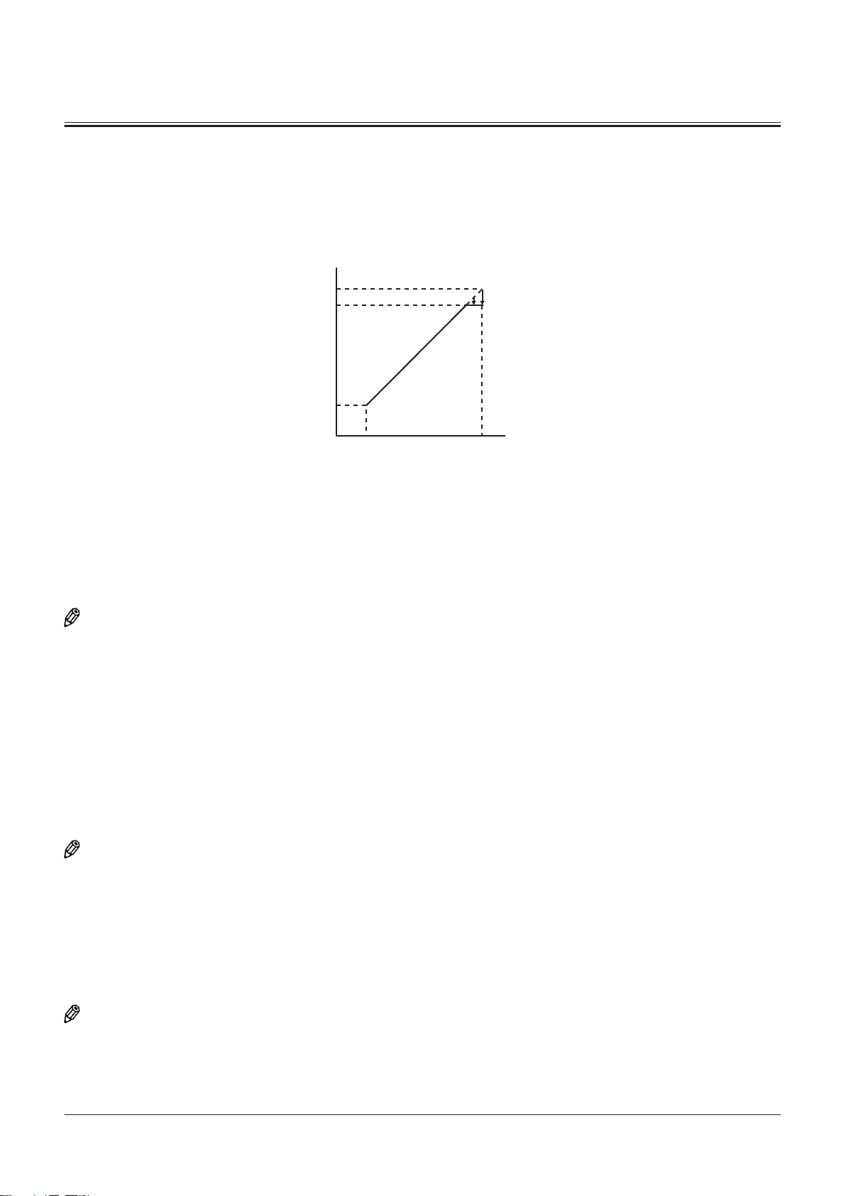
A
E
F
G
H
B
C
SECTION 2 SYSTEM
Group 2 Control System
Engine Speed Limit Control without Load
Purpose:
The engine speed limit control without load limits the maximum engine speed of the engine when the pump delivery
pressure is less than specied value. Therefore, fuel consumption is reduced.
TNUD-02-02-009-1 ja
A- Engine Speed
B- Accelerator Pedal Depressing Amount G- Minimum Rotation Speed
C- Accelerator Pedal Depressing Amount: Not Operated H- Accelerator Pedal Depressing Amount: Fully Depressed
E- Maximum Rotation Speed
Operation:
F- Specied Value (2080 min-1)
NOTE
The time when forward/reverse switch (36) is eective is explained as an example.
1. MC (3) receives the signal from the pump delivery pressure sensor (38).
2. When all following conditions exist, MC (3) sends the signal equivalent to the target engine speed to ECM (5) by using
CAN communication (17).
• Pump Delivery Pressure: less than specied value (Reference: Less than 11 MPa)
• Forward/Reverse Lever (32) and Forward/Reverse Switch (36): Neutral Position (34)
• Vehicle Speed: less than 2 km/h
3. ECM (5) sets the engine speed to specied value (F) according to CAN communication (17).
Deactivation:
NOTE
The time when forward/reverse switch (36) is eective is explained as an example.
1. When any of the following conditions exists, ECM (5) returns the engine speed according to the accelerator pedal
control.
• Pump Delivery Pressure: High Pressure (Reference: 11 MPa or more)
• Forward/Reverse Lever (32) or Forward/Reverse Switch (36): Forward Position (33) or Reverse Position (35)
• Vehicle Speed: 2 km/h or more
NOTE
In case performing the lift arm raise/lower operation with the bucket empty, pump delivery pressure becomes medium
pressure (3 to 14 MPa).
TONFQ50-EN-00(28/02/2022)
T2-2-14
Page 75
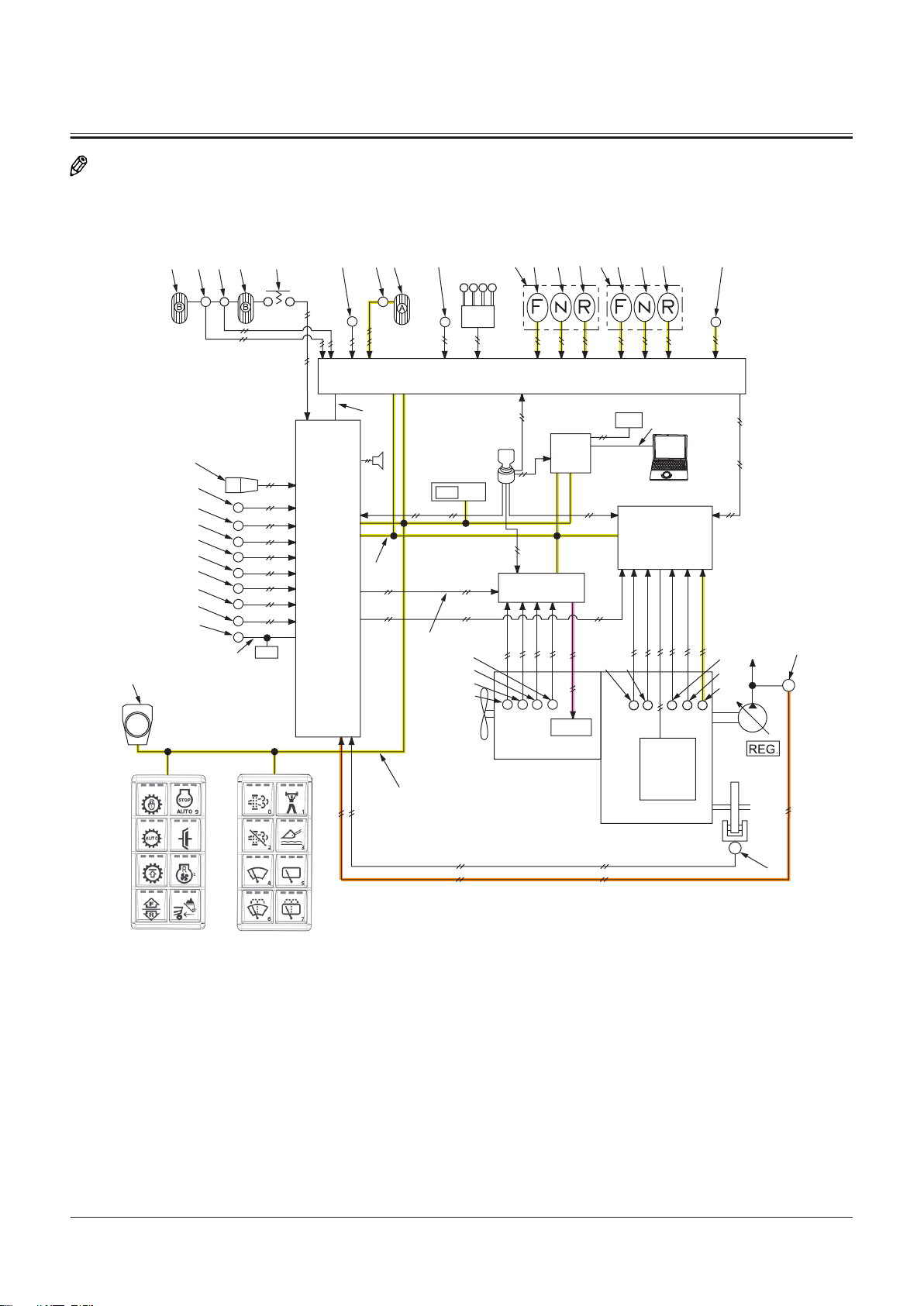
2
1
83
75
5251 5355 54
32
33 34 35 88
36
33 34 35
48
31
69
71
72
80
73
70
84
86
20
37
43
15
14
74
17
63
3
MC
19
18
60
16
44
7
TCU
9
PLCU
4
5
ECM
13
11
10
64
46
21
38
25
24
23
22
26
27
29
28
30
6
8
41
47
SECTION 2 SYSTEM
Group 2 Control System
NOTE
Forward/reverse switch (36) is also equipped on machines mounted with the joystick steering system. Forward/reverse
switch (36) on the joystick steering system side is shifted between operable and inoperable by the joystick steering
selector switch (88).
TNFQ-02-02-010-1 ja
TONFQ50-EN-00(28/02/2022)
T2-2-15
Page 76
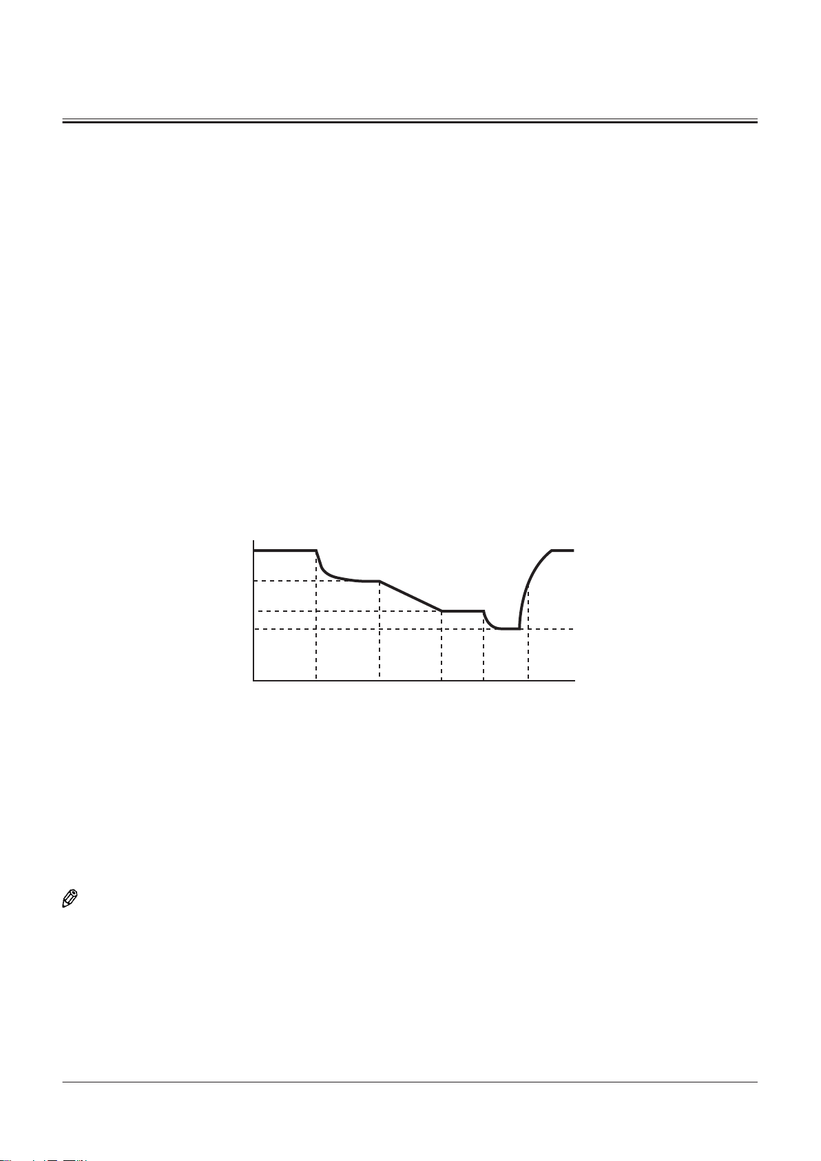
A
B
E F G HD
J
K
L
M
SECTION 2 SYSTEM
Group 2 Control System
1- Accelerator Pedal
2- Accelerator Pedal Sensor
3- MC
4- Monitor Controller
5- ECM
6- Engine
7- TCU
8- Transmission
9- PLCU
10- Main Monitor
11- Column Display
13- Control Lever
14- Rotary Device
15- Panel Switch 1
16- Panel Switch 2
17- Power-CAN
18- Body-CAN
19- PL-CAN
20- SENSOR-CAN
21- IF-CAN
22- Boost Temperature Sensor
23- Crank Speed Sensor
24- Cam Angle Sensor
25- Coolant Temperature Sensor
26- Torque Converter Oil Temper
ature Sensor
27- Torque Converter Input Shaft
Speed Sensor
28- Torque Converter Output
Shaft Speed Sensor
29- Transmission Intermediate
Shaft Speed Sensor
30- Vehicle Speed Sensor
31- Shift Switch
32- Forward/Reverse Lever
33- Forward Position
34- Neutral Position
35- Reverse Position
36- Forward/Reverse Switch
37- Forward/Reverse Selector
Switch
38- Pump Delivery Pressure Sen
sor
41- Parking Brake Pressure Sensor
43- Clutch Cut-o Position Switch
44- Power Mode Switch
46- Sub Monitor
47- Key Switch
48- Hydraulic Oil Temperature
Sensor
51- Brake Pedal (Left)
52- Service Brake Secondary Pres
sure Sensor
53- Brake Pedal (Right)
54- Brake Pedal (Right) Switch
55- Brake Pedal Position Sensor
60- Manual Regeneration Switch
63- Aftertreatment Device Regen
eration Signal
64- MPDr.
69- Lift Arm Angle Sensor
70- Bucket Angle Sensor
71- Axle Oil Temperature Sensor
72- Lift Arm Rod Pressure Sensor
73- Lift Arm Bottom Pressure Sen
sor
74- Position Sensor
75- Control Lever Lock Switch
80- Downshift Switch
83- Primary Pilot Pressure Sensor
84- Service Brake Primary Pres
sure Sensor
86- Object Detection Sensor
88- Joystick Steering Selector
Switch
Matching Control While Digging
Purpose:
The matching control while digging reduces the driving force by limiting the maximum engine speed of the engine and
improves the balance between driving force and digging force.
TNUD-02-02-011-1 ja
A- Engine Speed Limit Value H- At End of Digging
B- Operating Time (Second) J- Maximum Engine Speed
D- At Start of Digging H- Specied Value (While Digging)
E- While Digging L- Specied Value (While Fully Digging)
F- While Fully Digging M- Specied Value (While Scraping Up)
G- While Scooping Up
Operation:
NOTE
The time when forward/reverse switch (36) is eective is explained as an example.
1. TCU (7) sends the speed shift signals of transmission (8) to MC (3) by using CAN communication (17).
2. ECM (5) receives the signals from cam angle sensor (24) and crank speed sensor (23).
3. ECM (5) calculates them and sends a signal corresponding to the actual engine speed to MC (3) by using CAN
communication (17).
4. MC (3) receives the signals from the pump delivery pressure sensor (38) and power mode switch (44).
TONFQ50-EN-00(28/02/2022)
T2-2-16
Page 77
SECTION 2 SYSTEM
Group 2 Control System
5. When all following conditions exist, MC (3) sends the signal equivalent to the target engine speed to ECM (5) by using
CAN communication (17).
• Forward/Reverse Lever (32) or Forward/Reverse Switch (36): Forward Position (33)
• Pump Delivery Pressure: High Pressure (Reference: 13 MPa or more)
• Torque Converter Speed Ratio: less than specied value (Reference: 15% or less)
NOTE
The torque converter speed ratio is calculated from the following equation.
N=P/Q
N- Torque Converter Speed Ratio
P- Torque Converter Output Shaft Speed
Q- Actual engine speed
6. ECM (5) sets the engine speed to specied value (K), specied value (L), and specied value (M) according to CAN
communication (17).
Engine Speed according to Work Mode (Reference, at 1st Speed)
Digging Control Mode
Power Mode 2000 1840 1800
Standard 1750 1730 1800
Fork 2230 2230 2230
Digging (Heavy) 2000 1840 1800
Digging (Light) 1750 1730 1800
Digging (K) (Unit: min-1)
Fully Digging (L) (Unit:
min-1)
Scooping Up (M) (Unit: min-1)
NOTE
The engine speed diers according to the power mode and digging control mode settings.
NOTE
Forward/reverse switch (36) is also equipped on machines mounted with the joystick steering system. Forward/reverse
switch (36) on the joystick steering system side is shifted between operable and inoperable by the joystick steering
selector switch (88).
TONFQ50-EN-00(28/02/2022)
T2-2-17
Page 78
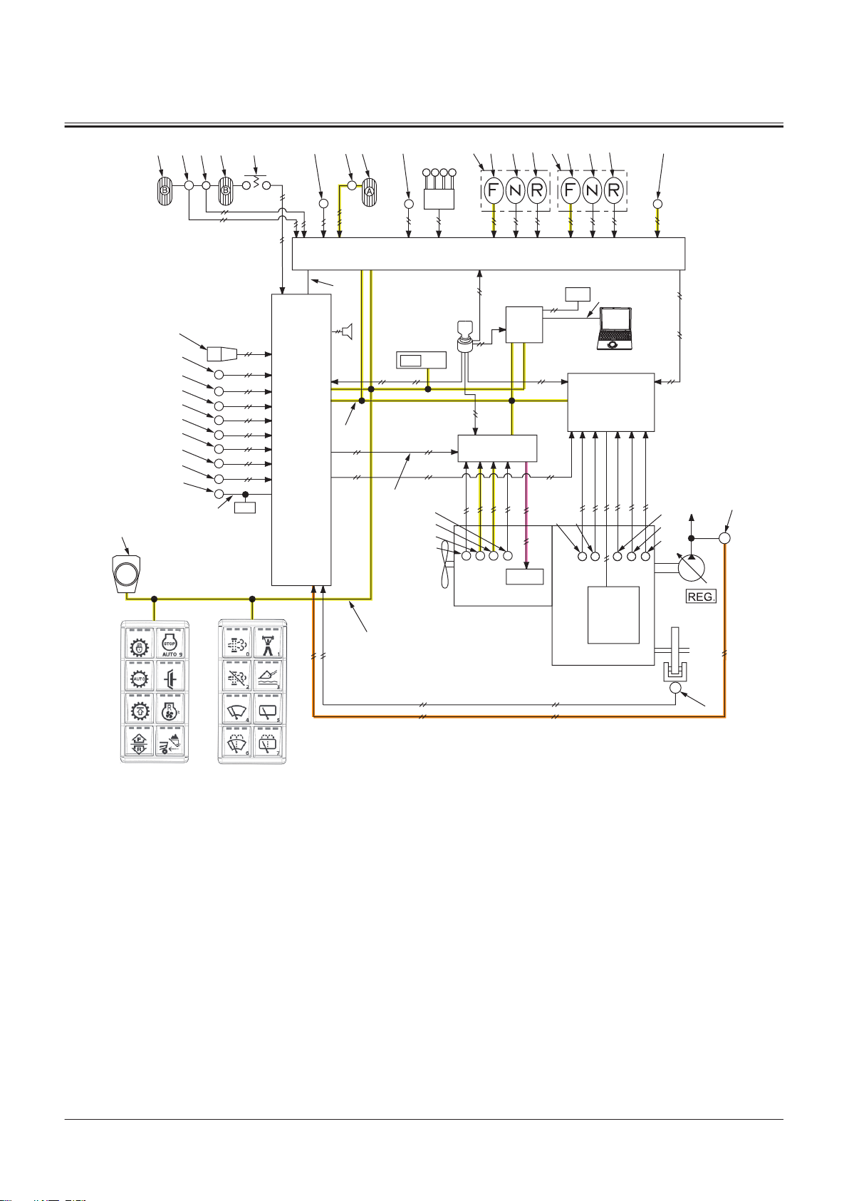
2
1
83
75
5251 5355 54
32
33 34 35 88
36
33 34 35
48
31
69
71
72
80
73
70
84
86
20
37
43
15
14
74
17
63
3
MC
19
18
60
16
44
7
TCU
9
PLCU
4
5
ECM
13
11
10
64
46
21
38
25
24
23
22
26
27
29
28
30
6
8
41
47
SECTION 2 SYSTEM
Group 2 Control System
1- Accelerator Pedal
2- Accelerator Pedal Sensor
3- MC
4- Monitor Controller
5- ECM
6- Engine
7- TCU
8- Transmission
9- PLCU
10- Main Monitor
11- Column Display
13- Control Lever
14- Rotary Device
15- Panel Switch 1
16- Panel Switch 2
17- Power-CAN
18- Body-CAN
19- PL-CAN
20- SENSOR-CAN
21- IF-CAN
22- Boost Temperature Sensor
23- Crank Speed Sensor
24- Cam Angle Sensor
25- Coolant Temperature Sensor
26- Torque Converter Oil Temper
27- Torque Converter Input Shaft
28- Torque Converter Output
29- Transmission Intermediate
30- Vehicle Speed Sensor
31- Shift Switch
32- Forward/Reverse Lever
33- Forward Position
34- Neutral Position
35- Reverse Position
ature Sensor
Speed Sensor
Shaft Speed Sensor
Shaft Speed Sensor
36- Forward/Reverse Switch
37- Forward/Reverse Selector
Switch
38- Pump Delivery Pressure Sen
sor
41- Parking Brake Pressure Sensor
43- Clutch Cut-o Position Switch
44- Power Mode Switch
46- Sub Monitor
47- Key Switch
48- Hydraulic Oil Temperature
Sensor
51- Brake Pedal (Left)
52- Service Brake Secondary Pres
sure Sensor
53- Brake Pedal (Right)
54- Brake Pedal (Right) Switch
55- Brake Pedal Position Sensor
60- Manual Regeneration Switch
TNFQ-02-02-012-1 ja
63- Aftertreatment Device Regen
eration Signal
64- MPDr.
69- Lift Arm Angle Sensor
70- Bucket Angle Sensor
71- Axle Oil Temperature Sensor
72- Lift Arm Rod Pressure Sensor
73- Lift Arm Bottom Pressure Sen
sor
74- Position Sensor
75- Control Lever Lock Switch
80- Downshift Switch
83- Primary Pilot Pressure Sensor
84- Service Brake Primary Pres
sure Sensor
86- Object Detection Sensor
88- Joystick Steering Selector
Switch
TONFQ50-EN-00(28/02/2022)
T2-2-18
Page 79
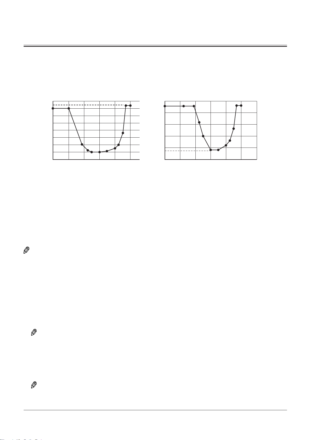
E
a b
B
D
C
A
E
B
C, D
A
SECTION 2 SYSTEM
Group 2 Control System
Speed Limit Control with Power Mode OFF
Purpose:
The speed limit control with power mode OFF limits the maximum engine speed of the engine according to driving load
with the power mode set to OFF. Therefore, fuel consumption is reduced.
TNFQ-02-02-014-1 ja
A- Engine Speed
E- Specied Value (lower than 2nd speed: 1750 min-1, 3rd
Speed: 2040 min
-1
)
B- Driving Load a- Shift Speed: lower than 2nd speed
C- Specied Value (lower than 2nd speed: 2070 min-1, 3rd
Speed: 2230 min
-1
)
b- Shift Speed: Third Speed
D- Specied Value (lower than 2nd speed: 2050 min-1, 3rd
Speed: 2230 min
-1
)
Operation:
NOTE
The time when forward/reverse switch (36) is eective is explained as an example.
1. TCU (7) sends the speed shift signals of transmission (8) to MC (3) by using CAN communication (17).
2. ECM (5) receives the signals from cam angle sensor (24) and crank speed sensor (23).
3. ECM (5) calculates them and sends a signal corresponding to the actual engine speed to MC (3) by using CAN
communication (17).
4. When all following conditions exist, MC (3) sends the signal equivalent to the target engine speed to ECM (5) by using
CAN communication (17).
• Forward/reverse lever (32) or forward/reverse switch (36): Forward position (33) or reverse position (35)
• Power mode: OFF
NOTE
When key switch (47) is set to the OFF position and then set back to the ON position, the power mode is turned OFF.
5. ECM (5) limits the engine speed to the specied value according to CAN communication (17).
• When the speed shift signal is third speed or lower, the engine speed is decreased and limited to the specied
value from the maximum rotation speed of the engine according to driving load.
• When the speed shift signal is fourth speed, the engine speed is limited to the maximum rotation speed.
NOTE
MC (3) detects driving load by using the torque converter speed ratio. The torque converter speed ratio is calculated
from the following equation.
TONFQ50-EN-00(28/02/2022)
T2-2-19
Page 80

2
1
83
75
5251 5355 54
32
33 34 35 88
36
33 34 35
48
31
69
71
72
80
73
70
84
86
20
37
43
15
14
74
17
63
3
MC
19
18
60
16
44
7
TCU
9
PLCU
4
5
ECM
13
11
10
64
46
21
38
25
24
23
22
26
27
29
28
30
6
8
41
47
SECTION 2 SYSTEM
Group 2 Control System
J=K/L
J- Torque Converter Speed Ratio
K- Torque Converter Output Shaft Speed
L- Actual engine speed
NOTE
Forward/reverse switch (36) is also equipped on machines mounted with the joystick steering system. Forward/reverse
switch (36) on the joystick steering system side is shifted between operable and inoperable by the joystick steering
selector switch (88).
TNFQ-02-02-015-1 ja
TONFQ50-EN-00(28/02/2022)
T2-2-20
Page 81
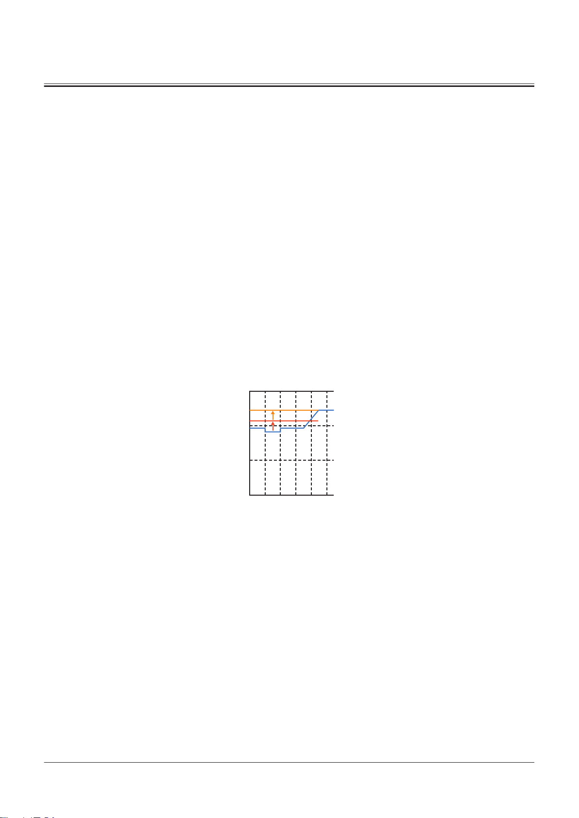
A
B
D,E
C
SECTION 2 SYSTEM
Group 2 Control System
1- Accelerator Pedal
2- Accelerator Pedal Sensor
3- MC
4- Monitor Controller
5- ECM
6- Engine
7- TCU
8- Transmission
9- PLCU
10- Main Monitor
11- Column Display
13- Control Lever
14- Rotary Device
15- Panel Switch 1
16- Panel Switch 2
17- Power-CAN
18- Body-CAN
19- PL-CAN
20- SENSOR-CAN
21- IF-CAN
22- Boost Temperature Sensor
23- Crank Speed Sensor
24- Cam Angle Sensor
25- Coolant Temperature Sensor
26- Torque Converter Oil Temper
ature Sensor
27- Torque Converter Input Shaft
Speed Sensor
28- Torque Converter Output
Shaft Speed Sensor
29- Transmission Intermediate
Shaft Speed Sensor
30- Vehicle Speed Sensor
31- Shift Switch
32- Forward/Reverse Lever
33- Forward Position
34- Neutral Position
35- Reverse Position
36- Forward/Reverse Switch
37- Forward/Reverse Selector
Switch
38- Pump Delivery Pressure Sen
sor
41- Parking Brake Pressure Sensor
43- Clutch Cut-o Position Switch
44- Power Mode Switch
46- Sub Monitor
47- Key Switch
48- Hydraulic Oil Temperature
Sensor
51- Brake Pedal (Left)
52- Service Brake Secondary Pres
sure Sensor
53- Brake Pedal (Right)
54- Brake Pedal (Right) Switch
55- Brake Pedal Position Sensor
60- Manual Regeneration Switch
63- Aftertreatment Device Regen
eration Signal
64- MPDr.
69- Lift Arm Angle Sensor
70- Bucket Angle Sensor
71- Axle Oil Temperature Sensor
72- Lift Arm Rod Pressure Sensor
73- Lift Arm Bottom Pressure Sen
sor
74- Position Sensor
75- Control Lever Lock Switch
80- Downshift Switch
83- Primary Pilot Pressure Sensor
84- Service Brake Primary Pres
sure Sensor
86- Object Detection Sensor
88- Joystick Steering Selector
Switch
Auto Power Up Speed Control
Purpose:
Auto power up speed control increases the maximum engine speed when the driving load increases, for example, when
climbing on a slope while speed limit control with power mode OFF is activated. Therefore, acceleration while climbing a
slope is improved.
TNFQ-02-02-016-1 ja
A- Engine Speed D- Specied Value (specied value (E) not exceeded by 150
min-1 increase from engine demand speed during opera
tion)
B- Driving Load
E- Specied Value (F1/F2: 2000 min-1, F3/R1/R2: 2100 min-1,
R3: 2230 min
-1
)
C- Specied Value (specied value (E) not exceeded by 150
min-1 increase from engine demand speed during opera
tion)
Operation:
1. Position sensor (74) sends the vehicle position angle signal to MC (3) by using CAN communication (20). At the same
time, TCU (7) sends the signal equivalent to the command transmission speed to MC (3) by using CAN communication
(17).
2. When speed limit control with power mode OFF is activated, MC (3) calculates the signal from TCU (7) and the signal
from position sensor (74) internally to calculate the signal equivalent to the target engine speed. MC (3) sends the
signal equivalent to the target engine speed to ECM (5) by using CAN communication (17).
TONFQ50-EN-00(28/02/2022)
T2-2-21
Page 82

SECTION 2 SYSTEM
Group 2 Control System
NOTE
When key switch (47) is set to the OFF position, the power mode is turned OFF.
3. any of the following conditions 1, 2 or 3 exists, ECM (5) increases the engine speed to specied value (C), specied
value (D) or specied value (E) corresponding to the condition.
Description of Conditions Target Engine Speed
Condition 1 Torque converter speed ratio is held for a specied range (Ref
erence: more than 0.4 and less than 0.7) for a specied time
(speed 1 to speed 3 reference: for 1 second)
Condition 2 Torque converter speed ratio is held for a specied range (Ref
erence: more than 0.4 and less than 0.7) for a specied time
(speed 1 to speed 3 reference: for 1.5 seconds)
Condition 3 Command transmission speed is in forward direction and the
estimated vehicle position angle is held for 1 second over the
specied value (Reference: 5°) or the command transmission
speed is in the reverse direction and the estimated vehicle po
sition angle is held for 1 second less than the specied value
(Reference: -5°)
Specied value (C): Specied value (E)
not exceeded by 150 min-1 increase
from engine demand speed during op
eration)
Specied value (D): Specied value (E)
not exceeded by 150 min-1 increase
from engine demand speed during op
eration)
Specied value (E)
NOTE
MC (3) detects driving load by using the torque converter speed ratio. The torque converter speed ratio is calculated
from the following equation.
J=K/L
J- Torque Converter Speed Ratio L- Actual Engine Speed
K- Torque Converter Output Shaft Speed
Deactivation:
NOTE
The time when forward/reverse switch (36) is eective is explained as an example.
1. When following conditions 1, 2 or 3 exist, MC (3) deactivates the auto power up speed control.
Engine Speed During Op
eration
Condition 1 Specied value (C)
Condition 2 Specied value (D) Torque converter speed ratio is held for a specied range (Reference: 0.9 or
Condition 3 Specied value (E) The estimated vehicle position angle is held in the specied range (Refer
When the engine speed (specied value (C)) that has increased 150 min-1 is
less than the engine speed with the power mode set at OFF, forward/
reverse lever (32): operated, forward/reverse switch (36): operated or accel
erator pedal (1): neutral position
more) for 2 seconds, forward/reverse lever (32): operated, forward/reverse
switch (36): operated or accelerator pedal (1): neutral position
ence: -3° to 3°) for 1.5 seconds
Description of Conditions
NOTE
Forward/reverse switch (36) is also equipped on machines mounted with the joystick steering system. Forward/reverse
switch (36) on the joystick steering system side is shifted between operable and inoperable by joystick steering selector
switch (88).
TONFQ50-EN-00(28/02/2022)
T2-2-22
Page 83

2
1
83
75
5251 5355 54
32
33 34 35 88
36
33 34 35
48
31
69
71
72
80
73
70
84
86
20
37
43
15
14
74
17
63
3
MC
19
18
60
16
44
7
TCU
9
PLCU
4
5
ECM
13
11
10
64
46
21
38
25
24
23
22
26
27
29
28
30
6
8
41
47
SECTION 2 SYSTEM
Group 2 Control System
1- Accelerator Pedal
2- Accelerator Pedal Sensor
3- MC
4- Monitor Controller
5- ECM
6- Engine
7- TCU
8- Transmission
9- PLCU
10- Main Monitor
11- Column Display
13- Control Lever
14- Rotary Device
15- Panel Switch 1
16- Panel Switch 2
17- Power-CAN
18- Body-CAN
19- PL-CAN
20- SENSOR-CAN
21- IF-CAN
22- Boost Temperature Sensor
23- Crank Speed Sensor
24- Cam Angle Sensor
25- Coolant Temperature Sensor
26- Torque Converter Oil Temper
27- Torque Converter Input Shaft
28- Torque Converter Output
29- Transmission Intermediate
30- Vehicle Speed Sensor
31- Shift Switch
32- Forward/Reverse Lever
33- Forward Position
34- Neutral Position
35- Reverse Position
ature Sensor
Speed Sensor
Shaft Speed Sensor
Shaft Speed Sensor
36- Forward/Reverse Switch
37- Forward/Reverse Selector
Switch
38- Pump Delivery Pressure Sen
sor
41- Parking Brake Pressure Sensor
43- Clutch Cut-o Position Switch
44- Power Mode Switch
46- Sub Monitor
47- Key Switch
48- Hydraulic Oil Temperature
Sensor
51- Brake Pedal (Left)
52- Service Brake Secondary Pres
sure Sensor
53- Brake Pedal (Right)
54- Brake Pedal (Right) Switch
55- Brake Pedal Position Sensor
60- Manual Regeneration Switch
TNFQ-02-02-017-1 ja
63- Aftertreatment Device Regen
eration Signal
64- MPDr.
69- Lift Arm Angle Sensor
70- Bucket Angle Sensor
71- Axle Oil Temperature Sensor
72- Lift Arm Rod Pressure Sensor
73- Lift Arm Bottom Pressure Sen
sor
74- Position Sensor
75- Control Lever Lock Switch
80- Downshift Switch
83- Primary Pilot Pressure Sensor
84- Service Brake Primary Pres
sure Sensor
86- Object Detection Sensor
88- Joystick Steering Selector
Switch
TONFQ50-EN-00(28/02/2022)
T2-2-23
Page 84

A
B
CD
F
G
E
SECTION 2 SYSTEM
Group 2 Control System
Overheat Prevention Speed Limit Control
Purpose:
The overheat prevention speed limit control limits the maximum engine speed of the engine and prevents the engine
overheating when the coolant temperature, hydraulic oil temperature, torque converter oil temperature, or axle oil
temperature increases to the upper limit.
TNUD-02-02-020-1 ja
A- Engine Speed E- Axle Oil Temperature (110 °C)/Torque Converter Oil Tem
perature (112 °C)
B- Temperature F- Maximum Rotation Speed
C- Hydraulic Oil Temperature (93 °C) G- Specied Value (Limited According to Coolant Tempera
ture/Axle Oil Temperature: 2070 min-1, Limited According to
Hydraulic Oil Temperature/Torque Converter Oil Tempera
ture: 2000 min-1)
D- Coolant Temperature (104 °C)
Operation:
1. ECM (5) sends the signal from coolant temperature sensor (25) to MC (3) by using CAN communication (17).
2. TCU (7) sends the signal from the torque converter oil temperature sensor (26) to MC (3) by using CAN communication
(17).
3. MC (3) receives the signals from the hydraulic oil temperature sensor (48) and axle oil temperature sensor (71).
4. any of the following conditions exists, MC (3) sends the signal equivalent to the target engine speed to ECM (5) by
using CAN communication (17).
• Coolant Temperature: 104 °C or more
• Torque Converter Oil Temperature: 112 °C or more
• Hydraulic oil temperature: 93 °C or more
• Axle Oil Temperature: 110 °C or more
5. ECM (5) limits the engine speed to specied value (G) according to CAN communication (17).
TONFQ50-EN-00(28/02/2022)
T2-2-24
Page 85

2
1
83
75
5251 5355 54
32
33 34 35 88
36
33 34 35
48
31
69
71
72
80
73
70
84
86
20
37
43
15
14
74
17
63
3
MC
19
18
60
16
44
7
TCU
9
PLCU
4
5
ECM
13
11
10
64
46
21
38
25
24
23
22
26
27
29
28
30
6
8
41
47
SECTION 2 SYSTEM
Group 2 Control System
1- Accelerator Pedal
2- Accelerator Pedal Sensor
3- MC
4- Monitor Controller
5- ECM
6- Engine
7- TCU
8- Transmission
9- PLCU
10- Main Monitor
11- Column Display
13- Control Lever
14- Rotary Device
15- Panel Switch 1
16- Panel Switch 2
17- Power-CAN
18- Body-CAN
19- PL-CAN
20- SENSOR-CAN
21- IF-CAN
22- Boost Temperature Sensor
23- Crank Speed Sensor
24- Cam Angle Sensor
25- Coolant Temperature Sensor
26- Torque Converter Oil Temper
27- Torque Converter Input Shaft
28- Torque Converter Output
29- Transmission Intermediate
30- Vehicle Speed Sensor
31- Shift Switch
32- Forward/Reverse Lever
33- Forward Position
34- Neutral Position
35- Reverse Position
ature Sensor
Speed Sensor
Shaft Speed Sensor
Shaft Speed Sensor
36- Forward/Reverse Switch
37- Forward/Reverse Selector
Switch
38- Pump Delivery Pressure Sen
sor
41- Parking Brake Pressure Sensor
43- Clutch Cut-o Position Switch
44- Power Mode Switch
46- Sub Monitor
47- Key Switch
48- Hydraulic Oil Temperature
Sensor
51- Brake Pedal (Left)
52- Service Brake Secondary Pres
sure Sensor
53- Brake Pedal (Right)
54- Brake Pedal (Right) Switch
55- Brake Pedal Position Sensor
60- Manual Regeneration Switch
TNFQ-02-02-021-1 ja
63- Aftertreatment Device Regen
eration Signal
64- MPDr.
69- Lift Arm Angle Sensor
70- Bucket Angle Sensor
71- Axle Oil Temperature Sensor
72- Lift Arm Rod Pressure Sensor
73- Lift Arm Bottom Pressure Sen
sor
74- Position Sensor
75- Control Lever Lock Switch
80- Downshift Switch
83- Primary Pilot Pressure Sensor
84- Service Brake Primary Pres
sure Sensor
86- Object Detection Sensor
88- Joystick Steering Selector
Switch
TONFQ50-EN-00(28/02/2022)
T2-2-25
Page 86

SECTION 2 SYSTEM
Group 2 Control System
Aftertreatment Device Manual Regeneration Control
Purpose:
The aftertreatment device manual regeneration control increases the engine speed and applies load to the engine.
Therefore, this control assists to increase the exhaust temperature up to the temperature that a catalyst in the
aftertreatment device is activated.
Operation:
NOTE
The time when forward/reverse switch (36) is eective is explained as an example.
1. When manual regeneration of the aftertreatment device is required, ECM (5) sends the aftertreatment device
regeneration request signal to MC (3) by using CAN communication (17). (Refer to "Aftertreatment Device
Regeneration Control"T2-3-21.)
2. When all following conditions exist, MC (3) sends aftertreatment device regeneration request signal (63) to ECM (5).
• Manual regeneration switch (60):ON
• Accelerator Pedal (1): Not operated
• Parking Brake: Operation
• Forward/Reverse Lever (32) and Forward/Reverse Switch (36): Neutral Position (34)
• Control Lever Lock: Operation (primary pilot pressure sensor (83) at less than specied value by control lever lock
switch (ON))
3. ECM (5) increases the engine speed and increases the exhaust temperature up to the temperature that a catalyst in
the aftertreatment device is activated.
NOTE
Forward/reverse switch (36) is also equipped on machines mounted with the joystick steering system. Forward/reverse
switch (36) on the joystick steering system side is shifted between operable and inoperable by joystick steering selector
switch (88).
TONFQ50-EN-00(28/02/2022)
T2-2-26
Page 87

2
1
83
75
5251 5355 54
32
33 34 35 88
36
33 34 35
48
31
69
71
72
80
73
70
84
86
20
37
43
15
14
74
17
63
3
MC
19
18
60
16
44
7
TCU
9
PLCU
4
5
ECM
13
11
10
64
46
21
38
25
24
23
22
26
27
29
28
30
6
8
41
47
SECTION 2 SYSTEM
Group 2 Control System
1- Accelerator Pedal
2- Accelerator Pedal Sensor
3- MC
4- Monitor Controller
5- ECM
6- Engine
7- TCU
8- Transmission
9- PLCU
10- Main Monitor
11- Column Display
13- Control Lever
14- Rotary Device
15- Panel Switch 1
16- Panel Switch 2
17- Power-CAN
18- Body-CAN
19- PL-CAN
20- SENSOR-CAN
21- IF-CAN
22- Boost Temperature Sensor
23- Crank Speed Sensor
24- Cam Angle Sensor
25- Coolant Temperature Sensor
26- Torque Converter Oil Temper
27- Torque Converter Input Shaft
28- Torque Converter Output
29- Transmission Intermediate
30- Vehicle Speed Sensor
31- Shift Switch
32- Forward/Reverse Lever
33- Forward Position
34- Neutral Position
35- Reverse Position
ature Sensor
Speed Sensor
Shaft Speed Sensor
Shaft Speed Sensor
36- Forward/Reverse Switch
37- Forward/Reverse Selector
Switch
38- Pump Delivery Pressure Sen
sor
41- Parking Brake Pressure Sensor
43- Clutch Cut-o Position Switch
44- Power Mode Switch
46- Sub Monitor
47- Key Switch
48- Hydraulic Oil Temperature
Sensor
51- Brake Pedal (Left)
52- Service Brake Secondary Pres
sure Sensor
53- Brake Pedal (Right)
54- Brake Pedal (Right) Switch
55- Brake Pedal Position Sensor
60- Manual Regeneration Switch
TNFQ-02-02-024-1 ja
63- Aftertreatment Device Regen
eration Signal
64- MPDr.
69- Lift Arm Angle Sensor
70- Bucket Angle Sensor
71- Axle Oil Temperature Sensor
72- Lift Arm Rod Pressure Sensor
73- Lift Arm Bottom Pressure Sen
sor
74- Position Sensor
75- Control Lever Lock Switch
80- Downshift Switch
83- Primary Pilot Pressure Sensor
84- Service Brake Primary Pres
sure Sensor
86- Object Detection Sensor
88- Joystick Steering Selector
Switch
TONFQ50-EN-00(28/02/2022)
T2-2-27
Page 88

SECTION 2 SYSTEM
Group 2 Control System
Engine Over Speed Limit Control
Purpose:
Engine overload prevention control activates the exhaust brake mounted on the engine when the engine speed has risen
above the allowable value, for example, when traveling down slopes. Therefore, the engine speed is reduced to prevent
damage to the hydraulic pump and transmission.
Operation:
NOTE
The time when forward/reverse switch (36) is eective is explained as an example.
1. Position sensor (74) sends the vehicle position angle signal to MC (3) by using CAN communication (20).
2. PLCU (9) receives the signals (the demand engine speed) from accelerator pedal sensor (2) and sends them to MC (3)
by using CAN communication (17). At the same time, PLCU (9) receives the signals from forward/reverse lever (32) and
sends them to TCU (7) by using CAN communication (17).
3. TCU (7) sends the vehicle speed signal, transmission speed shift signal, and current FNR command signal to MC (3) by
using CAN communication (17).
4. ECM (5) receives the signals from cam angle sensor (24) and crank speed sensor (23).
5. ECM (5) calculates them and sends a signal corresponding to the actual engine speed to MC (3) by using CAN
communication (17).
6. When any of following conditions 1, 2 or 3 exists, MC (3) sends the exhaust brake operation signal to ECM (5) by using
CAN communication (17).
Accelerator pedal
(1)
Condition 1- Forward position (33) or
Condition 2Not Operated - - Judgment condition A or
Condition 3Operation - Specied value or less held
Judgment condition A: When all following conditions exist
• Engine speed calculated value is 2100 min-1 or more
• Engine speed rate of change is over specied value
• Transmission output speed rate of change is over specied value and engine torque is 5% or less
Judgment Condition B: When all following conditions exist
• Engine speed calculated value is 2350 min-1 or more and engine torque is 5% or less
• Transmission output speed rate of change is over specied value and 2.5 seconds has elapsed after shift down
7. ECM (5) activates the exhaust brake.
Deactivation:
1. When either of following condition 1 or condition 2 exists, ECM (5) deactivates the exhaust brake
Forward/reverse lever (32)
or forward/reverse switch
(36)
reverse position (35)
Position sensor (74) Judgment condition
Specied value or more held
for 1 second
for 1 second
Judgment condition A or
judgment condition B exist.
judgment condition B exist.
Judgment condition B exist.
Accelerator pedal (1) Engine speed calculated value: Transmission Output Speed
Condition 1 Not Operated
Condition 2 Operated
TONFQ50-EN-00(28/02/2022)
1600 min-1 or less
2100 min-1 or less
T2-2-28
Threshold value corresponding to command
transmission speed or less
Threshold value corresponding to command
transmission speed or less
Page 89
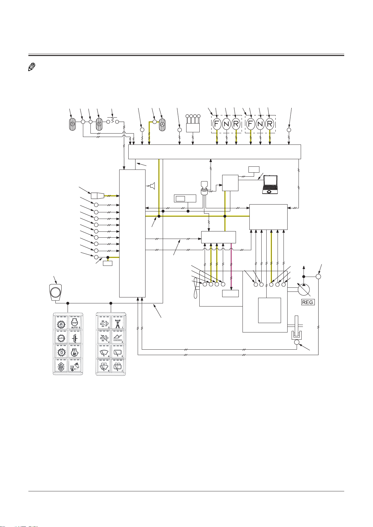
2
1
83
75
5251 5355 54
32
33 34 35 88
36
33 34 35
48
31
69
71
72
80
73
70
84
86
20
37
43
15
14
74
17
63
3
MC
19
18
60
16
44
7
TCU
9
PLCU
4
5
ECM
13
11
10
64
46
21
38
25
24
23
22
26
27
29
28
30
6
8
41
47
SECTION 2 SYSTEM
Group 2 Control System
NOTE
Forward/reverse switch (36) is also equipped on machines mounted with the joystick steering system. Forward/reverse
switch (36) on the joystick steering system side is shifted between operable and inoperable by joystick steering selector
switch (88).
TNFQ-02-02-025-1 ja
TONFQ50-EN-00(28/02/2022)
T2-2-29
Page 90

SECTION 2 SYSTEM
Group 2 Control System
1- Accelerator Pedal
2- Accelerator Pedal Sensor
3- MC
4- Monitor Controller
5- ECM
6- Engine
7- TCU
8- Transmission
9- PLCU
10- Main Monitor
11- Column Display
13- Control Lever
14- Rotary Device
15- Panel Switch 1
16- Panel Switch 2
17- Power-CAN
18- Body-CAN
19- PL-CAN
20- SENSOR-CAN
21- IF-CAN
22- Boost Temperature Sensor
23- Crank Speed Sensor
24- Cam Angle Sensor
25- Coolant Temperature Sensor
26- Torque Converter Oil Temper
ature Sensor
27- Torque Converter Input Shaft
Speed Sensor
28- Torque Converter Output
Shaft Speed Sensor
29- Transmission Intermediate
Shaft Speed Sensor
30- Vehicle Speed Sensor
31- Shift Switch
32- Forward/Reverse Lever
33- Forward Position
34- Neutral Position
35- Reverse Position
36- Forward/Reverse Switch
37- Forward/Reverse Selector
Switch
38- Pump Delivery Pressure Sen
sor
41- Parking Brake Pressure Sensor
43- Clutch Cut-o Position Switch
44- Power Mode Switch
46- Sub Monitor
47- Key Switch
48- Hydraulic Oil Temperature
Sensor
51- Brake Pedal (Left)
52- Service Brake Secondary Pres
sure Sensor
53- Brake Pedal (Right)
54- Brake Pedal (Right) Switch
55- Brake Pedal Position Sensor
60- Manual Regeneration Switch
63- Aftertreatment Device Regen
eration Signal
64- MPDr.
69- Lift Arm Angle Sensor
70- Bucket Angle Sensor
71- Axle Oil Temperature Sensor
72- Lift Arm Rod Pressure Sensor
73- Lift Arm Bottom Pressure Sen
sor
74- Position Sensor
75- Control Lever Lock Switch
80- Downshift Switch
83- Primary Pilot Pressure Sensor
84- Service Brake Primary Pres
sure Sensor
86- Object Detection Sensor
88- Joystick Steering Selector
Switch
Engine Max. Speed Limit Control at Stroke End Stall and Front Relief
Purpose:
Maximum engine speed limit control during brake stalling and front attachment relief limits the engine speed to reduce
fuel consumption when brake stalling and front relief operations are performed with the lift arm or bucket cylinder at the
stroke end.
Operation:
1. When all following conditions exist, ECM (5) lowers the engine speed to 1650 min-1.
• Accelerator pedal (1): Operated
• Brake pedals (51, 53): Operated
• Torque converter speed ratio: specied value or less
• Pump delivery pressure sensor (38): specied value or more
• Lift arm or bucket: Relief operation
NOTE
The torque converter speed ratio is calculated from the following equation.
J=K/L
J- Torque Converter Speed Ratio L- Actual Engine Speed
K- Torque Converter Output Shaft Speed
Deactivation:
1. When any of the following conditions exists, MC (5) deactivates maximum engine speed limit control during brake
stalling and front attachment relief.
• Accelerator pedal (1): Not operated
• Brake pedals (51, 53): Not operated
• Torque converter speed ratio: specied value or more
• Pump delivery pressure sensor (38): Specied value or less
• Lift arm or bucket: Relief
TONFQ50-EN-00(28/02/2022)
T2-2-30
Page 91
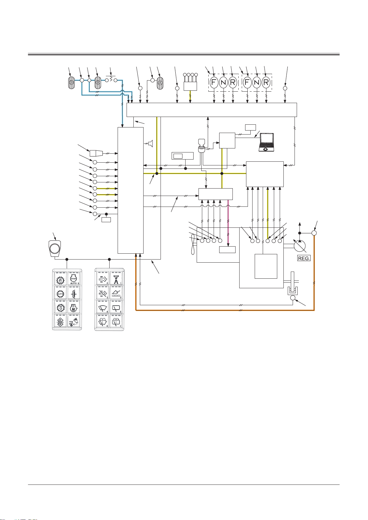
2
1
83
75
5251 5355 54
32
33 34 35 88
36
33 34 35
48
31
69
71
72
80
73
70
84
86
20
37
43
15
14
74
17
63
3
MC
19
18
60
16
44
7
TCU
9
PLCU
4
5
ECM
13
11
10
64
46
21
38
25
24
23
22
26
27
29
28
30
6
8
41
47
SECTION 2 SYSTEM
Group 2 Control System
1- Accelerator Pedal
2- Accelerator Pedal Sensor
3- MC
4- Monitor Controller
5- ECM
6- Engine
7- TCU
8- Transmission
9- PLCU
10- Main Monitor
11- Column Display
13- Control Lever
14- Rotary Device
15- Panel Switch 1
16- Panel Switch 2
17- Power-CAN
18- Body-CAN
19- PL-CAN
20- SENSOR-CAN
21- IF-CAN
22- Boost Temperature Sensor
23- Crank Speed Sensor
24- Cam Angle Sensor
25- Coolant Temperature Sensor
26- Torque Converter Oil Temper
27- Torque Converter Input Shaft
28- Torque Converter Output
29- Transmission Intermediate
30- Vehicle Speed Sensor
31- Shift Switch
32- Forward/Reverse Lever
33- Forward Position
34- Neutral Position
35- Reverse Position
ature Sensor
Speed Sensor
Shaft Speed Sensor
Shaft Speed Sensor
36- Forward/Reverse Switch
37- Forward/Reverse Selector
Switch
38- Pump Delivery Pressure Sen
sor
41- Parking Brake Pressure Sensor
43- Clutch Cut-o Position Switch
44- Power Mode Switch
46- Sub Monitor
47- Key Switch
48- Hydraulic Oil Temperature
Sensor
51- Brake Pedal (Left)
52- Service Brake Secondary Pres
sure Sensor
53- Brake Pedal (Right)
54- Brake Pedal (Right) Switch
55- Brake Pedal Position Sensor
60- Manual Regeneration Switch
TNFQ-02-02-026-1 ja
63- Aftertreatment Device Regen
eration Signal
64- MPDr.
69- Lift Arm Angle Sensor
70- Bucket Angle Sensor
71- Axle Oil Temperature Sensor
72- Lift Arm Rod Pressure Sensor
73- Lift Arm Bottom Pressure Sen
sor
74- Position Sensor
75- Control Lever Lock Switch
80- Downshift Switch
83- Primary Pilot Pressure Sensor
84- Service Brake Primary Pres
sure Sensor
86- Object Detection Sensor
88- Joystick Steering Selector
Switch
TONFQ50-EN-00(28/02/2022)
T2-2-31
Page 92
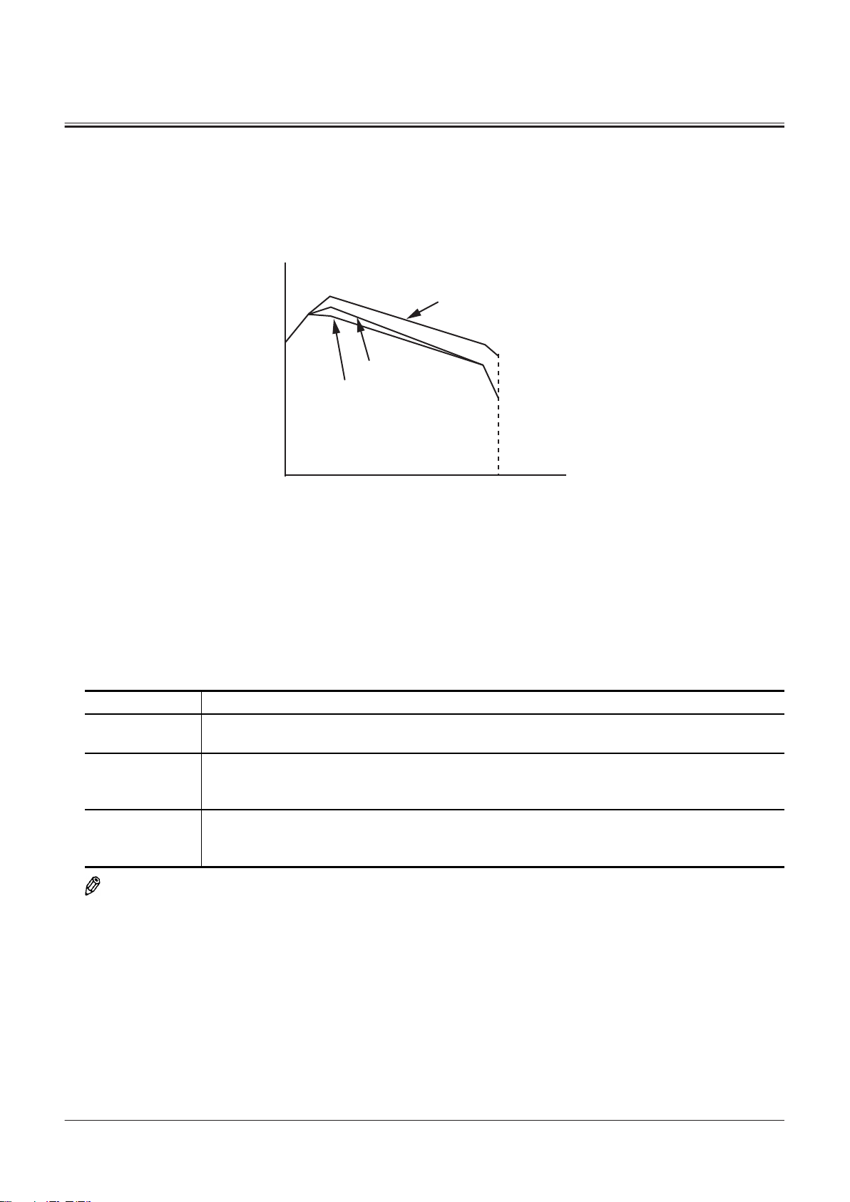
A
BDC
G
F
E
SECTION 2 SYSTEM
Group 2 Control System
Engine Torque Limit Control During Acceleration
Purpose:
Engine torque limit control during acceleration limits the engine torque during travel to control unnecessary acceleration.
Therefore, fuel consumption is reduced.
TNFQ-02-02-100-1 ja
A- Engine Torque E- No Restriction
B- Engine Speed F- Engine Torque Restriction Level 1
C- Minimum Rotation Speed G- Engine Torque Restriction Level 2
D- Maximum Rotation Speed
Operation:
1. When following condition 1 and condition 2 exist, and condition 3 does not exist,, MC (3) sends the signal equivalent
to engine torque restriction level 2 to ECM (5) by using CAN communication (17).
Description of Conditions
Condition 1 Axle oil temperature is at the specied value (Reference: 40 °C) or more, and the estimated vehicle
position angle is less than the specied value
Condition 2 Vehicle Speed: 12 km/h or more, and the transmission speed: 3rd speed range or higher or the
transmission speed 2nd speed range or higher when in an operation position and the torque con
verter speed ratio is at the specied value (Reference: 70%) or more
Condition 3 Power mode: ON, accelerator pedal: depressing (Reference: 75% or more) and the estimated vehi
cle position angle is in the specied range (Reference: 4° or more (when transmission is forward)
or reference: 4° or less (when transmission is reverse))
NOTE
MC (3) detects driving load by using the torque converter speed ratio. The torque converter speed ratio is calculated
from the following equation.
J=K/L
J- Torque Converter Speed Ratio L- Actual Engine Speed
K- Torque Converter Output Shaft Speed
2. ECM (5) limits the engine torque according to the engine speed.
3. When any of the following conditions exists, MC (3) sends the signal equivalent to engine torque restriction level 1 to
ECM (5) by using CAN communication (17).
TONFQ50-EN-00(28/02/2022)
T2-2-32
Page 93
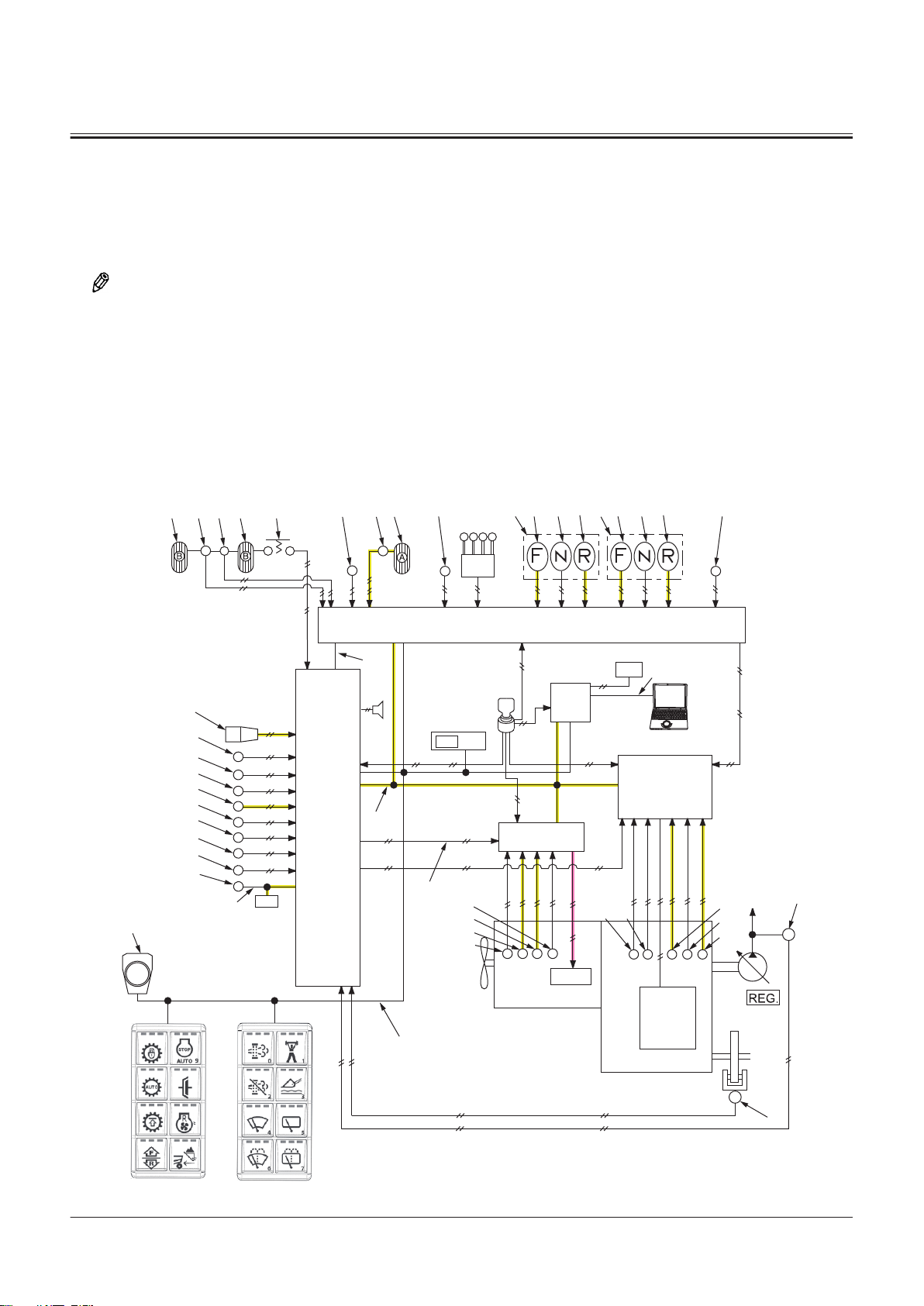
2
1
83
75
5251 5355 54
32
33 34 35 88
36
33 34 35
48
31
69
71
72
80
73
70
84
86
20
37
43
15
14
74
17
63
3
MC
19
18
60
16
44
7
TCU
9
PLCU
4
5
ECM
13
11
10
64
46
21
38
25
24
23
22
26
27
29
28
30
6
8
41
47
SECTION 2 SYSTEM
Group 2 Control System
• When accelerator pedal (1) is not depressed: transmission output speed rate of change is specied value
(Reference: -500 min-1) or less continuously for over the specied time (Reference: 1 second) or more
• When accelerator pedal (1) is depressed: transmission output speed rate of change is specied value (Reference:
-100 min-1) or less continuously for over the specied time (Reference: 0.5 seconds)
4. ECM (5) limits the engine torque according to the engine speed.
NOTE
When any of the conditions in step 3 exists again, MC (3) sends the signal corresponding to engine torque restriction
suspend to ECM (5), and engine torque restriction is suspended.
5. When all following conditions exist, MC (3) sends the signals equivalent to engine torque restriction level 2 to ECM (5)
by using CAN communication (17).
• transmission output speed rate of change is specied value (Reference: 100 min-1) continuously for over the
specied time (Reference: 1 second)
• The estimated vehicle position angle is the specied range (Reference: -2° to 2°) continuously for over the specied
time (Reference: 1 second)
6. ECM (5) limits the engine torque according to the engine speed.
TONFQ50-EN-00(28/02/2022)
T2-2-33
TNFQ-02-02-101-1 ja
Page 94

SECTION 2 SYSTEM
Group 2 Control System
1- Accelerator Pedal
2- Accelerator Pedal Sensor
3- MC
4- Monitor Controller
5- ECM
6- Engine
7- TCU
8- Transmission
9- PLCU
10- Main Monitor
11- Column Display
13- Control Lever
14- Rotary Device
15- Panel Switch 1
16- Panel Switch 2
17- Power-CAN
18- Body-CAN
19- PL-CAN
20- SENSOR-CAN
21- IF-CAN
22- Boost Temperature Sensor
23- Crank Speed Sensor
24- Cam Angle Sensor
25- Coolant Temperature Sensor
26- Torque Converter Oil Temper
ature Sensor
27- Torque Converter Input Shaft
Speed Sensor
28- Torque Converter Output
Shaft Speed Sensor
29- Transmission Intermediate
Shaft Speed Sensor
30- Vehicle Speed Sensor
31- Shift Switch
32- Forward/Reverse Lever
33- Forward Position
34- Neutral Position
35- Reverse Position
Pump Control
The pump control consists of the followings.
● Basic Torque Control
● Torque Decrease Control While Digging
36- Forward/Reverse Switch
37- Forward/Reverse Selector
Switch
38- Pump Delivery Pressure Sen
sor
41- Parking Brake Pressure Sensor
43- Clutch Cut-o Position Switch
44- Power Mode Switch
46- Sub Monitor
47- Key Switch
48- Hydraulic Oil Temperature
Sensor
51- Brake Pedal (Left)
52- Service Brake Secondary Pres
sure Sensor
53- Brake Pedal (Right)
54- Brake Pedal (Right) Switch
55- Brake Pedal Position Sensor
60- Manual Regeneration Switch
63- Aftertreatment Device Regen
eration Signal
64- MPDr.
69- Lift Arm Angle Sensor
70- Bucket Angle Sensor
71- Axle Oil Temperature Sensor
72- Lift Arm Rod Pressure Sensor
73- Lift Arm Bottom Pressure Sen
sor
74- Position Sensor
75- Control Lever Lock Switch
80- Downshift Switch
83- Primary Pilot Pressure Sensor
84- Service Brake Primary Pres
sure Sensor
86- Object Detection Sensor
88- Joystick Steering Selector
Switch
TONFQ50-EN-00(28/02/2022)
T2-2-34
Page 95
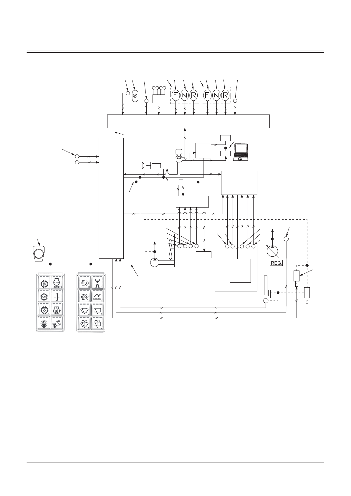
Pump Control System Layout
2
1
75
32
33 34 35 88
36
33 34 35
48
37
15
14
17
19
18
16
9
PLCU
7
TCU
5
ECM
3
MC
4
13
11
10
64
46
50
21
38
25
24
23
22
26
27
29
28
30
6
8
39
47
SECTION 2 SYSTEM
Group 2 Control System
1- Accelerator Pedal
2- Accelerator Pedal Sensor
3- MC
4- Monitor Controller
5- ECM
6- Engine
7- TCU
8- Transmission
9- PLCU
10- Main Monitor
11- Column Display
13- Control Lever
14- Rotary Device
15- Panel Switch 1
16- Panel Switch 2
17- Power-CAN
18- Body-CAN
19- PL-CAN
21- IF-CAN
22- Boost Temperature Sensor
23- Crank Speed Sensor
24- Cam Angle Sensor
25- Coolant Temperature Sensor
26- Torque Converter Oil Temper
ature Sensor
27- Torque Converter Input Shaft
Speed Sensor
28- Torque Converter Output
Shaft Speed Sensor
29- Transmission Intermediate
Shaft Speed Sensor
30- Vehicle Speed Sensor
32- Forward/Reverse Lever
33- Forward Position
34- Neutral Position
35- Reverse Position
36- Forward/Reverse Switch
TNFQ-02-02-203-1 ja
37- Forward/Reverse Selector
Switch
38- Pump Delivery Pressure Sen
sor
39- Torque Control Solenoid Valve
46- Sub Monitor
47- Key Switch
48- Hydraulic Oil Temperature
Sensor
50- GSM
64- MPDr.
75- Control Lever Lock Switch
88- Joystick Steering Selector
Switch
TONFQ50-EN-00(28/02/2022)
T2-2-35
Page 96

A
B
C
E
D
F
SECTION 2 SYSTEM
Group 2 Control System
Base Torque Control
Purpose:
The base torque control controls the pump delivery ow rate in response to the engine speed changes due to variations
in load. Then, the engine torque can be utilized more eciently.
TNUD-02-02-027-1 ja
A- Pump Torque Reading (Nm) D- Hydraulic Oil Temperature (Low)
B- Actual Engine Speed (min-1)
C- Hydraulic Oil Temperature (High) F- Demand Engine Speed Level (High)
Operation:
1. The target engine speed can be set by the depressing amount of accelerator pedal (1). (Refer to "Accelerator Pedal
Control"T2-2-5.)
2. ECM (5) receives the signals from cam angle sensor (24) and crank speed sensor (23).
3. ECM (5) calculates them and sends a signal corresponding to the actual engine speed to MC (3) by using CAN
communication (17).
4. MC (3) compares the dierence between the target engine speed and the actual engine speed signal received from
ECM (5).
5. MC (3) activates torque control solenoid valve (39) according to the signal from hydraulic oil temperature sensor (48)
so that the engine speed becomes the target engine speed according to the hydraulic oil temperature.
6. The torque control solenoid valve (39) delivers the pilot pressure according to the signal to the regulator and controls
the pump delivery ow rate. Therefore, the engine load is reduced and the engine stall is prevented.
E- Demand Engine Speed Level (Low)
NOTE
While digging, refer to "Torque Decrease Control While Digging"T2-2-37.
TONFQ50-EN-00(28/02/2022)
T2-2-36
Page 97

2
1
75
32
33 34 35 88
36
33 34 35
48
37
15
14
17
19
18
16
9
PLCU
7
TCU
5
ECM
3
MC
4
13
11
10
64
46
50
21
38
25
24
23
22
26
27
29
28
30
6
8
39
47
SECTION 2 SYSTEM
Group 2 Control System
1- Accelerator Pedal
2- Accelerator Pedal Sensor
3- MC
4- Monitor Controller
5- ECM
6- Engine
7- TCU
8- Transmission
9- PLCU
10- Main Monitor
11- Column Display
13- Control Lever
14- Rotary Device
15- Panel Switch 1
16- Panel Switch 2
17- Power-CAN
18- Body-CAN
19- PL-CAN
21- IF-CAN
22- Boost Temperature Sensor
23- Crank Speed Sensor
24- Cam Angle Sensor
25- Coolant Temperature Sensor
26- Torque Converter Oil Temper
ature Sensor
27- Torque Converter Input Shaft
Speed Sensor
28- Torque Converter Output
Shaft Speed Sensor
29- Transmission Intermediate
Shaft Speed Sensor
30- Vehicle Speed Sensor
32- Forward/Reverse Lever
33- Forward Position
34- Neutral Position
35- Reverse Position
36- Forward/Reverse Switch
TNFQ-02-02-203-2 ja
37- Forward/Reverse Selector
Switch
38- Pump Delivery Pressure Sen
sor
39- Torque Control Solenoid Valve
46- Sub Monitor
47- Key Switch
48- Hydraulic Oil Temperature
Sensor
50- GSM
64- MPDr.
75- Control Lever Lock Switch
88- Joystick Steering Selector
Switch
Torque Decrease Control While Digging
Purpose:
The torque decrease control while digging reduces the pump delivery ow rate and reduces the pump driving torque.
Then, the engine torque can be utilized as the driving power. (Refer to "Matching Control While Digging"T2-2-16.)
TONFQ50-EN-00(28/02/2022)
T2-2-37
Page 98

SECTION 2 SYSTEM
Group 2 Control System
Operation:
NOTE
The time when forward/reverse switch (36) is eective is explained as an example.
1. When all following conditions exist, MC (3) activates torque control solenoid valve (39).
• Torque Converter Speed Ratio: less than specied value (Reference: 15% or less)
• Forward/Reverse Lever (32) or Forward/Reverse Switch (36): Forward Position (33)
• Pump Delivery Pressure: High Pressure (Reference: 13 MPa or more)
NOTE
The torque converter speed ratio is calculated from the following equation.
J=K/L
J- Torque Converter Speed Ratio
K- Torque Converter Output Shaft Speed
L- Actual engine speed
2. Torque control solenoid valve (39) delivers the pilot pressure oil according to the signals to the regulator and reduces
the pump delivery ow rate.
NOTE
Forward/reverse switch (36) is also equipped on machines mounted with the joystick steering system. Forward/reverse
switch (36) on the joystick steering system side is shifted between operable and inoperable by joystick steering selector
switch (88).
TONFQ50-EN-00(28/02/2022)
T2-2-38
Page 99

2
1
75
32
33 34 35 88
36
33 34 35
48
37
15
14
17
19
18
16
9
PLCU
7
TCU
5
ECM
3
MC
4
13
11
10
64
46
50
21
38
25
24
23
22
26
27
29
28
30
6
8
39
47
SECTION 2 SYSTEM
Group 2 Control System
1- Accelerator Pedal
2- Accelerator Pedal Sensor
3- MC
4- Monitor Controller
5- ECM
6- Engine
7- TCU
8- Transmission
9- PLCU
10- Main Monitor
11- Column Display
13- Control Lever
14- Rotary Device
15- Panel Switch 1
16- Panel Switch 2
17- Power-CAN
18- Body-CAN
19- PL-CAN
21- IF-CAN
22- Boost Temperature Sensor
23- Crank Speed Sensor
24- Cam Angle Sensor
25- Coolant Temperature Sensor
26- Torque Converter Oil Temper
ature Sensor
27- Torque Converter Input Shaft
Speed Sensor
28- Torque Converter Output
Shaft Speed Sensor
29- Transmission Intermediate
Shaft Speed Sensor
30- Vehicle Speed Sensor
32- Forward/Reverse Lever
33- Forward Position
34- Neutral Position
35- Reverse Position
36- Forward/Reverse Switch
TNFQ-02-02-203-3 ja
37- Forward/Reverse Selector
Switch
38- Pump Delivery Pressure Sen
sor
39- Torque Control Solenoid Valve
46- Sub Monitor
47- Key Switch
48- Hydraulic Oil Temperature
Sensor
50- GSM
64- MPDr.
75- Control Lever Lock Switch
88- Joystick Steering Selector
Switch
Transmission Control (TCU)
The transmission control consists of the followings.
● Neutral Control
● Forward/Reverse Lever Priority Control
TONFQ50-EN-00(28/02/2022)
T2-2-39
Page 100
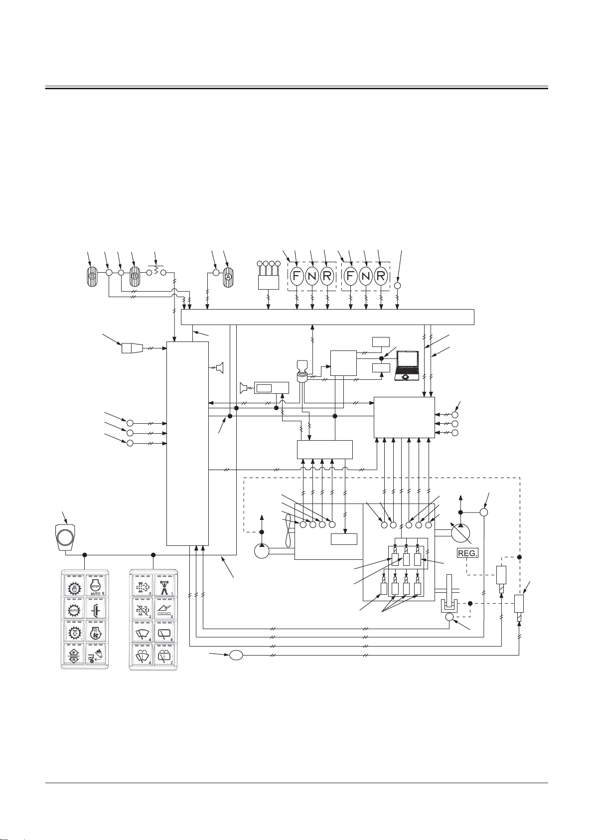
● Manual Speed Shift Control
2
32
33 34 35
1
88
5251 5355 54
36
33 34 35
14
31
69
80
70
13
9 PLCU
47
4
64
11
10
46
50
21
19
17
76
78
7977
1 2 3
26
27
25
24
23
22
6
8
4
79
29
28
30
38
40
41
81
90
91
18
15
16
37
45
56
92
43
44
42
7
TCU
5
ECM
3
MC
● Automatic Speed Shift Control
● Downshift Control
● Rise Run Shift Prohibit Control
● Clutch Cuto Control
● Shift Holding Control
● Torque Converter Lockup Control
Transmission Control System Layout
SECTION 2 SYSTEM
Group 2 Control System
TNFQ-02-02-103-1 ja
TONFQ50-EN-00(28/02/2022)
T2-2-40
 Loading...