

Page 1

-3
• ZX16
-3
• ZX18
PART NO.
EM1NC-EN3-1
-3
• ZX27
-3
HYDRAULIC EXCAVATOR OPERATOR’S MANUAL
Operator's Manual
14
16
-3
-3
URL:http://www.hitachi-c-m.com
PRINTED IN THE NETHERLANDS (ACI) 2009, 12
EM1NC-EN3-1ZX14
18
27
-3
-3
Hydraulic Excavator
Serial No.
ZX14-3 001001 and up
ZX16-3 003001 and up
ZX18-3 005001 and up
ZX27-3 007001 and up
Page 2

INTRODUCTION
Read this manual carefully to learn how to operate and
service your machine correctly. Failure to do so could
result in personal injury or equipment damage.
This standard specification machine can be operated
under the following conditions without being modified.
Atmospheric Temperature: −20°C to 40°C (−4°F to 104°F)
Altitude: 0 m to 1500 m (0 ft to 4900 ft)
In case the machine is used under conditions other than
described above, consult your authorized dealer.
This manual should be considered a permanent part of
your machine and should remain with the machine when
you sell it.
This machine is of metric design. Measurements in this
manual are metric. Use only metric hardware and tools as
specified.
• SI Units (International System of Units) are used in this
manual.
For reference MKS system units and English units are
also indicated in parentheses after the SI units.
Example : 24.5 MPa (250 kgf/cm², 3560 psi)
Right-hand and left-hand sides are determined by
facing in the direction of forward travel.
Write product identification numbers in the Machine
Numbers section. Accurately record all the numbers
to help in tracing the machine should it be stolen.
Your dealer also needs these numbers when you order
parts. If this manual is kept on the machine, also file the
identification numbers in a secure place off the machine.
Warranty is provided as a part of Hitachi’s support
program for customers who operate and maintain their
equipment as described in this manual. The warranty is
explained on the warranty certificate which you should
have received from your dealer.
This warranty provides you the assurance that Hitachi
will back its products where defects appear within the
warranty period. In some circumstances, Hitachi also
provides field improvements, often without charge to the
customer, even if the product is out of warranty.
Should the equipment be abused, or modified to
change its performance beyond the original factory
specifications, the warranty will become void and field
improvements may be denied.
Setting fuel delivery above specifications or otherwise
overpowering machines will result in such action.
Only qualified, experienced operators officially licensed
(according to local law) should be allowed to operate
the machine. Moreover, only officially licensed personnel
should be allowed to inspect and service the machine.
Prior to operating this machine in a country other than
a country of its intended use, it may be necessary to
make modifications to it so that it complies with the local
regulatory standards (including safety standards) and
legal requirements of that particular country. Please do
not export or operate this machine outside of the country
of its intended use until such compliance has been
confirmed.
Please contact Hitachi Construction Machinery Co., Ltd. or
any of our authorized distributor or dealer if you have any
questions concerning compliance.
All information, illustrations and specifications in this manual are based on the latest product information available at the
time of publication. The right is reserved to make changes at any time without notice.
©2009 Hitachi Construction Machinery Co., Ltd.
All rights reserved.
Page 3

INDEX
MACHINE NUMBERS
SAFETY
SAFETY SIGNS
COMPONENTS NAME
OPERATOR’S STATION
BREAK-IN
OPERATING ENGINE
DRIVING MACHINE
OPERATING MACHINE
TRANSPORTING
MAINTENANCE
CONSUMABLE PARTS LIST
MAINTENANCE UNDER SPECIAL ENVIRONMENTAL CONDITIONS
STORAGE
EM1NC-EN3-1
TROUBLESHOOTING
SPECIFICATIONS
OPTIONAL ATTACHMENT AND DEVICE
INDEX
Page 4

Page 5

CONTENTS
MACHINE NUMBERS ........................................................................1
SAFETY ...............................................................................................S-1
Recognize Safety Information ....................................................S-1
Understand Signal Words .............................................................S-1
Follow Safety Instructions ............................................................S-2
Prepare for Emergencies ...............................................................S-2
Wear Protective Clothing..............................................................S-3
Protect Against Noise ....................................................................S-3
Inspect Machine ..............................................................................S-3
Tidy Up Inside Operator’s Space ................................................S-4
Use Handrails and Steps ...............................................................S-4
Never Ride Attachment .................................................................S-4
Adjust Operator’s Seat ...................................................................S-5
Ensure Safety Before Rising from or
Leaving Operator’s Seat ...........................................................S-5
Fasten Your Seat Belt ......................................................................S-5
Move and Operate Machine Safely ...........................................S-6
Operate Only from Operator’s Seat ..........................................S-7
Jump Starting ...................................................................................S-7
Keep Riders Off Machine ..............................................................S-7
Precautions for Operations ..........................................................S-8
Investigate Job Site Beforehand ................................................S-9
Equipment of OPG ....................................................................... S-10
Provide Signals for Jobs Involving
Multiple Machines ..................................................................S-10
Confirm Direction of Machine to be Driven .......................S-10
Drive Machine Safely ................................................................... S-11
Avoid Injury from Rollaway Accidents ..................................S-13
Avoid Injury from Back-over and Swing Accidents ..........S-14
Keep Personnel Clear from Working Area ...........................S-15
Never Position Bucket Over Anyone .....................................S-15
Avoid Undercutting .....................................................................S-15
Avoid Tipping ................................................................................. S-16
Never Undercut a High Bank ....................................................S-16
Dig with Caution ...........................................................................S-17
Operate with Caution ................................................................. S-17
Avoid Power Lines ........................................................................ S-17
Precautions for Lightning .......................................................... S-18
Do Not Use for Craning Operations .......................................S-18
Protect Against Flying Debris ..................................................S-18
Park Machine Safely ..................................................................... S-19
Handle Fluids Safely−Avoid Fires............................................S-19
Safety Transporting .....................................................................S-20
Practice Safe Maintenance ........................................................S-21
Warn Others of Service Work ................................................... S-22
Support Machine Properly ........................................................ S-22
Stay Clear of Moving Parts ........................................................S-23
Prevent Parts from Flying ..........................................................S-23
Store Attachments Safely .......................................................... S-24
Prevent Burns ................................................................................. S-24
Replace Rubber Hoses Periodically ........................................ S-25
Avoid High-pressure Fluids ....................................................... S-25
Prevent Fires ................................................................................... S-26
Evacuating in Case of Fire .......................................................... S-27
Beware of Exhaust Fumes..........................................................S-28
Beware of Asbestos and Silicon Dust and
Other Contamination ............................................................S-28
Precautions for Welding and Grinding .................................S-29
Avoid Heating Near Pressurized Fluid Lines .......................S-29
Avoid Applying Heat to Lines Containing
Flammable Fluids .................................................................... S-29
Remove Paint Before Welding or Heating ........................... S-30
Prevent Battery Explosions ....................................................... S-30
Handle Chemical Products Safely ........................................... S-31
Dispose of Waste Properly ......................................................... S-31
SAFETY SIGNS ............................................................................ S-33
COMPONENTS NAME ................................................................1-1
OPERATOR’S STATION ...............................................................1-3
Pedals, Levers and Monitor Panel ..............................................1-3
Switch Panel .................................................................................1-4
Key Switch ....................................................................................1-5
Monitor Panel ...................................................................................1-6
Alternator Indicator ...................................................................1-6
Fuel Level Indicator ...................................................................1-6
Preheat Indicator ........................................................................1-6
Overheat Indicator ....................................................................1-6
Engine Oil Pressure Indicator.................................................1-7
Hour Meter ...................................................................................1-7
Fuel Gauge (ZX14-3, 16-3, 18-3) ...........................................1-7
Fuel Gauge (ZX27-3) .................................................................1-7
Coolant Temperature Gauge (ZX27-3) ...............................1-7
Coolant Temperature Indicator .............................................1-7
Cab Heater Operation (Cab Equipped Machines) ...............1-8
Heater Operation .......................................................................1-8
Blower Operation .......................................................................1-8
Defroster Operation ..................................................................1-8
Radio (ZX14-3, 16-3, 18-3 Cab Equipped Machines) ..........1-9
AM/FM Radio Operation (Cab Equipped Machine, When
Genuine Radio is Installed) .................................................. 1-10
Part Name and Function ......................................................1-10
Radio Operation ......................................................................1-11
Tuning Procedure ...................................................................1-11
Station Presetting Procedure ..............................................1-12
Deletion of Preset Memory .................................................1-12
Clock Setting Procedure .......................................................1-12
Opening/Closing Cab Front Window (ZX14-3, 16-3, 18-3
Cab Equipped Machines) ..................................................... 1-13
Opening/Closing Cab Front Window (ZX27-3) ..................1-14
Emergency Exit (ZX14-3, 16-3, 18-3 Cab Equipped
Machines) ..................................................................................1-15
Emergency Exit (ZX27-3) ...........................................................1-16
Adjusting Operator’s Seat .........................................................1-17
Seat Fore-Aft Adjustment ....................................................1-17
Tool and Operator’s Manual Box ............................................. 1-18
Seat Belt ........................................................................................... 1-19
Cab Light (Cab Equipped Machines) .....................................1-20
Cab Door Release Lever
(ZX14-3, 16-3, 18-3 Cab Equipped Machines) ..............1-21
Cab Door Release Button (ZX27-3) ........................................1-21
Page 6

CONTENTS
BREAK-IN .........................................................................................2-1
Breaking in New Machine ............................................................2-1
OPERATING ENGINE ...................................................................3-1
Before Starting Engine ..................................................................3-1
Starting Engine ................................................................................3-2
Check Machine After Starting Engine ......................................3-5
Using Booster Battery ....................................................................3-6
Stopping Engine ..............................................................................3-7
DRIVING MACHINE .....................................................................4-1
Travel Levers .....................................................................................4-1
Travel Mode Switch (ZX16-3, 18-3, 27-3).................................4-3
Traveling on Soft Ground .............................................................4-4
Raise One Track Using Boom and Arm ....................................4-4
Towing Machine ..............................................................................4-5
Driving in Water or on Soft Ground ..........................................4-6
Parking and Stopping on Slopes ...............................................4-7
Parking on Slopes ............................................................................4-7
OPERATING MACHINE ...............................................................5-1
Control Lever (ISO Excavator Pattern) ......................................5-1
Boom-Swing Pedal ..........................................................................5-2
Auxiliary Pedal ..................................................................................5-3
Blade Lever ........................................................................................5-4
Precautions for Blade Operation ................................................5-5
Blade and Track Width
Control Lever Operation (ZX18-3) ........................................5-6
Extending / Retracting Blade Width
(ZX18-3) .........................................................................................5-7
Pilot Control Shut-Off Lever ........................................................5-8
Warming Up Operation .............................................................. 5-10
Warming Up in Cold Weather ..................................................5-10
Operating Backhoe ...................................................................... 5-11
Grading Operation .......................................................................5-12
Avoid Driving Bucket Teeth into Ground ............................. 5-12
Avoid Abusive Operation ..........................................................5-12
Avoid Striking with Bucket ........................................................ 5-13
Avoid Excavation Using Upperstructure and/or
Boom Swing Power ................................................................5-13
Use Correct Track Shoe ...............................................................5-13
Avoid Other Than Specified Machine Operations ............5-14
Precautions for Using Bucket Hook .......................................5-15
Boom Cylinder May Hit Blade ..................................................5-15
Avoid Hitting Blade with Bucket .............................................5-16
Avoid Colliding Blade Against Rocks ..................................... 5-16
Avoid Colliding Boom Cylinder with Track ......................... 5-16
Using Rubber Crawler .................................................................5-17
Pipings for Breaker and Crusher ..............................................5-19
Precautions for Breaker Operation ......................................... 5-20
Precautions for Crusher Operation ........................................ 5-23
Precautions for After Operating Machine............................5-24
Emergency Boom Lowering Procedure ...............................5-25
TRANSPORTING ...........................................................................6-1
Transporting by Road ....................................................................6-1
Trailer Loading/Unloading ...........................................................6-1
Loading ...............................................................................................6-2
Securing Machine to Trailer for Transportation ....................6-3
Unloading ..........................................................................................6-4
Lifting Machine with Crane .........................................................6-5
MAINTENANCE .............................................................................7-1
Procedures .........................................................................................7-1
Prepare Machine for Inspection/Maintenance .....................7-2
Opening/Closing Engine Access Covers .................................7-3
Opening/Closing Tank Covers (ZX27-3) ..................................7-4
Opening/Closing Right Side Covers (ZX27-3) .......................7-5
Daily Inspection ...............................................................................7-6
Periodic Replacement of Parts ....................................................7-8
Maintenance Guide ........................................................................7-9
Brand Names of Recommended
Oil and Lubricants ................................................................... 7-12
A. Greasing ......................................................................................7-15
Front Joint Pins (Incl. Swing Post Joint Pins) .................7-15
Bucket and Link Pins .............................................................. 7-18
Blade Pins (ZX27-3).................................................................7-18
Swing Bearing .........................................................................7-19
Swing Internal Gear ...............................................................7-20
Control Lever Universal Joint ..............................................7-20
B. Engine .......................................................................................... 7-21
Engine Oil .................................................................................7-21
Change Engine Oil / Replace Engine Oil Filter .............7-22
C. Transmission ..............................................................................7-24
Travel Reduction Gear ...........................................................7-24
D. Hydraulic System ..................................................................... 7-27
Check Hydraulic Oil Level ...................................................7-28
Drain Hydraulic Oil Tank Sump ..........................................7-29
Change Hydraulic Oil ............................................................7-30
Clean Suction Filter ................................................................7-33
Replace Full Flow Filter ........................................................7-34
Replace Pilot Filter ................................................................. 7-35
Check Hoses and Lines .........................................................7-37
E. Fuel System ................................................................................ 7-44
Check Water Separator .........................................................7-45
Drain Fuel Tank Sump ...........................................................7-46
Replace Fuel Filter ...................................................................7-47
Check Fuel Hoses ....................................................................7-48
F. Air Cleaner ................................................................................... 7-49
Clean Air Cleaner Element ................................................... 7-49
Replace Air Cleaner Element...............................................7-49
G. Cooling System ........................................................................ 7-51
Check Coolant Level .............................................................7-53
Check and Adjust Fan Belt Tension ...................................7-53
Change Coolant ....................................................................... 7-56
Clean Radiator ..........................................................................7-58
Clean Air Conditioner Condenser ..................................... 7-58
H. Electrical System ......................................................................7-59
Battery .........................................................................................7-59
Replacing Fuses ....................................................................... 7-63
I. Miscellaneous ............................................................................. 7-64
Check Bucket Teeth for Looseness and/or Wear ......... 7-64
Replace Bucket.........................................................................7-66
Adjust Track Sag (Rubber Crawler) and Check for
Damage ................................................................................7-67
Page 7

CONTENTS
Replace Rubber Track ............................................................7-69
Check Track Sag (Steel Crawler) (Optional)
(ZX27-3 Only) ...................................................................... 7-71
Check and Replace Seat Belt ............................................... 7-74
Clean Cab Floor (Cab Equipped Machines) ................... 7-75
Check Injection Nozzle .........................................................7-76
Adjust Valve Clearance ..........................................................7-76
Measure Engine Compression Pressure..........................7-76
Check Starter and Alternator .............................................. 7-76
Check Radiator Cap ................................................................ 7-76
Check Crankcase Breather ................................................... 7-76
Check Tightening Torque of Bolts and Nuts ..................7-77
CONSUMABLE PARTS LIST ......................................................8-1
MAINTENANCE UNDER SPECIAL ENVIRONMENTAL
CONDITIONS ..................................................................................9-1
STORAGE ...................................................................................... 10-1
Storing Machine............................................................................10-1
Removing Machine from Storage ..........................................10-2
TROUBLESHOOTING ...............................................................11-1
Impossible to Start Engine ........................................................ 11-1
Engine ............................................................................................... 11-2
Electrical System ........................................................................... 11-5
Mode Selection .............................................................................11-6
Control Levers ................................................................................ 11-7
Hydraulic System ..........................................................................11-7
SPECIFICATIONS .......................................................................12-1
Specifications ZX14-3 ................................................................
Working Ranges ZX14-3 ........................................................... 12-2
Bucket Types and Applications ZX14-3 ...............................12-3
Specifications ZX16-3 ................................................................ 12-4
Working Ranges ZX16-3 ........................................................... 12-5
Bucket Types and Applications ZX16-3 ..............................12-6
Specifications ZX18-3 ................................................................ 12-7
Working Ranges ZX18-3 ........................................................... 12-8
Bucket Types and Applications ZX18-3 ...............................12-9
Specifications ZX27-3 ..............................................................12-10
Working Ranges ZX27-3 .........................................................12-11
Bucket Types and Applications ZX27-3 .............................12-12
Noise Level Results (2000/14/CE, art. VI) ............................12-13
Vibration Level .............................................................................12-13
Special Specification .................................................................12-14
OPTIONAL ATTACHMENT AND DEVICE ..........................13-1
Ignition Block System (Optional) ............................................ 13-1
INDEX ............................................................................................. 14-1
12-1
Page 8

CONTENTS
MEMO
..................................................................................................................................................................................................
..................................................................................................................................................................................................
..................................................................................................................................................................................................
..................................................................................................................................................................................................
..................................................................................................................................................................................................
..................................................................................................................................................................................................
..................................................................................................................................................................................................
..................................................................................................................................................................................................
..................................................................................................................................................................................................
..................................................................................................................................................................................................
..................................................................................................................................................................................................
..................................................................................................................................................................................................
..................................................................................................................................................................................................
..................................................................................................................................................................................................
..................................................................................................................................................................................................
..................................................................................................................................................................................................
..................................................................................................................................................................................................
..................................................................................................................................................................................................
..................................................................................................................................................................................................
..................................................................................................................................................................................................
..................................................................................................................................................................................................
..................................................................................................................................................................................................
..................................................................................................................................................................................................
..................................................................................................................................................................................................
..................................................................................................................................................................................................
..................................................................................................................................................................................................
..................................................................................................................................................................................................
..................................................................................................................................................................................................
..................................................................................................................................................................................................
..................................................................................................................................................................................................
..................................................................................................................................................................................................
..................................................................................................................................................................................................
..................................................................................................................................................................................................
..................................................................................................................................................................................................
..................................................................................................................................................................................................
..................................................................................................................................................................................................
..................................................................................................................................................................................................
Page 9

MACHINE NUMBERS
The manufacturing Nos. explained in this group is the
individual number (serial No.) given to each machine and
hydraulic components. These numbers are requested when
inquiring any information on the machine and/or components.
Fill these serial Nos. in the blank spaces in this group to
immediately make them available upon request.
Machine
MODEL/TYPE:________________
PRODUCT IDENTIFICATION NUMBER:
___________________________
Product Identification Number
PRODUCT IDENTIFICATION NUMBER:
___________________________
NOTE:
f
*HCM1NC00X00001001*
Marks to indicate the start
and end of the PIN
ZX14-3, 16-3, 18-3
ZX27-3
M1NC-00-001
M1N7-00-001
PRODUCT IDENTIFICATION
NUMBER (PIN)
ZX14-3, 16-3, 18-3
ZX27-3
M1NC-00-002
M1N7-00-002
1
Page 10

Engine
TYPE:
MFG. NO.:
MACHINE NUMBERS
Travel Motor
TYPE:
MFG. NO.:
ZX14-3, 16-3, 18-3
ZX27-3
M1NC-00-003
M1NC-00-015
Swing Motor
TYPE:
MFG. NO.:
M1NC-00-004
M1NC-00-005
2
Page 11

Hydraulic Pump
TYPE:
MFG. NO.:
MACHINE NUMBERS
ZX14-3, 16-3, 18-3
ZX27-3
M1NC-00-006
M1NC-00-016
3
Page 12

MACHINE NUMBERS
MEMO
..................................................................................................................................................................................................
..................................................................................................................................................................................................
..................................................................................................................................................................................................
..................................................................................................................................................................................................
..................................................................................................................................................................................................
..................................................................................................................................................................................................
..................................................................................................................................................................................................
..................................................................................................................................................................................................
..................................................................................................................................................................................................
..................................................................................................................................................................................................
..................................................................................................................................................................................................
..................................................................................................................................................................................................
..................................................................................................................................................................................................
..................................................................................................................................................................................................
..................................................................................................................................................................................................
..................................................................................................................................................................................................
..................................................................................................................................................................................................
..................................................................................................................................................................................................
..................................................................................................................................................................................................
..................................................................................................................................................................................................
..................................................................................................................................................................................................
..................................................................................................................................................................................................
..................................................................................................................................................................................................
..................................................................................................................................................................................................
..................................................................................................................................................................................................
..................................................................................................................................................................................................
..................................................................................................................................................................................................
..................................................................................................................................................................................................
..................................................................................................................................................................................................
..................................................................................................................................................................................................
..................................................................................................................................................................................................
..................................................................................................................................................................................................
..................................................................................................................................................................................................
..................................................................................................................................................................................................
..................................................................................................................................................................................................
..................................................................................................................................................................................................
..................................................................................................................................................................................................
4
Page 13

SAFETY
Recognize Safety Information
• These are the SAFETY ALERT SYMBOLS.
• When you see these symbols on your machine or in this
manual, be alert to the potential for personal injury.
• Follow recommended precautions and safe operating
practices.
Understand Signal Words
• On machine safety signs, signal words designating the
degree or level of hazard - DANGER, WARNING, or CAUTION
- are used with the safety alert symbol.
• DANGER indicates an imminently hazardous situation
which, if not avoided, will result in death or serious injury.
• WARNING indicates a potentially hazardous situation
which, if not avoided, could result in death or serious
injury.
• CAUTION indicates a potentially hazardous situation
which, if not avoided, may result in minor or moderate
injury.
• DANGER or WARNING safety signs are located near
specific hazards. General precautions are listed on
CAUTION safety signs.
• Some safety signs do not use any of the designated signal
words above after the safety alert symbol are occasionally
used on this machine.
SA-688
• To avoid confusing machine protection with personal
safety messages, a signal word IMPORTANT indicates a
situation which, if not avoided, could result in damage to
the machine.
• fNOTE indicates an additional explanation for an element
of information.
SA-1223
S-1
Page 14

SAFETY
Follow Safety Instructions
• Carefully read and follow all safety signs on the machine as
well as all safety messages in this manual.
• Safety signs must be installed, maintained and replaced if
damaged.
• If a safety sign or this manual is damaged or missing,
order a replacement from your authorized dealer in the
same way you order other replacement parts (be sure to
state machine model and serial number when ordering).
• Allow only properly trained, qualified, authorized personnel
to operate the machine.
• Learn how to correctly operate and service the machine.
• Keep your machine in proper working condition.
• Always operate the machine within the specification.
• Unauthorized modifications of the machine may impair
the functions and/or safety and affect machine life and
the warranty will become void.
• The safety messages in this SAFETY chapter are intended
to illustrate basic safety procedures of machines. However
it is impossible for these safety messages to cover every
possible hazardous situation you may encounter. If you
have any questions concerning safety, you should first
consult your supervisor and/or your authorized dealer
before operating or performing maintenance work on the
machine.
SA-003
Prepare for Emergencies
• Be prepared if a fire starts or if an accident occurs.
• Keep a first aid kit and fire extinguisher on hand.
• Thoroughly read and understand the label attached on
the fire extinguisher to use it properly.
• To ensure that a fire extinguisher can be always used
when necessary, check and service the fire extinguisher
at the recommended intervals as specified in the fire
extinguisher manual.
• Establish emergency procedure guidelines to cope with
fires and accidents.
• Keep emergency numbers for doctors, ambulance
service, hospital, and fire department posted near your
telephone.
SA-437
S-2
Page 15

SAFETY
Wear Protective Clothing
• Wear close fitting clothing and safety equipment
appropriate to the job.
You may need:
A hard hat
Safety shoes
Safety glasses, goggles, or face shield
Heavy gloves
Hearing protection
Reflective clothing
Wet weather gear
Respirator or filter mask.
Be sure to wear the correct equipment and clothing for the
job. Do not take any chances.
• Avoid wearing loose clothing, jewelry, or other items that
can catch on control levers or other parts of the machine.
• Operating equipment safely requires the full attention of
the operator.
• Do not wear radio or music headphones while operating
the machine.
SA-438
Protect Against Noise
• Prolonged exposure to loud noise can cause impairment or
loss of hearing.
• Wear a suitable hearing protective device such as
earmuffs or earplugs to protect against objectionable or
uncomfortably loud noises.
Inspect Machine
• If any abnormality is found, be sure to repair it immediately
before operating the machine.
• In the walk-around inspection, be sure to cover all points
described in the “Before Starting Engine” section in the
operator’s manual.
SA-434
S-3
SA-435
Page 16

SAFETY
Tidy Up Inside Operator’s Space
• Always keep inside the operator’s space clean by observing
instructions below, to prevent any personal accidents from
occurring.
• Remove mud and/or oily material from the shoe soles
before entering the operator’s space. If pedals are
operated without removing mud or oily matter, the foot
may slip off the pedal, possibly creating a hazardous
situation.
• Do not leave parts and/or tools around the operator’s
seat.
• Avoid storing transparent bottles in the cab. Do not
attach any transparent type window decorations on
the windowpanes as they may focus sunlight, possibly
starting a fire.
• Do not wear radio or music headphones and do not use a
cell phone while traveling or operating the machine.
• Never allow hazardous materials such as combustible
and/or explosive material in the operator’s space.
• Do not leave cigarette lighters in the cab. If the
temperature in the cab increases, the lighter may
explode.
Use Handrails and Steps
• Falling is one of the major causes of personal injury.
• When you get on and off the machine, always use the
crawler instead of the step for safety. Also get on and off
from the position of the crawler that can secure your feet
space enough.
• When you get on and off the machine, always face the
machine.
• Maintain a three-point contact with the steps and
handrails.
• Do not use any controls as handholds.
• Never jump on or off the machine. Never mount or
dismount a moving machine.
• In case adhered slippery material such as oil, grease,
or mud is present on steps, handrails, or platforms,
thoroughly remove such material.
Never Ride Attachment
• Never allow anyone to ride attachments or the load. This is
an extremely dangerous practice.
SA-439
S-4
Page 17

SAFETY
Adjust Operator’s Seat
• A poorly adjusted seat for either the operator or the
work at hand may quickly fatigue the operator leading to
misoperation of the machine.
• The seat should be adjusted whenever the operator for
the machine changes.
• The operator should be able to fully depress the pedals
and to correctly operate the control levers with his back
firmly against the seat back.
• If not, readjust the seat forward or backward, and check
again.
Ensure Safety Before Rising from or Leaving
Operator’s Seat
• Before rising from the operator’s seat to open/close either
side window or to adjust the seat position, be sure to first
lower the front attachment to the ground and then move
the pilot control shut-off lever to the LOCK position. Failure
to do so may allow the machine to unexpectedly move
when a body part unintentionally comes into contact with a
control lever, possibly resulting in serious personal injury or
death.
• Before leaving the machine, be sure to first lower the
front attachment to the ground and then move the pilot
control shut-off lever to the LOCK position. Turn the key
switch OFF to stop the engine.
• Before leaving the machine, close all windows, doors, and
access covers and lock them up.
SA-378
Fasten Your Seat Belt
• If the machine should overturn, the operator may become
injured and/or thrown from the cab. Additionally the
operator may be crushed by the overturning machine,
resulting in serious injury or death.
• Be sure to remain seated with the seat belt securely
fastened whenever operating the machine.
• Prior to operating the machine, thoroughly examine
webbing, buckle and attaching hardware. If any item is
damaged or worn, replace the seat belt or component
before operating the machine. Replace the seat belt at
least once every 3 years regardless of appearance.
S-5
SA-237
Page 18

SAFETY
Move and Operate Machine Safely
• Always be aware that there is a potential danger around the
machine while operating the machine.
• Take extra care not to run over bystanders. Confirm the
location of bystanders before moving, swinging, or
operating the machine.
• Always keep the travel alarm and horn in working
condition (if equipped).
• Before starting to move or operate the machine, sound
the travel alarm and horn to alert bystanders.
• Use a signal person when moving, swinging, or operating
the machine in congested areas. Locate the signal person
so that the operator can always witness the signal person.
• Coordinate the meanings of all safety signs, hand signals
and marks before starting the machine. Appoint a person
who is responsible to make a signal and/or guidance.
• Never allow any persons or obstacles to enter the
machine operation areas.
• Use appropriate illumination. Check that all lights are
operable before operating the machine. If any faulty
illumination is present, immediately repair it.
SA-1291
S-6
Page 19

SAFETY
Operate Only from Operator’s Seat
• Inappropriate engine starting procedures may cause the
machine to runaway, possibly resulting in serious injury or
death.
• Start the engine only when seated in the operator’s seat.
• NEVER start the engine while standing on the tracks or on
ground.
• Do not start engine by shorting across starter terminals.
A hazardous situation may be created and/or possible
damage to the machine may result.
• Before starting the engine, confirm that all control levers
are in neutral.
Jump Starting
• Failure to follow correct jump starting procedures could
result in a battery explosion or a runaway machine.
• If the engine must be jump started, be sure to follow the
instructions shown in the “OPERATING ENGINE” chapter.
• The operator must be seated in the operator’s seat so
that the machine will be under control when the engine
starts. Jump starting is a two-person operation.
• Never use a frozen battery.
• Failure to follow correct jump starting procedures could
result in a battery explosion or a runaway machine.
SA-444
Keep Riders Off Machine
• Riders on machine are subject to injury such as being struck
by foreign objects and being thrown off the machine.
• Riders also obstruct the operator’s view, resulting in the
machine being operated in an unsafe manner.
• Only the operator is allowed on the machine. Keep riders
off.
SA-032
SA-1292
S-7
Page 20

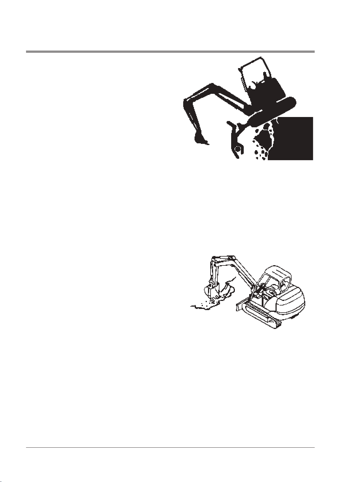
Precautions for Operations
WARNING: Thoroughly make certain safety at the
d
work site before starting operations. Especially
always observe the following points.
• Be sure to install the overhead cab guard before
operating the machine in areas where the
possibility of falling stones or debris exists.
• If operation on soft ground is required, sufficiently
reinforce the ground beforehand.
• Be sure to wear close fitting clothing and required safety
items, such as a helmet, when operating the machine.
• Keep all bystanders and unnecessary objects out of and
away from the machine working areas. Always beware of
the surroundings while operating the machine. Take care
not to allow the rear part of the upperstructure to come
into contact with objects when swinging the machine in
a small area.
• When loading a dump truck, bring the bucket from the
rear side of the dump truck to avoid moving the bucket
over the dump truck cab or over any co-workers.
SAFETY
M586-12-012
S-8
Page 21
SAFETY
Investigate Job Site Beforehand
• When working at the edge of an excavation or on a road
shoulder, the machine could tip over due to collapse of the
ground, possibly resulting in serious injury or death.
• Investigate the configuration and ground conditions of
the job site beforehand to prevent the machine from
falling and to prevent the ground, stockpiles, or banks
from collapsing.
• Make a work plan. Use machines appropriate to the work
and job site.
• Reinforce ground, edges, and road shoulders as
necessary. Keep the machine well back from the edges of
excavations and road shoulders.
• When working on an incline or on a road shoulder,
employ a signal person as required.
• Never allow bystanders to enter the working area such as
swing radius or traveling range.
• When the footing is weak, reinforce the ground before
starting work.
• When working on frozen ground, be extremely alert. As
ambient temperatures rise, footing may become loose
and slippery.
• When operating the machine near open flame, sparks,
and/or dead grass, a fire may easily break out. Use special
care not to cause a fire.
• Make sure the work site ground has sufficient strength to
firmly support the machine. When working close to an
excavation or on road shoulders, operate the machine
with the tracks positioned perpendicular to the cliff face
with travel motors at the rear and with the blade at the
front, so that the machine can more easily evacuate if the
cliff face collapses.
• If working at the bottom of a cliff or on a high bank is
required, be sure to investigate the area first and confirm
that no danger of the cliff or bank collapsing exists. If any
possibility of cliff or bank collapsing exists, do not work in
that area.
• Soft ground may collapse when operating the machine
on it, possibly causing the machine to tip over. When
working on soft ground is required, be sure to reinforce
the ground first using large pieces of steel plates strong
enough and firm to easily support the machine.
• Note that there is always a possibility of machine tipping
over when working on rough terrain or on slopes. Prevent
machine tipping over from occurring. Operate the
machine slowly to ensure safe operation.
SA-1293
M586-05-021
S-9
Page 22

Equipment of OPG
• In case the machine is operated in areas where the
possibility of falling stones or debris exists, equip genuine
Hitachi OPG guard. Contact your nearest Hitachi dealer for
installation method of the OPG guard. Depending on the
specifications applied to your machine, modification of the
machine to meet ROPS standards will be possible.
• To maintain unimpaired operator protection and
manufacture's protective structure.
• Damaged ROPS, OPG guard must be replaced, not
repaired or revised.
• Any alternation to the ROPS or OPG guard must be
approved by the manufacturer.
ROPS : Roll Over Protective Structure
OPG : Operator Protective Guard
Provide Signals for Jobs Involving Multiple
Machines
SAFETY
• In case more than one machine is operated in the same
job site, accidental collision between machines may cause
serious injury or death.
• For jobs involving multiple machines, provide signals
commonly known by all personnel involved. Also, appoint
a signal person to coordinate the job site. Make sure that all
personnel obey the signal person’s directions.
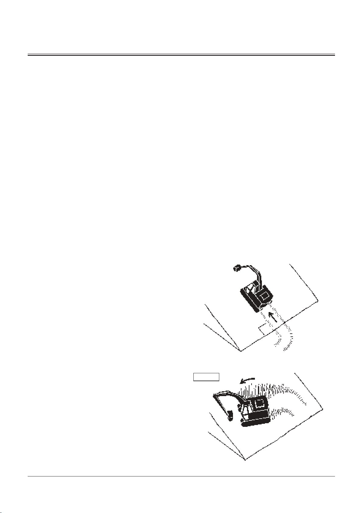
Confirm Direction of Machine to be Driven
• Incorrect travel pedal/lever operation may result in serious
injury death.
• Before driving the machine, confirm the position of the
undercarriage in relation to the operator’s position.
• If the travel motors are located towards the front of the
cab, the machine will move in the reverse direction when
travel pedals/levers are operated.
SA-481
SA-1294
S-10
Page 23
SAFETY
Drive Machine Safely
• Use a signal person when traveling the machine along road
shoulders or in congested areas.
• Driving the machine in the incorrect direction may result in
serious injury or death and/or severe damage to property.
• Before driving the machine, always confirm that the travel
pedals/levers direction corresponds to the direction you
wish to drive.
• Be sure to detour around any obstructions.
• Avoid traveling over obstructions. Soil, fragments of rocks,
and/or metal pieces may scatter around the machine. Do
not allow personnel to stay around the machine while
traveling.
• Driving on a slope may cause the machine to slip or
overturn, possibly resulting in serious injury or death.
• Never attempt to ascend or descend (B) degrees or
steeper slopes.
B : ZX14-3, 16-3, 18-3 : 25˚
ZX27-3 : 30˚
• Be sure to fasten the seat belt.
• When driving up or down a slope, keep the bucket facing
the direction of travel, approximately 200 to 300 mm (8 to
12 in) (A) above the ground.
• If machine starts to skid or becomes unstable,
immediately lower the bucket to the ground and stop.
• Driving across the face of a slope or steering on a
slope may cause the machine to skid or turnover. If
the direction must be changed, move the machine to
level ground, then, change the direction to ensure safe
operation.
• Avoid swinging the upperstructure on slopes. Never
attempt to swing the upperstructure downhill. The
machine may tip over. If swinging uphill is unavoidable,
carefully operate the upperstructure and boom at slow
speed.
• If the engine stalls on a slope, immediately lower the
bucket to the ground. Return the control levers to neutral.
Then, restart the engine.
• Be sure to thoroughly warm up the machine before
ascending steep slopes. If hydraulic oil has not warmed
up sufficiently, sufficient performance may not be
obtained.
A
SA-1295
A
SA-1296
SA-441
WRONG
S-11
SA-590
Page 24

SAFETY
• Traveling down a slope in the fast mode requires a longer
time to stop the machine.
When traveling down a slope, place engine control lever
(1) in the TURTLE position.
• Use a signal person when moving, swinging or operating
the machine in congested areas. Coordinate hand signals
before starting the machine.
• Before moving machine, determine which way to move
travel pedals/levers for the direction you want to go.
When the travel motors are in the rear, pushing down
on the front of the travel pedals or pushing the levers
forward moves the machine forward, towards the idlers.
• Select a travel route that is as flat as possible. Steer the
machine as straight as possible, making small gradual
changes in direction.
• Before traveling on them, check the strengths of bridges
and road shoulders, and reinforce if necessary.
• Do not make contact with electric wires or bridges.
• When crossing a river, measure the depth of the river
using the bucket, and cross slowly. Do not cross the river
when the depth of the river is deeper than the upper
edge of the upper roller.
• When traveling on rough terrain, reduce engine speed.
Select slow travel speed. Slower speed will reduce
possible damage to the machine.
• Avoid operations that may damage the track and
undercarriage components.
• During freezing weather, always clean snow and ice from
track shoes before driving the machine on snowy and/or
frozen roads, or loading and unloading the machine for
transportation, to prevent the machine from slipping.
1
M1NC-00-007
Travel Motor
M104-05-008
S-12
SA-673
M586-05-002
Page 25

SAFETY
Avoid Injury from Rollaway Accidents
• Death or serious injury may result if you attempt to mount
or try to bodily stop a moving machine.
• Park the machine in compliance with the safe parking
procedures described on page S-19 to prevent the machine
from running away.
• Block both tracks and lower the bucket to the ground,
thrust the bucket teeth into the ground if you must park
on a grade.
• Park at a reasonable distance from other machines.
SA-1297
S-13
Page 26

SAFETY
Avoid Injury from Back-over and Swing
Accidents
• If any person is present near the machine when backing or
swinging the upperstructure, the machine may hit or run
over that person, resulting in serious injury or death.
To avoid back-over and swing accidents:
• Always look around BEFORE YOU BACK UP AND SWING
THE MACHINE. BE SURE THAT ALL BYSTANDERS ARE
CLEAR.
• Keep the travel alarm in working condition (if equipped).
ALWAYS BE ALERT FOR BYSTANDERS MOVING INTO THE
WORK AREA. USE THE HORN OR OTHER SIGNAL TO WARN
BYSTANDERS BEFORE MOVING MACHINE.
• USE A SIGNAL PERSON WHEN BACKING UP IF YOUR VIEW
IS OBSTRUCTED. ALWAYS KEEP THE SIGNAL PERSON IN
VIEW.
Use hand signals, which conform to your local regulations,
when work conditions require a signal person.
• No machine motions shall be made unless signals are
clearly understood by both signalman and operator.
• Learn the meanings of all flags, signs, and markings used
on the job and confirm who has the responsibility for
signaling.
• Keep windows, mirrors, and lights clean and in good
condition.
• Dust, heavy rain, fog, etc., can reduce visibility. As visibility
decreases, reduce speed and use proper lighting.
• Read and understand all operating instructions in the
operator’s manual.
SA-383
SA-384
S-14
Page 27
SAFETY
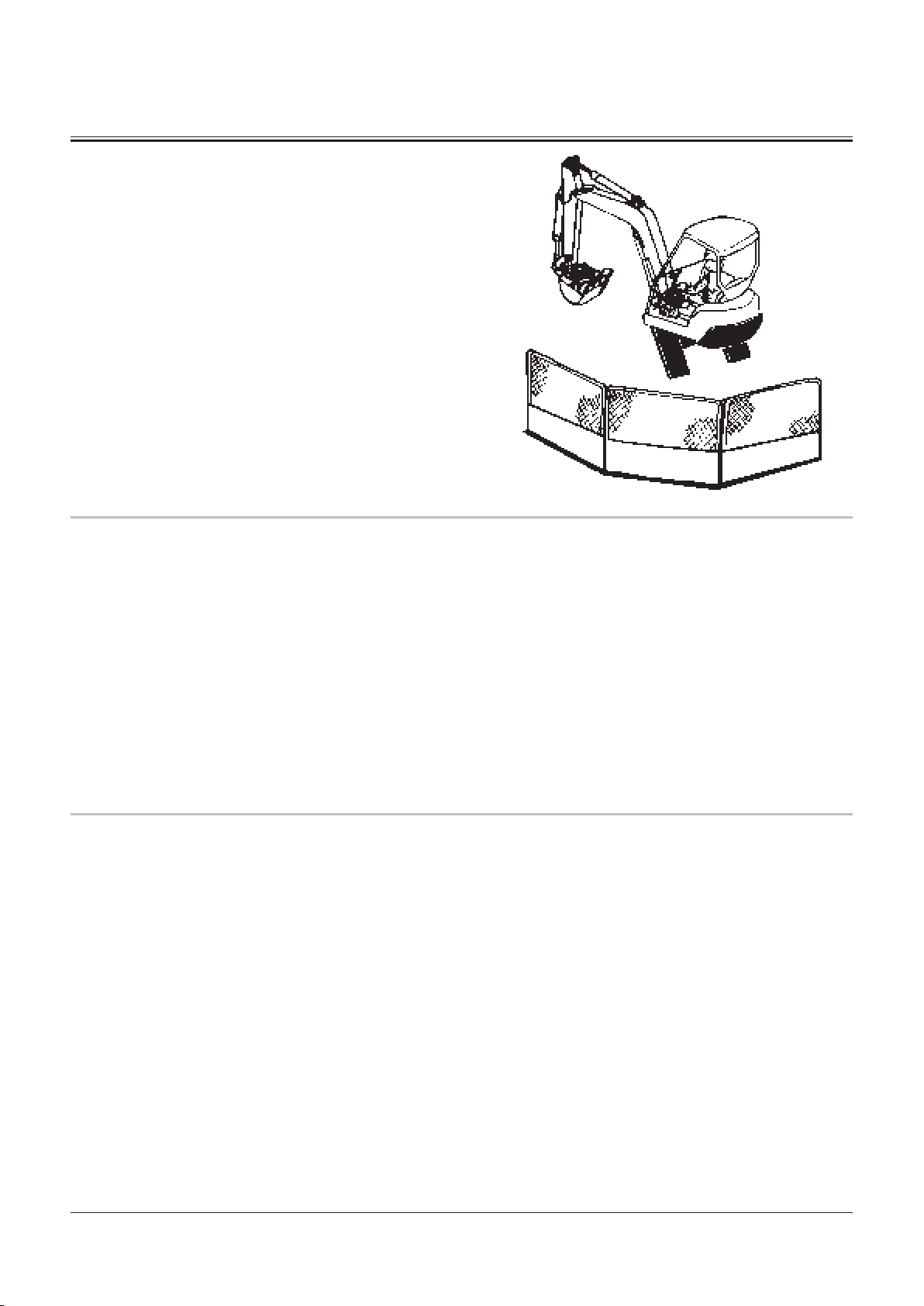
Keep Personnel Clear from Working Area
• If a person is present near the operating machine, the
person may come into contact with the swinging front
attachment or counterweight and/or may be crushed
against an other object, resulting in serious injury or death.
• Before operating the machine, set up barriers to the
sides and rear area of the bucket swing radius to prevent
anyone from entering the work area.
• Make sure that no personnel other than the signal person
or no obstacles are present in the working area before
operating the machine.
Never Position Bucket Over Anyone
• Never lift, move, or swing bucket above anyone or a truck
cab.
Serious injury or machine damage may result due to bucket
load spill or due to collision with the bucket.
• Never allow the bucket to pass over anyone to avoid
personal injury or death.
SA-667
Avoid Undercutting
• In order to retreat from the edge of an excavation if the
footing should collapse, always position the undercarriage
perpendicular to the edge of the excavation with the travel
motors at the rear.
• If the footing starts to collapse and if retreat is not
possible, do not raise the front attachment in a panic.
Lowering the front attachment may be safer in most
cases.
SA-668
SA-1300
S-15
Page 28

SAFETY
Avoid Tipping
• The danger of tipping is always present when operating on
a grade, possibly resulting in serious injury or death.
To avoid tipping:
• Be extra careful before operating on a grade.
• Prepare machine operating area flat.
• Keep the bucket low to the ground and close to the
machine.
• Reduce operating speeds to avoid tipping or slipping.
• Avoid changing direction when traveling on grades.
• NEVER attempt to travel across a grade steeper than 15
degrees if crossing the grade is unavoidable.
• Reduce swing speed as necessary when swinging loads.
• Be careful when working on frozen ground.
• Temperature increases will cause the ground to become
soft and make ground travel unstable.
Never Undercut a High Bank
• The edges could collapse or a land slide could occur causing
serious injury or death.
SA-1301
SA-1302
S-16
Page 29
SAFETY
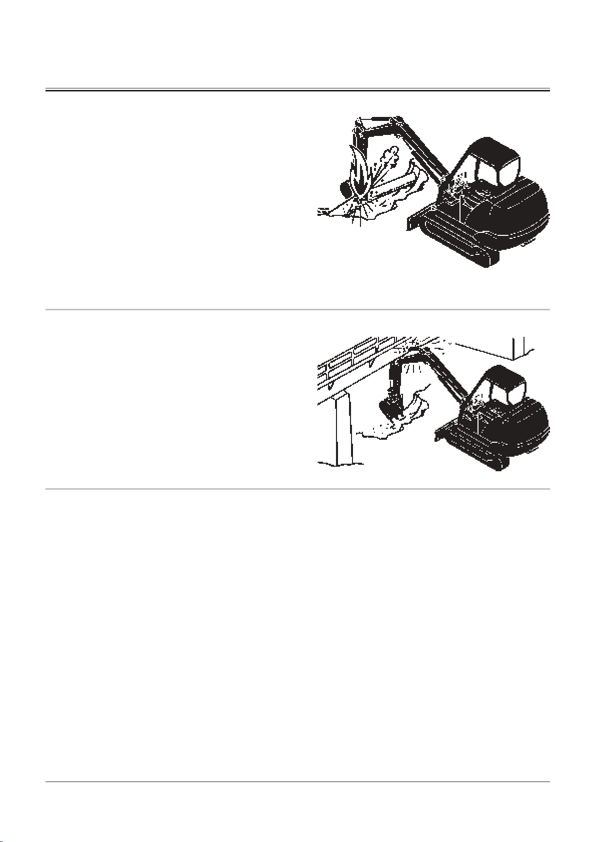
Dig with Caution
• Accidental severing of underground cables or gas lines may
cause an explosion and/or fire, possibly resulting in serious
injury or death.
• Before digging check the location of cables, gas lines, and
water lines.
• Keep the minimum distance required, by law, from cables,
gas lines, and water lines.
• If a fiber optic cable should be accidentally severed, do
not look into the end. Doing so may result in serious eye
injury.
• Contact your local “diggers hot line” if available in your
area, and/or the utility companies directly.
Have them mark all underground utilities.
Operate with Caution
• If the front attachment or any other part of the machine hits
against an overhead obstacle, such as a bridge, both the
machine and the overhead obstacle will be damaged, and
personal injury may result as well.
• Take care to avoid hitting overhead obstacles with the
boom or arm.
SA-672
Avoid Power Lines
• Serious injury or death can result if the machine or front
attachments are not kept a safe distance from electric lines.
• When operating near an electric line, NEVER move any
part of the machine or load closer than 3 m (10 ft) plus
twice the line insulator length.
• Check and comply with any local regulations that may
apply.
• Wet ground will expand the area that could cause any
person on it to be affected by electric shock. Keep all
bystanders or co-workers away from the site.
SA-673
SA-1305
S-17
Page 30

SAFETY
Precautions for Lightning
• The machine is vulnerable to lightning strikes.
• In the event of an electrical storm, immediately stop
operation, and lower the bucket to the ground. Evacuate
to a safe place far away from the machine.
• After the electrical storm has passed, check all of the
machine safety devices for any failure. If any failed
safety devices are found, operate the machine only after
repairing them.
Do Not Use for Craning Operations
• NEVER use the machine for craning operations. If the
machine is used for craning operations, the machine may
tip over and/or lifted load may fall, possibly resulting in
serious injury or death.
• This machine has been exclusively designed to engage in
excavation and loading works.
• This machine is not equipped with any of the necessary
safety devices that could allow the machine to be used for
craning operation.
SA-1805
Protect Against Flying Debris
• If flying debris such as soil, rock fragments or metal pieces
hit eyes or any other part of the body, serious injury may
result.
• Guard against such injuries when working in a job site
where possibility of flying pieces of metal or debris exist,
or when removing or installing pins using a hammer;
wear goggles or safety glasses.
• Keep bystanders away from the working area before
striking any object.
S-18
SA-014
SA-432
Page 31

SAFETY
Park Machine Safely
• Unless the machine is correctly parked, any hazardous
situations such as running away of the machine or damage
by vandalism may result, causing the machine to operate
unsafely when the engine is restarted. Follow instructions
described below when parking the machine.
• Park the machine on solid level surface to prevent the
machine from running away.
• Lower the bucket and/or blade to the ground.
• Pull the lock lever to the LOCK position.
• Run the engine at slow idle speed without load for 5
minutes.
• Turn key switch to OFF to stop engine. Remove the key
from the key switch.
• Before leaving the machine, close all windows, roof vent,
and cab door. Lock all access doors and compartments.
Handle Fluids Safely−Avoid Fires
• Handle fuel with care; it is highly flammable. If fuel ignites,
an explosion and/or a fire may occur, possibly resulting in
serious injury or death.
• Do not refuel the machine while smoking or when near
open flame or sparks.
• Always stop the engine before refueling the machine.
• Fill the fuel tank outdoors.
SA-1306
• All fuels, most lubricants, and some coolants are flammable.
• Store flammable fluids well away from fire hazards.
• Do not incinerate or puncture pressurized containers.
• Do not store oily rags; they can ignite and burn
spontaneously.
SA-018
SA-019
S-19
Page 32

SAFETY
Safety Transporting
• The danger of tipping is present when loading/unloading
the machine onto/from a truck or trailer bed.
• Be sure to observe local regulations when transporting
the machine on public roads.
• Provide an appropriate truck or trailer for transporting the
machine.
• Be sure to have a signal person.
• Take the following precautions when loading/unloading
the machine.
1. Select firm level ground.
2. Be sure to use a loading dock or ramp strong enough to
support the machine weight.
3. Ramps must be sufficient in width, length, and strength.
Be sure that the incline of the ramp is less than 15
degrees.
4. Loading docks must be sufficient in width and strength
to support the machine and have a gradient of less than
15 degrees.
5. Slowly drive the machine.
SA-1307
6. Avoid steering while driving up or down the ramp as it
is extremely dangerous. If steering is unavoidable, first
move back to the ground or flatbed, change traveling
direction, and begin to drive again.
7. The top end of the ramp where it meets the flatbed is a
sudden bump. Take care when traveling over it.
8. Wedge the front and rear of the tracks. Securely fasten
the machine to the trailer bed with chain or cables.
9. Do not operate any levers besides the travel levers when
driving up or down the ramp.
10. Prevent possible injury from machine tipping while the
upperstructure is rotating.
11. Keep the arm tucked under and rotate the
upperstructure slowly for best stability.
Refer to “transporting” chapter in this manual for details.
S-20
Page 33

SAFETY
Practice Safe Maintenance
• Inspection/maintenance work may produce hazardous
situations by contacting and/or accessing a part of body
to a moving, high pressure, and/or high temperature part
of the machine. To avoid serious personal injury or death,
follow the instructions described below.
• Thoroughly coordinate the working procedures to be
taken hereafter with the co-workers before beginning
work such as inspecting/servicing the machine, or
replacing the attachment .
• Safely park the machine in accordance with the
instructions for “Park Machine Safely.”
• Keep the work area clean and orderly.
• Attach a “DO NOT OPERATE” tag in an easy-to-see location
such as on a door or a control lever.
• If moisture permeates into the electrical system,
malfunction and/or erroneous movement of the machine
may result. Do not clean sensors, cable connectors, and
the cab inside using water and/or steam.
• Wait to begin to work until the engine and hydraulic oil
temperatures have cooled down to the safety range.
• In case inspection/maintenance must be performed with
the engine running, be sure to appoint an overseer.
• Never lubricate or service the machine while moving it.
• Repair the cracked windowpane before servicing the
machine. Failure to do so may cause personal injury.
• When raising the machine above the ground using the
front attachment function, maintain the angle between
the boom and the arm in the range of 90 to 110°. Never
allow anyone to enter under the machine raised with the
front attachment function.
• In case working under the machine raised above the
ground is unavoidably required, securely hold the
machine with stays or blocks strong enough to support
the machine weight.
• Never work under the raised bucket.
• Keep all parts in good condition and properly installed.
• Always use the specified tools correctly.
• Always use a clean tool.
• Fix any damage found immediately. Replace worn or
broken parts.
• Remove any buildup of grease, oil, or debris.
• When cleaning parts, use a non-combustible cleaning
solvent. Never use an inflammable fluid such as diesel
fuel, or gasoline.
SA-028
90 to 110°
M1M7-04-006
SA-527
S-21
Page 34

SAFETY
• Disconnect battery ground cable (−) before making
adjustments to electrical systems or before welding on
the machine.
• Sufficiently illuminate the work site. Use a maintenance
work light when working under or inside the machine.
• Always use a work light protected with a guard. In case
the light bulb is broken, spilled fuel, oil, antifreeze fluid,
or window washer fluid may catch fire.
Warn Others of Service Work
• Unexpected machine movement can cause serious injury.
• Before performing any work on the machine, attach a “Do
Not Operate” tag in an easy-to-see place such as on the
cab door or control lever.
• Never attempt to operate the machine with a “Do Not
Operate” tag attached.
• Make it a rule for the inspection/service person to hold
the engine start key during inspection/service work.
SA-037
Support Machine Properly
• Never attempt to work on the machine without securing
the machine first.
• Always lower the attachment to the ground before you
work on the machine.
• If you must work on a lifted machine or attachment,
securely support the machine or attachment with stays
or blocks strong enough to support the machine and/or
attachment weight.
SS2045102
SA-527
S-22
Page 35

SAFETY
Stay Clear of Moving Parts
• Contact with moving parts can cause serious injury or death
due to amputation or entanglement.
• To prevent accidents, care should be taken to ensure that
hands, feet, clothing, jewelry and hair do not become
entangled when working around rotating parts.
Prevent Parts from Flying
• Grease in the track adjuster is under high pressure.
Failure to follow the precautions below may result in serious
injury, blindness, or death.
• Do not attempt to remove GREASE FITTINGS or VALVE
ASSEMBLIES.
• As pieces of parts may fly off, be sure to keep body and
face away from the valve.
SA-026
• Travel reduction gears are under pressure.
• As pieces of parts may fly off, be sure to keep body and
face away from AIR RELEASE PLUG to avoid injury.
• GEAR OIL is hot. Wait for gear oil to cool, then gradually
loosen the air release plug to release pressure.
SA-344
S-23
Page 36

SAFETY
Store Attachments Safely
• Stored attachments such as buckets, hydraulic hammers,
and blades can fall and cause serious injury or death.
• Securely store attachments and implements to prevent
falling accidents.
• Keep children and bystanders away from storage areas.
Prevent Burns
Hot spraying fluids:
• After operation, engine coolant is hot and under pressure.
Hot water or steam is contained in the engine, radiator and
heater lines.
Skin contact with escaping hot water or steam can cause
severe burns.
• To prevent possible injury from hot spraying water, stop
the engine. Begin to work after the engine and radiator
are sufficiently cooled.
• DO NOT remove the radiator cap until the engine is cool.
When opening, turn the cap slowly to the stop. Allow all
pressure to be released before removing the cap.
• The hydraulic oil tank is pressurized. Again, be sure to
release all pressure by slowly removing the cap.
SA-034
SA-039
Hot fluids and surfaces:
• Engine oil, gear oil and hydraulic oil also becomes hot
during operation.
The engine, hoses, lines and other parts become hot as well.
• Wait for the oil and components to cool before starting
any maintenance or inspection work.
SA-225
S-24
Page 37

SAFETY
Replace Rubber Hoses Periodically
• Rubber hoses that contain flammable fluids such as
hydraulic oil or fuel under pressure may break due to aging,
fatigue, and abrasion. It is very difficult to gauge the extent
of deterioration due to aging, fatigue, and abrasion of
rubber hoses by visual inspection alone.
• Periodically replace the rubber hoses. (Refer to the
Periodical Replacement Parts section.)
• Failure to periodically replace rubber hoses may cause a fire,
fluid injection into skin, or the front attachment to fall on a
person nearby, which may result in severe burns, gangrene,
or otherwise serious injury or death.
Avoid High-pressure Fluids
• Fluids such as diesel fuel or hydraulic oil under pressure can
penetrate the skin or eyes causing serious injury, blindness
or death.
• Avoid this hazard by relieving pressure before
disconnecting hydraulic or other lines. Make sure that all
connectors are completely connected before applying
pressure.
• Search for leaks with a piece of cardboard; take care to
protect hands and body from high-pressure fluids. Wear a
face shield or goggles for eye protection.
• If an accident occurs, see a doctor familiar with this
type of injury immediately. Any fluid injected into the
skin must be surgically removed within a few hours, or
gangrene may result.
SA-019
SA-031
S-25
SA-292
SA-044
Page 38

SAFETY
Prevent Fires
Check for Oil Leaks:
• Fuel, hydraulic oil and lubricant leaks can lead to fires,
possibly resulting in personal injury or death.
• Check for missing or loose clamps, kinked hoses, lines or
hoses that rub against each other, damage to the oilcooler, and loose oil-cooler flange bolts, for oil leaks.
• Tighten, repair or replace any missing, loose or damaged
clamps, lines, hoses, oil-cooler and oil-cooler flange bolts.
• Do not bend or strike high-pressure lines.
• Never install bent or damaged lines, pipes or hoses.
Check for Shorts:
• Short circuits can cause fires.
• Clean and tighten all electrical connections.
• Check before each shift or after eight (8) to ten (10) hours
operation for loose, kinked, hardened or frayed electrical
cables and wires.
• Check before each shift or after eight (8) to ten (10) hours
operation for missing or damaged terminal caps.
• DO NOT OPERATE MACHINE if cable or wires are loose,
kinked, etc.
SA-019
Precautions for Handling Flammables
• Spilled fuel and oil, and trash, grease, debris, accumulated
coal dust, and other flammables may cause fires.
• Prevent fires by inspecting and cleaning the machine
daily, and by removing spilled or accumulated
flammables immediately.
• Do not store flammable fluid near open flames.
• Do not burn or crush a pressurized container.
• Do not store oily cloths. They are liable to catch fire.
• Do not wind easy-to-absorb-oil asbestos or glass wool
around high-temperature parts such as a muffler or
exhaust pipe.
S-26
Page 39

SAFETY
Check Heat Shield Covers around Engine Compartment
• If the engine compartment heat shield cover becomes
broken or lost, fire may break out.
• If the engine compartment heat shield cover becomes
broken or lost, repair or replace it before operating the
machine.
Check Key Switch:
• If fire breaks out, failure to stop the engine will escalate the
fire, hampering fire fighting.
• Always check key switch function before operating the
machine every day:
1) Start the engine and run it at slow idle.
2) Turn the key switch to the OFF position to confirm that
the engine has stopped.
If any abnormalities are found, be sure to repair them before
operating the machine.
Evacuating in Case of Fire
• If fire breaks out during machine operation, evacuate the
machine in the following way:
• Stop the engine by turning the key switch to the OFF
position.
• Use a fire extinguisher if there is time.
• Exit the machine using handrails and/or steps.
• In an emergency, if the cab door or front or rear window can
not be opened, break the front or rear window panes with
the emergency evacuation hammer to escape from the cab.
Refer to the explanation pages on the Emergency Exit.
SA-393
SS-1510
S-27
Page 40

SAFETY
Beware of Exhaust Fumes
• Prevent asphyxiation. Engine exhaust fumes can cause
sickness or death.
• If you must operate the machine in a building, be sure
there is adequate ventilation. Either use an exhaust pipe
extension to remove the exhaust fumes or open doors
and windows to bring enough outside air into the area.
Beware of Asbestos and Silicon Dust and Other
Contamination
• Take care not to inhale dust produced in the work site.
Inhalation of asbestos fibers may be the cause of lung
cancer.
Inhalation of silicon dust and other contamination may
cause sickness.
• Depending on the work site conditions, the risk
of inhaling asbestos fiber, silicon dust or other
contamination may exist.
Spray water to prevent asbestos, silicon dust or other
contamination from airborne. Do not use compressed air.
• When operating the machine in a work site where
asbestos, silicon dust or other contamination might be
present, be sure to operate the machine from the upwind
side and wear a mask rated to prevent the inhalation of
asbestos, silicon dust or other contamination.
• Keep bystanders out of the work site during operation.
• Asbestos might be present in imitation parts. Use only
genuine Hitachi Parts.
SA-016
SA-029
S-28
Page 41

SAFETY
Precautions for Welding and Grinding
• Welding may generate gas and/or small fires.
• Be sure to perform welding in a well ventilated and
prepared area. Store flammable objects in a safe place
before starting welding.
• Only qualified personnel should perform welding. Never
allow an unqualified person to perform welding.
• Grinding on the machine may create a fire hazard. Store
flammable objects in a safe place before starting grinding.
• After finishing welding and grinding, recheck that there are
no abnormalities such as the area surrounding the welded
area still smoldering.
Avoid Heating Near Pressurized Fluid Lines
• Flammable spray can be generated by heating near
pressurized fluid lines, resulting in severe burns to yourself
and bystanders.
• Do not heat by welding, soldering, or using a torch near
pressurized fluid lines or other flammable materials.
• Pressurized lines can be accidentally cut when heat goes
beyond the immediate flame area. Install temporary
fire resistant guards to protect hoses or other materials
before engaging in welding, soldering, etc.
SA-818
Avoid Applying Heat to Lines Containing
Flammable Fluids
• Do not weld or flame cut pipes or tubes that contain
flammable fluids.
• Remove flammable fluids thoroughly with nonflammable
solvent before welding or flame cutting pipes or tubes
that contained flammable fluids.
SA-030
S-29
Page 42

SAFETY
Remove Paint Before Welding or Heating
• Hazardous fumes can be generated when paint is heated by
welding, soldering, or using a torch. If inhaled, these fumes
may cause sickness.
• Remove paint before welding or heating.
• Avoid potentially toxic fumes and dust.
• Do all such work outside or in a well-ventilated area.
Dispose of paint and solvent properly.
• Allow fumes to disperse at least 15 minutes after welding
or heating.
• Use attention to the following points when removing
paint.
1. If you sand or grind paint, avoid breathing the dust
which is created.
Wear an approved respirator.
2. If you use solvent or paint stripper, remove stripper with
soap and water before welding.
3. Remove solvent or paint stripper containers and other
flammable material from area.
SA-029
Prevent Battery Explosions
• Battery gas can explode.
• Keep sparks, lighted matches, and flame away from the
top of battery.
• Never check battery charge by placing a metal object
across the posts. Use a voltmeter or hydrometer.
• Do not charge a frozen battery; it may explode. Warm the
battery to 16 °C (60 °F) first.
• Do not continue to use or charge the battery when the
electrolyte level is lower than specified. Explosion of the
battery may result.
• When a terminal become loose, it may induce sparks.
Securely tighten all terminals.
• Battery electrolyte is poisonous. If the battery should
explode battery electrolyte may be splashed into eyes,
possibly resulting in blindness. If electrolyte is splashed into
eyes, flush your eyes continuously with water for about 15
minutes. Seek medical attention immediately.
• Be sure to wear eye protection when checking electrolyte
specific gravity.
SA-032
S-30
Page 43

SAFETY
Handle Chemical Products Safely
• Direct exposure to hazardous chemicals can cause serious
injury. Potentially hazardous chemicals used with your
machine include such items as lubricants, electrolyte,
coolants, paints, and adhesives.
• A Material Safety Data Sheet (MSDS) provides specific
details on chemical products: physical and health
hazards, safety procedures, and emergency response
techniques.
• Check the MSDS before you start any job using a
hazardous chemical. Then follow the correct procedures
and use recommended equipment.
• See your authorized dealer for MSDS.
Dispose of Waste Properly
• Improperly disposing of waste can threaten the
environment and ecology. Potentially harmful waste used
with HITACHI equipment includes such items as oil, fuel,
coolant, brake fluid, filters, and battery.
• When draining fluid, use a leakproof container with a
capacity larger than the drained fluid volume to receive it.
• Do not pour waste onto the ground, down a drain, or into
any water source.
• Inquire on the proper way to dispose of harmful waste
such as oil, fuel, coolant, brake fluid, filters, and battery
from your local environmental or recycling center.
SA-309
SA-226
S-31
Page 44

SAFETY
MEMO
..................................................................................................................................................................................................
..................................................................................................................................................................................................
..................................................................................................................................................................................................
..................................................................................................................................................................................................
..................................................................................................................................................................................................
..................................................................................................................................................................................................
..................................................................................................................................................................................................
..................................................................................................................................................................................................
..................................................................................................................................................................................................
..................................................................................................................................................................................................
..................................................................................................................................................................................................
..................................................................................................................................................................................................
..................................................................................................................................................................................................
..................................................................................................................................................................................................
..................................................................................................................................................................................................
..................................................................................................................................................................................................
..................................................................................................................................................................................................
..................................................................................................................................................................................................
..................................................................................................................................................................................................
..................................................................................................................................................................................................
..................................................................................................................................................................................................
..................................................................................................................................................................................................
..................................................................................................................................................................................................
..................................................................................................................................................................................................
..................................................................................................................................................................................................
..................................................................................................................................................................................................
..................................................................................................................................................................................................
..................................................................................................................................................................................................
..................................................................................................................................................................................................
..................................................................................................................................................................................................
..................................................................................................................................................................................................
..................................................................................................................................................................................................
..................................................................................................................................................................................................
..................................................................................................................................................................................................
..................................................................................................................................................................................................
..................................................................................................................................................................................................
..................................................................................................................................................................................................
S-32
Page 45

SAFETY SIGNS
All safety signs and their locations affixed on the machine are
illustrated in this group. Make sure of the contents described
in the safety signs through reading actual ones affixed on
the machine to ensure safe machine operation. Always keep
the safety signs clean. In case a safety sign is broken or lost,
immediately, obtain a new replacement and affix it again in
position on the machine. Use the part No. indicated under the
right corner of each safety sign illustration when ordering it at
your authorized dealer.
SS4420332
• Always read the Operator’s Manual before operating,
servicing, disassembling, assembling, and transporting the
machine.
ZX14-3, 16-3, 18-3
M1NC-00-008
S-33
ZX27-3
M1NC-00-017
Page 46

SAFETY SIGNS
SS4420333
• If the parked machine is unexpectedly moved, serious injury
or death due to crushing may result. Be sure to lower the
front attachment to the ground, lock the control levers,
and remove the engine key before leaving the machine
unattended.
ZX14-3, 16-3, 18-3
M1NC-00-008
• Electrocution is possible if the machine is operated too
close to power lines. Always keep a safe distance from
power lines.
SS-1613
ZX27-3
ZX14-3, 16-3, 18-3
M1NC-00-017
M1NC-00-008
S-34
ZX27-3
M1NC-00-017
Page 47

• Stand clear of the equipment. If
knocked over by the equipment,
serious injury may result.
SAFETY SIGNS
• Hot coolant or oil may spout if the
radiator or hydraulic oil cap is removed
while the machine temperature is
still high, possibly causing a burn.
Wait until the machine has cooled to
remove the cap.
SS-1702
SS-1703
ZX14-3, 16-3, 18-3
SS-1494
M1NC-00-009
S-35
ZX27-3
M1NC-00-018
Page 48

• Sign indicates the hazard of rotating
parts, such as fan, etc that could
cause injury by being caught. Turn it
off completely before inspection and
maintenance.
SAFETY SIGNS
SS-1704
ZX14-3, 16-3, 18-3
M1NC-00-009
• Sign indicates the hazard of rotating
parts, such as belt, etc that could
cause injury by being caught. Turn it
off completely before inspection and
maintenance.
SS-1705
ZX27-3
ZX14-3, 16-3, 18-3
M1NC-00-019
M1NC-00-009
S-36
ZX27-3
M1NC-00-019
Page 49

SAFETY SIGNS
• Serious injury may result if the plug flies off the track
adjuster. Read the Operator’s Manual before loosening
the track, and adjust the track sag following the correct
procedure.
• Possible severe burns. Do not touch
the engine components while they are
hot.
SS-1710
SS-1495
SS4392289
ZX14-3, 16-3, 18-3
ZX27-3
M1NC-00-009
M1NC-00-020
S-37
Page 50

• Hot coolant or oil may spout if the
radiator or hydraulic oil cap is removed
while the machine temperature is
still high, possibly causing a burn.
Wait until the machine has cooled to
remove the cap.
SAFETY SIGNS
SS-1703
SS-1714
ZX14-3, 16-3, 18-3
ZX27-3
M1NC-00-010
M1NC-00-018
• Personnel in the swing radius may be crushed by the
upperstructure when the machine swings. Stand clear of
the swing radius.
S-38
ZX14-3, 16-3, 18-3
ZX27-3
M1NC-00-011
M1NC-00-021
Page 51

• Personal injury may result if the stored
front window slips off. Always securely
lock the window in the stored position
(on the cab equipped machine).
SAFETY SIGNS
• Sign indicates the hazard of rotating parts, such as fan,
etc that could cause injury by being caught. Turn it off
completely before inspection and maintenance.
SS-1706
SS-1719
ZX14-3, 16-3, 18-3
SS-2641
M1NC-00-011
S-39
ZX27-3
M1NC-00-021
Page 52

SAFETY SIGNS
ROPS/TOPS/TOP GUARD Canopy and Cab
• To maintain unimpaired operator protection and
manufacture’s protective structure.
• Damaged Roll Over Protective Structure (ROPS), Tip Over
Protective Structure (TOPS), Operator Protective Guard
Top Guard (TOP GUARD) must be replaced, not repaired
or revised.
• Any alternation to the ROPS or TOPS or TOP GUARD
canopy and cab must be approved by the manufacturer.
ZX14-3
ZX14-3
SS3115731
SS3116740
ZX16-3, 18-3
SS3117290
ZX16-3, 18-3
SS3117293
ROPS Canopy
ZX14-3, 16-3, 18-3
ROPS Cab
ZX14-3, 16-3, 18-3
M1NC-01-013
M1MS-00-004
ZX14-3
SS3116078
ZX16-3, 18-3
SS3117804
S-40
TOPS Canopy
ZX14-3, 16-3, 18-3
M1NC-00-014
Page 53

SAFETY SIGNS
ZX27-3
SS3118030
ROPS Cab
ZX27-3
M1NC-00-022
S-41
Page 54

SAFETY SIGNS
MEMO
..................................................................................................................................................................................................
..................................................................................................................................................................................................
..................................................................................................................................................................................................
..................................................................................................................................................................................................
..................................................................................................................................................................................................
..................................................................................................................................................................................................
..................................................................................................................................................................................................
..................................................................................................................................................................................................
..................................................................................................................................................................................................
..................................................................................................................................................................................................
..................................................................................................................................................................................................
..................................................................................................................................................................................................
..................................................................................................................................................................................................
..................................................................................................................................................................................................
..................................................................................................................................................................................................
..................................................................................................................................................................................................
..................................................................................................................................................................................................
..................................................................................................................................................................................................
..................................................................................................................................................................................................
..................................................................................................................................................................................................
..................................................................................................................................................................................................
..................................................................................................................................................................................................
..................................................................................................................................................................................................
..................................................................................................................................................................................................
..................................................................................................................................................................................................
..................................................................................................................................................................................................
..................................................................................................................................................................................................
..................................................................................................................................................................................................
..................................................................................................................................................................................................
..................................................................................................................................................................................................
..................................................................................................................................................................................................
..................................................................................................................................................................................................
..................................................................................................................................................................................................
..................................................................................................................................................................................................
..................................................................................................................................................................................................
..................................................................................................................................................................................................
..................................................................................................................................................................................................
S-42
Page 55

Components Name
ZX14-3, 16-3, 18-3
COMPONENTS NAME
1- Counterweight
2- Canopy
3- Boom
4- Work Light
5- Arm Cylinder
6- Bucket Cylinder
7- Arm
8- Bucket
9- Boom Cylinder
10- Blade
11- Blade Cylinder
12- Front Idler
1
13- Boom-Swing Cylinder
14- Track Shoe
15- Track Frame
16- Travel Device
2
43
5
9
816 15 14 13 12 11 10
7 6
M1NC-01-001
1-1
Page 56

ZX27-3
1- Counterweight
2- Cab
3- Boom
4- Work Light
5- Arm Cylinder
6- Bucket Cylinder
7- Arm
8- Bucket
9- Boom Cylinder
10- Blade
11- Blade Cylinder
12- Front Idler
7
13- Boom-Swing Cylinder
COMPONENTS NAME
2
5
34
1
9
13
14- Track Shoe
15- Track Frame
16- Travel Device
6
8
16
10 11 12
14
15
M1NC-01-019
1-2
Page 57

OPERATOR’S STATION
Pedals, Levers and Monitor Panel
1- Left Control Lever
2- Pilot Control Shut-Off Lever
3- Attachment Pedal
4- Left Travel Lever
5- Right Travel Lever
6- Right Control Lever / Horn Switch
7- Boom-Swing Pedal
8- Blade Lever
9- Key Switch
10- Engine Control Lever
11- Monitor Panel
12- Operator’s Seat
13- Fuse Box
14- Pilot Control Shut-Off Lever (Canopy Spec Only)
NOTE: The typical machine model is illustrated to the right.
f
Some portions may differ on other models.
1 2 3 4 5 6 7
12
M1NC-01-002
14
8
9
10
11
13
ZX14-3, 16-3, 18-3
ZX27-3
M1NC-01-003
13
M1NC-01-020
1-3
Page 58

OPERATOR'S STATION
Switch Panel
5- Work Light Switch
Press the switch (5) to turn work lights (10) located on
the boom ON, and External electrical outlet (11) on.
6- Track-width Control Switch (ZX18-3)
7- Travel Mode Indicator (ZX16-3, 18-3, 27-3)
8- Heater Control Panel (Cab equipped machine)
9- Wiper Switch (Cab equipped machine)
Three-operation positions are provided on this switch.
OFF: Both the wiper and washer do not operate.
Center: The wiper operates.
WASHER: The washer operates together with the wiper.
11
9 8
7
6
5
ZX14-3, 16-3, 18-3
9
5
8
M1NC-01-004
ZX14-3, 16-3, 18-3
11
ZX27-3
10
M1NC-01-024
M1NC-01-025
ZX27-3
ZX27-3
M1NC-01-021
7
M1NC-01-022
10
ZX27-3
M1M7-01-025
1-4
ZX14-3, 16-3, 18-3
M1NC-01-001
Page 59

OPERATOR'S STATION
Key Switch
1- OFF (Engine OFF)
2- ON (ZX14-3, 16-3, 18-3 : Engine ON, ZX27-3 : Engine ON,
Preheat)
3- START (Engine Start)
4- HEAT (Engine Preheat) (ZX14-3, 16-3, 18-3)
3
2
1
4
M1M7-01-007
1-5
Page 60

OPERATOR'S STATION
Monitor Panel
1- Alternator Indicator
2- Fuel Level Indicator
3- Preheat Indicator
4- Overheat Indicator
5- Engine Oil Pressure Indicator
6- Hour Meter
7- Fuel Gauge
8- Coolant Temperature Indicator
9- Coolant Temperature Gauge (ZX27-3)
10- Travel Mode Indicator (ZX27-3)
8
4 5 7
9
8
7
6
162 3
M1NC-01-005
ZX14-3, 16-3, 18-3
1
2
10
4
5
3
Alternator Indicator
The red indicator will light when low alternator output is
present.
Check the electrical system such as the alternator and/or
battery system.
Fuel Level Indicator
When the fuel level indicator lights while the machine is
operating on level ground, the remaining fuel amount in
the fuel tank is 3.6 L (1.0 US gal). Refill the fuel as soon as
possible.
Preheat Indicator
When the key switch is turned to the HEAT position, orange
indicator will light. Light will turn off after approx. 3 seconds
have passed.
Overheat Indicator
If the coolant temperature rises extremely high, this
indicator lights. If the red light comes ON, the buzzer sounds
at the same time.
Immediately stop machine operation and reduce engine
speed to the slow idle speed to lower the coolant
temperature.
ZX27-3
M1NC-01-022
M178-01-038
M178-01-034
M178-01-041
M178-01-036
1-6
Page 61

OPERATOR'S STATION
Engine Oil Pressure Indicator
The red indicator will light when the engine oil pressure is
low. If the red indicator comes ON, the engine oil pressure
warning buzzer will sound at the same time. Immediately
stop the engine. Check the engine oil pressure system and
the oil level for any abnormality.
Hour Meter
Total (accumulated) machine operation hours counted since
the machine started working, are displayed in the unit of
HOUR (h). One digit after the decimal point indicates the
tenths of an hour (6 minutes).
Fuel Gauge (ZX14-3, 16-3, 18-3)
The gauge segment position indicates the fuel level. Refill
the fuel before only the E-marked segment comes ON.
M178-01-037
M1NC-01-006
M1NC-01-007
Fuel Gauge (ZX27-3)
The gauge needle position indicates the fuel level.
When the needle reaches the E-point in the white range, the
remaining fuel is approximately 10 liters.
Coolant Temperature Gauge (ZX27-3)
The gauge needle position indicates the engine coolant
temperature. Coolant temperature is normal when the
needle stays in white zone while operating.
Coolant Temperature Indicator
M1MW-01-007
M1MW-01-008
When the key switch is turned to the ON position, the
indicator will light when the engine coolant temperature is
low.
1-7
M1NC-01-008
Page 62

OPERATOR'S STATION
Cab Heater Operation (Cab Equipped Machines)
Heater Operation
Turn heater cock (1) in the engine compartment
counterclockwise. Adjust air flow by turning heater adjust
knob (2) located at the right- rear in the operator’s station.
Blower Operation
Turn heater cock (1) in the engine compartment clockwise
to close it. Adjust air flow following the same method as
mentioned in the Heater Operation.
Defroster Operation
Adjust air flow by operating heater adjust knob (2). Remove
clouding on the window pane by directing air flow from air
vent (3) and (4) toward the window pane.
1
ZX14-3, 16-3, 18-3
1
M1NC-01-009
ZX27-3
4
3
ZX14-3, 16-3, 18-3
3
2
M1NC-01-023
2
M1NC-01-004
1-8
4
ZX27-3
M1NC-01-021
Page 63

OPERATOR'S STATION
Radio (ZX14-3, 16-3, 18-3 Cab Equipped
Machines)
1- Radio/Clock
1
M1MS-01-014
1-9
Page 64

OPERATOR'S STATION
AM/FM Radio Operation (Cab Equipped Machine,
When Genuine Radio is Installed)
Part Name and Function
1- Power Switch/Volume Control Knob
Rotate the knob to the right to supply electric power (a click
sound will be heard when the unit is turned ON). Rotate the
knob further to turn up the volume. Rotate the knob in the
reverse direction to turn down the volume and the unit OFF.
2- Tone Control Knob
Rotate the knob to the right to intensify the treble.
Rotate the knob to the left to reduce the treble.
3- Display
Time, receiving radio wave frequency, or operation mode
is displayed.
4- Clock Button
Press this button to display the time. Repress this button
to display the receiving radio wave frequency.
2
1 3 8 75 4
6 9
M1M7-01-011
5- Auto-Store/ Scan Preset Button (AST)
Press this button to receive the preset frequency station
for every 5 seconds sequentially. While you receive
the station you wish to listen to, press this button
again to receive the station under normal state (scan is
interrupted). Press and hold this button for 2 seconds to
automatically store the station.
6- Station Preset Buttons (1 to 6)
One FM and MW (AM) station per button can be preset
using these respective buttons.
7- Seek Button
Press this button to automatically seek the next
receivable station. When a station is received, the autoseeking function is deactivated.
8- Band Button
Select FM or MW (AM) by pressing this button. The
display indicates the receiving station frequency.
9- Tuning Button
Tap the TUNE
TUNE ∨ button to decrease the frequency. Tap and hold
the button to change the frequency continuously.
∧ button to increase the frequency. Tap the
1-10
Page 65

OPERATOR'S STATION
Radio Operation
1. Turn the key switch to the ACC or ON position to switch
the radio ON.
2. Select either MW (AM) or FM by operating the band
button.
3. Select the station desired to listen using the preset or
tuning button.
4. Adjust the volume and tone according to your
preference.
5. When turning the radio OFF, rotate the VOL knob to the
left until a click sound is heard.
Tuning Procedure
1. Tap the TUNE ∧ button to increase the frequency. Tap the
TUNE ∨ button to decrease the frequency. Tap and hold
the button to change the frequency continuously.
2. Automatic Tuning
M1M7-01-011
Press this button to automatically move the frequency
up and to seek a receivable station. When a station is
received, the auto-seeking function is deactivated so
that the received frequency station is tuned in.
1-11
Page 66

OPERATOR'S STATION
Station Presetting Procedure
1. Select MW (AM) or FM by pressing BAND button (8).
Select a station by pressing either TUNE button (9) or
SEEK button (7).
2. Continuously press one of PRESET button (6) by which
you desire to preset the station for more than 2 seconds.
When presetting is complete, the preset button No. is
indicated on the display.
3. Repeat the above same procedure steps (1) and (2) to
preset other stations with other PRESET buttons (6).
NOTE: After presetting is complete, if the preset button is
f
pressed again and held for more than 2 seconds, the
preset station is changed.
• Auto-Storing
Press and hold the AST button for more than 2 seconds
with the radio switch ON, preset buttons (1 to 6)
automatically search receivable frequency stations in the
selected frequency band (AM or FM) and memorize each
station in one button.
NOTE: When auto-store operation is made, the preciously
f
memorized stations are deleted. If it is difficult to
set the memory of the desired station to the desired
button, conduct preset operation.
2
1 3 8 75 4
2
1 3 8 75 4
6 9
6 9
M1M7-01-011
M1M7-01-011
• Preset Scanning
Press and release the AST button in 2 seconds with the
radio switch ON, preset station frequencies are received
one by one for 5 seconds. Press the button again to
resume normal radio operation.
Deletion of Preset Memory
If the battery power is disconnected such as when the
machine is serviced or the radio is removed, the preset
memory in the preset buttons will be deleted. Repeat the
preset operation again.
Clock Setting Procedure
In case the frequency is indicated on the display, press the
CLOCK button to display the time.
While pressing the CLOCK button, press TUNE ∧ M button
to change the minute display. While pressing the CLOCK
button, press TUNE ∨ H button to change the hour display.
Release the CLOCK button to resume the original mode.
While pressing CLOCK button
Minute is adjusted
Hour is adjusted
M1M7-01-012
1-12
Page 67

OPERATOR'S STATION
Opening/Closing Cab Front Window (ZX14-3, 163, 18-3 Cab Equipped Machines)
CAUTION:
d
• When closing the front window, slowly lower the
window. Be alert not to pinch your fingers.
• After opening the front window, check that both
side lock levers are securely engaged in the
window frame.
Opening:
1. Hold the handles (1) (in two places) on the front window
and disengage lock lever (2).
2. Hold the handles (in two places) on the front window
frame and raise the window until the lock lever (2)
engages with the window frame.
Closing:
3. When closing the front window, follow the same steps 1
and 2 above in the reverse order.
1
M1NC-01-010
M1NC-01-011
1-13
22
M1NC-01-012
Page 68

OPERATOR'S STATION
Opening/Closing Cab Front Window (ZX27-3)
CAUTION: The front window comes down forcefully.
d
Close the front window only when sitting on the
operator’s seat. Guide the front window down slowly.
Opening:
1. Push in lock switches (1) to unlock the front window.
2. Pull the front window up and back until slide lock
switches (1) fall into boss holes and Lock.
Closing:
3. To close the front window, perform procedures shown in
steps (1) to (2) in reverse. These are:
a. Push in lock switches (1), to unlock the front window
b. Pull the front window down slowly
c. Be sure that the front window is locked
1
M1LN-01-007
1-14
Page 69

OPERATOR'S STATION
Emergency Exit (ZX14-3, 16-3, 18-3 Cab
Equipped Machines)
If the operator’s cab door can not be opened in an emergency,
escape in the following methods.
1. When required to escape from the cab when the door
is difficult or impossible to open in an emergency, open
the front window.
NOTE: Refer to the descriptions in Opening/Closing Cab
f
Front Window for the opening method of the front
window.
CAUTION: Take care not to be injured with pieces of
d
broken glass.
2. In case opening the front window is impossible, break
the front window glass with emergency evacuation
hammer (1) provided on the rear side in the cab to
escape through the broken window.
1
M1MS-01-015
3. If the front window is not available for escaping, break
the rear window glass with emergency evacuation
hammer (1). Then, escape through the broken window.
NOTE: Emergency exit decal is affixed on the front and rear
f
window.
Front
Rear
M1MW-01-015
M1MS-01-016
1-15
Page 70

OPERATOR'S STATION
Emergency Exit (ZX27-3)
If the operator’s cab door should not open in an emergency,
escape in the following methods:
1. Open the front window. Escape through the window.
NOTE: Refer to the descriptions in Opening/Closing Cab
f
Front Window for the opening method of the front
window.
CAUTION: Be sure to wear safety glasses before
d
breaking the window glass.
2. If the front window is difficult to open, break the front
window glass using emergency evacuation tool (1).
Then, escape through the broken window.
3. If the front window is not available for escaping, break
the rear window glass using emergency evacuation tool
(1). Then, escape through the broken window.
NOTE: The emergency exit decals are affixed to the front and
f
rear windows.
1
M1LS-01-008
Front Window
Rear Window
SS-2470
M1LS-01-008
1-16
Page 71

OPERATOR'S STATION
Adjusting Operator’s Seat
Seat Fore-Aft Adjustment
Operate seat fore-aft slide lever (1). Seat fore-aft position
can be adjusted at the interval of 10 mm (ZX14-3, 16-3, 18-3:
14 steps to 140 mm in total /ZX27-3: 12 steps to 120 mm in
total).
1
M1NC-01-013
1-17
Page 72

OPERATOR'S STATION
Tool and Operator’s Manual Box
• ZX14-3, 16-3, 18-3
Tool and operator’s manual box (2) is located under the
operator’s seat.
• ZX27-3
Tool box (2) and operator’s manual box (3) are located under
the operator’s seat, under the floor mat and behind the
backrest of the operator’s seat respectively.
ZX14-3, 16-3, 18-3
ZX27-3
2
2
M1NC-01-013
M1NC-07-035
3
1-18
ZX27-3
M1M7-01-018
Page 73

OPERATOR'S STATION
Seat Belt
WARNING: Be sure to use the seat belt when
d
operating the machine.
Before operating the machine, be sure to examine
seat belt (1), buckle (2), or attaching hardware.
Replace seat belt (1), buckle (2), or attaching
hardware if they are damaged, or worn.
Replace seat belt (1) every three years, regardless of
appearance.
1. Confirm that seat belt (1) is not twisted and securely
insert the end of seat belt (1) into buckle (2).
Lightly pull on the belt to confirm that the buckle latches
securely.
2. Adjust tightness of the seat belt (1) so that the belt is
snug but comfortable.
3. Push button (3) on buckle (2) to unfasten seat belt (1).
12
M1NC-01-014
1
M1NC-01-015
12
3
M1NC-01-016
1-19
Page 74

OPERATOR'S STATION
Cab Light (Cab Equipped Machines)
Move cab light switch (4) to turn the cab light ON or OFF.
(The cab light comes ON only when the key switch is turned
ON.)
4
ZX14-3, 16-3, 18-3
ZX27-3
M1MS-01-017
4
M585-01-021
1-20
Page 75

OPERATOR'S STATION
Cab Door Release Lever (ZX14-3, 16-3, 18-3 Cab
Equipped Machines)
CAUTION: Open the cab door all the way until the
d
latch on the side of the cab securely locks.
To unlock the door, push down on lever (5) located on the left
side of the operator’s seat.
5
Cab Door Release Button (ZX27-3)
CAUTION: Open the cab door all the way until the
d
latch on the side of the cab securely locks.
Pull button (3) to unlock the door.
ZX14-3, 16-3, 18-3
M1M0-01-006
3
1-21
ZX27-3
M1LN-01-004
Page 76

OPERATOR'S STATION
MEMO
..................................................................................................................................................................................................
..................................................................................................................................................................................................
..................................................................................................................................................................................................
..................................................................................................................................................................................................
..................................................................................................................................................................................................
..................................................................................................................................................................................................
..................................................................................................................................................................................................
..................................................................................................................................................................................................
..................................................................................................................................................................................................
..................................................................................................................................................................................................
..................................................................................................................................................................................................
..................................................................................................................................................................................................
..................................................................................................................................................................................................
..................................................................................................................................................................................................
..................................................................................................................................................................................................
..................................................................................................................................................................................................
..................................................................................................................................................................................................
..................................................................................................................................................................................................
..................................................................................................................................................................................................
..................................................................................................................................................................................................
..................................................................................................................................................................................................
..................................................................................................................................................................................................
..................................................................................................................................................................................................
..................................................................................................................................................................................................
..................................................................................................................................................................................................
..................................................................................................................................................................................................
..................................................................................................................................................................................................
..................................................................................................................................................................................................
..................................................................................................................................................................................................
..................................................................................................................................................................................................
..................................................................................................................................................................................................
..................................................................................................................................................................................................
..................................................................................................................................................................................................
..................................................................................................................................................................................................
..................................................................................................................................................................................................
..................................................................................................................................................................................................
..................................................................................................................................................................................................
1-22
Page 77

BREAK-IN
Breaking in New Machine
IMPORTANT: Operating a new machine at full load
without first breaking in can cause
scratches and/or seizures, consequently
affecting the service life of the machine.
Thoroughly perform break-in operation.
The service life and performance of the machine can be greatly
affected by operation and maintenance of the machine during
the initial stage of operation. Perform break-in operation with
the engine output less than 80% of the maximum output for
the first 50 hours.
2-1
Page 78

BREAK-IN
MEMO
..................................................................................................................................................................................................
..................................................................................................................................................................................................
..................................................................................................................................................................................................
..................................................................................................................................................................................................
..................................................................................................................................................................................................
..................................................................................................................................................................................................
..................................................................................................................................................................................................
..................................................................................................................................................................................................
..................................................................................................................................................................................................
..................................................................................................................................................................................................
..................................................................................................................................................................................................
..................................................................................................................................................................................................
..................................................................................................................................................................................................
..................................................................................................................................................................................................
..................................................................................................................................................................................................
..................................................................................................................................................................................................
..................................................................................................................................................................................................
..................................................................................................................................................................................................
..................................................................................................................................................................................................
..................................................................................................................................................................................................
..................................................................................................................................................................................................
..................................................................................................................................................................................................
..................................................................................................................................................................................................
..................................................................................................................................................................................................
..................................................................................................................................................................................................
..................................................................................................................................................................................................
..................................................................................................................................................................................................
..................................................................................................................................................................................................
..................................................................................................................................................................................................
..................................................................................................................................................................................................
..................................................................................................................................................................................................
..................................................................................................................................................................................................
..................................................................................................................................................................................................
..................................................................................................................................................................................................
..................................................................................................................................................................................................
..................................................................................................................................................................................................
..................................................................................................................................................................................................
2-2
Page 79

OPERATING ENGINE
Before Starting Engine
1. Check that pilot control shut-off lever (1) is in the LOCK
position.
2. Confirm that all control levers are placed in neutral.
3. Check indicator bulbs as follows:
Turn key switch to the ON position. All indicator lights
and warning lamps will come on. They will stay on for
approximately 3 seconds, except for alternator (3) and
engine oil pressure (4) indicator, which will continue to
stay on further.
IMPORTANT: The monitor panel indicates the machine’s
operating conditions. If the machine
is operated with an indicator bulb or a
warning lamp burned out, the alarm will
not be displayed even if any abnormality
occurs on the machine. Accordingly, in case
any of the indicator bulbs or the warning
lamps do not come ON, immediately
contact your authorized dealer for repair. If
any of alternator (3) or engine oil pressure
(4) fails to light after indicator light check is
completed, the machine may have trouble.
Immediately contact your authorized
dealer for repair.
1
M1NC-05-004
2
4. Adjust the seat position so that all pedals and control
levers can be fully stroked to any position when seated
in the operator’s seat with the operator’s back kept in
contact with the backrest. Fasten the seat belt.
NOTE: The monitor surfaces are resin. Wipe the surface only
f
with a damp cloth when dusty to keep them clean.
Never use an organic solvent.
ZX14-3, 16-3, 18-3
M1M7-01-007
34
M1NC-01-005
3
4
3-1
ZX27-3
M1NC-01-022
Page 80

OPERATING ENGINE
Starting Engine
Starting in Ordinary Temperature
1. Check that pilot control shut-off lever (1) is in the LOCK
position.
2. Turn engine control lever (3) to the slow idle position.
3. Sound the horn to alert bystanders.
4. Turn key switch (2) to rotate the starter. The engine will
be started.
IMPORTANT: Prevent starter damage and/or battery
over discharge. Never run the starter
for more than 10 or 15 seconds at a time
(ZX14-3, 16-3, 18-3: 15 seconds, ZX27-3 : 10
seconds). If the engine fails to start, return
the key switch to OFF. Wait for more than 30
seconds, then try again.
5. Release key switch (2) immediately after the engine has
started. It will automatically return to the ON position.
NOTE: The horn sounds even though the key switch is turned
f
OFF. The engine does not start unless the pilot control
shut-off lever is in the LOCK position.
1
M1NC-05-004
3
Fast IdleSlow Idle
IMPORTANT: Avoid operating key switch (2) with stained
hands or gloves.
M1NC-00-007
2
M1M7-01-007
3-2
Page 81

OPERATING ENGINE
Starting in Cold Weather ZX14-3, 16-3, 18-3
1. Check that pilot control shut-off lever (1) is in the LOCK
position.
2. Turn engine control lever (3) to around the middle
between the slow and fast idle positions.
3. Turn key switch (2) to the HEAT position and hold it
in that position for approx. 3 seconds until preheat
indicator (4) goes OFF.
4. Sound the horn to alert bystanders.
5. As soon as preheat indicator (4) goes OFF, return key
switch (2) to the START position to run the starter.
IMPORTANT: Prevent starter damage and/or battery over
discharge. Never run the starter for more
than 15 seconds at a time. If the engine fails
to start, return the key switch to OFF. Wait
for more than 30 seconds, then try again.
6. Release key switch (2) immediately after the engine has
started. It will automatically return to the ON position.
NOTE: Set the engine control lever to the fast idle position to
f
start the engine in an extreme cold weather district.
After the engine is started, gradually reduce the
engine speed and perform warm-up operation at the
medium speed range.
1
M1NC-05-004
2
3
M1M7-01-007
M1NC-00-007
3-3
4
M1NC-01-005
Page 82

OPERATING ENGINE
ZX27-3
1. Check that pilot control shut-off lever (1) is in the LOCK
position.
2. Turn engine control lever (3) to around the middle
between the slow and fast idle positions.
3. Turn the key switch (2) to ON position. The preheat
indicator (4) will light.
4. Sound the horn to alert bystanders.
5. As soon as preheat indicator (4) goes OFF, return key
switch (2) to the START position to run the starter.
IMPORTANT: Prevent starter damage and/or battery over
discharge. Never run the starter for more
than 10 seconds at a time. If the engine fails
to start, return the key switch to OFF. Wait
for more than 30 seconds, then try again.
6. Release key switch (2) immediately after the engine has
started. It will automatically return to the ON position.
NOTE: This machine is equipped with Auto Glow System.
f
Sensing the coolant temperature, the duration of
preheating is automatically set. Be sure to wait until
the preheat indicator goes off with the key switch
turned to the ON position, as specified above. When
atmospheric temperature is low, it is possible to
operate the starter motor for within 15 seconds at a
time.
1
M1NC-05-004
2
M1M7-01-007
3
M1NC-00-007
4
M1NC-01-022
3-4
Page 83

Check Machine After Starting Engine
OPERATING ENGINE
IMPORTANT: In case any abnormality is found in the
monitor, immediately stop the engine.
Trace the cause of the problem.
Check Using the Monitor
After the engine has started, check the following points
through the monitor.
1. Check that alternator indicator (1) is OFF.
In case alternator indicator (1) stays ON, immediately
stop the engine. Then, check the alternator and/or
battery system for any abnormality.
2. Check that engine oil pressure indicator (2) is OFF.
In case engine oil pressure indicator (2) stays ON,
immediately stop the engine. Then, check the engine oil
pressure system and/or the oil level for any abnormality.
Check Engine Noise and Exhaust Gas
Check that engine noise and exhaust gas are normal.
NOTE: Checking exhaust gas (With no load, after warming up)
f
Colorless or faint blue normal (complete
combustion)
Black abnormal (incomplete
combustion)
White abnormal (burning oil or
coolant leakage into cylinder)
ZX14-3, 16-3, 18-3
ZX27-3
12
M1NC-01-005
3
4
M1NC-01-022
3-5
Page 84

Using Booster Battery
OPERATING ENGINE
WARNING: An explosive gas is produced while a
d
battery is in use or being charged. Keep flames or
sparks away from the battery area. Park the machine
and booster battery machine on a dry, firm or
concrete surface, not on steel plates. If the machine
and/or the booster battery machine are parked on
steel plates, dangerous sparks may be unexpectedly
created on the machine. Never connect a positive
terminal to a negative terminal, as a dangerous short
circuit will occur.
IMPORTANT: The machine electrical system is a 12
volt negative (-) ground. Use only 12 volt
booster battery with the capacity enough
to start this machine.
When the machine battery is exhausted, start the engine using
a booster battery as shown below.
Connecting Booster Cables
1. Stop the engine of the booster battery machine.
2. Connect one end of red cable (1) to the positive (+)
terminal of the machine battery and the other end to the
positive (+) terminal of the booster battery.
Connect one end of
red cable (1) to the
positive (+) terminal of
1
Booster Battery
2
Connect one end of black
cable (2) to the upperstructure
frame.
(Black)
the machine battery.
(Red)
Machine Battery
M503-03-002
3. After connecting one end of the black cable (2) to the
negative (-) terminal of the booster battery, connect
the other end to upperstructure frame on the machine.
Be alert to sparks that may be produced in the last
connection to the hydraulic oil tank cover hinge.
4. After securely connecting the booster cables, start the
engine of the booster battery machine. Run the engine
at a middle speed. Then, start the engine of this machine.
5. After the engine is started, disconnect booster cables (1
and 2) following the procedures below.
Disconnecting Booster Cables
1. Disconnect black booster negative (-) cable (2) from
upperstructure frame first.
2. Disconnect the other end of black booster negative (-)
cable (2) from the booster battery.
3. Disconnect red booster positive (+) cable (1) from the
booster battery.
4. Disconnect red booster positive (+) cable (1) from the
machine battery.
3-6
Page 85

OPERATING ENGINE
Stopping Engine
Stop the engine following the steps below.
1. Before stopping the engine, lower the bucket and blade
to the ground unless specified.
2. Return the engine control lever to the slow idle position
and keep the engine running at slow idle speed for 5
minutes.
3. Turn the key switch (2) OFF to stop the engine.
4. Pull up pilot control shut-off lever (1) to the LOCK
position.
2
M1M7-01-007
1
M1NC-05-004
3-7
Page 86

OPERATING ENGINE
MEMO
..................................................................................................................................................................................................
..................................................................................................................................................................................................
..................................................................................................................................................................................................
..................................................................................................................................................................................................
..................................................................................................................................................................................................
..................................................................................................................................................................................................
..................................................................................................................................................................................................
..................................................................................................................................................................................................
..................................................................................................................................................................................................
..................................................................................................................................................................................................
..................................................................................................................................................................................................
..................................................................................................................................................................................................
..................................................................................................................................................................................................
..................................................................................................................................................................................................
..................................................................................................................................................................................................
..................................................................................................................................................................................................
..................................................................................................................................................................................................
..................................................................................................................................................................................................
..................................................................................................................................................................................................
..................................................................................................................................................................................................
..................................................................................................................................................................................................
..................................................................................................................................................................................................
..................................................................................................................................................................................................
..................................................................................................................................................................................................
..................................................................................................................................................................................................
..................................................................................................................................................................................................
..................................................................................................................................................................................................
..................................................................................................................................................................................................
..................................................................................................................................................................................................
..................................................................................................................................................................................................
..................................................................................................................................................................................................
..................................................................................................................................................................................................
..................................................................................................................................................................................................
..................................................................................................................................................................................................
..................................................................................................................................................................................................
..................................................................................................................................................................................................
..................................................................................................................................................................................................
3-8
Page 87

Travel Levers
DRIVING MACHINE
Travel operation can be performed with the mechanical levers.
WARNING: In the standard traveling position, the
d
front idlers are located in front of the operator’s
seat and the travel motors at the rear. If the travel
motors are positioned at the front of the machine,
when the travel lever’s are operated in the direction
as illustrated on the operation decals, the travel
direction of the machine will be reversed. Be sure
to confirm the position of the travel motors before
traveling.
NOTE: Travel lever dampers are provided for smooth
f
control. In extremely cold weather (lower than -20
°C), the travel lever will become heavy to operate.
This is caused by increase in oil viscosity which is not
abnormal.
• Forward/Reverse Travel
Move both levers forward together to travel forward.
Pull the levers back together to travel in reverse. The
travel speed can be controlled by adjusting the lever
operating stroke.
Left Right
Operator’s Seat
Front
Rear
Blade
Travel Motor
M571-01-001
• Ascending/Descending Slopes
The machine gradeability is ZX14-3, 16-3, 18-3: 25° (47%)
ZX27-3: 30° (58%). Slowly operate the travel levers when
descending a slope. When the travel levers are placed
in neutral, the travel brakes are automatically applied to
stop the machine.
M1LA-04-001
M1MF-04-001
M104-04-003
Forward/Reverse Travel Direction
4-1
Page 88

DRIVING MACHINE
• Pivot Turn
Steer the machine by driving only one side crawler.
Operate either of the travel levers.
• Spin Turn
Steer the machine in a position by driving both side
crawlers in opposite directions each other. Move one
lever forward and pull the other back at the same time.
CAUTION: During pivot or spin turn machine
d
operations, the base machine may shake. When
turning the machine in a tight area, slowly operate
the machine while taking care not to allow the
machine to come into contact with the surrounding
objects.
M1MF-04-001
M104-04-005
Pivot Turn
Spin Turn
M1MF-04-001
M104-04-007
4-2
Page 89

DRIVING MACHINE
Travel Mode Switch (ZX16-3, 18-3, 27-3)
WARNING: Shifting the travel speed mode from the
d
slow to the fast while traveling a down slope is very
dangerous. Be sure to shift the travel mode to the
fast mode while traveling a down slope only after
returning the travel levers to neutral.
Press switch (1) once at the top of the blade lever grip to
select the fast travel mode. Check that indicator (2) with the
mark comes ON at this time. When switch (1) is pressed
again, the slow travel mode is selected and indicator (2) goes
OFF. In case the engine is stopped when the fast travel mode
is selected and when the engine is restarted, the slow travel
mode is automatically selected.
1 2
M1NC-04-002
ZX16-3, 18-3
2
1
ZX27-3
ZX27-3
M1NC-01-026
2
M1NC-01-022
4-3
Page 90

DRIVING MACHINE
Traveling on Soft Ground
Avoid traveling on soft ground as much as possible. If traveling
on a soft ground is unavoidable, carefully operate the machine
while observing the following points.
• Drive the machine as far as the machine can move by
own propelling power. Towing machine may become
necessary. Do not drive the machine to a deeper location
than towing machine is possible.
• In case it becomes impossible for the machine to travel by
own propelling power, lower the bucket to the ground.
While supporting the machine weight with the boom and
the arm, slowly pull the arm to evacuate the machine.
Operate the boom, arm, and travel levers simultaneously
at this time to prevent the machine from being loaded
abnormally.
• If the track frame bottom comes into contact with the
ground, or if mud and/or grabbles are tightly packed into
the undercarriage, the machine may become impossible
to travel. Raise one side track above the ground with the
boom and arm extended, remove mud and/or grabbles
from the track. Then, evacuate the machine. Rotate the
raised track in forward or reverse directions alternately to
remove the packed rocks and/or mud from the track.
• Tow the machine with other machine if the machine
becomes stuck in soft ground and impossible to evacuate
by own propelling power. Refer to the descriptions for
Towing Machine on the next page for the correct rope
attaching method.
M1M7-04-005
Raise One Track Using Boom and Arm
WARNING: Operate the machine carefully. The
d
machine may slide. Keep the angle between boom
and arm 90 to 110 ° and position the bucket’s round
side on the ground.
1. Swing the upperstructure 90 °.
2. Position the boom and the arm so that the angle
between them becomes to 90 to 110 °. Push the ground
with the round bucket bottom to raise track off ground.
3. Do not raise the track with the boom and the arm when
the boom is swung.
90 to 110˚
M1M7-04-005
4-4
Page 91

DRIVING MACHINE
Towing Machine
In case it is difficult for the machine to evacuate from a
soft terrain by own propelling power, Attach wire ropes
as illustrated to the right. Tow the machine using another
machine. Be sure to attach the wire ropes around the track
frames. To prevent the wire ropes from being damaged, place
pieces of soft protective material between the wire ropes and
the edge corners if the frame.
IMPORTANT: Do not tow the machine using the light-
weight part towing holes provided on the
blade. Damage to the towing holes may
result.
Wire Rope
M585-05-035
4-5
Page 92

DRIVING MACHINE
Driving in Water or on Soft Ground
1. If the footing is even and the water slow running, the
machine can drive in water up to the upper track shoe
surface (A) at the top of the front idler. In case the
footing is uneven and the water is flowing fast, be careful
not to submerge the swing bearing, swing pinion gears,
and/or center joint in water or mud.
Operable Water Depth (A)
ZX14-3, 16-3, 18-3 370 mm
ZX27-3 465 mm
2. The machine may enter deeper areas gradually. Check
the machine’s position often. Reposition the machine if
necessary.
A
IMPORTANT: If the swing bearing, swing gears and
center joint are submerged in water or
mud by mistake, premature wearing on
parts such as the swing bearing may result.
Grease must be changed or overhauling
will be required immediately. Stop
operating the machine as soon as possible,
and contact your authorized dealer.
M1NC-04-001
4-6
Page 93

DRIVING MACHINE
Parking and Stopping on Slopes
WARNING: Parking and/or stopping on slopes
d
is extremely dangerous. Avoid parking and/or
stopping the machine on slopes.
If parking and/or stopping on slopes is unavoidable, lower
both the bucket and the blade to the ground, and place all
levers in the neutral position. Also, put blocks at the downhill
end of the tracks.
M1M7-04-009
Parking on Slopes
1. Park the machine on a level, solid surface. Position the
arm vertically and lower the bucket and blade to the
ground.
2. Turn the engine control dial or the engine control lever
to the slow idle position. Run the engine at the slow idle
speed for approx. 5 minutes to cool the engine.
3. Turn the key switch to OFF to stop the engine. Remove
the key from the switch.
4. Pull pilot control shut-off lever (1) into the fully LOCK
position.
5. Close the window and door, if a cab is provided.
Be sure to lock all the cab doors and windows.
1
M1NC-05-004
4-7
Page 94

DRIVING MACHINE
MEMO
..................................................................................................................................................................................................
..................................................................................................................................................................................................
..................................................................................................................................................................................................
..................................................................................................................................................................................................
..................................................................................................................................................................................................
..................................................................................................................................................................................................
..................................................................................................................................................................................................
..................................................................................................................................................................................................
..................................................................................................................................................................................................
..................................................................................................................................................................................................
..................................................................................................................................................................................................
..................................................................................................................................................................................................
..................................................................................................................................................................................................
..................................................................................................................................................................................................
..................................................................................................................................................................................................
..................................................................................................................................................................................................
..................................................................................................................................................................................................
..................................................................................................................................................................................................
..................................................................................................................................................................................................
..................................................................................................................................................................................................
..................................................................................................................................................................................................
..................................................................................................................................................................................................
..................................................................................................................................................................................................
..................................................................................................................................................................................................
..................................................................................................................................................................................................
..................................................................................................................................................................................................
..................................................................................................................................................................................................
..................................................................................................................................................................................................
..................................................................................................................................................................................................
..................................................................................................................................................................................................
..................................................................................................................................................................................................
..................................................................................................................................................................................................
..................................................................................................................................................................................................
..................................................................................................................................................................................................
..................................................................................................................................................................................................
..................................................................................................................................................................................................
..................................................................................................................................................................................................
4-8
Page 95

OPERATING MACHINE
Control Lever (ISO Excavator Pattern)
WARNING: Be sure to check the location and
d
function of each control lever before operating.
The upperstructure and/or front attachment may
unexpectedly move when attempting to turn and
look behind the machine as a part of operator’s body
may come into contact with the control lever (s). Take
care not to come into contact with the control levers
when turning and looking behind the machine.
Labels showing the lever control pattern are provided on the
operator’s right. As illustrated below, the labels indicate the
ISO Excavator Pattern.
1
3
2
4
7
5
8
6
M1MS-05-003
M588-05-050
When a control lever is released, it automatically returns to
neutral, stopping the function in that position.
1- Arm Roll-Out
2- Arm Roll-In
3- Swing Left
4- Swing Right
5- Boom Lower
6- Boom Raise
7- Bucket Roll-In
8- Bucket Roll-Out
4
3
1
2
M1M7-05-001
6
8
5
5-1
7
M1M7-05-002
Page 96

OPERATING MACHINE
Boom-Swing Pedal
Use the boom swing function to efficiently operate the
machine when excavating grooves along roadsides or
near walls. The boom swing operation is performed using
boom-swing pedal (1) located at the operator’s right foot as
illustrated to the right.
Boom-Swing Operation
1. Turn cover (2) for boom-swing pedal (1) forward.
2. Step on the left side of boom-swing pedal (1) to swing
left. Step on the right side of the pedal to swing right.
3. Turn cover (2) backward over boom-swing pedal (1)
when boom-swing operation is no longer required.
1
2
M1NC-05-001
2
3- Swing Left
4- Swing Right
M1NC-05-002
43
M571-01-001
5-2
Page 97

OPERATING MACHINE
Auxiliary Pedal
Use the auxiliary pedal (2) located at the operator’s left front,
as illustrated to the right, to operate hydraulic breaker, crusher,
etc.
Operation
1. Turn auxiliary pedal cover (1) forward.
2. Step on the right or the left side of the auxiliary pedal (2)
to operate the front-end attachment such as a hydraulic
breaker.
3. When the auxiliary pedal (2) is not used, turn cover (1)
backward on the pedal.
21
M1NC-05-003
1
M1NC-05-002
5-3
Page 98

Blade Lever
OPERATING MACHINE
Use blade lever (1) on the operator’s right to raise and lower
the blade.
When the lever is released, it automatically returns to neutral,
holding the blade in the present position until the lever is
operated again.
2- Blade Raise
3- Blade Lower
3
2
M1NC-01-002
1
2
M1NC-04-001
3
5-4
Page 99

OPERATING MACHINE
Precautions for Blade Operation
This blade is designed as a light service attachment of the
hydraulic excavator. Please keep the following points in mind:
• This blade is designed for bull dozing work only.
Do not attempt to dig deeply with the blade. Doing so
may damage not only the blade but the undercarriage as
well.
• Do not apply concentrated or uneven loads to the blade.
Never allow the blade to forcefully collide with a load by
running the machine into the load. Failure to do so may
result in damage to the blade and the undercarriage.
• When jacking up the machine with this blade, the
surface beneath the blade comes under high pressure,
increasing the risk of surface collapse. Always be sure
that the surface is strong enough to support the weight
of the machine before jacking up the machine. Avoid
dangerous uneven distribution of weight to the blade
by maintaining even contact between the blade and the
ground.
• While digging with the blade positioned in the front of
the machine, take care not to allow the bucket to come
into contact with the blade.
• When digging, take care not to allow the boom cylinder
to come into contact with the blade.
M586-05-016
M586-05-017
5-5
Page 100

OPERATING MACHINE
Blade and Track Width Control Lever Operation
(ZX18-3)
CAUTION:
d
• Be sure to set the track width to either 1280 mm
(fully extended) or 970 mm (fully retracted). If the
machine is operated with the track width set to a
dimension other than 1280 mm or 970 mm, the
track width will not be secured so that the machine
upper structure will move unstably.
• Never attempt to adjust the track width on a slope.
Failure to follow these instructions will cause the
machine to turn over or skid, possibly resulting in
personal injury.
IMPORTANT: • Check the sliding surfaces on the track
frame for any accumulated debris. If
any debris such as soil has accumulated,
remove the accumulated debris and clean
the surfaces.
• Check the ground surface under the
machine. In case the surface is not flat
or if any protruding obstructions exist,
move the machine to a flat surface area or
remove the obstruction before adjusting
the track width.
• Do not use the track width control function
to move or tow any objects.
Machine failure or damage may result.
1
3
2
Track-width control switch
ZX18-3(Canopy)
3
Track-width
1
control switch
ZX18-3(Cab)
M1NC-05-014
SS4706712
2
M1NC-04-003
Blade (When the track-width control switch is OFF:)
Use lever (1) to raise and lower the blade.
When the lever is released, it automatically returns to its
neutral position, keeping the blade in its position until the
lever is operated again.
(2) Blade raise
(3) Blade lower
Track width (When the track-width control switch is ON:)
Use lever (1) to change the width of the track (under
carriage).
When the lever is released, it automatically returns to its
neutral position, keeping the width in its position until the
lever is operated again.
(2) Narrow width
(3) Extend width
2
M1NC-04-001
3
2
3
M1NC-05-015
5-6
 Loading...