

Hitachi ZAXIS 120-3 class, ZAXIS 330-3 class, ZAXIS 180-3 class, ZAXIS 200-3 class, ZAXIS 270-3 class Operator's Manual
Page 1

Page 2

INTRODUCTION
Read this manual carefully to learn how to operate and
service your machine correctly. Failure to do so could
result in personal injury or machine damage.
This standard specification machine can be operated
under the following conditions without being modified.
Atmospheric Temperature: −20 °C to 40 °C (−4 °F to 104 °F)
Altitude: 0 m to 2000 m (0 ft to 6600 ft)
In case the machine is used under conditions other than
described above, consult your nearest Hitachi dealer.
This manual should be considered a permanent part of
your machine and should remain with the machine when
you sell it.
This machine is of metric design. Measurements in this
manual are metric. Use only metric hardware and tools as
specified.
Right-hand and left-hand sides are determined by facing in the direction of forward travel.
Write product identification numbers in the Machine
Numbers section. Accurately record all the numbers to
help in tracing the machine should it be stolen. Your
dealer also needs these numbers when you order parts. If
this manual is kept on the machine, also file the identification numbers in a secure place off the machine.
Use only diesel fuel with quality specified in JIS K-2204,
EN-590, ASTM D-975, GOST R52368 or GB252.
Failure to use diesel fuel with quality as specified above
may allow the engine to emit exhaust gas which cleanness can not conform to the requests in various relevant
regulations. In addition, serious damage to the engine
may result. Consult with your nearest Hitachi dealer for
detailed information.
Warranty is provided as a part of Hitachi’s support program for customers who operate and maintain their
equipment as described in this manual. The warranty is
explained on the warranty certificate which you should
have received from your dealer.
This warranty provides you the assurance that Hitachi will
back its products where defects appear within the warranty period. In some circumstances, Hitachi also provides
field improvements, often without charge to the customer, even if the product is out of warranty.
Should the equipment be abused, or modified to
change its performance beyond the original factory
specifications, the warranty will become void and field
improvements may be denied.
Setting fuel delivery above specifications or otherwise
overpowering machines will result in such action.
Only qualified, experienced operators officially licensed
(according to local law) should be allowed to operate
the machine. Moreover, only officially licensed personnel
should be allowed to inspect and service the machine.
PRIOR TO OPERATING THIS MACHINE, INCLUDING
SATELLITE COMMUNICATION SYSTEM, IN A COUNTRY
OTHER THAN A COUNTRY OF ITS INTENDED USE, IT
MAY BE NECESSARY TO MAKE MODIFICATIONS TO IT
SO THAT IT COMPLIES WITH THE LOCAL REGULATORY
STANDARDS (INCLUDING SAFETY STANDARDS) AND
LEGAL REQUIREMENTS OF THAT PARTICULAR COUNTRY. PLEASE DO NOT EXPORT OR OPERATE THIS MACHINE OUTSIDE OF THE COUNTRY OF ITS INTENDED
USE UNTIL SUCH COMPLIANCE HAS BEEN CONFIRMED.
PLEASE CONTACT HITACHI CONSTRUCTION MACHINERY CO., LTD. OR ANY OF OUR AUTHORIZED DISTRIBUTOR OR DEALER IF YOU HAVE ANY QUESTIONS CONCERNING COMPLIANCE.
©2008 Hitachi Construction Machinery Co., Ltd.
All rights reserved.
Hitachi machine models are classified into 5 classes and 1 model as shown in the
table below. When referring to the texts and/or illustrations indicated with the
applicable machine class names in this manual, check that the machine models
concerned are included using this table.
Class
ZX120-3 Class ZX110-3, 110M-3, 130-3, 130LCN-3
ZX180-3 Class ZX160LC-3, 180LC-3, 180LCN-3
ZX200-3 Class ZX210-3, 210LC-3, 210LCN-3, 240N-3
ZX270-3 Class ZX250LC-3, 250LCN-3, 280LC-3, 280LCN-3
ZX330-3 Class ZX350LC-3, 350LCN-3
Model
Std. Model ZX110-3, 110M-3, 130-3, 130LCN-3, 160LC-3, 180LC-3, 180LCN-3, 210-3, 210LC-3, 210LCN-3,
240N-3, 250LC-3, 250LCN-3, 280LC-3, 280LCN-3, 350LC-3, 350LCN-3
All information, illustrations and specifications in this manual are based on the latest product information available at the
time of publication. The right is reserved to make changes at any time without notice.
Page 3

Page 4

T
MACHINE NUMBERS
SAFETY
SAFETY SIGNS
COMPONENTS NAME
OPERATOR’S STATION
BREAK-IN
OPERATING THE ENGINE
DRIVING THE MACHINE
OPERATING THE MACHINE
TRANSPORTING
MAINTENANCE
HYDRAULIC CIRCUIT AND ELECTRICAL CIRCUIT
MAINTENANCE UNDER SPECIAL ENVIRONMENTAL CONDITIONS
STORAGE
TROUBLESHOOTING
SPECIFICATIONS
OPTIONAL ATTACHMENTS AND DEVICES
INDEX
INDEX
Page 5

Page 6
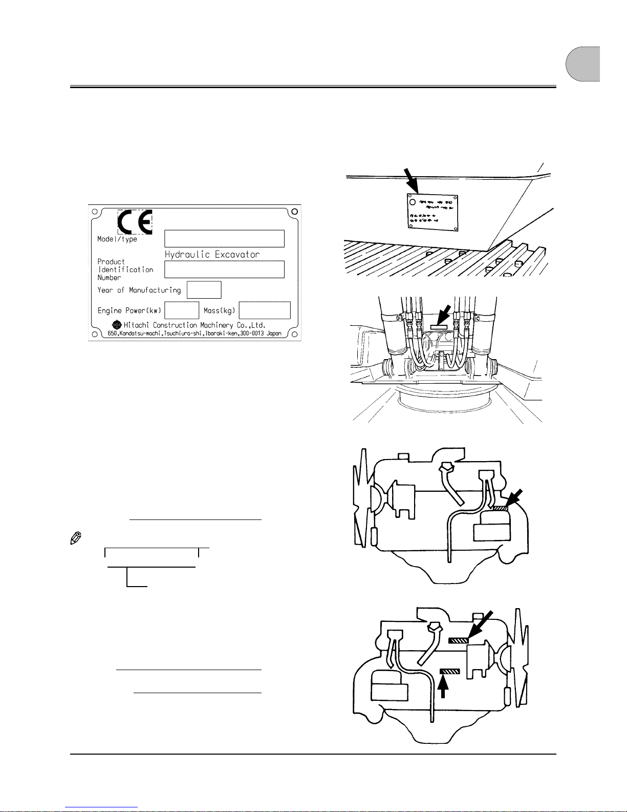
MACHINE NUMBERS
The manufacturing Nos. explained in this group is the individual number (serial No.) given to each machine and hydraulic
components. These numbers are requested when inquiring
any information on the machine and/or components. Fill these
serial Nos. in the blank spaces in this group to immediately
make them available upon request.
MACHINE
1. MODEL/TYPE
2. Product Identification Number
3. Year of Manufacturing
4. Operating mass (standard version)
5. Engine power in KW according to ISO9249
PRODUCT IDENTIFICATION NUMBER
PRODUCT
IDENTIFICATION
NUMBER:
NOTE:
*HCM1U100L00100001*
ENGINE
TYPE:
MFG. NO.:
M157-00-001
SS3097499
Marks to indicate the
start and end of the PIN
PRODUCT IDENTIFICATION
NUMBER (PIN)
(ZX330-3
class)
(ZX200-3,
270-3 class)
M178-00-002
M1U1-00-001
M157-12-008
(ZX120-3,
180-3 class)
Page 7
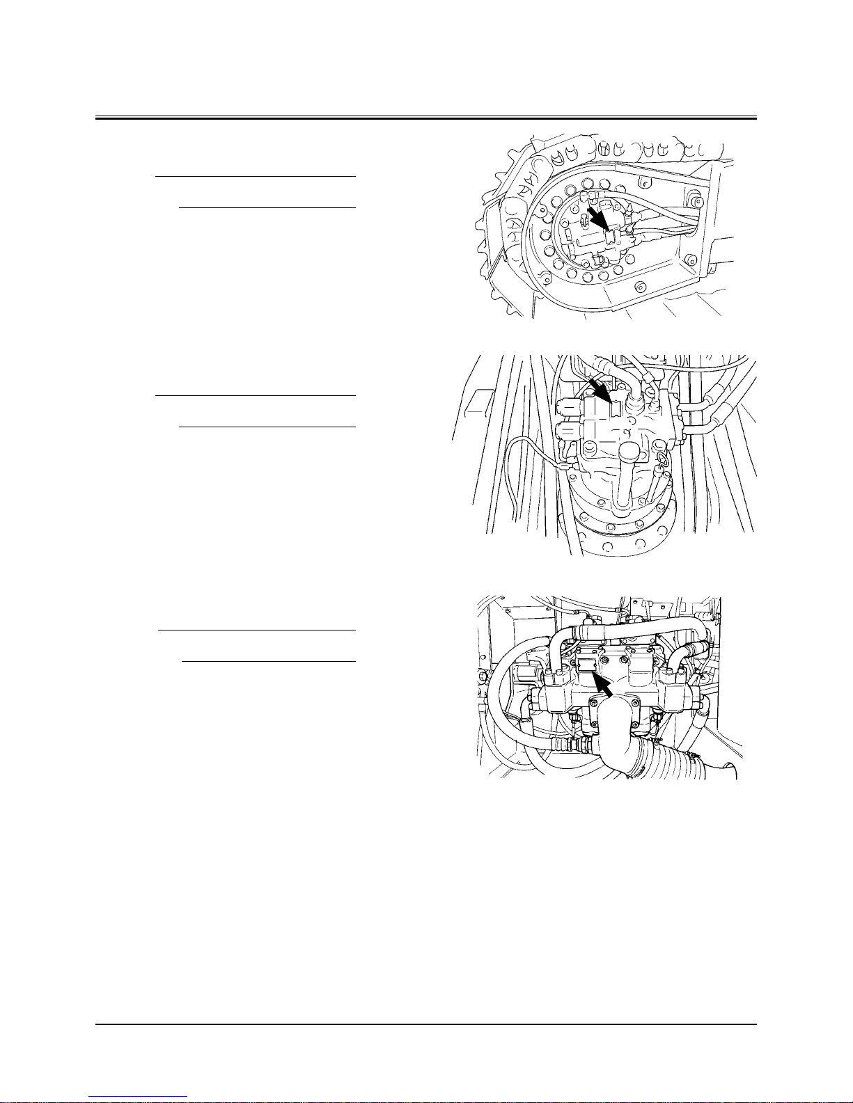
MACHINE NUMBERS
TRAVEL MOTOR
TYPE:
MFG. NO.:
SWING MOTOR
TYPE:
MFG. NO.:
HYDRAULIC PUMP
TYPE:
MFG. NO.:
M178-07-086
M178-07-047
M157-00-004
Page 8

CONTENTS
MACHINE NUMBERS
SAFETY
Recognize Safety Information ....................................................S-1
Understand Signal Words .............................................................S-1
Follow Safety Instructions ............................................................S-2
Prepare for Emergencies ...............................................................S-3
Wear Protective Clothing..............................................................S-3
Protect Against Noise ....................................................................S-3
Inspect Machine ..............................................................................S-4
General Precautions for Cab ........................................................S-4
Use Handholds and Steps ............................................................S-5
Adjust the Operator’s Seat ...........................................................S-5
Ensure Safety Before Rising from or
Leaving Operator’s Seat .........................................................S-5
Fasten Your Seat Belt ......................................................................S-6
Move and Operate Machine Safely ...........................................S-6
Handle Starting Aids Safely .........................................................S-6
Operate Only from Operator’s Seat ..........................................S-7
Jump Starting ...................................................................................S-7
Keep Riders Off Machine ..............................................................S-7
Precautions for Operations ..........................................................S-8
Investigate Job Site Beforehand ................................................S-9
Equipment of Head Guard, Rops, Fops ................................S-10
Provide Signals for Jobs Involving
Multiple Numbers of Machines ........................................S-10
Confirm Direction of Machine to Be Driven ........................ S-10
Drive Machine Safely ................................................................... S-11
Avoid Injury from Rollaway Accidents ..................................S-13
Avoid Injury from Back-over and Swing Accidents .......... S-14
Keep Person Clear from Working Area..................................S-15
Never Position Bucket Over Anyone ..................................... S-15
Avoid Undercutting .....................................................................S-15
Avoid Tipping ................................................................................. S-16
Never Undercut a High Bank ....................................................S-16
Dig with Caution ........................................................................... S-17
Operate with Caution .................................................................S-17
Avoid Power Lines ........................................................................S-18
Precautions for Lightning .......................................................... S-18
Object Handling ...........................................................................S-18
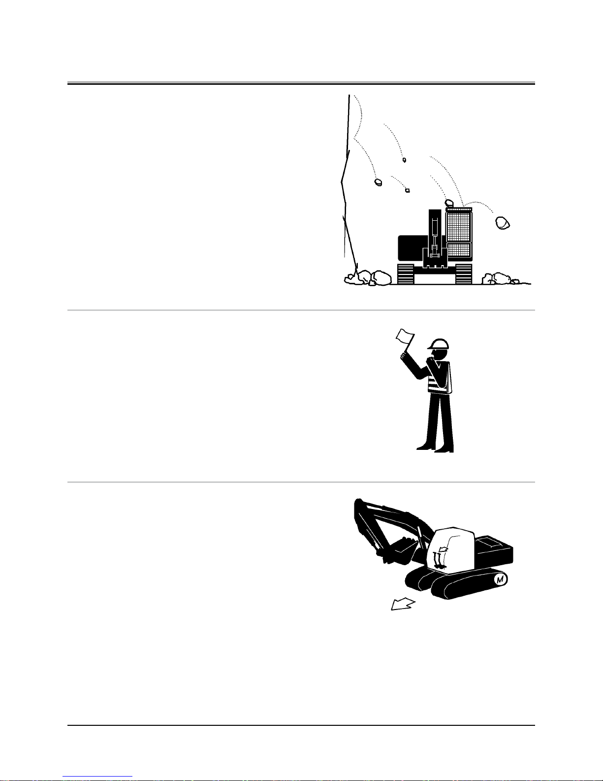
Protect Against Flying Debris ..................................................S-19
Park Machine Safely ..................................................................... S-19
Handle Fluids Safely−avoid Fires ............................................ S-19
Transport Safely ............................................................................ S-20
Practice Safe Maintenance ........................................................S-21
Warn Others of Service Work ...................................................S-22
Support Machine Properly ........................................................S-22
Stay Clear of Moving Parts ........................................................S-22
Prevent Parts from Flying .......................................................... S-23
Store Attachments Safely .......................................................... S-23
Prevent Burns ................................................................................. S-24
Replace Rubber Hoses Periodically ........................................ S-24
Avoid High-pressure Fluids ....................................................... S-25
Prevent Fires ................................................................................... S-26
Evacuating in Case of Fire ..........................................................S-27
Beware of Exhaust Fumes..........................................................S-27
Precautions for Welding and Grinding ................................. S-27
Avoid Heating Near Pressurized Fluid Lines ....................... S-28
Avoid Applying Heat to Lines Containing
Flammable Fluids ..................................................................S-28
Remove Paint Before Welding or Heating ...........................S-28
Beware of Asbestos Dust ........................................................... S-29
Prevent Battery Explosions ....................................................... S-29
Service Air Conditioning System Safely ...............................S-29
Handle Chemical Products Safely ........................................... S-30
Dispose of Waste Properly ......................................................... S-30
SAFETY SIGNS .............................................................................. S-31
COMPONENTS NAME ................................................................. 1-1
OPERATOR’S STATION
Cab Features ..................................................................................... 1-2
Multi Function Monitor ................................................................ 1-3
Outline ................................................................................................ 1-4
Menu Screen (23) ..................................................................... 1-7
Hour Meter ................................................................................. 1-8
Fuel Gauge ................................................................................. 1-8
Clock ............................................................................................. 1-8
Back Monitor Selector ............................................................ 1-8
Menu Key .................................................................................... 1-9
Optional Function Key ........................................................... 1-9
Return to Basic Screen Key .................................................. 1-9
Alarm Light ................................................................................ 1-9
Optional Function Display .................................................. 1-9
Coolant Temperature Gauge ............................................. 1-10
Operating Status Icon Display ..........................................1-10
Alarm Occurrence Screen ..........................................................1-15
Contents of Alarms ...................................................................... 1-17
Clock Setting .................................................................................. 1-19
Attachment Selection
(Only Machines Equipped with Optional Parts) .........1-20
Pump 2 Flow Rate Adjustment
(Only Machines Equipped with Optional Parts) .........1-24
Displaying Operating Conditions ...........................................1-25
Fuel Rate Display/No Display ................................................... 1-26
Back Monitor Settings ................................................................1-34
Maintenance Settings .................................................................1-36
Mail (Optional) ...............................................................................1-41
Language Settings ....................................................................... 1-43
Switch Panel ...................................................................................1-45
Engine Control Dial ...................................................................... 1-46
Auto-idle Switch ...........................................................................1-46
Power Mode Switch .................................................................... 1-47
Travel Mode Switch .....................................................................1-47
Work Light Switch ........................................................................ 1-48
Wiper/Washer Switch ..................................................................1-49
Switch Panel (Optional) .............................................................. 1-51
Key Switch .......................................................................................1-53
Power Boost Switch
(ZX180-3, 200-3, 270-3, 330-3 Class) .............................. 1-53
Page 9

CONTENTS
Horn Switch .................................................................................... 1-53
Cigar Lighter ................................................................................... 1-54
Cab Light .........................................................................................1-55
Installing Fire Extinguisher (Optional) .................................. 1-55
Pilot Control Shut-off Lever ...................................................... 1-56
Engine Stop Switch ...................................................................... 1-56
Fuse Box ...........................................................................................1-57
Auto Air Conditioner ...................................................................1-58
Cab Heater Operation .................................................................1-62
Cooling Operation .......................................................................1-62
Defroster Operation ....................................................................1-63
Tips for Optimal Air Conditioner Usage ............................... 1-64
Cab Heater (Optional) .................................................................1-65
Cab Heater Operation .................................................................1-66
Defroster Operation ....................................................................1-67
AM/FM Radio Operation ............................................................1-68
Digital Clock Setting Procedure ..............................................1-69
Cab Door Release Lever .............................................................1-70
Opening Upper Front Window ................................................1-70
Closing Upper Front Window ................................................... 1-71
Removing and Storing Lower Front Window ..................... 1-72
Opening Side Windows ..............................................................1-72
Opening/Closing Overhead Window .................................... 1-73
Emergency Exit .............................................................................1-74
Adjusting the Seat ....................................................................... 1-75
Seat with a Built-in Heater.........................................................1-76
Adjusting the Air-suspension Seat (Optional) ...................1-77
Seat with a Built-in Heater.........................................................1-78
Adjusting Console Height ......................................................... 1-79
Seat Belt ........................................................................................... 1-80
BREAK-IN
Observe Engine Operation Closely .......................................... 2-1
Every 8 Hours or Daily ................................................................... 2-1
After the First 50 Hours ................................................................ 2-1
After the First 100 Hours .............................................................. 2-1
OPERATING THE ENGINE
Inspect Machine Daily Before Starting ................................... 3-1
Before Starting Engine ................................................................. 3-2
Starting the Engine in Ordinary Temperature ...................... 3-3
Starting in Cold Weather.............................................................. 3-5
Check Instruments After Starting ............................................. 3-7
Using Booster Batteries ................................................................ 3-8
Stopping the Engine ...................................................................3-10
DRIVING THE MACHINE
Drive the Machine Carefully ....................................................... 4-1
Steering the Machine Using Pedals ......................................... 4-2
Steering the Machine Using Levers ......................................... 4-3
Travel Mode Switch ....................................................................... 4-4
Travel Alarm (Optional) ................................................................ 4-4
Operating on Soft Ground .......................................................... 4-5
Raise One Track Using Boom and Arm ................................... 4-5
Towing Machine a Short Distance ............................................ 4-6
Operating in Water or Mud ......................................................... 4-7
Parking the Machine on Slopes ................................................. 4-8
Parking the Machine ..................................................................... 4-8
OPERATING THE MACHINE
Control Lever (ISO Pattern) ......................................................... 5-1
Attachment Pedal (Hydraulic Breaker) (Optional) .............. 5-2
Attachment Pedal (Hydraulic Crusher) (Optional) .............. 5-3
Pilot Control Shut-off Lever ........................................................ 5-4
Engine Speed Control ................................................................... 5-6
Auto-idle ............................................................................................ 5-7
Work Mode ....................................................................................... 5-8
Work Mode Select .......................................................................... 5-9
Power Boost (ZX180-3, 200-3, 270-3, 330-3 Class)............5-10
Power Mode ................................................................................... 5-11
Operating Backhoe ......................................................................5-12
Grading Operation .......................................................................5-12
Face Shovel Operation................................................................5-13
Avoid Abusive Operation .......................................................... 5-13
Operating Tips ...............................................................................5-14
Select Correct Track Shoes ........................................................ 5-14
Hydraulic Breaker and Hydraulic Crusher ............................ 5-15
Pipings for Breaker and Crusher (Optional) ........................ 5-16
Secondary Relief Pressure Adjustment ................................5-18
Precautions for Breaker Operation ......................................... 5-20
Breaker Maintenance .................................................................. 5-23
Precautions for Crusher Operation ........................................ 5-24
Attachment ..................................................................................... 5-26
Attachment Connection Parts ................................................. 5-30
Precaution for Arm Roll-in/Bucket Roll-in
Combined Operation --- If Headguard-Integrated
Cab or Rainguard is Equipped ..........................................5-31
When Installing an Attachment Longer
Than Standard Bucket ..........................................................5-31
Shackle Hole Usage .....................................................................5-32
Overnight Storage Instructions ...............................................5-32
Emergency Boom Lowering Procedure
(Without hose-rupture safety valve) ..............................5-33
Object Handling --- If Equipped ..............................................5-35
TRANSPORTING
Transporting By Road ................................................................... 6-1
Loading/unloading on a Trailer ................................................. 6-1
Machine Lifting Procedure .......................................................... 6-5
MAINTENANCE
Correct Maintenance and Inspection Procedures .............. 7-1
Check the Hour Meter Regularly ............................................... 7-2
Use Correct Fuels and Lubricants ............................................. 7-2
Layout ................................................................................................. 7-3
Maintenance Guide Table ............................................................ 7-4
Prepare Machine for Maintenance ........................................... 7-6
Hood and Access Covers (ZX120-3, 180-3 Class) ................ 7-7
Hood and Access Covers (ZX200-3, 270-3, 330-3 Class) ... 7-8
Periodic Replacement of Parts ................................................... 7-9
Page 10

CONTENTS
Maintenance Guide ..................................................................... 7-10
A. Greasing ......................................................................................7-16
Front Joint Pins .......................................................................7-16
Swing Bearing ......................................................................... 7-18
Swing Internal Gear ..............................................................7-19
B. Engine ..........................................................................................7-20
Engine Oil Level ......................................................................7-20
Change Engine Oil ................................................................ 7-21
Replace Engine Oil Filter .....................................................7-21
C. Transmission .............................................................................. 7-23
Pump Transmission ............................................................... 7-23
Swing Reduction Gear ......................................................... 7-24
Travel Reduction Gear ..........................................................7-25
D. Hydraulic System ..................................................................... 7-27
Inspection and Maintenance of Hydraulic
Equipment...........................................................................7-27
Breaker Maintenance ...........................................................7-29
Check Hydraulic Oil Level ...................................................7-30
Change Hydraulic Oil ...........................................................7-31
Suction Filter Cleaning ........................................................7-31
Replace Hydraulic Oil Tank Filter ......................................7-34
Replace Pilot Oil Filter ..........................................................7-35
Replace Air Breather Element ...........................................7-36
Check Hoses and Lines ........................................................7-37
Service Recommendations for Hydraulic Fittings .....7-40
E. Fuel System ................................................................................7-42
Drain Fuel Tank Sump .........................................................7-44
Drain Fuel Filter ......................................................................7-45
Replace Fuel Main Filter Element ..................................... 7-49
Replace Fuel Pre-Filter Element ........................................ 7-50
Clean Fuel Solenoid Pump Strainer ................................7-51
Check Fuel Hoses ................................................................... 7-52
F. Air Cleaner ...................................................................................7-53
Clean Air Cleaner Outer Element .....................................7-53
Replace Air Cleaner Outer and Inner Elements ..........7-53
G. Cooling System ........................................................................ 7-55
Check Coolant Level .............................................................7-57
Check and Adjust Fan Belt Tension
(ZX120-3, 180-3 Class) .....................................................7-58
Check and Adjust Fan Belt Tension
(ZX200-3, ZX270-3, ZX330-3 Class) ............................. 7-59
Change Coolant .....................................................................7-60
Clean Radiator Interior.........................................................7-60
Clean Radiator, Oil Cooler Core
and Inter Cooler Outside ................................................ 7-61
Clean Oil Cooler, Radiator and Inter
Cooler Front Screen ......................................................... 7-61
Clean Air Conditioner Condenser .................................... 7-61
Clean Fuel Oil Cooler ........................................................... 7-61
Clean Air Conditioner Front Screen (Opt.) ....................7-61
H. Electrical System ......................................................................7-62
Batteries ....................................................................................7-62
Replace Batteries ...................................................................7-65
Replacing Fuses ......................................................................7-66
I. Miscellaneous ............................................................................7-68
Check Bucket Teeth ...............................................................7-68
Change Bucket .......................................................................7-72
Convert Bucket Connection Into Face Shovel .............7-73
Adjust Bucket Linkage .........................................................7-74
Remove Travel Levers ...........................................................7-75
Check and Replace Seat Belt Check ................................ 7-75
Check Windshield Washer Fluid Level ............................7-76
Check Track Sag ...................................................................... 7-77
Clean and Replace Air Conditioner Filter ...................... 7-79
Check Air Conditioner ..........................................................7-81
Clean Cab Floor ......................................................................7-82
Retighten Cylinder Head Bolt............................................ 7-83
Inspect and Adjust Valve Clearance ................................7-83
Measure Engine Compression Pressure ........................ 7-83
Check Starter and Alternator.............................................7-83
Check and Replace EGR Device ........................................7-83
Check Tightening Torque of Bolts and Nuts ................7-84
HYDRAULIC CIRCUIT AND ELECTRICAL CIRCUIT
Hydraulic Circuit ............................................................................. 8-1
Electrical Circuit .............................................................................. 8-2
Electrical Diagram .......................................................................... 8-3
MAINTENANCE UNDER SPECIAL
ENVIRONMENTAL CONDITIONS
Maintenance Under Special Environmental
Conditions .................................................................................. 9-1
STORAGE
Storing the Machine ....................................................................10-1
Removing the Machine from Storage ................................... 10-2
TROUBLESHOOTING
Impossible to Start the Engine ................................................11-1
Engine ............................................................................................... 11-2
Electrical System ...........................................................................11-6
Mode Selection .............................................................................11-8
Control Levers ................................................................................ 11-9
Hydraulic System ..........................................................................11-9
SPECIFICATIONS
Specifications (ZX110-3, 110M-3) ...........................................12-1
Working Ranges (ZX110-3, 110M-3) ......................................12-2
Shoe Types and Applications
(ZX110-3) ..................................................................................12-3
(ZX110M-3) ..............................................................................12-4
Bucket Types and Applications (ZX110-3, 110M-3) .......... 12-5
Specifications (ZX130-3, 130LCN-3) .......................................12-6
Working Ranges (ZX130-3, 130LCN-3) .................................. 12-7
Shoe Types and Applications (ZX130-3)...............................12-8
Shoe Types and Applications (ZX130LCN-3) ...................... 12-9
Bucket Types and Applications (ZX130-3, 130LCN-3) ...12-10
Specifications (ZX160LC-3) .....................................................12-11
Working Ranges (ZX160LC-3) ................................................12-12
Shoe Types and Applications (ZX160LC-3) ........................12-14
Bucket Types and Applications (ZX160LC-3) ....................12-15
Page 11

CONTENTS
Specifications (ZX180LC-3, 180LCN-3) ................................12-16
Working Ranges (ZX180LC-3, 180LCN-3) ...........................12-17
Shoe Types and Applications
(ZX180LC-3, 180LCN-3) ......................................................12-19
Bucket Types and Applications
(ZX180LC-3, 180LCN-3) ......................................................12-20
Specifications (ZX210-3, 210LC-3) ........................................12-21
Working Ranges (ZX210-3, 210LC-3) ...................................12-22
Shoe Types and Applications (ZX210-3, 210LC-3) ..........12-23
Bucket Types and Applications (ZX210-3, 210LC-3) .......12-24
Specifications (ZX210LCN-3, 240N-3) .................................12-25
Working Ranges (ZX210LCN-3, 240N-3).............................12-26
Shoe Types and Applications
(ZX210LCN-3, 240N-3) .......................................................12-27
Bucket Types and Applications
(ZX210LCN-3, 240N-3) .......................................................12-28
Specifications (ZX250LC-3, 250LCN-3) ................................12-29
Working Ranges (ZX250LC-3, 250LCN-3) ...........................12-30
Shoe Types and Applications
(ZX250LC-3, 250LCN-3) ......................................................12-31
Bucket Types and Applications
(ZX250LC-3, 250LCN-3) ......................................................12-32
Specifications (ZX280LC-3, 280LCN-3) ................................12-33
Working Ranges (ZX280LC-3, 280LCN-3) ...........................12-34
Shoe Types and Applications
(ZX280LC-3, 280LCN-3) ......................................................12-35
Bucket Types and Applications
(ZX280LC-3, 280LCN-3) ......................................................12-36
Specifications (ZX350LC-3, 350LCN-3) ................................12-37
Working Ranges (ZX350LC-3, 350LCN-3) ...........................12-38
Shoe Types and Applications
(ZX350LC-3, 350LCN-3) ......................................................12-39
Bucket Types and Applications
(ZX350LC-3, 350LCN-3) ......................................................12-40
Sound Level Results (2000/14/EC) .......................................12-41
Vibration Level .............................................................................12-41
OPTIONAL ATTACHMENTS AND DEVICES
Using Pad Crawler Shoe .............................................................13-1
Traveling and Other Cautions ..................................................13-2
Transporting ................................................................................... 13-3
Precautions for Transporting Machines
with Pad Crawler Shoes .......................................................13-3
Long Arm Operation --- If Equipped ...................................... 13-6
Blade Lever .....................................................................................13-7
Precautions for Blade Operation .............................................13-7
Avoid Hitting Blade with Front-end Attachment..............13-8
Avoid Hitting Blade with Bucket .............................................13-8
Avoid Striking The Blade Into a Rock .....................................13-8
Blade Maintenance ...................................................................... 13-9
Specifications (ZX110-3 with Blade) ....................................13-10
Working Ranges (ZX110-3 with Blade) ...............................13-11
Shoe Types and Applications (ZX110-3 with Blade) ......13-12
Specifications (ZX130-3 with Blade) ....................................13-13
Working Ranges (ZX130-3 with Blade) ...............................13-14
Shoe Types and Applications (ZX130-3 with Blade) ......13-15
Offset Arm Front .........................................................................13-16
Offset Direction and Working Range ..................................13-17
Precautions for Operating with The Offset Function .....13-18
Maintenance ................................................................................13-19
Specifications (ZX110-3, 110M-3 Offset) ............................13-20
Working Ranges (ZX110-3, 110M-3 Offset) .......................13-21
Bucket Teeth (Transverse-type-pin-used Type) ...............13-22
2-piece Boom ...............................................................................13-23
Maintenance (2-piece Boom) .................................................13-24
Specifications
ZX130-3, 130LCN-3 (2-piece Boom) ..............................13-27
Working Ranges
ZX130-3, 130LCN-3 (2-piece Boom) ..............................13-28
Shoe Types and Applications
ZX130-3 (2-piece Boom) ...................................................13-29
ZX130LCN-3 (2-piece Boom) ...........................................13-30
Specifications
ZX210-3, 210LC-3 (2-piece Boom) .................................13-31
Working Ranges
ZX210-3, 210LC-3 (2-piece Boom) .................................13-32
Shoe Types and Applications
ZX210-3 (2-piece Boom) ...................................................13-33
ZX210LC-3 (2-piece Boom) ..............................................13-33
Specifications
ZX210LCN-3, 240N-3 (2-piece Boom) ...........................13-34
Working Ranges
ZX210LCN-3, 240N-3 (2-piece Boom) ...........................13-35
Shoe Types and Applications
ZX210LCN-3 (2-piece Boom) ...........................................13-36
ZX240N-3 (2-piece Boom) ................................................13-36
Specifications
ZX250LC-3, 250LCN-3 (2-piece Boom) .........................13-37
Working Ranges
ZX250LC-3, 250LCN-3 (2-piece Boom) .........................13-38
Shoe Types and Applications
ZX250LC-3 (2-piece Boom) ..............................................13-39
ZX250LCN-3 (2-piece Boom) ...........................................13-39
Specifications
ZX280LC-3, 280LCN-3 (2-piece Boom) .........................13-40
Working Ranges
ZX280LC-3, 280LCN-3 (2-piece Boom) .........................13-41
Shoe Types and Applications
ZX280LC-3 (2-piece Boom) ..............................................13-42
ZX280LCN-3 (2-piece Boom) ...........................................13-42
Specifications
ZX350LC-3, 350LCN-3 (2-piece Boom) .........................13-43
Working Ranges
ZX350LC-3, 350LCN-3 (2-piece Boom) .........................13-44
Shoe Types and Applications
ZX350LC-3 (2-piece Boom) ..............................................13-45
ZX350LCN-3 (2-piece Boom) ...........................................13-45
Lifting Hook ..................................................................................13-46
Lifting Capacities ........................................................................13-48
INDEX ...............................................................................................14-1
Page 12

SAFETY
S-1
SA-688
SA-1223
RECOGNIZE SAFETY INFORMATION
•
These are the SAFETY ALERT SYMBOLS.
• When you see these symbols on your machine or in this
manual, be alert to the potential for personal injury.
• Follow recommended precautions and safe operating
practices.
001-E01A-0001
UNDERSTAND SIGNAL WORDS
•
On machine safety signs, signal words designating the
degree or level of hazard - DANGER, WARNING, or CAUTION
- are used with the safety alert symbol.
•
DANGER indicates an imminently hazardous situation
which, if not avoided, will result in death or serious injury.
•
WARNING indicates a potentially hazardous situation
which, if not avoided, could result in death or serious
injury.
•
CAUTION indicates a potentially hazardous situation
which, if not avoided, may result in minor or moderate
injury.
•
DANGER or WARNING safety signs are located near spe-
cific hazards. General precautions are listed on CAUTION
safety signs.
• Some safety signs do not use any of the designated signal
words above after the safety alert symbol are occasionally
used on this machine.
•
To avoid confusing machine protection with personal safety
messages, a signal word IMPORTANT indicates a situation
which, if not avoided, could result in damage to the machine.
•
NOTE indicates an additional explanation for an element
of information.
002-E01A-1223
Page 13
SAFETY
S-2
FOLLOW SAFETY INSTRUCTIONS
•
Carefully read and follow all safety signs on the machine
and all safety messages in this manual.
•
Safety signs should be installed, maintained and replaced
when necessary.
• If a safety sign or this manual is damaged or missing,
order a replacement from your authorized dealer in the
same way you order other replacement parts (be sure to
state machine model and serial number when ordering).
•
Learn how to operate the machine and its controls correctly
and safely.
•
Allow only trained, qualified, authorized personnel to oper
-
ate the machine.
•
Keep your machine in proper working condition.
• Unauthorized modifications of the machine may impair
its function and/or safety and affect machine life.
• Do not modify any machine parts without authorization.
Failure to do so may deteriorate the part safety, function, and/or service life. In addition, personal accident,
machine trouble, and/or damage to material caused by
unauthorized modifications will void Hitachi Warranty
Policy.
• Do not use attachments and/or optional parts or equip
ment not authorized by Hitachi. Failure to do so may
deteriorate the safety, function, and/or service life of the
machine. In addition, personal accident, machine trouble,
and/or damage to material caused by using unauthorized
attachments and/or optional parts or equipment will void
Hitachi Warranty Policy.
•
The safety messages in this SAFETY chapter are intended to
illustrate basic safety procedures of machines. However it is
impossible for these safety messages to cover every hazardous situation you may encounter. If you have any questions,
you should first consult your supervisor and/or your authorized dealer before operating or performing maintenance
work on the machine.
003-E01B-0003
SA-003
Page 14

SAFETY
S-3
PREPARE FOR EMERGENCIES
•
Be prepared if a fire starts or if an accident occurs.
• Keep a first aid kit and fire extinguisher on hand.
• Thoroughly read and understand the label attached on
the fire extinguisher to use it properly.
• To ensure that a fire extinguisher can be always used
when necessary, check and service the fire extinguisher at
the recommended intervals as specified in the fire extinguisher manual.
• Establish emergency procedure guidelines to cope with
fires and accidents.
• Keep emergency numbers for doctors, ambulance service,
hospital, and fire department posted near your telephone.
004-E01A-0437
WEAR PROTECTIVE CLOTHING
•
Wear close fitting clothing and safety equipment appropri-
ate to the job.
You may need:
A hard hat
Safety shoes
Safety glasses, goggles, or face shield
Heavy gloves
Hearing protection
Reflective clothing
Wet weather gear
Respirator or filter mask.
Be sure to wear the correct equipment and clothing for the
job. Do not take any chances.
• Avoid wearing loose clothing, jewelry, or other items that
can catch on control levers or other parts of the machine.
•
Operating equipment safely requires the full attention of
the operator. Do not wear radio or music headphones while
operating the machine.
005-E01A-0438
PROTECT AGAINST NOISE
•
Prolonged exposure to loud noise can cause impairment or
loss of hearing.
• Wear a suitable hearing protective device such as ear
muffs or earplugs to protect against objectionable or
uncomfortably loud noises.
006-E01A-0434
SA-437
SA-434
SA-438
Page 15

SAFETY
S-4
INSPECT MACHINE
•
Inspect your machine carefully each day or shift by walking
around it before you start it to avoid personal injury.
• In the walk-around inspection be sure to cover all points
described in the “PRE-START INSPECTION” chapter in the
operator’s manual.
007-E01A-0435
GENERAL PRECAUTIONS FOR CAB
• Before entering the cab, thoroughly remove all dirt and/
or oil from the soles of your work boots. If any controls
such as a pedal is operated while with dirt and/or oil on
the soles of the operator’s work boots the operator’s foot
may slip off the pedal, possibly resulting in a personal accident.
• Do not leave parts and/or tools lying around the opera-
tor’s seat. Store them in their specified locations.
• Avoid storing transparent bottles in the cab. Do not at
tach any transparent type window decorations on the
windowpanes as they may focus sunlight, possibly starting a fire.
• Refrain from listening to the radio, or using music head
phones or mobile telephones in the cab while operating
the machine.
• Keep all flammable objects and/or explosives away from
the machine.
• After using the ashtray, always cover it to extinguish the
match and/or tobacco.
• Do not leave cigarette lighters in the cab. When the tem
-
perature in the cab increases, the lighter may explode.
524-E01A-0000
SA-435
Page 16
SAFETY
S-5
USE HANDHOLDS AND STEPS
•
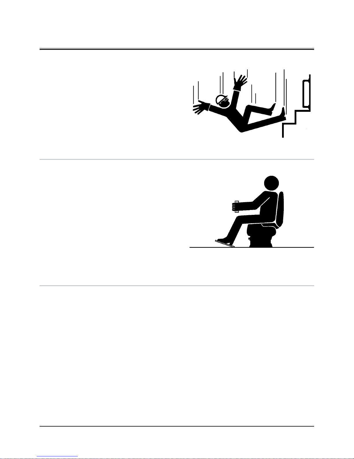
Falling is one of the major causes of personal injury.
• When you get on and off the machine, always face the
machine and maintain a three-point contact with the
steps and handrails.
• Do not use any controls as hand-holds.
• Never jump on or off the machine. Never mount or dis
-
mount a moving machine.
• Be careful of slippery conditions on platforms, steps, and
handrails when leaving the machine.
008-E01A-0439
ADJUST THE OPERATOR'S SEAT
•
A poorly adjusted seat for either the operator or for the
work at hand may quickly fatigue the operator leading to
misoperations.
• The seat should be adjusted whenever changing the op
-
erator for the machine.
• The operator should be able to fully depress the pedals
and to correctly operate the control levers with his back
against the seat back.
• If not, move the seat forward or backward, and check
again.
• Adjust the rear view mirror position so that the best rear
visibility is obtained from the operator’s seat. If the mirror
is broken, immediately replace it with a new one.
009-E01A-0462
ENSURE SAFETY BEFORE RISING FROM OR LEAVING OPERATOR’S SEAT
•
Before rising from the operator’s seat to open/close either
side window or to adjust the seat position, be sure to first
lower the front attachment to the ground and then move
the pilot control shut-off lever to the LOCK position. Failure
to do so may allow the machine to unexpectedly move
when a body part unintentionally comes in contact with a
control lever, possibly resulting in serious personal injury or
death.
•
Before leaving the machine, be sure to first lower the front
attachment to the ground and then move the pilot control
shut-off lever to the LOCK position. Turn the key switch OFF
to stop the engine.
•
Before leaving the machine, close all windows, doors, and
access covers and lock them up.
SA-439
SA-378
Page 17
SAFETY
S-6
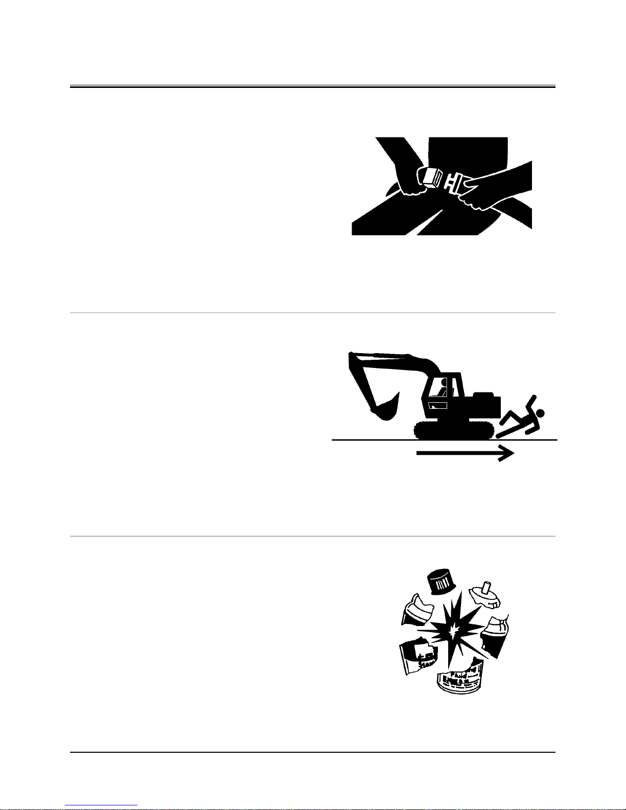
FASTEN YOUR SEAT BELT
•
If the machine should overturn, the operator may become
injured and/or thrown from the cab. Additionally the operator may be crushed by the overturning machine, resulting in
serious injury or death.
• Prior to operating the machine, thoroughly examine web
bing, buckle and attaching hardware. If any item is damaged or worn, replace the seat belt or component before
operating the machine.
• Be sure to remain seated with the seat belt securely
fastened at all times when the machine is in operation to
minimize the chance of injury from an accident.
• We recommend that the seat belt be replaced every three
years regardless of its apparent condition.
010-E01A-0237
MOVE AND OPERATE MACHINE SAFELY
•
Bystanders can be run over.
• Take extra care not to run over bystanders. Confirm the
location of bystanders before moving, swinging, or operating the machine.
• Always keep the travel alarm and horn in working condi
tion (if equipped). It warns people when the machine
starts to move.
• Use a signal person when moving, swinging, or operating
the machine in congested areas. Coordinate hand signals
before starting the machine.
• Use appropriate illumination. Check that all lights are op
erable before operating the machine. If any faulty illumination is present, immediately repair it.
011-E01A-0398
HANDLE STARTING AIDS SAFELY
Starting fluid:
•
Starting fluid is highly flammable.
• Keep all sparks and flame away when using it.
• Keep starting fluid well away from batteries and cables.
• Remove container from machine if engine does not need
starting fluid.
• To prevent accidental discharge when storing a pressur
ized container, keep the cap on the container, and store it
in a cool, well-protected location.
• Do not incinerate or puncture a starting fluid container.
036-E01A-0293-3
SA-237
SA-426
SA-293
Page 18
SAFETY
S-7
OPERATE ONLY FROM OPERATOR'S SEAT
•
Inappropriate engine starting procedures may cause the
machine to runaway, possibly resulting in serious injury or
death.
• Start the engine only when seated in the operator's seat.
• NEVER start the engine while standing on the track or on
ground.
• Do not start engine by shorting across starter terminals.
• Before starting the engine, confirm that all control levers
are in neutral.
• Before starting the engine, confirm the safety around the
machine and sound the horn to alert bystanders.
012-E01B-0431
JUMP STARTING
•
Battery gas can explode, resulting in serious injury.
• If the engine must be jump started, be sure to follow the
instructions shown in the “OPERATING THE ENGINE” chapter in the operator’s manual.
• The operator must be in the operator’s seat so that the
machine will be under control when the engine starts.
Jump starting is a two-person operation.
• Never use a frozen battery.
• Failure to follow correct jump starting procedures could
result in a battery explosion or a runaway machine.
S013-E01A-0032
KEEP RIDERS OFF MACHINE
•
Riders on machine are subject to injury such as being struck
by foreign objects and being thrown off the machine.
• Only the operator should be on the machine. Keep riders
off.
• Riders also obstruct the operator’s view, resulting in the
machine being operated in an unsafe manner.
014-E01B-0427
SA-444
SA-032
SA-379
Page 19
SAFETY
S-8
PRECAUTIONS FOR OPERATIONS
•
Investigate the work site before starting operations.
• Be sure to wear close fitting clothing and safety equip
ment appropriate for the job, such as a hard hat, etc.
when operating the machine.
• Clear all persons and obstacles from area of operation and
machine movement.
Always beware of the surroundings while operating.
When working in a small area surrounded by obstacles,
take care not to hit the upperstructure against obstacles.
• When loading onto trucks, bring the bucket over the truck
beds from the rear side. Take care not to swing the bucket
over the cab or over any person.
M178-05-007
Page 20
SAFETY
S-9
INVESTIGATE JOB SITE BEFOREHAND
•
When working at the edge of an excavation or on a road
shoulder, the machine could tip over, possibly resulting in
serious injury or death.
• Investigate the configuration and ground conditions of
the job site beforehand to prevent the machine from falling and to prevent the ground, stockpiles, or banks from
collapsing.
• Make a work plan. Use machines appropriate to the work
and job site.
• Reinforce ground, edges, and road shoulders as necessary.
Keep the machine well back from the edges of excavations and road shoulders.
• When working on an incline or on a road shoulder, em
-
ploy a signal person as required.
• Confirm that your machine is equipped a FOPS cab before
working in areas where the possibility of falling stones or
debris exist.
• When the footing is weak, reinforce the ground before
starting work.
• When working on frozen ground, be extremely alert. As
ambient temperatures rise, footing becomes loose and
slippery.
• Beware the possibility of fire when operating the machine
near flammable objects such as dry grass.
•
Make sure the worksite has sufficient strength to firmly sup-
port the machine.
When working close to an excavation or at road shoulders,
operate the machine with the tracks positioned perpendicular to the cliff face with travel motors at the rear, so that the
machine can more easily evacuate if the cliff face collapses.
•
If working on the bottom of a cliff or a high bank is required,
be sure to investigate the area first and confirm that no
danger of the cliff or bank collapsing exists. If any possibility
of cliff or bank collapsing exists, do not work on the area.
•
Soft ground may collapse when operating the machine on
it, possibly causing the machine to tip over. When working
on soft ground is required, be sure to reinforce the ground
first using large pieces of steel plates strong and firm
enough to easily support the machine.
•
Note that there is always a possibility of machine tipping
over when working on rough terrain or on slopes. Prevent
machine tipping over from occurring. When operating on
rough terrain or on slopes:
• Reduce the engine speed.
• Select slow travel speed mode.
• Operate the machine slowly and be cautious with ma
-
chine movements.
SA-380
M104-05-016
Page 21
SAFETY
S-10
EQUIPMENT OF HEAD GUARD, ROPS, FOPS
In case the machine is operated in areas where the possibility
of falling stones or debris exist, equip a head guard, ROPS, or
FOPS according to the potential hazardous conditions. (The
standard cab for this machine corresponds to ROPS and FOPS.)
ROPS: Roll-Over Protective Structure
FOPS: Falling Object Protective Structure
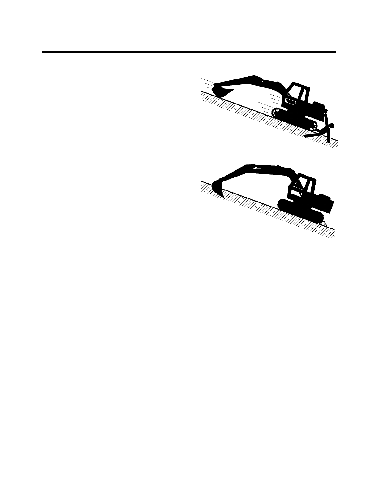
PROVIDE SIGNALS FOR JOBS INVOLVING MULTIPLE NUMBERS OF MACHINES
•
For jobs involving multiple numbers of machines, provide
signals commonly known by all personnel involved. Also,
appoint a signal person to coordinate the job site. Make
sure that all personnel obey the signal person’s directions.
018-E01A-0481
CONFIRM DIRECTION OF MACHINE TO BE DRIVEN
•
Incorrect travel pedal/lever operation may result in serious
injury death.
• Before driving the machine, confirm the position of the
undercarriage in relation to the operator’s position. If the
travel motors are located in front of the cab, the machine
will move in reverse when travel pedals/levers are operated to the front.
017-E01A-0491
SA-490
SA-481
SA-491
Page 22

SAFETY
S-11
DRIVE MACHINE SAFELY
•
Before driving the machine, always confirm that the travel
levers/pedals direction corresponds to the direction you
wish to drive.
• Be sure to detour around any obstructions.
• Avoid traveling over obstructions. Soil, fragments of rocks,
and/or metal pieces may scatter around the machine. Do
not allow personnel to stay around the machine while
traveling.
•
Driving on a slope may cause the machine to slip or over-
turn, possibly resulting in serious injury or death.
• Never attempt to ascend or descend 35 degrees or steep
-
er slopes.
• Be sure to fasten the seat belt.
• When driving up or down a slope, keep the bucket fac
ing the direction of travel, approximately 0.5 to 1.0 m (A)
above the ground.
• If the machine starts to skid or becomes unstable, imme
-
diately lower the bucket to the ground and stop.
A
A
SA-657
SA-658
SA-441
SA-590
WRONG
Page 23

SAFETY
S-12
• Driving across the face of a slope or steering on a slope
may cause the machine to skid or turnover. If the direction must be changed, move the machine to level ground,
then, change the direction to ensure safe operation.
• Avoid swinging the upperstructure on slopes. Never at
tempt to swing the upperstructure downhill. The machine
may tip over. If swinging uphill is unavoidable, carefully
operate the upperstructure and boom at slow speed.
• If the engine stalls on a slope, immediately lower the
bucket to the ground. Return the control levers to neutral.
Then, restart the engine.
• Be sure to thoroughly warm up the machine before as
cending steep slopes. If hydraulic oil has not warmed up
sufficiently, sufficient performance may not be obtained.
• Use a signal person when moving, swinging or operating
the machine in congested areas. Coordinate hand signals
before starting the machine.
• Before moving machine, determine which way to move
travel pedals/levers for the direction you want to go.
When the travel motors are in the rear, pushing down on
the front of the travel pedals or pushing the levers forward moves the machine forward, towards the idlers.
An arrow-mark seal is stuck on the inside surface of the
side frame to indicate the machine front direction.
• Select a travel route that is as flat as possible. Steer the
machine as straight as possible, making small gradual
changes in direction.
• Before traveling on them, check the strengths of bridges
and road shoulders, and reinforce if necessary.
• Use wood plates in order not to damage the road surface.
Be careful of steering when operating on asphalt roads in
summer.
• When crossing train tracks, use wood plates in order not
to damage them.
• Do not make contact with electric wires or bridges.
• When crossing a river, measure the depth of the river
using the bucket, and cross slowly. Do not cross the river
when the depth of the river is deeper than the upper
edge of the upper roller.
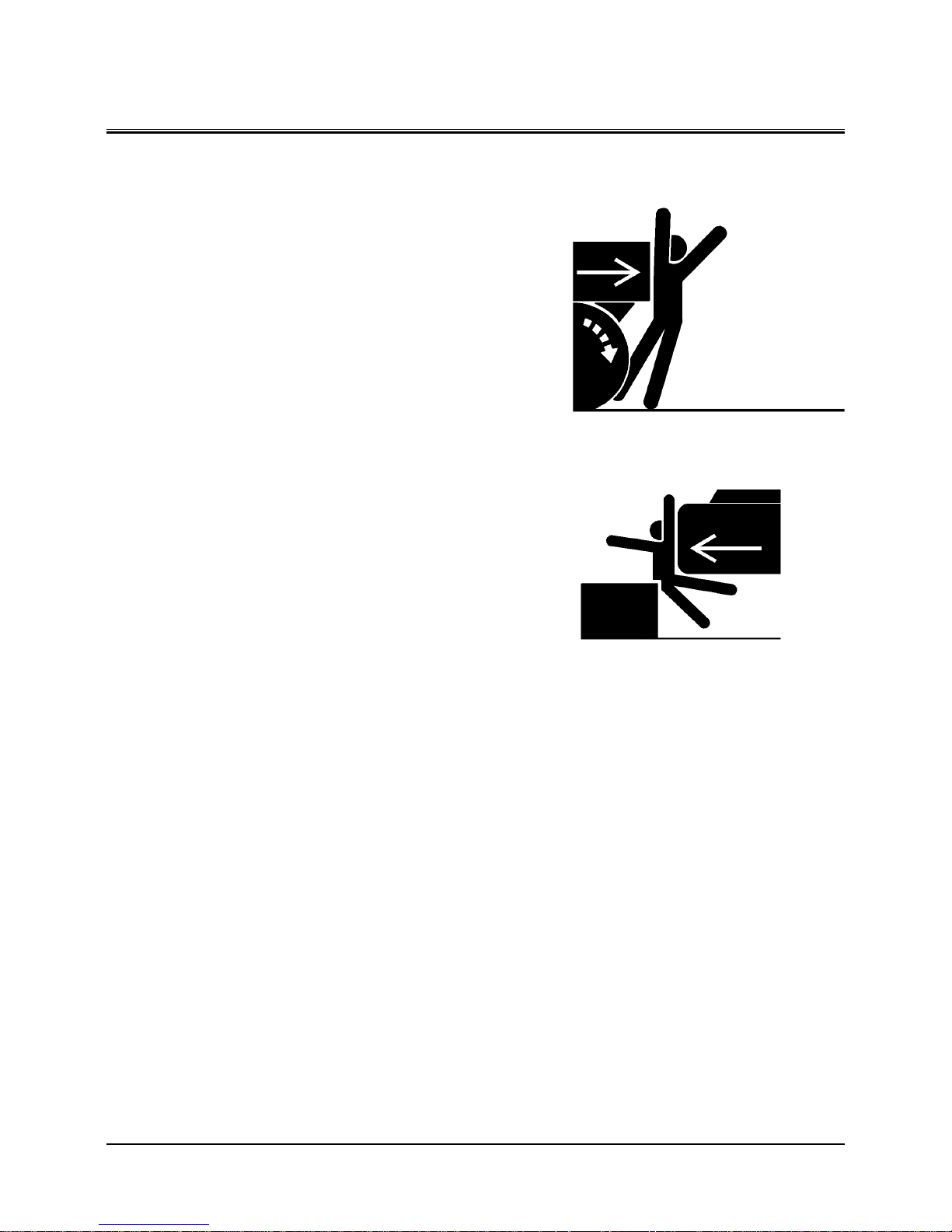
• When traveling on rough terrain, reduce engine speed.
Select slow travel speed. Slower speed will reduce possible damage to the machine.
• Avoid operations that may damage the track and under
-
carriage components.
• During freezing weather, always clean snow and ice from
track shoes before loading and unloading machine, to
prevent the machine from slipping.
Travel Motor
Arrow -mark
M104-05-008
M178-03-001
SA-011
Page 24
SAFETY
S-13
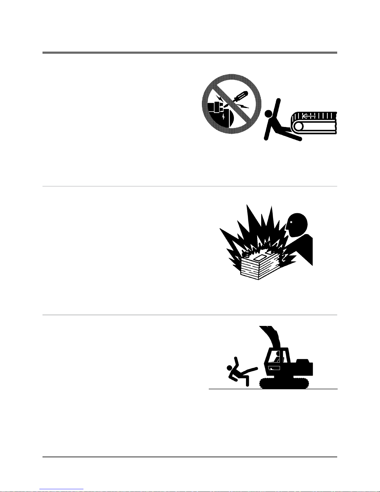
AVOID INJURY FROM ROLLAWAY ACCIDENTS
•
Death or serious injury may result if you attempt to mount
or stop a moving machine.
To avoid rollaways:
• Select level ground when possible to park the machine.
• Do not park the machine on a grade.
• Lower the bucket and/or other work tools to the ground.
• Turn the auto-idle switch OFF and the power mode switch
E or P.
• Run the engine at slow idle speed without load for 5 min
-
utes to cool down the engine.
• Stop the engine and remove the key from the key switch.
• Pull the pilot control shut-off lever to LOCK position.
• Block both tracks and lower the bucket to the ground.
Thrust the bucket teeth into the ground if you must park
on a grade.
• Position the machine to prevent rolling.
• Park a reasonable distance from other machines.
020-E02A-0493
SA-392
SA-391
Page 25
SAFETY
S-14
AVOID INJURY FROM BACK-OVER AND SWING
ACCIDENTS
•
If any person is present near the machine when backing or
swinging the upperstructure, the machine may hit or run
over that person, resulting in serious injury or death.
To avoid back-over and swing accidents:
• Always look around BEFORE YOU BACK UP AND SWING
THE MACHINE. BE SURE THAT ALL BYSTANDERS ARE
CLEAR.
• Keep the travel alarm in working condition (if equipped).
ALWAYS BE ALERT FOR BYSTANDERS MOVING INTO THE
WORK AREA. USE THE HORN OR OTHER SIGNAL TO WARN
BYSTANDERS BEFORE MOVING MACHINE.
• USE A SIGNAL PERSON WHEN BACKING UP IF YOUR VIEW
IS OBSTRUCTED. ALWAYS KEEP THE SIGNAL PERSON IN
VIEW.
Use hand signals, which conform to your local regulations,
when work conditions require a signal person.
• No machine motions shall be made unless signals are
clearly understood by both signalman and operator.
• Learn the meanings of all flags, signs, and markings used
on the job and confirm who has the responsibility for
signaling.
• Keep windows, mirrors, and lights clean and in good con
-
dition.
• Dust, heavy rain, fog, etc., can reduce visibility. As visibility
decreases, reduce speed and use proper lighting.
• Read and understand all operating instructions in the
operator’s manual.
021-E01A-0494
SA-383
SA-384
Page 26
SAFETY
S-15
KEEP PERSON CLEAR FROM WORKING AREA
•
A person may be hit severely by the swinging front attach-
ment or counterweight and/or may be crushed against an
other object, resulting in serious injury or death.
• Keep all persons clear from the area of operation and
machine movement.
• Before operating the machine, set up barriers to the sides
and rear area of the bucket swing radius to prevent anyone from entering the work area.
022-E01A-0386
NEVER POSITION BUCKET OVER ANYONE
•
Never lift, move, or swing bucket above anyone or a truck
cab.
Serious injury or machine damage may result due to bucket
load spill or due to collision with the bucket.
023-E01A-0487
AVOID UNDERCUTTING
•
In order to retreat from the edge of an excavation if the
footing should collapse, always position the undercarriage
perpendicular to the edge of the excavation with the travel
motors at the rear.
• If the footing starts to collapse and if retreat is not pos
sible, do not panic. Often, the machine can be secured by
lowering the front attachment, in such cases.
024-E01A-0488
SA-386
SA-487
SA-488
Page 27
SAFETY
S-16
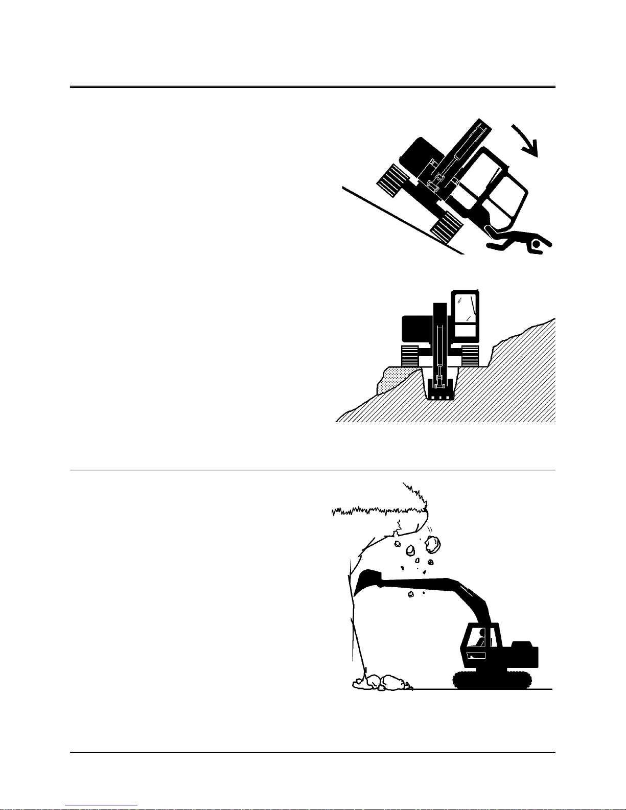
AVOID TIPPING
DO NOT ATTEMPT TO JUMP CLEAR OF TIPPING MACHINE---SERIOUS OR FATAL CRUSHING INJURIES WILL
RESULT
MACHINE WILL TIP OVER FASTER THAN YOU CAN JUMP
FREE
FASTEN YOUR SEAT BELT
•
The danger of tipping is always present when operating on
a grade, possibly resulting in serious injury or death.
To avoid tipping:
•
Be extra careful before operating on a grade.
• Prepare machine operating area flat.
• Keep the bucket low to the ground and close to the ma
-
chine.
• Reduce operating speeds to avoid tipping or slipping.
• Avoid changing direction when traveling on grades.
• NEVER attempt to travel across a grade steeper than 15
degrees if crossing the grade is unavoidable.
• Reduce swing speed as necessary when swinging loads.
•
Be careful when working on frozen ground.
• Temperature increases will cause the ground to become
soft and make ground travel unstable.
025-E03B-0463
NEVER UNDERCUT A HIGH BANK
•
The edges could collapse or a land slide could occur causing
serious injury or death.
026-E01A-0519
SA-012
SA-440
SA-489
Page 28
SAFETY
S-17
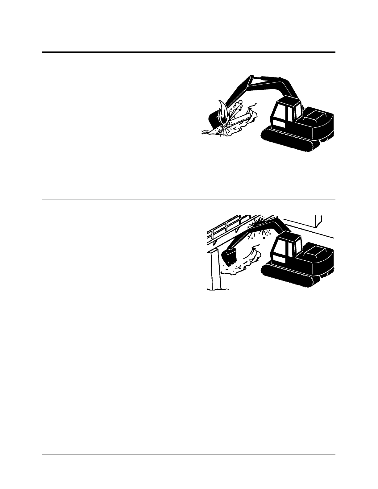
DIG WITH CAUTION
•
Accidental severing of underground cables or gas lines may
cause an explosion and/or fire, possibly resulting in serious
injury or death.
• Before digging check the location of cables, gas lines, and
water lines.
• Keep the minimum distance required, by law, from cables,
gas lines, and water lines.
• If a fiber optic cable should be accidentally severed, do
not look into the end. Doing so may result in serious eye
injury.
• Contact your local “diggers hot line” if available in your
area , and/or the utility companies directly.
Have them mark all underground utilities.
027-E01A-0382
OPERATE WITH CAUTION
•
If the front attachment or any other part of the machine hits
against an overhead obstacle, such as a bridge, both the
machine and the overhead obstacle will be damaged, and
personal injury may result as well.
• Take care to avoid hitting overhead obstacles with the
boom or arm.
028-E01A-0389
SA-382
SA-389
Page 29
SAFETY
S-18
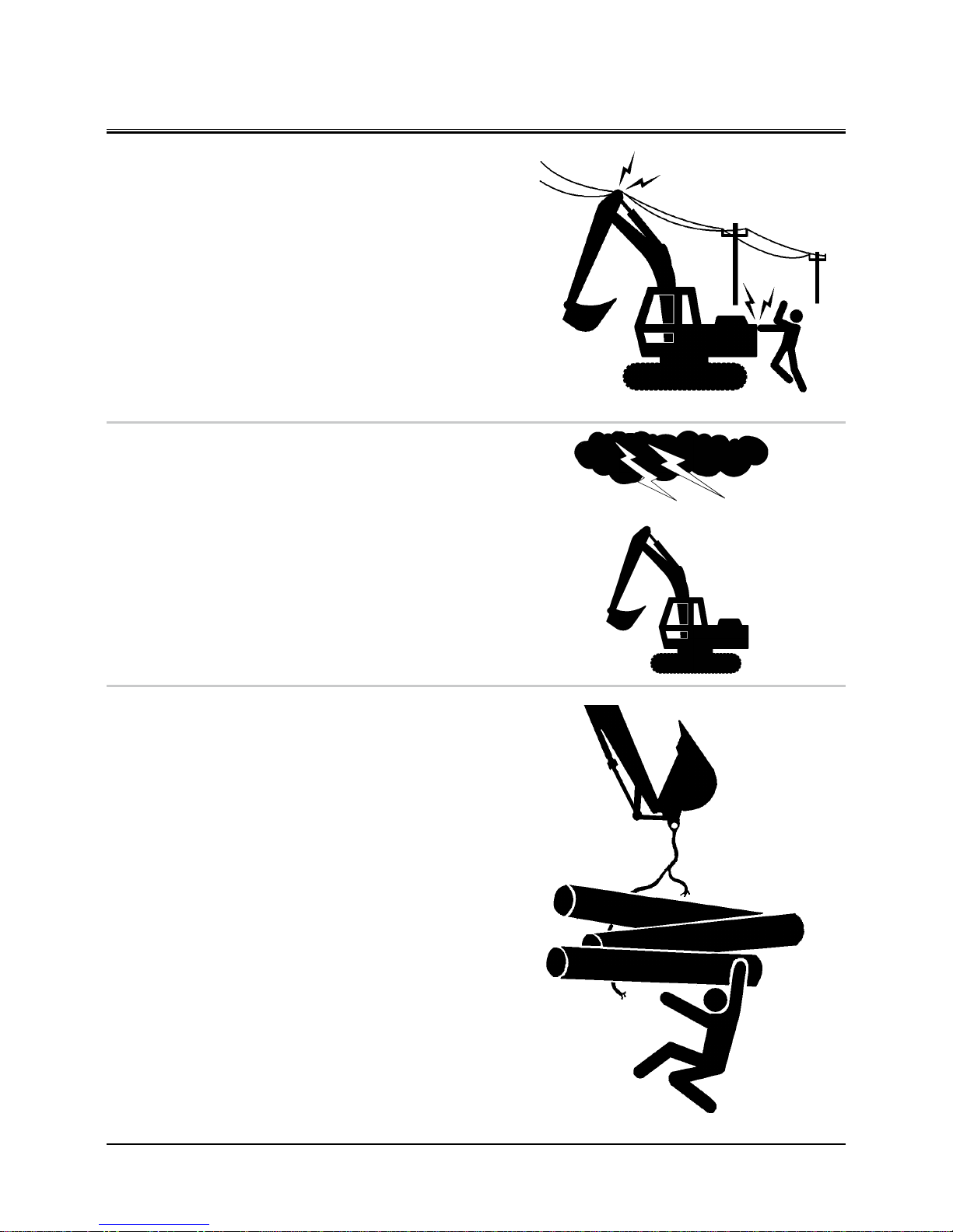
AVOID POWER LINES
•
Serious injury or death can result if the machine or front at-
tachments are not kept a safe distance from electric lines.
• When operating near an electric line, NEVER move any
part of the machine or load closer than 3 m plus twice the
line insulator length.
• Check and comply with any local regulations that may ap
-
ply.
• Wet ground will expand the area that could cause any
person on it to be affected by electric shock. Keep all
bystanders or co-workers away from the site.
029-E01A-0381
PRECAUTIONS FOR LIGHTNING
•
The machine is vulnerable to lightning strikes.
• In the event of an electrical storm, immediately stop op
eration, and lower the bucket to the ground. Evacuate to
a safe place far away from the machine.
• After the electrical storm has passed, check all of the
machine safety devices for any failure. If any failed safety
devices are found, operate the machine only after repairing them.
OBJECT HANDLING
•
If a lifted load should fall, any person nearby may be struck
by the falling load or may be crushed underneath it, resulting in serious injury or death.
• When using the machine for craning operations, be sure
to comply with all local regulations.
• Do not use damaged chains or frayed cables, sables,
slings, or ropes.
• Before craning, position the upperstructure with the travel
motors at the rear.
• Move the load slowly and carefully. Never move it sud
-
denly.
• Keep all persons well away from the load.
• Never move a load over a person’s head.
• Do not allow anyone to approach the load until it is safely
and securely situated on supporting blocks or on the
ground.
• Never attach a sling or chain to the bucket teeth. They
may come off, causing the load to fall.
032-E01A-0132
SA-381
SA-1088
SA-014
Page 30
SAFETY
S-19
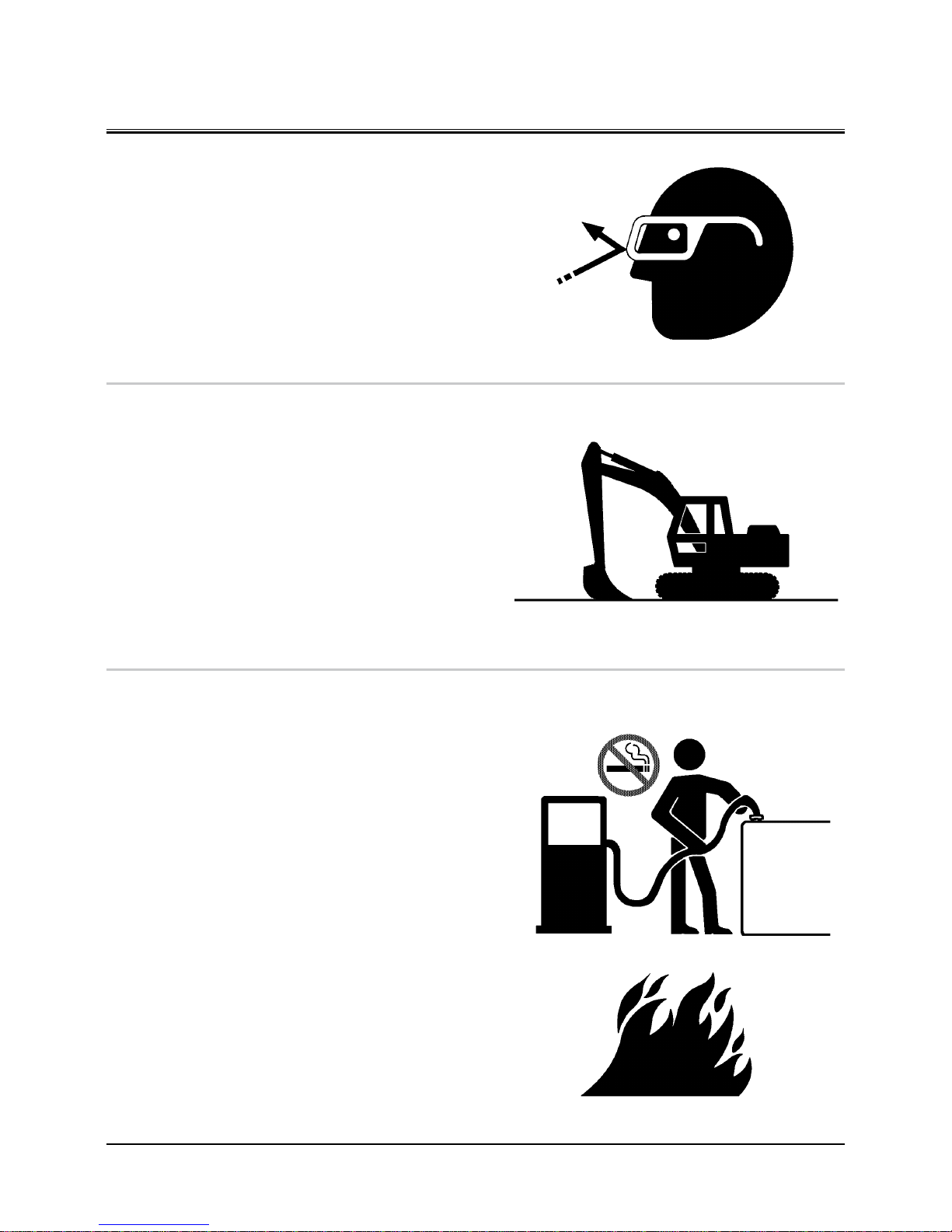
PROTECT AGAINST FLYING DEBRIS
•
If flying debris hit eyes or any other part of the body, serious
injury may result.
• Guard against injury from flying pieces of metal or debris;
wear goggles or safety glasses.
• Keep bystanders away from the working area before strik
-
ing any object.
031-E01A-0432
PARK MACHINE SAFELY
To avoid accidents:
• Park machine on a firm, level surface.
• Lower bucket to the ground.
• Turn auto-idle switch OFF and power mode switch E or P.
• Run engine at slow idle speed without load for 5 minutes.
• Turn key switch to OFF to stop engine.
• Remove the key from the key switch.
• Pull the pilot control shut-off lever to the LOCK position.
• Close windows, roof vent, and cab door.
• Lock all access doors and compartments.
HANDLE FLUIDS SAFELY−AVOID FIRES
•
Handle fuel with care; it is highly flammable. If fuel ignites,
an explosion and/or a fire may occur, possibly resulting in
serious injury or death.
• Do not refuel the machine while smoking or when near
open flame or sparks.
• Always stop the engine before refueling the machine.
• Fill the fuel tank outdoors.
•
All fuels, most lubricants, and some coolants are flammable.
• Store flammable fluids well away from fire hazards.
• Do not incinerate or puncture pressurized containers.
• Do not store oily rags; they can ignite and burn spontane
-
ously.
• Securely tighten the fuel and oil filler cap.
034-E01A-0496
SA-432
SA-390
SA-018
SA-019
Page 31

SAFETY
S-20
TRANSPORT SAFELY
•
Take care the machine may turn over when loading or un-
loading the machine onto or off of a truck or trailer.
• Observe the related regulations and rules for safe trans
-
portation.
• Select an appropriate truck or trailer for the machine to
be transported.
• Be sure to use a signal person.
• Always follow the following precautions for loading or
unloading:
1. Select solid and level ground.
2. Always use a ramp or deck strong enough to support the
machine weight.
3. Turn auto-idle switch OFF.
4. Always select the slow speed mode with the travel mode
switch.
5. Never load or unload the machine onto or off a truck or
trailer using the front attachment functions when driving
up or down the ramp.
6. Never steer the machine while on the ramp. If the travel
ing direction must be changed while the ramp, unload
the machine from the ramp, reposition the machine on
the ground, then try loading again.
7. The top end of the ramp where it meets the flatbed is a
sudden bump. Take care when traveling over it.
8. Place blocks in front of and behind the tires. Securely
hold the machine to the truck or trailer deck with wire
ropes.
Be sure to further follow the details described in the TRANSPORTING section.
035-E07A-0454
SA-395
Page 32

SAFETY
S-21
PRACTICE SAFE MAINTENANCE
To avoid accidents:
• Understand service procedures before starting work.
• Keep the work area clean and dry.
• Do not spray water or steam inside cab.
• Never lubricate or service the machine while it is moving.
• Keep hands, feet and clothing away from power-driven
parts.
Before servicing the machine:
1. Park the machine on a level surface.
2. Lower the bucket to the ground.
3. Turn the auto-idle switch off.
4. Run the engine at slow idle speed without load for 5 min
-
utes.
5. Turn the key switch to OFF to stop engine.
6. Relieve the pressure in the hydraulic system by moving
the control levers several times.
7. Remove the key from the skey witch.
8. Attach a “Do Not Operate” tag on the control lever.
9. Pull the pilot control shut-off lever to the LOCK position.
10. Allow the engine to cool.
• If a maintenance procedure must be performed with the
engine running, do not leave the machine unattended.
• If the machine must be raised, maintain a 90 to 110˚ angle
between the boom and arm. Securely support any machine elements that must be raised for service work.
• Inspect certain parts periodically and repair or replace as
necessary. Refer to the section discussing that part in the
“MAINTENANCE” chapter of this manual.
• Keep all parts in good condition and properly installed.
• Fix damage immediately. Replace worn or broken parts.
Remove any buildup of grease, oil, or debris.
• When cleaning parts, always use nonflammable detergent
oil. Never use highly flammable oil such as fuel oil and
gasoline to clean parts or surfaces.
• Disconnect battery ground cable (−) before making
adjustments to electrical systems or before performing
welding on the machine.
500-E02C-0520
SA-028
SA-527
Page 33

SAFETY
S-22
• Sufficiently illuminate the work site. Use a maintenance
work light when working under or inside the machine.
• Always use a work light protected with a guard. In case
the light bulb is broken, spilled fuel, oil, antifreeze fluid,
or window washer fluid may catch fire.
WARN OTHERS OF SERVICE WORK
•
Unexpected machine movement can cause serious injury.
• Before performing any work on the machine, attach a “Do
Not Operate” tag on the control lever.
This tag is available from your authorized dealer.
501-E01A-0287
SUPPORT MACHINE PROPERLY
•
Never attempt to work on the machine without securing
the machine first.
• Always lower the attachment to the ground before you
work on the machine.
• If you must work on a lifted machine or attachment, se
curely support the machine or attachment. Do not support the machine on cinder blocks, hollow tires, or props
that may crumble under continuous load. Do not work
under a machine that is supported solely by a jack.
519-E01A-0527
STAY CLEAR OF MOVING PARTS
•
Entanglement in moving parts can cause serious injury.
• To prevent accidents, care should be taken to ensure that
hands, feet, clothing, jewelry and hair do not become
entangled when working around rotating parts.
502-E01A-0026
SA-037
SS2045102
SA-527
SA-026
Page 34

SAFETY
S-23
PREVENT PARTS FROM FLYING
•
Grease in the track adjuster is under high pressure.
Failure to follow the precautions below may result in serious
injury, blindness, or death.
• Do not attempt to remove GREASE FITTING or VALVE AS
-
SEMBLY.
• As pieces may fly off, be sure to keep body and face away
from valve.
• Never attempt to disassemble the track adjuster. Inad
vertent disassembling of the track adjuster may cause
the parts such as a spring to fly off, possibly resulting in
severe personal injury or death.
•
Travel reduction gears are under pressure.
• As pieces may fly off, be sure to keep body and face away
from AIR RELEASE PLUG to avoid injury.
• GEAR OIL is hot. Wait for GEAR OIL to cool, then gradually
loosen AIR RELEASE PLUG to release pressure.
503-E01B-0344
STORE ATTACHMENTS SAFELY
•
Stored attachments such as buckets, hydraulic hammers,
and blades can fall and cause serious injury or death.
• Securely store attachments and implements to prevent
falling. Keep children and bystanders away from storage
areas.
504-E01A-0034
SA-344
SA-034
Page 35

SAFETY
S-24
PREVENT BURNS
Hot spraying fluids:
•
After operation, engine coolant is hot and under pressure.
Hot water or steam is contained in the engine, radiator and
heater lines.
Skin contact with escaping hot water or steam can cause
severe burns.
• To avoid possible injury from hot spraying water. DO NOT
remove the radiator cap until the engine is cool. When
opening, turn the cap slowly to the stop. Allow all pressure to be released before removing the cap.
• The hydraulic oil tank is pressurized. Again, be sure to
release all pressure before removing the cap.
Hot fluids and surfaces:
•
Engine oil, gear oil and hydraulic oil also become hot during
operation.
The engine, hoses, lines and other parts become hot as well.
• Wait for the oil and components to cool before starting
any maintenance or inspection work.
505-E01B-0498
REPLACE RUBBER HOSES PERIODICALLY
•
Rubber hoses that contain flammable fluids under pressure
may break due to aging, fatigue, and abrasion. It is very
difficult to gauge the extent of deterioration due to aging,
fatigue, and abrasion of rubber hoses by inspection alone.
• Periodically replace the rubber hoses. (See the page of
“Periodic replacement of parts” in the operator’s manual.)
•
Failure to periodically replace rubber hoses may cause a fire,
fluid injection into skin, or the front attachment to fall on a
person nearby, which may result in severe burns, gangrene,
or otherwise serious injury or death.
S506-E01A-0019
SA-039
SA-225
SA-019
Page 36

SAFETY
S-25
AVOID HIGH-PRESSURE FLUIDS
•
Fluids such as diesel fuel or hydraulic oil under pressure can
penetrate the skin or eyes causing serious injury, blindness
or death.
• Avoid this hazard by relieving pressure before disconnect
-
ing hydraulic or other lines.
• Tighten all connections before applying pressure.
• Search for leaks with a piece of cardboard; take care to
protect hands and body from high-pressure fluids. Wear a
face shield or goggles for eye protection.
• If an accident occurs, see a doctor familiar with this type
of injury immediately. Any fluid injected into the skin
must be surgically removed within a few hours or gangrene may result.
507-E03A-0499
SA-031
SA-292
SA-044
Page 37

SAFETY
S-26
PREVENT FIRES
Check for Oil Leaks:
•
Fuel, hydraulic oil and lubricant leaks can lead to fires.
• Check for oil leaks due to missing or loose clamps, kinked
hoses, lines or hoses that rub against each other, damage
to the oil-cooler, and loose oil-cooler flange bolts.
• Tighten, repair or replace any missing, loose or damaged
clamps, lines, hoses, oil-cooler and oil-cooler flange bolts.
• Do not bend or strike high-pressure lines.
• Never install bent or damaged lines, pipes, or hoses.
Check for Shorts:
•
Short circuits can cause fires.
• Clean and tighten all electrical connections.
• Check before each shift or after eight (8) to ten (10) hours
operation for loose, kinked, hardened or frayed electrical
cables and wires.
• Check before each shift or after eight (8) to ten (10) hours
operation for missing or damaged terminal caps.
• DO NOT OPERATE MACHINE if cable or wires are loose,
kinked, etc..
Clean up Flammables:
•
Spilled fuel and oil, and trash, grease, debris, accumulated
coal dust, and other flammables may cause fires.
• Prevent fires by inspecting and cleaning the machine
daily and by removing spilled or accumulated flammables
immediately.
Check Key Switch:
•
If a fire breaks out, failure to stop the engine will escalate
the fire, hampering fire fighting.
Always check key switch function before operating the ma-
chine every day:
1. Start the engine and run it at slow idle.
2. Turn the key switch to the OFF position to confirm that
the engine stops.
• If any abnormalities are found, be sure to repair them
before operating the machine.
508-E02B-0019
Check Heat Shields:
•
Damaged or missing heat shields may lead to fires.
• Damaged or missing heat shields must be repaired or
replaced before operating the machine.
508-E02A-0393
SA-019
Page 38

SAFETY
S-27
EVACUATING IN CASE OF FIRE
•
If a fire breaks out, evacuate the machine in the following
way:
• Stop the engine by turning the key switch to the OFF
position if there is time.
• Use a fire extinguisher if there is time.
• Exit the machine.
•
In an emergency, if the cab door or front window can not
be opened, break the front or rear window panes with the
emergency evacuation hammer to escape from the cab.
Refer the explanation pages on the Emergency Evacuation
Method.
18-E02B-0393
BEWARE OF EXHAUST FUMES
•
Prevent asphyxiation. Engine exhaust fumes can cause sick-
ness or death.
• If you must operate in a building, be sure there is ad
equate ventilation. Either use an exhaust pipe extension
to remove the exhaust fumes or open doors and windows
to bring enough outside air into the area.
509-E01A-0016
PRECAUTIONS FOR WELDING AND GRINDING
•
Welding may generate gas and/or small fires.
• Be sure to perform welding in a well ventilated and pre
pared area. Store flammable objects in a safe place before
starting welding.
• Only qualified personnel should perform welding.
Never allow an unqualified person to perform welding.
•
Grinding on the machine may create fire hazards. Store
flammable objects in a safe place before starting grinding.
•
After finishing welding and grinding, recheck that there are
no abnormalities such as the area surrounding the welded
area still smoldering.
523-E01A-0818
SA-393
SS-1510
SA-016
SA-818
Page 39

SAFETY
S-28
AVOID HEATING NEAR PRESSURIZED FLUID LINES
•
Flammable spray can be generated by heating near pres-
surized fluid lines, resulting in severe burns to yourself and
bystanders.
• Do not heat by welding, soldering, or using a torch near
pressurized fluid lines or other flammable materials.
• Pressurized lines can be accidentally cut when heat goes
beyond the immediate flame area. Install temporary fireresistant guards to protect hoses or other materials before
engaging in welding, soldering, etc..
AVOID APPLYING HEAT TO LINES CONTAINING
FLAMMABLE FLUIDS
• Do not weld or flame cut pipes or tubes that contain flammable fluids.
• Clean them thoroughly with nonflammable solvent be
-
fore welding or flame cutting them.
510-E01B-0030
REMOVE PAINT BEFORE WELDING OR HEATING
•
Hazardous fumes can be generated when paint is heated by
welding, soldering, or using a torch. If inhaled, these fumes
may cause sickness.
• Avoid potentially toxic fumes and dust.
• Do all such work outside or in a well-ventilated area. Dis
-
pose of paint and solvent properly.
• Remove paint before welding or heating:
1. If you sand or grind paint, avoid breathing the dust.
Wear an approved respirator.
2. If you use solvent or paint stripper, remove stripper with
soap and water before welding. Remove solvent or paint
stripper containers and other flammable material from
area. Allow fumes to disperse at least 15 minutes before
welding or heating.
511-E01A-0029
SA-030
SA-029
Page 40

SAFETY
S-29
BEWARE OF ASBESTOS DUST
•
Take care not to inhale dust produced in the work site. Inha-
lation of asbestos fibers may be the cause of lung cancer.
• Depending on the wok site conditions, the risk of inhaling
asbestos fiber may exist. Spray water to prevent asbestos
from becoming airborne. Do not use compressed air.
• When operating the machine in a work site where asbes
tos might be present, be sure to operate the machine
from the upwind side and wear a mask rated to prevent
the inhalation of asbestos.
• Keep bystanders out of the work site during operation.
• Asbestos might be present in imitation parts. Use only
genuine Hitachi Parts.
PREVENT BATTERY EXPLOSIONS
•
Battery gas can explode.
• Keep sparks, lighted matches, and flame away from the
top of battery.
• Never check battery charge by placing a metal object
across the posts. Use a voltmeter or hydrometer.
• Do not charge a frozen battery; it may explode. Warm the
battery to 16 ˚C ( 60 ˚F ) first.
• Do not continue to use or charge the battery when elec
trolyte level is lower than specified. Explosion of the battery may result.
• Loose terminals may produce sparks. Securely tighten all
terminals.
•
Battery electrolyte is poisonous. If the battery should ex-
plode, battery electrolyte may be splashed into eyes, possibly resulting in blindness.
• Be sure to wear eye protection when checking electrolyte
specific gravity.
512-E01B-0032
SERVICE AIR CONDITIONING SYSTEM SAFELY
•
If spilled onto skin, refrigerant may cause a cold contact
burn.
• Refer to the instructions described on the container for
proper use when handling the refrigerant.
• Use a recovery and recycling system to avoid leaking
refrigerant into the atmosphere.
• Never touch the refrigerant.
513-E01A-0405
SA-029
SA-032
SA-405
Page 41

SAFETY
S-30
HANDLE CHEMICAL PRODUCTS SAFELY
•
Direct exposure to hazardous chemicals can cause serious
injury. Potentially hazardous chemicals used with your machine include such items as lubricants, coolants, paints, and
adhesives.
• A Material Safety Data Sheet (MSDS) provides specific de
tails on chemical products: physical and health hazards,
safety procedures, and emergency response techniques.
• Check the MSDS before you start any job using a hazard
ous chemical. That way you will know exactly what the
risks are and how to do the job safely. Then follow procedures and use recommended equipment.
• See your authorized dealer for MSDS’s (available only in
English) on chemical products used with your machine.
515-E01A-0309
DISPOSE OF WASTE PROPERLY
•
Improperly disposing of waste can threaten the environ-
ment and ecology. Potentially harmful waste used with
HITACHI equipment includes such items as oil, fuel, coolant,
brake fluid, filters, and batteries.
• Use leakproof containers when draining fluids. Do not use
food or beverage containers that may mislead someone
into drinking from them.
• Do not pour waste onto the ground, down a drain, or into
any water source.
• Air conditioning refrigerants escaping into the air can
damage the Earth’s atmosphere. Government regulations
may require a certified air conditioning service center to
recover and recycle used air conditioning refrigerants.
• Inquire on the proper way to recycle or dispose of waste
from your local environmental or recycling center, or from
your authorized dealer.
516-E01A-0226
SA-309
SA-226
Page 42

SAFETY SIGNS/Europe/Asia/Middle and Near East Model Only
S-31
All safety signs and their locations affixed on the machine are
illustrated in this group. Make sure of the contents described
in the safety signs through reading actual ones affixed on the
machine to ensure safe machine operation. Always keep the
safety signs clean. In case a safety sign is broken or lost, immediately, obtain a new replacement and affix it again in position
on the machine. Use the part No. indicated under the right
corner of each safety sign illustration when placing an order of
it to the Hitachi dealer.
1
10
2
6
3
4
18A
11
17
16
13
8
RIGHT WINDOW
19
5
ZX180-3 class
ZX120-3 class
ZX200-3, 270-3,
330-3 class
15
14
15
12B
7
18B
18C
12A
18
SS-3033
Page 43

SAFETY SIGNS/Europe/Asia/Middle and Near East Model Only
S-32
1.
WARNING!
Prior to operation, maintenance, disassembling, and trans
portation of the machine, be sure to read and understand
the Operator’s Manual.
2.
If the parked machine is unexpectedly moved, serious injury
or death due to crushing may result. Be sure to lower the
front attachment to the ground, lock the control levers, and
remove the engine key before leaving the machine unattended.
3.
Sign indicates an electrocution hazard if machine is brought
too near electric power lines.
Keep a safe distance from electric power lines.
4.
Sign indicates a hazard from falling window.
After raising window, be sure to lock it in place with lock
pins.
SS4420333
SS4420332
SS4420335
SS4420334
Page 44

SAFETY SIGNS/Europe/Asia/Middle and Near East Model Only
S-33
5.
When moving the seat height/tilt lever downward, press the
lever grip with a palm from the top side. Do not grasp the
lever grip to operate the lever, possibly resulting in pinch of
your fingers into the seat stand.
6.
If the machine should overturn, the operator may become
injured and/or throw from the cab and/or crushed by the
overturning machine.
7.
When operating with 2-piece boom, the bucket may come
in contact with the cab. Operate the machine with care not
to allow the tip of the bucket to hit the cab while rolling in
the front attachment.
8.
Do not extend your hands or head from the window. Your
hands or head may come in contact with the boom.
Keep away from machine during operation.
SS4603204
SS4654287
SS4459990
SS4371371
Page 45

SAFETY SIGNS/Europe/Asia/Middle and Near East Model Only
S-34
9.
10.
Sign indicates a hazard of being hit by the working device
of the machine.
Keep away from machine during operation.
11.
Sign indicates a hazard of a flying plug from track adjuster
that could cause injury.
Read manual before adjusting track for safe and proper handling.
SS3106039
SS3089581
SS3086091
Page 46

SAFETY SIGNS/Europe/Asia/Middle and Near East Model Only
S-35
12.
Sign indicates a burn hazard from compressed air and spurting hot oil if the oil inlet is uncapped during or right after
operation.
Read manual for safe and proper handling.
Sign indicates a burn hazard from spurting hot water or oil if
radiator or hydraulic oil tank is uncapped while hot.
Allow radiator or hydraulic oil tank to cool before removing
cap.
13.
Sign indicates a hazard of falling.
Do not stand on this place.
14.
Sign indicates a hazard of falling off the fender or hood.
Never stand close to the edge.
SS3092125
SS4459928
A
B
SS4420336
SS3092126
Page 47

SAFETY SIGNS/Europe/Asia/Middle and Near East Model Only
S-36
15.
Sign indicates a crush hazard by rotation of upper structure
of the machine.
Keep away from swinging area of machine.
16.
Sign indicates a burn hazard from spurting hot water or oil if
radiator or hydraulic oil tank is uncapped while hot.
Allow radiator or hydraulic oil tank to cool before removing
cap.
17.
Sign indicates a hazard of rotating parts, such as belt.
Turn off before inspection and maintenance.
SS4420336
SS3092127
SS3086090
Page 48

SAFETY SIGNS/Europe/Asia/Middle and Near East Model Only
S-37
18.
Sign indicates an electrical hazard from handling the cable.
Read manual for safe and proper handling.
Sign indicates an explosion hazard.
Keep fire and open flames away from this area.
Skin contact with electrolyte will cause burns. Splashed
electrolyte into eyes will cause blindness. Take care not to
touch electrolyte.
19.
SS4459714
SS4467093
C
A
B
SS4460067
SS4460056
Page 49

SAFETY SIGNS/Europe/Asia/Middle and Near East Model Only
S-38
MEMO
...................................................................................................................................................................................................................................................
...................................................................................................................................................................................................................................................
...................................................................................................................................................................................................................................................
...................................................................................................................................................................................................................................................
...................................................................................................................................................................................................................................................
...................................................................................................................................................................................................................................................
...................................................................................................................................................................................................................................................
...................................................................................................................................................................................................................................................
...................................................................................................................................................................................................................................................
...................................................................................................................................................................................................................................................
...................................................................................................................................................................................................................................................
...................................................................................................................................................................................................................................................
...................................................................................................................................................................................................................................................
...................................................................................................................................................................................................................................................
...................................................................................................................................................................................................................................................
...................................................................................................................................................................................................................................................
...................................................................................................................................................................................................................................................
...................................................................................................................................................................................................................................................
...................................................................................................................................................................................................................................................
...................................................................................................................................................................................................................................................
...................................................................................................................................................................................................................................................
...................................................................................................................................................................................................................................................
...................................................................................................................................................................................................................................................
...................................................................................................................................................................................................................................................
...................................................................................................................................................................................................................................................
...................................................................................................................................................................................................................................................
...................................................................................................................................................................................................................................................
...................................................................................................................................................................................................................................................
...................................................................................................................................................................................................................................................
...................................................................................................................................................................................................................................................
...................................................................................................................................................................................................................................................
...................................................................................................................................................................................................................................................
...................................................................................................................................................................................................................................................
...................................................................................................................................................................................................................................................
...................................................................................................................................................................................................................................................
...................................................................................................................................................................................................................................................
...................................................................................................................................................................................................................................................
Page 50

OPERATOR'S STATION
1-1
COMPONENTS NAME
COMPONENTS NAME
1- Bucket
2- Bucket Cylinder
3- Arm
4- Arm Cylinder
5- Boom Cylinder
6- Boom
7- Fuel Tank
8- Hydraulic Oil Tank
9- Engine
10- Counterweight
11- Travel Device
12- Track
13- Front Idler
14- Cab
3
2
1
4
5
6
7
8
9
10
11
12
13
14
M1U1-01-005
Page 51

OPERATOR'S STATION
1-2
CAB FEATURES
Std. Model
1- Left Control Lever/Horn Switch
(On Top of Lever)
2- Left Travel Pedal
3- Left Travel Lever
4- Right Travel Lever
5- Right Travel Pedal
6- Attachment Pedal (Optional)
7- Right Control Lever/Power Boost Switch
(Except ZX120-3 class)
8- Multi Function Monitor Panel
9- Switch Panel
10- Key Switch
11- Air Conditioner Panel
12- Radio
13- Operator's Seat
14- Cab Door Release Lever
15- Pilot Control Shut-Off Lever
16- Glove Compartment
17- Fuse Box
18- Cigar Lighter
19- Switch Panel
20- Hot & Cool Box
21- Engine Stop Switch
M1U1-01-002
M1U1-01-029
21
19
18
17
16
20
1 2 3 4 5 6 7
12
11
10
9
8
14
15
13
M1J1-01-026
Page 52

OPERATOR'S STATION
1-3
MULTI FUNCTION MONITOR
How To Use Screens
Displaying Basic Screen
IMPORTANT: Start the engine after the basic screen is
displayed.
When the key switch is turned to the ON position, the starting
screen displays for about two seconds and the basic screen
displays.
IMPORTANT: After the engine starts and the alternator
starts generating power, alternator alarm is
displayed on the basic screen.
T1V1-05-01-115
T1V1-05-01-123
T1V1-05-01-117
Key Switch: ON
Basic Screen
Alternator Alarm
Page 53

OPERATOR'S STATION
1-4
OUTLINE
1 - Work Mode Display
2 - Auto-Idle Display
3 - Overload Alarm Display
(Optional)
4 - Auxiliary
5 - Auxiliary
6 - Preheat Display
7 - Work Mode Display
8 - Hour Meter
9 - Auxiliary
10 - Fuel Gauge
11 - Mail Display (Optional)
12 - Auxiliary
13 - Fuel Rate Display
14 - Clock
15 - Back Monitor Selector (Optional)
16 - Menu
17 - Auxiliary Selection
18 - Mail Selection (Optional)
19 - Auxiliary Selection (Optional)
20 - Work Mode Selection
21 - Return to Basic Screen Key
22 - Coolant Temperature Gauge
1
2
4 5 6 7 8
3
22
9
10
11
12
13
14
15
161718192021
M1U1-01-111
Page 54

OPERATOR'S STATION
1-5
Work Mode
8
10
14
16
22
M1U1-01-112
•
Display of Meters
Items to be displayed
8. Hour Meter
10. Fuel Gauge
14. Clock
16. Menu
22. Coolant Temperature Gauge
•
Work Mode Display
The attachments being used are displayed.
Digging mode
T1V1-05-01-108
Attachment mode
Breaker
T1V1-05-01-104
Pulverizer
T1V1-05-01-105
Crusher
T1V1-05-01-106
Vibration hammer
T1V1-05-01-107
Other
T1V1-05-02-003
Page 55

OPERATOR'S STATION
1-6
•
Auto-Idle Display (2)
When selecting auto-idle from the switch panel, auto-idle
display (2) is displayed.
When the key is turned ON, the data blinks for 10 seconds.
Overload Alarm Display (3) (optional)
T1V1-05-02-002
The system measures the load of suspended load from the
bottom pressure of boom cylinder. When overload is detected, an alarm is displayed.
•
Preheat Display (6)
While the current is being supplied to the glow plug, the
indicator is displayed.
•
Fuel Rate Display (13)
Fuel consumption is displayed (Reference value).
2 6
13
3
M1U1-01-113
Page 56

OPERATOR'S STATION
1-7
Menu Screen (23)
Press menu key (16) on the basic screen to display main menu
screen (23). Select the desired menu by operating key (25)
located under keys on icon display area (24).
23
24
25
16
T1V5-05-01-019
Page 57

OPERATOR'S STATION
1-8
Hour Meter
Total (accumulated) machine operation hours counted since
the machine started working, are displayed in the unit of HOUR
(h). One digit after the decimal point indicates the tenths of an
hour (6 minutes).
Fuel Gauge
The fuel amount in the fuel tank is indicated. Refuel before the
needle reaches “E”.
Clock
Indicates the present time.
Back Monitor Selector
Shifts the monitor screen to the back view monitor screen and
vice versa.
M1U1-01-039
M81U-01-058
M1U1-01-041
M1U1-01-040
Page 58

OPERATOR'S STATION
1-9
Menu Key
Shifts the basic screen to the menu screen.
Optional Function Key
The desired preset optional function can be selected by operating these keys even though the menu key is not operated.
F1 : Work Mode Selection
F2 : Auxiliary
F3 : Mail (Optional)
F4 : Auxiliary
are the fixed function keys.
Return to Basic Screen Key
Allows any screen to return to the basic screen.
Alarm Light
Comes ON when any abnormality occurs.
Optional Function Display
Displays the optional functions preset by the optional function
key.
F1 : Work Mode Selection
F2 : Auxiliary
F3 : Mail (Optional)
F4 : Auxiliary
M1U1-01-042
M1U1-01-043
M1U1-01-044
M1U1-01-045
M1U1-01-114
Page 59

OPERATOR'S STATION
1-10
Coolant Temperature Gauge
Indicates the engine coolant temperature. Normally the needle
is around the center of the scale during operation.
Operating Status Icon Display
Displays icons indicating the current status of the attachment
(1) selected at the work mode selection screen and operation
modes such as the auto-idle system (2) and preheat display (3),
etc when these systems are activated.
1 2 3
M1U1-01-065
M1U1-01-047
Page 60

OPERATOR'S STATION
1-11
Displaying Basic Screen by Password Input (Optional)
IMPORTANT: When required to activate the TEN-key func
tion (ignition block system), consult your
nearest Hitachi dealer.
If the password ever escapes the customer’s
memory, the machine must be modified. Be
extra careful not to forget the password.
1. Turn the key switch ON. After the starting screen is dis
-
played, the password input screen will be displayed.
2. Input a password by using the keys located under the
screen. If pushing the determination key, the monitor
unit matches the input password to the registered one. If
they match, the basic screen displays.
NOTE: When inputting the password again, the entered char-
acters can be erased by pushing the delete key.
Starting Screen
Password Input Screen
Basic Screen
Determination Key
Delete Key
T1V1-05-01-115
T1V5-05-01-093
T1V5-05-01-002
T1V1-05-01-123
Page 61

OPERATOR'S STATION
1-12
In Case of Inputting an Incorrect Password
1. If inputting an incorrect password, the message “Pass
word is incorrect.” displays by pushing the determination
key.
2. Return to the password input screen, by pushing the
back key.
NOTE: When inputting the password again, the entered char-
acters can be erased by pushing the delete key.
Back key
T1V5-05-01-004
T1V5-05-01-093
Determination Key
Delete Key
T1V5-05-01-002
T1V5-05-01-093
Password Input Screen
Page 62

OPERATOR'S STATION
1-13
3. If inputting an incorrect password three times, a screen
displays informing that the security lock has been applied, and a buzzer rings for thirty seconds. During that
time, the buzzer does not stop ringing even if turning of
the key switch ON/OFF.
4. After thirty seconds, if the key switch is turned to the ON
position, the starting screen displays and the password
input screen displays again. Then a password can be
input again. If inputting an incorrect password even once
this time, the security lock screen displays again and a
buzzer rings for thirty seconds. The buzzer does not stop
ringing for thirty seconds even if turning the key switch
ON/OFF.
5. After the buzzer stops ringing, a password can be input
again. Turn the key switch to the ON position and input a
password after the password input screen displays. (Refer
to page 1-12)
6. If inputting an incorrect password again, the security lock
screen displays again. The buzzer does not stop ringing
for thirty seconds even if turning the key switch ON/OFF.
T1V1-05-01-115
T1V5-05-01-093
T1V5-05-01-005
Security Lock Screen
Starting Screen
Password Input Screen
Page 63

OPERATOR'S STATION
1-14
Extending Password Duration Time
IMPORTANT: This operation is applicable only to those
machines that display the basic screen based
upon password input.
By using the password duration screen, password duration
time can be set. When you restarting the machine, a password need not be input within that timeframe.
1. When turn the key switch to the OFF position, the monitor unit displays the password duration screen for ten
seconds.
2. While the password duration screen is still displayed,
push a relevant key, and password duration time is set.
Duration time assigned to each key is as follows:
key 1: 0 minute
key 2: 30 minutes
key 3: 60 minutes
key 4: 90 minutes
key 5: 120 minutes
NOTE: If password duration time is not set explicitly, 0 minute
on duration time is assumed.
3. If turning the key switch to the ON position within password duration time, the monitor unit displays the basic
screen after the starting screen.
Key 1
Key2
Key3 Key4
Key5
T1V1-05-01-115
Key Switch: ON
T1V1-05-01-123
Basic Screen
Password Duration Screen (Key Switch: OFF)
T1V1-05-01-012
Page 64

OPERATOR'S STATION
1-15
ALARM OCCURRENCE SCREEN
In case any abnormality occurs, alarm marks (1) are displayed
on the basic screen.
•
When the number of alarms is two or less
•
When the number of alarms is three or more
T1V1-05-01-096
T1V1-05-01-095
1
1
Page 65

OPERATOR'S STATION
1-16
In case any abnormality occurs, push the key located under the
alarm mark. The monitor displays the corrective action to the
alarm situation.
Push a Relevant Key
T1V1-05-01-095
T1V5-05-01-013
Page 66

OPERATOR'S STATION
1-17
CONTENTS OF ALARMS
Display Contents of Alarms Remedy
M178-01-036
Overheat Alarm Engine coolant temperature has abnormally increased.
Stop operation. Run the engine at slow idle speed and lower the coolant temperature.
M183-01-080
Engine Warning Alarm Engine or engine related parts are abnormal.
Consult your nearest Hitachi dealer.
M178-01-037
Engine Oil Pressure Alarm Engine oil pressure has decreased. Immediately stop engine. Check
engine oil system and oil level.
M183-01-071
Alternator Alarm Electrical system is abnormal.
Consult your nearest Hitachi dealer.
M178-01-034
Remaining Fuel Alarm Fuel level is low. Refill fuel as soon as possible.
M1CC-01-039
Hydraulic Oil Filter Alarm Hydraulic oil filter is clogged. Replace filter.
M183-01-067
Air Filter Clogged Alarm Air filter elements are clogged.
Clean or replace air filter elements.
M1U1-01-116
Fuel Filter Clogged Alarm Fuel filter elements (pre-filter, main filter) are clogged.
Replace fuel filter elements.
T1V1-05-01-102
Work Mode Alarm Work Mode system is abnormal.
Consult your nearest Hitachi dealer.
T1V1-05-01-103
Pilot Control Shut-Off Lever
Alarm
Pilot control shut-off lever system is abnormal.
Consult your nearest Hitachi dealer.
Page 67

OPERATOR'S STATION
1-18
•
Fuel Sensor Error Display
When the fuel sensor is faulty or if the harness between
fuel sensor and monitor unit is broken, the fuel sensor error
display is displayed on the fuel gauge.
•
Coolant Temperature Sensor Error Display
When the coolant temperature sensor is faulty or if the harness between coolant temperature sensor and monitor unit
is broken, the coolant temperature sensor error display is
displayed on the coolant temperature gauge.
Coolant Temperature
Sensor Error Display
Fuel Sensor Error
Display
T1V1-05-02-005
Page 68

OPERATOR'S STATION
1-19
CLOCK SETTING
Press menu key (2) on basic screen (1) to display main menu
screen (3).
Select time set menu (4) by pressing the key located under
keys on icon display area and adjust the clock set.
Time Adjustment
After selecting time set menu (4) by pressing the key located under
keys on icon display area, press determi-
nation key (5).
1. While pressing the key located under
and
keys on icon display area on time setting screen (6), select
the figures for Year, Month, Day, and Time.
2. After moving the cursor to
position (7) by pressing
the key located under key, press determination key
(5) to define the setting.
1
2
5
3
4
5
6
7
T1V1-05-01-123
T1V5-05-01-019
T1V5-05-01-021
T1V5-05-01-022
Page 69

OPERATOR'S STATION
1-20
ATTACHMENT SELECTION
(Only Machines Equipped with Optional Parts)
IMPORTANT: Select the attachments from the work mode
screen.
In order to display the work mode screen,
push work mode selection key F1 after basic
screen displays, or select from main menu.
Selecting an Attachment by Using Work Mode Selection
Key F1
1. When the basic screen displays, push work mode selec
-
tion key F1 and display the work mode screen.
2. Push a key located under an attachment mark to be used
in order to select the attachment.
(In the right example, Crusher 1 is selected.)
NOTE: When selecting Digging, return to the basic screen.
3. On the attachment specification screen, confirm if speci
fication of the installed attachment agrees with that
displayed on the screen.
NOTE: When pushing the back key, return to the previous
screen.
4. Push the determination key, and the basic screen displays.
Key F1
Back Key
Back Key
Determination
key
Digging
Select Crusher 1
T1V1-05-01-123
T1V5-05-01-109
T1V5-05-01-028
Basic Screen
Work Mode Screen
Attachment Specification Screen
Page 70

OPERATOR'S STATION
1-21
Selecting an Attachment from Main Menu
1. When the basic screen displays, push the menu key and
display main menu.
2. Select work mode from main menu by using keys 1
and 2 . Push determination key. Then, the work mode
screen displays.
3. Push the key located under an attachment mark to be
used in order to select the attachment.
(In the right example, Crusher 1 is selected.)
NOTE: When selecting Digging, return to Main Menu.
4. On the attachment specification screen, confirm if specification of the installed attachment agrees with that
displayed on the screen.
NOTE: When pushing the back key, return to the basic screen.
5. Push the determination key, and the basic screen displays.
Menu Key
Back Key
Determination KeyKey 2Key 1
Back Key
Select Crusher 1
Digging
Back Key
Determination
key
T1V1-05-01-123
Basic Screen
T1V5-05-01-109
Work Mode Screen
T1V5-05-01-028
T1V5-05-01-019
Attachment Specification Screen
Page 71

OPERATOR'S STATION
1-22
Attachment Specification Screen
Breaker 1
Breaker 2
Maximum Pump 2 Flow Rate
Maximum Engine Speed
Accumulator Control Solenoid Valve: OFF
Secondary Relief Selector Control Solenoid
Valve: ON
Three way Valve Control Solenoid Valve: ON
The three way val ve is conn ecte d to the
hydraulic oil tank.
Auxiliary Flow Combining Sole noid Valve:
OFF
Maximum Pump 2 Flow Rate
Maximum Engine Speed
Accumulator Control Solenoid Valve: ON
Secondary Relief Selector Control Solenoid
Valve: OFF
Three way Valve Control Solenoid Valve: ON
The three way val ve is conn ecte d to the
hydraulic oil tank.
Auxiliary Flow Combining Sole noid Valve:
OFF
T1V5-05-01-001
T1V5-05-01-006
Page 72

OPERATOR'S STATION
1-23
Pulverizer 1
Crusher 1
Maximum Pump 1 and 2 Flow Rate
Maximum Engine Speed
Accumulator Control Solenoid Valve: OFF
Secondary Relief Selector Control Solenoid
Valve: OFF
Three way Valve Control Solenoid Valve: OFF
The thre e way va lve is connect ed to the
control valve.
Auxiliary Flow Combining Solenoid Valve: ON
Maximum Pump 1 and 2 Flow Rate
Maximum Engine Speed
Accumulator Control Solenoid Valve: OFF
Secondary Relief Selector Control Solenoid
Valve: OFF
Three way Valve Control Solenoid Valve: OFF
The thre e way va lve is connect ed to the
control valve.
Auxiliary Flow Combining Solenoid Valve: ON
T1V5-05-01-011
T1V5-05-01-028
Page 73

OPERATOR'S STATION
1-24
PUMP 2 FLOW RATE ADJUSTMENT
(Only Machines Equipped with Optional Parts)
IMPORTANT: This operation is effective when attachments
are used.
1. When the basic screen displays, push the menu key and
display main menu.
2. Select attachment adjustment from main menu by using
keys 1 and 2 . Push determination key. Then, the
attachment adjustment screen for currently installed attachment displays.
3. Adjust flow rate of Pump 2 by using keys 1
and 2 .
When using breaker 1 or breaker 2, pushing key 1
will
decrease flow rate of pump 2 and pushing key 2 will
increase respectively.
When using the pulverizer or crusher, pushing key 1
will increase flow rate of boom raise, arm roll-out, swing
or travel circuit.
Pushing key 2
will increase flow rate of attachment
side.
NOTE: When pushing the back key, return to the previous
screen.
4. Push key 6 , and the basic screen displays.
Back KeyKey 2Key 1
Back KeyKey 2Key 1 Key 6
Menu Key
Determination KeyKey 2Key 1
T1V1-05-01-123
Basic Screen
T1V5-05-01-019
T1V5-05-01-111
T1V5-05-01-024
Page 74

OPERATOR'S STATION
1-25
DISPLAYING OPERATING CONDITIONS
1. When the basic screen displayed, push the menu key and
display main menu.
2. Select operating conditions from main menu by using
keys 1 and 2. Push the determination key. Then, the operating conditions screen displays.
3. Push the reset key, and display the data reset confirm
screen.
When reset the data, push the determination key.
NOTE: When pushing the back key, return to the previous
screen.
IMPORTANT: Total fuel consumption and fuel consump-
tion rate depend on the operating environment and the operation method of machine.
The values shown on the screen are just for
reference.
There could arise ± 20% of differences between actual fuel consumption and fuel consumption which is displayed by the monitor
unit.
4. Push key 6 , and the basic screen displays.
Back KeyReset Key
Back Key
Determination KeyKey 6
Menu Key
Determination KeyKey 2Key 1
T1V1-05-01-123
Basic Screen
T1V5-05-01-019
T1V5-05-01-025
T1V5-05-01-026
Page 75

OPERATOR'S STATION
1-26
T1V1-05-01-123
FUEL RATE DISPLAY/NO DISPLAY
Fuel Rate Display
1. When the basic screen displays, push the menu key and
display main menu.
2. Select fuel rate display/No display from main menu by
using keys 1 and 2. Push the determination key. Then, the
fuel rate display/No display screen displays.
3. Push the determination key, and fuel rate display will be
set to ON.
NOTE: When pushing the back key, return to the previous
screen.
Back Key
Back Key
Menu Key
Basic Screen
T1V5-05-01-118
T1V5-05-01-164
T1V5-05-01-119
Determination KeyKey 2Key 1
Back KeyDetermination Key
Page 76

OPERATOR'S STATION
1-27
4. Push key 6 , and the fuel rate display will be added to
basic screen.
Key 6
Fuel Rate
T1V5-05-01-119
T1V1-05-01-007
Page 77

OPERATOR'S STATION
1-28
Basic Screen
Fuel Rate No Display
1. When the basic screen displays, push the menu key and
display main menu.
2. Select fuel rate display/No display from main menu by
using keys 1 and 2 . Push the determination key.
Then, the fuel rate display/No display screen displays.
3. Push the determination key, and fuel rate display will be
set to OFF.
NOTE: When pushing the back key, return to the previous
screen.
Determination KeyKey 1 Key 2
Back Key
Back Key
Determination Key
Fuel Rate
Menu Key
T1V1-05-01-007
T1V5-05-01-118
T1V5-05-01-119
T1V5-05-01-164
Back Key
Page 78

OPERATOR'S STATION
1-29
4. Push key 6 , and return to the basic screen.
Key 6
T1V5-05-01-164
T1V1-05-01-123
Basic Screen
Page 79

OPERATOR'S STATION
1-30
•
Overload Alarm
(Only machines equipped with optional parts)
IMPORTANT: When using overload alarm, consult your
nearest Hitachi dealer.
When the overload alarm switch is turned ON, the system
measures load of the suspended load from bottom pressure of
the boom cylinder. An alarm message is displayed and buzzer
is rung, if overload is detected.
Overload Alarm Switch
T1V1-05-01-128
Basic Screen
T1V1-05-02-004
Page 80

OPERATOR'S STATION
1-31
Password Change (Optional)
1. After the basic screen is displayed, push the menu key in
order to display the main menu.
2. Select password change from main menu by using keys
1 and 2. Push the determination key. Then, the password
change screen displays.
3. Input the registered password and push the determina
-
tion key.
4. If inputting the password again, the entered characters
can be erased by pushing the delete key.
Menu Key
Determination Key
Key 1 Key 2
Delete Key
Determination Key
Registered Password
T1V1-05-01-123
Basic Screen
T1V5-05-01-129
T1V5-05-01-041
T1V5-05-01-042
Page 81

OPERATOR'S STATION
1-32
NOTE: If inputting an incorrect password after pushing the
determination key, the message “Password is incorrect.”
displays.
Push the back key and go back to the previous screen,
input the password again.
5. The message “Enter password to be registered.” displays.
Then, input a new password with three or four digits and
push the determination key.
6. If inputting the password again, push the delete key.
Back Key
Delete KeyDetermination Key
A New Password
T1V5-05-01-044
T1V5-05-01-130
T1V5-05-01-131
Page 82

OPERATOR'S STATION
1-33
7. The message “Re-enter password.” displays. Then, input a
new password again and push the determination key.
8. If inputting the password again, push the delete key in
order to delete the entered characters.
9. The message “New password has been registered.” dis
-
plays. This completes the password change process.
10. Push key 6
and the basic screen displays.
Key 6
T1V1-05-01-123
Basic Screen
T1V5-05-01-132
T1V5-05-01-133
T1V5-05-01-043
Delete KeyDetermination Key
Page 83

OPERATOR'S STATION
1-34
BACK MONITOR SETTINGS
IMPORTANT: The image displayed on the back monitor is
to be used as an assist view. Drive the machine while paying thorough attention to
the surroundings.
Auto-Control: ON
Image on the monitor unit when traveling is automatically
switched to that of the back monitor.
1. When the basic screen displays, push the menu key and
display main menu.
2. Select back monitor settings from main menu by using
keys 1 and 2 . Push the determination key. Then,
the back monitor settings screen displays.
3. Push the determination key. Then, auto-control is set to
ON.
NOTE: When pushing the back key, return to the basic screen.
4. Push key 6 , and return to the basic screen.
5. If travel operation is done, backward image is displayed
on the screen of monitor unit.
Back KeyKey 6
Menu Key
T1V1-05-01-123
Basic Screen
T1V5-05-01-174
T1V5-05-01-114
T1V5-05-01-173
Back KeyDetermination KeyKey 2Key 1
Back KeyDetermination KeyKey 2Key 1
Page 84

OPERATOR'S STATION
1-35
Auto-Control: OFF
Set automatic switching function of images between monitor unit and back monitor when traveling to OFF.
1. When the basic screen displays, push the menu key and
display main menu.
2. Select back monitor settings from main menu by using
keys 1 and 2. Push the determination key. Then, the back
monitor settings screen displays.
3. Push the determination key. Then, auto-control is set to
OFF.
NOTE: When pushing the back key, return to the previous
screen.
4. Push key 6 , and return to the basic screen.
Key 6
Menu Key
T1V1-05-01-123
Basic Screen
T1V5-05-01-173
Back Key
T1V5-05-01-174
Back KeyDetermination KeyKey 2Key 1
T1V5-05-01-118
Back KeyDetermination KeyKey 2Key 1
Page 85

OPERATOR'S STATION
1-36
MAINTENANCE SETTINGS
1. When the basic screen displays, push the menu key and
display main menu.
2. Select maintenance settings from main menu by using
keys 1 and 2 . Push the determination key. Then,
the maintenance settings screen displays.
3. Select an item to be set from among the list of mainte
nance settings screen by using keys 1 and 2 . Push
the determination key. Then, the Interval ON/OFF settings screen displays.
(In the right example, Engine Oil is selected.)
Maintenance Information Display ON/OFF
1. Select ON or OFF for maintenance information display by
using keys 1 and 2 . Push the determination key.
ON: When time comes to change, a information mes
-
sage is displayed on the screen.
OFF: No information message is displayed.
2. In order to complete setting, push key 6
. Then, the
basic screen displays.
Determination KeyKey 6
Key 1
Key 2
Menu Key
T1V1-05-01-123
Basic Screen
T1V5-05-01-049
Determination KeyKey 2Key 1
T1V5-05-01-052
Interval ON/OFF Settings Screen
T1V5-05-01-019
Determination KeyKey 2Key 1
Page 86

OPERATOR'S STATION
1-37
Change Interval Settings
IMPORTANT: Change interval can only be set when main
-
tenance information display is set to ON.
1. Select change interval by using keys 1 and 2 .
2. Set time for change interval by using keys 3
and 4 .
3. Select remaining hours by using keys 1
and 2 , and
push determination key.
4. The message “Adjust remaining hours to new change
interval. OK?” displays. Then, push the determination key.
5. Push key 6
, and the basic screen displays.
Key 1
Key 2
Key 1
Key 2
Key 3 Key 4
Determination Key
Determination Key
Key 6
Menu Key
T1V1-05-01-123
Basic Screen
T1V5-05-01-052
Interval ON/OFF Settings Screen
T1V5-05-01-138
T1V5-05-01-139
Page 87

OPERATOR'S STATION
1-38
Resetting Data
If data is reset, push key 5 on the Interval ON/OFF settings screen.
The message “Reset Data. OK?” displays. Then, push the
determination key.
The value of remaining hours is reset to that of change
interval. Previous change date/hour is updated with current
date and time.
Determination Key
Key 5
T1V5-05-01-052
Interval ON/OFF Settings Screen
T1V5-05-01-140
Page 88
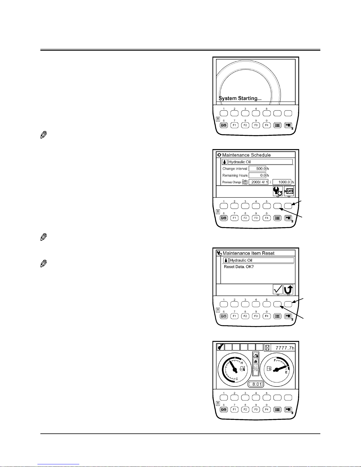
OPERATOR'S STATION
1-39
Screen Display when Maintenance Information Display
is ON
•
When only one item displays
1. If turning the key switch to the ON position, the starting
screen displays. Then, the scheduled maintenance screen
for the item whose change interval has expired displays
for three to ten seconds. Finally the basic screen displays.
(In the right example, Hydraulic Oil applies.)
NOTE: For a machine which the basic screen is displayed ac-
cording to a password on , the scheduled maintenance
screen for the item whose change interval has expired
displays for three to ten seconds, after the password is
input successfully and the determination key is pushed.
And then the basic screen displays.
2. If data is reset, push the reset key while the scheduled
maintenance screen is displayed.
The message “Reset Data. OK?” displays. Then, push the
determination key.
The value of remaining hours is reset to that of change
Interval. Previous change date/hour is updated with current date and time.
NOTE: When pushing the back key while the maintenance
information display screen is displayed, return to the
basic screen.
NOTE: When pushing the back key while reset screen is dis-
played, return to the maintenance information display
screen.
Reset Key
Back Key
Determination
Key
Back Key
T1V1-05-01-123
Basic Screen
T1V1-05-01-115
Starting Screen
Maintenance Information Display Screen
T1V5-05-01-170
T1V5-05-01-171
Reset Screen
Page 89

OPERATOR'S STATION
1-40
•
When more than two items apply
1. If turning the key switch to the ON position, the starting
screen displays. Then, the scheduled maintenance screen
for the items whose change interval has expired displays
for three to ten seconds. Finally the basic screen displays.
NOTE: For a machine which the basic screen is displayed ac-
cording to a password on, the scheduled maintenance
screen for the items whose change interval has expired
displays for three to ten seconds, after the password is
input successfully and the determination key is pushed.
And then the basic screen displays.
2. If data is reset, while the scheduled maintenance screen
is displayed, select desired item by using keys 1 and 2
. Push the determination key. Then, the maintenance
information display screen for the selected item displays.
(In the right example, Hydraulic Oil is selected.)
NOTE: When pushing the back key while the scheduled main-
tenance screen is displayed, the basic screen displays.
3. Push the reset key while the maintenance information
display screen is displayed.
The message “Reset Data. OK?” displays. Then, push the
determination key.
The value of remaining hours is reset to that of change
interval. Previous change date/hour is updated with current date and time.
NOTE: When pushing the back key while the maintenance
information display screen is displayed, return to the
scheduled maintenance screen.
NOTE: When pushing the back key while the reset screen is dis-
played, return to the maintenance information display
screen.
Dete rmin ation
Key
Back Key
Key 1
Key 2
T1V1-05-01-115
Starting Screen
Reset Key
Back Key
Back Key
Maintenance Information Display Screen
T1V5-05-01-170
T1V5-05-01-171
Reset Screen
T1V5-05-01-169
Scheduled Maintenance Screen
Page 90

OPERATOR'S STATION
1-41
Mailing Screen
Key F3
Back Key
T1V1-05-01-123
Mail
(Optional)
IMPORTANT: This function is available only to a machine
equipped with a satellite terminal.
When using the mail function, consult your
nearest Hitachi dealer.
1. When the basic screen displays, push mail selection key
F3 and display mail screen.
2. If pushing a relevant request key, mail information is sent
to ICF.
1 - General Request
2 - Fuel Replenishment Request
3 - Service Maintenance Request
4 - Forwarding Request
3. While mail information is sent to ICF, the message “Mail is
being delivered.” is displayed on the screen.
4. When ICF completes receives mail information, the mes
sage “Mail delivery successful.” is displayed on the screen.
When pushing the back key, return to the mail screen.
5. Then, a mail is sent from the satellite terminal to the cen
-
tral server via the satellite.
NOTE: Depending on machine’s operating environment or
position of the satellite on its orbit, the mail may not be
sent.
T1V5-05-01-037
T1V5-05-01-038
T1V5-05-01-039
2 31
4
Basic Screen
Page 91

OPERATOR'S STATION
1-42
NOTE: When satellite terminal could not receive the mail,
the message “Mail delivery failed.” is displayed on the
screen.
T1V5-05-01-040
Page 92

OPERATOR'S STATION
1-43
LANGUAGE SETTINGS
1. When the basic screen displayed, push the menu key and
display main menu.
2. Select language from main menu by using keys 1
and
2 . Push the determination key. Then, the language
settings screen displays.
3. Select a desired language by using keys 1
and 2 .
Push the determination key.
NOTE: Languages to be displayed on the screen of monitor
unit have been selected from twelve languages, namely
display languages 1 or 2, at the time of shipping from
the factory.
(Refer to the next section)
NOTE: When pushing the back key, return to the previous
screen.
4. Push key 6 , and the basic screen displays.
Key 6
T1V1-05-01-123
Basic Screen
T1V5-05-01-114
T1V1-05-01-137
Back KeyDetermination KeyKey 2Key 1
Back KeyDetermination KeyKey 2
Key 1
Menu Key
Page 93

OPERATOR'S STATION
1-44
Lists of Display Language
Display Languages 1
Language Screen Display
Japanese
T1V10501141
English
T1V10501142
Chinese (Simplified)
T1V10501143
Chinese (Traditional)
T1V10501144
Korean
T1V10501145
Indonesian
T1V10501146
Thai
T1V10501147
Vietnamese
T1V10501148
Myanmarese
T1V10501149
Arabic
T1V10501150
Persian
T1V10501151
Turkish
T1V10501152
Display Languages 2
Language Screen Display
English
T1V10501142
Spanish
T1V10501153
Italian
T1V10501154
French
T1V10501155
German
T1V10501156
Dutch
T1V10501157
Russian
T1V10501158
Portuguese
T1V10501159
Finnish
T1V10501160
Swedish
T1V10501161
Norwegian
T1V10501162
Danish
T1V10501163
Page 94

OPERATOR'S STATION
1-45
SWITCH PANEL
1- Engine Control Dial
2- Auto-Idle Switch
3- Power Mode Switch
4- Travel Mode Switch
5- Work Light Switch
6- Wiper/Washer Switch
Std. Model
1
2
3
4
5
6
M1U1-01-015
Page 95

OPERATOR'S STATION
1-46
ENGINE CONTROL DIAL
Use engine control dial (1) to adjust engine speed.
Turn it clockwise to increase engine speed or counterclockwise
to decrease engine speed.
•
The fully clockwise position : Fast idle
•
The fully counterclockwise position : Slow idle
AUTO-IDLE SWITCH
Auto-idle switch (2) sets the engine speed control mode to
Auto-Idle.
•
Auto-Idle Mode
When auto-idle switch (2) is turned to the A/I ON position,
the engine speed is reduced to slow idle speed 4 seconds
after releasing all control levers (neutral), reducing the fuel
consumption. When the auto-idle mode is selected, autoidle indicator (3) on the monitor panel lights.
Fast Idle
Slow Idle
A/I
OFF
A/I
ON
3
1
2
M1U1-01-033
M1U1-01-017
M1U1-01-004
Page 96

OPERATOR'S STATION
1-47
POWER MODE SWITCH
Three engine speed modes, E, P, and H/P modes, are selected
by operating the power mode switch.
•
E (Economy) Mode
Although production is slightly reduced more than in the P
mode, the fuel consumption and noise levels are reduced,
allowing the machine to operate efficiently.
•
P (Power) Mode
Use the P mode when general digging work is needed.
•
H/P (High Power) Mode
Use the H/P mode when extra horsepower is needed, i.e.
when rolling in the arm in excavation work, etc.
TRAVEL MODE SWITCH
Two travel modes, FAST and SLOW, are selected by turning the
travel mode switch to either position.
Mark (Fast Speed Mode)
Mark (Slow Speed Mode)
M178-01-013
M178-01-096
Page 97

OPERATOR'S STATION
1-48
WORK LIGHT SWITCH
Work light switch has the following positions:
• 1 Position
Work light (1) on the base machine will light. Also, the
instrument panel illumination will light.
• 2 Position
Work light (2) will light in addition.
• OFF Position
Work lights (1) and (2) and the instrument panel illumination will turn off.
M178-01-015
M157-01-146
2
1
Page 98

OPERATOR'S STATION
1-49
WIPER/WASHER SWITCH
The wiper and the window washer are operated using the
wiper/washer switch.
•
Wiper
Turn the wiper/washer switch to the specified position to
operate the wiper.
OFF Position: The wiper stops and is retracted.
INT Position: The wiper operates intermittently at the
interval selected by the switch position as
described below.
INT (Slow): The wiper operates at 8-second interval.
INT (Mid): The wiper operates at 6-second interval.
INT (Fast): The wiper operates at 3-second interval.
ON Position: The wiper operates continuously.
NOTE: • When the front window (upper) is opened, the wiper
and washer will not operate. Even if the front window
(upper) is closed, the wiper and washer will not operate until the lock pin on the right side is placed in the
lock position. If the front window is opened while
during operating the wiper, the wiper will be retracted
and the washer function is deactivated.
• In case either the wiper or washer is operated with
the front window (upper) opened, or if front window
(upper) is opened while operating either the wiper or
washer, the front window opening alarm buzzer will
sound intermittently at one-second intervals. Close the
front window (upper).
•
Washer (Std. Model)
Press and hold the wiper/washer switch to squirt washer
fluid onto the front window. When the wiper/washer switch
is pressed for more than 2 seconds, the wiper operates until
the switch is released. When the wiper/washer switch is
released, the wiper automatically retracts. While operating
the wiper in the INT mode, when the wiper/washer switch is
pressed, the wiper operation mode is changed to the continuous operation mode.
IMPORTANT: Washer motor may be damaged if wiper/
washer switch is held for more than 20 seconds, or continually operated with no fluid
in the washer tank.
M178-01-016
Fast
Mid
Slow
Wiper
M1U1-01-018
Page 99

OPERATOR'S STATION
1-50
•
Washer (Overhead Window)
As long as wiper washer switch (1) is held down, washer
fluid will be squirted from the nozzles on the front window
and overhead window. Continue holding wiper washer
switch (1) for more than 2 seconds to automatically operate
the front window wiper. Release wiper washer switch (1)
to stop fluid from being squirted from the nozzles and to
automatically stop and retract the wipers. While the wiper is
operating in the INT position, when wiper washer switch (1)
is pushed, the wiper will change to operate continuously.
IMPORTANT: The washer motor in the washer fluid tank
may be damaged if washer fluid is kept
squirted for more than 20 seconds or the
motor is continuously operated with the
washer fluid tank empty. Monitor the washer fluid squirting time and the fluid level in
the washer reservoir.
Wiper Switch (2) (Overhead Window: Optional)
Wiper switch (2) has two positions as follows:
ON Position ...........Overhead window wiper (3) operates.
OFF Position ..........Overhead window wiper (3) stops.
M1U1-01-007
M1U1-01-008
3
1
2
M157-01-081
Page 100

OPERATOR'S STATION
1-51
SWITCH PANEL (Optional)
NOTE: • The optional switch locations differ depending on
the kinds of optional devices are equipped. Before using the switches on the switch panel, make sure what
kind of optional devices are equipped. All available
optional devices are shown below.
• Raise the armrest when operating the optional
switch.
• Travel Alarm Deactivation
• Swing Alarm
• Rear Light
• Overload Alarm Device Switch
• Seat Heat Switch
• Rotating Lamp
• Electric Type Control Lever
Travel Alarm Deactivation Switch (Optional)
The travel alarm buzzer sounds during travel operation.
When push travel alarm deactivation switch (1) to the off
position ( ), the travel alarm buzzer function is deactivated.
Swing Alarm Switch (Optional)
The swing alarm system sounds the buzzer and turns the
beacon light ON during swing operation. When push swing
alarm switch (2) to the off position ( ), the swing alarm
buzzer function is deactivated.
Rear Light Switch (Optional)
When rear light switch (3) is turned ON. The rear light at the
rear of the cab roof comes ON.
M1U1-01-035
1
M1U1-01-036
2
M1U1-01-009
3
T1V1-05-02-004
Optional Switch
Armrest
 Loading...