

Page 1
YK
No.024E
SERVICE MANUAL
The LCD panel made from AUO is used for this product.
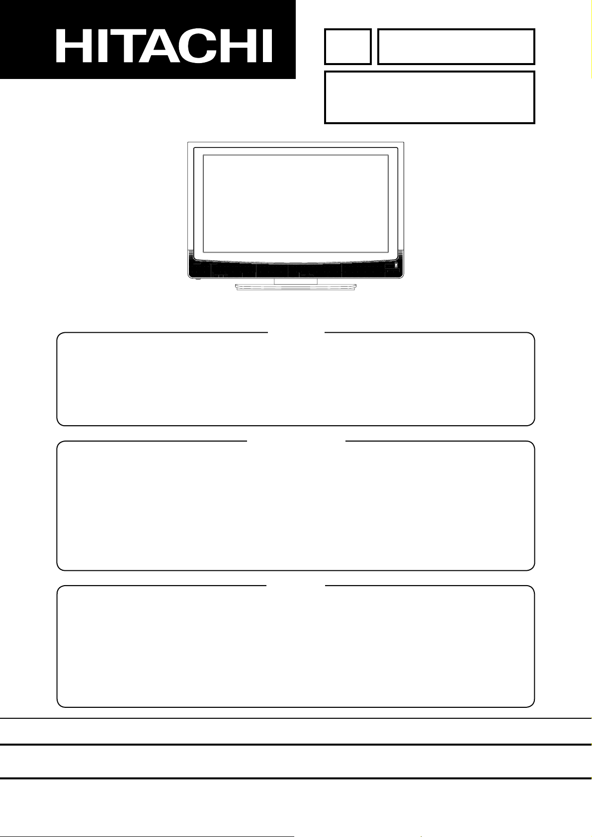
32LD380TA
Caution
Be sure to read this manual before servicing. To ensure safety from fi re, electric shock, injury, harmful
radiation and materials, various measures are provided in this Plasma Monitor.
Be sure to read cautionary items described in the manual before servicing.
These servicing instructions are for use by qualifi ed service personnel only. To reduce the risk of electric
shock, do not perform any servicing other than that described in the operating instructions unless you
are qualifi ed to do so.
Service Warning
1. Since the Panel Module and the front Filter are made of glass, handling the broken Module and Filter
carefully and with caution in order not to receive injury.
2. Replacement work should be started after the Panel Module and the AC/DC Power supply have
become suffi ciently cool.
3. Special care should be taken when working near the display area in order not to damage its surface.
4. The Panel Module should not be touched with bare hands in order to protect its surface from
blemishes and damage.
5. It is recommended that you use clean soft gloves during the replacement work in order to protect not
only the display area of the Panel Module but also yourself.
Contents
LOCATION OF CONTROL ----------------------------3
REMOTE CONTROL ----------------------------------- 4
GENERAL SPECIFICATIONS -----------------------5
DISASSEMBLY INSTRUCTIONS ----------------- 11
SERVICE MODE LIST ------------------------------- 13
WHEN REPLACING EEPROM -------------------- 13
ELECTRICAL ADJUSTMENTS -------------------- 14
BLOCK DIAGRAM ------------------------------------ 17
PRINTED CIRCUIT BOARDS ---------------------- 23
INTERCONNECTION DIAGRAM ----------------- 29
MECHANICAL EXPLODED VIEW ---------------- 30
MECHANICAL REPLACEMENT PARTS LIST
ELECTRICAL REPLACEMENT PARTS LIST
------- 33
-------- 35
SPECIFICATIONS AND PARTS ARE SUBJECT TO CHANGE FOR IMPROVEMENT.
LCD Display
January 2006 Digital Media Division
Page 2

CAUTION FOR SAFETY
2
Please read this page before repair the monitor.
This page explains to following items for keep the safety of set and prevent to accident
during repair work.
We explain by symbol at happen the damage or injury when took wrong repair.
Warning
Caution
We made the symbol as below, which are kind of following items.
This symbol means "CAUTION"
This symbol means "POSSIBLE to
ELECTRIC SHOCK"
This symbol means "possible to die or heavy damage"
This symbol means "possible to damage or something will break"
This symbol means "MUST"
This symbol means "DO NOT"
WARNING
Should be follows to instructions.
We indicates to cabinet, chassis and
parts by label, which are special atten-
tion part.
Please follow to note and [Safety
Instructions] of User’s Manual.
Prevent the electric shock.
Please take care during working
because monitor has high voltage part
and power supply part.
Possible to die if you touch to these
place by miss take.
Please disconnect power plug during
overhaul, reassemble or change parts.
You will die or take damage by electric
shock if you touch to live part.
Use recommended components.
Please use to same characteristic com-
ponent, which is same as previous for
your safety and keep reliability espe-
cially marked by
cuit diagram.
It is reason of electric shock or fire if
you use non-recommended compo-
nent.
in parts list and cir-
Should be kept same style of wiring or component.
Monitor uses tubes or tapes, which
made by insulator, and some components are keep distance from surface of
PWB for safety.
Internal leads kept from hot part or high
voltage part by clamper or styling, so
please return to original condition for
prevent to electric shock or fire.
Should be done safety check after finished.
Every part (removed screws, component and wiring) should be returned to
previous condition.
Check around repair position for make
damage by miss take and measure the
insulated impedance by meg-ohm
meter.
Confirm the value of impedance, that
value is more than 4M ohm.
It is reason for electric shock or fire if
that value is less than 4M ohm.
Nobody can check and repair to the code
and combination circuit of HDCP.
Never remove the shield case, which is
assembled to the code and combination
circuit of HDCP.
Page 3
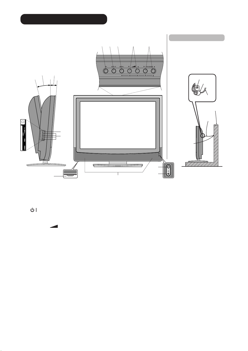
Location of controls
3
You can adjust the angle of
the TV-screen for 2˚ forward
or for 6˚ backward from
vertical angle.
Left Side
Approx. 6˚
Approx. 2˚
Front Side
6
AV3 IN
7
8
Top
2
1
34
5
Securing to a wall or pillar
Using a commercially
available cord, chain, and
clamp, secure the set to a wall
or pillar.
screw
hook
cord or
chain
Wall or Pillar
cord or
chain
clamp
10
11
9
Anti-Tumble Measure
Description of Indicators and Controls
1. (SUB-POWER) button: To turn the unit standby mode on and off.
2. INPUT-button: Select input mode for TV/AV/COMPONENT/HDMI/PC.
3. MENU-button: To display the menu-screen.
4. VOLUME
5. PROGRAM ▲/▼ buttons: Press ▲ to change to a higher numbered channel set into memory. Press
▼ to change to a lower numbered channel set into memory. In Menu : Setting. In Standby : Turning
on the unit.
6. HEADPHONES jack: Plug headphones with a mini plug (3.5 mm) into this jack.
7. AV3-Input: Input for analogue A/V-Signal (Composite). If your equipment has an S-video connector,
use an S-video cable instead of a standard yellow video cable (You still must connect the standard
red and white audio cables for full system connection, but do not connect a standard yellow video
cable at the same time or the picture performance will be unacceptable.)
8. Main Power Switch: To turn the unit on or off completely.
9. Loudspeakers
10. Remote sensor
11. STANDBY/ON mode indicator: It lights up in red at STANDBY, and in green at POWER ON.
▲/▼ buttons : To adjust the volume. In Menu : Setting.
Page 4
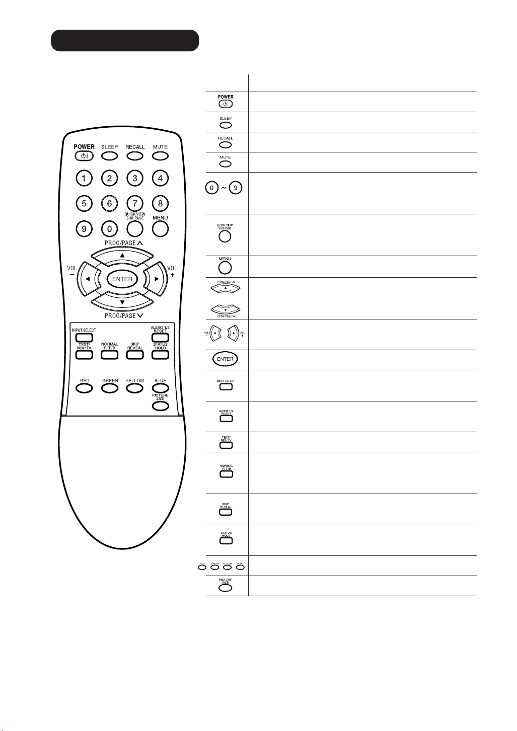
Remote Control
4
Function
Turn the unit on or off
Sleep-Timer
Display program position number
Turn the sound on/off
Select channel
Select Teletext page
Enter Password
Switches between the present channel and the
last selected channel
Sub Page selection
Call Menu
Select TV-channel or
In Menu: Setting
In Standby: Turning on the unit
Volume
In Menu: Setting
Memorize
Select input source
Two Channel-Sound AUDIO 1/2 selector
Teletext page 100
Teletext ON/ Mix/ OFF
Reset Sound/Picture
Teletext enlargement
Program position-skipping
Answer a Quiz
Teletext-Timer display
Hold the text page
Fastext/TOPtext buttons
Teletext
page step by step
Select picture format
Page 5
GENERAL SPECIFICATIONS
5
G-1 TV LCD LCD Size / Visual Size 31.5 inch / 800.4mmV
System LCD Type Color TFT LCD
Color System PAL/SECAM/NTSC
Speaker 2 Speaker
Sound Output MAX 10W + 10W
NTSC3.58+4.43 /PAL60Hz Yes
G-2 Tuning Broadcasting System
System Tuner and System 1Tuner
Receive CH Destination UK, CCIR Hyper, USA
Intermediate
Frequency Picture(FP)
Auto Tuning Method
Preset CH 110
Stereo/Dual TV Sound NICAM/A2 Dual
Tuner Sound Muting Yes
G-3 Power Power Source AC 100-240V AC 50/60Hz
Power Consumption at AC 150 W at AC 100-240 V 50/60 Hz
Protector Power Fuse Yes
G-4 Regulation Safety IEC60065,GOST, CB, AS/NZS, PSB
G-5 Temperature Operation +5oC ~ +40oC
G-6 Operating Humidity Less than 80% RH
Number of Pixels(H x V) 1366(H) x 768(V)
View Range Left/Right 85/85 degree
Position Front
Size 2.2 x 5.0 inch
Impedance 4 ohm
10%(Typical) ---
CH Coverage
Sound(FS)
FP-FS
DC ---
Stand by (at AC) 1 W at AC 100-240 V 50/60 Hz
Per Year -- kWh/Year
Energy Star Yes
Safety Circuit Yes
IC Protector(Micro Fuse) Yes
Radiation CISPR, GOST, AS/NZS
X-Radiation ---
Storage -20oC ~ +60oC
Up/Down 85/85 degree
U.K., CCIR, US System
B/G, D/K, I/I, M
1~S6, S7~S36, S37~E69
PAL/SECAM(U&VH)/NTSC
38.9/38.9/38.9/38.9MHz
33.4/32.9/32.4/34.4MHz
5.5/6.0/6.5/4.5MHz
ALL Band (Not C.C.I.R. CH Plan)
at DC --
Page 6
GENERAL SPECIFICATIONS
6
G-7 On Screen Menu (TV) Yes
Display Menu Type Icon
Menu (PC) Yes
Picture Yes
Audio Yes
Setup Yes
Option
Picture Yes
Audio Yes
Brightness Yes
Contrast Yes
Color Yes
Tint (NTSC Only) Yes
Sharpness Yes
DNR On/Off Yes
Color Temperature Yes
Blue Back No
Film Mode Yes
NICAM Auto/Off Yes
Bass Yes
Treble Yes
Balance Yes
Perfect Volume Yes
Surround On/Off No
Speakers On/Off Yes
HDMI Yes
BBE No
WOW SRS 3D Yes
WOW Focus Yes
WOW Trubass Yes
Auto Tuning Yes
Manual Tuning Yes
Sort(CH Allocation) Yes
Backlight Yes
Text Language Yes
Language Yes
Position (Vertical Position) Yes
Auto 4:3 Default No
AV2 Output No
AV2 Input No
Color System(AV Color) Yes
Inversion No
Screen Wipe(Full White) No
Screen Saver No
Static Image No
Yes
On Timer Yes
Off Timer Yes
Panel Lock Yes
Brightness Yes
Contrast Yes
HOR Position Yes
VER Position Yes
Clock Phase Yes
Horizontal Clock Yes
AUTO ADJUST No
Amplitude Red Yes
Amplitude Green Yes
Amplitude Blue Yes
WXGA Mode Yes
WVGA Mode Yes
NICAM Auto/Off No
Bass Yes
Treble Yes
Balance Yes
Perfect Volume Yes
Surround On/Off No
Speakers On/Off Yes
HDMI Yes
BBE No
WOW SRS 3D Yes
WOW Focus Yes
WOW Trubass Yes
Page 7
GENERAL SPECIFICATIONS
7
Control Level Yes
Nicam ST Yes
Tone 1/2 Yes
Pin Code No
Freeze No
CH/AV/PC Yes
Hotel Lock No
Wide Mode Yes
Sleep Timer Yes
Sound Mute Yes
Input Select Yes
NOT AVAILABLE Yes
G-8 OSD Language English / Chinese(Simplified) /
G-9 Clock and Sleep Timer Max Time 120 Min
Timer Step 10 Min
On/Off Timer Program(On Timer / Off Timer) 1 Program
Wake Up Timer No
Timer Back-up (at Power Off Mode) more than -- Min Sec
Volume Yes
Brightness Yes
Contrast Yes
Color Yes
Tint (NTSC Only) Yes
Sharpness Yes
Tuning Yes
Bass Yes
Treble Yes
Balance Yes
HOR Position Yes
VER Position Yes
Clock Phase Yes
Horizontal Clock Yes
Amplitude Red Yes
Amplitude Green Yes
Amplitude Blue Yes
Backlight Yes
Chinese(Traditional) / Russia
Page 8
GENERAL SPECIFICATIONS
8
G-10 Remote Unit RC-MA
Control Glow in Dark Remocon No
Remocon Format HITACHI
Format HITACHI
Custom Code 50-AF h
Power Source Voltage(D.C) 3V
Total Keys
Keys Power ( Stand By ) Yes
T'TEXT Keys TEXT / MIX / TV Yes
UM size x pcs UM-4 x 2 pcs
32
1 Yes
2 Yes
3 Yes
4 Yes
5 Yes
6 Yes
7 Yes
8 Yes
9 Yes
0 Yes
Volume Up / Right Yes
Volume Down / Left Yes
Sleep Yes
Recall (CH Call) Yes
Menu Yes
Enter Yes
Mute Yes
Picture Size Yes
Fine Tuning + No
Fine Tuning - No
Input Select Yes
Multi Picture No
Picture Position No
Picture Main/Sub No
CH Up / Page Up / Up Yes
CH Down / Page Down / Down Yes
Red Yes
Green Yes
Yellow Yes
Blue Yes
F/T/B(Expand) / Normal Yes
Reveal / Skip Yes
Reset / Audio 1/2 Yes
Hold / Status Yes
Sub Page / Quick View Yes
Page 9
GENERAL SPECIFICATIONS
9
G-11 Features Auto Shut Off Yes
G-12 Accessories Owner's Manual Language English / Chinese(Simplified) /
BBE No
SRS WOW(SRS 3D/Focus/Tru Bass) Yes
Variable Audio Out Yes
Auto Search Yes
CH Sort(CH Allocation) Yes
Channel Lock No
Just Clock Function No
Game Position No
CH Label No
T'Text Yes
Wide Mode Yes
Picture Scroll Yes
DNR Yes
Comb Filter Yes
Surround No
Backlight Yes
Perfect Volume(Stable Sound) Yes
PFC(Power Factor circuit) Yes
Auto Set Up No
Power On Memory Yes
Hotel Lock No
PC Monitor Input Yes
Freeze frame No
Remote Control Unit Yes
Rod Antenna
Loop Antenna (W/ Antenna Change Plug)
U/V Mixer
DC Car Cord (Center+)
Guarantee Card
Warning Sheet
Circuit Diagram
Antenna Change Plug
Service Facility List
Important Safeguard
Dew/AHC Caution Sheet
Quick Set-up Sheet
Battery Yes
AC Adapter
AC Cord (for AC Adapter)
AC Cord Yes
AV Cord (2Pin-1Pin)
HDMI-DVI Cable
Registration Card
300 ohm to 75 ohm Antenna Adapter
Text type Fastext / Toptext
Text Language English , French, Swedish, Hungarian
w/Guarantee Card
Poles Terminal -
Terminal -
UM size x pcs UM-4 x 2 pcs
OEM Brand Yes(Maxell)
Finnish, Turkish, German, Dutch
Portuguese, Spanish, Italian, Greek
Polish, Russian, Bulgarian,
Serbian, Croatian, Slovene,
Czech, Slovakian, Rumanian.
3D
5 Lines
Chinese(Traditional) / Russia
No
No
No
No
No
No
No
No
No
No
No
No
No
No
No
No
No
No
No
Page 10
GENERAL SPECIFICATIONS
10
G-13 Interface Switch Front Sub Power (Tact) Yes
Indicator Power / Stand-by Yes(GREEN / RED)
Terminals Rear Video Input 1 RCA x 1
Side Video Input 3 RCA x 1
G-14 Set Size Approx. W x D x H (mm) 822 x 332.5 x 604
G-15 Weight Net Approx. 19.0kg (41.9 lbs)
G-16 Carton Master Carton
Gift Box Material Double/Brown
Drop Test
Container Stuffing 201
G-17 Material Cabinet Cabinet Front PS 94V0 Non-Halogen
PCB Non-Halogen
G-18 Environment Environmental standard requirement Green procurement of HITACHI
Pb-free Phase3(Phase3A)
WEEE
System Select No
Main Power SW Yes
Channel Up/Menu Up Yes
Channel Down/Menu Down Yes
Volume Up/Menu > Yes
Volume Down/Menu < Yes
Input Select Yes
Menu Yes
On Timer No
Audio Input
S- Input
Video Input 2 RCA x 1
Audio Input
S- Input
Video Output RCA x 1
Audio Output RCA x 2(Variable L, R)
Component In 1
Audio Input (Component In use)
Component In 2
Audio Input (Component In use)
Other Terminal No
Euro Scart (21Pin) No
HDMI Input(w/ Analog Audio L/R)
Sub Woofer Out Yes
PC Monitor Input (D-Sub)
Audio Input
Diversity No
Ext Speaker No
DC Jack 12V(Center +) No
VHF/UHF Antenna Input
AC Inlet
Audio Input RCA x2(L/MONO,R)
S- Input
Other Terminal Headphone
w/o Stand,Handle Approx. W x D x H (mm)
Net w/o Stand,Handle Approx. 16.5kg (36.4 lbs)
Gross Approx. 23.0kg (50.7 lbs)
Content --- Sets
Material --- / --Dimensions W x D x H(mm) --Description of Origin ---
Dimensions W x D x H(mm) 917 x 441 x 720
Design As per Buyer's
Description of Origin
Height (cm) 46
Cabinet Rear PS 94V0 Non-Halogen
Eyelet Yes
RCA x 2(L/MONO, R)
Yes
RCA x 2(L/MONO, R)
Yes
RCA x 3
RCA x 2(L/MONO, R)
RCA x 3
RCA x 2(L/MONO, R)
Yes
Yes
φMini Pin Jack(3.5), STEREO
DIN Type
Yes
Yes
822 x 115 x 556.5
No
No
Natural Dropping At 1 Corner / 3 Edges /
6 Surfaces
Sets/40' container
No
No
Page 11
DISASSEMBLY INSTRUCTIONS
11
1.
REMOVAL AND INSTALLATION OF
FLAT PACKAGE IC
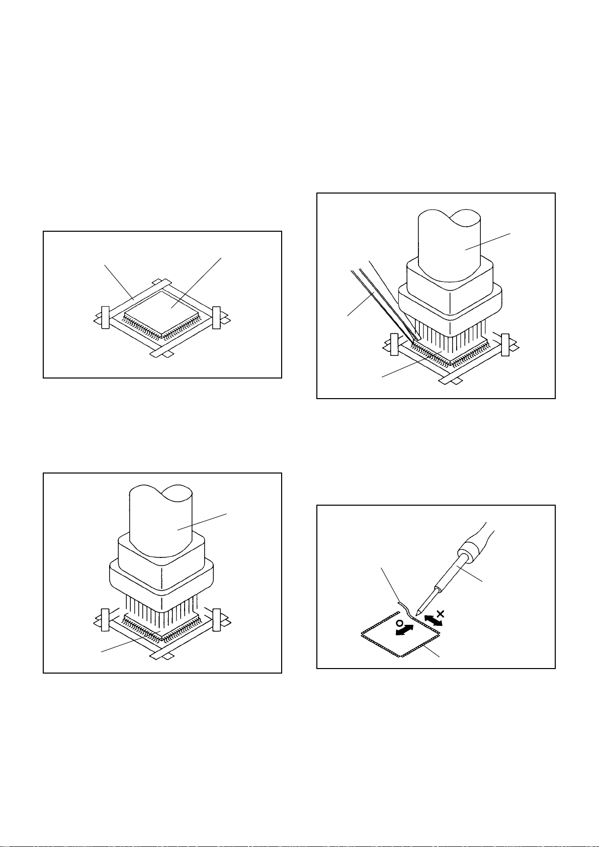
REMOVAL
Put Masking Tape (cotton tape) around the Flat Package
1.
IC to protect other parts from any damage.
(Refer to Fig. 1-1.)
NOTE
Masking is carried out on all the parts located within
10 mm distance from IC leads.
When IC starts moving back and forth easily after
3.
desoldering completely, pickup the corner of the IC using
tweezers and remove the IC by moving with the IC
desoldering machine. (Refer to Fig. 1-3.)
NOTE
Some ICs on the PCB are affixed with glue, so be
careful not to break or damage the foil of each IC
leads or solder lands under the IC when removing it.
Blower type IC
desoldering
machine
Masking Tape
(Cotton Tape)
Heat the IC leads using a blower type IC desoldering
2.
IC
machine. (Refer to Fig. 1-2.)
NOTE
Do not rotate or move the IC back and forth , until IC
can move back and forth easily after desoldering the
leads completely.
Blower type IC
desoldering machine
Fig. 1-1
Tweezers
IC
Peel off the Masking Tape.4.
Absorb the solder left on the pattern using the Braided
5.
Shield Wire. (Refer to Fig. 1-4.)
NOTE
Do not move the Braided Shield Wire in the vertical
direction towards the IC pattern.
Fig. 1-3
Braided Shield Wire
Soldering Iron
IC
Fig. 1-2
IC pattern
Fig. 1-4
Page 12

DISASSEMBLY INSTRUCTIONS
12
INSTALLATION
Take care of the polarity of new IC and then install the
1.
new IC fitting on the printed circuit pattern. Then solder
each lead on the diagonal positions of IC temporarily.
(Refer to Fig. 1-5.)
Soldering Iron
Solder temporarily
Supply the solder from the upper position of IC leads
2.
Solder temporarily
sliding to the lower position of the IC leads.
(Refer to Fig. 1-6.)
Fig. 1-5
When bridge-soldering between terminals and/or the
4.
soldering amount are not enough, resolder using a Thintip Soldering Iron. (Refer to Fig. 1-8.)
Thin-tip Soldering Iron
IC
Fig. 1-8
Finally, confirm the soldering status on four sides of the
5.
IC using a magnifying glass.
Confirm that no abnormality is found on the soldering
position and installation position of the parts around the
IC. If some abnormality is found, correct by resoldering.
NOTE
When the IC leads are bent during soldering and/or
repairing, do not repair the bending of leads. If the
bending of leads are repaired, the pattern may be
damaged. So, always be sure to replace the IC in this
case.
Soldering IronSolder
IC
Absorb the solder left on the lead using the Braided
3.
Supply soldering
from upper position
to lower position
Shield Wire. (Refer to Fig. 1-7.)
NOTE
Do not absorb the solder to excess.
Soldering Iron
IC
Braided Shield Wire
Fig. 1-6
Fig. 1-7
Page 13

SERVICE MODE LIST
13
This unit is provided with the following SERVICE MODES so you can repair, examine and adjust easily.
To enter to the SERVICE MODE function, press and hold both buttons simultaneously on the main unit and on the remote
control for more than the standard time in the appropriate condition. (See below chart.)
Set
Condition
TV mode
TV mode
TV mode
TV mode
ALL mode
Set Key Operations
VOL. DOWN
(Minimum)
Remocon
Key
0
Standard
Time
2 sec.
Reset the user setting items (PICTURE, VOLUME and
LANGUAGE) to the initial state for delivery.
Password is released.
Initialization of factory TV data.
VOL. DOWN
(Minimum)
1 2 sec.
NOTE:
If you set factory initialization, the memories are reset
such as the channel setting, and the POWER ON total
hours.
VOL. DOWN
(Minimum)
2
2 sec.
Check of the SUM DATA and MICON VERSION on the screen.
Refer to the "
CONFIRMATION OF CHECK SUM, POWER ON
TOTAL HOURS AND MICON VERSION
POWER ON total hours are displayed on the screen.
VOL. DOWN
(Minimum)
6 2 sec.
Refer to the "
TOTAL HOURS AND MICON VERSION
CONFIRMATION OF CHECK SUM, POWER ON
Can be checked of the INITIAL DATA of MEMORY IC.
Refer to the "WHEN REPLACING EEPROM (MEMORY) IC".
VOL. DOWN
(Minimum)
9 2 sec.
Display of the Adjustment MENU on the screen.
Refer to the "ELECTRICAL ADJUSTMENT" (On-Screen Display
Adjustment).
".
"
WHEN REPLACING EEPROM (MEMORY) IC
CONFIRMATION OF CHECK SUM, POWER ON TOTAL HOURS AND MICON VERSION
Initial total of MEMORY IC, POWER ON total hours and MICON VERSION can be checked on the screen. Total hours are
displayed in 16 system of notation.
NOTE:
1.
2.
3.
4.
If you set a factory initialization, the total hours is reset to "0".
Please refer to "CONFIRMATION OF INITIAL DATA" when SUM DATA is not corresponding.
Turn on the POWER, and set to the TV mode.
Set the VOLUME to minimum.
Press both VOL. DOWN button on the set and Channel
button (8) on the remote control for more than 2 seconds.
After the confirmation of each check sum, turn off the
power.
INIT
ROM
ADC
DVP
LCD ON
OEC7145A_030
: 4F7D
: 0000
: C154
: A615
: 0000
FIG. 1
Initialsetting data check sum.
Rom correction data check sum.
AD CONVERTER data check sum.
SCALER data check sum.
POWER ON total hours.
= (16 x 16 x 16 x thousands digit value)
+ (16 x 16 x hundreds digit value)
+ (16 x tens digit value)
+ (ones digit value)
MICON Version
Page 14

ELECTRICAL ADJUSTMENTS
14
1. ADJUSTMENT PROCEDURE
Read and perform these adjustments when repairing the
circuits or replacing electrical parts or PCB assemblies.
CAUTION
•
Use an isolation transformer when performing any
service on this chassis.
•
When removing a PCB or related component, after
unfastening or changing a wire, be sure to put the wire
back in its original position.
•
When you exchange IC and Transistor with a heat sink,
apply silicon grease (YG6260M) on the contact section of
the heat sink. Before applying new silicon grease,
remove all the old silicon grease. (Old grease may cause
damage to the IC and Transistor).
Prepare the following measurement tools for electrical
adjustments.
1. Pattern Generator
2. BASIC ADJUSTMENTS
On-Screen Display Adjustment
1.2.Set the VOLUME to minimum.
Press the VOL. DOWN button on the set and the
channel button (9) on the remote control for more than
2 seconds to display adjustment mode on the screen as
shown in Fig. 2-1.
TV
AUTO
01 H POSI OSD
3.
Use the Channel UP/DOWN button or Channel button
(0-9) on the remote control to select the options shown
in Fig. 2-2.
4.
Press the MENU button on the remote control to end
the adjustments.
5.
To display the adjustment screen for AV, HDMI and
COMPONENT mode, press the INPUT SELECT button
on the remote control to set to the AV, HDMI and
COMPONENT mode. Press the VOL.DOWN button on
the set and the channel (9) on the remote control for
more than 2 seconds.
90
Fig. 2-1
NO.
NO.
FUNCTION
01
H POSI OSD
02
V POSI OSD
03
R DRIVE (N)
04
R CUT OFF (N)
05
G DRIVE (N)
06
G CUT OFF (N)
07
B DRIVE (N)
08
B CUT OFF (N)
09
R DRIVE (C)
10
R CUT OFF (C)
11
G DRIVE (C)
12
G CUT OFF (C)
13
B DRIVE (C)
14
B CUT OFF (C)
15
R DRIVE (W)
16
R CUT OFF (W)
17
G DRIVE (W)
18
G CUT OFF (W)
19
B DRIVE (W)
20
B CUT OFF (W)
21
H POSI 50Hz
FUNCTION
22
H POSI 60Hz
23
V POSI 50Hz
24
V POSI 60Hz
25
BAK LIGHT CENT
26
BAK LIGHT MAX
27
BAK LIGHT MIN
28
BRIGHT CENT
29
BRIGHT MAX
30
BRIGHT MIN
31
TINT
35
CONTRAST CENTER
36
CONTRAST MAX
37
CONTRAST MIN
38
COLOR CENT
39
COLOR MAX
40
COLOR MIN
41
H POSI TEXT
42
V POSI TEXT
43
NT COLOR CENT
44
NT COLOR MAX
45
NT COLOR MIN
Fig. 2-2
2-1: CONTRAST
1.
Receive the monoscope pattern.(RF Input)
2.
Activate the adjustment mode display of Fig. 1-1 and
press the channel button (35) on the remote control to
select "CONTRAST CENTER".
3.
Check if the step No. CONTRAST CENTER is "147".
4.
Receive a broadcast and check if the picture is normal.
5.
Press the INPUT SELECT button on the remote control
to set to the AV mode.
6.
Activate the adjustment mode display of Fig. 1-1 and
press the channel button (35) on the remote control to
select "CONTRAST CENTER".
7.
Check if the step No. CONTRAST CENTER is "147".
8.
Receive a broadcast and check if the picture is normal.
9.
Receive a Color Bar Pattern.
10.
Press the INPUT SELECT button on the remote control
to set to the COMPONENT mode.
11.
Activate the adjustment mode display of Fig. 1-1 and
press the channel button (35) on the remote control to
select "CONTRAST CENTER".
12.
Check if the step No. CONTRAST CENTER is "147".
13.
Receive a broadcast and check if the picture is normal.
14.
Playback the DVD disc. (480i input)
15.
Press the INPUT SELECT button on the remote control
to set to the HDMI mode.
16.
Activate the adjustment mode display of Fig. 1-1 and
press the channel button (35) on the remote control to
select "CONTRAST CENTER".
17.
Check if the step No. CONTRAST CENTER is "147".
Receive a broadcast and check if the picture is normal.
Page 15

ELECTRICAL ADJUSTMENTS
15
2-2: Confirmation of Fixed Value (Step No.)
Please check if the fixed values of each the adjustment items are set correctly referring below. (TV/AV/COMPONENT/HD-MI)
COMPONENT HD-MI
TV AV
PAL SECAM NTSC PAL SECAM NTSC 480i 480p 720p 1080i 576i 576p 720p 1080i 480i 480p 720p 1080i 576i 576p 720p 1080i
NO. FUNCTION Step No. Step No. Step No. Step No. Step No. Step No. Step No. Step No. Step No. Step No. Step No. Step No. Step No. Step No. Step No. Step No. Step No. Step No. Step No. Step No. Step No. Step No.
1H POSI OSD 7777777777777777777777
2 V POSI OSD 85 85 85 85 85 85 85 85 85 85 85 85 85 85 85 85 85 85 85 85 85 85
3 R DRIVE (N) 127 127 127 127 127 127 127 127 127 127 127 127 127 127 127 127 127 127 127 127 127 127
4 R CUT OFF (N) 128 128 128 128 128 128 128 128 128 128 128 128 128 128 128 128 128 128 128 128 128 128
5 G DRIVE (N) 128 128 128 128 128 128 128 128 128 128 128 128 128 128 128 128 128 128 128 128 128 128
6 G CUT OFF (N) 128 128 128 128 128 128 128 128 128 128 128 128 128 128 128 128 128 128 128 128 128 128
7 B DRIVE (N) 121 121 121 121 121 121 121 121 121 121 121 121 121 121 121 121 121 121 121 121 121 121
8 B CUT OFF (N) 128 128 128 128 128 128 128 128 128 128 128 128 128 128 128 128 128 128 128 128 128 128
9 R DRIVE (C) 120 120 120 120 120 120 120 120 120 120 120 120 120 120 120 120 120 120 120 120 120 120
10 R CUT OFF (C) 121 121 121 121 121 121 121 121 121 121 121 121 121 121 121 121 121 121 121 121 121 121
11 G DRIVE (C) 120 120 120 120 120 120 120 120 120 120 120 120 120 120 120 120 120 120 120 120 120 120
12 G CUT OFF (C) 120 120 120 120 120 120 120 120 120 120 120 120 120 120 120 120 120 120 120 120 120 120
13 B DRIVE (C) 130 130 130 130 130 130 130 130 130 130 130 130 130 130 130 130 130 130 130 130 130 130
14 B CUT OFF (C) 120 120 120 120 120 120 120 120 120 120 120 120 120 120 120 120 120 120 120 120 120 120
15 R DRIVE (W) 133 133 133 133 133 133 133 133 133 133 133 133 133 133 133 133 133 133 133 133 133 133
16 R CUT OFF (W) 128 128 128 128 128 128 128 128 128 128 128 128 128 128 128 128 128 128 128 128 128 128
17 G DRIVE (W) 128 128 128 128 128 128 128 128 128 128 128 128 128 128 128 128 128 128 128 128 128 128
18 G CUT OFF (W) 128 128 128 128 128 128 128 128 128 128 128 128 128 128 128 128 128 128 128 128 128 128
19 B DRIVE (W) 118 118 118 118 118 118 118 118 118 118 118 118 118 118 118 118 118 118 118 118 118 118
20 B CUT OFF (W) 128 128 128 128 128 128 128 128 128 128 128 128 128 128 128 128 128 128 128 128 128 128
21 H POSI 50Hz 325 325 325 325 325 325 .. .. .. .. 322 158 336 290 .. .. .. .. 320 158 292 244
22 H POSI 60Hz 294 294 294 294 294 294 292 142 336 294 .. .. .. .. 279 152 296 250 .. .. .. ..
23 V POSI 50Hz 87 87 87 87 87 87 .. .. .. .. 89 88 54 49 .. .. .. .. 79 83 50 45
24 V POSI 60Hz 79 79 79 79 79 79 77 82 55 46 .. .. .. .. 79 75 47 42 .. .. .. ..
25 BAK LIGHT CENT 128 128 128 128 128 128 128 128 128 128 128 128 128 128 128 128 128 128 128 128 128 128
26 BAK LIGHT MAX 255 255 255 255 255 255 255 255 255 255 255 255 255 255 255 255 255 255 255 255 255 255
27 BAK LIGHT MIN 0 0 0 0000000000000000000
28 BRIGHT CENT 127 127 127 127 127 127 127 128 130 128 129 129 130 128 125 125 125 125 125 125 125 125
29 BRIGHT MAX 156 156 156 156 156 156 156 156 156 156 156 156 156 156 156 156 156 156 156 156 156 156
30BRIGHT MIN 96969696969696969696969696969696969696969696
31 TINT 116 116 116 116 116 116 119 123 129 129 119 119 129 129 129 129 123 123 129 129 123 123
35 CONTRAST CENTER 116 116 116 173 173 173 149 186 186 188 163 188 186 188 182 182 173 153 178 178 173 153
36 CONTRAST MAX 190 190 190 190 190 190 190 190 190 190 190 190 190 190 190 190 190 190 190 190 190 190
37 CONTRAST MIN 85 85 85 85 85 85 85 85 85 85 85 85 85 85 85 85 85 85 85 85 85 85
38 COLOR CENT 80 80 80 68 68 68 .. .. .. .. 76 76 76 76 71 71 78 78
39 COLOR MAX 127 127 127 127 127 127 127 127 127 127 127 127 127 127 127 127 127 127 127 127 127 127
40COLOR MIN 0000000000000000000000
41 H POSI TEXT 181 181 181 181 181 181 .. .. .. .. .. .. .. .. .. .. .. .. .. .. .. ..
42 V POSI TEXT 82 82 82 82 82 82 .. .. .. .. .. .. .. .. .. .. .. .. .. .. .. ..
43NT COLOR CENT 74747465656581787878 .. .. .. .. 78787878 .. .. .. ..
44 NT COLOR MAX 127 127 127 127 127 127 127 127 127 127 127 127 127 127 127 127 127 127 127 127 127 127
45NT COLOR MIN 0000000000000000000000
60Hz 50Hz 60Hz 50Hz
Page 16

ELECTRICAL ADJUSTMENTS
16
3. ELECTRICAL ADJUSTMENT PARTS LOCATION GUIDE (WIRING CONNECTION)
D
A
15
F
16
17
4
5 6
1
7
8
11
E
H
9
12
B
2
3
10
13
14
G
I
18
C
Item No. Wire
1
CD4205
2
CD301
3
CD303
4
CD3806
CD517
5
6
CD520
7
CD3804
8
CD4202
9
CD3807
CD4201
10
CORD,CONNECTOR
CU257501
CORD,CONNECTOR
CU125503
CORD,CONNECTOR
CU127502
CORD,CONNECTOR
CU145003
CORD,CONNECTOR
CU1C2002
CORD,CONNECTOR
CU122002
CORD,CONNECTOR
CU174001
CORD,CONNECTOR
CU255502
CORD,CONNECTOR
CU2B1501
CORD,CONNECTOR
CU287001
Part No.
06CU257501
06CU125503
06CU127502
06CU145003
06CU1C2002
06CU122002
06CU174001
06CU255502
06CU2B1501
06CU287001
HITACHI Part No.
TE03835
TE03703
TE03704
TE03831
TE03708
TE03834
TE03832
TE03833
Item
11
12
13
14
15
16
17
18
REF.NO.
CD4204
CD4203
CD3601
CD2201
CD518
CD519
CD516
CD509
DESCRIPTION PART NO.
CORD,JUMPER
2H0U0803
CORD,JUMPER
2H0U0802
CORD,CONNECTOR
CU1K6001
CORD,CONNECTOR
CU235501
CORD,CONNECTOR
CU1B2002
CORD,CONNECTOR
CU252001
CORD,CONNECTOR
CUU25102
CORD,CONNECTOR
CUU23501
122H0U0802
122H0T0801
06CU1K6001
06CU235501
06CU1B2002
06CU252001
06CUU25102
06CUU23501
HITACHI PART NO.
TE03415
TE03416
TE03707
Item
REF.NO.
DESCRIPTION PART NO. HITACHI PART NO.
J
Item Board PART NO. HITACHI PART NO.
REGULATOR PCB ASS'Y(PCBF10)
A
B
AV PCB ASS'Y(PCBD20)
REMOCON PCB ASS'Y(PCBDA0)
C
OPERATION PCB ASS'Y((((PCB270))
D
E
SCALER PCB ASS'Y((((PCBDS0))
F
POWER PCB ASS'Y((((PCB240))
G
HD-MI PCB ASS'Y(PCBDJ0))
H
SIDE JACK PCB ASS'Y((((PCBD90))
I
AC LET PCB ASS'Y((((PCBDY0))
J
POWER SW PCB ASS'Y((((PCB320))
))
))
))
))
A3V904CF10
A3V904CD20
A3V904CDA0
))
A3V904C270
A3V904CDS0
A3V904C240
A3V904CDJ0
A3V904CD90
))
A3V904CDY0
A3V904C320
))
TE03821
TE03761
TE03781
TE03741
TE03801
TE03731
TE03791
TE03771
TE03811
TE03751
Page 17

INTERFACE
17
CP4301
1
2
3
7
8
10
12
13
14
16
D-SUB
CP4302
1
2
3
13
14
Pb
Y
Pr
+12V
DAC_A-L
DAC_A-R
+4V
+5V
AUDIO-L
AUDIO-R
VGA_R
VGA_G
VGA_B
VGA_HS
VGA_VS
SCALER/LVDS/MICON/ADC/JACK/SIDE JACK/AV SWITCH 1/REGULATOR BLOCK DIAGRAM
P.CON+12V
P.CON+5V
1
7
3
5
1
7
3
5
YUV/HDMI/DVI Rch SW
IC4305
NJM2534V
YUV/HDMI/DVI Lch SW
IC4304
NJM2534V
12
14
10
39
41
IC8102
TB1308FG
AV SW/
SYNC COUNT
43
24
23
32 34
36
48 43
54
A/D CONVERTER
IC2101
MST9883C-LF-110
1
3
5
19
18
DIGITAL
24bit RGB
D_CLK, D_EN,
D_HS, D_VS
56
57
X8101
3.579545MHz
44
33
21
SCALER
IC801
R8J66604A72FP
58
27
28
57
57
60
60
DIGITAL
24bit RGB
D_CLK, D_EN,
D_HS, D_VS
X801
54MHz
LVDS IC
IC7201
DTC34LM85AL
TX OUT0~3+
TX OUT0~3TXCLKOUT+
TXCLKOUT-
LCD PANEL
V2301
T315XW01_V5
AV SWITCH 2/
TUNER/21PIN/
STEREO/
SOUND AMP
POWER
SW_A_R(PC)
SW_A_L(PC)
SW_CVBS
SW_Y
SW_C
SCART1_B_IN
SCART1_G_IN
SCART1_R_IN
HP_MUTE
AUDIO_MUTE
SCL1
SDA1
PSU_5VD
PDP_RLY
POWER_FAIL
VS_ON
AT+3.3V
P.CON+3.8V
SW
2
IC3201
IC3202
IC8103
MM1501XNRE
6
4
P.CON+3.3V REG
BA00BC0WFP
P.CON+1.8V REG
BA00BC0WFP
4SI_SDA_IN/4SI_SCL
4SI_CHIP_SE/4SI_SDA_OUT
EEPROM IC 256K
AT24C256N-10 SU-2.7
2
2
5
5
54
59
58
27
28
Q8101, Q8102, Q8103
SYNC_SEPA
SYSTEM RESET
IC102
1
2
D105
2
1 4
6
P.CON+3.3V
6 1
4
P.CON+1.8V
2
PST3229NR
RESET
1 74
MICON
IC101
OEC7145A
90 17 89 10 14
SCALER_H
54
53
HEADPHONE JACK
J4200
3
2
WHITE
J4208
2
S_VIDEO JACK
J4206
3
2
IC104
6
6
SCL
5
SDA
PC AUDIO IN
J4301
RED
J4209
YELLOW
J4207
3
2
2
2
PC_A_IN_R
PC_A_IN_L
HP_OUT_R
HP_OUT_L
SIDE_A_IN_R
SIDE_A_IN_L
SIDE_V_IN
SIDE_Y_IN
SIDE_C_IN
AV SWITCH 2/
TUNER/21PIN/
STEREO/
SOUND AMP
Page 18

AV SWITCH 2/TUNER/21PIN/STEREO/SOUND AMP BLOCK DIAGRAM
18
SCALER/LVDS/
MICON/ADC/JACK/
SIDE JACK/
AV SWITCH 1/
REGULATOR
VIDEO OUT
J4210 MTJ-032-05A-30-FE
2
SIDE_Y_IN
SIDE_C_IN
SIDE_A_IN_R
SIDE_A_IN_L
SIDE_V_IN
SW_CVBS
SW_Y
SW_C
SCART1_V_IN
AV SW
IC4201 AN15853B-E1
11
V2-Y
V2-C
13
V3-L
15
V3-R
17
18
V7
24
SDA
SCL
25
28
SW_A_IN_R
30
SW_A_IN_L
31
SW_CVBS
SW_Y
33
35
SW_C
V1-V
V1-Y
V1-C
V1-L
VL-R
V1-L
VL-R
V2-V
V2-R
V2-L
V4-L
V4-R
V6
20
22
12
10
16
19
21
INPUT 1/2
J4205 YKC22-0780N
2
4
6
3
5
9
TU6001
9
VIDEO_OUT
SIF_OUT
11
AUDIO_OUT
12
7
TUNING
14
8
4
17
20
9
10
15
18
22
AUDIO_IN 4/5
J4204 YKC21-4613N
2
5
3
7
CS_IN 4/5
J4211 YKC21-4720N
SCALER/LVDS/
MICON/ADC/JACK/
SIDE JACK/
AV SWITCH 1/
REGULATOR
POWER
SW_A_L(PC)
SW_A_R(PC)
SCL
SDA
AUDIO_MUTE
HP_MUTE
SOUND+B
P.CON+32V
Q4208
LEVEL SHIFT
AUDIO_OUT_JACK
Q4210
LEVEL SHIFT
J4203
A2/NICAM
IC904 MSP3450G-QA-C12-100
SC1_IN_L
56
SC1_IN_R
57
53
SC2_IN_L
54
SC2_IN_R
60
MONO_IN
ANA_IN1+67
2
I2C_CL
3
I2C_DA
24
25
DACA_R
DACA_L
2
3
SC3_IN_L
SC3_IN_R
XTAL_IN
XTAL_OUT
DACM_R2827
DACM_L
50
51
18.432MHz
71
72
X901
SOUND AMP IC
IC301 TA2024-ASE
11
INV1
15
33
30
12
29
26
25
INV2
VDDA
VDD1
MUTE
VDD1
VDD2
VDD2
OUTM1
OUTP1
OUTM2
OUTP2
YVUY
9
SCART1/3 RGB SW
IC4204
NJM2584AM(TE1)
31
28
27
24
30DACM
14
U
V
16
1
11
8
3
6
5
2
5
8
3
9
10
SCART1_R_IN
SCART1_G_IN
SCART1_B_IN
2
SCALER/LVDS/
MICON/ADC/JACK/
SIDE JACK/
AV SWITCH 1/
REGULATOR
SPEAKER
SP301
SPEAKER
SP302
WOOFER OUT
J4202
MTJ-032-05A-28-FE
HEAD PHONE AMP IC
IC300 NJM2151AV
LINE IN L
2
4
LINE IN R
3
MUTE
HP OUT R
HP OUT L
18
19
HP_OUT_R
HP_OUT_L
SCALER/LVDS/
MICON/ADC/JACK/
SIDE JACK/
AV SWITCH 1/
REGULATOR
Page 19

CP3801
19
1
2
CP3803
1
2
3
7
8
11
CP3802
1
30V or 24V
30V or 24V
5VSC
5VSC
5VSC
12VSC
12VSC
ST_BY_H
9VSC
POWER/SIDE JACK BLOCK DIAGRAM
AT+3.3V REG
IC3804
PQ070XF01SZH
1
2
3
P.CON+12V
SCALER/LVDS/
MICON/ADC/JACK/
SIDE JACK/
AV SWITCH 1/
REGULATOR
AV SWITCH 2/
TUNER/21PIN/
STEREO/
SOUND AMP
CP3804
1
2
3
5
6
7
ACD
RLY ON
5CST_BY
VS ON
5VD
POWER ON-H
POWER ON-H
PSU_5VD
VS_ON
PDP_PLY
POWER_FAIL
STADBY_H
SOUND+B
Q3808
CHOPPER
3.3V CONTROL
IC3801
AL1010
1
AT+3.3V
AT+5V
P.CON32V REG
IC3805
LA7995M-TLM
14
7
7
P.CON+5V
P.CON+32V
P.CON+3.8V
P.CON+9V
Page 20

HDMI
20
CONNECTOR
CP3601
19 DET
18
POWER
17
GND
16
SDA
SCL
15
CLK-
12
10
CLK+
9 D0-
D0+
7
D1-
6
D1+
4
D2-
3
1
D2+
Q3603
Q3604
Q3612
BUFFER
BUFFER
SW
EEP_ROM
IC3606 BR24L02F-WE2
5
SDA
GND
6
7
8
Q3613
L3601
ACM2012D
1
2
L3603
ACM2012D
1
2
L3602
ACM2012D
1
2
L3604
ACM2012D
1
2
SCL
WP
VCC
SW
A2
A1
A0
4
3
4
3
4
3
4
3
INTERFACE BLOCK DIAGRAM
4
3
2
1
HDMI INTERFACE
IC3605 SiI9993CTG100
DSDA
76
DSCL
77
83
RXC-
84
RXC+
RX0-
86
87
RX0+
RX1-
91
92
RX1+
96
RX2RX2+
97
EXT_RES
81
AVCC
82
AVCC
89
93
AVCC
95
AVCC
AnBPb
AnGY
AnRPr
VSYNC
SCK
WS
SD0
MCLK
VCC
OVCC
VCC
OVCC
OVCC
VCC
PVCC2
OVCC
VCC
CSCL
CSDA
RESET#
INT
15
12
7
34
32
31
30
27
100
67
64
56
47
40
23
21
17
74
75
72
71
3.3VREG
IC3601 KIA78D33F
OUT
IN
GND
2
1
3.3VREG
IC3602 KIA78D33F
3
IN
GND
OUT
2
1
3
CD3601
Pb
Y
Pr
+12V
DAC_A_L
DAC_A_R
+4V
+5V
AUDIO-L
AUDIO-R
VDD5
DAC_A_R
DAC_A_L
+12V
V_SYNC
SCK
WS
SDO
MCLK
CSCL
CSDA
RXT_RST#
H_INT
1
2
3
7
SCALER/LVDS/
MICON/ADC/JACK/
8
SIDE JACK/
10
AV SWITCH 1/
REGULATOR
12
13
14
16
MICON2
Audio_In_L
J3601
2
1
3
Audio_In_R
J3602
2
1
3
Page 21

INTERFACE
21
RXT_RST#
H_INT
VDD5
CSDA
Q3606
BUFFER
EEP ROM IC
IC3608
BR24L32F-WE2
VCC
A0
1
A1
2
3
4
A2
GND
SCL
SDA
WP
MICON2 BLOCK DIAGRAM
HDMI MICON IC
IC3611
SST89E58RD2-40-C-TQJE
15
36
RX1_RST
8
RX1_INT
VCC
38
EA-/VPP
29
3
CSDA
8
7
6
2
CSCL
MUTE_CTL
X1
X2
V-SYNC
14
41
18
Q3609
MUTE SW
5
X3601
11.0592MHz
Q3608
MUTE SW
Q3610
MUTE SW
SW
IC3612
SN74AHC1G08DCKR
4
1
V_SYNC
INTERFACE
CSCL
SDO
SCK
WS
MCLK
+12V
Q3605
BUFFER
AUDIO_DAC IC
IC3607
CS4334-KSZR
1
2
3
4
SDATA
SCLK
LRCLK
MCLK
AOUT L
AOUTR
VA
GND
Q3611
MUTE SW
DAC_A_L
8
7
6
3 1
4
5
7
8
AUDIO_AMP
IC3604
NJM4580M
5
DAC_A_R
Page 22

AC IN
22
F501
L511
POWER BLOCK DIAGRAM
POWER SW CTL
IC502 STR-X6768N
DS
Vcc
FB
2
1
4
6
T502
81420764
10
+24V(INVERTER)
RELAY
RY501
ALKS329
3
4
2
1
P.CON+5V
D510
PFC INDUCTOR
L510
02DM000086
2
3
RY501
15
12
D504
POWER SW CTL
IC503 STR-W6765
DS
Vcc
FB
2
416
TRANSFORMER
T503 81350944
8
5
2
1
11
12
13
14
15
16
4
1
8
7
11
14
15
FEED BACK
IC512
PS2561AL1-1-V(W)
4
3
1
2
SW_CTL
IC505 PQ1CX12H2ZPQ
1
REGULATOR
IC504 KIA431A-AT
2
1
8
Q512
3
SW
SOUND+B
P.CON+12V
AT+5V
PFC PRE-REGULATOR
IC501
E-E-L6563TR
3
13
4
12
14
11
FET
FEED BACK
IC511
PS2561AL1-1-V(W)
4
3
1
2
REGULATOR
IC501 KIA431A-AT
2
31
9V_REGULATOR
IC510 PQ090RDA1SZH
3
1
2
4
5V_REGULATOR
IC509 PQ1CG3032FZH
2
1
5V_REGULATOR
IC506 BA7810T-V5
3
2
1
P.CON-H
P.OCN+9V
4
LCD-H
P.CON+5V_LCD
3
4
P.CON+5V
Page 23

PRINTED CIRCUIT BOARDS
23
AV/SIDE JACK (TOP SIDE)
CEE119B
J4206
TU6001
R6006
R6004
CEE120B
C6003
J4207
C334
W804
R4226
CP4200
W834
CP300
D308
W847
CEE118B
C333
W910
R6015
R6011
W848
W835
CP301
R6501
C3836
C3833
R316
C325
C330
CP4205
R6500
R6507
W911
C3835
C3832
IC300
C3837
R4236
J4203
R4200
J4209J4208
CP303
R308
W808
C317
B4206
L903
C3834
R4405
W887
R4251
D4209
Q4229
W882
Q4214
CP4203CP4204
R4261
HS300
C323 C332
IC301
C319
C320
CME067B
R4254
C4296
W818
CP3801
C340_1
D4206
D4207
C3823
R315
R319
C324
R4209
R4212
R314
R318
C331
R317
C326
C328
L3805_1
Q302
C342_1
R4255
R4240
Q301
C4225 C4208
Q300
R324
C3818
L3807
C4221C4401
W959
R325
C4207
R311
R323
R322
C4218
C3801
C4223
R4262
R4259
L3802
L3806
C3820
C4224
C4206
C4217C4227
D3802
D901
C904_1
C4242
C4247
L3803
C3802
D3801
CP4201
R4242
R4260
C4246
IC4201
C4229
C4214
C3810
C4215
C4233
B3801
C4243
C4226
C4210
L3801
R4220
C3803
C4251
C4230
R4219
C4250
C4202
L4213
L3810
B4207
W840
W846
C3825
L3809_1
J4200_1
L302
R321
R320
L300
C950
C941
C4273
C4279
C314
C946
1
W857
R4245
W856
IC904
D4205
L4211
W912
C922
C916
L4218
C927
4165
25
L4219
C316C315
C307
C318
C3830
W923
W924
D3805
R4221
W807
C311
L904
X901
C3829
C309
C310
C919
R905
C953
C955
C933
C948
W922
C951
C954
R906
R4235
C952
C949
L303
L301
C337
W913
W914
W915
C914
C962
C963
L4214
L4212
J4205 J4211 J4204
C918
C338
C341
C339
C915
W845
C3826
C4297
R4252
W830
W859
W844
L901
L4202
C4203
C4216
C4231
C4201
C4232
C4228
L4215
C3827
IC3804
C4220
CP3804CP3802CP3803
C4205
L3804
D3804
L4207
W942
W803
R4222
C906
C4261_1
R4299
C4412
W802
IC4204
R4297
L4206
C4404
C2202
C3805
CP4202
CP3807
C4264
C4260_1
R4295
C4410
R4233
C4409 C4411
L4216
L4203
R4230
R4234
C4265
C4413
L4217
R4402
W801
R4231
Q4210Q4208
C4252_1
R4401
J4202
J4210
Page 24

PRINTED CIRCUIT BOARDS
24
AV/SIDE JACK (BOTTOM SIDE)
Q4233
R4413
R4225
R4214
R4201
R4414
Q4203
R4213
R4415
C4423
W929
Q4205
R4210
C4240
R4211
C2201
R4410
W928
R4228
R4223
R4296
Q4206
R4298
W858
R4409
R4294
W920
R3811
W957
C3804
R3834
R3831
R3801
R3835
R3805
C4238
C4239
Q901
R913
C3806
W842
R914
C4211
C4213
Q902
W829
D301
C3807
R3809
C3812
R3814
C3809
R915
R3815
R3816
Q3813
IC3801
C3808
C3811
R3813
R3817
R3818
R3819
C4222
W850
W886
R304
D305
C312
R302
C301
C917
C920
C351
D303
D302
C313
C926
C934
C349
W884
C936
D304
W930
C348
C958
C940
C942
C350
R303
R309
C944
C352
W927
C947
C945
C354
C959
R301
C4402
C956 C957
C943
C4403
R307
C353
W824
R300
C3828
C365
C3831
IC3805
C355
C364
C6542_1
C363
CEE118B
C6572
C6507
R6505
C362
R6018
CEE120B
C6543_1
C360
R6017
R6504
C6502
W933
C6001
R4403
W836
W839
R6508
C6503
R6001
R6506
C6501
B6002
W926
W838
R6509
C6504
CEE119B
R6007
C4417_1
C4418_1
C4416_1
C4415_1
B4204
C4290
B4218
C4276
B4205
C4284
B4220
C4258
B4211
C4278
B4219
C4407
CME067B
R4253
C4288
C4406
W813
W812
R4250
R4249
W831
C4283
R4248
W819
C4277
C4422_1
C4420_1
C4421_1
C4419_1
R4243
R4247
R4241
Q4211
Q4201
W820
R4263
W931
Q4207
C4204
R4229
Q4209
R4237
R4232
C4219
W932
R4238
Q4204
C4259_1
W822
W849
R6002
R6003
C6007
C6002
R6009
R6010
Page 25

PRINTED CIRCUIT BOARDS
25
C3223
B3201
C3204
CP3201
C3202
W937
B3203
C3205
B3206
R3223
C3209
W936
B3202
C3201
R3224
W935
C3206
C3203
Q3207Q3205
C3213
W859
C2103 C2121C2127
C3207
R3225
IC3201 IC3202
R3217
R3216
C2106
L2103
21
IC2101
41
C2139
C2141
R2109
Q2101
R2112
CP802
W880
W812
W821
D3206
C2133
C3217
W824
NR2101NR2102NR2103NR2104
61
C4386
1
W875
D3207
C7208
C2130
C2150
C801
C7203
R2105
C2149
W873
C828
NR2105NR2106
C7219
C7209
C892
C891
C815
C863C860
C857
SCALER (TOP SIDE)
W919
C7212
NR7201NR7202
C7205
C7204
R7201
W828
C7206
C7210
1
C883
L2107
CEE087A
B801
NR802 NR803 NR804 NR805 NR806 NR807
IC801
D802 D803
C830
C8110
W912
CP801
C832
IC8103
IC7201
C8113
C834
C8112
W914
C8109
R7202
C8129
R7203
109163
55
C859
C8131
W811
C7217
C7215
C7207
CP4301
B7201
C7220
C7213
R833
B804
C858
D805
C876
C861R825 R830
C810
W925
C868
W905
NR801
W927
C7224
X801
W926
W924
C898
C139
C856
C850
C4363
W887
R110
R112
D109
C7242
C7241
C7240
C7239
C7238
W820
C4322
CP102CP101
CP7204
C109
C131
C128
X101
C136
C8151
L8105
C8150
C110
R114
R149
R8141
C8149
L4308
R115
IC102
D105
L8103
R8124
26
R118
R148
R135
R8135
1
R129
R147
C8120
C101
C8124
C8141
L4309
C125
C8119
CP103
25
39
IC101
R126
R122
C8118
C4353 C4352
L4306
R120
C4351 C4350
76
51
R134R119
X8101
IC8102
C8169
C8116
15
1
L8104
D4302
D4301
C4372
C4324
C8170
C8127
C4378
C117
R142
R8150
C8132
B4303
R4305
R4309
W839
R4308
B4304
R4315
W838
R4310
B4305
R4316
W837
C116
Q105Q101
R151
R141
IC104
L4301
R8139
C8133
R8140
W891
C4358
IC4305 IC4304
B8107
CP2200
R4320
C4302
W881
R4313
C4314
W897
B8109
R4329
C4357
B8108
C4315
C4337
R4314
C4328
R8149
W876
R4374
R4373
J4301
CP4302
C4309
W892
R4319
R4328
Q4302
Q4305
W843
R4333
C8186
W841
R4324
R8138
C8185
R176
R177
R137
C8134
R136
C8184
R8115
R8114
R8112
C127
W960
R131
C8136
C8183
C123
R8131
Q8103
R8117C8126
C8125
C8122
C8121
R8126
R8142
R8118
C8115
R175
C106
R8130
Q8102
C8143
C8114
R158
C104
R133
R132
R8129
R8121
C8111
SCALER (BOTTOM SIDE)
C7228
R155
R156
R157
R154
R102
R103
R104
C107
C8146
R8125
R8123
R8136
R8137
C8117 R8107
R105
R106
C113
R107
R109
R111
C126
R8128
C8147
C8123
Q8106
W908
R160R161
C8144
Q8101
R8119
C8137
R8116
R8113
C8128
W910
C118
Q8105
R117
R116
R8146
R8143
C111 C114
W850
W883
W803
S801X
C884
R845
R844
C849
R805
W849
C855
C852
R839
W848
C887
R836
C888
C875
C872
C870
R846
C862
R813
R809
R808
W809
R835
R807
C835
R834
W929
C821
C897
C879
C820
R823
C846
C819
C827
W930
C896
R812
L8102
CEE087A
C813
C895
R829
R828
R826
C842
C844
C847
C843
C845
C826
C818
C817
W807
W801
W913
W931
R822
R821
R819R820
R817R818
R814R815R816
R810R811
C841C840
C894
C812C816
C839
C823 C814
C889
C837C836 C838
B802
C893
W805
C824
R831
C822
W802
C886
C878
C877C873
C871
C853
C851
B803
C7202
B805
W810
C2151
L7201
L7202
R2107
C7201
L7203
R2111
B2101
C2125
C2147
S801Y
R2104
C2144
R3222
C2108
C2110
R3221
C2136
C3215
C2131
C2137
C3216
C2105
C2145
L2106
C2146
R3220
R2106
C2132
C2143
C2109
C2111
C2112
C2138
C2129
C2140
R2108
R2110
R3212
R3211
C2126
C2113
C2124
R2102
C2116
R2103
C2120
C3211
C3212
R3209
L2102
L2101
W934
C3222W957
B3207
C3221
R3226
R3228
C3219
Q3208 Q3206
R3229
C3218
Page 26

PRINTED CIRCUIT BOARDS
26
POWER/OPERATION/REGULATOR/AC INLET/POWER SW/REMOCON (INSERTED PARTS)
SOLDER SIDE
CD506
SH503
D548
R519
W038
W806
D514
R517
C514
HS505
R552
R663
R526
R522
W805
R639
D524
C561
W817
W033
C544
R525
R518
R533
D512
C513
B501
R664
D519
R524
C610
C609
W045
R647
R646
R638
C524
C511
CP511
W804
T503
R546
D511
R520
R521
W035
C595
R529
C607_1
Q503
Q510
D520
W029
R658
L503
C522
R512
C503
W030
D547
W044
R572
D562
C526
W036
C587
C525
HS502
R515
C593
R609
R541
D566
L510
C594
C543
R549
D515
W042
D544
W032
CD518
C588
W024
W023
R587
D565
R516
W043
D558
D529
C528
C519
W025
IC514
D528
D568
IC511
R586
D530
C589
D517
W802
W027
R617
B514
B512
L505
R607
R554
D522
D545
R619
R579
CP504
R662
R641
C592
W037
F502
R649
W813
C565
D551
W814
CP505
R506
C534
IC503
R507
R505
D542
R568
R656
R614
C582
D564
D510
R613
D553
W040
C507
TH501
HS501
R508
W021
D504
D543
HS503
C523
R538
D549
C527
SH502
CD519
D550
T502
D557
HS504
C537
B502
D541
W046
D525
C530
L511
C515
W022
IC502
R668
C578
D526
R528
R581
D536
R660
C541
CP514
W014
IC504
W815
D531
CP503
D527
R535
D561
R534
W016
C583 C586
W017
R589
IC513
C600
R570
R550
W018
C540
D521
W019
R567
R545
R536
D502
RY501
L507
W015
D518
L504
R548_1
R540
C568_1
C510
SH504
R629
CP506
CEE145A
SH501
L502
R513
L501
D503
CP2203
CEE150A
SW2204SW2206SW2203SW2202SW2207SW2201SW2205
W008
C501
R501
Q502
D501
CP501
F501
CP502
FH502FH501
CEE147A
CD520
CD517
CP522
OS2200
C2207
R2207
W011
D2201
CP2201
L509
J501
W010
CP508
R633
C559
CEE149A
HS509
IC509
W009
R596
R584
C573
CEE146A
CEE148A
CP521
C546
L506
W006
C562
C571
IC510
C570
R559
W007
SW501
C554
CP507
D538
HS506HS510
IC506
W001
C550
W823
D533
R560
Page 27

R565
27
R566
C552
R564
CEE146A
C572R631
B508
C563
B507
Q514
R588
Q512
R593
Q525
R585R583
R582
R630
Q524
PRINTED CIRCUIT BOARDS
POWER/OPERATION/REGULATOR (CHIP MOUNTED PARTS)
SOLDER SIDE
C575
R634
D539
C590
R592
CEE149A
D540
R632
C574
C576
R502
C608
Q506
R666
R665
R667
R510
R530
R669
R504
C508
C504
B513
IC501
R511
C505
R503
C502
C506
C512
R645
R514
C532
C536
CEE148A
B503
R636
D532
C555
R551
R635
R544
B506
D523
IC505
R557
D506
R562
R574
R558
R575
C545
CEE147A
R2202
R2203
R2206
R2204
R2201
R2205
C2209
CEE150A
C2204
CEE145A
R628
R622
C597
C601
C599
R601
R603
C538
R598
R602
R590
C580
C579
C533
C577
R542
C529
R624
C531
R615
Q520
C539
R600
R655
R547
R599
Q515
R610
C584
R595
C581
Q511
C535
R594
R605
R591
R604
R659
Q504
C606
R523
Q505
R527
Q522
R626
Q521
R620
Q518
C602
C603
C604
Page 28

PRINTED CIRCUIT BOARDS
28
C3633
CP3601
D3601
J3601
J3602
D3603
D3602
L3601
L3603
L3602
L3604
C3612
B3602
C3602_1
C3601_1
R3601
IC3606
C3629 C3648
C3659
C3636
C3604
B3601
Q3604
R3609
R3610
C3611
R3608
1
C3613
Q3603
C3616
C3615
HS3601
Q3607
R3620
R3678
C3614
W820
HD-MI (TOP SIDE)
C3620
C3617
C3618
5176
C3625
C3654
R3647
26
C3622
B3603
C3655
C3621
C3623
R3624
C3634
C3630
CD3601
C3626
R3629
C3624
C3635
C3632
R3626
R3627
W806
R3653
R3625
C3658
B3604
R3669
B3611
IC3605
C3619
C3653
C3628
R3623
R3617
B3610
W807
23
34
R3652
R3649
R3633
C3650
X3601
C3642
C3643
IC3611
R3654
R3634
C3651
R3632
R3635
C3652
R3619
D3613
12
1
R3648
IC3612
R3650
B3608
R3628
D3609
R3611
C3644
C3661
R3631
R3645
IC3607
W821
W822
R3674
C3681
R3637
R3636
R3614
Q3606
C3683
R3613
C3637
C3682
C3665
R3675
C3666
B3609
R3655
R3618
C3663
R3642
R3616
C3664
R3639
R3644
C3675
C3672
R3615
C3671
Q3605
R3643
R3663
R3657
IC3604
R3658
R3656
W818
R3661
C3667
R3664
R3662
CP3604
R3641
R3660
C3668
R3659
C3639
C3673
IC3608
C3638
C3640
C3680
C3676
CED011A
R3640
W813
W812
C3674
R3667
Q3608
Q3610
C3678
R3666
Q3609
R3668
Q3611
R3676
CED011A
C3677
C3679
R3665
R3677
C3684
HD-MI (BOTTOM SIDE)
R3680
C3647
W814
W815
C3646
IC3601
C3645
W816
C3670
Q3613
R3638
C3656
C3669
C3685
Q3612
R3651
R3679
C3607
R3622
C3627
C3608
C3606
C3609
C3610
C3649
D3605
C3605
D3604
C3657
R3630
R3607
IC3602
R3606
R3621
R3605
R3681
Page 29

ABC D E F GH
29
(L)
8
1
2
3
4
5
1 2
CD4201_1
CD4205
CD4202
CD3806
CD3804_1
CD3810
CP4201
1
SIDE_A_IN_R
2
3
SIDE_A_IN_L
4
5
SIDE_V_IN
6
SIDE_S_C
7
SIDE_S_Y
8
SIDE_S_L
CP300
1
P.CON+5V
2
HP_SW
3
HP_L
4
HP_R
5
GND
CP4202
1
REMOCON IN
2
3
AT+5V
4
STANDBY LED
5
POWER ON LED
CP3802
1
9VSC
2
CP3803
5VSC
1
5VSC
2
5VSC
3
4
5
6
12VSC
7
12VSC
8
9
10
ST-BY_H
11
INVETER_DET
12
CP3801
SOUND+B
1
SOUND+B
2
SOUND GND
3
SOUND GND
4
CP3804
ACD/P.FAIL
1
RLY ON/LCD-H
2
5VST_BY/AT+5V
3
4
VS ON/LCDON
5
5VD/LIGHT_CTL
6
NC/POWER_ON_H
7
CD516
GND
GND
GND
GND
GND
GND
GND
GND
GND
GND
HNC
1
23
V
L
7
E
NC
HNC
1
23
NC
HNC
1
23
R
56
YELLOW
E
WHITE
E
RED
C
34
12
Y
JACK
J4207
FRONT VIDEO
J4208
JACK
FRONT AUDIO L
J4209
J4206
6
3
OS2200
3
2
1
B+
GND
Vout
45678
1
2
9
NCNCNC
TM101
COMMAND TRANSMITTER
5
CP507
1
AT+12V
2
AT+12V
3
AT+12V
4
GND
5
GND
6
GND
7
4
3
2
CD518
1
2
3
4
5
6
7
8
9
10
11
CD519
1
2
3
4
5
1
8
9
10
INVETER_DET
11
CP508
1
2
3
4
POWER ON-H_A
5
AT+12V
AT+12V
AT+12V
GND
GND
GND
GND
UNREG+6V
UNREG+6V
ST-BY_H
INVETER_DET
AT+5V
GND
GND
LCD-H
POWER ON-H_A
+24V
+24V
CP506
CD505
GND
UNREG+6V
UNREG+6V
ST-BY_H
AT+5V
GND
GND
LCD-H
+24V
+24V
321
POWER PCB
PCB240
CEE145
NC
GND
+24V
645
GND
GND
GND
987
CP4200
SIDE_A_IN_R
GND
SIDE_A_IN_L
GND
SIDE_V_IN
SIDE_S_C
SIDE_S_Y
SIDE_S_L
P.CON+5V
HP_SW
HP_L
HP_R
GND
J4200_1
SIDE JACK PCB
PCBD90
CEE120
REMOCON PCB
PCBDA0
CEE149
CP2201
REMOCON IN
GND
AT+5V
STANDBY LED
POWER ON LED
REGULATOR PCB
PCBF10
CEE146
9VSC
GND
5VSC
5VSC
5VSC
GND
GND
GND
12VSC
12VSC
GND
GND
ST-BY_H
INVETER_DET
SOUND+B
SOUND+B
SOUND GND
SOUND GND
ACD/P.FAIL
RLY ON/LCD-H
5VST_BY/AT+5V
GND
VS ON/LCDON
5VD/LIGHT_CTL
NC/POWER_ON_H
GND
EXT PWM
BL ON/OFF
BRIGHT CTL
11
10
1
2
3
4
5
6
7
8
CP4205
1
2
3
4
5
CD520
1
2
CD517
1
2
3
4
5
6
7
8
9
10
11
12
CP511
1
2
3
4
CP514
1
2
3
4
5
6
7
CP501
PWM SELECT
141312
4 OHM 10W
CD506
1
AC INLET
J501
1
2
3
SPEAKER
1
CD303
2
SP OUT L+
CP303
AC INLET PCB
SP302
2
1
SP OUT L-
PCBDY0
CEE147
4 OHM 10W
AV PCB
PCBD20
CME067
NC
CP522
1
2
(R)
SPEAKER
CD301
CP301
13 14
10
11
12
15 16
CD509
2
1
321
NC
SP OUT R-
TU6001
1
RF_AGC
2
NC
3
AS(GND)
SCL
4
SDA
5
+B
6
7
TUNING
GND
8
VIDEO_OUT
9
AFT
SIF_OUT
AUDIO_OUT
CP521
1
2
SP301
3
H1 H1 H1H2 H2 H2
EEE
SP OUT R+
RED
RED
CS_IN 4/5
STANDBY LED
REMOCON IN
AFT
AGC AGC27 27
HP_MUTE
AUDIO_MUTE
EXT_MUTE-H
GND
SCART1_B
GND
SCART1_G
GND
SCART1_R
GND
GND
NC
SCART1_Y SCART1_Y
NC
POWER_FAIL
POWER_ON-H
DVB_SW-H DVB_SW-H
NC
LCDON
NC
PDP_RLY/LCD-H
NC
S_DET
SW_SCART
HP_IN
5VD/LIGHT_CTL
GND
GND
GND
GND
GND
SW_AUDIO_R(PC)
GND
SW_AUDIO_L(PC)
STEREO_RESET
SCART_AUDIO_SW SCART_AUDIO_SW
NC
SDA1
SCL1
GND
NC
GND
NC
GND
SWITCH_CVBS
GND
SWITCH_VIDEO_Y
GND
SWITCH_VIDEO_C
POWER SW PCB
BLACK
PCB320
CEE148
WHITE
23456789
1
BLUE
BLUE
GREEN
GREEN
J4211
CP4204
CP4203
FFC
CD4204
30
30
29
29
28
28
26
26
25
25
24
24
23
23
22
22
21
21
20
20
19
19
18
18
17
17
16
16
15
15
14
14
13
13
12
12
11
11
10
10
9
9
8
8
77DVB_FAN_ON-H DVB_FAN_ON-H
6
6
5
5
4
4
3
3
2
2
1
1
FFC
CD4203
29
29
28
28
27
27
26
26
25
25
24
24
23
23
22
22
21
21
20
20
19
19
18
18
17
17
16
16
15
15
14
14
13
13
12
12
11
11
10
10
9
9
8
8
7
7
6
6
5
5
4
4
3
3
2
1
1
INTERCONNECTION DIAGRAM
H2NC NC H1EH1 H2
RED
AUDIO_IN 4/5
10
11
12
13
14
15
16
17
18
19
20
21
22
23
24
25
26
27
28
29
30
10
11
12
13
14
15
16
17
18
19
20
21
22
23
24
25
26
27
28
29
4
J4204
1
2
3
4
5
6
7
8
9
1
2
3
4
5
6
7
8
9
2 3
5678
1
RED
WHITE
CP802
STANDBY LED
1
REMOCON IN
2
3
4
HP_MUTE
5
AUDIO_MUTE
6
7
EXT_MUTE-H
8
SCART1_B
9
10
SCART1_G
11
12
SCART1_R
13
14
15
16
17
SCART2_SWSCART2_SW
18
19
POWER_FAIL
20
POWER_ON-H
21
22
LCDON
23
24
PDP_RLY/LCD-H
25
26
S_DET
SCART1_SWSCART1_SW
27
SW_SCART
28
HP_IN
29
5VD/LIGHT_CTL
30
CP801
1
2
3
4
5
6
7
8
9
10
SW_AUDIO_R(PC)
11
12
SW_AUDIO_L(PC)
13
14
STEREO_RESET
15
16
17
18
19
20
21
22
23
24
SWITCH_CVBS
25
26
SWITCH_VIDEO_Y
27
282
SWITCH_VIDEO_C
29
E
GND
GND
GND
GND
GND
GND
GND
GND
GND
GND
GND
SDA1
SCL1
GND
GND
GND
GND
GND
WHITE
AFT
OF PRINTING AND SUBJECT TO CHANGE WITHOUT NOTICE
H1H1 H2 H1 H2NCH1NC
17 18
2021 2223 34
16
19
EEE
RED
RED
WHITE
WHITE
P.CON12V
CP3807
CD3807_1
CP3201
P.CON12V
14 15
YELLOW
P.CON+5V
P.CON+9V
P.CON+5V
P.CON+9V
PC JACK
CP4302
8
YELLOW
AT3.3V
P.CON+3.8V
AT3.3V
P.CON+3.8V
SCALER PCB
PCBDS0
CEE087
VGA_R
10
9
111213
INPUT 1/2
J4205
P.CON+3.8V
P.CON+3.8V
VGA_B
VGA_G
321
GND
GND
NC
7
5 6
GND
GND
DGND
THE TIMETHIS INTERCONNECTION DIAGRAM IS THE LATEST ATNOTE:
2
GND
P.CON+5V
987654321
10
987654321
10
GND
HDMI+5V
AGND
645
1
AGND
AT+5V
11
11
AT+5V
AGND
NC
987
VIDEO OUT
AUDIO_OUT_JACK
WOOFER_OUT
NC
DGND
11
10
J4210
J4203
J4202
PC AUDIO IN
NC
NC
VGAHS
E
E
HNC
1
23
E
H1H2
1
23
H1H2
1
23
123
R
L
J4301
NC
RESET
CHIP_SELECT
4SI_SCL
4SI_SDA_IN
4SI_SDA_OUT
GND
GND
EEPROM_SCL
EEPROM_SDA
IIC_OFF
GND
MICON_DATA
GND
TX
BUSY
VCC
CLK
RX
CNVSS
RESET
GND
NC
VGAVS
15
141312
CAUTION
Pb
Y
Pr
GND
NC HDMI TX
NC
HDMI RX
+12V
DAC_A_L
GND
DAC_A_R
GND
+4V
+5V
AUDIO-L
GND
AUDIO-R
GND
NC
NC
V-SYNC
NC H-SYNC
GND
VDD +12V/NC
VDD +12V/NC
GND/NC
GND
RXIN0-
CP103
7
6
5
4
3
2
1
CP101
1
2
3
4
5
CP102
1
2
3
4
5
6
7
8
9
10
:SINCE THESE PARTS MARKED BY
CRITICAL FOR SAFETY,USE ONES
DESCRIBED IN PARTS LIST ONLY
RXIN0+
GND
RXIN1RXIN1+
GND
RXIN2RXIN2+
GND
RXCLK INRXCLK IN+
GND
RXIN3RXIN3+
GND
RESERVED
RESERVED
RESERVED
COLOR MD1
COLOR MD2
NC/GND
NC/VDD +5V
VDD +3.3V/+5V
GND/VDD +5V
GND/VDD +5V
GND/VDD +5V
GND
KEY A
KEY B
GND
CP4301
CP7204
CP2200
1
2
3
4
5
6
7
8
9
10
11
12
13
14
15
16
17
18
19
20
1
2
3
4
5
6
7
8
9
10
11
12
13
14
15
16
17
18
19
20
21
22
23
24
25
26
27
28
29
30
31
32
3
2
1
TO LCD PANEL
CD7204_1
CD2201
CP2203
3
2
1
ARE
CD3601
1
2
3
4
5
6
7
8
9
10
11
12
13
14
15
16
17
18
19
20
LCD PANEL
KEY A
KEY B
GND
V2301_1
Pb
Y
Pr
GND
HDMI TX
HDMI RX
+12V
DAC_A_L
GND
DAC_A_R
GND
+4V
+5V
AUDIO-L
GND
AUDIO-R
GND
HDMI_1/2HDMI_1/2
V-SYNC
H-SYNC
OPERATION PCB
PCB270
CEE150
NC
NC
NC
ATTENTION
987
645
321
CP3601
D2+
D2-
D1+
D2-S
D1-S
NC
EN
TX
RX
VCC
CP3604
GND
645
321
FROM/TO POWER MODULE
:LES PIECES REPAREES PAR UN ETANT
DANGEREUSES AN POINT DE VUE SECURITE
N’UTILISER QUE CELLS DECRITES
DANS LA NOMENCLATURE DES PIECES
NC
D1-
D0+
UC_SDA
UC_SCL
987
D0-S
D0-
DVI JACK
J3601
10
CLK+
E
1
23
11
CLK-S
HNC
12
CLK-
DVI JACK
13
CEC
NC
J3602
REDWHITE
E
14
NC
1
23
16
15
SDA
SCL
HD-MI PCB
PCBDJ0
CED011
HNC
17
GND
18
POWER
8
19
DET
7
6
5
4
3
2
1
ABC D E F GH
Page 30

MECHANICAL EXPLODED VIEW
30
210
113
208
208
210
206
208
113
208
102J
208
208
102F
208
102I
102H
208
201
PCB320
(POWER SW PCB ASS'Y)
201
208
102B
102A
123
102E
201
201
208
102D
102J
208
102C
102K
102G
208
208
102I
208
107
208
102
101F
101E
101D
101
101D
101A
101F
201
201
101B
201
201
101E
201
101C
PCBDA0
(REMOCON PCB ASS'Y)
Page 31

MECHANICAL EXPLODED VIEW
31
108
202
202
111
111
201
111
202
201
202
201
204
204
203
204
206
128
PCBDY0
(AC INLET PCB ASS'Y)
114
206
201
PCBD90
(SIDE JACK PCB ASS'Y)
204
204
203
203
203
204
PCB240
(POWER PCB ASS'Y)
206
121
112
203
204
206
128
124
206
128
207
209
202
206
201
206
207
206
206
206
128
206
211
130
130
127
PCB270
206
(OPERATION PCB ASS'Y)
PCBDJ0
(HD-MI PCB ASS'Y)
104
119
202
127
202
105
117
206
129
209
206
128
206
202
209
202
206
202
202
126
205
206
206
209
127
128
206
206
206
206
103B
109
206
125
116
206
PCBDS0
(SCALER PCB ASS'Y)
206
206
128
128
202
103A
130
206
206
206
110
206
120
115
206
118
111
206
206
206
PCBD20
(AV PCB ASS'Y)
209
103
127
209
PCBF10
(REGULATOR PCB ASS'Y)
206
128
206
206
128
122
106
206
129
206
132
131
206
203
203
Page 32

MECHANICAL EXPLODED VIEW
32
(PACKING DIAGRAM)
136
141, 142
133
136
CD3810
139
140
135
TM101
BT001,002
143
138
134
144
137
137
Page 33

MECHANICAL REPLACEMENT PARTS LIST
*Synchronous arrangements parts
REF. NO. PARTS NAME QTY/set DESCRIPTION
FRONT CABI ASS'Y
Y'SSA102,F101~A10117170ST1Y'SSAIBAC,TNORF101
1TNORF,TENIBACA101
1EGNIH,REVOCB101
1DEL,SSALGC101
21-SSAHC,REDLOHD101
35.0T*037*9TEEHSTLEFE101
2TEEHSTLEFF101
201 SCREW TAP TITE(P) BRAZIER 3*10 CH 3
REAR CABI ASS'Y
Y'SSA102,K201~A20118170ST1Y'SSAIBACKCAB201
1KCAB,TENIBACA201
1ROTCENNOC,REVOCB201
1TEEHSTLEFC201
12-KCAJ,TEEHSD201
13-KCAJ,TEEHSE201
1EDIS-KCAJ,TEEHSF201
11-KCAJ,TEEHSG201
1)VT(EMARF,NOTTUBH201
23.0T*052*9TEEHS,TLEFI201
23.0T*005*9TEEHS,TLEFJ201
1TEEHSTLEFK201
201 SCREW TAP TITE(P) BRAZIER 3*10 CH 4
COVER LCD
Y'SSA202,B301~A30119170ST1Y'SSADCL,REVOC301
1DCL,REVOCA301
1EGNIH,ELGNAB301
202 SCREW,WASHER(A) M4*8 CH 3
strapstnemegnarrasuonorhcnyS*10270ST1)21*51*02(02-02ST56NOIHSUC621
strapstnemegnarrasuonorhcnyS*11270ST5ERIW,REDLOH721
strapstnemegnarrasuonorhcnyS*13070ST1.OCLUPILCDROC921
strapstnemegnarrasuonorhcnyS*45070ST3HTRAE,GNIRPS031
206 SCREW TAP TITE(B) BIND 3*8 CH 4 TS07063 *Synchronous arrangements parts
LCD PANEL
15830ET1DCL1032V
strapstnemegnarrasuonorhcnyS*12270ST1UC,TEEHS131
strapstnemegnarrasuonorhcnyS*22270ST1UC,TEEHS231
SHIELD,SCALER
64070ST1RELACS,DLEIHS611
strapstnemegnarrasuonorhcnyS*20270ST1)61*05*51(2-4ST56NOIHSUC521
SHIELD,TUNER
74070ST1RENUT,DLEIHS221
strapstnemegnarrasuonorhcnyS*30270ST102L/01H/02WNOIHSUC601
PLATE,JACK(AC-INLET)
13270ST1)TELNI-CA(KCAJ,ETALP121
strapstnemegnarrasuonorhcnyS*32270ST1TELNICA,TEEHS421
33
PART NO.
Page 34

MECHANICAL REPLACEMENT PARTS LIST
34
PLATE,JACK-SIDE
ACCESSORY
STAND
201 SCREW TAP TITE(P) BRAZIER 3*10 CH 4 TS07062
202 SCREW,WASHER(A) M4*8 CH 4 TS06923
INST
141 POLYBAG INSTRUCTION(RED CAUTION) 1
1KOOBNOITCURTSNI241
OTHER PART
23270ST1EDIS-KCAJ,ETALP211
84070ST1EDIS-KCAJ,DLEIHS411
14270ST1XOB,RETPADA341
15270ST1DNATS,ELGNA011
strapstnemegnarrasuonorhcnyS*40270ST4GEL,NOIHSUC111
16270ST1DNATS801
17270ST1Y'SSAEGNIH901
Y'SSA241~14116830ET1TIKKOOBNOITCURTSNI331
33070ST2PMALC,ELBAC311
94070ST1KCAJ,DLEIHS511
18270ST1KCAB,ELGNA711
33270ST11-KCAJ,ETALP811
43270ST13-KCAJ,ETALP911
53270ST12-KCAJ,ETALP021
19270ST1REWOP,NOTTUB321
11960ST11PILC-GNIRIW821
13070ST1.OCLUPILCDROC921
SMALL PART
201 SCREW TAP TITE(P) BRAZIER 3*10 CH 14 TS07062
202 SCREW,WASHER(A) M4*8 CH 10 TS06923
203 SCREW TAP TITE(B) WH7 3*10 CH 12 TS07301
204 SCREW,TAP TITE(B) WH8 3*10 CH 7 TS07302
206 SCREW TAP TITE(B) BIND 3*8 CH 49 TS07063
207 SCREW,TAPPING(B0) PAN 4*12 CH 2 TS07303
208 SCREW TAP TITE(P) BIND 3*14 CH 15 TS07304
209 SCREW,TAPPING(B0) TRUSS 4*12 CH 10 TS07305
211 SCREW WASHER C 4*8 CH TOOTHED 1 TS06922
LABEL
PACKING PARTS
56070ST18*3MNAP,WERCS502
86070ST2KB01*4)B(SMES,WERCS012
11370ST1GNITAR,TEEHS701
62070ST1EDOCRAB,TEEHS431
72070ST1EDOCRAB,TEEHS831
16170ST1NIGIRO,TEEHS441
10450JT1GABMILFIMAL531
11450JT1POT,EGAKCAP631
12450JT1MOTTOB,EGAKCAP731
13450JT1YROSSECCA,DAP931
14450JT1XOB,TFIG041
Page 35

ELECTRICAL REPLACEMENT PARTS LIST
35
REF. NO. PARTS NAME QTY/set PART NO. DESCRIPTION
P.C. BOARDS ASS'Y
PCB240 POWER PCB ASS'Y CEE145A
PCB270 OPERATION PCB ASS'Y CEE150A
PCB320 POWER SW PCB ASS'Y CEE148A
PCBD20 AV PCB ASS'Y CME067B
PCBD90 SIDE JACK PCB ASS'Y CEE120B
PCBDA0 REMOCON PCB ASS'Y CEE149A
PCBDJ0 HD-MI PCB ASS'Y CED011A
PCBDS0 SCALER PCB ASS'Y CED011A
PCBDY0 AC INLET PCB ASS'Y CEE147A
PCBF10 REGULATOR PCB ASS'Y CEE146A
OTHER PART
CD301 CORD,CONNECTOR CU125503
CD303 CORD,CONNECTOR CU127502
CD503 CORD,CONNECTOR CUU23501
CD505 CORD,CONNECTOR CU2E6601
CD2201 CORD,CONNECTOR CU235501
CD3804 CORD,CONNECTOR CU174001
CD3806 CORD,CONNECTOR CU145003
CD3807 CORD,CONNECTOR CU2B1501
CD3810 CORD,AC P320-0275-1
CD4201 CORD,CONNECTOR CU287001
CD4202 CORD,CONNECTOR CU255502
CD4203 CORD,JUMPER 2H0T0801
CORD,JUMPER 2H0T0802
CD4204 CORD,JUMPER 2H0U0802
CORD,JUMPER 2H0U0803
CD4205 CORD,CONNECTOR CU257501
CD7204 CORD,CONNECTOR CHRU3701
SP301 SPEAKER EAS12D175B
SP302 SPEAKER EAS12D175B
TM101 TRANSMITTER R56-0980
TR301 CORE,FERRITE HF70T22*10*14
TR501 CORE,FERRITE W5T29X7.5X19
TR503 CORE,FERRITE W5T29X7.5X19
TR506 CORE,FERRITE HF70T22*10*14
TU6001 RF UNIT TAFM-Z122D
V2301 LCD T315XW01_V5
1
1
1
1
1
1
1
1
1
1
1
1
1
1
1
1
1
1
1
1
1
1
1
1
1
1
1
1
1
1
1
1
1
1
1
1
TE03731
TE03741
TE03751
TE03761
TE03771
TE03781
TE03791
TE03801
TE03811
TE03821
TE03703
TE03704
TE03705
TE03706
TE03707
TE03708
TE03831
TE03832
TE03402
TE03833
TE03834
TE03416
TE03411
TE03415
TE03412
TE03835
TE03836
TE03421
TE03421
TE03451
TE03841
TE03461
TE03461
TE03841
TE03441
TE03851
Page 36

32LD380TA Digital Media Division
YK No.024E
Printed in Japan (JE)VG06371
 Loading...