

Page 1
Hitachi Inverter
Table of Contents
Chapter 1 Introduction ······································································· 1
Chapter 2 Outline ············································································3
Chapter 3 Appearance ····································································5
Chapter 4 Attachment ·····································································7
Chapter 5 Wiring, Connecting ···················································· 11
Chapter 6 Setting ·········································································· 14
Chapter 7 Operation from the PROFINET ································· 16
Chapter 8 PROFINET Specification ·········································· 22
Chapter 9 Errors and Remedies ·················································· 54
Chapter 10 WJ-PN Specification ················································· 62
Appendix PROFINET Object List ················································ 64
WJ200 / WL200 SERIES
WJ-PN (PROFINET communication option)
Thank you for your purchase of “HITACHI INVERTER SERIES.” This
Quick Reference Guide (QRG) outlines the handling of “WJ-PN
(PROFINET Communication)” Refer to this manual and the
instruction manual of the inverter for installation, maintenance, and
inspection.
After reading this manual, keep it handy for future reference.
Be sure to deliver this manual to the end user.
Quick Reference Guide
(The printed material doesn't exist.)
After reading this manual, keep it handy for future reference.
NT355X
Page 2

- Introduction Thank you for your purchase of “WJ-PN (PROFINET communication option)”
This Quick Reference Guide (QRG) outlines the handling and maintenance of “WJ-PN.” Before
using the product, carefully read this QRG with the instruction manual of the inverter, and keep it
handy for quick reference of the operator and maintenance inspector. Read this QRG carefully and
follow the instructions exactly before installing, operating, maintenance and inspection.
Always keep various kinds of specifications mentioned in this QRG and use exactly. And make sure
to prevent trouble by correct inspection and maintenance. Make sure to deliver this QRG to the end
user.
- Usage of this QRG-
(1) Please understand that the mentioned items of this QRG may be changed without permission.
(2) All right reserved.
(3) Please understand, the functions that are not listed in this QRG shall mean "does not support it."
(4) If you find any incorrect descriptions, missing descriptions or have a question or inquiry
concerning the contents of this QRG, please contact your Hitachi distributor.
(5) Please understand that we hold no responsibility for any resulting effects, in spite of the above
mentioned contents.
- TrademarkPROFINET is trade names of the non-profit organization PROFIBUS Nutzerorganisation e.V.(PNO).
- ReferencePlease refer to PROFINET concerning general information on the PROFIBUS and PROFINET
International (PI):
URL http://www.profibus.com/
- Operation guarantee This option conforms to PROFINET, but Hitachi Industrial Equipment Systems Co.,Ltd. cannot
guarantee that this option can be connected to all PROFINET IO controllers.
- WL200 WL200 is a product for Europe.
- Troubleshooting Please refer to chapter 9 in this QRG and the instruction manual of the PROFINET IO controller.
Page 3
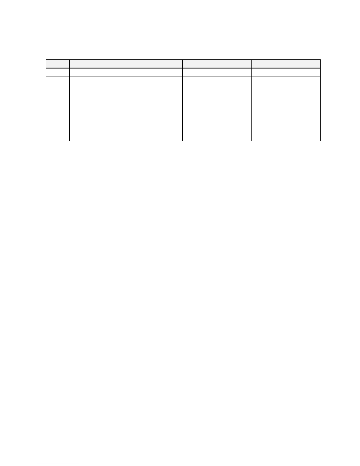
Revision History Table
No.
Revision contents
The date of issue
Engineering sheet No.
1.
Initial release of Quick Reference Guide
Oct. 2016
NT355AX
Outside of this table, only revised spelling mistakes, omitted words, and error in writing will be
changed without notice.
Page 4
SAFETY PRECAUTIONS
SAFETY PRECAUTIONS
Carefully read this QRG and all of the warning labels attached to the inverter before installing,
operating, maintaining, and inspecting. Safety precautions are classified into “Warning” and
“Caution” in this QRG.
:Indicates a potentially hazardous situation which, if not avoided, can result
in serious injury or death.
:Indicates a potentially hazardous situation which, if n ot avoided, can result in minor
to moderate injury, or serious damage to the product
The situation described in may, if not avoided, lead to serious adverse results.
Important safety measures are described in CAUTION (as well as WARNING) so be sure observe them.
Notes are described in this QRG in “NOTE.” Carefully read the contents and follow them exactly.
CAUTION
In all the illustrations in this QRG, covers and safely devices are occasionally removed to describe
the details. When the inverter is operated, make sure that the covers and safety devices are placed
as they were specified originally and operate it according to the instruction manual of the inverter.
WARNING
CAUTION
CAUTION
Page 5
SAFETY PRECAUTIONS
WARNING
Wiring:
Wiring work shall be carried out by electrical experts.
Otherwise, there is a danger of electric shock, fire and/or damage of product.
Implement wiring after checking that the power supply is off.
Otherwise, there is a danger of electric shock and/or fire.
Be sure not to operate electrical equipment with wet hands.
Otherwise, there is a danger of electric shock and/or injury.
Do not damage cables caused by stress or sandwich.
Otherwise, there is a danger of electric shock.
Operating:
Please do not open the inverter’s case or optional case when the power supply is on and please
do not carry out the following operations when the power supply is on.
(1) Please do not touch the inside (ex. terminal parts).
(2) Please do not check the internal signal.
(3) Please do not put on or take off the internal wiring and connector.
Otherwise, there is a danger of electric shock and/or fire.
Do not touch the conductive parts such as the internal PCB, terminals or connector while power
is being supplied.
Otherwise, there is a danger of electric shock.
Be sure not to remove this product while inverter is powered ON.
Otherwise, there is a danger of electric shock and/or fire.
Maintenance, Inspection and Part Replacement:
Wait at least 10 minutes after turning off the input power supply before performing maintenance
and inspection.
(Confirm that charge lamp on the inverter is off, check the direct current voltage between P-N
terminals and confirm it is less than 45V)
Otherwise, there is a danger of electric shock.
Make sure that only qualified persons perform maintenance, inspection, and part replacement.
Before starting the work, remove metallic objects from your perso n (wristwatch, bracelet, etc.). Be
sure to use tools protected with insulation.
Otherwise, there is a danger of electric shock and/or injury.
Please do not carry out insulation resistance (megger) and voltage proof test.
Otherwise, there is a danger of electric shock and/or a possibility that the product will get
damaged.
NOTE:
Never disassemble / repair / modify the unit.
Otherwise, there is a danger of electric shock and/or injury.
Page 6
SAFETY PRECAUTIONS
CAUTION
Installation:
Be sure not to let foreign matter such as wire clippings, spatter from welding, metal shavings, dust
etc. enter the unit.
Otherwise, there is a danger of fire.
Be sure to fix the inverter to this product with an attached fixed screw.
Otherwise, there is a danger of a connection error.
Be sure to fasten the screws connecting the signal wire inside of this product. Check for any
loosening of screws.
Otherwise, there is a danger of a connection error.
Be sure that all cable connector screws are tightened to the torque specified in the relevant
manuals.
Otherwise, tightening torque may result in malfunction.
In order to prevent damage caused by static electricity, Please remove the static electricity of the
body touch the nearby metal before touching this product.
Otherwise, there is a possibility that the product will get damaged.
Please do not carry out insulation resistance (megger) and voltage proof test.
Otherwise, there is a danger of electric shock and/or a possibility that the product will get
damaged.
Be careful of the followings.
- When removing WJ-PN, do not pull the PROFINET DP cable.
- When mounting WJ-PN, be sure that the PROFINET DP cable is not pinched.
- When mounting WJ-PN, be careful about burrs of the break-outs on the inverter.
Otherwise, there is a possibility that the product will get damaged.
Wiring:
Be sure to fasten the screws so they will not come loose.
Otherwise, there is a danger of a connection error.
Be sure that all cable connector screws are tightened to the torque specified in the relevant
manuals.
Otherwise, tightening torque may result in malfunction.
Operation:
Check rotary direction, abnormal motor noise and vibrations during operation.
Otherwise, there is a danger of injury to personnel and/or machine breakage.
Check the Inverter's EzSQ program and its interaction with the PROFINET IO controller before
actually running it on the Inverter.
Otherwise, there is a danger of injury to personnel and/or machine breakage.
If an unexpected phenomenon happens, please do not touch the product, the inverter and cable.
Otherwise, there is a danger of injury to personnel.
Page 7
Chapter 1 Introduction
1
1.1 Check at the time of purchase
Make sure to treat the product carefully to prevent shock and vibration while unpacking and not to
damage the connector to connect WJ-PN and a inverter.
Confirm that the product is the one you ordered, that there are no defects, and that there was no
damage during transportation.
Contents:
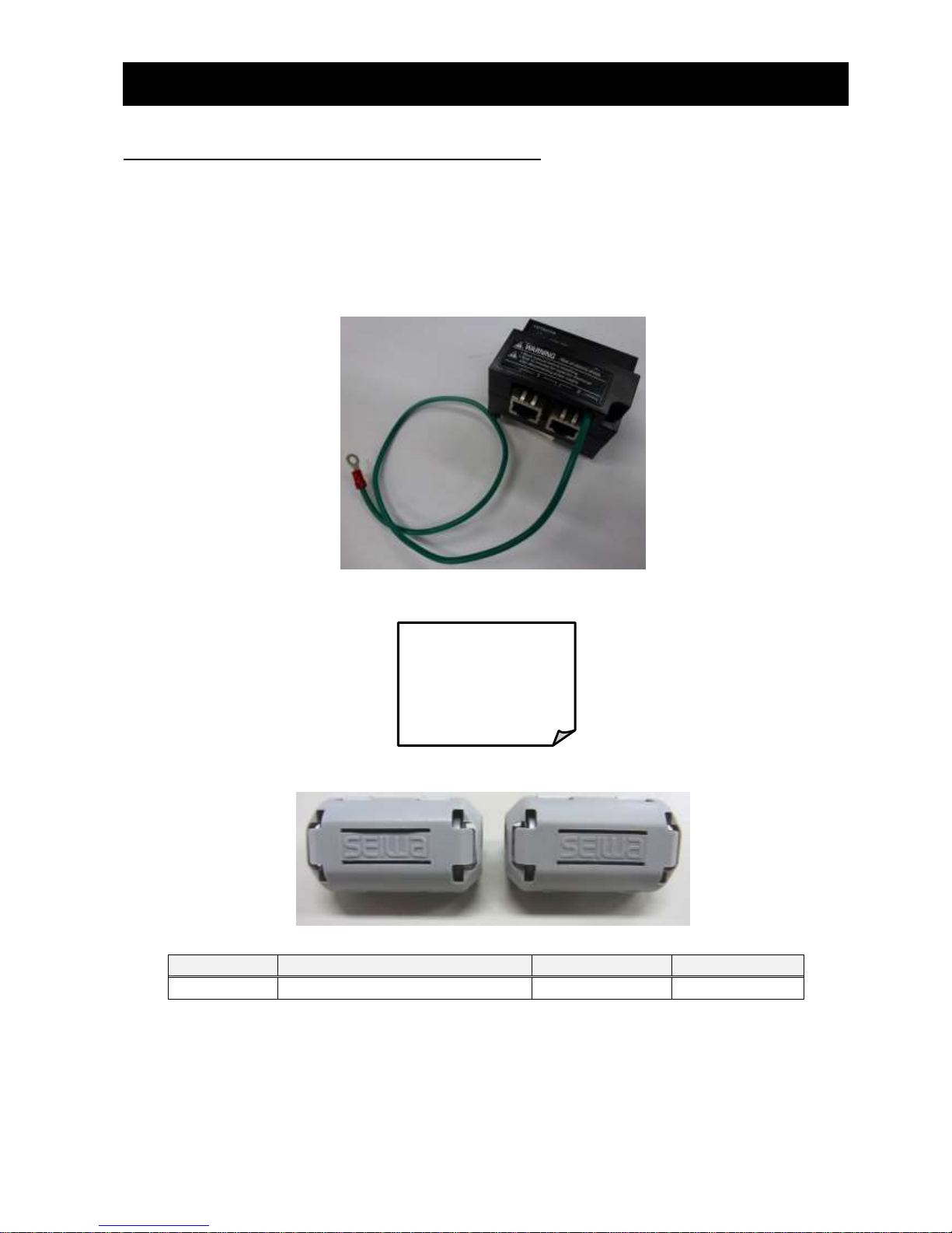
(1) WJ-PN (PROFINET Communication option): 1 piece
(2) Basic Manual: 1 copy.
(3) Ferrite core: 2 pieces.
Specifications (recommended)
Name
Manufacturer
Model
Inner diameter
Ferrite core
SEIWA ELECTRIC MFG. Co., Ltd.
E04SR200935A
9 [mm]
If you find any problems, contact your sales agent immediately.
Please keep the original packing box/material and return all of them to investigate them by ou r side.
Basic Manual
Page 8
Chapter 1 Introduction
2
1.2 Inquiry of the product and warranty for the product
1.2.1 Required information for product inquiry
If an inquiry of breakage, a question, damage etc. is required, please relay the following information
about WJ200 / WL200 and WJ-PN to the supplier that you ordered from or the nearest Hitachi
Distributor.
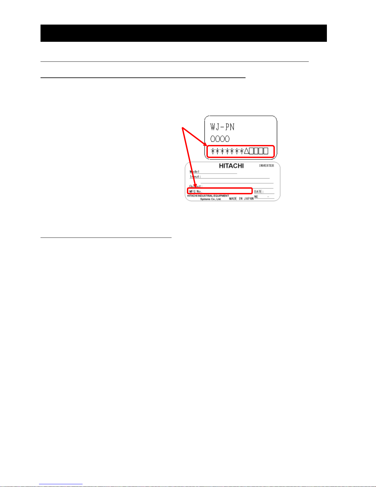
(1) Type (WJ200 / WL200 and WJ-PN)
(2) Manufacturing number (MFG No.)
Please refer to the lateral specifications labels
(the figure shows an example.) on the side.
(3) Date of purchase
(4) Contents of inquiry
- Damaged parts and its condition etc.
- Parts in question and their contents etc.
In order to shorten down time, utilizing a replacement unit is recommended.
1.2.2 Warranty of the product
The warranty period under normal installation and handling conditions shall be 2 years from the
date of manufacture, or 1 year from the date of installation, whichever occurs first. The warranty shall
cover the repair or replacement, at Hitachi's sole discretion, of ONLY the product that was installed.
1. Service in the following cases, even within the war ranty period, shall be charged to the purchaser:
a. Malfunction or damage caused by miss-operation or modification or improper repair
b. Malfunction or damage caused by a drop after purchase and transportation
c. Malfunction or damage caused by fire, earthquake, flood, lightening, abnormal input voltage,
contamination, or other natural disasters
2. When service is required for the product at your work site, all expenses associated with field
repair shall be charged to the purchaser.
Always keep this manual handy; please do not lose it. Please contact your Hitachi distributor to
purchase replacement or additional manuals.
Page 9

Chapter 2 Outline
3
2.1 Outline of product
WJ-PN is an interface option of PROFINET communication for WJ200 / WL200. WJ-PN allows
controlling, monitoring and parameterization of WJ200 / WL200 via the PROFINET network.
PROFINET is an open, digital communication system. PROFINET is anchored in the international
standards IEC 61158 and IEC 61784.
WJ-PN supports the application profile PROFIdrive version 4.2. This profile defines device behavior
and the access procedure to drive data for electric drives on PROFINET or PROFINET.
(1) PROFINET
WJ-PN supports PROFINET IO Ver.2.32.
The conformance class of WJ-PN is B.
(2) Cyclic communication
The PROFINET IO controller manages the PROFINET network, and performs PROFINET IO device
status monitoring and data exchange with the PROFINET IO devices.
The format of communication data conforms to PROFIdrive.
Output data (to PROFINET IO device) : operation command, target value, etc.
Input data (to PROFINET IO controller) : operation status, present value, etc.
(3) Setting the inverter parameters
You can set the inverter parameters by using acyclic communication of the PROFINET.
The procedure to access parameters conforms to PROFIdrive.
Page 10
Chapter 2 Outline
4
2.2 About optional correspondence of WJ200 / WL200
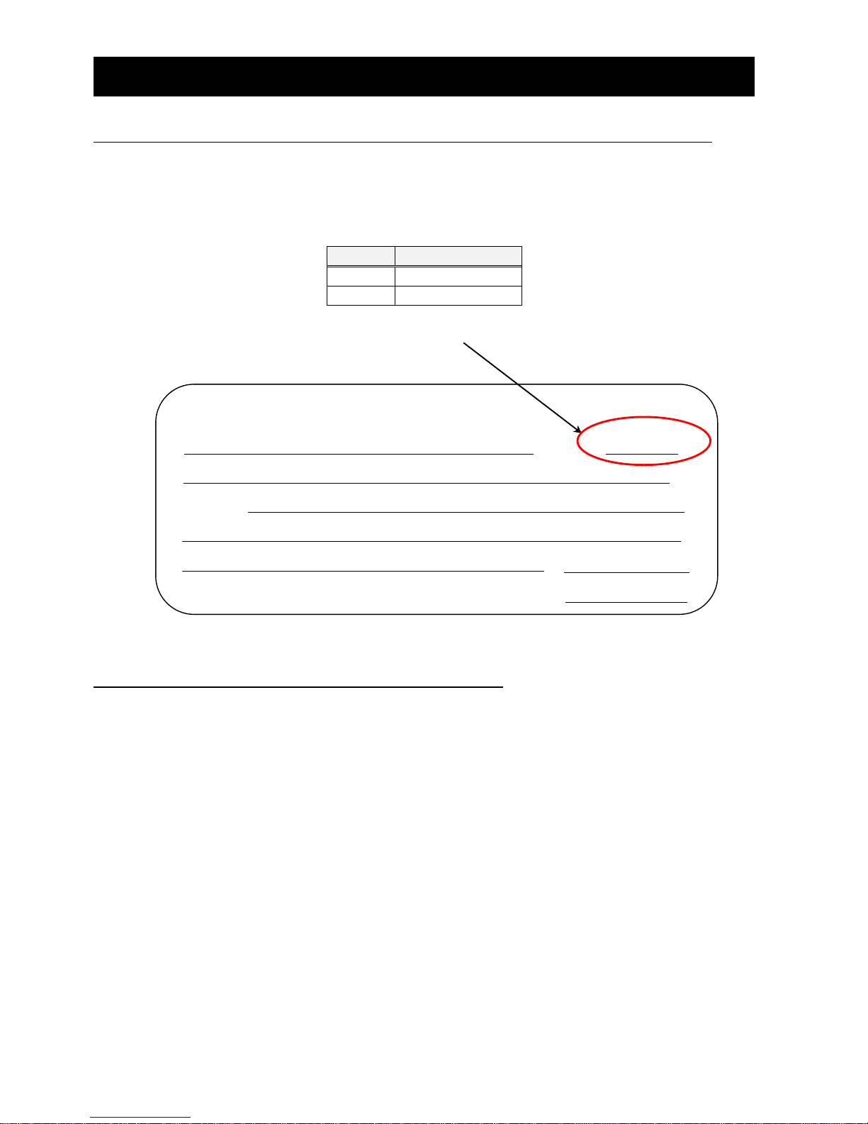
You can attach WJ-PN to all models of WJ200 / WL200. However, it may not support WJ-PN
depending on the product version. Please refer to the inverter specifications label on the side and
check its version (it is mentioned in the top right corner) on specifications label. (The figure shows an
example.)
WJ200/WL200 of the version listed in the table below is compatible with WJ-PN.
Series
Version
WJ200
Ver.2.4 or later
WL200
Ver.1.0E or later
2.3 About limitations of using WJ-PN
When you use WJ-PN, be aware of the following limitations:
- Modbus communication is not usable.
- Functional safety (STO) certification of the inverter becomes ineffective.
Please confirm the version.
HITACHI
Model:
Input:
Output:
MFG No.
MADE IN JAPAN
NE -
INVERTE
DATE:
HITACHI INDUSTRIAL EQUIPMENT
Systems Co., Ltd.
Ver.2.4
Page 11
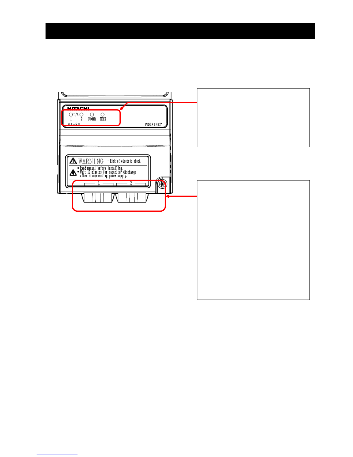
Chapter 3 Appearance
5
3.1 Appearance and each part name
The following is the external description of WJ-PN. For more information about LEDs and connectors,
please refer to the page mentioned.
LEDs:
These LEDs describe PROFINET states.
From left side:
- L / A 1
- L / A 2
- COMM
- ERR
Connectors:
You can connect the option to the
PROFINET network via these
connectors. Connector type is RJ-45,
electrical characteristics conform to
IEEE802.3 standard.
The left side is port 1, and the right side
is port 2.
NOTE:
Please fix the connected PROFINET
cables to prevent mechanical failure by
the vibration/gravity.
Install the ferrite core (included in
shipment) on the LAN cables (both port
1 and 2) near the connectors.
Page 12
Chapter 3 Appearance
6
3.2 Summary of all parts
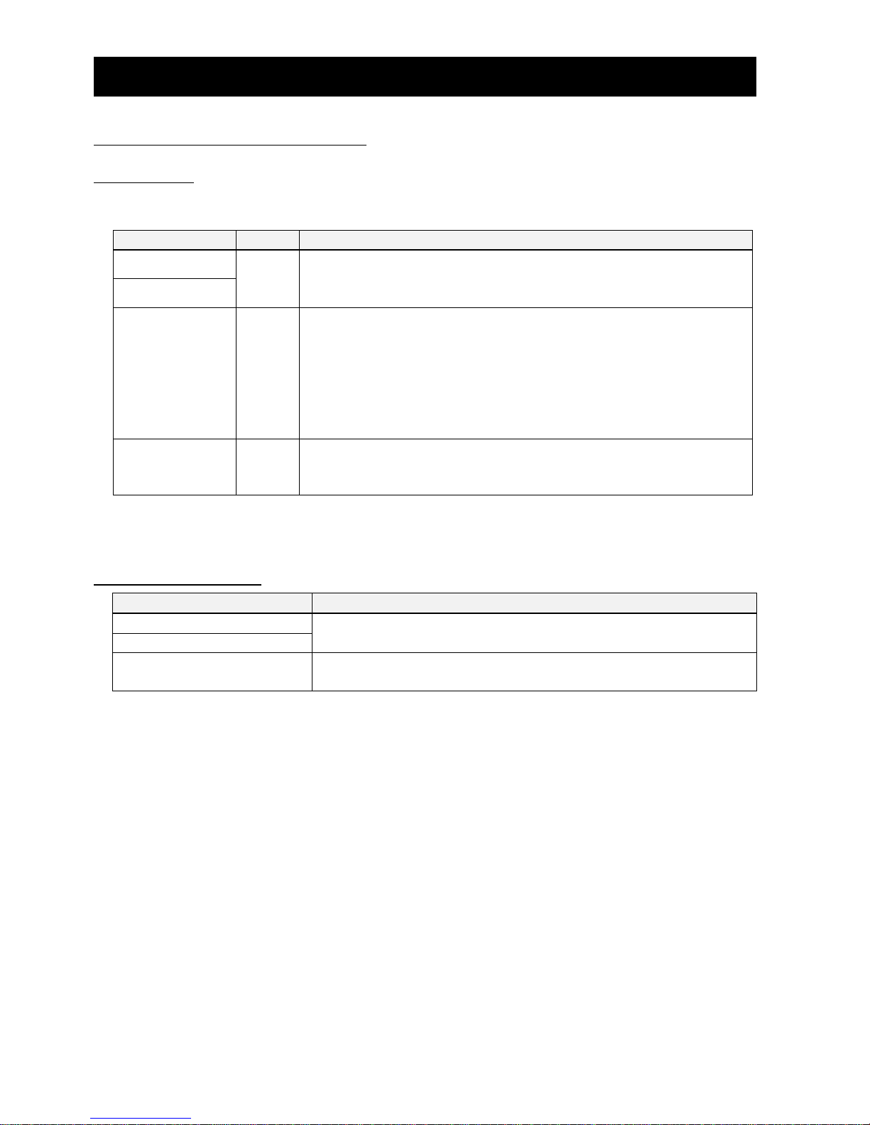
3.2.1 LED
The summaries of LED, the setting switch and the connector are as follows.
Please refer to “9.1 Status indicator explanations a nd error handling” for details.
Name
Color
Description
L / A 1
Green
ON : Link is established.
Blinking : Activity.
OFF : No link is established.
L / A 2
COMM
Green
ON : WJ-PN is communicating with PROFINET IO controller by
the set telegram.
Blinking : WJ-PN starts communicating with PROFINET IO
controller, and is setting to communicate with
PROFINET IO controller by the set telegram.
OFF : WJ-PN doesn’t communicate with PROFINET IO
controller by the set telegram.
ERR
Red
ON : WJ-PN detects hardware error.
Blinking : WJ-PN detects communication timeout.
OFF : WJ-PN doesn’t detect any errors.
COMM and ERR LED are switched on from power on until WJ-PN has finished startup.
3.2.2 Connector
Name
Description
PROFINET connector port 1
This is connected to the PROFINET network.
PROFINET connector port 2
Grounding cable
Wire the ground cable.
NOTE: Please be sure to do it.
Please refer to Chapter 5 ‘Wiring, Connecting’ for the specifications and the wiring.
Page 13
Chapter 4 Attachment
7
4.1 Before attaching WJ-PN
First of all, please confirm that the inverter’s main power supply is OFF. Next, please confirm that
the 4-digit 7-segment display turns off the light.
Perform the main circuit wiring of the power line (power supply, motor, grounding, BRD), and do the
control circuit wiring of the signal line. After wiring on main and control circuit is completed, please
confirm that the inverter works normally before attaching WJ-PN.
Please refer to Chapter 2 Inverter Mounting and Installation' of the WJ200 / WL200 instruction
manual for the wiring.
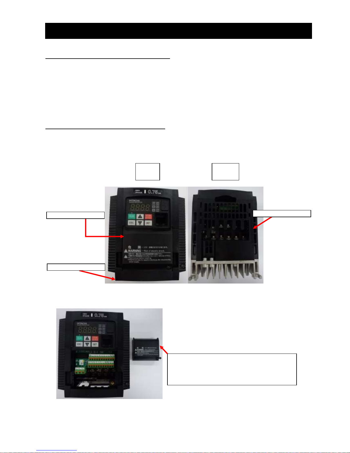
4.2 Attachment procedure
The connection procedure of WJ-PN as follows.
(An example: in the case of WJ200-004LF)
(Main circuit electric wiring and the control circuit electric wiring are omitted.)
The initial state.
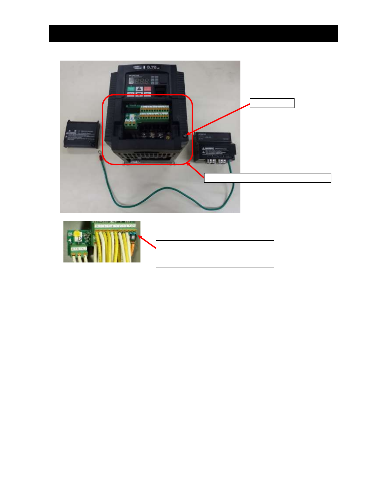
Please remove the optional board cover.
Optional board cover
Terminal block cover
Housing partition
Front
view
Bottom
view
Removed optional board cover
(Please carefully store an optional board cover.
When the WJ-PN breaks down, it will be necessary
for the temporary driving.)
Page 14
Chapter 4 Attachment
8
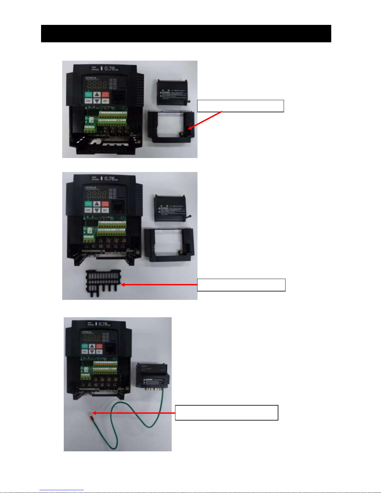
Please remove the terminal block cover.
Please remove the housing partition.
Please wire the grounding cable.
Removed terminal block cover
Removed housing partition
Wire the cable.
NOTE: Please make sure to do it.
Page 15
Chapter 4 Attachment
9
Reattach the housing partition and terminal cover. (Option board cover is not used in this case.)
NOTE: in above pictures, the length of ground cable is not suitable. To avoid pulling the cable
unintentionally, you need to cut the ground cable to an appropriate length for the distance to the
inverter’s grounding terminal and the size of the terminal block, and crimp the cable to the crimp
terminal before using.
Please put the all wires beneath this
option properly (to prevent rising by
those wiring in future.)
Fixed screw
Reattached housing partition and terminal
Page 16
Chapter 4 Attachment
10
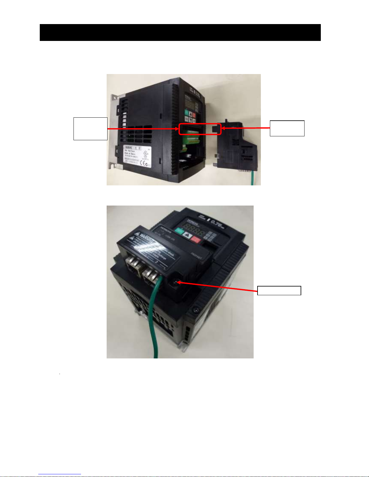
Lift the WJ-PN, and, please attach the installation connector (for WJ-PN) carefully and slowly from
the front of the installation connector for the option of the WJ200 / WL200. Be careful to make the
connectors straight and not to break the hooks
Fix the option with the screws.
Please check the connection state of the WJ-PN and the WJ200 / WL200 inverter via the connector.
When the connection state of the connector is bad, the Option error (inverter communication error,
code: E6*, please refer to Chapter 9) may occur after supplying power to the inverter. Or, because the
inverter cannot recognize an option, normal communication may not be carried out.
NOTE: Please install the inverter in a grounded metal cabinet.
Fixed screw
Option
connector
Option
board
connector
Page 17
Chapter 5 Wiring, Connecting
11
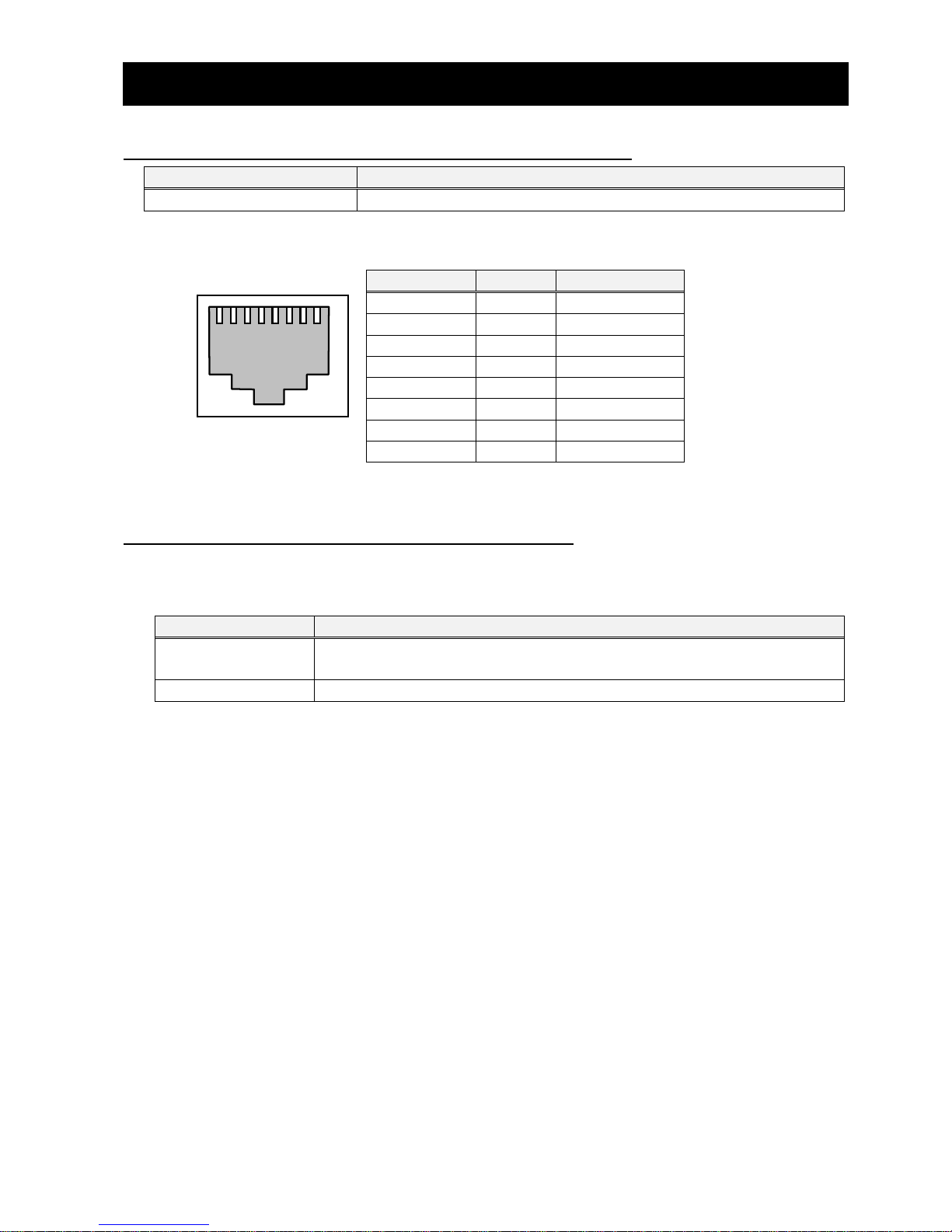
5.1 Specification of PROFINET connector
Connector type
Description
RJ-45
Screwless type, the flange is with a screw
The Appearance and the wiring are the following.
5.2 Specification of PROFINET cable
If an Ethernet cable of category 5e or higher is used, communications will be possible even if the
cable is not shielded. However, we recommend the following cable to ensure sufficient noise
immunity.
Name
Description
Twisted-pair cable
100BX-TX supported (category 5e or higher)
STP cable (straight or cross allowed)
RJ-45 connector
Category 5e or higher, shielding supported
IN
/OUT
1
8
Pin number
Symbol
Type of signal
1
TD+
Send data+
2
TD-
Send data-
3
RD+
Receive data+
4
-
5
- 6
RD-
Receive data-
7
-
8
-
Page 18
Chapter 5 Wiring, Connecting
12
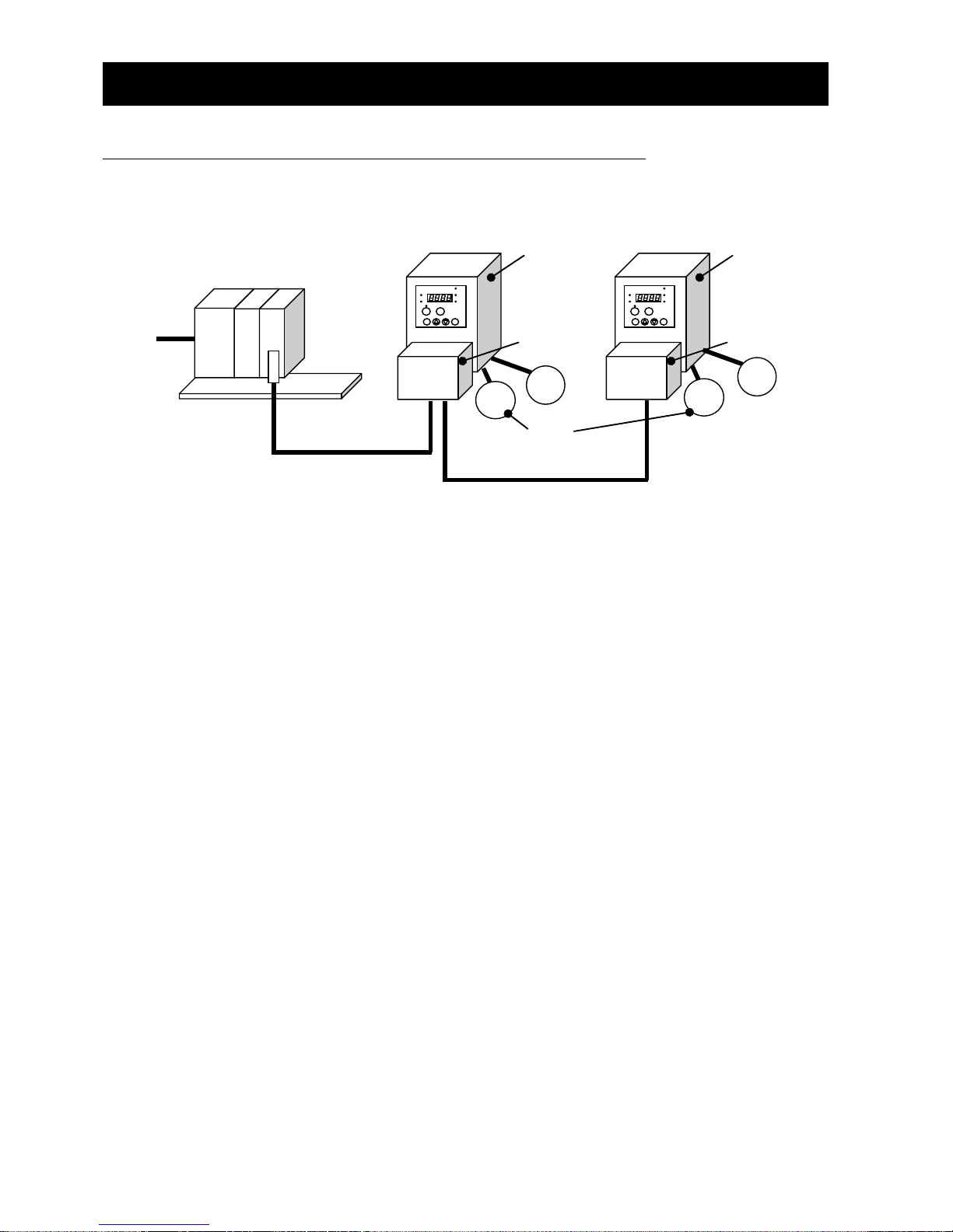
5.3 A system configuration of the PROFINET
The following sketch is an example of PROFINET system configuration.
(1) When you wire the signal line to the PROFINET connection connector, take the connector off
WJ-PN and please wire it in the state that cut the communication p ower supply. WJ-PN may be
damaged by false contact.
(2) Network cables should be fixed without tension. Cables fixed under tension have the potential of
causing a communication fault by removing a connector.
(3) The communication line and the power line should wire the position that they separated as
much as possible. When the position of the power line is near the communication line, it may not
communicate by a noise.
(4) Ensure external emergency stop measures are taken to stop the inverter, in the event of a
network fault.
(a) Break the power supply of the Inverter when the network PROFINET IO controller detects a
communication fault.
(b) When the PROFINET IO controller detects a communication fault, turn on the intelligent input
terminal which would be allocated (FRS), (RS) and/or (EXT) function.
(c) Setting command P045 (Inverter action on communication error). Regarding this setting, the
inverter is tripped, deceleration or free run stop when it detects a communication fault by itself.
(Factory initialization of command P045 (Inverter action on communication error) is tripped.
e.g. WJ200 / WL200 becomes the trip when a PROFINET IO controller detects a
communication fault when WJ200 / WL200 runs by an order from the PROFINET.)
-About SAFETYWhen WJ200 / WL200 is used with Dip-Switch in the position to activate functional safety and
communication PROFINET IO controller unit detects the communication error, please turn “OFF (to
interrupt the output)” GS1 signal (intelligent input #3) and GS2 (intelligent input #4.) It is to be
noticed that approval by third party for “STO” function is void even if the safety function is activated
with Dip-Switch in the position to select functional safety (STO) when WJ-PN is attached to WJ200 /
WL200.
WJ200 / WL200
WJ-PN
PROFINET cable
M
PROFINET IO
controller
~
Power
supply
WJ200 / WL200
WJ-PN
AC power supply
(Three or single phase)
M
~
PROFINET cable
Page 19
Chapter 5 Wiring, Connecting
13
For more details, please refer to the instruction manual of WL200 / WL200.
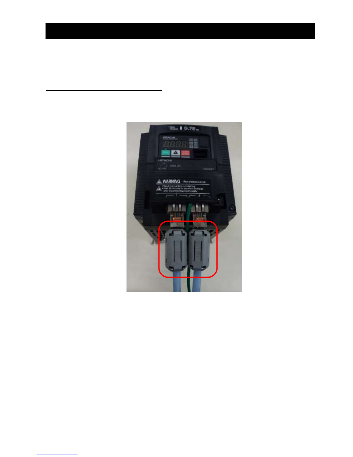
5.4 Install the ferrite core
Install the ferrite core (included in shipment) on the LAN cables (both IN and OUT) near the
communications connectors. (If the communications cable on the OUT side is not connected, install
the ferrite core for the IN side only.)
NOTE: Please fix the connected LAN cables.
Page 20

Chapter 6 Operation from PROFINET
14
6.1 Precautions for use
Check the Inverter settings for proper Inverter behavior before actually operating the Inverter
remotely via the network.
The product will be used to control an adjustable speed drive connected to high voltage sources
and rotating machinery that is inherently dangerous if not operated safely. Interlock all energy sources,
hazardous locations, and guards in order to restrict the exposure of personnel to hazards. The
adjustable speed drive may start the motor without warning. Signs on the equipment installation must
be posted to this effect.
A familiarity with auto-restart settings is a requirement when controlling adjustable speed drives.
Failure of external or ancillary components may cause intermittent system operation, i.e., the system
may start the motor without warning or may not stop on command. Improperly designed or improperly
installed system interlocks and permissions may render a motor unable to start or stop on command.
6.2 Setup of the WJ200 / WL200 for commissioning
Before commissioning, prepare the Inverter and WJ-PN by following the setting example below.
6.2.1 Setting of the inverter mode (When WJ200 / WL200 is
connected to standard IM.)
Set the Inverter mode to Std. IM by first setting b171 = 1 and then b180 = 1.
When WJ200 / WL200 is connected to PM, you need to set b171 = 3.
6.2.2 Initialization of the inverter
First of all, please set b084 to 04(Clears trip history and initializes all parameters and EzSQ
program), next set b085 to 01(area A), and then set b094 to 00(All parameters), and next set b180 to
01(Perform initialization), and then initialization of the inverter will be started.
6.2.3 Constant Torque mode/Variable Torque mode selection
In case of WJ200, Set b049 to 00 (b049 = 00: Constant Torque mode).
In case of WL200, you don’t need to set b049 because WL200 supports only Constant Torque
mode and doesn’t support b049.
After the above-mentioned setting is completed, please set the parameter A001, A002, A004, A038,
A039, A093, b031, C001 - C007, C042, C043, C102, P044, P045, P160 - P179 and P200 according
to the table in “7.2: Parameter setting of WJ200 / WL200”. When you set parameters with Operator
or PC (ProDriveNext), you need to turn OFF the inverter. After the power supply of the inverter
becomes OFF, please turn ON the inverter and check that WJ-PN communicates by PROFINET.
Please refer to data example of the WJ200 / WL200 operating in the PROFINET communication
from the next page.
Page 21
Chapter 6 Operation from PROFINET
15
6.3 Operation with frequency command [Hz]
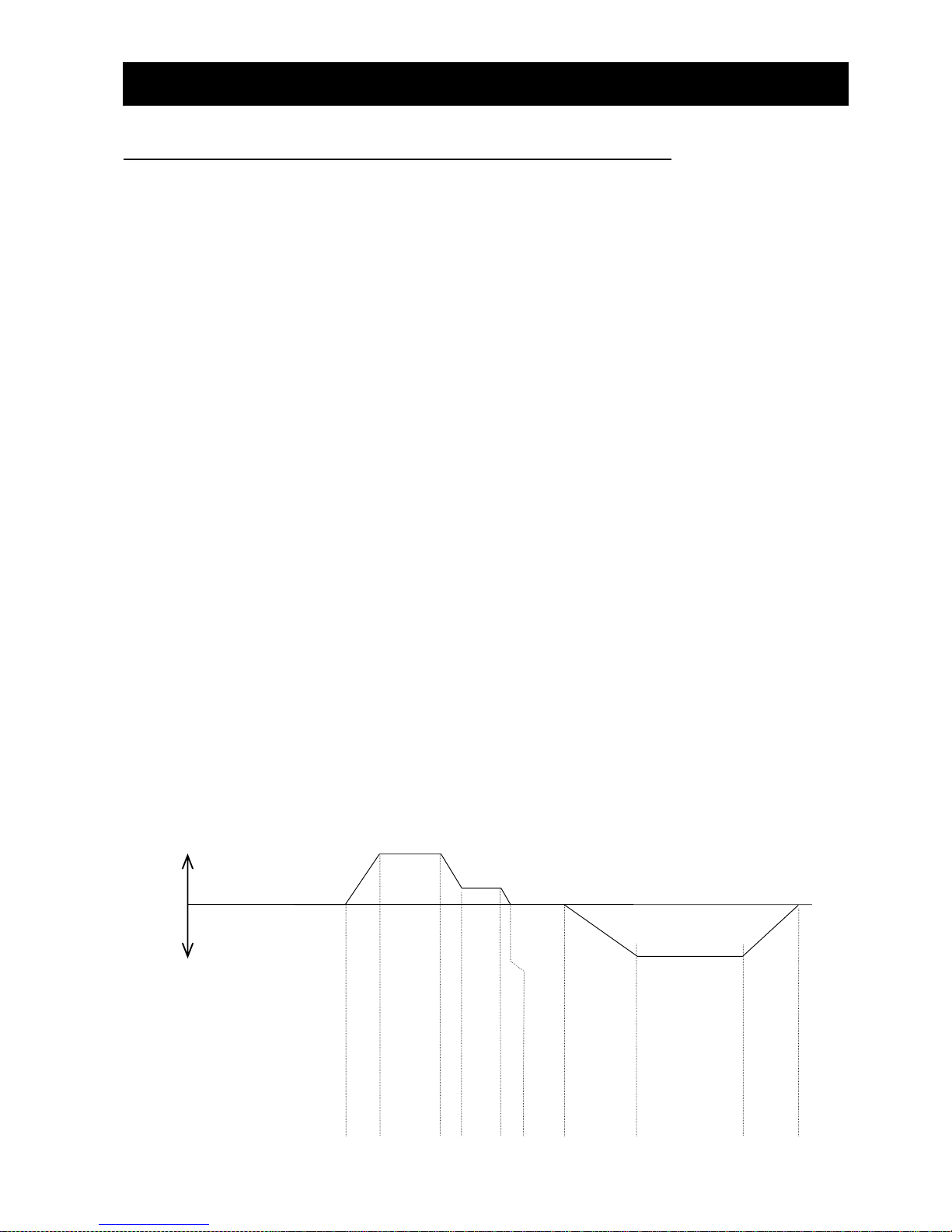
Please refer to the instruction manual of the PROFINET IO controller about the way of using it.
For a detailed description of the PROFINET communication, please refer to Chapter 8. The following
is an example of operation with the Standard telegram 1 in the PROFINET communication and setting
A004 to 50 [Hz].
STW1 is the control word. ZSW1 is the status word. NSOLL_A means the setting of output frequency.
NIST_A means the actual output frequency.
[Setpoint (PROFINET IO controller -> PROFINET IO device)]
① Setting STW1 to 0x0406.
② Setting STW1 to 0x0407.
③ Setting STW1 to 0x047F.
④ Setting NSOLL_A to 0x4000 (100%).
⑤ Setting NSOLL_A to 0x1000 (25%).
⑥ Setting NSOLL_A to 0x0 (0%).
⑦ Setting NSOLL_A to 0xC000 (-100%).
⑧ Setting NSOLL_A to 0x0 (0%).
[Actual value (PROFINET IO device -> PROFINET IO controller)]
⑨ Stopping state, PROFIdrive transition to “Ready For switching On”.
⑩ Stopping state, PROFIdrive transition to “Switching On”.
⑪ Driving with 0x0 (0% : 0[Hz]) state, PROFIdrive transition to “Operation”.
⑫ Accelerating in forward direction, “XXXX” indicates NIST_A during acceleration.
⑬ Driving at a constant speed state, NIST_A is equal to 0x4000 (100% : 50[Hz]).
⑭ Deceleration state, “XXXX” indicates NIST_A during deceleration.
⑮ Driving at a constant speed state, NIST_A is equal to 0x1000 (25% : 12.5[Hz]).
⑯ Deceleration state, “XXXX” indicates NIST_A during deceleration.
⑰ Driving at a constant speed state, NIST_A is equal to 0x0 (0% : 0[Hz]).
⑱ Accelerating in reverse direction, “XXXX” indicates NIST_A during deceleration.
⑲ Driving at a constant speed state, NIST_A is equal to 0xC000 (-100% : -50[Hz]).
⑳ Deceleration state, “XXXX” indicates NIST_A during deceleration.
○21 Driving at a constant speed state, NIST_A is equal to 0x0 (0% : 0[Hz]).
②
0x0407
0
⑩
0x0233
0
⑮
0x0337
0x1000
-50[Hz]
10[Hz]
50[Hz]
Setpoint
STW1
NSOLL_A
Actual value
ZSW1
NIST_A
Reverse
Forward
④
0x047F
0x4000
⑫
0x0237
XXXX
⑤
0x047F
0x1000
⑭
0x0237
XXXX
⑥
0x047F
0
⑯
0x0237
XXXX
③
0x047F
0
⑪
0x0237
0
①
0x0406
0
⑨
0x0231
0
⑦
0x047F
0xC000
⑱
0x0237
XXXX
⑲
0x0337
0xC000
⑧
0x047F
0
⑳
0x0237
XXXX
○
21
0x0237
0
⑬
0x0337
0x4000
⑰
0x0237
0
Page 22
Chapter 7 Setting
16
7.1 Installation of the GSDML File
It is necessary to install the GSDML File to your PC tool (Engineering tool) of PROFINET IO controller
to use WJ-PN. GSDML file is a file that contains specific information of the PROFINET IO devices.
Please inquire to the nearest business contact about the GSDML file.
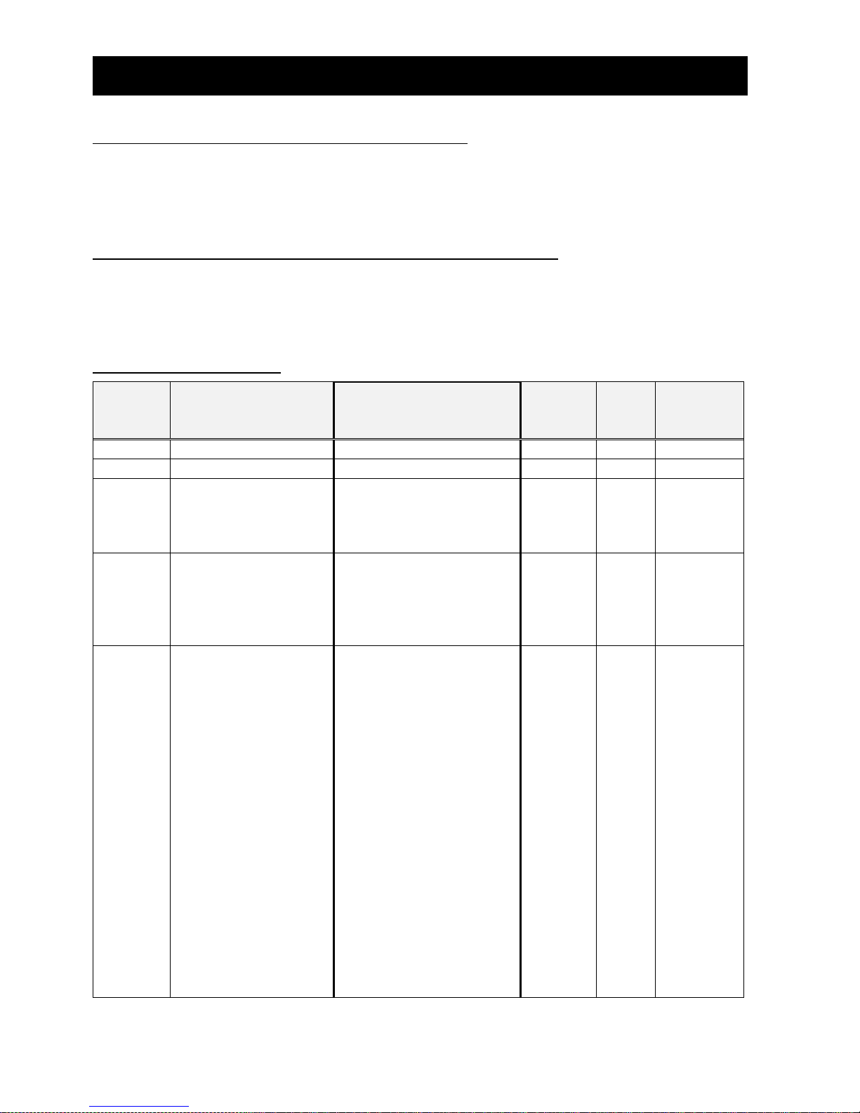
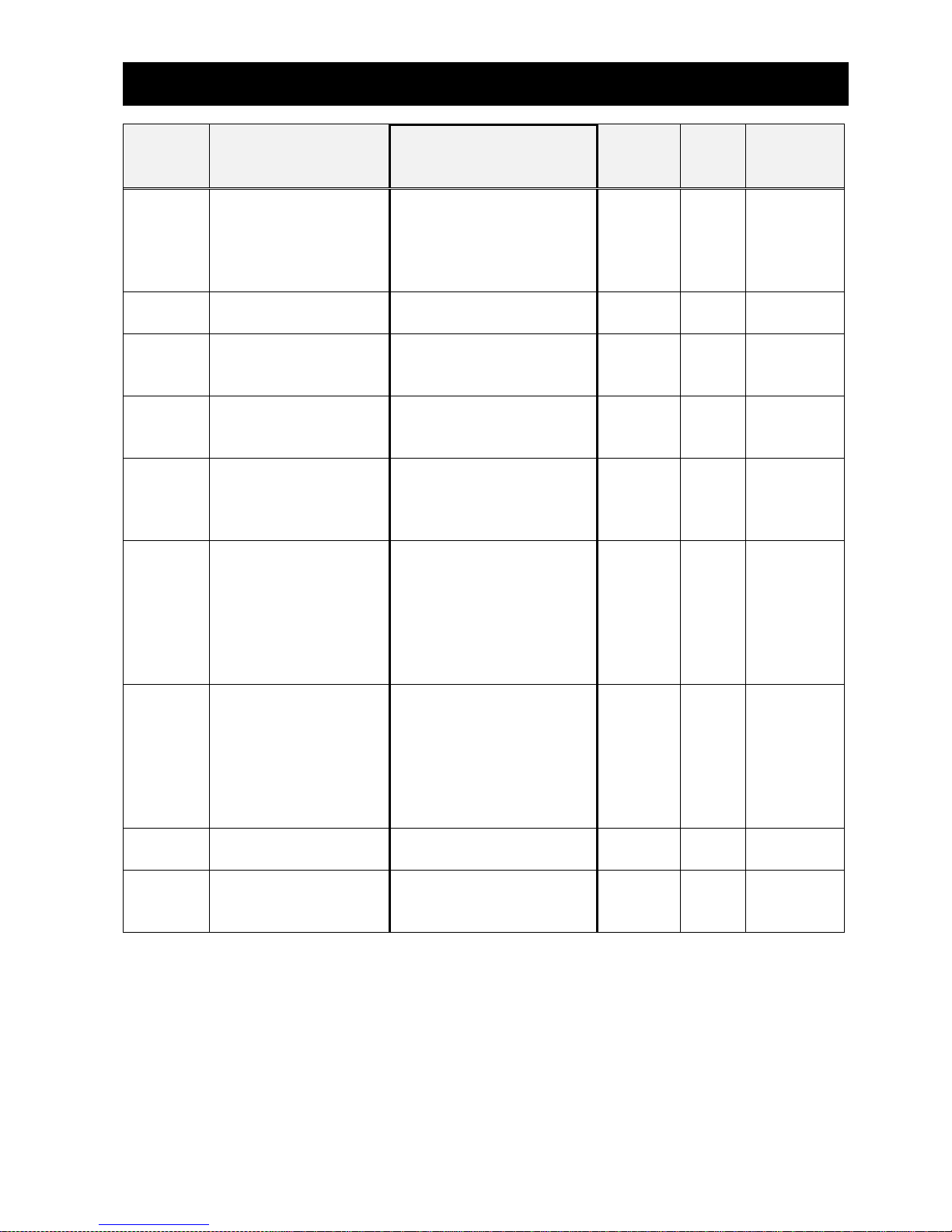
7.2 Parameter settings of WJ200 / WL200
WJ-PN needs the parameter settings of WJ200 / WL200, which shows the following table.
Concerning the operating of the system, it is necessary to refer to the instruction manual of the
inverter and the QRG of this option. Please perform appropriate settings as needed.
Parameter settings
Function
code
Name
Value and description
Default
Run
mode
edit
High level
access
mode
A001
Frequency source
04: option
02 × ×
A002
Run command source
04: option
02 × ×
A004
Maximum frequency
Optional
Settable from the base
frequency to 400(580) Hz
60.0
×
×
A038
Jog frequency
Optional
Defines limited speed for
jog, range is from start
frequency to 9.99 Hz
6.00
○
○
A039
Jog stop mode
Optional
Define how end of jog
stops the motor; six
options:
00 : Free-run stop (invalid
during run)
01 : Controlled
deceleration (invalid
during run)
02 : DC braking to stop
(invalid during run)
03 : Free-run stop (valid
during run)
04 : Controlled
deceleration (valid during
run)
05 : DC braking to
stop(valid during run)
04 × ○
Page 23
Chapter 7 Setting
17
Function
code
Name
Value and description
Default
Run
mode
edit
High level
access
mode
A093
Deceleration time (2)
Optional
Duration of 2nd segment
of deceleration, range is:
0.00 to 3600 sec.
10.00
○
○
b031
Software lock mode
selection
10: High level access
including b031
01 × ○
C001
-
C007
Input [1-7] function
Except 06: JG
× ○
C005
Input [5] function
09: 2CH, Frequency
output uses 2nd-stage
deceleration value.
09 × ○
C006
Input [6] function
83: HLD, Frequency
output uses 2nd-stage
acceleration and
deceleration values.
18 × ○
C042
Frequency arrival
setting for acceleration
Optional
Sets the frequency arrival
setting threshold for the
output frequency during
acceleration, range is 0.0
to 400.0(580.0) Hz
0.0 × ○
C043
Frequency arrival
setting for deceleration
Optional
Sets the frequency arrival
setting threshold for the
output frequency during
deceleration, range is 0.0
to 400.0(580.0) Hz
0.0 × ○
C102
Reset selection
03: Clear the memory only
related to trip status
00 ○ ○
P044
Communication
watchdog timer
(for option)
Optional
Set range is 0.00 to 99.99s
1.00
×
×
Page 24
Chapter 7 Setting
18
Function
code
Name
Value and description
Default
Run
mode
edit
High level
access
mode
P045
Inverter action on
communication error
(for option)
Optional
00 : Tripping
01 : Tripping after
decelerating and
stopping the motor
02 : Ignoring errors
03 : Stopping the motor
after free-running
04 : Decelerating and
stopping the motor
00 × ×
P160
P169
Option I/F
command register
to write 1 to 10
Optional
0x0000 to 0xFFFF
0x0000
○
○
P170
P179
Option I/F
command register
to read 1 to 10
Optional
0x0000 to 0xFFFF
0x0000
○
○
P200
Register Mapping
setting
(WJ200 Ver.3.0 or
later)
00 : Standard Mapping
function disabled
00 × ○
NOTE: You need to set b037 (display limited) to 00 (all parameters displayed).
Page 25

Chapter 7 Setting
19
7.2.1 A001 (Frequency source)
You need to set A001 to 04 in the case of operation WJ200 / WL200 using the PROFINET
communication.
7.2.2 A002 (Run command source)
You need to set A002 to 04 in the case of operation WJ200 / WL200 using the PROFINET
communication.
7.2.3 A004 (Maximum frequency)
The range of frequency that you can monitor or set is from -100% to 100% in PROFIdrive. You need
to set base frequency.
7.2.4 A038 (Jog frequency)
WJ-PN supports Jog mode in Operation status of PROFIdrive. You need to set jog frequency.
7.2.5 A039 (Jog stop mode)
You need to set how the inverter stops. “00” is same as “03” (Free run stop), “01” is same as
“04” (Controlled deceleration), “02” is same as “05” (DC braking to stop).
7.2.6 A093 (Deceleration time (2))
You need to set deceleration time when you use quick stop and C005 to 09 (2ch).
7.2.7 b031 (Software lock mode selection)
You need to set b031 to 10 (changeable mode during driving), if you rewrite the mutable
parameters of the WJ200 / WL200 during operation by the PROFINET communication. If you have not
already set to 10 (changeable mode during driving), it cannot be rewritten even after the rewrite of the
parameters.
7.2.8 C001 - C007 (Input [1-7] function)
You need to set C001 - C007 expect 06 (JG). If you set 06 (JG), Jog mode doesn’t work normally.
7.2.9 C005 (Input [5] function)
You need to set C005 to 09 (2CH), if you use the settings of the two-stage acceleration and
deceleration during the deceleration in the Quick stop of CiA402. WJ200 / WL200 normally
decelerates when you use quick stop of the two-stage acceleration and deceleration without the
above setting.
7.2.10 C006 (Input [6] function)
You need to set C006 to 83 (HLD), if you use the freeze ramp generator function that STW1 bit5 is
OFF. If you don’t set C006 to 83 and STW1 bit5 is OFF, output frequency isn’t freeze.
7.2.11 C042 (Frequency arrival setting for acceleration)
When the output frequency is over the frequency that is set to C042 during acceleration, ZSW1
bit10 becomes ON. If you set C042 to 0, ZSW1 bit10 doesn ’t become ON.
7.2.12 C043 (Frequency arrival setting for deceleration)
Page 26

Chapter 7 Setting
20
When the output frequency is over the frequency that is set to C043 during deceleration, ZSW1
bit10 becomes ON. If you set C043 to 0, ZSW1 bit10 doesn ’t become ON.
7.2.13 C102 (Reset selection)
You need to set 03 (release at tripping) to C102. This parameter decides the WJ200 / WL200’s
action when the reset terminal (RS) is ON.
If you set C102 to 00 (release at ON), 01 (release at OFF), or 02 (enable at tripping), WJ-PN is reset
at reset terminal (RS) input and WJ200 / WL200 displays E60 (option error). If you set 03 (clear
tripping state only), WJ-PN is not reset terminal (RS) input and WJ200 / WL200 can continue driving
after released from tripping.
7.2.14 P044 (Communication watchdog timer (for option))
You need to set P044 to the communication watchdog timer. This communication watchdog timer is
different from the watchdog of PROFINET. This communications watchdog timer starts the time
measuring after the watchdog of PROFINET occurs. In case that the watchdog of PROFINET occurs
and then WJ-PN restarts communicating with PROFINET IO controller within time have been set in
P044, WJ-PN doesn’t detect communication error. If you set P044 to 0, WJ-PB doesn’t monitor
non communication.
7.2.15 P045 (Inverter action on communication error (for
option))
You need to set P045 to inverter action on communication error.
7.2.16 P160 - P169 (Option I/F command register to write 1 to
10)
You need to set P160 - P169 to Modbus register no when you use telegram 103, 104 or 105. Please
refer to “8.12.2 WJ-PN telegram 103 to 105” for details.
7.2.17 P170 - P179 (Option I/F command register to read 1 to
10)
You need to set P170 - P179 to Modbus register no when you use telegram 103, 104 or 105. Please
refer to “8.12.2 WJ-PN telegram 103 to 105” for details.
7.2.18 P200 (Register Mapping setting)
This parameter exists in WJ200 Ver.3.0 or later.
You need to set P200 to 00 when you use WJ-PN.
Page 27
Chapter 7 Setting
21
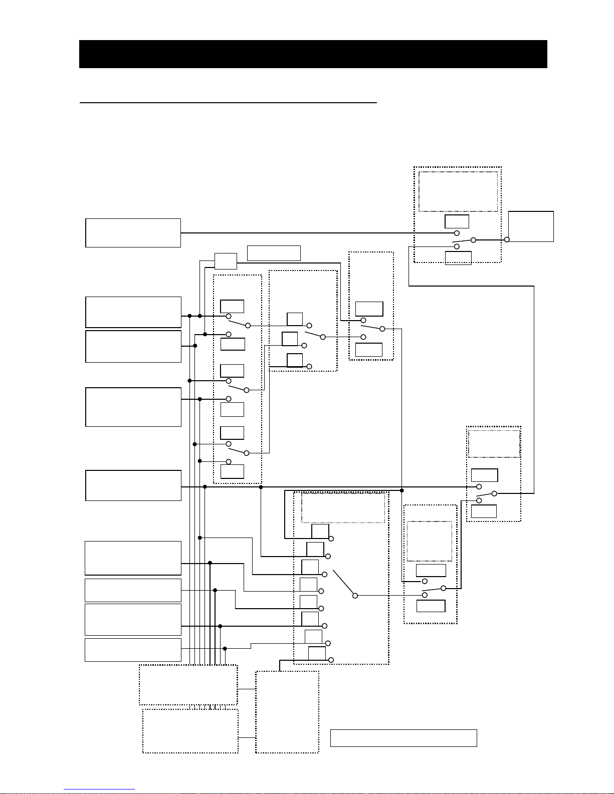
7.3 Selecting of the frequency source
Showing below an association map of the frequency source choice of the WJ200 / WL200 series
inverter (include WJ-PN). Please refer to an instruction manual of the WJ200 / WL200 about the
detailed contents except WJ-PN.
NOTE: Modbus communication is not usable. WL200 doesn’t support Pulse train input [EA].
Frequency
setting
[AT]
terminal
[AT]
selection
A005
Multi-speed
input
CF1-4,SF1-7
Frequency
Source setting
[AT]
terminal
is active
ON
OFF
[O]+[OI]
no
yes
01
02
00
03
04
06
07
10
ON
OFF
Force
terminal
mode
OFF
ON
Operator
control
ON
OFF
Multi-speed
A021-A035
Analog voltage
input [O]
OPE-SR/
OPE-SR mini
[VR]
Digital operator
A020/A220=F001
Modbus
communication
Pulse train
Input [EA]
EzSQ
Frequency calculate function
00
02
03
Input A select for
calculate function
A141
Calculation
symbol
A143
( + )
( - )
( × )
+
Option PCB
Analog current
input [OI]
Input B select for
calculate function
A142
ON
OFF
ON
OFF
Page 28
Chapter 8 PROFINET Specification
22
8.1 PROFINET
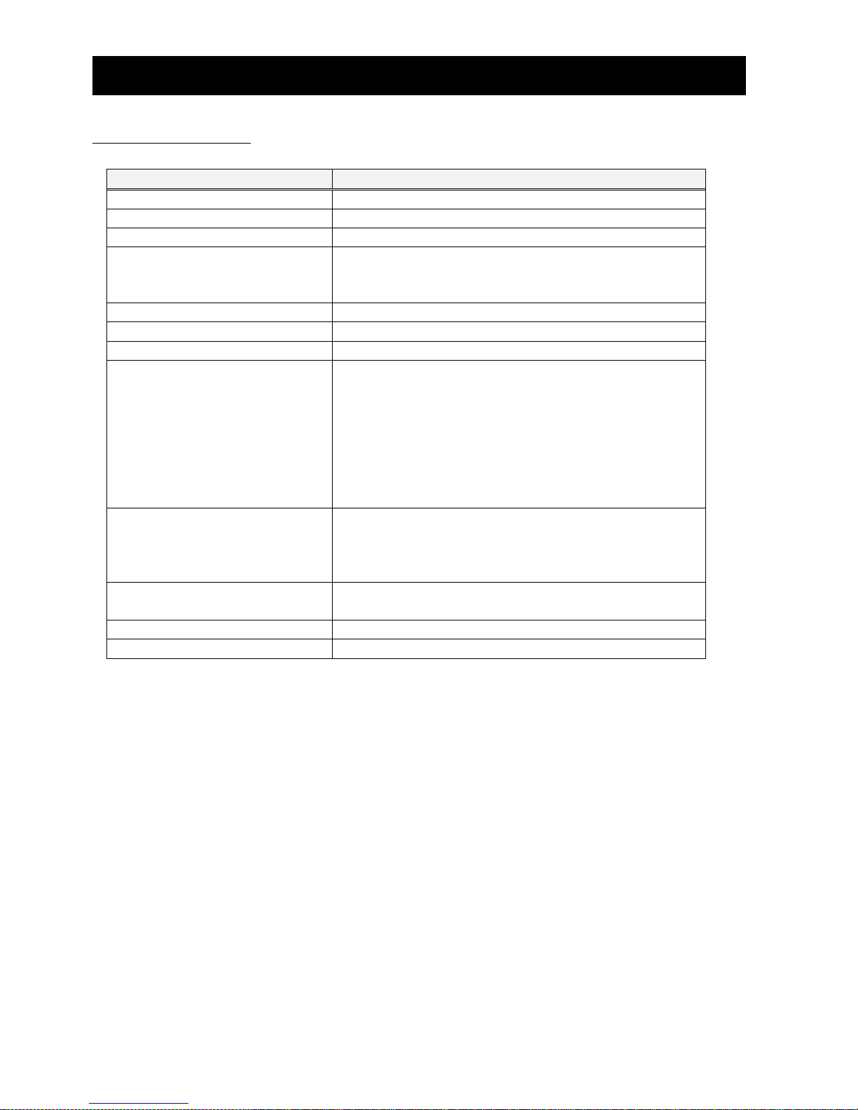
Specifications for WJ-PN are the following.
Item
Specification
Communications protocol
PROFINET IO Ver2.32
Device type
PROFINET IO Device
Conformance class
B
Protocol
DCP (Discovery and basic Configuration Protocol)
LLDP (Link Layer Discovery Protocol)
SNMP (Simple Network Management Protocol)
Netload
I
RT / IRT
only RT
Profile
PROFIdrive
LLDP
Support TLV
chassis ID
port ID
Time To Live
LLDP_PNIO_PORTSTATUS
LLDP_PNIO_CHASSIS_MAC
LLDP8023MACPHY
LLDPManagement
End TLV
SNMP
Support MIB
MIB-2
LLDP-MIB
LLDP-EXT-PNIO-MIB
LLDP-EXT-DOT3-MIB
Physical layer
Auto negotiation
(100BASE-TX (IEEE802.3) only)
port
2 ports
MAC address
3 (Host, Port 1 / 2)
Page 29
Chapter 8 PROFINET Specification
23
8.2 Device Name (NameOfStation) and IP address
You need to set device name (NameOfStation) and IP address to WJ-PN with engineering tool.
Please refer to the manual of the engineering tool for the usage.
8.3 MAC address
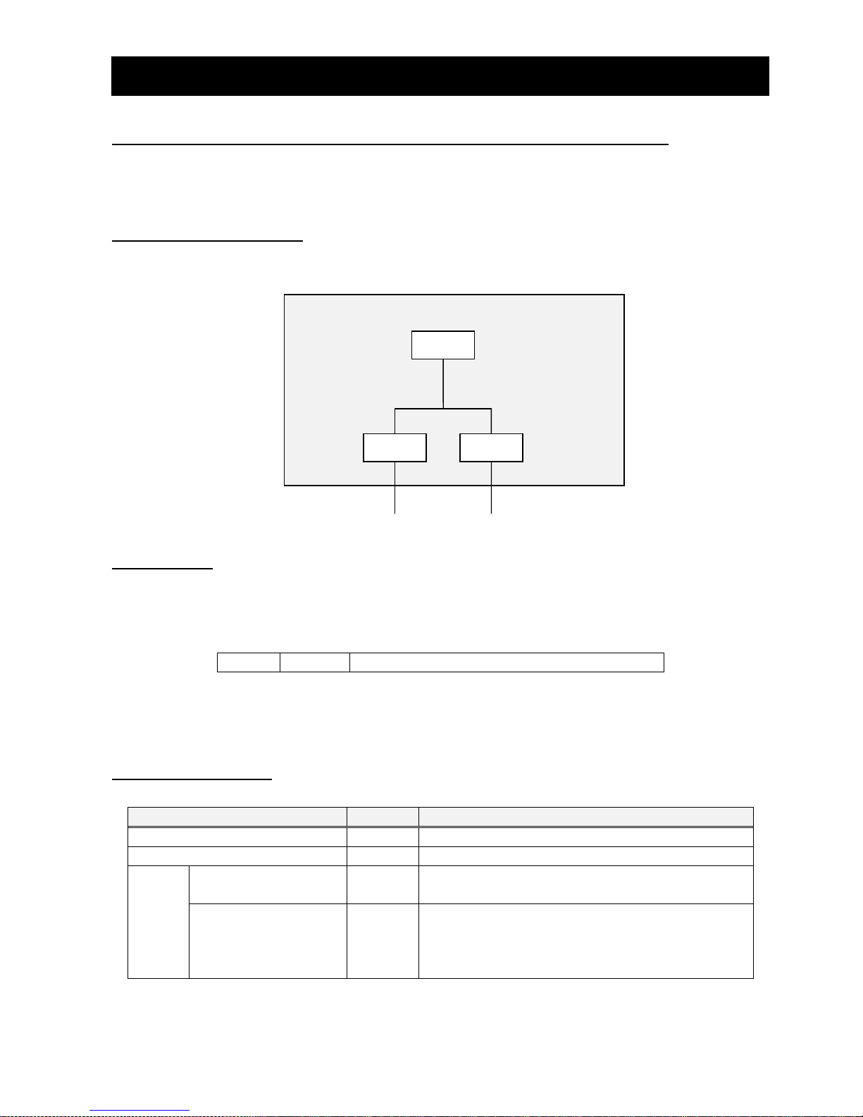
WJ-PN has 3 MAC addresses of host, port1, and port2.
Ethernet
port1
MAC address
port2
MAC address
Ethernet
Host
MAC address
MAC
MAC
MAC
8.4 LLDP
LLDP (Link Layer Discovery Protocol) is a function to transmit own device information to the
neighbor devices at a fixed interval.
LLDP packet consists of multiple TLV (type-length-value). A TLV consists of 3 fields (type, length,
and value) and expresses a kind of information. In the case of following figure, length is n.
Type
Length
Value
7 bits
9 bits
n bit
Please refer to the following subsection about the details of TLV of WJ-PN, and IEEE802.1AB-2009
about LLDP.
8.4.1 chassis ID
This data indicates the WJ-PN information.
Item
Length
Value
Type
7 bits
1
Length
9 bits
n+1
Value
chassis ID subtype
1 byte
4 : MAC address of this port
7 : Device name (NameOfStation)
chassis ID
n bytes
When the device name (NameOfStation) is set to
WJ-PN, this data is device name (NameOfStation).
When the device name (NameOfStation) isn’t set
to WJ-PN, this data is MAC address of this port.
Page 30
Chapter 8 PROFINET Specification
24
8.4.2 port ID
This data indicates the port information at which WJ-PN transmits LLDP packet.
Item
Length
Value
Type
7 bits
2
Length
9 bits
9
Value
port ID subtype
1 byte
7
port ID
8 bytes
port 1 : port-001
port 2 : port-002
8.4.3 Time To Live
This data indicates the seconds which is retention time.
Item
Length
Value
Type
7 bits
3
Length
9 bits
9
Value
Time To Live
1 byte
20
8.4.4 LLDP_PNIO_PORTSTATUS
This data is particular TLV to PROFINET, and indicates the PROFINET port information.
Item
Length
Value
Type
7 bits
0x7F
Length
9 bits
8
Value
OUI
3 bytes
0x00 0x0E 0xCF
subtype
1 byte
2
RTClass2 port status
2 bytes
0
RTClass3 port status
2 bytes
0
OUI (Organizationally Unique Identifier) is the unique identifier. OUI which is 0x00 0x0E 0xCF
indicates PROFINET.
WJ-PN doesn’t support RTClass2 and RTClass3.
8.4.5 LLDP_PNIO_CHASSIS_MAC
This data is particular TLV to PROFINET, and indicates the device information.
Item
Length
Value
Type
7 bits
0x7F
Length
9 bits
10
Value
OUI
3 bytes
0x00 0x0E 0Xcf
subtype
1 byte
5
MAC address
6 bytes
MAC address of host
Page 31
Chapter 8 PROFINET Specification
25
8.4.6 LLDP8023MACPHY
This data is particular TLV to IEEE802.3 (Ethernet), and indicates the information about Ethernet.
OUI which is 0x00 0x12 0x0F indicates IEEE802.3.
Item
Length
Value
Type
7 bits
0x7F
Length
9 bits
9
Value
OUI
3 bytes
0x00 0x12 0x0F
subtype
1 byte
1
auto negotiation
1 byte
3
Bit 0 indicates that WJ-PN supports Auto
negotiation.
Bit 1 indicates that Auto negotiation is active.
transmission speed
2 bytes
0x0400
Bit 11 indicates that WJ-PN supports
100BASE-TX.
The other bits indicate that WJ-PN doesn’t
support the other transmission speed.
actually
transmission speed
2 bytes
0x0010
This indicates that the transmission speed is
100BASE-TX Full.
8.4.7 LLDPManagement
This data indicates the management information. OID (Object Identifier) is enterprise number of PI.
Item
Length
Value
Type
7 bits
8
Length
9 bits
20
Value
Management address
length
1 byte
5 Management address
subtype
1 byte
1
Management address
4 bytes
IP address
Interface numbering
subtype
1 byte
2
Interface number
4 bytes
1
OID length
1 byte
8
OID
8 bytes
0x2B 0x06 0x01 0x04 0x01 0x81 0xC0 0x6E
This indicates that OID is ‘1.3.6.1.4.1.24686’.
8.4.8 End
This data indicates the end of LLDP packet.
Item
Length
Value
Type
7 bits
0
Length
9 bits
0
Page 32
Chapter 8 PROFINET Specification
26
8.5 SNMP
Please refer to following section about the OIDs (Object Identifier) that WJ-PN supports. The
“access” and “type” shall be as follows.
[Access]
Access
Meaning
R
Read only
W
Write only
RW
Read and write
N
Not accessible
[Type]
Data type
Expression in tables
Meaning
Integer
INT*
Singed integer.
“*” indicates bit length.
Octet string
OS[*]
Byte strings.
“*” indicates the number of characters.
No “*” means read only data.
Object identifier
OID
Object identifier
IpAddress
IpAddress
IP address.
This is Octet string has 4 characters.
Counter32
Counter32
From 0 to 4294967295.
Unsigned32
UINT32
From 0 to 4294967295.
Gauge32
Gauge32
From 0 to 4294967295.
TimeTicks
TimeTicks
From 0 to 4294967295.
This indicates the time in hundredths of a
second between two epochs.
Opaque
Opaque
Octet string
Counter64
Counter64
From 0 to 18446744073709551615.
Page 33
Chapter 8 PROFINET Specification
27
8.5.1 MIB-2
OID
Object name
Access
Type
1.3.6.1.2.1.1.1
sysDescr
R
OS
1.3.6.1.2.1.1.2
sysObjectID
R
OID
1.3.6.1.2.1.1.3
sysUpTime
R
TimeTicks
1.3.6.1.2.1.1.4
sysContact
RW
OS[255]
1.3.6.1.2.1.1.5
sysName
RW
OS[255]
1.3.6.1.2.1.1.6
sysLocation
RW
OS[255]
1.3.6.1.2.1.1.7
sysServices
R
INT
1.3.6.1.2.1.2.1
ifNumber
R
INT32
1.3.6.1.2.1.2.2
ifTable
N
1.3.6.1.2.1.2.2.1
ifEntry
N
1.3.6.1.2.1.2.2.1.1
ifIndex
R
INT32
1.3.6.1.2.1.2.2.1.2
ifDescr
R
OS
1.3.6.1.2.1.2.2.1.3
ifType
R
INT
1.3.6.1.2.1.2.2.1.4
ifMtu
R
INT32
1.3.6.1.2.1.2.2.1.5
ifSpeed
R
Gauge32
1.3.6.1.2.1.2.2.1.6
ifPhysAddress
R
OS[6]
1.3.6.1.2.1.2.2.1.7
ifAdminStatus
R
INT
1.3.6.1.2.1.2.2.1.8
ifOperStatus
R
INT
1.3.6.1.2.1.2.2.1.9
ifLastChange
R
TimeTicks
1.3.6.1.2.1.2.2.1.10
ifInOctets
R
Counter32
1.3.6.1.2.1.2.2.1.11
ifInUcastPkts
R
Counter32
1.3.6.1.2.1.2.2.1.12
ifInNUcastPkts
R
Counter32
1.3.6.1.2.1.2.2.1.13
ifInDiscards
R
Counter32
1.3.6.1.2.1.2.2.1.14
ifInErrors
R
Counter32
1.3.6.1.2.1.2.2.1.15
ifInUnknownProtos
R
Counter32
1.3.6.1.2.1.2.2.1.16
ifOutOctets
R
Counter32
1.3.6.1.2.1.2.2.1.17
ifOutUcastPkts
R
Counter32
1.3.6.1.2.1.2.2.1.18
ifOutNUcastPkts
R
Counter32
1.3.6.1.2.1.2.2.1.19
ifOutDiscards
R
Counter32
1.3.6.1.2.1.2.2.1.20
ifOutErrors
R
Counter32
1.3.6.1.2.1.2.2.1.21
ifOutQLen
R
Gauge32
1.3.6.1.2.1.2.2.1.22
ifSpecific
R
OID
8.5.2 LLDP-MIB
OID
Object name
Access
Type
1.0.8802.1.1.2
lldpMIB
N
1.0.8802.1.1.2.1
lldpObjects
N
1.0.8802.1.1.2.1.1
lldpConfiguration
N 1.0.8802.1.1.2.1.1.7
lldpConfigManAddrTable
N
1.0.8802.1.1.2.1.1.7.1
lldpConfigManAddrEntry
N
1.0.8802.1.1.2.1.1.7.1.1
lldpConfigManAddrPortsTxEnable
R
OS[1]
1.0.8802.1.1.2.1.3
lldpLocalSystemData
N
1.0.8802.1.1.2.1.3.1
lldpLocChassisIdSubtype
R
INT
Page 34
Chapter 8 PROFINET Specification
28
OID
Object name
Access
Type
1.0.8802.1.1.2.1.3.2
lldpLocChassisId
R
OS[255]
1.0.8802.1.1.2.1.3.3
lldpLocSysName
R
OS[255]
1.0.8802.1.1.2.1.3.4
lldpLocSysDesc
R
OS[255]
1.0.8802.1.1.2.1.3.5
lldpLocSysCapSupported
R
OS[1]
1.0.8802.1.1.2.1.3.6
lldpLocSysCapEnabled
R
OC[1]
1.0.8802.1.1.2.1.3.7
lldpLocPortTable
N
1.0.8802.1.1.2.1.3.7.1
lldpLocPortTableEntry
N 1.0.8802.1.1.2.1.3.7.1.1
lldpLocPortNum
N
INT32
1.0.8802.1.1.2.1.3.7.1.2
lldpLocPortIdSubtype
R
INT
1.0.8802.1.1.2.1.3.7.1.3
lldpLocPortId
R
OS[255]
1.0.8802.1.1.2.1.3.7.1.4
lldpLocPortDesc
R
OS[255]
1.0.8802.1.1.2.1.3.8
lldpLocManAddrTable
N
1.0.8802.1.1.2.1.3.8.1
lldpLocManAddrEntry
N 1.0.8802.1.1.2.1.3.8.1.1
lldpLocManAddrSubtype
N
INT
1.0.8802.1.1.2.1.3.8.1.2
lldpLocManAddr
N
OS[31]
1.0.8802.1.1.2.1.3.8.1.3
lldpLocManAddrLen
R
INT32
1.0.8802.1.1.2.1.3.8.1.4
lldpLocManAddrIfSubtype
R
INT
1.0.8802.1.1.2.1.3.8.1.5
lldpLocManAddrIfId
R
INT32
1.0.8802.1.1.2.1.3.8.1.6
lldpLocManAddrOID
R
OID
1.0.8802.1.1.2.1.4
lldpRemoteSystemsData
N
1.0.8802.1.1.2.1.4.1
lldpRemTable
N
1.0.8802.1.1.2.1.4.1.1
lldpRemEntry
N 1.0.8802.1.1.2.1.4.1.1.1
lldpRemTimeMark
N
TimeTicks
1.0.8802.1.1.2.1.4.1.1.2
lldpRemLocalPortNum
N
INT32
1.0.8802.1.1.2.1.4.1.1.3
lldpRemIndex
N
INT32
1.0.8802.1.1.2.1.4.1.1.4
lldpRemChassisIdSubtype
R
INT
1.0.8802.1.1.2.1.4.1.1.5
lldpRemChassisId
R
OS[255]
1.0.8802.1.1.2.1.4.1.1.6
lldpRemPortIdSubtype
R
INT
1.0.8802.1.1.2.1.4.1.1.7
lldpRemPortId
R
OS[255]
1.0.8802.1.1.2.1.4.1.1.8
lldpRemPortDesc
R
OS[255]
1.0.8802.1.1.2.1.4.1.1.9
lldpRemSysName
R
OS[255]
1.0.8802.1.1.2.1.4.1.1.10
lldpRemSysDesc
R
OS[255]
1.0.8802.1.1.2.1.4.1.1.11
lldpRemSysCapSupported
R
OS[1]
1.0.8802.1.1.2.1.4.1.1.12
lldpRemSysCapEnabled
R
OS[1]
1.0.8802.1.1.2.1.4.2
lldpRemManAddrTable
N
1.0.8802.1.1.2.1.4.2.1
lldpRemManAddrEntry
N
1.0.8802.1.1.2.1.4.2.1.1
lldpRemManAddrSubtype
N
INT
1.0.8802.1.1.2.1.4.2.1.2
lldpRemManAddr
N
OS[31]
1.0.8802.1.1.2.1.4.2.1.3
lldpRemManAddrIfSubtype
R
INT
1.0.8802.1.1.2.1.4.2.1.4
lldpRemManAddrIfId
R
INT32
1.0.8802.1.1.2.1.4.2.1.5
lldpRemManAddrOID
R
OID
8.5.3 LLDP-EXT-PNIO-MIB
OID
Object name
Access
Type
1.0.8802.1.1.2.1.5
lldpExtensions
N
Page 35
Chapter 8 PROFINET Specification
29
OID
Object name
Access
Type
1.0.8802.1.1.2.1.5.3791
lldpXPnoMIB
N
1.0.8802.1.1.2.1.5.3791.1
lldpXPnoObjects
N 1.0.8802.1.1.2.1.5.3791.1.2
lldpXPnoLocalData
1.0.8802.1.1.2.1.5.3791.1.2.1
lldpXPnoLocTable
N
1.0.8802.1.1.2.1.5.3791.1.2.1.1
lldpXPnoLocEntry
N 1.0.8802.1.1.2.1.5.3791.1.2.1.1.1
lldpXPnoLocLPDValue
R
UINT32
1.0.8802.1.1.2.1.5.3791.1.2.1.1.2
lldpXPnoLocPortTxDValue
R
UINT32
1.0.8802.1.1.2.1.5.3791.1.2.1.1.3
lldpXPnoLocPortRxDValue
R
UINT32
1.0.8802.1.1.2.1.5.3791.1.2.1.1.6
lldpXPnoLocPortNoS
R
OS[255]
1.0.8802.1.1.2.1.5.3791.1.3
lldpXPnoRemoteData
1.0.8802.1.1.2.1.5.3791.1.3.1
lldpXPnoRemTable
N 1.0.8802.1.1.2.1.5.3791.1.3.1.1
lldpXPnoRemEntry
N
1.0.8802.1.1.2.1.5.3791.1.3.1.1.1
lldpXPnoRemLPDValue
R
UINT32
1.0.8802.1.1.2.1.5.3791.1.3.1.1.2
lldpXPnoRemPortTxDValue
R
UINT32
1.0.8802.1.1.2.1.5.3791.1.3.1.1.3
lldpXPnoRemPortRxDValue
R
UINT32
1.0.8802.1.1.2.1.5.3791.1.3.1.1.6
lldpXPnoRemPortNoS
R
OS[255]
8.5.4 LLDP-EXT-DOT3-MIB
OID
Object name
Access
Type
1.0.8802.1.1.2.1.5.4623
lldpXdot3MIB
N 1.0.8802.1.1.2.1.5.4623.1
lldpXdot3Objects
N
1.0.8802.1.1.2.1.5.4623.1.2
lldpXdot3LocalData
1.0.8802.1.1.2.1.5.4623.1.2.1
lldpXdot3LocPortTable
N 1.0.8802.1.1.2.1.5.4623.1.2.1.1
lldpXdot3LocPortEntry
N
1.0.8802.1.1.2.1.5.4623.1.2.1.1.1
lldpXdot3LocPortAutoNegSupported
R
INT
1.0.8802.1.1.2.1.5.4623.1.2.1.1.2
lldpXdot3LocPortAutoNegEnabled
R
INT
1.0.8802.1.1.2.1.5.4623.1.2.1.1.3
lldpXdot3LocPortAutoNegAdvertisedCap
R
OS[2]
1.0.8802.1.1.2.1.5.4623.1.2.1.1.4
lldpXdot3LocPortOperMauType
R
INT32
1.0.8802.1.1.2.1.5.4623.1.3
lldpXdot3RemoteData
N 1.0.8802.1.1.2.1.5.4623.1.3.1
lldpXdot3RemPortTable
N
1.0.8802.1.1.2.1.5.4623.1.3.1.1
lldpXdot3RemPortEntry
N
1.0.8802.1.1.2.1.5.4623.1.3.1.1.1
lldpXdot3RemPortAutoNegSupported
R
INT
1.0.8802.1.1.2.1.5.4623.1.3.1.1.2
lldpXdot3RemPortAutoNegEnabled
R
INT
1.0.8802.1.1.2.1.5.4623.1.3.1.1.3
lldpXdot3RemPortAutoNegAdvertisedCap
R
OS[2]
1.0.8802.1.1.2.1.5.4623.1.3.1.1.4
lldpXdot3RemPortOperMauType
R
INT32
Page 36
Chapter 8 PROFINET Specification
30
8.6 PROFIdrive
Specifications for PROFIdrive of WJ-PN are the following.
Item
Specification
Version
4.2
Application class
AC1 (Standard Drive)
Telegram
Standard telegram 1
WJ-PN telegram 103 (same as PPO3 of PROFIdrive version 2)
WJ-PN telegram 104 (same as PPO4 of PROFIdrive version 2)
WJ-PN telegram 105 (like PPO5 of PROFIdrive version 2)
Configuring of telegram
From P160 to P179 of WJ200 / WL200 parameters
Operating mode
Speed control mode
Jogging
Only jogging 1 is supported.
The size of send and receive data of each telegram are the following.
WJ-PN telegrams are the device specific telegrams and compatible with PPOs of PROFIdrive
version 2. However, WJ-PN telegram doesn’t have PKW (parameter area) and has only PZD (process
data area).
Telegram
Setpoint
(from PROFINET IO
controller to WJ-PN)
Actual value
(from WJ-PN to
PROFINET IO
controller)
Standard telegram 1
2 word
2 word
WJ-PN telegram 103
(same as PPO3 of PROFIdrive version 2)
2 word
2 word
WJ-PN telegram 104
(same as PPO4 of PROFIdrive version 2)
6 word
6 word
WJ-PN telegram 105
(like PPO5 of PROFIdrive version 2)
10 word
10 word
Please refer to “8.12 Telegram” for details of each telegram.
Page 37
Chapter 8 PROFINET Specification
31
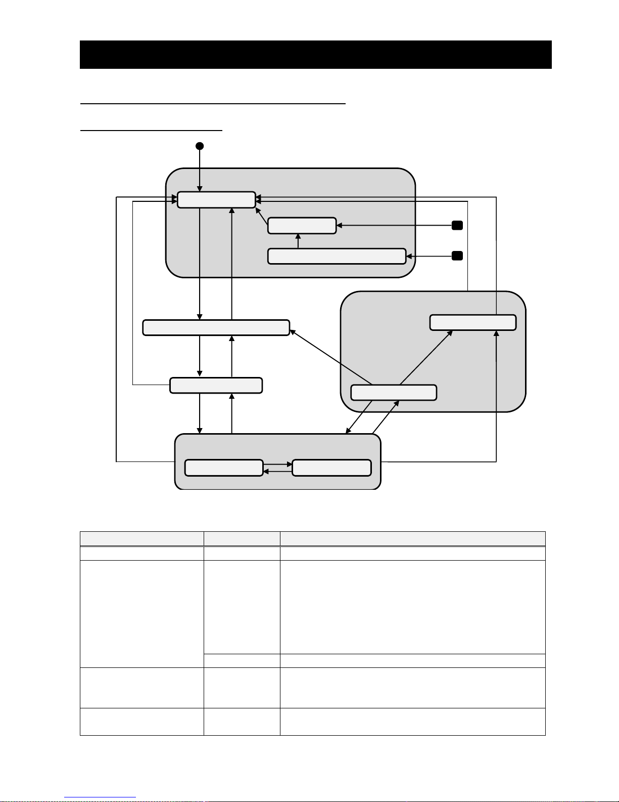
8.7 State machine on PROFIdrive
8.7.1 State diagram
S1 : Switching On Inhibited
S2 : Ready For Switching On
S3 : Switched On
S4 : Operation
S5 : Switching Off
S1-1 : Normal
S1-2 : Fault
S1-3 : Fault reaction active
S4-1 : Normal
S4-2 : Jogging
S51 : ramp stop
S52 : quick stop
(0_1)
(1-1_2)
(2_1)
(2_3)
(3_2)
(3_4)
(4_3)
(3_1)
(4_1)
(51_4)
(4_51)
(4_52)
(51_2)
(5_1)
(52_1)
(1-3_1-2)
(51_52)
(4-1_4-2)
(4-2_4-1)
(1-2_1-1)
(0_1-3)
(0_1-2)
Start
Note : The black rounded rectangles means every states.
Each transition is the following. Upper transition is given priority.
Transition source
Transition
Condition
From initial state
(0_1)
Power on, or reset.
In case of error.
(0_1-3)
When WJ200 / WL200 is on the operation and either of
the following conditions are satisfied.
- The communication error is occurred between
WJ-PN and WJ200 / WL200.
- The communication timeout error that it has been
the time of P044 since previous communication
occurs on PROFINET and P045 = 1.
(0_1-2)
When except the above error occurs.
From S1-1
(1-1_2)
When all of the following conditions of STW1 are
satisfied.
Bit0 = OFF, Bit1 = ON, Bit2 = ON
From S1-2
(1-2_1-1)
When STW1 Bit7 becomes from OFF to ON and keeps
ON for at least 20ms.
Page 38
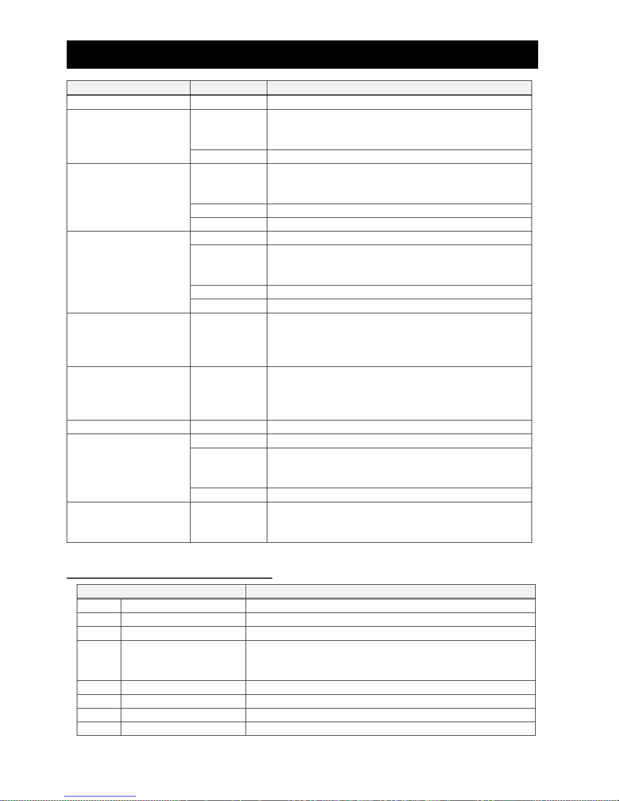
Chapter 8 PROFINET Specification
32
Transition source
Transition
Condition
From S1-3
(1-3_1-2)
The output frequency of WJ200 / WL200 is 0 [Hz].
From S2
(2_1)
When either of the following conditions of STW1 is
satisfied.
Bit1 = OFF, Bit2 = OFF
(2_3)
STW1 Bit0 = ON
From S3
(3_1)
When either of the following conditions of STW1 is
satisfied.
Bit1 = OFF, Bit2 = OFF
(3_2)
STW1 Bit0 = OFF
(3_4)
STW1 Bit3 = ON
From S4
(4_1)
STW1 Bit1 = OFF
(4_52)
When either of the following conditions are satisfied.
- STW1 Bit 2 = OFF.
- STW1 Bit 0 = ON and Bit 4 = OFF.
(4_51)
STW1 Bit0 = OFF
(4_3)
STW1 Bit3 = OFF
From S4-1
(4-1_4-2)
When all of the following conditions are satisfied.
- The output frequency of WJ200 / WL200 is 0 [Hz].
- All of STW1 Bit 4- 6 are OFF.
- STW1 Bit 8 is ON
From S4-2
(4-2_4-1)
When all of the following conditions are satisfied.
- The output frequency of WJ200 / WL200 is 0 [Hz].
- Either of STW1 Bit 4- 6 is ON.
- STW1 Bit 8 is OFF
From S5
(5_1)
STW1 Bit1 = OFF
From S51
(51_52)
STW1 Bit2 = OFF
(51_2)
When either of the following conditions are satisfied.
- The output frequency of WJ200 / WL200 is 0 [Hz].
- STW1 Bit 3 = OFF.
(51_4)
STW1 Bit0 = ON
From S52
(52_1)
When either of the following conditions are satisfied.
- The output frequency of WJ200 / WL200 is 0 [Hz].
- STW1 Bit 3 = OFF.
8.7.2 Description each state
State
Description
S1
Switching On Inhibited
Inverter is stopping.
S1-1
Normal
No Error occurs in inverter.
S1-2
Fault
An error occurs and the error is not cleared.
S1-3
Fault reaction active
WJ-PN detects an error, and inverter is during deceleration.
When inverter stops, WJ-PN makes inverter trip and changes
the state to S1-2.
S2
Ready For Switching On
Inverter is stopping.
S3
Switched On
Inverter is stopping.
S4
Operation
Inverter can be operated.
S4-1
Normal
Inverter is running normally.
Page 39
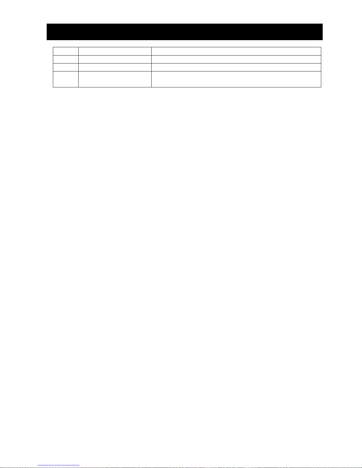
Chapter 8 PROFINET Specification
33
S4-2
Jogging
Inverter is running by jogging.
S5
Switching Off
Inverter is decelerating.
S51
ramp stop
Inverter is decelerating by ramp stop.
S52
quick stop
Inverter is decelerating by quick stop (2ch function of
WJ200 / WL200).
The state S*-* aren’t defined at the figure of General State Diagram in the PROFIdrive specification.
Page 40
Chapter 8 PROFINET Specification
34
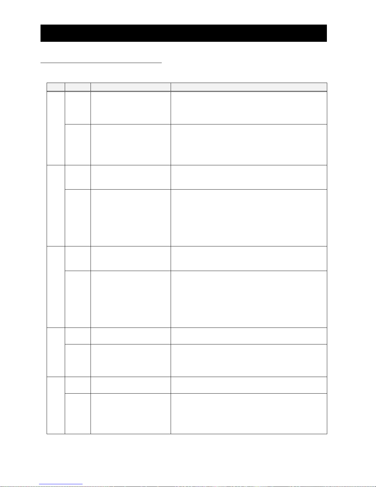
8.8 STW1 (Control word)
The size of STW1 is 16 bits.
The specification of each bit is the following.
Bit
Value
Significance
Description
0 1 ON
When the state is in “Ready For Switching On”, the
state is changed to “Switched On”.
When the state is in “ramp stop”, the state is
changed to “Operation”.
0 OFF
(OFF 1)
When the state is in “Switched On”, the state is
changed to “Ready For Switching On”.
When the state is in “Operation”, the state is
changed to “ramp stop” and inverter decelerates
by ramp stop.
1 1 No Coast Stop
(no OFF 2)
When the state is in “Switching On Inhibited” and
STW1 bit2 is ON, the state is changed to “Ready For
Switching On”.
0 Coast Stop
(OFF 2)
When the state is in “Ready For Switching On” or
“Switched On”, the state is changed to “Switching
On Inhibited”.
When the state is in “Operation” or “Switching Off
(ramp stop or quick stop)”, the state is changed to
“Switching On Inhibited” and inverter stops by
coast stop.
2 1 No Quick Stop
(no OFF 3)
When the state is in “Switching On Inhibited” and
STW1 bit1 is ON, the state is changed to “Ready For
Switching On”.
0 Quick Stop
(OFF 3)
When the state is in “Ready For Switching On” or
“Switched On”, the state is changed to “Switching
On Inhibited”.
When the state is in “Operation” or “ramp stop”,
the state is changed to “quick stop” and inverter
decelerates by 2ch function of WJ200 / WL200. If
C005 isn’t 2ch, inverter decelerates by ramp stop.
3 1 Enable Operation
When the state is in “Switched On”, the state is
changed to “Operation”.
0 Disable Operation
When the state is in “ramp stop”, the state is
changed to “Ready For Switching On”.
When the state is in “quick stop”, the state is
changed to “Switching On Inhibited”.
4 1 Enable Ramp Generator
The output frequency is set Speed Setpoint A
(NSOLL_A) and inverter accelerates.
0 Reset Ramp Generator
The output frequency is set 0 and inverter runs by 0
[Hz].
When inverter is running and both this bit and bit 0
are changed from 1 to 0, inverter decelerates and
stops by 2CH function of WJ200 / WL200.
Page 41
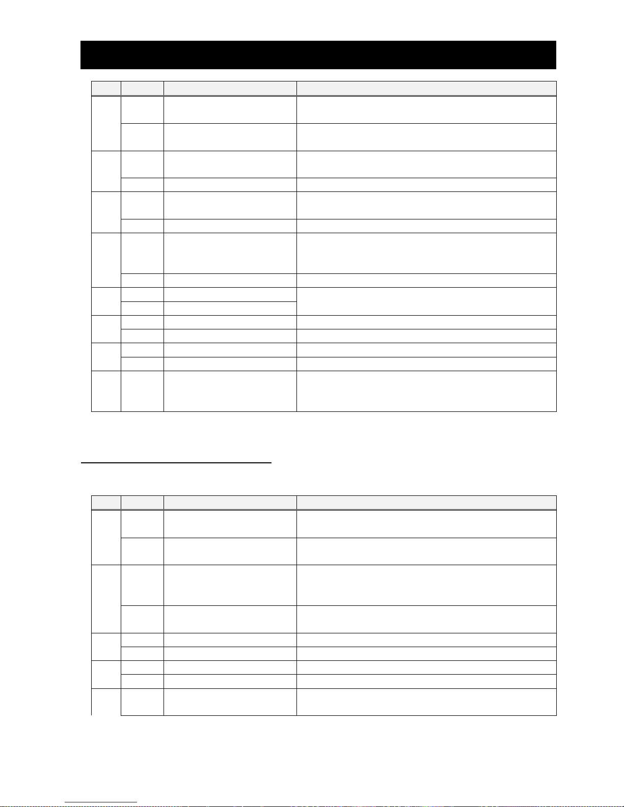
Chapter 8 PROFINET Specification
35
Bit
Value
Significance
Description
5 1 Unfrreze Ramp Generator
The current output frequency isn’t held. Inverter
runs by the output frequency.
0 Freeze Ramp Generator
When C006 is HLD, the current output frequency is
held.
6 1 Enable Setpoint
The output frequency is set Speed Setpoint A
(NSOLL_A).
0 Disable Setpoint
The output frequency is set 0.
7 1 Fault Acknowledge
(0 -> 1)
When this bit is changed from 0 to 1, errors are
cleared.
0 No significance
Do nothing.
8 1 Jog 1 ON
When the state is “Operation”, the output
frequency is 0 and bit4 - 6 are 0, inverter runs by
jogging.
0 Jog 1 OFF
When inverter runs by jogging, Inverter stops.
9 1 Jog 2 ON
Not supported
0 Jog 2 OFF
10 1 Control By PLC
Inverter can be controled by PLC.
0 No Control By PLC
Inverter can’t be controled by PLC.
11 1 Reverse
Inverter runs in reverse direction.
0 Forward
Inverter runs in forward direction.
12
15
Unsupported
Bit 11 is device specific.
8.9 ZSW1 (Status word)
The size of ZSW1 is 16 bits.
The specification of each bit is the following.
Bit
Value
Significance
Description
0 1 Ready To Switch On
When the state isn’t “Switching On Inhibited”,
this bit is ON.
0 Not Ready To Switch On
When the state is “Switching On Inhibited”, this bit
is OFF.
1 1 Ready To Operate
When the state is “Switched On”, “Operation” or
“Switching Off (ramp stop or quick stop)”, this bit is
ON.
0 Not Ready To Operate
When the state is “Switching On Inhibited” or
“Ready For Switching On”, this bit is OFF.
2 1 Operation Enabled
When the state is “Operation”, this bit is ON.
0 Operation Disabled
When the state isn’t “Operation”, this bit is OFF.
3 1 Fault Present
When error occurs in inverter or WJ-PN, this bit is ON.
0 No Fault
No error occurs in inverter or WJ-PN.
4 1 Coast Stop Not Activated
(No OFF 2)
When STW1 bit1 is ON, this bit is ON.
Page 42
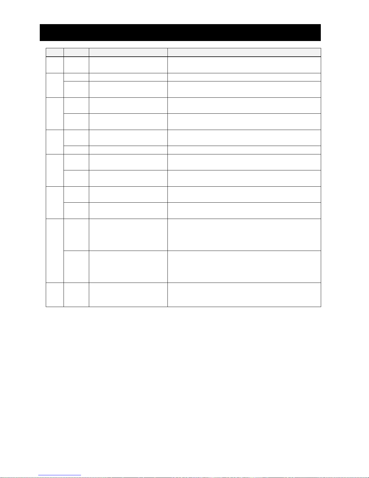
Chapter 8 PROFINET Specification
36
Bit
Value
Significance
Description
0 Coast Stop Activated
(OFF 2)
When STW1 bit1 is OFF, this bit is OFF.
5 1 Quick Stop Not Activated
When STW2 bit1 is ON, this bit is ON.
0 Quick Stop Activated
(OFF 3)
When STW2 bit1 is OFF, this bit is OFF.
6 1 Switching On Inhibited
When the state is “Switching On Inhibited”, this bit
is ON.
0 Switching On Not Inhibit
When the state isn’t “Switching On Inhibited”,
this bit is OFF.
7 1 Warning Present
When warning occurs in inverter or WJ-PN, this bit is
ON.
0 No Warning
No warning occurs in inverter or WJ-PN.
8 1 Speed Error Within
Tolerance Range
When the output frequency reaches the set
frequency, this bit is ON.
0 Speed Error Out Of
Tolerance Range
When the output frequency doesn’t reach the set
frequency, this bit is OFF.
9 1 Control Requested
WJ-PN can accept data that is communicated by
PROFINET.
0 No Control Requested
WJ-PN can’t accept data that is communicated by
PROFINET.
10 1 f Or n Reached Or
Exceeded
When the output frequency reaches or exceeds the
set frequency, this bit is ON.
This bit is same as FA2 of WJ200 / WL200. You need
to set C042 and C043.
0 f Or n Not Reached
When the output frequency doesn’t reach and
exceed the set frequency, this bit is OFF.
This bit is same as FA2 of WJ200 / WL200. You need
to set C042 and C043.
11
15
Reserved
Page 43
Chapter 8 PROFINET Specification
37
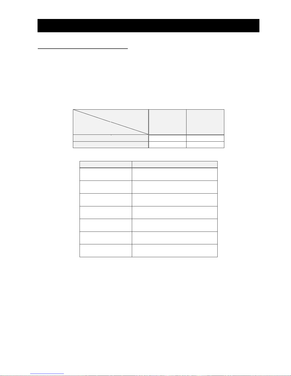
8.10 NSOLL_A / NIST_A
NSOLL_A is Speed setpoint A, means the setting of output frequency. Inverter runs this setting at not
jogging but normal operation. When inverter runs at jogging, inver ter runs not NSOLL_A but A038 of
WJ200 / WL200 parameter.
NIST_A is Speed actual value A, means the actual output frequency. This value means the actual
output frequency at both normal and jogging operations.
The size of these is signed 16 bits data. The sign means direction of rotation. The positive value
means forward, the negative value means reverse. However, the actual direction of rotation depends
on both the sign of NSOLL_A and STW1 bit11.
STW1
bit11
ON
OFF
NSOLL_A
Positive
Reverse
Forward
Negative
Forward
Reverse
The data type of these is N2. The value of N2 means the following.
Value
Significance
-32768
(0x8000)
-200 %
-32767 ~ -1
(0x8001 ~ 0xFFFF)
-199.993896484375 % ~
-0.0061 %
-16384
(0xC000)
-100 %
0
(0x0)
0 %
16384
(0x4000)
100 %
1 ~ 32766
(0x1 ~ 0x7FFE)
0.0061 % ~ 199.98779296875 %
32767
(0x7FFF)
199.993896484375 %
The base frequency of these is set A004 of WJ200 / WL200 parameter.
[Example]
When A004 = 60.0 [Hz] and NSOLL_A = 8192 (0x2000 : 50%), inverter runs 30.0 [Hz].
When the absolute value of NSOLL_A is over 100%, inverter runs 100%.
NIST_A always depends on A004 even if inverter runs at jogging operation. Therefore, when the
output frequency reaches the jogging frequency (A038), NIST_A doesn’t equal NSOLL_A. However,
STW1 Bit8 becomes ON.
[Example]
When A004 = 60.0 [Hz], A038 = 6.00 [Hz] and NSOLL_A = 16384 (0x4000 : 100%), inverter runs
6.0 [Hz] By jogging and NIST_A becomes 1638 (0x666 : 10%).
Page 44
Chapter 8 PROFINET Specification
38
8.11 Telegram
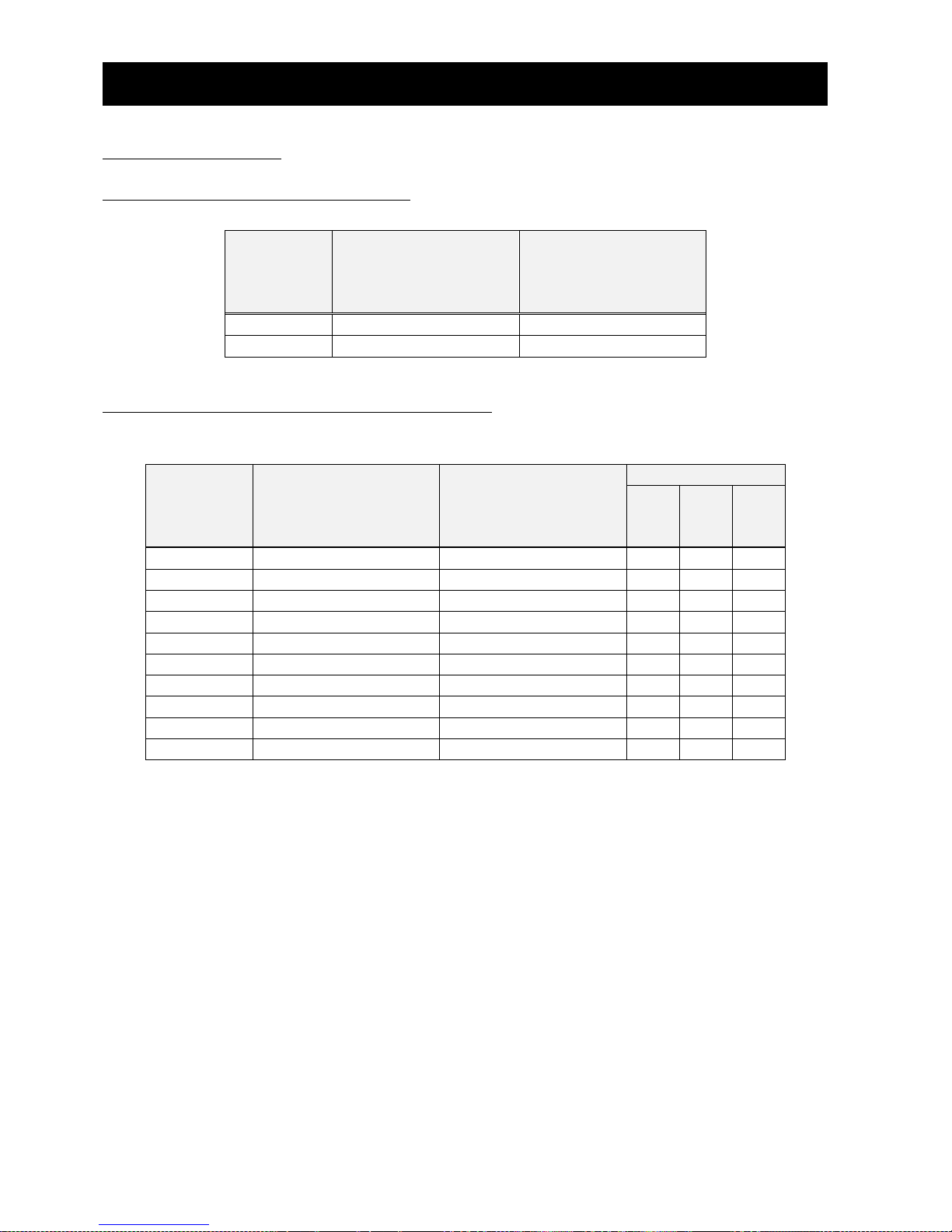
8.11.1 Standard telegram 1
Setpoint and actual value of Standard telegram 1 are the Following.
I/O Data No
Setpoint
(from PROFINET IO
controller to WJ-PN)
Actual value
(from WJ-PN to
PROFINET IO
controller)
1
STW1
ZSW1
2
NSOLL_A
NIST_A
8.11.2 WJ-PN telegram 103 to 105
Setpoint and Actual value of WJ-PN telegram 103 - 105 are the following. Send and receive data are
the data that you set P160 - 179.
I/O Data No
Setpoint
(from PROFINET IO
controller to WJ-PN)
Actual value
(from WJ-PN to
PROFINET IO
controller)
WJ-PN telegram
103
104
105
1
P160
P170
✔ ✔ ✔
2
P161
P171
✔ ✔ ✔
3
P162
P172
✔
✔
4
P163
P173
✔
✔
5
P164
P174
✔
✔
6
P165
P175
✔
✔
7
P166
P176 ✔ 8
P167
P177
✔
9
P168
P178
✔
10
P169
P179
✔
You need to set P160 - P179 to 0 or Modbus register No. of WJ200 / WL200. If you don’t use
P162 - P169 and P172 - P179, you need to set these to 0.
When you set P160 to 0, setpoint data is STW1.
When you set P161 to 0, setpoint data is NSOLL_A.
When you set P170 to 0, setpoint data is ZSW1.
When you set P171 to 0, setpoint data is NIST_A.
When you want to set 32bit length data to P160 - P179, you need to set consecutively. If you don’t
set consecutively, PNU 954 bit 4 becomes ON.
The byte order of 32bit length data depends on the setting of P160 - P179. For example, the
Modbus register No. 0x1001 is the high byte and 0x1002 is the low byte. W hen you want to set d001
to P171 and P172, you need to set either the followings.
- P171 = 0x1001, P172 = 0x1002
In this case, the high byte is sent first.
- P171 = 0x1002, P172 = 0x1001
In this case, the low byte is sent first.
Page 45

Chapter 8 PROFINET Specification
39
When you set P160 - P161 to the value that are non-existent Modbus register No. and P162 - P169
to 0 or the value that are non-existent Modbus register No., WJ-PN receives data from PROFINET IO
controller, but WJ-PN doesn’t set to WJ200 / WL200. When you set P160 - P169 non-existent
Modbus register No., PNU 954 bit 3 becomes ON.
When you set P170 - P171 to the value that are non-existent Modbus register No. and P172 - P179
to 0 or the value that are non-existent Modbus register No., WJ-PN doesn’t read data from WJ200 /
WL200 and always sends 0 to PROFINET IO controller. When you set P170 - P179 non-existent
Modbus register No., PNU 954 bit 3 becomes ON.
Hints
Please don’t assign setpoint to F001 (Modbus register No. 0x0001, 0x0002). If you want to
assign setpoint to the output frequency, you can assign it a way either of the followings.
(1) You set P161 to 0 (NSOLL_A) (The unit is % of A004)
(2) You set P160 - P169 to 0x1F14 of Modbus register No. (The unit is 0.01[Hz])
If you set P160 - P169 to F001 (Modbus register No. 0x0001, 0x0002), WJ-PN detects the warning
that PNU954 bit5 is ON and F001 of WJ200 / WL200 isn’t refreshed by the communication data.
If you set P160 - P169 to the output frequency by both above (1) and (2), WJ-PN detects the
warning that PNU954 bit6 is ON and F001 of WJ200 / WL200 isn’t reflected by the
communication data.
Page 46

Chapter 8 PROFINET Specification
40
8.12 Parameter access
You can access the parameter by Record Data CR. When you access the parameter, you need to set
0xB02E to index.
8.12.1 write data record and read data record
First you need to send a request of parameter read or write to WJ-PN by write data record (e.g.
WRREC) from PROFINET IO controller or supervisor.
Next you need to send a request to read the response to WJ-PN by read data record (e.g. RDREC)
from PROFINET IO controller or supervisor. If there is an error, the reply to a Read or Write service is
an error response.
Please refer to the PROFIdrive specification or a manual of PROFINET IO controller or supervisor
that you use.
Page 47
Chapter 8 PROFINET Specification
41
8.12.2 Parameter access on PROFIdrive
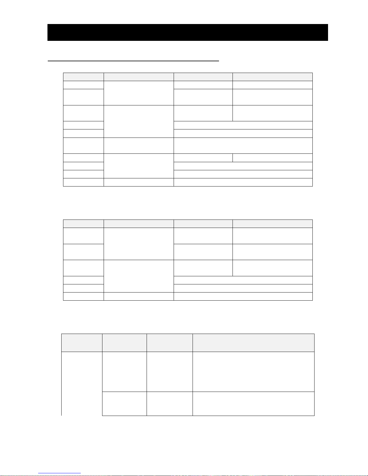
The request data frame to parameter access on PROFIdrive is the following.
Word offset
Block
Byte n
Byte n+1
0
Request header
Request reference
Request ID
1 Axis-No. / DO-ID
The number of parameters
= i
2 1st Parameter address
Attribute
The number of elements
3 PNU
4 Subindex
3i + 1
ith Parameter address
...
3i + 2
1st Parameter value
Format
The number of values
3i + 3
Value
...
ith Parameter value
...
The Parameter values need to be set only for request “Change parameter”. These don’t need to
be set for request “Request parameter”.
The response data frame to parameter access on PROFIdrive is the following.
Word offset
Block
Byte n
Byte n+1
0
Response header
Request reference
= (*)
Request ID
1 Axis-No. / DO-ID
= (*)
The number of parameters
= i
2 1st Parameter value
Format
The number of values
3 Value or error code
... ith Parameter value
...
(*)These are same as the request.
The Parameter values exist only for request “Request parameter”.
The descriptions of data are the following.
Block
Field
Data type
Description
Request
Header
Request
Reference
Unsigned8
The message ID.
Unique ID of the request / response pair
for the PROFINET IO controller.
Reserved : 0x00
ID : 0x01 - 0xFF
Request ID
Unsigned8
The type of request data.
Request parameter : 0x01
Change parameter : 0x02
Page 48
Chapter 8 PROFINET Specification
42
Block
Field
Data type
Description
Response ID
Unsigned8
The type of response data.
Request parameter (+) : 0x01
Request parameter (-) : 0x81
Change parameter (+) : 0x02
Change parameter (-) : 0x82
Unsupported service : 0x80
Axis-No. /
DO-ID
Unsigned8
Axis-No. / DO-ID that you access.
You need to set 0x00 or 0x01 in WJ-PN.
No. of
Parameters
Unsigned8
The number of parameters.
You can set from 1 to 39 in PROFINET.
Parameter
Address
Attribute
Unsigned8
The type of parameter that you access.
Value : 0x10
Description : 0x20
Text : 0x30
Number of
Elements
Unsigned8
When the parameter that you access is
Array or String, this parameter means the
number of elements.
You can set from 1 to 234.
When the parameter that you access is
the other, you need to set 0.
Parameter
Number
Unsigned16
Parameter number
Reserved : 0x0000
Parameter number : 0x0001 - 0xFFFF
Subindex
Unsigned16
The subindex of parameter
: 0x0000 - 0xFFFE
Parameter
Value
Format
Unsigned8
The data type of values.
Unsigned16 : 0x06
Unsigned32 : 0x07
Octet string : 0x0A
V2 (*) : 0x73
Zero : 0x40
(The response value doesn’t exist.)
Byte : 0x41
Word : 0x42
Double word : 0x43
Error : 0x44
Number of
Values
Unsigned8
The number of values.
This value is from 0 to 234.
Values
Depend on
data
The value that you read or change.
Error value 1
Unsigned16
Error code : 0x0000 - 0x00FF
(The lower byte is the error code.)
Error value 2
Unsigned16
It depends on an error value 1 whether
this data exist.
This value shows the subindex of the first
array element where the error occurs.
Page 49
Chapter 8 PROFINET Specification
43
(*) V2 is boolean variables are combined in two octets. Refer to the specification of PROFIdrive f or
detail.
The error codes are the following.
Error No.
= Error
value1
Meaning
Used at
Additional info
= Error value 2
0x00
Impermissible
parameter number
Access to unavailable parameter
0
0x01
Parameter value cannot
be changed
Change access to a parameter value
that cannot be changed
Subindex
0x02
Low or high limit
exceeded
Change access with value outside the
value limits
Subindex
0x03
Faulty subindex
Access to unavailable subindex of array
or string parameter. Shall not be used
for single parameters
Subindex
0x04
No array
Access with subindex to non-indexed
Parameter
0
0x05
Incorrect data type
Change access with value that does not
match the data type of the parameter
0
0x06
Setting not permitted
(may only be reset)
Change access with value unequal to 0
where this is not permitted
Subindex
0x07
Description element
cannot be Changed
Change access to a description element
that cannot be changed
Subindex
0x09
No description data
available
Access to unavailable description
(parameter value is available)
0
0x0B
No operation priority
Change access without rights to change
Parameters
0
0x0F
No text array available
Access to text array that is not available
(parameter value is available)
0
0x11
Request cannot be
executed because of
operating state
Access is temporarily not possible for
reasons that are not specified in detail.
When the parameter of WJ200 / WL200
is accessed, please check whether the
inverter can accept change access.
0
0x14
Value impermissible
Change access with a value that is
within the value limits, but is not
permissible for other long-term reasons
(parameter with defined single values)
Subindex
0x15
Response too long
The length of the current response
exceeds the maximum transmittable
length of the response transport block.
In case of a multi parameter request,
the response block was shortened by
omitting of parameter requests.
0
Page 50
Chapter 8 PROFINET Specification
44
Error No.
= Error
value1
Meaning
Used at
Additional info
= Error value 2
0x16
Parameter address
impermissible
Illegal value (reserved) or value which is
not supported for the attribute, illegal
or not supported number of elements,
illegal parameter number or illegal
subindex or a combination
0
0x17
Illegal format
Write request: Illegal format or format of
the parameter data which is not
supported
0
0x18
Number of values are
not consistent
Write request: Number of the values of
the parameter data do not match the
number of elements in the parameter
address
0
0x19
Axis/DO nonexistent
Access to an Axis/DO which does not
exist
0
0x20
Parameter text element
cannot be Changed
Change access to a parameter text
element that cannot be changed
Subindex
0x21
Service not supported
Illegal or unknown Request ID
(Response ID = 0x80)
-
0x22
Too much parameter
requests
Multi parameter request: The response
block does not contain all parameter
responses because of maximum number
of supported parameter requests per
multi parameter request was exceeded.
-
0x23
Multi parameter access
not Supported
Device parameter manager does not
support multi parameter requests.
Request is discarded.
-
0x65
0x67
Error of access to
WJ200 / WL200
(Manufacturer-specific)
It is an error of access to WJ200 /
WL200.
You access while WJ200 / WL200 is
initializing or changing the mode.
If WJ-PN returns these values while
WJ200 / WL200 isn’t initializing or
changing the mode, please contact the
nearest business contact.
-
0x66
The accessed
parameter doesn’t
exist at WL200.
(Manufacturer-specific)
You access the parameter that doesn’t
exist at WL200.
-
You can access multi parameters at a request message. However, when an error occurs, there are
cases that the process is stopped and returns the response. This depends on kind of errors. You need
to resolve/investigate what process has been done by checking the returned message, because WJ-PN
will stop the internal transaction immediately and return the message when the requested
command/address was wrong.
For example, when you set the wrong data type like the following request, the process is stopped
Page 51

Chapter 8 PROFINET Specification
45
and returns the response. The following values are hexadecimal.
[The request] (*) The underline part is the wrong data.
01 02 01 03 10 01 03 FA 00 29 10 01 07 E2 00 74 10 01 07 E2 00 76 06 01 02 58 06 01 00 00
00 00 07 01 00 00 00 00
[The response] (*) The underline parts show error.
01 82 01 02 40 00 44 01 00 05
Page 52
Chapter 8 PROFINET Specification
46
8.13 PNU (parameter number)
The parameter number is assigned to each parameter. The number range of the parameters is
specified for 0 - 65535. The details are the following.
PNU
Area
Description
0 - 899
Device specific
Unused
900 - 999
For PROFIdrive
Parameters for PROFIdrive
1000 - 59999
Device specific
(Inverter parameter area)
These are parameters to access the
parameters of WJ200 / WL200 in WJ-PN.
60000 - 60999
Reserved for PROFIdrive
Unused
61000 - 63999
Reserved for PROFIdrive
(PROFINET I/O)
Parameters for PROFINET
64000 - 65535
Reserved for PROFIdrive
Unused
8.13.1 Data types
The data types shown in the following table are used in this profile.
Data types
Code
Size
Range
Unsigned16
UINT
2 bytes
0 to 65,535
Unsigned32
UDINT
4 bytes
0 to 4,294,967,295
V2
V2
2 bytes
0x0000 to 0xFFFF
Octet string
STR
- - Array
ARRAY
-
-
8.13.2 Access
The access methods shown in the following table are used in this profile. It indicates whether the
object is read or write only, or read and write.
Access
Description
R
Read only.
W
Write only.
RW
Read and write.
Page 53
Chapter 8 PROFINET Specification
47
8.13.3 PROFIdrive area
● 915
Sub-Index
Item
Description
Name
Selection switch for DO IO Data in the setpoint telegram
Data type
ARRAY of UINT
Access
R
Default setting
0
Detail
This area displays P160 - P169 of WJ200 / WL200.
0x00
Detail
0x0000 : STW1
The others : Modbus register No. of WJ200 / WL200
0x01
Detail
0x0000 : NSOLL_A
The others : Modbus register No. of WJ200 / WL200
0x02
0x09
Detail
0x0000 : Unused
The others : Modbus register No. of WJ200 / WL200
● 916
Sub-Index
Item
Description
Name
Selection switch for DO IO Data in the actual value telegram
Data type
ARRAY of UINT
Access
R
Default setting
0
Detail
This area displays P170 - P179 of WJ200 / WL200.
0x00
Detail
0x0000 : ZSW1
The others : Modbus register No. of WJ200 / WL200
0x01
Detail
0x0000 : NIST_A
The others : Modbus register No. of WJ200 / WL200
0x02
0x09
Detail
0x0000 : Unused
The others : Modbus register No. of WJ200 / WL200
● 922
Sub-Index
Item
Description
-
Name
Telegram selection
Data type
UINT
Access
R
Default setting
1
Detail
This area displays telegram number that WJ-PN is communicating.
1 : Standard telegram 1
103 : WJ-PN telegram 103
104 : WJ-PN telegram 104
105 : WJ-PN telegram 105
Page 54
Chapter 8 PROFINET Specification
48
● 944
Sub-Index
Item
Description
-
Name
Fault message counter
Data type
UINT
Access
R
Default setting
0
Detail
This area displays the number of times that the fault buffer has been
changed.
When the fault buffer is changed, this value is increased by 1.
When you write PNU952 0, the fault buffer is cleared and this value
becomes 0.
● 947
Sub-Index
Item
Description
0x00
0x3F
Name
Fault number
Data type
ARRAY of UINT
Access
R
Default setting
1
Detail
This area displays the fault number list that occurred in WJ200 /
WL200 and WJ-PN.
● 952
Sub-Index
Item
Description
-
Name
Fault situation counter
Data type
UINT
Access
RW
Default setting
0
Detail
This area displays the number of fault situation since power on or
the last reset.
Fault situation isn't the number of times that error occurred but the
number of times that you have acknowledged errors. You can
acknowledge some errors. Therefore, this value differs from the
number of times that error occurred.
[Write]
This parameter can be written only 0.
When you write this PNU 0, PNU944, PNU952 and PNU947 are
cleared.
Page 55
Chapter 8 PROFINET Specification
49
● 953
Sub-Index
Item
Description
-
Name
Warning parameters
Data type
V2
Access
R
Default setting
0
Detail
This area displays the warning of WJ200 / WL200.
This parameter is same as d090 of WJ200 / WL200.
● 954
Sub-Index
Item
Description
-
Name
Warning parameters
Data type
V2
Access
R
Default setting
0
Detail
This area displays the warning of WJ-PN.
Please refer to “8.16 Warning” for details.
● 964
Sub-Index
Item
Description
Name
Drive Unit identification
Data type
ARRAY of UINT
Access
R
Detail
This area displays the information of WJ-PN.
0x00
Name
Manufacturer
Default setting
617
Detail
This area displays the vendor code.
0x01
Name
Drive Unit type
Default setting
0x0301
Detail
This area displays drive unit type code that is the device ID of
WJ-PN
0x02
Name
Version (Software)
Default setting
This value depends on shipment time.
Detail
This area displays software version of WJ-PN.
When version is xx.yy, this parameter is xxyy (decimal).
0x03
Name
Firmware date (year)
Default setting
This value depends on shipment time.
Detail
This area displays year (decimal) that firmware of WJ-PN was
created.
0x04
Name
Firmware date (day/month)
Default setting
This value depends on shipment time.
Detail
This area displays day/month (ddmm : decimal) that firmware of
WJ-PN was created.
Page 56
Chapter 8 PROFINET Specification
50
● 965
Sub-Index
Item
Description
-
Name
Telegram selection
Data type
STR (2 characters)
Access
R
Default setting
0x032A
Detail
This area displays profile number and profile version that WJ-PN
supports.
The 1st byte means profile number and PROFIdrive is 3.
The 2nd byte means profile version. This value is 42, because
WJ-PN supports PROFIdrive Ver.4.2.
Therefore, this value is 0x032A.
● 61000
Sub-Index
Item
Description
-
Name
NameOfStation
Data type
STR (240 characters)
Access
R
Default setting
-
Detail
This area displays the NameOfStation of this device.
● 61001
Sub-Index
Item
Description
-
Name
IpOfStation
Data type
STR (4 characters)
Access
R
Default setting
-
Detail
This area displays the IP address of this device.
● 61002
Sub-Index
Item
Description
-
Name
MacOfStation
Data type
STR (6 characters)
Access
R
Default setting
This value depends on device.
Detail
This area displays the MAC address of this device.
Page 57
Chapter 8 PROFINET Specification
51
● 61003
Sub-Index
Item
Description
-
Name
StandardGatewayOfStation
Data type
STR (4 characters)
Access
R
Default setting
-
Detail
This area displays the default gateway address of this device.
● 61004
Sub-Index
Item
Description
-
Name
SubnetMaskOfStation
Data type
STR (4 characters)
Access
R
Default setting
-
Detail
This area displays the subnet mask of this device.
8.13.4 PROFIdrive area
Inverter parameters are allocated to objects 1000 to 1037 and 2000 to 2037. 1000 to 1037 are
2-byte parameters and 2000 to 2037 are 4-byte parameters.
Index and sub-index calculation method
Index: 1000 + (Inverter register number / 254), 2000 + (Inverter register number / 254)
Sub-Index: 1 + (Inverter register number % 254),
Where
(Inverter register number / 254) is the Integer part after the inverter register number is divided by
254.
(Inverter register number % 254) is the remainder after the inverter register number is divided by
254.
Please refer to “Appendix object list” for details.
Page 58
Chapter 8 PROFINET Specification
52
8.14 Fault
When WJ-PN detects a fault, WJ-PN stores the fault code into the fault buffer.
[The sequence to store the fault code into the fault buffer]
- The fault code is stored into PNU 947’s subindex that hasn’t still been stored from 0 to 7.
When subindex 0 - 7 have already been stored to, subindex 7 is overwritten.
- PNU 944 is increased by 1.
- ZSW1 bit3 is changed to ON.
[The sequence to acknowledge the fault buffer]
- When STW1 bit 7 is changed from OFF to ON and is ON for 20ms or more, to acknowledge the
fault buffer starts.
- The data of subindex 48 - 55 of PNU 947 are copied to subindex 56 - 63.
- The data of subindex 40 - 47 of PNU 947 are copied to subindex 48 - 55.
- The data of subindex 32 - 39 of PNU 947 are copied to subindex 40 - 47.
- The data of subindex 24 - 31 of PNU 947 are copied to subindex 32 - 39.
- The data of subindex 16 - 23 of PNU 947 are copied to subindex 24 - 31.
- The data of subindex 8 - 15 of PNU 947 are copied to subindex 16 - 23.
- The data of subindex 0 - 7 of PNU 947 are copied to subindex 8 - 15.
- 0 is stored into subindex 0 - 7 of PNU 947.
- PNU 952 is increased by 1.
- PNU 944 is increased by 1.
- If trip is occurred in WJ200 / WL200, trip reset is sent to WJ200 / WL200.
- ZSW1 bit3 is changed to OFF.
[The sequence to clear the fault buffer]
- When PNU952 is written 0, to clear the fault buffer starts.
- The data of all subindices of PNU 947 are cleared to 0.
- PNU 944 is changed to 0.
The fault codes are the following.
Fault
Fault code
Description
Trip of WJ200 / WL200
Trip code
Trip was occurred in WJ200 / WL200.
Timeout error of PROFINET
Trip code
(63 : E63)
The timeout error was occurred on
PROFINET.
The rotary switches error
Trip code
(65 : E65)
The rotary switches of WJ-PN couldn’t
be read normally.
Communication error between WJ-PN and
WJ200 / WL200
0xFF01
Communication error was occurred
between WJ-PN and WJ200 / WL200.
The version error of WJ200 / WL200
0xFF02
The version of WJ200 / WL200 that
doesn’t support WJ-PN
Please refer to the PROFIdrive specification for details of the fault mechanism.
Page 59
Chapter 8 PROFINET Specification
53
8.15 Warning
When WJ-PN detects warning, the warning code is stored to PNU 953 and PNU 954, and ZSW1 bit 7
is changed to ON.
The specification of PNU953 is same as d090 of WJ200 / WL200.
The specification that each bit of PNU954 becomes ON is the following.
PNU 954 bit
Conditions
0
C005 ≠ 09 (2CH)
1
C006 ≠ 83 (HLD)
2
Any of C001 - C007 = 06 (JG)
3
The Modbus register No. that doesn’t exist is assigned in P160 - P179.
4
The 32bit length Modbus register No. isn’t assigned in P160 - P179
consecutively.
5
F001 (The Modbus register No. = 0x0001 (upper), 0x0002 (lower)) is assigned in
P160 - P169.
6
There are the settings of the output frequency in P160 - P169.
There can be only a setting.
7
P170 = 0 (ZSW1), but P160 ≠ 0 (STW1)
8
The sequence of upper and lower of the 32bit length Modbus reg ister No. differ
in selected telegram.
Please refer to Chapter 6 “Troubleshooting and Maintenance” of the WJ200 / WL200 instruction
manual for “Warning codes” for the warning about PNU953.
Even if the warning about PNU954 occurs, the inverter can run.
Page 60
Chapter 9 Errors and Remedies
54
9.1 Status indicator explanations and error handling
The 4 types of indicator lighting statuses are explained in the following table.
Abbreviation
Name and status
On
ON
Off
OFF
Blinking
Blinking ON (200 ms) and OFF (200 ms)
-
Undefined
LINK /
ACT 1
LINK /
ACT 2
COMM
ERR
Description
Remarks
- - On
Off
Communicati
ng by the set
telegram
WJ-PN is communicating with PROFINET IO
controller by the set telegram.
Off
Off
Off
Off
Power supply
error
Power is not being supplied correctly to the
Communication Unit.
・ Check that power is being supplied
correctly to the inverter (for example,
check whether the wiring of the inverter
main power supply is correct, if the power
supply voltage has dropped, and the
inverter is operating normally).
・ Check that the WJ-PN is mounted
correctly onto the inverter.
・ Eliminate the cause of the error, and then
turn the WJ200 / WL200 power supply off
and on again.
On - Off - PROFINET IO
controller not
available
WJ-PN isn’t connected to the PROFINET IO
controller unit yet.
・ Check that the PROFINET IO controller
unit is operating correctly.
・ Check that the communications cable is
connected correctly to the connector or
wired correctly.
- - Blinking
Off
Parameter is
being set
WJ-PN is being set parameter to from
PROFINET IO controller.
- - Blinking
-
Flash LED
When you operate Flash LED with an
engineering tool, COMM LED is blinking for 3
seconds with a frequency of 1Hz (500ms ON
and 500ms OFF).
- - Off
Blinking
Error
WJ-PN detects disconnection of PROFINET.
・ Check the power of PROFINET IO
controller
・ Check the cable connecting.
・ Check the power of devices in the path.
- - -
On
Hardware
failure
WJ-PN detects hardware failure. Please
replace the WJ-PN.
Page 61
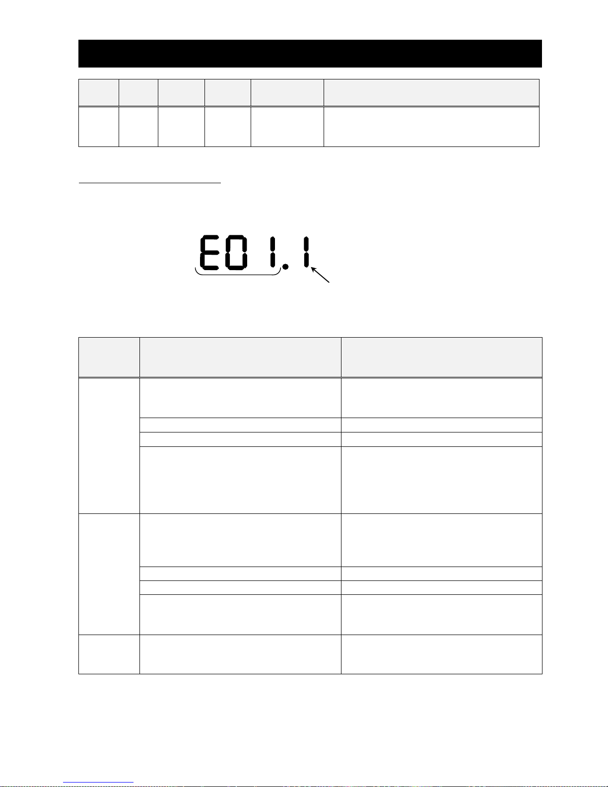
Chapter 9 Errors and Remedies
55
LINK /
ACT 1
LINK /
ACT 2
COMM
ERR
Description
Remarks
On
On
During
startup
WJ-PN is during startup.
WJ-PN can’t communicate with PROFINET
until WJ-PN has finished startup.
9.2 Inverter errors
When the inverter is in a tripped state, the inverter output turns O FF (trips), and the inverter
displays an error code.
The trip history monitor (d081 to d086) also displays the same error code as the inverter.
Error (trip) code Inverter’s condition of trip detected
Please refer to Chapter 6 “Troubleshooting and Maintenance” of the WJ200 / WL200 instruction
manual for “Error (trip) code” and “Inverter’s condition of trip detected.”
In an inverter tripped state using the WJ-PN, is the following table.
Display
and
indicators
Possible causes
Remedy
0.00
(Other
than trip
indication)
The Inverter does not power up
Follow the instructions provided in the
WJ200 / WL200 user’s manual to
troubleshoot.
The WJ-PN connector is damaged
Replace the WJ-PN.
The Inverter RS input is ON
Switch the Inverter RS input OFF.
Mapping “operator control (31)”,
“force terminal mode (51)”,
“multi-speed frequency 1 (02)” to the
input terminal. At least, the one of them
turns ON.
Turn them OFF.
E60.*
E69.*
The WJ-PN encountered a fatal error
during power up.
Turn it OFF instantly. Then, check that the
WJ-PN is mounted properly and restart
the WJ-PN. If the problem persists,
replace the WJ-PN.
The WJ-PN connector is damaged
Replace the WJ-PN.
The WJ-PN is disconnected.
Check that the WJ-PN is connected.
The WJ-PN encountered a fatal error
during Operation.
Check that the WJ-PN is mounted
properly and restart the WJ-PN. If the
problem persists, replace the WJ-PN.
E63.*
Communication error occurred between
the PROFINET IO controller and the
WJ-PN.
Check the connection between the
PROFINET IO controller and the WJ-PN.
NOTE: E60.* and E69.* are same error contents. E60.* error indicates that are detected in the WJ-PN.
E69.* error indicates that are detected in the inverter.
Page 62
Chapter 9 Errors and Remedies
56
Factor code list
No trip factor
0
Fin temperature error
21
Overcurrent protection during constant
speed
1
CPU communication error
22
Overcurrent protection during deceleration
2
Main circuit error
25
Overcurrent protection during acceleration
3
Driver error
30
Overcurrent protection during stop
4
Thermistor error
35
Overload protection
5
Break error addition
36
Braking resistor overload protection
6
Emergency trip
37
Overvoltage protection
7
The low-speed range overload
protection
38
EEPROM error
8
Operator bad connection
40
Under voltage protection
9
Easy sequence illegal instruction error
43
Current Transformer error
1
0
Easy sequence nesting error
44
CPU error
11 Easy sequence execution instruction
error
45
External trip
1
2
Easy sequence user trip 0 to 9
50 to
59
USP error
1
3
Option error 0 to 9
60 to
69
Grounding protection
1
4
Encoder disconnection
80
Incoming overvoltage protection
1
5
Acceleration
81
Temperature detection error
1
9
Trip position control range
83
Status code list
During reset
0
Operates at frequency = 0
5
During stop
1
During startup
6
During deceleration
2
DB active
7
At a constant speed
3
During overload limit
8
During acceleration
4
-
-
Page 63
Chapter 9 Errors and Remedies
57
9.3 Hint of the action by the combination with the WJ200
/ WL200
The inverter WJ200 / WL200 series has various items (parameters). Attention is necessary
because driving movement of the PROFINET changes depending on the items (parameters).
An example is shown below.
9.3.1 A002 (Run command source)
The behavior of WJ200 / WL200 is as follows when changed from OFF (shut off) to ON (enabled to
drive) when WJ200 / WL200 is used with Dip-Switch in the position to activate functional safety.
If either GS1 signal or GS2 signal is turned to OFF (shut off), the condition of the output is
continued to an interruption state.
It is to be known that approval by a third party for “STO” function is void even if the safety
function is activated with the Dip-Switch in the position to select functional safety (STO) when WJ-PN
is attached to WJ200 / WL200.
Please refer to [Functional Safety of WJ200 / WL200] in [Chapter 2.1 Outline of product].
Contents
OFF(inverter output is forbidden)→ON(inverter output is
allowed)
01 (control circuit terminal
block)
Driving restart
02 (digital operator)
stop (driving does not restart)
03 (Modbus)
Driving restart
04 (option)
Driving restart
Page 64
Chapter 9 Errors and Remedies
58
9.3.2 C102 (reset select)
Select the action of the reset terminal (RS) of the inverter.
By setting of C102, PROFINET communication continuation presence changes by the input of the
reset terminal (RS).
The action explanation is as follows.
Contents
Description
00
When the RS is turned ON, the inverter is restored from the trip state, and
communication between the inverter and WJ-PN suspends, and PROFINET
communication suspends.
(In normal state: the inverter output turns OFF
In trip state: the inverter is restored from a trip state.)
01
When the RS is turned OFF, the inverter is restored from the trip state, and
communication between the inverter and WJ-PN suspends, and PROFINET
communication suspends.
(In normal state: the inverter output turns OFF
In trip state: the inverter is restored from a trip state.)
02
When the RS is turned ON, the inverter is restored from the trip state, and
communication between the inverter and WJ-PN suspends, and PROFINET
communication suspends.
(In normal state: invalid (there is no change to the inverter)
In trip state: the inverter is restored from a trip state.)
03
When the RS is turned ON, the inverter is restored from the trip state, the communication
between WJ200 / WL200 and WJ-PN continues, the PROFINET communication
continues.
(In normal state: invalid (there is no change to the inverter)
In trip state: the inverter is restored from a trip state.)
9.3.3 Combination with EzSQ
Please be careful of the followings.
- Do not turn ON the logic input 5 (2CH) and the logic input 6 (HLD) with the EzSQ program.
- Do not assign jogging (JG) to the any logic inputs and turn ON its logic input.
- Do not write the parameter both via PROFINET and with EzSQ program at the same time. If you
do so, the 1st write access is overwritten by the 2nd write access.
9.3.4 Combination with external 24 V DC power supply
The inverter control section can be powered with external 24V DC power supply. This will allow you
to read and write parameters via PROFINET, but please be careful of the followings.
- Do not let inverter run.
- Do not turn off inverter immediately after you store to EEPROM of the inverter. The EEPROM
error (E08) may occur in the inverter.
Please refer to the instruction manual of WJ200 / WL200 about externally power 24 V DC.
Page 65

Chapter 9 Errors and Remedies
59
9.3.5 Control by frequency
You can control the inverter by not NSOLL_A / NIST_A but frequency. When you control the inverter
by frequency, you need to set the followings.
- Either Telegram 104 or 105 is used.
- Modbus register No. 0x1F14 is set to any one of P161 - P169.
- Modbus register No. 0x1001 and 0x1002 are set to any of P171 - P179 consecutively.
For example, when you set the following, the output frequency setting is 2nd byte of the message
data sent from the PROFINET IO controller to PROFINET IO device and the output frequency monitor
is 2nd and 3rd byte of the message data sent from the PROFINET IO device to the PROFINET IO
controller.
- Telegram 104
- P161 = 0x1F14
- P171 = 0x1001, P172 = 0x1002
Page 66
Chapter 9 Errors and Remedies
60
9.4 Hint of WJ-PN and PROFINET
9.4.1 The order of turning on the power of WJ-PN and the
PROFINET IO controller
The order of turning on the power of PROFINET IO controllers and PROFINET IO devices isn’t
defined in PROFINET. When both of a PROFINET IO controller and WJ-PN are turned on the power
and both of them are ready to PROFINET, they start to communicate of PROFINET. However, it may
take some time that a PROFINET IO controller prepares PROFINET. Please refer to the instruction
manual of the PROFINET IO controller for details.
9.4.2 Replacement of WJ-PN and WJ200 / WL200
When you replace WJ-PN and/or WJ200 / WL200, you need to set the device name
(NameOfStation) rightly. If you don’t set the right device name (NameOfStation), WJ-PN doesn’t
communicate.
When you replace WJ-PN, you need to set the device name (NameOfStation) the same setting of old
WJ-PN with an engineering tool.
When you replace WJ200 / WL200, you need to set the inverter parameters the same setting of old
WJ200 / WL200.
When you replace WJ-PN and WJ200 / WL200, you need to set both of them.
If WJ-PN doesn’t start to communicate by PROFINET after the replacement, please confirm the
PROFINET cable is connected right and turn off and on WJ-PN and WJ200 / WL200.
9.4.3 The initialization and the mode change of WJ200 / WL200
You can initialize and change the mode of WJ200 / WL200 even if WJ-PN is communicating. When
you initialize or change the mode while WJ-PN communicates, WJ-PN keeps communicating by
PROFINET. However, when you access the inverter parameters while WJ200 / WL200 is initializing,
WJ-PN returns the error code 0x65 of PROFIdrive.
You can initialize and change the mode of WJ200 / WL200 via PROFINET.
9.4.4 Network protocol analyzer
You can collect and analyze PROFINET communication log using a network protocol analyzer. It is
useful to investigate the unexpected phenomenon.
Recommended analyzers are the following.
Product name
Manufacturer
Type
Wireshark (PC application)
The Wireshark team
-
ET2000
Beckhoff
ET2000
Page 67
Chapter 9 Errors and Remedies
61
9.4.5 Technical support
To receive technical support for the Hitachi inverter you purchased, please be prepared to provide
the following information.
Contents
Note
The phenomenon and frequency
In as much detail as possible.
Type of WJ200 / WL200
Please refer to “1.2.1 Required
information for product inquiry” for
detail.
MFG No. of WJ-PN and WJ200 / WL200
Date of purchase WJ-PN and WJ200 / WL200
The setting of inverter parameters of WJ200 / WL200
The csv file saved with ProDriveNext is
desirable.
The PROFINET network layout
Include the node address of all
devices.
The PROFINET IO controller that you use
Manufacturer, Type
If there are other PROFINET IO devices, the
information of these PROFINET IO devices
If these PROFINET IO devices aren’t
WJ-PN, Manufacturer, Type of these
PROFINET IO devices.
The communication log when the phenomenon
occurred.
It is the communication log file saved
with the analyzer in “9.4.4 Network
protocol analyzer”.
Page 68
Chapter 10 WJ-PN Specification
62
10.1 WJ-PN Specifications
Item
Specification
Installation
Unit type
WJ200 / WL200 Series Option Board*1
Model
WJ-PN
Dimensions (W x H x D)
68 x 60 x 45[mm]
Weight
170[g] (typical)
Environment
Ambient operating
temperature
-10 to 50[degree] (no icing or condensation)
Ambient operating humidity
20 to 90[%], RH
Storage temperature
-20 to 65°C (no icing or condensation)
Vibration resistance
5.9[m/s2] (0.6[G]) at 10 to 55[Hz]
Dielectric strength
500[VAC] (between isolated circuits)
Conformance to EMC and
electrical safety standards
EN61800-3: 2004 / A1:2012 (2014/30/EU) First
environment, Category C1*2
EN61800-5-1: 2007 (2014/35/EU)
Enclosure rating
IP 20
PROFINET
Interface
Communications protocol
PROFINET IO Ver2.32
Device type
PROFINET IO Device
Conformance class
B
Protocol
DCP, LLDP, SNMP
Netload
I
RT / IRT
only RT
Profile
PROFIdrive
Physical layer
Auto negotiation
(100BASE-TX (IEEE802.3) only)
port
2 ports
Connector
RJ45 (Port1 / 2)
MAC address
3 (Host, Port 1 / 2)
Cable
100BX-TX supported (category 5e or higher)
STP cable (straight or cross allowed)
Communications distance
Distance between nodes: 100[m] max
PROFIdrive
Version
4.2
Application class
AC1 (Standard Drive)
Telegram
Standard telegram 1
WJ-PN telegram 103 (same as PPO3 of PROFIdrive
version 2)
WJ-PN telegram 104 (same as PPO4 of PROFIdrive
version 2)
WJ-PN telegram 105 (like PPO5 of PROFIdrive
version 2)
Configuring of telegram
From P160 to P179 of WJ200 / WL200 parameters
Operating mode
Speed control mode
Jogging
Only jogging 1 is supported.
Note1: When WJ-PN is attached to WJ200 / WL200, functional safety is not supported. Please refer
to “5.3 A system configuration of the PROFINET” for details.
Note2: C1 only when installed in a metal cabinet, otherwise C2.
Page 69
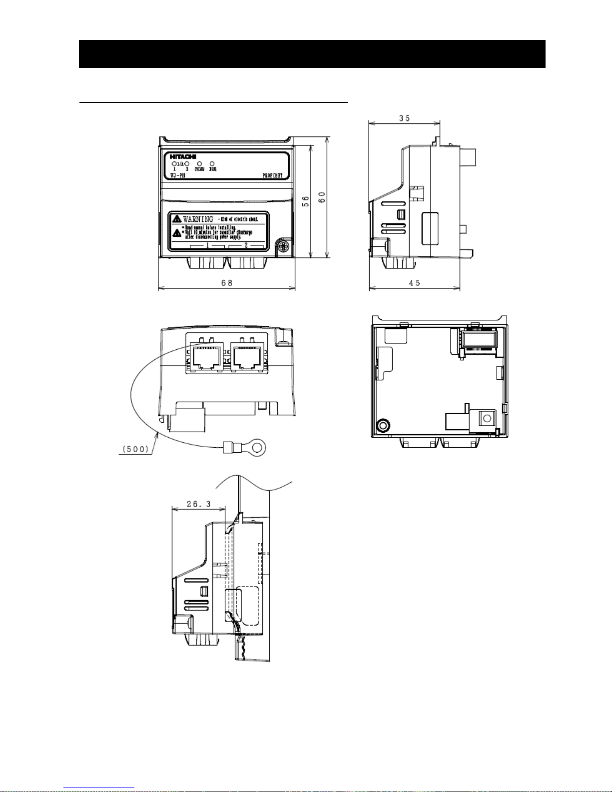
Chapter 10 WJ-PN Specification
63
10.2 Appearance and Dimensions
Unit [mm]
Page 70
Appendix PROFINET Object List
64
Appendix object list
Inverter parameters are allocated to objects 1000 to 1037 and 2000 to 2037.
1000 to 1037 are 2-byte parameters and 2000 to 2037 are 4-byte parameters.
The data in the table means the following.
- The data prefixed with "0x" means hexadecimal. From 'A' to 'F' are used to represent values from
10 to 15.
- The negative data are represented by two's complement.
- The other data is decimal.
Monitor mode: group d
Index
Sub-
index
Register
number
Size
[bite]
Function
code
Name
R/W
Description and range
Resolution
WJ200
only
2016
0x22
0x1001
04
(UDINT)
d001
Output
frequency
monitor
R
0 to 40000
0.01[Hz]
1016
0x24
0x1003
02
(UINT)
d002
Output
current
monitor
R
0 to 65530
0.01[A]
1016
0x25
0x1004
02
(UINT)
d003
Rotation
direction
monitor
R
0: forward
1: stop
2: reverse
-
2016
0x26
0x1005
04
(UDINT)
d004
Process
variable
(PV), PID
feedback
monitor
R
0 to 1000000
0.1
1016
0x28
0x1007
02
(UINT)
d005
Intelligent
input
terminal
status
R
20 : terminal 1
21 : terminal 2
22 : terminal 3
23 : terminal 4
24 : terminal 5
25 : terminal 6
26 : terminal 7
-
1016
0x29
0x1008
02
(UINT)
d006
Intelligent
output
terminal
status
R
20: terminal 11
21: terminal 12
26: relay
-
2016
0x2A
0x1009
04
(UDINT)
d007
Scaled
output
frequency
monitor
R
0 to 4000000
0.01
2016
0x2C
0x100B
04
(DINT)
d008
Actual
frequency
monitor
R
-40000 to 40000
0.01[Hz]
✔
1016
0x2E
0x100D
02
(INT)
d009
Torque
command
monitor
R
-200 to 200
1[%]
✔
Page 71
Appendix PROFINET Object List
65
Index
Sub-
index
Register
number
Size
[bite]
Function
code
Name
R/W
Description and range
Resolution
WJ200
only
1016
0x2F
0x100E
02
(INT)
d010
Torque bias
monitor
R
-200 to 200
1[%]
✔
1016
0x31
0x1010
02
(INT)
d012
Output
torque
monitor
R
-200 to 200
1[%]
✔
1016
0x32
0x1011
02
(UINT)
d013
Output
voltage
monitor
R
0 to 6000
0.1[V]
1016
0x33
0x1012
02
(UINT)
d014
Input power
monitor
R
0 to 1000
0.1[kW]
2016
0x34
0x1013
04
(UDINT)
d015
Watt-hour
monitor
R
0 to 99990000
0.1[kW]
2016
0x36
0x1015
04
(UDINT)
d016
Elapsed
RUN time
monitor
R
0 to 999000
1[h]
2016
0x38
0x1017
04
(UDINT)
d017
Elapsed
power-on
time
monitor
R
0 to 999000
1[h]
1016
0x3A
0x1019
02
(INT)
d018
Heat sink
temperature
monitor
R
-200 to 1500
0.1[℃]
1016
0x3E
0x101D
02
(UINT)
d022
Life check
monitor
R
20: Capacitor on the
main board
Bit
2016
0x57
0x1036
04
(DINT)
d029
Position
setting
monitor
R
-268435455 to
268435455
1 ✔ 2016
0x59
0x1038
04
(DINT)
d030
Position
feedback
monitor
R
-268435455 to
268435455
1
✔
1016
0x78
0x1057
02
(UINT)
d060
Inverter
mode
monitor
R
0: IM CT mode
3: PM motor
-
✔
1000
0x12
0x0011
02
(UINT)
d080
Trip
Counter
R
0 to 65530
-
1000
0x13
0x0012
02
(UINT)
d081
Trip
information
1 (factor)
R
Please refer to section
9, factor code list
-
1000
0x14
0x0013
02
(UINT)
d081
Trip
information
1 (inverter
status)
R
Please refer to section
9, status code list
-
2000
0x15
0x0014
04
(UDINT)
d081
Trip
information
1
(frequency)
R
Output frequency at
trip point
0.01[Hz]
Page 72
Appendix PROFINET Object List
66
Index
Sub-
index
Register
number
Size
[bite]
Function
code
Name
R/W
Description and range
Resolution
WJ200
only
1000
0x17
0x0016
02
(UINT)
d081
Trip
information
1 (current)
R
Motor current at trip
point
0.01[A]
1000
0x18
0x0017
02
(UINT)
d081
Trip
information
1 (voltage)
R
DC bus voltage at trip
point
0.1[V]
2000
0x19
0x0018
04
(UDINT)
d081
Trip
information
1 (running
time)
R
Cumulative inverter
operation time at trip
point
1[h]
2000
0x1B
0x001A
04
(UDINT)
d081
Trip
information
1 (power-on
time)
R
Cumulative power-ON
time at trip point
1[h]
1000
0x1D
0x001C
02
(UINT)
d082
Trip
information
2 (factor)
R
Please refer to section
9, factor code list
-
1000
0x1E
0x001D
02
(UINT)
d082
Trip
information
2 (inverter
status)
R
Please refer to section
9, status code list
- 2000
0x1F
0x001E
04
(UDINT)
d082
Trip
information
2
(frequency)
R
Output frequency at
trip point
0.01[Hz]
1000
0x21
0x0020
02
(UINT)
d082
Trip
information
2 (current)
R
Motor current at trip
point
0.01[A]
1000
0x22
0x0021
02
(UINT)
d082
Trip
information
2 (voltage)
R
DC bus voltage at trip
point
0.1[V]
2000
0x23
0x0022
04
(UDINT)
d082
Trip
information
2 (running
time)
R
Cumulative inverter
operation time at trip
point
1[h]
2000
0x25
0x0024
04
(UDINT)
d082
Trip
information
2 (power-on
time)
R
Cumulative power-ON
time at trip point
1[h]
1000
0x27
0x0026
02
(UINT)
d083
Trip
information
3 (factor)
R
Please refer to section
9, factor code list
-
1000
0x28
0x0027
02
(UINT)
d083
Trip
information
3 (inverter
status)
R
Please refer to section
9, status code list
-
Page 73
Appendix PROFINET Object List
67
Index
Sub-
index
Register
number
Size
[bite]
Function
code
Name
R/W
Description and range
Resolution
WJ200
only
2000
0x29
0x0028
04
(UDINT)
d083
Trip
information
3
(frequency)
R
Output frequency at
trip point
0.01[Hz]
1000
0x2B
0x002A
02
(UINT)
d083
Trip
information
3 (current)
R
Motor current at trip
point
0.01[A]
1000
0x2C
0x002B
02
(UINT)
d083
Trip
information
3 (voltage)
R
DC bus voltage at trip
point
0.1[V]
2000
0x2D
0x002C
04
(UDINT)
d083
Trip
information
3 (running
time)
R
Cumulative inverter
operation time at trip
point
1[h]
2000
0x2F
0x002E
04
(UDINT)
d083
Trip
information
3 (power-on
time)
R
Cumulative power-ON
time at trip point
1[h]
1000
0x31
0x0030
02
(UINT)
d084
Trip
information
4 (factor)
R
Please refer to section
9, factor code list
-
1000
0x32
0x0031
02
(UINT)
d084
Trip
information
4 (inverter
status)
R
Please refer to section
9, status code list
- 2000
0x33
0x0032
04
(UDINT)
d084
Trip
information
4
(frequency)
R
Output frequency at
trip point
0.01[Hz]
1000
0x35
0x0034
02
(UINT)
d084
Trip
information
4 (current)
R
Motor current at trip
point
0.01[A]
1000
0x36
0x0035
02
(UINT)
d084
Trip
information
4 (voltage)
R
DC bus voltage at trip
point
0.1[V]
2000
0x37
0x0036
04
(UDINT)
d084
Trip
information
4 (running
time)
R
Cumulative inverter
operation time at trip
point
1[h]
2000
0x39
0x0038
04
(UDINT)
d084
Trip
information
4 (power-on
time)
R
Cumulative power-ON
time at trip point
1[h]
1000
0x3B
0x003A
02
(UINT)
d085
Trip
information
5 (factor)
R
Please refer to section
9, factor code list
-
Page 74
Appendix PROFINET Object List
68
Index
Sub-
index
Register
number
Size
[bite]
Function
code
Name
R/W
Description and range
Resolution
WJ200
only
1000
0x3C
0x003B
02
(UINT)
d085
Trip
information
5 (inverter
status)
R
Please refer to section
9, status code list
-
2000
0x3D
0x003C
04
(UDINT)
d085
Trip
information
5
(frequency)
R
Output frequency at
trip point
0.01[Hz]
1000
0x3F
0x003E
02
(UINT)
d085
Trip
information
5 (current)
R
Motor current at trip
point
0.01[A]
1000
0x40
0x003F
02
(UINT)
d085
Trip
information
5 (voltage)
R
DC bus voltage at trip
point
0.1[V]
2000
0x41
0x0040
04
(UDINT)
d085
Trip
information
5 (running
time)
R
Cumulative inverter
operation time at trip
point
1[h]
2000
0x43
0x0042
04
(UDINT)
d085
Trip
information
5 (power-on
time)
R
Cumulative power-ON
time at trip point
1[h]
1000
0x45
0x0044
02
(UINT)
d086
Trip
information
6 (factor)
R
Please refer to section
9, factor code list
-
1000
0x46
0x0045
02
(UINT)
d086
Trip
information
6 (inverter
status)
R
Please refer to section
9, status code list
-
2000
0x47
0x0046
04
(UDINT)
d086
Trip
information
6
(frequency)
R
Output frequency at
trip point
0.01[Hz]
1000
0x49
0x0048
02
(UINT)
d086
Trip
information
6 (current)
R
Motor current at trip
point
0.01[A]
1000
0x4A
0x0049
02
(UINT)
d086
Trip
information
6 (voltage)
R
DC bus voltage at trip
point
0.1[V]
2000
0x4B
0x004A
04
(UDINT)
d086
Trip
information
6 (running
time)
R
Cumulative inverter
operation time at trip
point
1[h]
Page 75
Appendix PROFINET Object List
69
Index
Sub-
index
Register
number
Size
[bite]
Function
code
Name
R/W
Description and range
Resolution
WJ200
only
2000
0x4D
0x004B
04
(UDINT)
d086
Trip
information
6 (power-on
time)
R
Cumulative power-ON
time at trip point
1[h]
1000
0x4F
0x004E
02
(UINT)
d090
Warning
monitor
R
Warning code
-
1009
0x13
0x0900
02
(UINT)
-
Writing to
the
EEPROM
R/W
0: recalculation the
constant of the motor
1: stored the setting
value to the EEPROM
The others:
recalculation the
constant of the motor,
stored the setting
value to the EEPROM
-
-
1009
0x15
0x0902
02
(UINT)
-
Writing
mode
selection
R/W
0: writing enabled
1: writing disabled
- 1016
0x47
0x1026
02
(UINT)
d102
DC bus
voltage
monitor
R
0 to 10000
0.1[V]
1016
0x48
0x1027
02
(UINT)
d103
BRD load
ratio
monitor
R
0 to 1000
0.1[%]
1016
0x49
0x1028
02
(UINT)
d104
Electronic
thermal
monitor
R
0 to 1000
0.1[%]
Function mode: group F
Index
Sub-
index
Register
number
Size
[bite]
Function
code
Name
R/W
Description and
range
Resolution
WJ200
only
2000
0x02
0x0001
04
(UDINT)
F001
Output
frequency
setting
R/W
0 to the maximum
frequency (A004)
0.01[Hz]
2017
0x26
0x1103
04
(UDINT)
F002
Acceleration
(1) time
R/W
1 to 360000
0.01[s]
2017
0x28
0x1105
04
(UDINT)
F003
Deceleration
(1) time
R/W
1 to 360000
0.01[s]
1017
0x2A
0x1107
02
(UINT)
F004
Keypad Run
key routing
R/W
00: forward
01: reverse
-
2033
0x46
0x2103
04
(UDINT)
F202
Acceleration
(1) time,
2nd motor
R/W
1 to 360000
0.01[s]
Page 76
Appendix PROFINET Object List
70
Index
Sub-
index
Register
number
Size
[bite]
Function
code
Name
R/W
Description and
range
Resolution
WJ200
only
2033
0x48
0x2105
04
(UDINT)
F203
Deceleration
(1) time,
2nd motor
R/W
1 to 360000
0.01[s]
Function mode: group A
Index
Sub-
inde
x
Register
number
Size
[bite]
Functio
n
code
Name
R/W
Description and range
Resolutio
n
WJ200
only
1018
0x26
0x1201
02
(UINT)
A001
Frequency
source
R/W
00: volume
01: control terminal
02: function F001
setting
03: Modbus network
input
04: option board
06: pulse train input
07: EzSQ
10: calculate function
output
-
1018
0x27
0x1202
02
(UINT)
A002
Run
command
source
R/W
00: control terminal
01: run key on the
keypad, or digital
operator
02: Modbus network
input
03: option
-
1018
0x28
0x1203
02
(UINT)
A003
Base
frequency
R/W
300 to the maximum
frequency (A004)
0.1[Hz]
1018
0x29
0x1204
02
(UINT)
A004
Maximum
frequency
R/W
300 to 4000
0.1[Hz]
1018
0x2A
0x1205
02
(UINT)
A005
[AT]
selection
R/W
00: select between [O]
and [OI] at [AT] (ON =
OI, OFF = O)
02: select between [O]
and external POT at
[AT] (ON =POT, OFF =
O)
03: select between
[OI] and external POT
at [AT] (ON =POT, OFF
= OI)
-
2018
0x30
0x120B
04
(UDINT)
A011
[O] input
active range
start
frequency
R/W
0 to 40000
0.01[Hz]
Page 77
Appendix PROFINET Object List
71
Index
Subinde
x
Register
number
Size
[bite]
Functio
n
code
Name
R/W
Description and range
Resolutio
n
WJ200
only
2018
0x32
0x120D
04
(UDINT)
A012
[O] input
active range
end
frequency
R/W
0 to 40000
0.01[Hz]
1018
0x34
0x120F
02
(UINT)
A013
[O] input
active range
start voltage
R/W
0 to 100
1[%]
1018
0x35
0x1210
02
(UINT)
A014
[O] input
active range
end voltage
R/W
0 to 100
1[%]
1018
0x36
0x1211
02
(UINT)
A015
[O] input
start
frequency
enable
R/W
00: offset (A011
value)
01: 0[Hz]
-
1018
0x37
0x1212
02
(UINT)
A016
Analog
input filter
R/W
1 to 30: x 2[ms] filiter
31: 500[ms] fixed filter
with plus or minus
0.1[kHz] hysteresis
1
1019
0x3A
0x1215
02
(UINT)
A019
Multi-speed
operation
selection
R/W
00: binary operation
01: bit operation
-
2018
0x3B
0x1216
04
(UDINT)
A020
Multi-speed
frequency 0
R/W
0 or start frequency to
maximum frequency
(A004)
0.01[Hz]
2018
0x3
D
0x1218
04
(UDINT)
A021
Multi-speed
frequency 1
R/W
0 or start frequency to
the maximum
frequency (A004)
0.01[Hz]
2018
0x3F
0x121A
04
(UDINT)
A022
Multi-speed
frequency 2
R/W
0 or start frequency to
maximum frequency
(A004)
0.01[Hz]
2018
0x41
0x121C
04
(UDINT)
A023
Multi-speed
frequency 3
R/W
0 or start frequency to
maximum frequency
(A004)
0.01[Hz]
2018
0x43
0x121E
04
(UDINT)
A024
Multi-speed
frequency 4
R/W
0 or start frequency to
maximum frequency
(A004)
0.01[Hz]
2018
0x45
0x1220
04
(UDINT)
A025
Multi-speed
frequency 5
R/W
0 or start frequency to
maximum frequency
(A004)
0.01[Hz]
2018
0x47
0x1222
04
(UDINT)
A026
Multi-speed
frequency 6
R/W
0 or start frequency to
maximum frequency
(A004)
0.01[Hz]
2018
0x49
0x1224
04
(UDINT)
A027
Multi-speed
frequency 7
R/W
0 or start frequency to
maximum frequency
(A004)
0.01[Hz]
Page 78
Appendix PROFINET Object List
72
Index
Sub-
inde
x
Register
number
Size
[bite]
Functio
n
code
Name
R/W
Description and range
Resolutio
n
WJ200
only
2018
0x4B
0x1226
04
(UDINT)
A028
Multi-speed
frequency 8
R/W
0 or start frequency to
maximum frequency
(A004)
0.01[Hz]
2018
0x4
D
0x1228
04
(UDINT)
A029
Multi-speed
frequency 9
R/W
0 or start frequency to
maximum frequency
(A004)
0.01[Hz]
2018
0x4F
0x122A
04
(UDINT)
A030
Multi-speed
frequency
10
R/W
0 or start frequency to
maximum frequency
(A004)
0.01[Hz]
2018
0x51
0x122C
04
(UDINT)
A031
Multi-speed
frequency
11
R/W
0 or start frequency to
maximum frequency
(A004)
0.01[Hz]
2018
0x53
0x122E
04
(UDINT)
A032
Multi-speed
frequency
12
R/W
0 or start frequency to
maximum frequency
(A004)
0.01[Hz]
2018
0x55
0x1230
04
(UDINT)
A033
Multi-speed
frequency
13
R/W
0 or start frequency to
maximum frequency
(A004)
0.01[Hz]
2018
0x57
0x1232
04
(UDINT)
A034
Multi-speed
frequency
14
R/W
0 or start frequency to
maximum frequency
(A004)
0.01[Hz]
2018
0x59
0x1234
04
(UDINT)
A035
Multi-speed
frequency
15
R/W
0 or start frequency to
maximum frequency
(A004)
0.01[Hz]
1018
0x5
D
0x1238
02
(UINT)
A038
Jog
frequency
R/W
start frequency to
9.99
0.01[Hz]
1018
0x5E
0x1239
02
(UINT)
A039
Jog stop
mode
R/W
00: free-run stop
(invalid during run)
01: controlled
deceleration (invalid
during run)
02: DC breaking to
stop (invalid during
run)
03: free-run stop
(valid during run)
04: controlled
deceleration (valid
during run)
05: DC breaking to
stop (valid during run)
-
1018
0x60
0x123B
02
(UINT)
A041
Torque
boost select
R/W
00: manual torque
boost
01: automatic torque
boost
-
Page 79
Appendix PROFINET Object List
73
Index
Subinde
x
Register
number
Size
[bite]
Functio
n
code
Name
R/W
Description and range
Resolutio
n
WJ200
only
1018
0x61
0x123C
02
(UINT)
A042
Manual
torque
boost value
R/W
0 to 200
0.1[%]
1018
0x62
0x123D
02
(UINT)
A043
Manual
torque
boost
frequency
R/W
0 to 500
0.1[%]
1018
0x63
0x123E
02
(UINT)
A044
V/f
characterist
ic curve
R/W
00: constant torque
01: reduced torque
02: free V/f
03: sensorless vector
(SLV)
-
1018
0x64
0x123F
02
(UINT)
A045
V/f gain
R/W
20 to 100
1[%]
1018
0x65
0x1240
02
(UINT)
A046
Voltage
compensati
on gain for
automatic
torque
boost
R/W
0 to 255
1[%]
1018
0x66
0x1241
02
(UINT)
A047
Slip
compensati
on gain for
automatic
torque
boost
R/W
0 to 255
1[%]
1018
0x6A
0x1245
02
(UINT)
A051
DC braking
enable
R/W
00: disable
01: enable during stop
02: output frequency
(A052)
-
1018
0x6B
0x1246
02
(UINT)
A052
DC braking
frequency
R/W
0 to 6000
0.01[Hz]
1018
0x6C
0x1247
02
(UINT)
A053
DC braking
wait time
R/W
0 to 50
0.1[s]
1018
0x6
D
0x1248
02
(UINT)
A054
DC braking
force for
deceleratio
n
R/W
0 to 100
1[%]
1018
0x6E
0x1249
02
(UINT)
A055
DC braking
time for
deceleratio
n
R/W
0 to 600
0.1[s]
Page 80
Appendix PROFINET Object List
74
Index
Sub-
inde
x
Register
number
Size
[bite]
Functio
n
code
Name
R/W
Description and range
Resolutio
n
WJ200
only
1018
0x6F
0x124A
02
(UINT)
A056
DC braking
/ edge or
level
detection
for [DB]
input
R/W
00: edge detection
01: level detection
-
1018
0x70
0x124B
02
(UINT)
A057
DC braking
force at
start
R/W
0 to 100
1[%]
1018
0x71
0x124C
02
(UINT)
A058
DC braking
time at start
R/W
0 to 600
0.1[s]
1018
0x72
0x124D
02
(UINT)
A059
Carrier
frequency
during DC
braking
R/W
20 to 150
0.1[kHz]
2018
0x74
0x124F
04
(UDINT)
A061
Frequency
upper limit
R/W
0 or frequency lower
limit (A062) to the
maximum frequency
(A004)
0.01[Hz]
2018
0x76
0x1251
04
(UDINT)
A062
Frequency
lower limit
R/W
0 or start frequency
(b082) to frequency
upper limit (A061)
0.01[Hz]
2018
0x78
0x1253
04
(UDINT)
A063
Jump
frequency
(center) 1
R/W
0 to 40000
0.01[Hz]
1018
0x7A
0x1255
02
(UINT)
A064
Jump
frequency
width
(hysteresis)
1
R/W
0 to 1000
0.01[Hz]
2018
0x7B
0x1256
04
(UDINT)
A065
Jump
frequency
(center) 2
R/W
0 to 40000
0.01[Hz]
1018
0x7
D
0x1258
02
(UINT)
A066
Jump
frequency
width
(hysteresis)
2
R/W
0 to 1000
0.01[Hz]
2018
0x7E
0x1259
04
(UDINT)
A067
Jump
frequency
(center) 3
R/W
0 to 40000
0.01[Hz]
Page 81
Appendix PROFINET Object List
75
Index
Subinde
x
Register
number
Size
[bite]
Functio
n
code
Name
R/W
Description and range
Resolutio
n
WJ200
only
1018
0x80
0x125B
02
(UINT)
A068
Jump
frequency
width
(hysteresis)
3
R/W
0 to 1000
0.01[Hz]
2018
0x81
0x125C
04
(UDINT)
A069
Acceleratio
n hold
frequency
R/W
0 to 40000
0.01[Hz]
1018
0x83
0x125E
02
(UINT)
A070
Acceleratio
n hold time
R/W
0 to 600
0.1[s]
1018
0x84
0x125F
02
(UINT)
A071
PID select
R/W
00: disable
01: enable
02: enable with
reverse output
-
1018
0x85
0x1260
02
(UINT)
A072
PID
proportiona
l gain
R/W
2 to 2500
0.01
1018
0x86
0x1261
02
(UINT)
A073
PID integral
time
constant
R/W
0 to 36000
0.1[s]
1018
0x87
0x1262
02
(UINT)
A074
PID
derivative
time
constant
R/W
0 to 10000
0.01[s]
1018
0x88
0x1263
02
(UINT)
A075
PV scale
conversion
R/W
1 to 9999
0.01
1018
0x89
0x1264
02
(UINT)
A076
PV source
R/W
00: [OI] terminal
(current in)
01: [O] terminal
(voltage in)
02: Modbus network
03: Pulse train input
10: Calculate function
output
-
1018
0x8A
0x1265
02
(UINT)
A077
Reverse PID
action
R/W
00: disabled
01: enabled
- 1018
0x8B
0x1266
02
(UINT)
A078
PID output
limit
R/W
0 to 1000
0.1[%]
1018
0x8C
0x1267
02
(UINT)
A079
PID feed
forward
selection
R/W
00: disable
01: [O] terminal
(voltage in)
02: [OI] terminal
(current in)
-
Page 82
Appendix PROFINET Object List
76
Index
Sub-
inde
x
Register
number
Size
[bite]
Functio
n
code
Name
R/W
Description and range
Resolutio
n
WJ200
only
1018
0x8E
0x1269
02
(UINT)
A081
AVR
function
select
R/W
00: enabled
01: disabled
02: enabled except
during deceleration
-
1018
0x8F
0x126A
02
(UINT)
A082
AVR voltage
select
R/W
00: 200
01: 215
02: 220
03: 230
04: 240
1018
0x90
0x126B
02
(UINT)
A083
AVR filter
time
constant
R/W
0 to 10000
0.001[s]
1018
0x91
0x126C
02
(UINT)
A084
AVR
deceleratio
n gain
R/W
50 to 200
1[%]
1018
0x92
0x126D
02
(UINT)
A085
Energy-savi
ng
operation
mode
R/W
00: normal operation
01: energy-saving
operation
1018
0x93
0x126E
02
(UINT)
A086
Energy-savi
ng mode
tuning
R/W
0 to 1000
0.1[%]
2018
0x99
0x1274
04
(UDINT)
A092
Acceleratio
n time (2)
R/W
1 to 360000
0.01[s]
2018
0x9B
0x1276
04
(UDINT)
A093
Deceleratio
n time (2)
R/W
1 to 360000
0.01[s]
1018
0x9
D
0x1278
02
(UINT)
A094
Select
method to
switch to
Acc2/Dec2
profile
R/W
00: 2CH input from
the terminal
01: transition
frequency
02: forward and
reverse
2018
0x9E
0x1279
04
(UDINT)
A095
Acc1 to
Acc2
frequency
transition
point
R/W
0 to 40000
0.01[Hz]
2018
0xA0
0x127B
04
(UDINT)
A096
Dec1 to
Dec2
frequency
transition
point
R/W
0 to 40000
0.01[Hz]
Page 83
Appendix PROFINET Object List
77
Index
Subinde
x
Register
number
Size
[bite]
Functio
n
code
Name
R/W
Description and range
Resolutio
n
WJ200
only
1018
0xA2
0x127D
02
(UINT)
A097
Acceleratio
n curve
selection
R/W
00: linear
01: S-curve
02: U-curve
03: inverse U-curve
04: EL S-curve
-
1018
0xA3
0x127E
02
(UINT)
A098
Deceleratio
n curve
selection
R/W
00: linear
01: S-curve
02: U-curve
03: inverse U-curve
04: EL S-curve
-
2018
0xA6
0x1281
04
(UDINT)
A101
[OI] input
active range
start
frequency
R/W
0 to 40000
0.01[Hz]
2018
0xA8
0x1283
04
(UDINT)
A102
[OI] input
active range
end
frequency
R/W
0 to 40000
0.01[Hz]
1018
0xAA
0x1285
02
(UINT)
A103
[OI] input
active range
start
current
R/W
0 to 100
1[%]
1018
0xAB
0x1286
02
(UINT)
A104
[OI] input
active range
end current
R/W
0 to 100
1[%]
1018
0xAC
0x1287
02
(UINT)
A105
[OI] input
start
frequency
select
R/W
00: offset (A101
value)
01: 0[Hz]
-
1018
0xCA
0x12A5
02
(UINT)
A131
Acceleratio
n curve
constant
R/W
01 to 10
-
1018
0xC
B
0x12A6
02
(UINT)
A132
Deceleratio
n curve
constant
R/W
01 to 10
-
1018
0xD
4
0x12AF
02
(UINT)
A141
A input
select for
calculate
function
R/W
00: operator
01: volume
02: terminal [O] input
03: terminal [OI] input
04: Modbus network
05: option
07: pulse train input
-
Page 84
Appendix PROFINET Object List
78
Index
Sub-
inde
x
Register
number
Size
[bite]
Functio
n
code
Name
R/W
Description and range
Resolutio
n
WJ200
only
1018
0xD
5
0x12B0
02
(UINT)
A142
B input
select for
calculate
function
R/W
00: operator
01: volume
02: terminal [O] input
03: terminal [OI] input
04: Modbus network
05: option
07: pulse train input
1018
0xD
6
0x12B1
02
(UINT)
A143
Calculation
symbol
R/W
00: ADD (A141 +
A142)
01: SUB (A141 A142)
02: MUL (A141 x
A142)
-
2018
0xD
8
0x12B3
04
(UDINT)
A145
ADD
frequency
R/W
0 to 40000
0.01[Hz]
1018
0xD
A
0x12B5
02
(UINT)
A146
ADD
direction
select
R/W
00: plus (output
frequency + A145)
01: minus (output
frequency - A145)
-
1018
0xDE
0x12B9
02
(UINT)
A150
Curvature
of
EL-S-curve
at the start
of
acceleratio
n
R/W
0 to 50
1[%]
✔
1018
0xDF
0x12BA
02
(UINT)
A151
Curvature
of
EL-S-curve
at the end
of
acceleratio
n
R/W
0 to 50
1[%]
✔
1018
0xE0
0x12BB
02
(UINT)
A152
Curvature
of
EL-S-curve
at the start
of
deceleratio
n
R/W
0 to 50
1[%]
✔
Page 85
Appendix PROFINET Object List
79
Index
Subinde
x
Register
number
Size
[bite]
Functio
n
code
Name
R/W
Description and range
Resolutio
n
WJ200
only
1018
0xE1
0x12BC
02
(UINT)
A153
Curvature
of
EL-S-curve
at the end
of
deceleratio
n
R/W
0 to 50
1[%]
✔
2018
0xE2
0x12BD
04
(UDINT)
A154
Deceleratio
n hold
frequency
R/W
0 to 40000
0.01[Hz]
1018
0xE4
0x12BF
02
(UINT)
A155
Deceleratio
n hold time
R/W
0 to 600
0.1[s]
2018
0xE5
0x12C0
04
(UDINT)
A156
PID sleep
function
action
threshold
R/W
0 to 40000
0.01[Hz]
1018
0xE7
0x12C2
02
(UINT)
A157
PID sleep
function
action delay
time
R/W
0 to 255
0.1[s]
2018
0xEB
0x12C6
04
(UDINT)
A161
[VR] input
active range
start
frequency
R/W
0 to 40000
0.01[Hz]
2018
0xED
0x12C8
04
(UDINT)
A162
[VR] input
active range
end
frequency
R/W
0 to 40000
0.01[Hz]
1018
0xEF
0x12CA
02
(UINT)
A163
[VR] input
active range
start %
R/W
0 to 100
1[%]
1018
0xF0
0x12CB
02
(UINT)
A164
[VR] input
active range
end %
R/W
0 to 100
1[%]
1018
0xF1
0x12CC
02
(UINT)
A165
[VR] input
start
frequency
select
R/W
00: offset (A161
value)
01: 0 [Hz]
-
Page 86
Appendix PROFINET Object List
80
Index
Sub-
inde
x
Register
number
Size
[bite]
Functio
n
code
Name
R/W
Description and range
Resolutio
n
WJ200
only
1034
0x46
0x2201
02
(UINT)
A201
Frequency
source, 2nd
motor
R/W
00: volume
01: control terminal
02: function F001
setting
03: Modbus network
input
04: option board
06: pulse train input
07: EzSQ
10: calculate function
output
-
1034
0x47
0x2202
02
(UINT)
A202
Run
command
source, 2nd
motor
R/W
00: control terminal
01: run key on the
keypad, or digital
operator
02: Modbus network
input
03: option
-
1034
0x48
0x2203
02
(UINT)
A203
Base
frequency,
2nd motor
R/W
300 to the 2nd
maximum frequency
(A204)
0.1[Hz]
1034
0x49
0x2204
02
(UINT)
A204
Maximum
frequency,
2nd motor
R/W
300 to 4000
0.1[Hz]
2034
0x5B
0x2216
04
(UDINT)
A220
Multi-speed
frequency
0,
2nd motor
R/W
0 or start frequency to
the 2nd maximum
frequency (A204)
0.01[Hz]
1034
0x80
0x223B
02
(UINT)
A241
Torque
boost
select, 2nd
motor
R/W
00: manual torque
boost
01: automatic torque
boost
-
1034
0x81
0x223C
02
(UINT)
A242
Manual
torque
boost value,
2nd motor
R/W
0 to 200
0.1[%]
1034
0x82
0x223D
02
(UINT)
A243
Manual
torque
boost
frequency,
2nd motor
R/W
0 to 500
0.1[%]
Page 87
Appendix PROFINET Object List
81
Index
Subinde
x
Register
number
Size
[bite]
Functio
n
code
Name
R/W
Description and range
Resolutio
n
WJ200
only
1034
0x83
0x223E
02
(UINT)
A244
V/f
characterist
ic curve,
2nd motor
R/W
00: constant torque
01: reduced torque
02: free V/f
03: sensorless vector
(SLV)
-
1034
0x84
0x223F
02
(UINT)
A245
V/f gain, 2nd
motor
R/W
20 to 100
1[%]
1034
0x85
0x2240
02
(UINT)
A246
Voltage
compensati
on gain for
automatic
torque
boost, 2nd
motor
R/W
0 to 255
1[%]
1034
0x86
0x2241
02
(UINT)
A247
Slip
compensati
on gain for
automatic
torque
boost, 2nd
motor
R/W
0 to 255
1[%]
2034
0x94
0x224F
04
(UDINT)
A261
Frequency
upper limit,
2nd motor
R/W
0 or frequency lower
limit (A062) to the 2nd
maximum frequency
(A204)
0.01[Hz]
2034
0x96
0x2251
04
(UDINT)
A262
Frequency
lower limit,
2nd motor
R/W
0 or start frequency
(B082) to frequency
upper limit 2nd motor
(A261)
0.01[Hz]
1034
0xAE
0x2269
02
(UINT)
A281
AVR
function
select,
2nd motor
R/W
00: enabled
01: disabled
02: enabled except
during deceleration
-
1034
0xAF
0x226A
02
(UINT)
A282
AVR voltage
select,
2nd motor
R/W
00: 200
01: 215
02: 220
03: 230
04: 240
-
2034
0xB4
0x226F
04
(UDINT)
A292
Acceleratio
n time (2),
2nd motor
R/W
1 to 360000
0.01[s]
2034
0xB6
0x2271
04
(UDINT)
A293
Deceleratio
n time (2),
2nd motor
R/W
1 to 360000
0.01[s]
Page 88
Appendix PROFINET Object List
82
Index
Sub-
inde
x
Register
number
Size
[bite]
Functio
n
code
Name
R/W
Description and range
Resolutio
n
WJ200
only
1034
0xB8
0x2273
02
(UINT)
A294
Select
method to
switch to
Acc2/Dec2
profile, 2nd
motor
R/W
00: 2CH input from
the terminal
01: transition
frequency
02: forward and
reverse
- 2034
0xB9
0x2274
04
(UDINT)
A295
Acc1 to
Acc2
frequency
transition
point, 2nd
motor
R/W
0 to 40000
0.01[Hz]
2034
0xBB
0x2276
04
(UDINT)
A296
Dec1 to
Dec2
frequency
transition
point, 2nd
motor
R/W
0 to 40000
0.01[Hz]
Function mode: group b
Index
Sub-
inde
x
Register
number
Size
[bite]
Functio
n
code
Name
R/W
Description and range
Resolutio
n
WJ200
only
1019
0x28
0x1301
02
(UINT)
b001
Restart
mode on
power
failure /
under-volta
ge trip
R/W
00: alarm output after
trip, no automatic
restart.
01: restart at 0[Hz]
02: resume operation
after frequency
matching.
03: resume previous
frequency after
frequency matching,
then decelerate to
stop and display trip
information
04: resume operation
after active frequency
matching
-
1019
0x29
0x1302
02
(UINT)
b002
Allowable
under-volta
ge power
failure time
R/W
3 to 250
0.1[s]
Page 89
Appendix PROFINET Object List
83
Index
Subinde
x
Register
number
Size
[bite]
Functio
n
code
Name
R/W
Description and range
Resolutio
n
WJ200
only
1019
0x2A
0x1303
02
(UINT)
b003
Retry wait
time before
motor
restart
R/W
3 to 1000
0.1[s]
1019
0x2B
0x1304
02
(UINT)
b004
Instantaneo
us power
failure /
under-volta
ge trip
alarm
enable
R/W
00: disabled
01: enabled
02: disabled during
stop and decelerates
to a stop
-
1019
0x2C
0x1305
02
(UINT)
b005
Number of
restarts on
power
failure /
under-volta
ge trip
events
R/W
00: restart 16 times
01: always restart
-
2019
0x2E
0x1307
04
(UDINT)
b007
Restart
frequency
threshold
R/W
0 to 40000
0.01[Hz]
1019
0x30
0x1309
02
(UINT)
b008
Restart
mode on
over voltage
/ over
current trip
R/W
00: alarm output after
trip, no automatic
restart.
01: restart at 0[Hz]
02: resume operation
after frequency
matching.
03: resume previous
frequency after
frequency matching,
then decelerate to
stop and display trip
information
04: resume operation
after active frequency
matching
-
1019
0x32
0x130B
02
(UINT)
b010
Number of
retry on
over voltage
/ over
current trip
R/W
1 to 3
1[times]
Page 90
Appendix PROFINET Object List
84
Index
Sub-
inde
x
Register
number
Size
[bite]
Functio
n
code
Name
R/W
Description and range
Resolutio
n
WJ200
only
1019
0x33
0x130C
02
(UINT)
b011
Retry wait
time on
over voltage
/ over
current trip
R/W
3 to 1000
0.1[s]
1019
0x34
0x130D
02
(UINT)
b012
Level of
electronic
thermal
R/W
200 to 1000
0.1[%]
1019
0x35
0x130E
02
(UINT)
b013
Electronic
thermal
characterist
ic
R/W
00: reduced torque
01: constant torque
02: free setting
-
1019
0x37
0x1310
02
(UINT)
b015
Free setting
electronic
thermal
frequency 1
R/W
0 to 400
1[Hz]
1019
0x38
0x1311
02
(UINT)
b016
Free setting
electronic
thermal
current 1
R/W
0 to 1000
0.1[%]
1019
0x39
0x1312
02
(UINT)
b017
Free setting
electronic
thermal
frequency 2
R/W
0 to 400
1[Hz]
1019
0x3A
0x1313
02
(UINT)
b018
Free setting
electronic
thermal
current 2
R/W
0 to 1000
0.1[%]
1019
0x3B
0x1314
02
(UINT)
b019
Free setting
electronic
thermal
frequency 3
R/W
0 to 400
1[Hz]
1019
0x3C
0x1315
02
(UINT)
b020
Free setting
electronic
thermal
current 3
R/W
0 to 1000
0.1[%]
Page 91
Appendix PROFINET Object List
85
Index
Subinde
x
Register
number
Size
[bite]
Functio
n
code
Name
R/W
Description and range
Resolutio
n
WJ200
only
1019
0x3
D
0x1316
02
(UINT)
b021
Overload
restriction
operation
mode
R/W
00: disabled
01: enabled for
acceleration and
constant speed
02: enabled for
constant speed only
03: enabled for
acceleration and
constant speed,
increase speed at
regeneration
-
1019
0x3E
0x1317
02
(UINT)
b022
Overload
restriction
level
R/W
200 to 2000
0.1[%]
1019
0x3F
0x1318
02
(UINT)
b023
Deceleratio
n rate at
overload
restriction
R/W
1 to 30000
0.1[s]
1019
0x40
0x1319
02
(UINT)
b024
Overload
restriction
operation
mode 2
R/W
00: disabled
01: enabled for
acceleration and
constant speed
02: enabled for
constant speed only
03: enabled for
acceleration and
constant speed,
increase speed at
regeneration
-
1019
0x41
0x131A
02
(UINT)
b025
Overload
restriction
level 2
R/W
200 to 2000
0.1[%]
1019
0x42
0x131B
02
(UINT)
b026
Deceleratio
n rate 2 at
overload
restriction
R/W
1 to 30000
0.1[s]
1019
0x43
0x131C
02
(UINT)
b027
OC
suppression
selection
R/W
00: disabled
01: enabled
-
1019
0x44
0x131D
02
(UINT)
b028
Current
level of
active freq.
matching
R/W
200 to 2000
0.1[%]
Page 92
Appendix PROFINET Object List
86
Index
Sub-
inde
x
Register
number
Size
[bite]
Functio
n
code
Name
R/W
Description and range
Resolutio
n
WJ200
only
1019
0x45
0x131E
02
(UINT)
b029
Deceleratio
n rate of
active freq.
matching
R/W
1 to 30000
0.1[s]
1019
0x46
0x131F
02
(UINT)
b030
Start freq.
of active
freq.
matching
R/W
00: frequency at
previous shutoff
01: start from the
maximum frequency
02: start from set
frequency
-
1019
0x47
0x1320
02
(UINT)
b031
Software
lock mode
selection
R/W
00: all parameters
except b031 are
locked when [SFT]
terminal is ON
01: all parameters
except b031 and
output frequency
F001 are locked when
[SFT] terminal is ON
02: all parameters
except b031 are
locked
03: all parameters
except b031 and
output frequency
F001 are locked
10: high level access
including b031
-
1019
0x49
0x1322
02
(UINT)
b033
Motor cable
length
parameter
R/W
5 to 20
-
2019
0x4A
0x1323
04
(UDINT)
b034
Run/power
ON warning
time
R/W
0 to 65535
10[h]
1019
0x4C
0x1325
02
(UINT)
b035
Rotation
direction
restriction
R/W
00: no restriction
01: reverse rotation is
restricted
02: forward rotation is
restricted
1019
0x4
D
0x1326
02
(UINT)
b036
Reduced
voltage start
selection
R/W
0 to 255
1
Page 93
Appendix PROFINET Object List
87
Index
Subinde
x
Register
number
Size
[bite]
Functio
n
code
Name
R/W
Description and range
Resolutio
n
WJ200
only
1019
0x4E
0x1327
02
(UINT)
b037
Function
code
display
restriction
R/W
00: full display
01: function-specific
display
02: user setting (and
B037)
03: data comparison
display
04: basic display
05: monitor display
only
-
1019
0x4F
0x1328
02
(UINT)
b038
Initial
display
selection
R/W
000: intial display
selction by SET key
001 to 060: d001 to
d060
201: F001
-
1019
0x50
0x1329
02
(UINT)
b039
Automatic
user
parameter
registration
R/W
00: disabled
01: enabled
-
1019
0x51
0x132A
02
(UINT)
b040
Torque limit
selection
R/W
00: quadrant-specific
setting mode
01: terminal-switching
mode
02: analog voltage
input mode [O]
03: option board
-
✔
1019
0x52
0x132B
02
(UINT)
b041
Torque limit
1
(fwd/power
)
R/W
0 to 200 / 255 (no)
1[%]
✔
1019
0x53
0x132C
02
(UINT)
b042
Torque limit
2
(rev/regen.)
R/W
0 to 200 / 255 (no)
1[%]
✔
1019
0x54
0x132D
02
(UINT)
b043
Torque limit
3
(rev/power)
R/W
0 to 200 / 255(no)
1[%]
✔
1019
0x55
0x132E
02
(UINT)
b044
Torque limit
4
(fwd/regen.
)
R/W
0 to 200 / 255(no)
1[%]
✔
1019
0x56
0x132F
02
(UINT)
b045
Torque LAD
STOP
selection
R/W
00: disabled
01: enabled
-
✔
1019
0x57
0x1330
02
(UINT)
b046
Reverse run
protection
R/W
00: disabled
01: enabled
-
✔
Page 94
Appendix PROFINET Object List
88
Index
Sub-
inde
x
Register
number
Size
[bite]
Functio
n
code
Name
R/W
Description and range
Resolutio
n
WJ200
only
1019
0x5A
0x1333
02
(UINT)
b049
Dual Rating
Selection
R/W
Do not use this object.
-
✔
1019
0x5B
0x1334
02
(UINT)
b050
Controlled
deceleratio
n on power
loss
R/W
00: disabled
01: enabled
(decelerates to a stop)
02: enabled
(decelerates to a stop
with DC bus voltage
controlled)
03: enabled
(decelerates to a stop
with DC bus voltage
controlled, then
restart)
-
1019
0x5C
0x1335
02
(UINT)
b051
DC bus
voltage
trigger level
of ctrl.
decel.
R/W
0 to 10000
0.1[V]
1019
0x5
D
0x1336
02
(UINT)
b052
Over-voltag
e threshold
of ctrl.
decel.
R/W
0 to 10000
0.1[V]
2019
0x5E
0x1337
04
(UDINT)
b053
Deceleratio
n time of
ctrl. decel.
R/W
1 to 360000
0.01[s]
1019
0x60
0x1339
02
(UINT)
b054
Initial freq.
drop of ctrl.
decel.
R/W
0 to 1000
0.01[Hz]
1019
0x66
0x133F
02
(UINT)
b060
Maximum-li
mit level of
window
comparator
(O)
R/W
0 to 100
(minimum-limit level:
b061 + b062 * 2)[%]
1[%]
1019
0x67
0x1340
02
(UINT)
b061
Minimum-li
mit level of
window
comparator
(O)
R/W
0 to 100
(maximum-limit level:
b060 - b062 * 2)[%]
1[%]
1019
0x68
0x1341
02
(UINT)
b062
Hysteresis
width of
window
comparator
(O)
R/W
0 to 10
(maximum-limit level:
(b061 - b062) / 2)[%]
1[%]
Page 95
Appendix PROFINET Object List
89
Index
Subinde
x
Register
number
Size
[bite]
Functio
n
code
Name
R/W
Description and range
Resolutio
n
WJ200
only
1019
0x69
0x1342
02
(UINT)
b063
Maximum-li
mit level of
window
comparator
(OI)
R/W
0 to 100
(minimum-limit level:
b064 + b066 * 2)[%]
1[%]
1019
0x6A
0x1343
02
(UINT)
b064
Minimum-li
mit level of
window
comparator
(OI)
R/W
0 to 100
(maximum-limit level:
b063 - b066 * 2)[%]
1[%]
1019
0x6B
0x1344
02
(UINT)
b065
Hysteresis
width of
window
comparator
(OI)
R/W
0 to 10
(maximum-limit level:
(b063 - b064) / 2)[%]
1[%]
1019
0x70
0x1349
02
(UINT)
b070
Operation
level at O
disconnecti
on
R/W
0 to 100 / 255(no)
1[%]
1019
0x71
0x134A
02
(UINT)
b071
Operation
level at OI
disconnecti
on
R/W
0 to 100 / 255(no)
1[%]
1019
0x75
0x134E
02
(UINT)
b075
Ambient
temperatur
e setting
R/W
-10 to 50
1[℃]
1019
0x78
0x1351
02
(UINT)
b078
Watt-hour
clearance
R/W
00: OFF
01: ON (press STR
then clear)
-
1019
0x79
0x1352
02
(UINT)
b079
Watt-hour
display gain
R/W
1 to 1000
1
1019
0x7C
0x1355
02
(UINT)
b082
Start
frequency
R/W
10 to 999
0.01[Hz]
1019
0x7
D
0x1356
02
(UINT)
b083
Carrier
frequency
R/W
20 to 150
0.1[kHz]
Page 96
Appendix PROFINET Object List
90
Index
Sub-
inde
x
Register
number
Size
[bite]
Functio
n
code
Name
R/W
Description and range
Resolutio
n
WJ200
only
1019
0x7E
0x1357
02
(UINT)
b084
Initializatio
n mode
(parameters
or trip
history)
R/W
00: initialization
disabled
01: clears trip history
02: initializes all
parameters
03: clears trip history
and initialize all
parameters
04: clears tip history
and initializes all
parameters and EZSQ
program
-
1019
0x7F
0x1358
02
(UINT)
b085
Country for
initialization
R/W
00: mode 0
01: mode 1
-
1019
0x80
0x1359
02
(UINT)
b086
Frequency
scaling
conversion
factor
R/W
1 to 9999
0.01
1019
0x81
0x135A
02
(UINT)
b087
STOP key
enable
R/W
00: enabled
01: disabled
02: enabled only reset
-
1019
0x82
0x135B
02
(UINT)
b088
Restart
mode after
FRS
R/W
00: restart from 0[Hz]
01: restart form
frequency detected
from real speed of
motor (frequency
matching)
02: restart from
frequency detected
from real speed of
motor (active
frequency matching)
-
1019
0x83
0x135C
02
(UINT)
b089
Automatic
carrier
frequency
reduction
R/W
00: disabled
01: enabled,
depending on the
output current
02: enabled,
depending on the
heat-sink temperature
-
1019
0x84
0x135D
02
(UINT)
b090
Dynamic
braking
usage ratio
R/W
0 to 1000
0.1[%]
Page 97
Appendix PROFINET Object List
91
Index
Subinde
x
Register
number
Size
[bite]
Functio
n
code
Name
R/W
Description and range
Resolutio
n
WJ200
only
1019
0x85
0x135E
02
(UINT)
b091
Stop mode
selection
R/W
00: DEC (decelerate
to stop)
01: FRS (free-run to
stop)
-
1019
0x86
0x135F
02
(UINT)
b092
Cooling fan
control
R/W
disabled
-
1019
0x87
0x1360
02
(UINT)
b093
Clear
elapsed
time of
cooling fan
R/W
disabled
-
1019
0x88
0x1361
02
(UINT)
b094
Initializatio
n target
data
R/W
00: all parameters
01: all parameters
except in/output
terminals and
communication.
02: only registered
parameters in U****
03: all parameters
except registered
parameters in U*** and
b037
-
1019
0x89
0x1362
02
(UINT)
b095
Dynamic
braking
control
(BRD)
selection
R/W
00: disabled
01: enable during run
only
02: enable always
-
1019
0x8A
0x1363
02
(UINT)
b096
BRD
activation
level
R/W
330 to 380
1[V]
1019
0x8B
0x1364
02
(UINT)
b097
BRD
resistor
value
R/W
Minimum
resistance[ohm] to
600.0[ohm]
0.1[ohm]
1019
0x8E
0x1367
02
(UINT)
b100
Free V/F
setting,
freq.1
R/W
0 to free V/F setting,
frequency 2 (b102)
1[Hz]
1019
0x8F
0x1368
02
(UINT)
b101
Free V/F
setting,
voltage.1
R/W
0 to 8000
0.1[V]
1019
0x90
0x1369
02
(UINT)
b102
Free V/F
setting,
freq.2
R/W
0 to free V/F setting,
frequency 3 (b104)
1[Hz]
1019
0x91
0x136A
02
(UINT)
b103
Free V/F
setting,
voltage.2
R/W
0 to 8000
0.1[V]
Page 98
Appendix PROFINET Object List
92
Index
Sub-
inde
x
Register
number
Size
[bite]
Functio
n
code
Name
R/W
Description and range
Resolutio
n
WJ200
only
1019
0x92
0x136B
02
(UINT)
b104
Free V/F
setting,
freq.3
R/W
0 to free V/F setting,
frequency 4 (b106)
1[Hz]
1019
0x93
0x136C
02
(UINT)
b105
Free V/F
setting,
voltage.3
R/W
0 to 8000
0.1[V]
1019
0x94
0x136D
02
(UINT)
b106
Free V/F
setting,
freq.4
R/W
0 to free V/F setting,
frequency 5 (b108)
1[Hz]
1019
0x95
0x136E
02
(UINT)
b107
Free V/F
setting,
voltage.4
R/W
0 to 8000
0.1[V]
1019
0x96
0x136F
02
(UINT)
b108
Free V/F
setting,
freq.5
R/W
0 to free V/F setting,
frequency 6 (b110)
1[Hz]
1019
0x97
0x1370
02
(UINT)
b109
Free V/F
setting,
voltage.5
R/W
0 to 8000
0.1[V]
1019
0x98
0x1371
02
(UINT)
b110
Free V/F
setting,
freq.6
R/W
0 to free V/F setting,
frequency 7 (b112)
1[Hz]
1019
0x99
0x1372
02
(UINT)
b111
Free V/F
setting,
voltage.6
R/W
0 to 8000
0.1[V]
1019
0x9A
0x1373
02
(UINT)
b112
Free V/F
setting,
freq.7
R/W
0 to 400
1[Hz]
1019
0x9B
0x1374
02
(UINT)
b113
Free V/F
setting,
voltage.7
R/W
0 to 8000
0.1[V]
1019
0xA2
0x137B
02
(UINT)
b120
Brake
control
enable
R/W
00: disabled
01: enabled
- 1019
0xA3
0x137C
02
(UINT)
b121
Brake Wait
Time for
Release
R/W
0 to 500
0.01[s]
1019
0xA4
0x137D
02
(UINT)
b122
Brake Wait
Time for
Acceleratio
n
R/W
0 to 500
0.01[s]
1019
0xA5
0x137E
02
(UINT)
b123
Brake Wait
Time for
Stopping
R/W
0 to 500
0.01[s]
Page 99
Appendix PROFINET Object List
93
Index
Subinde
x
Register
number
Size
[bite]
Functio
n
code
Name
R/W
Description and range
Resolutio
n
WJ200
only
1019
0xA6
0x137F
02
(UINT)
b124
Brake Wait
Time for
Confirmatio
n
R/W
0 to 500
0.01[s]
1019
0xA7
0x1380
02
(UINT)
b125
Brake
release
freq.
R/W
0 to 400
0.01[Hz]
1019
0xA8
0x1381
02
(UINT)
b126
Brake
release
current
R/W
0 to 2000
0.1[%]
1019
0xA9
0x1382
02
(UINT)
b127
Braking
freq. setting
R/W
0 to 40000
0.01[Hz]
1019
0xAC
0x1385
02
(UINT)
b130
Deceleratio
n
overvoltage
suppression
enable
R/W
00: disabled
01: enabled
02: enabled with
acceleration
-
1019
0xA
D
0x1386
02
(UINT)
b131
Decel.
overvolt.
suppress
level
R/W
330 to 390
1[V]
1019
0xAE
0x1387
02
(UINT)
b132
Decel.
overvolt.
suppress
const.
R/W
10 to 3000
0.01[s]
1019
0xAF
0x1388
02
(UINT)
b133
Decel.
overvolt.
suppress
proportiona
l gain
R/W
0 to 500
0.01
1019
0xB0
0x1389
02
(UINT)
b134
Decel.
overvolt.
suppress
integral
time
R/W
0 to 1500
0.1[s]
1019
0xBB
0x1394
02
(UINT)
b145
GS input
mode
R/W
00: no trip (hardware
shutoff only)
01: trip
- 1019
0xC0
0x1399
02
(UINT)
b150
Display
ex.operator
connected
R/W
1 to 0x60
(d001 to d060)
-
1019
0xCA
0x13A3
02
(UINT)
b160
1st
parameter
of Dual
Monitor
R/W
1 to 0x30
(d001 to d030)
-
Page 100
Appendix PROFINET Object List
94
Index
Sub-
inde
x
Register
number
Size
[bite]
Functio
n
code
Name
R/W
Description and range
Resolutio
n
WJ200
only
1019
0xC
B
0x13A4
02
(UINT)
b161
2nd
parameter
of Dual
Monitor
R/W
1 to 0x30
(d001 to d030)
1019
0xC
D
0x13A5
02
(UINT)
b163
Frequency
set in
monitoring
R/W
00: disabled
01: enabled
-
1019
0xCE
0x13A6
02
(UINT)
b164
Automatic
return to
the initial
display
R/W
00: disabled
01: enabled
-
1019
0xCF
0x13A7
02
(UINT)
b165
Ex. operator
com. loss
action
R/W
00: trip
01: trip after
deceleration to a stop
02: ignored
03: coasting (FRS)
04: decelerations to a
trip
-
1019
0xD
0
0x13A8
02
(UINT)
b166
Data
Read/Write
select
R/W
00: read/write OK
01: protected
-
1019
0xD
5
0x13A9
02
(UINT)
b171
Inverter
mode
selection
R/W
00: no function
01: standard
induction motor
03: permanent
magnetic motor
-
✔
1019
0xDE
0x13AE
02
(UINT)
b180
Initializatio
n trigger
R/W
00: disabled
01: enabled
-
1035
0x53
0x230C
02
(UINT)
b212
Level of
electronic
thermal,
2nd motor
R/W
200 to 1000
0.1[%]
1035
0x54
0x230D
02
(UINT)
b213
Electronic
thermal
characterist
ic, 2nd
motor
R/W
00: reduced torque
01: constant torque
02: free setting
-
 Loading...