

POWER TOOLS
TECHNICAL DATA
AND
SERVICE MANUAL
CORDLESS IMPACT DRIVER
WH 8DH
CORDLESS IMPACT WRENCH
WR 8DH
SPECIFICATIONS AND PARTS ARE SUBJECT TO CHANGE FOR IMPROVEMENT
LIST Nos. WH 8DH: F832
WR 8DH: F833
Jul. 1999
W
MODEL
WH 8DH
WH 8DH
WR 8DH
WR 8DH

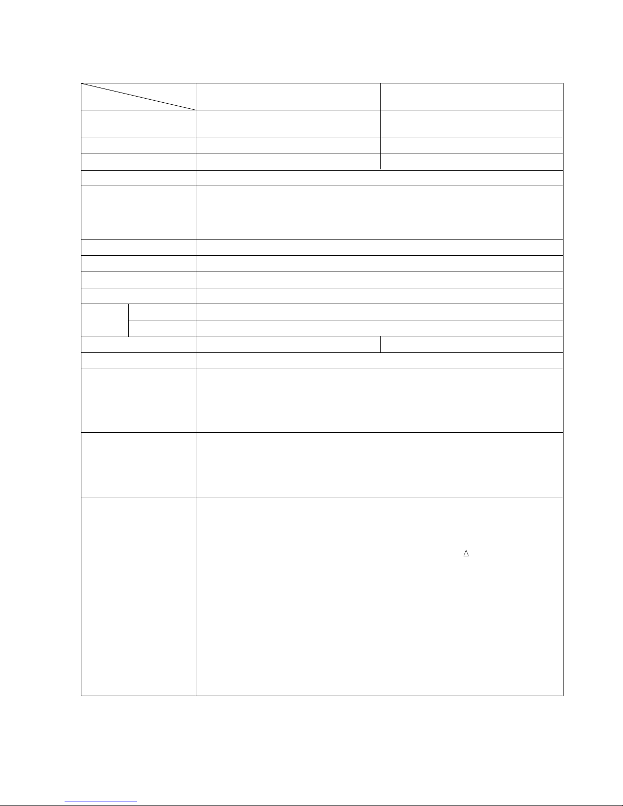
REMARK:
Throughout this TECHNICAL DATA AND SERVICE MANUAL, a symbol(s)
is(are) used in the place of company name(s) and model name(s) of our
competitor(s). The symbol(s) utilized here is(are) as follows:
Symbol Utilized
Competitor
Company Name
Model Name
C MAKITA
6908DWA
WH 8DH

Page
CONTENTS
[ Business Section ]
1. PRODUCT NAME
••••••••••••••••••••••••••••••••••••••••••••••••••••••••••••••••••••••••••••••••••••••••••••••••••••••••••••••••••••••
1
2. MARKETING OBJECTIVE
•••••••••••••••••••••••••••••••••••••••••••••••••••••••••••••••••••••••••••••••••••••••••••••••••••••••••
1
3. APPLICA TIONS
•••••••••••••••••••••••••••••••••••••••••••••••••••••••••••••••••••••••••••••••••••••••••••••••••••••••••••••••••••••••••
1
4. SELLING POINTS
••••••••••••••••••••••••••••••••••••••••••••••••••••••••••••••••••••••••••••••••••••••••••••••••••••••••••••••••••••••
2
4-1. Selling Point Descriptions
•••••••••••••••••••••••••••••••••••••••••••••••••••••••••••••••••••••••••••••••••••••••••••••••••••••
4
5. SPECIFICATIONS
••••••••••••••••••••••••••••••••••••••••••••••••••••••••••••••••••••••••••••••••••••••••••••••••••••••••••••••••••••••
5
5-1. Specifications
•••••••••••••••••••••••••••••••••••••••••••••••••••••••••••••••••••••••••••••••••••••••••••••••••••••••••••••••••••••••
5
5-2. Optional Accessories
••••••••••••••••••••••••••••••••••••••••••••••••••••••••••••••••••••••••••••••••••••••••••••••••••••••••••••
6
6. COMPARISONS WITH SIMILAR PRODUCTS
•••••••••••••••••••••••••••••••••••••••••••••••••••••••••••••••••••••••••••
10
6-1. Specification Comparisons (Cordless Impact Driver)
•••••••••••••••••••••••••••••••••••••••••••••••••••••••••••••••
10
6-2. Specification Comparisons (Cordless Impact Wrench)
••••••••••••••••••••••••••••••••••••••••••••••••••••••••••••
11
6-3. Tightening Torque
•••••••••••••••••••••••••••••••••••••••••••••••••••••••••••••••••••••••••••••••••••••••••••••••••••••••••••••••••
12
6-4 Tightening Speed
•••••••••••••••••••••••••••••••••••••••••••••••••••••••••••••••••••••••••••••••••••••••••••••••••••••••••••••••••••
16
6-5. Number of Screws or Bolts Driven
•••••••••••••••••••••••••••••••••••••••••••••••••••••••••••••••••••••••••••••••••••••••••
17
7. PRECAUTIONS IN SALES PROMOTION
••••••••••••••••••••••••••••••••••••••••••••••••••••••••••••••••••••••••••••••••••
19
7-1. Safety Instructions
••••••••••••••••••••••••••••••••••••••••••••••••••••••••••••••••••••••••••••••••••••••••••••••••••••••••••••••••
19
7-2. Tightening Torque Inspection Prior to Operation
••••••••••••••••••••••••••••••••••••••••••••••••••••••••••••••••••••••
21
7-3. Tightening Torque V ariation
•••••••••••••••••••••••••••••••••••••••••••••••••••••••••••••••••••••••••••••••••••••••••••••••••••
21
7-4. Suggestions and precautions for the Efficient Use of the Charger
••••••••••••••••••••••••••••••••••••••••••••
23
8. OTHER PRECAUTIONS
••••••••••••••••••••••••••••••••••••••••••••••••••••••••••••••••••••••••••••••••••••••••••••••••••••••••••••
24
[ Service section ]
9. REPAIR GUIDE
••••••••••••••••••••••••••••••••••••••••••••••••••••••••••••••••••••••••••••••••••••••••••••••••••••••••••••••••••••••••••
25
9-1. Precautions in Disassembly and Reassembly
•••••••••••••••••••••••••••••••••••••••••••••••••••••••••••••••••••••••••
25
9-2. Precautions in Disassembly and Reassembly of Battery Charger
•••••••••••••••••••••••••••••••••••••••••••••
30
11. STANDARD REPAIR TIME (UNIT) SCHEDULES
•••••••••••••••••••••••••••••••••••••••••••••••••••••••••••••••••••••
31
[ Appendix ]
Assembly Diagram for WH 8DH
•••••••••••••••••••••••••••••••••••••••••••••••••••••••••••••••••••••••••••••••••••••••••••••••••••
32
Assembly Diagram for WR 8DH
••••••••••••••••••••••••••••••••••••••••••••••••••••••••••••••••••••••••••••••••••••••••••••••••••
35

--- 1 ---
1. PRODUCT NAME
Hitachi Cordless Impact Driver, Model WH 8DH
Hitachi Cordless Impact Wrench, Model WR 8DH
2. MARKETING OBJECTIVE
The current Hitachi cordless impact driver series has provided excellent on-the-job performance thanks to their
design that produces no recoil force in tightening screws and bolts and also no damage to the screw heads.
The current DC 12V cordless impact driver Model WH 12DH and the cordless impact wrench Model WR 12DH
are well-reputed because they have better tightening performance and longer service life than previous models,
thanks to a replaceable carbon brush motor. Now, the new cordless impact driver Model WH 8DH is brought out
to respond to users' requests for a replaceable carbon brush motor for a DC 9.6 V product. The new cordless
impact wrench Model WR 8DH is also brought out. The Model WR 8DH has higher tightening torque than the
previous Model WH 8D2 and its square drive dimension is 12.7 mm (1/2") for use of commercially-available 1/2"
sockets. The construction of the Model WR 8DH is the same as that of the Model WH 8DH except the anvil (K)
assembly and the hammer case.
3. APPLICA TIONS
•
Tightening/loosening of small screws, tapping screws, wood screws, bolts, nuts, etc.
•
Drilling into wood and various other materials (with use of optional accessory drill chuck adapter).
[Applicable Markets]
•
Wood-product assembly: Tightening/loosening of wood screws, lag bolts, etc.
•
Construction industry: Assembly of scaffolding, roofing, aluminum sashes, fencing, etc.; removal of plastic cones
from concrete forms, mounting/removal of form ties; drilling into the wood frames of concrete forms, etc.
•
Manufacturing industry: Assembly work for automobiles, rolling stock, shipbuilding, agricultural machinery and
tools, industrial machines, steel furniture, etc.
•
Utility industry: Assembly and installation of electric equipment, plumbing facilities, air conditioning (duct
assembly, etc.), sanitary fixtures and various other facilities.
•
Service industry: General repair work; installation of advertising signs, automobile repair, assembly of garages
and carports storage sheds, etc.
•
Various other assembly, construction or repair facilities.
--- 2 ---
4. SELLING POINTS
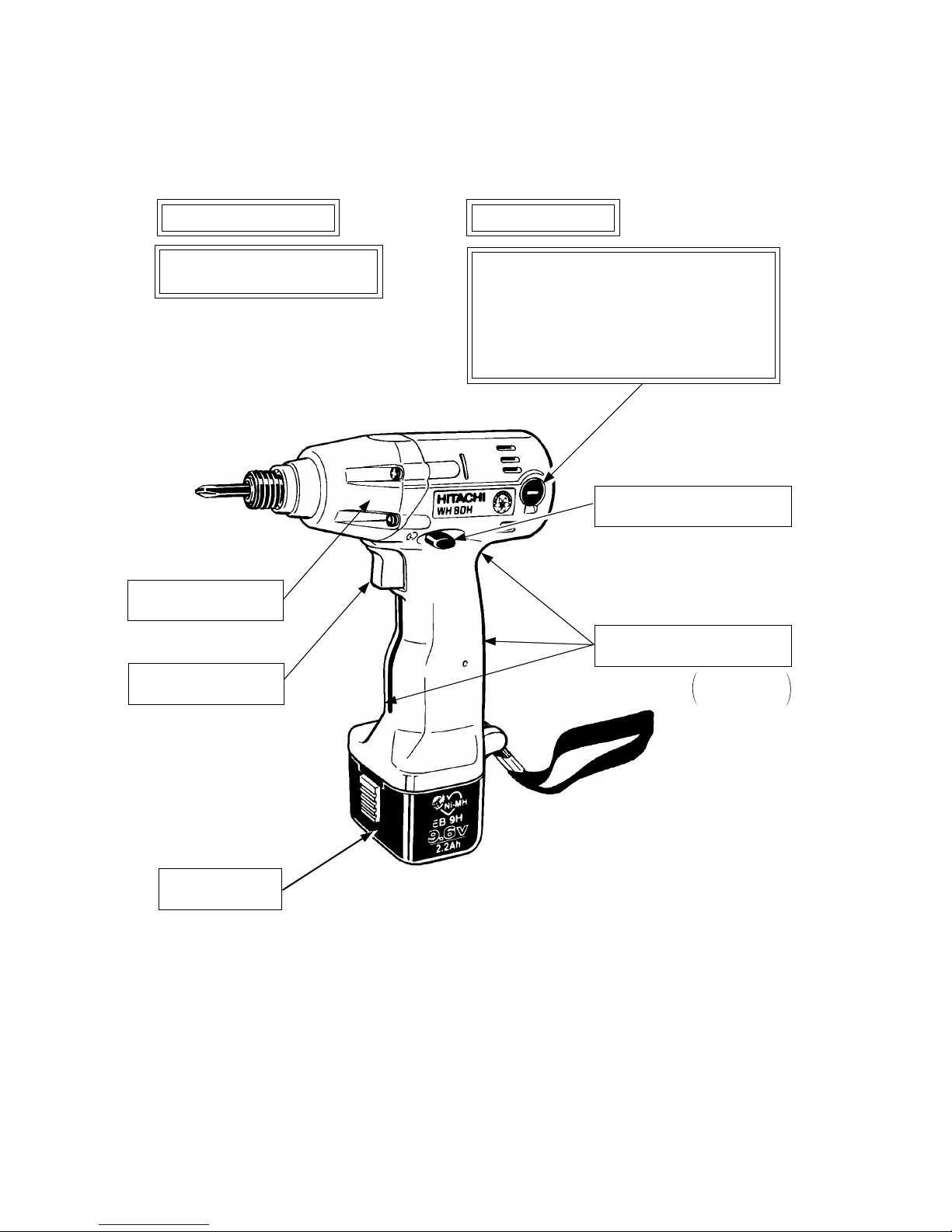
(1) Cordless Impact Driver: WH 8DH
Faster screw fastening
Higher fastening torque
88.2 N•m (900 kgf•cm, 65 ft-lbs)
Improved motor performance
•
Replaceable carbon brushes for longer
motor life
•
High-power fan-cooled DC magnet motor
•
Higher heat-resistance
•
The same torque and speed in both
forward and reverse modes
Longer service life
DC 9.6 V battery
EB 9B or EB 9H
Heavy-duty aluminum
hammer case
Variable speed switch
with electric brake
Easy-to-use forward/reverse
changeover pushing button
Ergonomically designed
handle for a comfortable grip
Grip inserts
front and rear
--- 3 ---
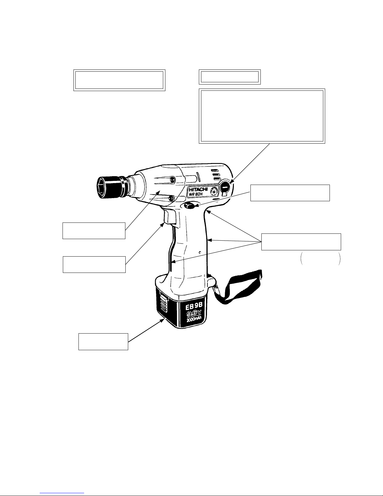
(2) Cordless Impact Wrench: WR 8DH
Higher fastening torque
98 N•m (1000 kgf•cm, 72 ft-lbs)
Improved motor performance
•
Replaceable carbon brushes for longer
motor life
•
High-power fan-cooled DC magnet motor
•
Higher heat-resistance
•
The same torque and speed in both
forward and reverse modes
Longer service life
DC 9.6 V battery
EB 9B or EB 9H
Heavy-duty aluminum
hammer case
Variable speed switch
with electric brake
Easy-to-use forward/reverse
changeover pushing button
Ergonomically designed
handle for a comfortable grip
[12.7 mm (1/2") Square drive]
Grip inserts
front and rear
--- 4 ---
4-1. Selling Point Descriptions
(1) Faster tightening speed
The Model WH 8DH provides faster driving speed than the previous model thanks to the high-power motor
and the higher moment of inertia of the hammer.
Tightening time comparison of the Model WH 8DH with the previous Model WH 8DA2 and maker C's model
are shown below. (Wood screw 4.2 mm dia. x 90 mm length, hemlock spruce)
HITACHI WH 8DH
HITACHI WH 8DA2
C
5.9 sec.
Model
510
sec.
6.5 sec.
6.8 sec.
(2) Improved motor performance
The Models WH 8DH and WR 8DH have high power thanks to the fan cooled DC magnet motor. They have
better heat-resistance because the built-in fan enhances cooling efficiency. Their motors have replaceable
carbon brushes, and the service life of the carbon brush has been extended by increasing its size by about 70
% (volume) compared to our previous model.
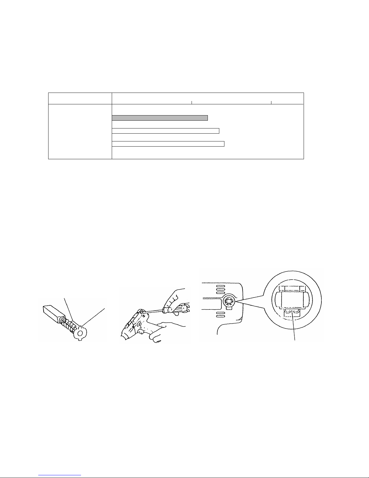
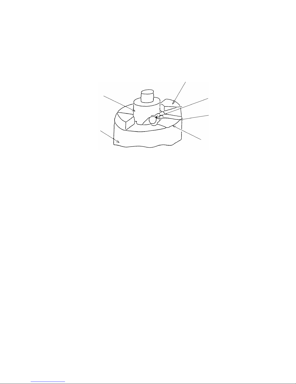
(3) Construction of replaceable carbon brushes
The carbon brush can be easily removed from the motor with a flat-blade screwdriver as shown in Fig. 2 and
can also be easily and securely mounted to the motor by hanging the claw of the carbon brush on the
connecting portion on the outside of the brush tube.
Claw of
carbon brush
Collar of
carbon brush
Connecting portion at the
outside of brush tube
Fig. 1 Fig. 2 Fig. 3
(4) Safe handle shape
Compared with the previous WH 8DA2, the housing of the Model WH 8DH produces no clearance caused by
vibration because front and rear grip inserts [part names: grip (R) and grip (F), made of rubber] are provided at
the juncture of the handle, and the housing is secured with two screws at the center of the handle to prevent
the operator's hand from being pinched. Furthermore, the rear portion of the housing is shaped upward so not
to interfere with the base of the operator's thumb.
--- 5 ---
5. SPECIFICATIONS
5-1. Specifications
Model
Cordless Impact Driver
WH 8DH
Capacity
Item
Cordless Impact Wrench
WR 8DH
Small screw M4 --- M8 (5/32" --- 5/16")*
1
Ordinary bolt M5 --- M12 (3/16" --- 15/32")
Ordinary bolt M6 --- M14 (1/4" --- 9/16")
High-strength bolt M6 --- M10 (1/4" --- 3/8")
Tightening torque
88.2 N•m (900 kgf•cm, 65 ft-lbs)*
2
98 N•m (1000 kgf•cm, 72 ft-lbs)
*
3
Tip condition
6.35 mm (1/4") Bit holder
12.7 mm (1/2") Square drive
Type of motor
Fan cooled DC magnet motor
Enclosure
Main body: Polyamide resin
••••••
Housing
Aluminum alloy die casting
••••••
Hammer case
Storage battery: ABS resign (black)
Charger: ABS resin (black)
Type of switch
Trigger switch with forward / reverse changeover pushing button (with brake and variable)
Handle configuration
T-type
No-load rotational speed
0 --- 2,200 /min
Impact rate
0 --- 2,900 /min
Main body
1.6 kg (3.5 lbs) (Includes battery)*
4
Battery
0.52 kg (1.1 lbs)
Overall length x height
176 mm (6-15/16") x 220 mm (8-21/32")
Center height
26 mm (1-1/64")
Battery (Type EB 9B)
Sealed cylindrical nickel-cadmium batteries
Nominal voltage: DC 9.6V
Nominal life: Charging/discharging approximately 1,000 cycles (in case of Model
UC 14YF2)
Nominal capacity: 2.0 Ah
180 mm (7-1/8") x 220 mm (8-21/32")
Battery (Type EB 9H)
Sealed cylindrical nickel-metal hydride batteries
Nominal voltage: DC 9.6V
Nominal life: Charging/discharging approximately 500 cycles (in case of Model
UC 14YF2)
Nominal capacity: 2.2 Ah
*1: In the case of tapping screws and wood screws, a minimum of M3 (1/8") is possible.
*
2
: This torque is based on tightening an M12 (15/32") bolt (strength grade: 12.9) for 3 seconds with a hexagonal socket.
*
3
: This torque is based on tightening an M12 (15/32") bolt (strength grade: 12.9) for 3 seconds with a hexagonal socket.
*
4
: Main body does not include accessory tools (hexagonal bit, etc.).
Charger (UC 14YF2)
Charger power source: single-phase AC, 50/60 Hz
Voltage: Depending on the order specification
Power input: 44 W
Charging system: Constant current charge with full wave phase control
Overcharge protection system: (1) Battery voltage detection ( 2V system)
(2) Battery surface temperature detection
(thermostat or thermistor)
(3) 120 minute timer
Output voltage: 7.2 V --- 14.4 V
Output current: 1.9 A
Charging time: Approx. 60 minutes (for B-type storage battery at 20 ˚C)
Approx. 70 minutes (for H-type storage battery at 20 ˚C)
Product weight: 1.3 kg
Operable ambient temperature range: 0 ˚C --- 40 ˚C
The maximum allowable temperature of the EB 9B type battery is 60 ˚C and the
EB 9H type battery is 45 ˚C.
Weight
--- 6 ---
Prior to charging
During charging
Charging completed
Charging not
possible
High battery
temperature
Blinks
Lit
Blinks
Flickers
Lit
0.5 sec ON, 0.5 sec OFF
Stays ON constantly
0.5 sec ON, 0.5 sec OFF
0.1 sec ON, 0.1 sec OFF
Stays ON constantly
Pilot lamp indications (UC 14YF2)
Red pilot lamp
remains lit of flashes
Green pilot lamp is lit
Storage battery or charger
is faulty.
Charging not possible
because storage battery
temperature is too high.
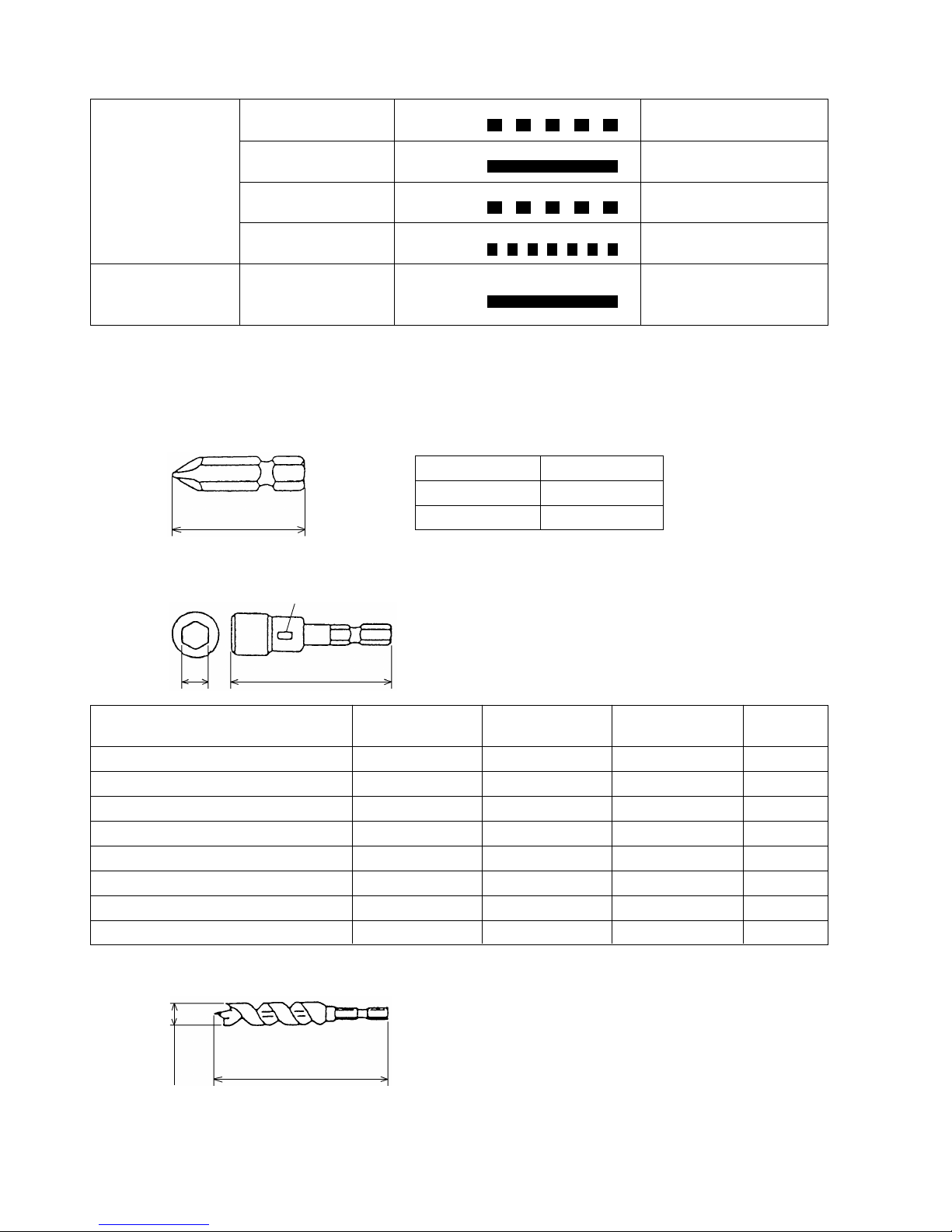
5-2. Optional Accessories
(1) Optional accessories for the Model WH 8DH
•
Plus driver bit
50 mm (2")
Bit No.
No. 2
No. 3
Code No.
992671
992672
•
Hexagon socket
L
B
Stamped figures
996177 8 (5/16")65 (2-9/16") 8
Stamped figures
5 mm Hexagon socket
Part Name
L
(mm)
B
(mm)
Code No.
98532910 (3/8")65 (2-9/16")106 mm Hexagon socket
99617812 (15/32")65 (2-9/16")125/16" Hexagon socket
99617913 (1/2")65 (2-9/16")138 mm Hexagon socket
99618014 (9/16")65 (2-9/16")1410 mm Hexagon socket (small type)
99618116 (5/8")65 (2-9/16")1610 mm Hexagon socket
99618217 (21/32")65 (2-9/16")1710 mm Hexagon socket
99619721 (53/64")166 (6-17/32")211/2" Hexagon long socket
•
Woodworking drill bit (Code No. 959183)
14 mm dia.
(35/64")
83 mm (3-17/64")
--- 7 ---
•
Drill chuck adaptor set (Code No. 996195)
The drill chuck adaptor set permits mounting of various types of locally-available drill bits for a variety of drilling
operations.
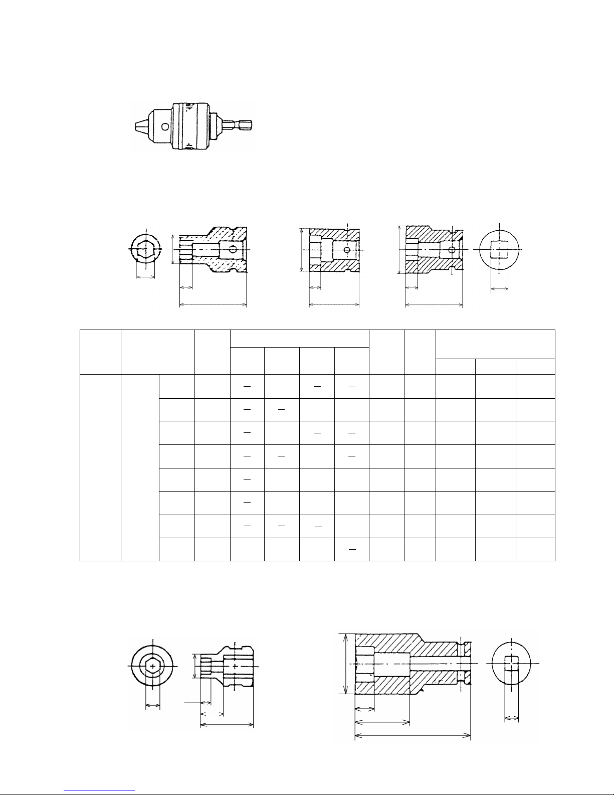
(2) Optional accessories for the Model WR 8DH
•
Each dimension and applicable bolt for each hexagon socket
Shape B
Shape C Shape D
H
D
1
L1
L
D
1
L1
L
D
1
L1
L
Sq
18
(23/32")
20
(25/32")
25
(1")
25
(1")
28
(1-3/32")
28
(1-3/32")
32
(1-1/4")
35
(1-3/8")
8
(5/16")
8
(5/16")
9
(11/32")
9
(11/32")
8
(5/16")
9
(11/32")
10
(3/8")
14
(9/16")
40
(1-9/16")
40
(1-9/16")
40
(1-9/16")
40
(1-9/16")
32
(1-1/4")
34
(1-11/32")
36
(1-13/32")
40
(1-9/16")
B
B
B
B
C
C
D
D
10
(3/8")
12
(15/32")
13
(1/2")
14
(9/16")
17
(21/32")
19
(23/32")
21
(53/64")
22
(7/8")
W 5/16"
W 3/8"
W 7/16"
W 1/2"
M 8
(5/16")
M 10
(3/8")
M 12
(15/32")
M 14
(9/16")
M 16
(5/8")
M 6
(1/4")
M 8
(5/16")
M 10
(3/8")
M 12
(15/32")
M 14
(9/16")
M 12
(15/32")
944291
873632
873539
873540
873536
873624
873626
873627
10 mm
12 mm
13 mm
14 mm
17 mm
19 mm
21 mm
22 mm
Hexagon
socket
12.7 mm
(1/2")
Square
drive
dimension
Sq
Part Name
Code No.
Nominal diameter of applicable bolts
Dihedral
width
H (mm)
Shape
Socket primary dimensions
(mm)
ISO
(high-strength)
ISO
(ordinary)
ISO
(small type)
Inch
screw L
L
1 D1
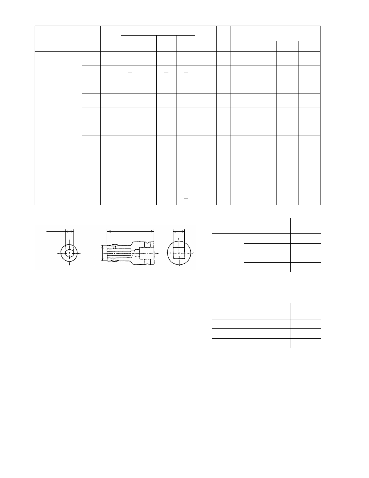
•
Each dimension and applicable bolt for each long socket
Shape B Shape D
H
D
1
(dia.)
L1
L
L1
L
Sq
L
2
D
1
(dia.)
L2
--- 8 ---
20
(25/32")
21.5
(53/64")
22
(7/8")
25
(1")
25
(1")
28
(1-3/32")
28
(1-3/32")
31
(1-7/32")
31
(1-7/32")
31
(1-7/32")
32.5
(1-9/32")
20
(25/32")
20
(25/32")
20
(25/32")
24
(15/16")
24
(15/16")
24
(15/16")
24
(15/16")
24
(15/16")
24
(15/16")
24
(15/16")
24
(15/16")
52
(2-3/64")
52
(2-3/64")
52
(2-3/64")
52
(2-3/64")
75
(2-15/16")
52
(2-3/64")
75
(2-15/16")
52
(2-3/64")
75
(2-15/16")
125
(2-15/16")
52
(2-3/64")
B
B
B
B
B
B
B
D
D
D
D
12
(15/32")
13
(1/2")
14
(9/16")
17
(21/32")
17
(21/32")
19
(23/32")
19
(23/32")
21
(53/64")
21
(53/64")
21
(53/64")
22
(7/8")
W 5/16"
W 3/8"
W 3/8"
W 7/16"
W 7/16"
W 1/2"
W 1/2"
W 1/2"
M 8
(5/16")
M 10
(3/8")
M 12
(15/32")
M 12
(15/32")
M 14
(9/16")
M 14
(9/16")
M 16
(5/8")
M 8
(5/16")
M 10
(3/8")
M 10
(3/8")
M 12
(15/32")
M 12
(15/32")
M 14
(9/16")
M 12
(15/32")
955138
955139
955140
955141
955149
955142
955150
955143
955151
991480
955144
12 mm
13 mm
14 mm
17 mm
17 mm
19 mm
19 mm
21 mm
21 mm
21 mm
22 mm
Long
socket
12.7 mm
(1/2")
Square
drive
dimension
Sq
Part Name
Code
No.
Nominal diameter of applicable bolts
Dihedral
width
H (mm)
Shape
Socket primary dimensions (mm)
ISO
(high-strength)
ISO
(ordinary)
ISO
(small type)
Inch
screw
L
L
1
D1
•
Bit adaptor (Code No. 991476)
6.35 mm (1/4")
45 mm (1-25/32")
13.5 mm dia.
(17/32")
12.7 mm (1/2")
34
(1-11/32")
34
(1-11/32")
34
(1-11/32")
34
(1-11/32")
57
(2-1/4")
34
(1-11/32")
57
(2-1/4")
34
(1-11/32")
57
(2-1/4")
107
(4-7/32")
34
(1-11/32")
L2
Part name
Overall length
(mm)
Code No.
Plus hd.
driver bit
No.2
Plus hds.
driver bit
No.3
45 (1-25/32") 955229
70 (2-3/4") 955654
45 (1-25/32") 955230
70 (2-3/4") 955655
•
Extension bar [Overall length 100 mm (3-15/16") ] (Code No. 873633)
•
Universal joint (Code No. 992610)
•
Socket ass'y for duct
••••••••••••••••••••••••••••••••••••••••••••••••••••••••••••••••••••
Dihedral width of
applicable bolts
Code No.
993658
13 (1/2") 992613
14 (9/16") 992615
12 (15/32")
•
EW-14R corner attachment (Code No. 9329-9001)
--- 9 ---
(3) Optional accessories for the Models WH 8DH and WR 8DH
•
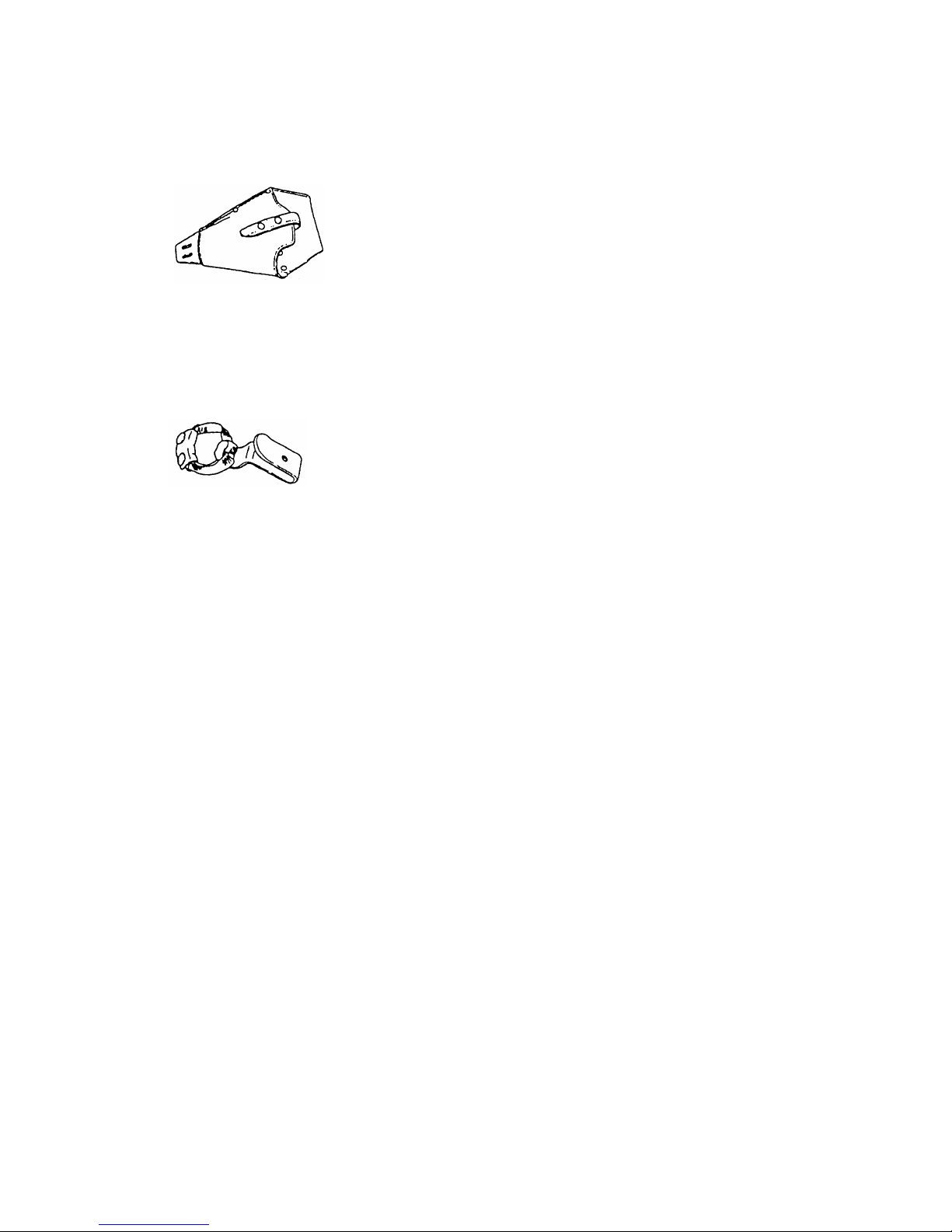
Holster (Code No. 307824)
Use the holster to hold the unit during its operation.
Carefully read the warnings attached to the holster for safe use.
•
Hook (Code No. 308090)
Use the hook to hold the unit during its operation.
Carefully read the instructions that come with the hook to learn how to use it.
--- 10 ---
6. COMPARISONS WITH SIMILAR PRODUCTS
6-1. Specification Comparisons (Cordless Impact Driver)
M 4 --- M 8
(5/32" --- 5/16")
HITACHI
WH 8DH WH 8DA2
C
Maker
Model
Item
M 5 --- M 8
(3/16" --- 5/16")
M 4 --- M 8
(5/32" --- 5/16")
Catalog specifications
Capacity
Small screw
M 5 --- M 12
(3/16" --- 15/32")
M 5 --- M 12
(3/16" --- 15/32")
M 5 --- M 12
(3/16" --- 15/32")
Ordinary bolt
M 5 --- M 10
(3/16" --- 3/8")
M 5 --- M 10
(3/16" --- 3/8")
M 5 --- M 10
(3/16" --- 3/8")
High-strength bolt
88.2
(900 kgf•cm, 65 ft-lbs)*
2
78.4
(800 kgf•cm, 58 ft-lbs)*
3
78.4
(800 kgf•cm, 58 ft-lbs)*
3
Max. tightening torque N•m
0 --- 2,200
2,200 0 --- 2,200No-load rotation speed
/min
0 --- 2,900
2,800 0 --- 2,800Impact rate
/min
1.6 (3.5 lbs) 1.4 (3.1 lbs) 1.4 (3.1 lbs)Main body weight
kg
91.1
(930 kgf•cm, 67.3 ft-lbs)*
2
83.8
(850 kgf•cm, 61 ft-lbs)*
3
85.8
(875 kgf•cm, 63.3 ft-lbs)*
3
Max. tightening torque
N•m
Measured figures
0 --- 2,230
2,150 0 --- 2,470No-load rotation speed
/min
0 --- 2,790
2,700 0 --- 2,680Impact rate
/min
176 x 220
(6-15/16" x 8-21/32")
175 x 218
(6-7/8" x 8-19/32")
Overall length x height
mm
171 x 232
(6-47/64" x 9-9/64")
26 (1-1/64")
26 (1-1/64") 26 (1-1/64")Center height
mm
1.6 (3.5 lbs)
1.47 (3.2 lbs) 1.5 (3.3 lbs)Main body weight
kg
67
66 68
No-load sound pressure level
dB(A)
Driver chuck
Driver chuck Driver chuck
Tool tip mounting system
Trigger switch with
forward / reverse
changeover pushing
button with brake and
variable
Type of switch
Trigger switch with
forward / reverse
changeover pushing
button with brake
Variable speed switch with
forward/reverse
changeover lever
DC magnet
DC magnet DC magnet
Type of motor
9.6
9.6 9.6
Voltage
20
20 20
Current
EB 9B or EB 9H
EB 9 9122
Battery
V
A
Type
EB 9B: 2.0
EB 9H: 2.2
1.3 2.0
Nominal capacity
Ah
9.6
9.6 9.6
Nominal voltage
V
0 --- 40
5 --- 40 ------
Ambient temperature
˚C
UC 14YF2
UC 12Y DC1411
Model
44
51 ------
Power input capacity
VA
7.2 --- 14.4
2.4 --- 12 7.2 --- 14.4
Recharging voltage
V
•
Plastic tool case
•
Charger (UC 14YF2)
•
Plastic tool case
•
Charger (UC 12Y)
•
Plastic tool case
•
Charger (DC1411)
Standard accessories
Charger
*1: In the case of tapping screws and wood screws, a minimum of M3 (1/8") is possible.
*
2
: Max. tightening torque is based on tightening an M12 (5/32") bolt (strength grade: 12.9) for 3 seconds with a hexagon
socket.
*3: Max. tightening torque is based on tightening an M10 (3/8") bolt (strength grade: 12.9) for 3 seconds with a hexagon socket.
*
4
: Main body weight does not include accessory tools (hexagon bit, etc.).
*
1
*
4
*
2
*
4
--- 11 ---
6-2. Specification Comparisons (Cordless Impact Wrench)
HITACHI
WR 8DH
Maker
Model
Item
Catalog specifications
Capacity
M 6 --- M 14
(1/4" --- 9/16")
Ordinary bolt
M 6 --- M 10
(1/4" --- 3/8")
High-strength bolt
98
(1,000 kgf•cm, 72 ft-lbs)
Max. tightening torque
N•m
0 --- 2,200
No-load rotation speed
/min
0 --- 2,900
Impact rate
/min
1.6 (3.5 lbs)
Main body weight
kg
100
(1,010 kgf•cm, 73.1 ft-lbs)
Max. tightening torque
N•m
Measured figures
0 --- 2,230
No-load rotation speed
/min
0 --- 2,790
Impact rate
/min
180 x 220
(7-1/8" x 8-21/32")
Overall length x height
mm
26 (1-1/64")
Center height
mm
1.6 (3.5 lbs)
Main body weight
kg
67
No-load sound pressure level
dB(A)
Pin/O-ring or plunger
Tool tip mounting system
Trigger switch with forward/reverse
changeover pushing button with
brake and variable
Type of switch
DC magnet
Type of motor
9.6
Voltage
20
Current
EB 9B or EB 9H
Battery
V
A
Type
EB 9B: 2.0
EB 9H: 2.2
Nominal capacity
Ah
9.6
Nominal voltage
V
0 --- 40
Ambient temperature
˚C
UC 14YF2
Model
44
Power input capacity
VA
7.2 --- 14.4
Recharging voltage
V
•
Plastic tool case
•
Charger (UC 14YF2)
Standard accessories
Charger
*1: Max. tightening torque is based on tightening an M12 (5/32") bolt (strength grade: 12.9) for 3 seconds with a hexagon
socket.
*2: Main body weight does not include accessory tools (hexagon bit, etc.).
*
1
*
2
*
1
*
2
WH 8D2
M 5 --- M 12
(3/16" --- 15/32")
M 5 --- M 10
(3/16" --- 3/8")
88.2
(900 kgf•cm, 65.1 ft-lbs)
2,200
2,800
1.4 (3.1 lbs)
93.1
(950 kgf•cm, 68.7 ft-lbs)
2,150
2,700
171 x 218
(6-23/32" x 8-19/32")
26 (1-1/64")
1.46 (3.2 lbs)
66
Pin/O-ring or plunger
Trigger switch with forward /
reverse changeover pushing button
with brake
DC magnet
9.6
20
EB 9
1.2
9.6
5 --- 40
UC 12Y
51
2.4 --- 12
•
Charger (UC 12Y)

--- 12 ---
6-3. Tightening Torque
6-3-1. Tightening Torque Characteristic Comparisons
The Model WH 8DH and WR 8DH provide greater tightening torque than the previous models thanks to the high
power motor and the higher moment of inertia of the hammer. The tightening torque does not drop even when
loosening bolts because the motor runs at the same torque and speed in both the forward and reverse directions.
Tightening torque comparisons of Models WH 8DH and WR 8DH with previous models are shown in Figs. 4-1 and
4-2. It should be noted that M12 (15/32") and M10 (3/8") strength grade 12.9 high-strength bolts were utilized in
the tests to ensure that the bolts were not stripped or distorted, even though such bolts are actually beyond the
recommended maximum capacity of these models. Accordingly, the data in the figures below are intended for
reference purposes only.
(1) Impact Driver
Fig. 4-1
Fig. 4-2
Test conditions
Bolt: M12 x 45 mm (15/32" x 1-3/4")
M10 x 30 (3/8" x 1-3/16")
(strength grade: 12.9)
Steel plate: Mild steel
M12 (15/32") Thickness = 25 mm (1")
M10 (3/8") Thickness = 10 mm (3/8")
Accessory tool: Hexagon socket ass'y
* An M10 x 30 high-strength bolts are tested unless
otherwise specified.
WH 8DH (M12 x 45)
WH 8DH*
WH 8DA2
200
(19.6 N
•
m,
14 ft-lbs)
0123
400
(39.2 N
•
m,
29 ft-lbs)
600
(58.8 N
•
m,
43 ft-lbs)
800
(78.4 N
•
m,
58 ft-lbs)
1000
(98 N
•
m,
72 ft-lbs)
(kgf•cm)
(sec.)
Tightening time
Tightening torque
C (forward)
[Tightening torque
in reverse rotation
is about 90 % of
that in forward
rotation.]
(2) Impact Wrench
WR 8DH
WH 8D2
200
(19.6 N
•
m,
14 ft-lbs)
0123
400
(39.2 N
•
m,
29 ft-lbs)
600
(58.8 N
•
m,
43 ft-lbs)
800
(78.4 N
•
m,
58 ft-lbs)
1000
(98 N
•
m,
72 ft-lbs)
(kgf•cm)
(sec.)
Tightening time
Tightening torque
Test conditions
Bolt: M12 x 45 mm (15/32" x 1-3/4")
(strength grade: 12.9)
Steel plate: Mild steel
M12 (15/32") Thickness = 25 mm (1")
Accessory tool: Hexagon socket ass'y

--- 13 ---
6-3-2. Screw Diameter and Appropriate Tightening Torque
Generally speaking, the appropriate tightening torque for a screw can be determined by the strength grade of the
screw and the material tightened. Tables 1 and 2, and Fig. 5 below list data relative to the strength grade of
various screws and the appropriate tightening torque. For further reference, appropriate tightening torque is
calculated with the following formula. Study and use this formula for accurate selection of tightening torque.
T=k•d•p
T: Appropriate tightening torque (kgf•cm)
k: Torque coefficient (0.17)
d: Nominal diameter for the screw (mm)
p: Recommended axial tightening force to be applied to the screw (kgf)
p=rated axial stress (kgf/cm2) x 0.8 x effective sectional area of the thread (mm2)
•
Strength grade and rated axial stress of threads
Strength grade
Rated axial stress (kgf/mm2)
Material
Heat treatment
4.8 6.8 8.8 12.9
29.1 43.7 58.2 95
Mild steel Alloy steel including Ni, Mn, Cr, etc.
None Processed-hard material
•
Diameter and effective sectional areas of threads
Kind of thread (x pitch)
Effective sectional area of
thread (mm2)
M5 x 0.8 mm
(3/16")
14.2
M6 x 1 mm
(1/4")
20.1
M8 x 1.25 mm
(5/16")
36.6
M10 x 1.5 mm
(3/18")
58.0
M12 x 1.75 mm
(15/32")
84.3
M14 x 2 mm
(9/16")
115
•
Thread diameter and appropriate tightening torque
Fig. 5
Strength grade 12.9
(high-strength bolt)
Strength grade 8.8
(high-strength bolt)
Strength grade 6.8
(ordinary bolt)
Strength grade 4.8
(ordinary bolt)
005
(3/16")6(1/4")
8
(5/16")
10
(3/8")
12
(15/32")
14
(9/16")
mm
200
(19.6 N•m, 14 ft-lbs)
400
(39.2 N
•
m, 29 ft-lbs)
600
(58.8 N
•
m, 43 ft-lbs)
800
(78.4 N•m, 58 ft-lbs)
1000
(98 N•m, 72 ft-lbs)
1200
(117.6 N
•
m, 86 ft-lbs)
(kgf•cm)
Thread diameter
Appropriate tightening torque
Table 1
Table 2

--- 14 ---
200
(19.6 N•m,14 ft-lbs)
0123
400
(39.2 N
•
m,29 ft-lbs)
600
(58.8 N
•
m,43 ft-lbs)
800
(78.4 N
•
m,58 ft-lbs)
1000
(98 N
•
m,72 ft-lbs)
(kgf•cm)
Tightening time
[steel plate thickness:
t=3/8" (10 mm)]
M8 x 30 mm
(5/16" x 1-3/6")
Tightening torque
High-strenge bolt
Ordinary bolt
200
(19.6 N•m,14 ft-lbs)
0123
400
(39.2 N
•
m,29 ft-lbs)
600
(58.8 N
•
m,43 ft-lbs)
800
(78.4 N
•
m,58 ft-lbs)
1000
(98 N
•
m,72 ft-lbs)
(kgf•cm)
Tightening time
[steel plate thickness:
t=3/8" (10 mm)]
M10 x 30 mm
(8/8" x 1-3/6")
Tightening torque
High-strenge bolt
Ordinary bolt
200
(19.6 N•m,14 ft-lbs)
0123
400
(39.2 N
•
m,29 ft-lbs)
600
(58.8 N
•
m,43 ft-lbs)
800
(78.4 N
•
m,58 ft-lbs)
1000
(98 N
•
m,72 ft-lbs)
1200
(117.6 N
•
m,86 ft-lbs)
(kgf•cm)
Tightening time
[steel plate thickness:
t=1" (25 mm)]
M12 x 45 mm
(15/32" x 1-3/4")
Tightening torque
High-strenge bolt
Ordinary bolt
(sec.)
(sec.)
(sec.)
6-3-3. Bolt Tightening Torque Characteristics
Figs. 6-1 and 6-2 show relationships between time and tightening torque for individual bolt types and sizes. While
the data are useful for handy reference, actual tightening torque will vary depending on tightening conditions and
other variables. For details, please refer to Para. 7-3, Tightening Torque Variation.
(Note)
•
The term "tightening time" indicates the impact time after the lower surface of the bolt has come in contact with
the material into which it is being tightened.
•
In the tightening conditions shown in Figs. 6-1 and 6-2, the screws are being tightened directly into a steel
plate; accordingly, the torque goes up very abruptly in comparison with ordinary bolt tightening conditions.
•
Model WH 8DH
Fig. 6-1
Bolt
Nut
Steel plate
thickness: t
* The following bolts were utilized:
Ordinary bolt; strength grade 4.8
High-strength bolt; strengh grade
12.9
Strength grade is read as follows:
4.8
Yield point or durable force:
(45,500 psi)
Tensile strength of the bolt:
(56,900 psi)

--- 15 ---
200
(19.6 N•m,14 ft-lbs)
0123
400
(39.2 N
•
m,29 ft-lbs)
600
(58.8 N•m,43 ft-lbs)
800
(78.4 N
•
m,58 ft-lbs)
1000
(98 N
•
m,72 ft-lbs)
1200
(117.6 N•m,86 ft-lbs)
(kgf•cm)
Tightening time
[steel plate thickness:
t=3/8" (10 mm)]
M8 x 30 mm
(5/16" x 1-3/6")
Tightening torque
High-strenge bolt
Ordinary bolt
200
(19.6 N•m,14 ft-lbs)
0123
400
(39.2 N
•
m,29 ft-lbs)
600
(58.8 N•m,43 ft-lbs)
800
(78.4 N
•
m,58 ft-lbs)
1000
(98 N
•
m,72 ft-lbs)
1200
(117.6 N•m,86 ft-lbs)
(kgf•cm)
Tightening time
[steel plate thickness:
t=1" (25 mm)]
M12 x 45 mm
(15/32" x 1-3/4")
Tightening torque
High-strenge bolt
Ordinary bolt
200
(19.6 N•m,14 ft-lbs)
0123
400
(39.2 N
•
m,29 ft-lbs)
600
(58.8 N•m,43 ft-lbs)
800
(78.4 N
•
m,58 ft-lbs)
1000
(98 N
•
m,72 ft-lbs)
1200
(117.6 N•m,86 ft-lbs)
(kgf•cm)
Tightening time
[steel plate thickness:
t=3/8" (10 mm)]
M10 x 30 mm
(8/8" x 1-3/6")
Tightening torque
High-strenge bolt
Ordinary bolt
(sec.)
(sec.)
(sec.)
•
Model WR 8DH
Fig. 6-2

--- 16 ---
6-4. Tightening Speed
Tightening speed comparisons of the Model WH 8DH with the previous Model WH 8DA2 and maker C's model
are shown below. The data shown below are intended for reference purposes only because actual tightening
speed will vary depending on the tightening conditions such as ambient temperature, charging capacity and
workpieces.
1 Tightening time (sec.) (Wood screw 4.2 mm dia. x 90 mm length, hemlock spruce)
HITACHI WH 8DH
HITACHI WH 8DA2
C
5.9 sec.
Model
510
sec.
6.5 sec.
6.8 sec.
HITACHI WH 8DH
HITACHI WH 8DA2
C
3.0 sec.
Model
1
sec.
3.3 sec.
3.5 sec.
2 3 4 5
HITACHI WH 8DH
HITACHI WH 8DA2
C
3.2 sec.
Model
1
sec.
3.5 sec.
3.8 sec.
2 3 4 5
HITACHI WH 8DH
HITACHI WH 8DA2
C
6.9 sec.
Model
510
sec.
8.5 sec.
8.7 sec.
2 Tightening time (sec.) (Wood screw 4.2 mm dia. x 75 mm length, soft wood)
3 Tightening time (sec.) (Wood screw 4.2 mm dia. x 90 mm length, soft wood)
4 Tightening time (sec.) (Wood screw 5.5 mm dia. x 120 mm length, soft wood)

--- 17 ---
5 Tightening time (sec.) (Teks screw 4 mm dia. x 13 mm length, SPCC 1.6 t )
6 Tightening time (sec.) (Wood screw 3.8 mm dia. x 20 mm length, lauan)
HITACHI WH 8DH
HITACHI WH 8DA2
C
2.5 sec.
Model
1
sec.
3.0 sec.
3.0 sec.
2 3 4 5
HITACHI WH 8DH
HITACHI WH 8DA2
C
1.2 sec.
Model
12
sec.
1.3 sec.
1.2 sec.
6-5. Number of Screws or Bolts Driven
6-5-1. Per-Charge Working Capacity Comparisons
Test data on the number of screws or bolts which can be driven per battery charge by the new models vs. the
previous models are shown in the tables below. Please note that the data below are intended for general
reference only as the number of screws which can be tightened per charge will vary slightly depending on screw
tightening conditions, screw sizes, ambient temperatures and the charging capacity of the battery.
(1) Number of screws or bolts driven (Cordless impact driver)
Battery
Tightening condition
Model
HITACHI
WH 8DH
HITACHI
WH 8DA2
C
EB 9B EB 9B
9122
(Corresponding EB 9B)
Wood screw 3.8 mm dia. x 20 mm
(soft wood)
430 460
450
Wood screw 4.0 mm dia. x 50 mm
(soft wood)
300 300
290
Wood screw 4.2 mm dia. x 75 mm
(soft wood)
220 220
210
Machine screw M8 x 16 mm
1,120 1,120
950
Teks screw 4.0 mm dia. x 13 mm
Mild steel plate t=1.6
170 170
160

--- 18 ---
6-5-2. Tightening Time and Number of Screws Driven Per Battery Charge
Fig. 7 Tightening time and number of
screws tightened
EB 9B
Tightening time
Number of screws tightened
0
100
200
300
400
500
600
700
800
(pcs.)
(sec.)
012345
Fig. 7 shows the relationship between the
tightening time and the number of screws which
can be tightened in a single battery charge in the
case of the EB 9B. (Tightening time is defined as
the period of time elapsed from the
commencement of the screw tightening operation
to the completion. As it can be seen, when the
tightening time is prolonged, the number of screws
which can be tightened per charge is decreased.)
Please note that the left data are intended for
general reference only, as the number of screws
which can be tightened per charge will vary slightly
depending on screw tightening conditions, screw
sizes, ambient temperatures and the charging
capacity of the battery.
(2) Ordinary bolt (Cordless impact wrench)
Battery
Tightening condition
Model
HITACHI
WR 8DH
HITACHI
WH 8D2
EB 9B
M8
ordinary bolt
880
0.4
Number of bolts
Time (sec.)
M10
ordinary bolt
430
0.8
Number of bolts
Time (sec.)
M12
ordinary bolt
220
1.5
Number of bolts
Time (sec.)
EB 9B
880
0.4
430
0.8
220
1.5

--- 19 ---
7. PRECAUTIONS IN SALES PROMOTION
7-1. Safety Instructions
In the interest of promoting the safest and most efficient use of these tools by all our customers, it is very
important that at the time of sale the salesperson carefully ensures that the buyer seriously recognizes the
importance of the contents of the Handling Instructions, and fully understands the meaning of the precautions
listed on the Caution Plate and Name Plate attached to each tool.
A. Handling Instructions
Salespersons must be thoroughly familiar with the contents of the Handling Instructions in order to give pertinent
advice to the customer. In particular, they must have a thorough understanding of the precautions in the use of
the cordless (battery charger type) electric power tools which are different from those of ordinary electric power
tools
(1) Before use, ensure that the unit is fully charged.
New units are not fully charged. Even if the units were fully charged at the factory, long periods without use,
such as during shipping, cause the storage battery to lose its charge. Customers must be instructed to fully
charge the unit prior to use.
(2) When charging storage batteries, use only the exclusive Model UC 14YF2 Charger provided with the tool.
Because of the designed rapid-charging feature (about one hour), use of other battery chargers is hazardous.
(3) Follow prescribed steps in using the charger.
First connect the EB 9B or EB 9H Storage Battery to the Model UC 14YF2 Charger, then plug the charger into
an AC outlet (ensuring that the voltage matches that indicated on the unit). If this order is reversed, the
charger may not function properly.
(4) Ensure the power source voltage is the same as that indicated on the Name Plate of the charger. Use of any
other power source (DC outlet, fuel powered generator, etc.) will cause the charger to overheat and burn out.
(5) Do not use any voltage increasing equipment (transformer, etc.) between the power source and the charger.
If the charger is used with voltage over and above that indicated on the unit, it will not function properly.
(6) Conduct battery charging at an ambient temperature range of 0 ˚C --- 40 ˚C (32 ˚F - -- 104 ˚F).
Special temperature sensitive devices are employed in the charger to permit rapid charging. Ensure that
customers are instructed to use the charger at the indicated ambient temperature range. At temperatures
under 0 ˚C (32 ˚F), the thermostat will not function properly, and the storage battery may be over-charged.
At temperatures over 40 ˚C (104 ˚F), the storage battery cannot be sufficiently charged. The optimum
temperature range is 20 ˚C --- 25 ˚C (68 ˚F --- 77 ˚F).
(7) The battery charger should not be used continuously.
At high ambient temperatures, if over three storage batteries are charged in succession, the temperature of
the coils on the transformer will rise and there is a chance that the temperature fuse inserted in the interior of
the transformer will inadvertently melt. After charging one battery, please charge the next battery after about a
fifteen-minute interval.
(8) The charger case is equipped with air vents to protect the internal electronic components from overheating.
Caution the customer not to allow foreign materials, such as metallic or flammable objects, to be dropped or
inserted into the air vents. This could cause electric shock, fire or other serious hazards.

--- 20 ---
CAUTION
•
Read thoroughly HANDLING INSTRUCTIONS
before use.
(9) Do not attempt to disassemble the storage battery or the charger.
Special devices, such as a thermostat, are built into the storage battery and charger to permit rapid charging.
Incorrect parts replacement and/or wiring will cause malfunctions which could result in fire or other hazards.
Instruct the customer to bring these units to an authorized service center in the event repair or replacement is
necessary.
(10) Disposal of the Type EB 9B or EB 9H Storage Battery
Ensure that all customers understand that Type EB 9B or EB 9H Storage Batteries should be turned into any
Hitachi power tool sales outlet or authorized service center when they are no longer capable of being
recharged or repaired. If thrown into a fire, the batteries may explode, or if discarded indiscriminately, leakage
of the cadmium compound contained in the battery may cause environmental pollution.
B. Caution Plates
(1) The following precautions are listed on the Name Plate attached to the main body of each tool.
For Europe
ACHTUNG
•
Lesen Sie die Bedienungsanleitung sorgfältig.
For Germany, Switzerland and Austria
TRES IMPORTANT
•
Lire avec attention la notice d'utilisation.
For France
Warning
•
To reduce the risk of injury, user must read and
understand Instruction Manual.
AVERTISSEMENT
•
Afin de réduire le risque de blessures, I'utilisateur doit lire
et bien comprendre le mode d'emploi.
For the U.S.A. (excludes French) or Canada
ATTENZIoNE
•
Leggere attentamente le istruzioni prima dell' uso.
For Itary

--- 21 ---
CAUTION
•
Read thoroughly HANDLING INSTRUCTIONS
before use.
•
Do not disassemble nor throw into fire.
(2) The following cautions are listed on the Name Plate attached to each Type EB 9B or EB 9H Storage Battery
For Europe
CAUTION
•
For safe operation, see Instruction Manual.
For the U.S.A.
CAUTION
•
For safe operation, see Instruction Manual.
•
Charge HITACHI rechargeable batteries Type EB 7, EB 9,
EB 12 and EB 14 series. Other types of batteries may burst
causing personal injury and damage.
•
Charge between 32 and 104 ˚F.
•
Indoor use only.
•
Replace defective cord immediately.
(3) The following caution is listed on the Name Plate attached to the Model UC 14YF2 Charger.
For the U.S.A.
7-2. Tightening Torque Inspection Prior to Operation
As described and shown in Para. 6-3-3, the output tightening torque of which the Models WH 8DH and
WR 8DH are capable in excess of the rated tightening torque of certain bolts and screws. Accordingly, if the
tightening time is prolonged for such bolts and screws, it could cause damage to their threads or, in the worst
case, cause them to be sheared off. (This phenomenon is common to all existing impact drivers.) Particularly
when tightening M6 (1/4") or smaller screws, tightening time must be kept extremely short: 0.5 seconds or less.
The customer should be advised to carry out several screw tightening operations and adjust the tightening time as
necessary by measuring the tightening torque with an appropriate torque wrench or driver before commencing
continuous operation
7-3. Tightening Torque Variation
The tightening torque of the cordless impact driver or wrench may vary slightly in accordance with the factors
described below. Salespersons are requested to advise the customer to confirm that appropriate tightening
torque is obtained by measuring the torque with an appropriate torque wrench or torque driver at the beginning of
the tightening operations, and as necessary during the tightening operations. In addition, the torque values
shown in Para. 6-3-2 above are useful as a handy reference, and may be utilized as tentative standards.

--- 22 ---
(1) Voltage of battery
Tightening torque is affected by the voltage output of the battery. For example, the relationship between
tightening torque and the number of M12 x 45 mm (15/32" x 1-3/4") high-strength bolts tightened is shown in
Fig. 8 below. As can be seen in the graph, tightening torque decreases as the number of bolts tightened
increases. This phenomenon is caused by the decline in voltage output of the battery due to the increasing
number of bolts tightened. In particular, the tightening torque decreases rapidly just before the battery is fully
discharged (range "a" in the graph). As this phenomenon is an inherent drawback in any cordless impact
driver, salespersons are requested to ensure that the customer is fully aware of and understands this
characteristic.
Model WR 8DH
Fig. 8
(2) Effects of low ambient temperatures
The tightening torque required may be reduced at low ambient temperatures or under the influence of grease
and different torque coefficients (dependent on manufacturing and finishing processes, and specified by bolt
manufacturers).
(3) Different bolt diameter
Differences in bolt diameter will cause variation of the required levels of tightening torque. Generally speaking,
tightening torque is higher for large bolts.
(4) Different materials being tightened
When a bolt is tightened into a soft material such as aluminum, plastic, wood, etc., the tightening torque is
considerably less than when the bolt is tightened into a hard material such as steel.
(5) Different tightening conditions
The tightening torque may vary in accordance with bolt torque coefficient (dependent on manufacturing
process, and specified by bolt manufactures), bolt grade and bolt length, even though the dimensions of the
bolts are the same. Tightening torque may also vary depending on the surface finishing state of tightening
materials (steel, aluminum, etc.), and materials to be tightened. In addition, if there is seal packing, clearance,
etc., between tightening materials, the tightening torque is decreased.
Fully charged
a
Battery voltage
Tightening torque
M12 x 45 mm (15/32" x 1-3/4") high-strength bolt (tightening time: 3 seconds)
400
(39.2 N•m, 29 ft-lbs)
800
(78.4 N•m, 58 ft-lbs)
1,200
(117.6 N•m, 86 ft-lbs)
0
2
4
6
8
10
20 40 60 80 100 120
Number of screws driven per charge (EB 9B battery)
Tightening torque
Battery voltage
(pcs.)
(kgf•cm)
(V)

--- 23 ---
(6) Wear and looseness of the socket
With extended use, the hexagonal portion of the socket which is fitted to the head of the bolt or drill bit, and/or
hexagonal portion of the driver chuck which is fitted onto the anvil in the main body will become worn and
loose. Wear and looseness will cause a proportionate loss of tightening torque.
In addition, use of an incorrect size socket (slightly larger than the bolt being tightened) will also result in
decreased torque.
(7) Bolt and nut rotate together
Tightening torque that can be achieved will be considerably decreased if the bolt and nut rotate together
during the tightening operation. The customer should be advised to carefully observe the operation and
ensure this does not occur.
7-4. Suggestions and precautions for the Efficient Use of the Charger
(1) Batteries may not be rechargeable immediately after use
If the Type EB 9B or EB 9H Storage Batteries are exposed to direct sunshine for an extended period, or if the
temperature of the batteries is 40 ˚C (104 ˚F) or higher immediately after they have been used in the tool, the
pilot lamp may not light up when the batteries are connected to the Model UC 14YF2 Charger. This is
because the built-in thermostat functions to stop the charging when the temperature of the storage batteries
reach 40 ˚C (104 ˚F) or more. In such a case, the customer should be advised to place the batteries in a
shaded area with a good airflow, and allow sufficient cooling before recharging.
This phenomenon is common to all existing batteries which employ temperature sensitive overcharge devices.
The cooling time required before charging can be accomplished varies from a few minutes to about 30
minutes, depending on the load, duration of use, and ambient temperatures.

--- 24 ---
8. OTHER PRECAUTIONS
(1) Check for cracks or other damage on the socket
Cracks or any other faults on the socket are very hazardous. In addition, cracks or other damage to
accessories will cause loss of tightening torque efficiency. Advise the customer to inspect accessories often,
and ensure there are no abnormalities.
(2) Socket dimensions
Without fail, utilize an appropriate socket which matches the bolt and/or nut dimensions. If the socket
dimensions are larger than the bolts or nuts, it will not only cause insufficient tightening torque, but could also
easily cause damage to the socket. Please refer to the tables in Para. 5-2 for appropriate socket dimensions.
(3) Hammering section lubrication
Grease (ATTOLUB MS No. 2) is utilized in the hammering section. Frequent or continuous use of the tool will
cause excessive temperature rise of the hammering section, resulting in depletion of the grease and
subsequent increased wear of components which will, in turn, cause loss of tightening efficiency. Accordingly,
it is necessary to periodically replenish the grease in the hammering section to ensure proper lubrication of
moving and sliding components.
(4) Vent holes in the handle
Do not stop up or cover the holes on either face of the handle. They are essential for ventilation.

--- 25 ---
9. REPAIR GUIDE
WARNING: Without fail, remove the Model EB 9B or EB 9H Battery from the main body before starting
repair or maintenance work. Because the tool is cordless, if the battery is left in and the
switch is activated inadvertently, the motor will start rotating unexpectedly, which could
cause serious injury.
9-1. Precautions in Disassembly and Reassembly
The [bold] and <bold> numbers correspond to the item numbers in the Parts List and the exploded assembly
diagram. ( [ ]: WH 8DH, < >: WR 8DH )
9-1-1. Disassembly
(1) Removal of the Hammer Case [6] <2> and the Inner Cover [21] <19>
Remove the four Tapping Screws D4 x 30 [5] <1> that connect the Hammer Case [6] <2> with the Housing
(A).(B) Set [28] <26>. Remove the Hammer Case [6] <2>, the Inner Cover [21] <19> and the Damper [22]
<20> together from the Housing (A).(B) Set [28] <26>.
(2) Removal of Housing (B)
Remove the seven Tapping Screws D4 x 20 [26] <24> from the main body to remove Housing (B).
(3) Remove the DC-Speed Control Switch [30] <28>, Fin Ass'y [32] <30>, Motor [23] [21], Grip (F) [33] <31> and
Grip (R) [37] <35> together. Remove the Pushing Button [31] <29> and the Strap [35] <33>.
(4) Disassembly of the switch ass'y
Remove the two Machine Screws M3 x 5 [29] <27> that secure the flag terminal and then disconnect the
internal wires (purple and black) of the Motor [23] <21> from the DC-Speed Control Switch [30] <28>.
Remove the S-Tight Screw D3.5 x 6 [36] <34> to remove the Fin Ass'y [32] <30> from the FET of the DCSpeed Control Switch .
(Note) Do not disconnect the three FET internal wires soldered to the DC-Speed Control Switch.
(5) Removal of the Guide Sleeve [4] (for WH 8DH only)
By following the procedure shown in Figs. 9-1 to 9-4, you can remove the Retaining Ring [1], Washer (D) [2],
Guide Spring [3] and Guide Sleeve [4] in this order. Be sure not to lose the Steel Ball D3.5 [7] in Anvil (B) [8].

--- 26 ---
Anvil (B) [8]
Retaining
Ring [1]
Washer (D) [2]
Guide Sleeve [4]
Gap of retaining ring
1
Fig. 9-1
Hold the body and adjust gap of the retaining ring to
groove of anvil (B), then insert a small flat-blade
screwdriver into the groove at an angle.
2
Fig. 9-2
Press down washer (D) with the screwdriver.
3
Fig. 9-3
Slide the screwdriver under one side of the gap of
the retaining ring.
4
Fig. 9-4
Slowly raise the retaining ring using the end face of
the guide sleeve as a fulcrum.
Then slowly raise the other side of the retaining ring with the screwdriver until it is free. The Guide Sleeve [4] can
not be removed. Avoid quickly raising the retaining ring or it may fly out forcefully.
The retaining ring can also be easily removed by widening the gap of the retaining ring with the jig for retaining
ring and slowly raising the retaining ring with a small flat-blade screwdriver.
(6) Disassembly of the hammer assembly
Hammer [10] <7>
Push down.
Spindle [15] <13>
Spring [12] <10>
Stopper [14] <12>
Washer (S) [13] <11>
J-297 Base for washer (S)
Fig. 10
Mount the hammer assembly onto the
J-297 base for washer (S). With a
hand press, push down the top of the
Spindle [15] <13> to compress the
Spring [12] <10>. In this position,
remove the Stopper [14] <12> with a
flat-blade screwdriver, then release
the hand press. (See Fig. 10.)
Small flat-blade
screwdriver
--- 27 ---
Remove the hammer assembly from the J-297 base for washer (S) and support the end surface of the Spindle
[15] <13>. With a hand press, push down either of the raised faces of the Hammer [10] <7> to compress the
Spring [12] <10>. In this position, extract the two Steel Balls D5.556 [9] <6> from the cam grooves of the
Spindle [15] <13> and the Hammer [10] <7> with a small flat-blade screwdriver or a similar tool. Then, slowly
release the hand press and lift the Hammer [10] <7> and Washer (S) [13] <11> together to extract them from
the Spindle [15] <13>. The Spring [12] <10> can then be removed.
Steel ball
guide groove
Spindle [15] <13>
Hammer [10] <7>
Raised faces
of hammer
Top of spindle cam
Steel Ball [9] <6>
Fig. 11
9-1-2. Reassembly
Reassembly can be accomplished by following the disassembly procedures in reverse. However, special
attention should be given to the following items.
(1) Reassembly of Housing (A) assembly
(a) Be sure to follow the wiring diagram (Fig. 12-1) for proper wiring.
(b) When connecting the internal wires of the Motor [23] <21> to the DC-Speed Control Switch [30] <28>,
tightly fasten them with the Machine Screw M3 x 5 [29] <27> paying close attention to the direction of the
flag terminal (Fig. 12-2).
(c) Mount the Motor [23] <21> into Housing (A) so that the Brush Caps [25] <23> of the Motor [23] <21> and
the rib for preventing motor body from rotating fit in Housing (A).
(Note) Make sure that the internal wire (purple) is passed under the Motor so that it is not caught between
the Motor and Housing (A).
(d) Mount the DC-Speed Control Switch [30] <28> to Housing (A) so that the projection of the forwarding/
reversing lever at the top of the Switch is inserted into the U-shaped groove of the Pushing Button [31]
<29>. Secure the Fin Ass'y [32] <30> to the FET of the DC-Speed Control Switch [30] <28> with the S-
Tight Screw D3.5 x 6 [36] <34>.
(Note) Make sure that the three internal wires from the FET are passed above the DC-Speed Control
Switch [30] <28>.
(2) Reassembly of the Housing (A).(B) Set [28] <26>
Mount the Strap [35] <33>, Grip (F) [33] <31>, Grip (R) [37] <35> and Housing (B) to Housing (A), and secure
them with the seven Tapping Screws D4 x 20 [26] <24>.

--- 28 ---
Fig. 12-1
Fig. 12-2
Internal wire (purple)
Motor
Pinion
(Black)
(Purple)
Fin Ass'y [32] <30>
FET
S-Tight Screw D3.5 x 6
[36] <34>
Flag terminal
Machine screw M3 x 5
[29] <27>
DC-Speed Control Switch [30] <28>
Projection of forward/
reverse lever
Internal wire (black)
Schematic diagram viewed from A

--- 29 ---
(3) Reassembly of the hammer assembly
(a) Put Washer (S) [13] <11> onto the shaft of the Spindle [15] <13> and mount the Hammer [10] <7>
containing the twenty-five Steel Balls D3.5 [7] <8>, Washer (J) [11] <9> and the Spring [12] <10> to the
Spindle [15] <13>.
(b) Align the top of the cam groove on the Spindle [15] <13> with the steel ball guide groove on the Hammer
[10] <7> as illustrated in Fig. 11. Press down either of the raised faces of the Hammer [10] <7> with a
hand press to compress the Spring [12] <10> until the end surface of the Hammer contacts the flange of
the Spindle [15] <13>.
(c) Insert the two Steel Balls D5.556 [9] <6> into the steel ball guide groove. Check that the Steel Balls are
properly inserted in the cam groove. Then release the hand press.
(d) Mount the hammer assembly onto the J-297 base for washer (S). With a hand press, push down the top of
the Spindle [15] <13> to compress the Spring [12] <10>. On this condition, mount the Stopper [14] <12>
onto the spindle shaft and then release the hand press.
(e) Mount the Ring Gear [18] <16>, Ball Bearing [20] <18>, Inner Cover [21] <19> and Damper [22] <20> to
the above reassembly. Furthermore, mount the other mechanical parts and Anvil (B) [8] or Anvil (K) Ass'y
<4>, then the Hammer Case [6] <2>. When mounting Anvil (B) [8], use the J-296 anvil cap
(Fig. 13).
(Note) The oil seal may be turned inside out if the anvil cap is not used.
(4) Mounting the assembly from the Hammer Case [6] <2> to the Inner Cover [21] <19> to the housing assembly
Push the assembly from the Hammer Case [6] <2> to the Inner Cover [21] <19> into the housing assembly by
turning them clockwise and counterclockwise. Check that the Anvil can be easily turned. (If it cannot be
turned, check for correct mesh of the gears.) Secure the above assembly with the four Tapping Screws D4 x
30 [5] <1>.
(5) Reassembly of the Guide Sleeve [4] (for WH 8DH only)
Insert the Steel Ball D3.5 [7] into the hole of Anvil (B) [8]. Mount the Guide Sleeve [4], the Guide Spring [3]
and Washer (D) [2] in sequence. Mount the Retaining Ring [1] into the groove of Anvil (B) using the J-295 jigs
(A) and (B) for retaining ring as illustrated in Fig. 14.
J-296 anvil cap
Anvil (B) [8]
Push down.
Retaining
Ring [1]
Washer (D) [2]
J-295 jig (B) for retaining ring
J-295 jig (A) for retaining ring
Fig. 13 Fig. 14

--- 30 ---
(6) Check whether the direction of rotation of Anvil (B) [8] or Anvil (K) Ass'y <4> coincides with the directional
markings on the push-on side of the Pushing Button [31] <29>. When the Pushing Button [31] <29> is turned
to the (R) side, the direction of rotation of Anvil (B) [8] or Anvil (K) Ass'y <4> should be clockwise, as viewed
from behind.
(7) Lubrication
(a) ATTOLUB MS No. 2
•
Cam groove of the Spindle [15] <13>
•
Cam groove of the Hammer [10] <7>
•
Sliding section of the Hammer and the Spindle
•
8 mm Diameter hole of Anvil (B) [8] or Anvil (K) Ass'y [4]
•
Sliding section between Anvil (B) [8] or Anvil (K) Ass'y [4] and the metal
•
Two Steel Balls D5.556 [9] <6>
•
Pinion tooth flanks of the Motor [23] <21>
•
Tooth flanks of the Ring Gear [18] <16>
•
Twenty-five Steel Balls D3.5 [7] <8>
(b) HITACHI MOTOR GREASE No. 29 (for WH 8DH only)
•
Steel Ball D3.5 [7]
•
Sliding section of Anvil (B) [8] and the Guide Sleeve [4]
(8) Screw tightening torque
•
Tapping Screw (with sp. washer) D4 x 30
••••••••••••••••••••
20 5 kgf•cm (1.96 0.49 N•m, 1.44 0.36 ft-lbs)
•
Tapping Screw (with flange) D4 x 20
•••••••••••••••••••••••••••
20 5 kgf•cm (1.96 0.49 N•m, 1.44 0.36 ft-lbs)
•
S-Tight Screw D3.5 x 6
••••••••••••••••••••••••••••••••••••••••••••••
15 --- 20 kgf•cm (1.96 --- 2.61 N•m, 1.44 --- 1.92 ft-lbs)
•
Machine Screw M3 x 5
•••••••••••••••••••••••••••••••••••••••••••••••
3 --- 4 kgf•cm (0.294 --- 0.392 N•m, 0.22 --- 0.29 ft-lbs)
9-2. Precautions in Disassembly and Reassembly of Battery Charger
Refer to the Technical Data and Service Manual for precautions in disassembly and reassembly of the Model
UC 14YF2 Battery Charger.

--- 31 ---
11. STANDARD REPAIR TIME (UNIT) SCHEDULES
MODEL 10 20 30 40 50 60 min.
Fixed
Variable
WH 8DH
Work Flow
Inner Cover
Motor
Switch
Hammer Case
Washer
Anvil
Ring Gear
Housing
General Assembly
WR 8DH
Steel Ball
Hammer Ass'y
Spring
Spindle
Idle Gear
Needle Roller
Ball Bearing
(6001C2)
Fixed Cost
Switch 0 min.
Others 20 min.

--- 32 ---
Assembly Diagram for WH 8DH

--- 33 ---
PARTS
WH 8DH
: ALTERNATIVE PARTS
ITEM
NO.
CODE NO. DESCRIPTION
NO.
USED
REMARKS
1 315-984 RETAINING RING 1
2 315-983 WASHER (D) 1
3 315-982 GUIDE SPRING 1
4 315-981 GUIDE SLEEVE 1
5 307-851
TAPPING SCREW (W/SP. WASHER) D4X30(BLACK)
4
6 317-339 HAMMER CASE 1
7 315-980 STEEL BALL D3.5 26
8 317-338 ANVIL (B) 1
9 959-154 STEEL BALL D5.556 (10 PCS.) 2
10 316-780 HAMMER 1
11 315-978 WASHER (J) 1
12 316-781 SPRING 1
13 316-172 WASHER (S) 1
14 316-171 STOPPER 1
15 316-169 SPINDLE 1
16 316-313 IDLE GEAR 2
17 991-449 NEEDLE ROLLER 2
18 302-337 RING GEAR 1
19 991-455 WASHER (C) 1
20 600-1VV BALL BEARING 6001VVCMPS2L 1
21 316-167 INNER COVER 1
22 310-319 DAMPER 1
23 316-782 MOTOR 1
24 999-054 CARBON BRUSH 5X6X11.5 (1 PAIR) 2
25 316-180 BRUSH CAP 2
26 302-086
TAPPING SCREW (W/FLANGE) D4X20 (BLACK)
7
27 NAME PLATE 1
28 317-879 HOUSING (A).(B) SET (GREEN) 1 INCLUD.33,37
29 994-532 MACHINE SCREW (W/SP. WASHER) M3X5 2
30 316-783 DC-SPEED CONTROL SWITCH 1
31 316-166 PUSHING BUTTON 1
32 316-179 FIN ASS’Y 1 (INCLUD.36)
33 316-178 GRIP (F) 1
34 HITACHI LABEL 1
35 306-952 STRAP 1
36 311-131 S-TIGHT SCREW D3.5X6 1
37 316-177 GRIP (R) 1
* 38 310-377 BATTERY EB 9B (W/ENGLISH N.P.) 1
* 38 310-450 BATTERY EB 9B (W/ENGLISH N.P.) 1 FOR TPE,NZL,AUS,SIN
* 38 310-451 BATTERY EB 9B (W/ENGLISH N.P.) 1 FOR USA,CAN
* 38 316-662 BATTERY EB 9H (W/ENGLISH N.P.) 1
*
3
----
99

--- 34 ---
STANDARD ACCESSORIES
WH 8DH
ITEM
NO.
CODE NO. DESCRIPTION
NO.
USED
REMARKS
: ALTERNATIVE PARTS
*
OPTIONAL ACCESSORIES
ITEM
NO.
CODE NO. DESCRIPTION
NO.
USED
REMARKS
* 501 CHARGER(MODEL UC 14YF2) 1 DEPENDING ON ORDER SPEC.
502 306-306 CASE 1
* 601 316-662 BATTERY EB 9H (W/ENGLISH N.P.) 1 EXCEPT FOR TPE,NZL,AUS,SIN,USA
602 992-671 + DRIVER BIT (B) NO.2 50L 1
603 992-672 + DRIVER BIT (B) NO.3 50L 1
604 996-177 NON-MAGNETIC HEX. SOCKET 8MM 65L 1
605 985-329 NON-MAGNETIC HEX. SOCKET 10MM 65L 1
606 996-178 NON-MAGNETIC HEX. SOCKET 12MM 65L 1
607 996-179 NON-MAGNETIC HEX. SOCKET 13MM 65L 1
608 996-180 NON-MAGNETIC HEX. SOCKET 14MM 65L 1
609 996-181 NON-MAGNETIC HEX. SOCKET 16MM 65L 1
610 996-182 NON-MAGNETIC HEX. SOCKET 17MM 65L 1
611 996-185 NON-MAGNETIC HEX. SOCKET 15MM 65L 1
612 996-186 NON-MAGNETIC HEX. SOCKET 19MM 65L 1
613 996-197 HEX. SOCKET (LONG) 21MMX166L 1
614 996-195 DRILL CHUCK AND ADAPTER SET 1 INCLUD.615,616
615 930-119 CHUCK WRENCH 6.5G 1
616 307-543 CHUCK ADAPTER 1
617 307-824 HOLSTER 1
618 308-090 HOOK (FOR CORDLESS TOOLS) 1
619 309-922 GREASE FOR IMPACT DRIVER (500G) 1
3
----
99
Printed in Japan
(990330 N)

--- 35 ---
Assembly Diagram for WR 8DH

--- 36 ---
PARTS
WR 8DH
: ALTERNATIVE PARTS
ITEM
NO.
CODE NO. DESCRIPTION
NO.
USED
REMARKS
1 307-851
TAPPING SCREW (W/SP. WASHER) D4X30(BLACK)
4
2 317-343 HAMMER CASE 1
* 3 985-209 PIN RETAINER 1
* 4 317-342 ANVIL (K) ASS’Y 1 INCLUD.3,5
* 4 316-181 ANVIL (J) 1 FOR TPE,SIN
* 5 985-208 PLUNGER 1
6 959-154 STEEL BALL D5.556 (10 PCS.) 2
7 316-780 HAMMER 1
8 315-980 STEEL BALL D3.5 25
9 315-978 WASHER (J) 1
10 316-781 SPRING 1
11 316-172 WASHER (S) 1
12 316-171 STOPPER 1
13 316-169 SPINDLE 1
14 316-313 IDLE GEAR 2
15 991-449 NEEDLE ROLLER 2
16 302-337 RING GEAR 1
17 991-455 WASHER (C) 1
18 600-1VV BALL BEARING 6001VVCMPS2L 1
19 316-167 INNER COVER 1
20 310-319 DAMPER 1
21 316-782 MOTOR 1
22 999-054 CARBON BRUSH 5X6X11.5 (1 PAIR) 2
23 316-180 BRUSH CAP 2
24 302-086
TAPPING SCREW (W/FLANGE) D4X20 (BLACK)
7
25 NAME PLATE 1
26 317-879 HOUSING (A).(B) SET (GREEN) 1 INCLUD.31,35
27 994-532 MACHINE SCREW (W/SP. WASHER) M3X5 2
28 316-783 DC-SPEED CONTROL SWITCH 1
29 316-166 PUSHING BUTTON 1
30 316-179 FIN ASS’Y 1 INCLUD.34
31 316-178 GRIP (F) 1
32 HITACHI LABEL 1
33 306-952 STRAP 1
34 311-131 S-TIGHT SCREW D3.5X6 1
35 316-177 GRIP (R) 1
* 36 310-377 BATTERY EB 9B (W/ENGLISH N.P.) 1
* 36 310-450 BATTERY EB 9B (W/ENGLISH N.P.) 1 FOR TPE,NZL,AUS,SIN
* 36 310-451 BATTERY EB 9B (W/ENGLISH N.P.) 1 FOR USA
* 36 316-662 BATTERY EB 9H (W/ENGLISH N.P.) 1
*
3
----
99

--- 37 ---
STANDARD ACCESSORIES
WR 8DH
ITEM
NO.
CODE NO. DESCRIPTION
NO.
USED
REMARKS
: ALTERNATIVE PARTS
*
3
----
99
OPTIONAL ACCESSORIES
ITEM
NO.
CODE NO. DESCRIPTION
NO.
USED
REMARKS
501 CHARGER (MODEL UC 14YF2) 1 DEPENDING ON ORDER SPEC.
502 306-306 CASE 1
* 601 316-662 BATTERY EB 9H (W/ENGLISH N.P.) 1 EXCEPT TPE,NZL,AUS,SIN,USA
602 CORNER ATTACHMENT (MODEL EW-14R) 1 INCLUD.603-618
603 955-300 HOUSING 1
604 955-301 METAL 3
605 955-302 SPINDLE 1
606 955-303 BEARING RACE 2
607 955-304 NEEDLE THRUST BEARING (NTA-1413) 2
608 955-305 COVER 1
609 955-306 NEEDLE BEARING (NTN BK1012) 1
610 948-227 RETAINING RING FOR D47 HOLE 1
611 955-307 PINION 1
612 955-308 SLEEVE 1
613 955-309 WASHER 1
614 955-310 SOCKET COVER 1
615 955-311 SOCKET 1
616 303-247 SEAL LOCK HEX. SOCKET HD. BOLT M5X25 6
617 873-537 SOCKET PIN 1
618 873-187 O-RING (J1SW1516) 1
619 991-481 FORM TIE SOCKET ASS’Y 11.3MMX95L 1 INCLUD.617,618
620 944-291 HEX. SOCKET ASS’Y 10MMX40L 1 INCLUD.617,618
621 873-632 HEX. SOCKET ASS’Y 12MMX40L 1 INCLUD.617,618
622 873-539 HEX. SOCKET ASS’Y 13MMX40L 1 INCLUD.617,618
623 873-540 HEX. SOCKET ASS’Y 14MMX40L 1 INCLUD.617,618
624 873-536 HEX. SOCKET ASS’Y 17MMX32L 1 INCLUD.617,618
625 873-624 HEX. SOCKET ASS’Y 19MMX34L 1 INCLUD.617,618
626 873-626 HEX. SOCKET ASS’Y 21MMX36L 1 INCLUD.617,618
627 873-627 HEX. SOCKET ASS’Y 22MMX40L 1 INCLUD.617,618

--- 38 ---
: ALTERNATIVE PARTS
*
WR 8DH
ITEM
NO.
CODE NO. DESCRIPTION
NO.
USED
REMARKS
628 986-058 HEX. SOCKET FOR PLASTIC CONE 12MMX70L 1 INCLUD.617,618
629 955-138 HEX. SOCKET ASS’Y (LONG) 12MMX52L 1 INCLUD.617,618
630 955-139 HEX. SOCKET ASS’Y (LONG) 13MMX52L 1 INCLUD.617,618
631 955-140 HEX. SOCKET ASS’Y (LONG) 14MMX52L 1 INCLUD.617,618
632 955-141 HEX. SOCKET ASS’Y (LONG) 17MMX52L 1 INCLUD.617,618
633 955-149 HEX. SOCKET ASS’Y (LONG) 17MMX75L 1 INCLUD.617,618
634 955-142 HEX. SOCKET ASS’Y (LONG) 19MMX52L 1 INCLUD.617,618
635 955-150 HEX. SOCKET ASS’Y (LONG) 19MMX75L 1 INCLUD.617,618
636 955-143 HEX. SOCKET ASS’Y (LONG) 21MMX52L 1 INCLUD.617,618
637 955-151 HEX. SOCKET ASS’Y (LONG) 21MMX75L 1 INCLUD.617,618
638 991-480 HEX. SOCKET ASS’Y (LONG) 21MMX125L 1 INCLUD.617,618
639 955-144 HEX. SOCKET ASS’Y (LONG) 22MMX52L 1 INCLUD.617,618
640 873-633
EXTENSION BAR ASS’Y (SQUARE) 12.7MMX100L
1 INCLUD.617,618
641 992-610 UNIVERSAL JOINT ASS’Y 1 INCLUD.617,618,642
642 955-153 UNIVERSAL JOINT PIN 1
643 993-658 SOCKET ASS’Y FOR DUCT 12MMX95L 1 INCLUD.617,618,644
644 993-659 SOCKET FOR DUCT 12MMX52L 1
645 992-613 SOCKET ASS’Y FOR DUCT 13MMX95L 1 INCLUD.617,618,646
646 992-614 SOCKET FOR DUCT 13MMX52L 1
647 992-615 SOCKET ASS’Y FOR DUCT 14MMX95L 1 INCLUD.617,618,648
648 992-616 SOCKET FOR DUCT 14MMX52L 1
649 991-476 BIT ADAPTER ASS’Y 1 INCLUD.617,618
650 307-824 HOLSTER 1
651 308-090 HOOK (FOR CORDLESS TOOLS) 1
652 309-922 GREASE FOR IMPACT DRIVER (500G) 1
3
----
99
Printed in Japan
(990330 N)
OPTIONAL ACCESSORIES
 Loading...