


SERVICE MANUAL
OPERATE
STANDBY ON
REPEAT
REC
SYSTEM
SELECT
REW
REC
REPEAT
TK No. 5303E
VT-P298GK
PLAY
F.FWD
STOP/EJECT
SPECIFICATIONS AND PARTS ARE SUBJECT TO CHANGE FOR IMPROVEMENT
VIDEO CASSETTE DECK
June 2003
Digital Media Division, Tokai
NTSCPAL

CONTENTS
1 CAUTIONS FOR SAFETY IN PERFORMING
REPAIR . . . . . . . . . . . . . . . . . . . . . . . . . . . . . . . .1-1
1-1 IMPORTANT SAFETY PRECAUTIONS . . . . . . . . . 1-1
1-1-1 Product Safety Notice . . . . . . . . . . . . . . . . . . . . . 1-1
1-1-2 Precautions during Servicing. . . . . . . . . . . . . . . . 1-1
1-1-3 Safety Check after Servicing. . . . . . . . . . . . . . . . 1-2
1-2 STANDARD NOTES FOR SERVICING. . . . . . . . . . 1-3
1-2-1 Circuit Board Indications . . . . . . . . . . . . . . . . . . . 1-3
1-2-2 Instructions for Connectors . . . . . . . . . . . . . . . . . 1-3
1-2-3 How to Remove/Install Flat Pack-IC . . . . . . . . . . 1-3
1-2-4 Instructions for Handling Semi-conductors . . . . . 1-5
1-3 NOTES WHEN USING SERVICE MANUAL . . . . . . 1-6
2 GENERAL INFORMATION. . . . . . . . . . . . . . . . .2-1
2-1 SPECIFICATIONS. . . . . . . . . . . . . . . . . . . . . . . . . . 2-1
2-2 FEATURES . . . . . . . . . . . . . . . . . . . . . . . . . . . . . . . 2-1
2-3 COMPARISON OF MODELS . . . . . . . . . . . . . . . . . 2-2
2-3-1 Comparison of Features . . . . . . . . . . . . . . . . . . . 2-2
2-3-2 Comparison of Main Control ICs. . . . . . . . . . . . . 2-3
2-4 MECHANICAL TROUBLE INDICATOR. . . . . . . . . . 2-4
2-5 OPERATING CONTROLS AND FUNCTIONS . . . . 2-5
3 MAINTENANCE AND INSPECTION. . . . . . . . . .3-1
3-1 TROUBLESHOOTING. . . . . . . . . . . . . . . . . . . . . . . 3-1
3-2 STANDARD MAINTENANCE . . . . . . . . . . . . . . . . . 3-4
3-2-1 Service Schedule of Components. . . . . . . . . . . . 3-4
3-2-2 Cleaning . . . . . . . . . . . . . . . . . . . . . . . . . . . . . . . 3-5
4 DISASSEMBLY. . . . . . . . . . . . . . . . . . . . . . . . . .4-1
4-1 CABINET DISASSEMBLY INSTRUCTIONS. . . . . . 4-1
4-1-1 Disassembly Flowchart . . . . . . . . . . . . . . . . . . . . 4-1
4-1-2 Disassembly Method. . . . . . . . . . . . . . . . . . . . . . 4-1
4-2 DISASSEMBLY/ASSEMBLY PROCEDURES
OF DECK MECHANISM . . . . . . . . . . . . . . . . . . . . . 4-4
4-3 ALIGNMENT PROCEDURES OF MECHANISM. . 4-12
6 EXPLODEDS VIEWS AND PARTS LIST . . . . . 6-1
6-1 EXPLODED VIEWS . . . . . . . . . . . . . . . . . . . . . . . . .6-1
6-1-1 Cabinet Section. . . . . . . . . . . . . . . . . . . . . . . . . . .6-1
6-1-2 Deck Mechanism View 1 Section . . . . . . . . . . . . .6-2
6-1-3 Deck Mechanism View 2 Section . . . . . . . . . . . . .6-3
6-1-4 Deck Mechanism View 3 Section . . . . . . . . . . . . .6-4
6-2 REPLACEMENT PARTS LIST . . . . . . . . . . . . . . . . .6-5
6-2-1 Mechanical Parts List . . . . . . . . . . . . . . . . . . . . . .6-5
6-2-2 Electrical Parts List . . . . . . . . . . . . . . . . . . . . . . . .6-6
SCHEMATIC, CIRCUIT BOARD AND BLOCK
DIAGRAMS
1 WIRING DIAGRAMS. . . . . . . . . . . . . . . . . . . . . . . . . . . . 1
2 SCHEMATIC DIAGRAMS. . . . . . . . . . . . . . . . . . . . . . . . 2
2-1 Main 1/4 Sche matic Diagram. . . . . . . . . . . . . . . . . . . . 2
2-2 Main 2/4 & Sensor & Switc h Schematic Diagrams . . . 3
2-3 Main 3/4 Sche matic Diagram. . . . . . . . . . . . . . . . . . . . 4
2-4 Main 4/4 Sche matic Diagram. . . . . . . . . . . . . . . . . . . . 5
2-5 Function Schematic Diagram. . . . . . . . . . . . . . . . . . . . 6
3 WAVEFORMS. . . . . . . . . . . . . . . . . . . . . . . . . . . . . . . . . 7
4 CIRCUIT BOARD DIAGRAMS . . . . . . . . . . . . . . . . . . . . 8
4-1 Main CBA & Sensor CBA Top View. . . . . . . . . . . . . . . 8
4-2 Main CBA Bottom View. . . . . . . . . . . . . . . . . . . . . . . . 9
4-3 Function & Switch CBA Top / Bottom View . . . . . . . . 10
5 BLOCK DIAGRAMS . . . . . . . . . . . . . . . . . . . . . . . . . . . 11
5-1 Servo/System Control Block Diagram. . . . . . . . . . . . 11
5-2 Video Block Diagram. . . . . . . . . . . . . . . . . . . . . . . . . 12
5-3 Audio Block Diagram. . . . . . . . . . . . . . . . . . . . . . . . . 13
5-4 Power Supply Block Diagram . . . . . . . . . . . . . . . . . . 14
6 SYSTEM CONTROL TIMING CHARTS . . . . . . . . . . . . 15
7 IC PIN FUNCTION DESCRIPTIONS . . . . . . . . . . . . . . 18
8 LEAD IDENTIFICATIONS. . . . . . . . . . . . . . . . . . . . . . . 20
5 ADJUSTMENT . . . . . . . . . . . . . . . . . . . . . . . . . .5-1
5-1 PREPARATION FOR SERVICING . . . . . . . . . . . . . 5-1
5-1-1 How to Enter the Service Mode. . . . . . . . . . . . . . 5-1
5-2 FIXTURE AND TAPE FOR ADJUSTMENT. . . . . . . 5-2
5-2-1 How to Use The Fixtures. . . . . . . . . . . . . . . . . . . 5-2
5-3 ELECTRICAL ADJUSTMENT INSTRUCTIONS . . . 5-3
5-3-1 Test Equipment Required . . . . . . . . . . . . . . . . . . 5-3
5-3-2 Head Switching Position Adjustment. . . . . . . . . . 5-3
5-4 MECHANICAL ALIGNMENT PROCEDURES. . . . . 5-4
5-4-1 Service Information . . . . . . . . . . . . . . . . . . . . . . . 5-4
5-4-2 Tape Interchangeability Alignment . . . . . . . . . . . 5-5
1-A. Preliminary/Final Checking and
Alignment of Tape Path. . . . . . . . . . . . . . . . . . . . 5-6
1-B. X Value Alignment. . . . . . . . . . . . . . . . . . . . . . . . 5-6
1-C. Checking/Adjustment of Envelope Waveform. . . 5-7
1-D. Azimuth Alignment of
Audio/Control/Erase Head. . . . . . . . . . . . . . . . . . 5-7

1
CAUTIONS FOR SAFETY IN PERFORMING REPAIR
1-1 IMPORTANT SAFETY PRECAUTIONS
1-1-1 Product Safety Notice
Some electrical and mechanical parts have special
safety-related charac teristics which are often not evident from visual inspection, nor can the protection they
give necessarily be obtained by replacing them with
components rated for higher voltage, wattage, etc.
Parts that have special s afe ty c har ac te rist ic s ar e i den tified by a ! on schematics and in parts lists. Use of a
substitute replacement that does not have the same
safety characteristics as the recommended replacement part might create shock, fi re, and/or other hazards. The Product’s Safety is under review
continuously and new instructions are issued whenever appropriate. Prior to shipment from the factory,
our products are carefully inspected to confirm with
the recognized prod uct safety and electrical codes of
the countries in whic h th ey are to be sold. However, in
order to maintain such comp lianc e, it is equ ally impor tant to implement the following precautions when a set
is being serviced.
1-1-2 Precautions during Servicing
A. Parts identified by the ! symbol are critical for
safety. Replace only with part number specified.
B. In addition to safety, other parts and assemblies
are specified for conformance with regulations
applying to spur ious rad iation. T hese m ust also be
replaced only with specified re pla ce men ts.
Examples: RF converters, RF c ables, noise blocking capacitors, and noise blocking filters, etc.
C. Use specified internal wiri ng. Note especially:
1)Wires covered with PVC tubing
2)Double insulated wires
3)High voltage leads
D. Use specified insulating materials for hazardous
live parts. Note especially:
1)Insulation tape
2)PVC tubing
3)Spacers
4)Insulators for transistors
E. When replacing AC primary side components
(transformers, power cord, etc.), wrap ends of
wires securely about the terminals before soldering.
F. Observe t hat the wi r es do n ot co ntact h eat pr od uc-
ing parts (heatsinks, oxide metal fil m re sisto rs, fus ible resistors, etc.).
G. Check that replaced wires do not contact sharp
edges or pointed parts.
H. When a power cord has been r eplaced, c heck that
5 - 6 kg of force in any direction will not loosen it.
I. Also check areas surrounding repaired locations.
J. Be careful that foreign objects (screws, solder
droplets, etc.) do not remain inside the set.
K. Crimp type wire connector
The power tr ansformer uses crimp type connectors
which connect the power cord and the primary side
of the transformer. When replacing the transformer,
follow these steps carefully and precisely to prevent
shock hazards.
Replacement procedure
1)Remove the old connector by cutting the wires at a
point close to the connector.
Important: Do not re-use a connector. (Discard it.)
2)Strip about 15 mm of the insulation from the ends
of the wires. If the wires are stranded, twist the
strands to avoid frayed conductors.
3)Align the lengths of the wires to be connected.
Insert the wires fully into the connector.
4)Use a crimping tool to crimp the metal sleeve at its
center. Be sure to crimp fully to th e complete closure of the tool.
L. When connecting or disconnecting the internal
connectors, first, discon nect the AC plug from the
AC outlet.
1-1
e)
Z
r
1-1-3 Safety Check after Ser vicing
Examine the area surrounding the repaired location for
damage or deterio ration. Observe that screws , parts,
and wires have been returned to their original positions. Afterwards, do the following tests and confirm
the specified values to verify compliance with safety
standards.
1. Clearance Distance
When replacing primary circuit components, confirm
specified cleara nce distanc e (d) and (d’) between sol dered terminals, and between terminals and surrounding metallic parts. (See Fig. 1-1-1)
T able 1-1-1 : Ratings for selected area
AC Line Voltage Clearance Distance (d) (d’)
Chassis or Secondary Conducto
Primary Circuit Terminals
dd'
110 to 240 V
Note: This table is unofficial and for reference only.
Be sure to confirm the precise values.
≥ 3 mm(d)
≥ 6 mm(d’)
2. Leakage Current Test
Confirm the specified (or lower) leakage current
between B (earth ground, power cord plug prongs)
and externally exposed accessible parts (RF terminals, antenna terminals, video and audio input and
output terminals, microphone jacks, earphone jacks,
etc.) is lower than or equal to the specified value in the
table below.
Measuring Method (Power ON) :
Insert load Z between B (earth ground, power cord
plug prongs) and exposed accessible parts. Use an
AC voltmeter to measure acr oss the ter minals of l oad
Z. See Fig. 1-1-2 and the following table.
Table 1-1-2: Leakage current ratings for selected areas
AC Line Voltage Load Z Leakage Current (i)
110 to 240 V
2kΩ RES.
Connected in parallel
50kΩ RES.
Connected in parallel
i≤0.7mA AC Peak
i≤2mA DC
i≤0.7mA AC Peak
i≤2mA DC
Exposed Accessible Part
One side of
B
Power Cord Plug Prongs
One side of power cord plug
Antenna terminals
A/V Input, Output
Fig. 1-1-1
AC Voltmeter
(High Impedanc
Fig. 1-1-2
prongs (B) to:
RF or
Note: This table is unofficial and for reference only. Be sure to confirm the precise values.
1-2

1-2 STANDARD NOTES FOR SERVICING
O
P
P
1-2-1 Circuit Board Indications
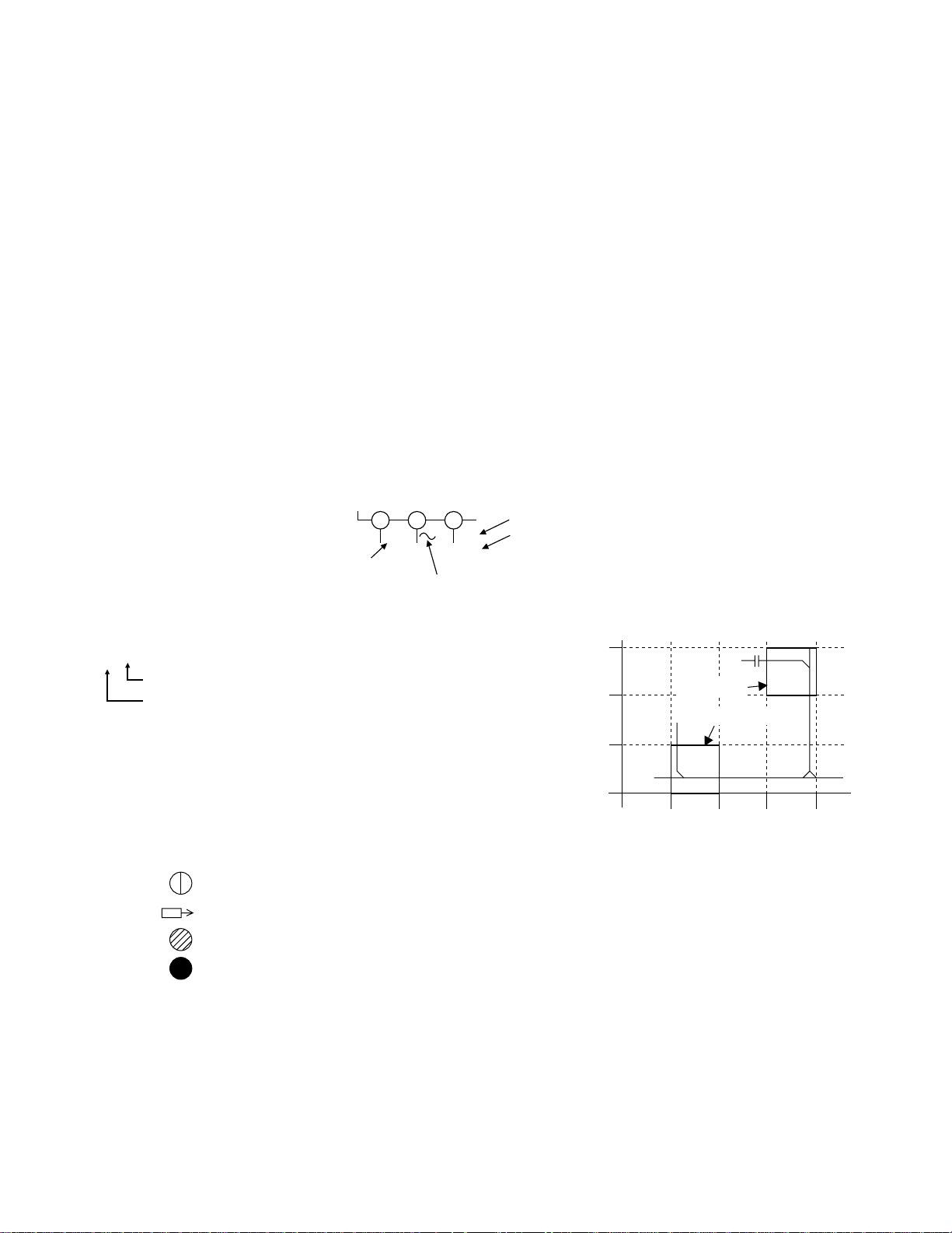
1. The output pin of the 3 pin Regulator ICs is indicated as shown.
Top View
Input
ut
2. For other ICs, pin 1 and every fifth pin are indicated
as shown.
In
in 1
3. The 1st pin of every male connector is indicat ed as
shown.
in 1
Bottom View
5
10
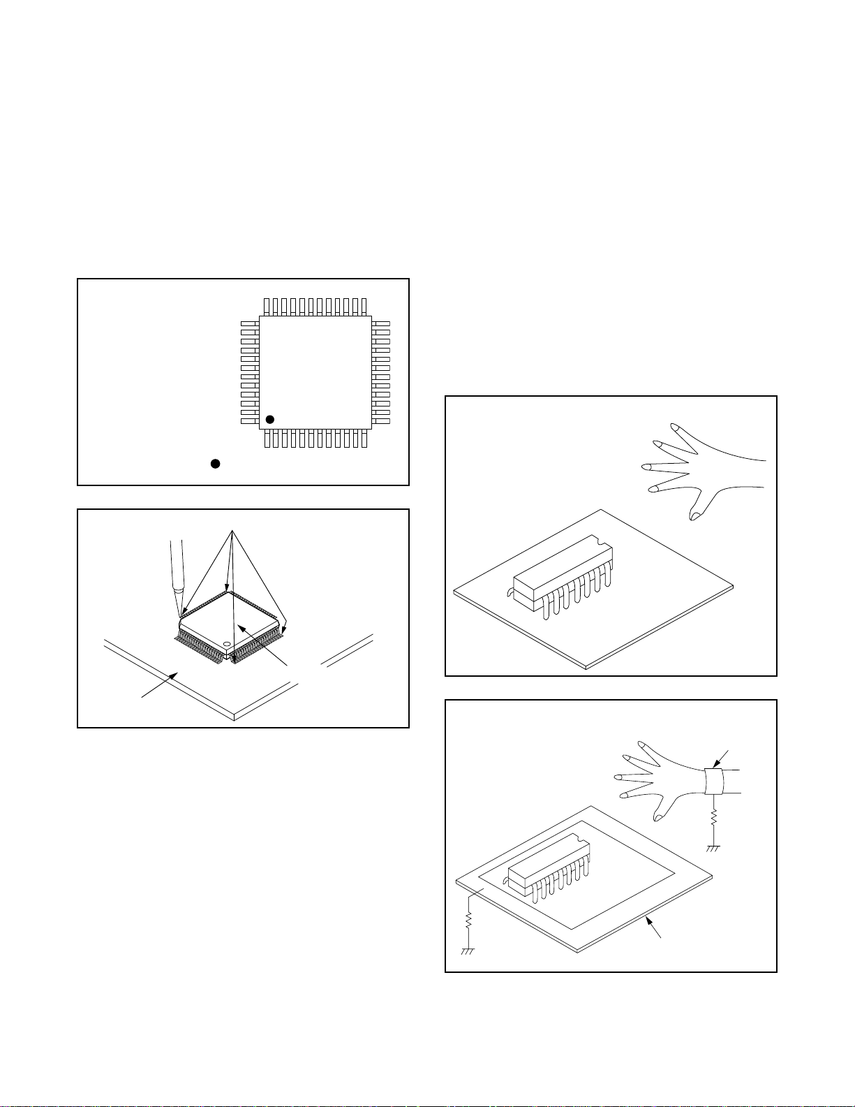
1-2-3 How to Remove / Install Flat
Pack-IC
1. Removal
With Hot-Air Flat Pack-IC Desoldering Machine:.
(1) Prepare the hot-air flat pack-IC desoldering
machine, then apply hot air to the Flat Pack-IC
(about 5 to 6 seconds). (Fig. 1-2-1)
Fig. 1-2-1
(2) Remove the flat pack-IC with tweezers while apply-
ing the hot air.
(3) B ottom of the flat pack-IC is fixed with glue to the
CBA; when removing entire fl at pack-IC, fir st apply
soldering iron to center of the fla t pack-IC and hea t
up. Then remove (glue will be melted). (Fig. 1-2-6)
(4) R elease the flat pack -IC from the CBA usi ng twee-
zers. (Fig. 1-2-6)
1-2-2 Instructions for Connectors
1. When you connec t o r dis con nect the F FC (Flex ib le
Foil Connector) cable, be sure to first disconnect
the AC cord.
2. FFC (Flexible Foil Connector) cable should be
inserted parallel into the connector, not at an angle.
FFC Cable
Connector
CBA
* Be careful to avoid a short circuit.
Caution:
1. Do not supply hot air to the chip parts around the
flat pack-IC for over 6 seconds because damage to
the chip parts may occur. Put maskin g tape a r ound
the flat pack-IC to protect other parts from damage.
(Fig. 1-2-2)
2. The flat pack-IC on th e CB A i s affixed with glue, so
be careful not to break or damage the foil of each
pin or the solder lands under the IC when removing
it.
Hot-air
Flat Pack-IC
Desoldering
CBA
Masking
Tape
Tweezers
Machine
Flat Pack-IC
Fig. 1-2-2
1-3
With Soldering Iron:
F
F
S
rp
or
n
(1)Using desoldering braid, remove the solder from all
pins of the flat pack-IC. Wh en you use solder flux
which is applied to all pins of the f lat pack-IC, you
can remove it easily. (Fig. 1-2-3)
lat Pack-IC
Desoldering Braid
(4) B ottom of the flat pack-IC is fixed with glue to the
CBA; when removing entire fl at pack-IC, fir st apply
soldering iron to center of the fla t pack-IC and hea t
up. Then remove (glue will be melted). (Fig. 1-2-6)
(5) R elease the flat pack -IC from the CBA usi ng twee-
zers. (Fig. 1-2-6)
Note:
When using a sold ering iron, care must be taken
to ensure that the flat pack-IC is not being hel d by
glue. When the flat pack-IC is removed from the
CBA, handle it ge ntl y bec au se it may be damaged
if force is applied.
Soldering Iron
Hot Air Blower
Fig. 1-2-3
(2) Lift each lead of the flat pack-IC upward one by
one, using a sharp pin or wire to which sold er will
not adhere (iron wir e). When heati ng the pins, us e
a fine tip soldering iron or a hot air desoldering
machine. (Fig. 1-2-4)
Iron Wire
Soldering Iron
To Solid
Mounting Point
Sha
Fig. 1-2-5
Pin
ine Tip
oldering Iron
CBA
Fine Tip
Soldering Iro
Fig. 1-2-4
(3)Botto m of the flat pack-IC is fixed with glue t o the
CBA; when removing enti re flat pack-IC, fi rst apply
soldering iron to c en ter o f th e f lat pack-I C an d h eat
up. Then remove (glue will be melted). (Fig. 1-2-6)
(4)Relea se the flat pack-IC fr om the CBA usin g twee-
zers. (Fig. 1-2-6)
Tweezers
Flat Pack-IC
With Iron Wire:
(1)Using desoldering braid, remove the solder from all
Fig. 1-2-6
pins of the flat pack-IC. Wh en you use solder flux
which is applied to all pins of the f lat pack-IC, you
can remove it easily. (Fig. 1-2-3)
(2) Affix the wire to a workbench or solid mounting
point, as shown in Fig. 1-2-5.
(3) While heating the pins using a fine tip soldering
iron or hot air blower, pull up the wire as the solde r
melts so as to lift the IC leads from the CBA contact
pads as shown in Fig. 1-2-5.
1-4
2. Installation
P
i
d
(1) Using desoldering braid, remove the solder from
the foil of each pin of the flat pack-IC on the CBA
so you can install a replac ement flat pack-IC more
easily.
(2) The “I” mark on the flat pack-IC indicates pin 1.
(See Fig. 1-2-7.) Be sure this m ark matches the 1
on the PCB when position ing for installation. Then
presolder the four corners of the flat pack-IC. (S ee
Fig. 1-2-8.)
(3)Solder all pins of the flat pack-IC. Be sure that none
of the pins have solder bridges.
Example :
in 1 of the Flat Pack-IC
s indicated by a " " mark.
Fig. 1-2-7
1-2-4 Instructions for Handling
Semi-conductors
Electrostatic breakdown of the semi-conductors may
occur due to a po tential difference ca used by electr ostatic charge during unpacking or repair work.
1. Ground for Human Body
Be sure to wear a gr oundin g band (1MΩ) that is properly grounded to re move any static electricity th at m ay
be charged on the body.
2. Ground for Workbench
(1) Be sure to place a conductive sheet or copper plate
with proper groundin g (1MΩ) on the workbench or
other surface, where the semi-conductors are to be
placed. Because the static electricity charge on
clothing will no t escape through the body grounding band, be careful to avoid contacting semi-conductors with your clothing.
< Incorrect >
CBA
Presolder
Flat Pack-IC
Fig. 1-2-8
CBA
< Correct >
Grounding Ban
1MΩ
CBA
1MΩ
Conductive Sheet or
Copper Plate
1-5
1-3 NOTES WHEN USING SERVICE MANUAL
(
l
The following shows the contents to be noted when using service manual:
Standard Notes
WARNING
Many electrical and mechanical parts in this chassis
have special characteristics. These characteristics
often pass unnoticed and the protection afforded by
them cannot nece ssar ily b e ob tai ned by us ing repl ac ement components rated for higher voltage, wattage,
Notes:
1. Do not use th e part numb er shown o n these drawings for ordering. The correct part number is shown
in the parts list, and may be slightly different or
amended since these drawings were prepared.
2. All voltages are DC voltages unless otherwise
specified.
etc. Replacement parts that have th ese spe cial safety
characteristics are identified in this manual and its
supplements; electrical comp onents having such features are identified by the mark " ! " in the schematic
diagram and the parts list. Before replacing any of
these components, read the parts list in this manual
carefully. The use of substitute replacement parts that
Values in schematic diagrams
The values, dielectric strength (power capacitance)
and tolerances of the resistors (excluding variable
resistors) and capacitors are indicated in the sche-
matic diagrams using abbreviations.
do not have the same s afety character istics as specified in the parts list may create shock, fire, or other
hazards.
Capacitor Temperature Markings
Mark
(B)
Capacity
change rate
±10%
(F) +30 - 80% 20°C -25~+85°C
(SR)
±15%
Standard
Temperature
temperature
20°C -25~+85°C
20°C -25~+85°C
range
[ Resistors ]
Item Indication
No indication.............................Ω
Value
K..............................................kΩ
M.............................................MΩ
No indication...............1/4W,1/6W
Power capac-
itance
All capacitances other than the
above are indicated in schematic
diagrams.
(Z) +30 - 80% 20°C -10~+70°C
[ Capacitors ]
Capacitors and transistor s are represented by the following symbols.
CBA Symbols
(Top View) (Bottom View)
Bottom View)
E C B
(Top View)
E C B
(Top View)
E C B
+
Electrolytic Capacitor
Transistor or Digital Transistor
(Top View)
NPN
Transistor
NPN Digital
Transistor
E C B
(Top View)
E C B
PNP
Transistor
PNP Digita
Transistor
Item Indication
Value
No indication...........................µF
P..............................................pF
No indication..........................50V
Dielectric
strength
All dielectric strengths other than
50V are indicated in schematic
diagrams.
[ Coils ]
Item Indication
Value
µ...............................................µH
m.............................................mH
1-6
Schematic Diagram Symbols
Digital Transistor
LIST OF CAUTION, NOTES, AND SYMBOLS USED IN THE SCHEMATIC DIAGRAMS ON THE FOLLOWING
T
b
m
ts
1
".
".
3
2
1
PAGES:
1. CAUTION:
FOR CONTINUED PROTECTION AGAINST FIRE HAZARD, REPLACE ONLY WITH THE SAME TYPE FUSE.
2. CAUTION:
Fixed Voltage (or Auto voltage selectable) power supply circuit is used in this unit.
If Main Fuse (F1001) is blown, first check to see that all components in the power supply circuit are not defective
before you connect the AC plug to the AC power supp ly. Otherwi se it may cause some compon ents in the
power supply circuit to fail.
3. Note:
(1) Do not use the part number shown on the drawings for ordering. The correct part number is shown in the parts
list, and may be slightly different or amended since the drawings were prepared.
(2) To maintain original function and reliability of repaired units, use only original replacement parts which are
listed with their part numbers in the parts list section of the service manual.
4. Wire Connectors
(1) Prefix symbol "CN" means "connector" (can disconnect and reconnect).
(2) Prefix symbol "CL" means "wire-solder holes of the PCB" (wire is soldered directly).
5. Voltage indications for PLAY and REC modes on the schematics are as shown below:
he same voltage for
oth PLAY & REC
odes
6. How to read converged lines
-D3
Distinction Area
Line Number
(1 to 3 digits)
Examples:
1. "1-D3" means that line number "1" goes to area "D3
2. "1-B1" means that line number "1" goes to area "B1
7. Test Point Information
: Indicates a test point with a jumper wire across a hole in the PCB.
: Used to indicate a test point with a component lead on foil side.
: Used to indicate a test point with no test pin.
123
5.0
5.0
(2.5)
Indicates that the voltage
is not consistent here.
PLAY mode
Unit: Vol
REC mode
1-B1
AREA D3
AREA B1
1-D3
ABCD
: Used to indicate a test point with a test pin.
1-7

GENERAL INFORMATION2
•
•
•
•
•
•
•
•
e
.
-
he
is
V,
h
ay
3
hours of playback with a T-160 tape.
P
T
T
L
U
R
H
A
V
R
m
without notice.
2-1 SPECIFICATIONS
GENERAL SPECIFICATIONS
layback system: Twin heads,
Helical scanning system
ape width: 12.7mm (1/2 inch)
ape speed SP: 23.39mm/s
P: 11.70mm/s
sable tape: VHS video cassette
F output: UHF channel 22 to 69 for
PAL G/K
orizontal resolution: 230 TV lines
for VHS Terminals
udio input/output: RCA connector ✕2
ideo input/output: RCA connector ✕ 2
F input/output: IEC connector ✕2
ELECTRICAL SPECIFICATIONS
Video input: 0.5~2.0Vp-p
Video output: 1Vp-p75 ohm unbalanced
Video S/N: 42dB
Audio input: -10dBV
Audio output: -6dB
Audio frequency response: 200Hz to 6 kHz
Audio S/N: 40dB
OTHER SPECIFICATIONS
Power consumption: 12W
Operation temperature:
Main input: 110-240V, 50/60Hz
Cabinet dimension:
Weight: Approx. 2.0kg
Accessories: RF cord/ Remote control
Design and specifications are subject to change
5 C to 40 C
360(W) ✕ 92(H) ✕216(D) m
AV cable
2-2 FEATURES
Auto Power On and Stand-by System–
Automatically turns the VCP on as you insert a tape.
When the end of a tape is reached, the VCP will automatically rewind to the beginning. The tape will be
ejected and the VCP will shut itself off.
Auto Play– When you insert a tape without the erase
prevention tab, the VCP starts playback automatically.
Auto Rewinding– When the end of a tape is reached
during playback or fast-forward, the VCP will automatically rewind to the beginning.
Auto Eject– The cassette mechanism will disengage
after rewinding and the tape will be ejected and the
VCP will shut itself off.
Repeat Playback– Allows you to repeat a tape indefinitely without pressing the PLAY button.
Auto Tracking– Adjusts the tracking automatically
for each tape you play.
Auto Head Cleaner– Automatically cleans heads as
you insert or remove a cassette.
Picture Control– Improves playback picture quality
of worn tapes, especially rental tapes.
• Speed Search– You may view the video programm
at a fast speed in either forward or reverse direction
• Line Recording– You can record a programme from
another source via the AUDIO/VIDEO IN sockets.
• Multi color System– PALor MESECAM recorded
tapes can be played back with a multi system receiv
er.
• NTSC Playback– Tapes recorded with the NTSC
system can be played back with this unit via a PAL
system TV set. (This feature is only available in the
SP mode).
• Infrared Remote Control– Allows you to use all t
tape transport controls and STANDBY on/off from
remote location.
• Auto Voltage (AC110-240V, 50/60Hz)– This VCP
designed to match the AC power voltage 110V-240
50/60Hz automaticcaly.
• 2 Step Picture Search Operation– Allows you to
view the video program at a high speed or super hig
speed in either a forward or reverse direction in the
LP mode.
• Two different tape speeds– Select the Standard Pl
(SP mode) and Long Play (LP mode) for up to 5-1/
2-1

2-3 COMPARISON OF MODELS
2-3-1 Comparison of Features ←: Same as on left
ITEM VT-P298GK VT-P198GK/P198GK(U)/(G)
Cabinet Dimension 360(W) x 92(H) x 216(D) mm
Weight 2.0kg
Power Consumption 12W 14W
APPEARANCE
Video Format VHS
Y/C Separation Comb Filter
YNR (Luminance Noise Reduction)
Circuit
VIDEO
New Synchronise Circuit Not Provided
Picture Control Provided (NORMAL/SOFT/SHARP)
Video/Audio Input (Rear) 1/1 (Line Rec)
Video/Audio Input (Front) Not Provided
INPUT/
Video/Audio Output (Rear) 1/1
OUTPUT
Remote Controller VT-RMP298GK VT-RMP98GK/VT-RMP99GK
OSD Ianguages 1(English)
Stereo CM Skip Feature Not Provided
Auto Clock Feature Not Provided
Number of Timer Programming Not Provided
Self Diagnosis Function Provided (5 Modes)
Back-up Time Not Provided
OTHERMECHANISM
SQPB Not Provided
NTSC playback on PAL TV Provided
Surge Absorber Not Provided
Auto Power Off Feature Provided (AUTO REW P-OFF)
Local Broadcast Setting Not Provided
Multi Search Feature Not Provided
Search Speed
FF/REW Time (T-120 Tape) FF/REW: approx. 4min
Head Composition 32 µm/32 µm
Head Material Ferrite
VISS Not Provided
PAL SP:X5/X7, LP:X5/X11,
Provided
NTSC SP:X5
←
←
←
←
←
←
←
←
←
←
←
←
←
←
←
←
←
←
←
←
←
←
←
←
←
←
←
2-2
2-3-2 Comparison of Main Control ICs ←: Same as on left
ITEM OPERATION VT-P298GK VT-P198GK/P198GK(U)/(G)
Video Video Signal Process LA71584M (IC301)
Audio
System Control
Timer Display Driver Included in IC501
Power Switching Driver Not Provided
FM Audio Signal Process Not Provided
Linear Audio Signal Process Included in IC301
Main Microcomputer µP M37762MCA-AB2GP (IC501) M37768M6A-1D6GP (IC501)
VCR-EEP ROM BR24C01AF-W (IC503)
Reset Not Provided
Loading Motor Drive
Cylinder/Loading Motor
Control
Power Reset
Included in IC on the Capstan Motor
CBA
Included in IC on the Capstan Motor
CBA
Included in IC on the Capstan Motor
CBA
M24C01-MN6 (IC505)
←
←
←
←
←
←
←
←
←
2-3
2-4 MECHANICAL TROUBLE INDICATOR
Note:
The following symbols will appear on the indicator panel to indicate mechanical trouble.Display panel.
Indicator Mode
at 0.4Hz interval When power safety is not functioning properly.
at 0.8Hz interval When capstan/reel mechanism is not functioning properly.
REPEAT
at 1.6Hz interval When tape loading mechanism is not functioning properly.
at 3.2Hz interval When cassette loading mechanism is not functioning properly.
at 6.4Hz interval When the drum is not functioning properly.
2-4
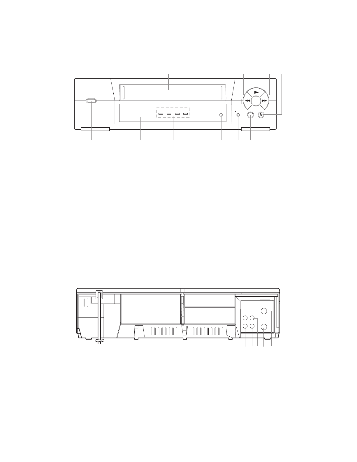
– FRONT VIEW –
PLAY
REW
REC
REC
F.FWD
STOP/EJECT
REPEAT
REPEAT
SYSTEM
SELECT
OPERATE
STANDBY ON
678911
12435
10
AUDIO
VIDEO
RF OUT
AERIAL
OUT IN
1312 14 1715 16
1
1
1
2-5 OPERATING CONTROLS AND FUNCTIONS
1 CASSETTE COMPARTMENT
2 REW (VISUAL SEARCH) button– Press to
rewind tape or to view video in reverse during
playback at a fast speed. Press the PLAY button to
return to normal speed.
3 PLAY button– Press to begin playback of a tape.
4 F. FWD (VISUAL SEARCH) button– Press to
advance tape or to view video in forward direction
during playback at a fast speed. Press the PLAY
button to return to normal speed.
5 STOP/EJECT button– Press to stop tape motion /
remove tape from the appliance.
6 REPEAT button– Press to repeat playback
automatically.
7 REC button– Press to record a broadcast from
another source.
– REAR VIEW AND TERMINALS –
8 SYSTEM SELECT button– Press to select the
colour system PAL, MESECAM, NTSC 4.43 or
NTSC3.58. (See “PLAYBACK” section.)
9 INDICATOR
• STANDBY– Lights on when power is connected.
• ON– Lights on when the VCP turns on.
• REPEAT– Lights on when the Repeat Playback is
functioned.
• REC– Lights on during recording.
10 Remote Sensor window– Receives the infrared
control signals from the remote control unit.
11 OPERATE button– Press to turn the VCP on and
stand-by.
2 AUDIO OUTjack– Connect to the audio input
jack of your TV.
3 VIDEO OUT jack– Connect to the video input
jack of your TV.
4 VIDEO IN jack– Connect to video output jack of
your video equipment.
15 AUDIO IN jack– Connect to audio output jack of
your audio equipment.
16 RF OUT jack– Connect to aerial jack of your TV.
17 AERIALjack– Connect to the TV aerial coaxial
cable.
2-5
You can operate most of your VCP’s tape transport functions from the Remote Control (supplied).
T
he buttons on the Remote Control have the same functions as the corresponding buttons on the VCP.
H
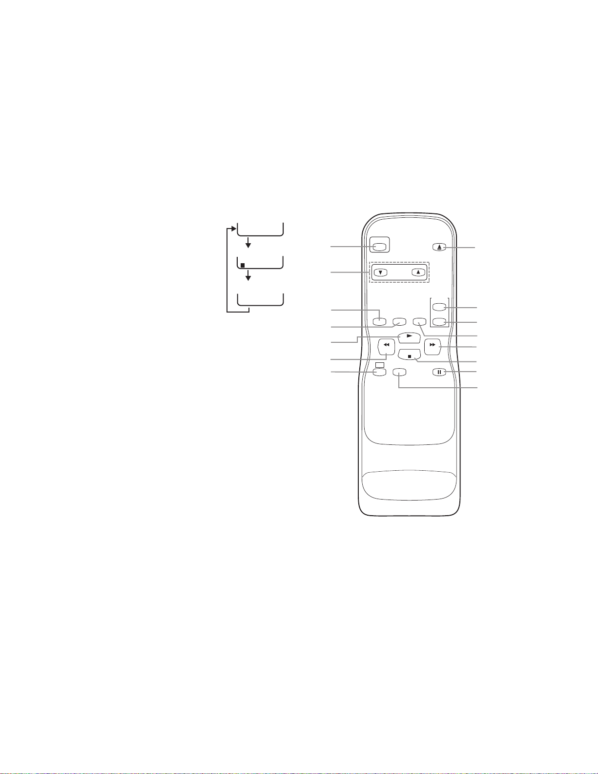
1
1
1
er
0:12:34 SP
0:12:34
<OFF mode>
<COUNTER mode>
Press once
Press once
5 seconds
<STATUS mode>
OPERATE
REW
PLAY
STOP
F.FWD
PAUSE/STILL
REPEAT
DISPLAY
REC
SPEED
EJECT
PICTURE
SELECT
RESET
COUNTER
MEMORY
TRACKING
2
6
7
5
3
4
1
8
9
10
11
13
15
14
12
OW TO USE THE REMOTE CONTROL
1 OPERATE button– Press to turn the VCP on and
stand-by.
2 TRACKING buttons– Press to adjust to minimize
video “noise” (lines or dots on screen) during
playback. Most often, this is necessary when
playing pre-recorded tapes or tapes recorded on
other VCP’s.
3 DISPLAY button– Press to
display the tape status, TV screen.
Each time you press this button,
TV screen will change as shown.
4 REPEAT button– Press to repeat
playback automatically.
5 PLAY button– Press to begin
playback of the tape.
6 REW (VISUAL SEARCH)
button– Press to rewind the tape.
Or press to view the picture rapidly in reverse,
during the Playback mode.
7 REC button– Press to begin recording.
8 SPEED button– Press to set desired recording
speed (SP/LP).
9 PAUSE/STILL button– Press to stop the tape
temporarily during playback or recording.
0 STOPbutton– Press to stop tape motion.
1 F.FWD (VISUAL SEARCH) button– Press to
move the tape forward rapidly. Or press to view the
picture rapidly in forward during the Playback
mode.
2 PICTURE SELECT button– Press to improve the
playback picture quality of noisy tapes. (ex: rental
tape etc.)
13 COUNTER RESET button– Press to reset count
to 0:00:00.
14 COUNTER MEMORYbutton– Press to set
counter memory on and off.
15 EJECT button– Press to remove tape from the
VCP.
2-6
MAINTENANCE AND INSPECTION3
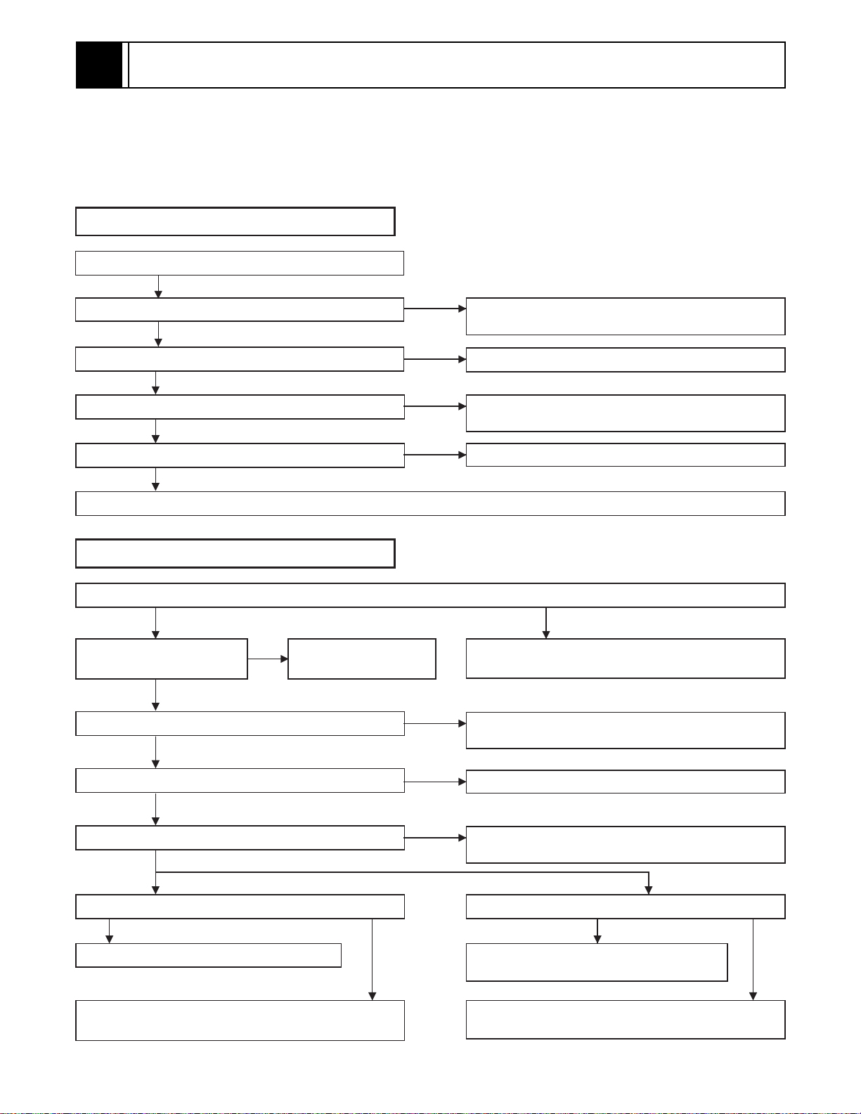
3-1 TROUBLESHOOTING
Troubleshooting is how to service for the specifying malfunction or poor parts.
Detect malfunction or poor parts and service as the following charts.
Video problem 1 (No recording Video)
LINE INPUT (AV)
Check Video signal at pin (38) of IC301. Check AV cable, JK752 and line between JK752 and
OK
Check Video signal at pins (31, 51, 72) of IC301.
OK
Check Video signal at pin (20) of IC301.
OK
Check Video signal at pin (90) of IC301.
OK
Cleaning the Video Head. (See page 3-5.) Or check Cylinder Assembly and service it if defective.
NG
NG
NG
NG
pin (38) of IC301, and service it if defective.
Check IC301, X301, etc., and service it if defective.
Check Q304 and their periphery, and service it if
defective.
Check IC301, X301, etc., and service it if defective.
Video problem 2 (No playback Video)
Check Video signal at pins (88, 90) of IC301 and TP301 (C-PB).
OK
Check Video signal at
pins (51, 72) of IC301.
OK
Check Video signal at pin (20) of IC301.
OK
Check Video signal at pin (29) of IC301.
NG
Check IC301, X301, etc.,
and service it if defective.
NG
NG
Cleaning the Video Head. (See page 3-5.) Or check
Cylinder Assembly and service it if defective.
Check Q304 and their periphery, and service it if
defective.
Check IC301, X301, etc., and service it if defective.
NG
OK
Check Video signal at pin (52) of IC501.
OK
RF OUT LINE OUT
Check Video signal at pin (6) of MD701.
OK OK
Check MD701 and service it if defective.
Check line between pin (52) of IC501 and pin (6) of
MD701, and service it if defective.
NG
NG NG
Check IC501, X501 and line between pin (29) of IC301
and pin (50) of IC501, and service it if defective.
Check Video signal at pin (19) of JK751.
Check JK751 and AV cable, and service it if
defective.
Check line between pin (52) of IC501 and JK751, and
service it if defective.
3-1
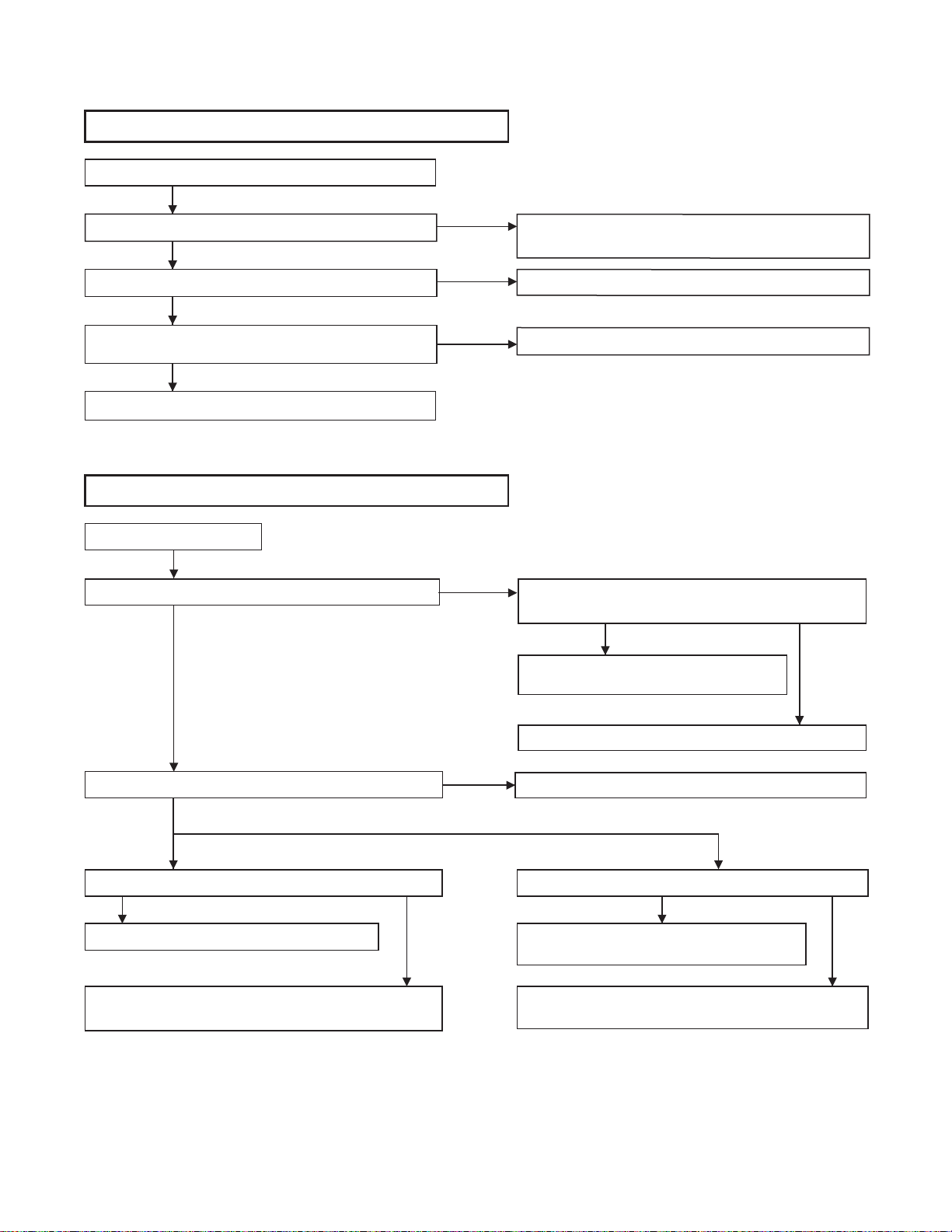
Audio problem 1 (No recording Normal Audio)
LINE INPUT (AV)
Check Audio signal at pin (76) of IC301.
OK
Check Audio signal at pins (7, 96) of IC301.
OK
Check Tape interchangeability alignment.
(See page 3-5.)
NG
Cleaning the Audio Control Head. (See page 3-5.)
NG
NG
NG
Audio problem 2 (No playback Normal Audio)
(AV)
Check Audio signal at pin (4) of IC301.
OK
NG
Check AV cable, JK752 and line between JK752 and
pin (76) of IC301, and service it if defective.
Check IC301, X301, etc., and service it if defective.
Check ACE Head Assembly and service it if defective.
Check Tape interchangeability
alignment. (See page 5-5.)
NG
Check ACE Head Assembly and service
it if defective.
OK
Check Audio signal at pin (96) of IC301.
OK
RF OUT LINE OUT
Check Audio signal at pin (2) of MD701.
OK OK
Check MD701 and service it if defective.
Check line between pin (96) of IC301 and pin (2) of
MD701, and service it if defective.
3-2
Cleaning the Audio Control Head. (See page 3-5.)
NG
NG NG
Check IC301, X301, etc., and service it if defective.
Check
Audio
signal at JK751.
Check JK751 and AV cable, and service it if
defective.
Check line between pin (96) of IC301 and JK751, and
service it if defective.
Power problem
It is highly recommended that a variable isola tion
transformer which can monitor current be used.
(Alternatively a variable AC source which monitors current will do). Read directions below befo re
power is added!
Repair method
CHECK
Connect unit to the isolation transformer and slowly increase the AC supply while monitoring the current, if it
draws too much current (Be ware fuse
is rated for 1.6 amps), then turn off
supply and do repair method #1.
NO
Check whether the primary rectifying
DC of the Switching power supply has
an output. (Reading should be about
168V.)
YES
With the primary DC working check
the secondary 5V.
YES
Are the 12V and 5V higher than
normal?
NO
Although the secondary 5V is working,
are any of the other voltages higher
than normal (12V)?
NO
There is no problem on the SW power
supply.
YES
NO
NO
YES
YES
#1
#2
#3
#4
#5
1] Check for any defect ive parts while the secondary
rectifying diodes are disconnected (D011, D013 and
D014) perform a diode check in both forward and
reverse directions through a tester.
2] Remove the following components and check for
defects: snubber diode ( D00 5) , sw itc hi ng F ET ( Q00 1) ,
source resistor (R006), control transistor (Q002).
Repair method #2
Check the fuse 1.6A (F00 1), primary rectifying d iodes
(D001-D004) as possible problems. Remove the
above mentioned parts and check them. The circuit
which turns on switching FET (Q001) may be
regarded as a possibl e cause, even if the load at the
secondary side is shorted, it can't be detected
because switching FET (Q001) isn't operating. Perform check according to the step 1 and 2 of repair
method #1 and check the following parts:
(Remove the part from PCB)
Switching FET (Q001), source resistor (R006), gate
resistor (R008) and start resistor (R003, R004, R005
and R028).
Repair method #3
A circuit to turn on switching FET (Q001) may not work
and this may be regard ed as a cau se of trouble. Even
if the load at the secondary side is short-circuited, it
cannot be detected because switching FET (Q001)
does not turn on. Therefor e, perform check acco rding
to the steps 1] and 2] of the repair method #1 and execute the under-mentioned parts breakage check.
(Remove the part from PCB.)
switching FET (Q001), source resistor (R006), control
transistor (Q002) , gate resist or (R008) and start resistor (R003, R004, R005 and R028).
Repair method #4
Repair method #1
(Power must be off)
Short circuit in the s econd ary si de. c heck di ode D 011,
D013, D014, switching FET (Q001), control transi stor
(Q002), diode (D006, D018), and resistor (R014)
replace as necessary.
Disconnect 44V diod e (D011), 12V di ode (D013), 5V
diode (D014). Check the load continuity of 44V line,
12V line and 5V line through a tester (resistance
range).
If the tester indic ates a lower resistance v alue around
0 ohm, the line is short-circuited.
Before repairing the switc hing power supply, find out
the short-circuited area of such line and repair it.
If the tester does not indicate any low resistance value
(around 0 ohm), no l oad is shor t-cir cuited a nd the re i s
no problem.
The feedback c ircuit whic h is monitor ed by the output
of voltage may not w ork and this may be regarded as
a possible cause, rem ove control transis tor Q002 and
check for defects. More ov er, a photo coupler (IC001)
and transistor (Q004) may be defective, replace any
defective parts with factory originals.
Repair method #5
If the output voltage of the secondary side is slightly
high, the line load may be in the "OPEN" state and this
may be regarded as a cause of troub le. If there is no
output voltage on the secondary side, the rectifying
diodes (D011) and (D013) may be defective.
3-3
3-2 STANDARD MAINTEN ANCE
3-2-1 Service Schedule of Components
h: Hours : Check I: Change
Deck Periodic Service Schedule
Ref.No. Part Name 1,0 00 h 2,000 h 3,0 00 h 4,000 h
B2
B3 Loading Motor Assembly I
B8
B587
B31 ACE Head Assembly I
B573,B574
B37
B52 Cap Belt II
B73
B133,B134
B410 Pinch Arm(A) Assembly II
B414
B416
Cylinder Assembly
Pulley Assembly
Tension Lever Assembly
Reel (SP)(D2), Reel (TU)(D2)
Capstan Motor
FE Head
Idler Gear, Idler Arm
M Brake (SP) Assembly
M Brake (TU) Assembly
II
II
II
I
II
I
II
II
II
B525 LDG Belt II
B569
Notes:
1.Clean all parts for the tape tr ansport (Upp er Drum with Video Head / Pinch Roll er / Audio Control Head / Full
Erase Head) using 90% lsopropyl Alcohol.
2.After cleaning the parts, do all DECK ADJUSTMENTS.
3.For the reference numbers listed above, refer to Deck Exploded Views.
Cam Holder (F)
II
3-4
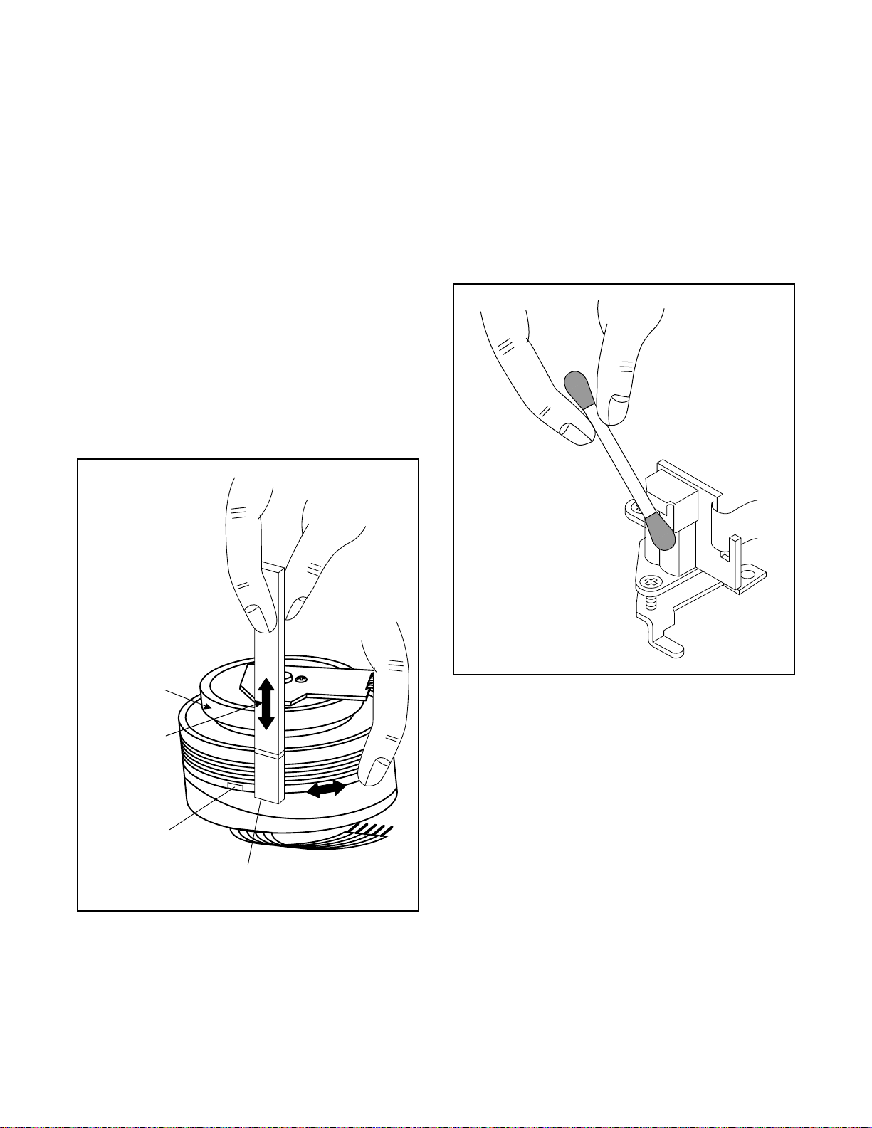
3-2-2 Cleaning
V
d
Cleaning of Video Head
Clean the head with a head cleanin g stick or chamois
cloth.
Procedure
1.Remove the top cabinet.
2.Put on a glove (thin type) to avoid touching the
upper and lower drum with your bare hand.
3.Put a few d rops of 90% Isopropyl alcohol o n the
head cleaning stick or on the chamois cloth and,
by slightly pressi ng it a gai ns t th e he ad tip , tur n the
upper drum to the right and to the left.
Notes:
1.The video head surface is made of very hard
material, but since it i s very thin, avoid clea ning it
vertically.
2.Wait for the cleaned part to dry thorough ly before
operating the unit.
3.Do not reuse a stained head cleaning stick or a
stained chamois cloth.
Cleaning of ACE Head
Clean the head with a cotton swab.
Procedure
1.Remove the top cabinet.
2.Dip the cotton swab i n 90% Isopropyl alcoho l and
clean the ACE head. Be careful not to damage the
upper drum and other tape running parts.
Notes:
1.Avoid cleaning the ACE head vertically.
2.Wait for the cleaned part to dry thoroughly before
operating the unit or damage may occur.
ACE Hea
Upper
Cylinder
Do Not !
ideo Head
Cleaning Stick
3-5

DISASSEMBLY 4
4-1 CABINET DISASSEMBLY INSTRUCTIONS
4-1-1 Disassembly Flowchart
This flowchart indicates the disassem bly steps to gain
access to item(s) to be serviced. When reassembling,
follow the steps in reverse order. Bend, route, and
dress the cables as they were originally.
[1] Top Case
[2] Front Assembly
[3] VCR Chassis Unit
[7] Deck Assembly
[8] Main CBA
[4] Cylinder Shield
[5] Function CBA
[6] Switch CBA
4-1-2. Disassembly Method
ID/
LOC.
No.
[1] Top Case 4-1-1 3(S-1) [2]
[3]
PART
Front
Assembly
VCR
Chassis
Unit
Fig.
No.
4-1-2 *3(L-1),*4(L-2) -
4-1-3 5(S-2), (S-3) 1
REMOVAL
REMOVE/*UNHOOK/
UNLOCK/RELEASE/
UNPLUG/DESOLDER
Note
(1): Identification (location) No. of parts in the figures
(2):Name of the part
(3):Figure Number for reference
(4): Identification of parts to be removed, unhooked,
unlocked, released, unplugged, unclamped, or
desoldered.
P=Spring, L=Locking Tab, S=Screw,
CN=Connector
*=Unhook, Unlock, Release, Unplug, or Desolder
e.g. 2(S-2) = two Screws (S-2),
2(L-2) = two Locking Tabs (L-2)
(5):Refer to “Reference Notes.”
Reference Notes
CAUTION: Locking Tabs (L-1) and (L-2) are fragile.
Be careful not to break them.
1. Remove five Screws (S-2). Then slowly lift the VCR
Chassis Unit (Deck Assembly, Function CBA,
Power SW CBA and Main CBA) up.
2. When reassembling, solder wire jumpers as shown
in Fig. 4-1-4.
3. Before installing the Deck Assembly, be sure to
place the pin of LD-SW on Main CBA as sho wn in
Fig. D5. Then, install the Deck Assembly while
aligning the hole of C am Gear with the pin of LDSW, the shaft of Cam Gear with the hole of L D- SW
as shown in Fig. 4-1-5.
(S-1)
Cylinder
[4]
Shield
Function
[5]
CBA
Switch
[6]
CBA
Deck
[7]
Assembly
[8] Main CBA
↓
(1)
↓
(2)
4-1-4 2(S-4) -
4-1-4 Desolder -
4-1-4 Desolder -
4-1-4,
4-1-5
4-1-4,
4-1-5
(S-5), (S-6), (S-7),
Shield Cover, 2(W-1)
Desolder
---------- -
↓
(3)
↓
(4)
[1] T op Case
2,3
↓
(5)
Fig. 4-1-1
4-1

(L-2)
(L-2)
(S-4)
(S-4)
[4]Cylinder Shield
[2] Front
Assembly
[3] VCR
Chassis Unit
(S-3)
(L-1)
(S-2)
(S-2)
Fig. 4-1-2
[7] Deck
Assembly
(S-6)
[6] Switch
CBA
Desolder
Shield
Cover
FE Head
(W-1)
(S-5)
Desolder
[5] Function CBA
Cylinder
Assembly
ACE Head
Assembly
(W-1)
[8] Main
CBA
(S-7)
Fig. 4-1-3
From
Capstan
Motor
Assembly
Printing
side
Lead connections of Deck Assembly and Main CBA
From
ACE Head
Assembly
Lead with
blue stripe
Desolder
BOTT OM VIEW
From
Cylinder
Assembly
Desolder
From
FE Head
Lead with
blue stripe
Fig. 4-1-4
4-2

Pin
[8] Main CBA
[7] Deck Assembly
SW507
LD-SW
Cam Gear
Shaft
LD-SW
Hole
Hole
Pin
[8] Main CBA
Fig. 4-1-5
4-3

4-2 DISASSEMBLY/ASSEMBLY PROCEDURES OF DECK
MECHANISM
Before following the procedures described below, be sure to remove the deck assembly from the cabinet. (Refer to
CABINET DISASSEMBLY INSTRUCTIONS on page 4-1.)
All the following proc edures, including those for adjustment and replacement of parts, should be done in Ejec t
mode; see the positio ns of [41 ] and [42] in Fig. DM1 on page 4-6. Wh en reass embli ng, foll ow the ste ps in reverse
order.
STEP
/LOC.
START-
ING
No.
[1] [1] Guide Holder A T DM3 2(S-1)
[2] [1] Cassette Holder Assembly T DM4
[3] [2] Slider (SP) T DM5 *(L-1)
[4] [2] Slider (TU) T DM5 *(L-2)
[5] [4] Lock Lever T DM5 *(L-3),*(P-1)
[6] [2] Cassette Plate T DM5 (S-1A)
[7] [7] Cylinder Assembly T DM1,DM6 Desolder, 3(S-2)
[8] [8] Loading Motor Assembly T DM1,DM7
[9] [9] ACE Head Assembly T DM1,DM7 (S-4)
[10] [2] Tape Guide Arm Assembly T DM1,DM8 *(P-2)
[11] [10] C Door Opener T DM1,DM8 *(L-4)
[12] [11] Pinch Arm (B) T DM1,DM8 *(P-3)
[13] [12] Pinch Arm Assembly T DM1,DM8
[14] [14] FE Head Assembly T DM1,DM9 (S-5)
[15] [15] Prism T DM1,DM9 (S-6)
[16] [2],[15] Sensor Gear T DM1,DM15
[17] [2] Slide r Shaft T DM10 *(L-5)
[18] [17] C Drive Lever (SP) T DM10
[19] [17] C Drive Lever (TU) T DM10 (S-7),*(P-4)
[20]
[21] [21] Clutch Assembly B DM2,DM12 (C-1)
[22] [22] Cam Holder (F) B DM2,DM12 *(L-6)
[23] [23] Cam Gear (B) B DM2,DM12 (C-4)*(P-5)
[24] [24] Mode Gear B DM2,DM13 (C-2)
[25]
[26] [22] Worm Holder B DM2,DM13 (S-9),*(L-9),*(L-10)
[27] [26] Pulley Assembly B DM2,DM13
[28] [25],[26] Cam Gear (A) B DM2,D M13
[29] [25] Idler Gear B DM1,DM14
[30] [29] Idler Arm B DM1,DM14 *(L-11)
[31] [25] BT Arm B DM2,DM14 *(P-6)
[32] [25]
No.
[7],[8],
[10]
[21],[23],
[24]
Capstan Motor B DM2,DM11 3(S-8), Cap Belt
Mode Lever B DM2,DM13 (C-3), *(L-8)
Loading Arm (SP)
Assembly
PART
Fig. No.
B DM2,DM14
REMOVAL INSTALLATION
REMOVE/*UNHOOK/
UNLOCK/RELEASE/
UNPLUG/DESOLDER
Desolder, LDG Belt,
2(S-3)
ADJUSTMENT
CONDITION
(+)Refer to Alignment
Sec.Page 4-12
4-4

STEP
/LOC.
START-
ING
No.
[33]
[34] [2],[25] M Brake (TU) Assembly T DM1,DM15 *(P-7), Brake Belt
[35] [2],[25] M Brake (SP) Assembly T DM1,DM15 *(P-8)
[36] [35] Tension Lever Assembly T DM1,DM15
[37] [36] T Lever Holder T DM15 *(L-12)
[38] [34] Reel (TU)(D2) T DM1,DM15
[39] [38] M Gear T DM1,DM15
[40] [36] Reel (SP)(D2) T DM1,DM15
[41] [32],[36]
[42] [33]
[43] [19] TG Post Assembly T DM1,DM16 *(L-13)
[44] [28] Rack Assembly R DM17
[45] [44] F Door Opener R DM17
[46] [46] Cleaner Assembly T DM1,DM6
[47] [46] CL Post T DM6 *(L-14)
↓
(1)
No.
[32]
↓
(2)
Loading Arm (TU)
Assembly
Moving Guide S
Preparation
Moving Guide T
Preparation
PART
↓
(3)
Fig. No.
B DM2,DM14
T DM1,DM16
T DM1,DM16
↓
(4)
↓
(5)
REMOVAL INSTALLATION
REMOVE/*UNHOOK/
UNLOCK/RELEASE/
UNPLUG/DESOLDER
↓
(6)
ADJUSTMENT
CONDITION
(+)Refer to Alignment
Sec.Page 4-12
(+)Refer to Alignment
Sec.Page 4-12
↓
(7)
(1): Follow steps in sequence. When reassembling, follow the steps in reverse order.
These numbers are also used as identification (location) No. of parts in the figures.
(2): Indicates the part to start disassembling with in order to disassemble the part in column (1).
(3):Name of the part
(4): Location of the part: T=Top B=Bottom R=Right L=Left
(5): Figure Number
(6): Identification of parts to be removed, unhooked, unlocked, released, unplugged, unclamped, or desoldered.
P=Spring, W=Washer, C=Cut Washer, S=Screw, *=Unhook, Unlock, Release, Unplug, or Desolder
e.g., 2(L-2) = two Locking Tabs (L-2).
(7): Adjustment Information for Installation
(+):Refer to Deck Exploded Views for lubrication.
.
4-5

T op View
[14]
[36]
[35]
[42][41] [43][9]
[7] [46] [8]
[13]
[11]
[15]
[10]
[12]
[34]
Bottom View
[26]
[27]
[23]
[28]
[20]
[29]
[30][40] [16] [39] [38]
Fig. DM1
[33]
[32]
[24]
[25]
4-6
[31][21][22]
Fig. DM2

(S-1)
[1]
(S-1)
Fig. DM3
(S-1A)
[7]
(L-1)
[3]
[6]
(L-2)
(P-1)
[46]
[4]
(L-3)
[5]
Fig. DM5
Pin D
Pin C
Slots B
First, while pushing the locking tab as
shown at right, slide and pull up the right
side on [2] to release Pin A and Pin B from
the slots A.
Then, remove Pin C and Pin D on [2] from
the slots B as shown.
[2]
Pin A
Locking tab
2
Pull up
A
1
Slide
Pin B
Slot A
Slot A
View for A
Fig. DM4
Desolder
from bottom
(S-2)
View for A
[47]
(L-14)
A
Lead with
Red Stripe
Fig. DM6
4-7

[9]
)
)
(S-4)
[8]
A
[14]
(S-5)
[16]
(S-6)
[15]
(S-3)
Adj. Screw
[13]
LDG
Belt
Desolder
from bottom
Lead with White Stripe
View for A
[8]
Fig. DM7
[11]
(L-4)
(P-3)
[12]
[10]
Fig. DM9
[18]
(L-5)
[17]
[19]
(P-4
(P-2
4-8
Pin of [12]
View for A
Pin of [10]
Groove of [28]
[28]
A
When reassembling [10] and
[12], confirm that pin of [10]
and pin of [12] are in the
groove of [28] as shown.
Fig. DM8
(S-7)
Fig. DM10

1
Cap Belt
]
[20]
(S-8)
[23]
(C-4)
(P-5)
(P-5)
[22]
(L-6)
(C-1)
[21
Fig. DM1
Pin on
bottom
of [23]
[28]
When installing [23], install
the spring (P-5) to [28] as
shown in the left figure, and
then install [23] while
pressing the spring (P-5) to
the direction of the arrow in
the left figure and confirming
that the position of the
spring (P-5) is placed as
shown in the left figure.
[23]
T op Vie w
Pin on [22]
[28]
Position of pin on [22]
Fig. DM12
4-9

[25]
)
(C-3)
[31]
(P-6)
Refer to the Alignment
Section, Page 4-12.
(L-10)
[27]
[28]
Pin of [34]
(S-9)
(L-8)
[26]
(L-9)
Position of Mode Lever when installed
Pin of [31]
Pin of [35]
(C-2)
[24]
[30]
[29]
(L-11)
[40]
[36]
[33]
[32]
Fig. DM14
Break belt
(P-7
[34]
Bottom View
[28]
T op Vie w
Align [25] and [28] as shown.
First groove on [28]
First tooth on [44]
[28]
When reassembling [28],
align the first groove on
[28] to the first tooth on
[44] as shown.
[25]
Fig. DM13
(P-8)
[35]
[37]
turn
turn
[39]
(L-12)
[38]
turn
Fig. DM15
4-10

[41]
[42]
[43]
(L-13)
Fig. DM16
[45]
[44]
Slide
Fig. DM17
4-11

4-3 ALIGNMENT PROCEDURES OF MECHANISM
2
The following procedures describe how to align the
individual gears and levers that make up the tape loading/unloading mechanism. Since information about the
state of the mechanism is provided to the System
Control Circuit only through the Mode Switch, it is
essential that the corr ect relatio nship bet ween ind ividual gears and levers be maintained.
All alignments are to be performed with the mechanism in Eject mode, in the sequenc e given. Each
procedure assumes th at all pr evious pro cedures hav e
been completed.
IMPORTANT:
If any one of these alignments is not performed
properly, even if off by only one tooth, the unit will
unload or stop and i t may result in damage to the
mechanical or electrical parts.
Alignment points in Eject Position
T op View
Alignment 3
Alignment 1
Loading Arm (SP) and (TU) Assembly
Install Loading Arm ( SP) and (TU) Assembly so that
their triangle marks point to each other as shown in
Fig. 4-3-2.
Alignment 2
Mode Gear
Keeping the two triangles pointing at each other, install
the Loading Arm (SP) Assembly so that the last tooth
of the gear meets the most ins ide teeth of the Mode
Gear. See Fig. 4-3-2.
Alignment 1
Triangle Marks
Loading Arm
(SP) Assembly
Last T ooth
Alignment 2
Loading Arm
(TU) Assembly
Most inside teeth
of Mode Gear
Mode Gear
Fig. 4-3-2
Bottom View
4-12
Alignment 1
Alignment
Fig. 4-3-1
Alignment 3
Cam Gear (A), Rack Assembly
Install the Rack As s emb ly s o that th e first tooth on the
gear of the Rack Assembly meets the firs t groove on
the Cam Gear (A) as shown in Fig. 4-3-3.
T op Vie w
First groove
on the Cam Gear (A)(HI)
Cam Gear (A)(HI)
Gear on Rack Assembly
Alignment 3
First tooth
Fig. 4-3-3

ADJUSTMENT5
5-1 PREPARATION FOR SERVICING
5-1-1 How to Enter the Service Mode
About Optical Sensors
Caution:
An optical sensor system is used for the Tape Start
and End Sensors on this equipment. Carefully read
and follow the instructions below. Otherwise the unit
may operate erratically.
What to do for preparation
Insert a tape into the D eck Mechanis m Assembly and
press the PLAY button. The tape will be loaded into
the Deck Mechanism Ass embly. Make sure the power
is on, connect TP507 (SENSOR INHIBITION) to
(GND). This will stop the function of Tape Start Sensor,
Tape End Se ns or an d Reel Sensors. (I f th ese T P s ar e
connected before plu gging in the unit, the function of
the sensors will stay valid.) See Fig. 5-1-1.
Note: Because the Tape End Sensors are inactive, do
not run a tape all the way to the start or the end of the
tape to avoid tape damage.
Q504
Q505
TP507
S-INH
Fig. 5-1-1
5-1

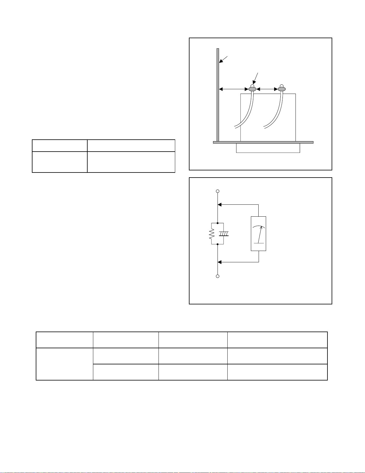
5-2 FIXTURE AND TAPE FOR ADJUSTMENT
1. Alignment Tape
No. 7099052 (MH-2)
3. Flat Screwdriver
(Purchase Locally)
2. Guide Roller Adj. Screwdriver
No. 7099028
5-2-1 How To Use The Fixtures And Tape
Item No. Name Part No. Adjustment
1 Alignment Tape 7099052
2 Guide Roller Adj. Screwdriver 7099028 I G uide Roller
3 Flat Screwdriver Purchase Locally I X Value Alignment
I Head Switching Point
I Tape Interchangeability Alignment
5-2

5-3 ELECTRICAL ADJUSTMENT INSTRUCTIONS
e
2
)
C
C
c
General Note: "CBA" is an abbreviation for
"Circuit Board Assembly."
NOTE:
1.Electrical adjus tments are required after replacing
circuit components and certain mechanical parts. It
is important to do these adjustments only after all
repairs and replacements have been completed.
Also, do not attem pt thes e adj ustmen ts unles s the
proper equipment is available .
2.To per form these alignment / confirmation proce dures, make sure that the tracki ng co ntrol is set in
the center position: Press either "TRACKING +5??" or
"TRACKING -" button on the remote control unit
first, then the "PLAY" button on the front panel.
EXT. Syncronize Trigger Point
H1
1.0H
H2
Figure 1
6.5H±1H
Switching Pulse
0.5H
V-Syn
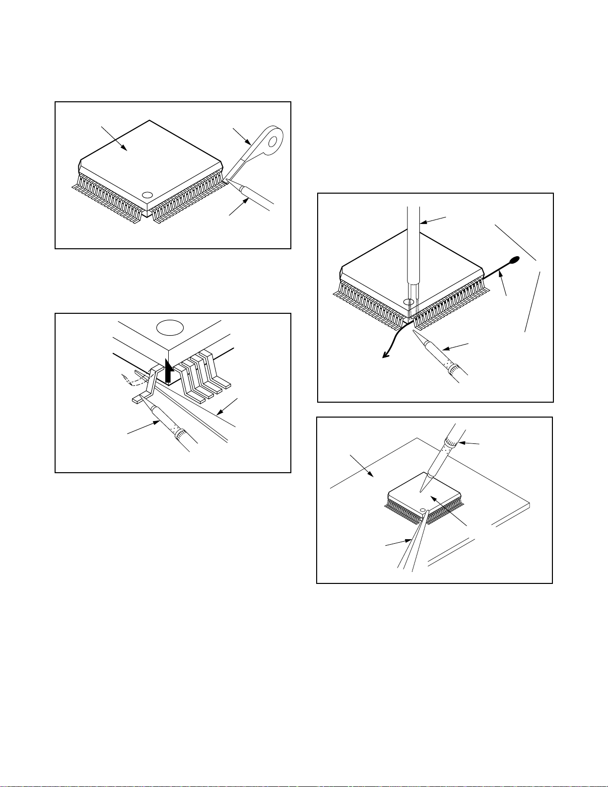
5-3-1 Test Equipment Required
1.Oscilloscope: Dual-trace with 10:1 probe,
V-Range: 0.001~50V/Div.,
F-Range: DC~AC-20MHz
2.Alignment Tape (MH-2)
5-3-2 Head Switching Position
Adjustment
Purpose:
To determine the Head Switching point during
playback.
Symptom of Mi sadjustm e n t:
May cause Head Switchi ng noise or vertical jitter
in the picture.
Test point Adj.Point Mode Input
TP751(V-OUT)
TP502(RF-SW)
GND
Tape
VR501
(Switching Point)
(MAIN CBA)
Measurement
Equipment
PLAY
(SP)
Spec.
Reference Notes:
Playback the Alignment tape and adjust VR501 so that
the V-sync front edg e of the CH1 video output waveform is at the 6.5H±1H delayed position from the rising
edge of the CH2 head switching pulse waveform.
-----
MH-2 Oscilloscope 6.5H±1H
Connections of Measurement Equipment
Oscilloscop
TP751
Main CBA
GND
TP502
CH1 CH
Trig. (+
5-3

5-4 MECHANICAL ALIGNMENT PROCEDURES
Explanation of alignme nt for the tape to correctly run
starts on the next page. Refer to the information below
on this page if a tape gets stuck , for example, in the
mechanism due to some electrical trouble of the unit.
5-4-1 Service Information
A. Method for Manual Tape Loading/Unloading
To load a cassette tape manually:
1. Disconnect the AC plug.
2. Remove the Top Case and Front Assembly.
3. Insert a cassette tape. Though the tape will n ot be
automatically loaded, make sure that the cassette
tape is all the way in at the inlet of the Cassette
Holder. To confirm this, lightly push the cassette
tape further in and see if the tape c omes bac k out,
by a spring motion, just as much as you have
pushed in.
4. Turn the LDG Belt in the appropriate direction
shown in Fig. 5-4-1 for a minute or two to com pl ete
this task.
To unload a cassette tape manually:
1. Disconnect the AC plug.
2. Remove the Top Case and Front Assembly.
3. Make sure that the Moving guide preparations are
in the Eject Position.
4. Turn the LDG Belt in the appropriate direction
shown in Fig. 5-4-1 until the Moving gui de prepa rations come to the Eject Position. Stop turning when
the preparations begin clicking or can not be
moved further. However, the tape will be left
wound around the cylinder.
5. Turn the LDG Belt in the appropr iate d irectio n con tinuously, and the cassette tape will be ejected.
Allow a minute or two to complete this task.
B. Method to place the Cas sette Holder in the tape-
loaded position without a cassette tape
1. Disconnect the AC Plug.
2. Remove the Top Case and Front Assembly.
3. Turn the LDG Belt in the appropriate direction
shown in Fig. 5-4-1. Release the locking tabs
shown in Fig. 5-4-1 and c ontinue turning the LDG
Belt until the Cas sette Holder comes to the tapeloaded position. Allow a mi nute or two to compl ete
this task.
Top View
Moving guide T preparation
(Eject Position)
Moving guide S preparation
(Eject Position)
Push the tape
to load it.
Push the locking tab gently to unlock
when loading without a cassette.
UNLOAD
/EJECT
LOAD
Side View
LDG Belt
Fig. 5-4-1
Bottom View
5-4
LDG Belt (B)
UNLOAD
/EJECT
Cam Gear
Fig. 5-4-2

F
5-4-2 Tape Interchangeability Alignment
Note:
To do these ali gn men t pr ocedures, make sure that the
Tracking Control Circuit is set to the center position
every time a tape is loaded or unloaded. (Refer to
page 5-7, procedure 1-C, step 2.)
Equipment required:
Dual Trace Oscilloscope
VHS Alignment Tape (MH-2)
Guide Roller Adj. Screwdriver
Flat Screwdriver (Purchase Locally)
Note: Before starting this Mechanical Alignment, do all
Electrical Adjustment procedures.
lowchart of Alignment for tape traveling
Loading (Use a blank tape.)
Not good
Adjust the height of the Guide Rollers
(Supply side and take-up side).
(Use a blank tape.) (Page 5-6)
1-A
Check to see that the tape is not creasing
and that there is no slack on the supply
and take-up side Guide Rollers.
(Use a blank tape.)
1-A
Adjust the X Value for maximum envelope.
(Page 5-6) (Use Alignment Tape.)
Adjust the envelope. (Page 5-7)
Check the envelope.
1-B
1-C
1-C
OK
Adjust the Audio Section.
(Azimuth Alignment) (Page 5-7)
Check the audio output.
1-D
1-D
OK
Not good
Not good
Do the final tape-traveling test to see that
the tape runs normally in play mode without creasing or slacking.
1-A
OK
Completion
Check the following:
1. X Value (Page 5-6)
2. Envelope (Page 5-7)
OK
1-B, 1-C
Not good
Adjust the X value and envelope.
1-B, 1-C
5-5

1-A. Preliminary/Final Checking and
Alignment of Tape Path
Purpose:
To make sure that the tape path is well stabilized.
Symptom of Misalignment:
If the tape path is unstable, the tape will be damaged.
Note: Do not use an Alignment Tape for this proce-
dure. If the unit is not correctl y aligned, the tape may
be damaged.
1. Playback a blank cassette tape and check to see
that the tape runs without creasing at Guide Rollers
[2] and [3], and at points A and B on the le ad surface. (Refer to Fig. 5-4-3 and 5-4-4.)
2. If creasing is apparent, align the height of the guide
rollers by turning the to p of Guide Rollers [2] and
[3] with a Guide Roller Adj. Screwdrive r. (Ref er to
Fig. 5-4-3 and 5-4-5.)
3. Check to see that the tape runs without creasi ng a t
Take-up Guide Post [4] or without snaking between
Guide Roller [3] and A CE Head. (Fig. 5- 4-3 and 54-5)
4. If creasing or snaking is apparent, adjust the Tilt
Adj. Screw of the ACE Head. (Fig. 5-4-6)
Azimuth Adj. Screw
ACE Head
Flat
Screwdriver
Tilt Adj. Screw
Fig. 5-4-6
Guide Roller [2]
A
Take-up Guide Post [4]
Lead Surface of Cylinder
Correct
Guide Roller
Tape
Take-up Guide
Post
Tape
Guide Roller [3]
B
Tape
Incorrect
ACE Head
Fig. 5-4-3
Fig. 5-4-4
1-B. X Value Alignment
Purpose:
To align the Hor izontal Position of the Audio/Control/
Erase Head.
Symptom of Misalignment:
If the Horizontal Position of the Audio/Control/Erase
Head is not proper ly a ligned , m ax imu m e nv el ope ca nnot be obtained at the Neutral position of the Tracking
Control Circuit.
1. Connect the oscilloscope to TP301 (C-PB) and
TP501 (CTL) on the Main CBA. Use TP502 (RFSW) as a trigger.
2. Playback the Gray Scale of the Alignment Tape
(MH-2) and confirm that the PB FM signal is
present.
3. Set the Tracking Control Circuit to the c enter position by pressing eit her "T RAC KING +5??" or "TRACKING -" button on the remote control unit first, then
the "PLAY" button on the front panel. (Refer to note
on bottom of page 5-7.)
4. Use the Flat Screwdriver so that the PB FM signal
at TP301 (C-PB) is maximum. (Fig. 5-4-6)
5. Press "TRACKING +5??" button on the remote control
unit until the CTL wavef orm has shifted by ap prox.
+2ms. Make sure that the envelope is simply
attenuated (shrinks in height) during this process
so that you will know the envelope has been at its
peak.
5-6
Fig. 5-4-5

6. Press "TRACKING -" button on th e remote control
unit until the CTL waveform has shifted from its
original position (no t the position achieved in step
5, but the position o f CTL waveform in step 4) by
approximately -2m s. Make sure that the envelope
is simply attenu ated (shrinks in height) on ce CTL
waveform passes its origina l positio n and is further
brought in the minus direction .
7. Set the Tracking Control Circuit to the cente r position by pressing eith er " TR ACKING +5??" or "TRACKING -" button on the remote control unit firs t, then
the "PLAY" button on the front panel.
1-C. Checking/Adjustment of Envelope
Waveform
Purpose:
To achieve a satisfactory picture and precise tracking.
Symptom of Misalignment:
If the envelope output is poor, noise will appear in the
picture. The tracki ng will then lose precision and the
playback picture w ill be distorted by any sligh t variation of the Tracking Control Circuit.
1. Connect the oscillos cope to TP301 (C-PB) on the
Main CBA. Use TP502 (RF-SW) as a trigger.
2. Playback the Gray Scale on the Alignment Tape
(MH-2). Set the Tracking Control Circuit to the center position by pressing either "TRACKING +5??" or
"TRACKING -" button on the remote control unit
first, then the "PLAY" button on the front panel.
Adjust the height of Guide Rollers [2] and [3] (Fig.
5-4-3, Page 5-6) watc hing the osci lloscope d isplay
so that the envelope bec omes as flat as possible.
To do this adjustment, turn the top of the Guide
Roller with the Guide Roller Adj. Screwdriver.
3. If the envelope is as shown in Fig. 5-4-7, adjust the
height of Guide Roller [2] (Refer to Fig. 5-4- 3) so
that the waveform looks like the one sho wn in Fig.
5-4-9.
4. If the envelope is as shown in Fig. 5-4-8, adjust the
height of Guide Roller [3] (Refer to Fig. 5-4- 3) so
that the waveform looks like the one sho wn in Fig.
5-4-9.
5. When Guide Rollers [2] and [3] (Refer to Fig.5 -4-3)
are aligned properly, there is no envelope drop
either at the beginning or end of track as shown in
Fig. 5-4-9.
Dropping envelope level at the beginning of track.
Dropping envelope level at the end of track.
Fig. 5-4-8
Envelope is adjusted properly. (No envelope drop)
Fig. 5-4-9
Note: Upon completion of the adjustment of Guide
Rollers [2] and [3] ( Refer to Fig. 5-4-3), check the X
Value by pushing pressing either "TRACKING +5??" or
"TRACKING -" button on the remote co ntrol unit al ternately, to check the symmetry of t he en velope. Chec k
the number of pushes to ensu re center position. The
number of pushes "TRACKING +5??" button on the
remote control unit to achieve 1/2 level of envelope
should match the number of pushes "TRACKING -"
button on the remote control unit from center. If
required, redo the “X Value Alignment.”
1-D. Azimuth Alignment of Audio/Control/
Erase Head
Purpose:
To correct the Azimuth alignment so that the Audio/
Control/Erase Head meets tape tracks proper ly.
Symptom of Misalignment:
If the position of the Audio/Control/Erase Head is not
properly aligned, the Audio S/N Ratio or Frequency
Response will be poor.
1. Connect the oscilloscope to the audio ou tput jack
on the rear side of the deck.
2. Playback the alignment tape (MH-2) and confirm
that the audio signal output level is 8kHz.
3. Adjust Azimuth Adj. Screw so that the output level
on the AC Voltmeter or the waveform on the oscilloscope is at maximum. (Fig. 5-4-6)
Fig. 5-4-7
5-7

EXPLODED VIEWS AND PARTS LIST6
1
2
3
4
6-1 EXPLODED VIEWS
6-1-1 Cabinet Section
A2
2B5
SWITCH CBA
[COMPONENT
REPLACEMENT]
MAIN CBA
[COMPONENT
REPLACEMENT]
SENSOR CBA
[COMPONENT
REPLACEMENT]
2B40
2B8
A4
2B40
FUNCTION CBA
[COMPONENT
REPLACEMENT]
SENSOR CBA
[COMPONENT
2B11
REPLACEMENT]
AC001
A1X
ABC
6-1

6-1-2 Deck Mechanism View 1 Section
B2
4
B494
Mark Description
Floil G-684G or Multemp MH-D
SLIDUS OIL #150
B35
(Blue grease)
B9
B73
B10
B411
B567
L1053
B553
3
B410
B74
Chassis Assembly
Top View (Lubricating Point)
2
B501
6-2
B560
B426
B121
B126
B8
B11
B12
B571
B492
B37
1
Chassis Assembly
Bottom View (Lubricating Point)
DEF

1
2
3
4
6-1-3 Deck Mechanism View 2 Section
Mark Description
Floil G-684G or Multemp MH-D
B587
B487
B499
B508
B573
B414
B565
B416
B574
B564
B521
B591
B520
B590
(Blue grease)
SLIDUS OIL #150
SANKOUL FG84M (Yellow grease)
B522
B148
B592
B31
L1406
B3
B558
B557
B525
B568
A
B417
B134
B559
B516
B52
B133
B507
B569
B488
B491
B570
B502
B513
Bottom Side (Grease point)
Bottom Side
(Grease point)
View for A
(Grease point)
GH I
6-3

1
2
3
4
6-1-4 Deck Mechanism View 3 Section
B347
B355
Mark Description
Floil G-684G or Multemp MH-D
SLIDUS OIL #150
(Blue grease)
B482
B562
B354
B483
B425
B563
B300
B313
B529
B360
B359
B361
B555
B303
B514
JKL
6-4

6-2 REPLACEMENT PARTS LIST
6-2-1 Mechanical Parts List
SYMBOL-NO P-NO DESCRIPTION
MECHANISM SECTION
A1X TJ17401 FRONT ASSEMBLY
A2 TJ17402 CASE, TOP
A4 TE15411 JACK BOARD(U24)
!
AC001 TJ15423 AC CORD
2B5 TJ15107 SHIELD, CYLINDER
2B8 TJ15122 BUSH, LED(F)
2B11 TJ 15971 HEA TSINK
2B40 TJ17403 WASHER
B2 TJ17325 CYLINDER ASSEMBLY
B3 TS18413 LOADING MOTOR ASSEMBLY
B8 TS18414 PULLEY ASSEMBLY
B9 TJ16892 MOVING GUIDE (S)
B10 TJ16893 MOVING GUIDE (T)
B11 TJ16894 LOADING ARM(TU)
B12 TJ16895 LOADING ARM(SP)
B31 TS18415 AC HEAD
B35 TS18416 TAPE GUIDE ARM
B37 TS18417 CAPSTAN MOTOR
B52 TJ15161 CAP BELT
B73 TS17449 FE HEAD
B74 TJ15163 PRISM
B121 TJ16896 WORM
B126 TJ17196 PULLEY
SYMBOL-NO P-NO DESCRIPTION
B494 TJ16915 CASSETTE DOOR OPENER
B499 TJ16916 LEVER HOLDER(T)
B501 TJ16917 WORM HOLDER
B502 TJ16918 CAM GEAR(B)
B507 TJ14034 WASHER
B508 TJ15199 BRAKE SPRING(S)
B513 TJ16919 CAM WASHER
B514 TJ15202 SCREW RACK
B516 TJ14034 REEL WASHER
B520 TJ16921 BRAKE SPRING
B521 TJ16922 BRAKE SPRING
B522 TS17454 POST ASSEMBLY
B525 TJ16001 BELT
B529 TJ15106 CLEANER ASSEMBLY
B553 TJ16003 SPRING
B555 TS18422 RACK ASSEMBLY
B557 TJ15215 MOTOR PULLEY
B558 TJ16923 LOADING MOTOR
B559 TS18423 CLUTCH ASSEMBLY
B560 TJ15303 KICK SPRING
B562 TJ16924 C DRIVE LEVER(SP)
B563 TJ16925 SLIDER SHAFT
B564 TJ16926 GEAR(M)
B565 TJ16927 SENSOR GEAR
B567 TJ16928 PINCH ARM(B)
B133 TJ16898 IDLER GEAR
B134 TJ16899 IDLER ARM
B148 TJ15984 TG CAP
B300 TJ16901 CASSETTE DRIVE LEVER(TU)
B303 TJ16902 DOOR OPENER
B313 TJ16903 CASSETTE DRIVE SPRING
B347 TJ15987 GUIDE HOLDER A
B354 TJ17197 SLIDER(TU)
B355 TJ17308 SLIDER(SP)
B359 TJ15103 CLEANER LEVER
B360 TJ15104 CLEANER ROLLER
B361 TJ15105 POST
B410 TJ17309 PINCH ARM
B411 TJ16906 PINCH SPRING
B414 TS18419 BRAKE(SP)
B416 TS18421 BRAKE(TU)
B417 TJ16944 TENSION SPRING
B425 TJ15185 LOCK LEVER SPRING
B426 TJ15186 KICK PULLEY
B482 TJ16908 CASSETTE PLATE
B483 TJ16909 LOCK LEVER
B487 TJ16911 BAND BRAKE(SP)
B488 TJ16912 MODE LEVER
B491 TJ16913 CAM GEAR
B492 TJ16914 MODE GEAR
B568 TJ16929 BT ARM
B569 TJ17417 CAM HOLDER(F)
B570 TJ16035 CAM RACK SPRING(HI)
B571 TJ15203 WASHER
B573 TJ16931 REEL(SP)
B574 TJ16932 REEL(TU)
B587 TS18424 TENSION LEVER ASSEMBLY
B590 TJ17202 BRAKE ARM(TU)
B591 TJ16935 BAND BRAKE(TU)
B592 TJ16936 TG POST
L1406 TJ15238 SCREW
ACCESSORIES
X1 TS18613 REMOTE CONTROL UNIT
X3 TJ14683 RF CORD
X6 TE14751 AV CABLE
6-5

6-2-2 Electrical Parts List
Note: Although some parts in the schematic diagrams have different names from those in
the parts list, there is no problem in replacing parts.
SYMBOL-NO P-NO DESCRIPTION
RESISTOR
VR501 TA14561 CARBON P.O.T. 100K OHM B
SEMI-CONDUCTORS
D502 TJ13898 LED SIR-563ST3F P
D561 TJ15414 LED(RED) 204HD/E
D562 TJ15414 LED(RED) 204HD/E
D563 TJ15414 LED(RED) 204HD/E
D564 TJ15414 LED(RED) 204HD/E
!
IC001 TE13224 PHOTOCOUPLER LTV-817B-F
IC301 TJ15415 IC LA71584M
IC501 TJ17408 IC M37762MCA-AB2GP
IC503 TJ15418 IC BR24C01AF-W
Q001 TJ17301 FET 2SK3566
RS501 TS17691 REMOTE RECEIVER MIM-93M9DKF
TRANSFORMER
!
T001 TJ17412 SWITCHING TRANSFORMER
COILS
SYMBOL-NO P-NO DESCRIPTION
!
L003 TJ17298 LINE FILTER 56MH
L008 TA12575 BEAD CORE
CRYSTALS
X301 TJ15145 X'TAL 3.579545MHZ(20PPM)
X302 TJ14708 X'TAL 4.433619MHZ
X501 TE15284 X'TAL 12.000 MH Z
MISCELLANEOUS
CN651 TJ15147 ANGLE PIN HEADER, 3P
!
F001 TJ14705 FUSE T1.6AL/250V
FH001 TE11084 FUSE HOLDER
FH002 TE11084 FUSE HOLDER
J901 TA12575 BEAD CORE
JK751 TE13042 RCA JACK
JK752 TE13042 RCA JACK
JW001 TE15239 FLAT CABLE, 2P
MD701 TE15413 RF MODULATOR(PAL-G/K) MDLW3E009A
SW506 TE15484 LEAF SWITCH
SW507 TE15485 ROTARY MODE SWITCH
SW509 TE11957 TACT SW ITCH
SW513 TE11957 TACT SW ITCH
SW651 TE11957 TACT SW ITCH
6-6
SW652 TE11957 TACT SW ITCH
SW653 TE11957 TACT SW ITCH
SW654 TE11957 TACT SW ITCH
SW655 TE11957 TACT SW ITCH
SW656 TE11957 TACT SW ITCH

SCHEMATIC, CIRCUIT BOARD AND BLOCK DIAGRAMS
1 WIRING DIAGRAMS
AC CORD
(DECK ASSEMBLY)
ACE HEAD ASSEMBLY
AUDIO
ERASE HEAD
AUDIO HEAD
CONTROL HEAD
FE HEAD
FULL
ERASE HEAD
CYLINDER ASSEMBLY
PG
SENSOR
DRUM
MOTOR
M
MOTOR
VIDEO
IN
AUDIO
IN
VIDEO
OUT
AUDIO
OUT
SENSOR CBA
CL504
AE-H
1
AE-H/FE-H2
A-COM3
A-PB/REC4
CTL(+)5
6
CTL(-)
CL501
FE-H GND
1
FE-H
2
CL508
1 POWER
JW001
2 GND
SENSOR CBA
SWITCH CBA
CAPSTAN MOTOR
MLOADING
M
CAPSTAN
MOTOR
CL502
1 AL+12V(3)
AL+5V(3)
2
3 C-FG
4
C-F/R
C-CONT5
GND
6
LM-FWD/REV
7
D-CONT8
D-PFG9
GND
10
AL+12V(2)
11
P-ON+15V12
MAIN CBA
VIDEO
(R) HEAD
VIDEO
(L) HEAD
CL253
V(R)1
V-COM2
3 V(L)
1
KEY-2
2
GND
3 3
KEY-1
CN651CN505
1
2
FUNCTION CBA
1

2 SCHEMATIC DIAGRAMS
2-1 Main 1/4 Schematic Diagram
2

2-2 Main 2/4 & Sensor & Switch Schematic Diagrams
3

2-3 Main 3/4 Schematic Diagram
4

2-4 Main 4/4 Schematic Diagram
CAUTION !
For continued protection against fire hazard,
replace only with the same type fuse.
NOTE :
The voltage for parts in hot circuit is measured using
hot GND as a common terminal.
CAUTION !
Fixed voltage ( or Auto voltage selectable ) power supply circuit is used in this unit.
If Main Fuse (F001) is blown, check to see that all components in the power supply
circuit are not defective before you connect the AC plug to the AC power supply.
Otherwise it may cause some components in the power supply circuit to fail.
5

2-5 Function Schematic Diagram
6

3 WAVEFORMS
WF2
WF1
WF3
WF1
UPPER
(TP301 of Main CBA)
LOWER
(TP504 of Main CBA)
C-PB 10mV x 10
RF-SW 0.5V x 10
5msec
UPPER
(TP751 of Main CBA)
LOWER
(TP504 of Main CBA)
V-OUT 0.1V x 10
RF-SW 0.5V x 10
50usec
WF3
(TP751 of Main CBA)
V-OUT E-E
10usec 50mV x 10
7

4 CIRCUIT BOARD DIAGRAMS
4-1 Main & Sensor CBA Top View
CAUTION !
For continued protection against fire hazard,
replace only with the same type fuse.
NOTE :
The voltage for parts in hot circuit is measured
using hot GND as a common terminal.
WF1
TP751
V-OUT
CAUTION !
Fixed voltage ( or Auto voltage selectable ) power supply circuit is used in this unit.
If Main Fuse (F001) is blown, check to see that all components in the power supply
circuit are not defective before you connect the AC plug to the AC power supply.
Otherwise it may cause some components in the power supply circuit to fail.
Sensor CBA Top View
BECAUSE A HOT CHASSIS GROUND IS PRESENT IN THE POWER
SUPPLY CIRCUIT , AN ISOLATION TRANSFORMER MUST BE USED.
ALSO , IN ORDER TO HAVE THE ABILITY TO INCREASE THE INPUT
SLOWLY , WHEN TROUBLESHOOTING THIS TYPE POWER SUPPLY
CIRCUIT , A VARIABLE ISOLATION TRANSFORMER IS REQUIRED.
8
WF3
TP301
C-PB
WF2
TP502
RF-SW
VR501
SW-P
TP501
CTL
TP507
S-INH

4-2 Main CBA Bottom View
CAUTION !
For continued protection against fire hazard,
replace only with the same type fuse.
NOTE :
The voltage for parts in hot circuit is measured
using hot GND as a common terminal.
CAUTION !
Fixed voltage ( or Auto voltage selectable ) power supply circuit is used in this unit.
If Main Fuse (F001) is blown, check to see that all components in the power supply
circuit are not defective before you connect the AC plug to the AC power supply.
Otherwise it may cause some components in the power supply circuit to fail.
BECAUSE A HOT CHASSIS GROUND IS PRESENT IN THE POWER
SUPPLY CIRCUIT , AN ISOLATION TRANSFORMER MUST BE USED.
ALSO , IN ORDER TO HAVE THE ABILITY TO INCREASE THE INPUT
SLOWLY , WHEN TROUBLESHOOTING THIS TYPE POWER SUPPLY
CIRCUIT , A VARIABLE ISOLATION TRANSFORMER IS REQUIRED.
NOTE :
Red letters indicate additional parts on the copper side.
J205
C553
9

4-3 Function & Switch CBA Top/Bottom View
Function CBA Top View
Function CBA Bottom View
Switch CBA Top View
10
Switch CBA Bottom View

5 BLOCK DIAGRAMS
5-1 Servo/System Control Block Diagram
Q505
ST-S
SENSOR CBA
Q504
END-S
SENSOR CBA
(DECK ASSEMBLY)
AC HEAD ASSEMBLY
CONTROL
HEAD
CL504
5CTL(+)
6CTL(-)
MAIN CBA
TP505
END-S
Q503
T-REEL
AL+5V
D502
S-LED
SW507
LD-SW
RS501
REMOTE
SENSOR
TP501
CTL
AL+5V
IC501
(SERVO/SYSTEM CONTROL)
ST-S
10
END-S
4
T-REEL
80
REMOCON-IN
14
LD-SW9
CTL(+)
95
CTL(-)
94
97
CTL AMP OUT
POWER-LED
POWER-LED
REPEAT-LED
REPEAT-LED
REPEAT-LED
REC-LED 27
REC-LED 28
REC-SAF-SW 31
KEY-1
KEY-2
23
24
20
25
26
TP507
S-INH
7
8
KEY
SWITCH
AL+5V
AL+5V
SW506
REC-SAFETY
3 3KEY-1
D562 POWER
D561 STAND-BY
D563 REPEAT
D564 REC
6
SCL
5
SDA
MD701
5
SCL
SDA
3
FUNCTION CBA
CN651CN505
KEY SWITCH
KEY SWITCH1 1KEY-2
(MEMORY)IC503
CYLINDER ASSEMBLY CAPSTAN MOTOR
PG
SENSOR
DRUM
MOTOR
M
M
CAPSTAN
MOTOR
MLOADING
MOTOR
CL502
1 AL+12V(3)
AL+5V(3)
2
3 C-FG
4
C-F/R
C-CONT5
GND
6
LM-FWD/REV
7
D-CONT8
D-PFG9
GND
10
AL+12V(2)
11
P-ON+15V12
AL+12V(3)
AL+5V(3)
AL+12V(2)
P-ON+15V
AL+5V
VR501
SW-POINT
87
C-FG
C-F/R
78
C-CONT
76
81
LM-FWD/REV
D-CONT77
D-PFG
90
PG-DELAY
2
A-MUTE-H
D-REC-H
C-SYNC
D-V SYNC
IIC-BUS SCL
IIC-BUS SDA
V-ENV
C-ROTA
RF-SW
P-OFF-H
RESET
83
33
58
13
71
72
15
18
73
34
A-MUTE-H
D-REC-H
IIC-BUS SCL
IIC-BUS SDA
D-REC-H
C-SYNC
D-V SYNC
IIC-BUS SCL
IIC-BUS SDA
6
V-ENV
C-ROTA
RF-SW
P-OFF-H
RESET
TO AUDIO
BLOCK
TO VIDEO
BLOCK
TO POWER
SUPPLY
BLOCK
11

5-2 Video Block Diagram
REC-VIDEO SIGNAL PB-VIDEO SIGNAL MODE: SP/REC
MD701
VIDEO IN
JK751
V-OUT
JK752
V-IN
TP751
V-OUT
6
WF1
BUFFER
Q305
TP754
V-IN
IC501 (OSD)
OSD
CHARACTER
52
MIX
COLOR
-IN
50
55
X301
3.58MHz
MAIN CBA
X302
4.43MHz
IC301
Y/C
MIX
63 64
VXO
1/2
NOISE
CANCELMDE EMPA
PIC-CTL
ANR
VXO
R
Y-LPF
P
(Y/C PROCESS) 29 67 66 49
AMP
FBC
38
32 31
EE
AGC
R P
43
Q307
BUFFER
45
CCD 1H
DELAY
DOC YNR Y/C COMB
46 41
CLAMP
Q304
BUFFER
CLAMP
DETAIL
ENH
W/D
CLIP
21 24 2320
R P
FM
MOD
SERIAL
DECORDER
V/I
CONV
REC
FM-EQ
IIC-BUS SDA
IIC-BUS SCL
SUB
DEMOD.
LPF
FROM/TO
SERVO/SYSTEM
CONTROL BLOCK
FM
DOUBLE
LIMIT
NL
EMPHA
17
Q302, Q303
PEAKING
AMP
19
FROM/TO
SERVO
/SYSTEM
CONTROL
BLOCK
(DECK ASSEMBLY)
VIDEO (R)-1 HEAD
VIDEO (L)-1 HEAD
D-REC-H
C-SYNC
D-V SYNC
BUFFER
Q308
D-REC-H
30
C-SYNC
28
D-V SYNC
27
1
2
3
CL253
V(R)
V-COM
V(L)
R P
BPF
D.E.
P
R
KIL
C-COMB COMB
AMP
72715759 54 52 51 61
91
90
89
88
BPF
MAPBPF
KILL
B.D.
CCD
LPF
R P
ACC
4.43MHz
B-UP
AMP
MAIN
CONV
SUB
CONV
629KHz
REC FM
R
C-LPF
P
AGC
C-ROTA
PB FM
AGC
10
93
11
PB
FM-EQ
R
P
C-ROTA
V-ENV
RF-SW
18
FROM/TO
SERVO/SYSTEM
CONTROL BLOCK
R
L
ENV DET
TP502
RF-SW
WF2
12
CYLINDER ASSEMBLY
74
TP301
C-PB
WF3

5-3 Audio Block Diagram
MD701
PB-AUDIO SIGNAL REC-AUDIO SIGNAL Mode : SP/REC
MAIN CBA
JK751
A-OUT
JK752
A-IN
(DECK ASSEMBLY)
ACE HEAD ASSEMBLY
AUDIO IN
2
TP752
A-OUT
IC301
(AUDIO PROCESS) 76
PB-ON
4
3
EQ
AMP
SP/LP-ON
1
2
100
ALC
R
LINE
AMP
P
MUTE
ALC
DET
96
97
AUDIO
HEAD
AUDIO
ERASE
HEAD
FULL
ERASE
HEAD
FE HEAD
CL504
4 A-PB/REC
3 A-COM
1 AE-H
2 AE-H/FE-H
CL501
2 FE-H
1 FE-H-GND
Q402
BIAS
OSC
Q405
(PB=ON)
Q403
Q401
AL+5V(3)
SWITCHING
D-REC-OFF
AL+5V(3)
99
AUTO
BIAS
6
7
REC
AMP
D-REC-H
1030
SERIAL
DECODER
23 24
IIC-BUS SDA
IIC-BUS SCL
98
A-MUTE-H
D-REC-H
TO SERVO/SYSTEM
CONTROL BLOCK
13

5-4 Power Supply Block Diagram
AC001
NOTE :
The voltage for parts in hot circuit is measured using
hot GND as a common terminal.
HOT CIRCUIT. BE CAREFUL.
F001
T1.6A L 250V
L003
LINE
FILTER
D001 - D004
BRIDGE
RECTIFIER
CAUTION
FOR CONTINUED PROTECTION AGAINST FIRE HAZARD,
REPLACE ONLY WITH THE SAME TYPE T1.6AL/250V FUSE.
T001
2
4
12
13
14
CAUTION !
Fixed voltage (or Auto voltage selectable ) power supply circuit is used in this unit.
If Main Fuse (F001) is blown, check to see that all components in the power supply
circuit are not defective before you connect the AC plug to the AC power supply.
Otherwise it may cause some components in the power supply circuit to fail.
MAIN CBA
P-ON+15V
AL+12V(3)
AL+12V(2)
AL+5V(3)
TIMER+5V
AL+5V(1)
AL+12V(1)
RESET
P-OFF-H
Q003
Q002
Q001
7
6
IC001
ERROR
VOLTAGE DET
4
15
16
11
17
18
1
Q056
14
HOT
COLD
23
REG
Q004
(SHUNT REGULATOR)

6 SYSTEM CONTROL TIMING CHARTS
Mode SW : LD-SW
LD-SW Position detection
A/D Input voltage Limit
(Calculated voltage)
3.76V~4.50V
(4.12V)
4.51V~5.00V
(5.00V)
0.00V~0.25V
(0.00V)
1.06V~1.50V
(1.21V)
0.66V~1.05V
(0.91V)
1.99V~2.60V
(2.17V)
1.51V~1.98V
(1.80V)
3.20V~3.75V
(3.40V)
0.26V~0.65V
(0.44V)
4.51V~5.00V
(5.00V)
2.61V~3.19V
(2.97V)
Symbol
EJ
CL
SB
TL
FB
SF
SM
AU
AL
SS
RS
Note:
Note:
EJ RS: Loading FWD (LM-FWD/REV “H”)
RS EJ: Loading REV (LM-FWD/REV “L”)
Stop (A) = Loading
Stop (B) = Unloading
Note:
Symbol Loading Status
EJ Eject
CL Eject ~ REW Reel
SB REW Reel ~ Stop(B)
TL Stop(B) ~ Brake Cancel
FB Brake Cancel ~ FF / REW
SF FF / REW ~ Stop(M), (FF / REW)
SM Stop(M), (FF / REW) ~ Stop(A)
AU Stop(A) ~ Play / REC
AL Play / REC ~ Still / Slow
SS Still / Slow ~ RS (REW Search)
RS RS (REW Search)
15

1. EJECT (POWER OFF) -> CASSETTE IN (POWER ON) -> STOP(B) -> STOP(A) -> PLAY -> RS -> FS -> PLAY -> STILL -> PLAY -> STOP(A)
L
D
R
Y
8
7
6
8
3
s
ST-S/
END-S
"OFF"
PAUSE
ON
PAUSE
PLAY
REW
FF
PLAY
PAUSE
OFF
PAUSE
ON
PAUSE
OFF
PLAY
STOP
/EJECT
LD-FWD
SS
0.3s
RS
LD-REV
SS
AL
PLAY
0.2s
STOP(A)
20ms
LD-FWD
AU
0.2s
0.2s
0.3s
0.8s
0.7s
0.2s
1.2s
LD-FWD
FB
TL
0.2s
0.4s
PIN NO.
9
LD-SW
CL/SS
EJ
AU
RS
SF
SM
TL
FB
AL
SB
1
M-FWD "M"
/REV
C-DRIVE
8
C-F/R
RUM
OTATION
7
P-ON
3
A-MUTE-H
CA DATA
EJECT
"Z"
ON
ON
0.2s
REC
EE
PB
CASS.LOAD
SB
CLEJ
0.2s
LD-FWD
TL SB
0.2s
0.8s
LD-REV
0.2s
0.2s
SF
LD-FWD
SM
LD-REV
0.5s
AU
SMAL AL RS AU AL SM
AU
0.4s
40ms
0.2s
LD-FWD
1.0s
FS
PLAY
STILL
STILL
NOISE
CANCEL
>5.0s 5.0s
LP/SLP MODE
SP MODE
6ms 6ms160ms80ms
NOISE
CANCEL
STILL
1.0s
0.3s
0.2s
LD-REV
PLAY
AU
0.4s
40ms
0.8s
STOP(A)
0.2s
20m
Fig. 5
3
D-REC-H
DISPLAY
POWER
-OFF
STOP
PLAY RS
FS
PLAY STOPPLAY
STILL
16

17
L
D
R
8
7
6
8
3
Y
2. STOP(A) -> FF -> STOP(A) -> REW -> STOP(A) -> REC -> PAUSE -> PAUSE or REC -> STOP(A) -> EJECT
STOP
STOP(A)
0.2s
20ms
/EJECT
LD-REV
0.2s
LD-REV
0.5s
0.1s
0.2s
0.5s
ST-S/
END-S
CASS. UNLD
"ON"
EJECT
Fig. 6
STOP
FF
LD-FWD
/EJECT
LD-REV
0.5s
2.5s
LD-FWD
LD-FWD
AU AU
0.4s
40ms
STOP(A)
0.2s
20ms
REW
LD-REV
SF
FF
0.2s
STOP(A)
PIN NO.
9
LD-SW
CL/SS
EJ
AU
RS
SF
SM
TL
FB
AL
SB
1
M-FWD "M"
/REV
"Z"
C-DRIVE
8
C-F/R
RUM
OTATION
P-ON
7
A-MUTE-H
3
CA DATA
D-REC-H
3
ON
ON
REC
EE
PB
LD-REV
FB FB SFSF SM SMAL AL SM AL AL ALAU AU SM TL SB EJRS RSSM
SM SF AU AU SS
0.2s
0.2s
0.2s
LD-FWD
REW
STOP
/EJECT
LD-FWD
2.5s
LD-FWD
0.5s
0.4s
40ms
LD-REV
STOP(A)
0.2s
20ms
REC
AU
1.0s
LD-FWD
REC
0.2s
STOP
/EJECT
REC or
0.2s
LD-FWD
REC PAUSE
1.2s
PAUSE
REC
LD-FWD
1.0s
LD-REV
0.2s
LD-FWD
0.5s
0.4s
40ms
LD-REV
PAUSE
LD-FWD
LD-REV
2.5s Short REV
AL AL AUSS FB CL
SS SS SF
DISPLAY
STOP
STOPFF
REW STOP
REC
RECREC PAUSE STOP

7 IC PIN FUNCTION DESCRIPTIONS
Pin
IN/
No.
IC501( SERVO / SYSTEM CONTROL IC )
“H” ≥ 4.5V, “L” ≤ 1.0V
Pin
IN/
No.
OUT
1-
2IN
3IN
4IN
56IN
7IN
8IN
9IN
10 IN
11 -
12 13 OUT
14 IN
15 OUT
16 -
17 18 OUT
19 20 OUT
21 -
22 23 OUT
24 OUT
Signal
Name
NU Not Used
PG-DELAY
POW-SAF
END-S
NU Not Used
V-ENV
KEY-1
KEY-2
LD-SW
ST-S
NU Not Used
NU Not Used
D-V- SYNC
REMOCO
N-IN
C-ROTA
NU Not Used
NU Not Used
RF-SW
NU Not Used
REPEATLED
NU Not Used
NU Not Used
POWER-
LED
POWER-
LED
Function
Video Head
Switching Pulse
Signal Adjusted
Voltage
P-ON Power
Detection Input
Signal
Tape End Position
Detect Signal
Video Envelope
Comparator Signal
Key Scan Input
Signal 1
Key Scan Input
Signal 2
Deck Mode Position
Detector Signal
Tape Start Position
Detector Signal
Dummy V-sync
Output
Remote
Control Sensor
Color Phase Rotary
Changeover SIgnal
Video Head
Switching Pulse
“REPEAT” LED
Signal Output
“POWER” LED
Signal Output
“POWER” LED
Signal Output
Active
Level
A/D
A/D
A/D
A/D
A/D
A/D
A/D
A/D
H/
Hi-z
H/L
H/L
H
H
H
-
-
-
-
L
-
-
-
-
-
OUT
25 OUT
26 OUT
27
OUT REC-LED
28
OUT REC-LED
29 30 -
31 IN
32 33 OUT
34 IN
35 -
36 37 38 IN
39 OUT
40 41 42 43 IN
44 IN
45 OUT
46 -
47 48 IN
49 -
50 IN
51 52 OUT
53 -
54 -
Signal
Name
REPEATLED
REPEATLED
NU Not Used
NU Not Used
REC-SAFSW
NU Not Used
D-REC-H
RESET
NU Not Used
NU Not Used
Vcc Vcc
Xin Main Clock Input
Xout Main Clock Input
Vss Vss(GND)
NU Not Used
NU Not Used
CLKSEL Clock Select (5V)
IN
OSC
OSC
OUT
NUB Not Used
LP LP
FSC-IN
[4.43MHz ]
OSDVss OSDVss
V-IN Video Signal Input
NU Not Used
V-OUT Video Signal Output
OSDVcc OSDVcc
HLF
Function
“REPEAT” LED
Signal Output
“REPEAT” LED
Signal Output
“REC” LED
Signal Output
“REC” LED
Signal Output
Recording Safety SW
Detect (With Record
tab="L"/With out
Record tab="H")
Delayed Record
Signal
System Reset
Signal (Reset=”L”)
Clock Input
for letter size
Clock Output for
letter size
4.43MHz Clock Input
LPF Connected
Terminal (Slicer)
Active
Level
H
H
H
H
-
-
H
-
L
L
-
-
-
-
-
-
-
-
H
-
-
-
-
-
-
L
-
L
-
-
18

Pin
No.
IN/
OUT
Signal
Name
55 IN COLOR-IN
56 57 -
58 IN
59 -
60 61 62 63 64 65 66 67 68 69 70 -
71 OUT
72
73 OUT
74 75 -
76 OUT
77 OUT
78 OUT
79 80 IN
81 OUT
82 83 OUT
84 -
85 86 -
NU Not Used
NU Not Used
C-SYNC
NU Not Used
NU Not Used
NU Not Used
NU Not Used
NU Not Used
NU Not Used
NU Not Used
NU Not Used
NU Not Used
NU Not Used
NU Not Used
NU Not Used
IIC BUSSCL
IN/
IIC BUSSDA
OUT
P-OFF-H Power Off at High
NU Not Used
NU Not Used
C-CONT
D-CONT
C-F/R
NU Not Used
T-REEL
LM-FWD/
REV
NU Not Used
A-MUTE-H
NU Not Used
NU Not Used
NU Not Used
Function
SECAM or
MESECAM Chroma
Video Input Signal at
Super Impose
Composite
Synchronized Pulse
2
I
C BUS Control
Clock
2
I
C BUS Control
Data
Capstan Motor
Control Signal
Drum Motor Control
Signal
Capstan Motor FWD/
REV Control Signal
(FWD=”L”/REV=”H”)
Take Up Reel
Rotation Signal
Loading Motor
Control Signal
Audio Mute Control
Signal (Mute = “H”)
Active
Level
Z/L
-
-
PULSE
-
-
-
-
-
-
-
-
-
-
-
-
H/L
H/L
L
-
-
PWM
PWM
H/L
-
PULSE
H/L/
Hi-z
-
H
-
-
-
Pin
No.
IN/
OUT
Signal
Name
Function
Capstan Motor
87 IN
C-FG
Rotation Detection
Pulse
88 89 -
90 IN
91 -
92 93 94 OUT
95 OUT
96 -
97 98 -
NU Not Used
NU Not Used
D-PFG
AMPVREF
OUT
AMPVREF
IN
Drum Motor Phase/
Frequency Generator
V-Ref for CTL AMP
V-Ref for CTL AMP
P80/C P80/C Terminal
CTL (-)
CTL (+)
AMPC
CTLAMP
out
Playback/Record
Control Signal (-)
Playback/Record
Control Signal (+)
CTL AMP Connect ed
Terminal
To Monitor for CTL
AMP Output
AMPVcc AMPVcc
A/D Converter Power
99 -
AVcc
Input/ Standard
Voltage Input
100 -
NU Not Used
Notes:
Abbreviation for Active Level:
PWM -----Pulse Wide Modulation
A/D--------Analog - Digital Converter
Active
Level
PULSE
-
-
PULSE
-
-
-
H/L
H/L
-
PULSE
-
-
-
19

e
8 LEAD IDENTIFICATIONS
E C B
BR24C01AF-W
CAT24WC01JI
8
1
5
4
BN1F4M-T
KTA1266(GR)
KTC3199(Y,GR,BL)
2SC2785(J.H.F.K)
KRA103M
KTA1267(Y,GR)
2SA1175(J,H,F)
80
81
QSZAA0RMB146
LA71584M
E C B
51
2SC1815-Y(TPE2)
2SC1815-GR(TPE2)
2SC2120-Y(TPE2)
KTC3203(Y)
2SC1815-BL(TPE2)
2SA1015-GR(TPE2)
50
LTV-817(B,C)-F
A
K
C
E
RN1511(TE85R)
FMG4A T148
C1 C2
B1 E B2
PT204-6B-12
MID-32A22
C
E
100
KTC3875Y-RTK
KTC3879Y-RTK
31
1
30
C
BE
2SK3566
Note:
A: Anode
K: Cathode
E: Emitter
C: Collector
B: Base
R: Referenc
S
D
G
S: Source
G: Gate
D: Drain
20

VT-P298GK
No. 5303ETK Digital Media Division, Tokai
 Loading...