

Page 1

Owner’s Manual
Please read before using this product.
VIDEO CASSETTE RECORDER
VT-MX410E(UK)
IMPORTANT COPYRIGHT INFORMATION
Unauthorised recording or use of broadcast television programming, video tape, film or other copyrighted material
may violate applicable copyright laws. We do not take
responsibility for the unauthorised duplication, use, or
other acts which infringe upon the rights of copyright owners.
A NOTE ABOUT RECYCLING
This product’s packaging materials are recyclable and can
be reused. Please dispose of any materials in accordance
with your local recycling regulations.
Batteries should never be thrown away or incinerated but
disposed of in accordance with your local regulations concerning chemical wastes.
This appliance has a serial number located on the rear
panel. Please note down the model number and
serial number and retain the imformation for your records.
Model number:
Serial number:
Positioning
• Do not place the VCR directly on top of, or underneath, your
TV set. Ensure that there is at least 20 cm between the VCR
and the TV set, and that air can circulate freely through the
ventilation openings of the VCR.
PRECAUTIONS
Safety Precaution
WARNING: DANGEROUS VOLTAGE INSIDE
WARNING: TO PREVENT FIRE OR SHOCK HAZARD, DO
NOT EXPOSE THIS UNIT TO RAIN OR
MOISTURE.
Features
• Automatic Operations
• On Screen Display
• Auto Repeat Playback
• Picture Select
• One Touch Recording
• Parents Lock
• Auto Return
• Timer Recording
• Auto Head Cleaner
• NTSC Playback
VIDEO Plus+ and PlusCode are registered trademarks of Gemstar Development Corporation. The
VIDEO Plus+ system is manufactured under
license from Gemstar Development Corporation.
• Auto Clock Setting
• PDC
Important
• Use only cassettes with the VHS mark with this VCR.
Power Supply
• The main power supply is engaged when the power cord
plug is plugged in a 220-240V 50Hz, AC outlet. To operate the unit, press the OPERATE button to turn on the unit.
(The “PWR.” indicator on the display comes on.)
Dew Warning
• Moisture condensation may occur inside the unit when it is
moved from a cold place to a warm place, after heating up
a cold room, or under conditions of high humidity. Do not
use the VCR for at least 2 hours until its inside is dry.
Warning
• To avoid fire or electric shock, do not expose this unit to
rain or moisture.
WARNING: LIVE PARTS INSIDE. DO NOT REMOVE
ANY SCREWS.
Printed in China
TJ17544
Cautions
1
Do not attempt to open the cabinet. There are no parts
you can service inside. Refer all servicing to qualified service personnel.
2
Slots and openings in the cabinet and the sides or bottom
are provided for ventilation. To ensure reliable operation
and to protect the unit from overheating, these openings
must not be blocked or covered.
Avoid installation in enclosed spaces such as bookcases
unless proper ventilation is provided.
3
Keep the unit away from radiators and other heat
sources.
Avoid use near strong magnetic fields.
4
Do not push objects of any kind into the VCR through the
5
cabinet slots or openings as they could touch electrically
live parts or short circuit parts resulting in a fire or electric
shock.
6
Never spill liquid on this unit. If liquid is spilled and penetrates into the unit, consult qualified service personnel.
7
Use this unit in a horizontal (flat) position only.
Before attempting to operate the unit, make sure that the
8
timer recording mode is “OFF”.
9
This product is in Stand-by mode when it turns off while
the power cord is connected.
10
Do not place any combustible objects on the device
(candle, etc.).
1
0VMN04185
HG260BD * * * * *
EN
Page 2

TABLE OF CONTENTS
MAINTENANCE ..................................................................................................................................3
Cabinet Cleaning ..................................................................................................................................3
Auto Head Cleaning..............................................................................................................................3
Service ..................................................................................................................................................3
CONNECTION TO POWER .................................................................................................................3
DESCRIPTION OF CONTROLS .........................................................................................................4
Front Panel............................................................................................................................................4
Indicator ................................................................................................................................................4
Rear Panel............................................................................................................................................4
Remote Control.....................................................................................................................................5
SPECIFICATIONS ...............................................................................................................................5
General Specifications..........................................................................................................................5
Electrical Specifications ........................................................................................................................5
Other Specifications..............................................................................................................................5
CONNECTING THE VCR ....................................................................................................................6
VCR to TV Connection .........................................................................................................................6
Other Connections................................................................................................................................6
INITIAL SETUP ...................................................................................................................................7
Video Channel Setting .........................................................................................................................7
Setting the Clock...................................................................................................................................7
TUNING ...............................................................................................................................................8
Automatic Tuning...................................................................................................................................8
Manual Tuning.......................................................................................................................................8
To Skip a Preset Channel ....................................................................................................................9
Channel Order ......................................................................................................................................9
BASIC OPERATION ..........................................................................................................................10
Playback..............................................................................................................................................10
Recording............................................................................................................................................10
ADVANCED OPERATIONS ..............................................................................................................11
Counter Memory .................................................................................................................................11
OTR (One Touch Recording) ..............................................................................................................11
Auto Repeat Playback ........................................................................................................................11
Picture Select .....................................................................................................................................11
Automatic Operations .........................................................................................................................12
Real Time Tape Counter .....................................................................................................................12
Timer Recording .................................................................................................................................12
PDC (Programme Delivery Control) ...................................................................................................13
Auto Return ........................................................................................................................................13
Parents Lock.......................................................................................................................................14
Copying a Video Tape ........................................................................................................................ 14
A Status Display .................................................................................................................................14
Video Cassette Tape...........................................................................................................................14
TV Colour System...............................................................................................................................14
TROUBLESHOOTING GUIDE ..........................................................................................................15
DECLARATION OF CONFORMITY.................................................................................. Back cover
HITACHI - YOUR GUARANTEE (UK & Ireland)............................................................... Back cover
2
EN
Page 3
MAINTENANCE
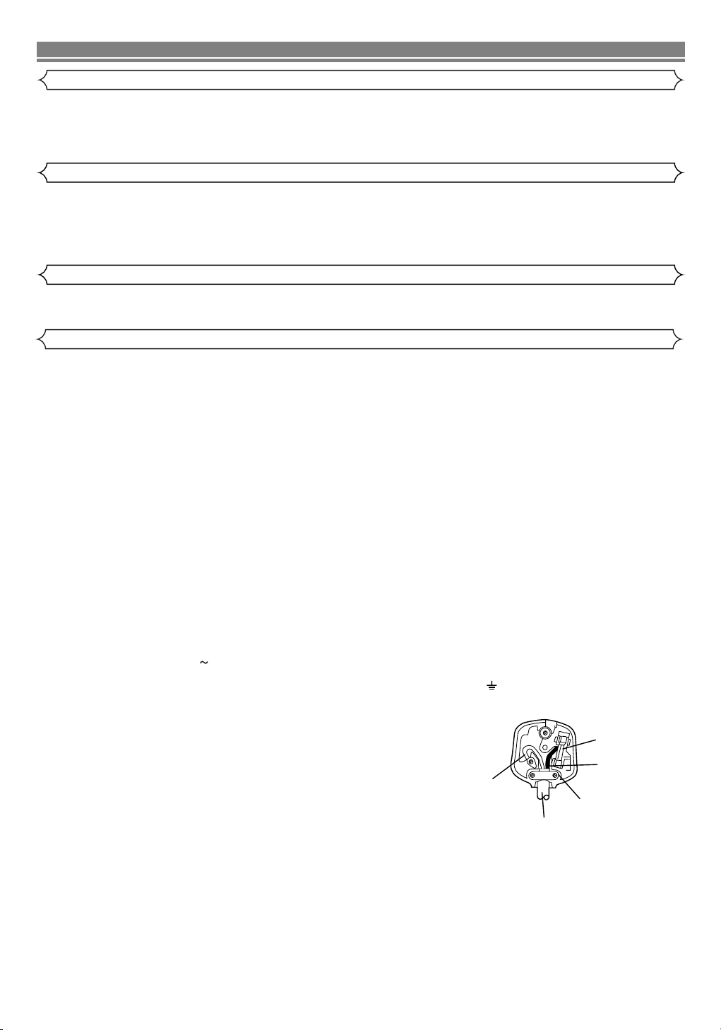
FUSE
BLUE
(Neutral)
BROWN
(Live)
CORD GRIP
OUTER SHEATH OF THE WIRE
Cabinet Cleaning
• Wipe the front panel and other exterior surfaces of the VCR with a soft cloth that has been immersed in lukewarm water and
wrung dry.
• Never use a solvent or alcohol. Do not spray insecticide liquid near the VCR. Such chemicals may cause damage and discolouration to the exposed surfaces.
Auto Head Cleaning
• This feature automatically cleans the heads as you insert or remove a cassette to ensure a clear picture.
• The playback picture may become blurred or interrupted even if the TV programme received is clear. This does not mean that
the recorded programme has been erased. This problem is caused by dirt accumulated on the head after long periods of use,
or usage of rental or old tapes. In this case, head cleaning requires highly technical expertise and the nearest dealer should
therefore be consulted. Clean heads only when problems occur.
Service
• Should your VCR become inoperative, do not try to correct the problem by yourself. There are no user-serviceable parts inside.
Tu rn the unit off, unplug the power cord, and take the unit to a Service Centre for servicing.
CONNECTION TO POWER
Before Switching on make sure that the voltage of your electricity supply is the same as that indicated on the rating plate.
Mains Cord
This appliance may be fitted with a non-rewireable plug. If it is necessary to change the fuse in a non-rewireable plug the fuse
cover must be refitted. If the fuse cover is lost or damaged, the plug must not be used until a replacement available from the appliance manufacturer is obtained.
It is important that the colour of the replacement fuse cover corresponds with the rating marking on the base of the plug.
If the plug has to be changed because it is not suitable for your socket, or becomes damaged, it should be cut off and an appro-
priate plug fitted following the wiring instructions below. The plug removed must be disposed of safely as insertion into a 13A socket is likely to cause an electrical hazard. For your own safety read the following instructions carefully before attempting to connect
this unit to mains.
The wires in this mains lead are coloured in accordance with the following code:
BLUE=NEUTRAL, BROWN=LIVE
Important
As the colours of the wires in the mains lead of this appliance may not correspond with the coloured markings identifying the terminals in your plug, proceed as follows:-
The wire which is coloured blue must be connected to the terminal which is marked with the letter N or coloured black.
The wire which is coloured brown must be connected to the terminal which is marked with the letter L or coloured red.
No connection is to be made to the earth terminal of the plug.
If a 13 Amp (BS 1363) Plug is used, a 3 Amp Fuse must be fitted, or if any other type of Plug is used a 3 or 5 Amp Fuse must be
fitted, either in the Plug or Adaptor, or on the Distribution Board.
Mains Supply: 220 - 240V 50 Hz - AC only
Do not make any connection to the larger pin marked with the letter “E” or by the symbol or coloured green or green and yellow.
3
EN
Page 4
DESCRIPTION OF CONTROLS
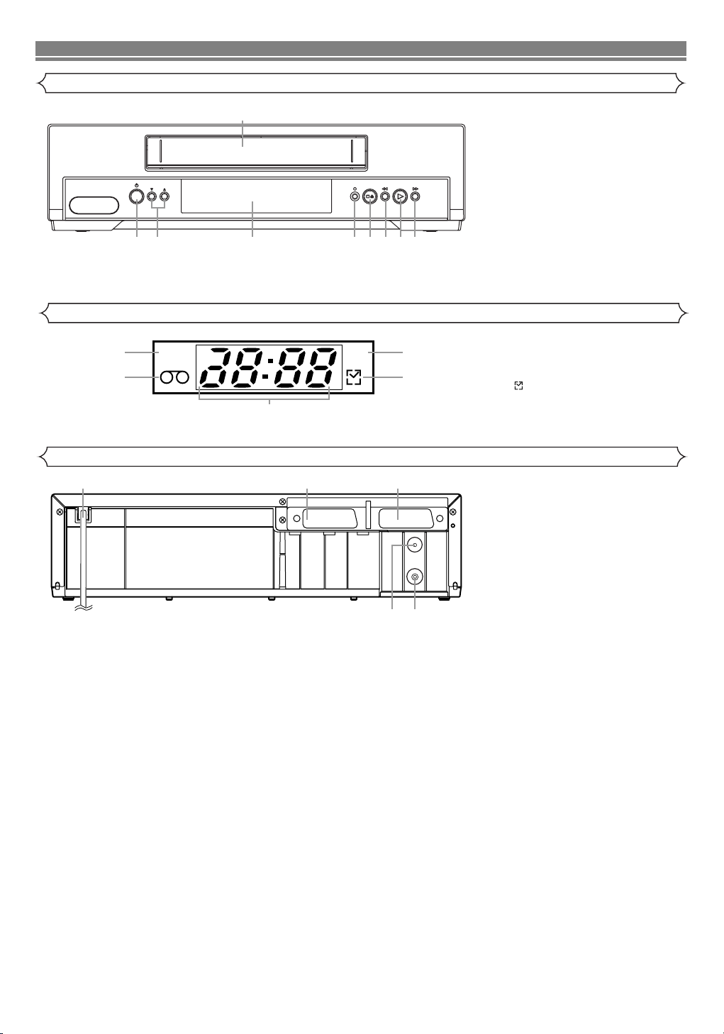
Front Panel
1
PROGRAM
TRACKING
Indicator
1. Cassette compartment
D (F.FWD) button
2.
B (PLAY) button
3.
4.
E (REW) button
CA(STOP/EJECT) button
5.
6. I ( REC/OTR) button
7. Indicator (See below)
8. PROGRAM (
o/p) [TRACKING]
buttons
9.y (OPERATE) button
247
35689
10
11
Rear Panel
15
PWR. REC
14
AV2(DECODER) AV1(TV)
12
13
10. PWR. (Power) indicator
11. TAPE IN indicator
12. REC indicator
13. (Timer) indicator
14. CLOCK indicator
1716
15. Power cord
16. AV2 (DECODER) socket
17. AV1 (TV) socket
18. RF OUT socket
19. AERIAL socket
AERIAL
RF OUT
1819
4
EN
Page 5
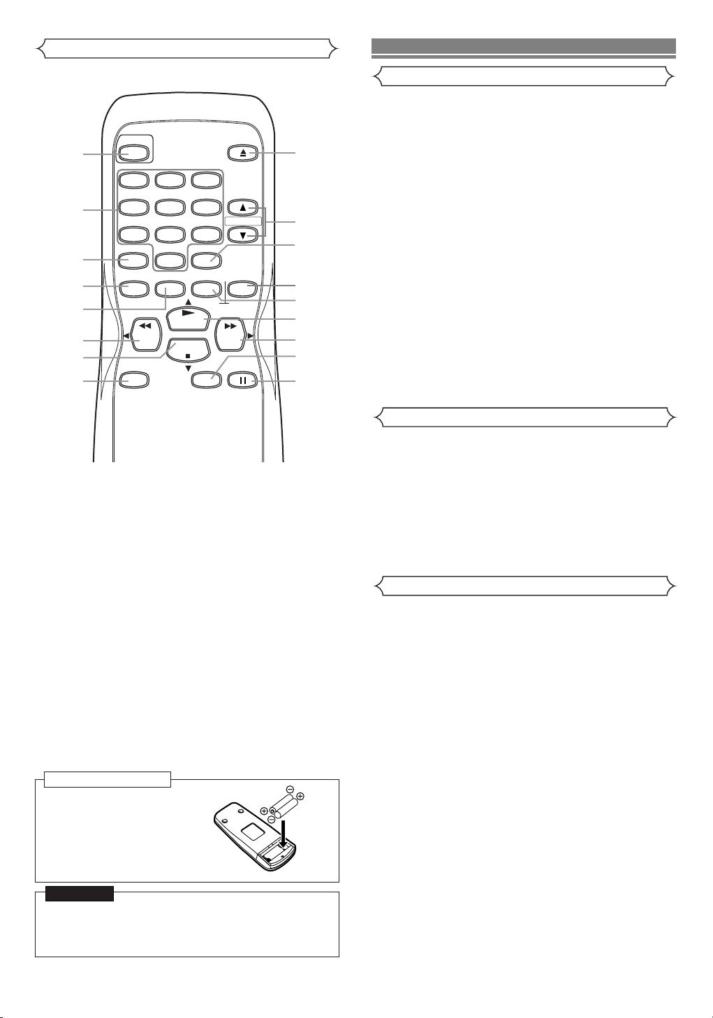
Remote Control
OPERATE
1
1
2
5
2
3
4
5
6
7
4
7
VIDEO Plus+
MENU
REW
REC/OTR
8
0
DISPLAY
PLAY
STOP
8
1. OPERATE button
2. NUMBER buttons
3. VIDEO Plus+ button
4. MENU button
5. DISPLAY button
6. REW/s button
7. STOP/Lbutton
8. REC/OTR button
9. PAUSE/STILL button
10. SPEED button
11. F.FWD/ B button
12. PLAY/o button
13. COUNTER RESET button
14. COUNTER MEMORY button
15. DAILY/WEEKLY button
16. PROGRAM (o/p) buttons
17. EJECT button
3
6
9
DAILY/WEEKLY
COUNTER
RESET
F.FWD
SPEED
EJECT
PROGRAM
MEMORY
PAUSE/STILL
17
16
15
14
13
12
11
10
9
SPECIFICATIONS
General Specifications
Television system: PAL I
TV standard
Video heads Rotary two-head
helical scan system
Tape width : 12.65mm
Tape speed
SP : 23.39mm/sec.
LP : 11.70mm/sec.
Tuner channel
IRA~IRJ
E21~E69
CATV
RF converter : Built-in UHF converter
Converter output : UHF Channel 22 to 69
(adjustable)
Timer indication : 24-hour system
Operating temperature : 5ºC ~ 40ºC
Te r minals
AERIAL : Coaxial type, male
RF OUT : Coaxial type, female
AUDIO/VIDEO : 21 pin scart socket x 2
Electrical Specifications
Video output level : 1Vp-p
Video output impedance : 75Ω unbalanced
Audio output level : -6dBv
Video input level : 0.5 ~2.0Vp-p
Audio input level : -10dBv
Video S/N ratio
(STANDARD): 45dB
Audio S/N ratio
(STANDARD): 41dB
Other Specifications
Power requirement : 220-240V ~ 50Hz
Power consumption : 25 Watts (Stand by: 3.5 watts)
Dimensions : W 360mm
H 92mm
D 226mm
Weight : 2.6 Kg. (approx.)
To insert the batteries:
Install two AA batteries
matching the polarity indicated inside the battery
compartment.
CAUTION
On Battery Replacement
• Do not mix old and new batteries. (Also never mix alkaline batteries with manganese batteries.)
• Designs and specifications are subject to change without notice.
5
EN
Page 6
CONNECTING THE VCR
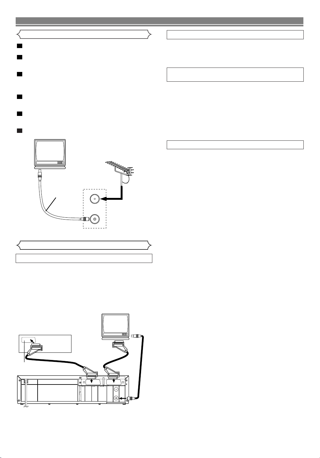
VCR to TV Connection
1
Disconnect the TV’s power cord from the AC outlet.
2
Disconnect the aerial from the back of your TV and connect it to the AERIAL socket on the back of the VCR.
3
Connect one end of the additional aerial lead supplied
with your VCR to the RF OUT socket on the back of the
VCR.
4
Connect the other end of the supplied aerial lead into the
aerial socket at the back of your TV.
5
For best results connect a Scart cable (not supplied). See
the diagram of “Other Connections”.
6
Plug the power cords of the VCR and TV into the AC outlets.
(TV)
UHF
to aerial socket
supplied
with VCR
AERIAL
to AERIAL
RF OUT
AV1 (TV) CONNECTION TO TV
If your TV has Scart sockets, you may connect your VCR’s
AV1 (TV) scart socket to the Scart socket on the back of
your TV. Please see the instruction manual for your TV.
AV2 (DECODER) CONNECTION FOR OTHER
EXTERNAL DEVICES
The second Scart socket AV2 (DECODER) is designated for
other external devices, e.g. decoder, another VCR, video
camera and so on.
NOTE:
• If you want to connect a TV with Scart socket to your VCR,
the TV must be connected to the VCR through AV1 (TV). A
connection to AV2 (DECODER) will not function correctly.
EXTERNAL INPUT MODE
To receive the signal from an external input (decoder, video
camera, another VCR etc.), connect to the AV2 (DECODER)
socket, and press the PROGRAM (o/p) buttons or enter
“002” with the NUMBER buttons to display “AV2” on the TV
screen.
If you use the AV1 (TV) socket, press the PROGRAM (o/p)
buttons or enter “001” with the NUMBER buttons to display
“AV1” on the TV screen.
to RF OUT
(Back of the VCR)
Other Connections
EURO SCART (AV) SOCKETS
Your VCR has two SCART sockets at the rear which can be
used to connect to the television and external devices e.g.
satellite decoders (Sky), digital terrestrial decoders
(Freeview), cable decoders (NTL, Telewest) or camcorders
and games consoles.
We recommend using SCART connections to obtain the
best quality picture and sound.
Decoder (Not supplied)
to 21-Pin Scart Jack
(TV)
to 21-Pin
Scart Jack
AV2(DECODER) AV1(TV)
AERIAL
RF OUT
to aerial
socket
to RF OUT
Euro Scart cables are obtainable at your dealer.
6
EN
Page 7
INITIAL SETUP
Video Channel Setting
• Use the remote control for this procedure.
1
Insert a pre-recorded tape into the VCR which has a film
or programme which you will recognise when it plays.
The VCR will turn on. Press the PLAY button to ensure
the tape is playing.
2
Tu rn your television to the preferred video channel (this
would normally be channel “0” for most makes of TV incl.
Hitachi - If in doubt consult your television instruction
book for details). Follow your television tuning instructions (as detailed in your TV instruction book) until you
can see the film or program playing on the VCR.
• When you can see the playback clearly, follow your television instructions to store the setting as the VCR playback channel and go to step .
• If you do not get a clear picture on playback and have
interference lines on the screen this can be caused by
the VCR broadcast frequency being too close to a television station frequency in your area. STEP will
explain how to change the RF output frequency.
3
Press the MENU button.
4
Press the PLAY/o or STOP/Lbutton repeatedly to
select “INITIAL” from the on screen menu. Then press
the F.FWD/B button.
5
Press the PLAY/o or STOP/Lbutton repeatedly to
select “RF OUT” from the on screen menu. Then, press
the F.FWD/B button.
• The RF OUT CH menu will appear on your TV screen.
6
Press the PLAY/o or STOP/Lbutton to select a
frequency which is not used for television broadcasts in
your area. You can select between RF CH 22 ~ RF CH
69, e.g. 51 or 53. (Your local dealer should be able to
advise you which channels to use if you are not sure)
7
Press the F.FWD/B button to store then the MENU button
to exit.
Follow the instructions in step above to tune your TV
to the new VCR frequency.
9
Press the
STOP
button to stop the tape.
NOTES:
• You may also access the RF OUT CH menu by pressing and
holding the MENU button on the remote control for 3 seconds
whilst the VCR is in STANDBY. (STANDBY = VCR plugged in
but switched off on the machine)
• If your VCR and TV are connected using a SCART cable the
RF converter may be switched off to avoid any possibility of
interference. To switch off the RF converter;
Follow step to step above and adjust the “RF OUT
CH” until it is 22 in step . Press the STOP/Lbutton so that
“- -” appears, instead of a number, next to “RF CH OUT”.
Press the F.FWD/
MENU
TIMER
SET UP
INITIAL
B button, then the MENU button to finish.
9
3
28
63
6
INITIAL
CH TUNING
CLOCK
RF OUT
Setting the Clock
This VCR incorporates a 24-hour clock. The clock must be set
for the Timer Recording function to operate correctly.
• Use the remote control for this procedure.
1
Press the MENU button.
2
Press the PLAY/
then press the F.FWD/
3
Press the PLAY/o or STOP/Lbutton to select “CLOCK”,
then press the F.FWD/
4
Press the PLAY/
AL” or “AUTO”, then press the F.FWD/B button.
• If you select “MANUAL”, continue with step .
• If you select “AUTO”, Auto Clock Setting becomes “ON”.
The clock time will appear automatically when you next
turn the VCR off and on.
5
Press the PLAY/
year appears, then press the F.FWD/
6
Press the PLAY/o or STOP/Lbutton until the relevant
month appears, then press the F.FWD/B button.
7
Press the PLAY/o or STOP/Lbutton until the relevant
day appears, then press the F.FWD/B button.
8
Press the PLAY/o or STOP/Lbutton until the relevant
hour appears, then press the F.FWD/B button.
9
Press the PLAY/o or STOP/Lbutton until the relevant
minute appears.
10
Press the MENU button to start the clock.
NOTES:
• Press the REW/s button to go one step back from the
current step during steps to .
•
Although seconds are not displayed, they begin counting
from 00 when you exit by pressing the MENU button. Use
this feature to synchronise the clock with the correct time.
• When unplugging the power-cord or if there is a power
failure for more than one minute, you may have to reset
the clock.
A
UTO CLOCK
•
Channel Presetting must be set before the Auto Clock is set.
• The VCR refers to the channel which was memorised into
position 01.
The PDC channel must therefore be set to position 01.
• The clock cannot be set automatically if you are not
receiving a channel that carries a time signal in your area.
In this case, set the clock manually.
• Once the auto clock setting is performed, the VCR will
correct the current time by receiving PDC broadcasts
whenever you turn off the VCR.
•
The VCR will correct the current time automatically at 8:00, if
the VCR’s power is turned off.
• Between 23:00~1:00, the AUTO CLOCK function does not
work even if the VCR’s power is turned off.
MENU
TIMER
SET UP
INITIAL
o or STOP/Lbutton to select “INITIAL”,
B button.
B button.
o or STOP/Lbutton to select “MANU-
5
o or STOP/Lbutton until the relevant
B button.
95
INITIAL
CH TUNING
CLOCK
RF OUT
RF OUT CH 35
CLOCK
YEAR 2 0 0 4
MONTH 0 1
DAY 0 7 WE
HOUR
MINUTE
7
_ _
_ _
EN
Page 8

TUNING
Tuning of broadcast channels not already preset in the VCR
can be performed in two ways.
AUTOMATIC TUNING
• By “AUTOMATICALLY” tuning channels and placing them
in sequential order in the VCR’s memory i.e. the first channel found will be memorised into the VCR’s channel position 1, the second channel found will be memorised into
the VCR’s channel position 2 and so on.
• Execution of the “Automatic” tuning cancels all the preset
channels. DO NOT use this feature if you intend to use
some of the pre-tuned channels. Use the “Manual” tuning
function to tune in the additional channels you require.
MANUAL TUNING
• Each channel is tuned manually and individually. Follow
the steps laid out in the “MANUAL TUNING” section.
Before you tune...
• It is necessary to set the video channel if your VCR is
connected to the TV via the coaxial cable, and TV channel
35 is employed for broadcasting, or interference lines
appear on the picture. Please refer to “Video Channel
Setting”.
Automatic Tuning
You can programme the tuner to scan all the channels you
can receive in your area. If you are using a Satellite receiver
turn it on and select SKY NEWS or a programme only available on Satellite before starting.
• Use the remote control for this procedure.
1
Tu rn on the TV and select the TV channel to the video
channel on the TV.
2
Press the MENU button.
3
Press the PLAY/o or STOP/Lbutton to select “INITIAL”,
then press the F.FWD/B button.
4
Press the PLAY/o or STOP/Lbutton to select “CH TUNING”, then press the F.FWD/B button.
5
Press the PLAY/o or STOP/Lbutton to select “AUTO”,
then press the F.FWD/B button.
• The tuner scans and memorises all the active channels in
your area. After scanning, the tuner stops on the lowest
memorised channel.
• Sorting of TV channels from P01 to P06 will be performed
automatically as follows.
P01: BBC1 P02: BBC2 P03: ITV
P04: CH4 P05: CH5 *(P06: SKY NEWS)
* If you are using a satellite receiver, turn it on and select
Sky News before commencing tuning.
MENU
TIMER
SET UP
INITIAL
scanning
INITIAL
CH TUNING
CLOCK
RF OUT
CH TUNING
AUTO
MANUAL
MOVE
To Select a Desired Channel
You can select a desired channel by using the PROGRAM
(o/p) buttons, or directly pressing the NUMBER buttons on
the remote control.
• Enter a channel numbers as a two-digit number for the
quickest results. For example, to select channel 6, press 0
and 6. If you only press 6, channel 6 will be selected after
a brief delay.
• You can only select channels 1–99.
Manual Tuning
• Use the remote control for this procedure.
1
Press the MENU button.
2
Press the PLAY/o or STOP/Lbutton to select “INITIAL”,
then press the F.FWD/B button.
3
Press the PLAY/o or STOP/Lbutton to select “CH TUNING”, then press the F.FWD/B button.
4
Press the PLAY/o or STOP/Lbutton to select “MANUAL”,
then press the F.FWD/B button.
5
Press the PLAY/o or STOP/Lbutton to select “POSITION”, then press the F.FWD/B button.
• When a weak signal is received in Manual Tuning mode,
you can change the background to solid blue or the static
screen by pressing the COUNTER RESET button.
6
Press the NUMBER, PLAY/o, or STOP/Lbutton to select
your desired position number, then press the F.FWD/B but-
ton.
•You can select position number 01-99.
• If [ON] appears on the right side of “SKIP”, press the
o or STOP/Lbutton to point to “SKIP”. Then, press
PLAY/
the F.FWD/B button to select [OFF].
•
If you want to remove scrambled signals, press the PLAY/o
or STOP/Lbutton repeatedly to point to “DECODER”. Then,
press the F.FWD/B button to select [ON].
7
Press the PLAY/o or STOP/Lbutton to select “CHANNEL”, then press the F.FWD/B button.
Press the PLAY/o or STOP/Lbutton. The VCR tuner will
begin to search up or down automatically. When a channel is found, the VCR will stop searching and the picture
will appear on the TV Screen.
•
You can select desired channel number by using
the
NUMBER buttons. You must refer to the following
Cannel Plan table and press three digits to select the
channel number. (To select channel 24, first press “0” button and then press “2” and “4”).
•
If this is the channel you want, press the F.FWD/B button.
Channel Plan
CH Indication TV Channel
01 – 10 IRA-IRJ, gap
21 – 69 E21 – E69
74 – 78 X, Y, Z, Z+1, Z+2
80 – 99, 100 S1 – S20, gap
121 – 141 S21 – S41
8
Press the MENU button to exit.
NOTE: To confirm that a channel has been
added, press the PROGRAM (o/p) buttons.
8
EN
Page 9

MENU
TIMER
SET UP
INITIAL
MANUAL
POSITION
CHANNEL
DECODER
SKIP
P08
008
[OFF]
[OFF]
INITIAL
CH TUNING
CLOCK
RF OUT
CH TUNING
AUTO
MANUAL
MOVE
To Skip a Preset Channel
The channels you can no longer receive or seldom watch
can be set to be skipped when you access channels with
the PROGRAM (o/p) buttons.
• Use the remote control for this procedure.
1
Press the MENU button.
2
Press the PLAY/o or STOP/Lbutton to select “INITIAL”,
then press the F.FWD/B button.
3
Press the PLAY/o or STOP/Lbutton to select “CH TUNING”, then press the F.FWD/B button.
4
Press the PLAY/o or STOP/Lbutton to select “MANUAL”,
then press the F.FWD/B button.
5
Press the PLAY/o or STOP/Lbutton to select “POSITION”, then press the F.FWD/B button.
6
Press the number,PLAY/
evant position number, then press the F.FWD/B button.
7
Press the PLAY/o or STOP/Lbutton to select “SKIP”,
then press the F.FWD/B button to select [ON].
•To memorise the channel again, press the F.FWD/B but-
ton. “ON” will change to “OFF”.
8
Press the MENU button to exit.
NOTE:To confirm that a channel has been deleted, press
the PROGRAM (o/p) buttons.
MENU
TIMER
SET UP
INITIAL
o, or STOP/Lbutton to select rel-
INITIAL
CH TUNING
CLOCK
RF OUT
Channel Order
The TV stations will normally be stored in the following
order: BBC1, BBC2, ITV, CH4 and CH5.
You can rearrange the order as follows.
• Use the remote control for this procedure.
1
Press the MENU button.
2
Press the PLAY/o or STOP/Lbutton to select “INITIAL”,
then press the F.FWD/B button.
3
Press the PLAY/o or STOP/Lbutton to select “CH TUNING”, then press the F.FWD/B button.
4
Press the PLAY/o or STOP/Lbutton repeatedly to select
“MOVE”, then press the F.FWD/B button.
5
Press the PLAY/o or STOP/Lbutton repeatedly to select
the position number you want to change the channel,
then press the F.FWD/B button.
•You cannot select a position number where “- - -” appears
next to the number. This is because SKIP is set to [ON] for
this position number.
• When a weak signal is received in Channel Order mode,
you can change the background to static blue by pressing
the COUNTER RESET button.
If you press the button again, the background will return to
the static screen.
6
Press the PLAY/
channel move to another position number, then press the
F.FWD/B button.
7
Press the MENU button.
MENU
TIMER
SET UP
INITIAL
MOVE
P01:
P02:
P03:
P04:
P05:
Position
Number
o or STOP/Lbutton repeatedly until the
INITIAL
CH TUNING
CLOCK
RF OUT
01
02
[ ]
03
04
05
P06:
06
P07:
07
P08:
08
P09:
09
P10:
10
Channel
Number
CH TUNING
AUTO
MANUAL
MOVE
MANUAL
POSITION
CHANNEL
DECODER
SKIP
P08
008
[OFF]
[ON]
CH TUNING
AUTO
MANUAL
MOVE
MOVE
P01:
P02:
P03:
P04:
P05:
P06:
P07:
P08:
P09:
P10:
[ ]
06
07
08
09
03
01
02
10
04
05
9
MOVE
P01:
P02:
P03:
P04:
P05:
P06:
P07:
P08:
P09:
P10:
06
07
08
09
03
01
02
10
04
05
EN
Page 10

BASIC OPERATION
Playback
Tracking Adjustment
• Tracking adjustment will be activated automatically (Digital
Tr acking function) when you start playback.
• When playing pre-recorded tapes or tapes recorded on
units other than your own, noise lines (black and white
streaks) may appear on the playback picture. If this occurs,
you can adjust the tracking control manually by pressing
the PROGRAM (
front panel until the streaks disappear. To return to the
DTR function, stop the tape once and start playback again.
1
Tu rn on the TV and select the video channel on the TV.
2
Insert a prerecorded tape.
The VCR will turn on automatically. If the erase-protection
tab has been removed, the VCR will start playback automatically.
3
Press the PLAY button to begin playback.
•Tracking adjustment will be activated automatically
(Digital Tracking function) when you start playback. To
adjust the tracking manually, press the PROGRAM
(o/p) buttons.
<If a tape is already in the VCR...>
• Using the buttons on the VCR
Just press the PLAY button on the VCR. Power will automatically turn on and playback will start. (Direct Button
Operation)
• Using the buttons on the remote control
Press the OPERATE button to turn on, and then press
the PLAY button.
4
Press the STOP button to stop playback.
1
During playback, press the F.FWD D or REW E button
to view a videotape at a high speed in either a forward or
reverse direction. In this mode, the sound will be muted.
2
Press the button again, the VCR will now search in super
high speed. (This function will not operate for a NTSC
tape.)
3
Press the PLAY button to return to normal playback.
Press the PAUSE/STILL button during playback to view a
still picture on the TV screen.
• When the picture begins to vibrate vertically, stabilize the
picture by pressing the PROGRAM (o/p) buttons. in the
Still mode.
• After the VCR has been in Still mode for 5 minutes, it will
stop automatically to protect the tape and the video head.
<Note for “Speed Search” and “Still Picture”>
• Usually there will be video “noise” lines (black and white
streaks or dots) on the screen. This is normal.
The still picture will, in addition to containing the “noise”
lines, be black and white.
This is not a fault of the machine but merely a by-product
of the technology involved in producing a VCR with LP
mode.
o/p) buttons on the remote control or
Speed Search
Still Picture
Recording
Viewing and Recording the same Programme
1
Insert a cassette tape with its erase-prevention tab in
place. (If necessary, rewind or fast forward the tape to the
point at which you want to begin recording.)
2
Press the NUMBER or PROGRAM (o/p) buttons to
select the channel to be recorded.
3
Press the SPEED button to select the tape speed
(SP/LP).
4
Press the REC/OTR button to begin recording.
• The REC indicator on the display comes on.
5
Press the STOP button when recording is completed.
Skipping unwanted Programme material
during Recording
1
Press the PAUSE/STILL button when you want to temporarily halt recording.
• You can check the remaining pause time with marks on
the TV screen. Each mark represents one minute. After
five minutes, the VCR will automatically switch to the Stop
mode to prevent tape damage.
2
Press the PAUSE/STILL or REC/OTR button to resume
recording.
Recording one Programme
while viewing another
You can record one programme while viewing another. To
start recording, follow steps to under “Viewing and
Recording the same Programme”. Then, set the TV to the
channel you want to watch.
To Monitor the progress of your Recording
Select the video channel on the TV.
Assemble Function
• You can record in continuation from previous programme
on a pre-recorded tape.
1
Insert a pre-recorded tape. Press the PLAY button to
start playback.
2
Press the PAUSE/STILL button at the desired point on
the tape.
3
Press the REC/OTR button. The VCR will be the
Recording Pause mode.
4
Press the PROGRAM (o/p) buttons to select the chan-
nel to be recorded .
5
Press
the REC/OTR or PAUSE/STILL button
will begin.
6
Press the STOP button when recording is completed.
41
. The recording
10
EN
Page 11

ADVANCED OPERATIONS
MENU
TIMER
SET UP
INITIAL
SET UP
AUTO REPEAT[ON
]
PICTURE[NORMAL
]
AUTO RETURN
[ON]
MENU
TIMER
SET UP
INITIAL
Counter Memory
This feature can be used to memorise a beginning point that
you want to watch again. Rewinding or fast forwarding
makes it easy to locate this point.
NOTES:
• If a tape includes programmes recorded in PAL and NTSC,
the Counter Memory function may not operate correctly.
• The COUNTER MEMORY button does not function if the
Auto Repeat mode is set to ON. In this case, set the Auto
Repeat mode to OFF.
1
Stop the tape at the desired point.
2
Press the COUNTER RESET button to display 0:00:00.
3
Press the COUNTER MEMORY button so that “M”
appears on the TV screen.
4
Press the REC/OTR or PLAY button.
• Press the STOP button when recording or playback is
completed.
5
Press the REW
E or F.FWD D button. The VCR will
automatically stop when the counter returns to 0:00:00
(approx.)
TO EXIT THE COUNTER MEMORY
Press the COUNTER MEMORY button so that “M” disappears from the TV screen.
NOTE: When you set the Auto Repeat mode to ON while
the Counter Memory mode is ON, the VCR exits the
Counter Memory mode automatically.
OTR (One Touch Recording)
This function enables you to set the duration of a recording
simply by pressing the REC/OTR button.
Follow steps to in “Viewing and Recording the
311
same Programme” section.
2
Press the REC/OTR button repeatedly until the desired
recording length appears in the upper left corner of the
TV screen.
• Recording stops when 0:00 is reached.
To check time remaining during an OTR
•
Press the DISPLAY button.
• To change the recording length during an OTR
Press the REC/OTR button repeatedly until the desired
length appears.
• To stop an OTR before recording is finished
Press the STOP button.
• To cancel the OTR but continue recording
Press the REC/OTR button repeatedly until “I” appears
without the recording length.
Auto Repeat Playback
The VCR has an auto repeat function that allows you to
repeat a tape indefinitely without touching the PLAY button.
• Use the remote control for this procedure.
• Insert a pre-recorded tape.
1
Press the MENU button.
2
Press the PLAY/
then press the F.FWD/B button.
3
Press the PLAY/o or STOP/Lbutton to select “AUTO
REPEAT”.
4
Press the F.FWD/B button so that “ON” appears next to
“AUTO REPEAT” on the TV screen.
When in Stop mode, Auto Repeat mode will start automatically.
If the on-screen menu still remains, press the MENU button to exit, then press the PLAY/o button.
o or STOP/Lbutton to select “SET UP”,
NOTES:
• Once you select the Auto Repeat mode, it stays in effect
even after you turn off VCR.
• COUNTER MEMORY does not function if the Auto Repeat mode
is set to ON.
• When you set the Auto Repeat mode to ON while the
Counter Memory mode is ON, the VCR exit the Counter
Memory mode automatically.
TO STOP PLAYBACK
Press the STOP button.
TO EXIT THE AUTO REPEAT MODE
Repeat steps to .Then, press the F.FWD/B button.
31
“OFF” will then appear next to “AUTO REPEAT” on the TV
screen. Press the MENU button to exit.
MENU
TIMER
SET UP
INITIAL
Picture Select
This function enables you to select the picture quality of a tape.
• Use the remote control for this procedure.
1
Press the MENU button.
2
Press the PLAY/
o or STOP/Lbutton to select “SET UP”,
then press the F.FWD/B button.
3
Press the PLAY/o or STOP/Lbutton to select “PICTURE”.
4
Press the F.FWD/B button until the desired mode (NORMAL, SOFT, or SHARP) is indicated on the TV screen.
5
Press the MENU button to exit.
NOTE:
• Once you select the Picture Select mode, it stays in effect
even after you turn off the VCR.
MENU
TIMER
SET UP
INITIAL
SET UP
AUTO RETURN
AUTO REPEAT[ON
PICTURE[NORMAL
11
[ON]
]
]
EN
Page 12

Automatic Operations
Automatic Rewind, Eject, Off
When the end of a tape is reached during recording, playback, or fast-forward, the tape will automatically rewind to
the beginning. After that, the VCR will eject the tape and
turn itself to off.
• The tape will not auto-rewind during timer recording or One
Touch Recording.
• When the Counter Memory is activated, the tape will
rewind to the M0:00:00 position and the VCR will enter the
Stop mode.
Tape Eject
A tape can be ejected with the VCR power on or off (but the
VCR must be plugged in).
• If a timer recording is set, a tape can only be ejected with
the power on.
Real Time Tape Counter
• This shows the elapsed recording or playback time in
hours, minutes, and seconds. (Nothing is shown in the
case of blank portion)
• The “ – ” indication will appear when the tape is rewound
further than the tape counter position “0:00:00”.
Timer Recording
You may program the VCR to start and end a recording while
you are away. You can set eight programmes to record on
specific days, daily or weekly within a 1 year period.
• Use the remote control for this procedure.
• Insert a cassette tape with its erase-prevention tab in
place. (If necessary, rewind or fast forward the tape to the
point at which you want to begin recording.)
1
Press the MENU button.
2
Press the PLAY/
then press the F.FWD/B button.
NOTES: If you have not set the clock yet, “CLOCK” setting
menu appears. If so, follow the steps outlined in the “Setting
the Clock” section. Then, set the timer.
• When you press the F.FWD/B button after pressing the
PLAY/o or STOP/Lbutton during steps to ,the input
mode will move to the next step.
•
If you do not press the F.FWD/B button within 5 seconds of
setting an item, the input mode will move to the next step.
• Press the REW/s button to go back one step from the cur-
rent setting during steps to . If the REW/s button is
pressed when the TIMER NUMBER is flashing, the entire
programme contents will be erased.
3
Programme number flashes. Press the PLAY/
STOP/Lbutton repeatedly until the desired programme
number appears. Then, press the F.FWD/B button.
4
• For once-only recording : Press the PLAY/o or STOP/
button repeatedly until the relevant month appears.
• For daily recording : To record a TV programme at the
same time on the same channel from Monday through
Friday. While the month digit is flashing, press the PLAY/o
or STOP/Lbutton repeatedly to select “MO-FR”.
• For everyday recording : To record a TV programme at
the same time on the same channel every day. While the
month digit is flashing, press the PLAY/o or STOP/Lbutton
repeatedly to select “MO-SU”.
• For weekly recording : To record a TV programme at the
same time on the same channel every week. While the
month digit is flashing, press the PLAY/o or STOP/Lbutton
repeatedly to select “W-MO” (Example: every monday).
o or STOP/Lbutton to select “TIMER”,
93
10
4
o or
L
5
For once-only recording only : Press the PLAY/o or
STOP/Lbutton repeatedly until your desired day
appears.
6
Press the PLAY/o or STOP/Lbutton repeatedly until the
relevant start hour appears. Next, enter the minute digit.
7
Press the PLAY/o or STOP/Lbutton repeatedly until the
relevant end hour appears. Next, enter the minute digit.
8
Press the PLAY/o or STOP/Lbutton repeatedly until the
relevant channel number appears.
9
Press the PLAY/o or STOP/Lbutton repeatedly until your
the desired tape speed appears.
10
Press the PLAY/o or STOP/Lbutton repeatedly to set
PDC “ON” or “OFF”.
11
Press the F.FWD/B button. Programme 1 is now completed.
11
•To set another timer programme, repeat steps to .
12
Press the MENU button to exit.
13
Press the OPERATE button to activate the timer.
3
The indicator on the display comes on.
MENU
TIMER
SET UP
INITIAL
O STOP A TIMER PROGRAMME WHICH HAS ALREADY
T
ST
ARTED
TIMER NUMBER
DATE
START
END
CHANNEL
SPEED
PDC
1
--/--
--:--
--:--
--
--
--
Press theCA(STOP/EJECT) button on the VCR.
NOTE: The STOP/Lbutton on the remote control will not
function in the Timer Recording mode.
TO CORRECT TIMER PROGRAMMES
If you want to correct an automatic timer after you finished
setting programme,
Repeat steps to in the “Timer Recording” section.
2
Select the setting you want to change using the F.FWD/B
311
or REW/s button.
3
Enter the correct numbers using the PLAY/
o or STOP/
button, then press the F.FWD/B button.
4
Press the MENU button to exit.
5
Press the OPERATE button to return to timer stand-by
mode.
TO CANCEL OR CHECK THE START/END TIME
Repeat steps to in the “Timer Recording”.
2
Select a programme number you want to check using the
o or STOP/Lbutton. The details of selected pro-
PLAY/
211
gramme appears on the TV screen.You may cancel the
entire programme by pressing the REW/s button.
3
Press the MENU button to exit.
AVOID OVERLAP OF TIMER PROGRAMMES ...
A timer programme will not work while another programme
is under execution.
Programme 1
Programme 2
Programme 3
9:00 10:00 11:00
L
12
EN
Page 13

Hint for Timer Recording
• If there is a power failure or the VCR is unplugged for more
than 1 minute, the clock setting and all timer settings will be
lost.
• If the tape runs out before the end time, the VCR will switch
to the Stop mode immediately, eject the tape and the VCR
power will be turned off. The indicator will flash.
• If a tape is not in the VCR, timer recording cannot be per-
formed and the indicator flashes. If an erase-prevention
tab of the tape is missing, the tape will be ejected and the
indicator will flash. Please insert a recordable tape.
• When all the Timer Recordings are completed, the indicator also flashes. To play or eject the recorded tape,
press the OPERATE button first, and then press the
PLAY or EJECT button.
• The TV that is connected to your VCR may be turned on or
off when the VCR is in the Timer-recording mode.
• The VCR will only perform a timer recording after it has been
placed into standby mode.
5
Press
the PLAY/o or STOP/Lbutton
repeatedly until the
desired tape speed appears.
6
Press
the PLAY/o or STOP/Lbutton
to set PDC “ON” or
“OFF”.
7
Press the MENU button to exit.
8
Press the OPERATE button to activate the timer.
The indicator on the display comes on.
VIDEO Plus+ system
PlusCode No.
---------
VIDEO Plus+ system
PlusCode No.
123456789
Timer Recording Using the VIDEO Plus+®System
You can programme the timer using the PlusCode numbers
that are printed in TV guide magazine.You can set eight programmes to record.
• Use the remote control for the this procedure.
• Insert a cassette tape with its erase-prevention tab in
place. (If necessary, rewind or fast forward the tape to the
point at which you want to begin recording.)
1
Press the VIDEO Plus+ button.
NOTE: If you have not set the clock yet, the “CLOCK” setting menu will appear. If this happens, follow the instructions
in the “Setting the Clock” section. After the clock has been
set you may continue with step .
2
Enter the PlusCode number
for the programme you want to record by using the
number buttons (0~9) on your remote control.
• If you make a mistake whilst entering the PlusCode num-
ber you can erase each digit in turn by pressing the
REW/s button.
3
For a once off recording press the VIDEO Plus+ button.
• If you want to repeat this recording on a daily or weekly
basis then select one of the following options before pressing the VIDEO Plus+ button.
•
FOR DAILY RECORDING: To record a TV programme at
the same time on the same channel, from Monday to Friday.
• Press the DAILY/WEEKLY button repeatedly to select
“DAILY (MO-FR)”, then press the VIDEO Plus+ button.
•
FOR EVERYDAY RECORDING: To record a TV programme
at the same time on the same channel every day.
• Press the DAILY/WEEKLY button repeatedly to select
“DAILY (MO-SU)”, then press the VIDEO Plus+ button.
• FOR WEEKLY RECORDING: To record a TV programme
at the same time on the same channel every week.
•
Press
the DAILY/WEEKLY button
“WEEKLY”, then press
NOTES:
• If the PlusCode number is not available, it will be cleared
automatically when you press the VIDEO Plus+ button.
Enter the correct PlusCode number and press the VIDEO
Plus+ button again.
• If the PlusCode number flashes when you press the
VIDEO Plus+ button, this means that the PlusCode number you entered was incorrect or the timer recording you
just programmed and another timer recording overlap.
4
Confirm the channel number, then, press the F.FWD/B
button.
• If your local channel information is programmed in VCR’s
memory, your local channel number appears automatically.
• If your local channel information is not programmed in VCR’s
memory, “– –” or an incorrect channel number may appear.
In this case, press the PLAY/o or STOP/Lbutton repeatedly
until your desired channel number appears. Then, press the
F.FWD/
B button.
• When you select the channel number using the PLAY/
STOP/Lbutton, it memorises in VCR’s memory.
2
repeatedly to select
the VIDEO Plus+ button
.
o or
TIMER NUMBER
DATE
START
END
CHANNEL
SPEED
PDC
TIMER NUMBER
DATE
START
END
CHANNEL
SPEED
PDC ON
1
06
19:30
20:30
16
SP
/
05 SA
TIMER NUMBER
DATE
START
END
CHANNEL
SPEED
PDC
PDC (Programme Delivery Control)
The PDC system looks for the start signal several hours
before published start time and for several hours afterwards.
This means that if the programme is broadcast anytime during this period it will be recorded correctly.
Please note that if you have set an incorrect TIMER setting, it
will stay in the memory until you cancel it (see page 12 for
details on how to cancel a programme).
Auto Return
When timer recording is finished, the VCR will automatically
rewind the tape to the beginning where it started recording. If
there are any remaining programmes including Daily,
Everyday, & Weekly, AUTO RETURN will not operate.
1
Press the MENU button
2
Press
the PLAY/o or STOP/Lbutton
to “SET UP”, then press the
3
Press
the PLAY/o or STOP/Lbutton
RETURN”, then press the
.
F.FWD/B button
F.FWD/B button
repeatedly to point
.
to point to “AUTO
.
[ON] will appear next to “AUTO RETURN”.
4
Press the MENU button.
W
ATCH THE RECORDED TIMER PROGRAMME
Press the OPERATE button to turn on the VCR, then press
the PLAY button.
13
1
06
19:30
20:30
16
SP
OFF
1
06
19:30
20:30
16
SP
OFF
/
05 SA
/
05 SA
EN
Page 14

■
SP
0:12:34
■
SP
17:40
P02
<CLOCK and CHANNEL
NUMBER mode>
<COUNTER mode>
Press once. Press once.
Press once.
<OFF mode>
RF OUT
AERIAL
AV2(DECODER) AV1(TV)
to RF OUT
to aerial
socket
[Source (Playing) VCR <Monaural>]
(another VCR)
to 21-Pin
Scart Jack
[TV set]
(Use for monitoring)
[Editing (Recording) VCR]
(this unit)
Coaxial cable (supplied)
Parents Lock
Parents Lock prevents use of the VCR by making the VCR feature buttons on the VCR and the remote control inoperative.
• The “PWR.” indicator on the display comes on.
1
Press and hold down the OPERATE button on the remote
control for 5 seconds until “PL” appears on the display.
The Parents Lock is activated.
When you want to cancel it, press and hold the OPERATE
button on the remote control again for 5 seconds.
When Parents Lock is activated:
• The time will appear on the display. “P.L.” will appear on the
display for two seconds every minute.
• You may insert a tape. However, the VCR power will
remain off.
• You may press the EJECT button to remove the tape
(unless a timer recording is programmed or has finished.)
• Timer recording will take place as scheduled, even if
Parents Lock is activated. “P.L.” will appear steadily on the
TV screen during the timer recording.
Copying a Video Tape
You can make copies of videotapes made by friends or relatives for your own enjoyment.
WARNING: Unauthorized recordings of copyrighted
video tapes may be an infringement of copyright laws.
Connect the recording VCR (this unit), playing VCR (another
VCR) and your TV as outline in the following diagram.
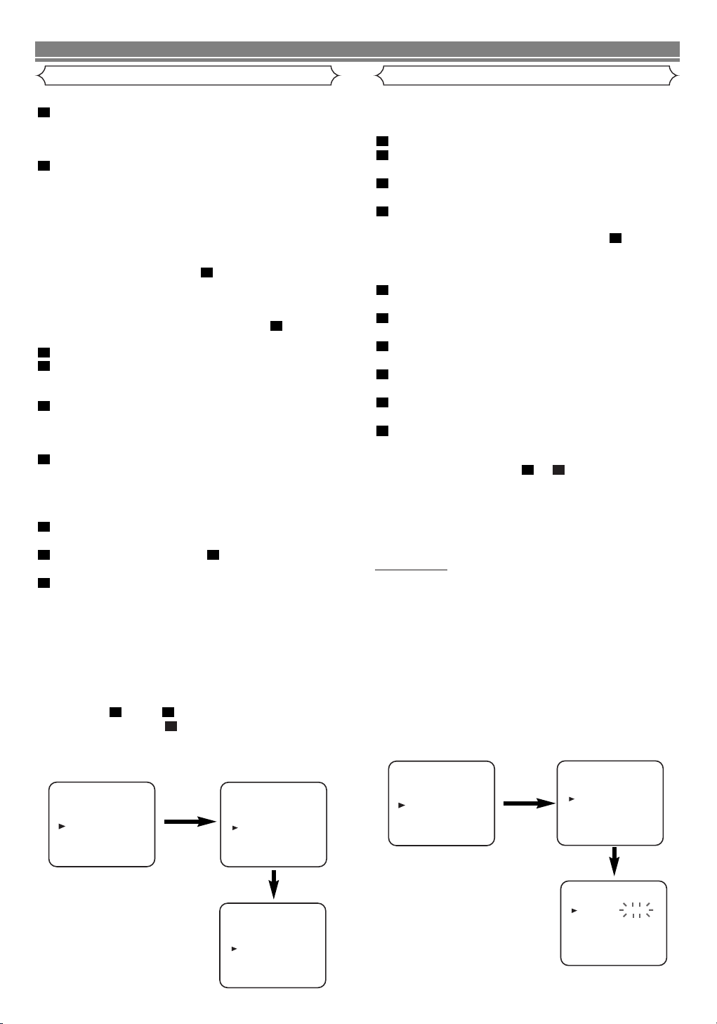
A Status Display
• To check the Counter, or Clock & Channel number,
press the DISPLAY button. Each time you press the DISPLAY button, TV screen will change as illustrated:
When you select the channel using the remote control
NUMBER buttons, select the desired channel
(position number).
Video Cassette Tape
This VCR will operate with any cassette that bears the VHS
mark. For best results, we recommend the use of high-quality tapes. Do not use poor quality or
damaged tapes.
• You can prevent accidental erasing of
a recording by breaking off the eraseprevention tab on the back edge of
the cassette.
• If you decide to record on the tape again, cover the hole
with plastic tape.
Ta b
1
Insert a pre-recorded video cassette into the playing VCR.
2
Insert a blank video cassette, or one you want to record
over, into the cassette compartment of the recording VCR.
3
Press the SPEED button on the remote control to select
the desired recording speed (SP/LP).
4
Select “AV2” position on the recording VCR. See “Other
Connections”.
5
Press the I (REC/OTR) button on the recording VCR.
6
Begin playback of the tape in the playback VCR.
7
To stop recording, press the CA(STOP/EJECT) button
on the recording VCR, then stop playback of the tape in
the playing VCR.
NOTES:
• For best results during dubbing, use the VCR’s front panel
controls whenever possible. The remote control might
affect the playback VCR’s operation.
• If video or colour fades in and out, you may be copying a
copy guarded video tape.
Tu rn on the TV and select the video channel on the TV.
To Monitor the Recording
Two Different Tape Speeds
Before recording, select the tape speed : SP mode
(Standard Play) or LP mode (Long Play).
The table below shows the maximum recording/playback
time using E-60, E-120, E-180 or E-240 tapes in each
mode.
TYPE OF TAPE RECORDING/PLAYBACK TIME
TAPE SPEED
SP MODE LP MODE
E-60 1 HOUR 2 HOURS
E-120 2 HOURS 4 HOURS
E-180 3 HOURS 6 HOURS
E-240 4 HOURS 8 HOURS
TV Colour System
Different countries use different television colour systems.
Tapes recorded in the PAL or NTSC system can be played
back on this unit. Usually, the picture on the TV screen will
be in black and white when you play back a tape that is
recorded in a different colour system.
• Tapes recorded in the NTSC system can be played back
on this unit and a PAL system TV set. This feature is only
available in the SP mode. When playing back such tapes,
the picture may roll up or down, shrink vertically and black
bars may appear both at the top and bottom of the screen.
Adjust the vertical hold control on your TV, if the TV features this control.
EN
14
Page 15

TROUBLESHOOTING GUIDE
If you have followed the instructions contained in this manual and have difficulty in operating your VCR, locate the SYMPTOM in
the left column below. Check the corresponding cell CORRECTIVE ACTION columns to remedy the problem.
SYMPTOM CORRECTIVE ACTION
No power. • Make sure the power cord is connected to an AC outlet.
• Make sure the power is turned on.
Timer recording is not possible.
Recording mode cannot be
engaged.
No picture or poor picture
on playback.
No picture but the audio is
OK in playback.
Playback picture is partially
noisy.
On-the-air TV programmes
cannot be seen.
No operation by infrared
Remote Control.
Video or colour fades in
and out when making a
copy of a video tape.
Make your contribution to the environment!!!
• Spent batteries do not belong in the dustbin.
• You can dispose of them at a collection point for spent batteries or special waste.
Contact your council for details.
• Make sure the timer recording is set correctly.
• Make sure the power is off.
• Make sure the VCR clock is set correctly.
• Make sure
tab with adhesive tape.
• Set your TV to the video channel.
• Fine tune your TV.
• Head cleaning is necessary, consult the nearest Authorized Service Centre.
• Adjust tracking control for a better picture by using the PROGRAM (o/p) buttons.
• Re-check the AERIAL and RF OUT connections.
• Set your TV to the TV channel correctly.
• Check the batteries in the remote control.
• You cannot copy a copyrighted video tape. You are experiencing copy guard protection.
the erase-prevention tab on the tape is intact. If removed, cover the hole after the
15
EN
Page 16

16
EN
Page 17

SOME DO’S AND DON’TS ON THE SAFE USE OF EQUIPMENT
This equipment has been designed and manufactured to meet international safety standards but like any electrical
equipment, care must be taken if you are to obtain the best results and safety is to be assured.
★★★★★★★★★★★
DO read the operating instructions before you attempt to use the equipment.
DO ensure that all electrical connections (including the mains plug, extension leads and interconnections between
pieces of equipment) are properly made and in accordance with the manufacturer’s instructions.
Switch off and withdraw the mains plug when making or changing connections.
DO consult your dealer if you are ever in doubt about the installation, operation or safety of your equipment.
DO be careful with glass panels or doors on equipment.
★★★★★★★★★★★
DON’T continue to operate the equipment if you are in any doubt about it working normally, or if it is damaged in
any way switch off, withdraw the mains plug and consult your dealer.
DON’T remove any fixed cover as this may expose dangerous voltages.
DON’T leave equipment switched on when it is unattended unless it is specifically stated that it is designed for
unattended operation or has a standby mode. Switch off using the switch on the equipment and make sure that
your family know how to do this. Special arrangements may need to be made for infirm or handicapped people.
DON’T use equipment such as personal stereos or radios so that you are distracted from the requirements of
traffic safety. It is illegal to watch television whilst driving.
DON’T listen to headphones at high volume, as such use can permanently damage your hearing.
DON’T obstruct the ventilation of the equipment, for example with curtains or soft furnishings.
Overheating will cause damage and shorten the life of the equipment.
DON’T use makeshift stands and NEVER fix legs with wood screws — to ensure complete safety always fix the
manufacturer’s approved stand or legs with the fixings provided according to the instructions.
DON’T allow electrical equipment to be exposed to rain or moisture.
ABOVE ALL
--- NEVER let anyone especially children push anything into holes, slots or any other opening in the
case — this could result fatal electrical shock:
--- NEVER guess or take chances with electrical equipment of any kind.
--- it is better to be safe than sorry!
★★★★★★★★★★★
17
EN
Page 18

MEMO
18
EN
Page 19

MEMO
19
EN
Page 20

DECLARATION OF CONFORMITY
EMC-Directive: 89 / 336 / EEC
Low Voltage Directive: 73 / 23 / EEC
CE- Marking: 93 / 68 / EEC
We: HITACHI EUROPE LTD.
Whitebrook Park
Lower Cookham Road
Maidenhead
Berkshire
SL6 8YA
declare that the Video Cassette Recorder
VT-MX410E(UK)
is in compliance with following norms:
EN 55013: 2001
EN 55020: 2002
EN 61000-3-2: 2000
EN 61000-3-3: 1995 + A1: 2001
EN 60065: 1998
HITACHI - YOUR GUARANTEE (UK & Ireland)
For the period of 12 MONTHS from the date of purchase your product has the benefit of our FULL PARTS AND LABOUR
GUARANTEE as detailed below.
We undertake to replace of repair any part of the product which fails due to a manufacturing defect within 12 months of the date
of purchase provided that.
1) The product has been installed and used only in accordance with the instructions supplied with the product.
2) The product has not been repaired maintained, or modified by any person other than our authorised Engineer.
3) The product serial number is not removed or altered.
This guarantee does not apply to products acquired second-hand or for commercial or communal use.
This guarantee does not extend to user control adjustments, battery replacement and aerial adjustment. Any parts replaced
under guarantee shall become the property of HITACHI EUROPE LTD.
Please note that evidence of the date of purchase will be required before service under guarantee is carried out.
This guarantee does not affect your statutory rights. In all cases of difficulty consult your HITACHI dealer.
HITACHI EUROPE LTD.
Whitebrook Park
Lower Cookham Road
Maidenhead
Berkshire
SL6 8YA
Tel: 01628 643000
Fax: 01628 643400
Email: consumer-ser
vice@hitachi-eu.com
www.hitachi-consumer-eu.com
EN
Page 21

Hitachi, Ltd. Tokyo, Japan
International Sales Division
THE HITACHI ATAGO BUILDING,
No. 15 –12 Nishi Shinbashi, 2 – Chome,
Minato – Ku, Tokyo 105-8430, Japan.
Tel: 03 35022111
HITACHI EUROPE LTD,
Whitebrook Park
Lower Cookham Road
Maidenhead
Berkshire
SL6 8YA
UNITED KINGDOM
Tel: 01628 643000
Fax: 01628 643400
Email: consumer-service@hitachi-eu.com
HITACHI EUROPE GmbH
Munich Office
Dornacher Strasse 3
D-85622 Feldkirchen bei München
GERMANY
Tel: +49-89-991 80-0
Fax: +49-89-991 80-224
Hotline: +49-180-551 25 51 (12ct/min)
Email: HSE-DUS.service@hitachi-eu.com
HITACHI EUROPE srl
Via Tommaso Gulli N.39, 20147
Milano, Italia
ITALY
Tel: +39 02 487861
Tel: +39 02 38073415 Servizio Clienti
Fax: +39 02 48786381/2
Email: customerservice.italy@hitachi-eu.com
HITACHI EUROPE S.A.S
Lyon Office
B.P. 45, 69671 BRON CEDEX
FRANCE
Tel: +33 04 72 14 29 70
Fax: +33 04 72 14 29 99
Email: france.consommateur@hitachi-eu.com
HITACH EUROPE AB
Egebækgård
Egebækvej 98
DK-2850 Nærum
DENMARK
Tel: +45 43 43 6050
Fax: +45 43 60 51
Email: csgnor@hitachi-eu.com
Hitachi Europe Ltd
Bergensesteenweg 421
1600 Sint-Pieters-Leeuw
BELGIUM
Tel: +32 2 363 99 01
Fax: +32 2 363 99 00
Email: sofie.van.bom@hitachi-eu.com
www.hitachidigitalmedia.com
HITACHI EUROPE S.A.
364 Kifissias Ave. & 1, Delfon Str.
152 33 Chalandri
Athens
GREECE
Tel: 1-6837200
Fax: 1-6835964
Email: service.hellas@hitachi-eu.com
HITACHI EUROPE S.A.
Gran Via Carlos III, 86, planta 5
Edificios Trade - Torre Este
08028 Barcelona
SPAIN
Tel: +34 93 409 2550
Fax: +34 93 491 3513
Email: atencion.cliente@hitachi-eu.com
HITACHI Europe AB
Box 77 S-164 94 Kista
SWEDEN
Tel: +46 (0) 8 562 711 00
Fax: +46 (0) 8 562 711 13
Email: csgswe@hitachi-eu.com
HITACHI EUROPE LTD (Norway) AB
STRANDVEIEN 18
1366 Lysaker
NORWAY
Tel: 67 5190 30
Fax: 67 5190 32
Email: csgnor@hitachi-eu.com
HITACHI EUROPE AB
Neopoli / Niemenkatu 73
FIN-15140 Lahti
FINLAND
Tel : +358 3 8858 271
Fax: +358 3 8858 272
Email: csgnor@hitachi-eu.com
HITACHI EUROPE LTD
Na Sychrove 975/8
101 27 Pr aha 10 – Bohdalec
CZECH REPUBLIC
Tel: +420 267 212 383
Fax: +420 267 212 385
Email: csgnor@hitachi-eu.com
 Loading...