

SERVICE MANUAL
TK No. 5301E
VT-FX795A
SPECIFICATIONS AND PARTS ARE SUBJECT TO CHANGE FOR IMPROVEMENT
VIDEO CASSETTE RECORDER
March 2003
Digital Media Division, Tokai

CONTENTS
1 SAFETY PRECAUTION FOR REPAIR
REPAIR . . . . . . . . . . . . . . . . . . . . . . . . . . . . . . . .1-1
1-1 IMPORTANT SAFETY PRECAUTIONS . . . . . . . . . 1-1
1-1-1 Product Safety Notice . . . . . . . . . . . . . . . . . . . . . 1-1
1-1-2 Precautions during Servicing . . . . . . . . . . . . . . . 1-1
1-1-3 Safety Check after Servicing . . . . . . . . . . . . . . . . 1-2
1-2 STANDARD NOTES FOR SERVICING . . . . . . . . . . 1-3
1-2-1 Circuit Board Indications . . . . . . . . . . . . . . . . . . . 1-3
1-2-2 Instructions for Connectors . . . . . . . . . . . . . . . . . 1-3
1-2-3 How to Remove/Install Flat Pack-IC . . . . . . . . . . 1-3
1-2-4 Instructions for Handling Semi-conductors . . . . . 1-5
2 GENERAL DESCRIPTION . . . . . . . . . . . . . . . . .2-1
2-1 SPECIFICATIONS . . . . . . . . . . . . . . . . . . . . . . . . . . 2-1
2-2 COMPARISON OF MODELS. . . . . . . . . . . . . . . . . . 2-2
2-2-1 Comparison of Features . . . . . . . . . . . . . . . . . . . 2-2
2-2-2 Comparison of Main Control ICs. . . . . . . . . . . . . 2-2
2-3 FUNCTION INDICATOR SYMBOLS . . . . . . . . . . . . 2-3
2-4 OPERATING CONTROLS AND FUNCTIONS. . . . . 2-4
3 TROUBLESHOOTING. . . . . . . . . . . . . . . . . . . . .3-1
3-1 TROUBLESHOOTING . . . . . . . . . . . . . . . . . . . . . . . 3-1
3-2 STANDARD MAINTENANCE. . . . . . . . . . . . . . . . . . 3-5
3-2-1 Service Schedule of Components. . . . . . . . . . . . 3-5
3-2-2 Cleaning . . . . . . . . . . . . . . . . . . . . . . . . . . . . . . . 3-6
4 ADJUSTMENT . . . . . . . . . . . . . . . . . . . . . . . . . .4-1
4-1 PREPARATION FOR SERVICING. . . . . . . . . . . . . . 4-1
4-1-1 How to Enter the Service Mode. . . . . . . . . . . . . . 4-1
4-2 FIXTURE AND TAPE FOR ADJUSTMENT . . . . . . . 4-2
4-2-1 How to Use The Fixtures And Tape. . . . . . . . . . . 4-2
4-3 ELECTRICAL ADJUSTMENT INSTRUCTIONS . . . 4-3
4-3-1 Test Equipment Required . . . . . . . . . . . . . . . . . . 4-3
4-3-2 Head Switching Position Adjustment . . . . . . . . . 4-3
4-4 MECHANICAL ALIGNMENT PROCEDURES . . . . . 4-4
4-4-1 Service Information . . . . . . . . . . . . . . . . . . . . . . . 4-4
4-4-2 Tape Interchangeability Alignment . . . . . . . . . . . 4-5
1-A. Preliminary/Final Checking and
Alignment of Tape Path . . . . . . . . . . . . . . . . . . . . 4-6
1-B. X Value Alignment. . . . . . . . . . . . . . . . . . . . . . . . 4-6
1-C. Checking/Adjustment of Envelope Waveform . . . 4-7
1-D. Azimuth Alignment of
Audio/Control/Erase Head. . . . . . . . . . . . . . . . . . 4-7
6 EXPLODEDS VIEWS AND PARTS LIST . . . . . 6-1
6-1 EXPLODED VIEWS . . . . . . . . . . . . . . . . . . . . . . . . .6-1
6-1-1 Cabinet Section. . . . . . . . . . . . . . . . . . . . . . . . . . .6-1
6-1-2 Deck Mechanism View 1 Section . . . . . . . . . . . . .6-2
6-1-3 Deck Mechanism View 2 Section . . . . . . . . . . . . .6-3
6-1-4 Deck Mechanism View 3 Section . . . . . . . . . . . . .6-4
6-2 REPLACEMENT PARTS LIST. . . . . . . . . . . . . . . . . .6-5
6-2-1 Mechanical Parts List . . . . . . . . . . . . . . . . . . . . . .6-5
6-2-2 Electrical Parts List . . . . . . . . . . . . . . . . . . . . . . . .6-7
SCHEMATIC, CIRCUIT BOARD AND BLOCK
DIAGRAMS
1 SCHEMATIC DIAGRAMS/CBA’S AND TEST POINTS . 1
2 WIRING DIAGRAMS. . . . . . . . . . . . . . . . . . . . . . . . . . . . 3
3 SCHEMATIC DIAGRAMS . . . . . . . . . . . . . . . . . . . . . . . . 4
3-1 Main 1/5 Schematic Diagram. . . . . . . . . . . . . . . . . . . . 4
3-2 Main 2/5 & Sensor Schematic Diagrams. . . . . . . . . . . 5
3-3 Main 3/5 Schematic Diagram. . . . . . . . . . . . . . . . . . . . 6
3-4 Main 4/5 Schematic Diagram. . . . . . . . . . . . . . . . . . . . 7
3-5 Main 5/5 Schematic Diagram. . . . . . . . . . . . . . . . . . . . 8
4 WAVEFORMS. . . . . . . . . . . . . . . . . . . . . . . . . . . . . . . . . 9
5 CIRCUIT BOARD DIAGRAMS . . . . . . . . . . . . . . . . . . . 10
5-1 Main CBA Top View . . . . . . . . . . . . . . . . . . . . . . . . . . 10
5-2 Main CBA Bottom View . . . . . . . . . . . . . . . . . . . . . . . 11
6 BLOCK DIAGRAMS . . . . . . . . . . . . . . . . . . . . . . . . . . . 12
6-1 Servo/System Control Block Diagram . . . . . . . . . . . . 12
6-2 Video Block Diagram . . . . . . . . . . . . . . . . . . . . . . . . . 13
6-3 Audio Block Diagram . . . . . . . . . . . . . . . . . . . . . . . . . 14
6-4 Hi-Fi Audio Block Diagram. . . . . . . . . . . . . . . . . . . . . 15
6-5 Power Supply Block Diagram. . . . . . . . . . . . . . . . . . . 16
7 SYSTEM CONTROL TIMING CHARTS . . . . . . . . . . . . 17
8 IC PIN FUNCTION DESCRIPTIONS . . . . . . . . . . . . . . 22
9 LEAD IDENTIFICATIONS . . . . . . . . . . . . . . . . . . . . . . . 24
5 DISASSEMBLY AND REASSEMBLY. . . . . . . . .5-1
5-1 CABINET DISASSEMBLY INSTRUCTIONS . . . . . . 5-1
5-1-1 Disassembly Flowchart . . . . . . . . . . . . . . . . . . . . 5-1
5-1-2 Disassembly Method . . . . . . . . . . . . . . . . . . . . . . 5-1
5-2 DISASSEMBLY/ASSEMBLY PROCEDURES
OF DECK MECHANISM . . . . . . . . . . . . . . . . . . . . . 5-4
5-3 ALIGNMENT PROCEDURES OF MECHANISM. . 5-12

1
SAFETY PRECAUTION FOR REPAIR
1-1 IMPORTANT SAFETY PRECAUTIONS
1-1-1 Product Safety Notice
Some electrical and mechanical parts have special
safety-related characteristics which are often not evident from visual inspection, nor can the protection they
give necessarily be obtained by replacing them with
components rated for higher voltage, wattage, etc.
Parts that have special safety characteristics are identified by a # on schematics and in parts lists. Use of a
substitute replacement that does not have the same
safety characteristics as the recommended replacement part might create shock, fire, and/or other hazards. The Product’s Safety is under review
continuously and new instructions are issued whenever appropriate. Prior to shipment from the factory,
our products are carefully inspected to confirm with
the recognized product safety and electrical codes of
the countries in which they are to be sold. However, in
order to maintain such compliance, it is equally important to implement the following precautions when a set
is being serviced.
1-1-2 Precautions during Servicing
A. Parts identified by the # symbol are critical for
safety. Replace only with part number specified.
B. In addition to safety, other parts and assemblies
are specified for conformance with regulations
applying to spurious radiation. These must also be
replaced only with specified replacements.
Examples: RF converters, RF cables, noise blocking capacitors, and noise blocking filters, etc.
C. Use specified internal wiring. Note especially:
1)Wires covered with PVC tubing
2)Double insulated wires
3)High voltage leads
D. Use specified insulating materials for hazardous
live parts. Note especially:
1)Insulation tape
2)PVC tubing
3)Spacers
4)Insulators for transistors
E. When replacing AC primary side components
(transformers, power cord, etc.), wrap ends of
wires securely about the terminals before soldering.
F. Observe that the wires do not contact heat produc-
ing parts (heatsinks, oxide metal film resistors, fusible resistors, etc.).
G. Check that replaced wires do not contact sharp
edges or pointed parts.
H. When a power cord has been replaced, check that
5 - 6 kg of force in any direction will not loosen it.
I. Also check areas surrounding repaired locations.
J. Be careful that foreign objects (screws, solder
droplets, etc.) do not remain inside the set.
K. Crimp type wire connector
The power transformer uses crimp type connectors
which connect the power cord and the primary side
of the transformer. When replacing the transformer,
follow these steps carefully and precisely to prevent
shock hazards.
Replacement procedure
1)Remove the old connector by cutting the wires at a
point close to the connector.
Important: Do not re-use a connector. (Discard it.)
2)Strip about 15 mm of the insulation from the ends
of the wires. If the wires are stranded, twist the
strands to avoid frayed conductors.
3)Align the lengths of the wires to be connected.
Insert the wires fully into the connector.
4)Use a crimping tool to crimp the metal sleeve at its
center. Be sure to crimp fully to the complete closure of the tool.
L. When connecting or disconnecting the internal
connectors, first, disconnect the AC plug from the
AC outlet.
1-1
1-1-3 Safety Check after Servicing
Examine the area surrounding the repaired location for
damage or deterioration. Observe that screws, parts,
and wires have been returned to their original positions. Afterwards, do the following tests and confirm
the specified values to verify compliance with safety
standards.
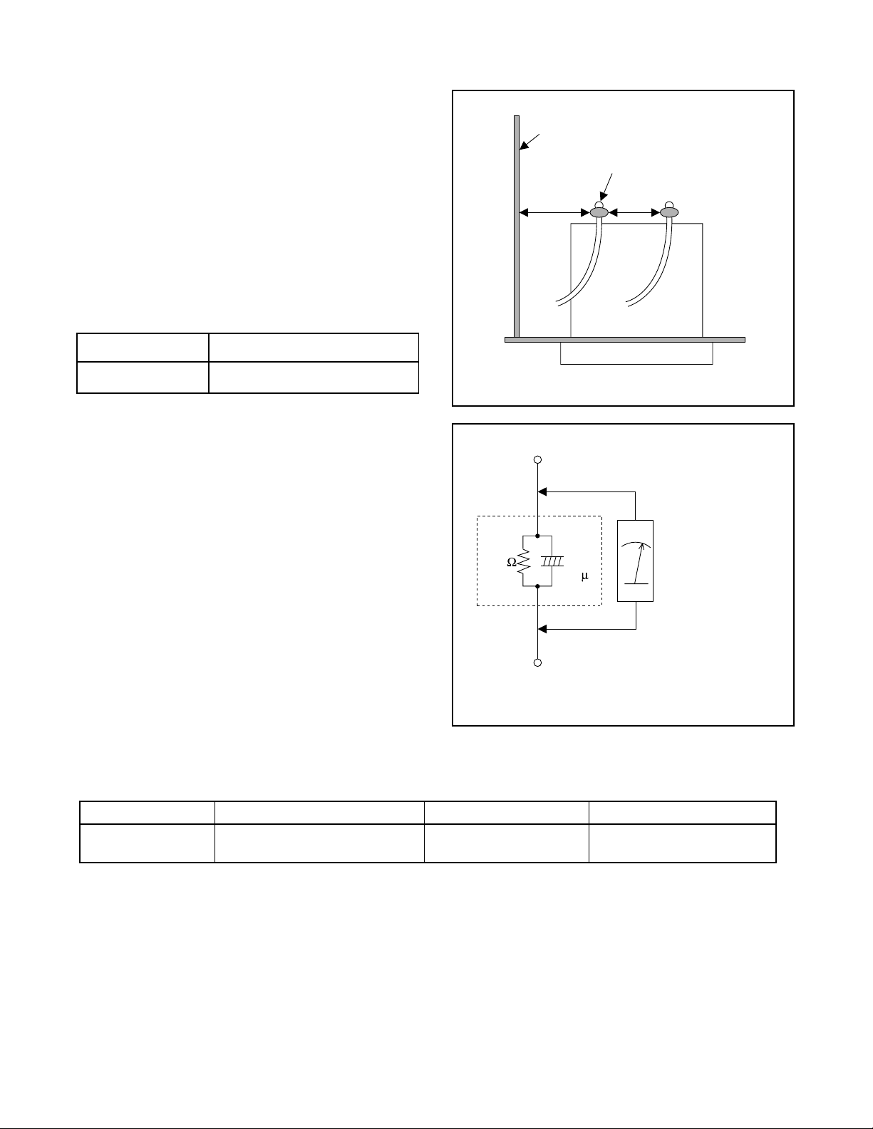
1. Clearance Distance
When replacing primary circuit components, confirm
specified clearance distance (d) and (d’) between soldered terminals, and between terminals and surrounding metallic parts. (See Fig. 1)
Table 1 : Ratings for selected area
AC Line Voltage Clearance Distance (d) (d’)
Chassis or Secondary Conductor
Primary Circuit Terminals
dd'
120 V
Note: This table is unofficial and for reference only.
Be sure to confirm the precise values.
2. Leakage Current Test
Confirm the specified (or lower) leakage current
between B (earth ground, power cord plug prongs)
and externally exposed accessible parts (RF terminals, antenna terminals, video and audio input and
output terminals, microphone jacks, earphone jacks,
etc.) is lower than or equal to the specified value in the
table below.
Measuring Method (Power ON) :
Insert load Z between B (earth ground, power cord
plug prongs) and exposed accessible parts. Use an
AC voltmeter to measure across the terminals of load
Z. See Fig. 2 and the following table.
Table 2: Leakage current ratings for selected areas
AC Line Voltage Load Z Leakage Current (i) Earth Ground (B) to:
120 V
≥ 3.2mm (0.126 inches)
0.15µF CAP. & 1.5kΩ RES.
Connected in parallel
Exposed Accessible Part
Z
1.5k
i≤0.5mA Peak Exposed accessible parts
0.15 F
Earth Ground
B
Power Cord Plug Prongs
AC Voltmeter
(High Impedance)
Fig. 1
Fig. 2
Note: This table is unofficial and for reference only. Be sure to confirm the precise values.
1-2
1-2 STANDARD NOTES FOR SERVICING
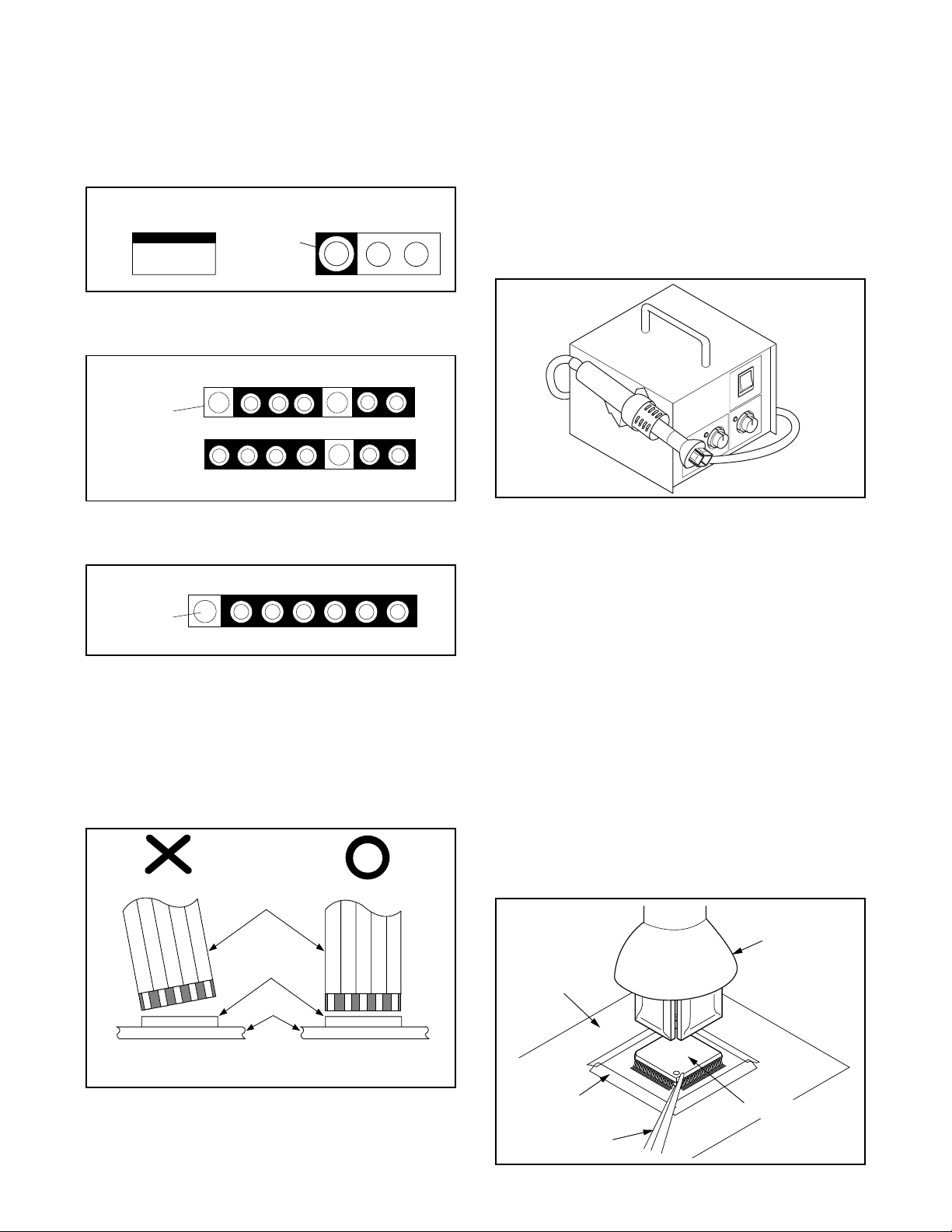
1-2-1 Circuit Board Indications
a. The output pin of the 3 pin Regulator ICs is indi-
cated as shown.
Top View
Input
Out
b. For other ICs, pin 1 and every fifth pin are indicated
as shown.
In
Pin 1
c. The 1st pin of every male connector is indicated as
shown.
Pin 1
Bottom View
5
10
1-2-3 How to Remove / Install Flat
Pack-IC
1. Removal
With Hot-Air Flat Pack-IC Desoldering Machine:.
(1) Prepare the hot-air flat pack-IC desoldering
machine, then apply hot air to the Flat Pack-IC
(about 5 to 6 seconds). (Fig. S-1-1)
Fig. S-1-1
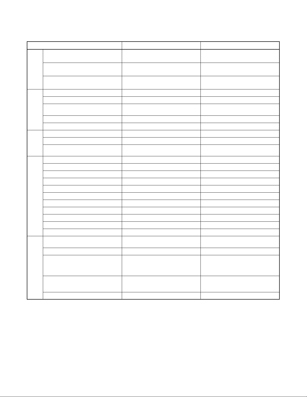
(2) Remove the flat pack-IC with tweezers while apply-
ing the hot air.
(3) Bottom of the flat pack-IC is fixed with glue to the
CBA; when removing entire flat pack-IC, first apply
soldering iron to center of the flat pack-IC and heat
up. Then remove (glue will be melted). (Fig. S-1-6)
(1) Release the flat pack-IC from the CBA using twee-
zers. (Fig. S-1-6)
1-2-2 Instructions for Connectors
1. When you connect or disconnect the FFC (Flexible
Foil Connector) cable, be sure to first disconnect
the AC cord.
2. FFC (Flexible Foil Connector) cable should be
inserted parallel into the connector, not at an angle.
FFC Cable
Connector
CBA
* Be careful to avoid a short circuit.
Caution:
1. Do not supply hot air to the chip parts around the
flat pack-IC for over 6 seconds because damage to
the chip parts may occur. Put masking tape around
the flat pack-IC to protect other parts from damage.
(Fig. S-1-2)
2. The flat pack-IC on the CBA is affixed with glue, so
be careful not to break or damage the foil of each
pin or the solder lands under the IC when removing
it.
Hot-air
Flat Pack-IC
Desoldering
CBA
Masking
Tape
Tweezers
Machine
Flat Pack-IC
Fig. S-1-2
1-3
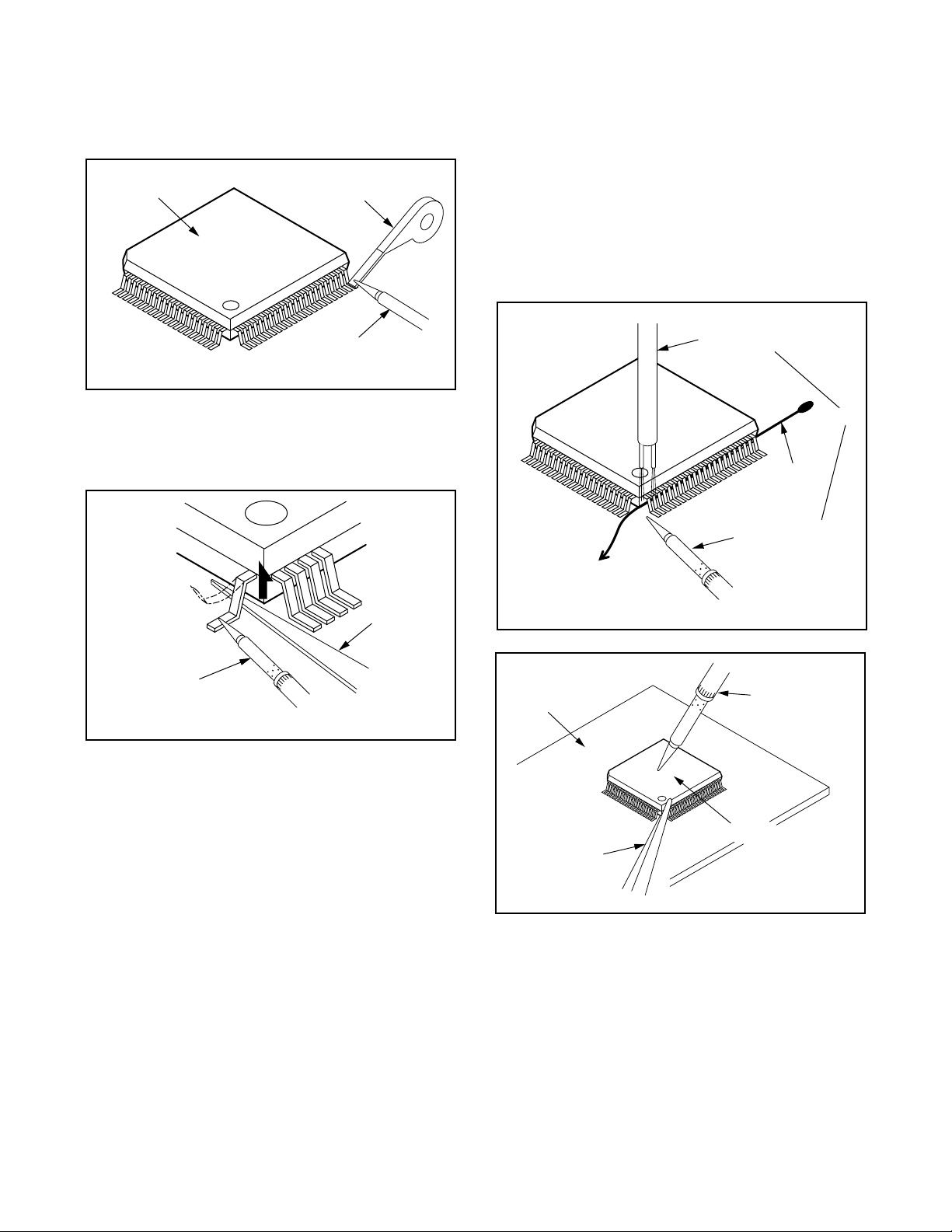
With Soldering Iron:
(1) Using desoldering braid, remove the solder from all
pins of the flat pack-IC. When you use solder flux
which is applied to all pins of the flat pack-IC, you
can remove it easily. (Fig. S-1-3)
Flat Pack-IC
Desoldering Braid
(4) Bottom of the flat pack-IC is fixed with glue to the
CBA; when removing entire flat pack-IC, first apply
soldering iron to center of the flat pack-IC and heat
up. Then remove (glue will be melted). (Fig. S-1-6)
(5) Release the flat pack-IC from the CBA using twee-
zers. (Fig. S-1-6)
Note:
When using a soldering iron, care must be taken
to ensure that the flat pack-IC is not being held by
glue. When the flat pack-IC is removed from the
CBA, handle it gently because it may be damaged
if force is applied.
Soldering Iron
Fig. S-1-3
(2) Lift each lead of the flat pack-IC upward one by
one, using a sharp pin or wire to which solder will
not adhere (iron wire). When heating the pins, use
a fine tip soldering iron or a hot air desoldering
machine. (Fig. S-1-4)
Sharp
Pin
Fine Tip
Soldering Iron
Fig. S-1-4
(3) Bottom of the flat pack-IC is fixed with glue to the
CBA; when removing entire flat pack-IC, first apply
soldering iron to center of the flat pack-IC and heat
up. Then remove (glue will be melted). (Fig. S-1-6)
(4) Release the flat pack-IC from the CBA using twee-
zers. (Fig. S-1-6)
With Iron Wire:
(1) Using desoldering braid, remove the solder from all
pins of the flat pack-IC. When you use solder flux
which is applied to all pins of the flat pack-IC, you
can remove it easily. (Fig. S-1-3)
(2) Affix the wire to a workbench or solid mounting
point, as shown in Fig. S-1-5.
(3) While heating the pins using a fine tip soldering
iron or hot air blower, pull up the wire as the solder
melts so as to lift the IC leads from the CBA contact
pads as shown in Fig. S-1-5
To Solid
Mounting Point
CBA
Tweezers
Hot Air Blower
or
Iron Wire
Soldering Iron
Fig. S-1-5
Fine Tip
Soldering Iron
Flat Pack-IC
Fig. S-1-6
1-4
2. Installation
(1) Using desoldering braid, remove the solder from
the foil of each pin of the flat pack-IC on the CBA
so you can install a replacement flat pack-IC more
easily.
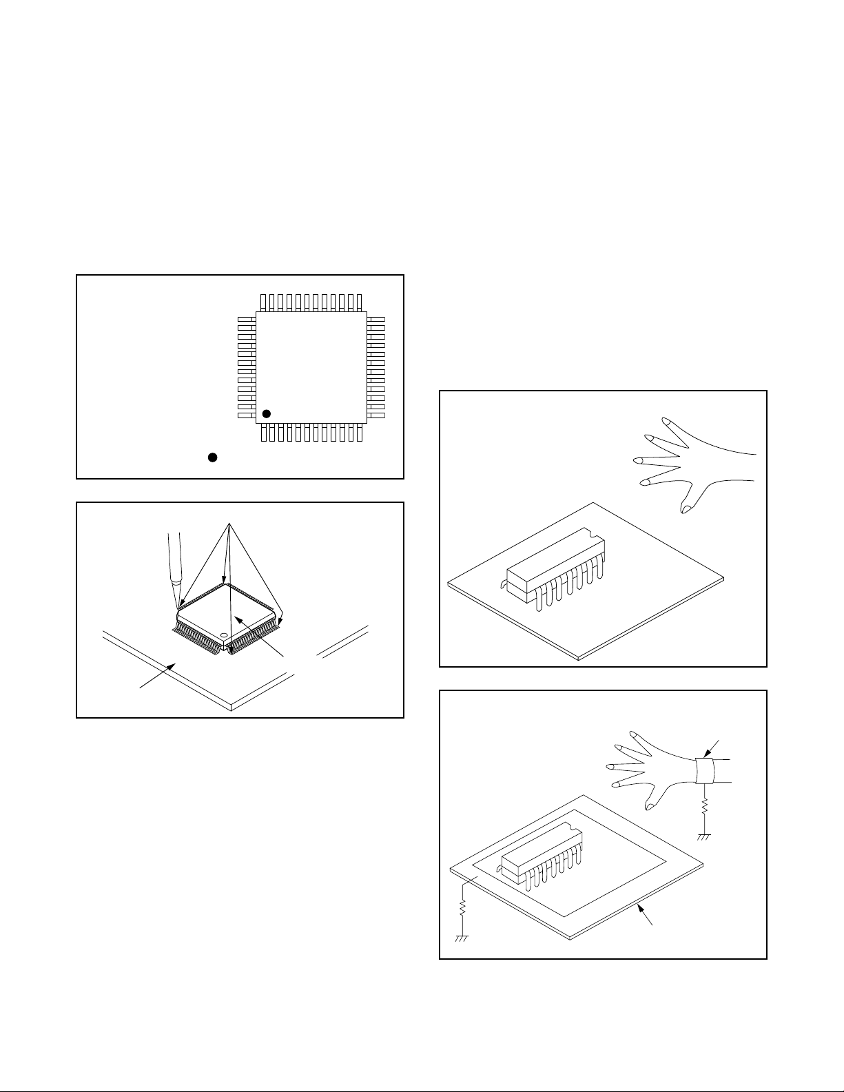
(2) The “I” mark on the flat pack-IC indicates pin 1.
(See Fig. S-1-7.) Be sure this mark matches the 1
on the PCB when positioning for installation. Then
presolder the four corners of the flat pack-IC. (See
Fig. S-1-8.)
(3) Solder all pins of the flat pack-IC. Be sure that none
of the pins have solder bridges.
Example :
Pin 1 of the Flat Pack-IC
is indicated by a " " mark.
Fig. S-1-7
1-2-4 Instructions for Handling
Semi-conductors
Electrostatic breakdown of the semi-conductors may
occur due to a potential difference caused by electrostatic charge during unpacking or repair work.
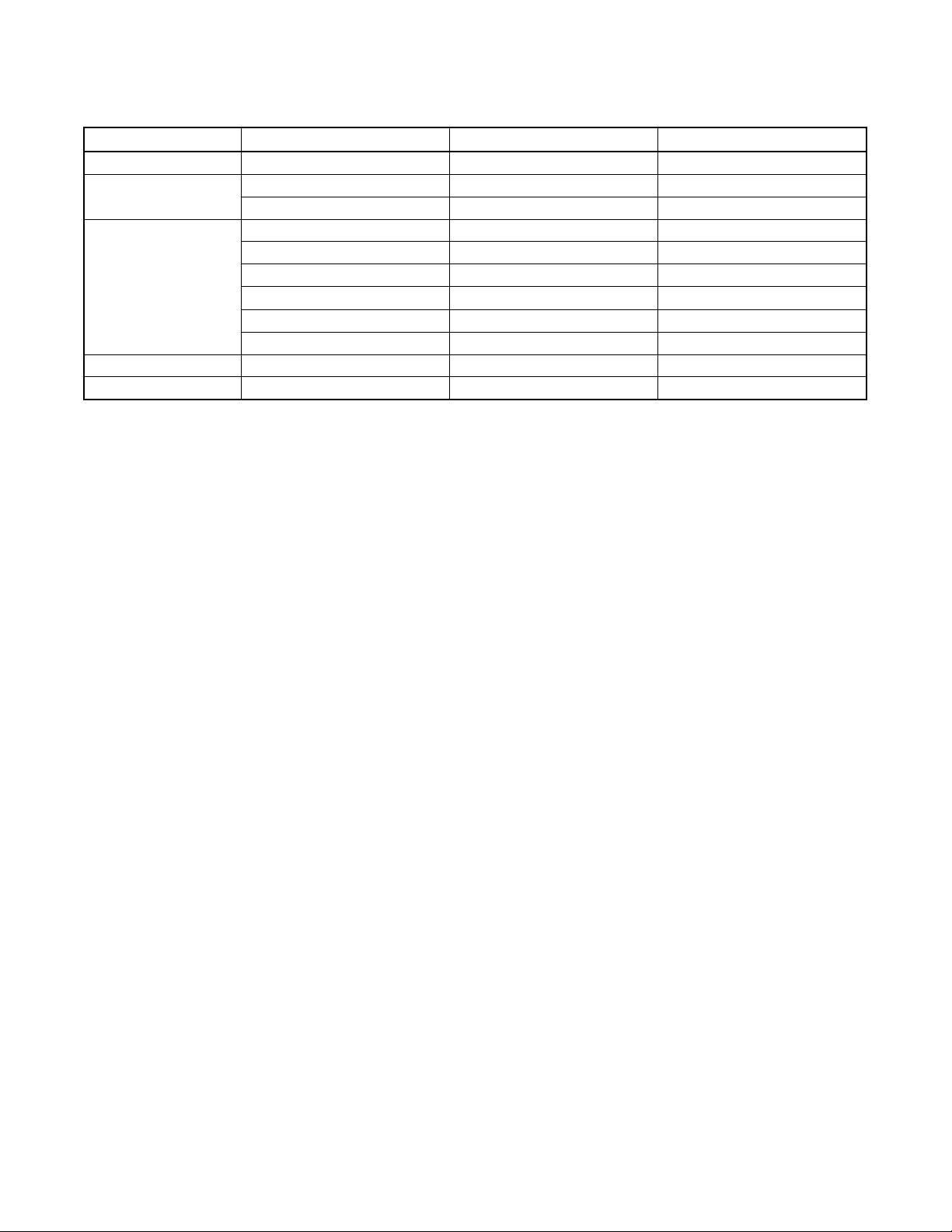
1. Ground for Human Body
Be sure to wear a grounding band (1MΩ) that is properly grounded to remove any static electricity that may
be charged on the body.
2. Ground for Workbench
(4) Be sure to place a conductive sheet or copper plate
with proper grounding (1MΩ) on the workbench or
other surface, where the semi-conductors are to be
placed. Because the static electricity charge on
clothing will not escape through the body grounding band, be careful to avoid contacting semi-conductors with your clothing.
< Incorrect >
CBA
Presolder
Flat Pack-IC
Fig. S-1-8
CBA
< Correct >
Grounding Band
1MΩ
CBA
1MΩ
Conductive Sheet or
Copper Plate
1-5

2
GENERAL DESCRIPTION
2-1 SPECIFICATIONS
Format: VHS
Video Signal System: NTSC color EIA standard
Record/Playback System:Video: 4 heads
Audio: VHS Hi-Fi stereo record/playback system
Tape Speed: 33.35mm/s(SP), 16.67mm/s (LP) (Playback Only), 11.12mm/s (SLP)
RF Input: UHF/VHF 75 ohm
Tuner: 181 channel tuning ability *(125 cable channel)
Type: Auto programming frequency synthesis
Power Input: AC120V 60Hz
Power Consumption: 14W nominal
Cabinet Size: 14-1/4” (W) x 3-5/8” (H) x 8-1/2” (D) / 360 mm (W) x 92 mm (H) x 216 mm (D)
Weight: 4.0 lbs. (1.8 kg) (approx.)
Storage Temperature: -4 F to 131 F
Operating Temperature: 41 F to 104 F (5 C to 40 C)
*Check your cable company’s compatibility requirements.
• Designs and specifications are subject to change without notice.
2-1
2-2 COMPARISON OF MODELS
2-2-1 Comparison of Features
ITEM VT-FX795A VT-FX695A/FX695AC
Cabinet Size 360(W) x 92(H) x 216(D) mm 435(W) x 92(H) x 216(D) mm
Weight 1.8 kg 2.5 kg
Power Consumption 14 W 14 W
APPEARANCE
Video Format VHS VHS
Y/C Separation Comb Filter Comb Filter
YNR (Luminance Noise Reduction)
Circuit
VIDEO
New Synchronise Circuit [[
Picture Control [[
Video/Audio Input (Rear) 1/1 (IN1) 1/1 (IN1)
Video/Audio Input (Front) 1/1 (IN2) 1/1 (IN2)
INPUT/
Video/Audio Output (Rear) 1/1 (OUT1) 1/1 (OUT1)
OUTPUT
Remote Controller VT-RM795A VT-RM695A
Stereo CM Skip Feature [[
Auto Clock Feature O (Manual Channel Setting) O (Manual Channel Setting)
Number of Timer Programming 7 Program/year 7 Program/year
Self Diagnosis Funtion O (4 Modes) O (4 Modes)
Back-up Time 30 s 30 s
OTHERMECHANISM
SQPB O O
Surge Absorber O O
Auto Power Off Feature O O
Local Broadcast Setting O O
Multi Search Feature O (Index, Time Search) O (Index, Time Search)
Search Speed
FF/REW Time (T-120 Tape)
Head Composition
Head Material
VISS O (Index Search) O (Index Search)
FF: approx. 4 min, REW: approx. 4 min FF: approx. 4 min, REW: approx. 4 min
Hi-Fi Audio: 2[28/28 µm]
SP: X5
EP: X5/X15
DA4+Hi-Fi
SP: 2[49/58 µm]
EP: 2[21/21 µm]
SP: Ferrite
EP: Ferrite
Hi-Fi Audio: Ferrite
OO
SP: X5
EP: X5/X15
DA4+Hi-Fi
SP: 2[49/58 µm]
EP: 2[21/21 µm]
Hi-Fi Audio: 2[28/28 µm]
SP: Ferrite
EP: Ferrite
Hi-Fi Audio: Ferrite
2-2
2-2-2 Comparison of Main Control ICs
ITEM OPERATION VT-FX795A VT-FX695A/FX695AC
Video Video Signal Process LA71091M(IC301) LA71091M(IC301)
Audio
System Control
Timer Display Driver Included in IC501 Included in IC501
Power Switching Driver - -
FM Audio Signal Process LA72670M(IC451) LA72655M(IC451)
Linear Audio Signal Process Included in IC301 Included in IC301
Main Microcomputer µP MN101D08EFA4(IC501) M37765MAA1N1GP(IC501)
VCR-EEP ROM - -
Reset - -
Loading Motor Drive - -
Cylinder/Loading Motor Control - -
Power Reset - -
2-3
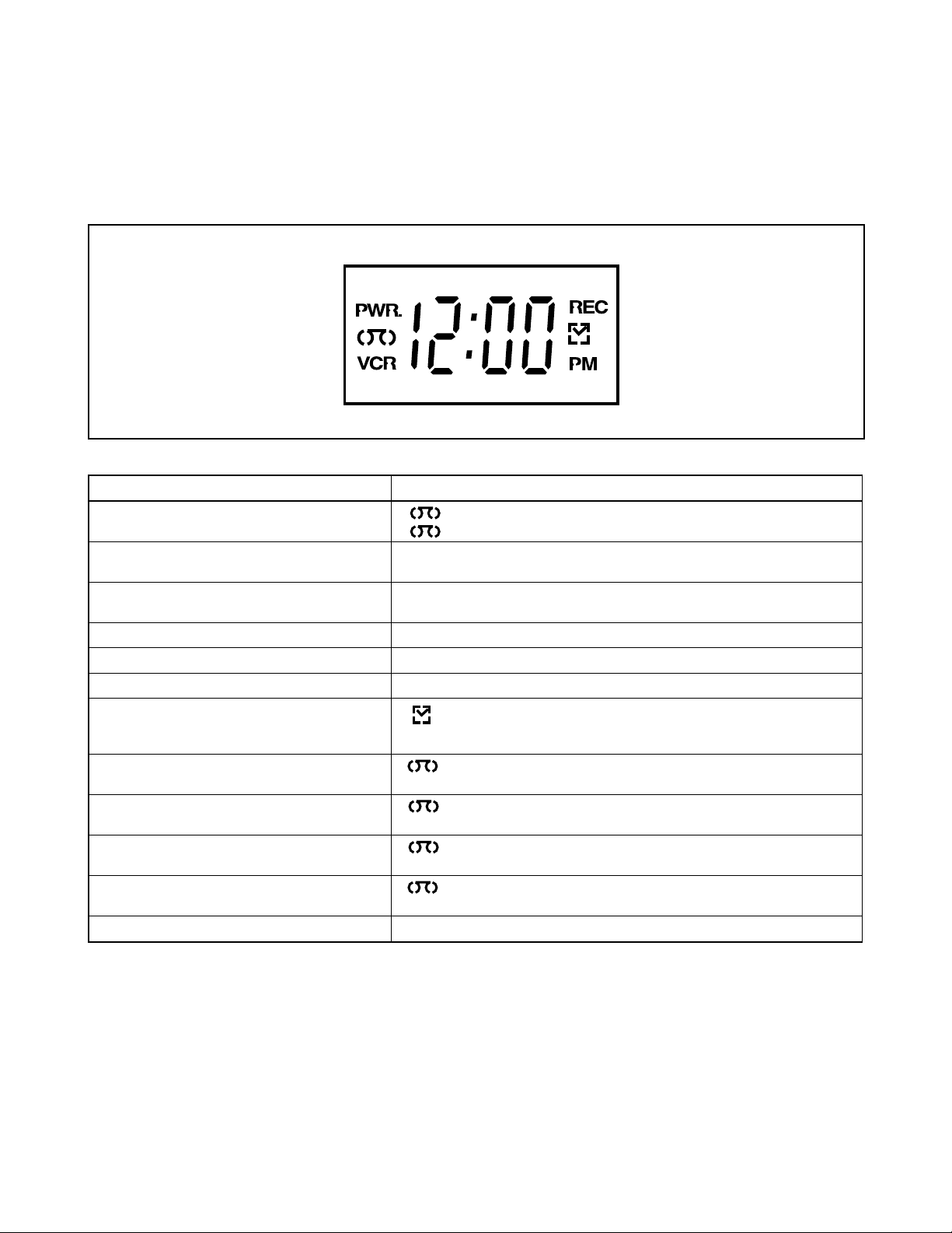
2-3 FUNCTION INDICATOR SYMBOLS
Note:
The following symbols will appear on the indicator panel to indicate the current mode or operation of the VCR.
On-screen modes will also be momentarily displayed on the tv screen when you press the operation buttons.
Display panel
LED MODE INDICATOR ACTIVE
CASSETTE "IN"
CASSETTE "OUT"
VCR/TV VCR MODE
VCR/TV TV MODE
CLOCK " 88:88 "
POWER ON " PWR. " ON
REC " REC " ON
REC PAUSE " REC " Blinks at 0.8Hz interval
T-REC, OTR " " ON
When reel and capstan mechanism is not
functioning correctly
When tape loading mechanism is not functioning correctly
When cassette loading mechanism is not
functioning correctly
When the drum is not working properly " "
S-INH condition All modes Blinks at 0.8Hz interval
" "
" "
" VCR "
" VCR "
" PM "
" "
" 1 "
" "
" 2 "
" "
" 3 "
" 4 "
ON
OFF
ON
OFF
ON
ON/OFF
(T-REC OFF, T-REC incomplete
Blinks at 0.8Hz interval)
Blinks at 0.8Hz interval
Blinks at 0.8Hz interval
Blinks at 0.8Hz interval
Blinks at 0.8Hz interval
2-4
s
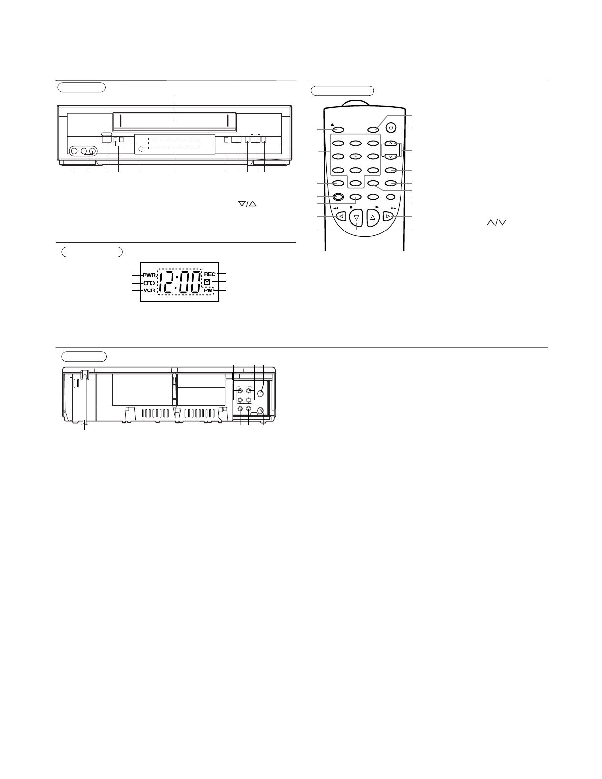
2-4 OPERATING CONTROLS AND FUNCTIONS
Front Panel
POWER CHANNEL
L-AUDIO IN-RVIDEO IN
12
nm
1. Cassette Compartment
2. F.FWD button
3. PLAY button
4. REW button
5. STOP/EJECT button
6. REC/IRT button
Display Window
13
14
15
13. PWR. indicator
14. TAPE IN indicator
15. VCR indicator
Rear Panel
25
19. AUDIO OUT jacks
20. AUDIO IN jacks
21. ANT. IN jack
22. ANT. OUT jack
1
REC/IRT STOP/EJECT REW PLAY F.FWD
ab
PNV
234567891011
17. Display Window
18. Remote Sensor
19. CHANNEL buttons
(
)
10. POWER button
11. AUDIO Input jacks
12. VIDEO Input jack
16
17
18
16. REC indicator
17. TIMER indicator
18. CLOCK indicator
19 20 21
ANT
AUDIO
IN
L
IN
OUT
R
VIDEO
OUT
OUT IN
242322
23. VIDEO IN jack
24. VIDEO OUT jack
25. AC Power Cord
Remote Control
17
POWER
1
2
3
4
5
6
7
VCR/TVEJECT
123
456
7809
MENU
RECORD
REW
SLOW
DISPLAYSPEED
PLAY
P
O
T
S
CHANNEL
SEARCH
C.RESET
F
.F
-MODE
PAUSE
/STILL
W
16
15
14
EXIT
13
12
11
10
D
9
8
VIDEO OUT Jack
Connect a video cable going to
the video in jack of a camcorder,
another VCR, a TV, or an audiovisual system (laser disc player,
video disc player, etc.) here.
AUDIO OUT Jacks
Connect the audio cables going
to the audio in jacks of a camcorder, another VCR, a stereo
amplifier, or an audio system
here.
1. EJECT button
2. NUMBER buttons
3. MENU button
4. RECORD button
5. SPEED button
6. REW button
7. STOP button
8. PLAY button
9. F.FWD button
10. DISPLAY button
11. PAUSE/STILL button
12. SLOW button
13. C.RESET/EXIT button
14. SEARCH-MODE button
15. CHANNEL buttons
(
)
16. POWER button
17. VCR/TV button
VIDEO IN Jack
Connect a video cable coming
from the video out jack of a
camcorder, another VCR, or an
audio-visual source (laser disc
player, video disc player, etc.)
here.
AUDIO IN Jacks
Connect the audio cables coming from the audio out jacks of a
camcorder, another VCR, or an
audio source here.
2-5
3
TROUBLESHOOTING
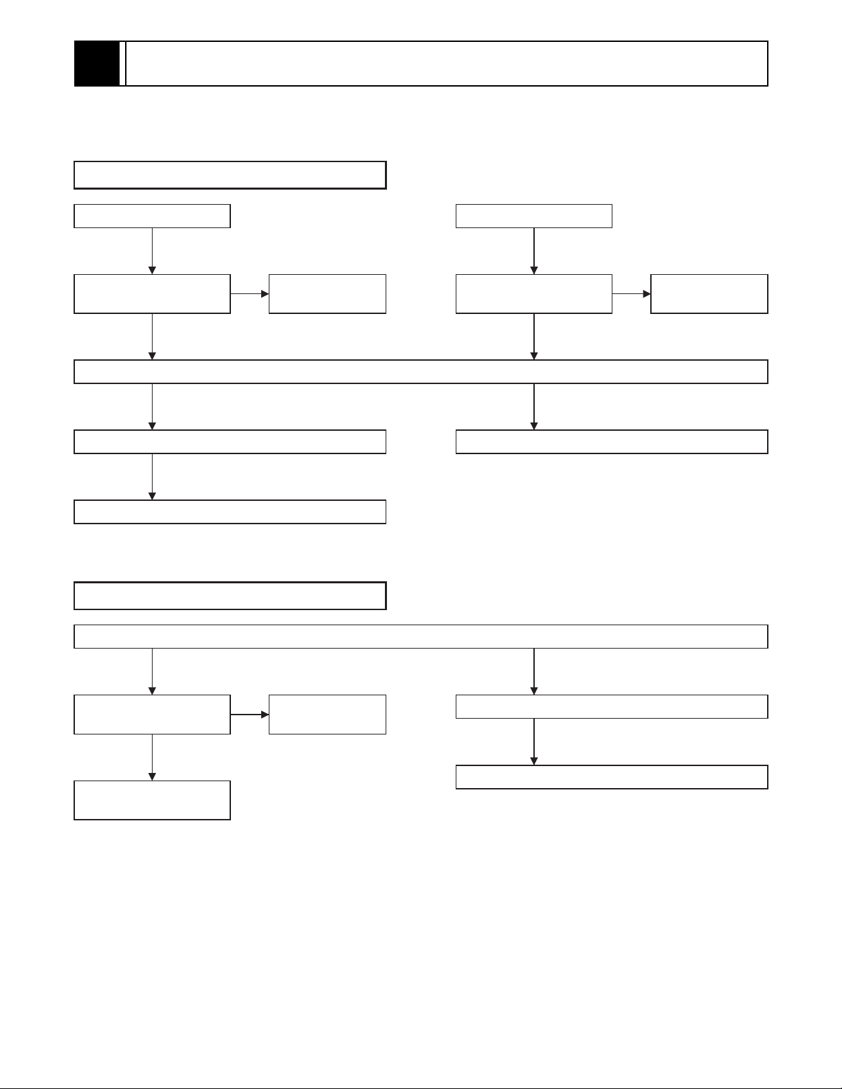
3-1 TROUBLESHOOTING
Video problem 1 (No recording Video)
RF INPUT
Check Video signal at pin
42 of IC301.
Check signal at pin 89(or pin90) or pin84(or pin83) of IC301.
OK
Cleaning Video the Head. (See page 3-6.) Check IC301, Q301, X301, etc.
NG
Check Cylinder Assembly.
Check TU701.
NG NG
LINE INPUT
Check Video signal at pin
38(or pin40) of IC301.
OKOK
NG
Video problem 2 (No playback Video)
Check A/V cable.
Check signal at pin 91(and pin88) and pin85(or pin82) of IC301.
OK
Check Video signal at pin
35 of IC301.
OK
Check Q391, TU701, or
V-OUT jack.
NG
Check IC301, Q301,
X301, etc.
NG
Cleaning Video Head. (See page 3-6.)
NG
Check Cylinder Assembly.
3-1
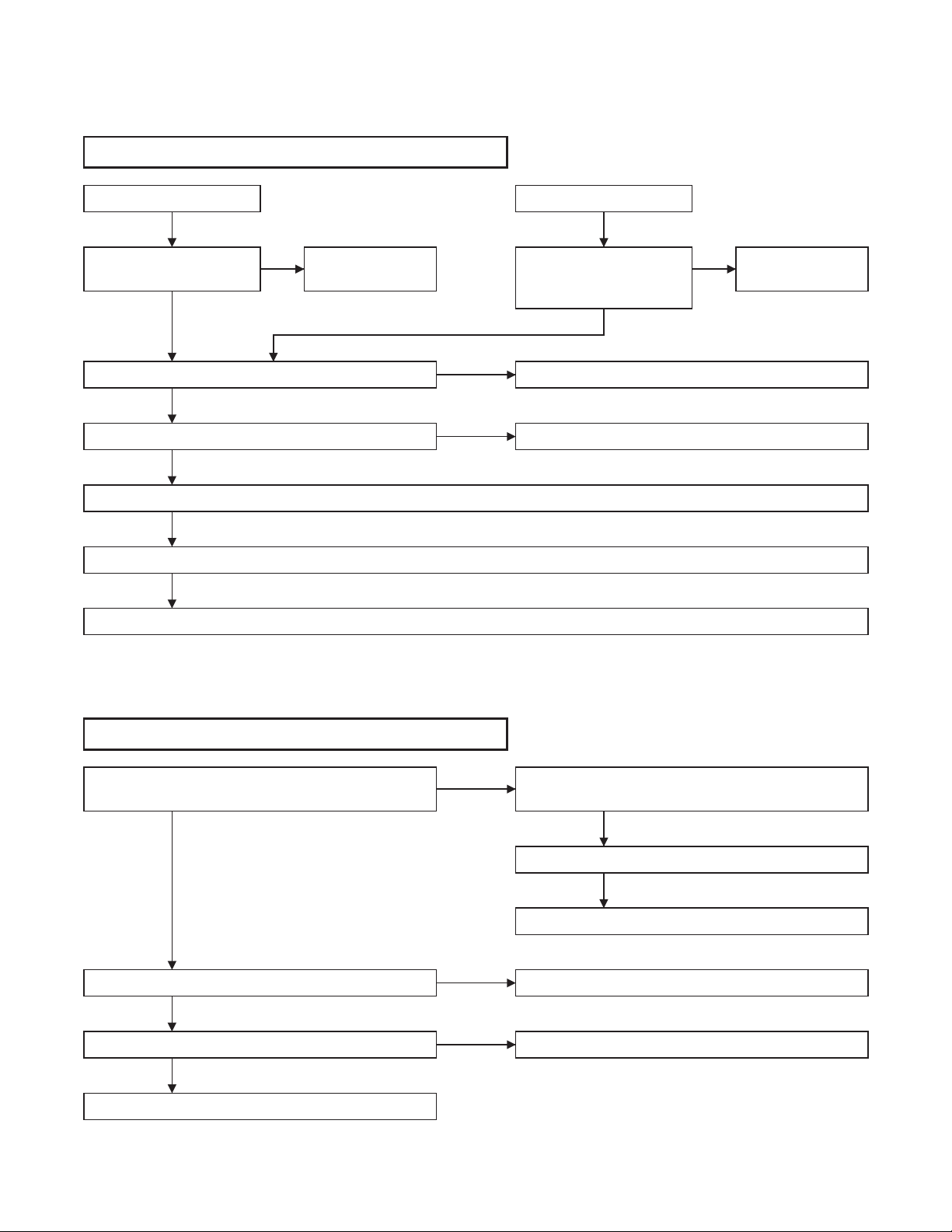
Audio problem 1 (No recording Normal Audio)
RF INPUT
Check SIF signal at pin
57 of IC451.
OK
Check Audio signal at pin 6 of IC451.
OK
Check Audio signal at pin 7 of IC301.
OK
Check Tape Interchangeability Alignment. (See page 4-5.)
NG
Cleaning the Audio Control Erase Head. (See page 3-6.)
NG
Check ACE Head Assembly.
NG NG
Check TU701.
NG
NG
LINE INPUT
Check Video signal at pin
69(or pin71) or pin 7
(or pin9)of IC451.
OK
Check IC451.
Check IC301.
Check A/V cable.
Audio problem 2 (No playback Normal Audio)
Check Audio signal at pin 4 of IC301.
OK
Check Audio signal at pin 96 of IC301.
OK
Check Audio signal at pin 80(or pin78 or pin2) of IC451.
OK
Check TU701 or A-OUT jack.
3-2
NG
NG
NG
Check Tape Interchangeability Alignment.
(See page 4-5.)
NG
Cleaning the Audio Control Erase Head. (See page 3-6.)
NG
Check ACE Head Assembly.
Check IC301.
Check IC451.
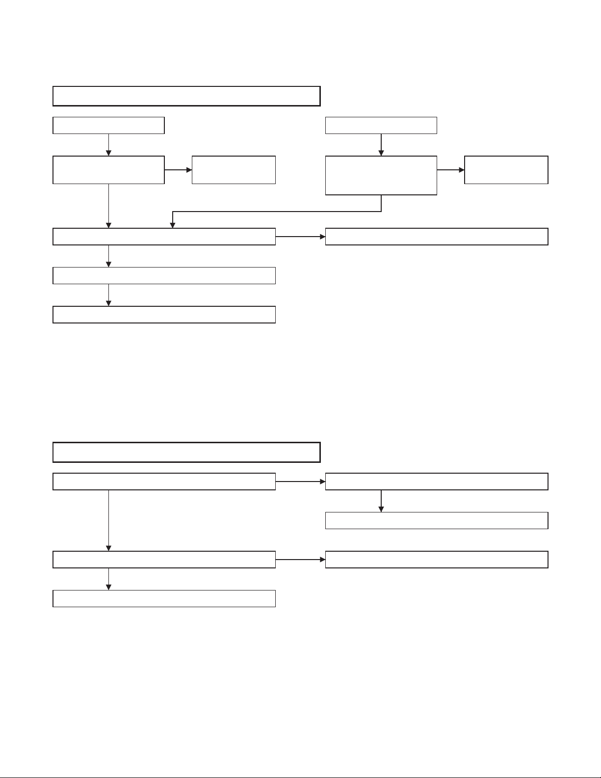
Audio problem 3 (No recording Hi-Fi Audio)
RF INPUT
Check SIF signal at pin
57 of IC451.
OK
Check signal at pin 26 of IC451.
OK
Cleaning the Video Head. (See page 3-6.)
NG
Check Cylinder Assembly.
NG NG
Check TU701.
NG
LINE INPUT
Check Video signal at pin
69(or pin71) or pin 7
(or pin9) of IC451.
OK
Check IC451.
Check A/V cable.
Audio problem 4 (No playback Hi-Fi Audio)
Check signal at pin 24(and pin27) of IC451.
OK
Check Audio signal at pin 80(or pin78 or pin2) of IC451.
OK
Check TU701 or A-OUT jack.
NG
NG
Cleaning the Video Head. (See page 3-6.)
NG
Check Cylinder Assembly.
Check IC451.
3-3
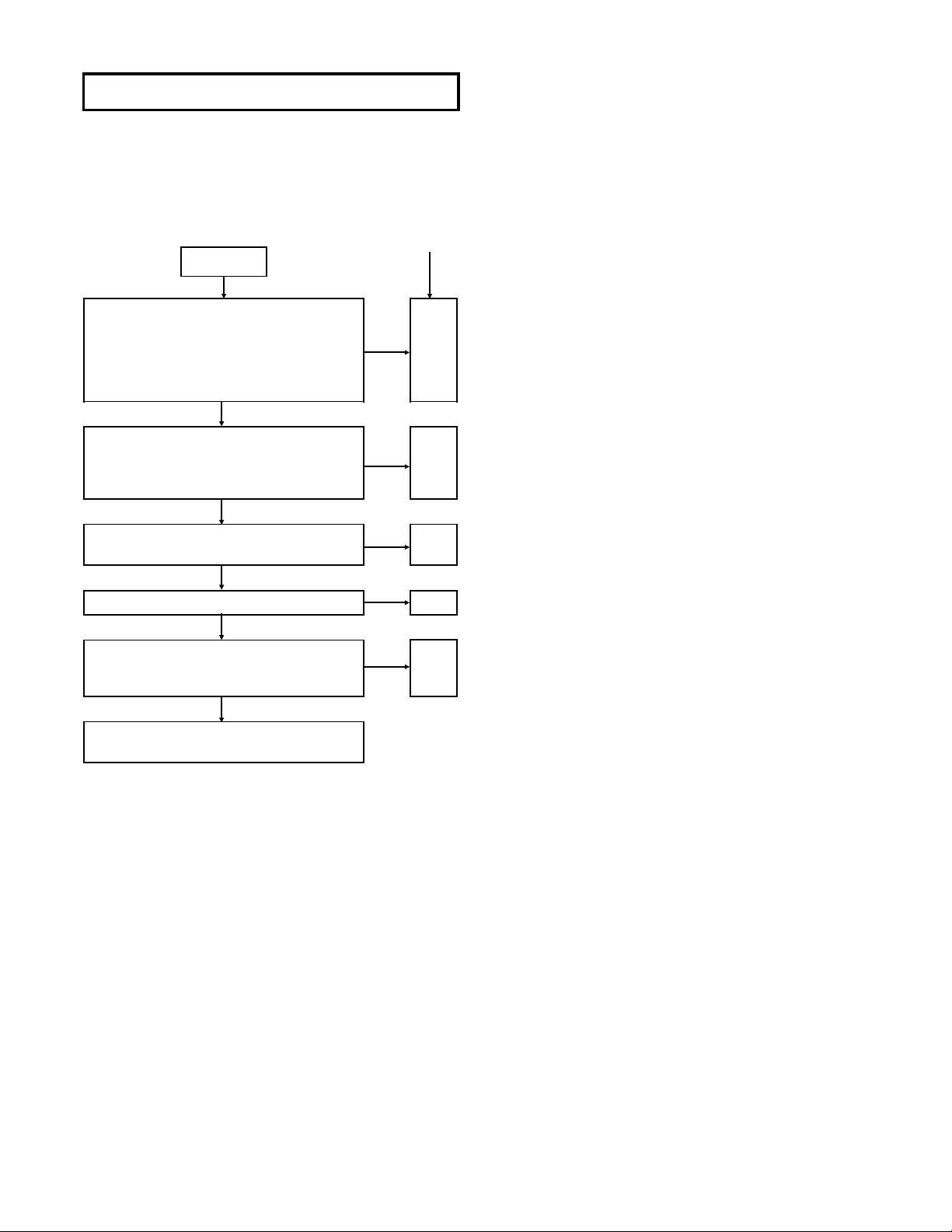
Power problem
It is highly recommended that a variable isolation
transformer which can monitor current be used.
(Alternatively a variable AC source which monitors current will do). Read directions below before
power is added!
1] Check for any defective parts while the secondary
rectifying diodes are disconnected. Perform a diode
check in both forward and reverse directions through a
tester.
2] Remove the following components and check for
defects: snubber diode (D051), switching FET (Q001),
source resistor (R014), control transistor (Q002).
Repair method
CHECK
Connect unit to the isolation transformer and slowly increase the AC supply while monitoring the current, if it
draws too much current (Be ware fuse
is rated for 1.0 amps), then turn off
supply and do repair method #1.
NO
Check whether the primary rectifying
DC of the Switching power supply has
an output. (Reading should be about
168V.)
YES
With the primary DC working check
the secondary 5V.
YES
Are the 40V, 12V, and 5V than normal?
NO
Although the secondary 5V is working,
are any of the other voltages higher
than normal (40V, 12V)?
NO
There is no problem on the SW power
supply.
YES
NO
NO
YES
YES
#1
#2
#3
#4
#5
Repair method #1
(Power must be off)
Short circuit in the secondary side. Check diode D013,
D015, D016, switching FET (Q001), control transistor
(Q002, Q029), diode (D006), and resistor (R014)
replace as necessary.
Disconnect 40V diode (D013), 12V diode (D015), and
5V diode (D016). Check the load continuity of 40V
line, 12V line, and 5V line through a tester (resistance
range).
If the tester indicates a lower resistance value around
0 ohm, the line is short-circuited.
Before repairing the switching power supply, find out
the short-circuited area of such line and repair it.
If the tester does not indicate any low resistance value
(around 0 ohm), no load is short-circuited and there is
no problem.
Repair method #2
Check the fuse 1.0A (F001), primary rectifying diodes
(D001-D004) as possible problems. Remove the
above mentioned parts and check them. The circuit
which turns on switching FET (Q001) may be
regarded as a possible cause, even if the load at the
secondary side is shorted, it can't be detected
because switching FET (Q001) isn't operating. Perform check according to the step 1] and 2] of repair
method #1 and check the following parts:
(Remove the part from PCB)
Switching FET (Q001), source resistor (R014), gate
resistor (R008) and start resistor (R004 and R005).
Repair method #3
A circuit to turn on switching FET (Q001) may not work
and this may be regarded as a cause of trouble. Even
if the load at the secondary side is short-circuited, it
cannot be detected because switching FET (Q001)
does not turn on. Therefore, perform check according
to the steps 1] and 2] of the repair method #1 and execute the under-mentioned parts breakage check.
(Remove the part from PCB.)
switching FET (Q001), source resistor (R014), control
transistor (Q002), gate resistor (R008) and start resistor (R004 and R005).
Repair method #4
The feedback circuit which is monitored by the output
of voltage may not work and this may be regarded as
a possible cause, remove control transistor Q002 and
check for defects. More over, a photo coupler (IC001)
and transistor (Q031) may be defective, replace any
defective parts with factory originals.
Repair method #5
If the output voltage of the secondary side is slightly
high, the line load may be in the "OPEN" state and this
may be regarded as a cause of trouble. If there is no
output voltage on the secondary side, the rectifying
diodes (D013, D015).
3-4
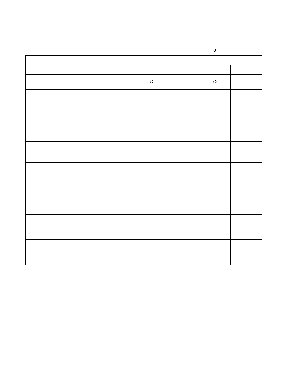
3-2 STANDARD MAINTENANCE
3-2-1 Service Schedule of Components
h: Hours : Check I: Change
Deck Periodic Service Schedule
Ref.No. Part Name 1,000 h 2,000 h 3,000 h 4,000 h
B2
B3 Loading Motor Assembly
B8
B587
B31 ACE Head Assembly
B573,B574
B37
B52 Cap Belt
*B73
B133,B134
B410 Pinch Arm Assembly II
B414
B416
Cylinder Assembly
Pulley Assembly
Tension Lever Assembly
Reel (SP)(D2), Reel (TU)(D2)
Capstan Motor
FE Head
Idler Gear, Idler Arm
M Brake (SP) Assembly
M Brake (TU) Assembly
II
I
II
II
I
I
II
II
I
II
II
II
B525 LDG Belt II
B569
(2 head only)
B593
(4 head,
4 head HiFi
only)
Notes:
1.Clean all parts for the tape transport (Upper Drum with Video Head / Pinch Roller / Audio Control Erase Head /
Full Erase Head) using 90% lsopropyl Alcohol.
2.After cleaning the parts, do all DECK ADJUSTMENTS.
3.For the reference numbers listed above, refer to Deck Exploded Views.
* B73 ------ Recording Model only
Cam Holder (F) II
Cam Holder (F) Assembly II
3-5
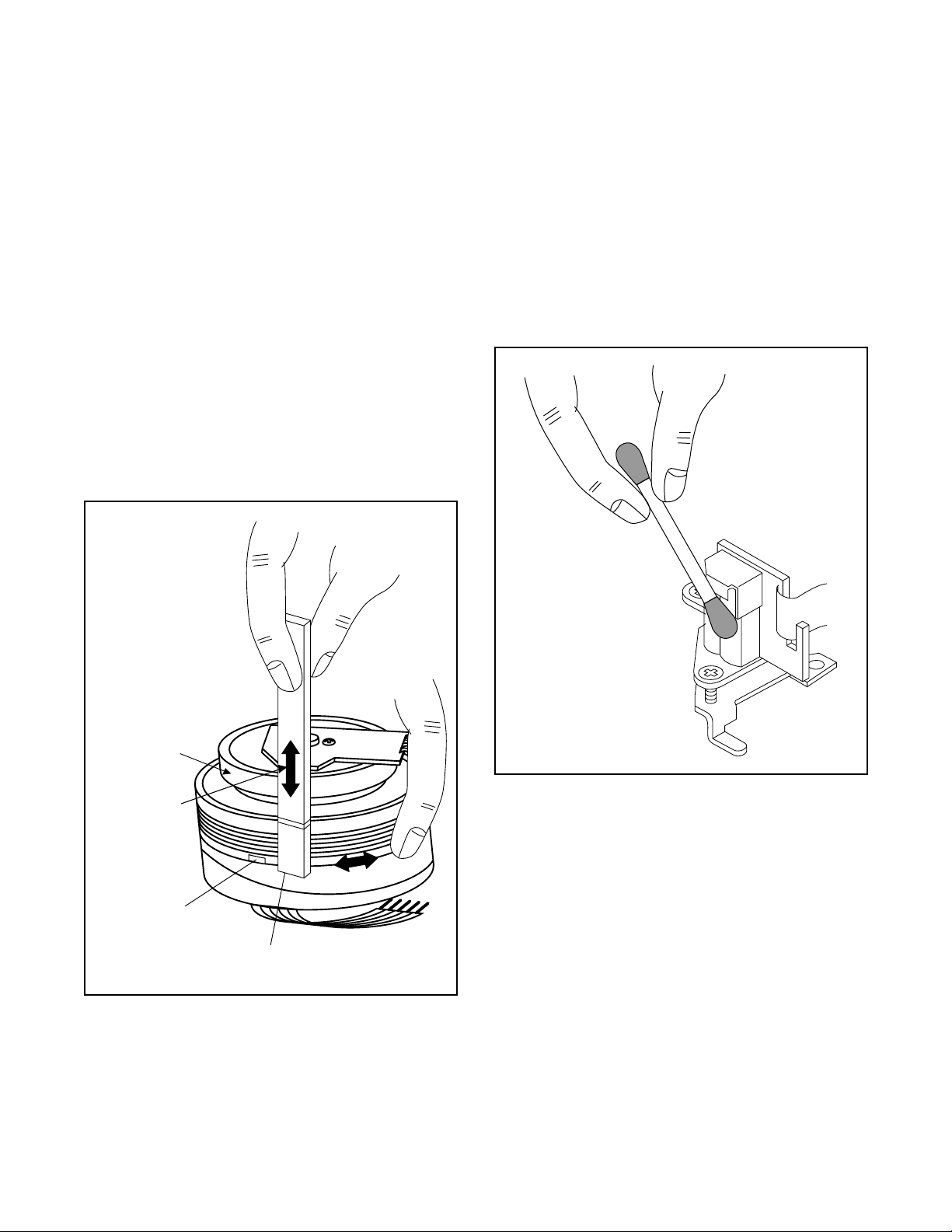
3-2-2 Cleaning
Cleaning of Video Head
Clean the head with a head cleaning stick or chamois
cloth.
Procedure
1.Remove the top cabinet.
2.Put on a glove (thin type) to avoid touching the
upper and lower drum with your bare hand.
3.Put a few drops of 90% Isopropyl alcohol on the
head cleaning stick or on the chamois cloth and,
by slightly pressing it against the head tip, turn the
upper drum to the right and to the left.
Notes:
1.The video head surface is made of very hard
material, but since it is very thin, avoid cleaning it
vertically.
2.Wait for the cleaned part to dry thoroughly before
operating the unit.
3.Do not reuse a stained head cleaning stick or a
stained chamois cloth.
Cleaning of Audio Control Erase Head
Clean the head with a cotton swab.
Procedure
1.Remove the top cabinet.
2.Dip the cotton swab in 90% Isopropyl alcohol and
clean the audio control erase head. Be careful not
to damage the upper drum and other tape running
parts.
Notes:
1.Avoid cleaning the audio control erase head vertically.
2.Wait for the cleaned part to dry thoroughly before
operating the unit or damage may occur.
Upper
Cylinder
Do Not !
Video Head
ACE Head
Cleaning Stick
3-6
4
ADJUSTMENT
4-1 PREPARATION FOR SERVICING
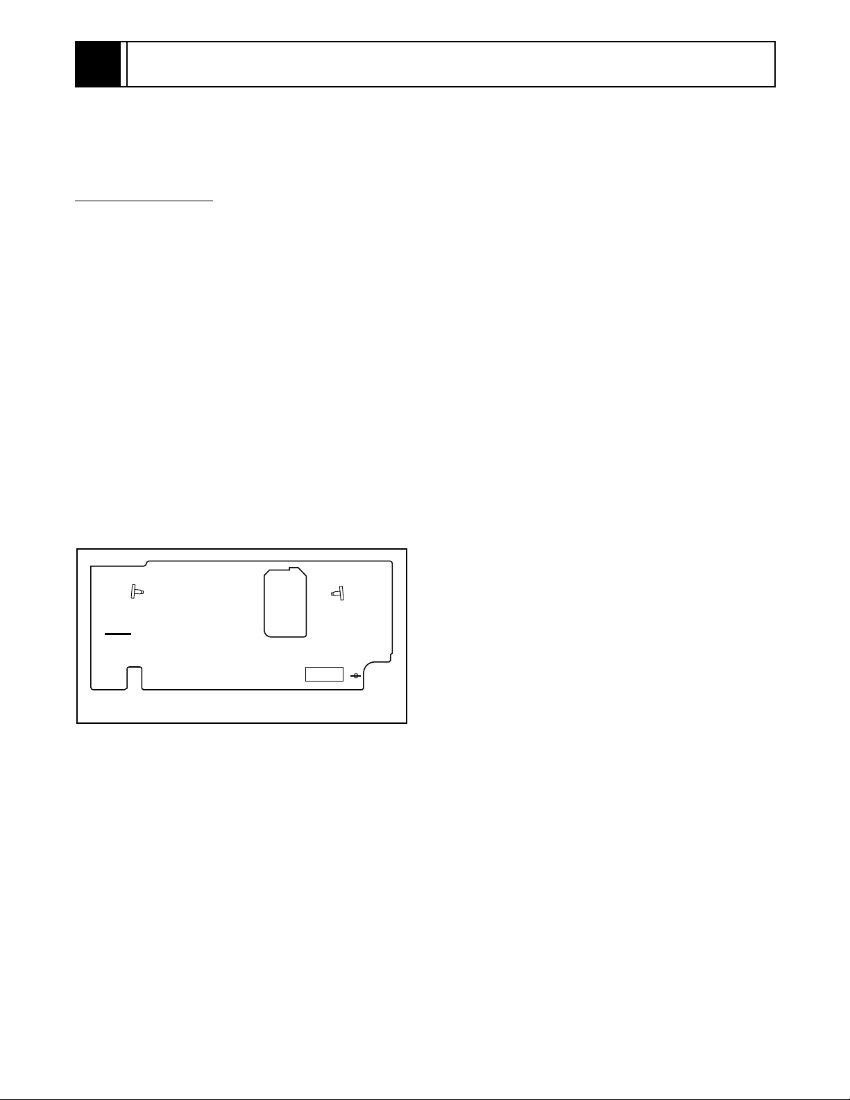
4-1-1 How to Enter the Service Mode
About Optical Sensors
Caution:
An optical sensor system is used for the Tape Start
and End Sensors on this equipment. Carefully read
and follow the instructions below. Otherwise the unit
may operate erratically.
What to do for preparation
Insert a tape into the Deck Mechanism Assembly and
press the PLAY button. The tape will be loaded into
the Deck Mechanism Assembly. Make sure the power
is on, TP502 (SENSOR INHIBITION) to J20 (GND).
This will stop the function of Tape Start Sensor, Tape
End Sensor and Reel Sensors. (If these TPs are connected before plugging in the unit, the function of the
sensors will stay valid.) See Fig. 1.
Note: Because the Tape End Sensors are inactive, do
not run a tape all the way to the start or the end of the
tape to avoid tape damage.
Q503
J20(GND)
Q504
TP502
S-INH
Fig. 1
4-1
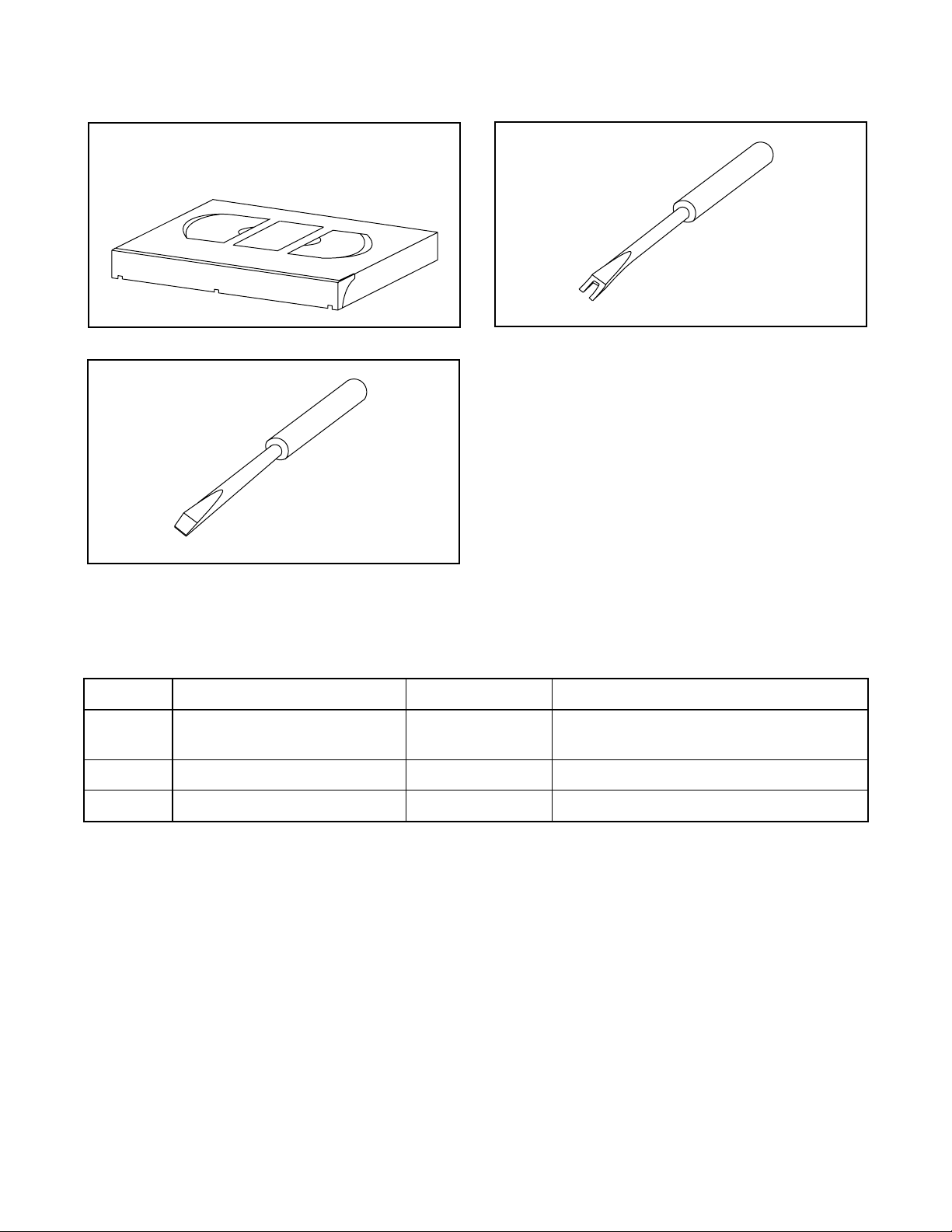
4-2 FIXTURE AND TAPE FOR ADJUSTMENT
1. Alignment Tape
No. 7099046 (MH-1)
3. Flat Screwdriver
(Purchase Locally)
2. Guide Roller Adj. Screwdriver
No. 7099028
4-2-1 How To Use The Fixtures And Tape
Item No. Name Part No. Adjustment
1 Alignment Tape 7099046
2 Guide Roller Adj. Screwdriver 7099028 I Guide Roller
3 Flat Screwdriver Purchase Locally I X Value Alignment
I Head Switching Point
I Tape Interchangeability Alignment
4-2
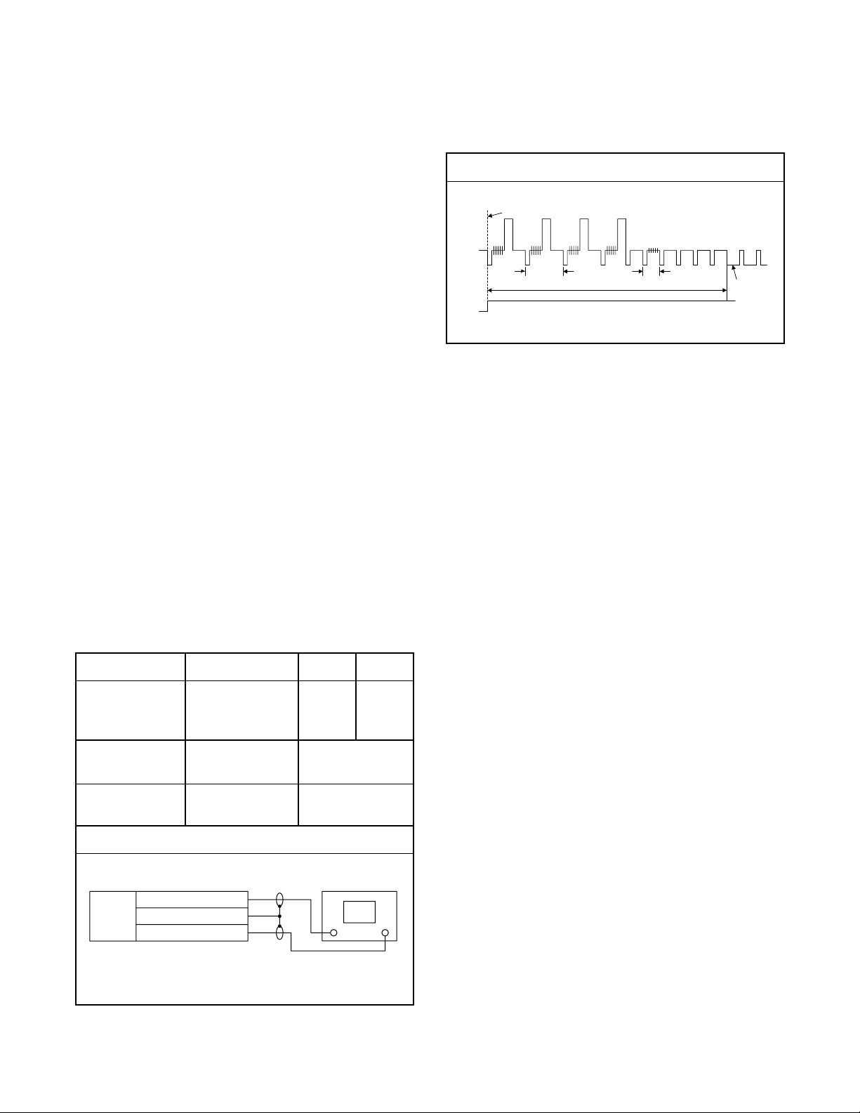
4-3 ELECTRICAL ADJUSTMENT INSTRUCTIONS
General Note: "CBA" is an abbreviation for
"Circuit Board Assembly."
NOTE:
1.Electrical adjustments are required after replacing
circuit components and certain mechanical parts.
It is important to do these adjustments only after
all repairs and replacements have been completed. Also, do not attempt these adjustments
unless the proper equipment is available.
2.To perform these alignment / confirmation procedures, make sure that the tracking control is set in
the center position: Press either "CHANNEL L5??" or
"CHANNEL K" button on the front panel first, then
the "PLAY" button on the front panel.
EXT. Syncronize Trigger Point
CH1
1.0H
CH2
Figure 1
6.5H
Switching Pulse
0.5H
V-Sync
4-3-1 Test Equipment Required
1.Oscilloscope: Dual-trace with 10:1 probe,
V-Range: 0.001~50V/Div.,
F-Range: DC~AC-20MHz
2.Alignment Tape (MH-1)
4-3-2 Head Switching Position
Adjustment
Purpose:
To determine the Head Switching point during
playback.
Symptom of Misadjustment:
May cause Head Switching noise or vertical jitter
in the picture.
Test point Adj.Point Mode Input
TP751(V-OUT)
TP302(RF-SW)
J20(GND)
Tape
VR501
(Switching Point)
(MAIN CBA)
Measurement
Equipment
PLAY
(SP)
Spec.
Reference Notes:
Playback the Alignment tape and adjust VR501 so that
the V-sync front edge of the CH1 video output waveform is at the 6.5H(412.7µs) delayed position from the
rising edge of the CH2 head switching pulse waveform.
-----
MH-1 Oscilloscope
Connections of Measurement Equipment
Main
CBA
TP751(V-OUT)
J20(GND)
TP302(RF-SW)
6.5H±1H
(412.7µs±60µs)
Oscilloscope
CH1 CH2
Trig. (+)
4-3
 Loading...