

Page 1

TABLE OF CONTENTS
HITACHI
Instruction Manual
8mm Video Camera/Recorder
VM-H38A
Hitachi Home Electronics (America), Inc. HITACHI (HSC) CANADA INC.
3890 Steve Reynolds Blvd., Norcross, GA 30093 3300 Trans Canada Highway, Pointe Claire,
Tel. 404-279-5600 Quebec, H9R 1B1, CANADA
Tel. 514-697-9150
HITACHI SALES CORPORATION OF
HAWAII, INC.
3219 Koapaka Street, Honolulu, Hawaii 96819
Tel. 808-836-3621
E145554/E72118
P4707229 © Hitachi, Ltd. 1992 Printed in Japan KF-TF(N)
1
Page 2

TABLE OF CONTENTS
TABLE OF CONTENTS
TABLE OF CONTENTS............................................................................................................................2
IMPORTANT SAFEGUARDS.....................................................................................................................3
FEATURES .................................................................................................................................................5
ACCESSORIES ..........................................................................................................................................5
IMPORTANT SAFEGUARDS.....................................................................................................................6
IMPORTANT SAFETY INSTRUCTIONS FOR AC ADAPTER/ CHARGER...............................................9
Hi8 .............................................................................................................................................................10
ELECTRONIC VIEWFINDER (EVF) POSITION ADJUSTMENT ............................................................10
HOW TO ATTACH THE SHOULDER STRAP.........................................................................................11
LOADING BATTERIES FOR DATE/TIME AND REMOTE CONTRO L ...................................................11
POWER SOURCES..................................................................................................................................12
CHECKING THE BATTERY .....................................................................................................................13
CHARGING THE BATTERY.....................................................................................................................15
INSERTION AND REMOVAL OF CASSETES ........................................................................................16
MAKING A SAMPLE CAMERA RECORDING.........................................................................................17
IDENTIFICATION AND OPERATION OF CONTROLS ........................................................................... 19
DATE/TIME SETTING ..............................................................................................................................22
AUTO FOCUS...........................................................................................................................................24
EXPOSURE CORRECTION.....................................................................................................................25
POWER ZOOM.........................................................................................................................................26
DIGITAL ZOOM.........................................................................................................................................27
FADE-IN/FADE-OUT ................................................................................................................................28
DIGITAL FILTER.......................................................................................................................................29
ELECTRONIC IMAGE STABILIZER (EIS)...............................................................................................30
MACRO.....................................................................................................................................................31
SECOND CLOCK SETTING.....................................................................................................................32
DISPLAY BUTTON...................................................................................................................................33
LINEAR TIME COUNTER.........................................................................................................................33
MEMORY ..................................................................................................................................................34
INSTANT REVIEW.................................................................................................................................... 35
QUICK EDIT..............................................................................................................................................35
EYEPIECE ADJUSTMENT.......................................................................................................................36
TITLE RECORDING .................................................................................................................................36
WIRELESS REMOTE CONTROLLER.....................................................................................................39
AUDIO/VIDEO DUBBING.........................................................................................................................40
RECORDING TV PROGRAMS ................................................................................................................41
VIEWING THE PICTURE PLAYED BACK ON YOUR TV.......................................................................42
STILL.........................................................................................................................................................44
FORWARD AND REVERSE SEARCH ....................................................................................................44
ATTACHING THE TELE OR WIDE CONVERTER..................................................................................45
CAMERA/RECORDER TO VCR DUBBING.............................................................................................45
FLYING ERASE HEAD.............................................................................................................................46
PROGRAMME AE (Auto Exposure).........................................................................................................46
SYNCHRO EDIT.......................................................................................................................................46
ATTACHING THE OPTIONAL DC CAMERA LIGHT (VM-CP4).............................................................. 48
TROUBLESHOOTING..............................................................................................................................50
HEAD CLEANING.....................................................................................................................................51
PERIODIC MAINTENANCE .....................................................................................................................51
SPECIFICATIONS ....................................................................................................................................52
ACCESSORY TO ADD MORE EXCITEMENT ........................................................................................53
HOW TO ORDER......................................................................................................................................53
2
Page 3
IMPORTANT SAFEGUARDS
IMPORTANT SAFEGUARDS
WARNING: TO PREVENT FIRE O R SHOCK HAZARD, DO NOT EXPO SE THIS UNIT TO
RAIN OR MOISTURE.
CAUTION: TO REDUCE THE RISK OF ELECTRIC SHOCK, DO NOT REMOVE COVER (OR
BACK). NO USER-SERVICEABLE PARTS I NSIDE.
REFER SERVICING TO QUALI F IED SERVICE PERSONNEL.
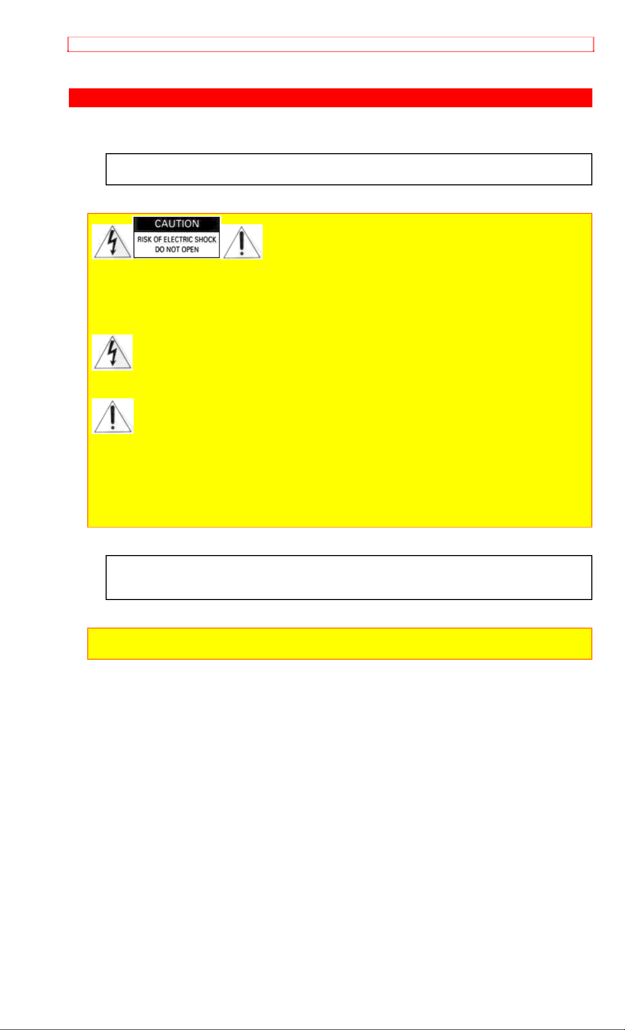
This symbol warms the user that uninsulated voltage within the unit m ay have sufficient
magnitude to cause electric shock. Therefore, it is danger ous t o m ake any kind of contact with any
inside part of this unit.
This symbol alerts the user that impor t ant literature concerning the operat ion and
maintenance of this unit has been included. T her efore, it should be read caref ully to avoid any
problems.
CAUTION: TO PREVENT ELECTRIC SHOCK, MATCH WIDE BLADE OF PLUG TO WIDE SLOT,
FULLY INSERT
This digital apparatus does not exceed the Class B limits for radio noise emissions from digital
apparatus set out in the Radio Interference regulations of the Canadian Depar tment of
Communications.
Caution to the user: Changes or modifications not expressly approved by the party responsible for
compliance could void the user's authority to operate the equipment.
3
Page 4
IMPORTANT SAFEGUARDS
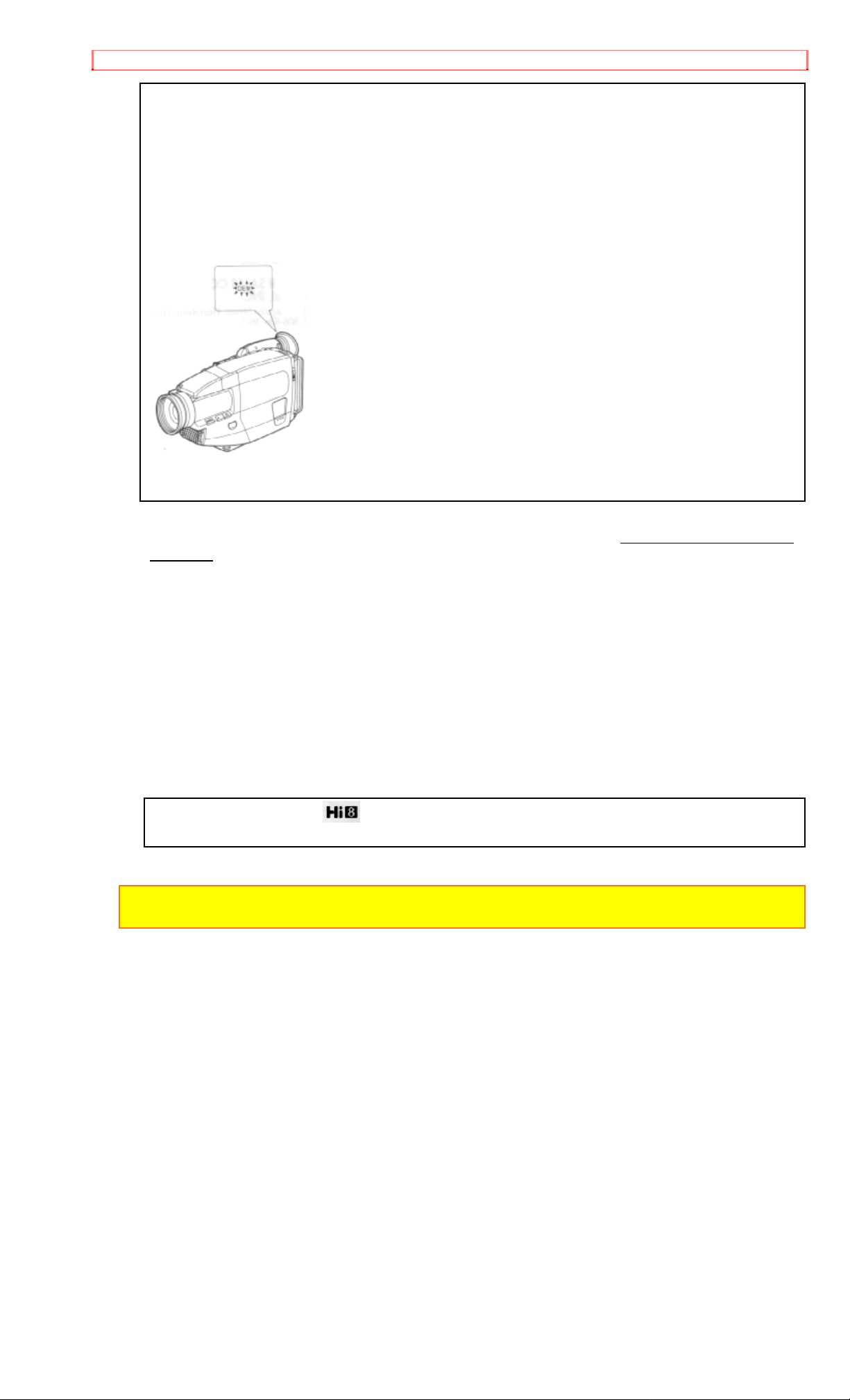
MOISTURE
Moisture may occur if the video camera/recorder is moved f r om a cold area to a warm humid
area. A flashing "DEW" indication in the viewfinder indicates that moisture has condensed on
the recorder mechanism, which could result in tape damage. Since condensation builds up
gradually, the indication does not appear immediately when condensation start s. When the
temperature or humidity of t he room changes abruptly, turn the power on and check that the
"DEW" indication does not appear, then wait for about an hour for safety before using the
camera/recorder. When the "DEW" indication in the viewfinder is flashing the unit will not
operate. When this happens, slide the "EJECT" switch, remove the tape, and wait for the
moisture to dry... the "DEW" indication in the viewfinder will stop flashing.
PRECAUTIONS
Any problems that occur as a result of any of t he following conditions will not be covered by our
warranty.
Be careful that no water, dust or sand enter s t he cam era/recorder.
When you are not using t he cam er a/recorder, switch off the power and att ach t he lens cap.
When you shoot at a scene which contains an extremely bright object such as the sun or a
light source, a bright vertical bar may appear in the picture. Your camera/r ecor der is functioning
properly, but the solid-state pickup device (C.C. D. ) usually causes this as an inher ent
characteristic. Try to avoid shooting an excessively bright object directly.
Be sure not to leave it in a place where the temperature exceeds 120ºF, or t he pickup device
may be damaged. Dangerous includes:
• Inside a car with the windows closed and in direct sunshine.
• Near heating appliances.
Do not leave the viewfinder lens facing sunlight for a prolonged period, or the phosphorescent
surface of the cathode ray tube m ay be damag ed.
Thank you for buying the
video camera/recorder. For maximun pleasure and convenience
please read these simple instructions before operating your camera/recorder.
WARNING: Many television programs and films are copyrighted. In cer t ain circumstances,
copyright law may apply to private in-home video taping of copyrighted mat er ials.
4
Page 5
FEATURES
FEATURES
• Hi8 • Fade-in/Fade-out
• Electronic Image Stabilizer (EIS) • Auto Focus Power Zoom Lens with macro feature
• Digital Filter • Flying Erase Head
• Digital Zoom up to X16 • Time and date
• Solid-state camera pickup • Titler
• Program AE (Auto Exposure) • Wireless Remote Control
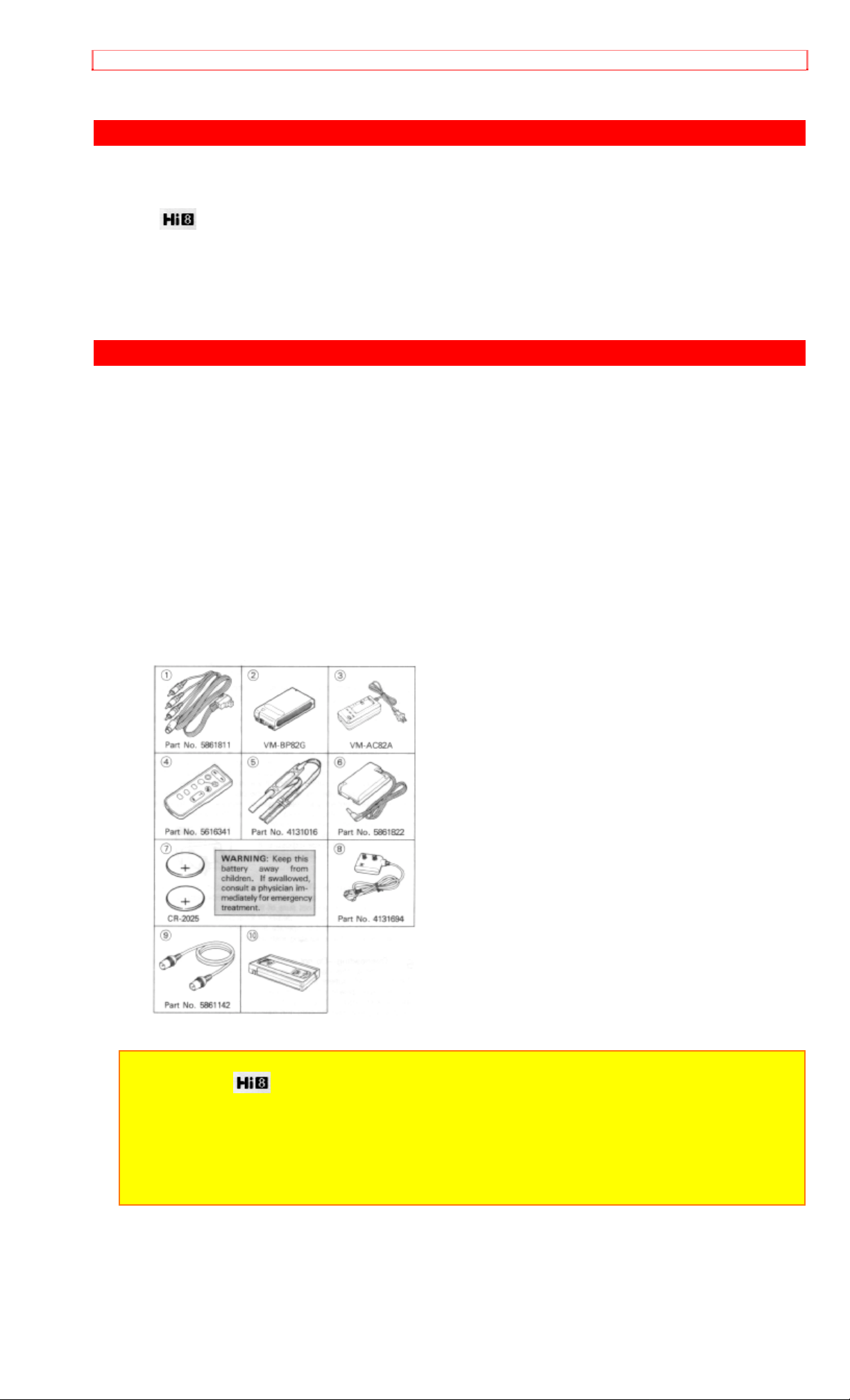
ACCESSORIES
Check that you have the following components and accessories (besides the camer a/ r ecor der
unit itself) befor e disposing of the packing material.
1. AV Stereo Output Cord with S plug
2. Battery Pack
3. AC Adapter/Charger
4. Wireless Remote Controller
5. Shoulder Strap
6. External Power Adapter
7. Batteries for Date/Time and Wireless Remote Controller
8. RF Output Adapter
9. 75-ohm Coaxial Cable
10. Video Owner's Manual
• This is a VHS cassette tape which includes instruction on how to operate your VM-H38A
camera/recorder.
This tape covers the basic operations of this model and some ideas on how to make better
recordings.
NOTES:
• This unit uses video format cassettes.
• It records and plays back in the SP mode (14.3 mm /sec.).
• It cannot record and play back in the LP mode (7.2 m m/sec.).
• This camera/recorder uses a Hi-Fi ster eo sound system . When a tape recorded by this
camera/recorder is played by a conventional 8mm camera/recorder , monaural sound is output.
When a tape recorded by a conventional 8mm camera/recorder is played by this machine,
monaural sound is output.
5
Page 6
IMPORTANT SAFEGUARDS
IMPORTANT SAFEGUARDS
In addition to the careful att ent ion devoted t o quality standards in the manufacture of your video
product, safety is a major factor in the design of every instrument. But, safety is your
responsibility too.
This page lists important information that will help to assure your enjoyment and pr oper use of a
Video Camera/Recorder and accessory equipment. Please r ead it carefully before operating
your video product and keep it in a handy place for futur e r eference.
1 Read and Follow Instructions -- All the safety and operating inst ructions should be read
before the video product is operated. Follow all operating and use inst r uctions.
2 Retain Instructions -- The safety and operating inst r uct ions should be r etained for future
reference.
3 Heed Warnings -- Comply with all warnings on the video product and in the operating
instructions.
4 Polarized Plug -- This video product is eq uipped with a polarized alter nat ing-current line plug
(a plug having one blade wider than the other). T his plug will fit into the power outlet only one
way. This is a safety feature. If you are unable to insert the plug fully into the outlet, try reversing
the plug. If the plug should still fail to fit, contact your electrician to replace your obsolete outlet.
To prevent electric shock do not use this polarized plug with an extension cord, r ecept acle or
other outlet unless the blades can be fully inserted without blade exposure. I f you need an
extension, use a polarized cord.
INSTALLATION
5 Power Sources -- This video product should be operated only from the type of power source
indicated on the marking label. I f you are not sure of the type of power supply to your home,
consult your video dealer or local power company. For video products intended to operate from
battery power, or other sources, refer to the operating instructions.
6 Overloading -- Do not overload wall outlets and extension cords as this can result in a risk of
fire or electric shock. O verloaded AC out let s and extension cords are dangerous, and so are
frayed power cords, damaged or cracked wire insulation and broken plugs. They may result in a
shock or fire hazard. Periodically examine the cord and have it replaced by your service
technician if appearance indicates damage or det er ior ated insulation.
7 Power-Cord Protection -- Power-supply cords should be r out ed so t hat they are not likely to
be walked on or pinched by items placed upon or against them, paying par t icular at tention to
cords at plugs, convenience receptacles, and the point where they exit fr om the appliance.
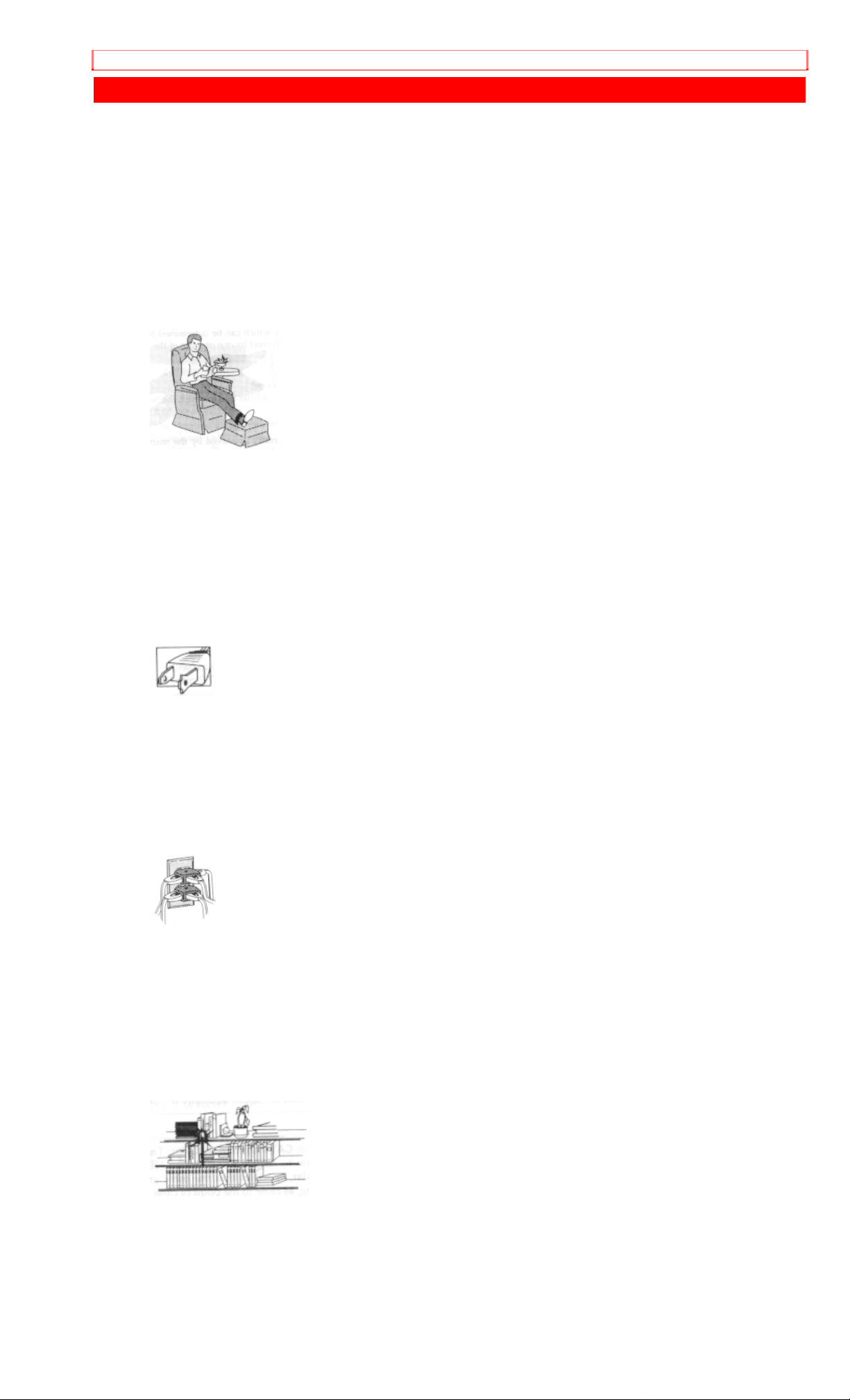
8 Ventilation -- Slots and openings in the cabinet are provided for ventilation to ensure reliable
operation of the video product and to protect it from overheating. These openings must not be
blocked or covered. The openings should never be blocked by placing t he video product on a
bed, sofa, rug or ot her sim ilar surface. This video product should never be placed near or over a
radiator or heat register. This video product should not be placed in a built-in installation such as
a bookcase or rack unless proper ventilation is provided or the video product m anufacturer's
instructions have been followed.
9 Attachments -- Do not use attachments unless recommended by the video product
manufacturer as they may cause hazards.
6
Page 7

IMPORTANT SAFEGUARDS
Caution: Maintain electrical safety. Powerline operated eq uipm ent or accessories connected to this
unit should bear the UL listing mark or CSA certification mark on the accessory itself and should not
have been modified so as to defeat the safety features. This will help avoid any potential hazard
from electric shock or fire. If in doubt, cont act qualified service personnel.
10 Water and Moisture -- Do not use this video product near water - for example, near a bath
tub, wash bowl, kitchen sink, or laundry tub, in a wet basement, or near a swimming pool, and
the like.
11 Accessories -- Do not place this video product on an unstable card, stand, tripod, brack et ,
or table. The video product may fall, causing serious injury to a child or adult, and serious
damage to the appliance. Use only with a cart, stand, tr ipod, bracket, or table recomm ended by
the manufacturer, or sold with the video product. Any mounting of the product should follow the
manufacturer's instruct ions, and should use a mounting accessory recommended by the
manufacturer.
11A An appliance and cart combination should be moved with care. Quick stops, excessive
force, and uneven surfaces may cause the appliance and cart com binat ion to overturn.
12 Outdoor Antenna Grounding -- If an outside antenna or cable system is connected to the
video product, be sure the antenna or cable system is grounded so as to provide some
protection against voltage surges and built-up static charges. Section 810 of the National
Electrical Code, ANSI/NFPA No. 70, provides inf or mation with respect to proper grounding of
the mast and supporting structur e, grounding of the lead-in wire to an ant enna dischar ge unit,
size of grounding conductors, locat ion of antenna-discharge unit, connection t o grounding
electrodes, and requirements for the grounding electr ode. See example below:
EXAMPLE OF ANTENNA GROUNDING
13 Power Lines -- An outside antenna system should not be located in the vicinity of overhead
power lines or other electric light or power circuits , or where it can fall into such power lines or
circuits. When installing an outside antenna system, extreme car e should be t aken to keep from
touching or approaching such power lines or circuits as cont act with them m ight be fatal.
Installing an outdoor antenna can be hazardous and should be left to a professional antenna
installer.
USE
14 Cleaning -- Unplug this video product from the wall outlet before cleaning . Do not use liquid
cleaners or aerosol cleaners. Use a damp cloth for cleaning.
15 Object and Liquid Entry -- Never push objects of any kind int o t his video product through
openings as they may touch dangerous voltage points or short - out parts that could result in a
fire or electric shock. Never spill liquid of any kind on the video product.
16 Lightning -- For added protection for this video product during a lightning storm, or when it
its left unattended and unused f or long periods of time, unplug it from the wall outlet and
disconnect the antenna or cable-system. This will prevent damage t o the video product due to
lightning and power-line surges.
7
Page 8

IMPORTANT SAFEGUARDS
17 Servicing -- Do not attempt t o ser vice this video product yourself as opening or removing
covers may expose you to dangerous voltage or other hazards. Refer all ser vicing t o qualified
service personnel.
18 Conditions Requiring Service -- Unplug this video product from the wall outlet and refer
servicing to qualified service personnel under t he following conditions.
a. When t he power-supply cord or plug is damaged
b. If liquid has been spilled, or obj ects have fallen into the video product.
c. If the video product has been exposed to rain or water.
d. If the video product does not operate nor m ally by following the operating instructions. Adjust
only those controls that are covered by the operating instruct ions. Improper adjustment of other
controls may result in damage and will often r equire extensive work by a qualified technician to
restore the video product to its normal operation.
e. If the video product has been dropped or the cabinet has been dam aged.
f. When the video product exhibits a distinct change in perf or m ance - this indicates a need for
service.
19 Replacement Parts -- When replacement parts are required, have the service technician
verify that the replacements he uses have the same safet y charact er ist ics as t he or iginal parts.
Use of replacements specified by the video product manufacturer can prevent fire, elect r ic
shock or other hazards.
20 Safety Check -- Upon completion of any service or repairs to this video product, ask the
service technician to perform saf et y check s r ecom m ended by the m anufacturer to determine
that the video product is in safe operating condit ion.
SERVICE
8
Page 9

IMPORTANT SAFETY INSTRUCTIONS FOR AC ADAPTER/CHARGER
IMPORTANT SAFETY INSTRUCTIONS FOR AC ADAPTER/CHARGER
1. Save these instructions -- This page cont ains im por tant safety and operating instructions for
AC Adapter/Charger Model VM-AC 82A.
2. Before using AC Adapter/ Char ger, read all instructions and cautionary mar kings on (1) AC
Adapter/Charger, (2) bat tery and (3) product using battery.
3. Also read all instructions on pages 4 and 5.
4. Caution -- To reduce r isk of injury, charge only rechargeable battery, VM-BP82G or VM-BP82.
Other types of batteries may burst causing personal injury and damage.
5. Do not expose charger to rain or snow.
6. Use of an attachment nor recommended or sold by the battery charger manuf acturer may
result in a risk of f ir e, electric shock, or injury to persons.
7. To reduce risk of dam age to electric plug and cord, pull by plug rat her t han cord when
disconnecting charger.
8. Make sure cord is located so that it will not be stepped on, tr ipped over, or otherwise
subjected to damage or stress.
9. Do not operate charger with damaged cor d or plug - replace them immediately.
10. An extension cord should not be used unless absolutely necessary.
Use of improper extension cord could result in a risk of fire and electric shock. If extension cord
must be used, make sure:
A. The pins on plug of extension cord are t he sam e num ber , size, and shape as those of plug
on charger.
B. That extension cord is properly wired and in good electrical condition; and
C. That wire size should be met below:
Minimum
AWG size Length of extension cord (f eet)
18 Equal to or less than 100
16 Equal to or less than 150
11. Do not operate charger if it has received a sharp blow, been dropped, or otherwise
damaged in any way; take it to a qualif ied ser viceman.
12. Do not disassemble charger: take it to a qualified serviceman when service or repair is
required. Incorrect r eassem bly may result in a r isk of electric shock or fire.
13. To reduce risk of elect r ic shock, unplug charger f r om outlet before attempt ing any
maintenance or cleaning.
"Note to CATV system installer: This reminder is provided to call the CATV system installer's
attention to Article 820-40 of the NEC that provides guidelines for proper grounding and, in
particular, specifies that the cable ground shall be connected to the grounding system of the
building, as close to the point of cable ent r y as pract ical" .
9
Page 10
Hi8
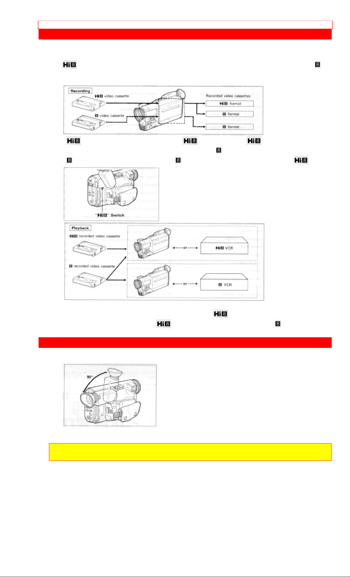
Hi8
format.
Compatibilty with conventional video camera/recorder
•
camera/recorder is set to "AUTO", and r ecor ded in t he
•
has realized high resolution and high picture qualit y when compared to t he st andar d
video cassettes are recorded in the format when the switch of this
format when it is set to "OFF".
video cassettes are recorded in the format regardless of the position of the switch.
• During playback, the recording format is discriminated automatically and video cassettes are
played back correctly regardless of t he posit ion of the
• Video cassettes recorded in the
format cannot be played back by an VCR.
ELECTRONIC VIEWFINDER (EVF) POSI TIO N ADJUSTMENT
• Adjust the electronic viewfinder to a position where you can see through it easily.
switch.
NOTE: Put the viewfinder back to the orig inal position when storing the camera/recorder int o the
carrying case or carrying the camera/recorder.
10
Page 11
HOW TO ATTACH THE SHOULDER STRAP
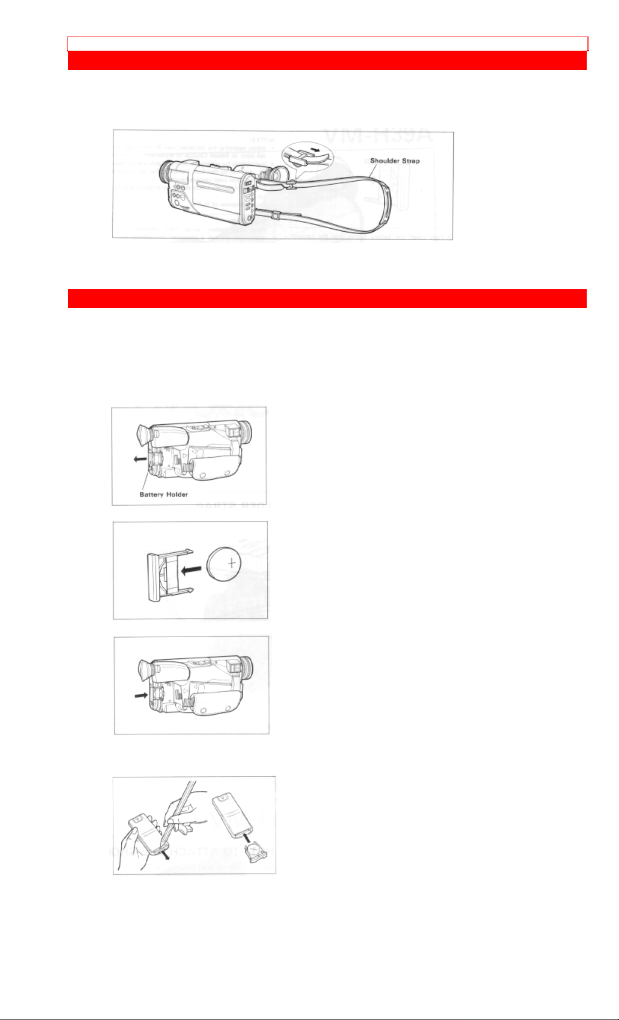
HOW TO ATTACH THE SH OULDER S TRAP
Attach the shoulder strap (provided), as illustr at ed.
LOADING BATTERIES FOR DATE/TIME AND REMOTE CONTROL
You may want to install the date/time and remote cont r ol batteries (provided) immediately to
prevent misplacing them.
For date/time
1. Pull the battery holder.
2. Insert the date/time bat tery with the "+" terminal facing up.
3. Fully insert the battery hjolder into the cam er a / r ecor der.
For remote control
1. Pull the battery holder from the remote control (provided).
2. Place the battery as illustrated, and then at tach the holder to the remote contr ol.
11
Page 12
POWER SOURCES
NOTES:
• When replacing the batteries, use 3V micro lithium cell such as Maxell CR2025 or equivalent.
• Instructions for sett ing the date and time are on page 22. You can do that lat er if desired after
you're more familiar with your camera/r ecor der .
• Dispose of battery safely and in accordance with local laws.
• Do not dispose of in fire.
WARNING:
Keep this battery away from children. If swallowed, consult a physician immediately f or emergency
treatment.
POWER SOURCES
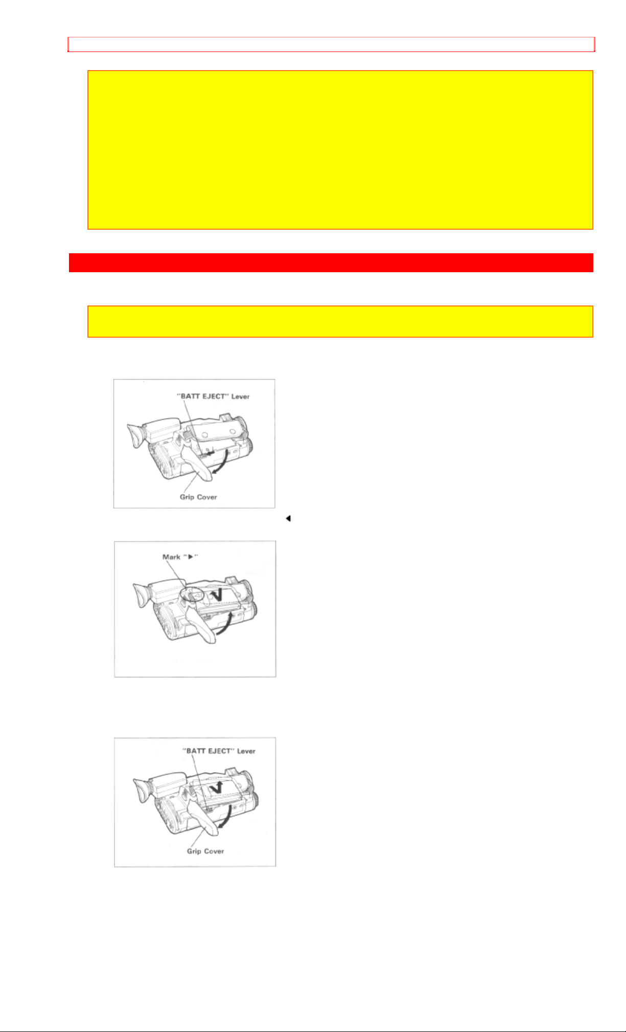
WHEN US ING WITH THE BATTERY (provided)
NOTE: The battery must be charged before it can be used for the first time. Refer t o "CHARGING
THE BATTERY" on page 14.
1. Push the "BATT EJECT" lever in the direction of the arrow and hold it, then open the grip
cover.
2. To attach the battery, align the "
" mark on the battery with that of the camera/recorder.
3. Hold the battery flush against the camera/recorder and slide it in the direction of the arrow.
4. Close the grip cover.
To remove the battery
1. Push and hold "BATT EJECT" lever, then open the grip cover.
2. Slide the battery downward and off.
12
Page 13
CHECKING THE BATTERY
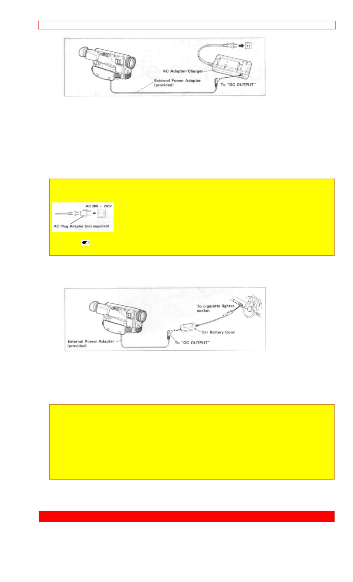
WHEN USING WITH THE AC ADAPTER/CHARGER (provided)
1. Plug the AC adapter/charg e r power cord int o an AC electrical output; the "POWER" indicat or
on the AC adapter/charger will come on.
2. Attach the external power adapter (provided) to the camer a/recorder as shown in the figure.
Align the marks and hold the external power adapter flush against the camera/recor der . Then
attach it using the same procedure used when attaching the battery.
3. Connect the external power adapter plug to the "DC OUTPUT" jack of the AC
adapter/charger.
4. To remove the external power adapter from the camera/recorder, perform the same
procedure as when removing the battery.
NOTES:
• This AC adapter/charger is universal ar ound t he world. I f you use the camera/recorder in some
foreign countries, an AC plug adapt er (not supplied) may be necessary.
• When using the AC adapter/charger to power the camera/recorder, the battery level indicator m ay
display " " . This indicator is used for battery operation and has no meaning when using the Ac
adapter/charger to power the camera/ recorder.
WHEN USING WITH THE CAR BATTERY (by using optional car battery cord Hitachi VMCC80A)
1. Connect the car battery cord to the car' s cigarette lighter socket.
2. Connect the external power adapter (provided) to the camera/recorder, as illustrated.
• Attach it by the same procedure as when attaching the battery.
3. Connect the small plug of t he exter nal power adapter t o "DC OUTPUT" of the car battery
cord.
NOTES:
• The car battery cord is designed to be used only with automobiles having a 12/24- volt negative
ground system.
• To prevent fire or shock hazard or dam age to your camera/recorder, please use only Hitachi's car
battery cord model VM-CC80A.
NOTE: Be sure to set the power switch to "OFF" position when attaching or detaching a power
supply (battery, AC adapter/charger, et c.) to the camera/recorder.
CHECKING THE BATTERY
13
Page 14
CHECKING THE BATTERY
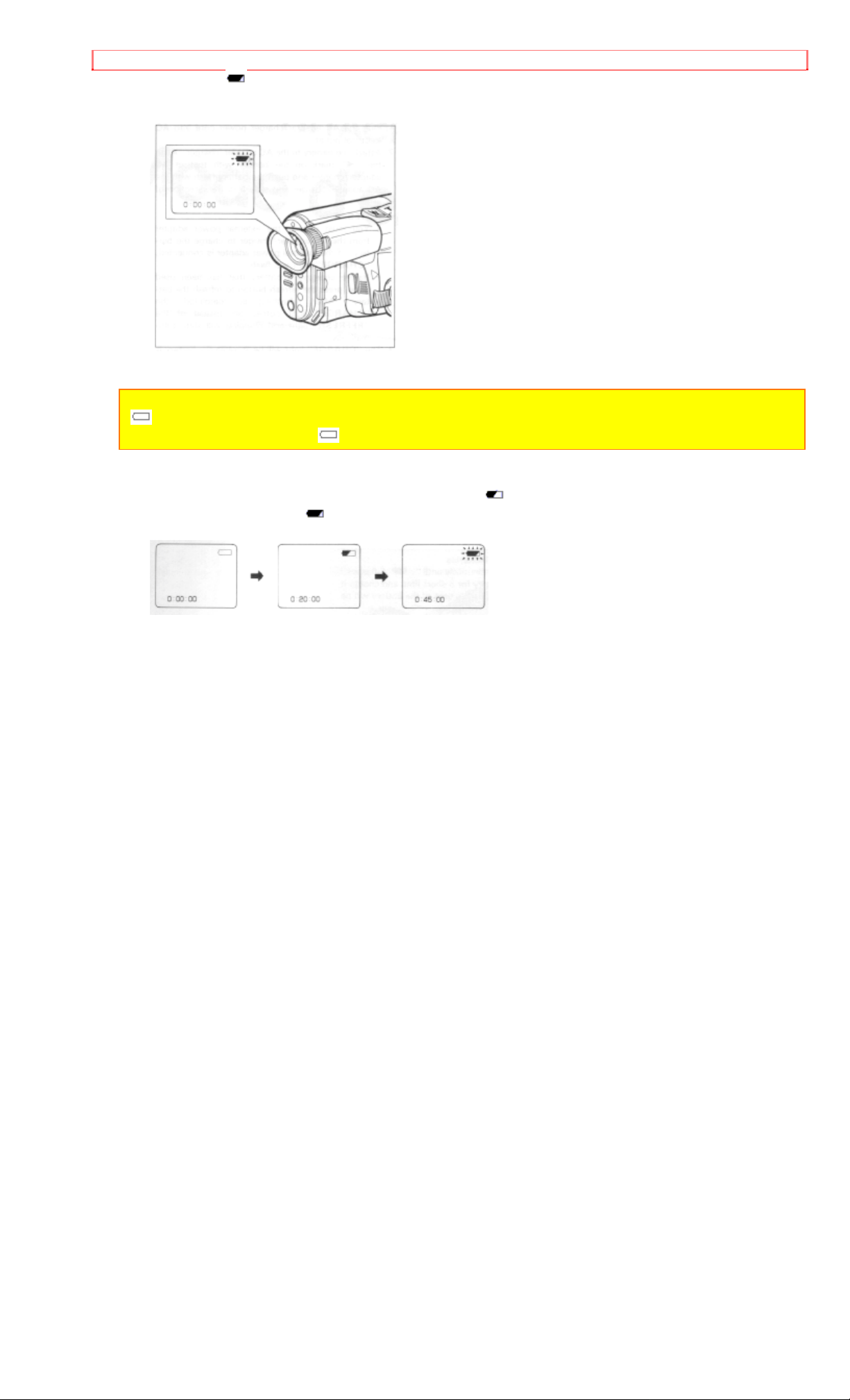
When the " " indication appears in the viewfinder and flashes while the camera/recorder is
being operated with a battery (provided), it indicates t hat the battery charge is low. Charge it or
replace it with a charged battery.
NOTE: Whenever t he linear time counter is present in the viewfinder, the batt er y level indicator
" " is displayed in the viewfinder indicating the condition of camera/recorder battery power. When
the battery is fully charged, " " is displayed.
After several minutes, the symbol will change to " ". When the battery is very near empty, the
symbol will change to "
" and start blinking. You should find an alternative power source or
recharge the battery befor e cont inuing to use your camera/recorder.
14
Page 15

CHARGING THE BATTERY
CHARGING THE BATTERY
1. Plug the AC adapter/charger power cord into AC electrical outlet.
2. Attach the battery to the AC adapt er /charger. Align the "
" mark on the battery with that of
AC adapter/charger and push the battery flush with the AC adapter/charger and slide it in the
direction of arrow.
NOTES:
• You must remove the external power adapter from the AC adapter/charger to charge the battery. If
the external power adapter is connected, "CHARGE" light will flash.
• Before charging a battery that has been used once, press the refresh button to refresh the battery.
After refr eshing is completed, the "CHARGE" light comes on instead of the "REFRESH" light and
charging will start automatically.
3. The "CHARGE" light will be lit while the battery is accepting a charge, and will go out when
the battery is fully charged.
Skillful use of batteries
Use batteries continuously until " " flashes. If you use a battery for a short time and charge it
immediately, the usable time of t he bat tery will be shortened.
NOTES:
1. The time required for charging the battery is approx. one hour.
2. When fully charged, the battery should supply approx. 50 minutes of oper ating time (depending
on how much you use zoom and pause).
3. If you repeatedly charge a batter y which is not completely discharg ed the useable time of the
battery will become shorter. Refresh such a battery before charging it.
4. It takes about 4 hours to r efresh a fully charged batter y (VM-BP82G).
5. Charge the battery before use and store it at normal room tem per ature.
6. The battery should be charged at a tem per at ur e of 32°F - 95°F (0°C - 35°C) to prevent damag e.
7. Do not operate the battery at temperatures below 14°F (-10°C) or above 95°F (35°C). The battery
may be damaged if operated at temperatures above 122°F (50°C). Operation time will decrease at
extremely low temperatures.
8. After repeated shargings and use, the operation time will gradually decrease. When operation
time becomes too short to be useful, it is time to replace the battery.
9. If the "POWER" light on the AC adapter/char ger starts flashing, remove the battery and then
reattach it. If after several attempts the "POWER" light contimues to flash, this means your battery
cannot take a charge and must be replaced with a new one. The "POWER" light will also flash it a
hot battery is attached to the AC adapter/charger. Attaching an extr em ely hot battery to the AC
adapter/charger is not recom m ended; it should be allowed to cool down before being attached.
10. Do not short the battery's terminal.
11. Do not attempt to disassemble or modify the battery. There are no user serviceable parts inside.
12. Throwing the battery into a fire or exposing the battery to excessive heat - over 149°F (65°C)
could be hazardous.
13. Set the mark switch of any batter y which has already been charged to r ed as shown in the
figure. This lets you discrim inat e between charged and uncharged batteries easily.
15
Page 16
INSERTION AND REMOVAL OF CASSETES
INSERTION AND REMOVAL OF CASSETES
Before inserting or rem oving a casset t e, be sure to connect the power source. When a power
source is connected, the cassette can be ejected and rem oved whether the power is on or off.
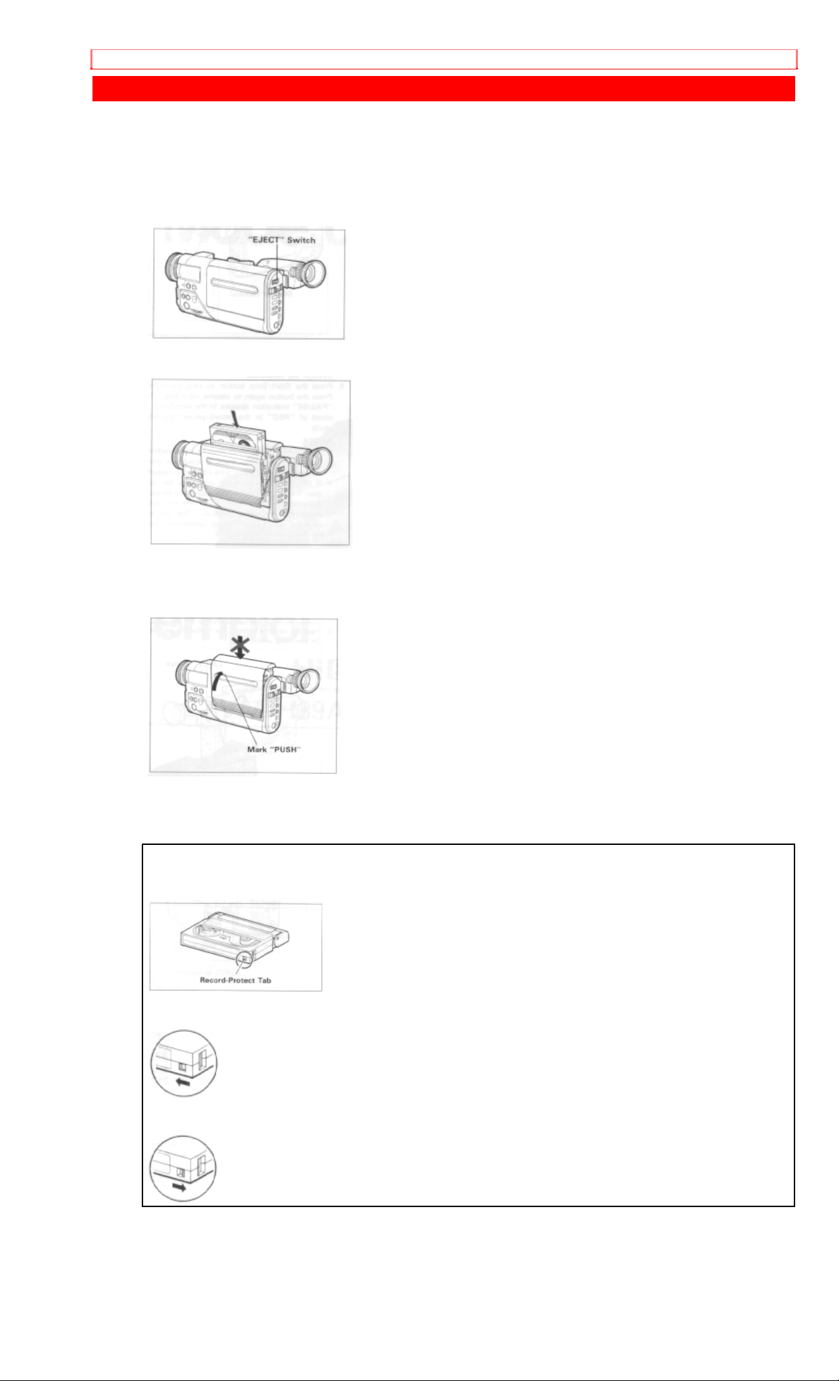
Insertion
1. Slide the "EJECT" switch.
The cassette door will open.
2. Insert a cassette so the transparent window is toward you and the arrow toward the cassette
holder. Slide the cassette into cassette holder as far as it will go.
3. Press the cassette holder.
Push the section of the holder marked "PUSH" until a click is heard.
The camera/recorder will automatically close the top of the cassette compartment. D o not
press the door down, or you may damage your camera/recorder.
Removal
Slide the "EJECT" switch and remove the cassette.
8mm Video Cassette
An 8mm Video Cassette has a record-protect t ab on t he side of the cassette that can be slid to
prevent accidental erasure of recorded mat er ial.
To prevent accidental erasure, slide the record-protect tab in the direction of the arrow until the
red tab is completely visible.
To record on the cassette again, slide the record-protect tab in the direct ion of the arrow. The
red tab will disappear behingd the cassette case.
16
Page 17

MAKING A SAMPLE CAMERA RECORDING
MAKING A SAMPLE CAMERA RECORDING
1. Connect the POWER SOURCE. (See pages 11 and 12.)
2. Slide "EJECT" switch and insert tha cassette so the transparent window is toward you and
the arrow toward the cassette holder. Slide the cassett e int o cassette holder as far as it will go.
NOTE: If the power source is not connected to the camera/recorder, the cassett e holder will not
open.
3. Press the cassette holder. The holder will latch in the operating position.
4. Set the "
" switch to "AUTO".
5. Slide the power switch to "CAMERA". The camera/recorder will enter record/pause mode
automatically.
NOTES:
• If the red record-prot ect tab on the cassette is closed, the "TAPE" indication in the viewfinder
flashes for several seconds and the camera/r ecorder will not enter the record/pause mode.
6. Now, press the Start/Stop button t o st art shooting the picture. "REC" indication appears in the
viewfinder. You are now recording the picture you see through the viewfinder.
7. Press the Start/Stop butt on t o stop recording. Press the button again to resume recording.
The "PAUSE" indication appears in the viewfinder instead of "REC" in the record/pause ( s t andby) mode.
NOTES:
• The "TAPE END" indication in the viewfinder starts flashing when there is less than about three
minutes recording time lef t on the cassette.
• If the record/pause mode continues for more than 5 minutes, the cam er a/recorder's power is
automatically turned off. To turn on again, press the Star t / St op button. The camera/recorder ent ers
record/pause (stand-by) mode.
8. After recording , slide the power switch to "VIDEO", and the camera/ r ecor der will now be in
the stop mode.
9. Press "REW" button. The tape will be rewound to the beginning.
10. Press "PLAY" button. The picture you just recorded will be seen through the viewfinder.
17
Page 18

MAKING A SAMPLE CAMERA RECORDING
NOTE: If you connect the camera/r ecor der t o your TV, you can see the picture played back on your
TV. Refer to "VIEWING THE PICTURE PLAYED BACK ON YOUR TV" on page 37.
11. After playing, press "STOP" but ton.
12. Slide the power switch to "OFF" and then slide "EJECT" switch to remove cassette.
13. Always remove the power source from the camera/recorder after use. See "POWER
SOURCES" on page 11.
NOTE: If you have a cassette tape that has already been partially recorded on and you want to
record the remaining blank sect ion, see " QUICK EDIT" on page 31.
18
Page 19

IDENTIFICATION AND OPERATION OF CONTROLS
IDENTIFICATION AND OPERATION OF CONTROLS
Left side Illustration
1. Lens
F1.4 (6~48mm) 8:1 power zoom lens features auto focus and auto iris functions.
2. "ZOOM MODE" Button
Use this button to switch the digital zoom feature. Usually press this button so that "ZM:1"
appears in the viewfinder. (See "DIGITAL ZOOM" on page 25.)
3. "EIS" (Electronic Image Stabilizer) Button
Press to display (hand) in the viewfinder. EIS corrects slig ht shaking of the image to be
recorded.
4. "B. (Back) LIGHT" Button
When the subj ect is lit from behind, press and hold this butt on t o com pensate for the backlighting.
5. Cassette Holder
Slide "EJECT" switch to open the cassette holder. Be aware of the cassett e dir ection when
inserting.
NOTE: Power source must be connected to open the cassette holder.
6. "FADE" Button
During recording you can add a professional touch to your recordings by fading in and out of
scenes. You can select the three fade modes - the white fade, wipe fade and zoom fade.
7. Focus Control
For manual focusing, rotate this control to bring the subject into focus.
8. "FOCUS" Select Butt on
Press this button to switch between automatic and manual focusing. If this buttons is pr essed
and "FOCUS M." appears in the viewfinder, the camera/recorder enters the manual focus mode.
When "FO CUS M . " is not displayed, focusing is automatic.
9. "D.FILTER (Digital Filter) Button
Press for a special-effect recording by changing the tone. If you press this button to display
"(???)" in the viewfinder and start recording, for example, the pictur e will be recorded in sepia.
10. Stereo Microphone
Sensitive to source coming from t he dir ection in which the camera is pointed.
11. Infrared Ray Receiver
Receives infrared rays from the r emote control (provided).
12. Record Indicator
This indicator lights up to indicate t hat the camera/recorder is recording.
13. Eye Cup
Pull out the eye cup all the way when using it and adjust the diopter control so that the subject is
seen most clearly in the viewfinder.
Always push in the eye cup after use.
Right side/Rear Illustrat ion
14. Diopter Control
To use the electronic viewfinder without eyeglasses on, turn this contr ol r ing for your optimum
focus adjustment.
15. Start/Stop Button
This button is used to control the camer a/ r ecor der. When t he power switch is set to " CAMERA"
position, pressing this button star ts the tape to begin recording. "REC" appears in the
viewfinder.
When this but t on is pr essed again, "PAUSE" appears instead of "REC" and the tape stops and
the camera/recorder enters the r ecor d/ pause ( s t and- by) mode.
16. Power Zoom Sw i t ch
This switch performs zooming electr onically.
"W": Picture becomes wider gradually.
"T": Picture becomes telescopic gradually.
17. Camera Light Shoe
Used to attach the camera light.
19
Page 20

IDENTIFICATION AND OPERATION OF CONTROLS
18. "AV IN/OUT" Jack (Behind the door)
Use the RF output adapter (provided) to connect this j ack to a TV to view the pictures played
back by the camera/recorder.
Use the AV input cord (provided) to connect this jack to a TV or VCR to record pictures from the
VCR or TV.
19. Hand Strap
Adjust to best fit your hand.
20. Power Supply Attachment Section
Attach the battery (provided) or external power adapter (pr ovided) here.
21. Date/Time Battery Compartment
Pull the battery holder and install the date/t ime bat t e r y (pr ovided).
Bottom view/Remote Control Illustration
22. Power Sw i tch
This turns the camera/recor der on and off and also switches between the camera and VCR
modes. Set the switch to "CAMERA" to turn the camera's power on and to "VIDEO" to turn the
VCR's power.
Press and hold the small red button in the switch to switch it.
23. "PLAY" Button
Used for playback of tapes.
NOTE: When t he camera/recorder is in record/pause (st and-by) mode, pressing and holding this
button will play the tape at normal speed.
24. "F.FWD" Button
Press this button during stop or rewind mode, and fast-forwarding start s.
Press the button during playback of tape, and the tape is played back in the forward direct ion
approximately 9 times faster than the normal speed to confirm the recorded cont ent .
Press "PLAY" button to return to normal playback mode or press " STOP" button to stop tape
movement. Also use "F.FWD" button when setting the dat e/time.
NOTE: You can also visually scan forward when the camera/recorder is in record/pause (st and-by)
mode by pressing and holding this button.
25. "REW" Button
Press this button during stop or fast forward mode, and fast - r ewinding st ar ts. Press the button
during playback of tape, and the tape is played back in the rewind direction approximately 7
times faster than the norm al speed t o confirm the recorded contents.
Press "PLAY" button to return to normal playback mode or press " STOP" button to stop tape
movement. Also use "REW" button when setting t he dat e/ time.
NOTE: You can also visually scan backward when the camera/recorder is in record/pause (standby) mode by pressing and holding this button.
26. "STOP" Button
The "STOP" button is used to stop playback, r ewind, and f ast forward operations. The "STOP"
button has no effect dur ing camera record operation. Also use "STOP" but t on when setting the
date/time.
27. "PAUSE" Button
When this but t on is pr essed in the playback mode, the tape stops and you can view a still
picture. When this button is pressed again, the tape r uns t o resume playback.
28. "TITLE" Button
Press this button to create and record per sonalized titles on your videos with the
camera/recorder's built-in t it ler . ( See "TITLE RECORDING" on page 32.)
29. "REVIEW" Button
Used to review the last few seconds of the recorded segment in t he r ecord/pause mode.
20
Page 21

IDENTIFICATION AND OPERATION OF CONTROLS
30. "RESET" Button
When the linear time counter is displayed in the viewfinder, pressing this button r eset s t he
counter to "0:00:00".
31. "DISPLAY" Button
When this but t on is pr essed, the display in the viewfinder will change in sequence.
32. "DATE" Button
Press this button to display the date and time in the viewfinder. Whenever the date and time
appear in the viewfinder, they will be recorded on the tape.
33. "EJECT" Button
Operates with the power on or off, if a power source is connected to the camera/recorder.
34. "
Use to select
Normally, set it to "AUTO". "
recording or playing in
" Switch
or normal for recording. This switch has no effect dur ing playback.
" appears in the viewfinder when the camera/recorder is
mode.
35. Grip Cover
Open this cover when attaching the battery or external power adapter.
36. "MIC" Switch
This switch is used to reduce noise that occurs due to wind. Place the switch in the "NORM"
position for normal use.
37. Tripod Mount Screw
Use this screw to mount the camera/recorder on a tripod (generally available).
38. "BATT (Battery) EJECT" Lever
Move this lever to open the grip cover when attaching the battery or external power adapter to
the camera/recorder or detaching it.
39. Camera/Recorder Control Buttons
These shaded buttons on the remote control function the same as those on the
camera/recorder.
40. "PAUSE (START/STOP)" Button
When this button is pressed during recording, the tape stops and the camera/recorder enter s
the record/pause (stand-by) mode. When this button is pressed again, the tape runs to resume
recording. This button m ay also be used to display a still pict ur e dur ing playback mode.
41. "AV DUB" Button
This button is used to record new audio and video in place of existing audio and video.
21
Page 22

DATE/TIME SETTING
DATE/TIME S ETTING
1
The date and time can be recorded on your tapes to act as a handy reference when viewing them at a
later time. Use the following procedur e t o set up this display for the current date and time.
1. Load the camera/recorder's dat e/ t im e bat t er y as described on page 10.
2. Press and hold small red button in the power switch, and then slide it to " CAMERA" position.
3. Press "DATE" button. Date and time appear in the viewfinder and "1" flashes.
4. Press "F.FWD" button to select correct mont h. Hold button down to advance rapidly. If you go past
the month you want to set, press "REW" button. When the correct m ont h appear s, press "STOP"
button.
5. Press "F.FWD" button to select correct date. Hold button down to advance rapidly. If you go past the
date you want to set, press "REW" button. When the correct date appear s, press "STOP" button.
6. Press "F.FWD" or "REW" button to select year, and then press "STOP" button.
7. Press "F.FWD" or "REW" button as many times as may be required to select corr ect hour, and then
press "STOP" button.
8. Repeat step 7 to select minute and AM/PM.
9. After setting AM or PM, press "STOP" button again to erase the flashing cursor and start the internal
clock.
22
Page 23

DATE/TIME SETTING
NOTE: The date/time gr aphics will be recorded whenever they appear in the viewfinder.
To record date/time graphics
Press the "DATE" button repeatedly to select the required date/t im e graphics in the viewfinder,
then strat recording.
• The display changes in the following order each time t he " DATE" button is pressed.
NOTE: Refer to page 29 for setting the second clock.
To correct date/time after starting the date/t i m e
1. Press and hold "DATE" button, and then press "STOP" button. The month starts flashing.
2. Correct the incorrect dig it by using " F.FWD", "REW" and "STOP" buttons.
To correct date/time during programming
1. Press "STOP" button repeatedly until the flashing cur s or will be removed from the viewfinder.
2. Follow steps 1 and 2 of "To correct date/time after starti ng t he dat e/ t i m e" above.
23
Page 24

AUTO FOCUS
AUTO FOCUS
• You can always focus the subject automatically if "FO CUS M." is not displayed in the
viewfinder.
The range of subject with which auto focus can be used
• On "T" side: about 3.6 feet from the lens surface to infinity.
• On "W" side: about 3/8 inches from the lens sur face to infinity.
You cannot focus automatically wit h t he f ol l owing objects. Focus manually.
1. Objects not in the center of the viewfinder.
2. Objects at far and near posit ions at the same time
3. Objects lit by a spotlight or neon signs, etc.
4. Objects behind glass with water droplets or dust on it.
5. Objects with almost no difference in brightness such as a white wall.
6. Objects moving rapidly.
7. Dark objects
24
Page 25

EXPOSURE CORRECTION
MANUAL FOCUSING
1. Press "FOCUS" select button to display "FOCUS M." in the viewfinder.
• When "FOCUS M." is displayed in the viewfinder, you can adjust the focus manually.
• When "FOCUS" select button is pressed again, " FOCUS M." disappears and camera retur ns
to the auto focus mode.
2. Zoom in on the object by pressing the power zoom switch on the "T" side.
3. Turn the focus control t o focus on the object.
NOTE: If focusing is per formed without zooming up first, t he pict ur e may become out of focus thwn
the zoom-up is done during actual picture tak ing.
4. Then, zoom back the object as desired
NOTE: After using the manual focus, press "FOCUS" select button to switch off "FOCUS M." in the
viewfinder.
EXPOSURE CORRECTION
This camera/recorder is provided with an auto iris mechanism which automatically adjusts the
lens aperature in accordance with the available light. When the object is dark , the iris opens
automatically, and it closes when the object is bright. When the power is switched off, the iris is
automatically set to the fully closed position.
When the background is brightly lit and the subject appear s t oo dark, press and hold down "B.
LIGHT" button during recording. While "B. LIGHT" button is depressed, you can correct the back
light.
25
Page 26

POWER ZOOM
POWER ZOOM
• Press power zoom switch on the "W" side, and the picture gradually widens.
• Press power zoom switch on the "T" side, and the picture gradually becomes t elescopic.
26
Page 27

DIGITAL ZOOM
DIGITAL ZOOM
This feature allows you to increase the magnification of the image at the center of the screen up
to 2 or 8 times greater than the extreme telephoto position.
1. Press "ZOOM MODE" button to select "ZM:1" or "ZM:2". The display in the viewfinder will
change as follows each time the button is pressed.
2. Press and hold "T" side of the power zoom switch. The digital zoom functions from the
extremely telephoto position of X8.
• "ZM:1" enlarges the image fr om X8 to X16.
• "ZM:2" enlarges the image from X8 to X64 and adds mosaic special effect.
• "ZM:2 with 16X9" enlarges the image from X 8 to X64 and adds mosaic special effect. It also
reduces the image width so the playback picture will just f it into a 16X9 TV screen.
Note: Recording in the "ZM: 2 with 16X9" mode allows playback on a tv with a 16:9 aspect ratio If
you play it on a conventional TV with the 4:3 aspect ratio, the picture becomes thinner.
You can control the digital enlargem ent r atio by pressing the "T" or "W" side of the power zoom
switch. When the zoom rat io falls below X8, the normal zooming funct ion is r est ored.
NOTE: If you select a zoom ratio over X8, it is displayed, in t he viewfinder. At X36, for example,
"X36" is displayed.
3. After using the digital zoom feature, press the " ZO O M MODE" button t o select either display
or above. If display is selected, the picture image in the viewfinder is different from the
subject being shot.
27
Page 28

FADE-IN/FADE-OUT
FADE-IN/FADE-OUT
This feature lest you add a prof essional t ouch to your home recordings. When you fade into a
scene, the recording will start with a blank scene and the pict ur e will gr adually appear. The
picture gradually disappears when fading out. T here are three fade modes.
NOTE: Both picture and sound will gradually appear and disappear. The fade speed is
automatically controlled by the camera/recorder.
To select the fade mode
Each time the button is pressed, the FADE mode is switched and displayed in the viewfinder.
The last mode selected will appear first.
White Fade ( fading in/out, from/to a white picture)
Wipe Fade (fading in/out, from /to a black picture)
Zoom Fade (fading in/out while zooming)
FADE-IN
1. Press the "FADE" button before recording to select the fade mode.
2. Press the start/stop butt on to start recording.
• The picture fades in automat ically and recording starts.
FADE-OUT
1. While t he cam er a/ recorder is recording, press the " FADE" but ton to select the fade mode.
2. Press the start/stop butt on to stop recording.
• The picture fades out automatically and recording stops.
28
Page 29

DIGITAL FILTER
DIGITAL FILTER
This function changes the pictur e t hat is being recorded to monochrome, sepia and sunset for
special-effect record ing.
Press the "D. FILTER" button to select t he r equired recording mode and then start recording.
• Each time the "D. FILTER" butt on is pr essed, the recording mode is switched. The last mode
selected will appear first. Three special- effect recording m odes are available.
Notes:
• The viewfinder in this model is of a black-and white type, so you cannot view the special-effect
color in it.
• It is best to check the ef fects provided by the digital filter on your TV screen in advance before
recording with them.
29
Page 30

ELECTRONIC IMAGE STABILIZER (EIS)
ELECTRONIC IMAGE STABILIZER (EIS)
This function corrects slight shaking of the im age in the following record modes.
• Recording by zooming up to a distant subject
• Recording by approaching a small subject.
• Recording while walking around
• Recording in a vehicle or recording a subject behind t he window of a vehicle
1. Press the "EIS" button to engage the elect r onic im age stabilizer and to display the EIS
indicator "
".
• Press the button again to switch off this function.
2. Press the start/stop butt on to start recording
• EIS corrects slight shaking of the image when "
" is displayed.
NOTES:
• Shaking of the image appears in the viewfinder with a slight delay.
• EIS may not operate correctly when a wide or teleconverter lens is used.
30
Page 31

MACRO
MACRO
It permits you to shoot objects as close as 3/8 inch from the lens tip.
Press and hold "W" side of power zoom switch. An object is auto focused.
NOTES:
• Determine the size of the object by moving the camer a backward and forward.
• Be careful as the lighting t ends t o be insufficient when shooting in the above conditions.
31
Page 32

SECOND CLOCK SETTING
SECOND CLOCK SETTING
Since the camera/recorder has a dual time feature, if you go abroad to a count r y with a different
time, you can record the local time superimposed on the scene being shot.
1. Press the "DATE" button repeatedly to select the second clock graphics in the viewfinder.
NOTE: You cannot set the second clock without having set the first clock.
2. Select the month, date year following the same steps as "DATE/TIM E SETTING" on page
22.
3. Select the correct hour and AM or PM, and then press "STOP" button.
NOTES:
• The minutes of the second clock can not be set . They are the same as those of the f irst clock.
• The first clock operat es even while the second clock is being set.
4. Press the "DATE" button to select the date/time graphics you want to record.
• The graphics change in the f ollowing order each t im e t he button is pressed.
NOTES:
• If you want to correct the second clock during programming or after starting, perform the same
procedure as in correcting the f ir st clock on page 22.
• When you correct t he m inutes of the first clock, the minutes of the second clock are corr ect ed
automatically.
32
Page 33

DISPLAY BUTTON
DISPLAY BUTTON
Pressing the "DISPLAY" button lets you check several special display in the viewfinder.
LINEAR TIME COUNTER
Shows length of tape run in hours, minutes and seconds. Pr ess "DISPLAY" button to select the
linear time counter display.
Load a cassette into the camera/recorder and per form recording or playback; t he counter
indicates the elapsed time.
NOTE: Counter changes to 0:00:00 when cassette is eject ed.
33
Page 34

MEMORY
MEMORY
When the linear time counter with memory indication appears in the viewfinder, a tape that is
being rewound automatically stops when the counter reads approximately "0:00:00 M". This is
useful if there is a section of tape you want to review immediately after recording or if you want
to return to the same point several times in a row.
1. Press "DISPLAY" button until the linear time counter with memory is displayed.
2. Start playing or recording a t ape.
3. At the point you want playback to start. press "RESET" but t on to reset the counter to
"0:00:00 M".
4. Continue to play or record.
5. Press "STOP" button.
6. Press "REW" button. The tape will be rewound to the preselected point, at appr oximat ely
"0:00:00 M" indication.
NOTE: The tape will also stop approximately at "0:00:00 M" dur ing fast forward mode.
34
Page 35

INSTANT REVIEW
INSTANT REVIEW
1. In record/pause (stand-by) mode, pr ess "REVIEW" button, and the last few seconds of the
recorded scene is played back in the reverse direction and then played back in the forward
direction.
2. When the tape reaches the end of the scene you have just recorded, the cam er a/ r ecor der
returns to the record/pause (stand- by) m ode.
Recording starts again when the start/stop button is pressed again.
QUICK EDIT
The quick edit feature allows you to search for the end of previously recorded mat er ial, or find a
particular spot on your tape, to begin your editing , or recording new material. Quick edit is used
while the camera/recorder is in the record/pause ( stand-by) mode. By holding down the
"F.FWD", "REW", or "PLAY" button you can visually search or play your tape. Releasing the
buttons ("F.FWD", "REW", OR "PLAY") immediately stops the tape at that position.
35
Page 36

EYEPIECE ADJUSTMENT
EYEPIECE ADJUSTMENT
To use the electronic viewfinder without eyeglasses on, adjust the diopter control for optimum
focus adjustment.
TITLE RECORDING
You can easily create and record personalized titles on your videos with the camera/recorder's
built-in titler. The titler will store 2 different title pages in memory. Once a title is stored. it can be
displayed and recorded at anytime. Each title page can contain two lines of 16 charact er s each.
The titler contains 47 diff er ent characters for creating titles.
Note: Be sure to insert the date/ t im e bat t ery before creating a title.
Creating a Title
1. Attach a power source to the camera/recorder .
36
Page 37

TITLE RECORDING
NOTE: The power switch may be in either the "CAMERA" or "VIDEO"
2. Press "TITLE" button. The flashing cursor will appear in the viewfinder.
3. Press "SHIFT" button repeatedly to move the flashing cursor to the place you want to begin
your title.
4. Select the first character for your title by pressing the (-) or (+) button repeatedly until the
desired character appears.
NOTE: Each title can contain up to two lines of 16 characters each. A char t showing the characters
contained in the titler is located on page 33.
5. After you have selected the first char act er , press "SHIFT" button to move the flashing cursor
to the place you want the next character.
6. Repeat steps 4 and 5 until you have completed the title.
NOTE: Character may flash, however it will be recorded correctly without the flashing.
7. After completeing your title, press "PAGE" button and create the title on another title page.
8. After creating the title, press "TITLE" button to remove the title graphics from the viewfinder.
Now title graphics is stored in memory.
Correcting Errors During Title Storage
1. Press "SHIFT" button repeatedly until the character to be corrected will flash.
2. Press either "-" or "+" but ton until the correct character appears.
37
Page 38

TITLE RECORDING
NOTE: The corrected character m ay flash, however it will be recorded correctly without flashing.
Recording Titles on a Tape in the Camera/Recorder
1. Slide the power switch to "VIDEO".
2. Locate the position on the tape that you wish to record the tit le.
3. Slide the power switch to "CAMERA".
4. Press "TITLE" button to display the title graphics.
5. Press "PAGE" button until the title you wish to record appears in the viewfinder.
6. Press the start/stop butt on to start the title recording.
7. Press "TITLE" button to remove the title graphics from the viewfinder.
The camera/recorder will now record as normal.
NOTE: If you are planning to video tape an event you must prepare your tit les in advance, then by
pressing "TITLE" button superimpose the title over the scene as it's being recorded. You cannot go
back and record titles over existing video without erasing the previously recorded mater ial.
Recording Titles on Another VCR while playing a Tape Back with the Camera/Recorder.
1. Connect the camera/recorder and VCR. ( See page 40.)
2. Select the title you wish to record from pag e 1 or page 2. The last title selected will appear
first. Press "TITLE" button to turn title off.
3. Set the VCR in the recording mode and cam er a / r ecor der in the playback mode.
4. Press "TITLE" button when you see the scene where you want to record the title.
5. Press "TITLE" button to erase the display from the viewfinder.
Chart of Characters available in the titler.
38
Page 39

WIRELESS REMOTE CONTROLLER
WIRELESS REMOTE CONTROLLER
You can operate the camera/recorder with the wireless remote cont roller (provided) from a
distance.
The buttons on the remote contr oller except for "AV DUB" button have the same functions as
the buttons with the same identifications on t he cam er a/ recorder.
Aim the remote controller at the receiver of the camera/recor der .
Remote controllable range
Cautions on the remote controller
• Use the remote controller indoors. When the infrared ray receiver is exposed to direct sunlight or
strong light such as that from artificial light ing, the remote controller may not operate correctly.
• The remote control code of t his cam er a / r ecor der is "VCR2". If the rem ot e control code of your
VCR is the same, "VCR2", the VCR may malfunction when this remote controller is used.
39
Page 40

AUDIO/VIDEO DUBBING
AUDIO/VIDEO DUBBING
Audio/video dubbing lets you record new audio and video from another VCR on a previously
recorded tape in the camera/recorder.
Audio/video dubbing hookup Illustration
NOTES:
• If your VCR has a single (mono) audio output, connect either the left or r ight audio plug to the
audio output of the VCR.
• If no video and audio plugs are connected, new audio and video from the camer a/recorder's builtin microphone and camera is dubbed onto the tape.
• If the AV dub/pause mode continues for more than 5 minutes, the camer a/recorder will
automatically enter the stop mode to prot ect t he tape from damage.
• If your TV has an "S-VIDEO IN" jack, connect the "S-VIDEO" plug (black) to the TV instead of the
"VIDEO IN" plug (yellow).
1. Insert a recorded tape.
Be sure that the red record-protect tab is not closed.
2. Slide the power switch to "VIDEO".
3. Aim the remote controller at the receiver of the camera/r ecor der .
4. Press "PLAY" button and then "REW" or "F.FWD" button to search to the approximate area
on the tape where you want to begin your dub.
5. Press "PLAY" button again to search for the exact position that you want to stop dubbing,
then press "PAUSE" button.
6. Press "DISPLAY" button so that the linear time counter with memory appears and then press
"COUNTER RESET" button to set the counter r eading to "0:00:00M".
7. Press "REW" button to rewind the tape to the approximate position that you want to star t
dubbing.
8. Press "PLAY" button, and when the exact position that you start to dub is reached, press
"PAUSE" button.
9. Press and hold the "A/V DUB" button, and then press the "PLAY" button. "A/V
DUB/PAUSE" appears in the viewfinder, and at the same time the picture to be dubbed
appears.
10. Press "PAUSE" button again.
A/V dubbing will start and will stop when the counter reads "0:00:00M".
40
Page 41

RECORDING TV PROGRAMS
RECORDING TV PROGRAMS
If your TV or VCR has video/audio out jacks, you can recor d t he TV program with
camera/recorder.
Recording TV programs Illustration
1. Connect the AV input cord to "AUDIO OUT" and "VIDEO OUT" of your TV or VCR.
2. Connect the other end to "AV IN/OUT" of camera/recorder.
3. Insert the cassette.
NOTE: Power source must be connected to the camera/recor der .
4. Slide the power switch of the camera/recorder to "CAMERA".
5. Turn on your TV or VCR and tune it to the channel you wish to record.
6. Press the start/stop butt on to start recording. You are now recording t he pr ogramme you can
see on your TV screen.
7. Press the start/stop butt on once again to stop recording.
8. After recording , slide the power switch to "VIDEO", and the camera/recorder will be now in
the stop mode.
41
Page 42

VIEWING THE PICTURE PLAYED BACK ON YOUR TV
VIEWING THE PICTURE PLAYED BACK ON YOUR TV
To play back a tape recorded on your camera/recorder and view it on your TV receiver, you
must connect the camera/recorder t o t he TV receiver using either AV stereo output cord
(provided) or RF output adapter (provided).
Example 1: If your TV is already connected to the VCR,
1. Connect the AV stereo output cord (pr ovided) to "AUDIO IN" and "VIDEO IN" of your VCR.
NOTES:
• If your VCR has a single (mono) audio input, connect either the left or right audio plug to the audio
input of the VCR.
• If your VCR has an "S-VIDEO IN" jack, connect the "S-VIDEO" plug (black) to the VCR instead of
the "VIDEO IN" plug (yellow)
2. Connect the other end to the AV stereo output cord to "AV IN/OUT" of your camera/recorder.
3. Select the "LINE" of your VCR.
4. Slide "EJECT" switch on the camera/recorder and then insert the cassette.
5. Slide the power switch to "VIDEO".
6. Press "PLAY" button.
7. After playing press "STOP" button.
Example 2: If your TV has "VIDEO IN" and "AUDIO IN" jacks,
1. Connect the AV stereo output cord (pr ovided) to "AUDIO IN" and "VIDEO IN" of your TV.
NOTES:
• If your TV has a single (mono) audio input, connect either the left or r ight audio plug to the audio
input on the TV.
• If your TV has an "S-VIDEO IN" jack, connect the "S-VIDEO" plug (black) to the TV instead of the
"VIDEO IN" plug (yellow).
2. Connect the other end of the AV st er eo output cord to "AV IN/OUT" of your camera/recorder.
3. Turn on TV.
4. Perform same procedures in st eps 4 t hrough 7 of "Example 1" above.
42
Page 43

VIEWING THE PICTURE PLAYED BACK ON YOUR TV
Example 3: If your TV is a regular TV,
Camera hookup to regular TV Illustration
1. Disconnect the VHF antenna leads from t he r ear of the TV receiver.
NOTE: Leave the UHF antenna leads connected to the TV.
2. Connect the VHF antenna lead to "IN FROM ANT" on the RF output adapter. If the cable is
round (75-ohm), it will connect direcly to the "IN FROM ANT". If it is the flat type (300-ohm),
connect it to the antenna adapter (300-ohm to 75-ohm) and slip the adapter on to the "IN FROM
ANT" terminal.
3. Connect the 75-ohm coaxial cable to "OUT TO TV" on t he RF out put adapter.
4. Connect the other end of the VHF ant enna terminal on the TV, as illustrated.
5. Connect the connector cable from RF out put adapter to "AV IN/OUT" jack on the
camera/recorder.
6. Turn on the TV and set to channel 3 unless channel 3 is one of the TV stations in your area. If
channel 3 is used in your area, set your TV to channel 4.
7. Set the RF channel select switch on the RF output adapter to "CH3" or "CH4" to match the
channel selector on your TV.
8. Perform same procedures in st eps 4 t hrough 7 of "Example 1".
NOTE: If you want to watch a TV program with camera/ r ecorder connected as illustrated, slide the
power switch of the camera/recorder to off.
43
Page 44

STILL
STILL
When "PAUSE" button is pressed during playback, a still picture can be seen. To st ar t again
press "PAUSE" button and playback will be resumed.
NOTES:
• There will be some noise (interference) in t he still picture.
• If the play-pause mode continues for more than 5 minutes, the camera/ recorder will automatically
enter the stop mode to protect t he t ape from damage.
FORWARD AND REVERSE SEARCH
When you press "F.FWD" or "REW" button during playback, the tape will be played back at a
speed about 9 times (forward search) or 7 times ( r everse search) faster than the normal
playback speed, and you can easily locate a certain spot on the tape. Press "PLAY" button to
return to normal playback mode or press "STOP" button to stop tape m ovement.
NOTES:
• There will be some noise (interference) in t he forward or reverse search pictures while visually
scanning.
44
Page 45

ATTACHING THE TELE OR WIDE CONVERTER
ATTACHING THE TELE OR WIDE CONVERTER
1. To remove the lens hood, turn it count er clockwise.
2. Remove both caps of the tele or wide converter.
3. Screw the lens into the threads on the fr ont of video camera/recorder lens assembly.
CAMERA/RECORDER TO VCR DUBBING
If you wish to exchange or copy some of your friend's favorite home recordings, the following
instructions can be used to connect camera/recorder to VCR for this purpose.
Camera to VCR dubbing hookup Illustration
1. Connect the AV stereo output cord to "AV IN/OUT" of your camera/recorder.
2. Connect the other ends to "AUDIO IN", "VIDEO IN" of your VCR as shown in diagram
above.
NOTE: If your VCR has a single (mono) audio input, connect either the left or right audio plug to the
audio input on the VCR.
3. Play the tape on the camera/recorder and r ecord it on the VCR.
NOTE: If you connect the "V HF OUT TO TV" connector of VCR to t he "TV ANT" connector, as
illustrated and set "VCR/TV" selector of the VCR to "VCR" mode, t he picture being dubbed by
VCR can be monitored.
45
Page 46

FLYING ERASE HEAD
FLYING ERASE HEAD
A rotating erase head which elminates glitches and rainbow noise that occur s at the joints
between recorded segments.
PROGRAMME AE (Auto Exposure)
Programme AE automatically selects the shut ter speed 1/60, 1/100, 1/120 or 1/250 second t hat
is optimum for the brightness of the subject. The iris is also adjusted automatically in response
to the shutter speed.
SYNCHRO EDIT
Synchro edit allows your camera/recorder to control a compat ible VCR ( one that has a camera
pause jack) while tapes are being copied fr om t he camera/recorder to the VCR. T his is
convenient when you want to record only selected segments from a previously recorded tape.
Synchro edit hookup Illustration
1. Connect your camera/recorder to a com pat ible VCR as shown above. An optional synchro
edit cord is required
NOTE: If your VCR has a single (mono) audio input, connect either the left or r ight audio plug to
audio input on the VCR.
2. Insert the recorded tape into t he cam er a/recorder.
3. Insert the blank tape int o the recording VCR.
4. Press "PLAY" button on the camera/recorder and the press "PAUSE" button where you
want to copy.
5. Press "RECORD" button on t he VCR. The VCR automatically enters record/pause mode.
NOTE: If the VCR begins t o r ecor d instead of pausing, you will need to change the position of the
switch on the synchro edit cord. Stop the VCR, change the switch, and then press "RECORD"
button on the VCR again.
46
Page 47

SYNCHRO EDIT
6. Pressing "REVIEW" but t on on the camera/recorder puts the camera/recorder in the preview
mode for several seconds and then into the playback mode. The recording VCR starts recording
automatically.
7. Pressing "REW", "F.FWD", "STOP" or "PAUSE" on the camera/recorder automatically put
the VCR into the record/pause mode. T his allows you to search (forward or backward), fastforward or rewind the tape in the camera/recor der without disturbing the tape in the VCR.
• To search forward (or backward), press "F.FWD" or "REW" button. When you press "PLAY"
button, the camera/recorder will resume normal playback. To begin copying again, press
"PAUSE" button and then the "REVIEW" butt on.
• To fast-forward (or r ewind) the tape, pr ess "STOP" then "F.FWD" (or "REW"). To begin
copying again, press "STOP", then "PLAY", then "PAUSE" to pause the camera/recorder, and
"REVIEW" to begin copying.
8. If you want to stop copying the tape at a cert ain point , turn on the camera/recorder's m em ory
stop feature, and set the camer a/recorder's time counter to "0:00:00M" at the point on the tape
where you want to stop copying. When the camera/recorder reaches "0:00:00M" on t he tape, it
will automatically stop the VCR from recording, and put the VCR in the record-pause mode.
47
Page 48

ATTACHING THE OPTIONAL DC CAMERA LIGHT (VM-CP4)
ATTACHING THE OPTIONAL DC CAMERA LIGHT (VM-CP4)
Use the DC camera light if you wish to shoot object s in dark places.
CAUTION: The front and lamp of the DC camera light become very hot during use of t he camera
light or immediately after use. Be careful that your hand or hair does not touch them.
NOTES:
• When the DC camera light is used, the operation time of the camera/recorder becomes short even
if a fully-charged bat t r y pack is attached.
• When the came r a/ recorder is turned on, a voltage is always generated at t he inst allat ion t erminal
of the DC camera light. Never touch this terminal.
1. Make sure that a fully charged batt er y pack or AC adapter/charger is attached.
2. Check that the camera/r ecor der is turned off.
3. Attach the DC camera light to the camera light shoe.
4. Turn on power of the camera/r ecor der and then press operate button of t he DC camera light
when required.
NOTE: Turn on the camera light only when you need it because the operation time of the battery
pack becomes shorter when the light is on.
5. To remove the camera light, depress the light to release the tab from the hook and then move
the light in the direction of the arrow.
NOTES:
• Never touch the terminal of the DC cam er a light with your hand or short it using metal.
• When the cam er a light is on, do not allow water to drop on the light.
• When the came r a light is on, avoid subjecting the camera lig ht to impacts or sharp vibrations.
• Do not allow the cooling vents to become blocked. Also, do not cover t he cam er a light with paper
or other objects, since the air flow will be interrupted, resulting in possible overheating hazard.
• Never use the camera light in the vicinity of explosive or highly inf lam mable materials.
• When stor ing the camera light in the camer a case following use, be sure to allow it sufficient t im e
to fully cool down before placing it in the case.
• Replace only with VM-CP4L lamp (optional accessory), to reduce the risk of fire.
To replace the lamp of the cam er a light
Turn the front case in the direction of the arrow to remove it.
Remove the lamp in the direction of t he arrow. Install a new lamp into the camera light
48
Page 49

ATTACHING THE OPTIONAL DC CAMERA LIGHT (VM-CP4)
securely by aligning the recess of the lamp and t he " " mark of the light.
Press the lamp through the hole of the reflective place and re-attach the front case to the
camera light by aligning the "- " marks of the f r ont case and camera light, then turn the case in
the direction of the arrow.
NOTES:
• Do not touch the lamp directly with your fingers. It may shorten its service life.
• When the lamp is replaced, or when the front case of t he cam er a light is removed, make sure the
front case is attached to the cam e r a light properly.
49
Page 50

TROUBLESHOOTING
TROUBLESHOOTING
Your camera/recorder is a highly sophisticated inst r ument. It has been carefully checked and
adjusted at the factory under t he m ose r igid quality control and inspection systems. However,
should problems develop, check the following points and tak e necessar y corr ect ive measures.
INSERTING OR REMOVING THE CASSETTE
Symptom Check Point & Correction
Cassette holder cannot be opened when
Connect the power source.
you slide “EJECT” button
Cassette cannot be inserted into cassette
compartment.
Load cassette in direction indicated by
arrow on cassette.
Cassette window must be toward outside.
CAMERA RECORDING
Symptom Check Point & Correction
Picture does not appear in the viewfinder.
The camera/recorder cannot go into the
recording mode, even when the start/stop
button is pressed.
Picture is out of focus.
RECORDING TV PROGRAMS OFF THE AIR
Remove the lens cap.
`Slide the power switch to “CAMERA”
Disconnect the AV input cable from the
camera/recorder.
Check the record protect tab on the
cassette.
Make sure that the “FOCUS M” does not
appear in the viewfinder. If it is displayed,
press “Focus” select button to erase it.
Auto-Focus does not operate if a special
effects filter is attached.
Symptom Check Point & Correction
The camera/recorder can not be set to
the recording mode, even when the
Check the record protect tab on the
cassette.
start/sop button on the
camera/recorder is pressed.
Set the power switch to “CAMERA”
position.
Connect the camera/recorder and TV
(or VCR).
PLAYBACK OF PRE-RECORDED CASSETTE
Symptom Check Point & Correction
“PLAY” button cannot be engaged. Set the power switch to “VIDEO”
position.
No picture appears on television
screen when “PLAY” button is pressed.
Set the television to the
camera/recorder channel (3 or 4)
depending upon the selected channel
in the RF channel select switch of RF
output adapter. (TV is connect to the
camera/recorder by using RF output
adapter.)
Interference on playback picture. When you see the playback picture on
yourTV, adjust fine tuning knob on
television set to obtain best picture.
Picture bends at the top of the TV
screen.
TV receiver is older type. It needs to
be modified to work properly with
camera/recorder.
Tape is damaged, try another cassette.
Color of your TV screen is too bright,
too faint or change.
TV set has VIR circuit. Turn off during
playback.
50
Page 51

HEAD CLEANING
DEW
Symptom Check Point & Correction “DEW” indication flashes in the viewfinder.
Condensation on the camera/recorder
mechanism – wait until the unit has
reached normal room temperature and
condensation has dried. “DEW”
indication will then stop flashing.
BATTERY CONDITION
Symptom Check Point & Correction
The " " indication in the electronic
viewfinder
HEAD CLEANING
Try another battery or charge the
battery.
• Dirt can accumulate on the video heads after a period of time and may cause the playback
picture to become blurred or look like part of the video inform at ion is lost. This does not mean
that the recorded program has been er ased but that head cleaning is required. Use the Maxell
8M-CLT or similar dry type head cleaning tape to clean the video heads.
• If the picture does not clear up after using the head cleaning tape, professional cleaning by a
service technician may be necessary.
• Consult your nearest dealer or VCR service center for head cleaning.
PERIODIC MAINTENANCE
The video camera/recorder is a precision electrom echanical device which will require periodic
maintenance after a period of normal use. We expect that no other maintenance other than
head cleaning will be required during the period by most user s, unless the video
camera/recorder is heavily or seldom used. Normal maintenance is the responsibility of the
user, although defective parts are covered during the warranty period. Consult your VCR
service center to determine recommendations for normal maintenance based on your location,
use patterns and machine age.
51
Page 52

SPECIFICATIONS
SPECIFICATIONS
General
Power requirements 6V DC
Power consumption 7. 2W (When "FOCUS M" is displayed in the viewfinder.)
Dimensions 3-1/8" (W) x 4-1/8" ( H) x 9-3/ 8" (D)
80.5 (W) x 104 (H) x 238 (D) mm
Weight 1. 3 lbs (580 g) (without battery pack, lens hood, lens cap hand
strap's
pad, lithium battery and cassette)
Operating temperature 32°F ~ 104°F
Storage temperature -4°F ~ 140°F
Video Recorder Section
Format 8mm
Record/playback system Four video record/playback heads
Video signal EIA standard NTSC color
Tape speed 14.3mm/sec
Video input 1.0Vp-p, 75 ohm
Video output 1.0Vp-p, 75 ohm
Audio input -7.8dBs (316 m Vrms)
Audio output -7.8dBs (316 m Vrms)
Fast forward/rewind time Less than 8 minutes with P6-120 cassette
Camera Section
Scanning 525 lines/60 fields/30 frames
Required minimum illumination 2 lux
Pickup device 1/3" C.C.D.
Lens diameter 34mm
For U.S.A. only
HITACHI
Service Hotline
To locate an authorized
HITACHI service facility
in the continental U.S.A.
DIAL TOLL FREE
7 days a week, 24 hours a day
800 HITACHI
1-800-448-2244
Hitachi Home Electronics (America), Inc.
Hitachi has made every effort to assur e you hours of trouble free operation from your unit.
However, should you require service, a network of Hitachi Aut hor ized Service Facilities has
been established in all 50 states and Puerto Rico. Each fa cilit y will provide you with convenient
and expedient assistance. Our service "Hotline" operator will direct you to the Hitachi Authorized
Service Facility nearest you. Just present proof of purchase and/or delivery receipts to the
Hitachi Authorized Service Facility and service will be rendered in accordance with the terms of
the limited warranty as stated on your warranty card or operating guide.
Should you have any questions regarding in-warranty service, operat i on or t echnical
assistance, please contact:
Hitachi Home Electronics (America), Inc.
3890 Steve Reynolds Blvd
Norcross, GA 30093
Tel 404-279-5600
Hitachi Sales Corporation of Hawaii
3219 Koapaka St./Honolulu, HI 96819
Tel 808-836-3621
52
Page 53

ACCESSORY TO ADD MORE EXCITEMENT
ACCESSORY TO ADD MORE EXCITEMENT
You're ready to add more excitement to your home videos, and Hitachi's r ig h t t here with you.
With our new line of video accessories, you can go anywhere your imagination takes you.
Now that you know how much fun video recording can be, you'll want to add new dimensions to
your home videos. With converter lenses, adaptors, extra.
OPTIONAL ACCESSORY chart
If you want to place an order for these it em s, you can:
1. Call the toll-free num ber "1-800-HITACHI".
2. Mail to HITACHI with attached for m : See page 49.
More Optional Accessories
HOW TO ORDER
U.S.A. only
BY PHONE
To place an order by phone, have your VISA, MASTERCARD, or AMERICAN EXPRESS card
ready and call Hitachi's toll-free number anytim e: 24 Hr s/day, 7 days a week.
1-800-HITACHI
BY MAIL
To place your order by mail, detach and mail the completed or der form with credit card
information, money order, or check in U.S. currency (payable to HITACHI HOME
ELECTRONICS (AMERICA) INC.) to t he following address:
HITACHI HOME ELECTRONICS (AMERICA) INC.
PARTS DIVISION
401 WEST ARTESIA BLVD.
COMPTON, CA 90220
53
 Loading...