

Hitachi VM-H675LA, VM-E575LA, VM-E573LA Service Manual
TK No. 7101E
VM-H675LA
SERVICE MANUAL
VM-E575LA
VM-E573LA
AC Adapter VM-ACE5A
UH MECHANISM
When Servicing the Mechanism:
This camera/recorder uses a UH mechanism.
When servicing the UH mechanism, refer to the
following service manuals:
Item Manuals to be referred to
Disassembly UH Mechanism (No. 6811E)
Mechanical UH Mechanism Supplement
Adjustment (No. 6811E-1)
Maintenance/ UH mechanism (No. 6811E)
Inspection
Procedure
Exploded View Chapter 4 in this manual
SPECIFICATIONS AND PARTS ARE SUBJECT TO CHANGE FOR IMPROVEMENT
8mm VIDEO CAMERA/RECORDER
2001February
Digital Media Products Division,Tokai
PRODUCT SAFETY NOTICE
Many electrical and mechanical parts have special safety-related characteristics. These are often not evident from visual
inspection nor can the protection afforded by them necessarily be obtained by using replacement components rated for a
higher voltage, wattage, etc. Replacement parts which have these special safety characteristics are identified in this
Service Manual. Electrical components having such features are identified by marking with a on the schematics and
the parts list in this Service Manual. The use of a substitute replacement component which does not have the same safety
characteristics as the HITACHI recommended replacement one, shown in the parts list in this Service Manual, may create
shock, fire, or other hazards. Product safety is continuously under review and new instructions are issued from time to time.
For the latest information, always consult the current HITACHI Service Manual. A subscription to, or additional copies for,
HITACHI Service Manual may be obtained at a nominal charge from HITACHI SALES CORPORATION.
!
CAUTION (COLOR LCD)
LCD display; the liquid crystal display (LCD) panel is mode by highly precise technology.
More than 99.99% of its picture elements (pixels) are effective, but some (less than 0.01%) may appear as colored
bright dots. This mode not indicate a fault as the LCD panel stretches the limits of current technology.
CAUTION (CRT EVF)
Be careful of the section painted in white on the electronic viewfinder circuit board as it generates a high voltage.
X-RAY RADIATION
The primary source of X-ray radiation in this viewfinder is the picture tube. The tube used in this viewfinder is specially
constructed to limit X-ray radiation emission. For continued X-ray radiation protection, the replacement tube must be
same type as the original, Hitachi approved one.
How to discriminate the "TYPE" identifications in the manual
The parts and circuits are identified by "TYPE" in this manual to discriminate the differences between models. The
TYPE numbers are the same as the model numbers. The table below shows how to read the type identifications.
TYPE identification Model name
TYPE 675 VM-H675LA
TYPE 575 VM-E575LA
TYPE 573 VM-E573LA
CAUTION-1
Notes When Using Service Manual
Notes When Using Service Manual
The following shows the contents to be noted when using service manual:
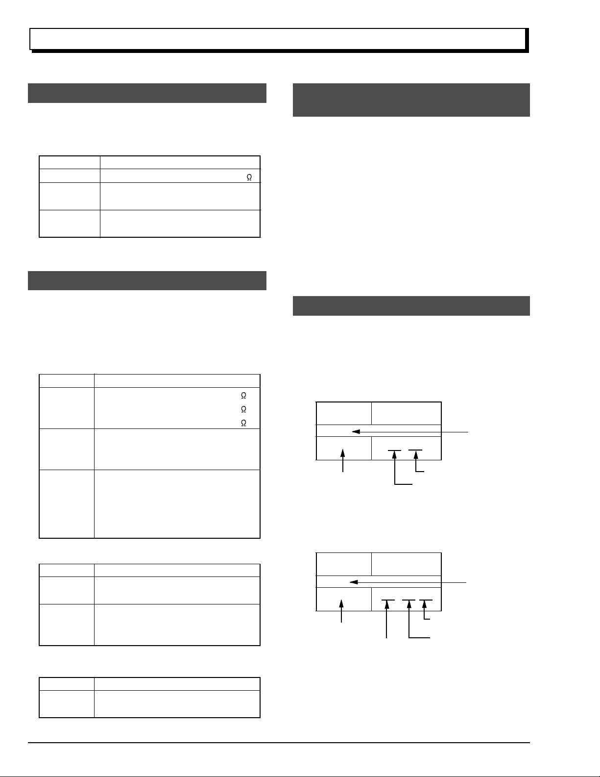
1. Value units used in parts list
Certain symbols are indicated below for value units of
resistors, capacitors and coils in parts list. When you read
them note the following regular indications:
Parts
Resistor
Capacitor
Coil
Indication in list Regular indication
...........................................
KOHM
................................................
UF
................................................
PF
................................................
UH
...............................................
MH
2. Values in schematic diagrams
The values, dielectric strength (power capacitance) and
tolerances of the resistors (excluding variable resistors)
and capacitors are indicated in the schematic diagrams
using abbreviations.
[Resistors]
Item
Value
Tolerance
Power
capacitance
Indication
No indication
...................................................
K
..................................................
M
No indication
(All tolerances other than ±5% are
indicated in schematic diagrams)
No indication
(1/16W for leadless resistors without
indication)
All capacitances other than the above
are indicated in schematic diagrams.
...................................
.............................
............................
±5%
1/8W
k
M
k
µF
pF
µH
mH
3. Identifications of sides A/B in
circuit board diagrams
1) Board having a pattern on one side and parts on both
sides.
Side A: Shows discrete parts, viewed from the pattern
side.
Side B: Shows leadless parts, viewed from the
pattern side.
2) Board having patterns on both sides and parts on
both sides.
Side A: Shows parts and patterns which can be seen
when the case is opened.
Side B: Shows parts and the pattern on the back of
side A.
4. Table for indexing locations of parts
This table shows locations of each part on circuit board
diagrams. The locations are indicated using the guide
scales on the external lines of diagrams.
1) One diagram indicated for each board
Symbol
No.
IC
IC1201
Circuit No.
2) Two diagrams indicated for each board
Parts
Location
Type of part
2 A
Zone "A" on board diagram
Zone "2" on board diagram
[Capacitors]
Item
Value
Dielectric
strength
[Coils]
Item
Value
CAUTION-2
Indication
No indication
...................................................
P
No indication
(All dielectric strengths other than 50V
are indicated in schematic diagrams)
Indication
....................................................
µ
..................................................
m
.................................
..............................
µF
pF
50V
µH
mH
Symbol
No.
IC
IC1201
Circuit No.
Parts
Location
A - 2 A
A: Shows side A
B: Shows side B
Type of
part
Zone "A" on board
diagram
Zone "2" on board
diagram

CONTENTS
CHAPTER 1 GENERAL INFORMATION
SPECIFICATIONS
COMPARISON OF FEATURES
COMPARISON OF MAIN CONTROL ICs
JIGS AND TAPES FOR SERVICE
HOW TO USE THE EXTENSION CABLE AND JIG..1-5
SERVICE POSITION
SERVICE MANUAL ABBREVIATION LIST
EXTRACT FROM THE INSTRUCTION MANUAL
Identifying Controls
Fertures
Charging the Battery
Items Selectable with Manu Displays
Setting the Date and Time
General Maintenance
.....................................................
................................
.................
............................
.................................................
...............
.....
..............................................
................................................................
............................................
..................
...................................
...........................................
1-1
1-2
1-3
1-4
1-5
1-6
1-8
1-8
1-9
1-10
1-11
1-11
1-12
CHAPTER 2 DISASSEMBLY
1. BEFORE STARTING DISASSEMBLY
1.1 Disassembly Procedure
2. CASES AND CIRCUIT BOARDS REMOVAL
2.1 Jack Cover, Front Cover Assembly,
Lens Cover,
2.2 PSW Circuit Board, Microphone Unit,
DC Light, Front Cover
2.3 LCD Case-U, LCD Block, Cassette Lid,
Top Cover
2.4 L-Case Assembly, R-Case Assembly
2.5 Electronic Viewfinder (EVF) Assembly,
Speaker, CON Circuit Board, Fulcrum,
L-Case
2.6 Camera Chassis Assembly [Lens Frame,
Lens, SE Circuit Board, CCD Sensor],
VCR Chassis Assembly, Jack Unit, Rear
Cover, Power Terminal Unit
2.7 VCA Circuit Board, Mechanism Frame,
UH Mechanism
2.8 Hand Strap, TW/PW Switch, R-Case
2.9 LCD Circuit Board, Back light,
LCD Module, LCD Case-B
2.10 EVF Case-R, EVF Case-L, Eye Piece
3. HOW TO OPERATE THE
MECHANISM MANUALLY
..................................................
....................................................
..........................................................
.............................................
...............................
..................................
...............................
.................
......
..........
.........................
...........
...........................
.........
2-1
2-1
2-2
2-2
2-2
2-3
2-4
2-5
2-6
2-7
2-7
2-8
2-8
2-9
CHAPTER 3 ELECTRIC CIRCUIT
ADJUSTMENT
1. CONNECTION FOR ADJUSTMENT
1.1 Before Starting Adjustment
2. CAMERA SECTION ADJUSTMENT
2.1 Test Equipment Necessary for
Adjustment
2.2 List of Charts for Camera Adjustment
2.3 Adjustment Conditions
...................................................
.................................
...................
..........................
....................
..........
3-1
3-1
3-2
3-2
3-2
3-2
2.4 Preset Positions of Switches and
Controls During Adjustment
2.5 Check After Replacing Major Components
in the Camera Section
2.6 Adjustment Procedure
2.6.1 Connections for Adjustment
2.6.2 How to Start the MAP
2.6.3 Initial Setting by Model
2.6.4 Digital Adjustment Procedure
(1) Auto Iris Control Adjustment
(2) White Balance Adjustment
(3) Chroma Gain Adjustment
2.6.5 Autofocus Adjustment Procedure
(1) Zoom Trace Adjustment
(2) AF Noise Level Adjustment
2.6.6 Stabilizer Adjustment Procedure
2.6.7 Spot Noise Adjustment
2.7 Color LCD Monitor Adjustment
2.7.1 Adjustment Procedure
(1) Flicker Adjustment
3. VCR SECTION ADJUSTMENT
3.1 Test Equipment and Alignment Tapes
Necessary for Adjustment
3.2 Adjustment Conditions
3.3 Preset Positions of Switches and
Controls During Adjustment
3.4 Check After Replacing Major Components
in the VCR Section
3.5 System Control/Servo Circuits
Adjustment
(1) Power Shut Off Level (ODC: Over
Discharge Control) Adjustment
(2) Head Switching Point Adjustment
4. ERROR MESSAGES
4.1 Digital Adjustment
4.2 Autofocus Adjustment
4.3 Stabilizer Adjustment
4.4 Spot Noise Adjustment
4.5 VCR Adjustment
5. TROUBLESHOOTING OF AUTOFOCUS
(1) No Zoom and Focus Operation
(2) No Focus Lens Operation
(3) No Zoom Operation
(4) No Autofocus Operation
(5) Subject is Greatly Out-of-Focus
When Zoomed
.......................................
...................................................
...........................................
........................................
...........................................
.............................................
.........................
.................................
.................................
..................
............................
..........................
.................
....................
......................
........................
...................
..........................
....................
...........................
.................................
...........................
............................
.................................
.........................
..................................
...................................
................................
....................
............................
.....................................
...............................
CHAPTER 4 EXPLODED VIEW
CABINET (1)
CABINET (2)
UH MECHANISM
ACCESSORIES
..............................................................
..............................................................
.......................................................
.........................................................
...............
.........
...........
.............
.........
...........
3-2
3-3
3-3
3-3
3-4
3-4
3-5
3-5
3-5
3-6
3-7
3-7
3-7
3-8
3-8
3-9
3-9
3-9
3-10
3-10
3-10
3-10
3-10
3-10
3-11
3-11
3-12
3-12
3-13
3-13
3-13
3-14
3-15
3-15
3-17
3-18
3-19
3-21
4-1
4-2
4-3
4-4
CONTENTS - 1

CHAPTER 5 REPLACEMENT
PARTS LIST
1. MECHANICAL PARTS LIST
2. ELECTRICAL PARTS LIST
CHAPTER 6
SCHEMATIC, CIRCUIT BOARD
................................
.................................
AND BLOCK DIAGRAMS/
MICROPROCESSOR PIN
FUNCTION TABLE
INTERNAL WIRING DIAGRAM
SENSOR/GYRO [SE]
CAMERA PROCESS [VCA]
SYSTEM CONTROL [VCA]
MECHA. STATE SWITCH/
MECHA. SENSOR
POWER SW [PSW]
SERVO [VCA]
AUDIO -MONAURAL- [VCA]
REGULATOR [VCA]
VIDEO PROCESS [VCA]
CHARGE [VCA]
CONTROL [CON]
LCD DRIVE [LCD]
...................................
....................................
......................................
...............................................
.....................................
............................................
.........................................
........................................
.................................
Schematic /Circuit
.........................
..........................
........................
..............................
5-1
5-2
6-1
Board
6-3 / 6-29,31
6-5 / 6-33,35
6-7 / 6-33,35
6-9 / ----6-10 / 6-29,31
6-11 / 6-33,35
6-13 / 6-33,35
6-15 / 6-33,35
6-21 / 6-33,35
6-24 / 6-33,35
6-25 / 6-29,31
6-27 / 6-37
CHAPTER 7 APPENDIX
1. SELF-DIAGNOSTIC FUNCTION
1.1 Overview
1.2 Details of Display/
Detection and Applications
1.3 Setting Procedure and
Details of Diagnosis
1.3.1 Occasional Defect Self-Diagnostic
1.3.2 Mechanical Block Self-Diagnostic
2. DEMONSTRATION (DEMO) MODE
2.1 Setting the Demo Mode
2.2 Exiting the Demo Mode
2.3 Contents of Demonstration
......................................................
Function (Mode A)
Function (Mode B)
.........................
..........................
.....................................
.................................
.................................
...............................
................................
..........................
CHAPTER 8 AC ADAPTER
VM-ACE5A
................................................................
....................
7-1
7-1
7-2
7-3
7-3
7-4
7-6
7-6
7-6
7-6
8-1
WAVEFORM
SENSOR/GYRO
SYSTEM CONTROL
SERVO
VIDEO PROCESS
BLOCK DIAGRAMS
1. OVERALL BLOCK DIAGRAM
2. MAIN CONTROL BLOCK DIAGRAM
3. SERVO BLOCK DIAGRAM
4. CAMERA & VIDEO PROCESS
5. AUDIO -MONAURAL- BLOCK DIAGRAM
6. POWER BLOCK DIAGRAM
MICROPROCESSOR PIN FUNCTION TABLE
1. Digital Microprocessor (IC1104: D-µP)
2. System Control Microprocessor
.................................................................
BLOCK DIAGRAM
(IC0901: S-µP)
..................................................
............................................
...............................................
.......................
...........................
........................................
..........................
..............................................
............
....
.........
6-3
6-9
6-11
6-19
6-41
6-43
6-45
6-47
6-49
6-51
6-53
6-56
CONTENTS - 2

CHAPTER 1 GENERAL INFORMATION
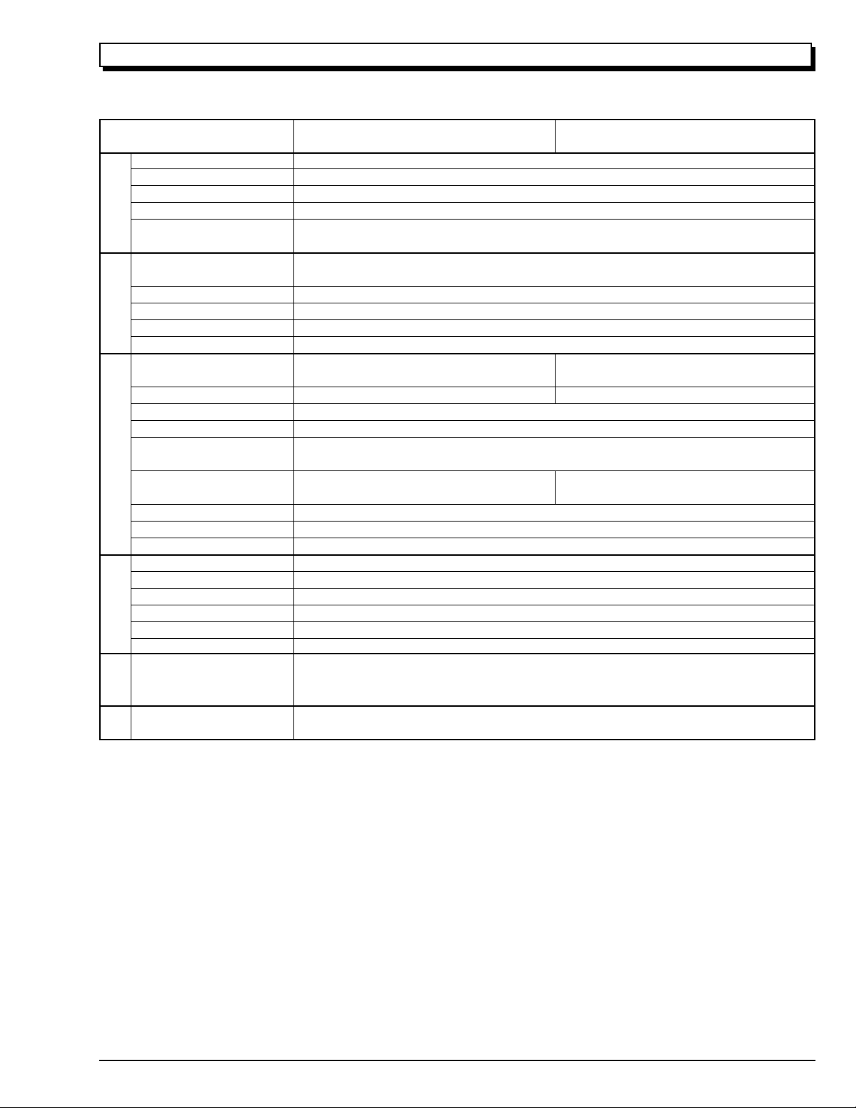
SPECIFICATIONS
General Specifications
Power requirements 7.2 V DC
Power consumption VM-H675LA:
3.5 W (when recording/LCD monitor OFF)
4.0 W (when recording/LCD monitor ON)
VM-E575LA:
3.4 W (when recording/LCD monitor OFF)
3.8 W (when recording/LCD monitor ON)
VM-E573LA:
3.4 W (when recording/LCD monitor OFF)
3.8 W (when recording/LCD monitor ON)
Dimensions 4-3/8" W × 4-3/8" H × 7-7/8" D
(111.5 mm × 111.5 mm × 200 mm)
Weight 1.84 Ids (approx. 836 g) without battery pack and cassette
Operating temperature 32 °F to 104 °F (0 °C to 40 °C)
Storage temperature -4 °F to 140 °F (-20 °C to 60 °C)
Video Recorder Specifications
Format 8 mm
Record/playback Two video record/playback heads
Video signal EIA standard NTSC color
Tape speed 14.3 mm/s
Video output 1.0 Vp-p, 75 ohm
Audio output -7.8 dBs (316 mVrms)
Fast forward/rewind time Less than 8 minutes with P6-120 cassette
Camera Specifications
Scanning 525 lines/60 fields/30 frames
Required minimum illumination VM-H675LA: 0.5 lx
VM-E575LA: 0.3 lx
VM-E573LA: 0.3 lx
Pickup device 1/4" C.C.D.
Lens F1.6 to 3.8 (4 to 88 mm) 22:1 power zoom lens with auto focus and
auto iris functions
Lens diameter 46 mm
1 - 1
COMPARISON OF FEATURES
Note: Destinations normally added at the end of model names, (K), etc. are omitted in this table.
ITEM
Power Requirements
Power Consumption
(when recording/LCD
monitor ON)
Dimensions (W × H × D )
GENERAL
Weight
Format
Record/Playback System
Video Signal
Tape Speed
VIDEO
F.F/Rew Time
Head Weel
Basic Chassis Type
Scanning
Required Minimum
Illumination
Camera Device
Lens Diameter
CAMERA
Zoom Ratio
Aperture
Zoom Speed
Electronic Viewfinder
(EVF)
Electrical Zoom Function
INST. ZOOM Function
Autofocus System
Program AE
(Shutter Speed)
Selective Program AE
AV Input Function
S-Connector Output
AV Dubbing
Audio System &
Microphone
FEATURES
Multi Playback
(PAL 60 Conversion)
Digital Effect & Fade
Date Search
Tape Analyzer ATRS
TAPE+ Function
Electronic Image Stabilizer
(EIS)
LCD Display
Internal DC Light
Internal Battery Charge
AC Adapter/Charger
Battery Pack
ACCE-
SSORY
Remote Controller
VM-H675LA/E575LA/E573LA
7.2 V DC
4.0 W [VM-H675LA]
3.8 W [VM-E575LA/E573LA]
111.5 mm × 111.5 mm × 200 mm
Approx. 836 g
8 mm (Hi-8) [VM-H675LA]
8 mm [VM-E575LA/E573LA]
Two video record/playback heads
EIA Standard NTSC color
SP: 14.3 mm/s
Less than 8 minutes with P6-120 cassette
40 mm
UH
525 lines/60 fields/30 frame
0.5 lx [VM-H675LA]
0.3 lx [VM-E575LA/E573LA]
1/4 inch C.C.D
46 mm
22 : 1 (4.0 - 88.0 mm)
F1.6 - 3.8
Adjustable speed
CRT (Black & White)
Yes [× 500 (22 × 22)]
No
Video AF System
Yes
(Program AE only)
Yes [VM-H675LA]
(AUTO, SPORTS, PORTRAIT,
SPOTLIGHT, GAIN UP)
No [VM-E575LA/E573LA]
No
Yes [VM-H675LA]
No [VM-E575LA/E573LA]
Yes (Using the remote controller)
Monaural
Yes (Selective)
Yse
Yes
Yes [VM-H675LA]
No [VM-E575LA/E573LA]
Yes [VM-H675LA]
No [VM-E575LA/E573LA]
Yes (Picture element system)
Yes (2.5 inch)
Yes [VM-H675LA/E575LA]
No [VM-E573LA]
Yes
VM-ACE5A [Except for (K)]
VM-ACE5E(K) [For (K)]
VM-BPL13
VM-RME611A
VM-H665LA/E563LA
4.0 W [VM-H665LA]
3.8 W [VM-E563LA]
111.5 mm × 111.5 mm × 202 mm
8 mm (Hi-8) [VM-H665LA]
8 mm [VM-E563LA]
0.5 lx [VM-H665LA]
0.3 lx [VM-E563LA]
Yes [VM-H665LA]
(AUTO, SPORTS, PORTRAIT,
SPOTLIGHT, GAIN UP)
No [VM-E563LA]
Yes [VM-H665LA]
No [VM-E563LA]
Monaural
Yes [VM-H665LA]
No [VM-E563LA]
Yes [VM-H665LA]
No [VM-E563LA]
Yes [VM-H665LA]
No [VM-H563LA]
1 - 2
COMPARISON OF MAIN CONTROL ICs
Note: Destinations normally added at the end of model names, (K), etc. are omitted in this table.
ITEM
CCD Sensor
V-Move (Vertical Gyro)
H-Move (Horizontal Gyro)
Gyro Amp
GYRO
Sensor Drive (Drive Pulse
SENSOR &
Generator)
Video DSP
(Digital Process)
CDS/AGC & A/D Conv.
Video Head Switch
VIDEO
Video Amp
PROCESS
RGB Amp
Digital µP (D-µP)
EEPROM
D/A Conv.
F Det./Iris Drive
Zoom Motor/Focus Motor
Driver
System Control µP (S-µP)
SYSTEM CONTROL
Back-up Det.
CAMERA CONTROL &
Character Gen.
IR Receiver
Cylinder Motor Drive
Capstan Motor Drive
Loading Motor Drive
PWM
POWER
SERVO &
5V Reg.
CHG Current Cont.
Audio Process
VM-H675LA/E575LA/E573LA
ICX206AK (IC1001)
ENC-03JA-07 (IC1401)
ENC-03JB-07 (IC1402)
NJU7018M (IC1403)
µPD16510GR (IC0203)
MB87L1551PMT2 (IC0201)
HD49323AF (IC0202)
HA118189MP (IC0101)
µPC5020GS129 (IC0301)
µPC5020GR-125-8JG (IC0350)
HD6432237M10TE (IC1104)
X25170S8I-2.5T3 (IC1105)
MB88347PFV (IC1111)
µPC5023GS-147-GJG (IC1201)
µPD16833AG3 (IC1301)
CXP87360-133R (IC0901)
NJU7285BV (IC0902)
µPD6461GS-947-E1 (IC0904)
GP1U101X (IC0701)
LB1950V-TLR (IC0631)
LB1991V-TLR (IC0651)
BA6417F (IC0671)
BA9736KV (IC0551)
PQ20WZ51 (IC0553)
MM6564XFBE (IC0001)
LA7458W (IC0401)
VM-H665LA/E563LA
HD6432237M08TE
HD6432237M10TE
AT25160N (IC1105)
CXP87360-132R
CXP87360-133R
(IC1104)
(IC0901)
AUDIOLCD
LCD SWR.
TL5001CD (IC5501)
1 - 3
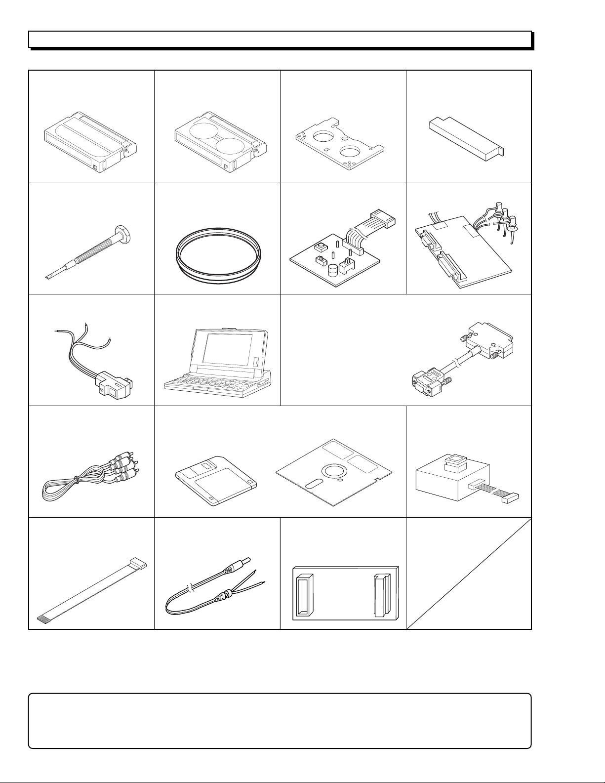
JIGS AND TAPES FOR SERVICE
1. Alignment Tape 2. Cassette Torque Meter 3. Master Plane 4. Reel Disk Height Jig
20HSC-2: No. 7099231 SRK-8T-132: No. 7099235 No.7099237 No. 7099238
SRK-8T-112: No. 7099385
5. Special Driver 6. C12 Light Balance 7. ATF-R Jig
No. 7099239 Filter No. 7099461 No. 7099448
No. 7099369
9. DSP AV Output Jig 10. Presonal Computer 11.Personal Computer Cable
No. 7099456 [Goods on the market] RS-232C (9-pin or 25-pin)
Straight Type Cable
[Goods on the market]
12. AVOutput Cable
[Accessory] 3.5 inch: No. TP12115 Cable
(*3)
13. Adjustment Floppy Disk
5 inch: No. TP12116 No. TS15411
[New Jig]
(*1,*2)
8. DSP-R jig
14. 8 - 20 Pin Extention
15. 4-Pin Extension Cable 16.ODC DC CORD 17. 80-Pin Extention Board
No.7069203 No. TE13171 No. JP25461
Caution for jigs
*1
. Always set SW3 on the ATF-R jig to ON.
*2
. The ATF jig (No.7099386) can also be used in place of ATF-R jig to adjust this model.
*3
. Either the monaural or stereo AV output cable can be used.
1 - 4
HOW TO USE THE EXTENSION CABLE AND JIG
Name of Jig Parts No. How to Use
8 - 20 Pin Extention TS15411 Used for electrical adjustment. Connected between PG905 on the VCA circuit board
Cable and DSP Output Jig (20 pins). Refer to Fig. 1-1 on the page 3-1.
4-Pin Extension Cable 7069203 Installed between the VCA circuit board and mode switch (mechanism state switch).
ODC DC Cord TE13171 Power supply cable for power shut off level (ODC) adjustment. Refer to Fig. 1-1 on the
page 3-1.
Positive: Black
Negative: Black & White
80-Pin Extension Board JP25461 Installed between the VCA circuit board and CON circuit board.
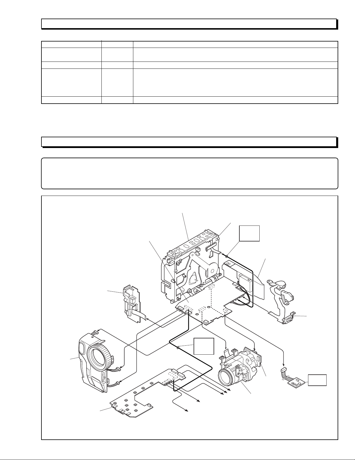
SERVICE POSITION
NOTE
1. If the front cover assembly is connected to the VCA circuit board, the provided remote control can be used to operate
the camera/recorder without connecting the CON circuit board.
2. The VCR block can be operated with the camera chassis assembly removed.
FRONT
COVER
ASSEMBLY
JACK
UNIT
VCA
CIRCUIT
BOARD
UH MECHANISM
MECHANISM
FRAME
4-PIN
EXT.
CABLE
REAR
UNIT
TW/PW
SWITCH
80-PIN
EXT.
BOARD
CON
CIRCUIT
BOARD
To SPEAKER
To EVF
Fig.1-1 Service Position
To LCD
SE
CIRCUIT
BOARD
CAMERA
CHASSIS
ASSEMBLY
ATF-R
JIG
1 - 5
SERVICE MANUAL ABBREVIATION LIST
A
A (A-) Analog
ACC Automatic Color Control
A/D Analog-to-Digital Converter
ADD Adder
ADP. Adapter (AC Adapter)
ADRS Address
A.DUB Audio Dubbing
AF Automatic focus (Autofocus)
AFC Automatic Frequency Control
AGC Automatic Gain Control
AGC KILLER AGC Killer Voltage
AI Automatic Intelligence
AIC Automatic Iris Control
ALC Automatic Level Conrol
AMP Amplifier
APC Automatic Phase Control
ASBL Assemle (Phase Matching)
ATRS Auto Tape Recording System
AUD. Audio
AUX Auxiliary
B
B (BLU) Color Signal Blue
BATT. Battery
BF Burst Flag
BG Burst Gate or Back Ground
BGP Burst Gate Pulse
BLC Backlight Compensation
BLK Blanking
BPF Bandpass Filter
BUF. Buffer Amplifier
B-YL Color Difference Signal B-YL
C
C (CHROMA) Chrominance Signal
CAM Camera
CAPST. Capstan
CARRI. Carrier
CATV Cable TV
C.BLK Composite Blanking
CCD Charge Coupled Device
CDS Correlated Double Sampling
C.FG (CFG) Capstan Frequency Generater
C.FREE RUN Capstan Free Run
CG Character Generator
CH (Ch or ch) Channel
CHARA. Character
CHD Camera Horizontal Drive Pulse
C.MEMORY Counter Memory
CNR Chroma Noise Reducer
COM. Common
COMPA. Comparator
COMPE. Compensator
COMP-EXP Compressor-Expander
COMPO Composite
CONT. Control
CONV. Converter
COUNT. Counter
CP CP
C.PAUSE Camp Pulse
C/R Capacitor/Resistor
C.RESET Countor Reset or Camera Reset
C.REVERSE Count Reverse
CS Communication Signal
C
CST Cassette
C.SYNC Composite Synchronizing Signal
CTL Control Track Pulse (Control)
CYL Cylinder
D
D (D-) Digital
DA Double Azimuth
D/A Digital to Analog Converter
D-D Direct Drive
DEEMPHA. Deephasis
DEF Deflefction
DEMOD. Demodulator
DET Detector
DIFF. AMP Differential Amplifier
Digital 8 (D8) Digital 8 mm
DISP. Display
DL Delay Line
DO Dropout
DOC Dropout Compensator
DSP Digital Signal Processor
DUB Dubbing
DV Digital Video
DVD Digital Versatile Disc
D-VHS Digital VHS
D/W Dark/White
D.ZOOM (DZ) Digital Zoom
E
EAROM Electrically Alterable Read Only
Memory
E-E Electronic-to-Electronic
EEPROM Electrical Erasable Proframmed
Memory
EIS (E.I.S.) Electronic Image Stabilizer
EMPHA. Emphasis (EMPH)
EQ Equalizer
ESS End Sensor Supply (Supply End Sensor)
EST End Sensor Take-up
(Take-up End Sensor)
EVF Electronic Viewfinder
EXT. External
E.ZOOM Electrolical Zoom
F
F.ADV Frame Advance
FB Feed back
FE Full Erase
FF (F/F) Flip Flop
F.FWD Fast Forward
FG Frequency Generator
FM Frequency Modulation
FREQ. Frequency
fsc Sub Carrier Frequency
F/V Frequency-to-Voltage Converter
FWD Forward
G
G (GRN) Color Signal Green
GEN. Generator
GND Ground
H
H (HORIZ.) Horizontal
HB Hi-Band
HBF Horizontal Burst Flag
HD Horizontal Drive
1 - 6
H
Hi-Fi High Fidelity
HPF High-pass Filter
HSW Head Switch
I
IF Intermediate Frequency or Interface
INDI. Indicator
INST. Instant
INT. Internal
INV. Inverter
I/O In/Out (Input/Output)
IR Infrared Rays
L
LB Low-Band
LCD Liquid Crystal Dissplay
LIN. Linear
LM Loading Motor
LNC Line Noise Canceller
LOG Logarithm
LP Long Play
LPF Low-pass Filter
L/R Left/Right
LUMA Luminance
M
MAN Manual
M.BRAKE Main Brake
M.CUT Monitor Cut
MEM. Memory
MIC Microphone
MIX Mixer
MMV Monostable Multivibator
MOD. Modulator
MPEG Noving Picture coding Experts Group
M.STATE Mechanism State
M.STOP Memory Stop
N
NEG Negative
NFB Negative Feed Back
NOR. (NORM) Normal
NR Noise Reduction
O
OB Optial Black
OSC Oscillator
OSD On-Screen Display
P
PB (PLAY) Playback
PCM Pulse Code Modulation
PG Pulse Generator
PLL Phase Locked Loop
POS. Positive
PROG. Program
PROT. Protector
PWM Pulse Width Modulation
R
R (RED) Color Signal Red
RAM Random Access Memory
REC Record
RECT. Rectifier
REF. Reference
REG. Regulator
REV Review
REW Rewind
RF Radio Frequency
R
ROM Read Only Memory
RSS Reel Sensor Supply
(Supply Reel Sensor)
RST Reel Sensor Take-up
(Take-up Reel Sensor)
R-YL Color Difference Signal R-YL
S
SAW Sawtooth Signal
SC1 (0°) 3.58MHz Subcarrier Signal 1
(0-degree Phase Shifted)
SC2 (90°) 3.58MHz Subcarrier Signal 2
(90-degree Phase Shifted)
SEPA. (SEP) Separator
S/H Samle and Hold
SP Standard Play or Speaker
S.REEL Supply Reel Sensor
SRCH Search
SRV Servo
STABI. Stabilizer
S.TRACK Slow Tracking
STBY Standby Mode
S-VHS Super VHS
SW Switch
SW30Hz 30Hz Head Switching Pulse
(15 or 25Hz) (15 or 25Hz Head Switching Pulse)
SYNC Synchronizing signal
SYS.CON System Control
T
T (TELE) Telephoto Angle
TAPE + Recording Hi-8 Quality Image on Normal
Tape
TBC Time Base Corrector
T.BRAKE Take-up Brake
TP Test Point
T.REEL Take-up Reel Sensor
TRS Transfer
V
V (VERT.) Vertical
V.AGC AGC Voltage
VCO Voltage Controlled Oscillator
VCXO Voltage Controlled Crystal Oscillator
VD Vertical Drive
V.DUB Video Dubbing
VHS Video Home System
VOL. Volume
VP Voltage Pulse
W
W (WIDE) Wide Angle
WHD Wide Horizontal Drive
WHT Color Sifnal White
WHT BAL. White Balance
Y
Y Luminance Signal
Y/C Luminance/Chrominance
YEL (Ye) Color Signal Yellow
YL Luminance Signal (Low Component)
1 - 7
1 - 8
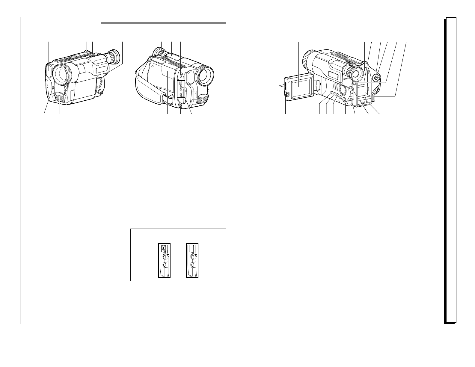
Identifying Controls
1
2 3 4 5 11 12 136
9 10 14 15 16 177
8
27
EXTRACT FROM THE INSTRUCTION MANUAL
19 20 21 23 24 25 262218
32 343328 29 30 31
1. Built-in DC Light (p56) (for VMH675LA/VM-E575LA)
2. Lens Door (p28)
The lens door will open automatically when the
camcorder is set to the camera (CAM) mode.
3. Power Zoom Control (p31)
4. Cassette Eject Switch (p22)
5. Shoulder Strap Slot (p16)
6. Charge Indicator (p17)
7. Record Indicator (p28)
8. Infrared Receiver (p14)
9. Microphone
10. CAM/OFF/VIDEO Power Switch
(p28)
CAM: Set to this position to record.
VIDEO: Set to this position to play back a tape.
11. Diopter Control (p16)
To adjust the viewfinder eyepiece to suit your eyesight.
12. Electronic Viewfinder (p16)
13. DC Light Switch (p56)
(for VM-H675LA/VM-E575LA)
To switch the DC light between ON, OFF and
AUTO.
14. Hand Strap (p16)
15. Cassette Holder (p22)
Insert cassette here.
16. Microphone Jack
(for VM-H675LA)
Connect external microphone (not supplied) here.
17. Audio/Video Output Jacks
(Behind the jac k cover) (p50)
Connect the provided AV cable from this jack to
the AV input jack of your TV or VCR. The jacks on
camcorder differ for each model as follows:
VM-H675LA has S-VIDEO jack and monaural
audio output jack.
VM-E575LA/VM-E573LA has monaural audio
output jack.
VM-H675LA VM-E575LA/
VM-E573LA
18. LCD Brightness Controls (p14)
19. 2.5-inch LCD Monitor (p14)
20. Speaker (p32)
21. Power Supply Attachment
Section (p17)
22. Clock Battery Compartment
(p13)
23. Sub Power Switch
STANDBY: Pressing the Start/Stop button will
start recording.
LOCK: The camcorder will not enter the
record mode even if the Start/Stop
button is pressed.
24. Start/Stop Button (p28, 33)
This works as a recording start/stop button in the
CAM mode and as a playback pause button in the
VIDEO mode.
25. BATT. EJECT Lever (p18)
Sliding, and then holding, this switch, remove the
battery from the camcorder.
26. Shoulder Strap Slot (p16)
27. LCD Monitor OPEN Button (p14)
To open the LCD monitor.
28. DATE Button (p26)
To set the date or display it.
29. TITLE Button (p46)
To select or create a title, or display one.
30. EFFECT Button (p37)
To record digitally processed image or play back
picture with digital effect added.
31. FOCUS/VOL Control Buttons
(p32, 36)
CAM mode: To switch between auto focus and
manual focus, or to control focus
while in manual focus mode.
VIDEO mode: To control playback volume.
32. BLC (Backlight Compensation)
Button (p43)
When recording a subject in bright light, hold this
button down to compensate for lighting on tape.
33. MENU Button (p23)
To display the menu.
34. DC IN Jack (p21)
Use this jack to power the camcorder from the AC
adapter or from battery in your vehicle.
[For VM-H675LA/E575LA/E573LA]
E10 HITACHI
E11VM-H675LA/VM-E575LA/VM-E573LA
E7VM-H675LA/VM-E575LA/VM-E573LA
Features
Easy to use
Color liquid crystal display (LCD) monitor with
speaker
Tape analyzer ATRS (for VM-H675LA)
TAPE+ function (for VM-H675LA)
Active screen
Perfect power (Lithium-ion battery)
Built-in DC light (for VM-H675LA/VME575LA)
X22 optical zoom ratio
X100 digital zoom ratio (switchable to X500)
Digital effects
Stable pix (Electronic Image Stabilization (EIS))
Fade in/fade out
Recorded date search
Video effects
Multi playback (PAL60 conversion)
With this camcorder you can view the picture being recorded or the playback picture whether on the
LCD monitor or in the viewfinder. Opening or closing the LCD monitor switches the picture to
appear on the LCD monitor or in the viewfinder. The following text describes the operation assuming that the viewfinder is used as a major monitor device.
Types of differences
System
Built-in DC light
Yes Yes
VM-H675LA VM-E575LANoVM-E573LA
This instruction manual contains illustrations of VM-H675LA camcorder and displays. Some displays
do not appear, depending on the model.
Tape+
Yes No
Program AE
Auto/Mode select Auto
No
Auto
Microphone Jack
Yes No
No
39
40
41
DISPLAY
COUNTER
RESET
A/V DUB
TITLE
ON/OFF
START
/STOP
PAUSE
PLAY F.FWDREW
STOP
ZOOM
T
W
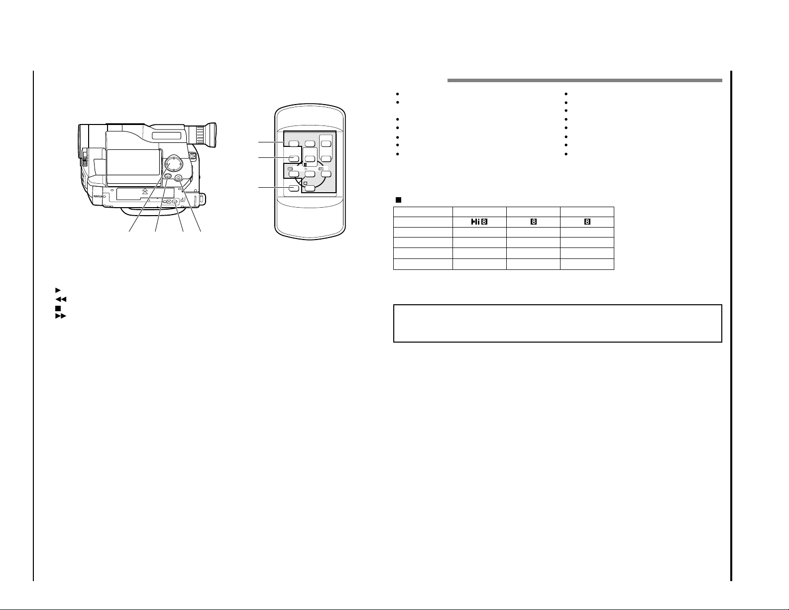
35. Tape Transport and Menu
Tape Transport Buttons:
Menu Setting Buttons:
To select menu items and set details.
36. FADE Button (p40)
To select the desired fade mode.
37. Tripod Mounting Threaded
Setting Buttons (p23, 32)
PLAY: To play back tape.
REW: To rewind tape.
STOP: To stop tape.
FWD: To fast forward tape.
35 36 37 38
REMOTE CONTROL
39. Recorder Remote Control
Same functions as the corresponding buttons on
the camcorder.
40. COUNTER RESET Button (only on
the remote control) (p45)
To reset the time counter to 0:00:00.
41. A/V DUB Button (only on the
remote control) (p53)
To dub audio and video.
Socket
38. PROGRAM AE Button (p42)
(for VM-H675LA)
To change the exposure.
1 - 9
E12 HITACHI
1 - 10
EVF
LCD
EVF
LCD
VM-H675LA
EVF
LCD
VM-H675LA
E18 HITACHI
Notes on the Battery
It is recommended that the battery always be left
in the discharged state when not in use, and
charged before you use it.
Avoid storing a fully charged battery, and do not
store it in a place where the temperature is high:
this will damage the battery.
Do not operate the battery at temperature below
14 F (– 10 C) or above 113 F (45 C). At extremely
low temperatures operation time decreases, while
at high temperature the battery may be damaged.
Do not attach a hot battery to the camcorder.
Allow it to cool.
THERE ARE NO USER-SERVICEABLE PARTS
INSIDE THE BATTERY
OR AC ADAPTOR.
THROWING THE BATTERY INTO FIRE
OR EXPOSING IT TO EXCESSIVE HEAT
(ABOVE 140 F [60 C])
MAY CAUSE INJURY.
SHORTING THE BATTERY’S TERMINAL
INCREASES RISK OF FIRE OR
ELECTRICAL SHOCK.
Removing the Battery Pack
Slide the BATT. EJECT lever in the direction of the
arrow and hold it; then slide the battery to the
upper side and remove.
Reference of Charged Level
You can know the approximate charge level of battery by observing how the BATT. CHARGE indicator of camcorder flashes or lights:
Charge level
BATT. CHARGE indicator
0-50% charge
50-75% charge
More than
75% charge
Full charge
Flashes once at approx. onesecond intervals.
Flashes twice at approx. onesecond intervals.
Flashes three times at approx.
one-second intervals.
Steady light
BATT. EJECT Lever
Charging Time
Battery
Charging
VM-
BPL13
Full charge
75% charge3h1h 50 min
VM-
BPL30
5h 30 min
3h 40 min
VM-
BPL60
9h 50 min
7h
Typical Recording
EVF: when using the viewfinder
LCD: when using the LCD monitor
Operating Time
The camcorder operating time depends on how
often you turn power on/off and use start/stop
and zoom.
Continuous Recording
EVF: when using the viewfinder
LCD: when using the LCD monitor
Battery
VM-BPL13 VM-BPL30 VM-BPL60
EVF
LCD
2h 45 min
2h 20 min
6h 5 min
5h 15 min
12h 20 min
10h 40 min
2h 50 min
2h 25 min
6h 15 min
5h 30 min
12h 40 min
11h 10 min
VM-E575LA
2h 50 min
2h 25 min
6h 15 min
5h 30 min
12h 40 min
11h 10 min
VM-E573LA
Battery
VM-BPL13 VM-BPL30 VM-BPL60
EVF
LCD
1h 40 min
1h 25 min
3h 35 min
3h 5 min
7h 20 min
6h 20 min
1h 45 min
1h 30 min
3h 45 min
3h 15 min
7h 35 min
6h 40 min
VM-E573LA
EVF
LCD
1h 45 min
1h 30 min
3h 45 min
3h 15 min
7h 35 min
6h 40 min
VM-H575LA
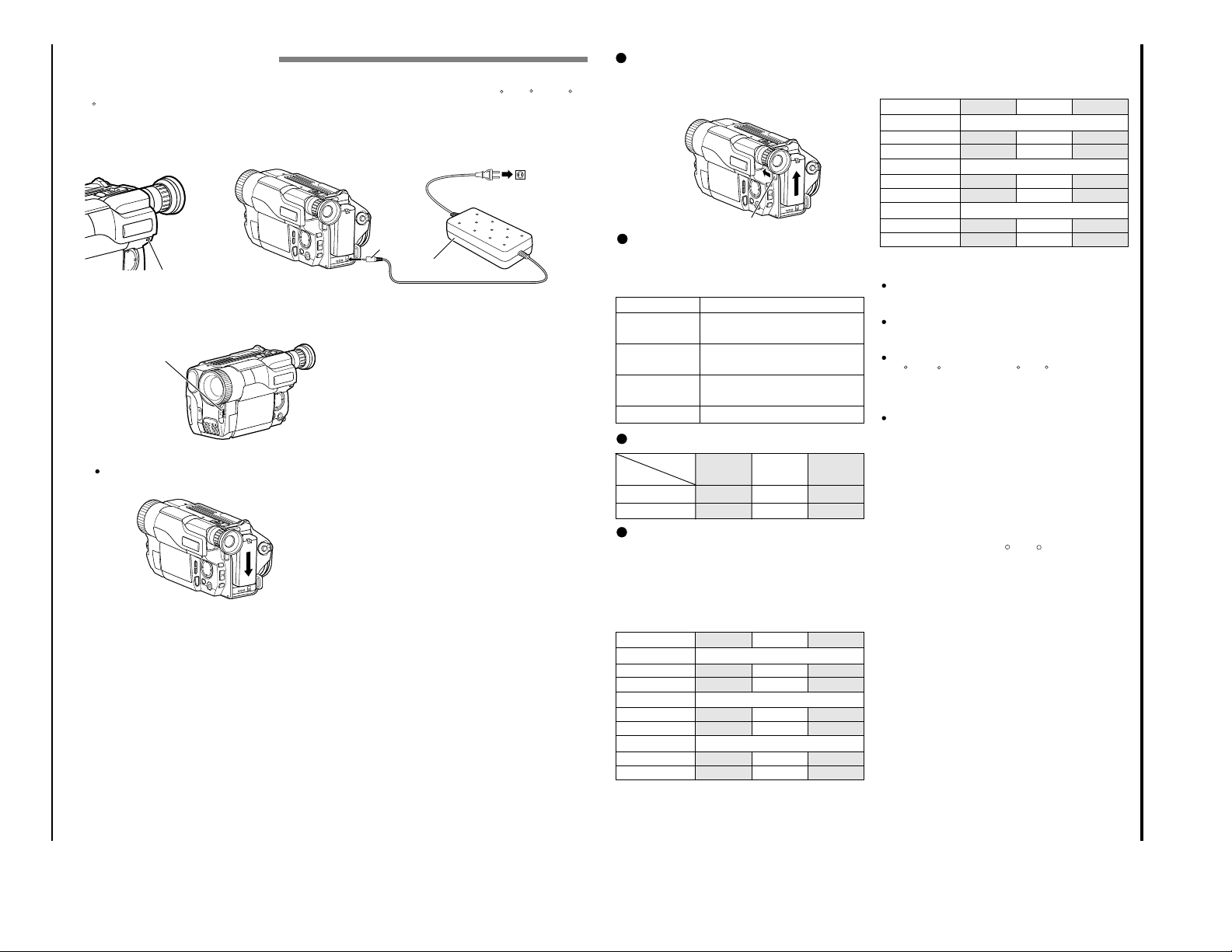
Charg ing the Battery
The first step is to set the battery for charging. To charge the battery, attach it to the camcorder, and
connect the VM-ACE5A AC adaptor. Charge the battery at a temperature range of 50 F (10 C) – 86 F
(30 C) to prevent damage to the battery.
Note: This camcorder operates with a lithium ion battery such as VM-BPL13/VM-BPL30/VM-BPL60.
Note: We cannot be responsible for any malfunctions of the camcorder which occur when you use bat-
tery packs other than those specified.
BATT. CHARGE Indicator
Charge the battery on a flat surface this is free of
vibration.
Make sure the CAM/OFF/VIDEO switch is set
1
to OFF position.
CAM/OFF/VIDEO Switch
Attach the battery pack to the camcorder.
2
Place the battery on the guide platform and
slide it down so that it fits into the camcorder.
Note: Always attach a battery only by the procedure described here. Attaching a battery
forcibly could damage it.
Plug the AC adaptor power cord into an AC
3
outlet.
Make sure that the wide blade fits into the wide
slot. If it doesn’t fit, try reversing it. If the
blades still do not fit fully into the outlet, either
contact an electrician to replace your obsolete
outlet, or use a polarized cord or outlet accessory.
Connect the AC adaptor DC plug to the DC IN
4
jack of the camcorder.
Charging will start within five seconds. During
charging, the BATT. CHARGE indicator of the
camcorder will flash or light to give you a refe -
To DC IN Jack
rence of the charged level.
Note: If the BATT. CHARGE indicator flashes
once every two seconds, the battery could be
defective.
Note: The BATT. CHARGE indicator will not light
at all when the AC adaptor is defective.
Note: You can use the battery before it is com pletely charged.
Note: When charging is complete, the BATT.
CHARGE indicator on the camcorder will light.
IF the fully charged battery is removed and
then reattached, the camcorder will again
enter the charge mode, and the BATT.
CHARGE indicator will flash. It will take a few
minutes for the camcorder to enter the charge
complete status.
Note: Charging at low temperatures will
decrease charge capacity.
After charging is complete, disconnect the AC
5
adaptor DC plug from the camcorder.
Disconnect the AC plug from the AC outlet.
6
Detach the battery from the camcorder.
7
Note: Always remove the battery from the
camcorder after use.
Note: Charging will not be performed when
the CAM/OFF/VIDEO switch of the camcorder
is set to CAM or VIDEO. However, if recording
pause continues for more than 5 minutes in the
CAM mode, the camcorder will automatically
turn off, after which charging will start. If the
sub-power switch is set to LOCK, charging will
be performed even when the CAM/OFF/VIDEO
switch is set to CAM.
Note: If the DC plug is disconnected when the
battery is attached and the CAM/OFF/VIDEO
switch is set to CAM or VIDEO, the camcorder
will turn off once, but then automatically turn
on again. Note that the battery will discharge
if the camcorder is left as is.
DC Plug
AC Adaptor
To AC Outlet
E17VM-H675LA/VM-E575LA/VM-E573LA
Items Selectable with Menu Displays
E26 HITACHI
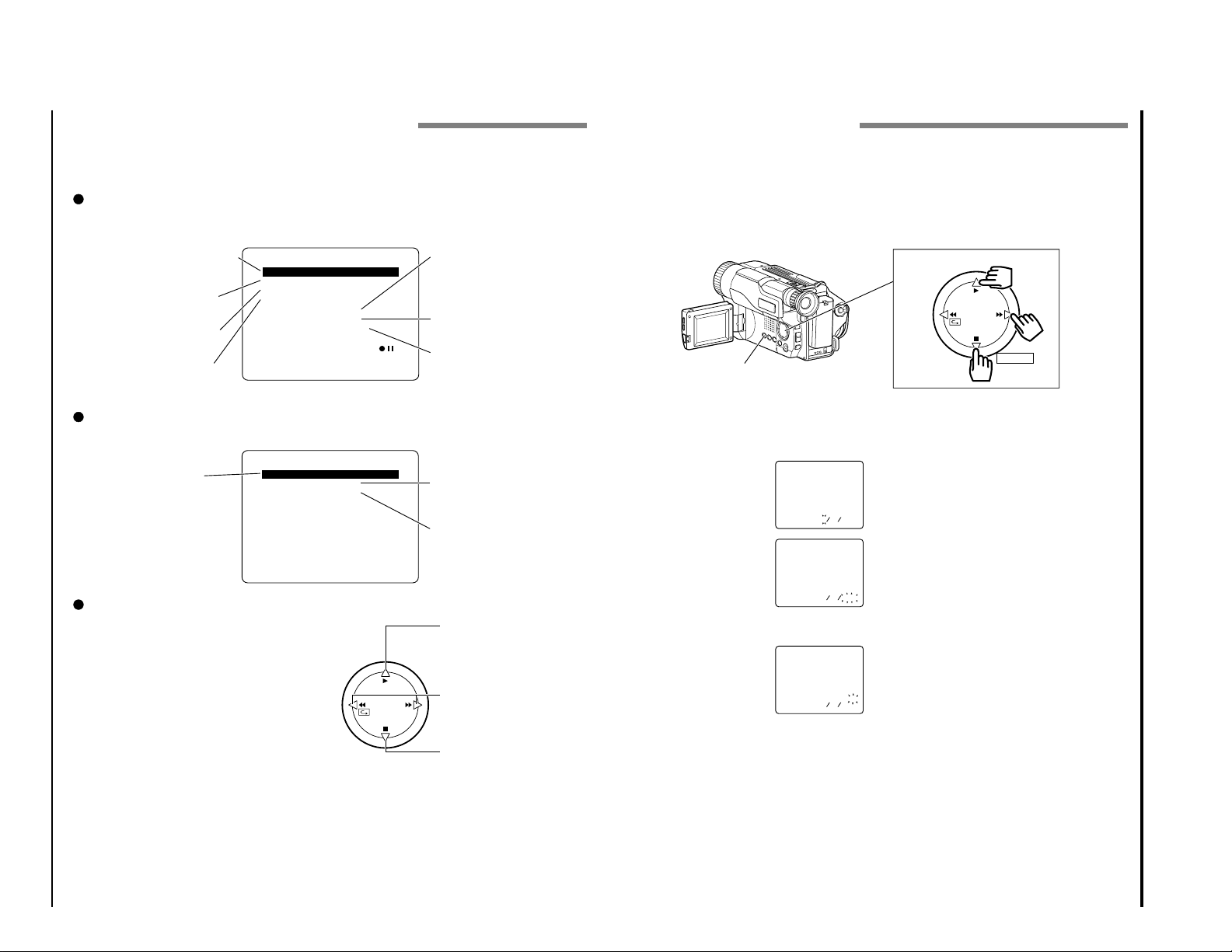
Setting the Date and Time
Take the time to set the date and time now. The date and time can be recorded on your tapes to act
as a handy reference when viewing them later. Use the following procedure to set up the display for
the current date and time.
Note: Be sure to insert the clock battery before setting the date and time. Although the date and time
can be set without the clock battery inserted, they will disappear when the battery providing power to
the camcorder is removed.
1
Load the battery. (“Camcorder Power Sources”,
p20.)
2
Press the small button on the CAM/OFF/
VIDEO switch as you slide it to CAM.
3
Open the LCD monitor, and
then press the DATE button.
The date and time should
appear in the lower right
with the “1” flashing.
4
Pressing the PLAY button
gives you higher numbers
while the STOP button gives
you lower numbers. Select
the right month and press FF
button. Use the PLAY, STOP
and FF buttons to select the proper day, year,
hour, minute, and AM or
PM.
5
After setting the AM/PM,
press the DATE button. The
display changes and the
internal clock starts.
Note: After the date and
time are set, the camcorder enters the date
recording mode. See “Date Recording” on
page 35.
Correcting the Date and Time
1
Hold down the DATE button for at least 3 seconds: The flashing cursor will appear at the
month.
2
Move to where you need to make the correction
with the FF button and use the PLAY and STOP
to correct.
3
Press the DATE button to set the corrected date
and time.
DATE Button
Date and Time Select Button
PLAY
STOP
REW FF
SELECT
000211
00:2
1AM
5111
00:21
A
M
0002
0102511
30:6
A
M
1
Make sure that the current time is displayed correctly before you start filming.
The items that can be selected depend on the position of power switch.
Note: The VM-H675LA menu displays are used for the following explanation. Some items do not appear,
depending on the model.
Menu selectable in the CAM mode
When the MENU button is pressed, the following menu display will appear:
To correct camera shake (p44).
To lock the white balance
(p43).
To select the digital zoom
mode (p36).
To upgrade normal tape
(p25) (only for VM-H675LA).
Menu selectable in the VIDEO mode
Pressing the MENU button will display the following:
EIS
W
D.ZOO
TAPE+ OFF
ATRS OFF
DISPLAY LCD
DE
<>
M
ENU
M
H I TE BAL . AUTO
M
M
O.
END
ENU
OFF
X100
AU TO
To record in optimum status
to match tape being used
(p25) (only for VM-H675LA).
To turn the on-screen display
on or off (p24).
To select the demonstration
mode (p24).
M
ENU
To ensure playback of
stable pictures (p55).
TBC
PAL CONV . OFF
DISPLAY LCD
<>
END
M
ENU
ON
To view tape playback by
connecting the camcorder
to a PAL TV (p54).
To turn the on-screen display
on or off (p24).
How to select items and set them
Press the MENU button.
1
Press the PLAY or STOP button to select the
2
desired item.
Use the FF or REW button to select the desired
3
mode.
Press the MENU button again to determine the
4
mode.
PLAY
REW FF
STOP
To select an item whose
mode you wish to change.
Press PLAY to move the
cursor up.
To select the mode of the
item you have chosen.
To select an item whose
mode you wish to change.
Press STOP to move the
cursor down.
1 - 11
E23VM-H675LA/VM-E575LA/VM-E573LA
1 - 12
E57VM-H675LA/VM-E575LA/VM-E573LA
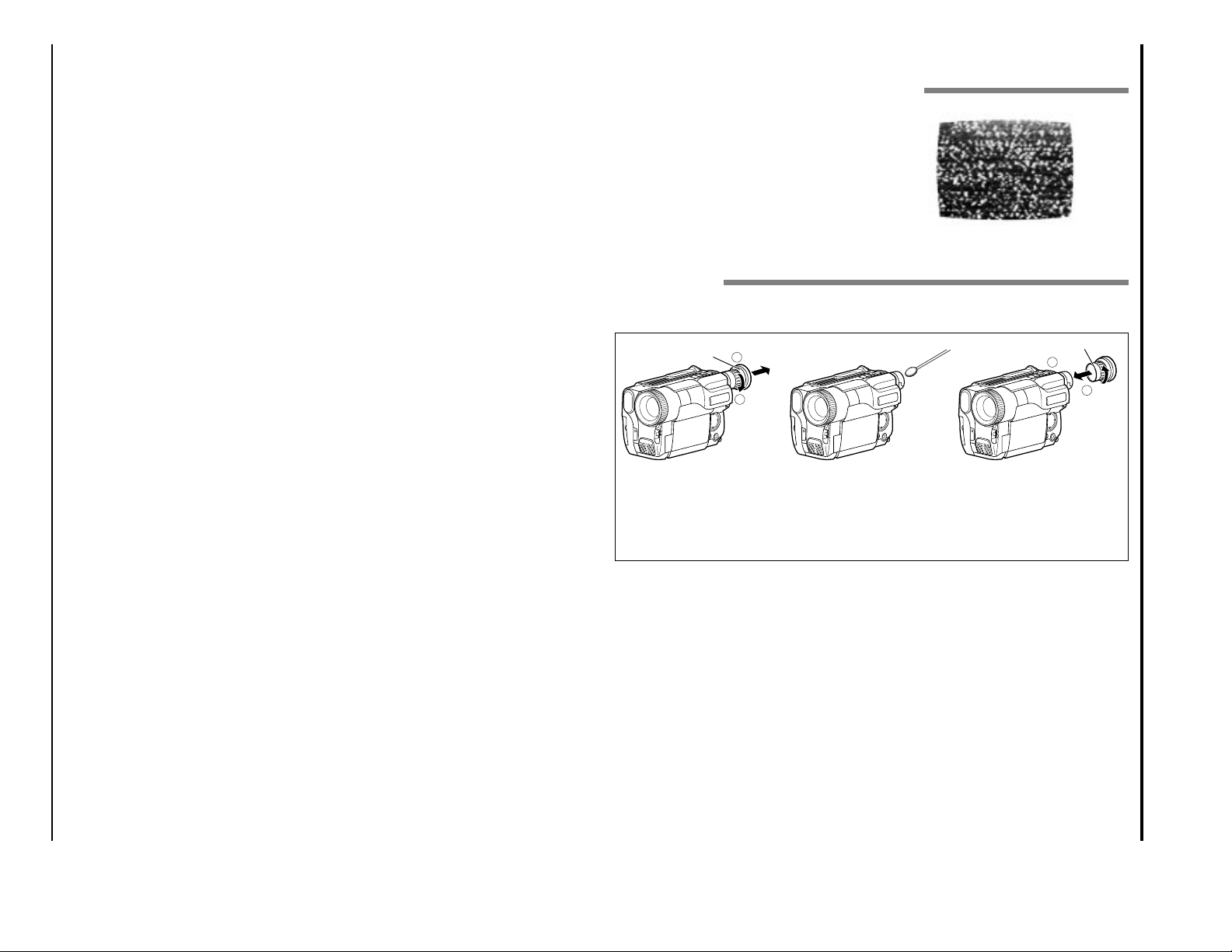
General Maintenance
Cleaning the Camcorder Heads
Dirt can accumulate on the video heads on the
camcorder causing the playback picture to become
blurred or appear as if video information is lost.
This often means that the video heads are dirty.
Use a video head cleaner such as a dry type head
cleaning tape to clean the heads.
If after cleaning the heads the picture does not clear
up consult your nearest dealer or VCR service
center for professional head cleaning.
Cleaning the Lens and Picture Tube of the Electronic
Viewfinder
The lens of the electronic viewfinder can be user-cleaned if dust, dirt, or other foreign matter adheres
to it.
Eye cup
Turn
Pull out
Reference Mark
Push
Turn
1
Turn the eye cup counterclockwise until it stops,
then pull it out to remove.
2
Clean the picture tube face
and lens. To prevent
scratching, use a soft nonabrasive cloth, swab or
lens cleaning paper.
3
Align the reference mark
on eye cup with the top
edge of notch, and push
the eye cup directly; then
turn the eye cup clockwise
to secure it.
1
2
1
2
Memo
CHAPTER 2 DISASSEMBLY
1. BEFORE STARTING DISASSEMBLY
(1) Dismantle and reassemble the mechanism in loading
stop status, except for the following components:
Cassette Lid
Top Cover
Parts on the UH mechanism
Note: After dismantling or resembling the cassette lid
or top cover, return the mechanism to loading
stop status.
(2) For manually operating the mechanism (unloading or
loading), refer to: "How to Operate the Mechanism
Manually".
(3) Dismantle each component according to "1.1
Disassembly Procedure".
(4) For reassembly, perform the reverse procedure to
disassembly when not otherwise specified.
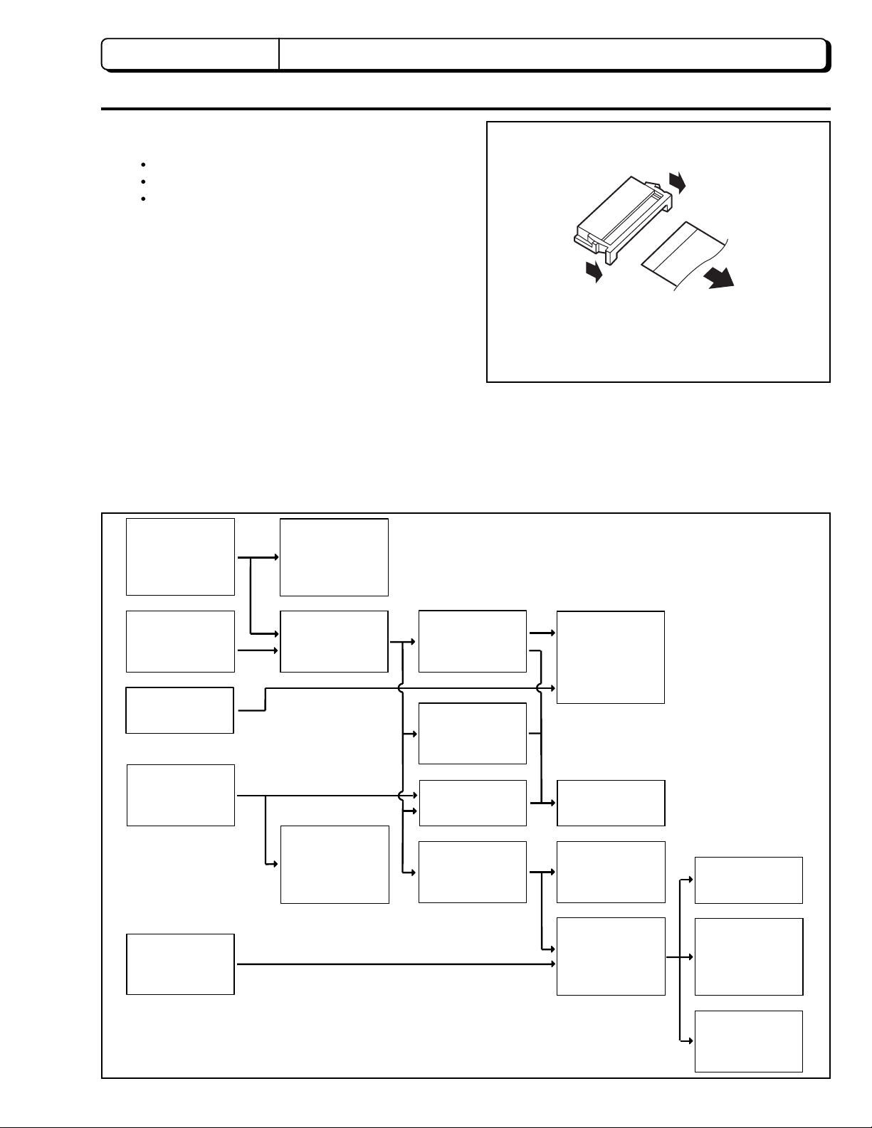
(5) Disconnect flat cables from connectors by the proce
dure shown in Fig. 1-1. Since many circuit boards in
the camera/recorder are connected by in-board
connectors, be sure to follow DISASSEMBLY when
removing the circuit boards.
(1) Release the lock of the connector on the left and right
simultaneously.
(2) Pull out the flat cable.
(1)
(1)
(2)
Fig. 1-1
1.1 Disassembly Procedure
Jack Cover,
Front Cover
Assembly [2.1]
Lens Cover [2.1]
Eye Piece [2.10]
LCD Case-U,
LCD Block [2.3]
PSW Circuit Board,
Microphone Unit,
DC Light,
Front Cover [2.2]
L-Case Assembly,
R-Case Assembly
[2.4]
LCD Circuit Board,
Back Light,
LCD Module,
LCD Case-B [2.9]
EVF Assembly
[2.5]
Speaker,
CON Circuit Board
[2.5]
Fulcrum [2.5]
Camera Chassis
Assembly [2.6]
EVF Case-R,
EVF Case L,
[2.10]
L-Case [2.5]
Lens Frame, Lens,
SE Circuit Board,
CCD Sensor [2.6]
Power Terminal
Unit [2.6]
Cassette Lid,
Top Cover [2.3]
(Note 1)
Note 1: Dismantle or reassemble these parts in loading
stop status; after finishing, return the mechanism
to loading stop status.
VCR Chassis
Assembly,
Jack Unit,
Rear Cover [2.6]
VCA Circuit Board,
Mechanism Frame,
UH Mechanism
[2.7]
Hand Strap,
TW/PW Switch,
R-Case [2.8]
2 - 1
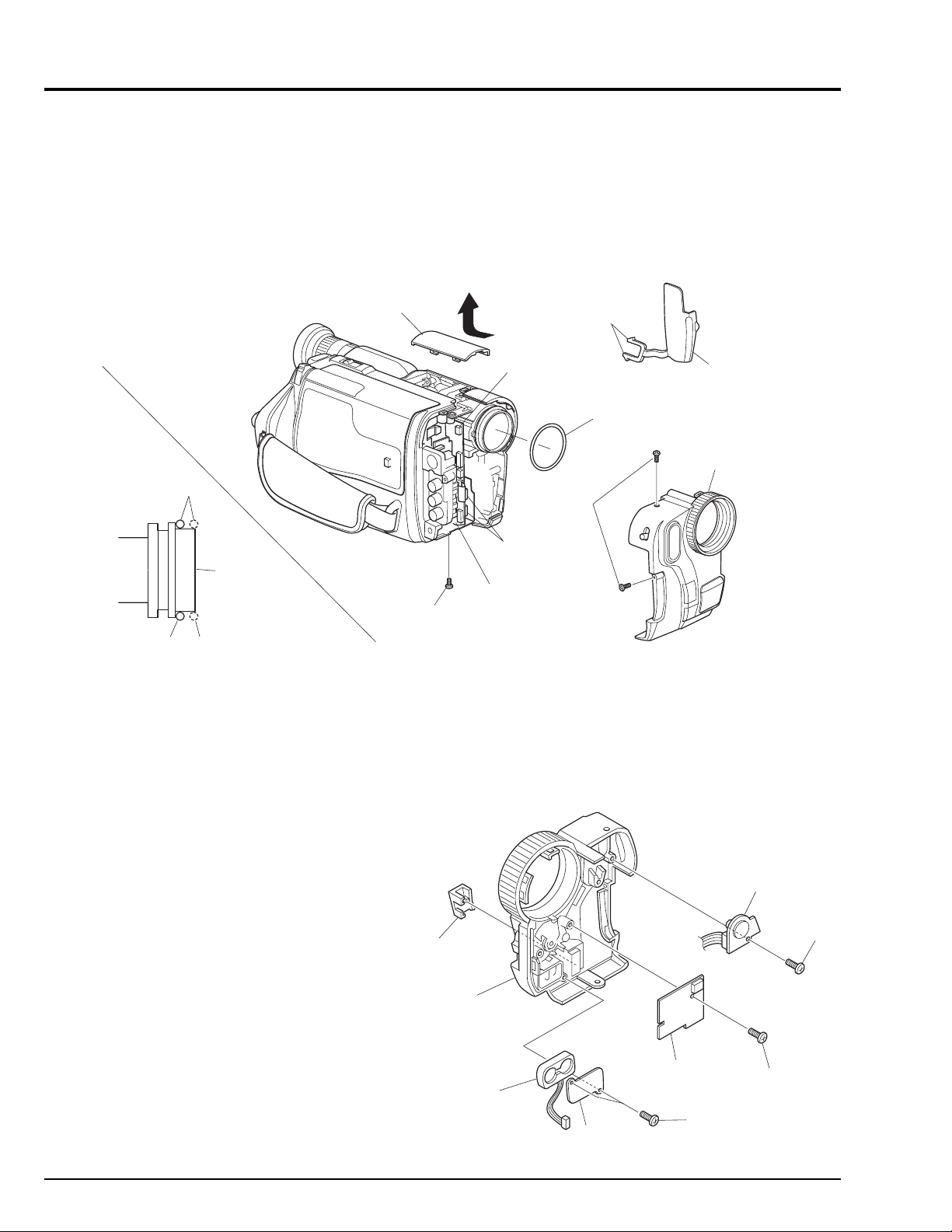
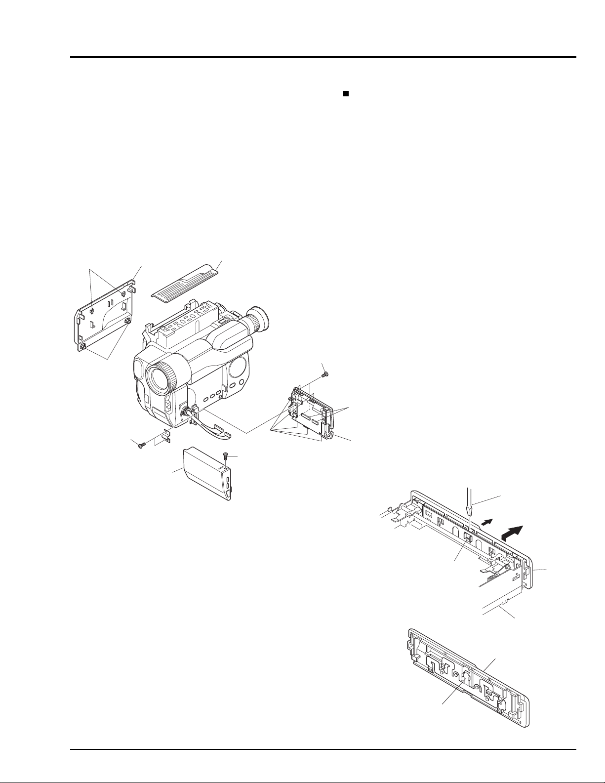
2. CASES AND CIRCUIT BOARDS REMOVAL
2.1 Jack Cover, Front Cover Assembly, Lens Cover (Fig. 2-1)
Note:Some models are not equipped with the DC light.
Cautions:
Be careful not to damage the cables of the microphone.
LENS
COVER
Reinstallation procedure and caution:
The O-ring must be installed in the position shown in Fig.
2-1.
DISCONNECT
CONNECTOR
[For DC LIGHT]
RELEASE
TWO
TABS
O-RING
JACK
COVER
FRONT COVER
ASSMBLY
GOOD
O-RING
NO GOOD
LENS
SURFACE
REMOVE
ONE
SCREW
VCA
CIRCUIT
BOARD
REMOVE
TWO
SCREWS
DISCONNECT
TWO
CONNECTORS
Fig. 2-1
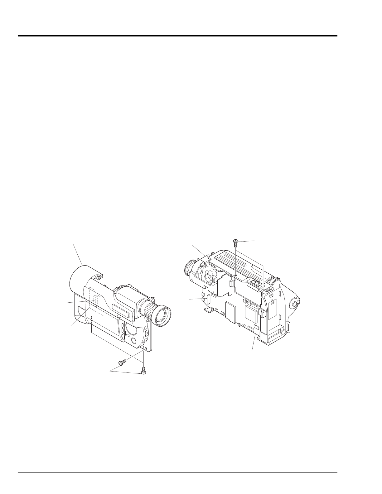
2.2 PSW Circuit Board, Microphone Unit, DC Light, Front Cover (Fig. 2-2)
Note:Some models are not equipped with the DC light.
Reinstallation procedure and caution:
Take care with the orientation of the microphone when
reinstalling it: The red wire is for the left side; the white
lead is for the right side.
ADJ. LID
DC
LIGHT
REMOVE
ONE
SCREW
2 - 2
FRONT
COVER
MICROPHONE
(MIC)
MIC
PLATE
Fig. 2-2
PSW CIRCUIT
BOARD
REMOVE
TWO
SCREWS
REMOVE
ONE
SCREW
2.3 LCD Case-U, LCD Block, Cassette Lid, Top Cover (Figs. 2-3-1, 2-3-2)
(C)
(B)
FLAT-BLADED
SCREW DRIVER
REMOVE
TOP
COVER
TOP
COVER
SUB CHASSIS
PLATE
SPRING
Cautions:
1. Dismantle and reassemble only the cassette lid and top
cover in loading stop status. After work is completed,
return the mechanism to loading stop status.
2. Be careful that the LCD screen is not damaged or
smudged. (If dirt adheres to it, use a soft cloth to wipe it
off.)
3. Handle the LCD module and backlight with extreme
care.
(A)
RELEASE
TWO TABS
CASSETTE
LID
TOP COVER
REMOVE
TWO
SCREWS
Advise of Top Cover Removal
Insert a flat-bladed screwdriver between the top cover and
sub chassis, and push section (B) of the plate spring in the
direction of arrow (C), to remove the top cover in the
direction of the arrow. (See Fig. 2-3-2)
Reinstallation procedure and caution:
To install the cassette lid, first engage sections (A) with the
cassette holder.
REMOVE
TWO
SCREWS
LCD
CASE-U
REMOVE
ONE
SCREW
Fig. 2-3-1
RELEASE
FIVE TABS
DISCONNECT
TWO
CONNECTORS
LCD BLOCK
Fig. 2-3-2
2 - 3
2.4 L-Case Assembly, R-Case Assembly (Fig. 2-4)
Caution:
Be careful so as not to damage the connectors (PG951
and PG731) between the VCA and CON circuit boards.
L-CASE
ASSEMBLY
R-CASE
ASSEMBLY
Reinstallation procedure and caution:
Connect connectors PG951 and PG731 securely.
REMOVE
TWO
SCREWS
2 - 4
PG731
CON
CIRCUIT
BOARD
REMOVE
FOUR
SCREWS
PG951
Fig. 2-4
VCA
CIRCUIT
BOARD
2.5 Electronic Viewfinder (EVF) Assembly, Speaker, CON Circuit Board, Fulcrum, L-Case (Figs. 2-5-1, 2-5-2)
Cautions:
Be careful not to damage the LCD Open/Close switch on
the CON circuit board.
REMOVE
FULCRUM
L-CASE
TWO
SCREWS
DISCONNECT
CONNECTOR
[To SPEAKER]
EVF
ASSEMBLY
Reinstallation procedure and caution:
When reinstalling the EVF assembly, speaker, CON
circuit board and fulcrum, lay out each cable as shown
in Fig. 2-5-2.
DISCONNECT
THREE
CONNECTOR
[To LCD]
S
DISCONNECT
CONNECTOR
[To EVF]
REMOVE
THREE
SCREWS
CON
CIRCUIT
BOARD
REMOVE
THREE
SCREWS
Fig. 2-5-1
SPEAKER
EVF
ASSEMBLY
REMOVE
TWO
SCREWS
SP
BRACKET
SPEAKER
BOSS
CLOTH TAPE
CON CIRCUIT
BOARD
L-CASE
FULCRUM
Fig. 2-5-2
2 - 5
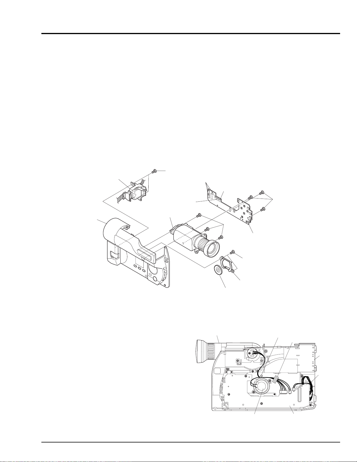
2.6 Camera Chassis Assembly (Lens Frame, Lens, SE Circuit Board, CCD Sensor),
VCR Chassis Assembly, Jack Unit, Rear Cover, Power Terminal Unit (Fig. 2-6)
Cautions:
1. Be careful so as not to damage the connectors (PG201
and PG1001) between the VCA and SE circuit boards.
2. Be careful so as not to damage the connectors
between the VCA circuit board (PG0001) and rear
cover (power terminal unit).
3. Be careful not to damage the crystal filter and CCD
sensor.
REMOVE
ONE
SCREW
VTR CHASSIS
ASSEMBLY
DISCONNECT
FLAT CABLE
DISCONNECT
CAMERA
CHASSIS
ASSEMBLY
FLAT CABLE
Reinstallation procedure and caution:
1. Connect connectors PG201 and PG1001 securely.
2. Connect connectors PG0001 and rear cover (power
terminal unit) securely.
3. The crystal filter is non-directional.
4. Fit in the CCD sensor parallel to the SE circuit board,
fix it with screws, and then solder it.
JACK
UNIT
A
R-CASE
RELEASE
PG201
DISCONNECT
CONNECTOR
ONE TAB
A
REMOVE
THREE
SCREWS
LENS
CRYSTAL
FILTER
SHADING
RUBBER
REMOVE
THREE
SCREWS
LENS
FRAME
CCD
SENSOR
UNSOLDER
FOURTEEN
POINTS
SE
CIRCUIT
BOARD
PG1001
Fig. 2-6
VCA
CIRCUIT
BOARD
REMOVE
TWO
SCREWS
REMOVE
TWO
SCREWS
DISCONNECT
FLAT CABLE
PG0001
REMOVE
ONE
SCREW
POWER
TERMINAL
UNIT
RELEASE
THREE
TABS
REAR
COVER
REMOVE
ONE
SCREW
2 - 6
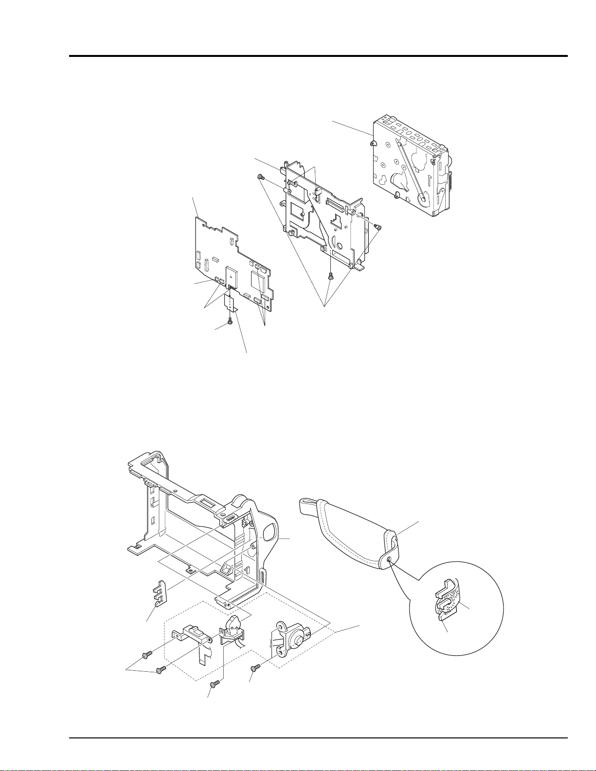
2.7 VCA Circuit Board, Meacanism Frame, UH Mechanism (Fig. 2-7)
UH
MECHANISM
VCA CIRCUIT
BOARD
DISCONNECT
CONNECTOR
DISCONNECT
TWO
FLAT CABLES
REMOVE
ONE
SCREW
MECHANISM
FRAME
HEAD
SHIELD
DISCONNECT
THREE
FLAT CABLES
RELEASE
TWO TABS
REMOVE
THREE
SCREWS
Fig. 2-7
2.8 Hand Strap, TW/PW Switch, R-Case (Fig. 2-8)
REMOVE
TWO
SCREWS
HOLDER
REMOVE
ONE
SCREW
REMOVE
TWO
SCREWS
R-CASE
Fig. 2-8
Cautions:
Be careful not to damage the flat cable of the TW/PW
switch.
HAND
STRAP
TW/PW
SWITCH
HOLDER
HAND
STRAP
2 - 7
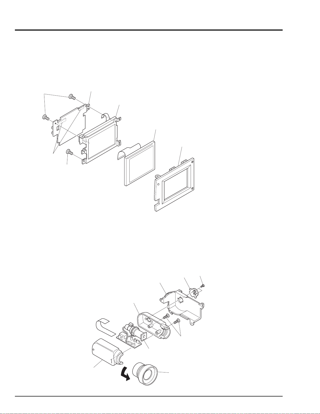
2.9 LCD Circuit Borad, Back Light, LCD Module, LCD Case-B (Fig. 2-9)
Cautions:
1. Be careful that the LCD screen is not damaged or
smudged. (If dirt adheres to it, use a soft cloth to wipe it
off.)
2. Handle the LCD module and backlight with extreme
care.
LCD
MODULE
LCD CASE-B
REMOVE
TWO
SCREWS
DISCONNECT
TWO
FLAT CABLES
REMOVE
ONE
SCREW
LCD
CIRCUIT
BOARD
BACK
LIGHT
Fig. 2-9
2.10 EVF Case-R, EVF Case-L, Eye Piece (Fig. 2-10)
Cautions:
1. Be careful not to damage the CRT.
EVF
BASE
EVF
CASE-R
CRT
TURN
BASE
REMOVE
TWO
SCREWS
REMOVE
TWO
SCREWS
2 - 8
EVF
CASE-L
EYE PIECE
Fig. 2-10
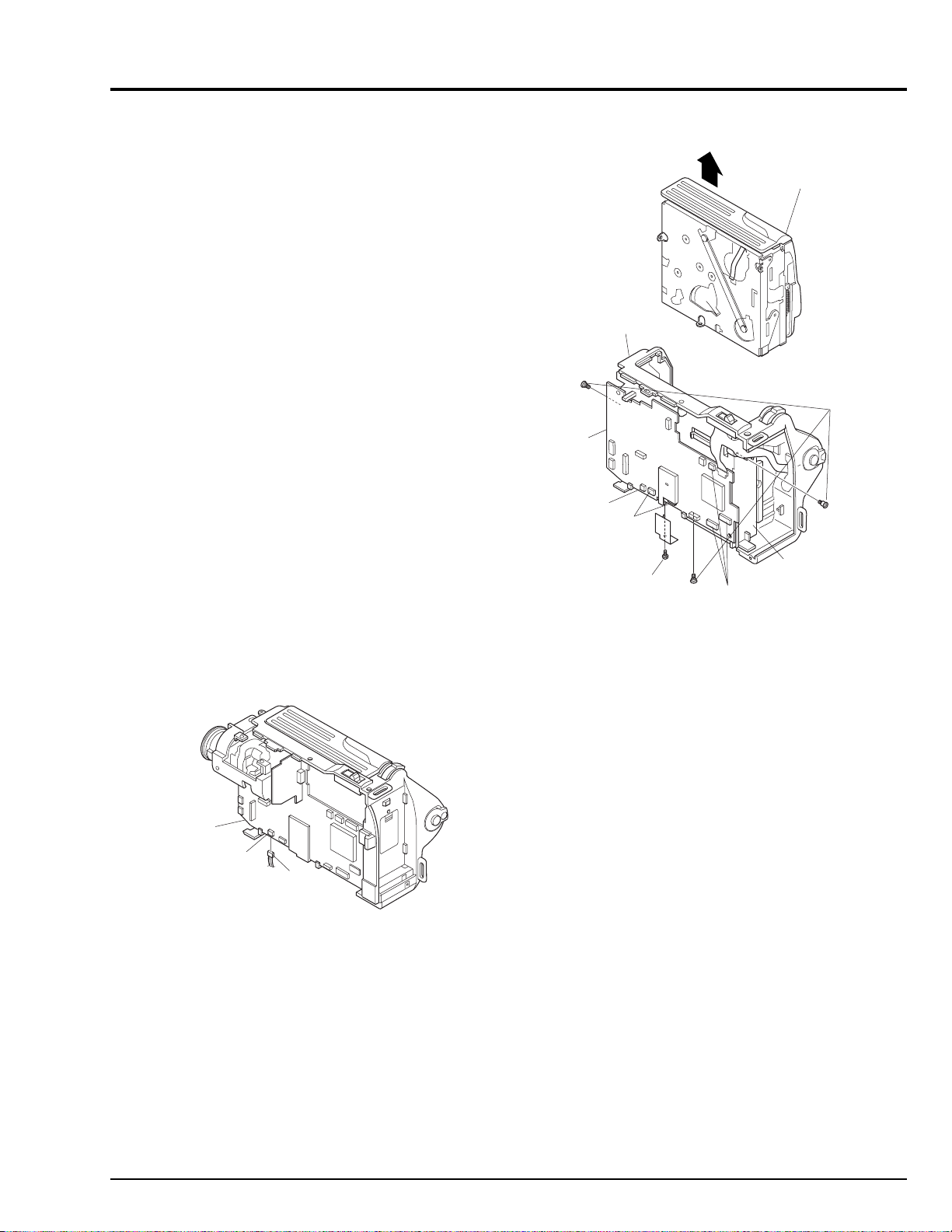
3. HOW TO OPERATE THE MECHANISM MANUALLY
CAUTION
Perform this procedure for emergency only when
normal loading or unloading is not possible because
the electrical circuits or loading motor is defective.
(1) Remove the r-case assembly. (See Figs. 2-4-1,
2-4-2)
(2) Disconnect connector (CN604) from PG604 on the
VCA circuit board, and supply 4V DC to CN604
(directly to the loading motor). (See Fig. 3-1)
Connecting CN604 brown wire (+) and red wire (-)
results in unloading.
Connecting CN604 red wire (+) and brown wire (-)
results in loading.
R-CASE
UH
MECHANISM
Note: To unload the mechanism with a tape inserted,
manually turn the capstan motor simultaneously
to take up the tape.
If loading or unloading does not occur even when 4V DC is
directly supplied to the loading motor, perform the following procedure:
(3) Remove the camera chassis assembly and rear
cover. (See Fig. 2-6)
Note: Note that it is difficult to remove the rear cover.
VCA
CIRCUIT
BOARD
PG604
CN604
Fig. 3-1
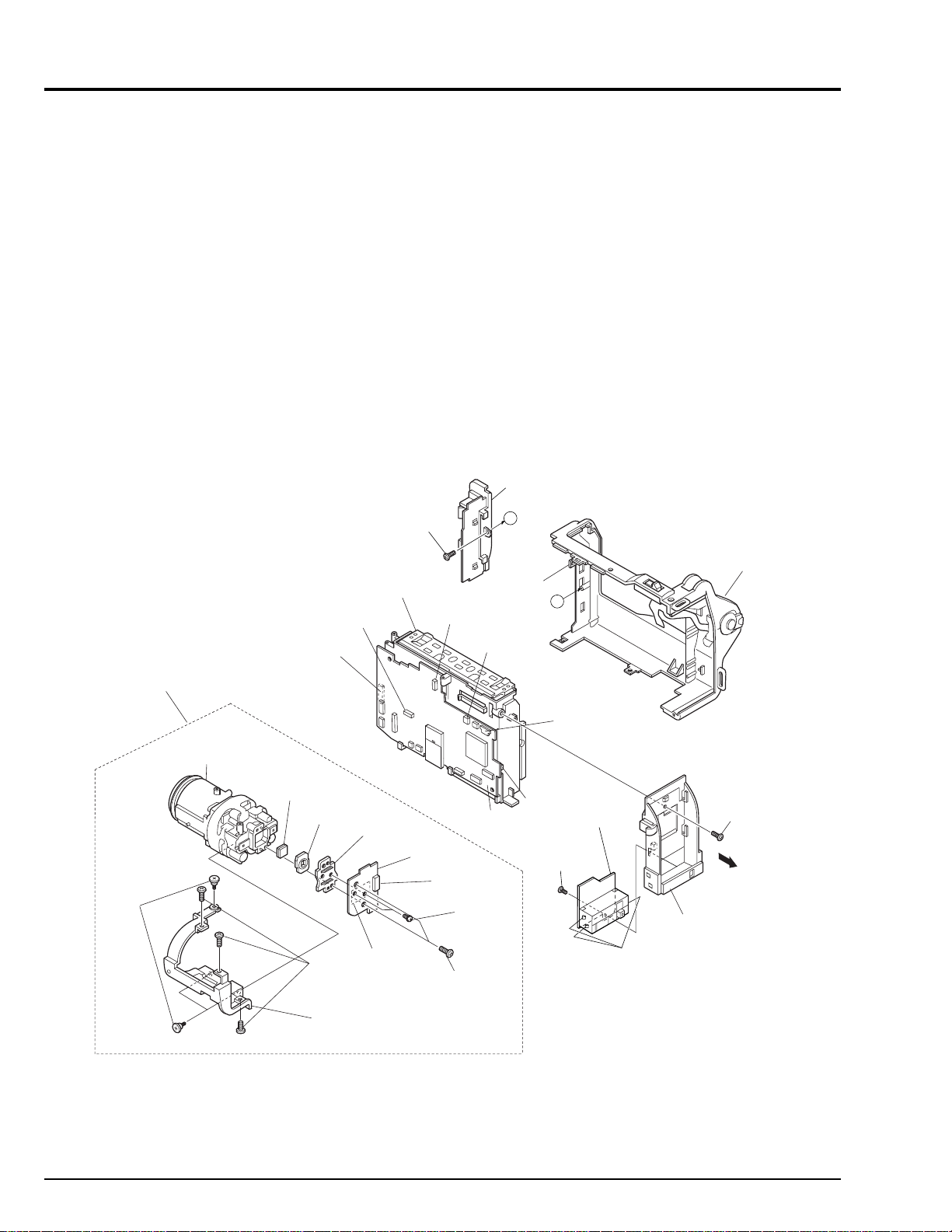
(4) Disconnect 3 flat cables. (See Fig. 3-2)
(5) Disconnect connector. (See Fig. 3-2)
(6) Remove 1 screw holding the head shield. (See Fig.
3-2)
(7) Disconnect 2 flat cables. (See Fig. 3-2)
(8) Remove 3 screws. (See Fig. 3-2)
(9) Remove the UH mechanism in the direction of the
arrow from the r-case. (See Fig.3-2)
(10) Remove the cassette lid and top cover. (See Figs.
2-3-1, 2-3-2)
REMOVE
THREE
VCA
CIRCUIT
BOARD
DISCONNECT
CONNECTOR
DISCONNECT
TWO FLAT
CABLES
REMOVE
ONE
SCREW
MECHANISM
FRAME
DISCONNECT
THREE
FLAT CABLES
SCREWS
Fig. 3-2
(11) Release 2 tabs and pull out the loading motor from
the loading motor holder. (See Fig. 3-3)
Note: The above removal is different from normal
removal. In normal circumstances, remove the
loading motor assembled with the loading motor
holder. (The loading motor and loading motor
holder comprise an assembly.)
(12) Turn over the mechanism. (See Fig. 3-3)
Note: Do not turn over with the idler cover removed.
(13) Use a flat-bladed screwdriver, etc. to turn cam gear
(A) or (B). (See Fig. 3-3)
Turning it in the direction of the arrow will unload the
mechanism, and turning it in the opposite direction to
the arrow will load the mechanism.
Notes: 1. Be careful not to damage the cam gears.
2. To unload the mechanism with a tape inserted,
manually turn the capstan motor simultaneously
to take up the tape.
2 - 9
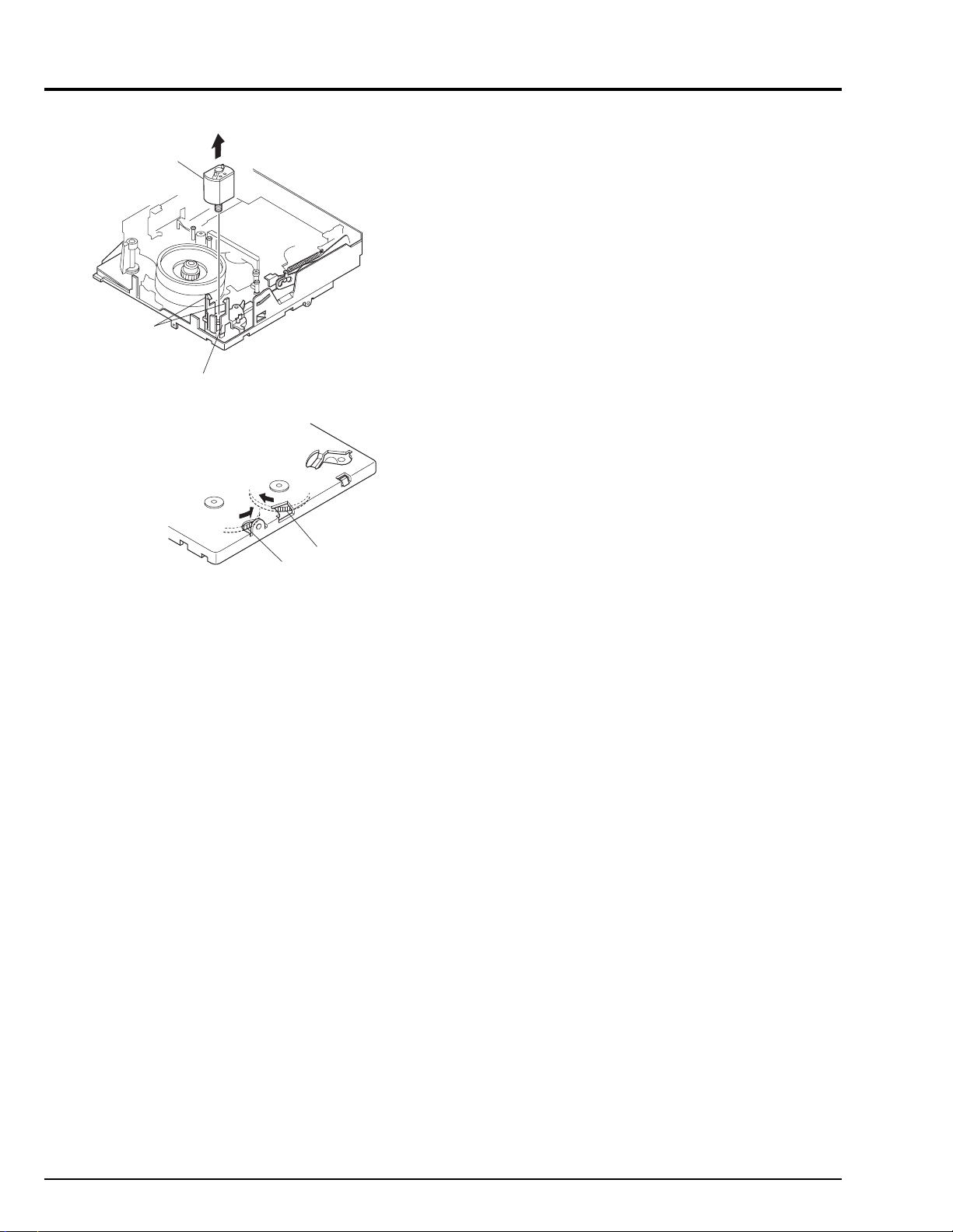
LOADING
MOTOR
RELEASE
TWO
TABS
LOADING
MOTOR
HOLDER
CAM
GEAR
(B)
CAM
GEAR
(A)
Memo
Fig. 3-3
2 - 10
CHAPTER 3 ELECTRIC CIRCUIT ADJUSTMENT
Trademark
MS-DOS is a registered trademark of Microsoft
Corporation.
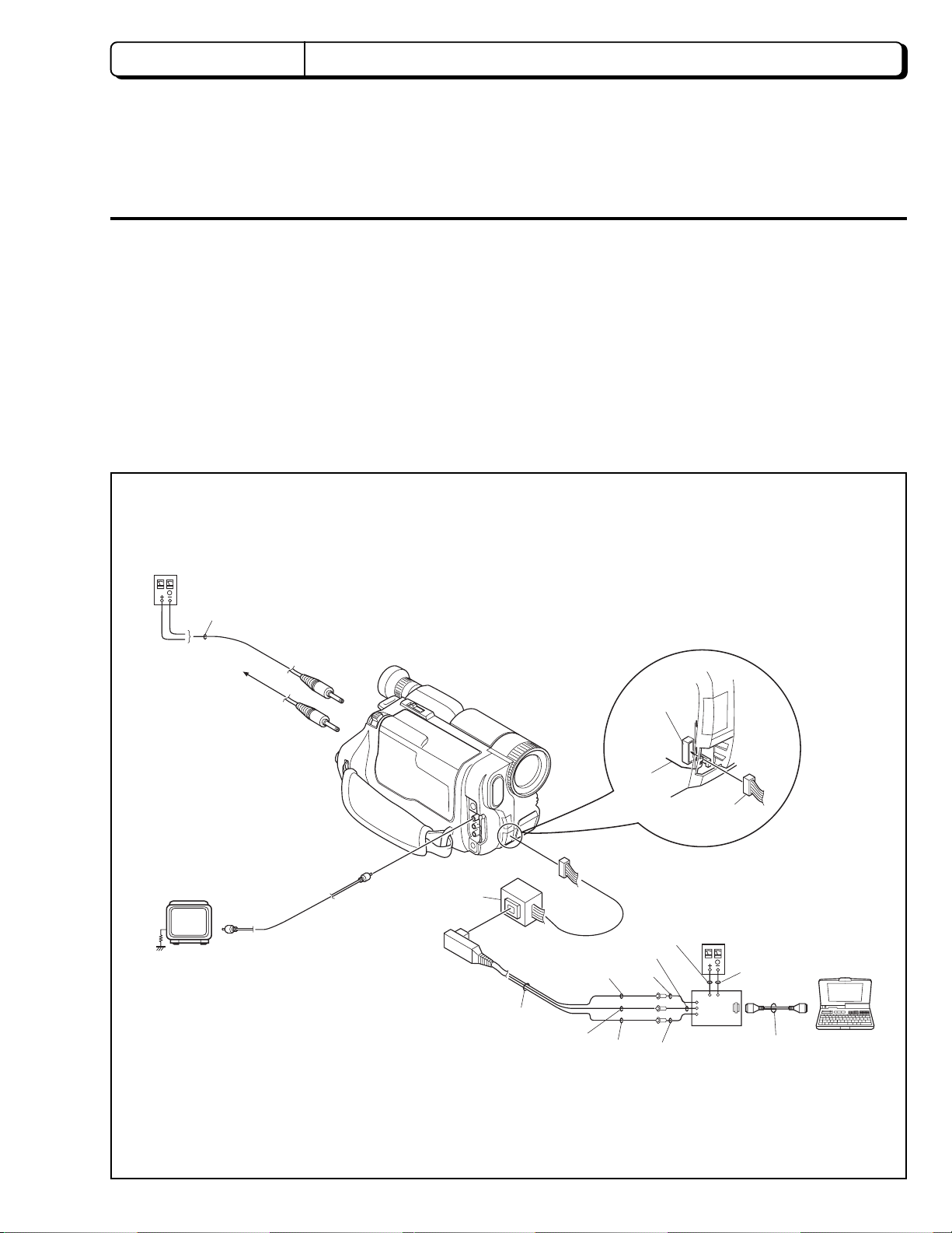
1. CONNECTION FOR ADJUSTMENT
1.1 Before Starting Adjustment
(1) Set the date. (If the camera/recorder is left for
several minutes with no date set after power is
turned on, it will automatically enter the demo mode.)
Notes: 1. Perform the electric circuit adjustments using a
personal computer.
DC POWER
SUPPLY
(0-8V/3A)
Abbreviation
MAP:Digital adjustment program.
DSP: Digital signal processor
2. It is not necessary to remove cases for electric
circuit adjustments.
3. The ODC DC cord is a jig which is to be used in
the Power Shut Off Level (ODC) Adjustment.
For other adjustments, the AC adapter can be
used as a power supply.
ODC DC CABLE
[For ODC Adj.]
To AC ADAPTER
COLOR
VIDEO
MONITER
8 - 20PIN
EXTENSION
CABLE
DSP AV
OUTPUT
JIG
YEL
BLK
WHT
PG905
VCA
CIRCUIT
BOARD
RED
YEL
BLK
WHT
8-20PIN
EXTENSION
CABLE
DC POWER
SUPPLY
(5V/1A)
BLK
DSP-R JIG
PERSONAL
COMPUTER
RS232-C
CABLE
Fig. 1-1 Connection for adjustment
3 - 1
2. CAMERA SECTION ADJUSTMENT
2.1 Test Equipment Necessary for Adjustment
Oscilloscope (dual trace) [& Vectorscope]
Digital Voltmeter (DVM)
Color Video Monitor
Adjustment Floppy Disk
Personal Computer
Personal Computer 9-pin or 25-pin (RS232C) Cable
DSP-R Jig
DSP AV Output Jig
8 - 20 Pin Extension Cable
Light Box (3100 K)
Light Balancing Filter C12
DC Power Supply (DC5 V/1 A)
AC Adapter or
DC power supply (DC7 V/3 A) and ODC DC code
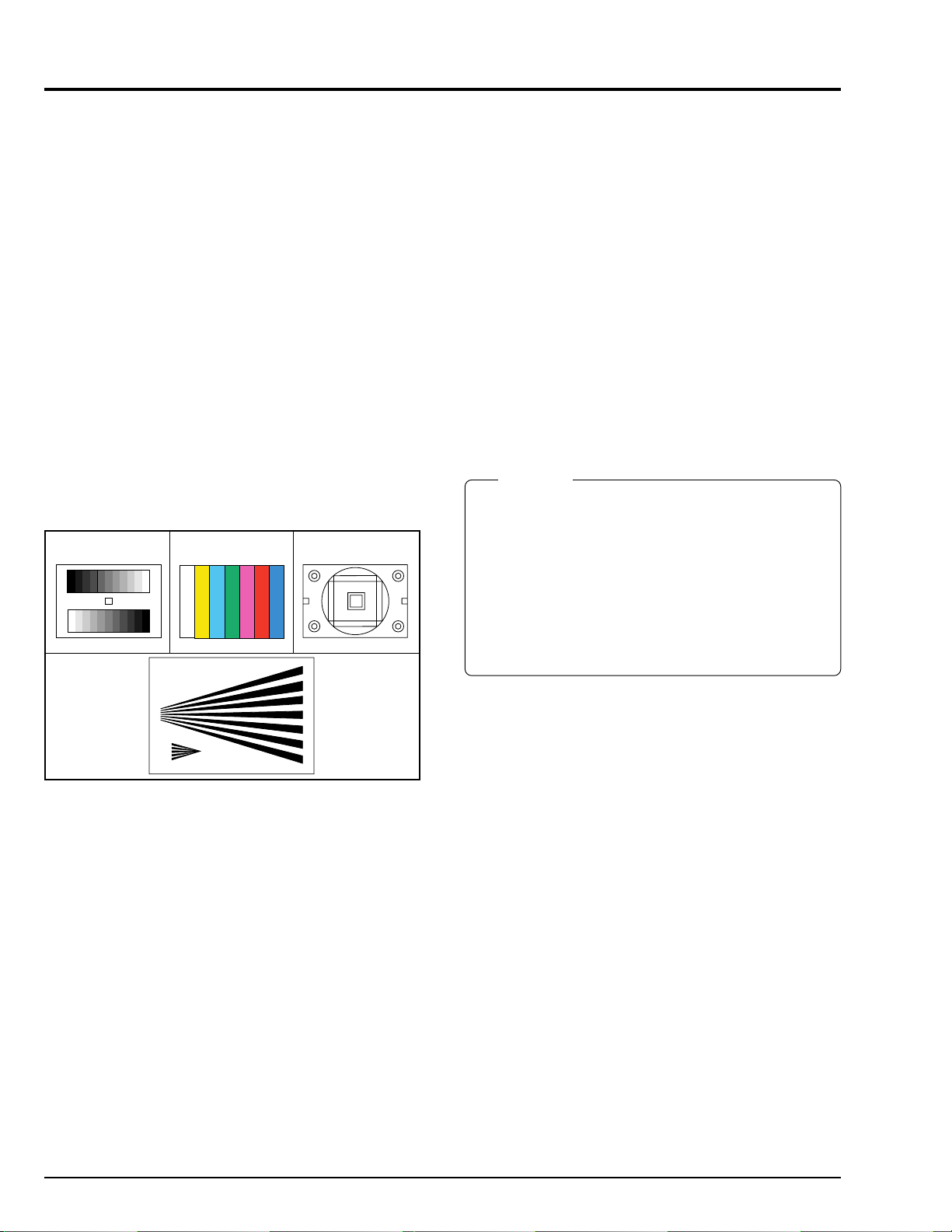
2.2 List of Charts for Camera Adjustment
Table 2-1
Gray Scale Chart
Backfocus
Adjustmant
Chart
Color Bar Chart
Resolution Chart
2.4 Preset Positions of Switches and Controls During Adjustment
Note: Some models do not have switches (modes)
marked "#".
CAM/OFF/VIDEO switch
SUB POWER switch
DC LIGHT switch [#]
................................................
DATE
................................................
TITLE
EFFECT
BLC
MENU
EIS on the MENU [#]
PROGRAM AE [#]
FOCUS
FADE
............................................
...................................................
...............................................
.............................................
................................................
Caution
1. Since the adjustment program is subject to change
for improvements, computer displays may be
different from those shown in this manual. In such
cases, follow the computer displays for adjustment.
2. The computer displays may be different from those
shown in this manual, depending on the destination
of models and whether or not certain functions are
provided. In such cases, follow the computer displays
for adjustment.
..................
.........................
.........................
........................
............................
"CAM" position
"STANDBY" position
"OFF" position
Not display mode
Not display mode
OFF mode
OFF mode
Not display
OFF mode
AUTO mode
Autofocus mode
OFF mode
2.3 Adjustment Conditions
1. Check that the VCR section has been adjusted
correctly before adjusting the camera section.
2. Use a light box with minimum flickering.
Control the color temperature of the light box strictly.
3. When using the video out jack to perform adjustment,
be sure to terminate the video out jack with 75 ohms.
4. Place the light box approx. 30 cm away from the
camera (lens surface) when otherwise not specified.
5. Point the camera at the chart to full the video period
when otherwise not specified.
6. Use the 10:1 probe of the oscilloscope when otherwise
not specified.
7. When "Trigger the oscilloscope internally" is specified,
set the time base of the oscilloscope to 10µs/div.
3 - 2
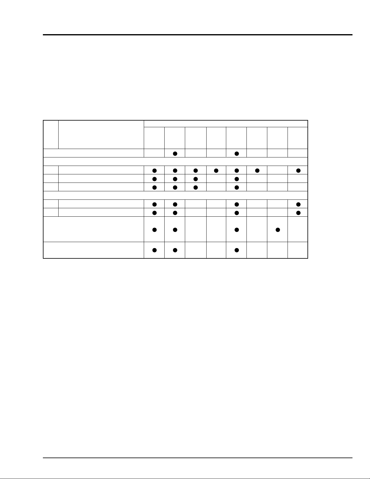
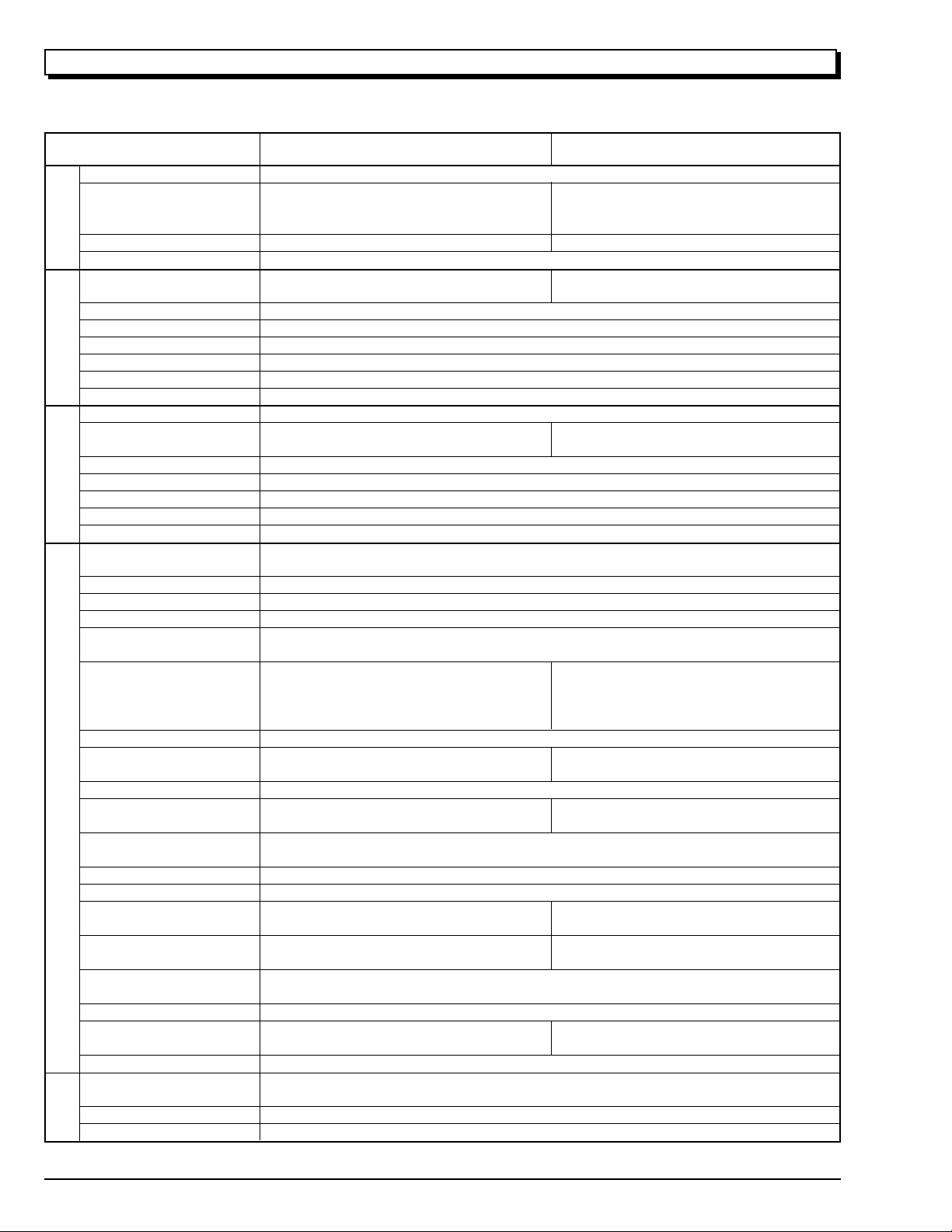
2.5 Check After Replacing Major Components in the Camera Section
After replacing major components, perform adjustments, referring to the table below.
The following table shows the minimum adjustments required after major components are replaced.
The table below may not apply when several components are replaced, depending on the symptom of the defect.
Caution: When EEPROM or the VCA circuit board is replaced, initialize the EEPROM, referring to "2.6.3 Initial
Setting by Model" then perform all the camera section and system control/servo circuits adjustments.
Table 2-2
ITEM NAME OF MAJOR COMPONENTS
No. NAME OF ADJUSTMENT SE VCA IC1001 IC1104 IC1105 IC1201 IC1401 Lens
Circuit Circuit IC1402 Block
Board Board IC1403
INITIAL SETTING BY MODEL
DIGITAL ADJUSTMENT PROCEDURE
(1) Auto Iris Control Adjustment
(2) White Balance Adjustment
(3) Chroma Gain Adjustment
AUTOFOCUS ADJUSTMENT PROCEDURE
(1) Zoom Trace Adjustment
(2) AF Noise Level Adjustment
STABILIZER ADJUSTMENT
PROCEDURE
LE(AU)/E578LE(SW)]
SPOT NOISE ADJUSTMENT
PROCEDURE
[Except for VM-E578
2.6 Adjustment Procedure
Notes: 1. To complete adjustment, press the [ESC]
(escape) key twice to restore the MS-DOS
screen and then turn off the camera/recorder
and jig.
2. The following describes an example of the
instructions of the personal computer and the
menu display; they are different depending on
the personal computer manufacturer and model.
Refer to the instruction manual of personal
computer.
3. When the error message appears during
adjustment, refer to "4. Error Message".
If a key is pressed after an error message
appears, the ADJUSTMENT MENU is restored.
2.6.1 Connections for Adjustment
Connect the camera/recorder, DSP jig, personal computer,
power supply, etc. as shown in Fig. 1-1.
Check that the camera/recorder is turned on.
3 - 3
 Loading...