

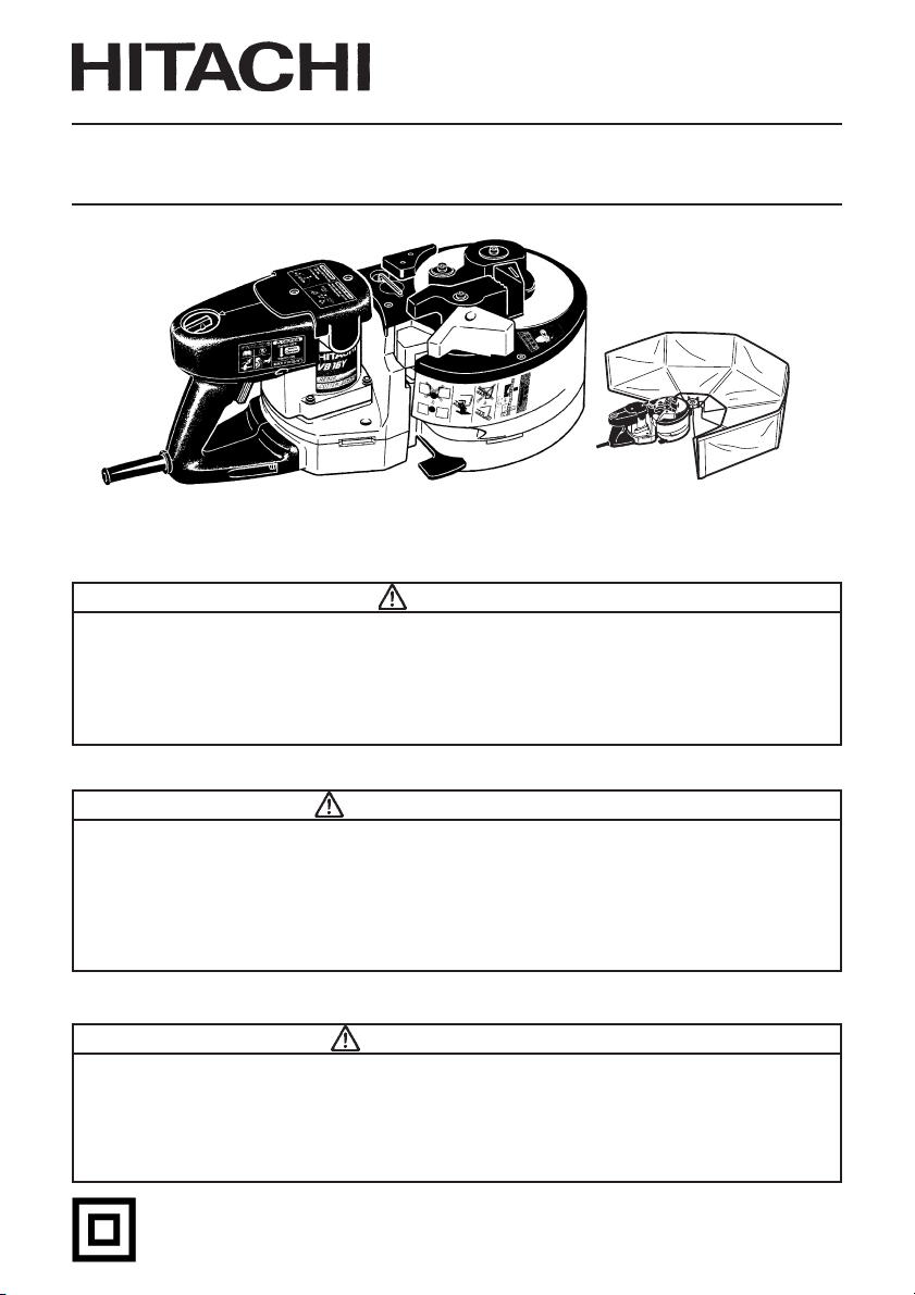
MODEL REBAR CUTTER/BENDER
MODÈLE
MODELO CORTADORA DOBLADORA DE VARILLA
VB 16Y
CISAILLE/CINTREUSE POUR BARRES BÉTON
SAFETY INSTRUCTIONS AND INSTRUCTION MANUAL
WARNING
IMPROPER OR UNSAFE use of this power tool can result in death or serious bodily
injury!
This manual contains important information about product safety. Please read
and understand this manual BEFORE operating the power tool. Please keep this
manual available for other users and owners before they use the power tool.
This manual should be stored in safe place.
INSTRUCTIONS DE SECURITE ET MODE D’EMPLOI
AVERTISSEMENT
Une utilisation INCORRECTE OU DANGEREUSE de cet outil motorisé peut entraîner
la mort ou de sérieuses blessures corporelles!
Ce mode d’emploi contient d’importantes informations à propos de la sécurité de
ce produit. Prière de lire et de comprendre ce mode d’emploi AVANT d’utiliser
l’outil motorisé. Garder ce mode d’emploi à la disponibilité des autres utilisateurs
et propriétaires avant qu’ils utilisent l’outil motorisé. Ce mode d’emploi doit être
conservé dans un endroit sûr.
INSTRUCCIONES DE SEGURIDAD Y MANUAL DE INSTRUCCIONES
ADVERTENCIA
¡La utilización INAPROPIADA O PELIGROSA de esta herramienta eléctrica puede
resultar en lesiones de gravedad o la muerte!
Este manual contiene información importante sobre la seguridad del producto.
Lea y comprenda este manual ANTES de utilizar la herramienta eléctrica. Guarde
este manual para que puedan leerlo otras personas antes de utilizar la herramienta
eléctrica. Este manual debe ser guardado en un lugar seguro.
DOUBLE INSULATION
DOUBLE ISOLATION
AISLAMIENTO DOBLE

English
IMPORTANT INFORMATION ..................... 3
MEANINGS OF SIGNAL WORDS............... 3
SAFETY ............................................................4
INPORTANT SAFETY INSTRUCTIONS
FOR USING POWER TOOLS ................. 4
SPECIFIC SAFETY RULES AND SYMBOLS ...
REPLACEMENT PARTS .............................. 7
USE PROPER EXTENSION CORD .............. 8
DOUBLE INSULATION FOR SAFER
OPERATION............................................ 9
FUNCTIONAL DESCRIPTION ....................... 10
NAME OF PARTS .......................................... 10
SPECIFICATIONS .......................................... 11
CONTENTS
Page
ASSEMBLY AND OPERATION ..................... 12
APPLICATIONS ......................................... 12
PRIOR TO OPERATION ............................. 12
PICTGRAPH ILLUSTRATION AND
EXPLANATION ..................................... 13
6
HOW TO USE (CUTTING) ......................... 15
SERVICE LIFE AND REPLACEMENT
OF THE CUTTER................................... 16
HOW TO USE (BENDING) ........................ 17
MAINTENANCE AND INSPECTION ............. 21
ACCESSORIES .............................................. 22
STANDARD ACCESSORIES ..................... 22
OPTIONAL ACCESSORIES ....................... 22
Page
Français
INFORMATIONS IMPORTANTES ............ 23
SIGNIFICATION DES MOTS
D’AVERTISSEMENT ............................. 23
SECURITE ......................................................24
CONSIGNES DE SÉCURIT´E RELATIVES
AUX OUTILS ÉLECTRIQUES ............... 24
REGLES DE SECURITE SPECIFIQUES ET SYMBOLES
PIECES DE RECHANGE ............................ 27
UTILISER LE CORDON DE RALLONGE APPROPRIÉ .
DOUBLE ISOLATION POUR UN
FONCTIONNEMENT PLUS SUR ......... 29
DESCRIPTION FONCTIONNELLE................. 30
NOM DES PARTIES................................... 30
SPECIFICATIONS ...................................... 31
Español
INFORMACIÓN IMPORTANTE .................44
SIGNIFICADO DE LAS PALABRAS DE
SEÑALIZACIÓN ....................................44
SEGURIDAD .................................................. 45
NORMAS DE SEGURIDAD PARA LAS
HERRAMIENTAS ELÉCTRICAS .............
NORMAS Y SÍMBOLOS ESPECÍFICOS DE SEGURIDAD
PIEZAS DE REEMPLAZO .......................... 48
UTILICE EL CABLE PROLONGADOR ADECUADO ........
AISLAMIENTO DOBLE PARA OFRECER
UNA OPERACIÓN MÁS SEGURA ....... 50
DESCRIPCIÓN FUNCTIONAL ....................... 51
NOMENCLATURA ..................................... 51
ESPECIFICACIONES .................................. 52
TABLE DES MATIERES
Page
.26
28
ÍNDICE
Página
45
... 47
49
ASSEMBLAGE ET FONCTIONNEMENT ...... 32
Page
APPLICATIONS ......................................... 32
AVANT L’UTILISATION ............................ 32
SCHÉMA ET EXPLICATION ...................... 33
UTILISATION (COUPE) ............................. 35
DURÉE DE SERVICE ET REMPLACEMENT
DU COUTEAU ......................................36
UTILISATION (CINTRAGE) ....................... 37
ENTRETIEN ET INSPECTION ....................... 42
ACCESSOIRES .............................................. 43
ACCESSOIRES STANDARD ..................... 43
ACCESSOIRES SUR OPTION ................... 43
Página
MONTAJE Y OPERACIÓN ............................ 53
APLICACIONES ......................................... 53
ANTES DE LA OPERACIÓN ...................... 53
ILUSTRACION PICTRORICA Y
EXPLICACION ....................................... 54
NOTAS SOBRE EL USO (CORTADORA) . 56
VIDA DE SERVICIO Y REEMPLAZO DE LA
CORTADORA ........................................57
NOTAS SOBRE EL USO (CURVADORA) . 58
MANTENIMIENTO E INSPECCIÓN .............. 63
ACCESORIOS ................................................ 64
ACCESORIOS ESTÁNDAR ....................... 64
ACCESORIOS OPCIONALES .................... 64

English
IMPORTANT INFORMATION
Read and understand all of the operating instructions, safety precautions and warnings in
the Instruction Manual before operating or maintaining this power tool.
Most accidents that result from power tool operation and maintenance are caused by the
failure to observe basic safety rules or precautions. An accident can often be avoided by
recognizing a potentially hazardous situation before it occurs, and by observing appropriate
safety procedures.
Basic safety precautions are outlined in the “SAFETY” section of this Instruction Manual and
in the sections which contain the operation and maintenance instructions.
Hazards that must be avoided to prevent bodily injury or machine damage are identified by
WARNINGS on the power tool and in this Instruction Manual.
Never use this power tool in a manner that has not been specifically recommended by
HITACHI, unless you first confirm that the planned use will be safe for you and others.
MEANINGS OF SIGNAL WORDS
WARNING indicates a potentially hazardous situation which, if ignored, could result in
serious personal injury.
CAUTION indicates a hazardous situation which, if ignored, could result in moderate
personal injury, or could cause machine damage.
NOTE emphasizes essential information.
3

English
SAFETY
INPORTANT SAFETY INSTRUCTIONS FOR USING ALL POWER TOOLS
READ ALL OF THE WARNINGS AND OPERATING INSTRUCTIONS IN THIS MANUAL
BEFORE OPERATING OR MAINTAINING THIS TOOL:
WARNING: When using this electric tool, take all necessary precautions to minimize
the risk of electric shock or other personal injury.
In particular, always comply with the following safety rules:
1. ALWAYS KEEP GUARDS IN PLACE and in working order.
2. ALWAYS REMOVE ADJUSTING KEYS AND WRENCHES BEFORE STARTING TOOL.
Always confirm that all keys and adjusting wrenches have been removed from the tool
before it is turned on.
3.ALWAYS KEEP WORK AREA CLEAN. Avoid injuries by not cluttering the work areas and
work benches.
4. NEVER USE TOOL IN HAZARDOUS ENVIRONMENTS. Never use the power tool in damp
or wet places and never expose it to rain. Always keep the work area well lighted.
5. NEVER PERMIT CHILDREN OR OTHERS TO LOITER NEAR THE WORK AREA. Keep all
people (especially children) away from the work area. Always unplug unattended tools
and keep the work place tamper-proof by installing locks on the doors and on the master
switches. Always remove the lock-off button from the tool and store it in a secure place,
when the tool is not in use.
6. NEVER FORCE THE TOOL. It will do the job better and more safely if it is operated at the
rate for which it was designed.
7.ALWAYS USE THE RIGHT TOOLS. Never force a tool or an attachment to do a job for
which it was not designed.
8. ALWAYS WEAR PROPER APPAREL WHEN WORKING WITH THE TOOL. Never wear
loose clothing, gloves, neckties, rings, bracelets or other jewelry which may get caught
in the moving parts. Always wear non-slip footwear, preferably with steel toes. Wear
protective hair covering to contain long hair.
9. ALWAYS USE EYE PROTECTION WHEN WORKING WITH THE TOOL TO PREVENT EYE
INJURY. Ordinary eyeglasses do not provide adequate protection because the lenses are
not made of safety glass. Also, use a face mask for additional safety and wear a dust mask
if the cutting/bending operation produces dust.
10. ALWAYS SECURE THE WORKPIECE TO THE FENCE OR THE TABLE. Use clamps or a vise
to hold the workpiece in place. It is safer than using your hand and it frees both hands to
operate the tool.
11. NEVER OVERREACH. Always keep proper footing and balance when working with the
tool.
12. ALWAYS MAINTAIN TOOLS WITH CARE. Always keep tools sharp and clean for the best
and safest performance. Always follow instructions for lubricating the tool and for
changing accessories.receptacle.
4

English
13. ALWAYS DISCONNECT THE TOOL before servicing and before changing blades or other
accessories.
14. NEVER RISK UNINTENTIONAL STARTING WHEN PLUGGING IN THE TOOL. Always
confirm that the switch is in the OFF position before inserting the power plug into the
15. ALWAYS USE RECOMMENDED ACCESSORIES ONLY WHEN OPERATING THIS TOOL.
Consult this instruction manual for descriptions of recommended accessories. To avoid
personal injuries, use only recommended accessories in conjunction with this tool.
16. NEVER STAND ON THE TOOL. Prevent serious injury by not tipping the tool and by not
risking unintentional contact with the cutter.
17. ALWAYS CHECK FOR DAMAGED PARTS BEFORE USING THE TOOL. Always check the
guard and all other components for damage before using the tool to assure that they will
function properly. Check all moving parts for proper alignment, freedom from binding
and other conditions that might affect proper operation. Always repair or replace any
damaged guards or other damaged components before using the tool.
18. ALWAYS CONFIRM THE ROTATION DIRECTION OF THE BLADE BEFORE USING THE
TOOL. Always feed work into the tool against the moving direction of the cutter in order
to prevent possible injury.
19. NEVER LEAVE THE TOOL RUNNING WHILE UNATTENDED. TURN POWER OFF. Do not
leave tool until it comes to a complete stop. Always turn the power off when the tool is
not in use. Always unplug the power cord when the tool is not in use.
20. This tool was not designed to be used for mass-production applications and should not
be used in mass-production environments.
21. When servicing this tool, use only authorized replacement parts.
22. Apply 120 volts AC only to this tool. Applying the wrong voltage or applying DC power
can cause the POWER TOOL to operate improperly and cause serious personal injury or
damage to the tool.
23. POLARIZED PLUGS To reduce the risk of electric shock, this equipment has a polarized
plug (one blade is wider than the other). This plug will fit in a polarized outlet only one
way. If the plug does not fit fully in the outlet, reverse the plug. If it still does not fit, contact
a qualified electrician to install the proper outlet. Do not change the plug in any way.
5

English
SPECIFIC SAFETY RULES AND SYMBOLS
WARNING: For Your Own Safety Read Instructon Manual Before Operating Tool.
Wear Eye Protection.
Risk of injury due to accidental starting.
Do not use in a home workshop or other work area where children may
be present.
1. Hold tools by insulated gripping surfaces when performing an operation where the tool
may contact hidden wiring or its own cord. Contact with a “live” wire will make exposed
metal parts of the tool “live” and shock the operator.
2. Wear ear plugs when using the tool for extended periods. Prolonged exposure to high
intensity noise can cause hearing loss.
3. Never touch moving parts.
Never place your hands, fingers or other body parts near the tool’s moving parts.
4. Never use a power tool for applications other than those specified.
Never use a power tool for applications other than those specified in the Instruction
Manual.
5. Handle tool correctly.
Operate the tool according to the instructions provided herein. Do not drop or throw the
tool. Never allow the tool to be operated by children, individuals unfamiliar with its
operation or unauthorized personnel.
6. Keep all screws, bolts and covers tightly in place.
Keep all screws, bolts, and plates tightly mounted. Check their condition periodically.
7. Do not use power tools if the plastic housing or handle is cracked.
Cracks in the tool’s housing or handle can lead to electric shock. Such tools should not
be used until repaired.
8. Cutters and accessories must be securely mounted to the tool.
Prevent potential injuries to youself or others. Cutters, cutting implements and accessories
which have been mounted to the tool should be secure and tight.
9. Keep motor air vent clean.
The tool’s motor air vent must be kept clean so that air can freely flow at all times. Check
for dust build-up frequently.
10. Operate power tools at the rated voltage.
Operate the power tool at voltages specified on its nameplate.
If using the power tool at a higher voltage than the rated voltage, it will result in
abnormally fast motor revolution and may damage the unit and the motor may burn out.
11. Never use a tool which is defective or operating abnormally.
If the tool appears to be operating unusually, making strange noises, or otherwise
appears defective, stop using it immediately and arrange for repairs by a Hitachi
authorized service center.
12. Never leave tool running unattended. Turn power off.
Don’t leave tool until it comes to a complete stop.
13. Carefully handle power tools.
Should a power tool be dropped or struck against hard materials inadvertently, it may be
deformed, cracked, or damaged.
6

English
14. Do not wipe plastic parts with solvent.
Solvents such as gasoline, thinner benzine, carbon tetrachloride, and alcohol may
damage and crack plastic parts. Do not wipe them with such solvents.
Wipe plastic parts with a soft cloth lightly dampened with soapy water and dry
thoroughly.
15. Definitions for symbols used on this tool
V ............. volts
Hz ........... hertz
A ............. amperes
no .......... no load speed
W ............ watt
............ Class II Construction
---/min .... revolutions per minute
REPLACEMENT PARTS
When servicing use only identical replacement parts.
Repairs should be conducted only by a Hitachi authorized service center.
7

English
USE PROPER EXTENSION CORD
Make sure your extension cord is in good condition. When using an extension cord, be sure
to use one heavy enough to carry the current your product will draw.
An undersized cord will cause a drop in line voltage resulting in loss of power and
overheating. Table shows the correct size to use depending on cord length and nameplate
ampere rating. If in doubt, use the next heavier gage. The smaller the gage number, the
heavier the cord.
MINIMUM GAGE FOR CORD SETS
Total Length of Cord in Feet (Meter)
0 – 25 26 – 50 51 – 100 101 – 150
(0 – 7.6) (7.9 – 15.2) (15.5 – 30.5) (30.8 – 45.7)
Ampere Rating AWG
More Not More
Than Than
0 – 618161614
6 – 10 18 16 14 12
10 – 12 16 16 14 12
12 – 16 14 12 Not Recommended
WARNING: Avoid electrical shock hazard. Never use this tool with a damaged or
frayed electrical cord or extension cord.
Inspect all electrical cords regularly. Never use in or near water or in any
environment where electric shock is possible.
8

English
DOUBLE INSULATION FOR SAFER OPERATION
To ensure safer operation of this power tool, HITACHI has adopted a double insulation
design. “Double insulation “ means that two physically separated insulation systems have
been used to insulate the electrically conductive materials connected to the power supply
from the outer frame handled by the operator. Therefore, either the symbol “ ” or the words
“Double insulation” appear on the power tool or on the nameplate.
Although this system has no external grounding, you must still follow the normal electrical
safety precautions given in this Instruction Manual, including not using the power tool in wet
environments.
To keep the double insulation system effective, follow these precautions:
䡬 Only HITACHI AUTHORIZED SERVICE CENTER should disassemble or assemble this
power tool, and only genuine HITACHI replacement parts should be installed.
䡬 Clean the exterior of the power tool only with a soft cloth moistened with soapy water,
and dry thoroughly.
Never use solvents, gasoline or thinners on plastic components; otherwise the plastic
may dissolve.
SAVE THESE INSTRUCTIONS
AND
MAKE THEM AVAILABLE TO
OTHER USERS OF THIS TOOL!
9
English
FUNCTIONAL DESCRIPTION
NOTE:
The information contained in this Instruction Manual is designed to assist you in the safe
operation and maintenance of the power tool.
Some illustrations in this Instruction Manual may show details or attachments that differ
from those on your own power tool.
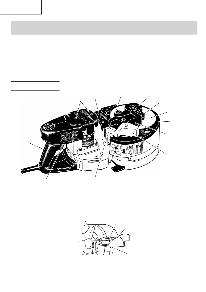
NAME OF PARTS
Center roller
Center plate
Turn table
Cam cover
Guide
Handle
Tail cover
Set screws
Allen key
Bending roller
Lever
Switch trigger
Cam cover
Hexagon socket bolt
Grip rubber
10
Grip rubber
Fig. 1
Cutter guard
Upper cutter
Lower cutter
Fig. 2
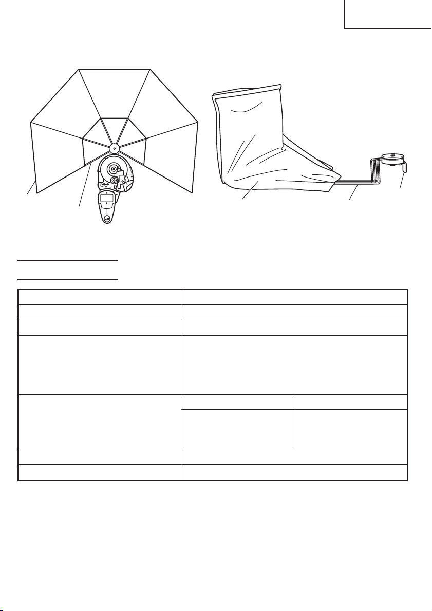
When installing the deflection When folding the deflection
guard guard
English
Guard
Arm
Fig. 3 Fig. 4
Guard
Arm
SPECIFICATIONS
Motor Single-Phase, Series Commutator Motor
Power Source Single-Phase, 120 V AC 60 Hz
Current 8 A
Capacities (1) Material: Concrete reinforcing bars only
(for ASTM)
GRADE 40, GRADE 60
(2) Bar Designation Size
#3, #4, #5 (3/8", 1/2", 5/8")
Cutting Bending
Number of piece(s) that
can be processed at one time
No-Load Speed 0 – 16/min.
Weight (without cord) 39.7 lbs (18.0 kg)
#3 (3/8")..... 2 pieces #3 (3/8") .... 3 pieces
#4 (1/2")..... 1 piece #4 (1/2") .... 2 pieces
#5 (5/8")..... 1 piece #5 (5/8") .... 1 piece
Base
11

English
ASSEMBLY AND OPERATION
APPLICATIONS
䡬 Cutting of rebar
䡬 Bending of rebar
PRIOR TO OPERATION
1. Power source
Ensure that the power source to be utilized conforms to the power source requirements
specified on the product nameplate.
2. Power switch
Ensure that the switch is in the OFF position. If the plug is connected to a receptacle while
the switch is in the ON position, the power tool will start operating immediately and can
cause serious injury.
3. Extension cord
When the work area is far away from the power source, use an extension cord of sufficient
thickness and rated capacity. The extension cord should be kept as short as practicable.
WARNING: Damaged cord must be replaced or repaired.
4. Check the receptacle
If the receptacle only loosely accepts the plug, the receptacle must be repaired. Contact
a licensed electrician to make appropriate repairs.
If such a fautly receptacle is used, it may cause overheating, resulting in a serious hazard.
5. Confirming condition of the environment:
Confirm that the work site is placed under appropriate conditions conforming to
prescribed precautions.
6. For safety sake, use the provided Allen key to make absolutely sure that the hexagon
socket bolt is securely clamped. Use of the unit with the bolt in a loosely clamped
condition can result in damage to the unit and cutter as well as accidents.
7. Confirm that the cutter is in sharp condition.
Make certain that the cutter is in a sharp condition. Continued use of a worn out and
deformed cutter with dull edges results in damage to the unit and cutter as well as
accidents.
12
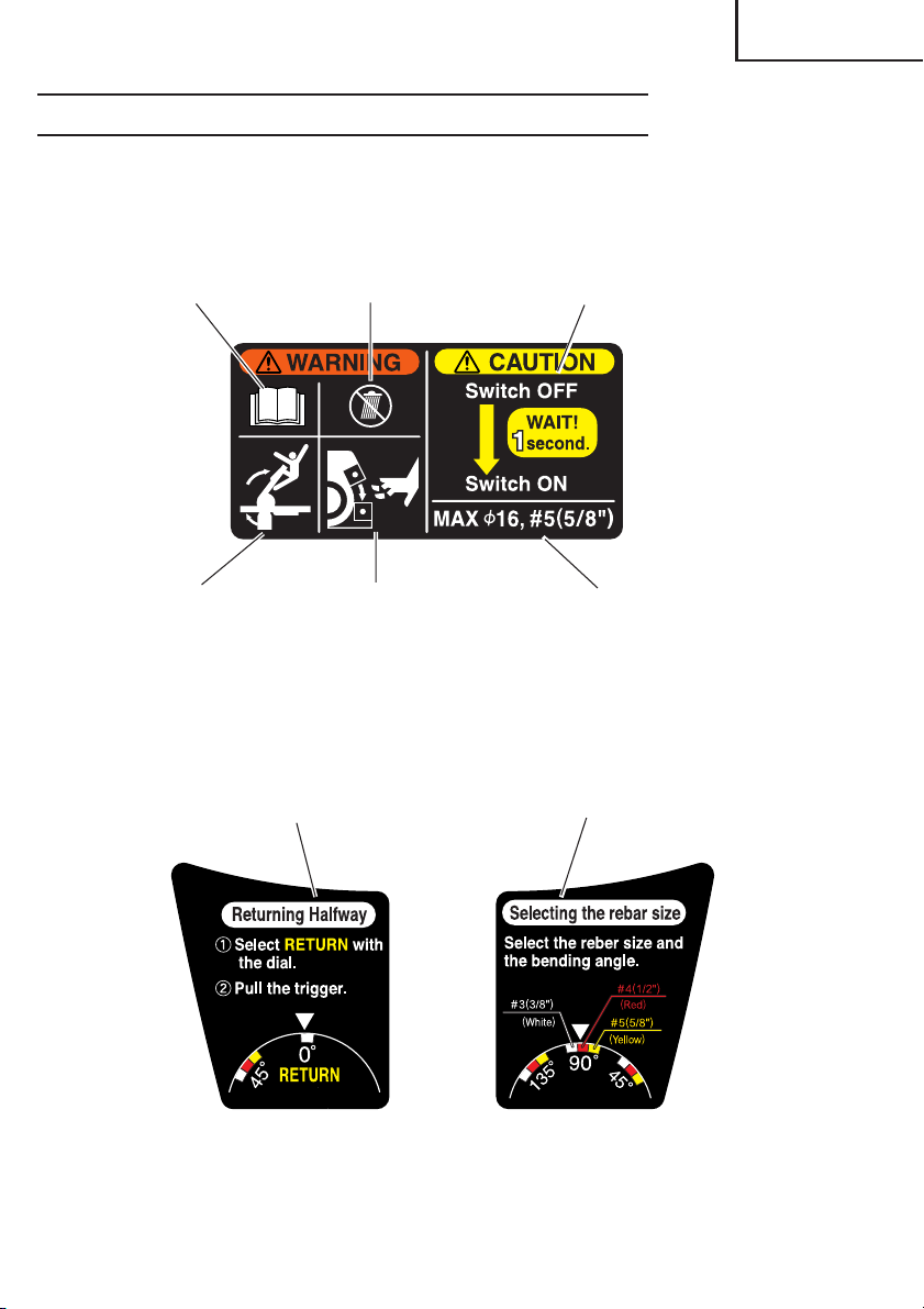
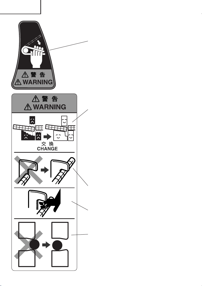
PICTGRAPH ILLUSTRATION AND EXPLANATION
If the switch is turned off and then
immediately turned on again, the
motor may not start. Wait for at least
Read handling
instructions before
use.
Do not this electric
power tools in wet
wether conditions.
one full second before attempting to
turn the motor on again after it has
been switched off.
English
Begin operation only after
ensuring that there are no
people within the turning
range of the material to
be bent.
(Returning Halfway)
1 Select RETURN with the dial.
2 Pull the triger.
Never bring your
hand close to the
cutter during
operation.
Avoid any work exceeding the
maximum capacities.
(Rebar diameter: #5 (5/8"))
(Selecting the rebar size)
Select the rebar size and
the bending angle.
13
English
● If you bend the rebar with a large angle while placing
your hand onto it, there is a fear of getting your
hand caught in by the fold-back reaction of the rebar.
Never place your hand onto the position where the
rebar may fold back.
● The cutter blade can get worn out by repeated rebar
cutting. Continued use of a worn-out cutter can
result in the damage and the broken pieces flying
around. Replace it with a new cutter after no more
than 5,000 times of cutting.
● The machine is so designed that the upper cutter
and the grip rubber can support a rebar.
If the grip rubber gets worn out, there is a fear that
it cannot sufficiently hold the rebar and gets broken
down with its parts flying around, etc.
If the grip rubber cannot hold the rebar much longer,
replace it with a new grip rubber. Also replace the
worn grip rubber with new one when replacing the
cutter.
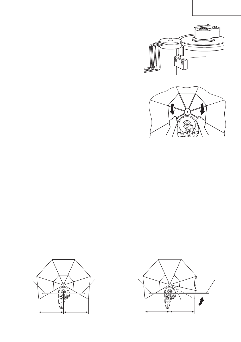
● During cutting work, securely hook the rebar to the
reaction stopper B. Furthermore, secure enough
length of a rebar to be hooked to the reaction
stopper B.
● Avoid bringing your hand near to the reaction
stopper B during operation. If you do so, you may
get your finger caught in or may run the hazard of
other injuries.
● Set the rebar in the center or the recess of the cutter
during cutting work. Any cutting work with the
rebar set on corners or ends of the cutter can result
in the pieces of broken rebar flying around or the
damage to the cutter and the machine.
14
English
HOW TO USE (CUTTING)
Reaction stopper B
Rebar
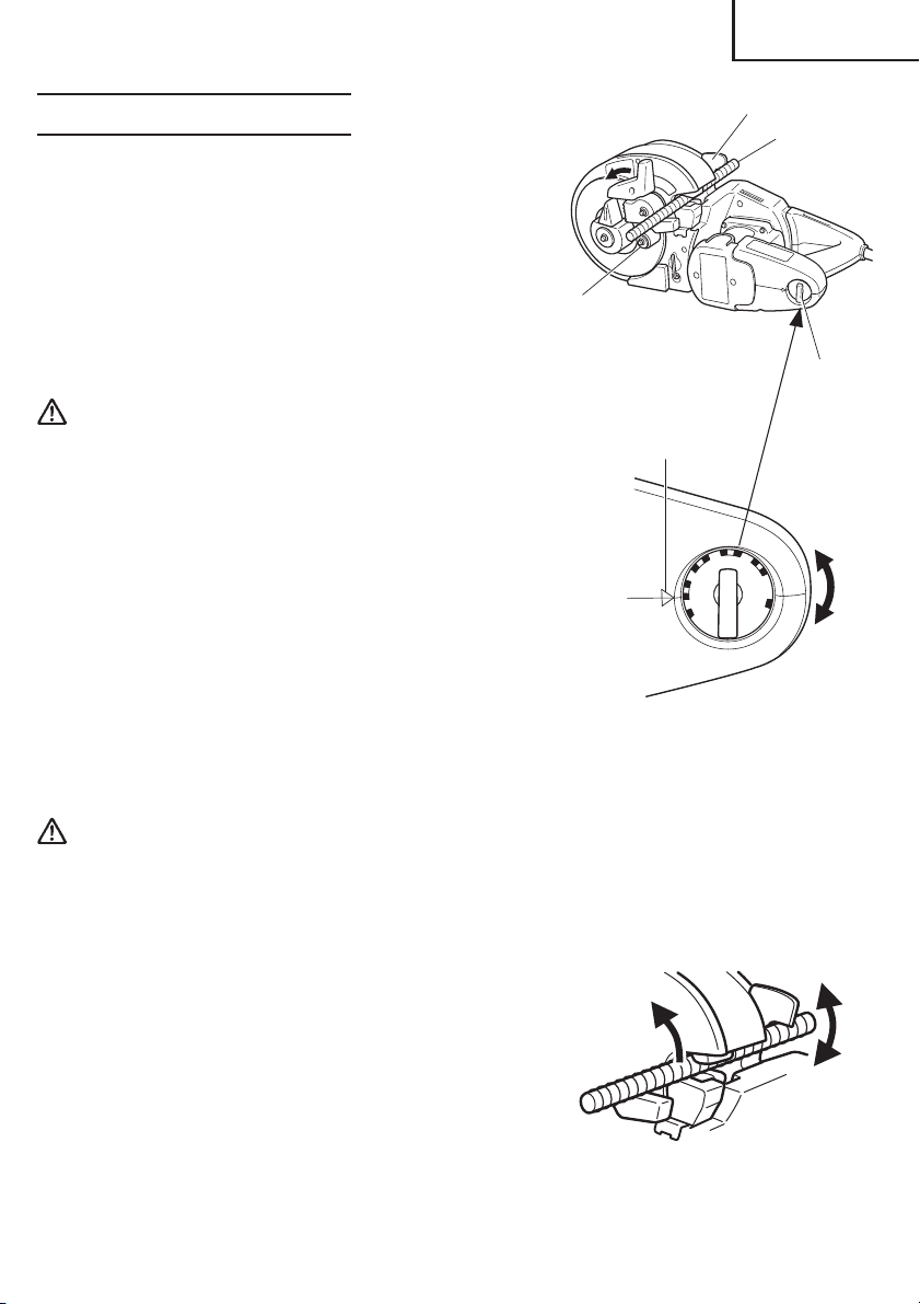
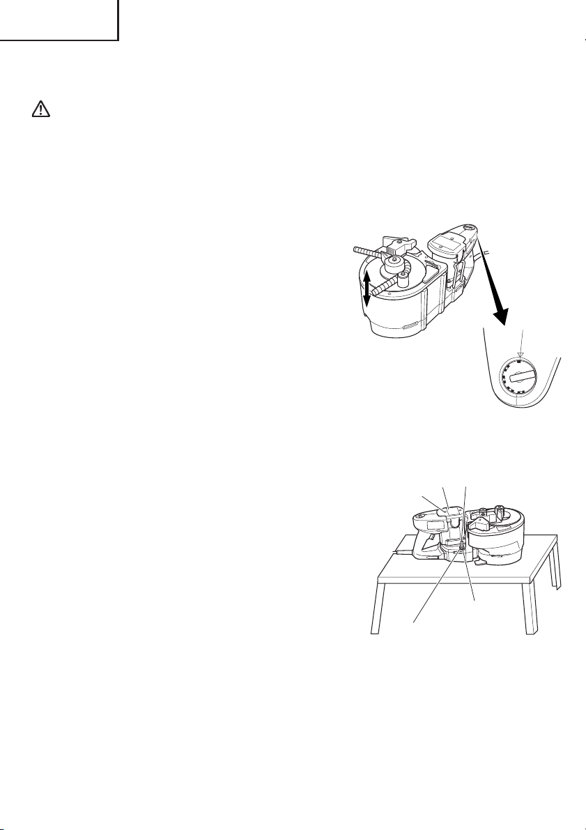
1. Normal cutting (Fig. 5)
(1) Turn the lever in the direction of the arrow mark
and open the cover.
(2) Set the setting dial at the “cut” position. (Turn
the setting dial all the way clockwise.) (Fig. 6)
(3) Set the unit in the position shown in Fig. 5.
(4) Set the rebar to be cut on the lower cutter.
(5) When the rebar is set, make sure that the reaction
Bending
roller
stopper B is hooked to the rebar.
(6) Pull the switch trigger and cut the rebar.
Fig. 5
Setting
dial
WARNING:
䡬 While turning switches, never put your hand close
to the cutter, reaction stopper, or bending roller.
䡬 Bringing your hand close to these components can
result in serious injury.
䡬 Do not cut any rebar exceeding the maximum
capacities of the unit described in the specifications.
䡬 Never cut any hard materials such as PC(Precast
concrete) steel. Materials of this type are likely to
scatter into pieces and cause injuries.
䡬 The rebar you are cutting may have a hard spot in
it. Quality may vary within each rebar. Do not
attempt to cut NON-GRADE rebar.
䡬 Replace the worn grip rubber with new one when
replacing the cutter.
䡬 Note that the unit is not a hand held tool. Be absolutely sure to use the unit only after
placing it on stable spots such as floor, ground, etc.
Adjusting position
135˚
180˚
CUT
Fig. 6
90˚
45˚
RETURN
0˚
CAUTION:
Even after the cutting has been completed, continue pulling the switch trigger until the
motor starts to run in the reverse direction and the cutter starts to return. If the switch
trigger is released too early, the cutter will not return and the trigger will have to be
pulled again.
2. Removing the rebar during cutting operation.
(Fig. 7)
If the switch trigger is released in the middle of
cutting, the cutter can come to a stop at a halfway
position, jumming the rebar in the unit.
When this occurs, you can either pull the switch
trigger again and cut off the rebar, or you can free
the rebar by bringing the upper cutter back up to
the home position by carrying out the following
procedure. (Fig. 7)
Fig. 7
15
English
0˚
RETURN
CUT
45˚
90
˚
135˚
180
˚
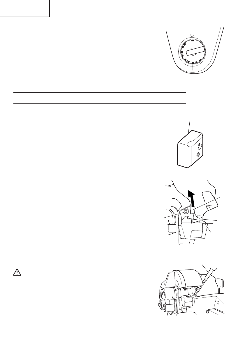
䡬 Removing (Fig. 8)
Set the setting dial to the “RETURN” position as
shown in Fig. 8 and pull the switch trigger again.
SERVICE LIFE AND REPLACEMENT OF THE CUTTER
Fig. 8
1. Service life of cutter (Fig. 9)
Repeated cutting of the rebar can result in the
"wear and tear", "deformation", "nicked edges",
etc. Using the cutter under such circumstances will
not only damage the machine but also there will be
a fear of the broken cutter fragments flying around.
Replace it with a new cutter after cutting no more
than 5,000 pieces of rebar.
2. Before removing the cutter
(1) Pull the switch lightly and let the upper cutter
move slowly. When the hexagon socket bolt
that fixes the upper cutter comes out of the cam
cover, turn the switch OFF and stop the motor.
(2) Unplug the power cord from the receptacle.
3. Removal
䡬 If you remove the hexagon socket bolt using the
provided Allen key, you can remove the cutter.
(Pushing the cutter guard up in the direction of
the arrow shown in Fig. 10, facilitates removal
of the upper cutter.)
䡬 Removal of the lower cutter can be easily made
if the lower cutter is wrenched with a Phillips
head screwdriver as shown in the following
diagram. (Fig. 11)
WARNING:
䡬 To prevent accidents, always be sure to turn the
switch OFF and unplug the power cord from the
receptacle.
䡬 If you remove the hexagon socket bolt using the
provided Allen key, you can remove the cutter.
(Pushing the cutter guard up in the direction of the
arrow shown in Fig. 10, facilitates removal of the
upper cutter.)
16
Hexagon
socket
bolt
Blade
Fig. 9
Cutter
guard
Upper
cutter
Lower
cutter
Fig. 10
Fig. 11
English
0˚
RETURN
CUT
45˚
90
˚
135˚
180˚
4. Mounting
(1) Get rid of dust around the cutter installing section and clean it up.
(2) Align the hole of a new cutter and the position of a pin, and insert into the installing
section.
(3) Also replace the hexagon socket bolt (packed along with the cutter) with a new one
simultaneously, completely tighten it using the attached Allen key, and then fix the
cutter.
CAUTION:
䡬 Install the cutter and accessories securely according to the instruction manual. If you fail
to install them properly, they may come off and cause an injury.
䡬 Be sure to unplug the power cord from the receptacle when the cutter is checked,
cleaned, and replaced. Failure to do so can result in a serious injury.
HOW TO USE (BENDING)
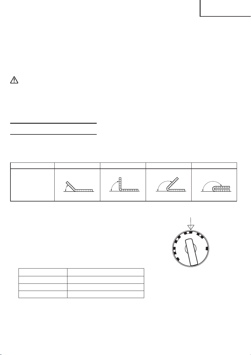
1. Setting bending angles by setting dial.
The bar can be bent according to the angles indicated on the setting dial, as shown in Fig.
12.
Dial indication 45° 90° 135° 180°
Condition of rebar
180°135°90°45°
Fig. 12
Adjusting position
In bending the rebar of #3(3/8"), #4(1/2"), and #5(5/
8") diameters, a difference takes place in the bending
angle even in the same dial position depending
upon the difference of rebar's thickness. Slightly
change a position of the setting dial depending
upon the rebar's diameter even with the same
bending angle as shown in Fig. 13.
Size of rebar Colors of indicated marks
Fig. 13
#3(3/8") White
#4(1/2") Red
#5(5/8") Yellow
NOTE
Even at the same dial setting position, the bending angle can sometimes differ if the diameter
or hardness of the rebar is different. Use the angle marks merely as a rough guideline.
17

English
2. Ordinary bending.
(1) Set the unit in the position with the turntable up
as shown in Fig. 14.
(2) Make sure that the cover is closed.
(3) Set the setting dial at the desired angle. (Fig. 13)
(4) Place the rebar on the center plate and set it
correctly as shown in Fig. 14.
(5) Pull the switch trigger and bent the rebar.
(6) Continue pulling the switch trigger untill the
motor makes reverse rotation and the bending
roller starts to return. (Once the bending roller
starts to return, it will automatically return all
the way to the home position even if the switch
trigger is released.)(Fig. 15)
Bending length
8" (200 mm) or
more
Fig. 14
Center plate
Bending
roller
Cover
WARNING:
䡬 Make absolutely sure that the cutter cover is closed
when you don’t carry out the cutting work. If the
cover is kept open, the cutter can jam on foreign
objects and cause serious accidents. (Fig. 16)
䡬 Never bring your hand close to the bending roller
during operation.
䡬 If you bend the rebar with a large angle while
placing your hand onto it, there is a fear of getting
your hand caught in by the fold-back reaction of
the rebar. Never place your hand onto the position
where the rebar may fold back.
䡬 Do not bend any rebar exceeding the maximum
capacities of the unit described in the specifications.
Never bend any hard materials such as PC(Precast
concrete) steel. Materials of this type are likely to
scatter into pieces and cause injuries.
䡬 The rebar you are bending may have a hard spot in
it. Quality may vary within each bar. Do not attempt
to bend NON-GRADE Rebar.
䡬 Never place your hand onto the bending side of the
rebar. If you do so, your hand may be caught in the
mechanical parts.
䡬 Install the deflection guard for operation with the bending length of a rebar 20" (inside
dimension of the deflection guard) or less to protect the persons around the rebar cutter/
bender in case rebar splinters into pieces and deflects during bending. (Fig. 20)
䡬 Remove the deflection guard when bending a rebar whose bending length and the fixed
length are more than 20" to prevent damage to the deflection guard.
䡬 Replace the deflection guard with new one if it is damaged. Damaged deflection guard
cannot protect the persons around the rebar cutter/bender in case a rebar splinters into
pieces and deflects during bending.
䡬 Note that the unit is not a hand-held tool. Be absolutely sure to use the unit only after
placing it on a stable spots such as floor, ground, etc.
18
Lever
Switch trigger
Fig. 15
Cover
Fig. 16
English
䡬 Begin operation only after marking sure that there
are no people within the turning range of the
material to be bent.
䡬 The minimum required bending length is 8" (200
mm).
If the bending length is not long enough, the rebar
can come off during bending operation, or it can
break into fragments and scatter dangerously.
(Fig. 14)
䡬 Be sure to set the rebar in the roller correctly. If it
protrudes from the roller, the rebar can come off
during bending operation and scatter into pieces.
䡬 Bend less than every 3 pieces of rebar with a #3(3/
8") diameter, less than every 2 pieces with a #4(1/
2") diameter, and every 1 piece with a #5(5/8")
diameter.
䡬 Remember that the cutter moves even during the
bending operation, thereby, close the cutter cover
without fail.
Fig. 17
Fig. 18
Slot for
base
insertion
3. How to install deflection guard
The deflection guard is provided to protect the persons around the rebar cutter/bender
in case a rebar splinters into pieces and deflects during bending. Install the deflection
guard to the VB16Y for operation with the bending length of a rebar 20" (inside dimension
of the deflection guard) or less.
(1) Insert the base of the deflection guard into the slot of the rebar cutter/bender. (Fig. 17)
(2) Open the guard fully by pulling the arms as shown below until a click is heard. (Fig.
18)
4. How to remove deflection guard
䡬 Reverse the installation procedure to remove the deflection guard.
5. How to use deflection guard
(1) Be sure to install the deflection guard when bending a rebar whose bending length
and the fixed length are 20" (inside dimensin of deflection guard) or less (Fig. 19)
(2) Be sure to install the deflection guard when bending a rebar whose bending length
is 20" (inside dimensin of diflection guard) or less and the fixed length is more than
20". In this case, move the arm at the fixed end. (Fig. 20)
Bending
side
Fixed
end
20"
Fig. 19 Fig. 20
20"
Bending
side
20" 20"
Fixed
end
Arm
19
English
0°
45°
90°
135
°
180°
R
E
T
U
R
N
C
U
T
(3) Remove the deflection guard when bending a rebar whose bending length and the
fixed length are more than 20" (inside dimension of the deflection guard).
CAUTION:
䡬 Set a rebar on the rebar cutter/bender so that the bending length is equal to or shorter
than the fixed length.
6. Bending by eye measurement.
Since the unit uses a variable-speed switch, you can bend the rebar to your desired angle
by eye measurement in addition to the dial setting.
(1) Set the setting dial to a larger angle than you
desire.
(2) Pull the switch trigger lightly and bend the rebar
slowly.
(3) When the rebar is bent to the desired angle,
stop pulling the switch. If the bar is still small of
the desired angle, pull the switch again.
(4) Remove the rebar after bending has been
finished. Then, pull the switch once more and
return the bending roller to the home position.
(Continue pulling the switch until the bending
roller begins reverse rotation.)
7. Removing rebar during bending operation
Fig. 21
When bending out at a low speed in “bending by
eye measurement”, the rebar can sometimes get
caught in the bending roller due to its own flexure.
If this occurs, you can return the bending roller to
the home position by pulling the switch again after
setting the setting dial to the “return” position.
Set
screws
Tail
cover
Bolt
This is the same method used to remove the rebar
when it gets caught during cutting operation. (Fig.
21)
8. Using hole to fix unit in place.
A hole is provided at the center of the unit to fix and
stabilize it. This hole comes in quite handy when
used in the following manner. (Fig. 22)
䡬 For bending operation when the unit is fixed to
a work bench.
This hole will prove very convenient when the
unit is bolted to a suitable work bench.
(Bolt size M10, less than W3/8.)
Nut
Hole to fix
unit
Fig. 22
20
English
MAINTENANCE AND INSPECTION
WARNING: Be sure to switch power OFF and disconnect the plug from the receptacle
during maintenance and inspection.
1. Inspecting the cutter
Continued use of a dull or damaged cutter will result in reduced cutting efficiency and
may cause overloading of the motor. Replace the cutter with a new one as soon as
excessive abrasion is noted.
2. Inspecting the mounting screws
Regularly inspect all mounting screws and ensure that they are properly tightened.
Should any of the screws be loosened, retighten them immediately.
WARNING: Using this Reber cutter/bender with loosened screws is extremely
dangerous.
3. Maintenance of the motor
The motor unit winding is the very “heart“ of the power tool. Exercise due care to ensure
the winding does noto become damaged and/or wet with oil or water.
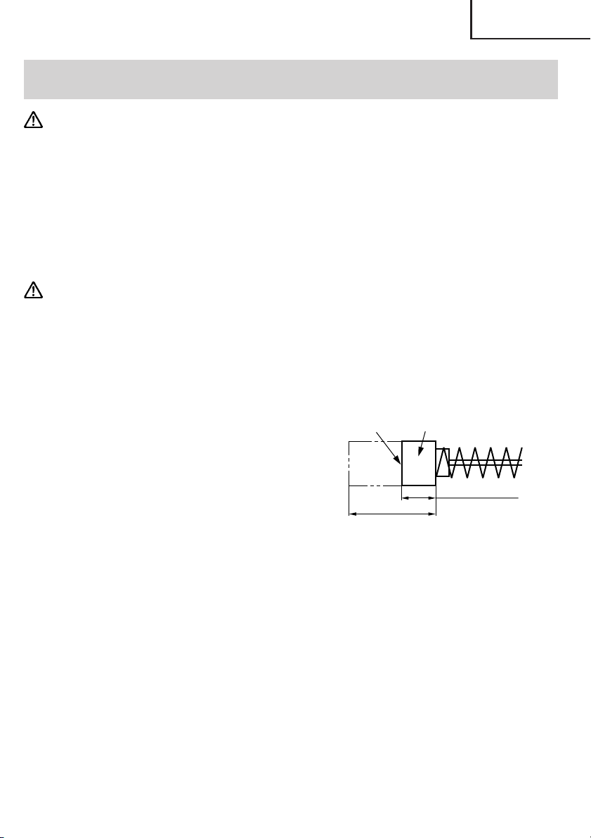
4. Inspecting the carbon brushes (Fig. 23)
The Motor employs carbon brushes which
are consumable parts. When they become
worn to or near the “wear limit”, it could
result in motor trouble. When an auto-stop
carbon brush is equipped, the motor will
stop automatically. At that time, replace
both carbon brushes with new ones which
have the same carbon brush Numbers shown
in the figure. In addition, always keep carbon
brushes clean and ensure that they slide
freely within the brush holders.
Wear limit
0.67” (17 mm)
No. of carbon
brush
43
0.24" (6 mm)
Fig. 23
NOTE: Use HITACHI carbon brush No. 43 indicated in Fig. 23.
5. Replacing carbon brushes
Loosen the set screws and remove the tail cover. Remove the brush caps and carbon
brushes. After replacing the carbon brushes, do not forget to tighten the brush caps
securely and to mount the tail cover with set screws.
6. Service and repairs
All quality power tools will eventually require servicing or replacement of parts because
of wear from normal use. To assure that only authorized replacement parts will be used,
all service and repairs must be performed by a HITACHI AUTHORIZED SERVICE CENTER,
ONLY.
21

English
ACCESSORIES
WARNING: Accessories for this power tool are mentioned in this Instruction Manual.
The use of any other attachment or accessory can be dangerous and
could cause injury or mechanical damage.
NOTE:
Accessories are subject to change without any obligation on the part of the HITACHI.
STANDARD ACCESSORIES
(1) Allen wrench (For M5 hexagon socket bolt) ....................................... 1 (attached to unit)
(2) One set of cutters .................................................................................. 1 (attached to unit)
(3) Deflection guard .................................................................................... 1
OPTIONAL ACCESSORIES.......sold separately
䡬 Cutter (Fig. 24)(Code No. 319706)
* One set containing two pieces
Fig. 24
NOTE:
Specifications are subject to change without any obligation on the part of the HITACHI.
22

Français
INFORMATIONS IMPORTANTES
Lire et comprendre toutes les instructions de fonctionnement, les précautions de sécurité et
les avertissements dans ce mode d’emploi avant d’utiliser ou d’entretenir cet outil motorisé.
La plupart des accidents causés lors de l’utilisation ou de l’entretien de l’outil motorisé
proviennent d’un non respect des règles ou précautions de base de sécurité. Un accident
peut la plupart du temps être évité si l’on reconnaît une situation de danger potentiel avant
qu’elle ne se produise, et en observant les procédures de sécurité appropriées.
Les précautions de base de sécurité sont mises en évidence dans la section “SECURITE” de
ce mode d’emploi et dans les sections qui contiennent les instructions de fonctionnement
et d’entretien.
Les dangers qui doivent être évités pour prévenir des blessures corporelles ou un
endommagement de la machine sont identifiés par AVERTISSEMENTS sur l’outil motorisé
et dans ce mode d’emploi.
Ne jamais utiliser cet outil motorisé d’une manière qui n’est pas spécifiquement recommandée
par HITACHI sans avoir d’abord vérifié que l’utilisation prévue est sans danger pour vous et
les autres.
SIGNIFICATION DES MOTS D’AVERTISSEMENT
AVERTISSEMENT indique des situations potentiellement dangereuses qui, si elles sont
ignorées, pourraient entraîner de sérieuses blessures personnelles.
PRECAUTION indique des situations dangereuses qui, si elles sont ignorées, pourrait
entraîner de légères blessures personnelles ou endommager la machine.
REMARQUE met en relief des informations essentielles.
23

Français
SECURITE
CONSIGNES DE SECURITE RELATIVES AUX OUTILS ELECTRIQUES.
LIRE TOUS LES AVERTISSEMENTS ET TOUTES LES INSTRUCTIONS D’UTILISATION DU
MANUEL AVANT DE METTRE L’OUTIL EN SERVICE OU DE L’ENTRETENIR :
AVERTISSEMENT: Lorsqu’on utilise l’outil électrique, prendre toutes les
précautions nécessaires pour éviter au maximum tout risque
de choc électrique ou autre blessure physique.
En particulier, toujours respecter les consignes de sécurité
suivantes :
1. TOUJOURS LAISSER LES PROTECTIONS EN PLACE ET LES MAINTENIR EN BON ORDRE
DE MARCHE.
2. TOUJOURS RETIRER LES CLAVETTES DE REGLAGE ET LES CLES AVANT DE METTRE
L’OUTIL EN MARCHE. Toujours vérifier que les clés et les clavettes de réglage sont bien
toutes retirées de l’outil avant de le mettre en marche.
3. TOUJOURS MAINTENIR L’AIRE DE TRAVAIL PROPRE. Pour éviter tout risque de
blessure, ne pas encombrer l’aire de travail ni l’établi.
4. NE JAMAIS UTILISER L’OUTIL DANS UN ENVIRONNEMENT DANGEREUX. Ne jamais
utiliser l’outil électrique dans un endroit humide ou mouillé, et ne jamais l’exposer à la
pluie. Toujours veiller à ce que l’aire de travail soit suffisamment éclairée.
5. NE JAMAIS LAISSER LES ENFANTS NI AUCUNE AUTRE PERSONNE APPROCHER DE
L’AIRE DE TRAVAIL. Interdire l’accès de l’aire de travail à tout le monde (en particulier aux
enfants). Toujours débrancher l’outil quand on s’en éloigne et veiller à ce que personne
ne puisse pénétrer dans l’aire de travail en mettant des verrous aux portes et aux
interrupteurs principaux. Toujours retirer le bouton de déverrouillage de l’outil et le
ranger en lieu sûr lorsqu’on ne s’en sert pas.
6. NE JAMAIS FORCER L’OUTIL. Il effectuera le travail le meilleur et avec la sécurité
maximale au régime pour lequel il a été conçu.
7. TOUJOURS UTILISER LES OUTILS APPROPRIES. Ne jamais utiliser un outil ou un
accessoire pour un travail pour lequel il n’est pas conçu.
8. PORTER DES VETEMENTS APPROPRIES PENDANT LE TRAVAIL. Ne jamais porter de
vêtements lâches ni de gants, cravate, bagues, bracelets ni aucun autre bijou. Ils
pourraient se coincer dans les pièces en rotation. Toujours porter des chaussures antidérapantes, en particulier avec des doigts de pied en acier. Porter un couvre-chef qui
recouvre les cheveux longs.
9. TOUJOURS PORTER DES LUNETTES DE PROTECTION PENDANT LE TRAVAIL POUR
EVITER TOUT RISQUE DE BLESSURE DES YEUX. Les lunettes ordinaires n’assurent pas
une protection suffisante parce que les verres ne sont pas faits en verre de sécurité. Par
ailleurs, porter un masque sur le visage pour accroître la sécurité, et un masque antipoussière si le travail doit dégager de la poussière.
10. TOUJOURS FIXER LA PIECE A LA GARDE OU A LA TABLE. Utiliser des dispositifs de
serrage ou un étau pour tenir la pièce. Cela sera plus sûr que de tenir la pièce à la main
et libérera les deux mains pour le travail.
24

Français
11. NE JAMAIS TROP SE PENCHER. Toujours garder une bonne assise et un bon équilibre
pendant le travail.
12. TOUJOURS ENTRETENIR LES OUTILS AVEC SOIN. Maintenir les outils aiguisés et
propres pour optimiser le travail et la sécurité. Toujours suivre les instructions de
graissage et de remplacement des accessoires.
13. TOUJOURS DEBRANCHER L’OUTIL avant un entretien et lors du remplacement des
lames ou de tout autre accessoire.
14. NE JAMAIS RISQUER UNE MISE EN MARCHE INOPINEE LORSQU’ON BRANCHE
L’OUTIL. Toujours vérifier que l’interrupteur est en position OFF avant de brancher la
fiche d’alimentation dans la prise secteur.
15. TOUJOURS UTILISER EXCLUSIVEMENT LES ACCESSOIRES RECOMMANDES POUR
L’OUTIL. Consulter le mode d’emploi pour la description des outils recommandés. Pour
éviter tout risque de blessure, utiliser exclusivement les accessoires recommandés pour
cet outil.
16. Ne jamais monter sur l’outil. Pour éviter tout risque de blessures graves, ne pas incliner
l’outil, et veiller à ne pas toucher le couteau par inadvertance.
17. TOUJOURS VERIFIER SI L’OUTIL A DES PIECES ENDOMMAGEES AVANT DE L’UTILISER.
Toujours vérifier si la protection et les autres composants sont endommagés avant
d’utiliser l’outil pour s’assurer qu’ils fonctionneront correctement. Vérifier si toutes les
pièces mobiles sont bien alignées, non voilées, ou toute autre condition qui pourrait
entraver leur bon fonctionnement. Toujours réparer ou remplacer les protections ou les
autres pièces endommagées avant d’utiliser l’outil.
18. TOUJOURS VERIFIER LE SENS DE ROTATION DE LA LAME AVANT D’UTILISER L’OUTIL.
Toujours avancer la pièce dans l’outil contre le sens de déplacement du couteau pour
éviter tout risque de blessure.
19. NE JAMAIS S’ELOIGNER DE L’OUTIL QUAND IL FONCTIONNE. LE METTRE HORS
TENSION. Ne pas s’éloigner de l’outil tant qu’il n’est pas complètement arrêté. Toujours
mettre l’outil hors tension quand on ne s’en sert pas. Toujours débrancher le cordon
d’alimentation quand on ne se sert pas de l’outil.
20. L’outil n’est pas conçu pour des applications de fabrication en série, et il ne devra donc
pas être utilisé dans un environnement de fabrication en série.
21. Pour les réparations, utiliser exclusivement des pièces de rechange agréées.
22. Alimenter l’outil exclusivement sur un courant alternatif de 120 volts. Une tension ou une
alimentation incorrectes pourraient provoquer un mauvais fonctionnement de l’OUTIL
ELECTRIQUE et provoquer des blessures physiques ou des dommages matériels graves.
23. FICHES POLARISEES Pour réduire tout risque de choc électrique, l’appareil possède une
fiche polarisée (l’une des lames est plus large que l’autre). Cette fiche ne rentrera dans
une prise polarisée que dans un sens. Si la fiche ne rentre pas dans la prise, l’inverser.
Si elle ne rentre toujours pas, faire installer une prise appropriée par un électricien
qualifié. Ne pas modifier la fiche de quelque façon que ce soit.
25

Français
REGLES DE SECURITE SPECIFIQUES ET SYMBOLES
AVERTISSEMENT: A des fins de sécurité, lire le mode d’emploi avant d’utiliser
l’outil.
Porter des lunettes de protection.
Risque de blessure en cas de démarrage accidentel.
Ne pas utiliser dans un atelier domestique ni dans aucune
autre aire de travail où des enfants risquent de se trouver
présents.
1. Tenir les outils par les surfaces de grippage lors de la réalisation d’opération où l’outil
de coupe risque d’entrer en contact avec des câbles cachés ou son propre cordon. Un
contact avec un fil “sous tension” mettra les parties métalliques de l’outil “sous tension”
et électrocutera l’utilisateur.
2. TOUJOURS porter des bouchons d’oreille lors de l’utilisation de l’outil pendant de
longues périodes. Une exposition prolongée à un son de forte intensité peut endommager
l’ouïe de l’utilisateur.
3. Ne jamais toucher les parties mobiles.
Ne jamais placer ses mains, ses doigts ou toute autre partie de son corps près des parties
mobiles de l’outil.
4. Ne jamais utiliser un outil motorisé pour des applications autres que celles spécifiées.
Ne jamais utiliser un outil motorisé pour des applications autres que celles spécifiées
dans le mode d’emploi.
5. Manipuler l’outil correctement
Utiliser l’outil de la façon indiquée dans ce mode d’emploi. Ne pas laisser tomber ou
lancer l’outil. Ne jamais permettre que l’outil soit utilisé par des enfants, des personnes
non familiarisées avec son fonctionnement ou un personnel non autorisé.
6. Maintenir toutes les vis, tous les boulons et les couvercles fermement en place.
Maintenir toutes les vis, tous les boulons et les couvercles fermement montés. Vérifier
leurs conditions périodiquement.
7. Ne pas utiliser les outils motorisés si le revêtement de plastique ou la poignée est fendu.
Des fentes dans le revêtement ou la poignée peuvent entraîner une électrocution. De tels
outils ne doivent pas être utilisés avant d’être réparé.
8. Les couteaux et les accessoires doivent être fermement montés sur l’outil.
Eviter les blessures potentielles personnelles et aux autres. Les couteaux, les instruments
de coupe et les accessoires qui ont été montés sur l’outil doivent être fixés et serrés
fermement.
9. Garder propres les évents d’air du moteur
Les évents d’air du moteur doivent être maintenus propres de façon que l’air puisse
circuler librement tout le temps. Vérifier les accumulations de poussière fréquemment.
10. Utiliser l’outil motorisé à la tension nominale.
Utiliser l’outil motorisé à la tension spécifiée sur sa plaque signalétique.
Si l’on utilise l’outil motorisé avec une tension supérieure à la tension nominale, il en
résultera une rotation anormalement trop rapide du moteur et cela risque d’endommager
l’outil et le moteur risque de griller.
26

Français
11. Ne jamais utiliser un outil défectueux ou qui fonctionne anormalement.
Si l’outil n’a pas l’air de fonctionner normalement, fait des bruits étranges ou sans cela
paraît défectueux, arrêter de l’utiliser immédiatement et le faire réparer par un centre de
service Hitachi autorisé.
12. Ne jamais laisser fonctionner l’outil sans surveillance. Le mettre hors tension.
Ne pas abandonner l’outil avant qu’il ne soit complètement arrêté.
13. Manipuler l’outil motorisé avec précaution.
Si un outil motorisé tombe ou frappe un matériau dur accidentellement, il risque d’être
déformé, fendu ou endommagé.
14. Ne pas essuyer les parties en plastique avec du solvant.
Les solvants comme l’essence, les diluants, la benzine, le tétrachlorure de carbone et
l’alcool peuvent endommager et fissurer les parties en plastique. Ne pas les essuyer avec
de tels solvants.
Essuyer les parties en plastique avec un chiffon doux légèrement imbibé d’une solution
d’eau savonneuse et sécher minutieusement.
15. Définitions pour les symboles utilisés sur cet outil
V ............. volts
Hz ........... hertz
A ............. ampères
no .......... vitesse sans charge
W ............ watt
............ Construction de classe II
---/min .... tours par minute
PIECES DE RECHANGE
Pour les réparations, utiliser exclusivement des pièces de rechange identiques.
Les réparations devront être effectuées exclusivement par un centre de service après-vente
Hitachi agréé.
27

Français
UTILISER LE CORDON DE RALLONGE APPROPRIÉ
Utiliser exclusivement un cordon de rallonge en bon état. Lorsqu’on utilise un cordon de
rallonge, veiller à ce qu’il soit suffisamment lourd pour supporter le courant dont l’appareil
aura besoin. Un cordon trop petit provoquera une chute de la tension de ligne, ce qui
entraînera une perte de puissance et une surchauffe. Le tableau indique le calibre à utiliser
en fonction de la longueur du cordon et de l’intensité nominale indiquée sur la plaque
signalétique. En cas de doute, utiliser un calibre supérieur. Plus le numéro du calibre est petit,
plus le cordon est lourd.
CALIBRE MINIMUM DES CORDONS
Longueur totale de cordon en pieds (mètres)
0 – 25 26 – 50 51 – 100 101 – 150
(0 – 7,6) (7,9 – 15,2) (15,5 – 30,5) (30,8 – 45,7)
Intensité nominale CALIBRE
Supérieure Non supérieure
àà
0 – 618161614
6 – 10 18 16 14 12
10 – 12 16 16 14 12
12 – 16 14 12 Non recommandé
AVERTISSEMENT: Eviter tout risque de choc électrique. Ne jamais utiliser l’outil
avec un cordon électrique ou un cordon de rallonge
endommagé ou dénudé.
Inspecter régulièrement les cordons électriques. Ne jamais
utiliser dans l’eau ou à proximité d’eau, ni dans un
environnement susceptible de provoquer un choc électrique.
28

Français
DOUBLE ISOLATION POUR UN FONCTIONNEMENT PLUS SUR
Pour assurer un fonctionnement plus sûr de cet outil motorisé, HITACHI a adopté une
conception à double insolation. “Double isolation” signifie que deux systèmes d’isolation
physiquement séparés ont été utilisés pour isoler les matériaux conducteurs d’électricité
connectés à l’outil motorisé à partir du cadre extérieur manipulé par l’utilisateur. C’est
pourquoi, le symbole “ ” ou les mots “Double insulation” (double isolation) apparaissent
sur l’outil motorisé ou sur la plaque signalétique.
Bien que ce système n’ait pas de mise à terre extérieure, il est quand même nécessaire de
suivre les précautions de sécurité électrique données dans ce mode d’emploi, y-compris de
ne pas utiliser l’outil motorisé dans un environnement humide.
Pour garder le système de double isolation effectif, suivre ces précautions:
䡬 Seuls les CENTRES DE SERVICE AUTORISES HITACHI peuvent démonter et remonter cet
outil motorisé et uniquement des pièces de rechange HITACHI garanties d’origine
doivent être utilisées.
䡬 Nettoyer l’extérieur de l’outil motorisé uniquement avec un chiffon doux légèrement
imbibé d’une solution savonneuse et essuyer minutieusement.
Ne jamais utiliser des solvants, de l’essence ou des diluants sur les parties en plastique;
sinon le plastique risquerait de se dissoudre.
CONSERVER CES INSTRUCTIONS
ET
LES METTRE A LA DISPOSITION
DES AUTRES UTILISATEURS
DE CET OUTIL!
29

Français
DESCRIPTION FONCTIONNELLE
REMARQUE:
Les informations contenues dans ce mode d’emploi sont conçues pour assister l’utilisateur
dans une utilisation sans danger et un entretien de l’outil motorisé.
Certaines illustrations dans ce mode d’emploi peuvent montrer des détails ou des
accessoires différents de ceux de l’outil motorisé utilisé.
NOM DES PARTIES
Vis de fixation
Couvercle arrière
Poignée
Gâchette
Carter de came
Rouleau de
Clé Allen
Caoutchouc de poignée
Fig. 1
Protection du couteau
cintrage
Couteau supérieur
Rouleau central
Plaque centrale
Table rotative
Carter de
came
Guide
Levier
Boulon à douille
hexagonale
Caoutchouc de poignée
30
Couteau inférieur
Fig. 2

Installation de la protection Repliage de la protection
anti-fièche anti-fièche
Français
Protection
Bras
Fig. 3 Fig. 4
Protection
Bras
SPECIFICATIONS
Moteur Moteur série monophasé à collecteur
Source d’alimentation Secteur, 120 V 60 Hz, monophasé
Courant 8 A
Capacités (1) Matériel: Barres de renfort de béton seulement)
(pour ASTM)
GRADE 40, GRADE 60
(2) Taille de désignation des barres
#3, #4, #5 (3/8", 1/2", 5/8")
Coupe Cintrage
Nombre de piéces qu’il est
possible de traiter à la fois
Vitesse sans charge 0 – 16/min.
Poids (sans cordon) 39,7 lbs (18,0 kg)
#3 (3/8") ..... 2 pièces #3 (3/8") ..... 3 pièces
#4 (1/2") ..... 1 pièce #4 (1/2") ..... 2 pièces
#5 (5/8") ..... 1 pièce #5 (5/8") ..... 1 pièce
Base
31

Français
ASSEMBLAGE ET FONCTIONNEMENT
APPLICATIONS
䡬 Coupe de barres béton
䡬 Cintrage de barres béton
AVANT L’UTILISATION
1. Source d’alimentation
S’assurer que la source d’alimentation qui doit être utilisée est conforme à la source
d’alimentation requise spécifiée sur la plaque signalétique du produit.
2. Interrupteur d’alimentation
S’assurer que l’interrupteur est sur la position OFF (arrêt). Si la fiche est connectée sur
une prise alors que l’interrupteur est sur la position ON (marche), l’outil motorisé
démarrera immédiatement risquant de causer de sérieuses blessures.
3. Cordon prolongateur
Quand la zone de travail est éloignée de la source d’alimentation, utiliser un cordon
prolongateur d’épaisseur et de capacité nominale suffisante. Le cordon prolongateur
doit être aussi court que possible.
AVERTISSEMENT: Tout cordon endommagé devra être remplacé ou réparé.
4. Vérifier la prise
Si la prise reçoit la fiche avec beaucoup de jeu, elle doit être réparée. Contacter un
électricien licencié pour réaliser les réparations nécessaires.
Si une telle prise défectueuse est utilisée, elle peut causer une surchauffe entraînant des
dangers sérieux.
5. Vérification des conditions d’environnement
Vérifier que l’état de l’aire de travail est conforme aux précautions.
6. A des fins de sécurité, utiliser la clé Allen fournie pour être absolument sûr que le boulon
à douille hexagonale est solidement vissé. Le fait d’utiliser l’outil avec un boulon lâche
risque d’endommager l’outil et de provoquer des accidents.
7. Vérifier que le couteau est bien affûté.
S’assurer que le couteau est bien affûté. Le fait de continuer à utiliser l’outil avec un
couteau émoussé et déformé risque d’endommager l’outil et le couteau et de provoquer
des accidents.
32

SCHÉMA ET EXPLICATION
Lire le mode
d’emploi avant
d’utiliser l’outil.
Ne pas utiliser cet outil
électrique par temps
humide.
Français
Si l’on coupe l’interrupteur puis
qu’on le rallume tout de suite après,
le moteur risque de ne pas démarrer.
Attendre au moins une bonne
seconde avant de remettre le moteur
en marche après l’avoir éteint.
Ne pas utiliser l’outil sans
s’être auparavant assuré
qu’il n’y a personne dans
le rayon de rotation du
matériau à cintrer.
(Retour à mi-course)
1 Sélectionner RETURN avec la bague.
2 Tirer sur la gâchette.
Ne jamais approcher
les mains du
couteau pendant le
fonctionnement.
Eviter tout travail dépassant les
capacités maximales.
(Barre béton de #5 (5/8") de
diamètre)
(Sélection de la taille de la barre béton)
Sélectionner la taille de la barre béton et
l’angle de cintrage.
33

Français
● Si l’on cintre la barre béton à un angle large en
plaçant la main dessus, l’on risque de se prendre la
main lors de la réaction de retour de la barre béton.
Ne jamais mettre la main à l’endroit où la barre
béton risque de se plier en retour.
● Le couteau peut s’user après des coupes répétées
de barres béton. Le fait de continuer à utiliser un
couteau émoussé risque d’entraîner des dommages
et de faire voler des éclats. Remplacer le couteau
par un neuf au bout de 5 000 coupes.
● L’outil est conçu de façon que le couteau
supérieur et le caoutchouc de la poignée puissent
supporter une barre béton.
Si le caoutchouc de la poignée s’use, il risque de
ne pas assurer une prise suffisante de la barre
béton et de se briser en faisant voler des éclats,
etc.
Si le caoutchouc de la poignée ne supportera
bientôt plus la barre béton, le remplacer par un
neuf. Remplacer également le caoutchouc de la
poignée usé par un neuf lors du remplacement
du couteau.
● Pendant la coupe, accrocher solidement la barre
béton à la butée de réaction B. De plus, accrocher
une longueur suffisante de barre béton à la butée
de réaction B.
● Ne pas approcher les mains de la butée de réaction
B pendant le fonctionnement. L’on risque de se
prendre les doigts ou de recevoir des blessures.
● Placer la barre béton au centre ou dans le
renfoncement du couteau pendant la coupe. Une
coupe avec la barre béton placée sur les coins ou à
l’extrémité du couteau risque de faire voler les
morceaux de la barre béton cassée ou
d’endommager le couteau et l’outil.
34

Français
UTILISATION (COUPE)
Butée de réaction B
Barre béton
1. Coupe normale (Fig. 5)
(1) Tourner le levier dans le sens de la flèche et
ouvrir le couvercle.
(2) Mettre la bague de réglage sur la position
“coupe”. (Tourner la bague de réglage à fond
dans le sens des aiguilles d’une montre.) (Fig. 6)
(3) Mettre l’outil dans la position indiquée à la Fig.
5.
(4) Placer la barre béton à couper sur le couteau
inférieur.
(5) Lorsque la barre béton est installée, s’assurer
que la butée de réaction B est accrochée sur la
barre béton.
(6) Tirer sur la gâchette et couper la barre béton.
Rouleau
de cintrage
Bague de
réglage
Fig. 5
Position de réglage
AVERTISSEMENT:
䡬 Lors de l’action des interrupteurs, ne jamais
approcher les mains du couteau, de la butée de
réaction ni du rouleau de cintrage.
䡬 L’on pourrait se blesser grièvement.
䡬 Eviter tout travail de coupe dépassant les capacités
maximales de l’outil données dans les
spécifications.
䡬 Ne jamais couper de matériaux durs, par exemple
du béton préfabriqué (PC) ou de l’acier. Ce genre de
matériaux risque de se fendre en éclats et de
provoquer des blessures.
䡬 La barre béton que l’on est en train de couper peur
avoir un point dur. La qualité peut varier dans
chaque barre béton.
䡬 Ne pas tenter de couper une barre béton NON-GRADE.
䡬 Remplacer également le caoutchouc de la poignée usé par un neuf lors du remplacement
du couteau.
䡬 Noter que l’outil n’est pas un outil qui se tient dans la main. Il faudra absolument le poser
à un endroit stable, par exemple le plancher, le sol, etc.
Fig. 6
135˚
180˚
CUT
90˚
45˚
RETURN
0˚
PRECAUTION:
Lorsque la coupe est terminée, continuer à tirer sur la gâchette jusqu’à ce que le moteur
commence à tourner en sens inverse et que le couteau commence à revenir. Si l’on
relâche la gâchette trop tôt, le couteau risque de ne pas revenir et il faudra à nouveau
tirer sur la gâchette.
2. Retrait de la barre béton pendant la coupe
(Fig. 7)
Si l’on relâche la gâchette au milieu de la coupe, le
couteau risque de s’arrêter à mi-chemin, et la barre
béton restera coincée dans l’outil.
Dans ce cas, on pourra soit tirer à nouveau sur la
gâchette et terminer la coupe de la barre béton, soit
libérer la barre béton en ramenant le couteau
supérieur à la position d’origine en procédant
comme suit. (Fig. 7)
Fig. 7
35

Français
0˚
RETURN
CUT
45˚
90
˚
135˚
180
˚
䡬 Retrait (Fig. 8)
Mettre la bague de réglage sur la position
“RETURN”, comme indiqué à la Fig. 8, et tirer à
nouveau sur la gâchette.
DURÉE DE SERVICE ET
REMPLACEMENT DU COUTEAU
1. Durée de service du couteau (Fig. 9)
Des coupes répétées finiront inévitablement par
user la lame du couteau et par déformer et fissurer
les tranchants, etc. Si l’on continue à utiliser le
couteau alors qu’il est abîmé de cette façon, non
seulement cela risque d’endommager l’outil, mais
des éclats de matériau risquent également de
s’éparpiller. Remplacer le couteau par un neuf au
bout de 5 000 coupes.
2. Avant de retirer le couteau
(1) Tirer légèrement sur l’interrupteur de façon que
le couteau supérieur se déplace lentement.
Lorsque le boulon à douille hexagonale qui fixe
le couteau supérieur sort du couvercle de came,
couper l’interrupteur et arrêter le moteur.
(2) Débrancher le cordon d’alimentation de la prise.
3. Retrait
䡬 Si l’on retire le boulon à douille hexagonale
avec une clé Allen, le couteau sortira. (Pousser
la protection du couteau vers le haut dans le
sens la flèche de la Fig. 10 pour faciliter le retrait
du couteau supérieur.)
䡬 Le retrait du couteau inférieur s’effectuera en
toute facilité en le serrant avec un tournevis à
tête Phillips, comme indiqué sur le schéma
suivant. (Fig. 11)
Boulon à
douille
hexagonale
Fig. 8
Lame
Fig. 9
Protection
du
couteau
Couteau
supérieur
Couteau
inférieur
Fig. 10
AVERTISSEMENT:
䡬 Pour éviter tout risque d’accident, toujours éteindre
l’interrupteur (OFF) et débrancher le cordon
d’alimentation de la prise secteur.
䡬 Si l’on retire le boulon à douille hexagonale à l’aide
de la clé Allen, on pourra retirer le couteau. (Pousser
la protection du couteau dans le sens de la flèche,
comme indiqué à la Fig. 10, pour faciliter le retrait
du couteau supérieur.)
36
Fig. 11

Français
0˚
RETURN
CUT
45˚
90
˚
135˚
180˚
4. Montage
(1) Retirer toute poussière qui s’est accumulée autour de la section d’installation du
couteau et nettoyer.
(2) Aligner l’orifice du nouveau couteau sur l’emplacement de la tige, et insérer dans la
section d’installation.
(3) Remplacer également le boulon à douille hexagonale (fourni avec le couteau) par un
neuf au même moment, le serrer à fond avec la clé Allen, puis fixer le couteau.
PRECAUTION :
䡬 Installer solidement le couteau et les accessoires, en suivant les instructions du mode
d’emploi. Si on ne les installe pas correctement, ils risquent de se détacher et de
provoquer des blessures.
䡬 Bien débrancher le cordon d’alimentation de la prise secteur lors de la vérification, du
nettoyage et du remplacement du couteau. Sinon, l’on risque de se blesser grièvement.
UTILISATION (CINTRAGE)
1. Réglage des angles de cintrage avec la bague de réglage
La barre béton pourra être cintrée aux angles indiqués sur la bague de réglage, comme
indiqué à la Fig. 12.
Indication de
la bague
Position de la
barre béton
45° 90° 135° 180°
180°135°90°45°
Fig. 12
Lors du cintrage de barres béton de #3 (3/8"), #4 (1/
Position de réglage
2") ou #5 (5/8") de diamètre, il y aura une différence
dans l’angle de cintrage même si la bague est à la
même position à cause de la différence d’épaisseur
des barres béton. Modifier légèrement la position
de la bague de réglage en fonction du diamètre de
la barre béton, même si l’angle de cintrage est le
même, comme indiqué à la Fig. 13.
Taille de barre béton Couleur des repères indiqués
#3(3/8") Blanc
Fig. 13
#4(1/2") Rouge
#5(5/8") Jaune
REMARQUE
Même si l’on place la bague sur la même position, l’angle de cintrage risque de différer
légèrement si le diamètre ou la dureté de la barre béton sont différents. Les repères d’angle
ne donnent qu’un indication approximative.
37

Français
2. Cintrage ordinaire
(1) Disposer l’outil par rapport à la table rotative
comme indiqué à la Fig. 14.
Longueur de
cintage
8" (200 mm) ou
plus
Plaque centrale
(2) Vérifier que le couvercle est bien fermé.
(3) Placer la bague de réglage à l’angle voulu (Fig.
13).
(4) Placer la barre béton sur la plaque centrale et la
Rouleau de
cintrage
disposer exactement comme indiqué sur la Fig.
14.
(5) Tirer sur la gâchette et cintrer la barre béton.
(6) Continuer à tirer sur la gâchette jusqu’à ce que
le moteur tourne en sens inverse et que le
Couvercle
rouleau de cintrage commence à revenir en
arrière. (Une fois que le rouleau de cintrage a
commencé à revenir en arrière, il reviendra
Fig. 14
automatiquement jusqu’à la position d’origine,
même si l’on relâche la gâchette.) (Fig.15)
Gâchette
AVERTISSEMENT:
䡬 Vérifier impérativement que le couvercle du
couteau est refermé lorsqu’on ne se sert pas de
l’outil pour un travail de coupe. Si le couvercle
reste ouvert, le couteau risque de se coincer dans
des corps étrangers et de provoquer des blessures
graves. (Fig. 16)
䡬 Ne jamais approcher les mains du rouleau de
cintrage pendant le fonctionnement.
䡬 Si l’on cintre la barre béton à un angle large en
plaçant la main dessus, l’on risque de se prendre la
main lors de la réaction de retour de la barre béton.
Ne jamais mettre la main à l’endroit où la barre
béton risque de se plier en retour.
䡬 Eviter tout travail de coupe dépassant les capacités
maximales de l’outil données dans les
spécifications. Ne jamais couper de matériaux durs,
par exemple du béton préfabriqué (PC) ou de
Levier
l’acier. Ce genre de matériaux risque de se fendre
en éclats et de provoquer des blessures.
䡬 La barre béton que l’on est en train de couper peut avoir un point dur. La qualité peut
varier dans chaque barre béton. Ne pas tenter de couper une barre béton NON-GRADE.
䡬 Ne jamais placer la main sur le côté de cintrage de la barre béton. L’on risquerait de se
prendre la main dans les pièces mécaniques.
䡬 Installer la protection anti-flèche avec des barres béton de 20" (dimension intérieure de
la protection anti-flèche) ou moins pour protéger les personnes autour de la cisailleuse/
cintreuse au cas où la barre béton se briserait en éclats et dévierait pendant le cintrage.
(Fig. 20)
Fig. 15
Couvercle
Fig. 16
38

Français
䡬 Retirer la protection anti-flèche pour le cintrage d’une barre béton dont la longueur de
cintrage et la longueur de fixation sont inférieures à 20" pour éviter d’endommager la
protection anti-flèche.
䡬 Remplacer la protection anti-flèche par une neuve si elle est endommagée. Une
protection anti-flèche endommagée ne peut pas protéger les personnes autour de la
cisailleuse/cintreuse au cas où la barre béton se briserait en éclats et dévierait pendant
le cintrage.
䡬 Noter que l’outil n’est pas un outil qui se tient dans la main. Il faudra absolument le poser
à un endroit stable, par exemple le plancher, le sol, etc.
䡬 Ne commencer à travailler qu’après s’être assuré qu’il n’y a personne dans le rayon de
rotation du matériau à cintrer.
䡬 La longueur de cintrage minimum requise est de 8" (200 mm).
Si la longueur de cintrage n’est pas suffisante, la barre béton peut se détacher pendant
l’opération de cintrage, ou elle peut se briser en éclats qui pourraient s’éparpiller et être
dangereux. (Fig. 14)
䡬 Bien installer la barre béton correctement dans le
rouleau. Si elle dépasse du rouleau, elle risque de
se détacher 2pendant le cintrage et de s’éparpiller
en éclats.
䡬 Cintrer moins de tous les 3 morceaux avec une
barre béton d’un diamètre de #3 (3/8"), moins de
tous les 2 morceaux avec une barre béton d’un
diamètre de #4 (1/2"), et moins de tous les morceaux
avec une barre béton d’un diamètre de #5 (5/8").
䡬 Bien savoir que le couteau continue à se déplacer
pendant l’opération de cintrage; il faudra donc
refermer le couvercle du couteau sans faute.
Fig. 17
Fente
d’insertion
de la base
3. Installation de la protection anti-flèche
La protection anti-flèche a pour but de protéger les
personnes autour de la cisailleuse/cintreuse au cas
où la barre béton se briserait en éclats et dévierait
pendant le cintrage. Installer la protection antiflèche sur la VB 16Y pour traiter des barres béton
d’une longueur de cintrage de 20" (dimension
intérieure de la protection anti-flèche) ou moins.
(1) Insérer la base de la protection anti-flèche dans la
fente de la cisailleuse/cintreuse. (Fig. 17)
(2) Ouvrir complètement la protection en déployant les bras comme indiqué ci-dessous,
jusqu’au déclic. (Fig. 18)
Fig. 18
4. Retrait de la protection anti-flèche
䡬 Procéder dans le sens inverse de l’installation.
5. Utilisation de la protection anti-flèche
(1) Bien installer la protection anti-flèche pour cintrer des barres béton d’une longueur
de cintrage et d’une longueur de fixation (dimension intérieure de la protection antiflèche) égales à 20" moins (Fig. 19)
39

Français
0°
45°
90°
135
°
180°
R
E
T
U
R
N
C
U
T
(2) Bien installer la protection anti-flèche pour cintrer des barres béton d’une longueur
de cintrage de 20" (dimension intérieure de la protection anti-flèche) ou moins et
d’une longueur de fixation supérieure à 20". Dans ce cas, amener le bras sur le côté
fixation, comme indiqué ci-dessous. (Fig. 20)
(3) Retirer la protection anti-flèche pour cintrer des barres béton d’une longueur de
cintrage et d’une longueur de fixation supérieures à 20" (dimension intérieure de la
protection anti-flèche).
Côté
cintrage
Extrémité
fixe
Côté
cintrage
Extrémité
fixe
Bras
20"
20"
20"
20"
Fig. 19 Fig. 20
PRECAUTION:
䡬 Placer la barre béton sur la cisailleuse/cintreuse de façon que la longueur de cintrage soit
égale ou inférieure à la longueur de fixation.
6. Cintrage par mesure visuelle.
L’outil utilisant un sélecteur de vitesse variable, il est possible de cintrer la barre béton
à l’angle voulu en mesurant l’angle visuellement en plus d’avec la bague de réglage.
(1) Mettre la bague de réglage à un angle plus grand que l’angle voulu.
(2) Tirer légèrement sur la gâchette et cintrer la barre béton lentement.
(3) Lorsque la barre béton est cintrée à l’angle voulu, cesser de tirer sur l’interrupteur. Si
la barre béton n’a pas encore atteint l’angle voulu, tirer à nouveau sur la gâchette.
(4) Lorsque le cintrage est terminé, retirer la barre béton. Puis, tirer une nouvelle fois sur
l’interrupteur et ramener le rouleau de cintrage à la position d’origine. (Continuer à
tirer sur l’interrupteur jusqu’à ce que le rouleau de cintrage commence à tourner en
sens arrière.)
7. Retrait de la barre béton pendant le cintrage
Lorsqu’on effectue le cintrage à vitesse lente,
notamment lors d’un “cintrage par mesure
visuelle”, il arrive que la barre béton se coince dans
le rouleau de cintrage sous l’effet de sa propre
flexion.
Dans ce cas, on pourra ramener le rouleau de
cintrage à la position d’origine en tirant à nouveau
sur l’interrupteur après avoir mis la bague de réglage
sur la position “retour”. Cette méthode est la même
que pour le retrait des barres béton qui se coincent
pendant la coupe. (Fig. 21)
40
Fig. 21

Français
8. Utilisation de l’orifice pour fixer l’outil
Un orifice est prévu au centre de l’outil pour le fixer
et le stabiliser. Cet orifice est très pratique lorsqu’on
l’utilise de la manière suivante. (Fig. 22)
䡬 Pour fixer l’outil sur un établi lors d’une opération
de cintrage
Cet orifice est très pratique pour boulonner
l’outil sur un établi. (Dimension du boulon M10,
moins de W3/8)
Couvercle arrière
Vis de
fixation
Orifice de
Ecrou
fixation de
l’outil
Fig. 22
Boulon
41

Français
ENTRETIEN ET INSPECTION
AVERTISSEMENT: S’assurer de mettre l’interrupteur d’alimentation sur la
position OFF et de déconnecter la fiche de la prise secteur
avant l’entretien et l’inspection de la meuleuse.
1. Contrôle du couteau
L’utilisation continue d’un couteau émoussé ou endommagé pourrait réduire l’efficacité
de coupe et provoquer une surchage du moteur. Remplacer le couteau par un neuf dès
que des traces d’abrasion apparaissent.
2. Inspection des vis de montage
Inspecter régulièrement toutes les vis de montage et s’assurer qu’elles sont correctement
serrées. Si l’une des vis était desserrée, la resserrer immédiatement.
AVERTISSEMENT: Utiliser la cisaille/cintreuse pour barres béton avec des vis
desserrées est extrêmement dangereux.
3. Entretien du moteur:
Le bobinage de l’ensemble moteur est le “coeur” même de l’outil électro-portatif. Veiller
soigneusement à ce que ce bobinage ne soit pas endommagé et/ou mouillé par de l’huile
ou de l’eau.
4. Contrôle des balais en carbone (Fig. 23)
Le moteur utilise des balais en carbone qui sont
des pièces qui s’usent. Quand ils sont usés ou
près de la “limite d’usure”, il pourra en résulter
un mauvais fonctionnement du moteur.
Quand le moteur est équipé d’un balai en
carbone à arrêt automatique, il s’arrêtera
automatiquement. Remplacez alor les balais en
carbone par des nouveaux et ayant les mêmes
numéros que ceux montré sur la figure. En
outre, toujours tenir les balais propres et veiller
à ce qu’ils coulissent librement dans les
supports.
Limite
d’usure
0,67" (17 mm)
No. du balai
en carbone
43
0,24" (6 mm)
Fig. 23
REMARQUE: Utiliser le balai en carbone HITACHI No. 43 indiqué sur la Fig. 23.
5. Remplacement d’un balai en carbone
Desserrer les vis de fixation et retirer le couvercle arrière. Retirer les capuchons des balais
et les balais en carbone. Après avoir remplacé les balais, ne pas oublier de revisser les
capuchons des balais et de remonter le couvercle arrière avec les vis de fixation.
6. Service apres-vente et reparations
Tous les outils motorisés de qualité auront éventuellement besoin d’une réparation ou
du remplacement d’une pièce à cause de l’usure normale de l’outil. Pour assurer que
seules des pièces de rechange autorisées seront utilisées, tous les entretiens et les
réparations doivent être effectués uniquement par UN CENTRE DE SERVICE HITACHI
AUTORISE.
42

Français
ACCESSOIRES
AVERTISSEMENT: Les accessoires pour cet outil motorisé sont mentionnés dans
ce mode d’emploi.
L’utilisation de tout autre attachement ou accessoire peut
être dangereux et peut causer des blessures ou des dommages
mécaniques.
REMARQUE:
Les accessoires sont sujets à changement sans obligation de la part de HITACHI.
ACCESSOIRES STANDARD
(1) Clé Allen (pour boulon à douille hexagonale M5) ......................................1(fixée à l’outil)
(2) Un jeu de couteaux ....................................................................................... 1(fixé à l’outil)
(3) Protection anti-flèche .................................................................................... 1
ACCESSOIRES SUR OPTION......vendus séparément
䡬 Couteau (Fig. 24) (No. de code 319706)
* Un jeu renfermant 2 pièces
Fig. 24
REMARQUE:
Les spécifications sont sujettes à modification sans aucune obligation de la part de HITACHI.
43

Español
INFORMACIÓN IMPORTANTE
Antes de utilizar o realizar cualquier trabajo de mantenimiento de esta herramienta eléctrica,
lea y comprenda todas las instrucciones de operación, las precauciones de seguridad, y las
advertencias de este Manual de instrucciones.
La mayoría de los accidentes producidos en la operación y el mantenimiento de una
herramienta eléctrica se deben a la falta de observación de las normas o precauciones de
seguridad. Los accidentes normalmente podrán evitarse reconociendo una situación
potencialmente peligrosa a tiempo y siguiendo los procedimientos de seguridad apropiados.
Las precauciones básicas de seguridad se describen en la sección “SEGURIDAD” de este
Manual de instrucciones y en las secciones que contienen las instrucciones de operación y
mantenimiento.
Para evitar lesiones o el daño de la herramienta eléctrica, los riesgos están identificados con
ADVERTENCIAS en dicha herramienta y en este Manual de instrucciones.
No utilice nunca esta herramienta eléctrica de ninguna forma no específicamente
recomendada por HITACHI a menos que usted se haya asegurado de que la utilización
planeada será segura para usted y otras personas.
SIGNIFICADO DE LAS PALABRAS DE SEÑALIZACIÓN
ADVERTENCIA indica situaciones potencialmente peligrosas que, si se ignoran, pueden
resultar en lesiones serias.
PRECAUCIÓN indica situaciones potencialmente peligrosas que, si se ignoran, pueden
resultar en lesiones moderadas, o que pueden causar averías en la herramienta eléctrica.
NOTA acentúa información esencial.
44

Español
SEGURIDAD
NORMAS DE SEGURIDAD PARA LAS HERRAMIENTAS ELÉCTRICAS
LEA TODAS LAS ADVERTENCIAS E INSTRUCCIONES DE OPERACIÓN DE ESTE MANUAL
ANTES DE UTILIZAR ESTA HERRAMIENTA O DE REALIZAR TRABAJOS DE MANTENIMIENTO
EN LA MISMA.
ADVERTENCIA: Cuando utilice este herramienta eléctrica, tome todas las
precauciones necesarias para reducir al mínimo el riesgo de
descargas eléctricas y demás lesiones. En particular, observe
siempre las normas de seguridad siguientes:
1. MANTENGA SIEMPRE LOS PROTECTORES EN SU LUGAR, y en perfectas condiciones
de trabajo.
2. ANTES DE PONER EN FUNCIONAMIENTO LA HERRAMIENTA, QUÍTELE TODAS LAS
CHAVETAS Y LLAVES DE AJUSTE. Antes de conectar la alimentación de la herramienta
eléctrica, confirme que todas las chavetas y llaves de ajuste estén extraídas de la misma.
3. MANTENGA SIEMPRE EL ÁREA DE TRABAJO LIMPIA. Evite lesiones debidas al desorden
del área y el banco de trabajo.
4. NO UTILICE NUNCA LA HERRAMIENTA EN AMBIENTES PELIGROSOS. No utilice nunca
la herramienta eléctrica en lugares húmedos, y no la exponga nunca a la humedad.
Mantenga siempre bien iluminada el área de trabajo.
5. NO PERMITA QUE LOS NIÑOS NI OTRAS PERSONAS ENTREN EN EL ÁREA DE
TRABAJO. Mantenga a las personas (especialmente los niños) alejadas del área de
trabajo. Desenchufe siempre las herramientas desatendidas y bloquee el área de trabajo
instalando cerraduras en las puertas y seguros en los interruptores principales. Cuando
no vaya a utilizar una herramienta, quítele el botón de desbloqueo y guárdela en un lugar
seguro.
6. NO FUERCE NUNCA LA HERRAMIENTA. La herramienta trabajará mejor y con mayor
seguridad si la utiliza con el régimen para el que fue diseñada.
7. UTILICE SIEMPRE LAS HERRAMIENTAS CORRECTAS. No fuerce nunca una herramienta
ni un accesorio para realizar un trabajo para el que no se haya diseñado.
8. ANTES DE TRABAJAR CON LA HERRAMIENTA, VÍSTASE LA ROPA ADECUADA. No
utilice nunca ropa floja, guantes, corbatas, collares, anillos, brazaletes, ni demás joyas
que puedan quedar atrapados en las partes móviles. Utilice siempre calzado antideslizable,
preferiblemente con punteras reforzadas con acero. Si tiene el pelo largo, recoja y
cúbreselo.
9. ANTES DE UTILIZAR LA HERRAMIENTA, UTILICE GAFAS PROTECTORAS PARA EVITAR
DAÑAR SUS OJOS. Las gafas normales no ofrecen protección suficiente porque las lentes
no están hechas de cristal seguro. Además, utilice una careta como protección adicional,
y utilice una máscara contra el polvo si la operación de corte/curvado produce polvo.
10. ASEGURE SIEMPRE LA PIEZA DE TRABAJO EN LA ESCUADRA DE GUÍA O EN LA MESA.
Utilice abrazaderas o un tornillo de carpintero para sujetar la pieza de trabajo. Es más
seguro utilizar que utilizar su mano, porque podrá usar ambas para manejar la herramienta.
45

Español
11. NO SE EXTRALIMITE NUNCA. Cuando trabaje con la herramienta, mantenga en todo
momento el equilibrio.
12. MANTENGA SIEMPRE LAS HERRAMIENTAS EN PERFECTAS CONDICIONES. Guarde
siempre las herramientas afiladas y limpias para que rindan al máximo y ofrezcan la
mayor seguridad. Siga siempre las instrucciones sobre lubricación y cambio de accesorios
de las herramientas.
13.DESCONECTE SIEMPRE LA HERRAMIENTA antes de realizar la operación de
mantenimiento y de cambiar la hoja de sierra y demás accesorios.
14. TENGA CUIDADO CON LA PUESTA EN FUNCIONAMIENTO ACCIDENTAL AL ENCHUFAR
LA HERRAMIENTA. Antes de insertar el enchufe de alimentación en un tomacorriente,
cerciórese de que el interruptor esté en la posición OFF.
15.CON ESTA HERRAMIENTA UTILICE SIEMPRE SOLAMENTE LOS ACCESORIOS
RECOMENDADOS. Con respecto a la descripción sobre los accesorios recomendados,
consulte el manual de instrucciones. Para evitar lesiones, con esta herramienta, utilice
solamente los accesorios recomendados.
16. NO SE SUBA NUNCA SOBRE LA HERRAMIENTA. Evite lesiones serias no inclinando la
herramienta ni tocando accidentalmente la cortadora.
17. ANTES DE UTILIZAR LA HERRAMIENTA, COMPRUEBE SI TIENE PARTES DAÑADAS.
Compruebe siempre si el protector y los demás componentes están dañados antes de
utilizar la herramienta para asegurarse de que funcionen adecuadamente. Compruebe
si todas las partes móviles están adecuadamente alineadas, no están dobladas, y no se
encuentran en otras condiciones que puedan afectar la operación apropiada. Antes de
utilizar la herramienta, repare o reemplace siempre cualquier protector o componente
dañado.
18. ANTES DE UTILIZAR LA HERRAMIENTA, COMPRUEBE SIEMPRE EL SENTIDO DE GIRO
DE LA HOJA DE SIERRA. Alimente siempre la pieza de trabajo en la herramienta en
sentido contrario al de movimiento de la hoja de sierra a fin de evitar posibles lesiones.
19. NO DEJE LA HERRAMIENTA DESATENDIDA EN FUNCIONAMIENTO. DESCONECTE LA
ALIMENTACIÓN. No deje la herramienta mientras no se haya parado completamente.
Cuando no vaya a utilizar la herramienta, desenchufe su cable de alimenta-ción.
20. Esta herramienta no ha sido diseñada para aplicaciones de producción en masa, y no
deberá utilizarse para ello.
21. Cuando tenga que remplazar esta herramienta, utilice solamente las piezas de reemplazo
autorizadas.
22. Aplique solamente 120 voltios CA a esta unidad. Si le aplicase una tensión incorrecta, o
tensión de CC, la HERRAMIENTA ELÉCTRICA podría funcionar incorrectamente y causar
lesiones o daños a la propia herramienta.
23. ENCHUFES POLARIZADOS Para reducir el riesgo de descargas eléctricas, este equipo
posee un enchufe polarizado (una cuchilla del mismo es más amplia que la otra).
Este enchufe solamente encajará de una forma en un tomacorriente polarizado.
Si el enchufe no encaja en el tomacorriente, póngase en contacto con un electricista
cualificado para que le instale el tomacorriente apropiado.
No cambie nunca el enchufe del cable de alimentación.
46

Español
NORMAS Y SÍMBOLOS ESPECÍFICOS DE SEGURIDAD
ADVERTENCIA: Para su propia seguridad, lea este manual de instrucciones antes
de operar la herramienta.
Utilice gafas protectoras.
Esta herramienta no debe ser utilizada en un taller doméstico o en
presencia de niños.
1. Sujete las herramientas por las superficies de empuñadura aisladas cuando realice una
operación en la que la herramienta pueda entrar en contacto con cables ocultos o con
su propio cable de alimentación. El contacto con un conductor “activo” “activará” las
partes metálicas de la herramienta y el operador recibirá una descarga eléctrica.
2. Cuando tenga que utilizar la herramienta durante mucho tiempo, colóquese SIEMPRE
tapones en los oídos. la exposición prolongada a ruido de gran intensidad puede causar
la pérdida del sentido del oído.
3. No toque nunca las piezas móviles.
No coloque nunca sus manos, dedos, ni demás partes del cuerpo cerca de las piezas
móviles de la herramienta.
4. No utilice nunca una herramienta eléctrica para aplicaciones que no sean las especificadas.
No utilice nunca una herramienta eléctrica para aplicaciones no especificadas en este
Manual de instrucciones.
5. Maneje correctamente la herramienta.
Maneje la herramienta de acuerdo con las instrucciones ofrecidas aquí. No deje caer ni
tire la herramienta. No permita nunca que los niños ni otras personas no autorizadas ni
familiarizadas con la operación de la herramienta utilicen ésta.
6. Mantenga todos los tornillos, pernos, y cubiertas firmemente fijados en su lugar.
Mantenga todos los tornillos, pernos, y cubiertas firmemente montados. Compruebe
periódicamente su condición.
7. No utilice herramientas eléctricas si la carcasa o la empuñadura de plástico está rajada.
Las rajas en la carcasa o en la empuñadura de plástico pueden conducir a descargas
eléctricas. Tales herramientas no deberán utilizarse mientras no se hayan reparado.
8. Las cortadoras y los accesorios deberán montarse con seguridad en la herramienta.
Evite lesiones personales y de otras personas. Las cortadoras, los accesorios de corte, y
demás accesorios montados en la herramienta deberán fijarse con seguridad.
9. Mantenga limpio el conducto de ventilación del motor.
El conducto de ventilación del motor limpio para que el aire pueda circular libremente en
todo momento. Compruebe frecuentemente y limpie el polvo acumulado.
10. Utilice las herramientas eléctricas con la tensión de alimentación nominal.
Utilice las herramientas eléctricas con las tensiones indicadas en sus placas de
características.
La utilización e una herramienta eléctrica con una tensión superior a la nominal podría
resultar en revoluciones anormalmente altas del motor, en el daño de la herramienta, y
en la quemadura del motor.
11. No utilice nunca una herramienta defectuosa o que funcione anormalmente.
Si la herramienta parece que funciona anormalmente, produciendo ruidos extraños, etc.,
deje inmediatamente de utilizarla y solicite su arreglo a un centro de reparaciones
autorizado por Hitachi.
47

Español
12. No deje nunca la herramienta en funcionamiento desatendida. Desconecte su
alimentación.
No deje sola la herramientas hasta mientras no se haya parado completamente.
13. Maneje con cuidado las herramientas eléctricas.
Si una herramienta eléctrica se ha caído o ha chocado inadvertidamente contra materiales
duros, es posible que se haya deformado, rajado, o dañado.
14. No limpie las partes de plástico con disolvente.
Los disolventes, como gasolina, diluidor de pintura, bencina, tetracloruro de carbono, y
alcohol pueden dañar o rajar las partes de plástico. No las limpie con tales disolventes.
Limpie las partes de plástico con un paño suave ligeramente humedecido en agua
jabonosa y después séquelas bien.
15. Definiciones para los símbolos utilizados en esta herramienta
V .................. voltios
Hz ................ hertzios
A .................. amperios
n
................ velocidad sin carga
º
W ................. vatios
................. Construcción de clase II
---/min ......... revoluciones por minuto
PIEZAS DE REEMPLAZO
Para la reparación de una herramienta, utilice solamente piezas de reemplazo idénticas.
las reparaciones solamente deberán realizarse en un centro de servicio autorizado por
Hitachi.
48

Español
UTILICE EL CABLE PROLONGADOR ADECUADO
Cerciórese de que el cable prolongador esté en buenas condiciones. Cuando utilice un cable
prolongador, cerciórese de que tenga el calibre (grosor) suficiente como para poder
conducir la corriente necesaria para la herramienta. Un cable de calibre inferior causaría la
caída de tensión, lo que resultaría en pérdida de potencia y en recalentamiento. En la tabla
siguiente se indica el calibre correcto de acuerdo con la longitud del cable y la indicación de
amperaje de la tabla de características. Cuando menor sea el número de calibre, mayor será
el cable.
CALIBRE MÍNIMO PARA CABLES
Longitud total del cable en pies (metros)
0 – 25 26 – 50 51 – 100 101 – 150
(0 – 7,6) (7,9 – 15,2) (15,5 – 30,5) (30,8 – 45,7)
Amperaje nominal AWG
Más No más
de de
0 – 618161614
6 – 10 18 16 14 12
10 – 12 16 16 14 12
12 – 16 14 12 No se recomienda.
ADVERTENCIA: Evite descargas eléctricas. No utilice nunca esta herramienta con
un cable de alimentación o prolongador dañado ni reparado.
Inspeccione regularmente todos los cables eléctricos. No utilice
nunca la herramienta cerca del agua ni en ningún otro lugar en el
que exista el riesgo de descargas eléctricas.
49

Español
AISLAMIENTO DOBLE PARA OFRECER UNA OPERACIÓN MÁS SEGURA
Para garantizar una operación más segura de esta herramienta eléctrica, HITACHI ha
adoptado un diseño de aislamiento doble. “Aislamiento doble” significa que se han utilizado
dos sistemas de aislamiento físicamente separados para aislar los materiales eléctricamente
conductores conectados a la fuente de alimentación del bastidor exterior manejado por el
operador. Por lo tanto, en la herramienta eléctrica o en su placa de características aparecen
el símbolo “ ” o las palabras “Double insulation” (aislamiento doble).
Aunque este sistema no posee puesta a tierra externa, usted deberá seguir las precauciones
sobre seguridad eléctrica ofrecidas en este Manual de instrucciones, incluyendo la no
utilización de la herramienta eléctrica en ambientes húmedos.
para mantener efectivo el sistema de aislamiento doble, tenga en cuenta las precauciones
siguientes:
䡬 Esta herramienta eléctrica solamente deberá desensamblar y ensamblarla un CENTRO
DE REPARACIONES AUTORIZADO POR HITACHI, y solamente deberán utilizarse con ella
piezas de reemplazo genuinas de HITACHI.
䡬 Limpie el exterior de la herramienta eléctrica solamente con un paño suave humedecido
en agua jabonosa, y después séquela bien.
No utilice disolventes, gasolina, ni diluidor de pintura para limpiar las partes de plástico,
ya que podría disolverlas.
¡GUARDE ESTE MANUAL DE
INSTRUCCIONES
DONDE
PUEDAN LEERLO OTRAS
PERSONAS QUE VAYAN A
UTILIZAR ESTA HERRAMIENTA!
50

Español
DESCRIPCIÓN FUNCTIONAL
NOTA:
La información contenida en este Manual de instrucciones ha sido diseñada para
ayudarle a utilizar con seguridad y mantener esta herramienta eléctrica.
Algunas ilustraciones de este Manual de Instrucciones pueden mostrar detalles o
accesorios diferentes a los de la propia herramienta eléctrica.
NOMENCLATURA
Rodillo de
curvar
Rodillo central
Placa central
Mesa
giratoria
Cubierta
de leva
Guía
Cubierta de cola
Empuñadura
Tornillos
de ajuste
Llave
Allen
Interruptor de disparo
Cubierta de leva
Perno de cabeza hexagonal
Goma de la empuñadura
Palanca
Goma de la empuñadura
Fig. 1
Protector de la cortadora
Cortadora superior
Cortadora inferior
Fig. 2
51

Español
Cuando instale el protector Cuando pliegue el protector
de deflexión de deflexión
Protector
Brazo
Fig. 3 Fig. 4
Protector
Brazo
ESPECIFICACIONES
Motor Motor conmutador en serie monofásico
Fuente de alimentación 120 V CA, 60 Hz, monofásica
Corriente 8 A
Capacidades (1) Material: Barras de hormigón reforzado solamente
(Para ASTM)
GRADO 40, GRADO 60
(2) Tamaño de designación para barras
#3, #4, #5, (3/8", 1/2", 5/8")
Número de pieza (s) que se Corte Curvado
puede procesar a la vez
Velocidad de marcha en vacío
Peso (sin cable) 39,7 lbs (18,0 kg)
#3 (3/8")..... 2 piezas #3 (3/8") ..... 3 piezas
#4 (1/2")..... 1 pieza #4 (1/2") ..... 2 piezas
#5 (5/8")..... 1 pieza #5 (5/8") ..... 1 pieza
0 – 16/min.
Base
52

Español
MONTAJE Y OPERACIÓN
APLICACIONES
䡬 Corte de varillas
䡬 Curvado de varillas
ANTES DE LA OPERACIÓN
1. Fuente de alimentación
Cerciórese de que la fuente de alimentación que vaya a utilizar cumpla los requisitos
indicados en la placa de características del producto.
2. Interruptor de alimentación
Cerciórese de que el interruptor de alimentación esté en la posición OFF. Si enchufase
el cable de alimentación en un tomacorriente de la red con el interruptor en ON, la
herramienta eléctrica comenzaría a funcionar inmediatamente, lo que podría provocar
lesiones serias.
3. Cable prolongador
Cuando el área de trabajo esté alejada de la fuente de alimentación, utilice un cable
prolongador de suficiente grosor y con la capacidad nominal. El cable prolongador
deberá mantenerse lo más corto posible.
ADVERTENCIA: Si un cable esta dañado deberá reemplazar o repararse.
4. Comprobación del tomacorriente
Si el enchufe del cable de alimentación queda flojo en el tomacorriente, habrá que
reparar éste. Póngase en contacto con un electricista cualificado para que realice las
reparaciones adecuadas.
Si utilizase un tomacorriente en este estado, podría producirse recalentamiento, lo que
supondría un riesgo serio.
5. Confirme las condiciones del medio ambiente.
Condirme que el lugar de trabajo esté en las condiciones apropiadas de acuerdo con las
precauciones descritas.
6. Para fines de seguridad, utilice la llave Allen suministrada para cerciorarse de que el
perno de cabeza hexagonal está firmemente apretado. El uso de la unidad con el perno
flojo produciría daños a la unidad y a la cortadora, e implicaría riesgos de accidentes.
7. Confirmación de la condición de afilado de la cortadora.
Asegúrese de que la cortadora esté debidamente afilada. El uso de la unidad con la
cortadora gastada y deformada y con los bordes desafilados produciría daños a la unidad
y a la cortadora así como riesgos de accidentes.
53

Español
ILUSTRACION PICTORICA Y EXPLICACION
Leer las
instrucciones
de manejo
antes del uso.
Comenzar la operación sólo
después de estar
absolutamente seguro de
que no hay ninguna persona
dentro del margen de
rotación del material que se
va a curvar.
(Retorno a mitad del recorrido)
1 Seleccionar RETURN con el dial.
2 Tirar del disparador.
No usar estas
herramientas
eléctricas en
condiciones húmedas.
No acercar
nunca la mano
a la cortadora
durante la
operación.
Si conecta el interruptor inmediatamente
después de desconectarlo, podría suceder
que el motor no funcione. Vuelva a
conectar el interruptor después que
esperar por lo menos 1 segundo.
No sobrepasar nunca las
capacidades máximas de trabajo.
(Diámetro de la varilla #5 (5/8")).
(Selección del tamaño de la varilla)
Seleccionar el tamaño de la varilla
y el ángulo de curvado.
54

Español
● Si dobla una varilla en un ángulo grande con la
mano colocada sobre la misma, existe el riesgo de
que su mano quede atrapada debido a la acción de
desdoblamiento de la varilla. No coloque nunca su
mano en donde pueda ser alcanzada por la varilla.
● La hoja de la cortadora podría desgastarse tras
repetidas operaciones de corte de varillas. Si
continúa usando la cortadora en tales condiciones,
la misma se dañaría y los fragmentos podrían ser
lanzados con fuerza. Reemplace la cortadora por
otra nueva antes de las 5000 operaciones de corte.
● La máquina ha sido diseñada de manera tal que
la cortadora superior y la goma de la
empuñadura soporten a la varilla.
Si la goma de la empuñadura se desgasta, existe
el riesgo de que no consiga sujetar
suficientemente a la varilla y que se dañe,
provocando la expulsión de fragmentos rotos,
etc.
Si la goma de la empuñadura no ofrece una
sujeción firme, reemplácela por otra nueva.
También reemplace la goma de la empuñadura
gastada por otra nueva cuando reemplace la
cortadora.
● Durante el trabajo de corte, enganche firmemente
la varilla al tope de reacción B. Asimismo, asegúrese
de que haya un largo suficiente de varilla
enganchado al tope de reacción B.
● Evite colocar su mano cerca del tope de reacción
B durante la operación. De lo contrario, el dedo
podría quedar pillado o podría correr el riesgo de
sufrir otras lesiones.
● Coloque la varilla en el centro o en la cavidad de
la cortadura durante el trabajo de corte. Cualquier
trabajo de corte con la varilla colocada en las
esquinas o en los extremos de la cortadora
podría provocar la expulsión de los fragmentos
rotos o daños a la cortadora y a la máquina.
55

Español
NOTAS SOBRE EL USO (CORTADORA)
Tope de reacción B
Varilla
1. Corte normal (Fig. 5)
(1) Gire la palanca en la dirección de la flecha y abra
la cubierta.
(2) Ponga el dial de ajuste en la posición de corte
(“Cut”).(Gire el dial de ajuste completamente
en el sentido de las agujas el reloj). (Fig. 6)
(3) Ponga la unidad en la posición indicada en la
Fig. 5.
(4) Coloque la varilla a cortar en la cortadora inferior.
(5) Al colocar la varilla, asegúrese de que el tope de
reacción B esté enganchado a la varilla.
(6) Tire del interruptor de disparo y corte la varilla.
ADVERTENCIA:
䡬 Al conectar los interruptores, asegúrese de no
colocar su mano cerca de la cortadora, del tope de
reacción o del rodillo de curvar.
䡬 Si deja la mano cerca de estos componentes podrá
sufrir lesiones graves.
䡬 No corte ninguna varilla que exceda la capacidad
máxima indicada en las especificaciones de la
unidad.
䡬 No corte nunca materiales duros como acero PC
(hormigón prefabricado). Los materiales de este
tipo tienden a partirse en trozos y producir lesiones.
䡬 La varilla que está cortando puede contener puntos
duros. La calidad puede variar entre una varilla y
otra. No intente cortar nunca una varilla NON
GRADE.
䡬 Cuando reemplace la cortadora, cambie la goma de la empuñadura gastada por otra
nueva.
䡬 Tenga en cuenta que esta no es una herramienta de mano. Es absolutamente necesario
asegurarse de usar la unidad sólo después de colocarla sobre un sitio estable como el
piso, el suelo, etc.
Rodillo
de curvar
Fig. 5
Posición de ajuste
135˚
180˚
Fig. 6
CUT
Dial de
ajuste
90˚
45˚
RETURN
0˚
PRECAUCIÓN:
Aunque haya terminado de realizar el corte, continúe tirando del interruptor de disparo
hasta que el motor comience a funcionar en dirección opuesta y la cortadora inicie el
retorno. De liberar el interruptor de disparo prematuramente, la cortadora no retornará
y será necesario volver a tirar del interruptor de disparo.
2. Extracción de la varilla durante la operación
de corte. (Fig. 7)
Si libera el interruptor de disparo a mitad del corte,
la cortadora podría detenerse en una posición
intermedia y la varilla quedaría atascada en la
unidad.
Si así sucede, podrá tirar del interruptor de disparo
otra vez y cortar la varilla o bien liberar la varilla
volviendo a poner la cortadora superior en la
posición inicial mediante el siguiente
procedimiento. (Fig. 7)
56
Fig. 7

䡬 Extracción (Fig. 8)
0˚
RETURN
CUT
45˚
90
˚
135˚
180
˚
Coloque el dial de ajuste en la posición “RETURN”
tal como se indica en la Fig. 8 y tire del interruptor
de disparo otra vez.
VIDA DE SERVICIO Y REEMPLAZO
DE LA CORTADORA
Español
Fig. 8
1. Vida de servicio de la cortadora (Fig.9)
Las repetidas operaciones de corte de varillas
pueden provocar «desgaste y rasgaduras»,
«deformación», «bordes alabeados», etc. Si
continúa usando la cortadora sin corregir tales
imperfecciones, no sólo se dañaría la máquina,
sino que los fragmentos rotos podrían salir
despedidos con fuerza. Reemplace la cortadora
por una nueva antes de las 5000 operaciones de
corte de varillas.
2. Antes de remover la cortadora
(1) Tire ligeramente del interruptor y deje que la
cortadora superior se mueva lentamente.
Cuando el perno de cabeza hexagonal que fija
a la cortadora superior salga de la cubierta de
leva, desconecte el interruptor y detenga el
motor.
(2) Desenchufe el cable de alimentación del
tomacorriente.
3. Desmontaje
䡬 Si saca el perno de cabeza hexagonal con la
llave Allen suministrada, podrá desmontar la
cortadora. (Si empuja el protector de la cortadora
hacia arriba en la dirección de la flecha indicada
en la Fig.10, se facilitará el desmontaje de la
cortadora superior).
䡬 El desmontaje de la cortadora puede realizarse
fácilmente si sujeta la cortadora inferior con un
destornillador Phillips, tal como se muestra en
la siguiente ilustración. (Fig.11)
Perno de
cabeza
hexagonal
Cuchilla
Fig. 9
Protector
de la
cortadora
Cortadora
superior
Cortadora
inferior
Fig. 10
ADVERTENCIA:
䡬 Para evitar accidentes, es imperativo asegurarse
de desconectar el interruptor y de desenchufar el
cable de alimentación del tomacorriente.
Fig. 11
57

Español
0˚
RETURN
CUT
45˚
90
˚
135˚
180˚
䡬 Sacando el perno de cabeza hexagonal con la llave Allen suministrada, podrá desmontar
la cortadora. (Si empuja el protector de la cortadora hacia arriba en la dirección de la
flecha indicada en la Fig. 10, se facilitará el desmontaje de la cortadora superior).
4. Montaje
(1) Elimine el polvo acumulado alrededor de la sección de instalación de la cortadora y
efectúe la limpieza.
(2) Alinee el orificio de la cortadora nueva y la posición del pasador, e insértelo en la
sección de instalación.
(3) Asimismo, reemplace simultáneamente el perno de cabeza hexagonal (entregado
junto con la cortadora) por uno nuevo, apriételo completamente utilizando la llave
Allen suministrada, y luego fije la cortadora.
PRECAUCIÓN:
䡬 Instale la cortadora y los accesorios correctamente, de acuerdo con las instrucciones de
manejo. Si no se instalan correctamente, podrían desprenderse y producir lesiones.
䡬 Asegúrese de desenchufar el cable de alimentación del tomacorriente antes de realizar
cualquier inspección, limpieza o reemplazo de la cortadora. De lo contrario, podrían
producirse lesiones graves.
NOTAS SOBRE EL USO (CURVADORA)
1. Ajuste de los ángulos de curvado mediante el dial de ajuste.
La barra puede curvarse según los ángulos indicados en el dial de ajuste, tal como se
observa en la Fig. 12.
Indicación del dial 45° 90° 135° 180°
Condición de la
varilla.
180°135°90°45°
Fig. 12
Cuando curve varillas de #3(3/8"), #4(1/2"), y #5(5/
8") de diámetro, se podría producir una diferencia
en el ángulo de curvado aún en la misma posición
del dial, dependiendo de la diferencia en el espesor
de la varilla. Cambie ligeramente la posición del
dial de ajuste dependiendo del dial de la varilla,
incluso con el mismo ángulo de curvado que el
mostrado en la Fig.13.
Tamaño de la varilla Colores de las marcas indicadas
#3(3/8") Blanco
#4(1/2") Rojo
#5(5/8") Amarillo
58
Posición de ajuste
Fig. 13

Español
NOTA
Incluso a una misma posición de ajuste del dial, el
ángulo de curvado podría diferir en algunos casos si el
Longitud de
curvatura
8" (200 mm) o
más
Placa central
diámetro o la dureza de la varilla es diferente. Utilice
las marcas de ángulo sólo como una guía de referencia.
Rodillo
2. Curvado normal
(1) Coloque la unidad en su lugar con su mesa
de
curvar
giratoria arriba, tal como se indica en la
Fig. 14.
(2) Asegúrese de que la cubierta esté cerrada.
(3) Ajuste el dial de ajuste al ángulo deseado. (Fig.
Cubierta
13)
(4) Coloque la varilla sobre la placa central y ajústela
correctamente, tal como se muestra en la Fig.14.
(5) Tire del interruptor de disparo y curve la varilla.
Fig. 14
(6) Continúe tirando del interruptor de disparo hasta
que el motor comience a girar en dirección
opuesta y el rodillo de curvar inicie el retorno.
(Una vez que el rodillo de curvar inicie el retorno,
Interruptor
de disparo
volverá a la posición inicial aunque usted suelte
el interruptor de disparo). (Fig. 15)
ADVERTENCIA:
䡬 Asegúrese de comprobar que la cubierta de la
cortadora se encuentre cerrada. Si deja la cubierta
abierta, la cortadora podría ponerse en contacto
con otros objetos y provocar un accidente grave.
(Fig. 16)
䡬 Nunca acerque su mano al rodillo de curvar durante
la operación.
䡬 Si curva la varilla en un ángulo grande mientras
coloca la mano encima de la misma, existe el
riesgo de que su mano quede atrapada por la
fuerza de reacción de la varilla. No coloque nunca
su mano en donde pueda ser alcanzada por el
movimiento de reacción de la varilla.
䡬 No curve ninguna varilla que exceda la capacidad
máxima indicada en las especificaciones de la
Palanca
unidad. No corte nunca materiales duros como
acero PC (hormigón prefabricado). Los materiales
de este tipo tienden a partirse en trozos y producir
lesiones.
䡬 La varilla que está cortando puede contener puntos duros. La calidad puede variar entre
una varilla y otra. No intente nunca cortar una varilla NON GRADE.
䡬 No coloque nunca su mano sobre el lado de curvado de la varilla. De hacerlo, su mano
podría quedar atrapada en las piezas mecánicas.
Fig. 15
Cubierta
Fig. 16
59

Español
䡬 Instale el protector de desviación para operar con una longitud de curvado de varilla de
20" (diámetro interior del protector de desviación) o menos, con el fin de proteger a las
personas que se encuentran cerca de la cortadora/curvadora contra los fragmentos que
podrían salir despedidos durante el curvado. (Fig.20)
䡬 Para evitar daños en el protector de desviación, retírelo cuando tenga que curvar una
varilla cuya longitud de curvado y longitud de fijación sean de más de 20".
䡬 Reemplace el protector de desviación por uno nuevo, si está dañado. Un protector de
desviación dañado no podrá proveer, a las personas que se encuentran cerca de la
cortadora/curvadora, una protección adecuada en caso de que los fragmentos salgan
despedidos con fuerza durante el curvado.
䡬 Tenga en cuenta que esta no es una herramienta de mano. Es absolutamente necesario
asegurarse de usar la unidad sólo después de colocarla sobre un sitio estable como el
piso, el suelo, etc.
䡬 Comience la operación sólo después de asegurarse de que no haya ninguna persona
dentro del margen de rotación del material que se va a curvar.
䡬 La longitud de curvatura mínima requerida es de 8" (200 mm).
Si esta longitud de curvatura no es suficiente, la varilla podría desprenderse durante la
operación de curvado, o partirse en fragmentos y esparcirse peligrosamente (Fig.14).
䡬 Asegúrese de colocar correctamente la varilla en el rodillo. Si la varilla sobresale del
rodillo, aquélla podría desprenderse durante la operación de curvado y sus fragmentos
podrían salir despedidos.
䡬 Curve menos de cada 3 piezas de varilla con un diámetro de #3 (3/8"), menos de cada 2
piezas con un diámetro de #4 (1/2"), y cada 1 pieza con un diámetro de #5 (5/8).
䡬 Tenga en cuenta que la cortadora se mueve incluso durante la operación de corte, por
consiguiente, cierre sin falta la cubierta de la cortadora.
3. Cómo instalar el protector de desviación
El protector de desviación tiene por objeto proteger
a las personas que se encuentran cerca de la
cortadora/curvadora contra los fragmentos que
podrían salir despedidos durante el curvado. Instale
el protector de desviación en el VB16Y para operar
con una longitud de curvado de una varilla de 20"
(diámetro interior del protector de desviación) o
menos.
(1) Inserte la base del protector de desviación en la
ranura de la cortadora/curvadora de varillas.
(Fig.17)
(2) Abra completamente el protector tirando de los
brazos tal como se muestra abajo, hasta que se
escuche un clic. (Fig.18)
4. Cómo desmontar el protector de desviación
䡬 Para remover el protector de desviación, invierta
el procedimiento de instalación.
60
Ranura
para la
inserción
de la
base
Fig. 17
Fig. 18

Español
5. Cómo usar el protector de desviación
(1) Asegúrese de instalar el protector de desviación cuando curve una varilla con una
longitud de curvado y una longitud de fijación de 20" (diámetro interior del protector
de desviación) o menos (Fig.19).
(2) Asegúrese de instalar el protector de desviación cuando curve una varilla con una
longitud de curvado de 20" (diámetro interior del protector de desviación) o menos,
y una longitud de fijación de más de 20". En este caso, mueva el brazo en el lado de
fijación, tal como se muestra abajo. (Fig.20).
(3) Retire el protector de desviación cuando curve una varilla con una longitud de
curvado y una longitud de fijación de más de 20" (diámetro interior del protector de
desviación).
Lado de
curvado
20"
Fig. 19 Fig. 20
PRECAUCIÓN:
䡬 Coloque la varilla en la cortadora/curvadora de manera que la longitud de curvado sea
igual o menor que la longitud de fijación.
20"
Extremo
fijo
Lado de
curvado
20"
Brazo
20"
Extremo
fijo
6. Curvado mediante medición visual
Como la unidad utiliza un interruptor de velocidad variable, podrá curvar la varilla
mediante medición visual, además de hacerlo mediante el ajuste del dial.
(1) Ajuste el dial de ajuste a un ángulo mayor que el deseado por usted.
(2) Tire ligeramente del interruptor de disparo y curve la varilla lentamente.
(3) Cuando la varilla esté curvada al ángulo deseado, deje de tirar del interruptor. Si aun
no está en el ángulo deseado, tire del interruptor otra vez.
(4) Retire la varilla después de terminar de curvarla. Luego, tire del interruptor una vez
más y vuelva a colocar el rodillo de curvar en la posición inicial. (Continúe tirando del
interruptor hasta que el rodillo de curvar comience a rotar en sentido inverso).
61

Español
0°
45°
90°
135
°
180°
R
E
T
U
R
N
C
U
T
7. Extracción de la varilla durante la operación
de curvado
Cuando realice el curvado a baja velocidad en
“curvado mediante medición visual”, a veces la
varilla podría quedar atrapada en el rodillo de
curvar debido a su propia flexión.
Si así sucede, podrá volver a colocar el rodillo de
curvar en la posición inicial tirando otra vez del
interruptor después de colocar el dial de ajuste en
la posición de retorno (“Return”). Este es el mismo
método que el utilizado para desmontar una varilla
atascada durante la operación de corte. (Fig. 21).
8. Utilización del orificio para fijar la unidad
en su lugar
Se provee un orificio en el centro de la unidad
para fijarla y estabilizarla. Este orificio es
sumamente conveniente cuando se la utiliza de
la siguiente manera. (Fig. 22)
䡬 Operación de curvado con la unidad fijada
en un banco de trabajo.
Este orificio es sumamente conveniente para
empernar la unidad a un banco de trabajo
adecuado.
(Tamaño del perno M10, menos de W3/8).
Tornillos
de ajuste
Tuerca
Fig. 21
Cubierta
de
Perno
cola
Agujero
para fijar
la unidad
Fig. 22
62

Español
MANTENIMIENTO E INSPECCIÓN
ADVERTENCIA: Antes de realizar el mantenimiento o la inspección de la amoladora,
cerciórese de desconectar la alimentación y de desenchufar el
cable de alimentación del tomacorriente.
1. Inspeccionar la cortadora
El uso continuo de una cortadora desgastada y dañada podría resultar deficiencia de
corte y además causar un recalentamiento al motor. Reemplazar la cortadora por una
nueva tan pronto como se note un excesivo desgaste.
2. Inspección de los tornillos de montaje
Inspeccione regularmente todos los tornillos de montaje y asegúrese de que estén
apretados adecuadamente. Si hay algún tornillo flojo, apriételo inmediatamente.
ADVERTENCIA: La utilización de esta cortadora/dobladora de varilla con tornillos
flojos es extremadamente peligroso.
3. Mantenimiento de motor:
La unidad de bobinado del motor es el verdadero “corazón” de las herramientas
eléctricas. Prestar el mayor cuidado y asegurarse de que el bobinado no se dañe y/o se
humedezca con aceite o agua.
4. Inspeccionar los escobillas de carbón (Fig. 23)
El motor emplea escobillas de carbón que son partes consumibles. Cuando se gastan o
están cerca del “limite de desgaste” pueden causar problemas al motor.
Al equiparse la escobilla de carbón de parada
automática, el motor se detendrá
automáticamente en ese momento hay que
proceder a cambiar ambas escobillas de carbón
por la nuevas, que tienen los mismos números
de escobillas de carbón como se muestra en la
figura. Además siempre hay hay que mantener
las escobillas de carbón limpias y asegurarse
de que se muevan libremente en sus portaescobillas.
Límite de
desgaste
0,67" (17 mm)
Núm. de
escobilla
43
0,24" (6 mm)
Fig. 23
NOTA: Utilice las escobillas HITACHI Núm. 43 indicadas en la Fig. 23.
5. Reemplazo de las escobillas
Afloje los tornillos de ajuste y retire la cubierta de cola. Saque las tapas de las escobillas
y las escobillas de carbón. Después de reemplazar las escobillas de carbón, no olvide de
apretar firmemente las tapas de las escobillas y de montar la cubierta de cola con los
tornillos de ajuste.
6. Servicio y reparaciones
Todas las herramientas eléctricas de calidad requieren de vez en cuando el servicio de
mantenimiento o el reemplazo de piezas debido al desgaste producido durante la
utilización normal. Para asegurarse de que solamente se utilicen piezas de reemplazo
autorizadas, todos los servicios de mantenimiento y reparación deberán realizarse
SOLAMENTE EN UN CENTRO DE REPARACIONES AUTORIZADO POR HITACHI.
63

Español
ACCESORIOS
ADVERTENCIA: Los accesorios para esta herramienta eléctrica se mencionan en
este Manual de instrucciones.
La utilización de otros accesorios puede resultar peligrosa y
causar lesiones o daños mecánicos.
NOTA:
Los accesorios están sujetos a cambio sin ninguna obligación por parte de HITACHI.
ACCESORIOS ESTÁNDAR
(1) Llave Allen (para perno de cabeza hexagonal M5) ........................... 1 (fijada a la unidad)
(2) Un juego de cortadoras ...................................................................... 1(fijado a la unidad)
(3) Protector de desviación ...................................................................... 1
ACCESORIOS OPCIONALES......De venta por separado
䡬 Cortadora (Fig. 24) (Nº de código 319706)
* Un juego de dos piezas
Fig. 24
NOTA:
Las especificaciones están sujetas a cambio sin ninguna obligación por parte de HITACHI.
64

656667


Issued by
Shinagawa Intercity Tower A, 15-1, Konan 2-chome,
Minato-ku, Tokyo 108-6020, Japan
Distributed by
3950 Steve Reynolds Blvd.
Norcross, GA 30093
Hitachi Koki Canada Co.
6395 Kestrel Road
Mississauga ON L5T 1Z5
Code No. C99105061 N
Printed in Japan
204
 Loading...