


DIGITAL CAMERA
V-21W / V-21
OPERATING INSTRUCTIONS
Please read this operating instructions carefully for proper operation, and keep it for future reference.

IMPORTANT SAFETY INSTRUCTIONS
1. Read Instructions
All the safety and operating instructions should be read before the product is operated.
2. Retain Instructions
The safety and operating instructions should be retained for future reference.
3. Heed Warnings
All warnings on the product and the operating instructions should be adhered to.
4. Follow Instructions
All operating and use instructions should be followed.
5. Cleaning
Unplug this product from the wall outlet before cleaning. Do not use liquid cleaners or aerosol cleaners. Use a damp cloth for cleaning.
6. Attachments
Do not use attachments not recommended by the product manufacturer as they may cause hazards.
7. Water and Moisture
Do not use this product near water - for example, near a bath tub, wash bowl, kitchen sink, or laundry tub; in a wet basement; or near a swimming pool; and the like.
8. Accessories
Do not place this product on an unstable cart, stand, tripod, bracket, or table. The product may fall, causing serious injury to a child or adult, and serious damage to the product. Use only with a cart, stand, tripod, bracket, or table recommended by the manufacturer, or sold with the product. Any mounting of the product should follow the manufacturer's instructions, and should use a mounting accessory recommended by the manufacturer.
9. Moving
A product and cart combination should be moved with care.
Quick stops, excessive force, and uneven surfaces may cause the product and cart combination to overturn.
10. Ventilation
Slots and openings in the cabinet are provided for ventilation and to ensure reliable operation of the product and to protect it from overheating, and these openings must not be blocked or covered.
The openings should never be blocked by placing the product on a bed, sofa, rug, or other similar surface. This product should not be placed in a built-in installation such as a bookcase or rack unless proper ventilation is provided or the manufacturer's instructions have been adhered to.
11. Power Sources
This product should be operated only from the type of power source indicated on the marking label. If you are not sure of the type of power supply to your home, consult your product dealer or local power company. For products intended to operate from battery power, or other sources, refer to the operating instructions.
A
12. Grounding or Polarization
This product is equipped with a three-wire grounding-type plug a plug having a third (grounding) pin. This plug will only fit into a grounding-type power outlet. This is a safety feature. If you are unable to insert the plug into the outlet, contact your electrician to replace your obsolete outlet. Do not defeat the safety purpose of the grounding-type plug.
13. Power-Cord Protection
Power-supply cords should be routed to that they are not likely to be walked on or pinched by items placed upon or against them, paying particular attention to cords at plug, convenience receptacles, and the point where they exit from the product.
14. Lightning
For added protection for this product during a lightning storm, or when it is left unattended and unused for long periods of time, unplug it from the wall outlet. This will prevent damage to the product due to lightning and power-line surges.
15. Overloading
Do not overload wall outlets, extension cords or integral convenience receptacles as this can result in a risk of fire or electric shock.
16. Object and Liquid Entry
Never push objects of any kind into this product through openings as they may touch dangerous voltage points or short-out parts that could result in a fire or electric shock. Never spill liquid of any kind on the product.
17. Inflammable and Explosive Substance
Avoid using this product where there are gases, and also where there are inflammable and explosive substances in the immediate vicinity.
18. Heavy Shock or Vibration
When carrying this product around, do not subject the product to heavy shock or vibration.
19. Servicing
Do not attempt to service this product yourself as opening or removing covers may expose you to dangerous voltage or other hazards. Refer all servicing to qualified service personnel.
20. Damage Requiring Service
Unplug this product from the wall outlet and refer servicing to qualified service personnel under the following conditions:
a.When the power-supply cord or plug is damaged.
b.if liquid has been spilled, or objects have fallen into the product.
c.If the product has been exposed to rain or water.
d.If the product does not operate normally by following the operating instructions. Adjust only those controls that are covered by the operating instructions as an improper adjustment of other controls may result in damage and will often require extensive work by a qualified technician to restore the product to its normal operation.
e.If the product has been dropped or damaged in any way.
f.When the product exhibits a distinct change in performance-this indicates a need for service.
B
21. Replacement Parts
When replacement parts are required, be sure the service technician has used replacement parts specified by the manufacturer or have the same characteristics as the original part.
Unauthorized substitutions may result in fire, electric shock, or other hazards.
22. Safety Check
Upon completion of any service or repairs to this product, ask the service technician to perform safety checks to determine that the product is in proper operating condition.
23. Wall or Ceiling Mounting
The product should be mounted to a wall or ceiling only as recommended by the manufacturer.
24. Heat
The product should be situated away from heat sources such as radiators, heat registers, stoves, or other products (including amplifiers) that produce heat.
C

WICHTIGE SICHERHEITSANWEISUNGEN
1. Alle Anweisungen lesen.
Vor Betrieb des Erzeugnisses sollten alle Sicherheits-und Bedienungsanleitungen gelesen werden.
2. Die Anweisungen aufbewahren.
Die Sicherheits-und Bedienungsanleitungen sollten fünftigen Bezug aufbewahrt werden.
3. Warnungen beachten.
Die Warnungen auf dem Erzeugnis und in den Bedienungsanleitungen solten beachtet werden.
4. Anweisungen befolgen.
Alle Bedienungsanleitung-und Verwendungsanweisungen sollten befolgt werden.
5. Reinigung
Den Stecker des Geräts vor Reinigung aus der Steckdose ziehen. Keine flüssigen Reinigungsmittel oder Aerosolreiniger verwenden. Zum Reinigen einen feuchten Lappen verwenden.
6. Zubehör
Nur vom-Hersteller des Erzeugnisses empfohlenes Zubehör verwenden, da es sonst zu Störungen kommen kann.
7. Wasser und Feuchtigkeit
Dieses Erzeugnis nicht in der Nähe von Wasser verwenden - z.B, in der Nähe einer Badewanne, eines Waschbeckens, einer Küchenspüle, eines Waschzubers, in einem nassen Keller, in der Nähe eines Schwimmbeckens usw.
8. Aufstellung
Das Erzeugnis nicht auf einen unstabilen Wagen, Stand, Dreifuß, Träger oder Tisch stellen.
Das Erzeugnis kann sonst herunterfallen und ein kind oder einen Erwachsenen schwer verietzen. Außerdem kann das Gerät schwer beschädigt werden. Nur mit einem Wagen, Stand, Dreifuß, Träger oder Tisch verwenden, der vom Hersteller empfohlen oder mit dem Erzeugnis verkauft worden ist. Für jegliche Anbringung sollten die Anweisungen des Herstellers befolgt werden, und das vom Hersteller empfohlene Anbringungszubehör sollte verwendet werden.
9. Eine Kombination von Erzeugnis und Wagen sollte vorsichtig bewegt werden.
Schneller Halt, übermäßige Krafteinwirkung und unebene Oberflächen können Umkippen der kombination von Erzeugnis und Wagen verursachen.
10. Ventilation
Schlitze und Öffnungen im Gehäuse dienen der Ventilation. Sie sind für zuverlässigen Betrieb des Gerätes und Schutz vor Überhitzung erforderlich und dürfen nicht blockiert oder abgedeckt werden.
Die Öffnungen sollten niemals dadurch blockiert werden, daß, das Gerät auf ein Bett, ein Sofa, einen Teppich oder eine ähnliche Oberfläche gestellt wird.
Das Gerät sollte nur dann in Einbauinstallierung wie in einem Bücherschrank oder einem Gestell verwendet werden, wenn angemessene Ventilation vorgesehen ist bzw. Die Anweisungen des Herstellers befolgt worden sind.
D
11. Stromversorgung
Dieses Erzeugnis sollte nur an der auf dem Typenschild angegebenen Stromversorgungsart betrieben werden. Wenn Sie nicht sicher sind, was für eine Stromversorgung Sie haben, so wenden Sie sich bitte an Ihren Erzeugnishändler oder an das lokale Elektrizitätswerk. Beziehen Sie sich für Batteriebetrieb oder andere Stromquellen vorgesehene Erzeugnisse bitte auf die Bedienungsanleitungen.
12. Erdung oder Polarisierung
Dieses Erzeugnis ist mit einem Schutzkontaktstecker mit drei Leitern ausgerüstet, mit einem Erdungskontakt. Dieser Stecker paßt nur in ein schuko-Steckdose. Dies ist eine Sicherheitsmaßnahme. Wenn Sie den Stecker nicht in die Steckdose stecken können, so wenden Sie sich bitte an ihren Elektriker, damit er die veraltete Schuts des Schutzkontaktsteckers unwirksam.
13. Netzkabelschutz
Netzkabel sollten so verlegt werden, deß möglichst nicht darauf getreten wird und daß sie nicht eingeklemmt werden, mit besonderer Beachtung der kabel an Stackern, Verlängerungskabeln und dem Austritt des Kabels aus dem Erzeugnis.
14. Blitzschlag
Für zusätzlichen Schutz des Erzeugnisses während eines Gewitters oder bei Nichtverwendung für lange Zeit den Stecker aus der Steckdose ziehen. Dies verhütet Beschädigung durch Blitzschlag und Netzspannungsstöße.
15. Überlastung
Wandsteckdosen, Verlängerungskabel und eingebaute Bequemlickkeitssteckdosen nicht überlasten, da dies Feuer oder elektrischen Schlag verursachen kann.
16. Eindringen von Fremdkörpern und Flüssigkeit
Niemals Objekte irgendwelcher Art durch die Öffnungen in das Gerät schieben, da diese unter hoher Spannung stehende Teile berühren oder kurzschließen können, wodurch es zu Feuer oder elektrischem Schlag kommen kann. Niemals Flüssigkeiten irgendwelcher Art auf das Erzeugnis verschütten.
17. Entflammbare und explosive Substanzen
Vermeiden Sie Verwendung dieses Erzeugnisses an Orten mit Gasen bzw. entflammbaren oder explosiven Substanzen in der direkten Umgebung.
18. Starke stöße oder Vibrationen
Setzen Sie das Erzeugnis beim Transport nicht starken Stößen oder Vibrationen aus.
19. Wartung
Versuchen Sie nicht, dieses Erzeugnis Selbst zu warten, da Sie sich durch Öffnen bzw. Entfernen von Abdeckungen hohen Spannungen und sonstigen Gefährdungen ausserzen können.
Beziehen Sie sich für jegliche Wartung auf qualifiziertes Wartungspersonal.
E
20. Beschädigung, die Wartung erfordert
Ziehen Sie den Stecker dieses Erzeugnisses aus der Steckdose und wenden Sie sich an qualifiziertes Wartungspersonal, wenn eine der folgenden Bedingungen vorliegt:
a.Wenn das Netzkabel oder der Stecker beschädigt ist.
b.Bei Eindringen von Flüssigkeit oder Fremdkörpern in das Gerät.
c.Wenn das Erzeugnis Regen oder Wasser ausgesetzt worden ist.
d.Wenn das Erzeugnis bei Befolgen der Bedienungsanleitungen nicht normal funktioniert.
Nur die Regelelemente verstellen, die in den Bedienungsanleitungen behandelt werden, da unangemessene Einstellung anderer Regelelemente Beschädigung verursachen kann und oft beträchtliche Arbeit durch einen qualifizierten Techniker erfordert, um das Erzeugnis wieder, zu normalem Betrieb zurückzubringen.
e.Wenn das Erzeugnis fallen gelassen oder beschädigt worden ist.
f.Wenn das Erzeugnis eine klare Änderung in der Leistung zeigt-dies weist darauf hin, daß Wartung erforderlich ist.
21. Ersatzteile
Wenn Ersatzteile erforderlich sind, darauf achten, daß der Wartungstechniker nur die vom Hersteller festgelegten Ersatzteile oder Teile mit den gleichen Charakteristiken wie die ursprünglichen Teile verwendet. Unautorisierte Ersatzteile können Feuer, elektrischen Schlag oder sonstige Gefährdungen verursachen.
22. Sicherheitsprüfung
Bitten Sie den Wartungstechniker nach der Vollendung von Wartung oder Reparaturarbeiten an diesem Erzeugnis um die Durchführung von Sicherheitsprüfungen, um zu bestimmen, daß das Erzeugnis im angemissenen Betriebszustand ist.
23. Anbringung an der Wand oder an der Decke
Das Erzeugnis sollte nur entsprechend den Empfehlungen des Herstellers an einer Wand oder an der Decke angebracht werden.
24. Wärme
Das Erzeugnis sollte fern von Wärmequellen wie Radiatoren, Heizwiderständen, Öfen und anderen Wärme erzeugenden Erzeugnissen (einschließlich Verstärkern) aufgestellt werden.
F

MISES EN GARDE IMPORTANTES
1. Lire les instructions
Lire toutes les instructions de sécurité et de fonctionnement avant de faire fonctionner l’appareil.
2. Conserver ces instructions
Conserver les instructions de sécurité et de fonctionnement á des fins de référence ultérieure.
3. Tenir compte des avertissements
Tous les avertissements qui figurent sur l’appareil et dans le mode d’emploi devront être respectés.
4. Observer les instructions
Observer toutes les instructions de fonctionnement et d’utilisation.
5. Nettoyage
Avant de procéder au nettoyage, débrancher l’appareil de la prise secteur. Ne pas utiliser de produits de nettoyage liquides ou en aérosol.
Nettoyer l’appareil avec un chiffon humide.
6. Fixations
Ne pas utiliser de fixations non recommandées par le fabricant de l’appareil car elles pourraient être source de danger.
7. Eau et humidité
Ne pas utiliser l’appareil á proximité d’eau-par exemple prés d’une baignoire, d’un lavabo, d’un évier ou d’un bac á lessive, dans un sous-sol humide, ou prés d’une piscine, etc.
8. Accessoires
Ne pas placer l’appareil sur un chariot, un socle, un pied, un support ou one table instables L’appareil pourrait tomber, blessant griévement des enfants ou des adultes, et étant sérieusement endommagé. Utiliser exclusivement le chariot, le socle, le pied, le support ou la table recommandés par le fabricant, ou vendus avec l’appareil. Pour tout montage de l’appareil, respecter les instructions du fabricant, et utiliser á cette fin l’accessoire de montage recommandé par le fabricant.
9. L’appareil monté sur son chariot devra être déplacé avec précaution.
Des arrêts brusques, une force excessive et des surfaces irréguliéres pourraient provoquer le renversement de l’ensemble appareil-chariot.
10. Ventilation
Les fentes et les ouvertures du coffret sont prévues pour la ventilation ainsi que pour garantir un fonctionnement en toute sécurité de l’appareil et le protéger de toute surchauffe, et ces ouvertures ne devront donc être ni obstruées ni recouvertes. Ne jamais obstruer les ouvertures en placant l’appareil sur un lit, un sofa, un tapis ou toute surface similaire. Ne jamais placer l’appareil dans un support confiné, par exemple une bibliothéque ou une é tagé re, sans ventilation suffisante ou sans repecter les instructions du fabricant.
11. Sources d’allmentation
L’appareil devra être alimenté exclusivement sur le type d’alimentation indiqué sur l’étiquette signalétique. Sil’on n’est pas sûr du type d’alimentatio du local, consulter le revendeur de l’appareil ou la compagnie d’électricité locale. Pour les appareils qui fonctionnent sur batterie ou sur d’autres sources, voir le mode d’emploi.
G
12. Mise á la terre ou polarisation
L’appareil est doté d’une fiche trifilaire avec mise á la terre, dont la troisiéme broche assure la mise á la terre. Cette fiche ne rentrera que dans les prises trifilaires de mise á la terre. Ceci est une mesure de sécurité. Si la fiche ne rentre pas dans la prise, faire remplacer la prise désuéte par un électricien.
Ne pas rendre vaine la measure de sécurité assurée par cette prise avec mise á la terre.
13. Protection du cordon d’alimentation
Acheminer les cordons d’alimentation de facon qu’on ne risque pas de marcher dessus ou de les coincer sous un objet placé dessus ou contre eux.
Faire particuliérement attention aux fiches des cordons, á la proximité des prises, et á l’endroit oú ils ressortent de l’appareil.
14. Foudre
Pour renforcer la protection de l’appareil pendant un orage, ou si l’on s’en éloigne ou qu’on reste longtemps sans l’utiliser, le débrancher de la source d’alimentation. Ceci permettra d’éviter tout dommage de l’appareil dú á la foudre et aux surtensions de ligne.
15. Surcharge
Ne pas surcharger les prises, rallonges et prises multiples car cela pourrait entraîner un risque de feu ou de choc électrique.
16. Pénétration d’objets et de liquides
Ne jamais enfoncer d’objets d’aucune sorte dans les ouvertures de l’appareil car ils pourraient toucher des points de tension dangereuse ou court-circuiter des piéces, ce qui pourrait provoquer un feu ou un choc électrique. Ne jamais renverser de liquide d’aucune sorte sur l’appareil.
17. Substances inflammabes et explosives
Eviter d’utiliser l’appareil en présence de gaz, ainsi qu’á proximité immédiate de substances inflammables et explosives.
18. Chocs ou vibrations violents
Lorsqu’on transporte l’appareil, ne pas le soumettre á des chocs ou des vibrations violents.
19. Réparations
Ne pas tenter de réparer l’aapareil soi-même car le fait d’ouvrir ou de retirer les caches risque d’exposer l’utilisateur á des tensions dangereuses notamment. Confier toute réparation á un personnel qualifié.
20. Dommages nécessitant réparations
Débrancher l’appareil de la source d’alimentation et confier les réparations á un personnel qualifié dans les cas suivants:
a.Lorsque le cordon d’alimentation ou sa fiche sont endommagés
b.Si du liquide s’est renversé sur l’appareil ou que des objets sont tombés dedans
c.Si l’appareil a été exposé á la pluie ou á l’eau.
d.Si l’appareil ne fonctionne pas normalement lorsqu’on observe les instructions d’utilisation.
Ne régler que les commandes couvertes par le mode d’emploi ; en effet, un réglage incorrect des autres commandes pourrait entrainer des dommages et nécessiteront souvent des travaux de réparation coûteux par un technicien qualifié pour remettre l’appareil en état de marche.
H
e.Si l’appareil est tombé ou qu’il a été endommagé.
f.Si l’appareil affiche une nette modification de ses performances, cela signifie qu’il a besoin d’être réparé.
21. Piéces de rechange
Si l’on a besoin de piéces de rechange, veiller á ce que le technicien de réparation utilise exclusivement les piéces de rechange spécifiées par le fabricant ou des piéces ayant les mêmes caractéristiques que les piéces d’origine. Les piéces de rechange non autorisées risquent de provoquer un feu, un choc électrique et autres dangers.
22. Vérificaton de sécurité
Aprés tout travail d’entretien ou de réparation de l’appareil, demander au technicien de réparation d’effectuer les vérifications de sécurité pour s’assurer que l’appareil est en bon état de marche.
23.Montage au mur ou au plafond
L’appareil ne pourra être monté au mur ou au plafond que de la maniére recommandée par le fabricant.
24. Chaleur
Eloigner l’appareil des sources de chaleur, telles que radiateurs, appareils de chauffage, cuisiniéres, et de tour produit engendrant de la chaleur (y compris les amplificateurs).
I
Contents
Composition(including accessories) 1 Outline and features 2 Warnings and cautions when using 4 Note when using 5 Facility names and functions 6 Lens installation 13 Lens flangeback adjustment 14 White shading adjustment 15 Camera adapter installation 17 Microphone installation 18 Tripod mounting 19 Shoulder pad position 20 Anton-bauer battery pack 21 GM-51 5inch viewfinder attachment 22 VTR connection 24 Power supply 27 Viewfinder adjustment 28 Adjustment of lris 31 Zoom and macro operation 32
Optical filter selection 33 Video gain selection 34 White and black balance adjustment 35 Electronic shutter setting 40 Scene file 42 Camera ID setting 43 Genlock 44 Setup card 45 Viewfinder Indications 48 Status Indication of viewfinder screen 53 Function menu screen 54 Studio system operation 66 System configuration 70 Service Information 71
K

Composition (including accessories)
When unpacking the camera, check for the following items and accessories.
1

Outline and features
The V-21W / V-21 is a new concept 2/3-inch 600,000 / 620,000 Pixel CCD camera that stresses fundamental camera performance.
Advanced functions are realized by the new single chip digital signal processor that improves gradation response, color reproducibility and perceived resolution. The DSP is fully digitized from processor to encoder and incorporates a built-in noise reducing function.
The design fully comprehends the needs of on-site camerawork, with a rugged diecast frame that is light, has a low center of gravity and is convenient to operate.
Premier Performance Starring the Hitachi V-21W / V-21 Digital Camera.
Outstanding Features
■Resolution
Horizontal resolution of 750 / 900 TV lines is achieved by the 2/3 inch 600,000 / 620,000 pixel CCDs with microlenses and digital double speed signal processing circuit.
■Switchable 16:9 / 4:3 (V-21W only)
The aspect vatio is switchable between 16:9 and 4:3
to provide broad freedom for program production. Picture quality is also preserved by using digital system.
■Newly crafted DSP
Hitachi's pinnacle holding LSI technology combines the entire system from processor to encoder into a single chip to even further reduce the size and power consumption, while enhancing stability.
The 10 bit A/D converter and 13 to 18 bit processor promote high S/N and wide dynamic range.
■ Signal to noise ratio
An S/N rating of 63 dB is attained by adding low noise circuit technology to a newly developed digital noise reduction circuit. Even at high gain, clear low noise images can be obtained.
■ Sensitivity (standard 2000 lux, F11)
High gain (+24 dB) and Ultra-Gain (+12 dB) can be combined for up to +36 dB gain increase. Operation is enabled down to 0.5 lux (F1.4) and
0.8 lux (F1.8).
■Setup card
Camera setup data can be saved to a setup card (Compact Flash) and recalled when required. Flexibility is offered to meet a wide assortment of scene environments.
■Versatile CCD drive functions
●Preset type 5-step electronic shutter speeds.
●Lock Scan to image computer monitors without flicker.
●Auto electronic shutter (AES) mode for maintaining a fixed video level.
●CC frame mode for improved vertical resolution.
■Better picture quality from digital processing
●Highlight chroma and auto knee
Color reproduction of highly luminous signals is improved by the highlight chroma circuit, while auto knee automatically compresses high luminosity signals. These add up to wide dynamic range.
●Flesh tone detail
Smoothed and softened complexion flatters the talent without sacrificing overall scene detail
●Variable detail boost frequency
The center frequency of the detail compensation signal is variable to allow selecting the proper signal to match the scene.
●6-vector and linear matrix
Full colorimetry control is built in with linear matrix compensation for color reproduction plus independently variable hue and saturation for six colors to provide wide latitude for subjective expression
●Special gamma
Adjusts the gamma rising gain to improve reproduction of dark scene components.
●Flare compensation
2

Outline and features
■Extensive operational convenience
●Programmable operation switches with functions assigned according to application.
●Auto white and shading compensation coupled with lens extender.
●Gain, detail, gamma and other settings can be stored in 4 scene files for easy recall.
●Each optical filter has four white balance
memories. A total of 8 memories are used in two white balance memory systems.
●Menu screen settings for iris level (fine adjust) and iris peak/average
●Computer chip detects scene color temperature changes in real-time and automatically compensates white balance.
●Camera ID, date and time mixable with color bar display.
●Audio test tone (1 kHz) mixable with color bar.
●Microphone input compatible with "phantom" power supply.
●Microphone level control when docked with Betacam.
■Viewfinder display functions
●Settings from tree type menu screen.
●Self-diagnostic and display check functions available.
●Two mode zebra
Selectable for over-level and within range indication.
●Battery remaining
Indicated as a percent when used with Anton/Bauer Digital Magnum series battery.
●Safety zone and center mark display
●Audio level indicator
●REC time display when combined with VTR.
■High performance viewfinder (GM-9)
●With 600 TV lines resolution for easy focus adjustment.
●Large aperture lens for comfortable eye relief.
●Front-rear, left-right, and tilt mechanisms allow adjustment to best angle.
●Bayonet mount for direct connection to camera without cable.
●Rotate 90 degrees upward for convenient carrying.
■New low CG design
●Main operation switches are grouped forward for easy use.
●The low center of gravity design is light (camera head 2.6 kg) and conveniently portable.
●Adjustable shoulder pad position plus nonslip finish for comfortable and confident carrying.
■Combine with assorted VTR models
●Adapters and inner modules are available (options) that enable docking and combined use with a flexible choice of video tape recorders.
●Combine with portable VTR by using VTR cable.
■Suggested system configurations
●Studio system: RU-Z2 Camera Base Station, CA-Z32 Camera Adaptor, RC- Z2A/RC-Z21A Camera Control Panel, GM51 5-inch viewfinder
●Small scale studio system: RU-Z1 Remote Operation Unit, CA-Z31 Camera Adaptor, RC-Z1/RC-Z11 Camera Control Panel, GM51 5-inch viewfinder
●Control from personal computer: JU-C20 or JU-Z2, remote control via RS-232C. The JU-Z2 allows controlling multiple cameras from a single computer.
●Genlock is applied to the camera even when docked with a VTR. Operation as a video system is enabled while the VTR is recording.
3

Warnings and cautions when using
WARNING
■Viewfinder lens hazard
●Do not point the eyelens toward the sun or other bright light source. There is danger of physical burns and loss of eyesight.
●Do not place the viewfinder with the lens pointed toward the sun. There is risk of burn damage to the viewfinder interior.
CAUTION
■Power supply
The specified power supply input voltage of this camera is 12 VDC. Be sure to use the designated power supply.
■Do not disassemble or modify
The camera contains precision internal components. Do not open the cover or disturb switches and controls other than designated. There is risk of impaired performance and damage.
■Keep foreign object out of interior
Entry of water, metallic or other foreign materials can cause failure and damage.
■Select use and storage locations carefully
Avoid using or storing the equipment in the following types of locations. Impaired performance and damage can be caused.
●Extremely hot or cold locations (exceeding -10 to 45 ), such as in enclosed vehicles.
●Subject to strong vibration. ●Humid or dusty locations. ●Salt spray or corrosive gases.
●Strong electromagnetic fields (e.g., near TV or radio transmitters).
●Where exposed to rain.
■Do not cover or otherwise obstruct camera heat dissipation during operation.
WARNING
■Viewfinder high voltage
●Do not open the viewfinder cover. There is danger of touching internal high voltage components.
CAUTION
■When connecting and disconnecting lens, microphone and other cables, grasp the connector by the body, not the attached cable. Cables can be damaged by pulling on them.
■Note when transporting
When transporting by hand, use the carrying case. If shipping by truck or other means, pack in the carrying case, then use further cushioning and pack in a sturdy carton.
■Tripod
Use a recommended tripod and install the camera correctly.
■Cleaning
Use a photographers air blower to clear dust from the lens and filters. Wipe the case with a soft dry cloth. Do not use volatile solvents, as these may deform the materials.
■Fuse replacement
Important: Although spare fuses are provided, the fuse must be replaced only by a qualified service technician.
■In event of difficulty: Disconnect from power and contact the nearest Hitachi Denshi service agency.
4
Note when using
NOTE
**********CCD characteristic phenomena**********
The following types of phenomena are innate characteristics of a charge coupled device (CCD) and are not malfunctions. Be aware of these when using a CCD camera for broadcast or other demanding applications.
Smear
When a bright object is picked up, thin trails appear above and below the image. The effect is more pronounced at high electronic shutter speeds.
Fixed pattern
When operate at high temperature, a fixed pattern (vertical stripes, white dots)
can appear. The pattern is more easily seen when the camera sensitivity is raised.
5

Facility names and functions
1Viewfinder connector
Connect the accessory 1.5-inch viewfinder or the separately sold GM-51 5-inch viewfinder.
2Viewfinder horizontal lock lever
Secures the side to side position adjustment of the 1.5-inch viewfinder.
3Viewfinder front to rear lock screw
Secures the front to rear position adjustment of the 1.5-inch viewfinder
4CC/ND filter select knob
Selects filter to match the light source of the scene.
5Lens mount
Bayonet type lens mount.
6Shoulder belt hook
Attachment for separately sold shoulder belt.
7Talk on/off switch
Intercom microphone on/off when connected into a system with the RU-Z2/RU-Z1.
8IIntercom level control
Intercom sound level (volume) adjustment when connected into a system with the RU-Z2/RU-Z1.
9Power select switch
[BATT-CCU/VTR-EXT]
BATT |
: When power is supplied via the |
|
BATT12V IN connector. |
CCU/VTR |
: When power is supplied via the |
|
connector for camera base station |
|
or VTR. |
EXT |
: When power is supplied via the DC |
|
IN connector. |
10Setup card slot
Slot for inserting setup card.
11Shoulder pad
Adjustable shoulder pad for comfortable operation. Loosen the 2 screws and adjust the front to rear position.
6

Facility names and functions
12 Auto white/black balance switch
AWB: Select for automatic white balance adjustment. Set the WHITE BAL switch
20 to A or B to store the adjustment in
respective memory A or B.
ABB: Select for automatic black balance adjustment. The adjustment is stored in a special memory.
13Shutter switch
Set to on to use the electronic shutter. At the SEL position, the shutter speed and mode are changed in the range set beforehand at the setting menu.
14CS-2 switch
On/off switching for function set at menu.
15Audio channel 1 recording level control
The audio recording level can be adjusted (only) when connected to a Betacam VTR (BVV-1 or BVV-5).
16VTR start button
When connected to a VTR in the recording mode, press the button once to start recording, press again to stop recording. Functions as Call button when connected to the RU-Z1/RU-Z2.
7

Facility names and functions
17Power switch
VTR STDBY/SAVE CAM ON/OFF Left: (VTR:STDBY CAM:ON)
Both camera and VTR power on and recording starts.
Center: (VTR:SAVE CAM:ON)
Camera power on, VTR power save mode
Right: (VTR:SAVE CAM:OFF)
Camera power off, VTR power save mode.
18Power LED
Off |
: Camera power not supplied. |
Lights (green): Camera power supplied, but power switch is off.
Lights (red) : Camera power switch on. 19 Check switch
At the Check setting, the viewfinder indicates the status of the camera operating switches, recording elapsed time, audio level and other information.
The Zebra position provides a zebra signal for checking the video signal level on the viewfinder screen.
20 White balance memory switch
PRE: |
Set to this position when |
|
circumstances such as time do not |
|
allow adjusting the white balance. |
The white balance is set to the memory value for 3200 K.
A or B When the AUTO W/B BAL switch [12] is set to AWB, the white balance is adjusted automatically according to the Filter knob [4] setting. The adjustment is stored in the selected memory A or B.
21 Output/Auto Knee switch
BARS: |
Color bar signal output. |
Cam, Auto Knee Off
Pickup signal from camera not produced. Auto knee circuit inoperative.
CAM,AUTO KNEE ON
Pickup signal from camera obtained. Auto knee circuit operates.
22Gain switch
Selects video circuit gain according to scene brightness. Low, medium and high are indicated beforehand in the setting menu. The initial settings are L = 0 dB, M = 9 dB, H = 18 dB.
23CS-1 switch
On/off for function set by menu.
8

Facility names and functions
24Scene file LEDs
Light to indicate the scene file selected by the Scene File buttons 25 .
25Scene File buttons
Select from among 4 scene files.
26Function button
Used for changing settings (e.g., detail amount).
27Up/down buttons
Change the setting selected by the Function button 26 .
28Left/right buttons
Change the setting selected by the Function button 26 . In the lock scan mode, use for
adjusting the shutter speed.
29
30
31
Ultra gain on/off switch
ON Increase sensitivity about 12 dB.Operates only when the sensitivity is above +12 dB (some loss of horizontal resolution).
OFF Normal mode operation.
Digital noise reduction (DNR) on/off switch ON Reduces noise during high gain. OFF Normal mode operation.
Fleshtone on/off switch
ON Fleshtone detail is moderated. Fleshtone setting is at the DTL sub-menu.
OFF Normal mode operation.
9
Facility names and functions
32Video output connector (BNC)
Composite video signal output (1 Vp-p/75Ω ).
33Monitor output connector (BNC)
Video signal output for monitor (1 Vp-p/75Ω ). The same character signal as the viewfinder is superimposed on the video signal to allow checking the setting menu from the monitor screen.
34Genlock In connector (BNC)
Reference signal input for applying genlock to the camera.
35Remote control connector (4 pin)
Connection for RC-Z1, RC-Z11, RC-Z2A ,or RC-Z21A camera remote control panel or a personal computer.
36Microphone connector (XLR, 3P)
Connection for separately sold microphone. Microphone power is supplied from this connector.
37Lens connector (12 pin) Connection for lens cable.
38CCU/VTR connector (28 pin for CA-Z31, 26 pin
for CA-Z32) Use separately sold cable to connect a portable VTR or RU-Z1/RU-Z2/camera base station.
39Lighting shoe screw hole (1/4-inch 20UNC)
40Accessory shoe
A small spotlight can be attached without the light striking the lens, viewfinder or microphone.
415-inch viewfinder attachment
The GM-51 5-inch viewfinder can be attached by using the AT-30 adapter.
42Mic holder screw hole
A separately sold MH-Z3 mic holder can be attached.
10

Facility names and functions
43Rear cover
Contains connections for battery and extension adapter, etc.
44DC IN connector (XLR, 4P)
Connect the separately sold AC adapter for operating from AC power.
45Intercom connector (XLR, 5P)
Connect intercom headset (MT-12MF) when using the RU-Z1/RU-Z2A.
46150 V Out connector (5 pin, CA-Z32 only)
Connect 150 V to 12 V power supply adapter when using a large size lens.
47Audio monitor connector (minijack)
Connect an earphone (8 to 10Ω ) to monitor microphone or VTR playback sound.
11

Facility names and functions
48Brightness control
Adjusts viewfinder screen brightness. Does not affect camera output signal.
49Contrast control
Adjusts viewfinder screen contrast. Does not affect camera output signal.
50Peaking control
Adjusts viewfinder video contours for easier focus adjustment. Does not affect camera output signal.
51External tally switch
ON External tally lamp lights.
OFF External tally lamp does not light.
52Camera connector
Connects viewfinder to camera.
53Eyecup
54Visibility adjust ring/knob
Adjust for best viewfinder image clarity according to the operator.
55Tightening ring
Secures eyecup after adjusting the vertical angle.
56External tally indicator
When the external tally switch 51 is on, lights in conjunction with the viewfinder screen tally.
57Flip-up button
12
Lens installation
1.Raise the lens lever and remove the mount cap.
2.Align the lens center mark with the indent at the upper part of the lens mount and install the lens
● Refer to the lens instructions when using the lens. Notes:
The following adjustments may be required according to the type of lens.
1 Lens flangeback
2 Lens auto iris speed
3 Lens white shading (with camera)
3.Lower the lens lever to secure the lens.
4.Engage the cable with the cable clamp and connect it to the lens connector.
13
Lens flangeback adjustment
When operating a zoom lens, if the focus is not precisely aligned at both the telephoto and wide angle extremes of the lens, the flangeback (distance from the lens mounting plane to the focal plane) is adjusted. This adjustment is generally required only once unless the lens is replaced.
Reference
Refer to the lens operating instructions regarding the component positions for flangeback adjustment.
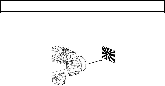
Flangeback adjustment
1.Set the lens iris for manual operation.
2.Open the iris. Set a flangeback adjusting chart about 3 meters distant and adjust the lighting to obtain the correct video output level. If the video level is too high, use a CC/ND filter or electronic shutter.
3.Loosen the Ff ring setscrew.
4.By hand or motor, set the zoom ring to the telephoto position.
5. Observe the flangeback chart image and
turn the distance ring to adjust the focus.
6.Set the zoom ring to the wide angle position.
7.Turn the Ff ring and adjust the focus. Use care not to turn the distance ring.
8.Repeat this process until focus is obtained at both telephoto and wide angle settings.
9.Securely tighten the Ff ring setscrew. ● Also, see the lens operating instructions.
14

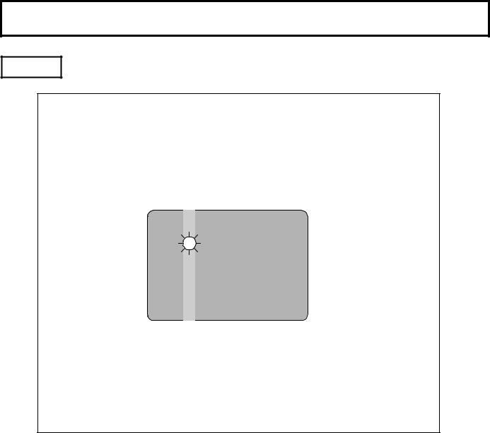
White shading adjustment
White shading adjustment is recommended after replacing the lens. The adjustment relates to the camera vertical coloration. If the lens includes an extender, the shading can be optimized for both extender on and off modes.
(Vertical coloration refers to an effect whereby the image of an overall white sheet of paper tends toward green at the top and magenta at the bottom, or vice versa.)
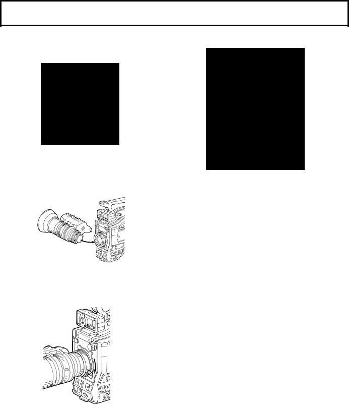
Adjustment steps
1.Install the lens on the camera (be sure to connect the lens cable).
2.Set the electronic shutter to off and the gain to L (0 dB).
3.If provided, set the lens extender to off.
4.Notice that flicker can occur with fluorescent or mercury lighting. Therefore, use sunlight or halogen as the light source.
In the auto iris mode, check that the iris is between F4 and F11. If necessary, adjust the light source position (be sure the electronic shutter is off).
15
 Loading...