

Page 1
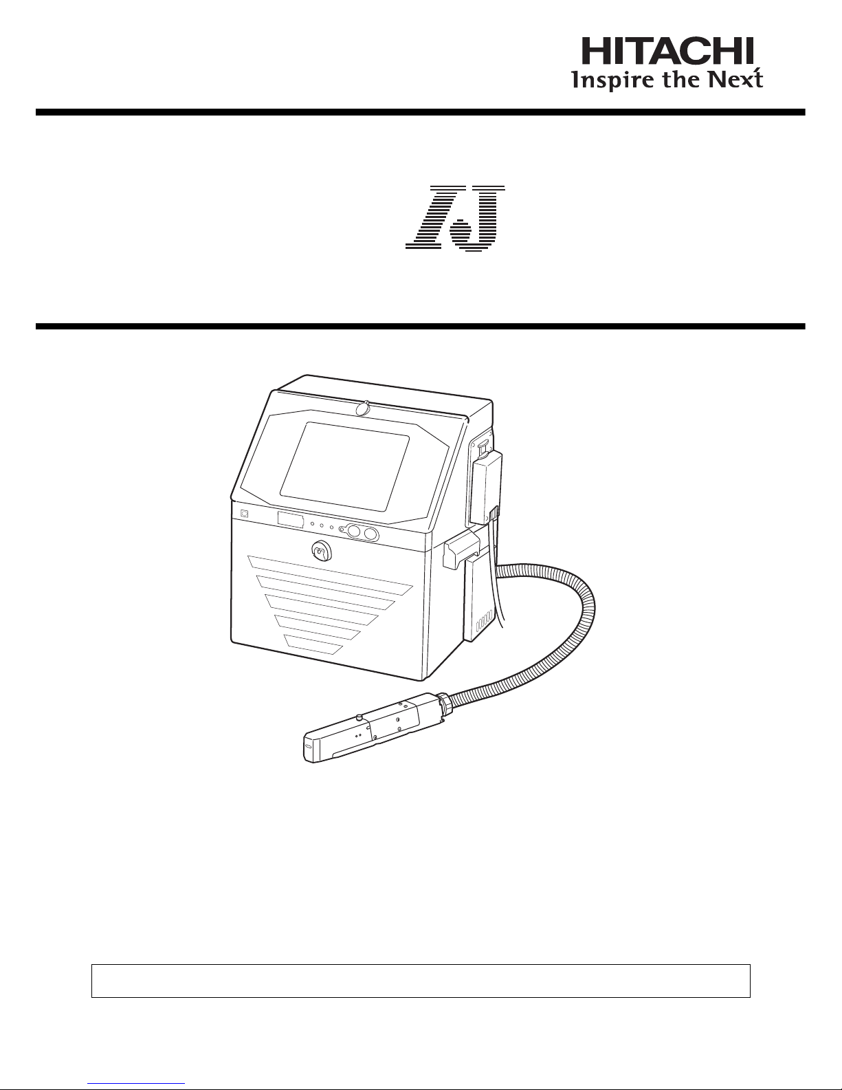
HITACHI Printer
Basic Operation Manual
INK JET PRINTER FOR INDUSTRIAL MARKING
Model UX
Thank you for purchasing the Hitachi IJ Printer Model UX.
This printer employs a noncontact, ink-jet method to print onto a print target.
This Basic operation manual describes the basic handling procedures of the Hitachi IJ Printer Model UX.
If the printer is improperly handled or maintained, it may not operate smoothly and may become defective or
cause an accident. It is therefore essential that you read the Instruction manual to gain a complete
understanding of the printer and use it correctly.
After thoroughly reading the manual, properly store it for future reference.
IF you changed the language of screen by mistake,see the Instruction Manual chapter 7.8 "Selecting Languages".
Page 2

Page 3

●Usege Precautions (1)
Usage Precaution
● Before using the printer, thoroughly read the following safety precautions for optimum printer
use.
● All the instructions set forth in this manual are important and must therefore be observed
without fail.
● After the manual has been read, it must be stored in such a location that all printer operation
personnel can refer to it at all times.
● Please make sure the print status and print content are correct each time when you start
operation of IJP.
● Please implement periodical checkup of print status in the process, even including during
production.
Restrictions on Export
User hereby agrees not to export or re-export this product to any end-user who the user
has reason to suspect may utilize the product for the design, development or reproduction
of nuclear, chemical or biochemical weapons.
The product or system including the product cannot be used in countries or areas other
than those which have concluded a sales contract.
Trademark
File management and USB management are carried out using eParts made from eSOL.
Ethernet is the product name of Xerox Corporation in America.
Page 4
(2) ●Safety Precautions
SAFETY PRECAUTIONS
● You should observe the precautions set forth below in order to use the product properly and
avoid endangering you or other persons or damaging property. For the purpose of clarifying
the severity of injury or damage and likelihood of occurrence, the precautions are classified
into two categories, WARNING and CAUTION, which both describe hazardous situations
that may arise if you ignore the precautions and perform an incorrect handling or operating
procedure. The precautions in these two categories are both important and must therefore
be observed without fail.
WARNING
WARNING is used to indicate the presence of a hazard which
may cause severe personal injury or death if the warning against
performing an incorrect handling procedure is ignored.
CAUTION
CAUTION is used to indicate the presence of a hazard which
may cause personal injury or property damage if the warning
against performing an incorrect handling procedure is ignored.
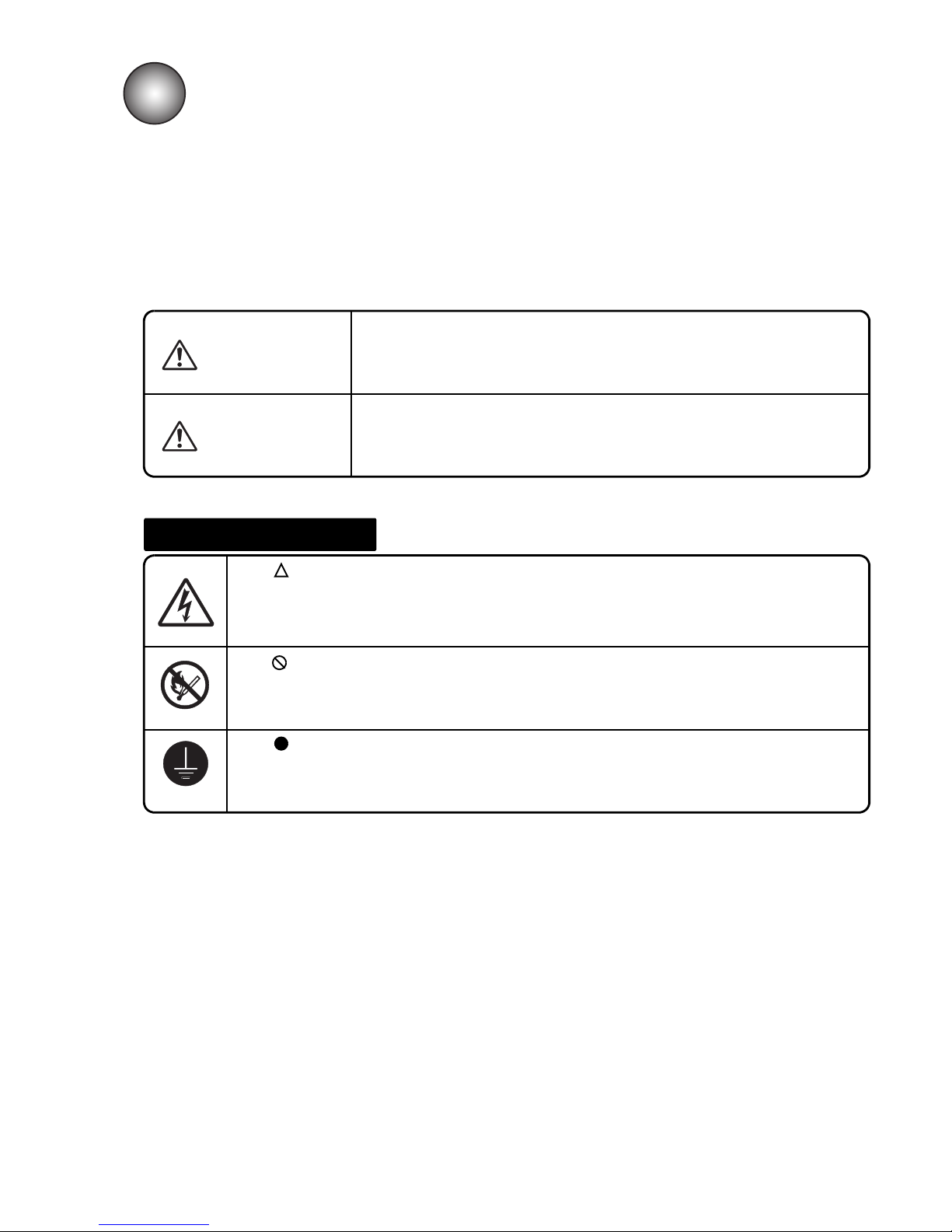
Pictograph Examples
The symbols are used to indicate precautions (including those related to
potential warnings) to be observed. Detailed information is furnished by a picture
within the symbol outline (a shock hazard is indicated by the example shown at
left).
The symbols are used to describe prohibited actions. The details of a
prohibited action are given by a picture within or near the symbol outline (the
example shown at left dictates that you must keep flames away).
The symbols are used to describe required actions. Detailed instructions are
given by a picture within the symbol outline (the example shown at left dictates
that a ground connection must be made).
Page 5
●Safety Precautions (3)
SAFETY PRECAUTIONS (Continued)
CAUTION
● If extraneous noise enters the printer, it may malfunction or break down.
For maximum noise immunity, observe the following installation and wiring
precautions.
Ensure that 100 to 120 VAC or 200 to 240 VAC power cables are not
bundled with other power supply cables.
Insulate the printer main body and print head so that they do not come into
direct contact with the conveyor or other devices.
If the employed print target detector is housed in a metal case, use a plastic
mounting brace for the purpose of insulating the detector from the conveyor
and other devices.
Be sure that the print target detector wiring is not bundled together with other
power supply cables.
1
2
3
4
WARNING
● Ensure that there is no flame- or arc-generating device around the
printer.
The ink and makeup are both flammable and may cause fire.
Fire can be generated by matches, lighters, cigarettes, heaters, stoves, gas
burners, welders, grinders and static electricity. Arcs may be generated from
open-type relays, switches, and brush motors. Before handling the ink and
makeup, remove static electricity from your body, peripheral equipment, and so
on. In the interest of safety, position a dry-chemical fire extinguisher near the
printer.
● Since the ink and makeup contain organic solvents, install the printer at
an adequately ventilated location.
Never install the printer in an enclosed space.
Connect exhaust equipment to the printer in order to prevent it from filling
with organic solvent vapor.
Secure adequate space for the ink/makeup handling area and printer
installation site. At least 200 m must be provided per print head.
Ensure that adequate ventilation is provided.
1
2
Installation Environment of Printer
3
Page 6
(4) ●Safety Precautions
SAFETY PRECAUTIONS (Continued)
WARNING
● Ensure that all electrical wiring, connections and grounding comply with
applicable cords. Properly connect the printer to its dedicated ground.
Complete the above procedure to avoid electrical shock hazards.
● When welding, keep enough space between the IJ printer and the
welding work area to prevent the arc from starting a fire. Also, be sure to
insulate the printhead and IJ printer frame to keep the welding current
from flowing to the control section of the printer, and to make a separate
ground connection for the printer.
● If you wish to receive ink particles in a beaker, for a printing test for
example, use an electrically conductive beaker and connect the beaker
securely to the ground.
Do not let the tip of the printing head enter the beaker.
Ink particles used for printing are electrically charged. An ungrounded beaker
has a gradually rising charge, possibly catching on or causing a fire.
Grounding
WARNING
● Use an AC voltage of 100 to120 V or 200 to 240 V ±10% only and a
power frequency of 50 or 60 Hz only.
If the above requirements are not met, the electric parts may overheat and
burn, creating a risk of fire or electric shock.
Cable Handling
Page 7
●Safety Precautions (5)
SAFETY PRECAUTIONS (Continued)
Ink and Makeup Handling
WARNING
● When charging a refill of ink or makeup, exchanging ink, or otherwise
handling ink or makeup, take enough care not to spill ink or makeup.
If you spill any ink or makeup by mistake, wipe it off neatly and promptly with
wiping paper or something similar. Do not close the maintenance cover until
you make sure that the portion you have just wiped is completely dry.
You must pay particular attention when you have spilled ink or makeup inside
the printer and it is not completely dry. Why? Because vapors of ink or
makeup will stay inside the printer and may catch on or cause a fire.
If you find it hard to wipe the printer when it is turned on, stop it with the maintenance
cover open. Power it down, and then wipe it off again.
● If you wish to clean the casing of the printer with wiping paper impregnated
with makeup, be sure to do so with the power off.
Attempting to clean it when the power is on will cause makeup or vapors of makeup
to enter the printer, possibly catching on or causing a fire.
When the cleaning is over, open the maintenance cover and make sure that no
makeup has entered and no vapors remain inside.
● Should you find a leak of ink or makeup inside the printer while the printer is
running or being maintained, wipe it off promptly with wiping paper or
something similar. Then, with the maintenance cover open, stop the printer,
power it down, and repair the leak.
Continuing operation with a leak of ink or makeup will cause an anomaly,
resulting in abnormal printing.
Ink and makeup are flammable. They may therefore catch on or cause a fire.
● The ink and makeup, their waste solution, used wiping papers and empty
containers are flammable. Waste disposal must comply with appropriate
regulations. Consult the appropriate regulatory agency for further information.
CAUTION
● Since the ink and makeup contain organic solvents, observe the following
handling precautions.
When handling the ink or makeup, wear protective gloves and safety goggles to
avoid direct skin contact. If the ink or makeup comes into contact with skin, wash
thoroughly with soap and warm or cold water.
When transferring the ink or makeup to or from a bottle, exercise caution to
prevent it coming into contact with the printer or surrounding articles.
If there is any spillage, immediately wipe it clean using a cloth moistened with
makeup.
● Ink and makeup must be stored as flammable liquids. Storage must comply
with local regulatory requirements. Consult the appropriate regulatory
agency for further information.
1
2
Page 8
(6) ●Safety Precautions
SAFETY PRECAUTIONS (Continued)
Main Body Handling
WARNING
● Do not insert tweezers, a screwdriver, or any other metal article into the ink
ejection hole in the end of the print head.
When the printer is ready to print, a high voltage (approximately 6 kV) is applied to
the deflection electrode section in the print head.
Exercise caution to avoid electric shock, injury, and fire.
● Do not remove covers and/or screws which are not specified on this manual.
A high voltage is applied to some sections of the printer.
Exercise caution to avoid electric shock and injury.
● Exercise caution to avoid inadvertently disconnecting, forcibly pulling, or
bending piping tubes.
Since the ink and makeup in some portions of piping tubes are pressurized, they
may splash into your eyes or mouth or onto your hands or clothing.
If any ink or makeup enters your eyes or mouth, immediately flush with warm or cold
water and consult a physician.
● While the printer is operating, do not look into the ink ejection hole in the end
of the print head.
Ink or makeup may enter your eyes or mouth or soil your hands or clothing.
If any ink or makeup enters your eyes or mouth, immediately flush with warm or cold
water and consult a physician.
● When ejecting the ink, do it after confirming that there is no one in the ejection
direction.
(Operate with the end of the print head inserted in a beaker, etc.)
● Before servicing the printer, be sure to stop the ink ejection.
Because ink or makeup may splash into your eyes or mouth or onto your hands or
clothing. If any ink or makeup enters your eyes or mouth, immediately flush with
warm or cold water and consult a physician.
● If an earthquake, fire, or other emergency occurs while the printer is engaged
in printing or just turned on, press the Main power switch to turn off the power.
CAUTION
● Only persons who have completed an operator training course for
Hitachi IJP can operate and service the printer.
If the printer is operated or serviced incorrectly, it may malfunction or break down.
● Do not attempt to make repairs for any purpose other than operation or
maintenance.
Page 9
●Safety Precautions (7)
Related Regulations
WARNING
● Never drain the ink or makeup waste solution into a public sewer system.
Waste disposal must comply with all appropriate regulations.
Consult the appropriate regulatory agency for further information.
● The printer must be managed in compliance with all appropriate regulations.
Read and understand the appropriate Safety Data Sheet (SDS) before using any ink
or makeup.
SAFETY PRECAUTIONS (Continued)
FCC Notice
This device complies with part 15 of the FCC Rules. Operation is subject to the following two
conditions: (1) This device may not cause harmful interference, and (2) this device must accept
any interference received, including interference that may cause undesired operation.
This equipment has been tested and found to comply with the limits for a Class A digital device,
pursuant to part 15 of the FCC Rules. These limits are designed to provide reasonable protection
against harmful interference when the equipment is operated in a commercial environment.
This equipment generates, uses, and can radiate radio frequency energy and, if not installed and
used in accordance with the instruction manual, may cause harmful interference to radio
communications. Operation of this equipment in a residential area is likely to cause harmful
interference in which case the user will be required to correct the interference at his own expense.
Page 10
(8) ●Safety Precautions
WARNING
<Keep all fire away.>
○ Ink and Makeup are flammable.
○ All fire must be kept away from the machine.
○ Spilled Ink and Makeup must be wiped off and dried up immediately.
<Caution when handling Ink/Makeup>
○ Strage must comply with local regulatory requirements .
○ Read and understand Safety Data Sheet(SDS).
○ Be sure to wear protective gloves and safety goggies.
○ If the Ink/Makeup in used is an organic solvent,it must be managed in compliance with the
Ordinance on the prevention or Organic Solvent poisoning.Refer to the "Instruction Manual"and
the "Handling guidance of each ink" for details.
AVERTISSEMENT
< Tenir hors de portée du feu. >
○ L’encre et la composition sont inflammables.
○ Tenir la machine hors de portée du feu.
○ Nettoyez et séchez immédiatement les projections d’encre et de composition.
<Soyez prudent lorsque vous manipulez l’encre/la composition>
○ Le stockage doit respecter les obligations réglementaires locales.
○ Lisez attentivement la fiche signalétique de sécurité de l’appareil (FSSP).
○ Assurez-vous de porter des gants et des lunettes de protection.
○ Si l’encre/la composition utilisée est un solvant biologique, vous devez le manipuler
conformément au décret sur la prévention des empoisonnements par solvant biologique.
Reportez-vous au «Mode d’emploi» et aux «Conseils de manipulation de chaque type d’encre»
pour plus de détails.
SAFETY PRECAUTIONS (Continued)
Page 11

●Contents 1
1. DELIVERED GOODS . . . . . . . . . . . . . . . . . . . . . . . . . . . . 1-1
2. USAGE PRECAUTIONS . . . . . . . . . . . . . . . . . . . . . . . . . . 2-1
2.1 Ink and makeup . . . . . . . . . . . . . . . . . . . . . . . . . . . . . . . . . . . . . . . . . . . . . 2-1
2.2 IJ printer long-term shutdown . . . . . . . . . . . . . . . . . . . . . . . . . . . . . . . . . . . 2-2
2.3 Print head cleaning. . . . . . . . . . . . . . . . . . . . . . . . . . . . . . . . . . . . . . . . . . . 2-3
2.4 Shutdown (no-cleaning stop) . . . . . . . . . . . . . . . . . . . . . . . . . . . . . . . . . . . 2-4
2.5 Cautions on operating time when printer is in service . . . . . . . . . . . . . . . . 2-5
2.6 Heating of ink . . . . . . . . . . . . . . . . . . . . . . . . . . . . . . . . . . . . . . . . . . . . . . . 2-5
2.7 Ink concentration control. . . . . . . . . . . . . . . . . . . . . . . . . . . . . . . . . . . . . . . 2-6
2.8 Gutter cleaning . . . . . . . . . . . . . . . . . . . . . . . . . . . . . . . . . . . . . . . . . . . . . . 2-6
3. COMPONENT NAMES AND FUNCTIONS . . . . . . . . . . . . 3-1
3.1 External views. . . . . . . . . . . . . . . . . . . . . . . . . . . . . . . . . . . . . . . . . . . . . . . 3-1
3.2 Main body internal parts arrangement . . . . . . . . . . . . . . . . . . . . . . . . . . . . 3-3
3.3 Print head . . . . . . . . . . . . . . . . . . . . . . . . . . . . . . . . . . . . . . . . . . . . . . . . . . 3-4
3.4 Screen dispay . . . . . . . . . . . . . . . . . . . . . . . . . . . . . . . . . . . . . . . . . . . . . . . 3-5
4. INSTALLING PRECAUTIONS . . . . . . . . . . . . . . . . . . . . . 4-1
5. INSTALLATION CHECK ITEMS . . . . . . . . . . . . . . . . . . . . 5-1
5.1 Print head air purge . . . . . . . . . . . . . . . . . . . . . . . . . . . . . . . . . . . . . . . . . . 5-1
6. ELECTRIC SIGNAL CONNECTION . . . . . . . . . . . . . . . . . 6-1
6.1 Wiring precautions . . . . . . . . . . . . . . . . . . . . . . . . . . . . . . . . . . . . . . . . . . . 6-1
7. BASIC OPERATION . . . . . . . . . . . . . . . . . . . . . . . . . . . . . 7-1
7.1 Start operation . . . . . . . . . . . . . . . . . . . . . . . . . . . . . . . . . . . . . . . . . . . . . . 7-1
7.1.1 Start operation . . . . . . . . . . . . . . . . . . . . . . . . . . . . . . . . . . . . . . . . . . . . . . . . . . . . . . 7-1
7.1.2 When an error occurred at the start of operation . . . . . . . . . . . . . . . . . . . . . . . . . . . . 7-5
7.1.3 Ready and Standby state switching operation . . . . . . . . . . . . . . . . . . . . . . . . . . . . . 7-10
7.1.4 Specifying the login user . . . . . . . . . . . . . . . . . . . . . . . . . . . . . . . . . . . . . . . . . . . . . 7-12
CONTENTS
Page 12

2 ●Contents
7.2 Shut down operation . . . . . . . . . . . . . . . . . . . . . . . . . . . . . . . . . . . . . . . . .7-13
7.2.1 Automatically stopping by pressing one button (UX-D,E only) . . . . . . . . . . . . . . . . . 7-13
7.2.2 Stopping ink ejection by pressing the screen button. . . . . . . . . . . . . . . . . . . . . . . . . 7-14
7.2.3 Turning off the main power switch . . . . . . . . . . . . . . . . . . . . . . . . . . . . . . . . . . . . . . 7-16
7.2.4 Careful Cleaning . . . . . . . . . . . . . . . . . . . . . . . . . . . . . . . . . . . . . . . . . . . . . . . . . . . . 7-17
7.3 Basic operation . . . . . . . . . . . . . . . . . . . . . . . . . . . . . . . . . . . . . . . . . . . . .7-18
7.3.1 Operating Scheme(New HMI). . . . . . . . . . . . . . . . . . . . . . . . . . . . . . . . . . . . . . . . . . 7-18
7.3.2 Operating Scheme(Previous HMI) . . . . . . . . . . . . . . . . . . . . . . . . . . . . . . . . . . . . . . 7-19
7.3.3 Change procedure of (New HMI) ⇔ (Previous HMI) . . . . . . . . . . . . . . . . . . . . . . . . 7-22
8. INK AND MAKEUP REPLENISHMENT . . . . . . . . . . . . . . 8-1
8.1 Replenishing the ink. . . . . . . . . . . . . . . . . . . . . . . . . . . . . . . . . . . . . . . . . . .8-2
8.2 Replenishing the makeup . . . . . . . . . . . . . . . . . . . . . . . . . . . . . . . . . . . . . .8-8
9. WHEN WARNING OR FAULT WAS GENERATED . . . . . . . .9-1
9.1 Display when warning or fault was generated . . . . . . . . . . . . . . . . . . . . . . .9-1
9.2 When checking the warning and fault generation status . . . . . . . . . . . . . . .9-5
9.3 Remedial action to be taken in the event of a printing failure . . . . . . . . . . .9-6
10. TROUBLESHOOTING GUIDE . . . . . . . . . . . . . . . . . . . 10-1
11. MAINTENANCE SERVICE . . . . . . . . . . . . . . . . . . . . . . 11-1
12. EMERGENCY PROCEDURES . . . . . . . . . . . . . . . . . . . 12-1
13. SPECIFICATIONS . . . . . . . . . . . . . . . . . . . . . . . . . . . . . 13-1
14. SCHEMATIC DIAGRAMS . . . . . . . . . . . . . . . . . . . . . . . 14-1
14.1 Outside Dimensions. . . . . . . . . . . . . . . . . . . . . . . . . . . . . . . . . . . . . . . . .14-1
15. APPENDIX . . . . . . . . . . . . . . . . . . . . . . . . . . . . . . . . . . 15-1
● Index . . . . . . . . . . . . . . . . . . . . . . . . . . . . . . . . . . . . . . . . . . . . . . . . . . . . . . .15-1
Page 13
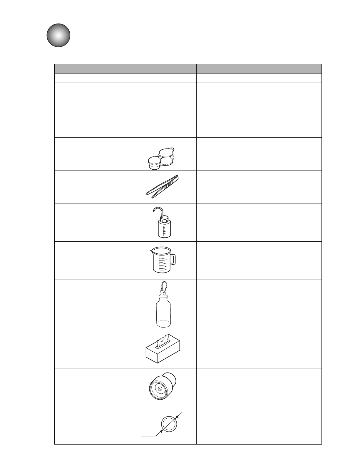
●Delivered goods 1-1
No. Part Name Qty Product code. Remarks
1 IJ printer body 1 -
2 Basic Operation manual 1 -
3Manual CD 1 -
The instruction manual and
technical manual are provided.
Be sure to read the manuals
thoroughly and get a good
understanding so you can use the
printer correctly.
4 One-page sheet 1 -
5 Magnifying glass 1 451274
Used in ink particles shape check,
ink beam position check, etc.
6 Tweezers 1 451412
Used when removing the
orifice, etc.
7 Cleaning bottle 1 451058
Filled with makeup and used in
print head cleaning, etc.
8 Beaker with handle 1 451410
Used in print head cleaning, ink
replacement, etc.
9 Waste solution bottle 1 -
Used when replacing ink and
filter.
10 Wiping paper 1 -
Use for wiping after print head
cleaning, etc.
11 Mini Filter 1 451857
Recovery filter, Makeup filter
(Spare parts)
12 O-ring SF7000-5.6 1 451589
An O ring for the orifice plate seal
(spare part).
1. DELIVERED GOODS
●Unpack the equipment and check the delivered goods.
φ7.2
Page 14
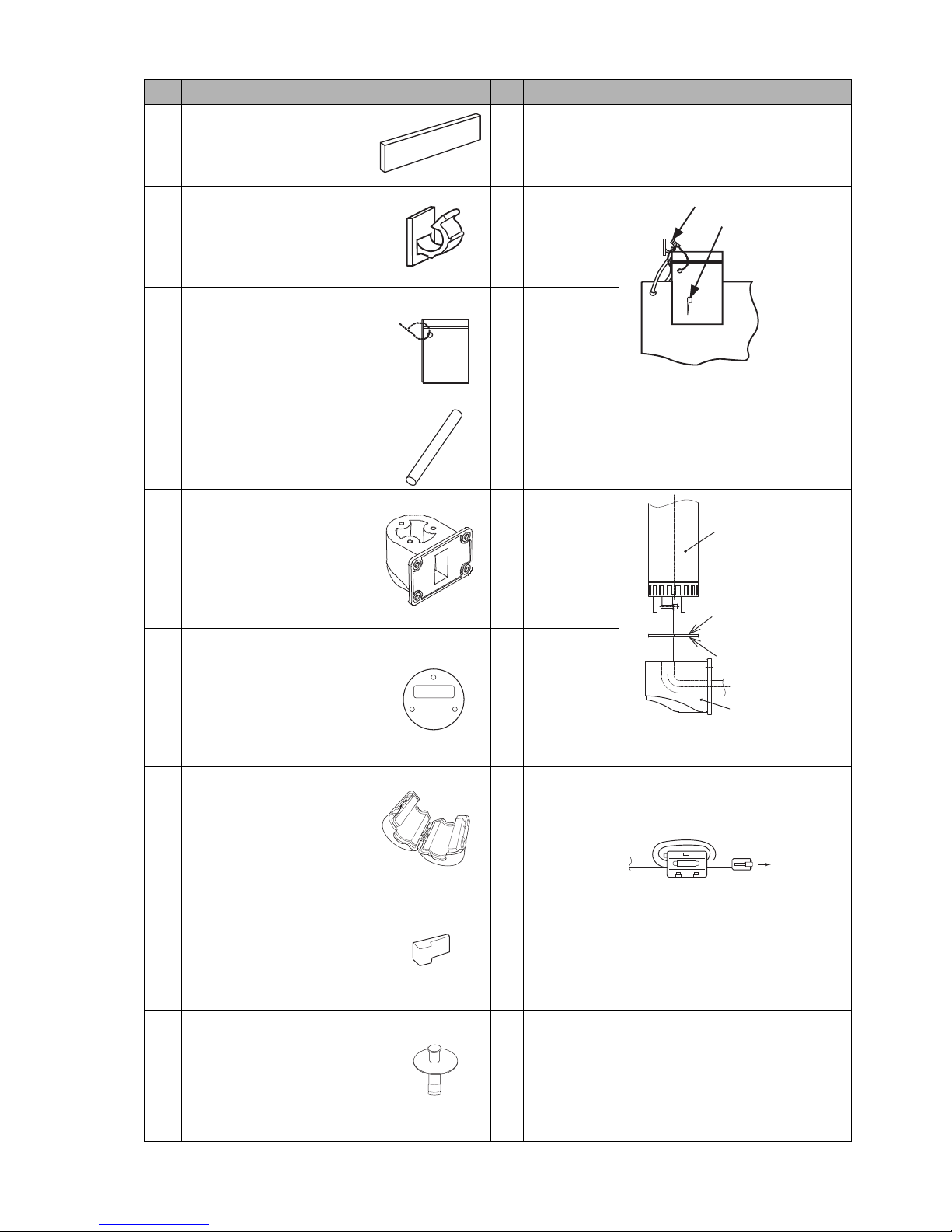
1-2 ●Delivered goods
No. Part Name Qty Product code Remarks
13 Cable seal 3 -
Seal for power cable and
external communications cable.
14 Cable clip 1 -
15 Plastic bag with zipper 1 -
16 Drainage tube 1 -
Used when replacing ink and
filter.
(If using a beaker instead of the
waste solution bottle)
17 Signal tower holder 1 -
Used for attaching the signal
tower.
18 Signal tower holder plate 1 -
19 Ferrite core 1 -
Attach to LAN cable when using
TUP-I.
Install by wrapping the cable 1
turn as shown in the figure below.
20
(*1)
Nozzle rubber seal 1 -
This part is used when IJ Printer is
shutdown for several days, or
pursuant to “6.16.1 Process prior
to long-term shutdown” in
Technical Manual. This parts is
mounted on the print head when
the product is delivered.
21
(*1)
Supply port cap 2 -
This part is used when IJ Printer is
shutdown pursuant to “6.16.1
Process prior to long-term
shutdown” in Technical Manual.
This parts is mounted on the Ink or
Makeup reservoir when the
product is delivered.
Cable clip
Nozzle rubber seal
One page sheet
Use to store the one page
sheet and nozzle rubber seal.
Note “Part Name” and “Product code” when ordering the parts.
(*1) Store these parts in a plastic bag, etc., to protect it form dirt and dust.
Signal tower
Holder plate
(Packing)
Holder
To TUP-I
Page 15
●Ink and makeup 2-1
2.1 Ink and makeup
(1) Ink and makeup replenishment
The printer employs an automatic ink/makeup replenishment system. While the printer is operated, the
ink reservoir automatically supplies the ink and the makeup reservoir automatically supplies the makeup
to the ink main tank at regular intervals. If the ink or makeup replenisher level is too low, an alarm is
issued. In this case, replenish the ink or makeup without delay.
(For the replenishment procedures, see Section 8.)
(2) Ink periodic replacement
For the replacement procedures, see “Technical Manual Chapter 6”.
●While the IJ printer ink circulates for operations, it reacts with the atmospheric air elements and
deteriorates with time. Therefore, it needs periodic replacement. The guide for determining the
replacement interval conforms to the handling guidance of each ink.
*What is makeup? :
The makeup serves as the replenisher that makes up for the constituent loss due to ink
evaporation during ink ejection. It is also used as a cleaning solution.
2. USAGE PRECAUTIONS
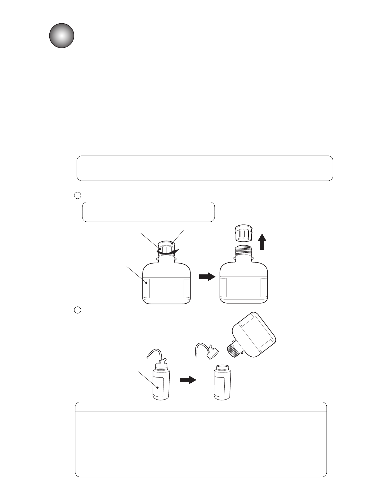
(3) When using the cartridge bottle makeup as the cleaning solution
Open the makeup cartridge bottle by turning its cap.
1
● Do not remove the over cap.
CAUTION
Use the makeup by transferring it to the cleaning bottle.
2
Over cap
Cap
Makeup
cartridge bottole
Cleaning bottole
● If the cleaning solution is not available, pour the makeup of the makeup cartridge
bottle into the cleaning bottle before the makeup cartridge bottle is set.
● Tighten the cap of the makeup cartridge bottle after use.
Turn it upside down to check if there is No leakage of makeup.
● If the makeup in the makeup cartridge bottle is used as cleaning solution, the
content of makeup in the makeup cartridge bottle is reduced.
When it is set in the printer, please use the makeup cartridge bottle which contains
more than half of its content.
● In the makeup accidentally spilled, promptly wipe it up with the wiping paper.
CAUTION
Page 16
2-2 ●IJ printer long-term shutdown
2.2 IJ printer long-term shutdown
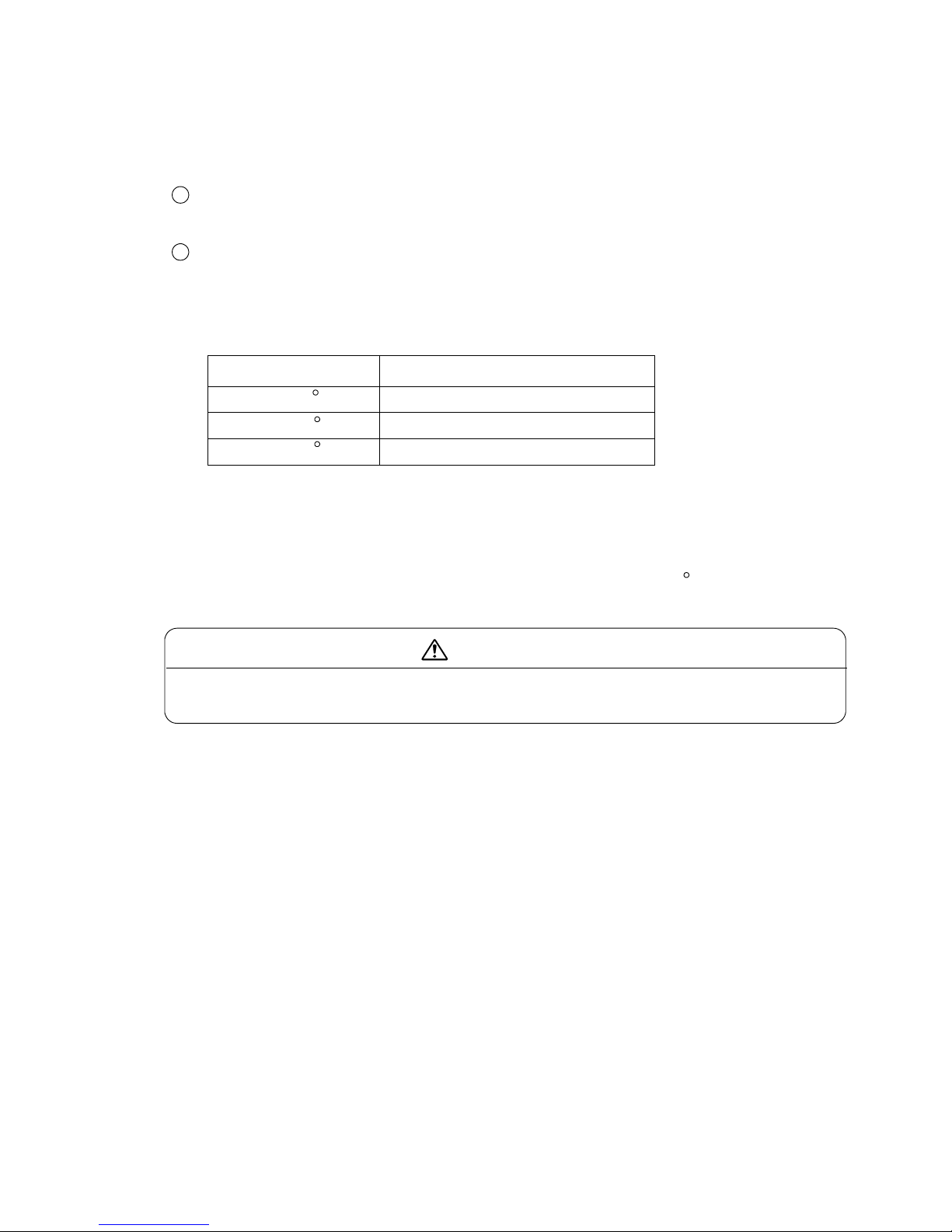
When the IJ printer is shut down for a long time due to production or other circumstances, the ink may
accrete inside of the printer and cause such problems as inability to be ejected or to be recovered. When
this occurs, the following actions must be taken.
Prevent accretion by operating the printer periodically.
Operate (eject ink) the printer for 1 hour or longer at least once during the “Shutdown Period
Guideline” shown in the table below.
Perform long-term shutdown storage work.
Before storage, drain the ink from inside the printer and fill the printer with makeup.
When restarting operation after storage, drain the makeup from inside the printer and fill the printer
with ink.
Refer to Technical manual “6.16 Long-term Shutdown” for detail.
Storage temperature Shutdown Period Guideline *1
0 to35 C 3 weeks
35 to 40 C 2 weeks
40 to 45 C 1 week
1
2
Since “Perform long-term shutdown storage work” requires special work,
it is recommended to contact your local distributor and ask for the work.
CAUTION
*1: Maximum period the printer can be continuously shut down without being operated.
● The values in the table are for MEK based ink.
● Handling of ink other than the above requires special handling in accordance with the
handling guidance of each ink.
● To prevent adhesion, store the equipment at the lowest temperature possible.
● Please note the ink may harden within a week when it is stored in 45
C or higher.
Page 17
●Print head cleaning 2-3
2.3 Print head cleaning
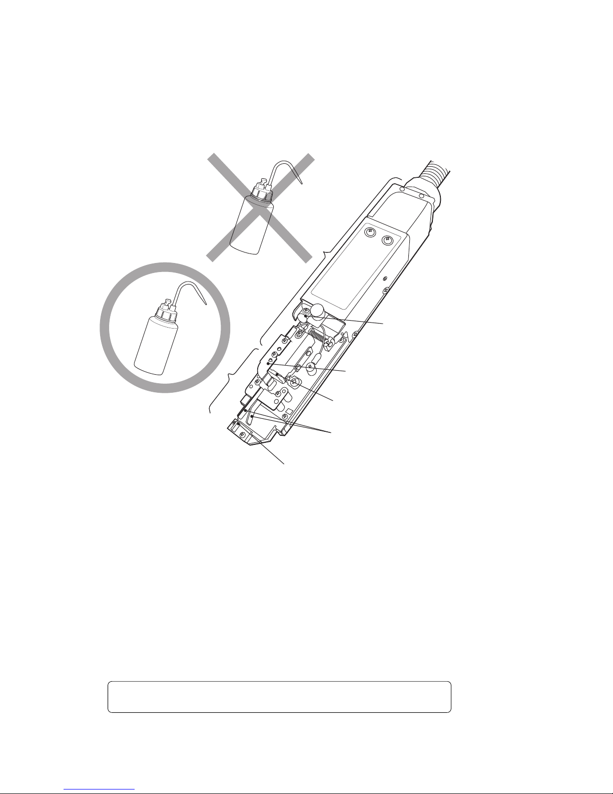
Take the following precautions when cleaning ink from around the nozzle.
(1) Orient the end of the print head downward and pour makeup onto the dirty part and clean while
catching the makeup in a beaker.
(2) After cleaning, thoroughly wipe the print head with wiping paper and allow it to dry.
●Thoroughly dry the nozzle, charge electrode, deflection electrode, mounting base and fringe of the gutter.
Confirm that the parts are sufficiently dry before starting the next operation.
If operated while wet, the printer will not start normally.
●While the print head is wet, do not orient its end upward.
(3) Never immerse the print head in the makeup.
(4)When printing is frequently performed or the distance between the print material and the print head is short,
ink splashes may stain the end of the print head and the print head cover. If this condition is left unresolved, the
stained status will be made worse, resulting in a print error or emergency stop. If a print error or emergency
stop frequently occurs because of stain due to ink splashes, stop the operation in progress and clean the end of
the print head (around the nozzle, charge electrode, deflection electrode, mounting base and gutter) and the
print head cover. Do this in addition to the cleaning to be performed at the end of each day’s work.
Air purging of the print head is effective against staining due to ink splashing.
See the Technical Manual “3.1 Print head air purge”.
Cleaning range
Do not pour the makeup over this section.
Wipe the print head clean with wiping paper
dampened with the makeup.
Nozzle
Deflection electrode
Charge electrode
Gutter
Page 18

2-4 ●Shutdown
2.4 Shutdown (no-cleaning stop)
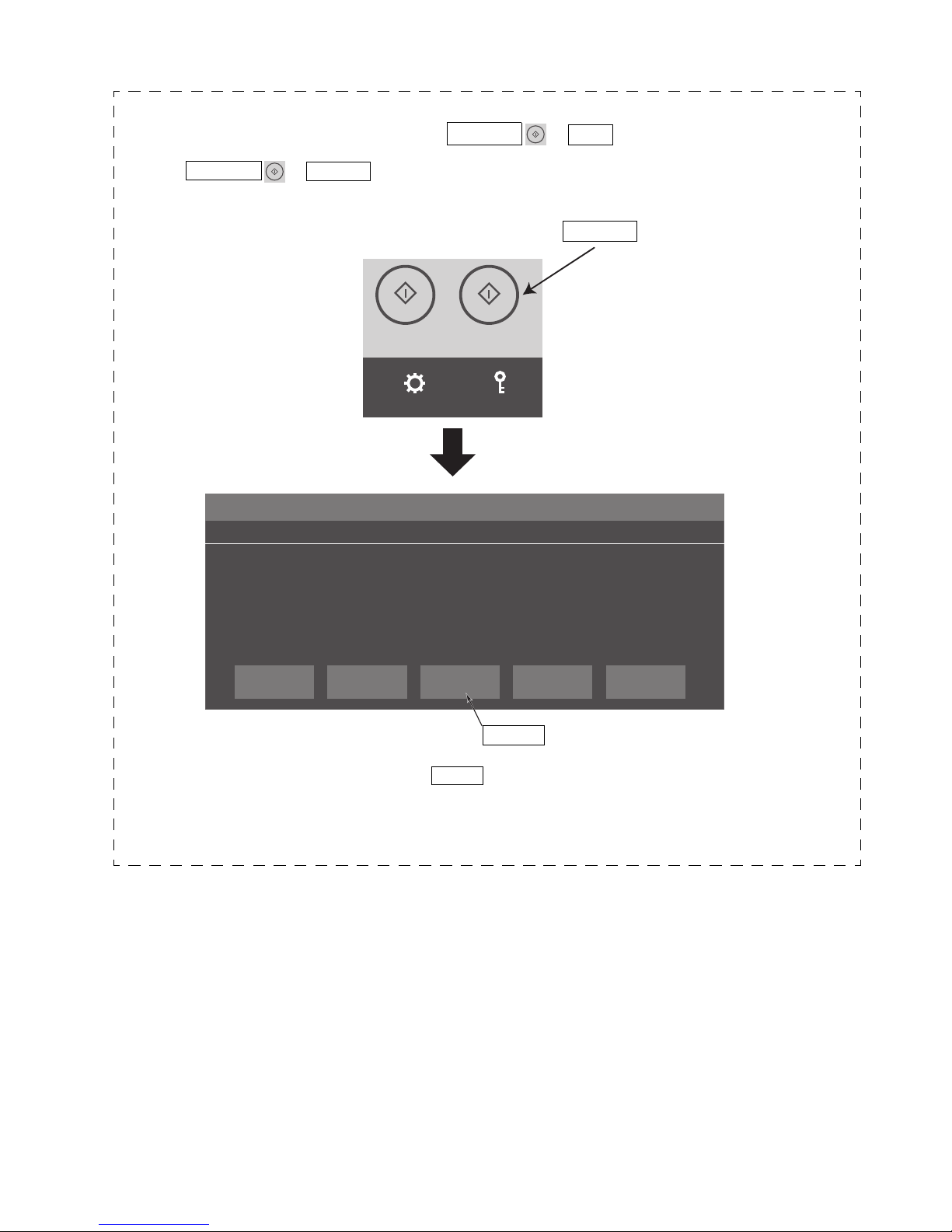
When you press the SHUTDOWN → OK at HOME screen, the printer stops after completing its automatic
nozzle cleaning sequence. If you repeatedly activate the SHUTDOWN → OK to stop an operation,
excessive makeup will enter the printer, thereby thinning the ink or producing an unduly high ink main tank
solution level. If it is absolutely necessary to repeatedly stop the printer operation, use the following procedure.
(For detail the HOME screen, refer to “Instruction Manual”.)
TEST
STARTPRINTING
SHUTDOWN
SETTINGS
LOGIN
Shutdown Process Confirmation
Shutdown will stop the ink jet.
Solution 1. To stop the ink jet, press <OK>.
2. To stop the ink without cleaning, press <No-cleaning stop>.
No.051
CONFIRMATION
×
OK Close
No-cleaning
stop
Press SHUTDOWN at HOME screen, and the message "Shutdown Process
Confirmation" appears.
Press No-cleaning stop on the message "Shutdown Process Confirmation".
*1: Do not use the SHUTDOWN → OK to stop operation more than two successive times.
*2: When operation was stopped using SHUTDOWN → No-cleaning stop , if left in that state, the
ink will become stuck in the nozzle and cause ink stream bending, nozzle clogging, and printing
disturbance. Apply makeup to the nozzle orifice to wash it within 30 minutes after a stop to cause the
ink to eject once again.
1
2
The no-cleaning stop procedure works even while the startup sequence is being executed.
(The SHUTDOWN → OK is inoperative during the startup sequence.)
2
Press SHUTDOWN .
Page 19

●Cautions on operating time when printer is in service 2-5
2.5 Cautions on operating time when printer is in service
(1) Cautions when printer is repeatedly stopped immediately after the start
of operation
If you repeatedly stop the printer immediately after the start of operation, automatic nozzle cleaning at shutdown
will cause the ink in the IJ printer to gradually become thinner. For stable operation of the IJ printer, operate the
printer for a given amount of time or more once started.( =in Ink eject status)
During the operation, the ink viscosity is adjusted automatically and returns to the initial value.
The required amount of operation time varies depending on the ambient temperature or ink types used.
Refer to the handling guidance of each ink for details.
(2) Caution when daily operating time is relatively long
The IJ printer emits an ink jet when printing, so the outside and inside of the print head cover will become dirty
with accumulated ink spillage during operation. To prevent printing defects due to this ink accumulation,
periodically check the head cover and clean it as required.
2.6 Heating of ink
(1) If the ambient temperature is under approximately 20 C, the ink is heated by a heating unit in the print head.
The startup processing time relative to when not operating becomes long.
When not operating: Approximately 1.5 minutes
When operating: Maximum approximately 10 minutes (The rise processing time changes depending on the
ambient temperature.)
(2) When a heating unit fault occurs, take care of the following items.
If a heating unit fault occurs, the messages “Ink Heating Unit too High”, “Ink Heating Unit Temperature
Sensor Fault”, or “Ink Heating Unit Over Current” are displayed and the IJ printer fault stops.
The IJ printer can be restarted by pressing the Reset or Close . However, the ink will not be heated even
if the temperature drops thereafter.
Once “do not perform ink heating” is set, the following message is always displayed whenever the power
is turned on thereafter. Cancel the message by pressing the Close and be sure to inform your nearest
local distributor.
If the printer is temporally operated in "do not perform ink heating" status, the operation of the printer
may become possible by resetting the excitation voltage.
Reset the excitation voltage according to Technical Manual “6.10 Excitation V Adjustment”.
Ink Temperature Correction Notice
The selected setup does not allow ink temperature corrections
to be made.
Solution Contact your local distributor.
No.187
CONFIRMATION
×
Close
1
2
3
Page 20

2-6 ●Ink concentration control
No Ink Concentration Control
The current settings have made ink concentration control
unavailable.
Solution Contact your local distributor.
No.200
CONFIRMATION
×
Close
2.7 Ink concentration control
(1) The ink is automatically controlled to maintain optimum concentration for printing.
(2)If an error occurs in the viscometer which is used to control ink concentration, take care of the following points:
There are three types of viscometer errors:
“Inside Temperature Sensor Fault”, “Viscometer Reading Instability”, and “Viscometer Reading Out of
Range”.
When a “Inside Temperature Sensor Fault” occurs, the unit will enter the fault stop state.
Re-start is possible by pressing the Close , but the setting will be changed to the state in which ink
concentration control based on the measured result using the viscometer is not performed thereafter.
Once the setting of automatic concentration control is released, every time the power is turned on, the
following message will appear. Cancel the message by pressing the Close and be sure to inform your
nearest local distributor.
When “Viscosity Reading Instability” or “Viscosity Readings Out of Range” occurs, the unit will not
enter the fault stop state and printing can be continued. However, you should contact your nearest
local distributor for inspection.
1
2
3
2.8 Gutter cleaning
The IJ printer collects ink not used for printing from the gutter. At the same time, it sucks in atmospheric gas, dust,
and other matter from the air. If these substances are mixed with the ink in the gutter, undissolved
components in the ink or makeup may stick to the gutter. If the system is run for 24 consecutive hours without
automatic cleaning, these components will gradually accumulate in the gutter. This, together with the ink stream
coming into contact with it, may cause such errors as “an error stemming from a dirty head”.
Clean the gutter and its perimeters with makeup periodically.
Perform the procedures descibed in “6.6 Cleaning the Gutter” in Technical Manual, and claen the gutter and the
recovery route.
Should the solution above do not work, contact your nearest distributor.
1
2
Page 21
●External views 3-1
3.
COMPONENT NAMES AND FUNCTIONS
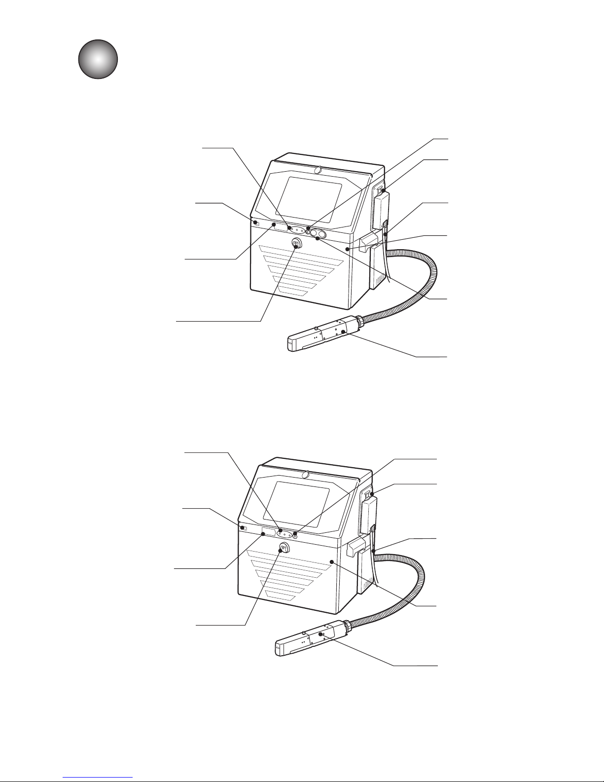
3.1 External views
(1) External views(UX-D,E)
Operating status
indicator lamps
Displays "Ready",
"Fault" and "Warning"
USB cover
On / Stop switch
(*Standard Model only)
Main power switch
Power lamp
Maintenance cover
Opened/closed for ink
and makeup replacement
and other maintenance
purposes.
Print head
This section
performs printing.
Power cable
RFID reader
Reads ID of ink and
makeup for certification.
(2) External views(UX-B)
Power lamp
Main power switch
Power cable
Maintenance cover
Opened/closed for ink
and makeup replacement
and other maintenance
purposes.
Print head
This section
performs printing.
USB cover
Operating status
indicator lamps
Displays "Ready",
"Fault" and "Warning"
Maintenance
cover knob
Pull toward you to open.
Maintenance
cover knob
Pull toward you to open.
RFID reader
Reads ID of ink and
makeup for certification.
Page 22
3-2 ●External views
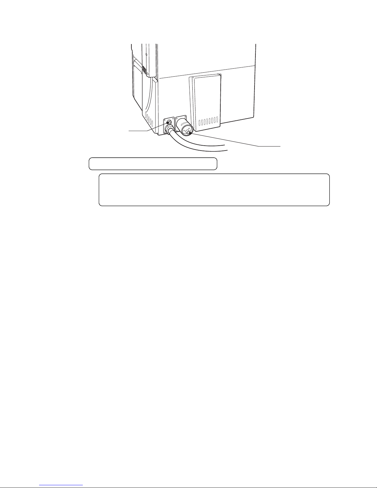
(2) External views (rear side)
Air-purge
connection port
Exhaust duct
connection port
Attention to the instruction of IJ printer
Stainless steel of the main body has the character it not to be easy rust, but it is
a possibility that rust is generated when leaving it for a long time. To prevent rust
being generated, we will recommend that the surface of the main body be kept
clean as much as possible.
Page 23
●Main body internal parts arrangement 3-3
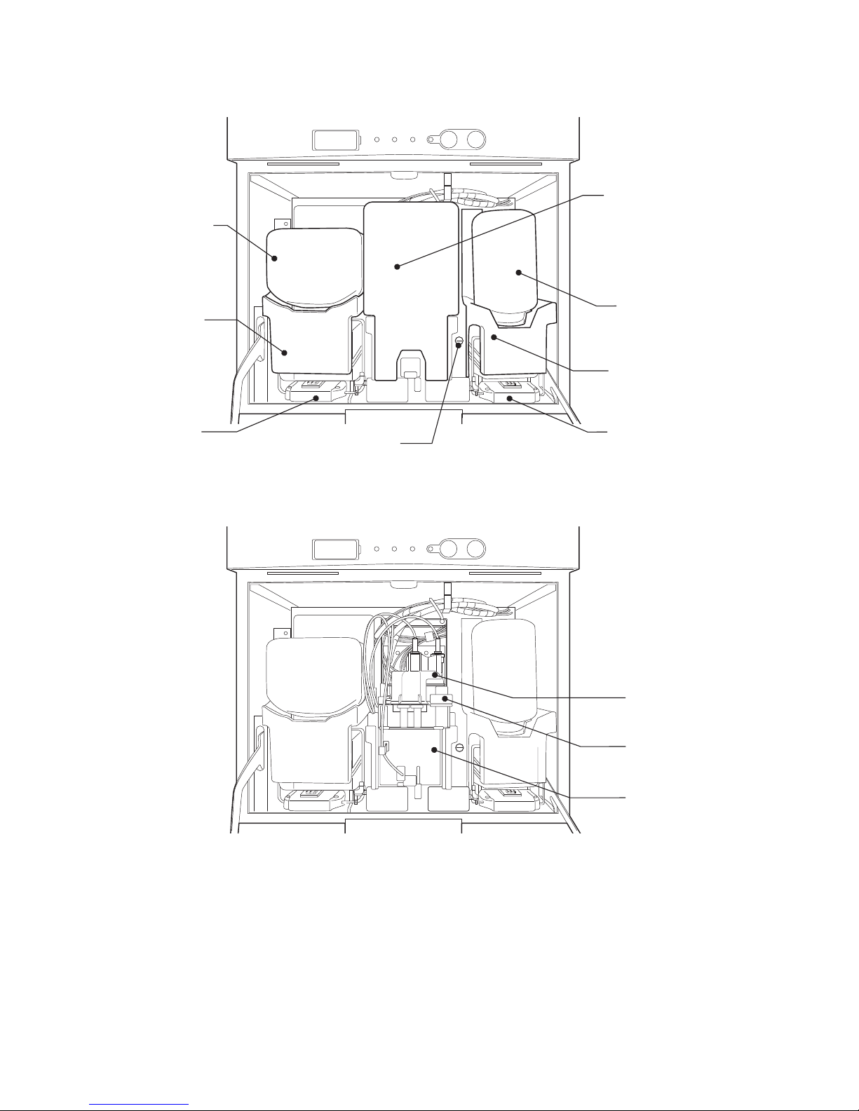
3.2 Main body internal parts arrangement
Makeup
reservoir
Ink reservoir
Recovery filter
Ink filter
Main ink tank
Inner cover
Ink cartridge bottle(*1)
Makeup
cartridge bottle
(*1)
Appearance with inner cover removed
(*1) The Ink cartridge bottle and the makeup cartridge bottle are optional parts.
Lever handleLever handle
Pressure adjusting screw
Page 24
3-4 ●Print head
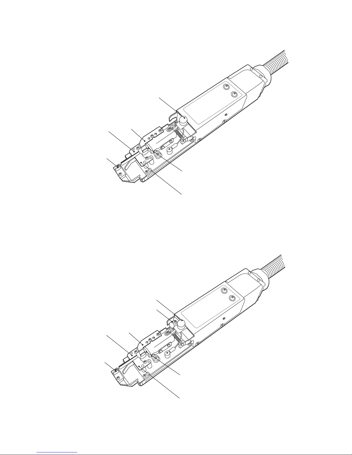
3.3 Print head
Print head cover lock thumbscrew
Nozzle orifice
Minus deflection electrode
Gutter
Plus deflection electrode
Charge electrode
Plus deflection electrode
Nozzle orifice
Gutter
Minus deflection electrode
Charge electrode
Print head cover lock thumbscrew
[UX-D,B]
[UX-E]
Air exhaust port
Page 25
●Screen display 3-5
Printdescription
2015.07.0712:45
SETTINGS
LOGINEDITADJUSTSAVEOPENHOME
Operating Time Ink Presure
(Standard Value:
0.255
)
100
h
0.000
MPa
Print Count
1.000
Makeup Ink
TEST
START PRINTING
STARTUP
100%
+−
OFFLINE
STOP
ID:User2
×
Print description
2015.07.0712:45
Menu
Com=0
[Stop ]
Ink operating time 100(hours)
Cumulative op. time 100(hours)
Print count 1000(prints)
Ink pressure 0.000(MPa;standard value:0.255)
Change
message
Select
message
Overwrite
message
Adjustprint
parameters
Operation
management
Message name[ ]
− +
Current user ID : user2
Interlaced
Printcount
reset
Startup
Manual
Makeup Ink
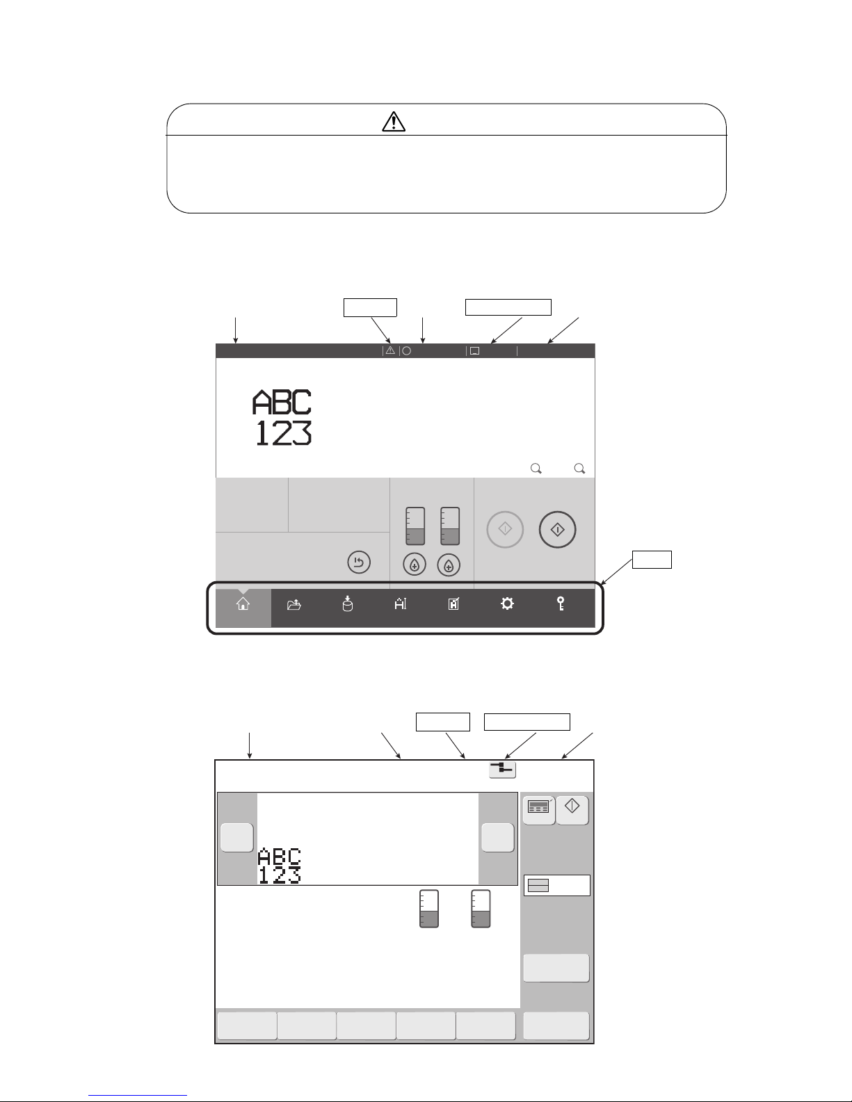
3.4 Screen display
● For operation of Menu, refer to "Instruction Manual".
Menu
Status
Warning Offline/Online
Status
Warning Offline/Online
Screen name Current time
[New HMI]
[Previous HMI]
Screen name Current time
● A touch panel is employed for data entry to operation screen.
When manipulating the Touch panel, use only fingers. If the touch panel is operated
with metal and/or sharp objects such as ball point pen, it may malfunction or break
down.
CAUTION
(1) Print description screen (initial screen)
For details of screen, refer to "Instruction Manual".
Page 26
3-6 ●Screen display
?
Main Ink Tank Too Full
The ink level in the main ink tank is too high.
Cause 1. The valve (MV2) or valve (MV7) is faulty.
2. The High Level sensor in the main ink tank is faulty.
Solution 1. Drain proper amount of ink in the main ink tank.
2. Check the High Level sensor.
3. Contact your local distributor.
No.002
Fault
×
Close
Reset
?
◆◆◆◆◆ Main Ink Tank Too Full002
The ink level in the main ink tank is too high.
Cause 1. The valve (MV2) or valve (MV7) is faulty.
2. The High Level sensor in the main ink tank is faulty.
Solution 1. Drain proper amount of ink in the main ink tank.
2. Check the High Level sensor.
3. Contact your local distributor.
Reset
Close
HELP
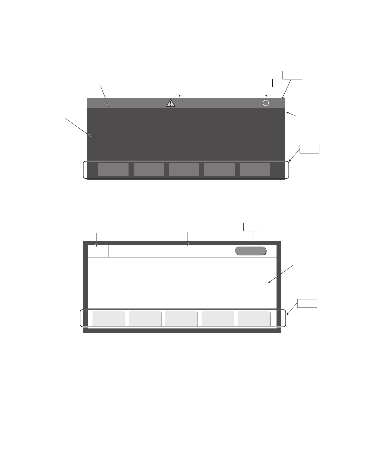
(2) Message
For details of message, refer to "9. When Warning or Fault was generated".
[New HMI]
[Previous HMI]
Message name
Message type
Message No.
The Description,
Cause and
Solution
Button
Close
HELP
Message No.
Message name
HELP
The Description,
Cause and
Solution
Button
Page 27
●Installing Precautions 4-1
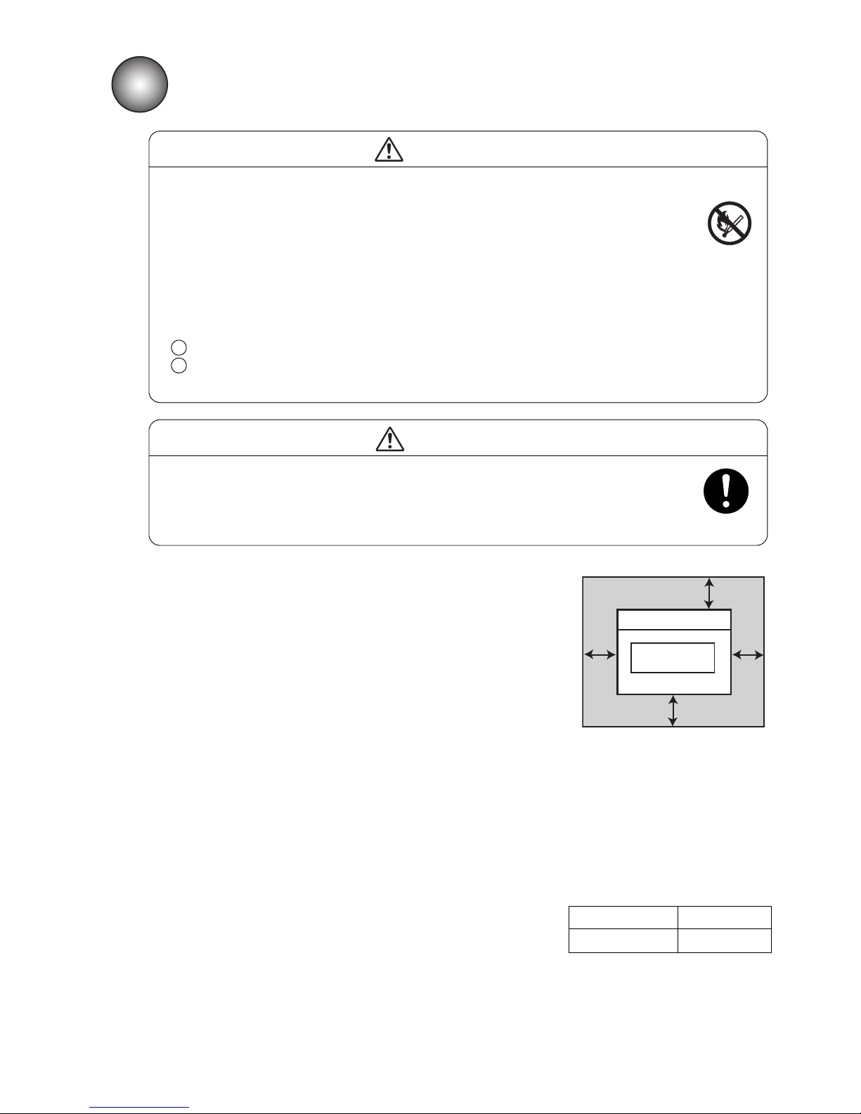
● The employed ink and makeup contain organic solvents. Furnish an
adequate space for the ink/makeup handling area and printer
installation site. A space of at least 200 m must be provided per print head.
Ensure that adequate ventilation is provided. Follow all regulation in your
country.
CAUTION
3
IJ printer
Maintenance area
300
mm
Top view
300
mm
300mm
750mm
4. INSTALLING PRECAUTIONS
● Ensure that there is no flame- or arc-generating device around the printer.
The ink and makeup are both flammable and may cause fire.
Fire can be generated by matches, lighters, cigarettes, heaters, stoves, gas burners,
welders, grinders and static electricity. Arcs may be generated from open-type relays,
switches, and brush motors. Before handling the ink and makeup, remove static
electricity from your body, peripheral equipment, and so on. In the interest of safety,
position a dry-chemical fire extinguisher near the printer.
● Since the ink and makeup contain organic solvents, install the printer at an
adequately ventilated location.
Never install the printer in an enclosed space.
Connect exhaust equipment to the printer in order to prevent it from filling with
organic solvent vapor.
WARNING
2
1
(1) Provide a clearance around the IJ printer for daily operation,
handling, and maintenance access (see the figure at right).
(2) The print head needs to be cleaned with the makeup while the
printer is operated and stopped (daily maintenance). Adopt a fixed
structure in consideration of print head cover and print head
removal.
(3) Installation must be completed so that no vibration will be applied to
the IJ printer main body, print head, or print head cable.
If they are vibrated, print quality deterioration and print irregularity
may be incurred (the maximum permissible vibration value is
1.96m/s ).
(4) The IJ printer main body must be installed with a levelness error of
not over ±1°.
(5) The IJ printer main body must be electrically insulated from the
other equipment (conveyors, packing machines,etc.), photoelectric
switches, and the rotary encoder.
(6) The standard distance between the printing head and the object to be
printed on is as indicated in the right-hand table.
The smaller the clearance between the print head and print target,
the smaller the character height and the better printing.
(7) The IJ printer proper requires maintenance as the occasion may
demand including replenishment of ink and makeup and
replacement of filter.
(8) If ambient humidity is 85 to 90%RH, you must purge inside of print
head by air.
It is necessary for dry-clean air, regulator for pressure of air and air
filter.
(Quantities of the air are 1L / minutes.)
* Leave a maintenance area of
at least 20 cm for the upside
of printer.
Distance between the printing head
and the object to be printed on
Nozzle diameter Distance
65μm
10 to 30mm
2
Page 28
4-2 ●Installing Precautions
Upward printing
Lateral printing
Downward printing
Print head
cable included
1m
1.5m
Print head
Print head cable
Main body installation surface
IJ printer
main body
Upward
printing
Lateral
printing
Downward
printing
Print head
cable included
1m
1.5m
Print head
Print head cable
Main body installation surface
IJ printer
main body
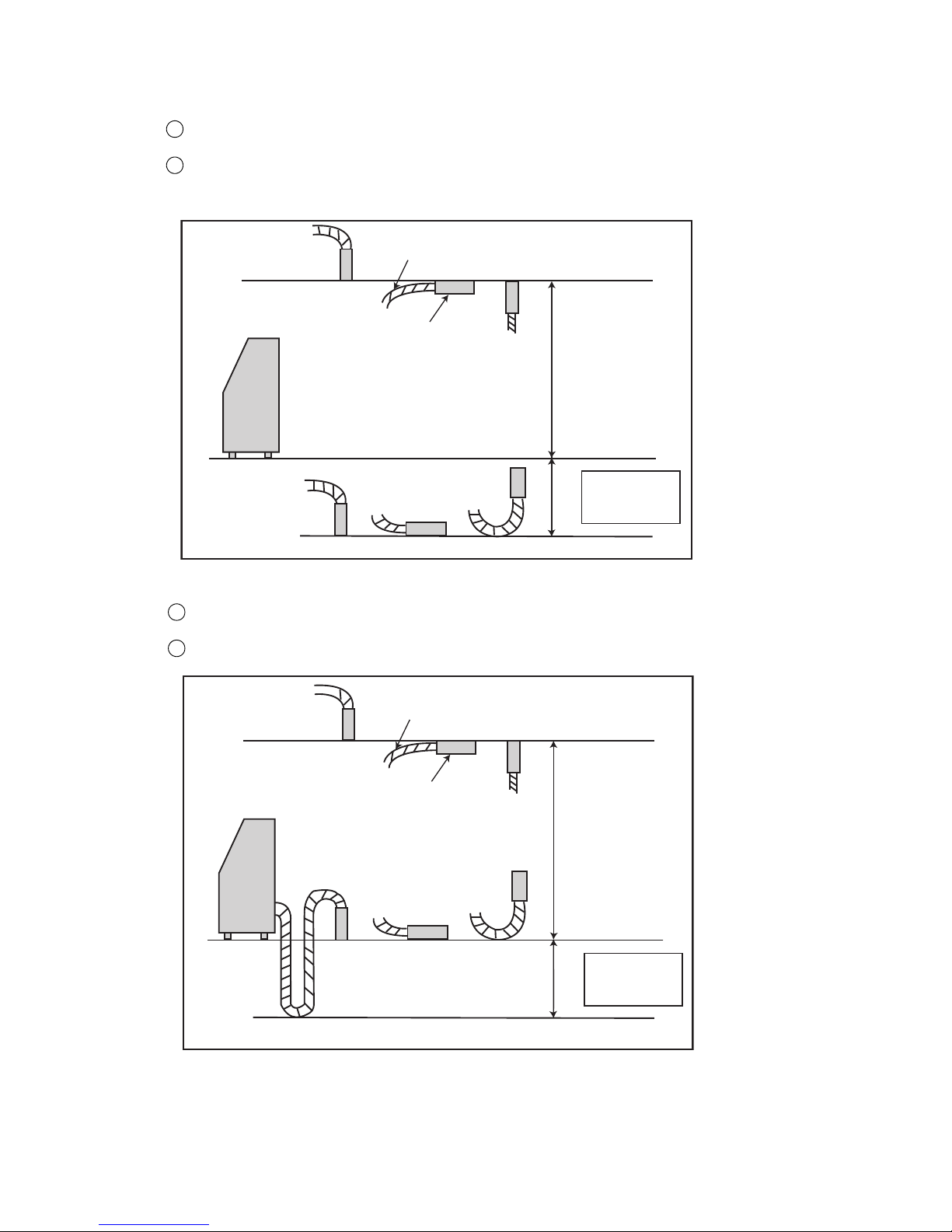
(9) When installing the print head and print head cable, comply with the following conditions or it will
increase the risk of degraded performance of the ink supply and ink recovery behavior.
a) 0 to 45 ℃
When positioning the end of the print head above the printer main body installation surface,ensure
that the distance between the end of the print head and the installation surface does not exceed 1.5 m.
When positioning the end of the print head below the printer main body installation surface, ensure
that the distance between the end of the print head and the installation surface does not exceed 1 m.
2
1
b) 45 to 50 ℃
When positioning the end of the print head above the printer main body installation surface,ensure
that the distance between the end of the print head and the installation surface does not exceed 1.5 m.
Do not install the end of the print head lower than the body mounting surface.
2
1
Page 29
●Installing Precautions 4-3
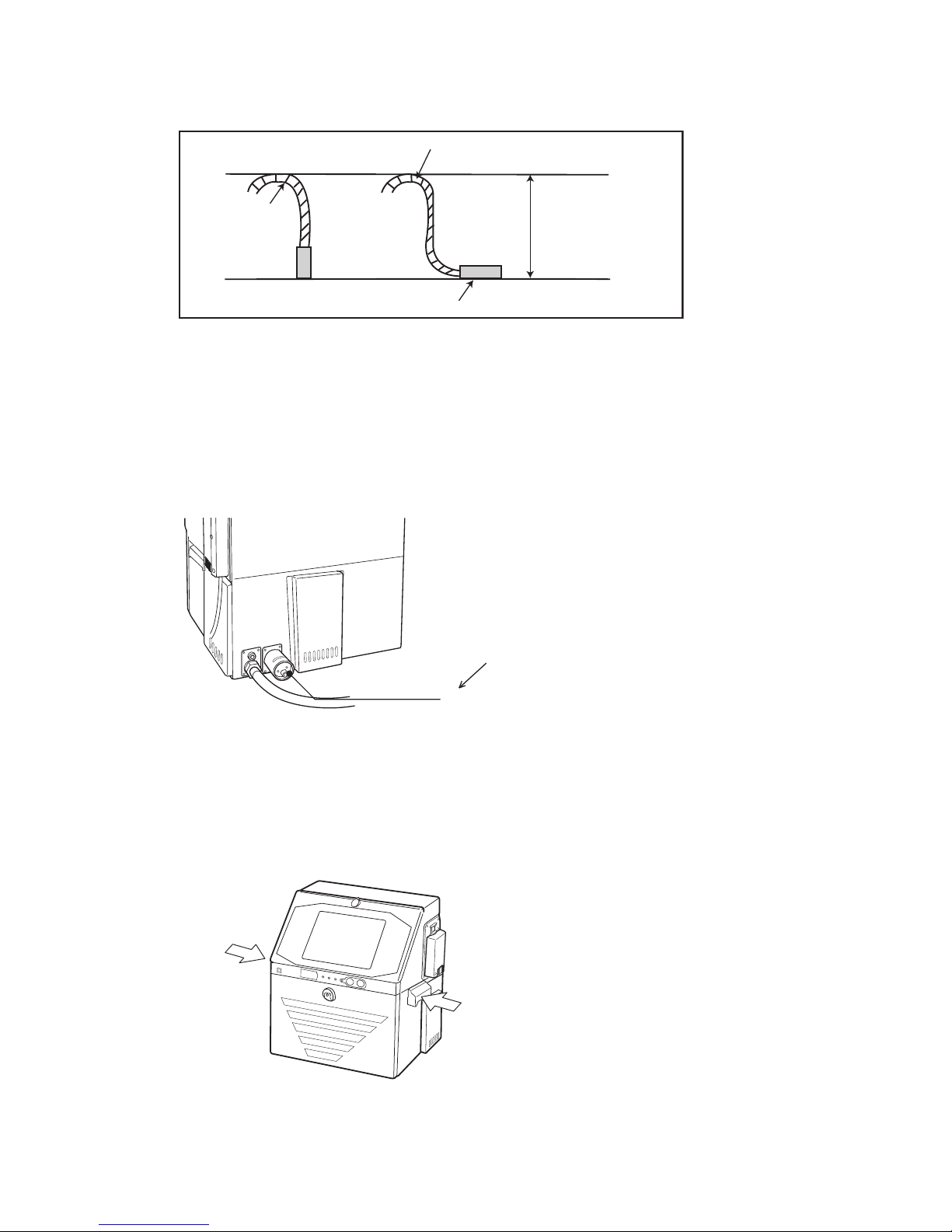
(14) If you try to fix the print head with a magnetic substance (such as iron), the cover switch will
malfunction resulting in an "Cover Open" error.
This, you must only use nonmagnetic resins or metals for fixing the print head.
(15) In the case of carrying the printer proper, use the handles in the drawing below.
Print head
Print head cable
Bend R
0.5m
Connect a duct to this port
(50 mm in diameter).
Exhaust duct
connection port
(10) When using the printer for upward or lateral printing, ensure that the rising print head cable upper end
is positioned not more than 0.5 m above the print head.
(11) If you fixed the print head, ensure that the minimum bend radius of the print head cable is at least 150 mm.
Handle the headcable with care when wiring it.
If the minimum bend radius is less than 150mm, the tubes and wires inside the headcable might be broken.
(12) The ink stream may bend for some reason or other (due, for instance, to dirt).
The facilities positioned in the direction of ink ejection should be partially covered as needed to avoid ink
accumulation.
(13) When connecting an exhaust duct to the printer, install a damper and adjust the wind velocity at the intake
port to 0.3 to 0.5 m/s. (Use an anemometer for verification. If the wind velocity is too high, the makeup
consumption increases.)
Page 30

5-1 ●Print head air purge
Printheadairpurge
connectionport
Backofbody
Pressuregauge
Pressurereducingvalve
Airsource
(cleandryair)
(capacity:Approx.1L/min)
0.1〜0.3MPa
Madeofresin.Becarefulnotto
tightentootightlywhenconnecting
withametaljoint.
5.1 Print head air purge
If the makeup remains in the electrode section after cleaning or if you use the IJ
printer at a high humidity, moisture condensation may occur within the print head,
causing leakage from the deflection electrode section. It is also important to
remember that dust or splashed ink accumulation on the deflection electrode
section may cause leakage. Performing the following air purge procedure for the
print head interior is effective in preventing such leakage.
5. INSTALLATION CHECK ITEMS
If the air-purge amount is excessive, print irregularities may occur.
After air-purge pressure adjustment, be sure to perform a printing test to
verify the printing results.
(1) Situations requiring an air purge
When the printer is used in a highly humid place such as a beer or other beverage can line
(If you use the printer in an environment in which the relative humidity is 85% or higher,
complete the print head air-purge procedure).
When a water drainage blow sequence is performed before printing.
When the printer is used in a place where a considerable amount of paper powder or other dust
exists.
When the printing distance is short so that the end of the print head is splashed with ink.
When you use inks that are indicated on the handling guidance of each ink to complete
air-purge procedure.
(2) Air-purging procedure
Introduce clean dry air into the print head air purge connection port (Rc 1/8 (PT 1/8)×screw) in
the rear of the printer main body at a pressure of about 0.1 to 0.3 MPa. If it is possible that the
employed air tanks oil or water, turn it into clean dry air with an air filter, micro-mist separator, or
the like before introducing it into the printer main body.
1
2
3
4
5
NOTICE
Max. tightening torque:1.5N m
.
Page 31
●Wiring precautions 6-1
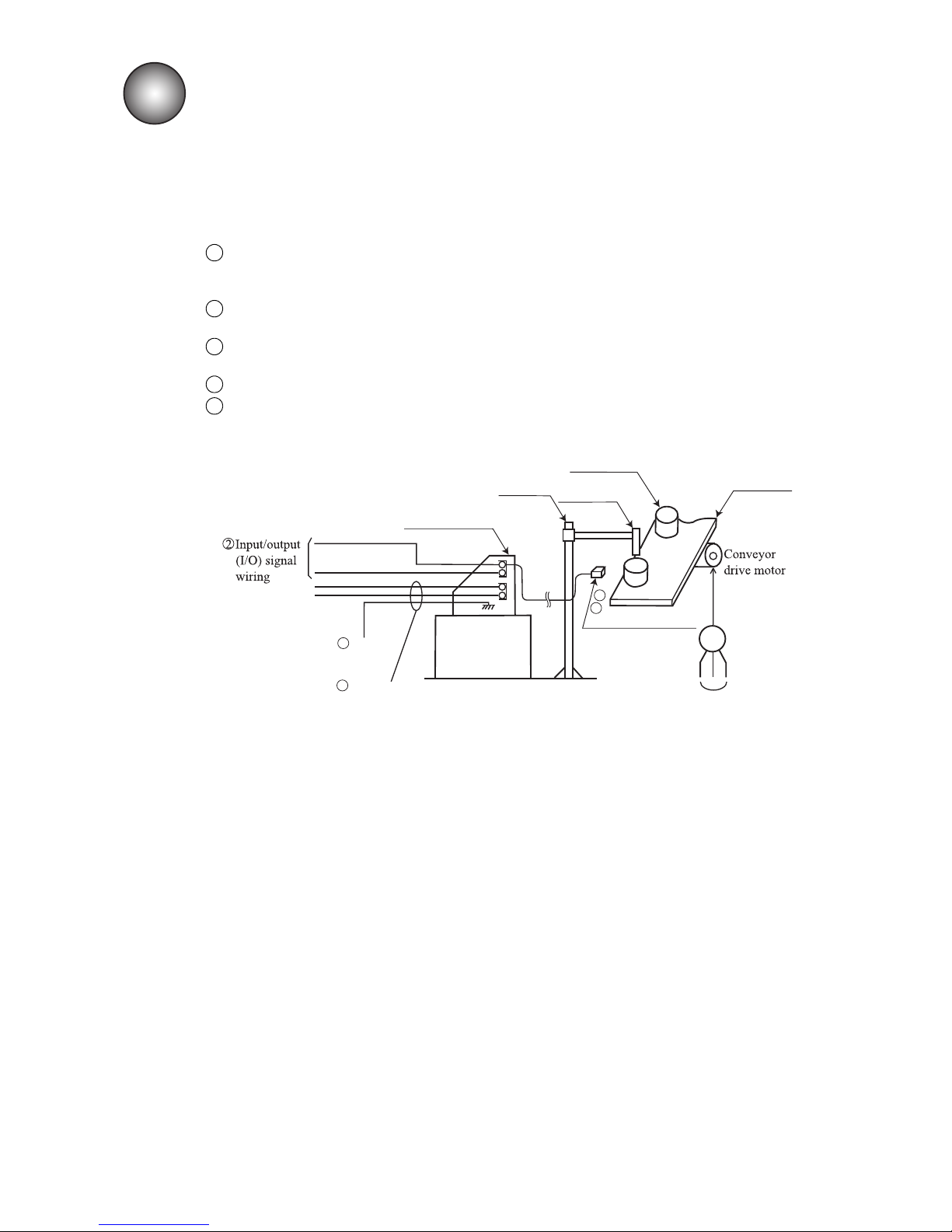
Motorpowerline
M
Conveyor
Printtargetdetector
Printhead
Printtarget
Stand
Printstop
Ready
IJprinterbody
1Primarypowersource
5Ground
3
4
6.1 Wiring precautions
(1)If noise enters the IJ printer from the outside, there is the danger of erroneous operation or trouble.
To improve noise resistance, perform wiring work as follows:
Separate the power cable to the IJ printer from other power lines for powering use (especially, power
line for a speed control inverter, etc.).
Wiring the power cable through a separate duct is even better.
Do not bundle input/output (I/O) signal wiring together with other power lines. Wire them
independently instead.
Electrically isolate the print target detector, print head, stand, and IJ printer body from other
machinery and equipment (conveyor, etc.).
Separate the print target detector wiring from other power lines.
Perform that all electrical wiring, connections and grounding comply with applicable cords.
(When erroneous operation was caused by noise, etc., use a dedicated ground.)
6. ELECTRIC SIGNAL CONNECTION
1
2
3
4
5
(2) Connection to power supply
Use a suitable plug and always connect the power source to a protective ground. In addition, arrange the
receptacles near the IJ printer so that removal is easy.
Page 32
6-2 ●Wiring precautions
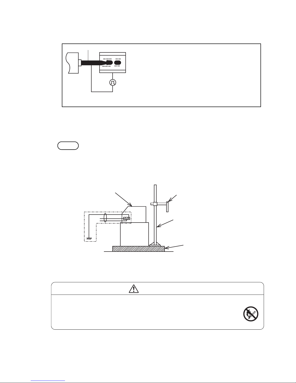
+++
+++
Signalground
Nozzle Inkcolumn
Chargeelectrode
Primarypowercable
Printheadunit
Stand(option)
Spacedbyinsulator
IJprinterbodyframe
Weldingworkcautions
E
(3) Precautions related to welding current of welder
Signal (weak electric) ground and frame ground are connected because the ink drops of the IJ printer
are electrically charged.
The ink drops are electrically charged by impressing a voltage between the charging electrode and ink column as
shown at the left.
Therefore, the ink always becomes signal ground.
In addition, since the ink is always connected to frame
ground by the clamp, etc. of the circulation path, separating
signal ground and frame ground is difficult.
Charge theory
Therefore, when a large current (for example, the welding current of a welder) flows from the
outside through frame ground, the current is also diverted to signal ground and the PC boards may
be damaged. For this reason, when performing welding work near the IJ printer, proceed as follows:
Method
Be sure to insulate the printhead and IJ printer frame to keep the welding current from flowing to
the control section of the printer, and to make a separate ground connection for the printer.
If this method is used, welding work becomes possible even while the IJ printer is operating.
●Fire is strictly forbidden around the IJ printer
The ink and makeup are both flammable. Welding sparks may cause ignition or a fire.
Take measures so that sparks do not enter the surrounding area whether or not the IJ
printer is operating, and ventilate sufficiently.
Just in case, ensure safety by installing a powder type fire extinguisher nearby.
WARNING
Page 33
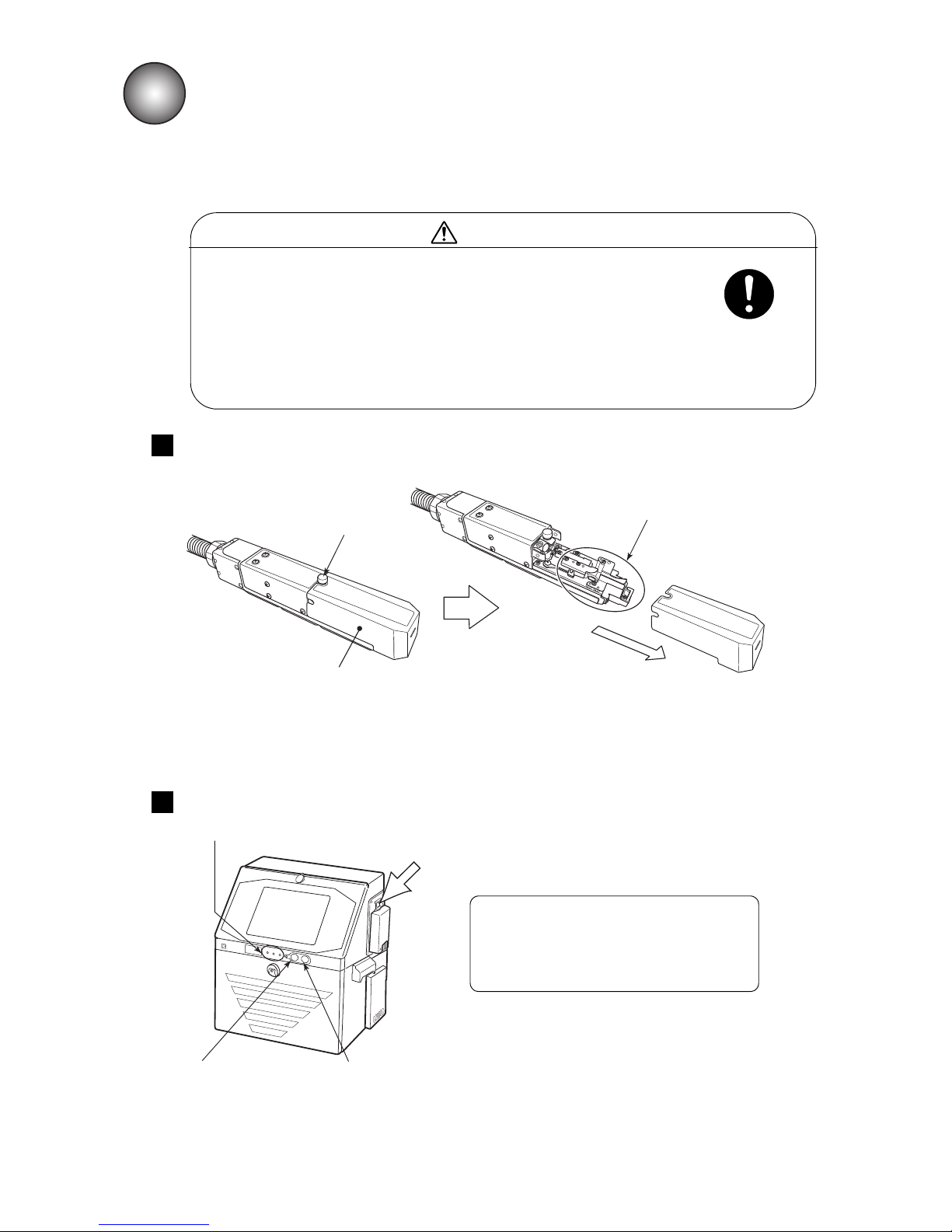
●Start operation 7-1
7.1 Start operation
7.1.1 Start operation
●The ink and makeup contains organic solvents.
When handling the ink and makeup, wear protective gloves and goggles so
that the ink will not directly contact your skin.
●An LCD touch panel is used for the screen.
Do not press the buttons with unreasonable force.
●If the system shuts down, turn off the main power switch.
To turn on the power and reuse the system, see “12. EMERGENCY
PROCEDURES”.
7. BASIC OPERATION
CAUTION
Turn on the power by pressing the main power switch.
1
Remove the print head cover, and check whether or not the print head cover and
the area around the nozzle are soiled by ink.
2
Since the IJ printer prints by ejecting ink against the print material, the outside and inside of the print
head cover are soiled by splashing of the ink from the print material. To prevent printing problems due
to soiling, check the soiling state and clean as required.
See “2.3 Print head cleaning” for a description of the cleaning method.
When stopped only by Stop switch and
the main power switch was not turned off
at the previous operation, the main power
switch does not have to be pressed
.
Loosen the screw.
Print head cover
Pull out.
Around nozzle
Operating status Indicator lamps
Stop switch
On switch
Main power switch
Page 34
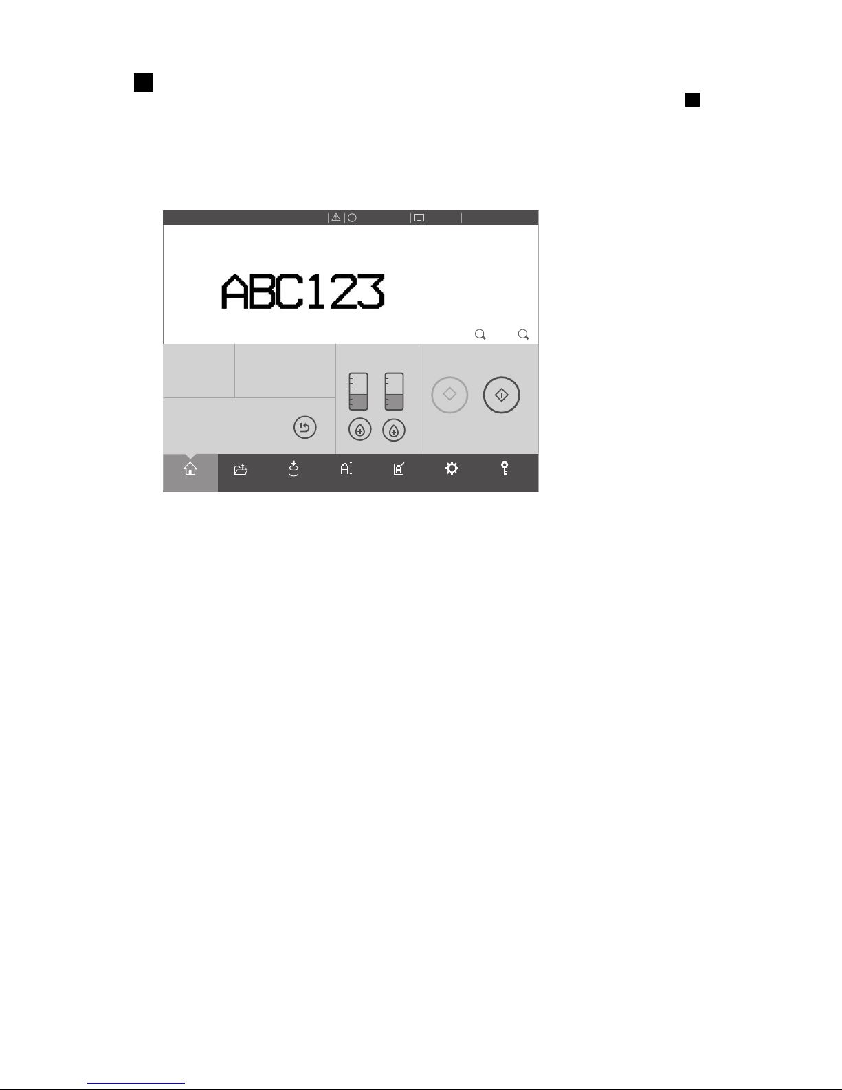
7-2 ●Start operation
Printdescription
2015.07.0712:45
SETTINGS
LOGINEDITADJUSTSAVEOPENHOME
Operating Time Ink Presure
(Standard Value:
0.255
)
100h 0.000MPa
Print Count
1.000
Makeup Ink
TEST
START PRINTING
STARTUP
100% +−
OFFLINE
STOP
ID:User2
SAMPLE 1
×
●Confirm the print description, count value, and calendar character contents.
3
Press the On switch. (Press for about 2 seconds.)
(Depending on the model, there may not be a Start switch. When the main power switch of is
pressed, the following “Print description” screen appears.)
In the case of turning on the power again, ensure that status indicator lamp is off when On switch is
pressed.
The “Print description” screen shown below appears.
If the “Select login user” screen opened, see “7.1.4 Specifying the login user”.
2
Page 35
●Start operation 7-3
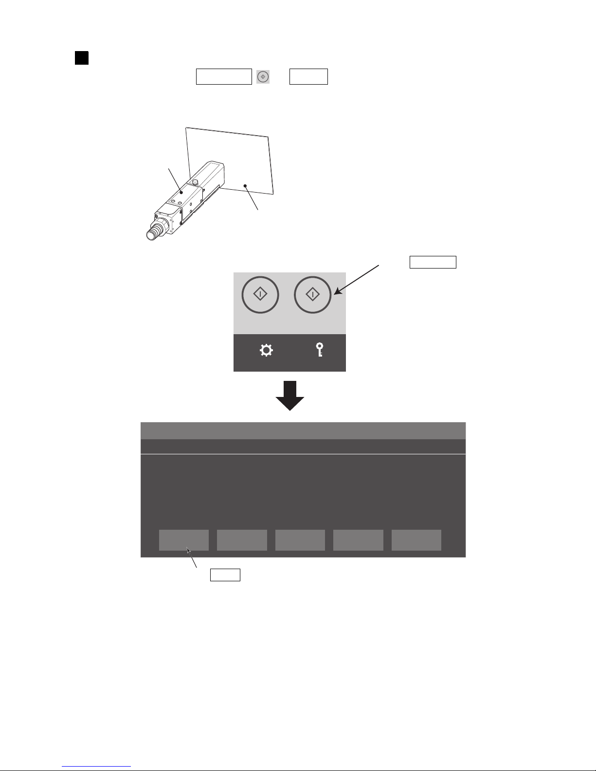
Place a piece of wiping paper, etc., against the ink injection port at the end of the print
head and press the STARTUP → Ready .
●Ink is ejected from the nozzle inside the print head.
●Place a piece of wiping paper, etc., against the ink ejection port in preparation for splashing of the ejected ink.
TEST
STARTPRINTING
STARTUP
SETTINGS
LOGIN
Ink Jet Startup Confirmation No.050
CONFIRMATION ×
The ink jet will be turned ON.
Solution 1. To change the printer status to Ready, press <Ready>.
2. To change the printer status to Standby, press <Eject ink>.
Ready CancelEject ink
4
Print head
Wiping paper, etc.
Press STARTUP .
Press Ready .
Page 36
7-4 ●Start operation
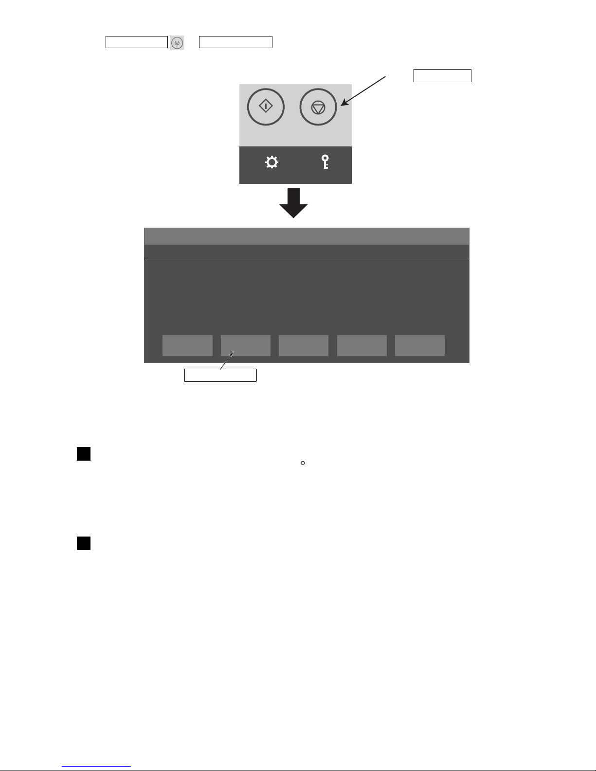
● Continuous ejection of ink even though not printing is abnormal. If this occurs, stop ink ejection by pressing the
SHUTDOWN → No-cleaning stop .
TEST
STARTPRINTING
SHUTDOWN
SETTINGS
LOGIN
Shutdown Process Confirmation No.051
CONFIRMATION ×
Shutdown will stop the ink jet.
Solution 1. To stop the ink jet, press <OK>.
2. To stop the ink without cleaning, press <No-cleaning stop>.
OK Close
No-cleaning
stop
● For a description of subsequent operation, see “7.1.2 When an error occurred at the start of operation”.
● At ink ejection, ink may momentarily spurt out and soil the paper. However, this is normal.
Press No-cleaning stop .
Press SHUTDOWN .
Wait until the status changes from “Starting” to “Ready”.
● When the temperature is low (approximately 20 C or lower), it may take longer than usual for the printer
to enter the “Ready” state.
● Check the Ink pressure.If there is a difference of 0.010 or more from the standard value, adjust the
pressure to the standard value ± 0.002. Refer to Technical manual “6.9 Adjusting tha pressure”)
5
Input the print target detection signal and check whether or not the print state and
print description are correct.
●If the print target detection signal is input when the status is “Ready”, the set print description is printed.
6
Page 37
●Start operation 7-5
7.1.2 When an error occurred at the start of operation
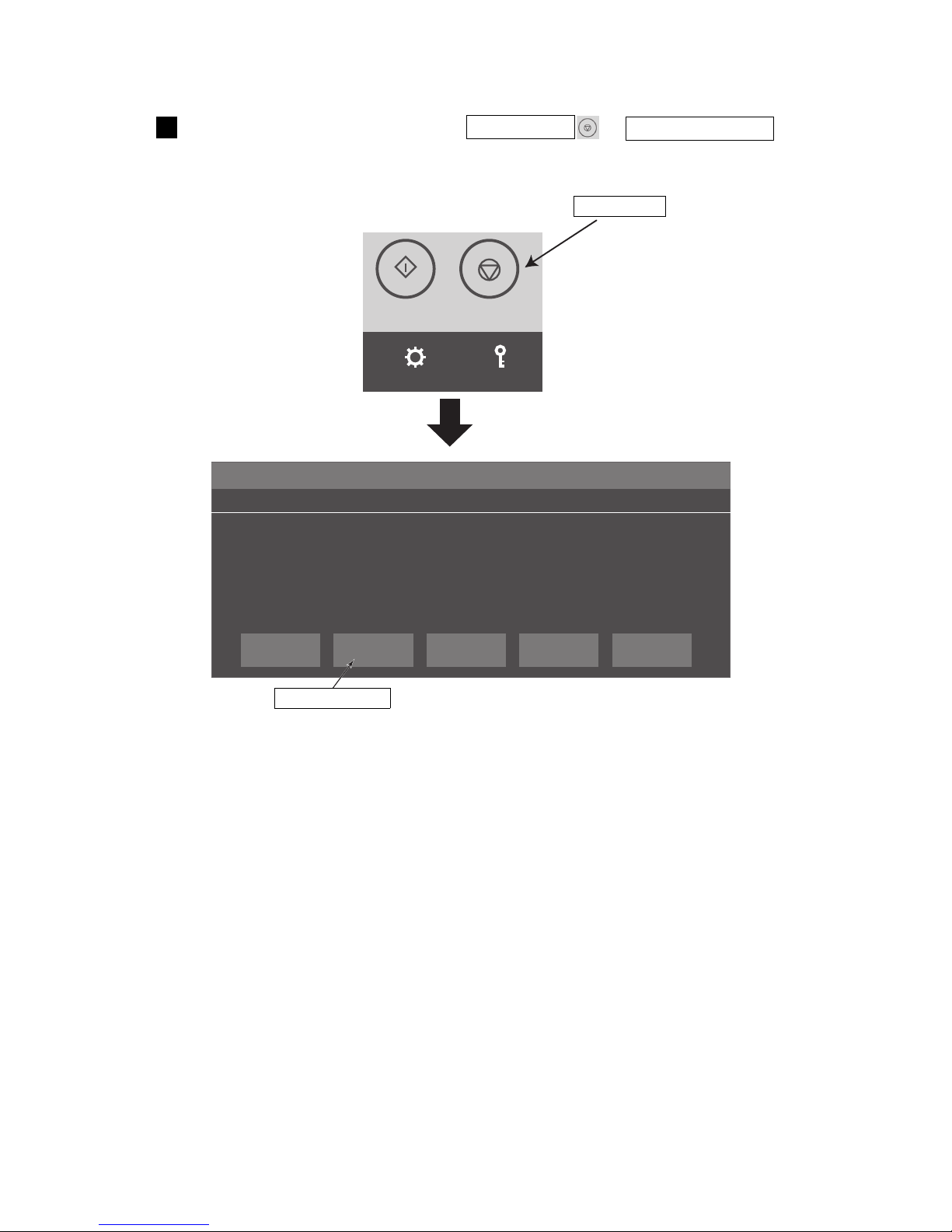
Stop ink ejection by pressing the SHUTDOWN → No-cleaning stop .1
TEST
STARTPRINTING
SHUTDOWN
SETTINGS
LOGIN
Shutdown Process Confirmation No.051
CONFIRMATION ×
Shutdown will stop the ink jet.
Solution 1. To stop the ink jet, press <OK>.
2. To stop the ink without cleaning, press <No-cleaning stop>.
OK Close
No-cleaning
stop
Press SHUTDOWN .
Press No-cleaning stop .
Page 38
7-6 ●Start operation
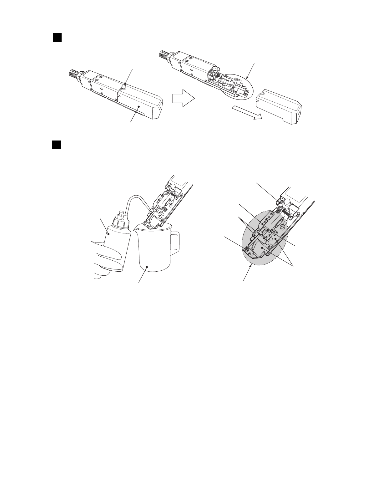
* Thoroughly wipe off the makeup on the surface of each part (including the mounting base) and dry each part
thoroughly with wiping paper.
Clean the inside of the cleaning section with makeup.
Clean the nozzle orifice, charge electrode, deflection electrode, gutter, and mounting base with makeup.
(Also see “2.3 Print head cleaning”.)
3
Loosen the screw and remove the print head cover.
2
Nozzle orifice
Charge electrode
Deflection electrode
Mounting base
Beaker
Cleaning bottle
Gutter
Area to be cleaned
Loosen the screw.
Print head cover
Pull out.
Around nozzle
Air exhaust port
Page 39
●Start operation 7-7
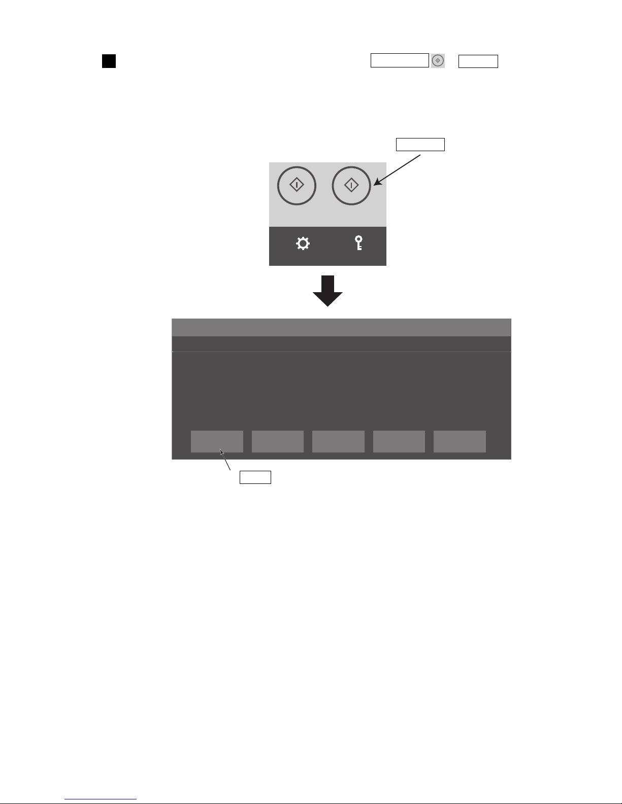
TEST
STARTPRINTING
STARTUP
SETTINGS
LOGIN
Ink Jet Startup Confirmation No.050
CONFIRMATION ×
The ink jet will be turned ON.
Solution 1. To change the printer status to Ready, press <Ready>.
2. To change the printer status to Standby, press <Eject ink>.
Ready CancelEject ink
With the print head cover removed, press the STARTUP → Ready .
● Ink is ejected from the nozzle. (The status changes from “Stop” to “Starting”.
● Operate the unit with the end of the print head remaining inside the beaker.
4
Press STARTUP .
Press Ready .
Page 40
7-8 ●Start operation
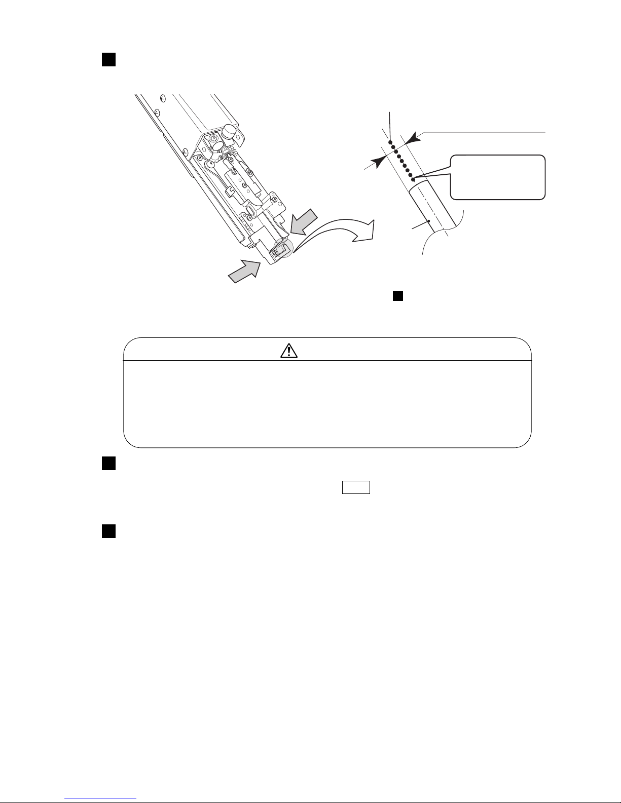
Confirm that the ink stream is at the center of the gutter.
● Check the position of the ink stream from the sides and top of the print head as shown in the figure
and confirm that it is in the center of the gutter.
5
● Wear protective gear (goggles and mask) when checking the position of the ink stream.
● If you should get ink or makeup in your eyes or mouth, immediately wash with warm
water or water and see a doctor.
● When ejecting the ink, do it after confirming that there is no one in the ejection
direction.
(Operate with the end of the print head inserted in a beaker, etc.)
WARNING
Install the print head cover.
●Wait until the status changes to “Ready”.
●If the “Cover open” error was displayed, press the Close .
6
Input the print target detection signal and check the printing state.
(See “3.1.1 Start operation”.)
7
Gutter
Ink stream
Side direction
Upper direction
Gutter entrance diameter
The ink stream
should be positioned
at the center of the
gutter inlet.
● If the ink stream is not at the center of the gutter, perform step and stop the ink injection. After
that, take action in accordance with Technical Manual “6.4 How to correct ink stream bending and
nozzle clogging”.
1
Page 41
●Start operation 7-9
TEST
STARTPRINTING
STARTUP
SETTINGS
LOGIN
Ink Jet Startup Confirmation No.050
CONFIRMATION ×
The ink jet will be turned ON.
Solution 1. To change the printer status to Ready, press <Ready>.
2. To change the printer status to Standby, press <Eject ink>.
Ready CancelEject ink
Use this procedure when you want to eject ink from the nozzle for a purpose other than printing.
(Use only during maintenance. To print, press the STARTUP → Ready .
Press the STARTUP → Eject ink .
Ink ejection for maintenance
● Operation can be aborted by pressing the Cancel at the “Ink Jet Startup Confirmation message”.
● If the print head cover installed, the printer will not enter the Ready state even if this operation is
performed. (Enters the Standby state)
Press Eject ink .
Press STARTUP .
Page 42
7-10 ●Start operation
Print Abort Confirmation No.184
CONFIRMATION ×
Printing will be aborted.
Solution Press <OK> to abort.
OK Cancel
Print description
2015.07.0712:45
SETTINGS
LOGINEDITADJUSTSAVEOPENHOME
Operating Time Ink Presure
(Standard Value:
0.255
)
1,234
h
0.000
MPa
Print Count
0
Makeup Ink
TEST
START PRINTING
SHUTDOWN
100%
+−
OFFLINE
READY
ID:User2
SAMPLE 1
7.1.3 Ready and Standby state switching operation
(1) “Ready” state → “Standby” state switching
● With the conveyor interlock being activated by “Ready” signal, should this “Ready” signal be
turned to “Standby”, the conveyor will stop.
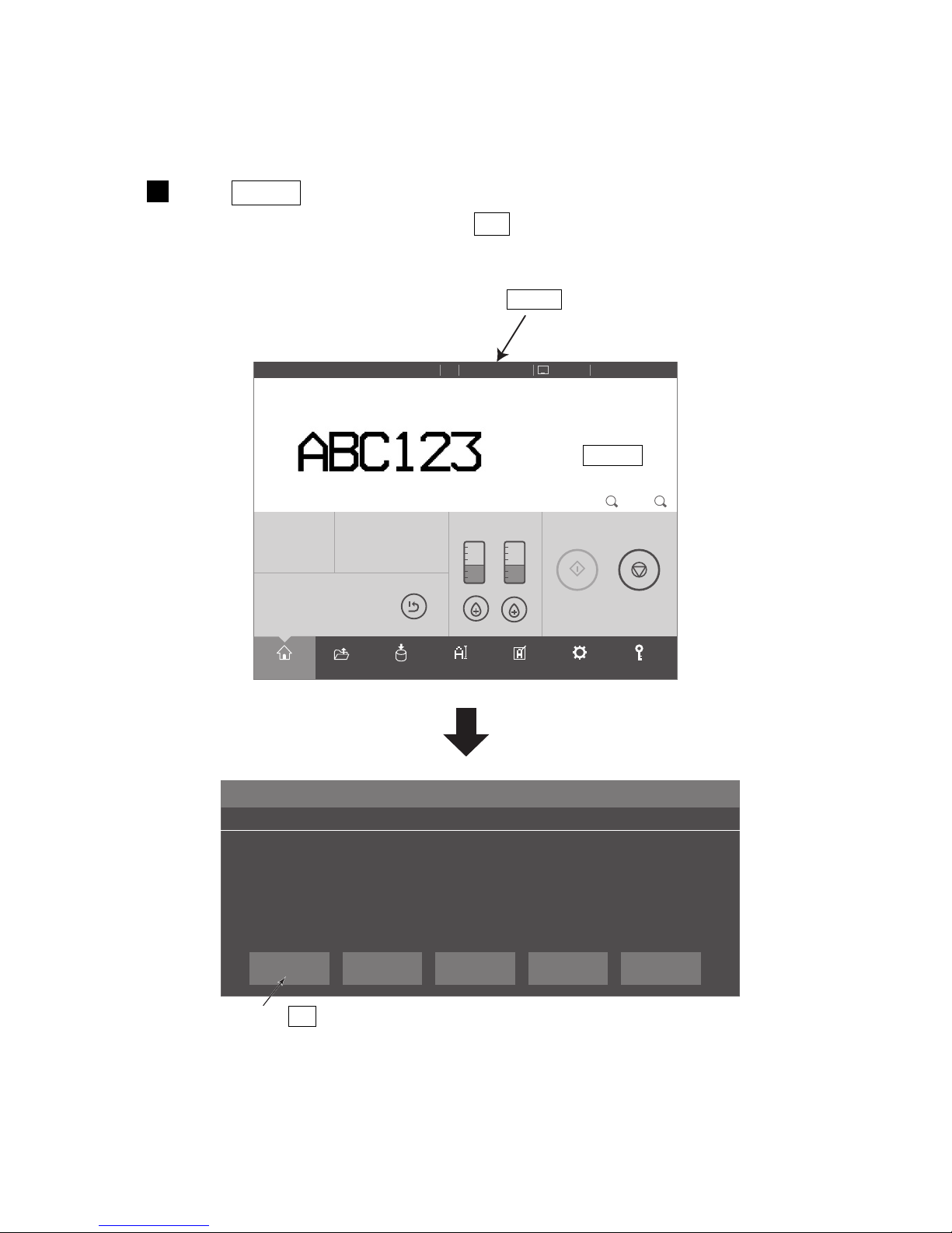
Press READY on the upper of the screen, and the message "Print Abort
Confirmation" appears. Then press OK .
1
Press READY .
Press Standby .
Press OK .
Page 43
●Start operation 7-11
+
Print description
2015.07.0712:45
SETTINGS
LOGINEDITADJUSTSAVEOPENHOME
Operating Time Ink Presure
(Standard Value:
0.255
)
1,234
h
0.000
MPa
Print Count
0
Makeup Ink
TEST
START PRINTING
SHUTDOWN
100%
−
OFFLINE
STANDBY
ID:User2
SAMPLE 1
Print Confirmation No.183
CONFIRMATION ×
The newly created print data will be printed.
Solution Press <OK> to print.
OK Cancel
(2) “Standby” state → “Ready” state switching
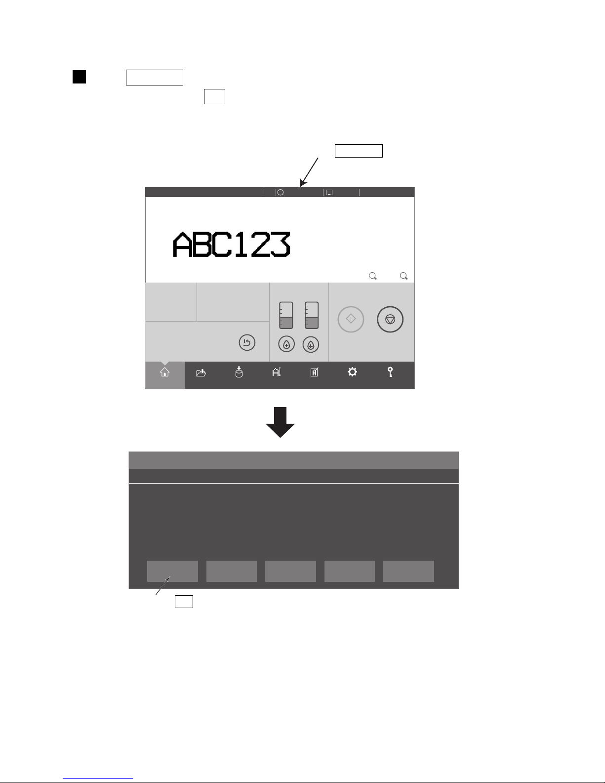
Press STANDBY on the upper of the screen, and the message "Print Confirmation"
appears. Then press OK .
1
Press OK .
Press STANDBY .
Page 44
7-12 ●Start operation
Selectloginuser
2015.07.0712:45
OFFLINE
STOP
×
admin
admin4
user7
user2
user5
admin8
admin6
user3
Enter
7.1.4 Specifying the login user
(1) Functions
●Specifies the user to be logged in at power-on.
●Selects the user and inputs the password when logging in.
●The administrator defines the user name and password and password protection setting in advance.
The password protection setting can be changed beforehand for each user. The user name must be within
12 digits.
●Sets whether or not to select a user which logs in when the power is turned on.
See the Technical Manual “3.3 Selecting login user when power is turned on”.
(2) Operation
The administrator sets the login procedure necessary at power-on beforehand.
Selectloginuser
2015.07.0712:45
OFFLINE
STOP
×
admin
admin04
user07
user2
user05
admin08
admin06
user3
Q
A
Aa Z X C V B N M
S D F G H J K L
W E R T Y U I O P 4
7 8 9
5 6
102 3
Enter
×
×
Password
Turn on the power.
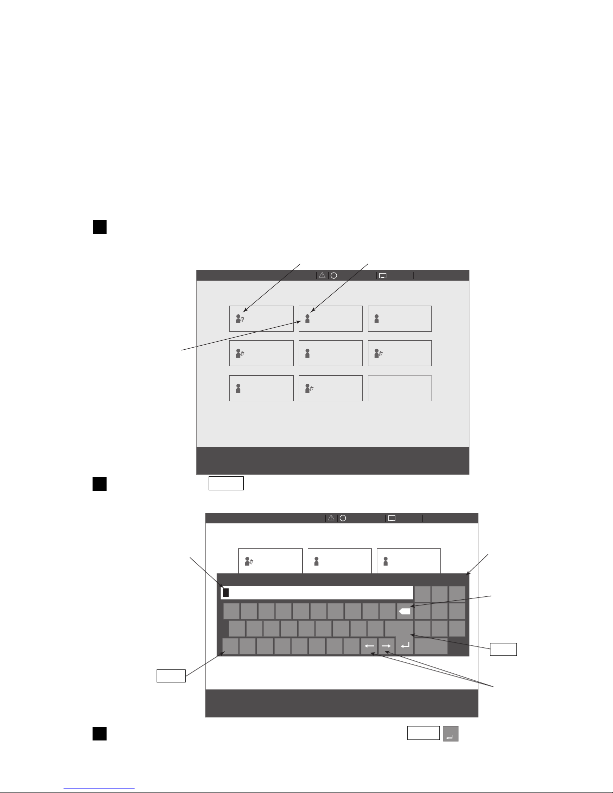
The Select login user screen is displayed.
1
Press user name user2 .
A password input window opens.
2
Input the password for user name “user2” and press Enter .
The initial screen is displayed.
3
The saved user
names are
displayed.
The password input
window opens.
Enter
This icon shows "Administrator".
This icon shows "User"
The window
will close.
Back space
Cursor
Shift
Page 45
●Shut down operation 7-13
7.2 Shut down operation
7.2.1 Automatically stopping by pressing one button
(UX-D,E only)
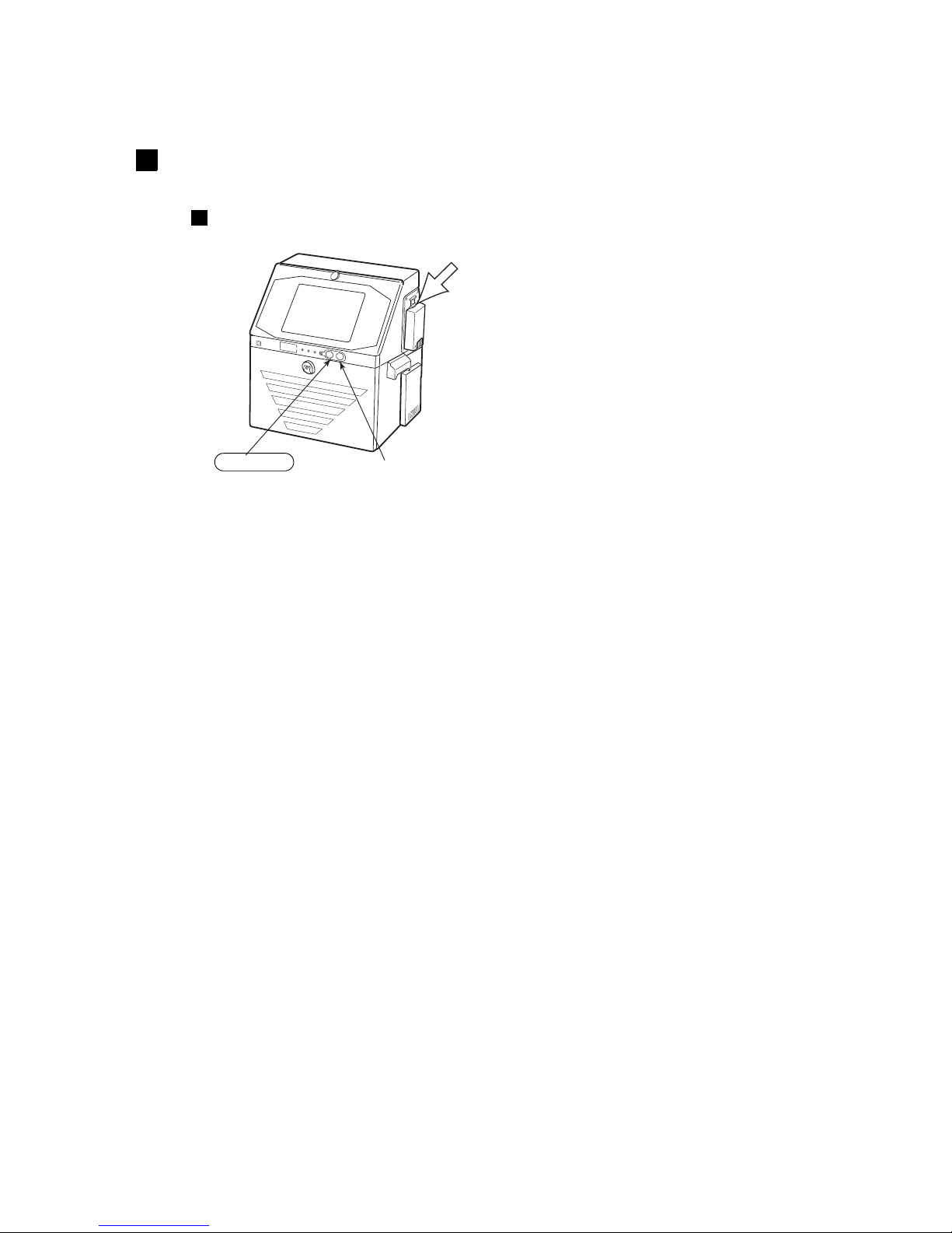
The power is turned OFF by Stop switch from the state in which ink is being ejected or being stopped.
(The main power switch does not have to be turned off. The power consumption does not change even
if the main power switch remains ON.)
Main power switch
On switch
Stop switch
Press the Stop switch. (Press for about 2 seconds.)
All operations up to IJ printer power OFF are performed automatically.
Depending on the model, there may not be a Stop switch. Stop the ink with the button on the screen
at of par. 7.2.2, and turn off the power in accordance with par. 7.2.3.
1
1
Page 46
7-14 ●Shut down operation
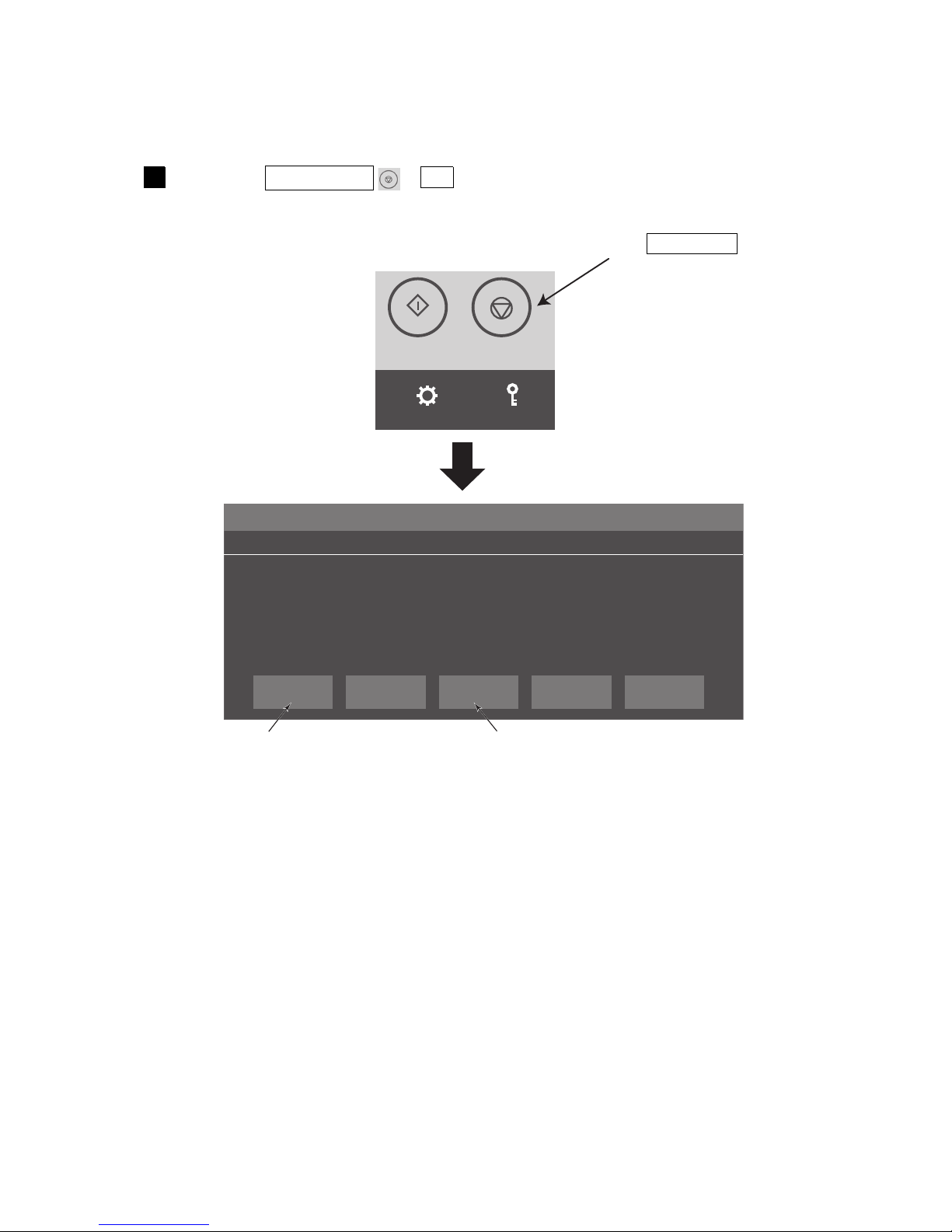
7.2.2 Stopping ink ejection by pressing the screen button
● Perform ink stop processing using the following procedure.
(1) UX-D,E
TEST
STARTPRINTING
SHUTDOWN
SETTINGS
LOGIN
Shutdown Process Confirmation No.052
CONFIRMATION
×
Shutdown will stop the ink jet.
Solution 1. To stop the ink jet, press <OK>.
2. To stop the ink without cleaning, press <No-cleaning stop>.
3. To execute the auto power shutdown process after ink stop.
press <STOP>.
OK CloseSTOP
No-cleaning
stop
Press the SHUTDOWN → OK .
A confirmation screen is displayed.
1
●Wait for the status to change from “Stopping” to “Stop”.
Press SHUTDOWN .
Stops ink jet.
Turns OFF the power after ink jet is stopped.
Page 47
●Shut down operation 7-15
TEST
STARTPRINTING
SHUTDOWN
SETTINGS
LOGIN
Shutdown Process Confirmation No.051
CONFIRMATION ×
Shutdown will stop the ink jet.
Solution 1. To stop the ink jet, press <OK>.
2. To stop the ink without cleaning, press <No-cleaning stop>.
OK Close
No-cleaning
stop
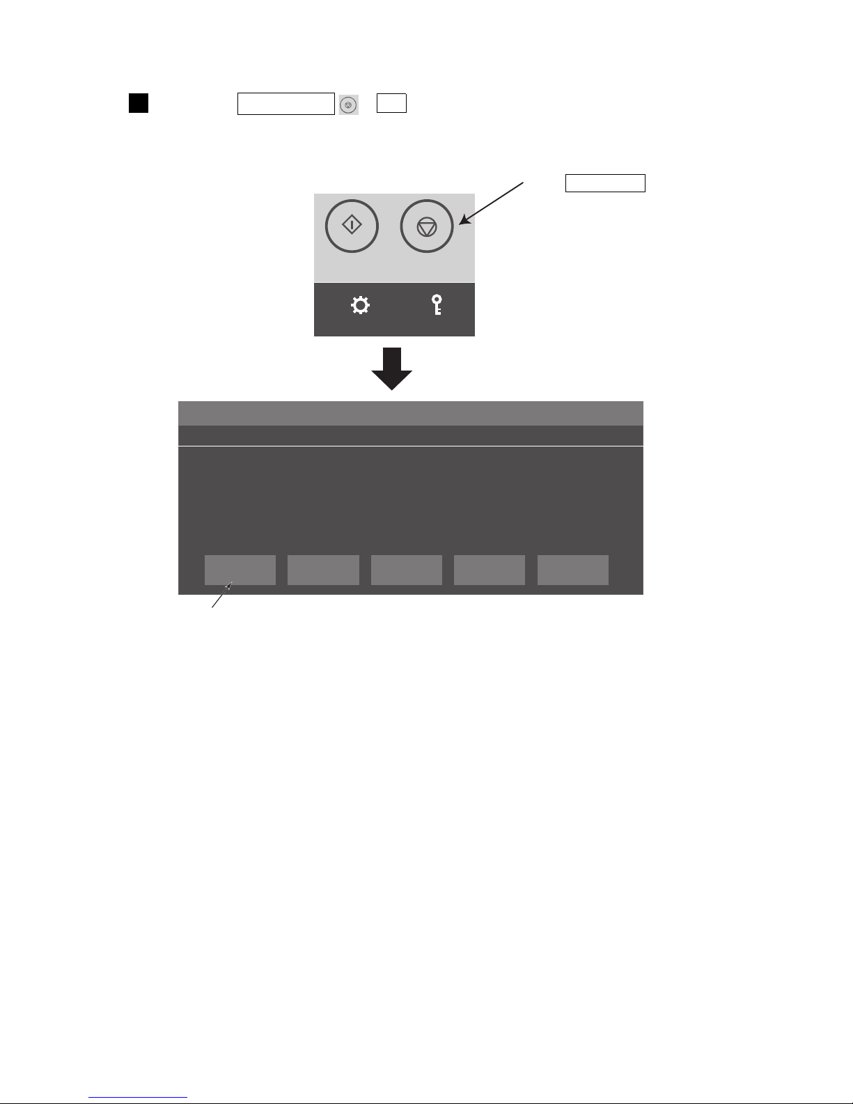
(2) UX-B
●Wait for the status to change from “Stopping” to “Stop”.
Press SHUTDOWN .
Press the SHUTDOWN → OK .
A confirmation screen is displayed.
1
Stops ink jet.
Page 48
7-16 ●Shut down operation
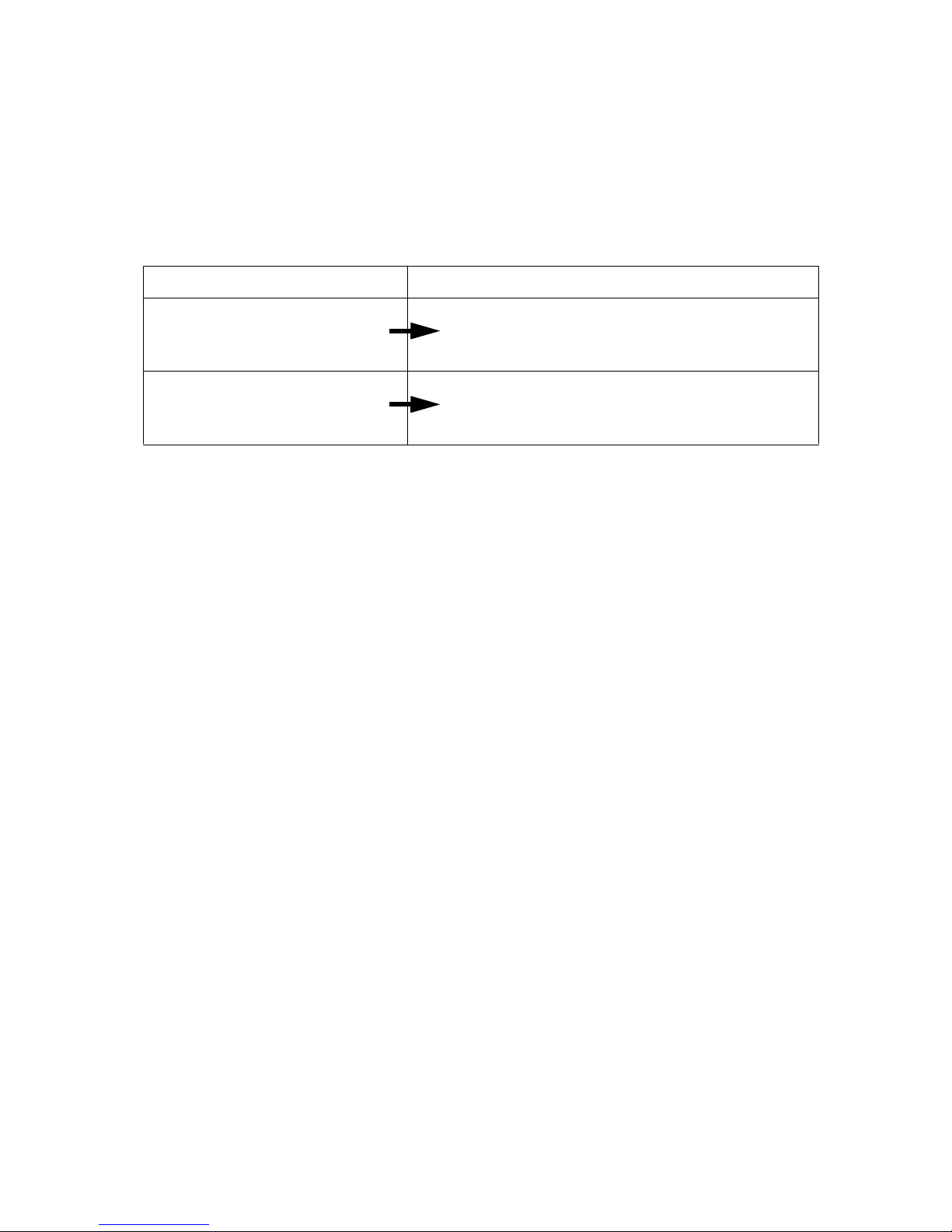
Turn off method Method which displays a screen at the next operation
When the main power switch was
turned off after being stopped by
Stop switch.
Screen is displayed when the startup switch is
turned ON after the main power switch was turned
ON.
When the main power switch was
turned off without using the stop
switch
Screen is displayed when the main power switch
is turned ON.
7.2.3 Turning off the main power switch
(1) UX-D,E
●Press Stop switch normally instead of main power switch to turn off the power at the end of operation.
●If the IJ printer will not be used for a long time, turn off the main power switch.
●Do not turn off the main power switch while ink is being ejected.
See “11. EMERGENCY PROCEDURES”.
●The state when the power is turned on at the next operation differs depending on the state when the main
power switch was turned off.
(2) UX-B
●Turn off main power switch at the end of operation.
●Do not turn off the main power switch while ink is being ejected.
Page 49
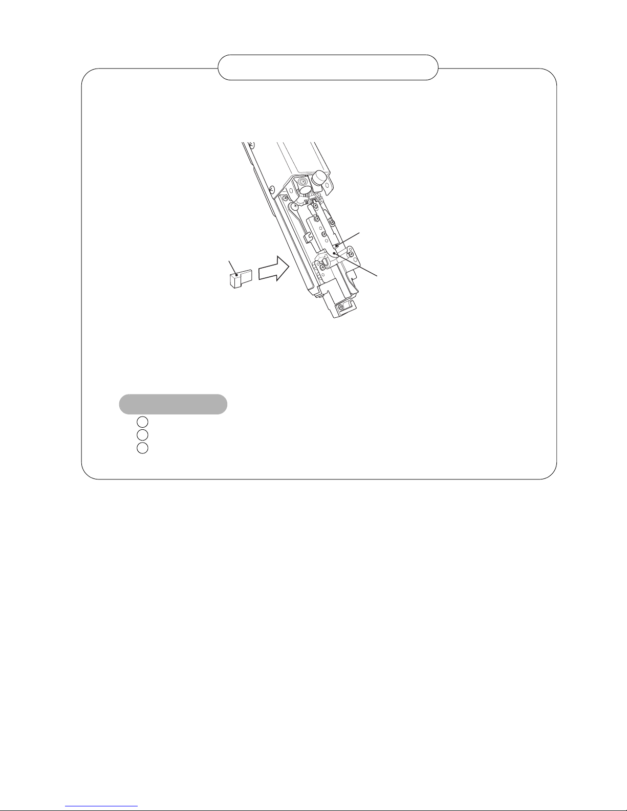
●Shut down operation 7-17
1. To prevent drying of the nozzle orifice and dust from sticking to the plate during unit storage,
the unit is shipped with a “nozzle rubber seal” installed. Remove this “nozzle rubber seal” at
installation and test running and adjustment.
2. The “nozzle rubber seal” prevents drying of the nozzle orifice and dust from sticking to the
plate. When the IJ printer will not be used for several days over a holiday, etc., we
recommend that the “nozzle rubber seal” be installed between the nozzle orifice and charge
electrode at shutdown.
Store the “nozzle rubber seal” in a plastic bag, etc., to protect it from dirt and dust.
Always install the “nozzle rubber seal” after cleaning it with makeup.
When installing the “nozzle rubber seal”, be careful not to deform the charge
electrode.
1
2
3
Usage precautions
Handling the nozzle rubber seal
Charge electrode
Nozzle orifice
Nozzle rubber seal
7.2.4 Careful Cleaning
(1) Overview
● This is the function to clean the printer carefully when IJ Printer is frequently used in high-temperature
environment, or before the weekend, such as 2-3 day shutdown period. This careful cleaning uses more
amount of makeup than the normal cleaning.
● Please note that precautions shall be fully understood when using this function, because with the
“Careful-Cleaning” function, IJP uses more amount of makeup than the normal Cleaning Stop.
(2) How to use Careful Cleaning function
● Please contact your nearest local distributor to use this function.
Page 50
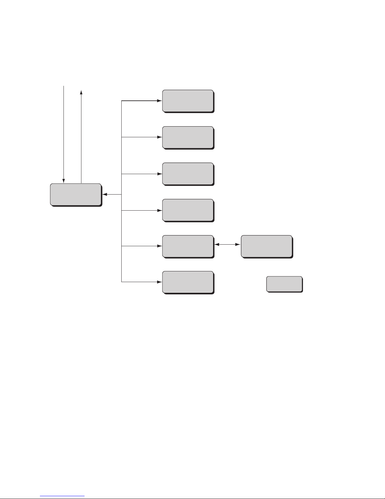
7-18 ●Basic operation
7.3 Basic operation
7.3.1 Operating Scheme (New HMI)
Power ON Power OFF
SETTING
SAVE
ADJUST
EDIT
LOGIN
: Screen name
OPEN
* The new HMI screens can move directly to other displays without going back to HOME screen.
* "Ink eject" and "Ink stop" can operate only when HOME screen is displayed.
* Please refer to "7.3.3 Change procedure of (New HMI)
⇔ (Previous HMI)" for the change procedure of the
operation scheme (New HMI) and (Previous HMI).
HOME
(Print description)
Calibration
touch screen
coordinates
Page 51
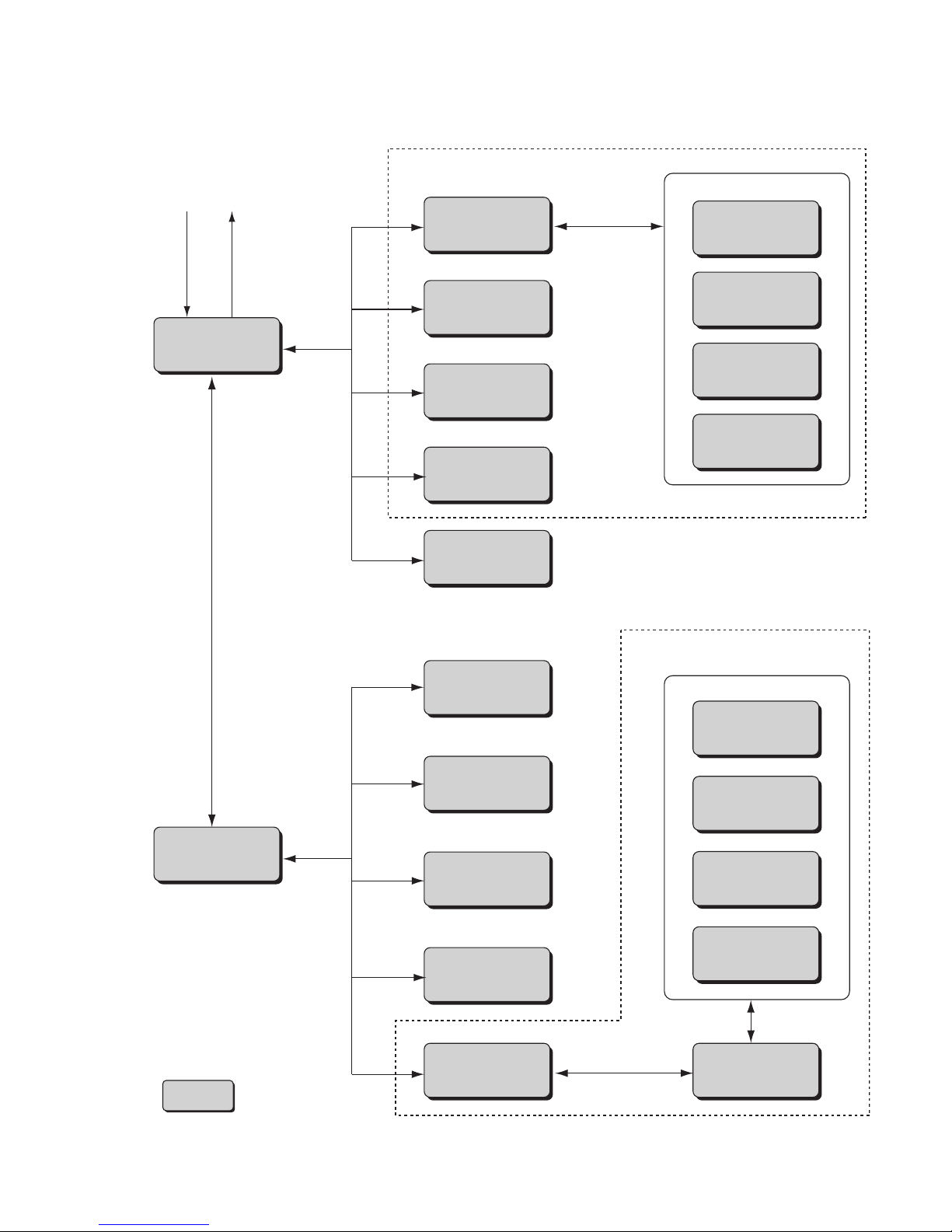
●Basic operation 7-19
Print description
(Menu 1)
Print description
(Menu 2)
Power ON Power OFF
Operation
management
Select message
Over Write
message
Adjust print
parameters
Environment setup
menu
Auxiliary function
menu
Maintenance
menu
: Screen name
* See next page, Change message
Change message
Edit message
Print format
Print specifications
Change message
Adjust print
parameters
Edit message
Print format
Print specifications
Adjust print
parameters
Change message
Select
login user
Create/Edit
message
For print target data
For save data
Change message
7.3.2 Operating Scheme (Previous HMI)
(1) Overall view
Page 52
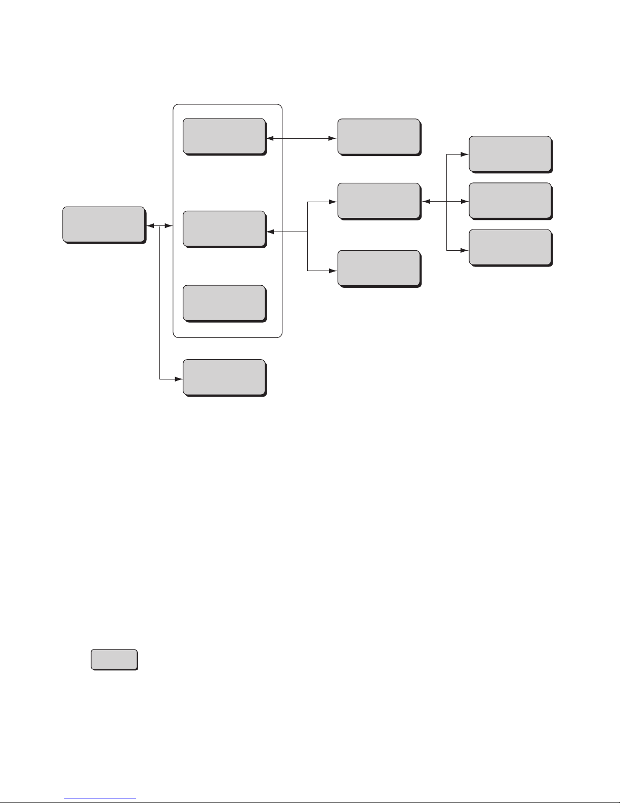
7-20 ●Basic operation
(2) Change message
Change message
Edit message
Print format
Print specifications
Var i ous prin t
setup
Count conditions
Calendar
conditions
Adjust
Inter-character
space Substitution
rules
Shift code setup
(Op on UX-D,E)
(Op on UX-D,E)
Time count
conditions
* The display can be
switched between screens
Edit message,
Print format, and
Print specifications.
: Screen name
Page 53
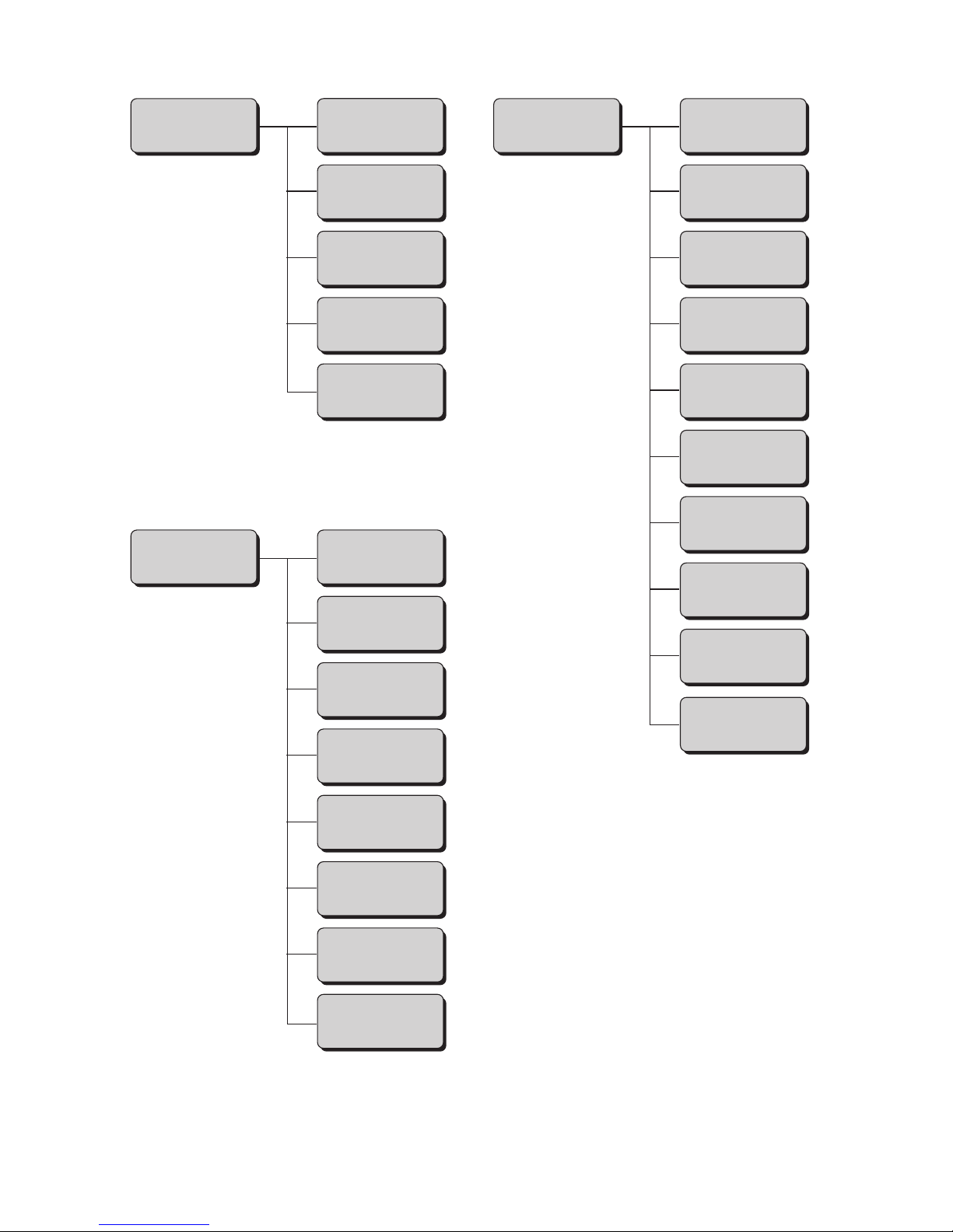
●Basic operation 7-21
(3) Environment setup menu, Auxiliary menu, Maintenance menu
Environment setup
menu
Auxiliary function
menu
Maintenance
menu
User environment
setup
Date / time
setup
Communication
environment
setup
Touch screen
setup
Login
management
Manage
messages / Group
Create
user pattern
Calibration touch
screen coordinates
Copy data
(IJP → USB)
Copy data
(USB → IJP)
Edit standard
pattern
Edit substitution
rules
Select languages
Unit information
Operation
management
Tes t p ri n t
Excitation
V update
(Nozzle test)
View alarm
history
Circulation control
View software
version
Comm. monitor
(Optional on UX-B)
Password
protection
Solenoid valve/
pump test
(Optional on UX-B)
Page 54
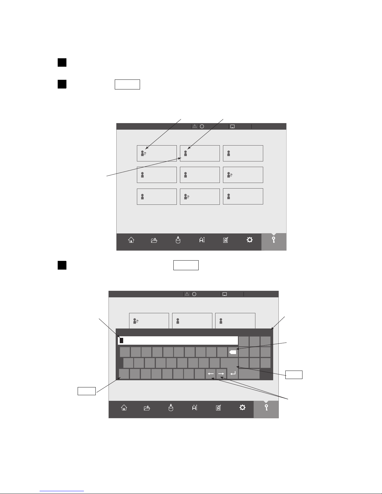
7-22 ●Basic operation
Selectloginuser
2015.07.0712:45
OFFLINE
STOP
×
admin
user4
user7
user2
user5
admin8
admin6
user3
CurrentUserID:user9
user9
SETTINGS
LOGINEDITADJUSTSAVEOPENHOME
Selectloginuser
2015.07.0712:45
OFFLINE
STOP
×
admin
admin04
user07
user2
user05
admin08
admin06
user3
Q
A
Aa Z X C V B N M
S D F G H J K L
W E R T Y U I O P 4
7 8 9
5 6
102 3
Enter
×
×
Password
CurrentUserID:user9
SETTINGS
LOGINEDITADJUSTSAVEOPENHOME
⇔
The new HMI screen is displayed.
1
Press menu LOGIN .
The Select login user screen will be displayed.
2
The saved user
names are
displayed.
This icon shows "Administrator".
This icon shows "User"
Press the administrator name admin .
A password input window opens.
3
The password input
window opens.
Enter
The window
will close.
Back space
Cursor
Shift
7.3.3 Change procedure of (New HMI) (Previous HMI)
(1)Change procedure of (New HMI) ⇒ (Previous HMI)
Page 55
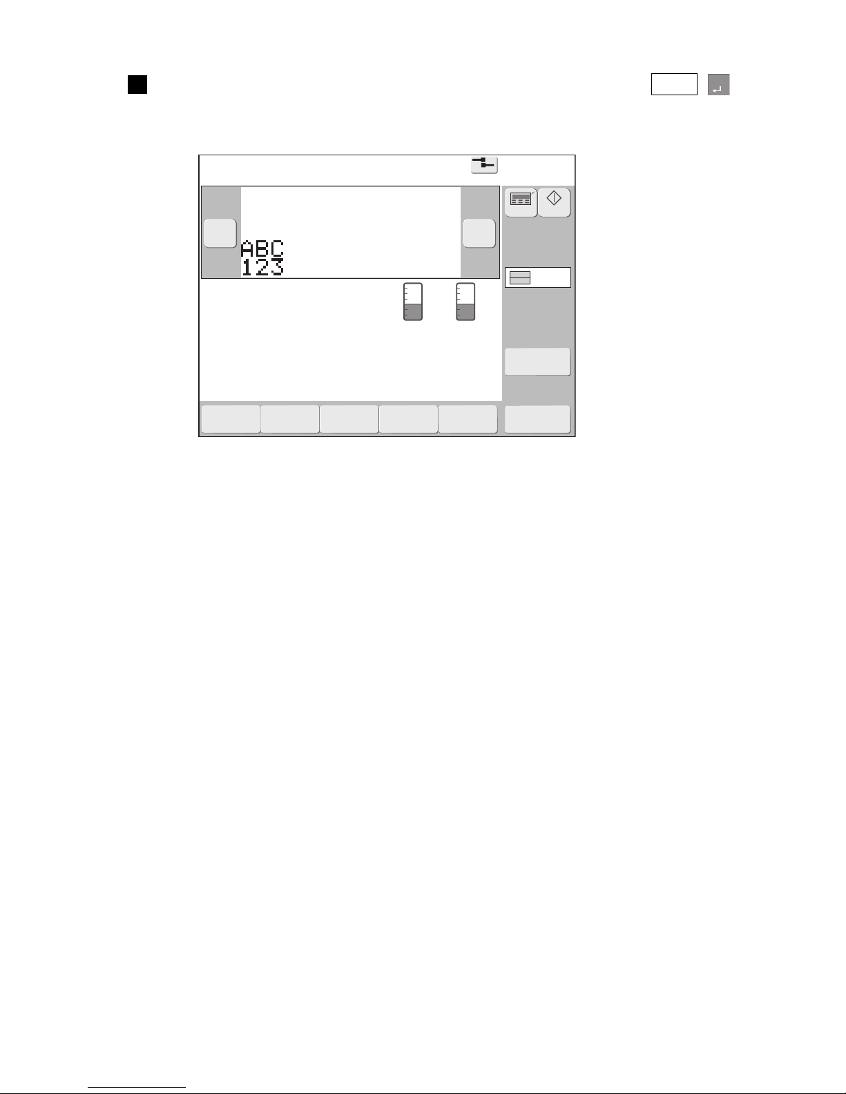
●Basic operation 7-23
Print description
2015.07.0712:45
Menu
Com=0
[Stop ]
Ink operating time 100(hours)
Cumulative op. time 100(hours)
Print count 1000(prints)
Ink pressure 0.000(MPa;standard value:0.255)
Change
message
Select
message
Overwrite
message
Adjustprint
parameters
Operation
management
Message name[ ]
− +
Current user ID : admin
Interlaced
Printcount
reset
Startup
Manual
Makeup Ink
Enter
Input the password for the administrator name "admin" and press Enter .
Logs in again using administrator name "admin" and the touch screen returns to the Print description
screen (Previous HMI) is displayed.
4
Page 56
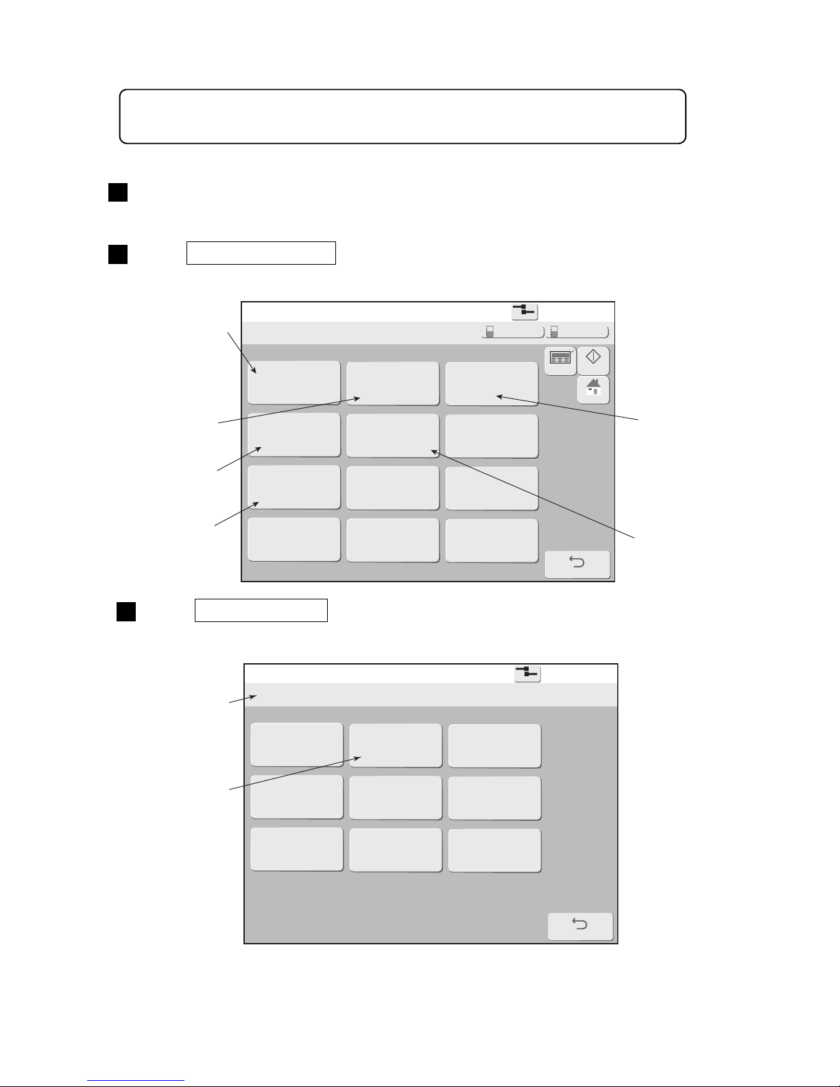
7-24 ●Basic operation
The previous HMI screen is displayed.
1
(2)Change procedure of (Previous HMI) ⇒ (New HMI)
Login management menu
2015.07.0712:45
Back
Com=0
[Stop ]
Login history Select login user Password setup
User conditions
setup
Create new User ID
Using environment
setup
Delete User ID
HOME
Startup
Manual
Makeup Ink
Select login user
2015.07.0712:45
Back
Com=0
[Stop ]
admin user2 user3
user4
user5 user6
user7 user8 user9
Current user ID : user9
Press Login management in the environment setup menu.
The Login management menu is displayed.
2
Press Select login user .
The Select login user screen is displayed.
3
Displays the
history of
logged in
users.
Select login
user
Set the password.
However, it is not
displayed when
authorization is not
given from the
administrator.
The user ID currently
logged in is displayed.
The saved user
name is displayed.
Conditions
setup
New user ID
create
Environment setup
Setup on “Touch screen setup” is necessary to display the New HMI screens.
For details, refer to Technical Manual "3.5 Human Machine Interface [HMI] setup".
Page 57
●Basic operation 7-25
Select login user
2015.07.0712:45
Back
Com=0
[Stop ]
admin user3
User4
User5 User6
User7 User8 User9
←
Cancel
Enter
→
A B C D E F G H I J
K L M N O P Q R S T
123
U V W X Y Z
Delete
Change Change
ABC
user2
Current user ID : user9
Enter
Printdescription
2015.07.0712:45
SETTINGS
LOGINEDITADJUSTSAVEOPENHOME
Operating Time Ink Presure
(Standard Value:
0.255
)
100
h
0.000
MPa
Print Count
1.000
Makeup Ink
TEST
START PRINTING
STARTUP
100% +−
OFFLINE
STOP
ID:User2
×
Press user name user2 .
A password input window opens.
Caution : Administrator user can't change to New HMI screens.
4
Enter the password of user name “user2”, and press Enter .
Logs in again using user name "user2" and the touch screen returns to the Print description
screen (New HMI) is displayed.
5
Inputs the password
of user name "user2".
Enter
Page 58
8-1 ●Ink and makeup replenishment
● When replenishing the ink and makeup, changing the ink, or performing other work in
which the ink and makeup are handled, be sure not to spill the ink and makeup.
If the ink and makeup is accidentally spilled, quickly wipe it off with wiping paper, etc.
Do not close the maintenance cover until you verify that the wiped parts are
completely dry.
Since the ink and makeup vapor will collect inside the printer especially in the state in
which the ink and makeup was spilled inside the printer and was not wiped off
completely, it will cause ignition and fire.
When wiping is difficult in the energized state, perform shutdown processing with the
maintenance cover remaining open and turn off the power, then perform wiping
again.
● If leaking of the ink and makeup inside the printer was detected during printer
operation or maintenance, quickly wipe it with wiping paper, etc. and perform
shutdown processing with the maintenance cover remaining open and turn off the
power, then repair the leak.
If operation is continued when the ink and makeup is leaking, it will cause trouble
and prevent normal printing will become.
In addition, since the ink and makeup are combustible, they may cause a fire.
● The ink and makeup, their waste solution, used wiping papers and empty containers
are flammable. Waste disposal must comply with appropriate regulations.
Consult the appropriate regulatory agency for further information.
● When the ink particles are caught in a beaker during test printing, etc., use a
conductive beaker and securely connect the beaker to a ground.
In addition, be sure that the print head is not inserted into the beaker.
Since the ink particles used in printing are electrically charged, if the beaker is not
connected to a ground, the charge load will gradually increase and cause a fire.
8. INK AND MAKEUP
REPLENISHMENT
● Never pour the ink and makeup waste into a sewer, etc.
Have the ink and makeup drainage processed by an industrial waste processor as
special control industrial waste and used wiping papers and the empty container as
industrial waste.
● Do not remove, apply unreasonable force to, or bend the piping tubes unnecessarily.
Since high pressure is applied to parts of the ink and solvent inside the piping tube,
the ink and solvent may spurt out and get into your eyes and mouth or soil your
hands and clothing.
If the ink or solvent gets into your eyes or mouth, immediately rinse it out with warm
water and see a doctor.
WARNING
● Pay careful attention to the following items regarding handling of the ink and makeup:
Wear gloves and goggles so that the ink and makeup will not directly contact your
skin.
If the ink or makeup gets on your skin, wash it off with soap and warm water.
When taking the bottle from the printer, be careful that the ink does not get on the
printer or surroundings. If the ink or makeup gets on the equipment or
surroundings, immediately wipe it off with makeup.
Since the vapor pressure of the makeup is generally high, if the ambient
temperature is high such as in the summer, etc., the internal pressure will rise and
makeup could spurt out when the outside cover is removed. Therefore, when
unplugging,
●do not hold the bottle near your face
●place the can on a level surface
●open while covering the opening with a rag, etc.
CAUTION
1
2
3
Page 59
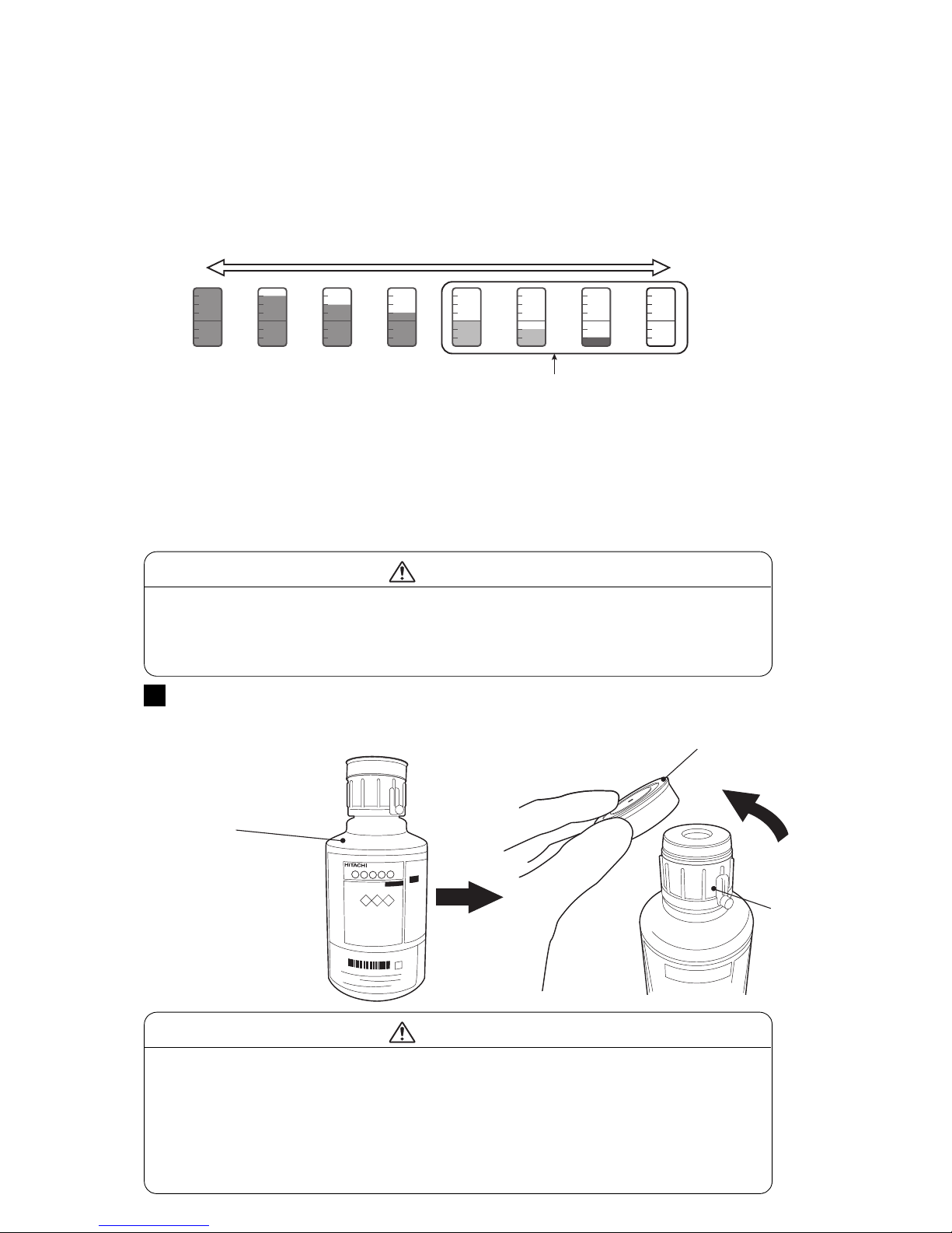
●Replenishing the ink 8-2
8.1 Replenishing the ink
(1) Overview
●Ink can be refilled when the remaining ink icon is at the position which indicates that the cartridge bottle
can be replaced.
●Replenish the ink in the ink reservoir within 60 minutes after an Ink Low warning is generated. If the ink is
not replenished, the printer will stop.
●When the ink is replenished, the warning is automatically reset.
●Ink can only be refilled while the power is ON.
Remove the over cap of an ink cartridge bottle.
The over cap is a cap that is necessary at storage.
It is unnecessary at ink refill.
1
Ink cap
● Do not grip the over cap and lift the cartridge bottle.
The cartridge bottle could be dropped.
● Since an IC chip is built into the cartridge bottle, avoid strong shock and
electromagnetic waves and liquid wetting.
CAUTION
Over cap
Ink cartridge bottle
● When the ink cap was loosened, set it after tightening firmly.
Otherwise the ink may spill when setting the cartridge bottle.
● After removing the over cap, do not allow your finger, foreign matter or dirt to
get into the hole of the ink cap. Doing so could cause ink leakage and
equipment failure.
● Do not change the ink cap of the ink cartridge bottle or makeup cap of the
makeup cartridge bottle. Ink or makeup could spill.
CAUTION
[NOTE] If the color of icon is "Green", the ink cartridge bottle can't be replaced.
●If the ink cartridge bottle with reduced content is set in the printer, the level of the Remaining Ink Icon
displayed on the screen may suddenly drop to the Replaceable Ink level. However, this is not a failure and
the printer operation can be continued.
(2) Operation
Full
Empty
<Remaining Ink Icon>
Replaceable Ink level
Page 60
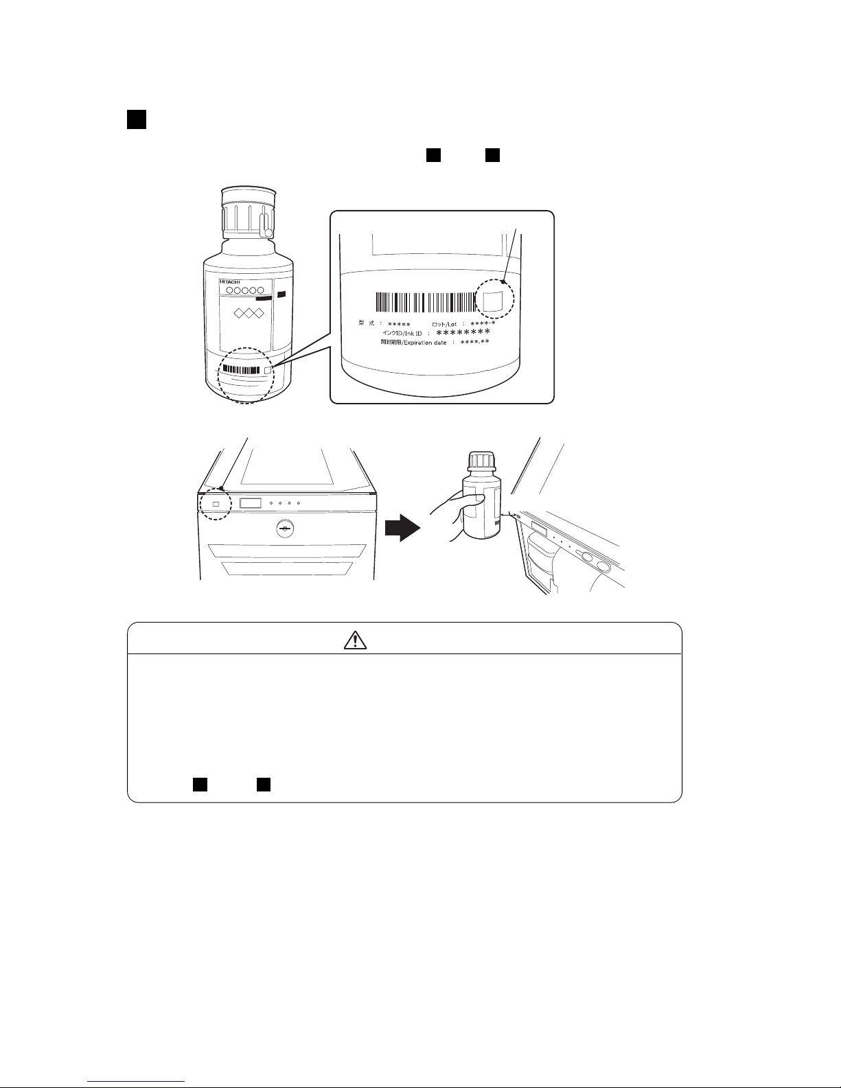
8-3 ●Replenishing the ink
Scan
here
Hold the cartridge bottle over the RFID reader of the printer so that the IC tag
mark of the label on the bottle can be read.
● If the Ink ID is read by the IJ printer, steps -1 and -2 are not necessary.
2
IC tag mark
[When IC tag reader is supported]
RFID Reader
Within 30 mm
2 2
● If there is still ink remaining in the Cartridge bottle, do not replace it even if
the Remaining Ink Icon indicates replacement. This could be due to
malfunction on the parts. Contact your nearest service station.
The part may be broken; contact your nearest service station.
● If there is no reaction when you hold the cartridge bottle over the reader of
the printer, the IC tag of the cartridge may be damaged.
In this case, an ink ID can be input manually from the IJP screen.
(Steps -1 and -2)
CAUTION
2 2
Page 61
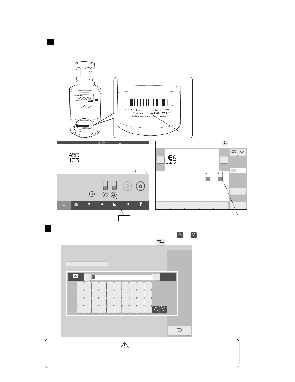
●Replenishing the ink 8-4
[STOP ]
InkIDentry
2015.07.0712:45
Com=0
EntertheInkIDoftheInkcartridgeintotheentry
fieldbelow.
BACK
←
Cancel
Enter→
1 2 3 4 5 6 7 8 9 0
Q W E R T Y U I O P
Z X C V B N
Change
M
A S D F G H J K L
Change
Scan
here
Manually input the ink ID in the ID input area.
To toggle between upper and lower case letters, press the or key.
Printdescription
2015.07.0712:45
SETTINGS
LOGINEDITADJUSTSAVEOPENHOME
Operating Time Ink Presure
(Standard Value:
0.255
)
100h0.000
MPa
Print Count
1.000
Makeup Ink
TEST
START PRINTING
SHUTDOWN
100% +−
OFFLINE
STOP
ID:User2
×
Print description
2015.07.0712:45
Menu
Com=0
[Stop ]
Ink operating time 100(hours)
Cumulative op. time 100(hours)
Print count 1000(prints)
Ink pressure 0.000(MPa;standard value:0.255)
Change
message
Select
message
Overwrite
message
Adjustprint
parameters
Operation
management
Message name[ ]
− +
Current user ID : user2
Interlaced
Printcount
reset
Startup
Manual
Makeup Ink
Change
Change
If manually inputting the ID, touch the icon on the home screen of the IJP,
call up the ID input screen and input the Ink ID.
● An ink ID is printed on the label of the cartridge bottle.
2
[When IC tag reader is not supported]
Icon
Icon
● If the ID cannot be read because it is dirtied by ink, etc., contact your nearest
service station.
CAUTION
-1
Ink ID
2
-2
Page 62
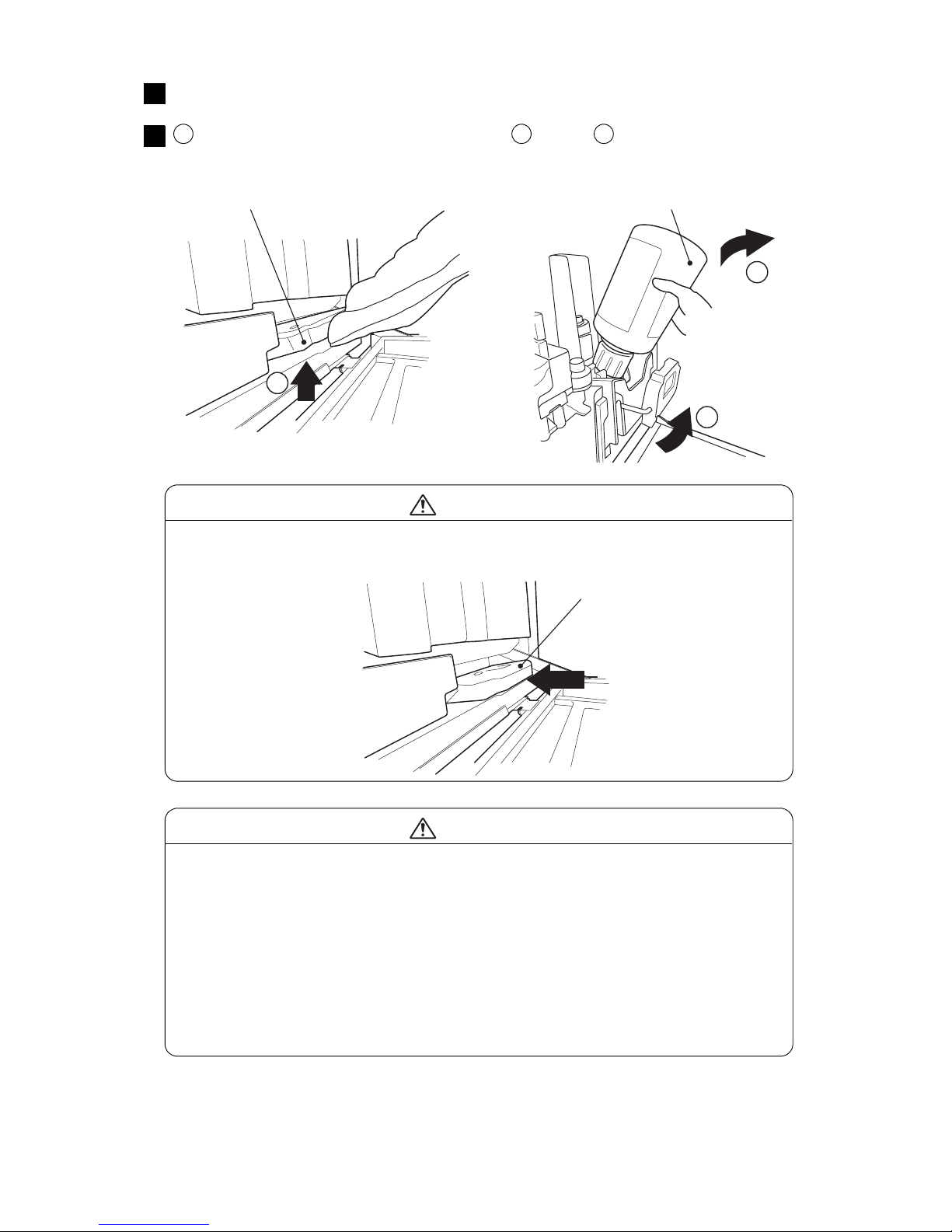
8-5 ●Replenishing the ink
1
2
3
When the ink ID is read, the lock on the ink side is released.
3
Tilt the lever handle toward yourself, lift and remove the
cartridge bottle.
4
Lever handle
Lift the lever handle and remove
the empty cartridge bottle.
● After removing the cartridge bottle from the IJP, quickly place the cap toward
the top. Also do not expose the cartridge bottle to impacts after being removed.
Doing so could cause ink to splatter.
● Do not turn the cartridge bottle with the cartridge bottle set in the IJP.
The ink cap could become loosened and ink may overflow.
● Do not put waste solution in used cartridge bottles.
Waste solution could spill. You should note that used cartridge bottles are not
hermetically sealed even when the over cap is mounted.
● If used cartridge bottles are filled with ink or makeup and reused, ink or
makeup could spill.
CAUTION
1 2 3
● If the lever handle could not be lifted up, do not pull it with excessive force.
In such a case, push the lever handle all the way in.
CAUTION
Lever handle
Push
Page 63
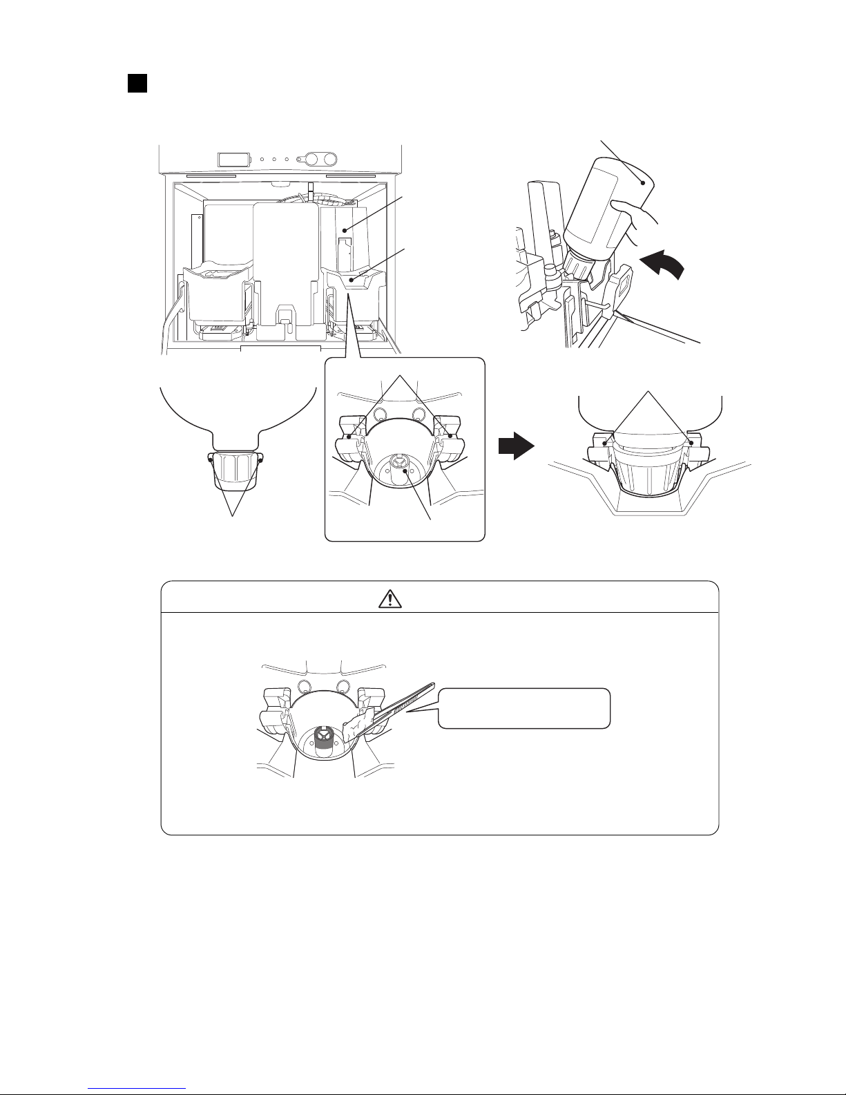
●Replenishing the ink 8-6
Set a new cartridge bottle in the specified position.
Set the boss provided on the cartridge bottle to the boss guide of the ink supply port.
5
Ink side
Pipe
Boss
Set a new cartridge bottle.
Ink supply port
Boss guide
Set the boss to the guide.
● If ink has accumulated on the pipe surface, wipe it up using wiping paper
dampened with makeup.
CAUTION
● If a foreign object such as a screw is found or gets in the ink supply port,
remove it.
Be careful not to damage
the pipe surface.
Page 64
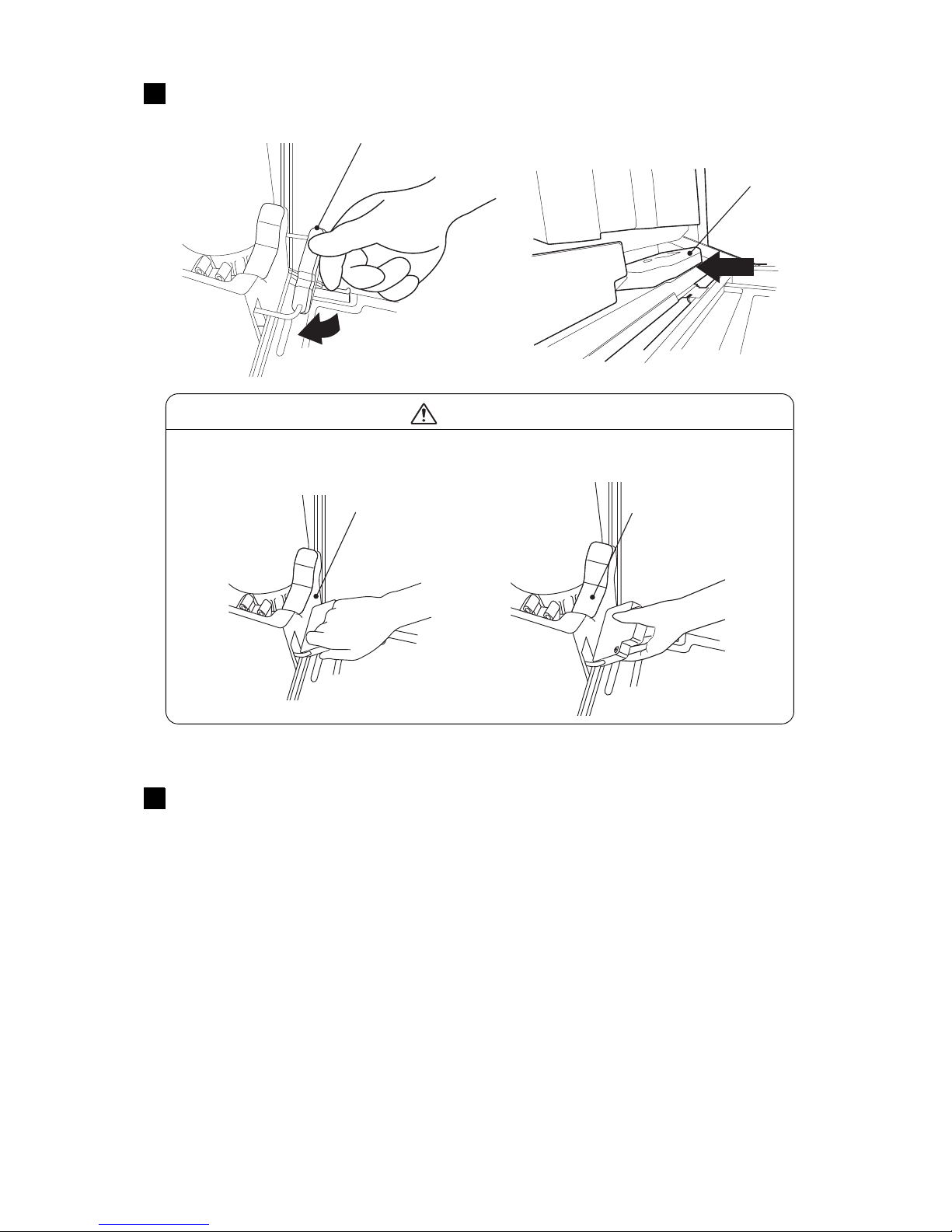
8-7 ●Replenishing the ink
When a new cartridge bottle is set, press the lever handle down and it into the
printer.
6
Lever handle
● Be careful not to get your hand or fingers pinched when pushing down the
lever handle. (See the figure below.)
CAUTION
Lever handle
The cartridge replacement (ink refill) is now completed.
Press <OK> at the IJ printer guidance screen.
Pressing <OK> confirms that ink refill is complete.
7
Lever handle
Lever handle
Push
Page 65
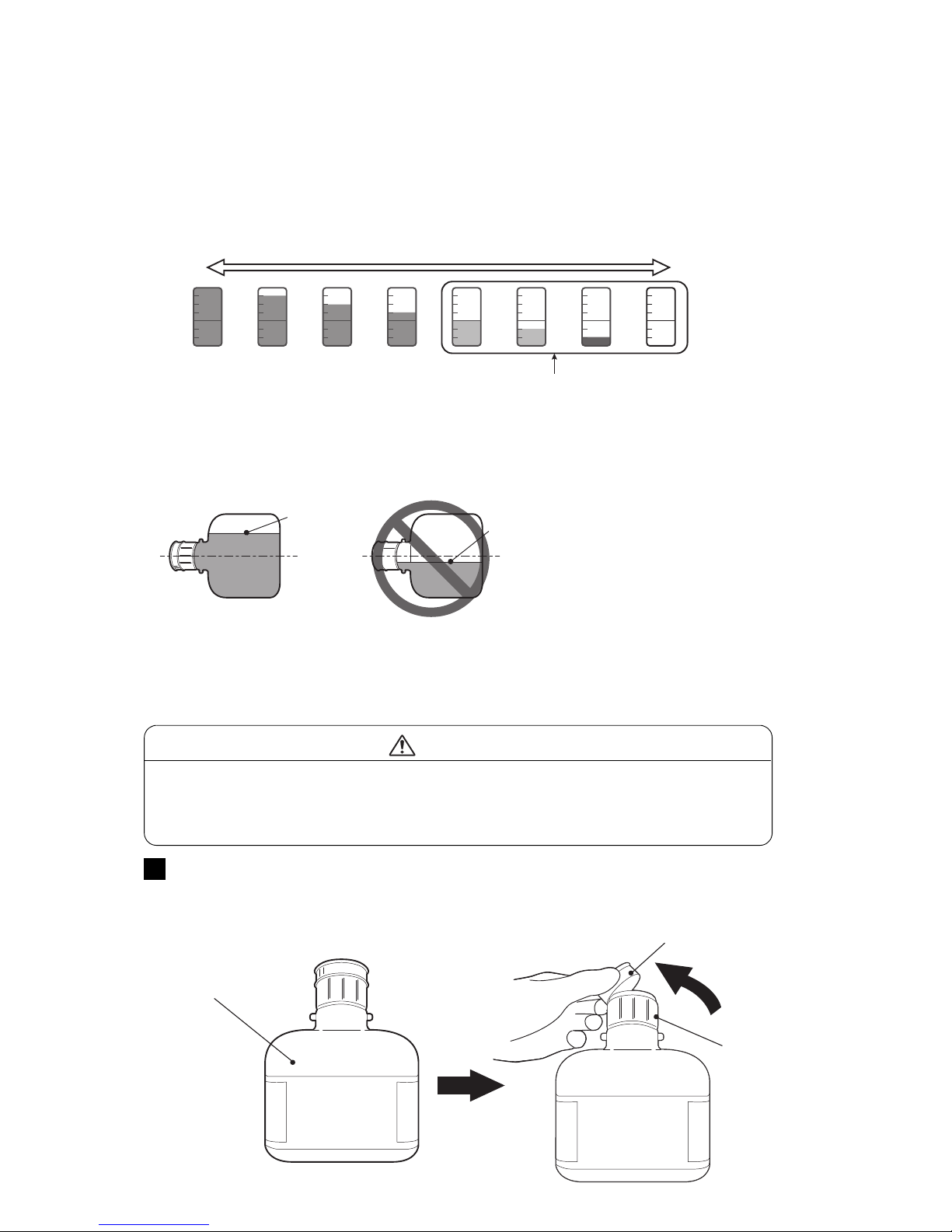
●Replenishing the makeup 8-8
8.2 Replenishing the makeup
(1) Overview
● Makeup can be refilled when the remaining makeup icon is at the position which indicates that the
cartridge bottle can be replaced.
●Replenish the makeup in the makeup reservoir within 60 minutes after a Makeup Low warning is
generated. If replenishment is not performed, the printer will stop.
●When the makeup is replenished, the warning is automatically reset.
●Makeup can only be refilled while the power is ON.
Remove the over cap of a makeup cartridge bottle.
The over cap is a cap that is necessary at storage.
It is unnecessary at ink refill.
1
Makeup cap
Over cap
Makeup
cartridge bottle
● Do not grip the over cap and lift the cartridge bottle.
The cartridge bottle could be dropped.
● Since an IC chip is built into the cartridge bottle, avoid strong shock and
electromagnetic waves and liquid wetting.
CAUTION
[NOTE] If the color of icon is "Green", the makeup cartridge bottle can't be replaced.
●Please set an unopened makeup cartridge bottle or an opened makeup cartridge bottle still has more than
half of its content. Before makeup cartridge bottle with reduced content is set in the printer, place the
cartridge bottle horizontally and confirm its level is more than half of its content.
Full
Empty
<Remaining Makeup Icon>
Replaceable Makeup level
Liquid level
●If the makeup cartridge bottle with reduced content is set in the printer, the level of the Remaining Makeup
Icon displayed on the screen may suddenly drop to the Replaceable Makeup level. However, this is not a
failure and the printer operation can be continued.
(2) Operation
Liquid level
Page 66
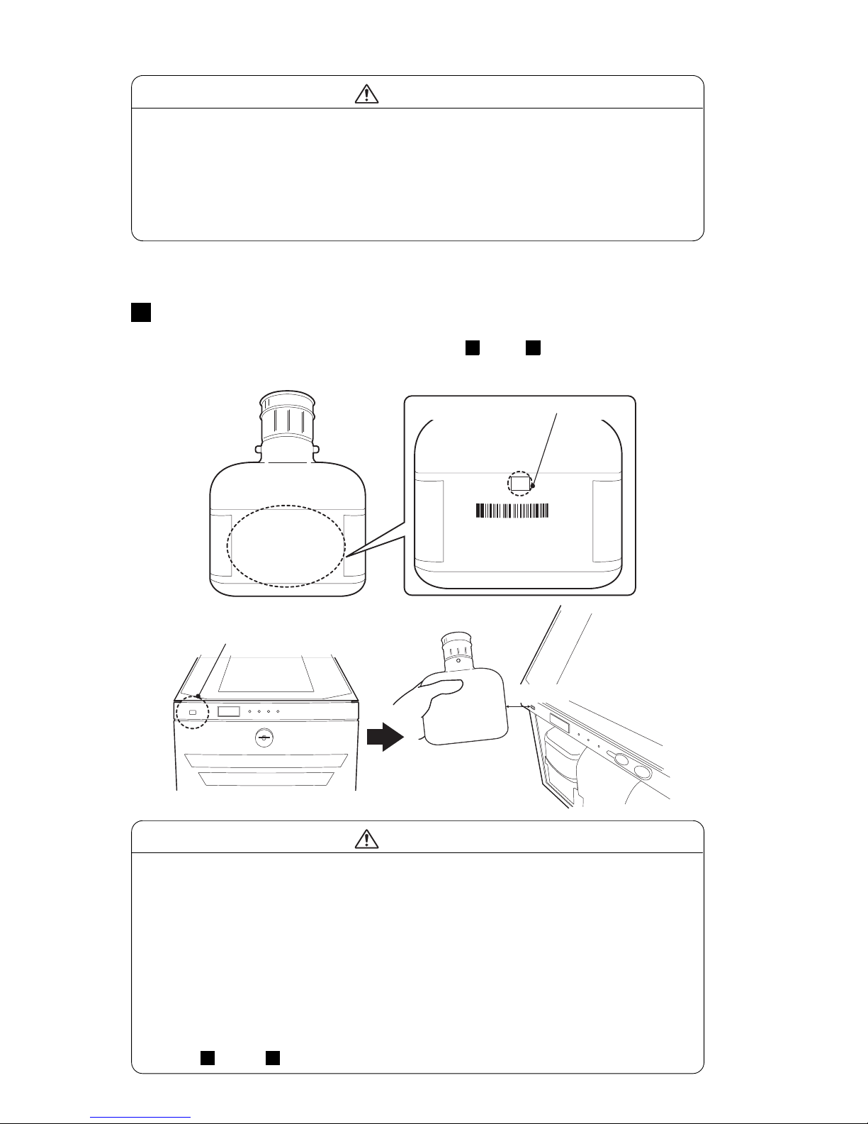
8-9 ●Replenishing the makeup
補力液ID/MakeupID
********
開封期限
/Expirationdate
部品コード
/PartsCode
: ****.**
型 式:*****
ロット/LOT :******
: ******
Scan
here
IC tag mark
[When IC tag reader is supported]
Hold the cartridge bottle over the RFID reader of the printer so that the IC tag
mark of the label on the bottle can be read.
● If the makeup ID is read by the IJ printer, steps -1 and -2 are not necessary.
2
2 2
RFID Reader
Within 30 mm
● When the makeup cap was loosened, set it after tightening firmly.
Otherwise the makeup may spill when setting the cartridge bottle.
● After removing the over cap, do not allow your finger, foreign matter or dirt to
get into the hole of the makeup cap. Doing so could cause makeup leakage
and equipment failure.
● Do not change the ink cap of the ink cartridge bottle or makeup cap of the
makeup cartridge bottle. Ink or makeup could spill.
CAUTION
● If there is still makeup remaining in the Cartridge bottle, do not replace it
even if the Remaining Ink Icon indicates replacement. This could be due to
malfunction on the parts. Contact your nearest service station.
The part may be broken; contact your nearest service station.
● If the makeup cartridge bottle has less than half of its content is set in the
printer, the message "Cartridge replacement error" may be displayed on the
screen. In that case, select the content of makeup cartridge bottle just
replaced according to the guidance displayed on the screern.
● If there is no reaction when you hold the cartridge bottle over the reader of
the printer, the IC tag of the cartridge may be damaged.
In this case, an makeup ID can be input manually from the IJP screen.
(Steps -1 and -2)
CAUTION
2 2
Page 67
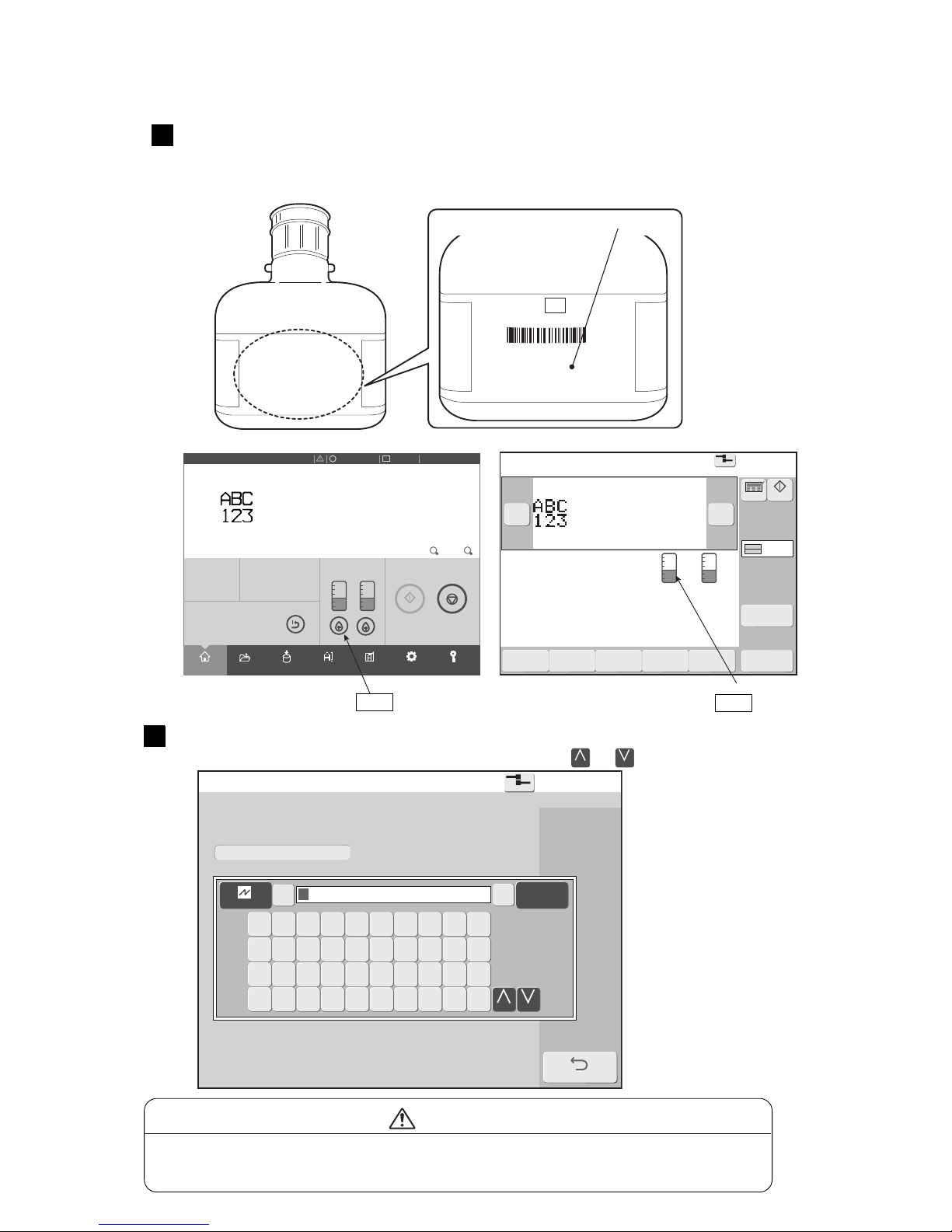
●Replenishing the makeup 8-10
Printdescription
2015.07.0712:45
SETTINGS
LOGINEDITADJUSTSAVEOPENHOME
Operating Time Ink Presure
(Standard Value:
0.255
)
100h0.000
MPa
Print Count
1.000
Makeup Ink
TEST
START PRINTING
SHUTDOWN
100% +−
OFFLINE
STOP
ID:User2
×
Print description
2015.07.0712:45
Menu
Com=0
[Stop ]
Ink operating time 100(hours)
Cumulative op. time 100(hours)
Print count 1000(prints)
Ink pressure 0.000(MPa;standard value:0.255)
Change
message
Select
message
Overwrite
message
Adjustprint
parameters
Operation
management
Message name[ ]
− +
Current user ID : user2
Interlaced
Printcount
reset
Startup
Manual
Makeup Ink
[STOP ]
MakeupIDentry
2015.07.0712:45
Com=0
EntertheMakeupIDoftheMakeupcartridgeinto
theentryfieldbelow.
BACK
←
Cancel
Enter→
1 2 3 4 5 6 7 8 9 0
Q W E R T Y U I O P
Z X C V B N
Change
M
A S D F G H J K L
Change
補力液ID/MakeupID
********
開封期限
/Expirationdate
部品コード
/PartsCode
: ****.**
型 式:*****
ロット/LOT :******
: ******
Scan
here
[When IC tag reader is not supported]
Icon
Icon
● If the ID cannot be read because it is dirtied by ink, etc., contact your nearest
service station.
CAUTION
If manually inputting the ID, touch the icon on the home screen of the IJP,
call up the ID input screen and input the Makeup ID.
● A makeup ID is printed on the label of the cartridge bottle.
2
-1
Makeup ID
Manually input the makeup ID in the ID input area.
To toggle between upper and lower case letters, press the or key.
Change
Change
2
-2
Page 68
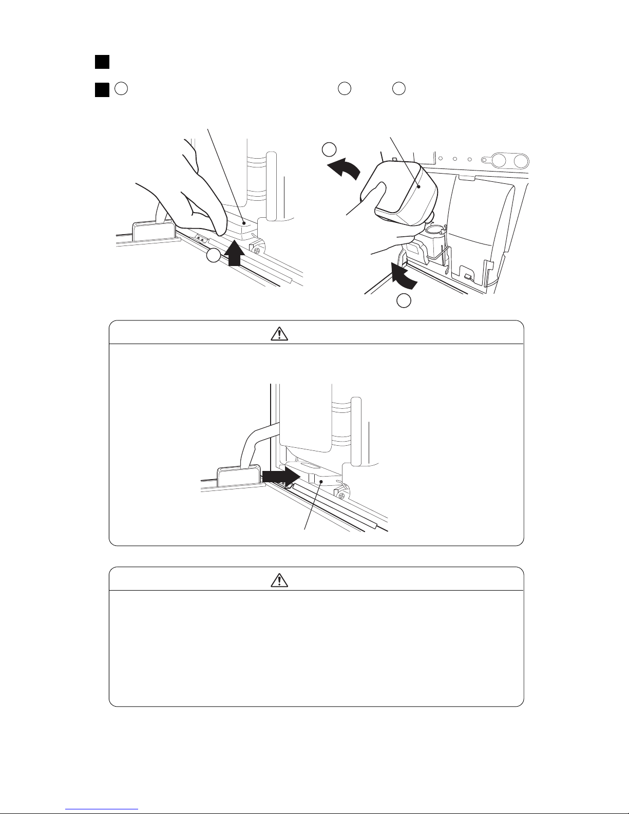
8-11 ●Replenishing the makeup
1
3
2
When the makeup ID is read, the lock on the makeup side is released.
3
Lever handle
Lift the lever handle and remove the empty
cartridge bottle.
● After removing the cartridge bottle from the IJP, quickly place the cap toward
the top. Also do not expose the cartridge bottle to impacts after being removed.
Doing so could cause ink to splatter.
● Do not put waste solution in used cartridge bottles.
Waste solution could spill. You should note that used cartridge bottles are not
hermetically sealed even when the over cap is mounted.
● If used cartridge bottles are filled with ink or makeup and reused, ink or
makeup could spill.
CAUTION
Tilt the lever handle toward yourself, lift and remove the
cartridge bottle.
4
1 2 3
● If the lever handle could not be lifted up, do not pull it with excessive force.
In such a case, push the lever handle all the way in.
CAUTION
Push
Lever handle
Page 69
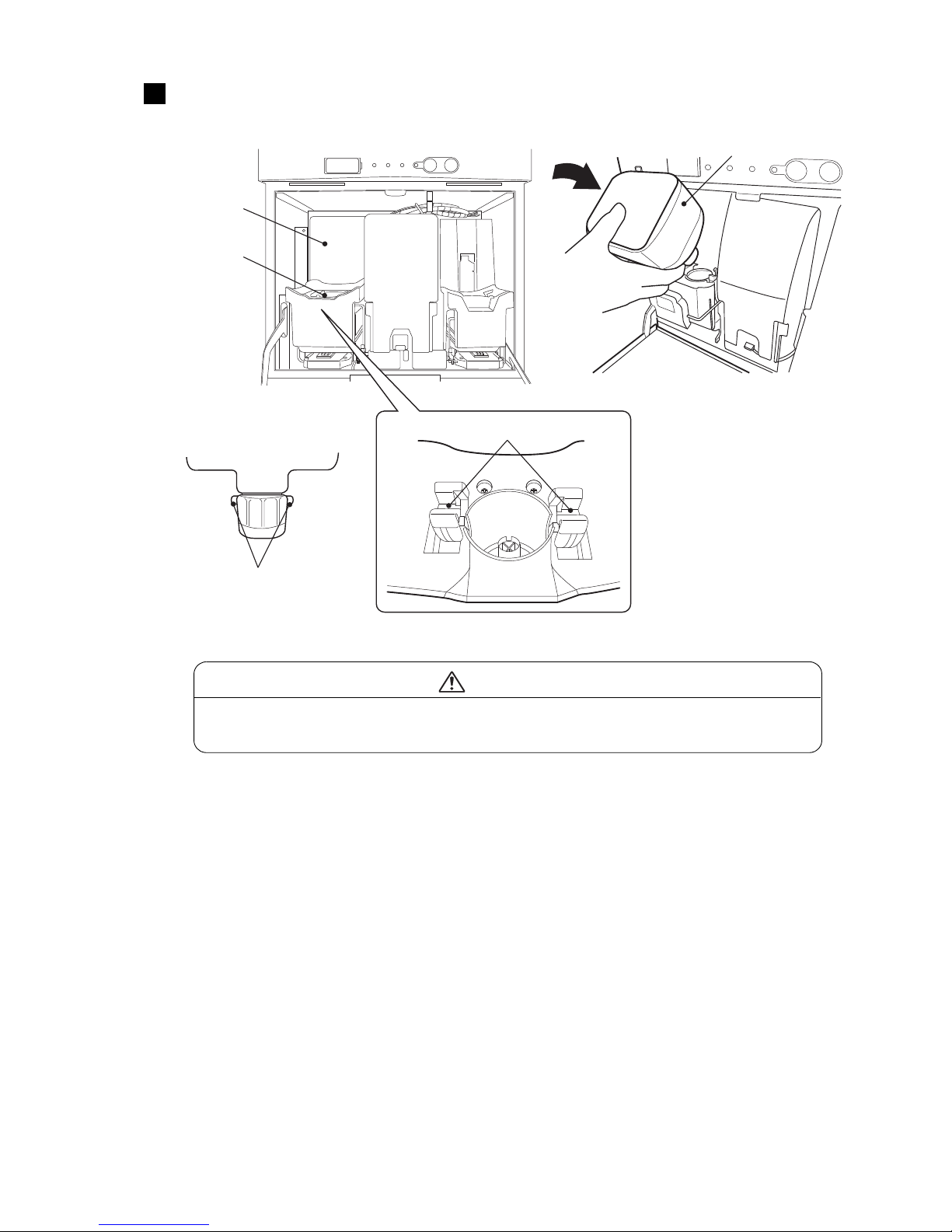
●Replenishing the makeup 8-12
Set a new cartridge bottle in the specified position.
Set the boss provided on the cartridge bottle to the boss guide of the makeup supply port.
5
Makeup side
Boss
● If a foreign object such as a screw is found or gets in the makeup supply port,
remove it.
CAUTION
Set a new cartridge bottle.
Makeup supply port
Boss guide
Page 70
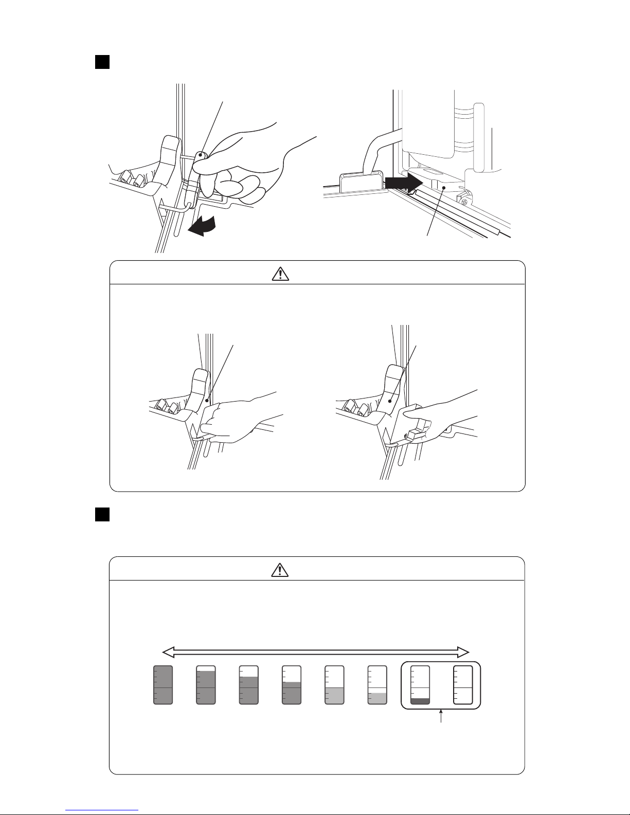
8-13 ●Replenishing the makeup
When a new cartridge bottle is set, press the lever handle down and it into the
printer.
6
Lever handle
● Be careful not to get your hand or fingers pinched when pushing down the
lever handle. (See the figure below.)
CAUTION
Lever handle
The cartridge replacement (makeup refill) is now completed.
Press <OK> at the IJ printer guidance screen.
Pressing <OK> confirms that makeup refill is complete.
7
Lever handle
Lever handle
● The IJ printer on which the “Makeup Level Sensor Broken 1” Fault appeared,
the Makeup Cartridge can NOT be replaced until “Makeup Low” Warning
appears.
CAUTION
Full
Empty
<Remaining Makeup Icon>
Replaceable Makeup level :
After the “Makeup Level
Sensor Broken 1” Fault
appeared.
Page 71
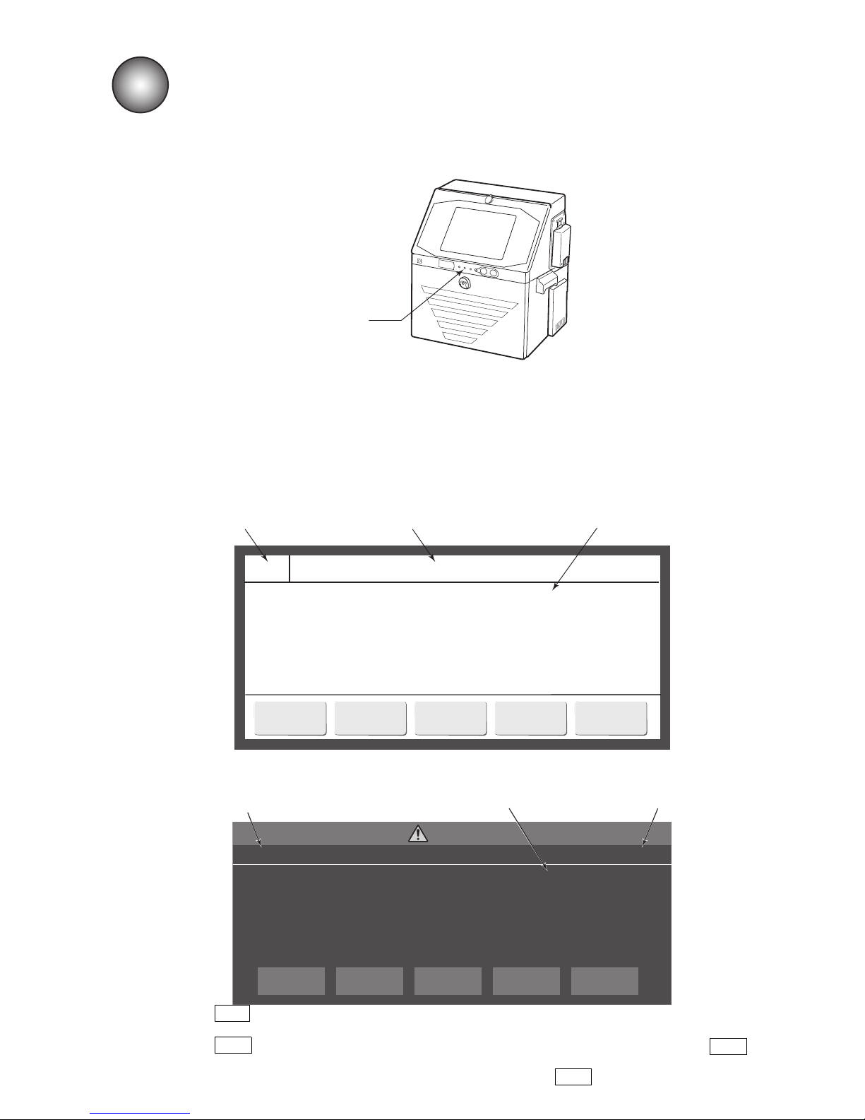
●Display when warning or fault was generated 9-1
◆◆◆◆◆ Target Sensor Fault ◆◆◆◆◆052
The print target detection signal was ON longer than
the timeout setting of Target Sensor Timer.
Cause 1. The print target detection signal ON time is too long.
2. The Target Sensor Timer setting is incorrect.
Solution 1. If the target is stopped in front of the sensor, move the target.
2. Change the Target Sensor Timer setting.
Close
Reset
9. WHEN WARNING OR FAULT
WAS GENERATED
●When an operation mistake is made and processing judgment is prompted, a confirmation message is
displayed.
●When a “Fault state” which hinders printing was generated while the liquid crystal screen
backlighting was off or when a “Warning state” which does not hinder printing but requires
maintenance was generated, a fault message or warning message is displayed in a window.
(1) When a fault was generated
(a) Previous HMI
9.1 Display when warning or fault was generated
●When a warning or fault was generated, a warning or fault lamp lights.
Operational status display lamp
Message No.
The name of the fault
message is displayed.
The description, cause,
and solution are displayed.
Target Sensor Timer out
The print target detector signal was ON longer than
the timeout setting of Target Sensor Timer.
Cause 1. The print target detector signal ON time is long.
2. The Target Sensor Timer setting is incorrect.
Solution 1. If the target is stopped in front of the sensor, move the target.
2. Change the Target Sensor Timer setting.
No.052
FAULT
×
CLOSE
Reset
●When Clear is pressed after removing the cause, the fault state is cleared and the message is also
closed.
●When Close is pressed, the fault window is closed, but the fault state is not cleared. When Fault in
state area, the fault message is displayed again.
●However, when the fault state is already cleared, it is cleared by Close .
(b) New HMI
Message No.
The description, cause,
and solution are displayed.
The name of the fault
message is displayed.
Page 72
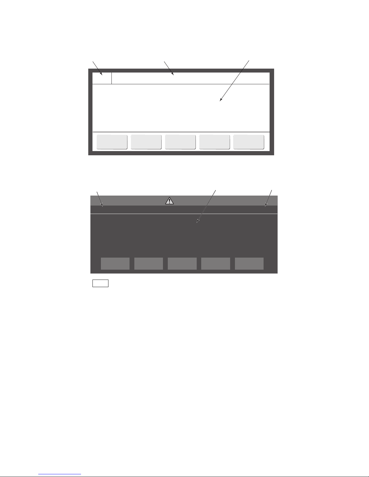
9-2 ●Display when warning or fault was generated
◇◇◇◇◇ Ink Low Warning ◇◇◇◇◇081
The ink level in the ink reservoir is low.
Cause 1. The ink reservoir is almost empty.
2. The Low Level sensor in the ink reservoir is faulty.
Solution 1. Replace the Ink Cartridge within 60 minutes.
2. Check the Low Level sensor.
Close
Ink Low Warning
The ink level in the ink reservoir is low.
Cause 1. The ink reservoir is almost empty.
2. The Low Level sensor in the ink reservoir is faulty.
Solution 1. Replace the Ink Cartridge within 60 minutes.
2. Check the Low Level sensor.
No.081
WARNING
×
CLOSE
●When Close is pressed, the warning window is closed, but the warning state is not cleared.
The warning name is displayed in the warning display area (see the figure above).
●If the warning state is cleared, the warning display is automatically closed.
(2) When warning was generated
(a) Previous HMI
Message No.
The name of the warning
message is displayed.
The description, cause,
and solution are displayed.
(b) New HMI
Message No.
The name of the warning
message is displayed.
The description, cause,
and solution are displayed.
Page 73
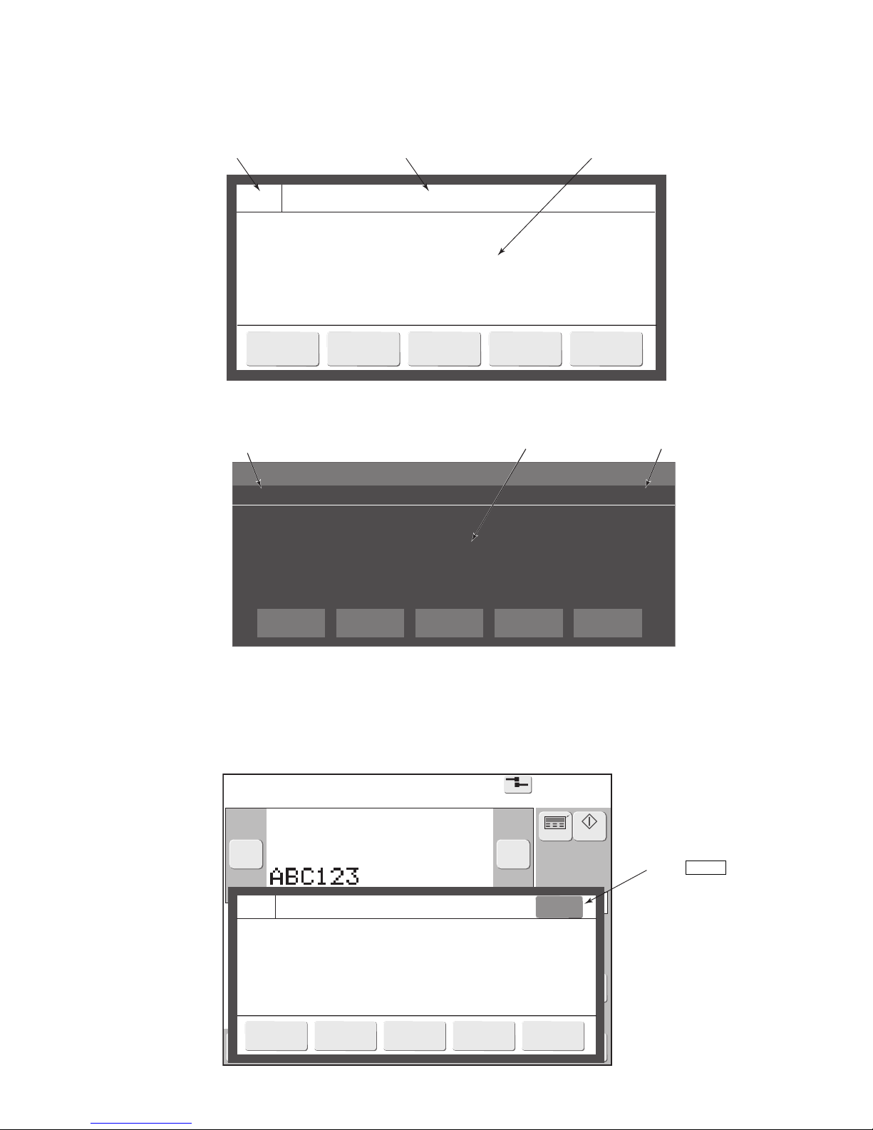
●Display when warning or fault was generated 9-3
===== Ink Jet Startup Confirmation =====186
The ink jet will be turned ON.
Solution To turn the ink jet ON, press <Ready>.
Close
Ready
Print description
2015.07.0712:45
Menu
Com=0
[Stop ]
Ink operating time 100(hours)
Cumulative op. time 100(hours)
Print count 1000(prints)
Ink pressure 0.000(MPa;standard value:0.250)
Change
message
Select
message
Overwrite
message
Adjustprint
parameters
Operation
management
Message name[ ]
− +
Current user ID : user2
Inter-
laced
Printcount
reset
Startup
Manual
Makeup
Ink
◆◆◆◆◆ Main Ink Tank Too Full002
The ink level in the main ink tank is too high.
Cause 1. The valve (MV2) or valve (MV7) is faulty.
2. The High Level sensor in the main ink tank is faulty.
Solution 1. Drain proper amount of ink in the main ink tank.
2. Check the High Level sensor.
3. Contact your local distributor.
Reset
Close
HELP
Ink Jet Startup Confirmation
The ink jet will be turned ON.
Solution 1. To change the printer status to Ready, press <Ready>.
2. To change the printer status to Standby, press <Eject ink>.
No.050
CONFIRMATION
×
Ready CancelEject ink
(3) When a mistake was generated or when processing judgment is prompted
(a) Previous HM
I
●The contents of the confirmation message are described at the place of each operation.
Message No.
The name of the confirmation
message is displayed.
The description, cause,
and solution are displayed.
(4) Guidance for Fault / Waring
(a)Previous HMI
Press HELP , then the
guidance will appear.
Message No.
The name of the confirmation
message is displayed.
The description, cause,
and solution are displayed.
(b) New HMI
Page 74
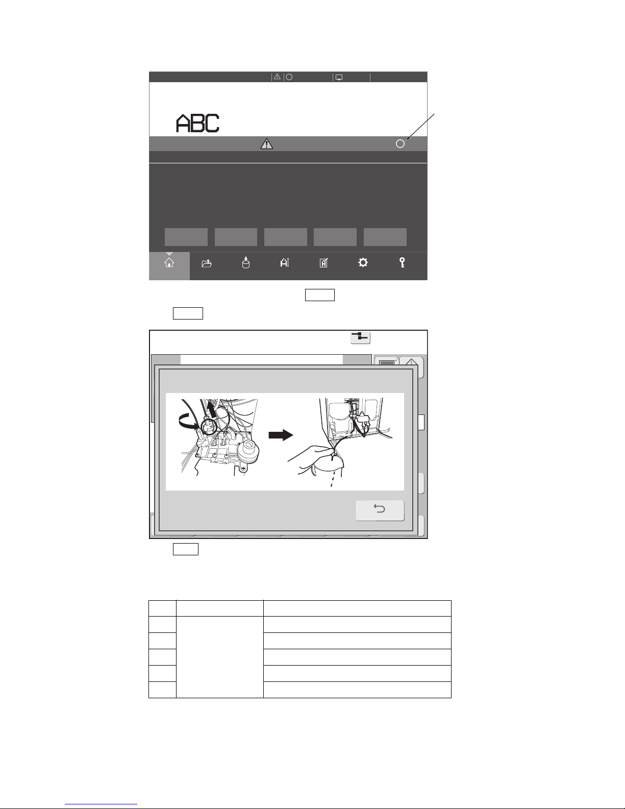
9-4 ●Display when warning or fault was generated
Printdescription
2015.07.0712:45
SETTINGS
LOGINEDITADJUSTSAVEOPENHOME
Operating Time Ink Presure
(Standard Value:
0.255
)
100
h
0.000
MPa
Print Count
1.000
Makeup Ink
TEST
START PRINTING
STARTUP
100% +−
OFFLINE
STOP
ID:User2
×
Main Ink Tank Too Full
The ink level in the main ink tank is too high.
Cause 1. The valve (MV2) or valve (MV7) is faulty.
2. The High Level sensor in the main ink tank is faulty.
Solution 1. Drain proper amount of ink in the main ink tank.
2. Check the High Level sensor.
3. Contact your local distributor.
No.002
Fault
×
Close
Reset
?
Print description
2015.07.0712:45
Menu
Com=0
[Stop ]
Ink operating time 100(hours)
Cumulative op. time 100(hours)
Print count 1000(prints)
Ink pressure 0.000(MPa;standard value:0.250)
Change
message
Select
message
Overwrite
message
Adjustprint
parameters
Operation
management
Message name[ ]
− +
Current user ID : user2
Inter-
laced
Printcount
reset
Startup
Manual
Makeup Ink
1. Drain proper amount of ink in the main ink tank.
Back
● If the message prompts the guidance, HELP will be shown on upper right corner.
● When HELP is pressed, the guidance for the fault/warning will appear.
● When Back is pressed, the guidance will be closed and the message will be shown again.
● The messages listed below have guidance.
No. Type Message
1
Fault
Mai n I n k Tank Too Full
2 Ink Drop Charge Too Low
3 Deflection Voltage Leakage
4 No Ink Drop Charge
5 Ink Drop Charge Too High
(b)New HMI
Displays the guidance.
Page 75
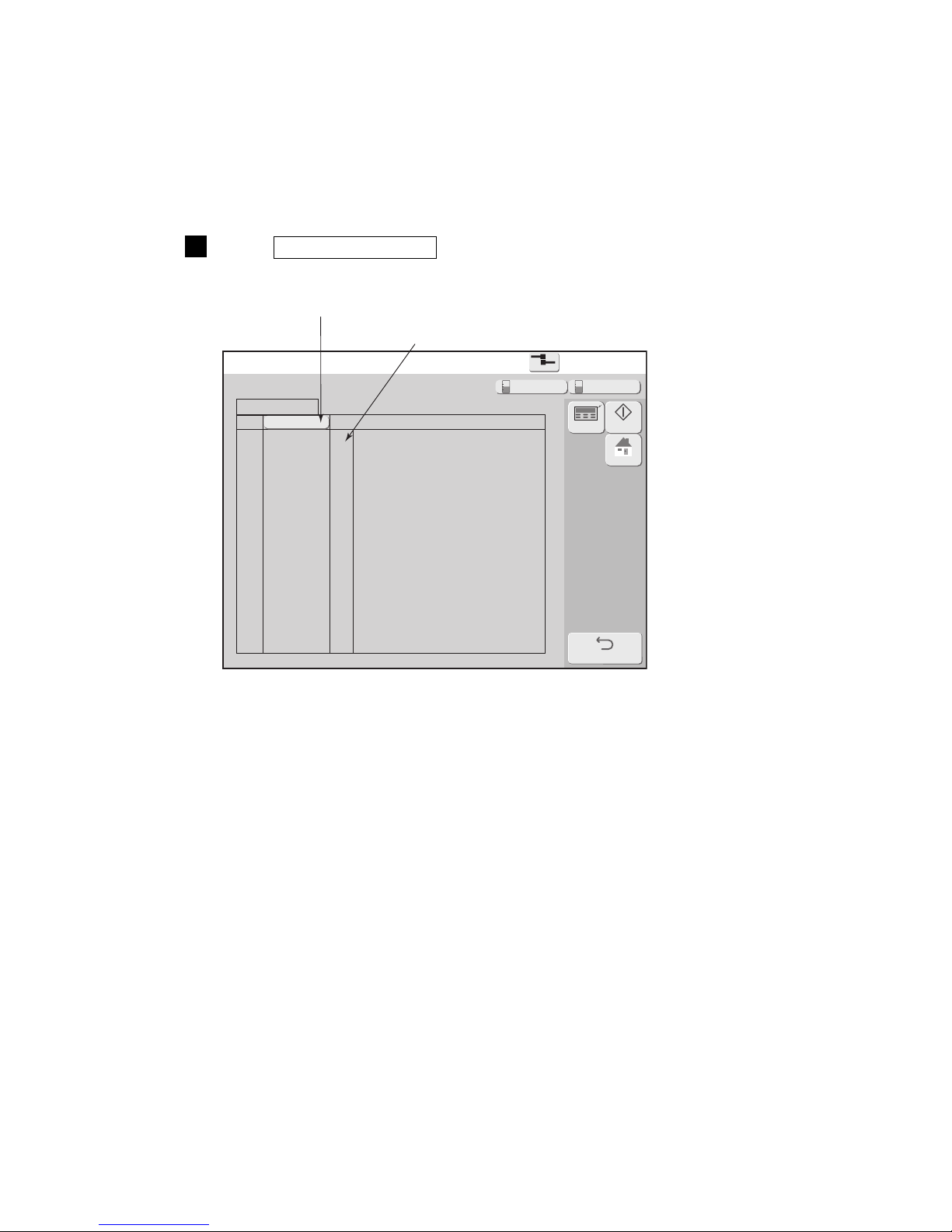
●When checking the warning and fault generation status 9-5
2
Fault/warning log
Fault/warning log
2015.07.0712:45
Com=0
[Stop
]
No
01
02
03
04
05
06
07
08
09
10
11
12
13
14
15
Name of alarm
Date/time
Back
HOME
Startup
Manual
Makeup Ink
9.2 When checking the warning and fault generation status
(1) Functions
●The warning or fault message generation time and contents can be viewed.
●A maximum of 90 messages can be displayed.
●When 90 messages are exceeded, the messages are closed from the oldest message.
(2) Operation
1
Press View alarm history in the Manage messages screen.
The Fault/warning screen is displayed.
Sorted from generation date.
Message No.
Page 76
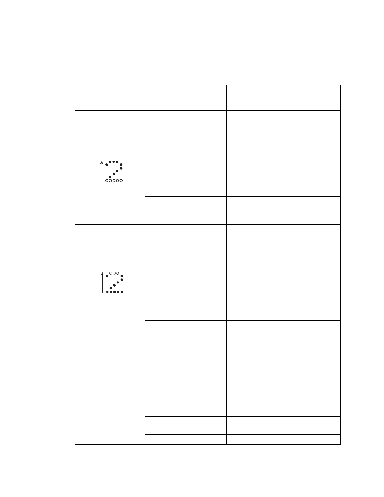
9-6 ●Remedial action to be taken in the event of a printing failure
No.
Printing failure
description
(phenomenon)
Probable cause Solution Reference
1
Chipped print
(minus deflection
electrode side)
Ink and foreign matter are
stuck to the gutter.
● Clean the gutter.
● Replace the recovery
filter.
6.6 (*2)
6.8 (*2)
Ink and foreign matter are
stuck to the charge and
deflection electrodes.
● Clean the charge and
deflection electrodes.
7.1.2
Ink and foreign matter are
stuck to the ink ejection port.
● Remove the ink and foreign
matter.
-
The ink stream is improperly
positioned.
● Adjust the ink stream. 6.5 (*2)
The ink pressure is too high.
● Adjust the ink pressure for
the standard value.
6.9 (*2)
The ink has deteriorated. ● Replace the ink. 6.3 (*2)
2
Chipped print
(plus deflection
electrode side)
Ink and foreign matter are
stuck to the charge and
deflection electrodes.
● Clean the charge and
deflection electrodes.
7.1.2
Ink and foreign matter are
stuck to the ink ejection port.
● Remove the ink and foreign
matter.
-
The flow within the nozzle is
restricted.
● Backwash the nozzle. 6.4 (*2)
The character height setting is
too great.
● Decrease the character
height setting.
4.14.1
(*1)
The ink pressure is too low.
● Adjust the ink pressure for
the standard value.
6.9 (*2)
The ink has deteriorated. ● Replace the ink. 6.3 (*2)
3
Varying character
height
The clearance between the
print head and print target has
changed.
● Adjust the clearance
between the print head and
print target.
-
Ink and foreign matter
are stuck to the charge and
deflection electrodes.
● Clean the charge and
deflection electrodes.
7.1.2
Ink and foreign matter are
stuck to the ink ejection port.
● Remove the ink and
foreign matter.
-
The flow within the nozzle is
restricted.
● Backwash the nozzle. 6.4 (*2)
The ink pressure has changed.
● Adjust the ink pressure for
the standard value.
6.9 (*2)
The ink has deteriorated. ● Replace the ink. 6.3 (*2)
1
9.3 Remedial Action to Be Taken in the Event of a Printing
Failure
● If a printing failure occurs, perform the associated remedial procedures suggested below.
● If the remedial procedures below do not achieve recovery, it is conceivable that the problem is
attributable to a PC board or circulation system failure. In such an instance, contact your nearest local
distributor.
Direction of deflection
←Chipped
(lost)
Direction of deflection
←Chipped
(lost)
(*1) See the Instruction Manual
(*2) See the Technical Manual
Page 77
●Remedial action to be taken in the event of a printing failure 9-7
No.
Printing failure
description
(phenomenon)
Probable cause Solution Reference
4
Disordered
characters
There are water, oil, or other
deposits on the print target
surface.
● Make prints with the print
target clear of deposits.
-
The ink pressure has changed.
● Adjust the ink pressure for
the standard value.
6.9 (*2)
Ink and foreign matter are
stuck to the charge and
deflection electrodes.
● Clean the charge and
deflection electrodes.
7.1.2
The flow within the nozzle is
restricted.
● Backwash the nozzle. 6.4 (*2)
The ink has deteriorated. ● Replace the ink. 6.3 (*2)
The excitation V-ref. value is
improper.
● Adjust the excitation V-ref.. 6.10 (*2)
Page 78
10-1 ●Troubleshooting guide
Phenomenon Check Solution
The power does not turn
ON at the press of the On
switch.
● Check that the main power switch is
turned ON.
● Turn ON the main power switch.
● Check that the power plug is properly
connected to a power outlet.
● Check that electrical power is supplied
to the employed power outlet.
● Turn OFF the main power switch.
Ensure that power is supplied to the
power outlet, and then
connect the power plug to the power
outlet.
● Check that Status indicator lamp is not
on when On switch is pressed.
● Check that On switch is pressed for
about 2 seconds.
● Ensure that Status indicator lamp is off
when pressing the On switch.
● Turn off the main power switch, wait
10 seconds, and the turn back on.
Press the On switch.
● Ensure that Start switch is pressed for
about 2 seconds.
Pressing a key does not
invoke its predefined
operation.
Or the key is not accepted.
● See the Instruction Manual “7.4 Touch Screen Coordinate correction”.
The calendar time is not
correctly printed.
● Check that "clock stop" is not selected
from the date/time setup screen.
See the Instruction Manual “6.2 Set
the Date and Time”.
● Select the "same as current time"
option.
See the Instruction Manual “6.2 Set
the Date and Time”.
The printer does not
become ready for
printing when Start up is
pressed.
● Check for an ink stream ejection from
the nozzle.
● Check whether the ejected ink stream
enters the gutter hole.
● Stop the ink ejection sequence by
pressing the Shut down .
● See the Technical Manual “6.4 How to
correct ink stream bending and nozzle
clogging”, and correct the problem.
● Check if the print head are dirty.
● See “2.3 Print head cleaning”, and
perform the operation.
“Print overlap fault”
occurs frequently.
See “9. When Warning or Fault was generated”.
A fault message is
displayed.
Residual image of
characters, etc. remains on
the screen.
-
●Because of the characteristics of the
liquid crystal panel, when the same pattern is displayed for a long time, a
residual image of the pattern may
remain. However, the residual image
will disappear with the passage of time.
RFID cannot be read. -
●The tag may be broken. Manually input
the ID referring to "8. Refilling ink and
makeup".
The cartridge cannot be
changed without releasing
the lock.
- ●Push the lever into the equipment.
10. TROUBLESHOOTING GUIDE
If the printer does not start up normally, perform the following checks before deciding the printer is malfunctioning.
● If the above remedies do not restore the printer to normal, stop using
the printer, disconnect the power plug from the power outlet, and
contact your Hitachi distributor.
CAUTION
■ Report the following to your local source or service company:
1. TYPE-FORM (model number) IJ printer (Model UX- )
2. SER. No. (serial number) UX
3. Failure description In detail
4. Organization name (department and section names included), name of person in charge, and
telephone number.
* The model number and serial number are marked on the nameplate that is attached to the right-hand side of the printer.
Page 79
●Maintenance service 11-1
About maintenance service
If trouble or damage occurs within 1 year after delivery or accumulated operating time of 2400 hours, whichever
is sooner, repairs will be made free of charge. However, the following cases are outside the warranty even within
the free warranty period:
(1) When trouble was due to handling outside the instruction manual
(2) When materials and parts other than ours, including the ink, were used and damage was caused by them
(3) When repair was performed by other than us or our designated representative and damage was caused by
this
(4) When trouble was due to external causes (abnormal print material, etc.) other than this equipment or by
moving or transportation of the equipment after delivery
(5) When operated in a usage environment outside the specifications of par. “13. Specifications” of the
instruction manual.
(6) When damaged by fire, water, or other natural disaster
Loss of production due to down time and physical loss due to trouble or error of delivered equipment
(loss of print material, related facility, etc.) is outside the warranty. If trouble occurs, an engineer shall
be dispatched as quickly as possible and maximum efforts will be made so that the down time is as
short as possible.
If there is no danger of being misread, excessive or insufficient dot configuration shall be considered
allowable.
The IJ printer has an alarm function to prevent major printing faults before they happen, but this function does not inspect the quality of the printed characters.
Consideration shall be given so that the printed character state is visible at some process.
Parts retention period
The retention period of the performance parts for repair of this equipment is 7 years after discontinuation of
manufacture.
“Performance parts for repair” are parts necessary to maintain the functions of the product.
Customer memo:
Please fill in for later use.
Useful when communicating with the service in charge.
Your Hitachi sales representative:
Your Hitachi distributor:
Date of purchase: year month day
Tel:
Person in charge:
Tel:
Person in charge:
11. MAINTENANCE SERVICE
Page 80
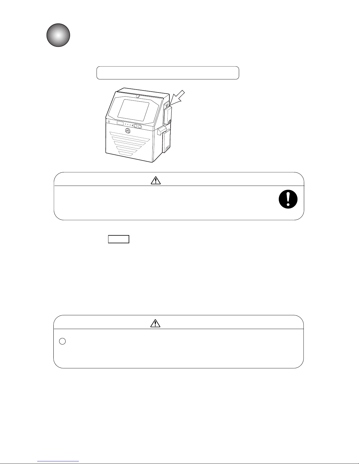
12-1 ●Emergency Procedures
12. EMERGENCY PROCEDURES
Press the main power switch to turn OFF the power.
● If an earthquake, fire, or other emergency arises while the printer is
operating or when its power is on, turn OFF the power by pressing the
main power switch.
Never perform this procedure except in case of an emergency.
WARNING
● Immediately after the emergency is cleared, press the main power switch to turn the power back
ON and press the Start up to initiate ink ejection.
● If the emergency lasts for 5 minutes or longer, open the print head cover and clean the orifice plate
and its surrounding parts and gutter section by pouring makeup over them.
When resuming operation, thoroughly clean the orifice plate and its surrounding parts and gutter
section by pouring makeup over them, and then initiating ink ejection.
● If the power supply is shut off by a power failure, perform the same procedure as indicated above.
In the event of a power failure
When you use the printer after power restoration, be sure to confirm the printings
and other setup data beforehand. If you find any incorrect printings or setup
data, correct it.
CAUTION
1
Main power switch
Page 81
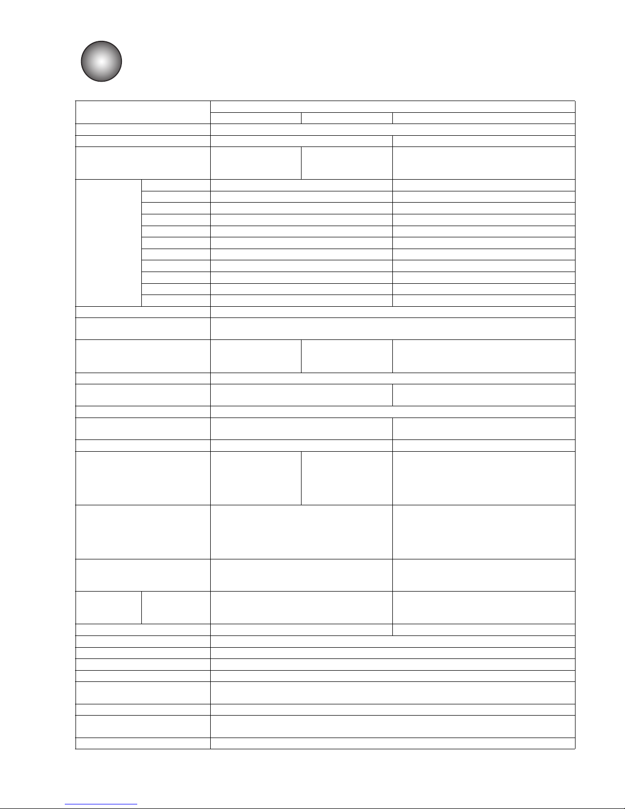
●Specifications 13-1
13. SPECIFICATIONS
Item
Model
UX-E160 W/S UX-D160 W/S UX-B160 W/S
Nozzle size 65μm
Max. print line number Up to 6 lines Up to 3 lines
Maximum number of print
characters
Up to 1,000 characters
Up to 240 characters
(OP: Up to 1000
characters)
Up to 240 characters
Font
4x5 V 5x5 V V
5x7(8),9x7(8) V V
7x10 V V
11x11 V (Chinese only) V (Chinese only)
10x12 V V
12x16 V V
18x24 V V
24x32 V 30x40 V 36x48 V -
Character height 2-10 mm / 0.08-0.39 inches
Display & input device
WYSIWYG design; Display: TFT LCD (10.4" color), backlight provided;
Input device: Touch panel, input sound provided
Maximum print rate
(character per second)
(Font 5x5, space 1, 1line)
Up to 2,296
Up to 1,148
(OP: Up to 2,296)
Up to 1,148
Standard characters Alphanumeric (A-Z, a-z, 0-9), symbols (27), space : Total 90
User pattern
Each dot matrix 200 patterns
(30 × 40, 36 × 48: 50 characters)
Each dot matrix 50 patterns
Print functions Calendar, Count, Font mixture, Passwords security, etc.
Barcode printing
code39, ITF, NW-7, EAN-13, EAN-8, UPC-A,
UPC-E, code128/EAN-128, GS1 DataBar
-
2D code printing Data Matrix , QR code, Micro QR -
Message storage capacity
2,000 messages
(depends on data
content)
300 messages
(Op: Up to 2000
messages
(depends on data
content))
150 messages
Input signal
Print target detection, Rotary encoder pulse,
OP:Printing stop, Reciprocative printing,
Remote control (Run, Stop, High-voltage ON/
OFF, Reset)
(NPN/PNP Selectable)
Print target detection, Rotary encoder pulse
(NPN/PNP Selectable),
OP:Printing stop,
Reciprocative printing,
Remote control (NPN/PNP Selectable)
Output signal
Print ready, Fault, Warning (NPN Only),
OP:Print in progress or Print complete,
Online (NPN/PNP Selectable)
Print ready, Fault, Warning (NPN Only),
OP:Print in progress or Print complete,
Online (NPN/PNP Selectable)
Data interface RS-232C
RS-232C at baud rates selectable up to
115,200bps
Option
(RS-232C at baud rates selectable up to
115,200bps)
Ethernet IEEE802.3, 100BASE-T External memory USB for user data storage
Head cable length, angle 4m / 13.1ft, inline / 90 degrees
Operating temperature range 0-50ºC / 32-122ºF (Refer to “Handling guidance of each ink” manual)
Humidity range 30-90% R.H. (No condensation)
Power supply
(Automatic voltage selection)
AC100-120/220-240V±10% 50/60Hz 120VA (AC Inlet)
Corrosive gas There must be no corrosive gas
Overall size
(Width x Depth x Height)
400x320x527mm / 15.7x12.6x20.8 inches
Approximate weight 27kg / 60lbs
Page 82
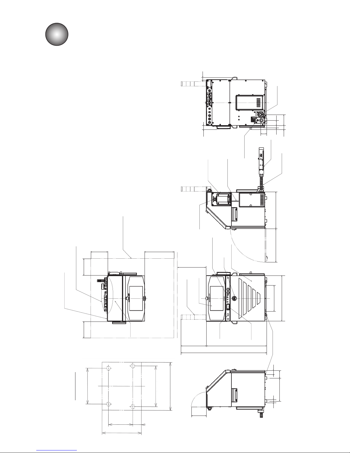
14-1 ●Outside Dimensions
Fig.14-1 Model UX IJ printer outside dimensions
30
201 68
34
128
(With topcover open)
230
400
USB
cover
RFID
reader
527
747
220
State indicator
light
Touch screen
250
(Maintenance
area)
Operating status
indicator lamps
Knob
Maintenance
cover
295
(With maintenance
cover open)
Cabinet
mounting
screws
(M4-2places)
320
Print head
cable (4m)
Print head
Power cable
(AC100V only)
Power inlet
(φ7
〜
10)
Power switch
53
45
9634
18
Exhaust
dact (φ50)
31
24
300 300
300
750
Maintenance area
External interface inlets
State indicator light
attacting portion
Top
cover
Purging air
inlet (Rc1/8)
300
340
(Front)
(400)
(320)
68 201
Location of feet
14. SCHEMATIC DIAGRAMS
14.1 Outside Dimensions
Page 83
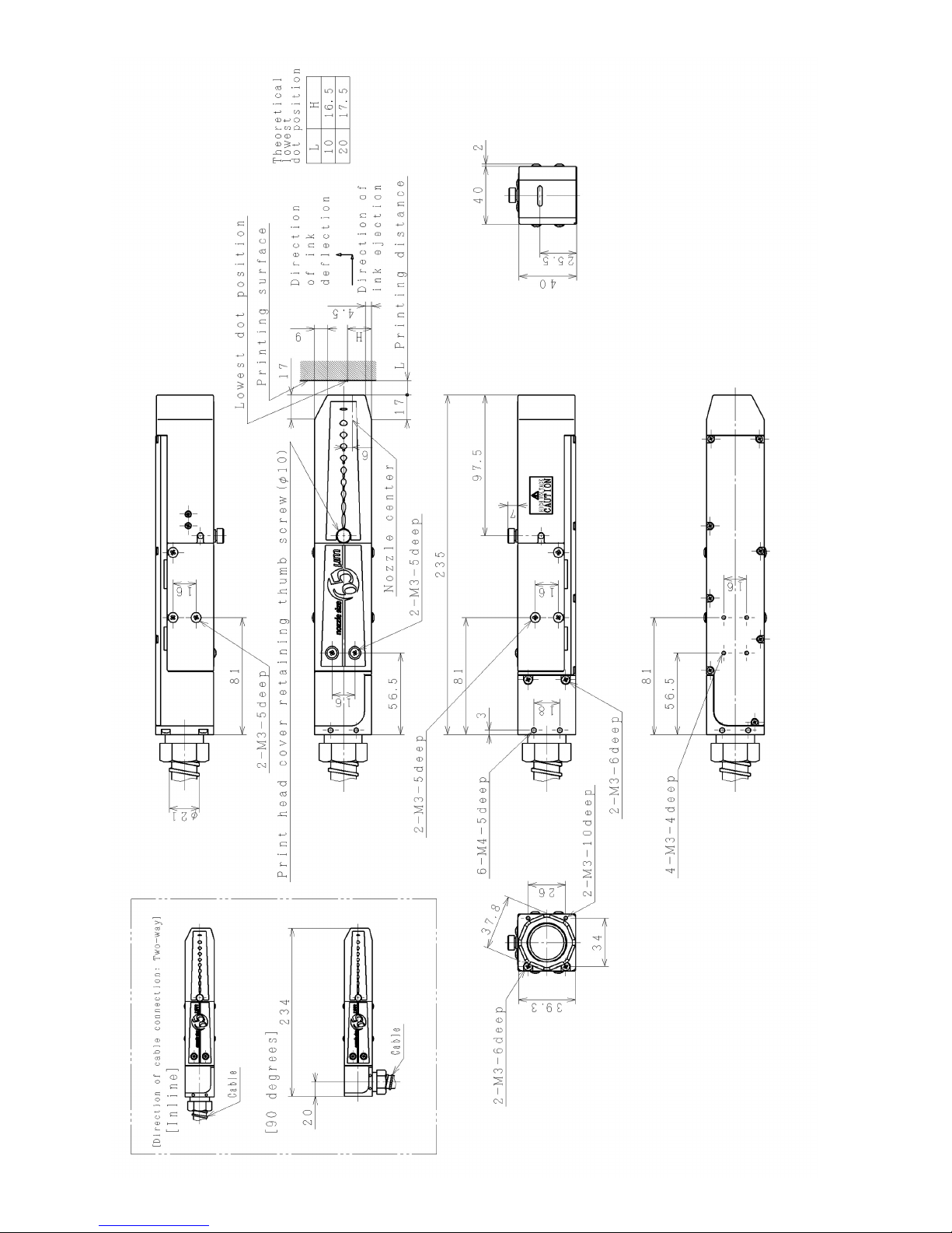
●Outside Dimensions 14-2
Fig.14-2 Model UX-D,B Print head outside dimensions
Page 84
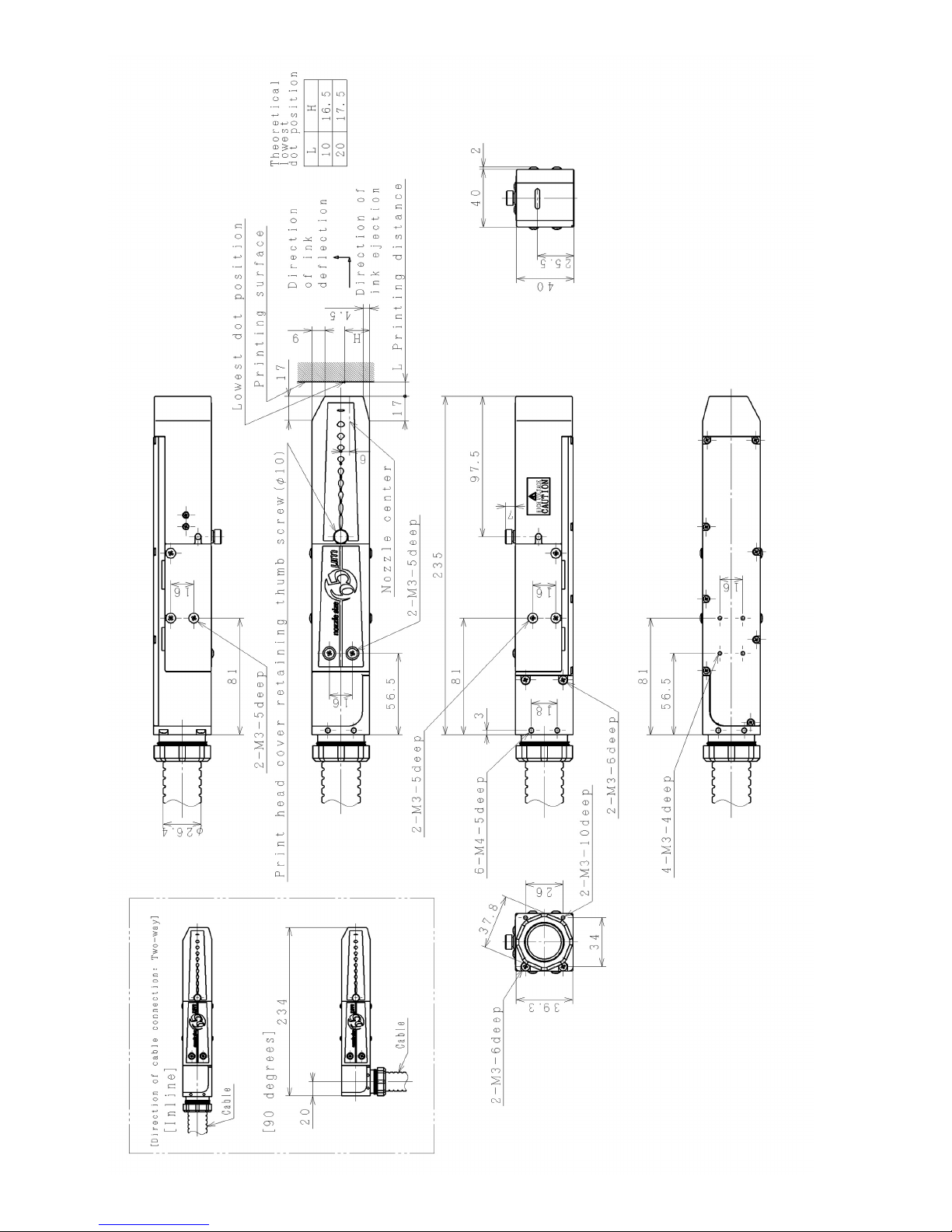
14-3 ●Outside Dimensions
Fig.14-3 Model UX-E Print head outside dimensions
Page 85

●Appendix 15-1
A
Adjust print parameters . . . . . . . . . . . . . . . . . . . . . . . . . . . . . . . . . . . . . . . . . . . . . . . . . . . . . . . . . . . . .7-19
Air purge . . . . . . . . . . . . . . . . . . . . . . . . . . . . . . . . . . . . . . . . . . . . . . . . . . . . . . . . . . . . . . . . . . . . . . . . .5-1
B
Beaker with handle . . . . . . . . . . . . . . . . . . . . . . . . . . . . . . . . . . . . . . . . . . . . . . . . . . . . . . . . . . . . . . . . .1-1
C
Cable clip. . . . . . . . . . . . . . . . . . . . . . . . . . . . . . . . . . . . . . . . . . . . . . . . . . . . . . . . . . . . . . . . . . . . . . . . .1-2
Cable seal . . . . . . . . . . . . . . . . . . . . . . . . . . . . . . . . . . . . . . . . . . . . . . . . . . . . . . . . . . . . . . . . . . . . . . . .1-2
Calendar time . . . . . . . . . . . . . . . . . . . . . . . . . . . . . . . . . . . . . . . . . . . . . . . . . . . . . . . . . . . . . . . . . . . 10-1
Change message. . . . . . . . . . . . . . . . . . . . . . . . . . . . . . . . . . . . . . . . . . . . . . . . . . . . . . . . . . . . . 7-19, 7-20
Cleaning bottle. . . . . . . . . . . . . . . . . . . . . . . . . . . . . . . . . . . . . . . . . . . . . . . . . . . . . . . . . . . . . .1-1, 2-1, 7-6
Create/Edit message . . . . . . . . . . . . . . . . . . . . . . . . . . . . . . . . . . . . . . . . . . . . . . . . . . . . . . . . . . . . . . .7-19
E
Edit message. . . . . . . . . . . . . . . . . . . . . . . . . . . . . . . . . . . . . . . . . . . . . . . . . . . . . . . . . . . . . . . . 7-19, 7-20
H
Handling the nozzle rubber seal . . . . . . . . . . . . . . . . . . . . . . . . . . . . . . . . . . . . . . . . . . . . . . . . . . . . . .7-17
I
Ink and makeup replenishment . . . . . . . . . . . . . . . . . . . . . . . . . . . . . . . . . . . . . . . . . . . . . . . . . . . . 2-1, 8-1
Ink heating . . . . . . . . . . . . . . . . . . . . . . . . . . . . . . . . . . . . . . . . . . . . . . . . . . . . . . . . . . . . . . . . . . . . . . . .2-5
Ink periodic replacement . . . . . . . . . . . . . . . . . . . . . . . . . . . . . . . . . . . . . . . . . . . . . . . . . . . . . . . . . . . . .2-1
Ink replacement . . . . . . . . . . . . . . . . . . . . . . . . . . . . . . . . . . . . . . . . . . . . . . . . . . . . . . . . . . . . . . . . . . . .1-1
Ink Temperature Correction Notice . . . . . . . . . . . . . . . . . . . . . . . . . . . . . . . . . . . . . . . . . . . . . . . . . . . . .2-5
Inter-character space. . . . . . . . . . . . . . . . . . . . . . . . . . . . . . . . . . . . . . . . . . . . . . . . . . . . . . . . . . . . . . .7-20
L
Login user . . . . . . . . . . . . . . . . . . . . . . . . . . . . . . . . . . . . . . . . . . . . . . . . . . . . . 7-2, 7-12, 7-19, 7-22, 7-24
M
Magnifying glass . . . . . . . . . . . . . . . . . . . . . . . . . . . . . . . . . . . . . . . . . . . . . . . . . . . . . . . . . . . . . . . . . . .1-1
Main power switch . . . . . . . . . . . . . . . . . . . . . . . . . . . . . . . . . . . . . . . . 3-1, 7-1, 7-2, 7-13, 7-16, 10-1, 12-1
N
No Ink Concentration Control . . . . . . . . . . . . . . . . . . . . . . . . . . . . . . . . . . . . . . . . . . . . . . . . . . . . . . . . .2-6
No-cleaning stop . . . . . . . . . . . . . . . . . . . . . . . . . . . . . . . . . . . . . . . . . . . . . . . . . . . . . . . . . . . .2-4, 7-4, 7-5
15. APPENDIX
INDEX
Page 86

15-2 ●Appendix
O
On switch. . . . . . . . . . . . . . . . . . . . . . . . . . . . . . . . . . . . . . . . . . . . . . . . . . . . . . . . . . . . 7-1, 7-2, 7-13, 10-1
P
Password protection . . . . . . . . . . . . . . . . . . . . . . . . . . . . . . . . . . . . . . . . . . . . . . . . . . . . . . . . . . 7-12, 7-21
Plastic bag with zipper. . . . . . . . . . . . . . . . . . . . . . . . . . . . . . . . . . . . . . . . . . . . . . . . . . . . . . . . . . . . . . . 1-2
Print format . . . . . . . . . . . . . . . . . . . . . . . . . . . . . . . . . . . . . . . . . . . . . . . . . . . . . . . . . . . . . . . . . 7-19, 7-20
Print head . . . 1-1, 1-2, 2-3, 2-5, 3-1, 3-4,4-1, 4-2, 4-3, 5-1, 6-1, 7-3, 7-8, 8-1, 9-6, 10-1, 14-1, 14-2, 14-3
Print head cable. . . . . . . . . . . . . . . . . . . . . . . . . . . . . . . . . . . . . . . . . . . . . . . . . . . . . . . . 4-1, 4-2, 4-3, 14-1
Print specification . . . . . . . . . . . . . . . . . . . . . . . . . . . . . . . . . . . . . . . . . . . . . . . . . . . . . . . . . . . . 7-19, 7-20
R
Ready state . . . . . . . . . . . . . . . . . . . . . . . . . . . . . . . . . . . . . . . . . . . . . . . . . . . . . . . . . . 7-4, 7-9, 7-10, 7-11
Ready state → Standby state switching . . . . . . . . . . . . . . . . . . . . . . . . . . . . . . . . . . . . . . . . . . . . . . . . 7-10
S
Select login user . . . . . . . . . . . . . . . . . . . . . . . . . . . . . . . . . . . . . . . . . . . . . . . . 7-2, 7-12, 7-19, 7-22, 7-24
Select message . . . . . . . . . . . . . . . . . . . . . . . . . . . . . . . . . . . . . . . . . . . . . . . . . . . . . . . . . . . . . . . . . . .7-19
Shift code. . . . . . . . . . . . . . . . . . . . . . . . . . . . . . . . . . . . . . . . . . . . . . . . . . . . . . . . . . . . . . . . . . . . . . . . 7-20
Standby state. . . . . . . . . . . . . . . . . . . . . . . . . . . . . . . . . . . . . . . . . . . . . . . . . . . . . . . . . . . . .7-9, 7-10, 7-11
Standby state → Ready state switching . . . . . . . . . . . . . . . . . . . . . . . . . . . . . . . . . . . . . . . . . . . . . . . . 7-11
Stop state. . . . . . . . . . . . . . . . . . . . . . . . . . . . . . . . . . . . . . . . . . . . . . . . . . . . . . . . . . . . . . . . . . . . . . . . . 2-6
Stop switch . . . . . . . . . . . . . . . . . . . . . . . . . . . . . . . . . . . . . . . . . . . . . . . . . . . . . . . . . . 3-1, 7-1, 7-13, 7-16
Substitution rule. . . . . . . . . . . . . . . . . . . . . . . . . . . . . . . . . . . . . . . . . . . . . . . . . . . . . . . . . . . . . . . . . . . 7-21
T
Time count. . . . . . . . . . . . . . . . . . . . . . . . . . . . . . . . . . . . . . . . . . . . . . . . . . . . . . . . . . . . . . . . . . . . . . . 7-20
Tweezers . . . . . . . . . . . . . . . . . . . . . . . . . . . . . . . . . . . . . . . . . . . . . . . . . . . . . . . . . . . . . . . . . . . . . . . . .1-1
Page 87

Page 88

2S23L6267-8B
 Loading...