

Hitachi UT32MH70E, UT32MH70U, UT37MX70E, UT37MX70U, UT42MX70E Service manual
...
SM0430
UT32MH70E
UT32MH70U
UT37MX70E
SERVICE MANUAL
MANUEL D'ENTRETIEN
WARTUNGSHANDBUCH
CAUTION:
Before servicing this chassis, it is important that the service technician read the “Safety
Precautions” and “Product Safety Notices” in this service manual.
ATTENTION:
Avant d’effectuer l’entretien du châassis, le technicien doit lire les «Précautions de sécurité»
et les «Notices de sécurité du produit» présentés dans le présent manuel.
VORSICHT:
Vor Öffnen des Gehäuses hat der Service-Ingenieur die „Sicherheitshinweise“ und „Hinweise
zur Produktsicherheit“ in diesem Wartungshandbuch zu lesen.
UT37MX70U
UT42MX70E
UT42MX70U
Data contained within this Service
manual is subject to alteration for
improvement.
Les données fournies dans le présent
manuel d’entretien peuvent faire l’objet
de modifications en vue de perfectionner
le produit.
Die in diesem Wartungshandbuch
enthaltenen Spezifikationen können sich
zwecks Verbesserungen ändern.
Contents
1. Features -----------------------------------------------3
2. Specifi cations ----------------------------------------- 3
3. Servicing ----------------------------------------------- 5
4. Controls ------------------------------------------------ 6
5. Adjustment -------------------------------------------- 8
6. Troubleshooting ------------------------------------ 18
7. Wiring diagrams ----------------------------------- 23
8. Block diagrams ------------------------------------- 37
9. Connector diagram ------------------------------- 43
10.Schematic diagrams ------------------------------ 44
11.PCB Layout diagrams -------------------------- 105
12.Disassembly diagrams ------------------------ 111
13.Replacement Parts list ------------------------- 121
SPECIFICATIONS AND PARTS ARE SUBJECT TO CHANGE FOR IMPROVEMENT
LCD Monitor
April 2008
UT32-MH70U/E / UT37-MX70U/E / UT42-MX70U/E (D8MW)
CAUTION FOR SAFETY
Please read this page before repairing the monitor.
This page explains the following items for keeping the safety of the set and preventing accidents
during repair.
Symbols Used:
Warning
Caution
This symbol means "CAUTION"
This symbol means "POSSIBLITY of
ELECTRIC SHOCK"
This symbol means "possiblity of death or heavy damage"
This symbol means "possiblity of damage or breakage"
Follow instructions.
Special attention parts are indicated on the
cabinet, chassis and parts by label.
Please follow the notes in [Safety Instructions]
in the User’s Manual.
Prevent electric shock.
Take care during working because the
monitor has high voltage parts and power
supply parts.
Possibility of death if these parts are
touched by mistake.
Disconnect power plug during overhaul,
reassembly or parts change.
Death or injury by electric shock may
occur if live parts are touched.
Use recommended components.
Components and perts with special
characteristics for safety or reliability are
indicated in partslists and circuits diagrams
by the "!" mark.
Electric shock or fire amy occur if nonrecommended parts/component are used.
This symbol means "MUST"
This symbol means "DO NOT"
WARNING
Keep the same style of wiring..
Monitor uses insulating tubes or tapes
for safety and some components are
kept at a distance from PCB surfaces
for safety.
Internal leads are kept from hot- or high voltage
parts by clampers or styling. Return wiring to
original condition after repair to prevent electric
shock or fire.
Perform safety check after finished.
Every part (removed screws, components
and wiring) should be returned to its
original condition.
Check around the repair position for
damage and measure the insulation
impedance by using a meg-ohm meter.
Confirm that the value of impedance
is more than 4M ohm.
Electric shock or fire may occur if the
value is less than 4M ohm.
1
UT32-MH70U/E / UT37-MX70U/E / UT42-MX70U/E (D8MW)
Cleaning and Maintenance
Please make sure to unplug the power lead before cleaning the unit.
ʄ
Cleaning the LCD panel of the unit.
Wipe the panel with a lint-free and dry cloth in order to prevent damage to the panel surface.
Do not use a chemical cloth or cleaners. Depending on the ingredients, these may cause discolouration and damage to the panel
surface.
Do not wipe with a rough cloth or rub hard. This may damage the panel surface.
With greasy dirt such as fingerprints, wipe the panel surface with a lint-free cloth moistened with a diluted neutral detergent
solution (dilute 1 part of detergent to 100 parts of water) and then wipe with a soft and dry cloth.
Do not use a spray cleaner.This could cause a malfunction.
ʄ
Cleaning the cabinet of the unit.
The following may cause cracking, deformation and peeling of paint.
Do not wipe the cabinet with benzene, thinners and other chemical products.
Do not spray volatile solutions such as insecticide over the cabinet.
Do not leave the cabinet in prolonged contact with plastic or rubber materials.
Do not use a chemical cloth, cleaner or wax. Depending on the ingredients, these may cause cracking and deformation.
Use a lint-free cloth (e.g. cloth for cleaning glasses) to clean the cabinet and control panel of the unit. In case of the excessive dirt,
wipe with a soft cloth moistened with a diluted neutral detergent solution and then wipe with a soft and dry cloth.
Never use the following detergents. They could cause cracking, discolouration and scratching.
Acidic/alkaline detergents, alcoholic detergents, abrasive cleaners, soap powder, OA cleaner, car wax, glass cleaner, etc.
Information for users applicable in European Union countries
This symbol on the product or on its packaging means that your electrical and electronic
equipment should be disposed at the end of life separately from your household waste.
There are separate collection systems for recycling in EU. For more information, please contact the local authority or the dealer where you purchased the product.
2
UT32-MH70U/E / UT37-MX70U/E / UT42-MX70U/E (D8MW)
1. Features
• Ultra-slim-line LCD monitor.
• Large-screen and high-definition LCD.
• Enjoy high resolution display.
(32-inch model: 1366 (H) x 768 (V) pixels, 37-inch model: 1920 (H) x 1080 (V) pixels)
• Improved digital signal processor.
• High quality sound with deeper, richer and dynamic bass tones.
• Accepts a digital input device with HDMI terminal.
• Enjoy the image from your PC with a large, high-definition LCD screen.
• Easy-to-use On-screen Display system operated by remote control.
• Low power consumption with power saving feature.
2. Specifications [For 32- & 37-inch versions ONLY]
SPECIFICATION
Approx. 32 inches
(698 (H) x 392 (V) mm, diagonal 801mm)
Including Stand:
814 (W) x 587 (H) x 249 (D) mm
excluding Stand:
814 (W) x 538 (H) x 39* (D) mm
* thinnest part: 35mm
Including Stand: 13.5 kg
Excluding Stand: 10.9 kg
AC220 - 240V, 50Hz
Panel
Net dimensions
Net weight
Ambient
conditions
Power supply
Display dimensions
Temperature Operating: 5°C to 35°C, Storage: 0°C to 40°C
Relative humidity Operating: 20% to 80%, Storage: 20% to 90% (non-condensing)
Power consumption/ at standby
(HDMI input)
Input terminals
Input signals
(RGB/Composite input)
Input terminals
Input signals
yS ȍ]
HDMI : HDMI input terminal
Audio input terminal (Mini-pin)*
HDMI: VGA/60, 480i, 576i, 480p, 576p, 720p/50, 720p/60, 1080i/50, 1080i/60,
1080p/50, 1080p/60, 1080p/24
Analogue RGB input terminal (D-sub 15 pin)
Audio input terminal (Mini-pin)*
0.7 Vp-p, analogue RGB (Recommended Signal)
Composite video: PAL, SECAM, NTSC3.58, NTSC4.43, PAL60, PAL-M, PAL-N
K2[levelLTT,etarapesV/Hslangiscn
Approx. 37 inches
(820 (H) x 461 (V) mm, diagonal 941mm)
Including Stand:
936 (W) x 657 (H) x 310 (D) mm
excluding Stand:
936 (W) x 607 (H) x 39* (D) mm
* thinnest part: 35mm
Including Stand: 17.4 kg
Excluding Stand: 14.6 kg
W8.0</W171W8.0</W231
W6+W6rekaepSW6+W6rekaepStuptuooiduA
slexip)V(0801x)H(0291slexip)V(867x)H(6631noituloseR
The unit takes at least 30 minutes to attain the status of optimal picture quality.
* This Analogue Audio Input terminal can be used for PC (RGB) or HDMI-DVI.
3
UT32-MH70U/E / UT37-MX70U/E / UT42-MX70U/E (D8MW)
2. Specifications [For 42-inch versions ONLY]
SPECIFICATION
Panel
Net dimension
UT42-MX700A
(HDMI input)
Input terminals
Input signals
(RGB/Composite input)
Input terminals
Input signals
Sync signals H/V separate, TTL level [2K]
The unit takes at least 30 minutes to attain the status of optimal picture quality.
* This analog audio input terminal can be used for PC (RGB) or HDMI-DVI.
Net Weight
Ambient conditions
Power supply AC110-240V, 50/60Hz
Power consumption/ at stand by 244W/<0.8W
Audio output speaker 6W + 6W
Display dimensions Approx. 42 inches (930 (H) x523 (V) mm, diagonal 1067mm)
Resolution 1920 (H) x 1080 (V) pixels
including Stand: 1036 (W) x 728 (H) x 310 (D) mm
excluding Stand: 1036 (W) x 678 (H) x 39*(D) mm
*thinnest part: 35mm
including Stand: 20.9kg
excluding Stand: 18.0kg
Temperature Operating: 5°C to 35°C, Storage: 0°C to 40°C
Relative humidity Operating: 20% to 80%, Storage: 20% to 90% (non-condensing)
HDMI : HDMI input terminal
Audio input terminal (Mini-pin)*
HDMI: VGA/60, 480i, 576i, 480p, 576p, 720p/50, 720p/60, 1080i/50,
1080i/60, 1080p/50, 1080p/60, 1080p/24
Analog RGB input terminal (D-sub 15 pin)
Audio input terminal (Mini-pin)*
0.7 Vp-p, analog RGB (Recommended Signal)
Composite video: PAL, SECAM, NTSC3.58, NTSC4.43, PAL60, PAL-M,
PAL-N
4
UT32-MH70U/E / UT37-MX70U/E / UT42-MX70U/E (D8MW)
3. Servicing
Lead free solder
All PCB assemblies in this unit use lead free solder.
This product uses lead free solder (unleaded) to help preserve the environment. Read these
instructions before attempting any soldering work.
Caution: Always wear safety glasses to prevent fumes or molten solder from getting into the eyes. Lead
free solder can splatter at high temperatures (600˚C).
Lead free solder indicator
Printed circuit boards using lead free solder are engraved with an "F."
Properties of lead free solder
The melting point of lead free solder is 40-50˚C higher than leaded solder.
Servicing solder
Solder with an alloy composition of Sn-3.0Ag-0.5Cu or Sn-0.7Cu is recommended.
Although servicing with leaded solder is possible, there are a few precautions that have to be taken. (Not
taking these precautions may cause the solder to not harden properly and lead to consequent malfunctions.)
Precautions when using leaded solder
Remove all lead free solder from soldered joints when replacing components.
If leaded solder should be added to existing lead free joints, mix in the leaded solder thoroughly after the
lead free solder has been completely melted (do not apply the soldering iron without solder).
Servicing soldering iron
A soldering iron with a temperature setting capability (temperature control function) is recommended.
The melting point of lead free solder is higher than leaded solder. Use a soldering iron that maintains a high
stable temperature (large heat capacity) and that allows temperature adjustment according to the part being
serviced, to avoid poor servicing performance.
Recommended soldering iron:
Soldering iron with temperature control function (temperature range: 320-450˚C)
Recommended temperature range per part:
Part Soldering iron temperature
Mounting (chips) on mounted PCB 320˚C±30˚C
Mounting (chips) on empty PCB 380˚C±30˚C
Chassis, metallic shield, etc. 420˚C±30˚C
5
UT32-MH70U/E / UT37-MX70U/E / UT42-MX70U/E (D8MW)
4. Controls
[Main unit]
Front Panel
6
7
Control panel (on the underside)
Cabinet
1
2
3
4
5
1
2
Panel
3
Remote Control Receiver
Indicating Lamp
4
Speaker
5
Illumination Lamp
6
Tabletop Stand
7
19
(
Power switch
8
Control Terminal*
9
Service use only
10
11
PC (RGB)/DVI Analogue Audio Input Terminal
12
PC Connection Terminal (D-sub 15 Pin)
13
Reset button
18
17
15
16
)(
OK
(Ż)(Ź)
)
14
(ź)(Ÿ)
13
11
10
9
12
Ÿ button
14
ź button
15
16
Volume Up/Ź button
17
Volume Down/Ż button
18
Input Select/OK button
19
Menu/Return button
8
* The Control Terminal allows linked operation with a Hitachi Media Box which equips a control terminal with the
logo.
Rear Panel
Power Cord Socket
1
HDMI Input Terminal
2
2
1
6
[Remote control]
UT32-MH70U/E / UT37-MX70U/E / UT42-MX70U/E (D8MW)
Power On/Off
Press this button to switch
monitor On or Off standby.
Power Off
Press this button to switch
monitor Off standby.
RGB Input Select
Press this button to select
RGB (/Composite) input.
Menu
Cursor
OK
Input Select
Press this button to change
input mode.
HDMI RGB (/Composite)
Auto Adjust
Press this button to adjust the
picture automatically in RGB
mode.
Power On
Press this button to switch
monitor On.
Volume Up/Down
Mute
HDMI Input Select
Press this button to select
HDMI input.
Recall
Press this button to show the
input signal status.
Return
Press this button to return to
the previous menu.
Picture Mode
Picture mode can be changed
each time pressed in the
following sequence.
Dynamic Natural
Cinema
Size
Press this button to change
picture size.
7
UT32-MH70U/E / UT37-MX70U/E / UT42-MX70U/E (D8MW)
5. Adjustment
Setting service adjustment mode
There are two methods as follows:
Method 1) Push the power switch with the “Menu/Return” button on the main unit pushed.
Keep pushing the “Menu/Return” button until the service screen is displayed.
Method 2) Keep pushing “Return” for about 3 seconds while pressing “Menu” and “Recall” of remote controller
at the same time.
The service screen appears.
Ending the service adjustment mode
1) Push the “Power switch” or “Menu” button on the main unit.
2) Push the “Power” or “Menu” button on the remote controller.
Operation (use the remote controller)
“ “ “ “ key ------ Selection of adjustment item (1 line)
“ “ “ “ key ------ Data adjustment
“OK” key ------ Enter
“Mute” key ------- reset the default value
5.1 Colour temperature adjustment
Average data has already been written in the Main Board for service parts.
You may not adjust it if there is no necessity.
5.1.1 Colour temperature adjustment of “Cool” mode
Adjustment Preparations Adjustment Procedures
(1)
Adjustment signal: HDMI 1080i
Signal pattern: White raster
Video level: 90%
(2)
Picture settings: Factory setting, Check that the
mode is set as Factory Adjustment mode.
Picture mode: Dynamic
(3)
The colour analyzer (CA-210) should be proof
read by a spectrum radiation brightness meter
such as CS-1000 or standard LCD.
(4)
Set aspect to Full mode.
(5)
Set the colour analyzer (CA-210) at the centre
of the panel.
Set Factory Adjustment mode.
(1)
Check that the initial data of adjustment No.000,
(2)
No.001 and No.002 of service adjustment menu
is the following value. If the initial data is
different, set it to the following data.
Adjustment No.000=230
No.001=230
No.002=240
Receive a white raster signal. Step down either
(3)
R DRV_COOL (No.000), G DR V_COOL (No.001)
or B DRV_COOL (No.002) of the two (Or, one)
values and adjust to the following value.
(Note)
At least one of the data should be initial data.
Specification
Video colour temperature (Cool)
x㧩0.266 r0.005
y㧩0.270 r0.005
14000K r0MPCD
[Remarks]
(1) Colour temperature should be adjusted under the condition in which the screen is the brightest, thus the initial value
of adjustment is set at maximum. This adjustment only decreases brightness.
(2) Beware there is RESET in each of Picture mode.
(3) When adjustment number 000, 001 or 002 is selected, the colour temperature changes cool mode.
8
UT32-MH70U/E / UT37-MX70U/E / UT42-MX70U/E (D8MW)
5.1.2 Colour temperature adjustment of “Normal” mode
Adjustment Preparations Adjustment Procedures
(1) Same as “Cool mode” adjustment.
(1) Set Factory Adjustment mode.
(2)
(3)
Check that the initial data of adjustment No.003,
No.004 and No.005 of the service adjustment
menu is the following value. If the initial data is
different, set it to the following data.
Adjustment No.003=224
No.004=224
No.005=224
Receive a white raster signal. Step down either
R DRV_NORMAL (No.003), G DR V_NORMAL
(No.004) or B DRV_NORMAL (No.005) of the two
(Or, one) values and adjust to the following value.
(Note)
[Remarks]
(1) Colour temperature should be adjusted under the condition in which the screen is the brightest, thus the initial value
of adjustment is set at maximum. This adjustment only decreases brightness.
(2) Beware there is RESET in each of Picture mode.
(3) When adjustment number 003, 004 or 005 is selected, the colour temperature changes normal mode.
At least one of the data should be initial data.
Specification
Video colour temperature (Normal)
x㧩0.285r0.005
y㧩0.293r0.005
9300Kr0MPCD
9
UT32-MH70U/E / UT37-MX70U/E / UT42-MX70U/E (D8MW)
5.1.3 Colour temperature adjustment of “Warm” mode
Adjustment Preparations Adjustment Procedures
(1) Ssame as “Cool mode” adjustment.
Adjustment of colour temperature “Cool mode”
should be completed first.
(1)
(2)
(3)
Set Factory Adjustment mode.
Check that the initial data of adjustment No.006,
No.007 and No.008 of the service adjustment
menu is the following value. If the initial data is
different, set it to the following data.
Adjustment No.006=224
No.007=224
No.008=224
Receive a white raster signal. Step down either
R DRV_WARM (No.006), G DR V_WARM
(No.007) or B DRV_WARM (No.008) of the two
(Or, one) values and adjust to the following value.
(Note)
[Remarks]
(1) Colour temperature should be adjusted under the condition in which the screen is the brightest, thus the initial value
of adjustment is set at maximum. This adjustment only decreases brightness.
(2) Beware there is RESET in each of Picture mode.
(3) When adjustment number 006, 007 or 008 is selected, the colour temperature changes warm mode.
(4) Colour temperature Warm synchronises with the drive data of Normal colour temperature.
Therefore, when the drive data of Normal colour temperature is changed, the drive data of the Warm colour temperature
changes, too.
At least one of the data should be initial data.
Video colour temperature (Warm)
specification
x㧩0.314r0.005
y㧩0.323r0.005
6500Kr0MPCD
10
UT32-MH70U/E / UT37-MX70U/E / UT42-MX70U/E (D8MW)
5.2 Special function
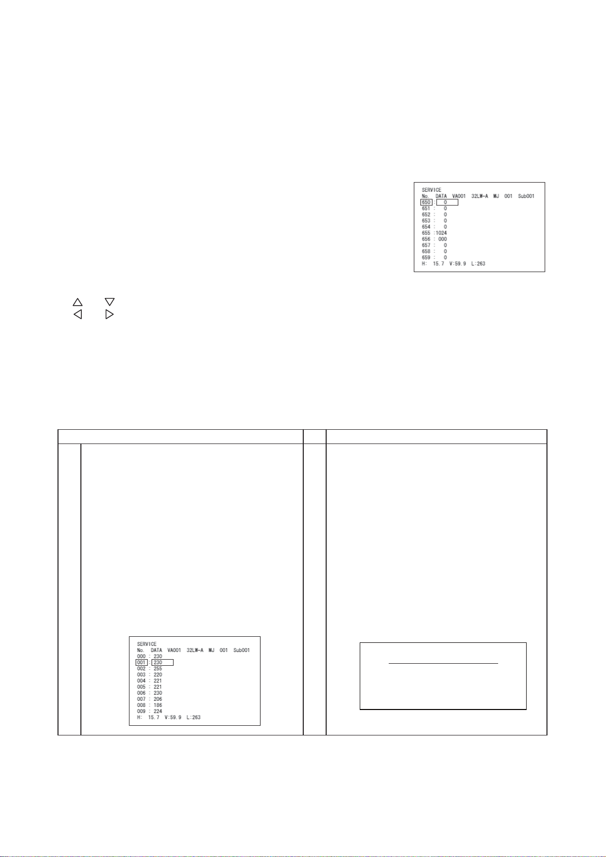
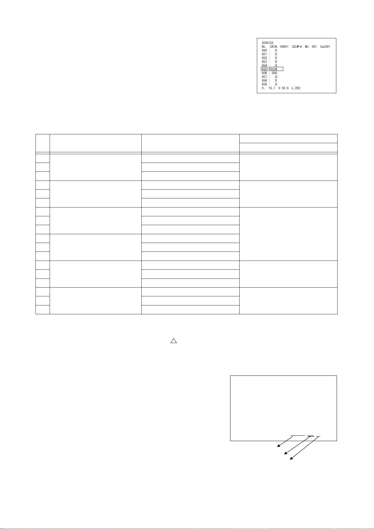
5.2.1 Accumulation time for Panel (hours)
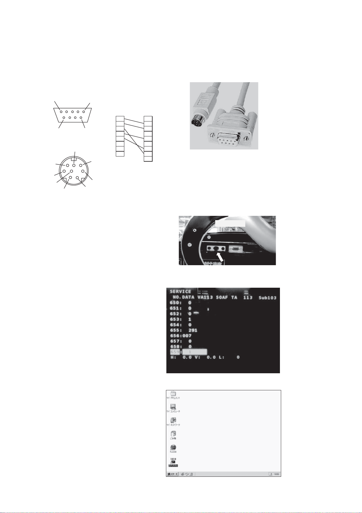
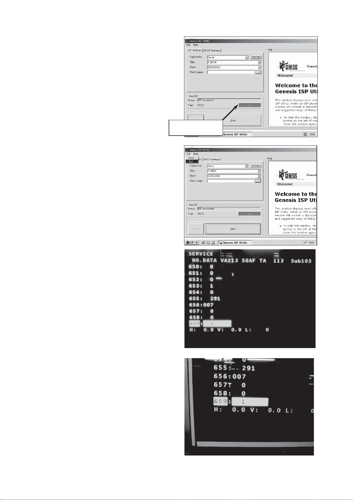
The value of No.655 shows accumulated time (hours).
Reset when the value of No.654 is changed to “1” and “OK” button pushed.
5.2.2 Renew
(1) Change No.659 of the service adjustment menu from “0” to “1” and push
the “OK” button.
The picture will disappear and the initialisation will start.
(2) About 2 seconds later, the initialisation will finish and the picture will appear again.
Do not turn of the power until the picture appears again.
(3) Set adjustment item No.630 to the data in the following table for each model.
No. Destination
1
Japan
3 UT42-BX700J
4
USA
6 UT42X902
7
8 UT37MX70U
9 UT42MX70U
10
11 UT37MX70E
12 UT42MX70E
13
15 UT42-MX700A
16
18 UT42-MX708C
Europe (UK)
Europe
(Continent)
Asia
China
Model
Name
UT32-BH700J
UT32X802
UT32MH70U
UT32MH70E
UT32-MH700A
UT32-MH08C
Adjustment number
630: Custom Setting
42 UT37-BX700J
65 UT37X902
7
014 UT37-MX700A
317 UT37-MX08C
5.2.3 Factory Reset
(1) Turn off power. (Power indicator: Red)
(2) Turn on power while keeping pushed the “ “ button for 5 seconds or more.
5.3 Checking the software version
The software version is displayed on Setup (HDMI/Composite) menu.
Setup
Video Power Save Off
RGBInput Composite
Color System Auto
Select On/Off Return
VM200-20000-1
Main software ver.
Sub software ver.
Destination no.
Europe 07
Asia 00
China 03
USA 06
Japan 04
11
UT32-MH70U/E / UT37-MX70U/E / UT42-MX70U/E (D8MW)
Instruction in software renewal
After software version up, set the following lists for reference.
Main Software Update
In this section, it explains the method of updating Main software.
This procedure should be processed only when it is necessary to update Main software.
1) Prepare Dsub9pin-MiniDin8pin cable.
5
9
D sub 9pin
6
3
4
1
Mini Din 8pin
1
Mini Din 8pinD sub 9pin
1
2
6
7
8
5
2
37
4
5
64
7
82
9
8
6
5
3
1
2) Connect MiniDin8pin plug to Service terminal.
bottom view
3) Press hold [Menu], [Recall] and [Return]
button on the remote controller until
appear the adjustment mode menu.
Select RS232C SW.
• Focus on No.653(RS232C SW).
• Press Right key (0 -> 1)
• Press “OK”.
4) Double click "ISP Utility" icon.
Double Click
12
UT32-MH70U/E / UT37-MX70U/E / UT42-MX70U/E (D8MW)
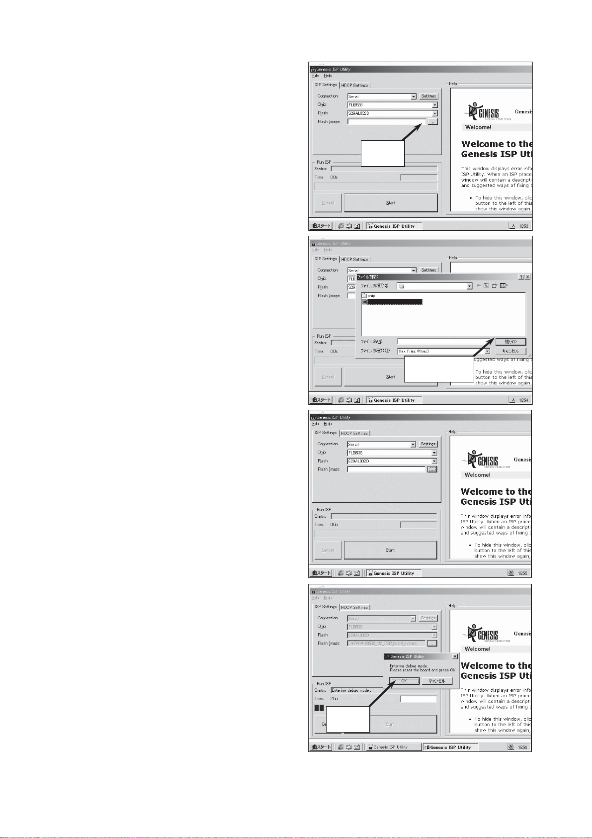
5) Select
Connection : Serial,
Chip : FLI8538,
Flash : S29AL032D,
and click Flash Image select button.
6) Select the new software
ex) ("D8M_VM200.hex")
Click
and click "Open".
7) Click "Start".
Then execute Erase, Program and
Verify.
D8M
D8M_VM200.hex
D8M_VM200.hex
Click Open
C:¥D8M_VM200.hex
8) Click "OK".
Click
13
UT32-MH70U/E / UT37-MX70U/E / UT42-MX70U/E (D8MW)
9) Wait about 200 seconds until
"ISP successful" appears.
(And appear Green display.)
10) Exit ISP Utility.
11) Turn off the TV set. (Unplug AC lead.)
12) Turn on the TV set again. (Connect AC lead.)
C:¥D8M_VM200.hex
Green display
C:¥D8M_VM200.hex
13) Press hold [Menu], [Recall] and [Return]
button on the remote controller until
the adjustment mode menu appears.
14) Focus on No.659 (EEPROM RENEW
operation) .
15) Press Right key (0 -> 1),
16) Press “OK”.
14
UT32-MH70U/E / UT37-MX70U/E / UT42-MX70U/E (D8MW)
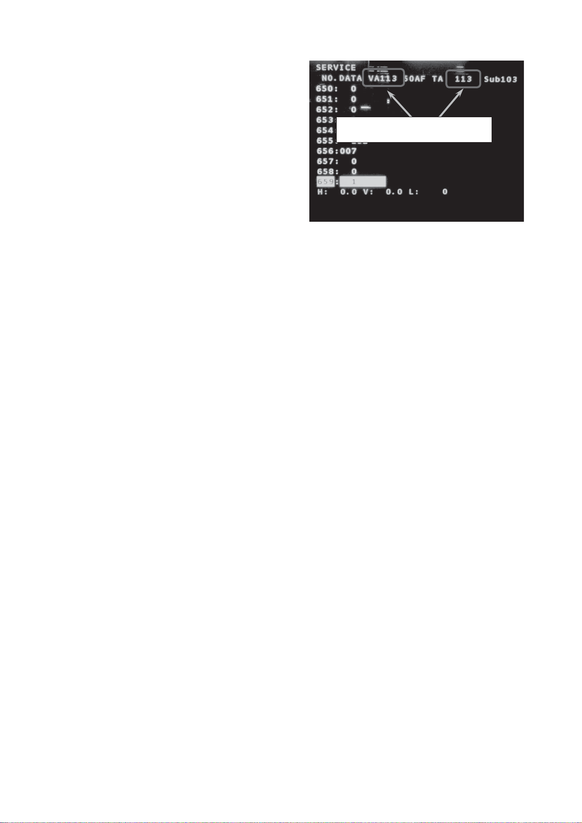
17) Wait until short blanking.
Then the value of No.659 will be changed to “0”.
(Finish EEPROM RENEW operation)
Both numbers should be same
18) Press VOLUME UP/DOWN and the cursor UP/DWON button.
• Focus on No.630 (Custom tuning). 0: ASIA, 3:CHINA, 4:JAPAN, 6:N-AMERICA, 7:EUROPE.
• Press LEFT/Right key and select an appropriate value.
• Press “OK”.
• Press “MENU” key and exit the adjustment mode.
19) Press hold [Menu], [Recall] and [Auto] button on the remote controller
for more than 5 seconds. (Start FACTORY RESET)
20) Turn off the TV set and remove MiniDin9pin connector.
15
UT32-MH70U/E / UT37-MX70U/E / UT42-MX70U/E (D8MW)
Sub Software Update
In this section, the method of updating Sub software is explained.
This procedure should be used only when it is necessary to update Sub software.
1) Turn off the TV set power.
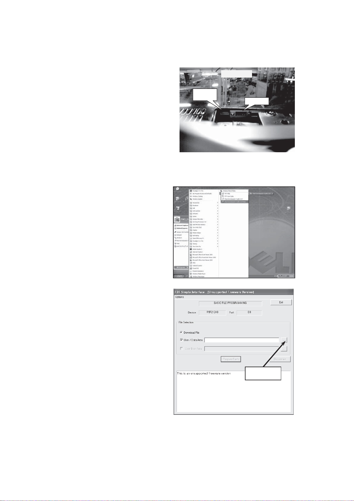
2) Connect E8 or E8a and PC with USB
connection cable.
3) Connect the E8 or E8a to connector
PM02:ZH-10pin.
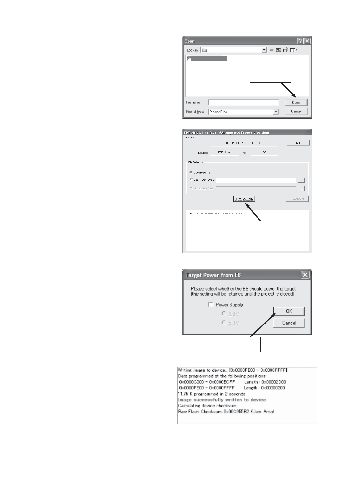
4) Start “Flash Development Toolkit 4.00 Basic”.
(Start > All Program > Renesas > Flash Development Toolkit 4.00 > Flash Development Toolkit 4.00 Basic)
㪧㪤㪇㪉
㪺㫆㫅㫅㪼㪺㫋㫆㫉
Rear view
㪟㪛㪤㪠
5) Select a download file. (ex. D8M_SUB_V200.mot)
Click
16
UT32-MH70U/E / UT37-MX70U/E / UT42-MX70U/E (D8MW)
6) Turn On the TV set.
7) Click “Program Flash”.
D8M_Sub_ROM
D8M_SUB_V200.mot
Click
D8M_SUB_V200.mot
C:¥D8M_Sub_ROM¥D8M_SUB_V200.mot
Click
8) Click “OK” without selecting “Power Supply”. (start update)
Click
9) Wait until the message “Image successfully written to device” appears. (Finish Upadate)
(If necessary, verify the Flash Checksum.)
10) Click “Exit”.
11) Turn Off the TV set.
12) Remove the E8 or E8a from the connector PM02.
13) Turn On the TV set.
17
UT32-MH70U/E / UT37-MX70U/E / UT42-MX70U/E (D8MW)
6. Troubleshooting
Burn-in mode
This mode displays the test patterns of single colour rasters in turn. These signals are from the built-in generator of the panel. It can be presumed that the panel has a fault when the screen of Burn-in mode is abnormal.
To activate the mode, use the remote control with the set turned on.
(1) Set the service adjustment mode.
(2) Change No.646 from “0” to “1”. After a few second, the burn-in picture appears.
(3) To escape this mode, change No.646 from “1” to “0”.
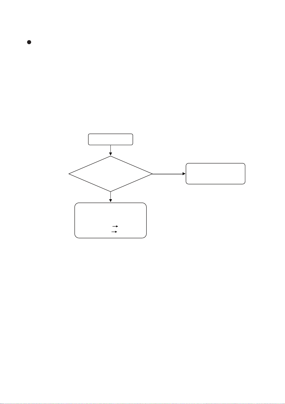
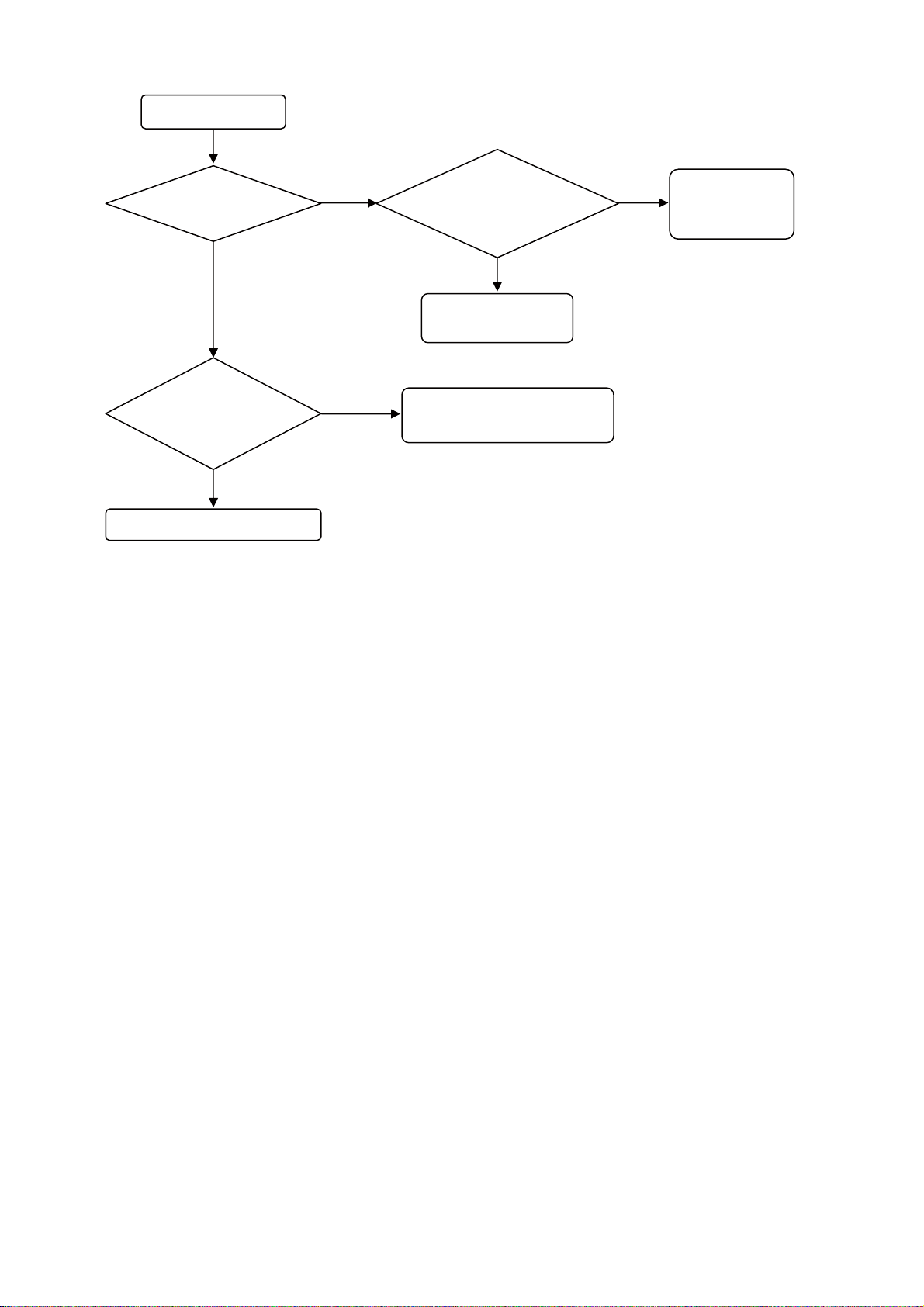
[no picture, no sound]
ԘLED does not light.
Is the voltage of
pin 5 (+5.4V) of CNPS
(power supply unit)
normal?
Yes
Main Board or Terminal
Board fault.
Picture fault Go to “A”
Sound fault Go to “B”
No
Main Board or Power
Supply Unit fault.
Please change.
18
UT32-MH70U/E / UT37-MX70U/E / UT42-MX70U/E (D8MW)
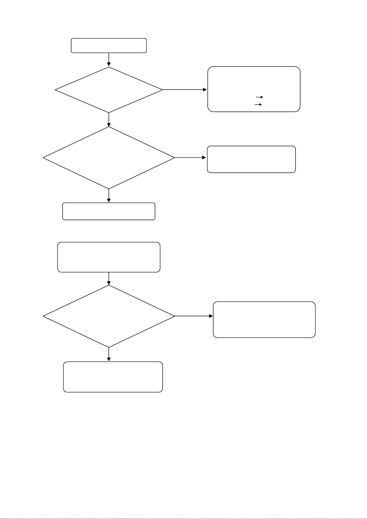
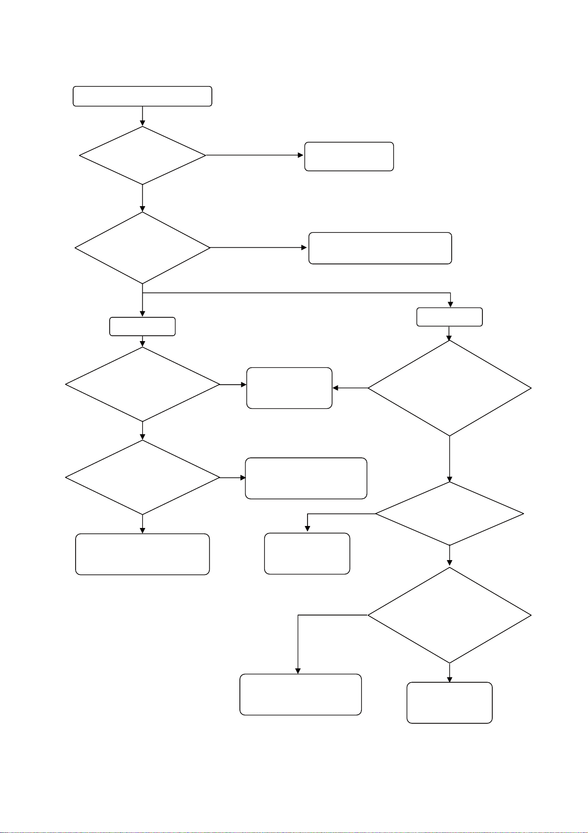
ԙLED lights Green.
Is the burn-in
mode normal?
No
Are the voltages of
pins 1-5 of CNPP1 and pins 1-5 of
CNPP2 (power supply unit) normal?
Normal voltage is +24V.
Yes
Yes
No
Main Board or Terminal
Board fault.
Picture fault Go to “A”
Sound fault Go to “B”
Power Supply Unit fault.
Please change.
Go to # 1
ԚAfter a few seconds, lights
Red even if power is turned on.
Main PCB -- Inverter PCB
PPO1(pin 10) -- CN2(pin 12)
PPO1(pin 11) -- CN2(pin 14)
Are these connected?
Yes
Main Board or LCD Panel
(including Inverter Board) fault.
Please change.
No
Power Supply Unit fault.
Please change.
Or please check ELCD2 connector
or EPS connector.
19
UT32-MH70U/E / UT37-MX70U/E / UT42-MX70U/E (D8MW)
# 1
Does the backlight
turn on?
No
Is there a voltage
at pin 9 of CNPS
(Power supply unit)?
Yes
Inverter Board fault.
Yes
No
Are the voltages of
pin 1-4 (+12V) of PDO1
(Main PCB) normal?
Yes
LCD Panel Module
fault.
Main Board fault.
Please change.
No
Main Board
fault.
Please change.
20
UT32-MH70U/E / UT37-MX70U/E / UT42-MX70U/E (D8MW)
A : Picture Troubleshooting
No picture, no colour or dark
Check the picture menu.
Are there problems?
No
Are the voltages of
pin 7 and 9 (+5V) of PV01
(Main PCB) normal?
Yes
RGB Input
Are there
signals (R,G,B,H,V) at
CE12-CE14,RE49 and
RE50 on Main PCB?
No
Yes
No
Yes
IA01 fault
on Main Board.
Please change.
Adjust the picture
menu.
IR/PW-SW Board fault.
Please check EISP connector
Yes
signals(R(8bit),G(8bit),
B(8bit),H,V,DE,CLK) at
RH33,RH35,RH37 and
RH39 on Main PCB?
HDMI Input
Are there
Are there
signals(R,G,B,H,V) at
CE06-CE08 and
IW01(pin1, 13) on Main
PCB?
No
EFFC Connector on Terminal
Board or PW01 on Main Board
fault.
Yes
QE01-QE03 or IE01 fault
on Main Board.
Please change.
IH01 fault on the
Main Board.
Please change.
Q001, GH01 or DH034
fault on Main Board.
Please change.
No
No
No
Are there signals(TMDS)
at RH60-67 on Main PCB?
Yes
Is there voltage at
pin 18 (+5V) of JH01 (Main
PCB) and is there
voltage(over +2.4V) at
pin19 of JH01?
Yes
IH02 fault
on Main Board.
Please change.
21
UT32-MH70U/E / UT37-MX70U/E / UT42-MX70U/E (D8MW)
B : Sound Troubleshooting
No sound, abnormal sound
Check the signal at the P301
on Terminal Board.
Is there signal
Change Terminal PCB
Has it been
improved?
No
Change EFFC cable
Has it
improved?
No
Change Main Board
Yes
Yes
Yes
Terminal Board
fault.
EFFC Cable
fault.
Change speaker.
Has it been
improved?
No
Change EISP cable
Yes
Speaker
fault.
22
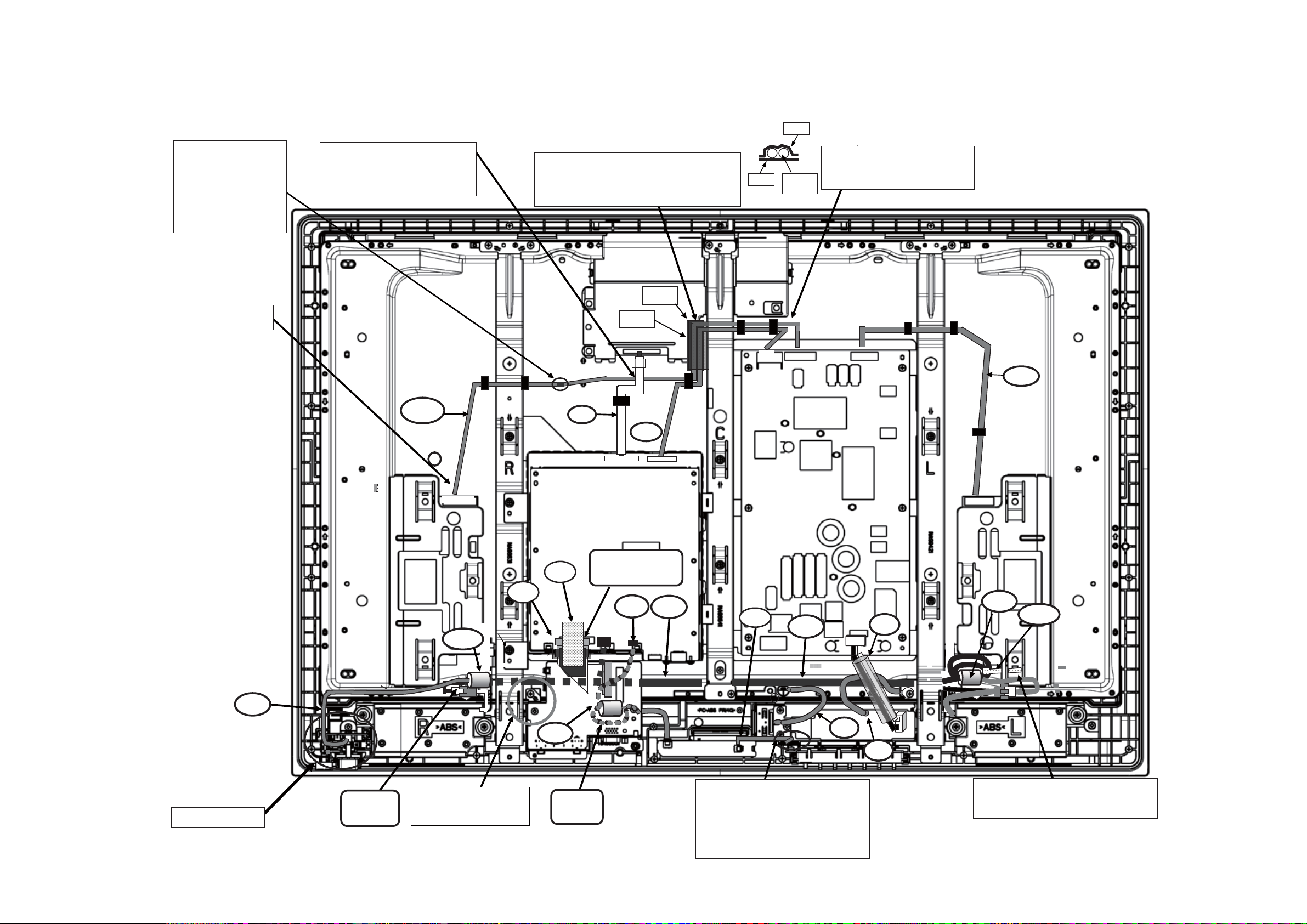
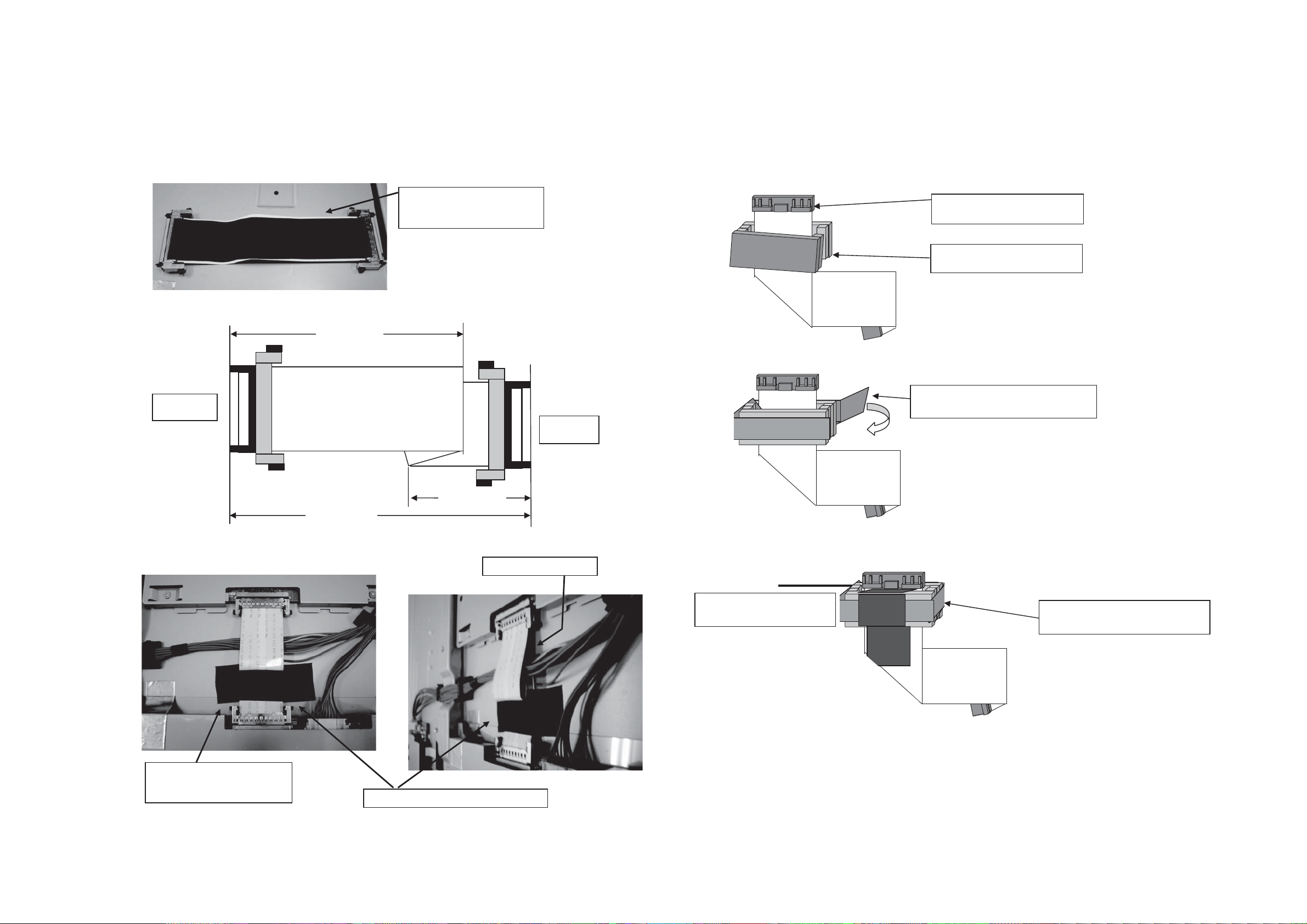
7. Wiring diagram
UT32-MH70U/E Wiring diagram-1
UT32-MH70U/E / UT37-MX70U/E / UT42-MX70U/E (D8MW)
#266
Do the styling so
that the binding tape
of “ELCD3” does
not pass the upper
the frame. (Prevent it
from touching with the
back-cover.)
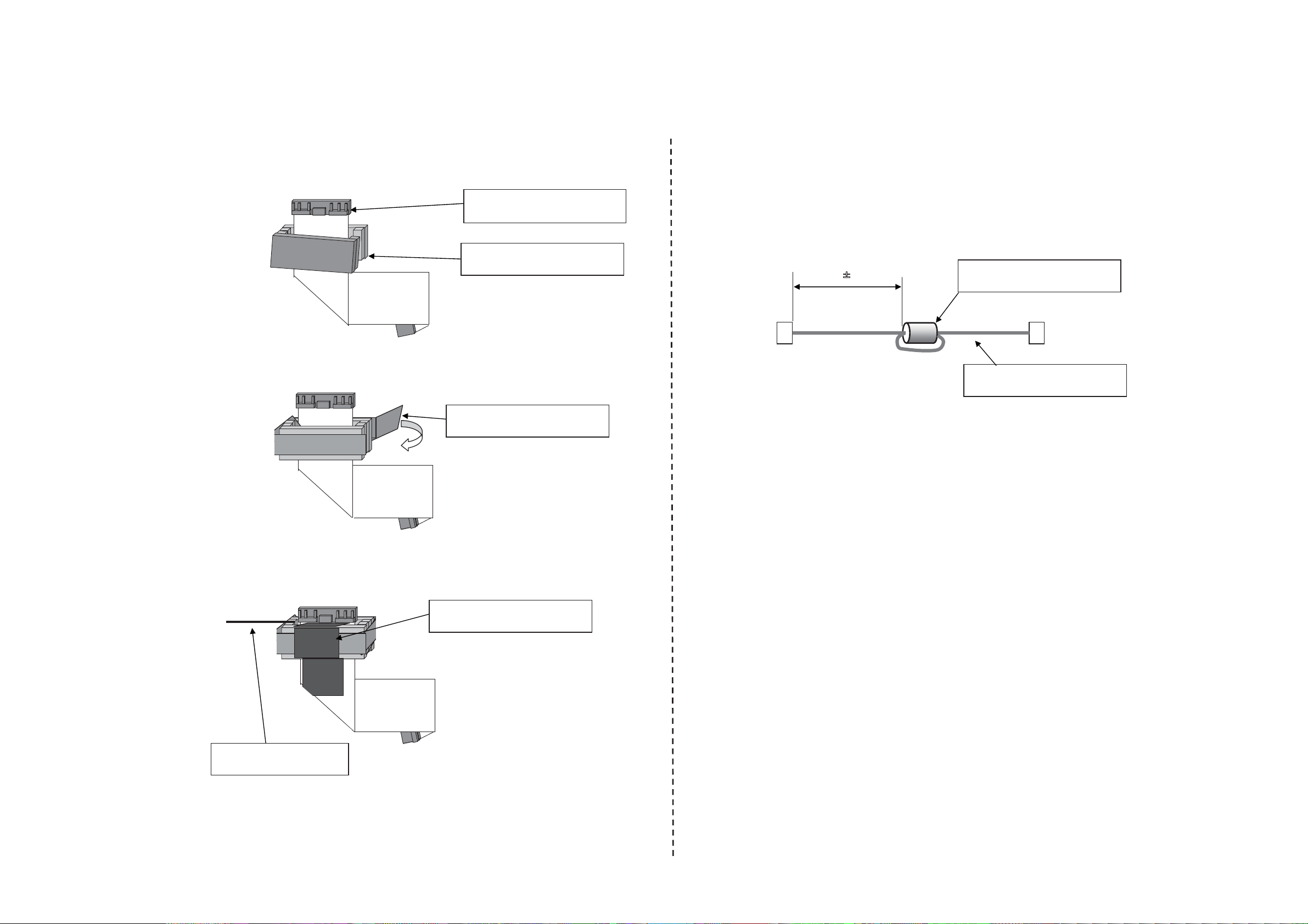
Insert securely.
1) Insert the white tape side of
"ECN" in the T-com board.
2) “ECN" must pass on “ELCD3”.
*Refer to photo 1 (page80)
'.%&
1) Stick the tape(#246 Nitto tape p#944545W)
to the shielding case of the T-CON board.
2) Put “EPS" and “ELCD3” on the tape(#246).
3) Stick the tape(#266 Nitto tape) on that.
'%0
'25
#264
ELCD3
EPS
Do the styling so that the wire
does not pass the upper part of
the shielding case.
'.%&
'+52
IR/POW SW board
RKP
Detail-1(page79)
Photo2(page80)
'((%
'.5
'+52
'-.
'+52
'27
052-
052-
052-
'
'
Fix with SK binder(#NSPK) so that the
wire of “EISP" does not touch the filter
board. *Refer to photo5 (page81)
Photo 4
(page80)
Please do not damage the
cable when exchanging
the Terminal board.
0'.5
Detail-2
(page79)
The wire of “EKL" must pass between
the KEY_SW board and the case and
allow loosening.
(It is to prevent the electric wire being
pinched when tightening up a screw.)
*Refer to photo3(page80)
23
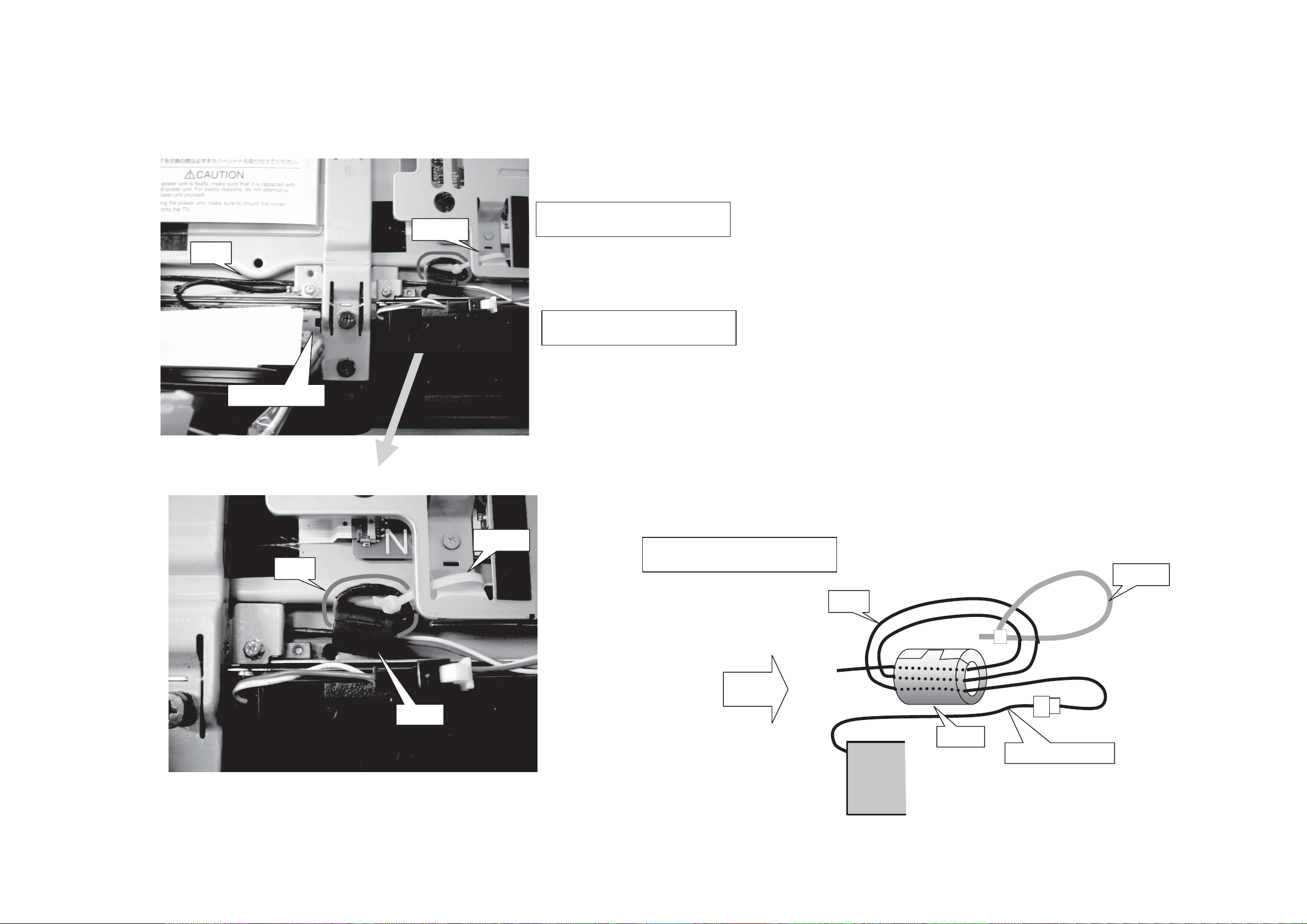
UT32-MH70U/E Wiring diagram-2
UT32-MH70U/E / UT37-MX70U/E / UT42-MX70U/E (D8MW)
[ Detail-1 Pre-operation ] [ Detail-2 Pre-operation ]
(1) Set the ferrite core (N001) in EFFC.
57/+ 57/+ 57/+
57/+ 57/+ 57/+
57/+ 57/+ 57/+
57/+ 57/+ 57/+
EFFC PRW50FC0R5-131-20861
(p #: EK01902)
N001 MAG-FSRC400120RTF10T
(p #: GX00771)
(1) Set the ferrite core (NELS) in ELS. 1turn.
Pass the terminal board under.
60mmr
Main board side
(2) Wrap the tape(#WN01) around the ferrite core(N001).
#WN01 Nitto tape No.5 W=9mm
(P#9449507W) L=100mm
5mm
NELS MAG K5CRC12X15X7-MB2
(p㧏㧦GX00738)
ELS CO-06C-C1R0-201-LOCK
(p㧏㧦EF24946)
(3) Fix the ferrite core(N001) with the tape(#WN02).
Set the ferrite core(N001) in the
connector edge side.
57/+ 57/+ 57/+
57/+ 57/+ 57/+
57/+ 57/+ 57/+
57/+ 57/+ 57/+
57/+ 57/+ 57/+
57/+ 57/+ 57/+
57/+ 57/+ 57/+
57/+ 57/+ 57/+
#WN02 Nitto tape No.5 W=25mm
(P#9449538W) L=35mm
24
UT32-MH70U/E Wiring diagram-3
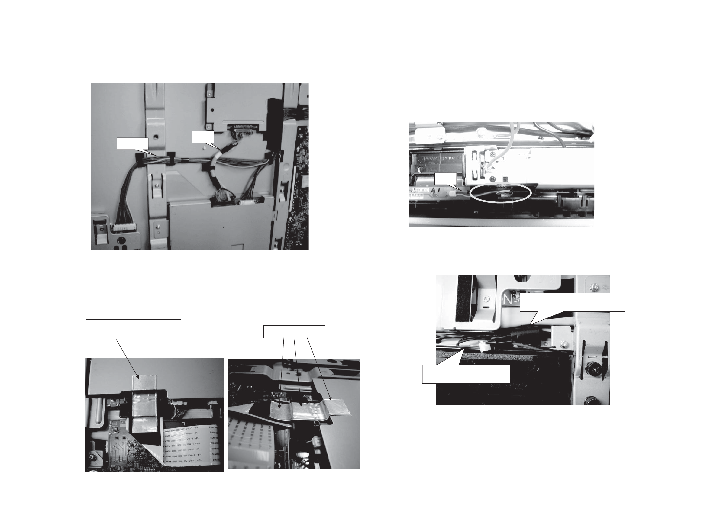
(1) “ECN" must pass on “ELCD3”.
ELCD3
UT32-MH70U/E / UT37-MX70U/E / UT42-MX70U/E (D8MW)
(3) The electric wire of “EKL" must be pushed between the KEY_SW board and the case,
and allow loosening.
ECN
EKL
(2) How to stick aluminum tape
#360 D8MW SIGNAL SLD TAPE
(p# : MD20801)
(4) Set the ferrite core (NSPK2) in EISP.
NSPK2 MAG K5CRC12X15X7-MB2
(p#:GX00738)
Paste fit without space.
EISP CO-10C-C***-871-ASS
(p#:EF28881)
25
UT32-MH70U/E Wiring diagram-4
K
K
(5) Set the ferrite core (NSPK) in EISP.
EISP
#NSPK
UT32-MH70U/E / UT37-MX70U/E / UT42-MX70U/E (D8MW)
#NSPK SK-binder
(p# : 3763751)
Filter Assembly
EISP
NSP
#NSPK
NSPK MAG K5CRC12X15X7-MB2
(p# : GX00738)
#NSPK SK-binder
(p# : 3763751)
EISP
Double wrap the EISP cable in the core (NSPK).
#NSPK
NSP
NSPK
Speaker cable
Speaker assembly
26
UT37-MX70U/E Wiring diagram-1
UT32-MH70U/E / UT37-MX70U/E / UT42-MX70U/E (D8MW)
Please do not damage the
cable when you exchange
the terminal PWB.
27
UT37-MX70U/E Wiring diagram-2
UT32-MH70U/E / UT37-MX70U/E / UT42-MX70U/E (D8MW)
[Detail-1 and Pre-operation] [Detail-2 and Pre-operation]
(1) Paste the Nitto tape(#ECN) on the backside of ECN(p#EF29004). (1) Set the ferrite core(N001) in EFFC.
#ECN
Nitto tape No.5 W25 L=105mm
(p#9449538W).
(2) Fold as shown in the figure below.
60mmr3mm
(2) Wrap the tape(#WN01) around the ferrite core(N001).
74 #9/ 89 9:( 7
T-CON PCB
side
74 #9/ 89 9:( 7
74 #9/ 89 9:(
74 #9/ 89 9:(
90mmr2mm
#9/
#9/
#9/
4 #9/
45mmr3mm
Main PCB
side
EFFC PRW50FC0R5-131-20861
(p#:EK01902)
N001 MAG-FSRC400120RTF10T
(p#:GX00771)
#WN01 Nitto tape NO.5 W9 100m
(p#:9449507W)
(3) Connect to the T-CON PCB. (3) Fix the ferrite core(N001) with the tape(#WN02).
#334
Nitto tape No.5 W25 L=60mm
(p#9449538W).
Paste the tape to the Main PCB side.
Float the T-CON side.
Set the ferrite core(N001) in the
connector edge side.
#WN02 Nitto tape No.5 W25
(P#9449538W) L=35mm
28
UT32-MH70U/E / UT37-MX70U/E / UT42-MX70U/E (D8MW)
UT37-MX70U/E Wiring diagram-3
[Detail-3 and Pre-operation] [Detail-4 and Pre-operation]
(1) Set the ferrite core (NSPK) in EISP. 1turn.
50mm±5mm
EISP
NSPK: MAG K5CRC12X15X7-MB2 (p#GX00738)
(2) Fasten with the SK-binder(#NSPK) near NSPK.
#NSPK SK-binder
(p#:3763751)
NSPK MAG K5CRC12X15X7-MB2
(p#GX00738)
(1) Set the ferrite core(NELS) in ELS. 1turn.
Pass the terminal board under.
60mm±5mm
Main board side
[Detail-5]
NELS MAG K5CRC12X15X7-MB2
(p#:GX00738)
ELS CO-06C-C1R0-201-LOCK
(p#:EF24946)
#360 D8MW SIGNAL SLD TAPE
(p#:MD20801)
Paste fit without space.
29
 Loading...