


PRODUCT NAME
Hitachi Cordless Radio
Model UR 18DSL2
LIST No.
UR 18DSL2: J862
Sep. 2013
International Sales Division
U
TROUBLESHOOTING GUIDE ---------------------------------------------------------------------------------------------- 1
REPAIR GUIDE ---------------------------------------------------------------------------------------------------------------- 4
ST A NDARD REPAIR TIME (UNIT) SCHEDULES --------------------------------------------------------------------10
CONTENTS
Page

-9-
Trouble Check method Check result Cause Corrective action
(1) Power
cannot
be turned
on.
(i) Set a normally charged battery in the
Model UR 18DSL2, and check whether
power can be turned on.
Power can be turned on by
both methods (i) and (ii).
Battery is abnormal or depleted. Charge the battery or replace it with a normal battery.
AC-Adapter [501] is abnormal. Replace AC-Adapter [501] with a new one.
Power cannot be turned on
by both methods (i) and (ii).
Go to the next check. Go to check method (1)-(iii).
(ii) Connect AC-Adapter [501] to the Model
UR 18DSL2, and check whether power
can be turned on.
Power can be turned on by
either method (i) or (ii).
Terminal Ass'y (E) [34] is abnormal. Replace Terminal Ass'y (E) [34].
(iii) Disassemble the Model UR 18DSL2,
and then check whether all connectors
are properly connected.
Some connectors are
disconnected.
Same as on the left. Connect the disconnected connectors.
All connectors are properly
connected.
Go to the next check. Go to check method (1)-(iv).
(iv) Set the battery and check voltage at
the 3-pin connectors. * Perform the
same check on the red (+) and blue (-)
pins to connect the AC adapter.
Measured voltages are
nearly the same as those on
the battery and AC adapter.
Controller PCBA [17] and Function
PCBA [20] are abnormal.
Replace Controller PCBA [17] and Function PCBA
[20].
Voltage cannot be
measured.
Go to the next check. Go to check method (1)-(v).
(v) Check whether Fuse (250 V-2 A) [33] is
blown.
Fuse (250 V-2 A) [33] is
blown.
Same as on the left.
Replace Fuse (250 V-2 A) [33].
Fuse (250 V-2 A) [33] is not
blown.
Go to the next check. Go to check method (1)-(vi).
(vi) Replace Terminal Ass'y (E) [34], and
then check whether power can be
turned on.
Power can be turned on.
Terminal Ass'y (E) [34] is abnormal. (Replace Terminal Ass'y (E) [34].)
Power cannot be turned on.
Controller PCBA [17] and Function
PCBA [20] are abnormal.
Replace Controller PCBA [17] and Function PCBA
[20].
(2) No
sound
is output.
(i) Turn the volume dial. Abnormal noise is produced
w
hen turning the dial.
Controller PCBA [17] and Function
PCBA [20] are abnormal.
Replace Controller PCBA [17] and Function PCBA
[20].
Neither noise nor sound is
produced.
Go to the next check. Go to check method (2)-(ii).
(ii) Disassemble the Model UR 18DSL2,
and then check whether all connectors
are properly connected.
Some connectors are
disconnected.
Same as on the left. Connect the disconnected connectors.
All connectors are properly
connected.
Go to the next check. Go to check method (2)-(iii), or replace Terminal
Ass’y (E) [34].
(iii) Measure speaker resistance with
multimeter.
Measured resistance is
about 8Ω
(
normal value).
Go to the next check. Go to check method (2)-(iv).
Measured resistance largely
deviates from 8Ω.
Speakers are abnormal.
Replace Front Housing Ass'y [8].
(iv) Use multimeter to check whether any
internal wires are broken.
Some internal wires are
broken.
Some internal wires are broken. Replace broken internal wires.
No internal wire is broken.
Controller PCBA [17] and Function
PCBA [20] are abnormal.
Replace Controller PCBA [17] and Function PCBA
[20].
TROBLESHOOTING GUIDE
-1-

-10-
Trouble Check method Check result Cause Corrective action
(3) AM radio
broadcast
cannot be
received.
(i) Put the Model UR 18DSL2 in a place
without surrounding walls or buildings
blocking radio waves, and without
noise-producing equipment (e.g.,
fluorescent lamp, personal computer,
battery charger, compressor), tune in an
easily received frequency, and then
adjust orientation of the Model
UR 18DSL2.
The broadcast can be
received.
Radio waves are blocked by surrounding
walls or other structures. Orientation of the
Model UR 18DSL2 (built-in antenna) is
inappropriate.
Move the Model UR 18DSL2 to a better reception
environment (e.g., near a window), and then adjust
orientation of the Model UR 18DSL2.
Reception is affected by noise from
nearby equipment.
Keep the Model UR 18DSL2 away from the noise-source
equipment.
The broadcast cannot be
received.
Go to the next check. Go to check method (3)-(ii).
(ii) Disassemble the Model UR 18DSL2, and
then check whether all connectors are
properly connected.
Some connectors are
disconnected.
Same as on the left. Connect the disconnected connectors.
All connectors are
properl
y
connected.
Controller PCBA [17] and Function PCBA
[20] are abnormal.
Replace Controller PCBA [17] and Function PCBA [20].
(4) FM radio
broadcast
cannot be
received.
(i) Put the Model UR 18DSL2 in a place
without surrounding walls or buildings
blocking radio waves, and without
noise-producing equipment (e.g.,
fluorescent lamp, personal computer,
battery charger, compressor), tune in an
easily received frequency, and then
adjust orientation of Rubber Antenna [1].
The broadcast can be
received.
Radio waves are blocked by surrounding
walls or other structures. Orientation of
Rubber Antenna [1] is inappropriate.
Move the Model UR 18DSL2 to a better reception
environment (e.g., near a window), and then adjust
orientation of Rubber Antenna [1].
Reception is affected by noise from
nearb
y
equipment.
Keep the Model UR 18DSL2 away from the noise-source
equipment.
The broadcast cannot be
received.
Go to the next check. Go to check method (4)-(ii).
(ii) Disassemble the Model UR 18DSL2, and
then check whether all connectors are
properly connected.
Some connectors are
disconnected.
Same as on the left Connect the disconnected connectors.
All connectors are
properl
y
connected.
Controller PCBA [17] and Function PCBA
[20] are abnormal.
Replace Controller PCBA [17] and Function PCBA [20].
(5) Music cannot
be played in
AUX mode.
(i) Connect the music player using the
proper connection cable, and then check
whether music can be played.
Music can be played. The connection cable is broken. Ask the customer to check whether the connection cable is
broken.
Music cannot be played. Go to the next check. Go to check method (5)-(ii).
(ii) Connect a normal mobile music player,
and then check whether music can be
played.
Music can be played. The mobile music player is faulty. Ask the customer to check whether the mobile music
pla
y
er is faulty.
Music cannot be played. Go to the next check. Go to check method (5)-(iii).
(iii) Disassemble the Model UR 18DSL2,
and then check whether all connectors
are properly connected.
Some connectors are
disconnected.
Same as on the left. Connect the disconnected connectors.
All connectors are
properl
y
connected.
Go to the next check. Go to check method (5)-(iv).
(iv) Replace USB PCBA [59], and then
check whether music can be played.
Music can be played.
USB PCBA [59] is abnormal. (Replace USB PCBA [59].)
Music cannot be played.
Controller PCBA [17] and Function PCBA
[20] are abnormal.
Replace Controller PCBA [17] and Function PCBA [20].
-2-

-11-
Trouble Check method Check result Cause Corrective action
(6) No sound is
output from
headphone.
(i) Connect a normal headphone, and then
check whether sound is output.
Sound is produced. The headphone is faulty. Ask the customer to check whether the headphone is
faulty.
Sound is not produced. Go to the next check. Go to check method (6)-(ii).
(ii) Disassemble the Model UR 18DSL2,
and then check whether all connectors
are properly connected.
Some connectors are
disconnected.
Same as on the left. Connect the disconnected connectors.
All connectors are
properly connected.
Go to the next check. Go to check method (6)-(iii).
(iii) Replace Terminal Ass’y (E) [34], and
then check whether sound is produced.
Sound is produced.
Terminal Ass’y (E) [34] is abnormal. (Replace Terminal Ass’y (E) [34].)
Sound is not produced.
Controller PCBA [17] and Function PCBA
[20] are abnormal.
Replace Controller PCBA [17] and Function PCBA [20].
(7) Mobile phone
cannot be
charged.
(i) Connect the mobile phone with the
normal charging cable, and then check
whether the mobile phone can be
charged.
The mobile phone can
be charged.
The charging cable is broken. Ask the customer to check whether the charging cable is
broken.
The mobile phone
cannot be charged.
Go to the next check. Go to check method (7)-(ii).
(ii) Connect a normal mobile phone, and
then check whether the mobile phone
can be charged.
The mobile phone can
be charged.
The mobile phone is faulty. Ask the customer to check whether the mobile phone is
faulty.
The mobile phone
cannot be charged.
Go to the next check. Go to check method (7)-(iii).
(iii) Disassemble the Model UR 18DSL2,
and then check whether all connectors
are properly connected.
Some connectors are
disconnected.
Same as on the left. Connect the disconnected connectors.
All connectors are
properly connected.
Controller PCBA [17] and Function PCBA
[20] are abnormal.
Replace Controller PCBA [17] and Function PCBA [20].
(8) A switch or
Dial [6] is
disabled.
(i) Replace Controller PCBA [17], and then
check whether the switch or dial is
enabled.
The switch or dial is
enabled.
Controller PCBA [17] is abnormal. (Replace Controller PCBA [17].)
The switch or dial is
disabled.
Go to the next check. Go to check method (8)-(ii).
(ii) Replace Function PCBA [20], and
check whether the switch or dial is
enabled.
The switch or dial is
enabled.
Function PCBA [20] is abnormal. (Replace Function PCBA [20].)
-3-

-4-
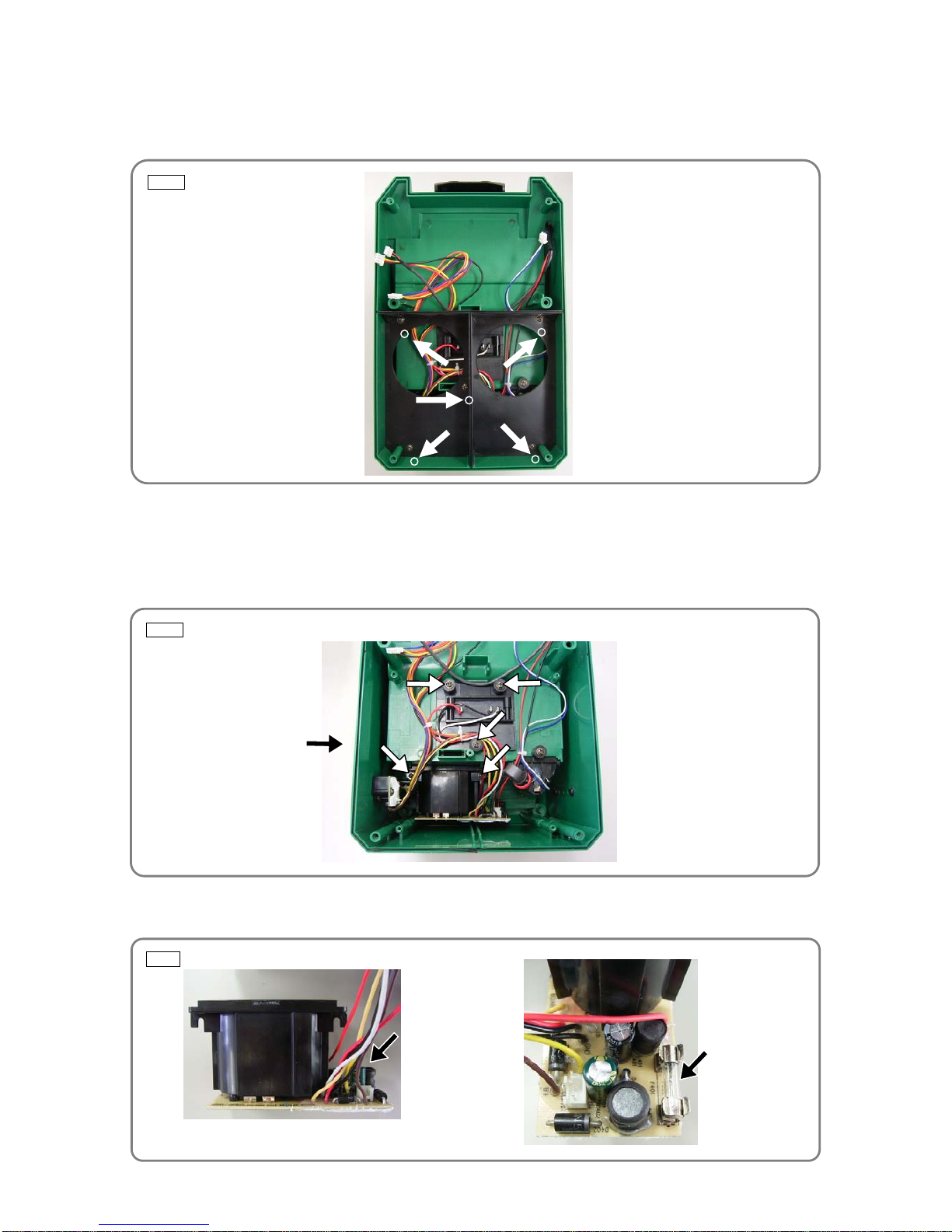
Fig. 1 • Inside the front housing
[Bold] numbers in the descriptions below correspond to item numbers in the parts list for the Model
UR 18DSL2. The rechargeable battery must be removed from the Model UR 18DSL2 before disassembling
or repairing the Model UR 18DSL2.
1. Disassembly and reassembly of the front and back housings
<<Disassembly>>
(1) Remove the four Machine Screws M4 x 15 (Black) [3] from the front of the product.
(2) Open the Back Door [75] and remove the two Machine Screws M4 x 15 (Black) [3] from the back of the
Back Housing [26].
NOTE: Perform this operation carefully because multiple internal wires are connected between
the front and back housings.
(3) Remove the four internal wire connectors (Fig. 1) from Function PCBA [20] in the front housing. Then
you can fully separate the front housing from the back housing.
<<Reassembly>>
Reverse the disassembly procedure. Note the following at reassembly:
(1) The 3-pin connectors are shaped differently to prevent wrong installation. Do not forcibly connect the
connectors if their shapes do not match each other. (The upper 3-pin connector has red, black, and white
internal wires. The lower 3-pin connector has blue, red, and yellow internal wires.)
(2) When connecting each connector, be sure to fit it fully into the receptacle.
(3) The Front O-ring [24] is set between the mating surfaces of the front and back housings. Be careful to
prevent any part of the O-ring from protruding.
(4) Be careful to prevent internal wires from being caught between other parts.
REPAIR GUIDE
Four connectors to remove
3-pin connector (upper)
3-pin connector (lower)
Disassembly and reassembly
-5-
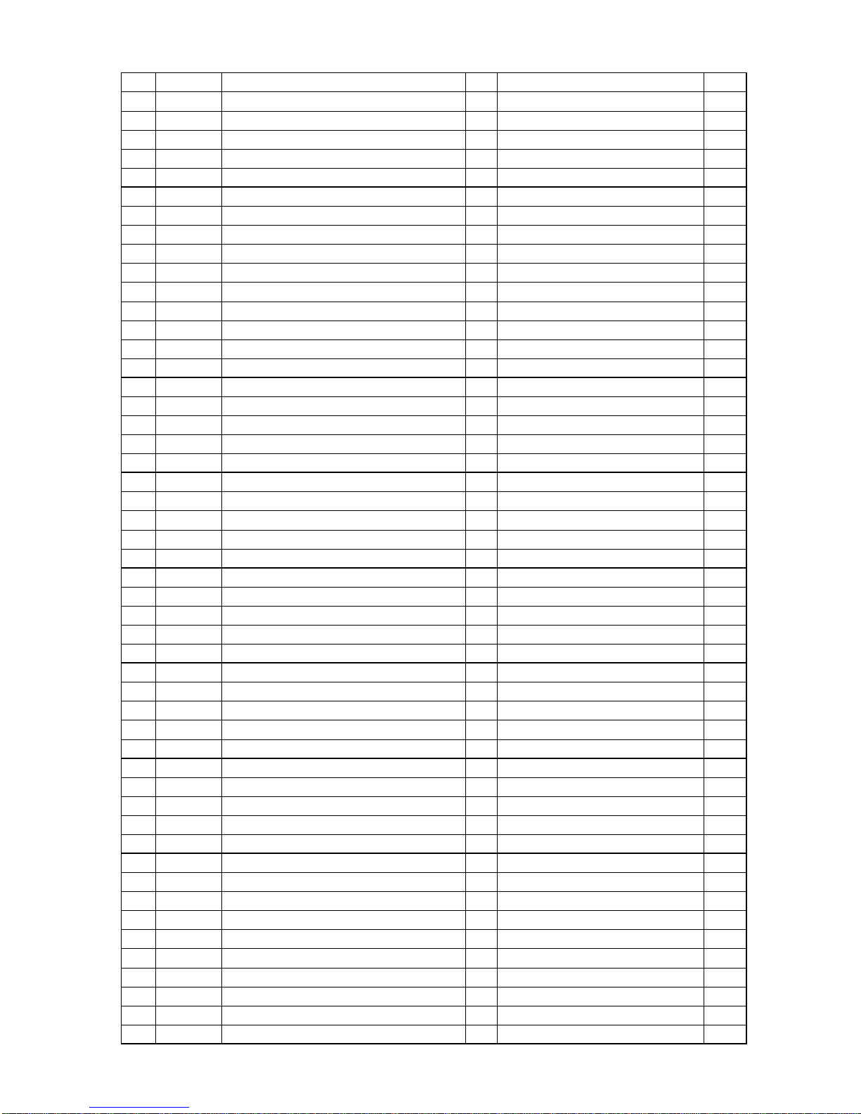
Fig. 2 • Inside the back housing
Fig. 3 • Bottom of inside the back housing
Fig. 4
2. Disassembly and reassembly of the back housing
<<Disassembly>>
(1) Remove the five Machine Screws (W/Flange) M3 x 10 (Black) [9]. Then you can remove the Speaker
Back Cover [23]. (Fig. 2)
(2) Remove the Speaker Back Cover [23]. Then you can see Terminal Ass'y (E) [34] and AA Battery Box
[36]. (Fig. 3)
(3) Remove the five Machine Screws (W/Flange) M3 x 10 (Black) [9] (indicated by arrows in Fig. 3) and the
three Machine Screws (W/Flange) M3 x 10 (Black) [9] from the Jack Cover (L) [27] located externally on
the left side. You can now remove Terminal Ass'y (E) [34].
(4) The Fuse (250 V-2 A) [33] is located to the right of the EB battery box in Terminal Ass'y (E) [34], and can
be easily replaced.
Remove the five Machine Screws
(W/Flange) M3 x 10 (Black) [9] fixing the
Speaker Back Cover [23].
Eight Machine Screws (W/Flange)
M3 x 10 (Black) [9] fixing the
Terminal Ass'y (E) [34]
Three Machine Screws
(W/Flange) M3 x 10
(Black) [9]
Fuse (250 V-2 A) [33]
EB battery box

-6-
Fig. 5
<<Reassembly>>
Reverse the disassembly procedure. Note the following at reassembly:
(1) When reassembling Terminal Ass'y (E) [34], be sure to mount the jack located internally on the left side
prior to the EB battery box. (The two parts cannot be assembled if mounted in reverse order.)
(2) Be careful to prevent internal wires from being caught between other parts.
3. Disassembly and reassembly of the front housing
Removing the function PCBA
<<Disassembly>>
(1) Remove the three connectors, and then remove the four Machine Screws (W/Flange) M2.6 x 10 (Black)
[19].
(2) Use a soldering iron to remove internal wires from the speakers.
(3)
Move Function PCBA [20] aside a little, and then remove the Machine Screw (W/Flange) M3 x 10 (Black)
[9] located near the end of the Rubber Antenna [1]. Then you can remove the internal wire connected to
the Rubber Antenna [1]. (Fig. 5)
(4) Remove Function PCBA [20].
<<Reassembly>>
Reverse the disassembly procedure. Note the following at reassembly:
(1) When soldering internal wires on the speakers, carefully check the colors of internal wires for proper
connections.
Right speakers (found on the left in disassembled status): Internal wire colors are red (+) and blue (-).
Left speakers (found on the right in disassembled status): Internal wire colors are white (+) and blue (-).
(2) Do not forget to connect the internal wire to the Rubber Antenna [1].
(3) When connecting each connector, be sure to fit it fully into the receptacle.
Removing the Controller PCBA
<<Disassembly>>
(1) Remove the two Dials [6] from the front of the Front Housing Ass’y [8].
NOTE: Wrap a piece of thick cloth around each Dial [6], and then remove it with pliers or another
tool. Be careful not to damage the Dial [6].
Connectors
Soldered positions
Machine Screw (W/Flange) M3 x 10 (Black)
[9] is located under Function PCBA [20].

-7-
Fig. 6 • Controller PCBA [17] at the top of the front housing
Fig. 7 • Detaching the USB PCBA
(2) Remove the five Machine Screws (W/Flange) M2.6 x 10 (Black) [19]. Then you can remove the
Controller PCBA [17]. (Fig. 6)
<<Reassembly>>
Reverse the disassembly procedure. Note the following at reassembly:
(1) Do not forget to attach the Fibre Washers [18].
(2) Be careful to prevent dust or fingerprints from adhering to the LCD monitor on Controller PCBA [17] and
the transparent window of the Front Housing Ass’y [8].
4. Disassembly and reassembly of the external device storage case
Detaching the USB PCBA
<<Disassembly>>
(1) Remove the four Machine Screws M4 x 15 (Black) [3].
(2) Next, remove one Machine Screw M4 x 15 (Black) [3] on the handle arm cover side.
(3) Remove the two Flange Screws D3 x 6 [60] on the back of the box plate.
(4) Cut off the wire ties and then remove the connector and the magnet.
<<Reassembly>>
Reverse the disassembly procedure. Note the following at reassembly:
(1) Be careful not to allow the internal wires to get pinched.
Five Machine Screws (W/Flange)
M2.6 x 10 (Black) [19]
• Four Machine Screws M4 x 15 (Black) [3]
• One Machine Screw M4 x 15 (Black) [3]
• Lower inside of back housing
• Two Flange Screws D3 x 6 [60]

-8-
Fig. 8 • Detaching the lens plate
Fig. 9 • Rubber antenna
Fig. 10 • Replacing only the receiver of the rubber antenna
Detaching the lens plate
<<Disassembly>>
(1) Remove the four Flat Hd. Screws D2 x 4 (Black) [54].
(2) Remove the Flat Metal Plate [53], Lock Plate (A) [52], and Lock Spring [51].
(3) Bow down the Box Cover [55] and remove the Lens Plate [56].
<<Reassembly>>
Reverse the disassembly procedure.
Replacing only the receiver of the rubber antenna
(1) Remove the screw from the joint, and then divide a new Rubber Antenna [1] unit into the receiver and the
main shaft.
(2) Similarly, disassemble the Rubber Antenna [1] mounted on the Model UR 18DSL2 by dividing it at the
joint. To disassemble the Rubber Antenna [1] mounted on the Model UR 18DSL2, turn the Rubber
Antenna [1] by 90 degrees as shown in the figure below, and then use a screwdriver to remove the screw
fixing the joint from the right side of the Model UR 18DSL2 (having a shaft at least 140 mm long). (Fig. 10)
(3) Replace the receiver of the Rubber Antenna [1] with a new one, and then tighten the screw fixing the
joint.
NOTE: Be careful not to lose the two thin washers mounted at the joint of the Rubber Antenna [1].
Bow down the Box Cover [55] and remove the Lens Plate [56].
Four Flat Hd. Screws D2 x 4 (Black) [54]
Joint Rece iver
Main shaft

-9-
• Connect the AC adapter, sliding-fit type battery, or plug-in type battery to the Model UR 18DSL2, and then
check that the Model UR 18DSL2 can be turned on normally.
• Check that the Model UR 18DSL2 can receive AM radio broadcasts normally
*2
in a good reception
environment.
*1
• Check that the Model UR 18DSL2 can search for AM radio broadcasts normally
*3
in a good reception
environment.
*1
• Check that the Model UR 18DSL2 can receive FM radio broadcasts normally
*2
in a good reception
environment.
*1
• Check that the Model UR 18DSL2 can search for FM radio broadcasts normally
*3
in a good reception
environment.
*1
*1
Good reception environment: A place without walls and buildings that block radio waves and without
nearby equipment (e.g., fluorescent lamp, personal computer, battery charger, compressor) that produces
noise
*2
Reception of a radio wave depends on the direction of the broadcast station and orientation of the antenna.
If a broadcast cannot be received well, try to adjust the orientation of the FM antenna (or orientation of the
Model UR 18DSL2 for AM radio reception).
*3
Searching for a broadcast depends on the direction of the broadcast station and orientation of the antenna.
If a broadcast cannot be properly searched, try to adjust the orientation of the FM antenna (or orientation
of the UR 18DSL2 for AM radio reception).
• While receiving an AM radio broadcast, tap the side of the Model UR18DSL2 with your hand, and then
check that noise does not increase or sound is not interrupted each time you tap the radio. (If noise
increases or sound is interrupted, connectors may be loose or a circuit board may be faulty.)
• While receiving a FM radio broadcast, tap the side of the Model UR 18DSL2 with your hand, and then
check that noise does not increase or sound is not interrupted each time you tap the radio. (If noise
increases or sound is interrupted, connectors may be loose or a circuit board may be faulty.)
Checks after reassembly

-10-
MODEL
Variable
Fixed
10 20 30 40 50 60 min.
UR 18DSL2
General Assembly
Front Housing
Ass’y
TPE
Cover (A)
TPE
Cover (B)
Speaker Cove
r
Back Housing
TPE
Cover (D)
TPE
Cover (C)
Back Door
Work Flow
Function PCBA
Controller
PCBA
Dial
Speaker
Back Cove
r
Terminal (D)
AA Battery Box
Box Cover
Lens Plate
USB PCBA
Handle Box
Handle (L)
Handle (R)
Handle
Rubber
Antenna
STANDARD REPAIR TIME (UNIT) SCHEDULES

Model UR 18DSL2
CORDLESS RADIO
LIST NO. J862
2013· 9 · 27
(E1)
䢢
A
32
31
9
23
29
30
28
3
38
24
33
34
9
35
36
9
25
9
26
3
3
39
27
37
9
9
25
19
14
1
2
3
4
2
5
6
7
8
9
10
11
12
13
21
15
16
17
19
19
20
3
22
3
3
19
18
A

UR 18DSL2
9 - 13
- 2 -
71
3
76
75
3
68
69
69
68
74
78
72
73
70
55
56
62
63
51
52
53
54
58
59
60
61
3
64
65
66
67
3
3
3
57
502
501
3
3
77
PART
S
UR 18DSL2
DESCRIPTION REMARKS
1 335-813 RUBBER ANTENNA 1
2 331-605 GUARD BAR 2
3 331-606 MACHINE SCREW M4 X 15 (BLACK) 23
4 331-607 TPE COVER (A) 1
5 336-291 SPEAKER COVER 1
6 331-609 DIAL 2
7 334-597 FUNCTION LABEL 1
8 334-598 FRONT HOUSING ASS'Y 1 INCLUD. 7
9 331-612
MACHINE SCREW (W/FLANGE) M3 X 10 (BLACK) 15
10 331-613 RUBBER WASHER 4
11 331-614 WASHER M4 (BLACK) 4
12 331-615 MACHINE SCREW M4 X 15 (BLACK) 4
13 331-616 FUNCTION BUTTON 1
14 331-617 POWER BUTTON 1
15 331-618 BUTTON COVER 1
16 331-619 FLAT HD. SCREW M1.7 X 5 (BLACK) 13
17 336-507 CONTROLLER PCBA (EURO) 1
18 331-620 FIBRE WASHER 5
19 331-621
MACHINE SCREW (W/FLANGE) M2.6 X 10 (BLACK) 17
20 336-508 FUNCTION PCBA (EURO) 1
21 331-622 MODE BUTTON 1
22 331-623 TPE COVER (B) 1
23 334-601 SPEAKER BACK COVER 1
24 331-647 FRONT O-RING 1
25 331-648 BATTERY BOX WASHER 4
26 336-293 BACK HOUSING 1
27 336-294 JACK COVER (L) 1
28 331-644 METAL SHAFT (C) 1
29 331-636 METAL SHAFT (B) 1
30 331-637 BUCKLE 1
31 331-639 BATTERY HOLDER COVER 1
32 331-638 BUCKLE CONNECTOR 1
33 331-650 FUSE (250 V-2 A) 1
* 34 336-509 TERMINAL ASS'Y (E) 1 INCLUD. 33
* 34 336-296 TERMINAL (D) 1 INCLUD. 33 FOR AUS, NZL
35 331-653 BATTERY DOOR 1
36 331-652 AA BATTERY BOX 1
37 336-297 JACK COVER (R) 1
38 331-640 BATTERY BELT 1
39 331-657 TPE COVER (C) 1
51 336-298 LOCK SPRING 1
52 335-811 LOCK PLATE (A) 1
53 336-299 FLAT METAL PLATE 1
54 336-300 FLAT HD. SCREW D2 X 4 (BLACK) 1
55 335-808 BOX COVER 1
56 335-812 LENS PLATE 1
57 336-301 CUSHION SHEET 1
58 335-810 BOX PLATE 1
59 336-302 USA PCBA 1
60 336-303 FLANGE SCREW D3 X 6 2
9 - 13 - 3 -
*ALTERNATIVE PARTS
NO.
USED
CODE NO.
ITEM
NO.

PART
S
UR 18DSL2
DESCRIPTION REMARKS
61 335-809 HANDLE BOX 1
62 336-304 PHONE BELT 2
63 336-305 METAL SHAFT (D) 1
64 335-806 HANDLE (L) 1
65 336-306 HANDLE 1
66 335-807 HANDLE (R) 1
67 336-308 HANDLE ARM COVER 1
68 336-307 HANDLE BRACKET SPRING (BLACK) 2
69 331-641 HANDLE BRACKET 2
70 331-656 METAL SHAFT (A) 1
71 331-630 ADAPTER BELT 1
72 331-631 BACK DOOR PACKING 1
73 331-632 MACHINE SCREW M2.6 X 8 (BLACK) 1
74 331-633 HOLDER COVER LOCKER 1
75 336-309 BACK DOOR 1
76 331-634 TPE COVER (D) 1
77 NAME PLATE 1
78 CAUTION LABEL 1
DESCRIPTION REMARKS
* 501 334-373 AC-ADAPTER (EURO) 1
* 501 334-374 AC-ADAPTER (UK) 1
* 501 331-987 AC-ADAPTER (AUST) 1
502 AA BATTERY 3
- 4 - Printed in Japan 9 - 13
(130927N)
*ALTERNATIVE PARTS
NO.
USED
CODE NO.
ITEM
NO.
STANDARD ACCESSORIES
NO.
USED
CODE NO.
ITEM
NO.
 Loading...