

Page 1
SERVICE
English
11
MANUAL
English
Deutsch
Frangais
No.
1155
l'
'-i.ì
.
'l
d.
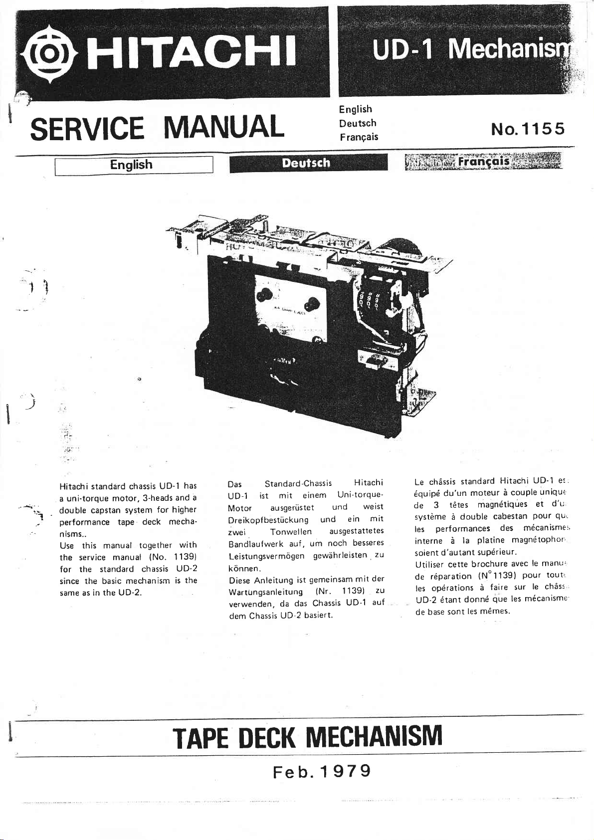
Hitachi
uni-torque
a
double
.
performance
--
nisms..
Use
the service
for
since
same as in the UD-2.
standard chassis
system
tape
3-heads
deck
together
(No.
chassis
motor,
capstan
this manual
manual
the standard
the basic mechanism
UD-'l
for
mecha'
has
and a
higher
with
1139)
UD-2
the
is
Das
UD-1
Motor
DreikopfbestÚckung
zwei
Bandlaufwerk
Leistungsvermógen
kónnen.
Diese
Wartungsanleitung
verwenden,
dem Chassis
Standard-Chassis
mit einem
ist
ausgerÙstet
Tonwel
Anleitung
len
auf,
ist
das Chassis
da
basiert.
UD-2
Hitachi
Uni-torque-
ein
besseres
139)
1
UD-1
weist
und
und
ausgesÎattetes
noch
um
gewahrleisten,
gemeinsam mit
(Nr'
mit
der
auf
et'
chàssis
Le
équipé
de
système à
les
interne
zu
zt)
soient
Utiliser
réparation
de
les
UD-2
de base
standard
du'un
tétes
3
double
perf
ormances
la
à
d'autant
cette
opérations
donné
étant
les mémes.
sonl
Hitachi
moteur
magnétiqúes
cabestan
des mécanisme:,
Platine
suPérieur'
brochure
(No
lI39)
faire
à
que
UD'l
uniqu'.
couple
à
et
Pour
magnétoPhon
le manui
avec
pour
le chàss
sur
mécanisme
les
d'u
qu!
toutt
'
TAPE
DECK
Fe
MECHANISM
I7I
1
b.
Page 2
SPECIFICATIONS,
system
Track
Motor
OUTLINE
ln
cassette
the
ance
the
Multi-pole
OF DEVELOPMENT
decks
are directly
motor
such
items
performance
DC
conventionally
advantages and
Hitachi
with
the
conducted
has
advantages
in developing
motor is
This
is constant;
smooth.
uni-torque motor,
A
players,
addìtion,
circuit,
been
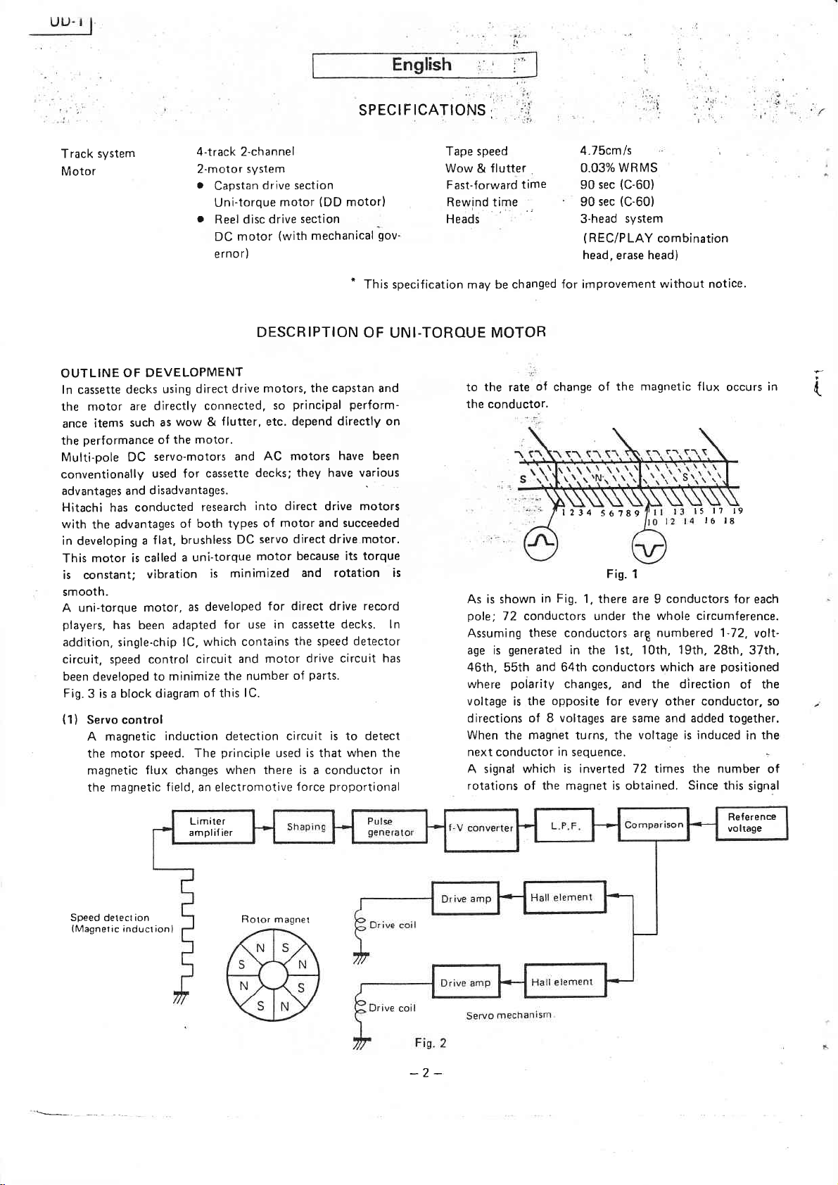
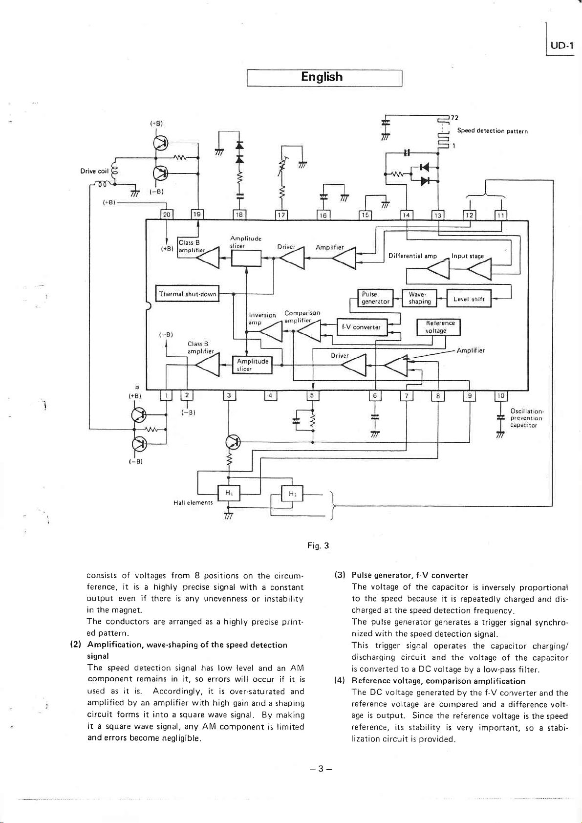
Fig.
(1)
has been adapted
single-chip
speed
developed
block diagram
3 is a
Servo control
A magnetic
motor speed.
the
magnetic
magnetic f ield, an electromotive
the
4-track 2-channel
2-moîor
.
o
system
Capstan
Uni-torque
Reel disc
DC
erno
drive section
motor
r)
drive
DESCRIPTION
direct drive
using
wow &
as
the motor.
of
servo-motors
used for
d isadvantages.
research
of both
flat, brushless
a
a uni-torque
called
vibration
as developed
connected,
cassette
is minimized
motors,
flutter,
etc.
and AC motors
decks;
into direct
types of
servo direct drive motor.
DC
motor
for direct drive
for use in cassette
lC. which
control
cìrcuit
to minimize
induction detection cìrcuit
The
flux changes
contains
and motor
the number
lC.
of this
principle
when there is a conductor in
(DD
motor
section
(with
motor)
mechanical
*
This specif ication
OF UNI-TOROUE MOTOR
capstan
the
principal
so
depend directly on
perform-
have
they
motor and succeeded
because its
have
drive
various
motors
torque
and rotation is
record
decks. ln
the
drive circuit has
parts.
of
used is that
force
detector
speed
is
to detect
when
proportional
gov-
and
been
the
Tape speed
Wow &
Fast-forward
Rewind time
Heads
flutter
time
be changed
may
the
to
the conductor.
rate
of
As is shown
pole;
72 conductors under
Assuming these conductors arg numbered
generated
age is
46th,
where
voltage is the
and 64th
55th
polarity
4.7Scm/s
0.03% wRMs
(C-60)
sec
90
(C-60)
sec
90
3-head
head,
system
(REC/PLAY
erase
combination
head)
for improvement without notice.
change of
l2t4
in Fig.
the magnetic flux
561A9
Fis. 1
1, there are 9 conductors for
the whole circumference.
'lgth.
in the 1st,
conductors
changes, and the direction
opposite
1Oth,
which are
for every other conductor, so
l7 l9
l5
t6
1-72,
28th, 37th,
positioned
directions of 8 voltages are same and added together.
When the magnet
next conductor
A signal which
in
is
rotations of the magnet
turns,
sequence.
inverted
is
the voltage is induced
72 times
obtained.
the
number of
Since this
occurs
t8
of the
in
signal
each
volL-
the
in
(
Speed detect ion
(Magnetic
inductionl
Limiter
amplilier
Bolor magnet
-2-
Reference
vo ltage
Page 3
Drive coil
English
72
Sped
detection
pailern
(-B
Differential
I
Hall elements
amp
-
lnput
stage
consists
ference,
output even if
in the magnet.
The
pattern.
ed
(2)
Amplification, wave-shaping
signal
The
component
used
amplified
circuit forms
it
a square wave
and
errors
voltages
of
it is
highly
a
there is any unevenness
conductors are arranged as a highly
speed detection
remains in
is.
as it
by an
Accordingly,
amplifier
it into a square wave
signal, any AM component
become
from 8
precise
signal
it,
with
negligible.
positions
signal with
the
of
has low
so
errors will
it is
high
on the circum-
a constant
or instabiliîy
precise prlnt-
speed detection
level and
over-saturated and
gain
signal.
an
occur
if it
and a shaping
By making
is llmited
AM
is
Fis.
_?_
3
(3)
Pulse
The
to
charged
The
nized with the
This
discharging
is
converted to a DC
(4)
Reference voltage,
The
reference
age is
reference,
lization circuit
generator,
voltage
the
speed because
at îhe speed deteclion
pulse
trigger
f-V converter
the
of
generator generates
speed
signal
circuit and
DC voltage
output.
generated
voltage are
Since
its
stability is very
provided.
is
capacitor
it is repeatedly
detection
operates the capacitor
voltage by
comparison
compared and
the
is inversely
charged
frequency.
a trigger
signal.
voltage
îhe
by
the f-V converter
reference voltage
of the capacitor
a low-pass f
amplification
a difference
important,
proportional
and
signal
synchro-
charging/
ilter.
and the
is îhe speed
so a
dis-
volt-
stabi-
Page 4
English
(5)
Amplitude slicer
This slices
current
the
amplified
amplifier. When the
speed, the
becomes
element
larger.
When
this operation
(6)
Drive amplification
The Hall
is
amplif ied by
ln
addition.
Since the
WBMS,
installed
it may rise to
incorrectly. Especially,
DD motor
is affected
drive coil.
on the
plate
When re-assembling,
the
damage the
Pay
yoke plate
f
ixing
previously
attention
1) When
flutter
2l
Check
3) Clean
no
oil or dust adheres to
4l
Since
installed
touch it.
output
larger and the width
voltage
speed decreases below the rated speed.
the
element signal sliced
an output
wow
&
incorporated
is
by the
To remove
screws.
marked lines
bearing;
to
the
the oil
the
guard
increases;
the thrust
pressure
the semi-variable
to
the
(limiter)
voltage amplitude
the output of the comparison
from
increases
speed
from
the comparison amplifier
of
amplitude becomes
is reversed.
by
B amplification.
class
transistor outside the lC
flutter
of this unit
more
in the
gap
and
adjust
positioning
and
yoke plate,
the
chassis before loosening
so
(a)
prevent
this value
than
since the drive
yoke plate,
that
the
(b).
and
dust
from
following:
washer touches
gap
it with
set
gap
roller,
of
the flywheel.
of approx. 1mm.
capstan and head, etc.
them.
resistor
plate
yoke
is
for speed
of the Hall
above the rated
the
slice of the
proportionally
the amplitude
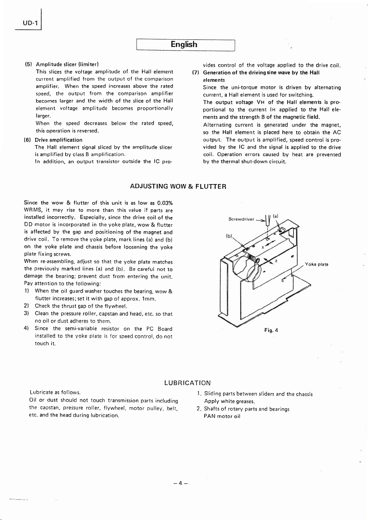
ADJUSTING
is
as low as
if
wow
of îhe magnet
lines
Be
careful not
bearing,
control,
(a)
PC
mark
yoke plate
entering
the
on the
element
slicer
0.03%
parts
coil
of the
flutter
&
and
yoke
the
matches
the unit.
wow
so that
Board
do not
Hall
pro-
are
and
(b)
WOW
to
&
vides control
(7)
Generation of the driving
elements
the voltage applied to the
of
Since the uni-torque
current, a Hall element is used
The
output
portional
ments and
voltage Vx of the Hall
to the current
strength B of
the
Alternating current is
so the Hall element is
output. The output is amplified,
vided by the
Operation errors caused
coil.
by the thermal shut-down
lC
and the
& FLUTTER
síne wave
motor is
driven by alternating
for
lH applied
the
magnetic field.
generated
placed
here
signal is applied
by heat are
circuit.
Fis.
4
drive
by the Hall
switching.
elements
Hall
the
to
under
the
magnet,
to obtain the AC
speed control is
to the drive
prevented
plate
Yoke
is
coil.
pro-
ele-
pro.
Lubricate as follows.
Oil or dust
the
capstan,
etc.
and the
should
pressure
head
during lubrication.
not
touch
roller,
transmission
flywheel,
parts
motor
LUBR ICATION
including
pulley,
belt,
-4-
1
2
Sliding
Apply
Shafts
PAN
parts
white
of rotary
motor
between
greases.
parts
oil
sliders and
and
bearings
the
chassis
Page 5
English
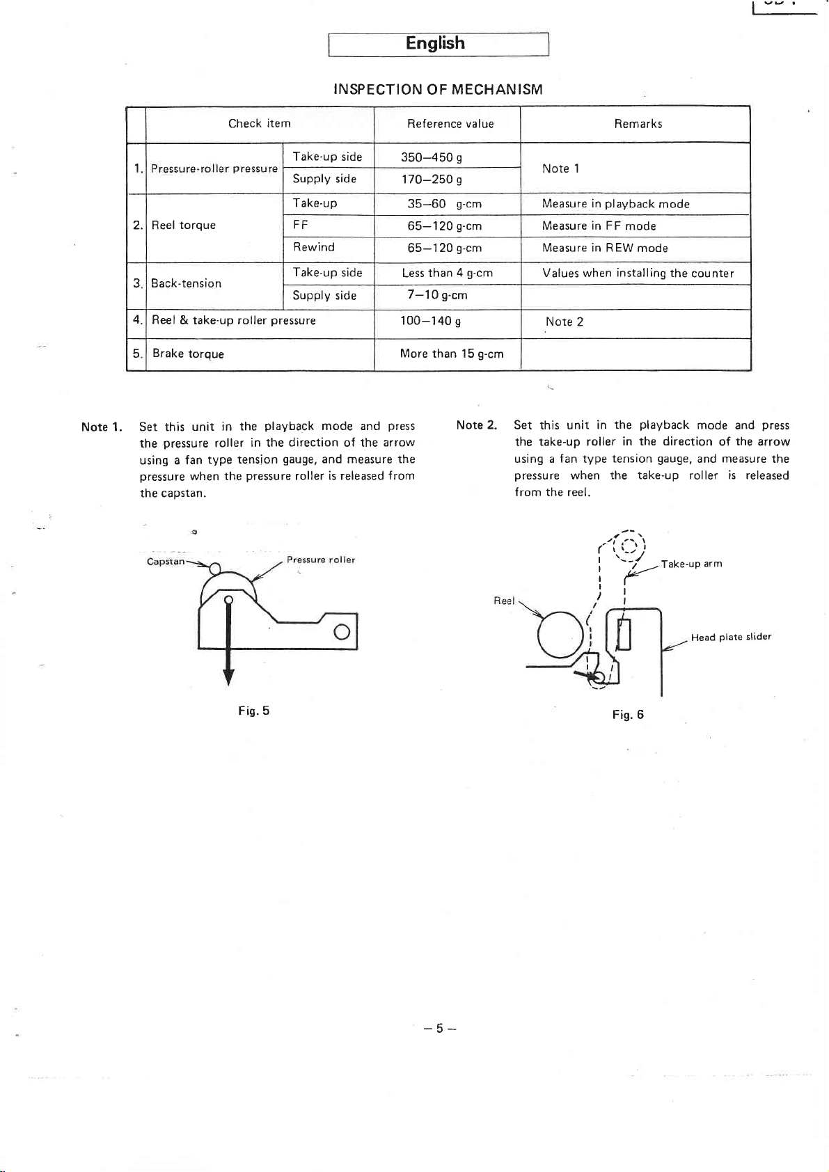
t""'
1. Set this
Note
1
2. Reel
3
4
5
torque
Back-tensio n
Reel
& take-up roller
Brake
pressure
the
using a
pressure
the capstan.
torque
in the
unit
roller
type
fan
when the
Check
P
in the
tension
pressure
item
Take-up side
Supply side
Take-up
FF
Rewind
Take-up
Supply side
pressure
playback
direction
gauge,
roller
INSPECTION
side
mode and
arrow
of the
and
measure
is released f rom
OF MECHAN ISM
Reference value Remarks
l20
than
g-cm
s
than 15
g
g
g-cm
g-cm
g-cm
g-cm
4
g-cm
Note 2.
I
Note
Measure in
Measure in FF
Measure
Values when
Note 2
Set this unit
take-up roller
the
using a fan type
pressure
ìn
in
when
from the reel.
playback
REW mode
350-450
170-250
35-60
65-120
65-
Less
7-10
't00-140
More
press
the
mode
mode
installing
the
in the direction
tension
the
playback
gauge,
counter
mode and
the
of
measure
and
press
arrow
the
the take-up roller is released
Fig.5
(
I
I
I
I
)
'l
'--r/
Fis. 6
r_)
r'
I
)
-r"k"-uo
"r^
Head
plate
slider
-5-
Page 6

Technische Daten
rsyslem
Spu
Motor
Zusammenfassung
ln
Cassetten-Tonbandgeràten
Tonwelle
und
daB wichtige
usw.
direkt
Fúr
konventionelle
sàchlich
selstrom-Motoren
aber
Hitachi
antreibenden
typen
Gleichstrom-Servomotors
unserer
ser Motor
net, da
Lauf
mehrpolige
auch
Nachteile
befaBte
vereint;
Entwicklungsabteilung
wird
er
sich
und minimale
der Entwickl
der
Antriebsmotor
Leistungsdaten
durch
den
Cassetîen-Tonbandgeràte
Gleichstrom-Servomotoren
verwendet,
auszeichnen.
sich
Motors,
mit
der Entwicklung
von uns
durch
ein konstantes
Vibrationen
Antriebsmotor beeinfluB
mit der Entwicklung
der
Dieser Uni-torque-Motor
spieler
Motor
Tonbandgeràten
Bauteile
hat
entwickelt,
Regelung
mit
Direktantrieb
dieses
auf ein
Hitachi
und
Prinzips
auch
der
die Motor-Treiberstufe
kommt
zur
Anwendung.
absolutes
einen
den
iertelspur-Stereo
V
ren-B
2-M oto
r
irektantreibender Uni-tor-
D
que-Motor
o
Gleichstrom-Motor
and laufwerk
chanischem
fùr
Wickeltel
ungsgrundsàtze
mit
Direktantrieb
direkt
wie Gleichlaufschwankungen
die
sich durch
Vorteile
die
(40
"Uni-torque-Motor',
mit
wurde
entwickelt;
nun
dieser
eines kollektorlosen
Patente
Erfolg
auszeichnet.
ursprùnglich
jedoch
angemeldet)
beschieden.
Drehmoment,
ein
noch
auch
Um
Minimum
integrierten
Drehzahl-Detektor,
begreózen
Ein-Chip-Schaltkreis
enthàlt.
fùr
Tonwellen
mit
Drehzahlregler
lerantrieb
Beschreibung
sind
verbunden,
werden.
werden
bestimmte
beiden
die
die
haupt_
oder
Wech-
eines
direkt_
Motor-
bezeich-
ruhigen
platten.
fúr
verfeinerter
in
Cassetten-
Anzahl
zu
kònnen,
Drehzahl-
Vor-
war
Die_
der
me-
die
so
Bandgeschwind
G leichlauf
Sch nellvorlauf
R
iick lauf
Kopfbestúckung
*
Anderungen
des
U n i-torque-Motors
ln Abb. 3 ist das Blockschaltbild dieses
kreises
(1
Servo-Regelung
)
Ein
spiirt die Motor-Drehzahl
in einem Magnetfeld
motorische
portional
Wie
Pol
Leiter am
finden.
72
37., 46., 55.
igkeit
schwankungen
zeit
zeit
im
Sinne
dargestellt.
magnetischer
Kraft in dem
zur Anderung
der Abb.
aus
9 Leitern
Umfang
Werden
bezitfert,
4,75
cm/sek.
o,o3%
90
90 sek.
3
Wiedergabekopf
hàuse,
stàndiger Verbesserungen
lnduktions-Detekîorschaltkreis
(Mittelwert,
(Cassette
sek.
(Cassette
Tonkópfe
Lóschkopf)
auf. Dabei wird
bewegt,
Leiter
der Magnetf
1234
56789
I entnommen
gebildet,
in
diese
dann
wird
und
64. Leiter,
gleichmàBigen
Leiter
l2
werden
so daB
mit
jeweils
an welchen
bewerter)
C-60)
C-60)
(Aufprech-
in
einem
vorbehalten.
inregrierten
Schalt-
ein
so daR eine
erzeugt wird, die
luRdichte ist.
l3 ls l?
l4 r6
kann,
sich
den
im
1.. 10., 19..
elektro-
l8
wird
insgesamt
Abstànden
Zahlen
die Polaritat
und
Ge-
Leiter
pro-
jeder
72
be-
1
bis
28.,
Drehza
h ldete
(magnetische
kto r
lnduktion
Treiber-
2
Verslàrker
r-
Treibe
Verstar
k er
)
Abb.
-6-
Page 7

Vcrrtarkcrd.,
B.r.,.br!tÀre
Betrrebrkls)1
-
Amplirud€negranzer
Hf_l
rrcl'oe:/4
verrràrker
wechselt, eine Spannung
jedem
in
tung
ist
weiterdreht,
darauffo
Dadurch
drehung
besteht aus den addierten Spannungen
Umf ang
anderen
der
gleich
lgenden
wird ein
des Magnets
gleichméBig
Spannung in
und wird addiert. Sobald der Magnet
wird
Leitern induziert.
Signal
einen konstanten
Magnet
einer
(21
Verstàrkung
Detektorsignals
nicht stabil
pràzisen. gedruckîen
und Wellenform-Bildung
induziert; die Spannung isî
anders
Leiter
den acht
eine Spannung
erhalten, das
umgepolt
verteilten
Pegel aufweist, auch wenn der
sein sollte. D
Leiterplatte untergebracht.
Das Drehzahl-Detektorsignal
gerichtet.
genannten
Die Rich-
in den
72-mal
pro
wird. Dieses
von acht
Leiîern, so daB es
ie
Leiter
sind
Drehzahl-
des
weist niedrigen
Leiter
jeweils
Um-
Signal
am
auf
Pegel
Abb. 3
-7 -
auf
Fehlern kommen kónnte,
veràndert verwendet wird.
dieses
Verstàrker
Wellenformer
geformt.
lensignal werden alle AM-Komponenten begrenzt,
daB
Pegel
(3)
lmpulsgenerator; Frequenz/Spannungs-Wandler.
Die
portional
enthàlt
und
AM-Komponenten,
wenn
Aus diesem Grund wird
in
Signal
auftretende
reduziert werden.
Spannung
einem
hohen
Gewinns verstàrkt und
in ein
die Umformung in
Durch
Fehler
des
Kondensators
iibersàttigten Zustand
Bechteckwellensignal
einen
auf
zur Drehzahl, da der Kondensator
daB
so
dieses
Signal un-
ein Rechteckwel-
vernachlàssigbaren
ist umgekehrt
der Drehzahl-Detektorfrequenz wiederholt aufgeladen
bzw. entladen wird.
lmpulsgenerator
Der
erzeugt
ein
Trigger-Signal, das
es
zu
in einem
in einen
um-
pro-
gemaB
mit
so
Page 8

dem Signal des
Dieses Trigger-Signal dient
densator-Lade-
nung
des Kondensators
ters
in eine Gleichspannung
(4)
Bezugsspannung
vom Frequenz/Spannungs-Wandler
Die
spannung
so daB
Bezugsspannung
ein
daB
Stabilisationsschaltkreis
(sl
Amplitudenbegrenzer
stabiler
Drehzahl-Detektors
und
Vergleichsverstàrkung
;
und
die
ggf.
eine Spannungsdifferenz
dient als Drehzahl-Bezugssignal, so
Pegel
Der Amplitudenbegrenzer
der
Spannungsamplitude,
fert wird und
des Hall-Elementes
Signal
zahl die
Ausgang
Bandbreite
Hall-Elementes
Drehzahl
wird der eben
das im
Nenndrehzahl
des Vergleichverstàrkers,
der begrenzten
proporrional
dagegen
genannte
synchronisierî
zur Steuerung
-Entlade-Schaltkreises;
wird mit Hilfe eines
umgewandelt.
erzeugte Gleich-
Bezugsspannung
werden
anfàllt. Die
erforderlich
erhalten
sorgt
die
Vergleichsverstarker verstàrkîe
darstellt. Sobald
Ùberschreitet,
ist, der durch
wird.
fùr eine
vom Hall-Element
erhóht sich der
so daR auch die
Spannungsamplitude
wird.
sinngemàB
unter
Vorgang
erhóht
Nenndrehzahl
die
ist.
des
Kon-
die
Span-
TiefpaRf il.
verglichen,
einen
Begrenzung
gelie-
die Dreh'
des
Fàllt
die
ab, dann
umgekehrt.
(61
Trei be
rverstérke
Das durch den Amplitudenbegrenzer begrenzte
des Hall.Elementes
Betriebsklasse B
auBerhalb des
brachter
angelegte
(7)
Erzeugung
Da
der Uni-torque-Motor
trieben
wird, wird
verwendet.
Elementes ist
eingespeisten
(B).
stàrke
Der Wechselstrom
das Hall-Element in diesem
ist,
um ein Wechselstrom-Ausgangssignal
Dieses Ausgangssignal wird
Drehzahlregelung
Ausgangssignal
das
Eine thermische
von
Temperaturànderungen
r
wird
in einem
verstàrkt.
integrierten
Ausgangsîransistor
Spannung.
einer
Treiber-Sinuswelle im Hall-Element
Zusàtzlich steuert ein
Schaltkreises
an
die
durch Wechselstrom ange-
Hall-Element
ein
Die Ausgangsspannung
proportional
Stromstàrke lx und der Magnetleld-
entsteht durch
zu der dem Hall-Element
den Magnet. so daR
Schaltkreis
verstàrkt, die
wird mittels lC
durchgefùhrt und
wird an die Treiberspule
Schutzschaltung unterbindet aufgrund
auftretende Fehler.
Signal
Verstàrker
(lCì
Treiberspule
die
der
ange-
zum Umschalten
Hall-
des
Vx
angeordnet
zu erhalten.
Motor-
angelegt.
Abgreich
Die Gleichlaufschwankungen
nur 0,03%
tert
werden. Die
ist
schwankungen durch den Abstand zwischen und die
sition des Magnetes und der Treiberspule
Wenn die Jochplatte
und
bevor
werden. Beim
einzubauen, daB die angebrachten
(b)
genau
das
Geràt eindringt.
(Mittelwert,
werden, wenn die
Treiberspule des direktantreibenden Motors
in die Jochplatte
ausgebaut
(b)
an der Jochplatte und
die Befestigungsschrauben
Zusammenbau ist die Jochplatre danach
ùbereinstimmen.
nicht beschàdigt wird und
Lager
Besonders die
1) Die Ólschutzscheibe
dieses Laufwerkes
bewertetl.
kònnen
Teile nicht
eingebaut, so daB die
wird,
die
am Chassis anbringen,
der
Markierungen
Unbedingt darauf achten, daB
kein
folgenden Punkte beachten:
in einem Abstand
fùr minimale
betragen
aber verschlech-
richtig
Markierungen
eingebaut
leichlauf-
G
beeinfluBt
Jochplatte
(a)
Staub in das
von
etwa 1 mm
gelòst
vom Lager einbauen. da die Gleichlaufschwankungen
erhóht werden, wenn die
2l
3)
4l
Axialspiel des
Das
Andruckrolle, Tonwelle,
vreder
damit
Der auf der
angebrachte Regelwiderstand dient
regelung
und
noch
Ól
Leiterplatte
darf daher nicht berÙhrt
Scheibe
Schwungrades
Staub
(montierî
das Lager berùhrt.
ùberprúfen.
Tonkópfe
an diesen Teìlen
usw. reinigen,
auf der
fúr die Drehzahl-
werden.
anhaftet.
Jochplatte)
Po-
wird.
(a)
und
Gleichlaufschwankungen
so
Schraubenzieher
>f[
Abb.4
Joch
p
I
atte
-8-
Page 9

UD.1
Hinweis
And ruk
2 Wicke
Rúckhaltemoment
3
Druck
4
wicke lte
Auf
Bremsmoment
5
1:
Dieses
Andruckrolle
(oder
tung
messen,
welle abzuheben.
rollen-Druck
rehmoment
ler-D
ltel
Wickelteller
am
llerro
auf
Geràt
mit
Spannungsmessers)
eines
um
danach
die
ziehen;
nkte
rijfpu
P
an der
und
lle
Wiedergabe
einer Federwaage
Hilfe
die erforderlíche
Andruckrolle
Prrifung
Aufwickelteller
Abwickelteller
Aufwickelteller
Schnellvorlauf
Rùcklauf
Aufwicke lteller
Abw ickelteller
in
von
und
Pfeilrich-
der Ton'
schalten
des Laufwerkes
die
Kraft
Bezugswerte
350-450
17O-25O
65-60
65-120
60-120
weniger
7-10
100-140
mehr als
Hinweis 2:
g
s
g.cm
g.cm
g.cm
g.cm
als 4
g.cm
s
g.cm
15
Dieses Geràt
Aufwickelrolle
(oder
eines Spannungsmessers)
ziehen;
tung
messen,
teller abzuheben.
B emerkungen
Hinweis
Bei
Bei
Bei
Bei
Hinweis 2
um
1
Wiedergabe messen
Schnellvorlauf
Búcklauf
eingebauten
auf Wiedergabe schalten
danach die
die
messen
Zàhlwerk
Hilfe
mit
erforderliche Kraft
Aufwickelrolle
messen
einer
die
und
Federwaage
Pfeilrich-
in
vom Wickel'
Tonwelle
Die Schmierung
und Staub
Ol
(Tonwelle,
scheibe,
Andruckrolle,
Antriebsriemen
ist wie
dtirfen
Abb. 5
nachfolgend
jedoch
nicht
Schwungrad,
usw.)
oder
gezeigt
an den
am
Tonkopf
Schmierung
vorzunehmen'
Laufwerksteilen
Motor-Riemen-
anhaften.
W ickeltel
I
Gleitf
t rage
Wellen von
2.
ler
liichen
n.
zwischen
drehenden
,'(-i;
a
'-J
i,-
Abb.6
Gleitstùck
Teilen:
Auf wickelarm
K
o
und Chassis:
Motoról
pfrràger-G
PAN
leitstùck
Fett
auf-
-9-
Page 10

Fiche technique
Système de
pistes:
Moteur:
les
pleurage
le
póles
générale
platines
direct.
de sorte
performances
multiples et les moteurs C.A. équipent
platines
inconvénients.
Description
Dans
entralnement
ment reliés
que
ment des
C.C. à
lement les
comme des
Hitachi a établi un
entrainement direct
modèles
C.C.
porte
couple
maximum et
au
moteur
Un
traînement
adopté
ulîra-mince
un
circuit de contròle
moteur et
de
sans
balais,
le nom de moteur
est constant
à couple
direct
pour
les magnétocassettes. Par
renfermant
l'amélioration
de
à cassettes
le cabestan
que
scintillement.
et le
à cassettes et
plan
possédant
a
plat
et
parce
unique a été mis au
d'une
de
du moteur a également
au maximum
les
composants
pistes,
4
Système à 2 moteurs
.
.
2 canaux
Section
cabestan Moteur
(moteur
Section
teau
(muni
que)
d'entrainement
DDI
d'entrainement de
bobine
de
d'un régulateur mécani-
'
Ces renseignements
à couple unique
Moteur
Description
employant des
et le moteur
performances principales
les
sont
etc, dépendent
du moteur. Les
présentenî
recherche
de
servomoteurs
des
sur les
les avantages
réussi
à construire un
entrainement direct.
à
couple
servomoteur
Ce moteur
unique
et lqs vibrations sont
rotation
sa
platine
un circuit de détection
vitesse
été mis au
internes.
est très régulière.
point pour
tourne-disques
ailleurs, un seul Cl
circuit
et un
point pour
de commande
de
C.C.
techniques
moteurs
directe-
telles
directe-
habituel-
avantages
moteurs
des deux
parce
réduites
l'en-
et a été
vitesse.
de
limiter
pla-
peuvent
du moteur à
à
à
son
Vitesse
Pleurage
ment:
Durée
Durée
Tètes
de
défilement:
et scintille-
d'avance
de rebobinage:
magnétiques:
changer sans
rapide:
préavis
4,75
cm/sec.
0,037"\^/RMS
90
sec.
90
sec.
Système
comb inée
une
tète
pour
des raisons
couple unique
figure 3 représente
La
circuit
intégré.
(1)
Servocommande
Un circuit de détection
la
te
vitesse
térise
produit quand
se
magnétique, une force électromotrice
au îaux
dans le conducteur.
du
par
le fait
variation du flux
de
le
moteur. Le
qu'un
changement
il existe
56149
1234
Figure 1
diagramme synoptique de ce
induction
à
un conducteur dans
(C-60)
(C-60)
à
3 tétes
enregistrement-lecture,
d'effacement)
magnétique détec-
principe
du
magnétique
l3 t5 I
l4
l2
(une
.
d'amélioration.
utilisé
se
flux magnétique
le champ
proportionnelle
se
l6
téte
carac-
produit
Déîeclion
(
inducation
vitesse
de
magnétique)
Aimant du
Formaîion
d'onde
rotor
Générateur
d'impulsions
Bobine
commande
de
Bobine
commande
Figure
-
de
Tension
nce
référe
nt à effet
de
10
Elément
de Hall
Servo-mécanisme
2
-
à ef
fet
Page 11

UD-1
Eobine
de
cohmande
Ampr,lrcateur
deClsreB I
:i1''.":
Omptrtuoe
Ampli
d inverlion
-
de commande
Ampliltcaieur
comPararlon
de
72
Seclron
de la vrîer3e
de
délection
Comme
chaque
que
générée par
37ième,
qui
sens
indiqué
pò|e,72
les conducteurs
le
placés
sont
tension est opposée
la
de
teurs, le sens
le
46ième, le 55ième
la figure 1,
sur
conducteurs
premier,
aux endroits où
des 8 tensions
I'aimant tourne. une
suivant
et
dans
I'ordre.
Un signal inversé 72
est ainsi
tensions
obtenu.
produites
Etant
par
moteur, il est très
particulièrement
une
ou
instabilité
constante
au niveau
il existe
périphérie.
à la
numérotés
sont
le 1Oième,
le 19ième, le 28ième, le
et le 64ième
polarité
la
pour
tous les autres conduc'
est le méme et s'ajoute.
tension est
fois le nombre de
donné
les
précis
induite dans le conducteur
que
ce signal
positions
8
la sortie
et
méme s'il
de l'aimant.
9
conducteurs
En
supposant
1
72,
de
à
tension
la
conducteur
change et
que
Ouand
rotation de l'aimant
se compose des
périphérie
à la
obtenue est
une irrégularité
existe
pour
Figure 3
le
du
-
Les conducteurs
motif
(2)
Amplification
tion
Le
un composant
erreur
il subit
ensuite
qu'un
onde
carrée,
est
(31
Générateur
tensi
La
11-
sonî disposés
imprimé.
et formation
vitesse:
de la
de détection
signal
en fait
AM
produit,
se
une
amplifié
circuit
carrée.
tout
alors negligeable.
est utilisé tel
il
une saturation
subit
par
l'amplificateur
formation
de
En le transformant
composant
d'impulsions,
on.
tension du condensateur
un ordre
dans
d'onde
de vitesse
partie
de sorte
quel.
le transforme
évité et
est
AM
Convertisseur
inversement
est
précis
sur
signal de
du
bas niveau
est à
que
conséquent,
Par
pour
excès
en
gain
élevé tandis
à
en signal
en signal à onde
le taux d'erreur
fréquence'
propor'
détec-
une
si
étre
un
et
à
Page 12

tionnelle à la vitesse
chargée
détection de
Le
clenchement
v i tesse.
Ce
charge et
du condensateur
par
(4)
Tension de référence,
en cycle répété en
la vitesse.
générateur
signal de
un filtre
d'impulsions
synchronisé
declenchement
de
décharge du condensateur et
passe-bas.
est convertie
La tension continue
fréquence-tension et la tension
parées pour
Etant
la vitesse
et c'est
ment
(5t
Ecréteu
Cet
tension
plifié
Quand la
nale, la sortie
mente
tension de
mème
écréteur a
qu'une
donné
de
pourquoi
prévu.
r
tension différentielle soit
que
la
tension de référence correspond
référence,
un circuit de
pour
du courant de l'élément à
par
la
sortie
de
vitesse
et
proportion.
augmente et dépasse la
de
l'amplificateur de comparaison
largeur
la
élément
à eff et de Hall
Ouand la vitesse
parce qu'elle
rapport à
au
est
chargée et dé-
la
produit
signal
commande le
un signal
de
détection
fréquence
circuit
la tension
en tension
amplification de comparaison
produite par
sa stabilité
rÒle
de couper l'amplitude
le
référence
de
est
stabilisation
effet
l'amplificateur
de la
coupure de I'amplitude
de comparaison.
augmente
diminue
continue
convertisseur
sont
obtenue.
importante
très
est égale-
de Hall
vitesse
et tombe
de
de dé-
de la
de
com-
de
am-
nomi-
aug-
de
dans la
en-dessous de
produit.
se
(6)
Amplification de
Le signal
l'écréîeur
B.
Par
ailleurs,
fournit une
bobine
(7)
Génération d'une
les
Etant
mandé
de
à
faite.
de
quée
sorte
sorte
assuré
commande.
d'une
de commande.
éléments
donné
par
Hall
La tension
Hall est
aux
(B)
du champ
Le courant
que
qu'une
La sortìe est
par
formation de
l'emploi d'un
la vitesse nominale,
commande
coupé
de
est amplifié
transistor
un
commande
onde
à effet de
que
le moteur à couple unique esî com-
un courant
employé
est
de
proportionnelle
éléments
à
magnétique.
alternatif
sortie
à effet de
à courant
l'élément
amplifiée,
le signal est appliqué
et
le Cl
Les erreurs
chaleur
de coupure thermique.
circuit
l'élément
par
une
de sortie indépendant
de
sinusoidale
Hall.
alternatif.
que
pour
sortie
VH
effet de Hall et à
produit
est
le contròle
de fonctíonnement
l'opération
à effet de
amplification
inverse
Hall
de classe
la tension appliquée
de commande
un élément à
la commutation
des éléments à effet
la
l'aimant de
placé
soit
la vitesse
de
à la bobine
évitées
lx appli-
puissance
de
obtenue'
par
gràce
l'intensité
à
Hall
alîernatif
ainsi
sont
sous
est
par
du Úl
à la
par
effet
soit
telle
est
de
suite
à
Etant
donné
appareil
risque
d'augmenter
lés. Ceci
de
commande
de carcasse,
affecté
bine
de
porîer
avant
de desserrer
Au moment
de carcasse
(b).
Faire
des saletés ou
Faire
très
1)
Ouand
le
l'écartement à environ 1mm.
2l Vérif ier
3)
Neîtoyer le
autres,
lent
que
le
est si bas
qu'il
si certains composants sont
s'applique
particulièrement
du moteur
pleuràge
le
par
l'entrefer et
commande.
des
repères
avec les
(a)
les vis de fixation du
remontage, ajuster
du
attention au
poussière
de la
attention sux
la rondelle
pleurage
dessus.
et
l'écartement de butée du
galet-presseur,
pour
éviter
Réglage
pleurage
et
la
Pour retirer le
et
repères
points
de retenue d'huile touche
le
et le scintillement de
ne
dépasse
DD est ìncorporée
le
scìntillement
position
(b)
portés
palier
de
suivants:
scintillement
que
l'huile
pas
au
l'aimant
de
plateau
plateau
le
sur
plateau.
posltron
la
avant le démontage
de l'appareil et empècher
rentrer à l'intérieur.
volant.
le
cabestan, les
et
0,03?6WRMS, il
fait
augmente,
la
pleurage
du
cet
mal
instal-
que
la bobine
plateau
le
dans
est directement
la
et de
bo-
de carcasse,
le
et
chàssis
plateau
du
(a)
palier,
le
régler
tétes et
poussière
col-
et du scintillement
4l Etant
donné
plaquette
à circuits
de carcasse est
prendre
pas
la
toucher.
toutes les
que
la
imprimés
destinée à
précautions
Figure
demi-résistance
montée
la
régulation
nécessaires
Plateau de carcasse
4
variable
sur le
de
pour
de,la
plateau
vitesse,
ne
-12-
Page 13

lnspection du mécanisme
'|
2.
3 Tension
4.
5. Couple
Remarque
Elément
galet-presseur
Pression
Couple
Pression de
d'enrou lement
de
de bobine
arrière
de freinage
1l Cet
galet de débit et
appareil
lecture
indiqué
sens
dynamomètre
presséur
controler
à
doit
presser
puis
par
est séParé
E n rou leme
Débit
En rou
FF
Rebobinage
rou lement
E n
nt
leuse
Débit 7-'l 0
étre réglé
galet-presseur dans
le
feèche
la
pression
la
cabestan.
du
en mode
utilisant
en
quand
le
Valeur
350-450
170-250
35-60
65-120
65-'l
moins
1 00-1
mieux
de
le
un
galet'
de référence
sr
sr
gr-cm Mesurer
gr-cm Mesurer
gr-cm
20
gr-cm
de 4
gr-cm
gr
40
que
gr-cm
15
Remarque
Remarque
Mesurer
Valeur
compteu r.
Remarque 2
Régler
2:
presser
indiqué
et mesure
d'enroulement
Remarques
1
cours du
au
cours
au
cours
au
moment
au
l'appareil
le
par
mode
mode
du
du mode
de l'installation
en
galet
d'enroulement
la f lèche avec
pression
la
séparé
est
de lecture
FF
REW
mode
un
quand le
de
du
lecture
de
dans le sens
dynamomètre
bobine.
la
et
galeÎ
Cabestan
graissage est spécifié
Le
pas
Ne
contact
cabestan,
courroie,
mettre
les éléments
avec
galet-presseur,
le
et les
etc.
d'huile
ci-après.
permettre
ou
au
tétes
5
Figure
des saletés
à
de transmission
poulie
graissage.
du
la
volant,
le
cours
venir en
de
comprenant
moteur,
G rai
le
la
ssa
ge
1'
2'
Bobine
Parties
Mettre
des
Axes
Mettre
coulissantes
graisse blanche
la
de
pièces
rotatives
l'huile
de
entre
moteur
'i
Figure
les
rou
et
PAN
í-ì ì
\-':./
/'--
(
6
coulisseurs
lements.
d'enroulement
Bras
et le
chàssis'
-
13
-
Page 14

REPLACEMENT
PARTS
LIST Ersatztelliste
Liste
de
pièces
de
rechange
sYnSuL-t!0
I
2
t
,
ó
7
I
I
l0
'
'
'
ll
72
l,
l4
t5
l6
T7
lÉr
l9
20
2l
22
,
?'
?4
?,
26
?7
28
!0
t2
l3
!4
,5
ló
57
l8
.19
40
4t
42
4t
45
4ó
P-No
F0R CTSSEIIE
7r00ó92
4
5
44
òó.r
778l7tl
6t2t24'
54451ól
728124)
8781r44
ó752081
ò5{5121
6t8!281
ót83!15
7 I
A62t5
778ó?16
61047
2L
ó10657I
ó1085ó,
0948275
750011?
718e545
ó4I30r2
ó!08552
778IIt2
64L275t
7100124
ó58ó001
ó100981
7l00tJ4
754)t
24
ò102062
75tóul?
710ò515
ó75r013
rr
5
ó
2l94
5642aA2
TrlI5ql
5ót
!092
1
57 5542
657
627
|
5r7 ?7 9l
ó57ó
084
751c002
ò1049(1
ór729ll
778ó625
7186219
alzr
m
pt
LTESCF
I
0ECK ASS€ftBLY
HEAO
PLAIE
ASSEXELY
RECORD
PLAYEACX
SPECIAL
HEAD
ERASE HE^D
ERASÉ HEAO
IIN0
HEAD
5PR I
PRESSURE
PRESSURE
POLYSL
POLY5L
ADJUST
SPRING
SPR
BALL
EALL
LOCKJNG IASHER
TAKE
5PR I hG
sCREr
SPR
NG
I
SPAC€R
SCREH-2.óhH0Xl(nx
EASE
NG
ROLLER
ROLLER AFI'
DIR HASHER
I
OER
IJASHER
I
5PR
NG
I
NG
I
PRESS
UP
ARII ASS€XBLY
BI SCR€I
fURNI^BLE
SRAKE PIAIE
ERAKE RUBBER
SPR
FR
L€VÈIT SHAFT
SPR
LOCK
PLAY
SOLENOID
s0LtN0l D asstà8LY
SOLENOID
RÉLAY
FTETJ
fU'dE
RELAY
ra0f0R
RU88ER
SCREi
SPR
FLYHHEÉL
POLY SLIOER
POLYESTER
FLyrrHE€L
NG
I
LEVER
N6
I
LIVER PIN
LEVER
HOLOEIi
RELAY.
CAP
A55E11ELY
PLÀTE
FOR hOTOR
NG
I
HOLDER
LEVÉR
ASSEIIBLY
ASSE(BLY
II^SHER
gASHER
,rr-r
loti
(A'
XEAD
ARII
ASSÉhBLY
ASSEHBLY
ASSEÍ8LY
I{OUNTIIG
(L)
q5&80g2_
SY},I8OL.NO P-NO
4't
+;r+#t
{8 7I09ó5!
49
1776A32 POLYESIER
50
Oó!8'ó{
5l
6ó21óOl
,
52
ó!54t61
5!
7!079{?
54 6!OIOII
55
7'OI08' H€AO
5ó 6l()l16t
51 7l0ló04
58
754{021
59
6'02821
ó0
ó7.85ó4
ól
751!424
62
ó!0898!
ó!
67'20L2
64
óto2BlI
ó5
óogl72l
óó
ó!os9!2
67
ó7{880t
ó8
6tO26O2
ó9
5ó0lt2l I'tlcRo
70 729050
7t tót!]ór
12 77ó!8ll
7t
ó750021
7..
ót0257ó
75 6723643
ót720ól
76
77ó189t
17
78 5e70871
DESCRIPIION
FR
BEL1
FAGNET ASSE}IBLY
XOIOR PULLEY
CoUXTER
SENS
t.rG 8€Lf
REC
SLTDER
LOCK LEVER
PLAIE
SPRING
EJECT
LEvEfì
LEVER sH^FT
sPRII.'G FOR
ARX
LoCx
LEVER SHAFT
SPRIN6
CASSETTE
spRtNG
c^ssEtfE
spRlNG
oAxPER ARt{
SPRIXG
FOR
SHlTcH
G0VERNoR
I
sHlfCH
PUSH
lNSuLATtr,tc
EJECTER ASS8XELY
EJECTER
FLYIiHEEL
R0Î0R ASSE|IELY
INSUL
C0l
TING Sl{EEt
P.t.g
L
5PR
4é88OZ3Z
HASHER
HOLOING
PULLEY
SPRING
REIURN
LEVTR
EJECT
LEVER
HOLDER
ARH
TRAy AssEÉBLy
ASSEXELY
ARX
0ALPER
FTBER
XG
I
SUPPORI
assEHÈLY
SCREI
-14-
Page 15

EXPLODED
VIEW
Auseinandergezogene
Darstel
lung
Vue
éclatée
(j
P3X5
.a'
t:l
oo
-a1-
--.:7
-\
22
F3X6
20
'j
(t
'\
@
76
30
-
15
-
Page 16

Vue
éclatée
ff83x6
83x
H
+
(
N>
B3X8
74
58
59
\-
h'
'ta
'l-
o@t^
.t0
(
50,
l
I
\ì
47
)55r\
:,13
i
l'
I
l*
f\
\
Note:
components
Die
ohne
pièces
Les
marked
Nummer
sans
numéros
withouî
in dieser
indiquées
numbers
Zeichnung
sur
in
this
drawing
angegebenen
le
schéma
are
not
sind
specified
keine
Tiele
ne correspondent pas
repracement
as
spezifizierten
pièces
à des
parts.
Ersatzteile.
de rechange.
-16-
 Loading...