

Page 1

INSTRUCTION MANUAL
FOR
MODEL TM3030Plus
TABLETOP MICROSCOPE
(USER’S OPERATION/MAINTENANCE EDITION)
・Before using the instrument , read the safety instructions and
precautions carefully.
・Be sure to follow the instructions and warning of instruction manual
and warning label.
・Keep this manual in a safe place nearby so it can be refer red to
whenever needed.
Copyright C Hitachi High-Technologies Corporation 2014. May/2016 5th Edition
All rights reserved. Printed in Japan. Part No. 55E-8881-4 HR-G (HMS)
Page 2

NOTICE:
1. Infor m at ion contained in this document is subject to
change without notice for improvement.
2. This manual is copyright ed by Hitachi High-Technologies
Corporation with all rights reserved.
No part of this manual may be reproduced, t ransmitted or
disclosed to a third party in any form or by any means
without the express written permission of Hitachi
High-Technologies Corporat ion.
3. Hitachi High-Technologies Corporation assumes no
liability for any direct, indirect, or consequential damages
arising from use not described in this manual.
Utmost care must be exercised when using the
instrument.
4. This document does not provide any warranty or
permission for industrial propert ies or any rig ht s t o grant
license lawfully and without infringement.
Page 3

PREFACE
Thank you for your recent purchase of a TM3030Plus Tabletop Microscope.
The TM3030Plus Tabletop Microscope (“TM” for short) is designed to observe microstructure
of specimen surface prepared specifically for the TM, using an electron beam accelerated to
5 or 15kV as a light source.
This product involves the use of a vacuum and high voltages. In order to ensure the safe and
proper operation of the system, you are urged to receive a briefing on operation,
maintenance, and safety precautions by representatives of Hitachi’s service department or
technicians certified by the same. Carefully read the safety tips provided in this manual, and
use the system after you have thoroughly understood the safety precautions (“Safety Tips”
for short) contained in this publication. After reading this manual, keep it in a safe place for
future referen c e .
When allowing children and pupils (“minors”) to use the system, do so under the
supervision of a system administrator who is thoroughly familiar with the
above-mentioned safety tips, and by limiting their use to personal computer (PC)
operations and moving the specimen stage. Because minors can take unexpected
action out of curiosity, the system administrator should use utmost caution not to
operate the system miners independently or unmentioned way (in this manual).
ABOUT THIS INSTRUCTION MANUAL
This Instruction Manual describes TM operating methods, maintenance and inspection
methods, items that are necessary to support these requirements, and items that require
special attention.
The Instruction Manual consists of the following components:
Cautionary Items (warranty, installation, relocation, after service, the life length of the
system, and other items)
Safety (a summary of safety tips)
Chapter 1: SPECIFICATIONS AND INSTALLATION CONDITIONS (installation
conditions, customer-provided items, and so forth)
Chapter 2: INSTALLATION AND SETUP (installing an application, connecting the
system to the PC, and so forth)
Chapter 3: SYSTEM CONFIGURATION (configuration, descriptions of parts, and so
forth)
Chapter 4: OPERATIONS (image observation, saving image data, and so forth)
Chapter 5: MAINTENANCE (beam axis adjustment, servicing the various parts, taking
corrective action, and so forth)
Chapter 6: REPLACEMENT PARTS (consumables, finite-life items, and lists of spare
parts)
Chapter 7: 3D-VIEW (Option)
APPENDIX
- 1 -
Page 4

First, please read the sections on “IMPORTANT” and “For the Safe Handling of the
System” provided at the beginning of this Instruction Manual.
List of Abbreviations
Abbreviations that appear frequently in this Instruction Manual and their full spellings are
given below:
PC: Personal Computer
HV: High Voltage
DFP: Diaphragm Pump
TMP: Turbo Molecular Pump
FOV: Field of View
- 2 -
Page 5

IMPORTANT
Product Warranty
Product Warranty
Hitachi High Technologies Corporation (“HHT”) warrants that the Model TM3030Plus Tabletop
Microscope is free of defect, either in material or manufacturing, based on the specifications
provided in this Instruction Manual, provided that the system is used in compliance with the
contents of the Instruction Manual.
If your product fails during the warranty period due to a manufacturing defect, it will be
repaired free of charge at HHT’s discretion. In the event of a repair, substitute parts may be
used or your system may be replaced with an equivalent product instead of repairing it. For
example, in the case of PCs, printers, and the like that are used in conjunction with the
system and that are frequently discontinued and replaced with newer models, it may not be
possible to provide the same model as the one that is needed to be replaced. The warranty
does not cover systems that have been discarded, systems that have been relocated without
notice to HHT, systems that are purchased from a reseller, and consumables or parts with a
limited warranty period that have failed after the warranty period.
Geographic Area of Warranty
The warranty is limited to within the borders of the country in which the product was
purchased.
Warranty Period
The warranty period is one (1) year from the completion date of installation.
Warranty Limitations and Exclusions
HHT does not extend any warranty, either implicitly or expressly, such as, but not limited to,
warranty for marketability or market suitability, or for a particular purpose or use, other than
the terms of warranty provided herein.
The warranty does not cover the situation where the information conveyed either orally or in
writing by a sales dealer or employees without HHT-stipulated approval procedures differs
from product specifications.
Even within the warranty period, if a given problem falls in any of the categories below, it will
be excluded from free-of-charge repair warranty coverage:
(1) A system failure arising from the use of the system in a place not in compliance with the
installation site standards established by HHT.
(2) A system failure arising from the use of the system with a power source not in
compliance with HHT-specified requirements (voltage and frequency) or due to a power
supply abnormality.
IMPORTANT - 1
Page 6

(3) A system failure arising from the corrosion of its electrical circuits or deterioration of its
optical elements due to the use of the system under a strongly corrosive atmosphere,
such as chlorine gas, or in a dusty environment.
(4) A system failure arising from the use of hardware, software, or supplies that are not
provided by HHT.
(5) A system failure arising from servicing or repairing the system by individuals other than
a service department designated by HHT or from system modifications, such as
removal of a component by customer personnel.
(6) A system failure arising from the transport of the system after system installation, not
under HHT control.
(7) A system failure arising from a fire, earthquake, water damage or flooding, lightening,
civil unrest, a riot, a crime, terrorism, radioactive contamination, war, contamination by
harmful substances, and other accidents in the form of an act of God.
(8) A system failure arising from the use of consumables or parts past their warranty period
in the case of parts with a limited warranty period, or from the use of finite-life parts past
their replacement period.
(9) A system failure arising from disassembling or alteration not authorized by HHT.
(10) A system that has been discarded or sold or relocated without notice to HHT, or a
system that is bought from a reseller.
(11) A system failure arising from the use of the system, or by an operating method not
provided in this Instruction Manual, or from a repair performed not under HHT’s control.
(12) A system failure arising from the failure of the PC being used, or damage to the basic
software, application software, or data due to an instantaneous voltage sag caused by
a power outage or lightening.
(13) A system failure arising from the failure of the PC being used, or damage to the basic
software, application software, or data caused by shutting off the main power supply
unit for the PC without performing normal shutdown procedures.
(14) A system failure arising from damage to the basic software, application software, or
data caused by a computer virus.
(15) A system or a part from which the system or part nameplate (ID label) has been
removed or with an altered ID label.
Limitation of Liability
HHT’s liability is limited to liability for compensation on life, body, or tangible objects arising
from HHT’s negligence. HHT is not liable for any direct, indirect, special, incidental, or
consequential damage arising from the use of the product.
IMPORTANT - 2
Page 7

Third-Party Intellectual Property
HHT disclaims any liability for claims made by a third party, such as on products made by using a
system delivered by HHT or an affiliate thereof, or on patents owned by a third party with respect
to the use of a delivered system.
Installation, Relocation, and After Service
Installation and Relocation
(1) Customers are not requested to install the system. For the safe and accurate use of the
system, the system will be installed by a maintenance service company designated by
HHT or by technicians trained and certified by HHT.
(2) For the installation, please refer to the Instruction Manual, and undertake preparations
at the customer’s responsibility in a manner that satisfies the requisite installation
conditions.
(3) Customers are requ est ed not t o r el oc at e t he s yst em . W hen re l ocat i ng t he s yst em ,
please contact in adva nce th e sales d epartm ent th at hand les yo ur accou nt or a
maintenance service company designated by HHT and request for the performance
of a relo cat i on s er vi c e.
After Service
(1) For any after service requirements, please contact the HHT's dealership.
(2) Any system relocated or sold without contacting in advance the sales d epar tm e nt t ha t
handles your account or a maintenance service company designated by HHT will be
ineligible to receive after service.
(3) For a period of seven (7) years after delivery of the instrument, maintenance service
will be available to support its normal operation.
Note, however, that such a system component as a personal computer (PC) to be
updated frequently for improvement has a limited time for repairability in maintenance
servicing. For such a component, the user may be requested to purchase a substitute
or equivalent product.
Even when more than seven years have elapsed from the date of delivery of the
instrument, maintenance service will be provided if necessary items are obtainable.
It should however be noted that maintenance service after a lapse of ten years from the
date of delivery does not mean an extension of the estimated service lifetime of the
instrument.
IMPORTANT - 3
Page 8

Workshop and Training for Customers
For the safe and accurate use of the system, HHT provides workshop and training, either at
HHT’s facility or on an on-site visit basis. For procedures for receiving such training, please
consult the sales department that handles your account (it will be on a charge basis).
System Life
The life length of the system is seven (7) years from the commencement of its use, provided
that the system is properly maintained in terms of the periodic maintenance and inspection,
and the replacement and repair of any finite-life parts as provided in the Instruction Manual.
Disposal
At present, no substances that directly lead to environmental damage are used in the
system. However, because changes in relevant laws and directives can conceivable occur in
the future, when discarding the system, either do so by checking relevant laws and
regulations or consult the sales department that handles your account or a maintenance
service company designated by HHT.
When discarding a used PC or turning it over for recycling, please be sure to erase any data
remaining on the hard disk at the customer’s responsibility.
When disposing of any dry batteries installed on the PC, either hire a dedicated disposal
operator or turn them over to recycling operation by insulating the “+” and “-” terminals of the
battery with a tape.
Lithium batteries are used in the PC associated with the system. Since depending on how
they are handled, lithium batteries are liable to produce fumes or ignite, discard and dispose
of them appropriately under customer control in compliance with the applicable laws and
regulations. The same is true for customer-provided PCs.
IMPORTANT - 4
Page 9

Miscellaneous
Leaked X-Rays
In the Model TM3030Plus Tabletop Microscope, the effective dose equivalent of leakage
X-ray radiation is less than 0.1 µSv/hour under its actual operating conditions, which satisfies
the requirement specified in the IEC61010-1 Ed 3:2010
In the ICRP recommendations, it is stated that electron microscopes, along with home
television sets, fall into a category of potential radiation sources that could produce undesired
byproduct X-rays. It is therefore required to ensure safety with sufficient care in operation of
the TM3030Plus T ableto p Microscope.
To be on the safe side, please observe the following cautionary instructions:
(1) Use the instrument properly according to the application purposes and procedures
specified in this manual and other accompanying technical documents.
(2) Do not remove the protective external parts from the instrument or mount any
unspecified parts on it.
(3) Do not modify the instrument for unlocking its safety mechanisms.
(4) The laws and regulations concerning radiation hazard prevention may be revised or
amended as required.
When using this instrument, be sure to check the latest issues of the relevant laws and
regulations, and take proper safety measures if necessary.
Handling of Chemical s
(1) When cleaning the system, any chemicals (ethyl or isopropyl alcohol) used by a
customer must be handled and disposed of at the customer’s responsibility.
(2) The chemicals should be handled, stored, and disposed of according to the instructions
provided by their suppliers.
Trademarks
®
Windows
Windows
The
is a registered trademark of (US) Microsoft Corporation.
®
7 is trademarks of (US) Microsoft Corporation.
®
mark is not provided in the body of text of this manual.
Application software for this unit contains the following copyrights.
LEADTOOLS
Copyright (C) 1991-1998 LEAD Technologies, Inc.
ActiveThreeD Plus
Copyright (C) 1991-2000 Sheridan Software Systems, Inc.
IMPORTANT - 5
Page 10

Open source software license
We are using Open source software and show its license and copyright below.
libjpeg (ijg-6b)
"This software is based in part on the work of the Independent JPEG Group."
"The Graphics Interchange Format(c) is the Copyright property of CompuServe
Incorporated. GIF(sm) is a Service Mark property of CompuServe Incorporated."
libpng (1.2.5)
This copy of the libpng notices is provided for your convenience. In case of
any discrepancy between this copy and the notices in the file png.h that is
included in the libpng distribution, the latter shall prevail.
COPYRIGHT NOTICE, DISCLAIMER, and LICENSE:
If you modify libpng you may insert additional notices immediately following
this sentence.
libpng versions 1.0.7, July 1, 2000, through 1.2.5, October 3, 2002, are
Copyright (c) 2000-2002 Glenn Randers-Pehrson
and are distributed according to the same disclaimer and license as libpng-1.0.6
with the following individuals added to the list of Contributing Authors
Simon-Pierre Cadieux
Eric S. Raymond
Gilles Vollant
and with the following additions to the disclaimer:
There is no warranty against interference with your enjoyment of the
library or against infringement. There is no warranty that our
efforts or the library will fulfill any of your particular purposes
or needs. This library is provided with all faults, and the entire
risk of satisfactory quality, performance, accuracy, and effort is with
the user.
libpng versions 0.97, January 1998, through 1.0.6, March 20, 2000, are
IMPORTANT - 6
Page 11

Copyright (c) 1998, 1999 Glenn Randers-Pehrson, and are
distributed according to the same disclaimer and license as libpng-0.96,
with the following individuals added to the list of Contributing Authors:
Tom Lane
Glenn Randers-Pehrson
Willem van Schaik
libpng versions 0.89, June 1996, through 0.96, May 1997, are
Copyright (c) 1996, 1997 Andreas Dilger
Distributed according to the same disclaimer and license as libpng-0.88,
with the following individuals added to the list of Contributing Authors:
John Bowler
Kevin Bracey
Sam Bushell
Magnus Holmgren
Greg Roelofs
Tom Tanner
libpng versions 0.5, May 1995, through 0.88, January 1996, are
Copyright (c) 1995, 1996 Guy Eric Schalnat, Group 42, Inc.
For the purposes of this copyright and license, "Contributing Authors"
is defined as the following set of individuals:
Andreas Dilger
Dave Martindale
Guy Eric Schalnat
Paul Schmidt
Tim Wegner
The PNG Reference Library is supplied "AS IS". The Contributing Authors
and Group 42, Inc. disclaim all warranties, expressed or implied,
including, without limitation, the warranties of merchantability and of
fitness for any purpose. The Contributing Authors and Group 42, Inc.
assume no liability for direct, indirect, incidental, special, exemplary,
or consequential damages, which may result from the use of the PNG
IMPORTANT - 7
Page 12

Reference Library, even if advised of the possibility of such damage.
Permission is hereby granted to use, copy, modify, and distribute this
source code, or portions hereof, for any purpose, without fee, subject
to the following restrictions:
1. The origin of this source code must not be misrepresented.
2. Altered versions must be plainly marked as such and must not
be misrepresented as being the original source.
3. This Copyright notice may not be removed or altered from any
source or altered source distribution.
The Contributing Authors and Group 42, Inc. specifically permit, without
fee, and encourage the use of this source code as a component to
supporting the PNG file format in commercial products. If you use this
source code in a product, acknowledgment is not required but would be
appreciated.
A "png_get_copyright" function is available, for convenient use in "about"
boxes and the like:
printf("%s",png_get_copyright(NULL));
Also, the PNG logo (in PNG format, of course) is supplied in the
files "pngbar.png" and "pngbar.j pg (88x31) and "pngnow.png" (98x31).
Libpng is OSI Certified Open Source Software. OSI Certified Open Source is a
certification mark of the Open Source Initiative.
Glenn Randers-Pehrson
randeg@alum.rpi.edu
October 3, 2002
IMPORTANT - 8
Page 13

zlib (1.1.4)
/* zlib.h -- interface of the 'zlib' general purpose compression library
version 1.1.4, March 11th, 2002
Copyright (C) 1995-2002 Jean-loup Gailly and Mark Adler
This software is provided 'as-is', without any express or implied warranty. In no event
will the authors be held liable for any damages arising from the use of this software.
Permission is granted to anyone to use this software for any purpose, including
commercial applications, and to alter it and redistribute it freely, subject to the
following restrictions:
1. The origin of this software must not be misrepresented; you must not claim that you
wrote the original software. If you use this software in a product, an acknowledgment
in the product documentation would be appreciated but is not required.
2. Altered source versions must be plainly marked as such, and must not be
misrepresented as being the original software.
3. This notice may not be removed or altered from any source distribution.
Jean-loup Gailly Mark Adler
jloup@gzip.org madler@alumni.caltech.edu
The data format used by the zlib library is described by RFCs (Request for
Comme nts) 1950 to 1952 in the files ftp://ds.internic.net/rfc/rf c 1950.t xt
(zlib format), rfc1951.txt (deflate format) and rfc1952.txt (gzip format).
*/
IMPORTANT - 9
Page 14
For the Safe Handling of the System
Before using the Tabletop Microscope, carefully read the safety precautions provided below,
and please be sure to understand them thoroughly.
Precautions on human safety are displayed using the following headers combining the
safety alert symbol
and the phrases “WARNING” and “C AUTI ON”.
:
This Safety Alert Symbol is intended to alert the user to the presence
of potential danger that can be harmful to humans. In order to avoid
injury or death that can occur, comply with all the safety messages
that follow the symbol.
WARNING :
This indicates the presence of a dangerous condition that, if not
avoided, can potentially lead to severe injury or death.
CAUTION :
This indicates the presence of a dangerous condition that, if not
avoided, can potentially lead to minor or moderate injury.
Precautions concerning safety of things other than the person and notes for ensuring the
proper use are displayed by the following headword:
NOTICE
: This indicates the presence of a hazardous condition that, if not avoided, can
potentially lead to serious property damage, damage to the system, data
damage, or environmental pollution without endangering humans.
NOTE
: This item is used to provide an explanation to ensure the proper use of the
function and the accurate performance of measurements while avoiding
minor damage to the system.
Please comply with all the warning labels attached on the device and all the cautionary
items and instructions described in instruction manuals. When this is neglected, death and
serious injury due to a fire and electric shock and the damage of the device might be
caused.
The operation and the maintenance that the customer executes are only items described
to this manual. Do not perform operation or maintenance that is not provided in the
manual. For instance, the customer must not carry out the following items.
Do not carry out modification of the instrument, and do not use non-specified parts.
Do not use the device without the safety mechanisms.
Do not use parts attached to this device for other devices.
Do not install the device when delivering and do not transfer the device after
installation. Our engineer must carry out it.
SAFETY - 1
Page 15

For the Safe Handling of the System
When using the chemical such as the reagent, confirm properties of the material and
information on handling (MSDS etc.) and handle it properly.
If any problem arises with respect to the system, please contact the Sales Department
that handles your account or a maintenance service company designated by HHT.
The cautionary items and instructions provided on the system or in the Instruction Manual
have been developed with a great deal of care. Notwithstanding this fact, unexpected events
can occur. When operating the system, beyond complying with the instructions, it is
requested that the customer himself use adequate care.
SAFETY - 2
Page 16
For the Safe Handling of the System
General Precautions on Safety
Notes that have not been described in the inst r uction manual ar e sho wn below.
WARNING
Accident by using the device continuously with abnormal condition
If an abnormal noise, a strange odor, or the generation of fumes occurs when the
system is being used, immediately turn it off, and unplug the power cord from the outlet.
After that, take safety measures according to the conditions under which the problem
occurred, and contact either the maintenance service company designated by HHT or
the service department of HHT (as provided at the end of the Instruction Manual). Using
the system in the abnormal condition can cause electric shock or fires.
Trouble by radiation of laser light
The CD/DVD drive internal to the PC contains a built-in laser light source. PCs
equipped with such laser devices are designed not to emit any laser beam harmful to
humans to the outside, under normal operating conditions. However, if the laser beam
leaks out of the system and gets into eyes, it can cause vision problems. Please read
the precautions on the laser provided in the Instruction Manual supplied with the PC,
and in addition, be sure to comply with the following safety tips:
(1) Do not open the panel for the laser device; there are no components that can be
repaired by customers.
(2) Do not attempt any adjustments on the laser device, such as control operations,
that are not provided in this Instruction Manual.
CAUTION
Tiredness by using the device for a long time
If you operate the system by viewing the monitor, fatigue can build up in your eyes or
body if you continue to view the monitor in the same posture for long hours. When
operating the system for long hours, be sure to take a break for 10 to 15 minutes every
hour to rest your eyes or body.
SAFETY - 3
Page 17

For the Safe Handling of the System
Warnings Provided in the Instru ction Manual
Notes that have been described to the manual and thei r descr ipti on pl aces are shown
as follows.
WARNING
Use in humid and dusty place
Do not use the system near a sink, a humidifier, or any place near water, in a humid
basement room, or a dusty place or a place subject to fumes. A failure to heed this
precaution can result in electric shock or fires.
(Chapter 1. Specifications and Installation Conditions)
Electric Shock from High Voltages
Internally, the system uses maximum voltages of AC 240 V and DC 15 kV.
Touching any of the internal components or circuits when the system is powered on can
potentially result in severe injury or death from electric shock.
Do not remove the cover from the system.
When opening the electron gun and other components for maintenance purposes, be
sure to turn off the earth leakage breaker and the power switch, and unplug the power
cord before commencing the work.
(Chapter 5. Maintenance)
Electric Shock from Improper Grounding
When connecting the main unit to the power supply, be sure to use the grounded power
cable that satisfies law and rule at the site.
Using a power cable that doesn’t satisfy can potentially cause electric shock. Also, be
sure to connect the power cable to a grounded power outlet.
If a grounded power outlet is not available for some reason, provide a grounded table
tap or a conversion adapter. In such a case, be sure to provide an appropriate
grounding. Use a grounding wire with a minimum core wire size of 2.0 mm. In addition,
for connection use a minimum screw diameter of M4 and a thread count of 3. Be sure to
plug it in securely.
(Chapter 1. Specifications and Installation Conditions)
SAFETY - 4
Page 18
For the Safe Handling of the System
Warnings Provided in the Instru ction Manual
(continued)
WARNING
Injury by heavy load
The system is a heavy object weighing approximately 65 kg (For Manual Stage) / 68 kg
(For Motor drive Stage). Install the system on a table with a minimum load bearing
capacity of 100 kg. Installing it on a table with an inadequate load bearing capacity can
cause the table to break, which can result in unexpected injury beyond damage to the
system.
To avoid injury from the falling or toppling of the system, do not install the equipment in
an unstable place or a place liable to fall or toppling due to an earthquake or other
events.
Do not install the device when delivering and do not transfer the device after installation.
Our engineer must carry out it.
(Chapter 1. Specifications and Installation Conditions)
As a rule, do not move the diaphragm pump because it is a heavy load of 4.5 kg. When
moving it by necessity, move it carefully after considering the length of piping and cable,
the safety to one's foot, and impact to the pump.
(Chapter 1. Specifications and Installation Conditions)
Injury by volatile solvent
When using a volatile solvent during the cleaning of parts for the system, verify
information (MSDS and the like) on the nature and handling of the solvent, and be sure
to handle it properly.
(1) Do not put such chemicals near an open fire.
(2) Ventilate a room.
(3) Wear the directed protection tool.
(Chapter 5. Maintenance)
SAFETY - 5
Page 19
For the Safe Handling of the System
Warnings Provided in the Instru ction Manual
(continued)
CAUTION
Injury from Being Pinched
The specimen stage weighs approximately 5 kg. It might cause injury when operating it
grasping the parts other than the handle. When changing specimens, securely grasp
the handle, and use caution so that your hands will not be pinched.
(Chapter 4. Operation)
The electron gun weighs 2.5 kg. It might cause finger injury when opening and shutting.
Be sure not to pinch fingers when opening and shutting.
(Chapter 5. Maintenance)
The finger might get injured in the opening and shutting part of the top cover. Be sure
not to pinch fingers when opening and shutting.
(Chapter 5. Maintenance)
Burns from Touching the Filament Assembly and Peripheral
Components
After the system has been in use, the Wehnelt and the anode around the filament are
heated about 90C. Touching any of them can cause burns. Before undertaking any
filament replacement work, turn off the main unit and wait at least 30 minutes to allow it
to cool down.
(Chapter 5. Maintenance)
SAFETY - 6
Page 20
For the Safe Handling of the System
WARNING and CAUTION Labels on the System
The warning and caution labels affixed on the Tabletop Microscope are shown on pages
SAFETY-7 to SAFETY-8.
Check the contents of the warning and caution labels against the actual equipment.
Inspect the warning and caution labels from time to time. Keep them in a clean condition so
that they can be read clearly from a safe distance.
If the warning and caution labels become faint due to aging, contact the Service Department
that services your account and request replacement labels.
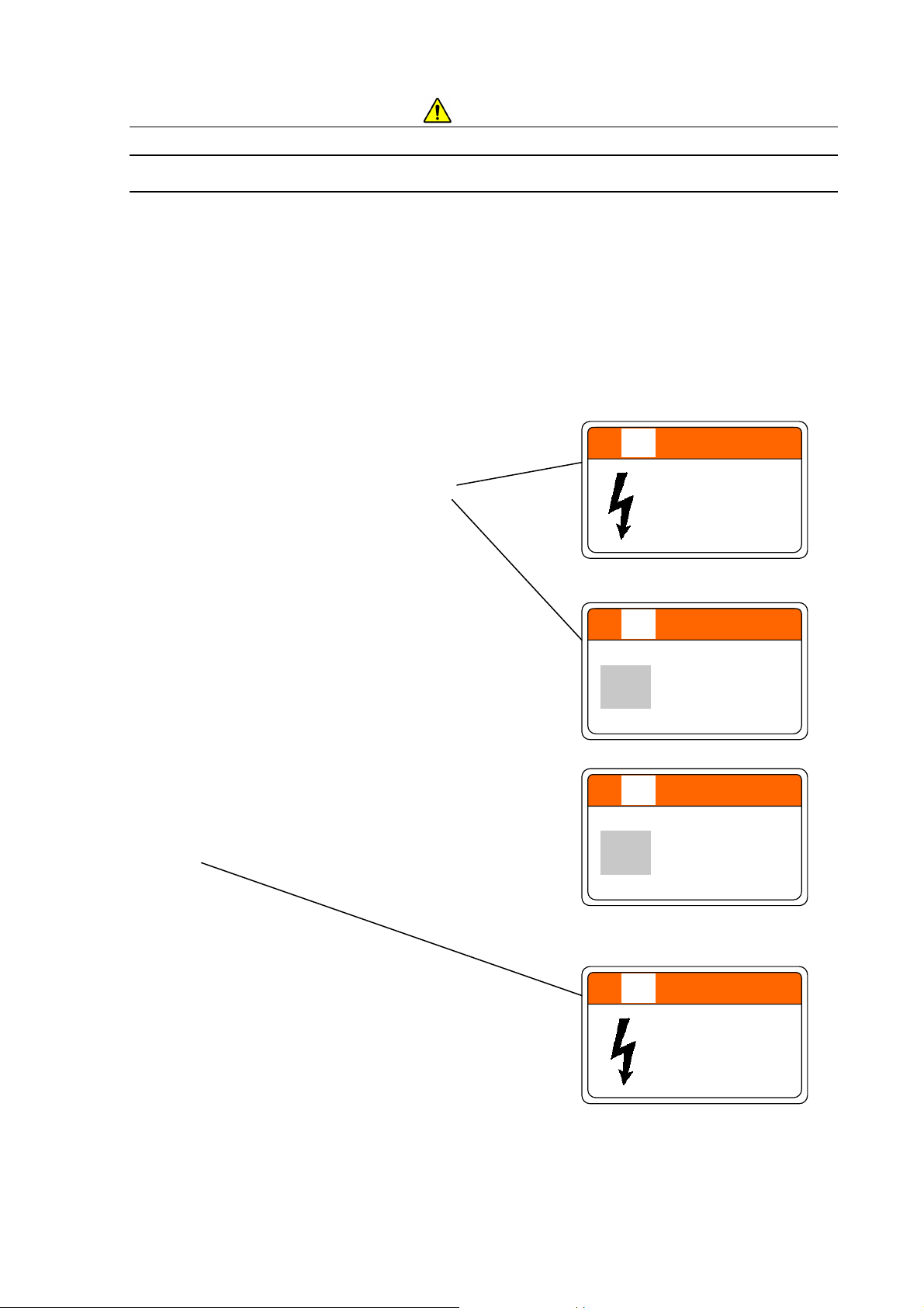
WARNING
Hazardous voltage inside
Can cause death or severe injury.
Do not remove the cover.
For Manual Stage
P/N 52E-4125
For Motor drive Stage
WARNING
Beware of heavy load! (65kg)
Can cause injuries.
When lifting the heavy load do
carefully by two or more
persons not to jam hands or
feet.
P/N 55E-2764
WARNING
Beware of heavy load! (68kg)
Can cause injuries.
When lifting the heavy load do
carefully by two or more
persons not to jam hands or
feet.
P/N 55E-4104
WARNING
Hazardous voltage inside
Can cause death or severe injury.
Do not remove the cover.
P/N 52E-4125
Locations of WARNING and CAUTION Labels on the TM3030Plus Main Unit (on the Sides)
SAFETY - 7
Page 21
For the Safe Handling of the System
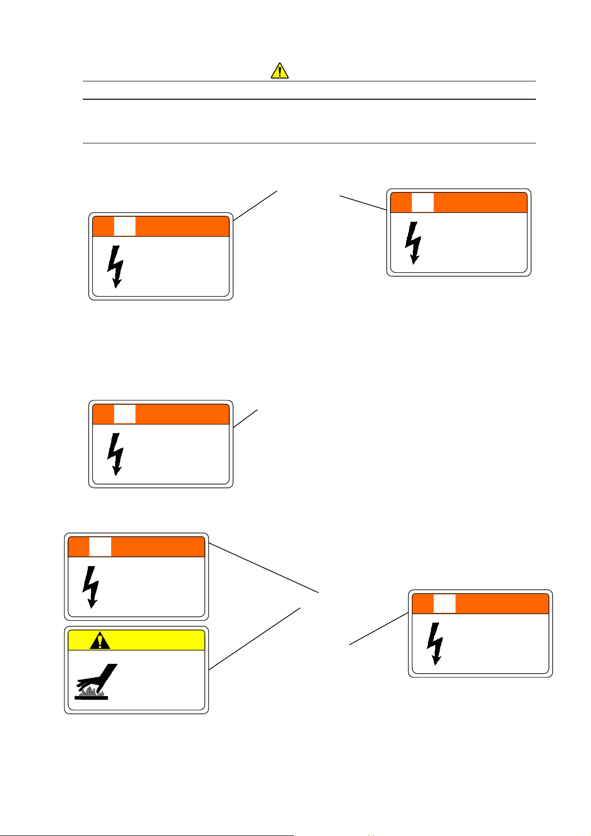
WARNING and CAUTION Labels on the System
(continued)
WARNING
WARNING
Hazardous voltage inside
Can cause death or severe injury.
Do not remove the cover.
P/N 52E-4125
Hazardous voltage inside
Can cause death or severe injury.
Do not remove the cover.
P/N 52E-4125
Location of WARNING Labels (on the Back)
WARNING
Hazardous voltage inside
Can cause death or severe injury.
Do not remove the cover.
WARNING
Hazardous voltage (15kV) inside
Can cause death or sev ere injury.
Do not resolve the electron gun.
CAUTION
Beware of high temperature
(About 90C)
Can cause burns.
Wait over 30 minutes for cooling
down after introducing air, when
replacing the filament.
P/N 52E-4125
P/N 52E-6731
P/N 55E-4102
Location of WARNING Labels (Upper View)
WARNING
Hazardous voltage inside
Can cause death or severe injury.
Do not remove the cover.
P/N 52E-4125
Location of WARNING Label (Front View)
SAFETY - 8
Page 22

For the Safe Handling of the System
To Av oid Se rious Prop erty Damage or Dam age to th e System
NOTICE
About the Power Supply
(1) Make sure the power supplied to the Tabletop Microscope is AC 100-240 V (Min. 90 V,
Max. 250 V), 500 VA or higher (50/60 Hz). Voltage fluctuations and superposed noise on
the power line can adversely affect the main unit.
(2) Be sure to connect the power line to a grounded power outlet. Verify that the grounding
for the outlet is connected with a grounding resistance of less than 100Ω Improper
grounding not only makes the system vulnerable to external noise; it is also dangerous due
to a potential for electric shock associated with floating voltages.
About the Cable Connection
To prevent a system malfunction, when connecting the power cable or a dedicated cable, be
sure to turn off the earth leakage breaker and the power switch. In particular, when plugging
or unplugging a USB cable, do so by turning off the PC. Remember that performing a “Safe
removal of hardware” step on the PC and receiving a “USB device can now be removed
safely” message does not mean that the USB has been turned off. Plugging or unplugging
the USB cable in this condition can potentially damage the system.
About the Detector
The semiconductor backscattered electron detector is vulnerable to damage. Scratches
made on the surface of the detector element can cause performance degradation. To prevent
damage to the semiconductor backscattered electron detector, when adjusting the height of
the specimen stub, be sure to use the special specimen height adjustment jig.
SAFETY - 9
Page 23

For the Safe Handling of the System
To Av oid Se rious Prop erty Damage or Dam age to th e System
(continued)
NOTICE
About Tur bo Molecular Pump
This instrument has a built-in Turbo Molecular Pump (TMP) whose fan rotor spins rapidly
(90,000 rpm) to maintain a vacuum inside the specimen chamber. So, any excessive shock
might damage TMP. For proper use, follow the precautions below.
(1) Filament replacement
Do not apply any shock to the electron gun part when opening/closing the electron
gun and performing beam axis alignment, which are needed in association with
filament replacement process.
(2) Specimen exchange
Carefully draw out/insert the specimen stage to avoid any impact to the instrument.
(3) Relocation of the instrument
Because this is a precision instrument and TMP should be fixed securely before
relocation, be sure to contact our service department when relocation is needed for
any reason. (As a rule, the customer is not allowed to relocate the instrument.)
Any malfunction might occur in TMP if excessive shock is applied to the instrument
without TMP secured.
(4) Handling of installation table
Do not apply excessive vibration or external shock to the table where the instrument is
placed.
Be careful not to apply any vibration to the table especially when doing some work on
it.
About Power Outages
An instantaneous voltage sag caused by a power outage or lightening can potentially damage
the basic software, the application software, or data. As a countermeasure against
instantaneous voltage sag, the use of the system with a PC battery mounted is recommended.
If a power outage occurs, turn off the earth leakage breaker and the power switch to guard
against voltage surges that can occur when power is restored.
When powe r i s r es to r ed , th e sys t em r eturns to the c ond ition that e xis t e d before the po we r
outage. If the power outage occurred in the midst of evacuation, the system automatically
resumes evacuation. If the system was open to the atmosphere, that condition is
maintained as is.
SAFETY - 10
Page 24

For the Safe Handling of the System
To Av oid Se rious Prop erty Damage or Dam age to th e System
(continued)
NOTICE
On the Power Supply for the PC
If power is shut off during access to the hard disk or other memory devices, a PC malfunction
can occur and the data and software stored on them can be destroyed. When finished with
the current operation, be sure to perform PC termination operations and then turn off the
power switch for the PC.
On Data Backup
In some cases, a PC failure or malfunction can cause data corruption. To avoid such a
problem, periodically copy the contents of the hard disk to another hard disk, CD-ROM, a
magneto-optical disk, or other external storage devices. Such periodic copying is referred to
as a backup. For further details on this topic, see the instruction manual supplied with the
PC.
About Application Software
Other application software programs should not be installed on the PC associated with the
system. Such programs, beyond producing unexpected operation screens, can adversely
affect the system and cause the system to fail to operate properly.
SAFETY - 11
Page 25

For the Safe Handling of the System
To Av oid Se rious Prop erty Damage or Dam age to th e System
(continued)
NOTICE
About the Computer Virus
If a program or data suddenly becomes corrupt, an unexpected operation occurs, or an
abnormal screen appears, the infection of the PC by a computer virus must be suspected.
The computer virus refers to a malicious program that surreptitiously invades the PC, runs
the PC uncontrollably, or damages data. By the same token, the program that
detects/eliminates computer viruses is referred to as anti-virus software.
The PC and the recording media provided with the system are checked with anti-virus software
before they are shipped from the factory.
PCs can be infected by a virus through interchangeable storage media, such as virus-infected
CDs, DVDs, a USB-connected flash memory units, or through the network. Do not use files that
pose a risk of infection by a computer virus.
Before connecting inte rchangeable storage media or the network, be sure to check it with
anti-virus software with the most up to date virus definitions. When connecting to the network,
HHT recommends the establishment of a firewall as an anti-computer virus measure between
the system and the network. Setting up a firewall is a customer responsibility. HHT does not
warrant that all computer viruses can be prevented by setting up a firewall.
If there are concerns about a computer virus infection, check your system by using anti-virus
software.
Procuring anti-virus software and removing the viruses are a customer responsibility.
Remember that some anti-virus programs may not be able to remove all computer viruses.
HHT does not warrant anti-virus software products themselves.
Some virus detection/eradiation programs, when made memory resident, can have an
adverse impact on the operation of the Tabletop Microscope. If a problem arises after
anti-virus software is installed, either uninstall the anti-virus software or make it non-resident
(by not registering it in the Startup program. Alternatively, perf orm operations such as
manually starting it when the Tabletop Microscope control program is not running, detecting
the viruses, and closing it when the virus detection process is finished, or conducting the
scanning process when the control program for the system is not running.
SAFETY - 12
Page 26

For the Safe Handling of the System
To Av oid Se rious Prop erty Damage or Dam age to th e System
(continued)
NOTICE
About Network Connection
For network connection, the PC is equipped with an Ethernet port. As connecting to the network
through the use of Ethernet requires sufficient knowledge on the network environment, perform
such a connection by consulting your network administrator.
(1) Providing a cable connection to the Ethernet port must be performed by either the system
installer or a service engineer. For these services, contact either the sales department
handling your account or the Service Department.
(2) When connecting the PC to a network, be sure to take adequate anti-computer virus
measures. For details, see the [About the computer virus] section in this chapter.
(3) The system is not supplied with an Ethernet cable; an appropriate cable should be
procured.
(4) Any change in settings for network connection should be performed with care. Unwittingly
changing the settings necessary for the operation of the system can render the system
inoperative.
(5) Do not install any special software necessary for network connection. Uninstalling it can
adversely impact the system or cause the system to fail to operate normally.
SAFETY - 13
Page 27

For the Safe Handling of the System
For the Proper Use o f t he System While Avoiding Minor
Damage to It
Installing the Control Application
If the control application is installed using a privilege other than the administrator privilege,
when a user logs in by using power user or general user privileges, the control application
may fail to run properly. To avoid this problem, be sure to install the control application by
using Administrator privileges.
Properties of the PC Screen
Do not change the screen resolution by means of PC screen property settings. Changing it can
cause the system to fail to display screens properly, produce color changes, and a failure of the
system to run properly. Note that the screen resolution is set according to the following
parameters (by using the [Control Panel] and [Display] and [Screen Resolution]):
Resolution: 1,280×800 pixels
About PC Freezing
If the PC freezes (the mouse and the keyboard won’t work) for some reason, on the
keyboard press the [Ctrl], [Alt], and [Delete] keys simultaneously, and shut down the system
by following the instructions that appear in the dialog box (software resetting).
After that, close Windows normally, turn off the main unit, and restart it. If this condition occurs,
any data up to that point will be lost. If the PC fails to restart after a software reset operation,
verify that the hard disk access indicator light is off, and press the Power button for a long time to
turn it off forcibly. Since turning off power when the hard disk is still running can damage the hard
disk and disable the PC from starting, this technique should be used only as a last resort. For a
description on the hard disk access indicator light, see the instruction manual supplied with the
PC.
About the Power Saving Feature and the Screen Saver
On the PC used in conjunction with the system, disable any screen saver, the display power
saving feature, and power management settings.
If any of these items are enabled, USB communications can be disrupted, causing the PC to
freeze.
SAFETY - 14
Page 28

For the Safe Handling of the System
For the Proper Use o f t he System While Avoiding Minor
Damage to It (continued)
Precautions on Operating the System
(1) When leaving the system unattended, turn off the Start button.
(2) Do not use large quantities of chemicals (such as conducting paste) that fix specimens
onto the specimen stub.
(3) When the system is not used, conduct evacuation at least once a week in order to
prevent any uneven distribution of the bearing grease used in the turbo molecular
pump. Also, keeping the system in a vacuum state helps to maintain the interior of the
system clean.
About the Environment around the System
In order to ensure a stable observation, use the system by paying attention to the
environment around the installation site for the system.
(1) Avoid installing the system in a place near power lines serving equipment such as a
large magnetic clutch and subject to sudden current or magnetic field changes.
(2) Install the system in a place away from sources of vibration, such as large machine
tools or transportation facilities (roads, railroads, and the like).
About Magnetic Fields Generated by a Notebook PC
Do not use the system by placing a notebook PC on its main unit. The effects of magnetic
fields generated from the notebook PC can cause image distortion during a high
magnification image observation.
About the Te mper ature and Humidity of the Room
The room in which the system is installed should be kept at a 15 to 30C room temperature
with a maximum humidity of 70% RH without condensation. The occurrence of water
condensation can cause system failure..
SAFETY - 15
Page 29

(For Korea only)
(한국대상)
Information about the attached chemical substances
부속화학물질에 관한 정보
The attached chemical substances listed below do not correspond to
the standard of classification of the harmful factor under the laws of Korea.
첨부된 아래의 리스트의 화학물질은 산업안전보건법 시행 규칙 별표 11 의 2 제 1
호에 따라 유해인자의 분류기준에 해당하지 않습니다.
Table Chemical substances for TABLETOP MICROSCOPE.
TABLETOP MICROSCOPE
Product Name
No. Part No.
품명
1 539-2132 Vacuum Grease (Electron Grease)
. 용 화학물질
Notes
Attached
Presence
비고
첨부 유무
Yes / No
유 / 무
SAFETY - 16
Page 30
Contents
PREFACE .............................................................................................................................. 1
ABOUT THIS INSTRUCTION MANUAL ............................................................................... 1
IMPORTANT ................................................................................................... IM PORTANT-1
Product Warranty ............................................................................................ IMPORT ANT-1
Installation, Relocation, and After Service ....................................................... IMPORTANT-3
Workshop and Training for Customers ............................................................ IMPORTANT-4
System Life ..................................................................................................... IMPORTANT-4
Disposal .......................................................................................................... IMPORTANT-4
Miscellaneous ................................................................................................. IMPORTAN T-5
For the Safe Handling of the System ....................................................... SAFETY- 1
General Precautions on Sa fety ........................................................................... SAFETY - 3
Warnings Provided in the Instruction Manual ...................................................... SAFETY- 4
WARNING ............................................................................................ SAFETY- 4
CAUTION ............................................................................................. SAFETY- 6
WARNING and CAUTION Labels on the System ................................................ SAFETY- 7
To Avoid Serious Property Damage or Damage to the System ........................... SAFETY- 9
NOTICE .............................................................................................................. SAFETY - 9
About the Power Supply ............................................................................... SAFETY- 9
About the Cable Connection ......................................................................... SAFETY- 9
About the Detector ....................................................................................... SAFETY- 9
About Turbo Molecular Pump ....................................................................... SAFETY - 10
About Power Outages .................................................................................. SAFETY - 10
On the Power Supply for the PC ................................................................... SAFETY- 11
On Data Backup ........................................................................................... SAFETY- 11
About Application Software .......................................................................... SAFETY- 11
About the Computer Vi rus ............................................................................ SAFETY - 12
About Network Connection ........................................................................... SAFETY - 13
For the Proper Use of the System While Avoiding Minor Damage to It ............... SAFETY- 14
Installing the Control Application .................................................................. SAFETY- 14
Properties of the PC Screen ......................................................................... SAFET Y - 14
About PC Freezing ....................................................................................... SAFETY - 14
About the Power Saving Feature and the Screen Saver ............................... SAFETY- 14
Precautions o n Op e rating the System .......................................................... SAFETY- 15
About the Environment around the System .................................................. SAFETY - 15
- i -
Page 31

About Magnetic Fields Generated by a Notebook PC ................................... SAFETY- 15
About the Temperature and Humidity of the Room ....................................... SAFETY- 15
(For Korea only) Information about the attached chemical substances ......... SAFETY - 16
PRECAUTIONS ON HANDLING ............................................................... PRECAUTIONS-1
1. Precautions on Usi ng the System ........................................................ PRECAUTIONS-1
2. General Items ...................................................................................... PRECAUTIONS-1
3. Emergency Action ................................................................................ PRECAUTIONS-2
4. Precautions on Ope rating the System .................................................. PRE C AUTIONS-2
5. Miscellaneous ...................................................................................... PRECAUTIONS-2
6. Notice on Disturbance by Electromagnetic Wave ................................. PRECAUTIONS-2
1 SPECIFICATIONS AND INSTALLATION CONDITIONS ......................................... 1- 1
1.1 Overview ............................................................................................................... 1- 1
1.2 Features ................................................................................................................ 1- 2
1.3 Specifications ........................................................................................................ 1- 3
1.4 Recommended PC Spec ifications ......................................................................... 1- 4
1.5 Installation Condition ............................................................................................. 1- 5
1.6 Items to be Prepared ............................................................................................. 1- 9
2 INSTALLATION AND SETUP .................................................................................. 2- 1
2.1 Connecting to the PC ............................................................................................ 2- 1
2.2 Setting up the PC .................................................................................................. 2- 1
2.2.1 Screen Settings ......................................................................................... 2- 1
2.3 Installation of the TM3030Plus Application Program .............................................. 2- 12
2.3.1 Installation of the Application Program ....................................................... 2- 15
2.3.2 Installation of the Instruction Manual ......................................................... 2- 20
2.3.3 Setup of the System Files .......................................................................... 2- 25
2.3.4 Confirmation of the Installation .................................................................. 2- 27
2.3.5 Installation of the USB Driver Software ...................................................... 2- 28
2.3.6 Confirmation of the USB Driver Software ................................................... 2- 29
2.3.7 Setup of the Observation Screen Size ....................................................... 2- 31
2.3.8 Adding a User Account .............................................................................. 2- 36
2.4 Uninstallation of the TM3030Pl us Application Program ......................................... 2- 39
2.4.1 Uninstallation of the Application Program .................................................. 2- 39
2.4.2 Uninstallation of the Instruction Manual ..................................................... 2- 42
2.5 Upgrading of the TM3030Plus Application Program .............................................. 2- 44
2.5.1 Upgrading of the Application Program ....................................................... 2- 44
2.5.2 Upgrading of the Instruction Manual .......................................................... 2- 57
- ii -
Page 32

2.6 About TM3030Plus Setup CD-ROM (Brief Explanation / Summary) ...................... 2- 66
2.6.1 Installing the Application ............................................................................ 2- 67
2.6.2 Upgrading the Application .......................................................................... 2- 68
2.6.3 Output Log Data ........................................................................................ 2- 69
2.6.4 About TM3030Plus Application .................................................................. 2- 69
2.6.5 Exit ............................................................................................................ 2- 69
3 SYSTEM CONFIGURATION ................................................................................... 3- 1
3.1 System Configuration ............................................................................................ 3- 1
3.2 Part Names ........................................................................................................... 3- 2
3.2.1 Main Unit ................................................................................................... 3- 2
3.2.2 Diaphragm Pump ...................................................................................... 3- 4
4 OPERATIONS ......................................................................................................... 4- 1
4.1 Summary of Operations ........................................................................................ 4- 1
4.1.1 Operation Units ......................................................................................... 4- 1
4.1.2 Operation Windows ................................................................................... 4- 2
4.2 Basic Operations ................................................................................................... 4- 4
4.2.1 Starting the System ................................................................................... 4- 5
4.2.2 Loading a Specimen and Adjusting its Height ............................................ 4- 8
4.2.3 Changing Specimens ................................................................................ 4- 13
4.2.4 Observation Condition Settings ................................................................. 4- 18
4.2.5 Signal Select / Observation Mode Settings ................................................ 4- 21
4.2.6 Starting Observation ................................................................................ 4- 25
4.2.7 Searching for Field of View ........................................................................ 4- 26
4.2.8 Setting a Magnification .............................................................................. 4- 30
4.2.9 Adjusting the Brightness / Contrast ............................................................ 4- 32
4.2.10 Coarse Focusing ...................................................................................... 4- 33
4.2.11 Fine Focusing .......................................................................................... 4- 35
4.2.12 Saving the Image Data ............................................................................. 4- 38
4.2.13 Checking the Image Data ......................................................................... 4- 41
4.2.14 Terminating the Image Observation ......................................................... 4- 41
4.2.15 Shutting Down the System ....................................................................... 4- 43
4.3 Detailed Description of Functions .......................................................................... 4- 45
4.3.1 Image Observation Area ............................................................................ 4- 45
4.3.2 Information / Comments Area .................................................................... 4- 45
4.3.3 File Menu ..................................................................................................
4.3
.4 Edit Menu .................................................................................................. 4- 48
4- 46
4.3.5 View Menu ................................................................................................ 4- 49
- iii -
Page 33

4.3.6 Setting Menu ............................................................................................. 4- 54
4.3.7 Stage Menu ............................................................................................... 4- 59
4.3.8 Maintenance Menu .................................................................................... 4- 62
4.3.9 Help Menu ................................................................................................. 4- 63
4.3.10 Start / Stop Button .................................................................................... 4- 64
4.3.11 View Mode Selection Button .................................................................... 4- 66
4.3.12 Observation Condition Selection Button ................................................... 4- 67
4.3.13 Signal Select / Observation Mode Selection Button ................................. 4- 70
4.3.14 Quick Save Button ................................................................................... 4- 73
4.3.15 Save Button ............................................................................................. 4- 75
4.3.16 Magnification Button ................................................................................ 4- 78
4.3.17 Preset Buttons ......................................................................................... 4- 79
4.3.18 Brightness Button..................................................................................... 4- 80
4.3.19 Contrast Button ........................................................................................ 4- 82
4.3.20 Auto B/C Button ....................................................................................... 4- 84
4.3.21 Focus Button ............................................................................................ 4- 85
4.3.22 Auto Focus Button ................................................................................... 4- 86
4.3.23 Image Shift Reset Button ......................................................................... 4- 87
4.3.24 Rotation Button ........................................................................................ 4- 87
4.3.25 Edit Button ............................................................................................... 4- 89
4.3.26 Minimize Button ....................................................................................... 4- 95
4.3.27 Exit Button ............................................................................................... 4- 96
4.3.28 Setting for Save Window .......................................................................... 4- 97
4.3.29 Save Image Window ................................................................................ 4- 97
4.3.30 Digital Zoom Window ............................................................................... 4- 99
4.3.31 Data Entry / Measurement Window .......................................................... 4-103
4.3.32 Image Balance Window ........................................................................... 4-108
4.3.33 Preset Magnification Window ................................................................... 4- 110
4.3.34 Auto B/C Adjustment Window .................................................................. 4- 111
4.3.35 Control Sensitivity Window ....................................................................... 4- 112
4.3.36 Beam Axis Alignment Window .................................................................. 4- 113
4.3.37 Observation Screen Size Window ............................................................ 4- 115
4.3.38 Astigmatism Correction ............................................................................ 4- 116
4.3.39 User Information Window ......................................................................... 4- 117
4.3.40 Version Information Window ....................................................................
4- 118
5 MA
INTENANCE ...................................................................................................... 5- 1
5.1 Filament Replacement .......................................................................................... 5- 2
5.1.1 Ultrasonic Cleaning with Organic Solvent (Volatile Solvent) ...................... 5- 10
- iv -
Page 34

5.2 Beam Axis Al ignment ............................................................................................ 5- 11
5.3 Condenser Lens Aperture Replacement ................................................................ 5- 21
5.4 Objective Aperture Replacement ........................................................................... 5- 25
5.5 Error Messages ..................................................................................................... 5- 29
5.5.1 Messages Displayed When the Application is Started ................................ 5- 29
5.5.2 Initial Startup Window (During Initialization) ............................................... 5- 31
5.5.3 Normal Observation Screen ...................................................................... 5- 34
5.5.4 Wait Message Window .............................................................................. 5- 51
5.5.5 Termination Process .................................................................................. 5- 53
6 REPLACEMENT PARTS ......................................................................................... 6- 1
6.1 Consumables ........................................................................................................ 6- 1
6.2 Limited Life Parts .................................................................................................. 6- 2
6.3 Spare Parts ........................................................................................................... 6- 4
7 3D-VIEW (Option) ................................................................................................... 7- 1
7.1 Functional Outline ................................................................................................. 7- 1
7.2 Measurement Method of 3D In formation ............................................................... 7- 3
7.3 Specifications ........................................................................................................ 7- 5
7.4 Installing and Uninstalling ...................................................................................... 7- 7
7.5 Environment Required for the Operation of 3D-Image Viewer ............................... 7- 7
7.6 Installing 3D-Image Viewer ................................................................................... 7- 8
7.7 Uninstalling 3D-Image Viewer ............................................................................... 7- 11
7.8 3D-Image Viewer Screen Configuration ................................................................ 7- 13
7.9 Menu Functions .................................................................................................... 7- 15
7.10 Image Settings View Function ............................................................................. 7- 23
7.11 Profile Settings View Function ............................................................................. 7- 28
7.12 Mouse Pointer ..................................................................................................... 7- 30
7.13 3D Viewer Functions ............................................................................................ 7- 31
7.14 Operation Procedures .......................................................................................... 7- 33
7.14.1 Procedure of 3D-Image Capture ............................................................. 7- 33
7.15 Displaying a 3D-Image by 3D-Image Viewer........................................................ 7- 39
7.15.1 Launching 3D-Image Viewer .................................................................. 7- 39
7.15.2 Importin g Image Data [Impo rt] ................................................................ 7- 40
7.16 Displaying a Profile and Measuring Roughness Parameters ................................ 7- 44
7.16.1 Measurement of Roughness [Line] .........................................................
7.1
6.2 Measurement of Roughness [Free] ........................................................ 7- 45
7- 44
7.16.3 Display of Roughness Parameters ......................................................... 7- 45
7.17 Measurement....................................................................................................... 7- 48
- v -
Page 35

7.17.1 Measurement of Distance ....................................................................... 7- 48
7.17.2 Measurement on Profile View ................................................................. 7- 50
7.18 Fix Function ......................................................................................................... 7- 53
7.18.1 Image Fix 3 points .................................................................................. 7- 53
7.18.2 Image Fix 9 points .................................................................................. 7- 56
7.18.3 Profile Fix ............................................................................................... 7- 58
7.19 Saving ................................................................................................................. 7- 60
7.19.1 Saving 3D Data being Worked On .......................................................... 7- 60
7.19.2 Saving an Image or Cross Profile on Image View as a BMP Format
Image File .............................................................................................. 7- 61
7.19.3 Saving an Image or Profile on Image View as a CSV Format
Image File .............................................................................................. 7- 61
7.19.4 Conversion into TDV Format .................................................................. 7- 62
7.20 Print ..................................................................................................................... 7- 63
7.21 Model Display in Three Dimensions ..................................................................... 7- 66
7.22 Calibration of 3D Measurement ........................................................................... 7- 71
7.23 Setting of Calibration Condition ........................................................................... 7- 72
7.24 Calibration Operations ......................................................................................... 7- 75
7.24.1 Calibration of X, Y ................................................................................... 7- 75
7.24.2 Calibration of Z ....................................................................................... 7- 77
7.24.3 Calibration of Flat ................................................................................... 7- 79
7.25 Height Calibration Using a 30-degree Tilted Specimen Stub ................................ 7- 80
7.25.1 Example of Procedure for Flat Calibration by 30-degree Tilted Specimen
Stub ........................................................................................................ 7- 80
7.25.2 Example of Procedure for Z Calibration by 30-degree Tilted Specimen
Stub ........................................................................................................ 7- 83
APPENDIX ........................................................................................................... Appendix-1
APPENDIX 1 Roughness Parameters ................................................................ Appendix-1
APPENDIX 2 List of Messages........................................................................... Appendix-4
- vi -
Page 36

PRECAUTIONS ON HANDLING
For safety, please comply with the following precautions:
1. Precautions on Using the System
WARNING (1) Do not remove the cover from the main unit.
Maximum voltages of AC 240 V and DC 15 kV prevail inside the main
unit, potentially causing severe injury or death from electric shock when
touched.
WARNING (2) Connect the grounding wires properly.
An improper grounding wire connection poses a potential electric shock
hazard beyond a failure of the system to run correctly.
WARNING (3) When stopping abnormally, the diaphragm pump remains hot, posing a
potential hazard of burns. In the event of a diaphragm pump problem,
contact a service engineer without touching it.
CAUTION (4) Cor r ectly measure and set the specimen size and height. An incorr ect
setting can potentially damage the specimen or components inside the
specimen chamber.
CAUTION (5) The turbo molecular pump is a limited life item. It should be replaced
after five years. When the bearings reach the end of their life, abnormal
heat generation, an abnormal noise, or abnormal stoppage can occur.
When replacing the TMP, please contact the Service Department.
CAUTION (6) The diaphragm pump is a limited life item. It should be overhauled after
five years. When the diaphragm reaches the end of its life, abnormal
heat generation, an abnormal noise, or abnormal stoppage can occur,
causing the entire pump to stop running. When having the DP
overhauled, please contact the Service Department.
2. General Items
System service operations other than those which are provided in this Instruction Manual
should be delegated to service engineers.
PRECAUTIONS - 1
Page 37

3. Emergency Action
3a. Turn off the POWER switch located on the main unit.
3b. Unplug the power cord from the outlet.
3c. Contact a service engineer.
4. Precautions on Operating the System
4a. When leaving the system unattended, turn off the accelerating voltage.
4b. To avoid contamination of a specimen, do not use large amounts of a chemical
(such as conducting paste) that fixes the specimen onto the specimen stand.
5. Miscellaneous
The room in which the system is installed should be maintained under the following
conditions even when the system is idle:
Room temperature: 15°C to 30°C
Humidity: 45 to 70% RH (no condensation)
If the system is not used for a long time, leave it in an evacuated condition instead of opening
the specimen chamber to the atmosphere.
6. Notice on Disturbance by Electromagnetic Wave
Though this instrument is nothing of the sort which gives off electromagnetic wave
intentionally, electromagnetic wave is slightly emitt ed from electronic cir cuit in this instr ument.
Therefore, equipment which is capable of being interfered with by electromagnetic noise
must not be installed near the instrument.
Also, this instrument may cause an image trouble or malfunction if it receives external
electromagnetic noise. The room in which this instrument has been installed must be
controlled so that nobody will bring the following electric apparatus* into the room.
* Apparatus which will transmit radio wave such as specified low-power equipment including
mobile phone, transceiver and cordless phone.
PRECAUTIONS - 2
Page 38

1 SPECIFICATIONS AND INSTALLATION CONDITIONS
1.1 Overview
The TM3030Plus is a tabletop microscope for the fine specimen image observation by
irradiating the specimen with the narrow-focused electron beam, and detecting secondary
electron and backscattered electron so as to be magnified and displayed on screen. The
main feature of this system is observation ability with high-magnification which cannot be
done with the optical microscope and it permits to get three-dimensional images with great
focal depth. Downsizing the traditional electron microscope and simplifying the operations,
even beginners who never used electron microscopes are allowed to use this Tabletop
Microscope easily.
Figure 1.1 External View of the TM3030Plus
1 - 1
Page 39

1.2 Features
TM3030Plus has the following main features:
1. A compact desktop type.
2. Provides a great focal depth and permits high magnification observation when compared
with an optical microscope.
3. Elimination of cumbersome preparation of samples.
4. The capacity to mount specimens up to 70 mm across and 50 mm thick.
5. PC-based operation and the automated focus/brightness adjustment function.
6. A quick 3-minute starting time.
7. Only an indoor power supply is required. (AC100 to 240 V : 5 A or less).
8. Able to observe various targets by selecting observation mode and condition.
1 - 2
Page 40

1.3 Specifications
Table 1.3 Specifications
1 Accele rating voltage 5 kV, 15 kV
Magnification 15x to 60,000x (image display magnification: 43steps (*1))
2
Maximum specimen
3
size
Maximum specimen
4
thickness
5 Specimen stage X:35 mm, Y:35 mm (X, Y only)
6 Electron gun Pre-centered cartridge filament
7 Stigma correction coil Provided
8 Image shift ±50 μm (15 kV mode: D=4.5 mm)
Detector High-sensitivity semiconductor backscattered electron
9
10 Control CPU method Notebook PC + dedicated microcomputer control
Monitor
11
(recommended)
12 Image data recording Hard disk mounted on PC, and other recording media
13 Recording pixels 1280×960 pixels (max.) / 640×480 pixels
14 Data display Micron marker, file No., date, comments
15 Automated function Auto brightness control, auto focusing adjustment
Auxiliary operation
16
function
Vacuum pump Compact turbo molecular pump: 30 l/s
17
18 Vacuum detector Pirani gauge
19 Frequency 50/60 Hz
Main unit power
20
supply
Dimensions/weight Main unit:
21
(*1) Magnification steps
15x, 18x, 20x, 25x, 30x, 40x, 50x, 60x, 80x, 100x, 120x, 150x, 180x, 200x, 250x, 300x,
400x, 500x, 600x, 800x, 1,000x, 1,200x, 1,500x, 1,800x, 2,000x, 2,500x, 3,000x,
4,000x, 5,000x, 6,000x, 7,000x, 8,000x, 9,000x, 10,000x, 12,000x, 15,000x, 18,000x,
20,000x, 25,000x, 30,000x, 40,000x, 50,000x, 60,000x
(*2) [D] denotes the distance between the specimen surface and the BSE detector.
Item Product Specifications
(digital zoom 2x, 4x), The minimum magnification depends
on the accelerating voltage, D (*2), and the screen size.
70 mm (diameter)
50 mm
detector
High-sensitivity secondary electron detector in the low
vacuum mode
LCD attached to the notebook PC (15-inch screen)
Raster rotation
Magnification preset (2 steps)
3
Diaphragm pump: 1 m
/h
AC 100 to 240 V (Min. 90 V, Max. 250 V), 500 VA
Built-in earth leakage breaker (5 A/(15 mA)): 3P outlet
connection
330(W)×606(D)×565(H) 65 kg (manual stage)
330(W)×633(D)×565(H) 68 kg (motor drive stage)
Diaphragm pump: 145×256×217 4.5 kg
1 - 3
Page 41

1.4 Recommended PC Specifications
Table 1.4 Recommended PC Specifications
Item Details
PC Recommended PC specifications
®
OS: Windows
CPU: Intel
Memory capacity: 2 GB minimum
Display resolution: WXGA 1366 × 768 pixels (1677 million colors)
Display: 15-inch screen
Interface connector: USB2.0/3.0 PC-card slots (IEEE 1394 (6 pin) or Oxford
EDX) is indispensable.
File device: HDD, DVD-ROM drive installed
7 Professional (64 bit)
®
Core™ i5-2520M (or greater)
NOTE
: A PC display resolution of 1366 × 768 pixels or less may cause the application to
fail to start.
The use of a high-resolution monitor, such as SXGA (1280 × 1024 pixels), SXGA +
(1400 × 1050 pixels), etc. may render the size of observation images smaller.
Setting these monitors in the stretch mode, observation screens can be blurred.
1 - 4
Page 42

1.5 Installation Condition
Install the TM3030Plus in the place of the following condition:
Table 1.5 Installation Conditions
Item Installation Conditions
General
requirements
Amplitude
(Vibration)
Magnetic
field
Flat location
1.
Avoid liquids
2.
Avoid external shock
3.
Avoid heat sources
4.
Avoid strong magnetic field (vertically from system: 15 mT, horizontally
5.
from system: 5 mT)
Avoid strong electric field
6.
Avoid dust
7.
Avoid vibration (follow the instructions below)
8.
Meet the following amplitude value for the installation site. The allowable
value is defined as the amount of image blurring is 0.2 mm or less in
photography at a magnification of 5,000x.
Allowable amplitude value (*)
Frequency 7 Hz, 4.0 µm p-p or less
7 Hz < frequency 10 Hz, 1.5 µm p-p or less
2
10 Hz < frequency, 2.0 cm/s
or less
Meet the following stray magnetic field value for the installation site. The
allowable value of AC magnetic field is defined as the amount of image
distortion (elongation, shrinkage, or bending) is 0.5 mm or less in
photography at a specified magnification or specified focus position
(D=4.5 mm). If D becomes longer, it becomes the more susceptible to the
influence of a stray magnetic field, and the allowable value of stray
magnetic fields becomes smaller.
Allowable stray magnetic field for the TM3030Plus (*)
Accelerating voltage: 5 kV
Magnification: 2 kx
D:4.5 mm
Accelerating voltage: 15 kV
Magnification: 5 kx
D:4.5 mm
AC magnetic field
(nT)
Horizontal Vertical Horizontal Vertical
376 607 425 686
289 369 327 417
1 - 5
DC magnetic field
fluctuation (nT)
(Peak-to-Peak)
Page 43

Noise Meet the following noise level for the installation site. The allowable level
is defined as the amount of image blurring is 0.2 mm or less in
photography at a magnification of 5,000x.
Allowable noise level (*)
75 dB or less (frequency 150 Hz) [C characteristics: 72 dB or less
(frequency 150 Hz)]
Ambient
15 to 30C (⊿t = ±2.5C/h or less)
temperature
Ambient
45 to 70 [%RH] or less. (No condensation)
humidity
Main unit
power supply
Single-phase AC 100 to 240 V (Min. 90 V, Max. 250 V), 500 VA,
50/60 Hz
3P outlet (grounding resistance of less than 100 )
Installation
800 mm × 1,200 mm or wider
area
* Allowable values of Amplitude/Magnetic field/Noise are specified based on the amount of
image blurring of an image.
In Fast Mode, scanning speed is different from that in other modes, so the amplitude of the
image may become large.
WARNING
: Using the system at a humid or dusty place can result in electric shock or
fires. For installation, prevent a place close to a sink or a humidifier, a
humid basement room, and a dusty or smoky place.
WARNING
: When connecting the main unit to the power supply, be sure to use the
grounded power cable that satisfies law and rule at the site.
Using an unspecified power cable can potentially cause electric shock.
Also, be sure to connect the power cable to a grounded power outlet.
If a grounded power outlet is not available for some reason, prepare a
grounded power strip or a conversion adapter. In such a case, be sure to
provide an appropriate grounding. Use a grounding wire with a minimum
core wire size of 2.0 mm. In addition, for connection use screws with a
minimum screw diameter of M4 and a thread count of 3. Be sure to plug
it in securely.
1 - 6
Page 44

WARNING
WARNING
: The system is a heavy object weighing approximately 65 kg (For Manual
Stage) / 68 kg (For Motor drive Stage). Install the system on a table with
a minimum load bearing capacity of 100 kg. Installing it on a table with
an inadequate load bearing capacity can cause the table to break, which
can result in unexpected injury beyond damage to the system.
To avoid injury from the falling or toppling of the system, do not install the
system in an unstable place or a place liable to fall or toppling due to an
earthquake or other events.
Install the system as it has a space of not less than 200 mm on the left
side so that the center of the gravity of the system is positioned near the
center of the table.
Do not install the device when delivering and do not transfer the device
after installation. Our engineer must carry it out.
: As a rule, do not move the diaphragm pump because it is a heavy load
of 4.5 kg. When moving it by necessity, move it carefully after
considering the length of piping and cable, the safety to one's foot, and
impact to the pump.
1 - 7
Page 45

For layout, see Figure 1.5 below.
Power supply & grounding
* Recommended
Table layout
256
Diaphragm
pump
Main unit
Grounded power cable
145
USB cable
Notebook PC
power cable
(2.5 m)
250
800
PC
606(Manual Stage)/633(Motor Drive Stage)
200
330
374
1200
Units: mm
Recommended table size: 1200(W)×800(D)×700(H) mm
Minimum table size: 1000(W)×800(D)×700(H) mm
Withstand load: 100 kg or more
* The Chair is not included in the size
* Dimensions is reference
Figure 1.5 Layout Diagram (Example)
1 - 8
Page 46

1.6 Items to be Prepared
Before the installation of TM3030Plus, prepare the following items.
Table 1.6 Customer-provided Items
PC Recommended PC (Refer to 1.4 Recommended PC Specifications)
Table
Recommended table
Size: 1,200 mm (W) × 800 mm (D) × 700mm (H) or larger
Withstand load: not less than 100 kg
Others: Flat, No casters
Others Ethyl alcohol
Metal polishing agent (Recommended supplier : Ted Pella
http://www.tedpella.com/material_html/polish.htm#pikal,
Part name : PIKAL(paste))
Ultrasonic cleaning system
Blower
1 - 9
Page 47

2 INSTALLATION AND SETUP
2.1 Connecting to the PC
Connect the main unit and a PC as shown in the figure below.
1. Connect the USB cable coming from the main unit to the PC USB port.
Figure 2.1 Connecting a USB Cable to the PC
2. Plug the power cable of the PC in a customer-provided outlet.
3. Plug the power cable of the main unit in a customer-provided outlet.
2.2 Setting up the PC
2.2.1 Screen Settings
NOTE
1. Click the [Control Panel] from the [Start] button located in the lower left of the
: The setup process and the reference screen images described in this chapter are
designed for the PC belonging to the TM3030Plus main unit. Unspecified PCs may
require a different way for setup and show different screen images from those of
this chapter. In such a case, follow your PC’s instruction manual.
desktop.
2 - 1
Page 48

Click
Figure 2.2.1-1 Start Button Window
2. Select [Small icons] from [View by] pull-down menu of [Control Panel].
Click
Figure 2.2.1-2 Adjust your computer’s settings Window
2 - 2
Page 49

3. The following window appears. Click the [Personalization] icon.
Click
Figure 2.2.1-3 Adjust your computer’s settings Window
4. Scroll down and click the [Windows 7 Basic] icon.
Scroll down
Figure 2.2.1-4 Change the visuals and sounds on your computer Window
2 - 3
Page 50

5. The window becomes black-and-white in a few seconds and recovers. Confirm the
[Windows color] becomes [Windows 7 Basic] and the [Screen saver] becomes [None].
Click
Figure 2.2.1-5 Change the visuals and sounds on your computer Window
NOTE
: TM3030Plus application program is recommended to be used with the setting
mentioned above. With using the [Windows Aero] function, observation screen
imaging speed may be reduced and it may prevent normal observation.
6. The following window appears. Click the [Screen saver] icon located in the lower right of
the screen and click the [Change power settings] located in the lower left of the [Screen
Saver Settings] window.
Click
Figure 2.2.1-6 Screen Saver Settings Window
2 - 4
Page 51

7. The following window appears. Click of the [Show additional plans] to select [High
performance], and click [Change plan settings].
Figure 2.2.1-7 Select a power plan Window
8. The [Change settings for the plan: High performance] menu is displayed. Select [Never]
in the [Dim the display], [Turn off the display] and [Put the computer to sleep] items.
Then, click the [Save changes] button.
Click(Back to Figure 2.2.1-7)
NOTE
Figure 2.2.1-8 Change settings for the plan: High performance Window
: Configure the same above setting in the [Balanced] and [Power saver] modes.
After all the setting is done, set [Select a power plan] to [High performance].
2 - 5
Page 52

9. Back to the [Power Options], and click [Choose what closing the lid does].
Click
Figure 2.2.1-9 Select a power plan Window
10. The following window appears. Change the setting of [On battery] and [Plugged in] for
[When I press the power button] to [Shut down]. Change the setting of [On battery] and
[Plugged in] for [When I close the lid] to [Do nothing].
Then, click the [Save changes] button.
Change to [Shut down]
Change to [Do nothing]
Click
Figure 2.2.1-10 Define power buttons and turn on password protection Window
2 - 6
Page 53

NOTE
: When this application is running, do not use the screen saver or do not leave the
PC in the sleep or standby mode. If any of these actions are taken, USB
communication will be disrupted on Windows and application may not work
normally or image data may be lost during capturing.
When this communication error occurred, restart the application.
11. Return to the Select a power plan window and click [Personalization] and then [Display]
in the lower left of the window.
Click
Figure 2.2.1-11 Select a power plan Window
Click
Figure 2.2.1-12 Change the visuals and sounds on your computer Window
2 - 7
Page 54

12. The following window appears. Click [Set custom text size (DPI)].
Click
Figure 2.2.1-13 Make it easier to read what’s on your screen Window
13. Confirm the setting is same as bellow (9 point Segoe UI at 96 pixels per inch. Scale to
this percentage of normal size: 100%) and click the [OK] button.
Figure 2.2.1-14 Custom DPI Setting Window
14. Back to the Display window and click the [Adjust resolution].
Click
Figure 2.2.1-15 Make it easier to read what’s on your screen Window
2 - 8
Page 55

15. Confirm the setting is the same as bellow, and click the [OK] button.
Display: 1.Mobile PC Display
Resolution: recommended size of arranged PC
Orientation: Landscape
Figure 2.2.1-16 Change the appearance of your display Window
In the case of using English as a Display language for TM3030Plus application, please
operate the settings below.
16. Click [Control Panel] from the [Start] button in the left of the desktop window.
17. The following window appears. Click [Region and Language].
2 - 9
Page 56

Click
Figure 2.2.1-17 Adjust your computer’s settings Window
18. The Region and Language window appears. Select [Administrative] tab and click
[Change system locale] button in the [Language for non-Unicode programs].
Figure 2.2.1-18 Region and Language Window
19. The Region and Language Settings window appears. From the pull down list of [Current
system locale], select [English (United States)] and click the [OK] button.
2 - 10
Page 57

Figure 2.2.1-19 Region and Language Settings Window
20. The following window appears. Click the [Restart now] button.
Figure 2.2.1-20 Change System Locale Window
21. After restarting, open the [Administrative] tab in the Region and Language window and
confirm that the [Language for non-Unicode programs] is [English (United State)].
2 - 11
Page 58

Figure 2.2.1-21 Region and Language Window
NOTE
: If not performing the above settings, texts may be corrupted in the TM3030Plus
application.
This is the end of the PC setup. About installation of TM3030Plus application program, refer
to 2.3.1 Installation of the Application Program.
2.3 Installation of the TM3030Plus Application Program
NOTE
: When installing the application, follow these precautions:
1. Log in as “TM3030PlusUSER”.
2. Do not connect the main unit to the PC with USB cable before completion of
the installation.
Main unit USB cable PC
Figure 2.3-1 Prohibition of the Connecting Main Unit to the PC
2 - 12
Page 59

1. Turn on the PC and log in as “TM3030PlusUSER”. If no other user login name is set
additionally, the login window does not appear.
2. Insert the TM3030Plus setup CD-ROM into the CD/DVD drive.
3. The following window appears. Click the [Run SETUP.exe] icon.
Figure 2.3-2 AutoPlay Window
2 - 13
Page 60

4. TM3030Plus Setup Tools starts automatically. If the User Account Control window
appears, click the [Yes ] button.
Click
Figure 2.3-3 User Account Control Window
5. The following window appears. Input Serial Number of the TM3030Plus in the dialog box
and click the [OK] button.
Serial Number is listed on the product nameplate located on the back of the main unit.
Figure 2.3-4 Input Serial Number Dialog Box
Figure 2.3-5 Product Nameplate
2 - 14
Page 61

2.3.1 Installation of the Application Program
1. The following window appears. Click the [Installation for TM3030Plus application] button.
Click
Figure 2.3.1-1 TM3030Plus Setup Tools Window (Main Menu)
2. The following window appears. Click the [Installation of application program.] button.
Click
Figure 2.3.1-2 TM3030Plus Setup Tools Window (Installation)
2 - 15
Page 62

NOTE : When this application is already installed, the message window shown below
appears. In this case, click the [OK] button to close the window. When any
application failure occurs and so the application is to be repaired, refer to 2.5.1 2
Repairing.
Figure 2.3.1-3 Message Window
3. The following window appears. Select [English [United States]] and click the [OK] button.
Figure 2.3.1-4 Choose Setup Language Window
4. The following window appears. Wait until the preparing finishes.
Figure 2.3.1-5 Preparing to Install Window
2 - 16
Page 63

5. The following window appears. Click the [Next] button.
Click
Figure 2.3.1-6 InstallShield Wizard Window
6. The following window appears. Input a User Name and Organization. The items saved
before will be displayed by default. In this case, they can be used without changed.
Click the [Next] button.
Click
NOTE
Figure 2.3.1-7 Customer Information Window
: For using with all login user, select [Anyone who uses this computer (all users)] as
[Install this application for].
When selecting [Only for me (TM3030PlusUSER)], only the user who is now
installing the application can use it.
2 - 17
Page 64

7. The following window appears. Click the [Install] button.
Click
Figure 2.3.1-8 Ready to Install the Program Window
8. The following window appears, and the application program starts to be installed.
Do not click the [Cancel] button during this installation.
Figure 2.3.1-9 Installing TM3030Plus Window
2 - 18
Page 65

9. When installing, the following [Windows Security] window may appear. In such a case,
click the [Install] button.
Click
Figure 2.3.1-10 Windows Security Window
10. The following window appears. Click the [OK] button.
Figure 2.3.1-11 Attach Your Device Window
11. W hen the install process is completed, the following window appears.
Click the [Finish] button.
Click
Figure 2.3.1-12 InstallShield Wizard Completion Window
2 - 19
Page 66

2.3.2 Installation of the Instruction Manual
1. The following window appears. Click the [Installation for TM3030Plus application] button.
Figure 2.3.2-1 TM3030Plus Setup Tools Window (Main Menu)
2. Install the instruction manual. Select [Installation of the instruction manuals] from the
Installation menu of the TM3030Plus Setup Tools.
Click
Figure 2.3.2-2 TM3030Plus Setup Tools Window (Installation)
2 - 20
Page 67

NOTE : When this Instruction Manual is already installed, the window shown below
appears. In this case, click the [OK] button to close the window. After uninstalling
the Instruction Manual, re-install it. For the details of the uninstall process, refer to
2.4.2 Uninstallation of the Instruction Manual.
Figure 2.3.2-3 Message Window
3. The following window appears. Click the [OK] button.
Figure 2.3.2-4 Choose Setup Language Window
4. The following window appears. Wait until the preparing finishes.
Figure 2.3.2-5 Preparing to Install Window
2 - 21
Page 68

5. The following window appears. Click the [Next] button.
Click
Figure 2.3.2-6 InstallShield Wizard
6. The following window appears. Click the [Next] button.
Figure 2.3.2-7 Customer Information Window
Click
NOTE
: For using with all login user, select [Anyone who uses this computer (all users)] as
[Install this application for].
When selecting [Only for me (TM3030PlusUSER)], only the user who is now
installing the application can use it.
2 - 22
Page 69

7. The following window appears. Click the [Install] button.
Click
Figure 2.3.2-8 Ready to Install the Program Window
8. The instruction manual starts to be installed.
Do not click the [Cancel] button during this installation.
Figure 2.3.2-9 Installing TM3030Plus Manual Window
2 - 23
Page 70

9. When the install process is completed, the following window appears. Click the [Finish]
button.
Click
Figure 2.3.2-10 InstallShield Wizard Completion Window
2 - 24
Page 71

2.3.3 Setup of the System Files
1. The following window appears. Click the [Installation for TM3030Plus application] button.
Figure 2.3.3-1 TM3030Plus Setup Tools Window (Main Menu)
2. Setup the System Files. Select [Setup of system files] from the Installation menu of the
TM3030Plus Setup Tools.
Click
Figure 2.3.3-2 TM3030Plus Setup Tools Window (Installation)
2 - 25
Page 72

3. After finishing the installation, the following window appears. Click the [OK] button.
Figure 2.3.3-3 System Installed Window
4. Click the [Exit] button in the [TM3030Plus Setup Tools] window.
Figure 2.3.3-4 TM3030Plus Setup Tools Window (Installation)
Click
5. Tak e out the setup CD-ROM from the CD/DVD drive.
NOTE
: Keep the TM3030Plus setup CD-ROM at hand because factory default system
data is saved in it.
2 - 26
Page 73

2.3.4 Confirmation of the Installation
1. Confirm the [TM3030Plus] shortcut icon exists on the desktop.
Figure 2.3.4-1 TM3030Plus Shortcut Icon
2. Confirm the [TM3030Plus] is added in the program menu of the [Start] button.
Figure 2.3.4-2 Confirmation of Installation
3. Substantial application file is installed in the [C:¥Program Files(x86)¥TM3030Plus¥]
folder. Do not edit, move, or delete the installed file.
2 - 27
Page 74

2.3.5 Installation of the USB Driver Software
Perform the following operations after installation of TM3030Plus application.
1. Shut down the main unit.
Connect the USB cable coming from the main unit to the PC USB port.
Main unit
USB cable
PC
Figure 2.3.5-1 Connecting the Main Unit and the PC
2. Turn on the main unit. The Plug-and-Play function recognizes the USB device, and
displays the following message for a few seconds in the lower part of the screen.
Figure 2.3.5-2 Installing device driver software Message
3. After the USB device driver is installed successfully, t he following message appears.
Figure 2.3.5-3 SemUsb Device Message
2 - 28
Page 75

2.3.6 Confirmation of the USB Driver Software
1. Open [Device Manager] from [Control Panel] of the [Start] menu.
Figure 2.3.6-1 Device Manager Icon
* When [Device Manager] does not appear, select [Small icons] from [View by]
pull-down menu of [Control Panel].
Figure 2.3.6-2 Control Panel
Figure 2.3.6-3 Control Panel
2 - 29
Page 76

2. [Device Manager] appears. Confirm [SEM USB Device] exists in [Universal Serial Bus
controllers]. If it doesn’t exist, install the USB driver software again.
Figure 2.3.6-4 Device Manager Window
3. Close [Device Manager].
2 - 30
Page 77

2.3.7 Setup of the Observation Screen Size
NOTE
: When starting the TM3030Plus application program, follow these precautions:
1. Connect the main unit to the PC with a USB cable.
2. Start the application program after turning on the main unit. The application
doesn’t start when the main unit is shut down or the USB cable is unplugged.
(When initializing, this message appears.)
3. Do not shut down the main unit or unplug the USB cable while the application
is running.
1. Double-click the TM3030Plus shortcut icon on desktop to power up the main unit.
(2) Application starts.
USB cable
(1) Power UP
Main unit
PC
Figure 2.3.7-1 Connecting the Main Unit to the PC
2. The application starts up.
Figure 2.3.7-2 Application Startup Window
2 - 31
Page 78

3. After installing the application, when the application starts up first, the [No data found in
Initial File. Do you default to start up PC?] message appears. Click the [OK] button.
Click
Figure 2.3.7-3 Default to Start Up Window
4. The [Set up the observation screen size when the application has started.] message
appears. Click the [OK] button.
Click
Figure 2.3.7-4 Observation Screen Size Setup Window
5. The message [No User Setting File found. Do you default to start up PC?] message.
Click the [OK] button.
NOTE
Click
Figure 2.3.7-5 Default to Start Up Window
: When initializing, do not shut down the main unit or unplug the USB cable.
2 - 32
Page 79

6. When the application starts normally, the operation window appears.
Figure 2.3.7-6 Operation Window
7. Select [Observation Screen Size.] from the [Maintenance] menu in the operation window.
Figure 2.3.7-7 Maintenance Menu
2 - 33
Page 80

8. The Observation Screen Size window and a red line appear in the operation window.
Figure 2.3.7-8 Observation Screen Size Window
9. Measure the red line appearing in the operation window with a ruler.
NOTE
Figure 2.3.7-9 Measuring the Observation Screen Size
: Measure the red line in 0.5 mm increments. Otherwise a wrong value may input
and magnification of the observation screen may not be accurate.
2 - 34
Page 81

10. Input the length of the red line in the [Observation screen size] box of the Observation
Screen Size dialog, and click the [SET] button and the [Close] button.
* The observation screen size will change depending on the PC environment.
Click
Click
Figure 2.3.7-10 Observation Screen Size Window
11. Click the [Close] button to close the Observation Screen Size window.
12. Click the [X] button at the right side of the title bar in the operation window or select
[Exit] from the [File] menu to close the application program.
13. The following window appears. Click the [OK] button to close the application program.
Click
Figure 2.3.7-11 Application Closing Window
2 - 35
Page 82

2.3.8 Adding a User Account
1. When starting the application with a new Windows user account, perform the operations
described in [2.2.7 Screen Settings] for each account. For the operation to create a
Windows user account, see the instruction manual supplied for the PC.
2. Turn on the main unit. Double-click the TM3030Plus shortcut icon on the desktop.
Figure 2.3.8-1 TM3030Plus Shortcut Icon
NOTE
: Before launching an application, check the following items:
1. Make sure the PC is connected to the main unit with a USB cable.
2. Start the application when the main unit is powered on. The application cannot
be started if the main unit is turned off or the USB cable is unplugged (an
initialization message will be displayed).
3. When the application is being started, do not turn off the main unit or unplug
the USB cable.
3. The application starts up.
Figure 2.3.8-2 Application Startup Screen
2 - 36
Page 83

4. A [No User Setting File found. Do you default to start up PC?] message appears. Click
the [OK] button.
Click
Figure 2.3.8-3 Default to Start Up Window
5. When the application program starts normally, the following operation window appears.
For a description of image observation operations, see Chapter 4.
Figure 2.3.8-4 Operation Window
6. Select either the [X] button at the right edge of the title bar in the Operation window or
[Exit] from the [File] menu to close the application program.
2 - 37
Page 84

7. The following confirmation window appears. Click the [OK] button to close the application
program.
Click
Figure 2.3.8-5 Close the Application Window
2 - 38
Page 85

2.4 Uninstallation of the TM3030Plus Application Program
2.4.1 Uninstallation of the Application Program
NOTE
: Uninstall the TM3030Plus application program with a user name of
TM3030PlusUSER.
1. Open [Control Panel] from the Start menu.
2. Select [Programs and Features] from the [Control Panel].
Figure 2.4.1-1 Programs and Features Icon
3. The following window appears. Select [TM3030Plus] and click [Uninstall].
Figure 2.4.1-2 Uninstall or change a program Window
4. The following window appears. Click the [Yes] button.
2 - 39
Page 86

Figure 2.4.1-3 Programs and Features Window
5. The following window appears. Wait a moment.
Click
Figure 2.4.1-4 Windows Installer Window
6. When the following window appears, click the [Yes] button.
Figure 2.4.1-5 User Account Control Window
7. The following window appears and the uninstallation starts.
Click
Figure 2.4.1-6 Windows configures TM3030Plus Window
2 - 40
Page 87

8. After finishing the uninstallation, confirm the [TM3030Plus] is removed from the
[Programs and Features] window.
9. Close the [Programs and Features] window.
2 - 41
Page 88

2.4.2 Uninstallation of the Instruction Manual
NOTE
: Uninstall the instruction manual with a user name of TM3030PlusUSER.
1. Open [Control Panel] from the Start menu.
2. Select [Programs and Features] from [Control Panel].
Figure 2.4.2-1 Programs and Features Icon
3. The following window appears. Select [TM3030Plus Manual] and click [Uninstall].
Figure 2.4.2-2 Uninstall or change a program Window
4. The following window appears. Click the [Yes] button.
Figure 2.4.2-3 Programs and Features Window
2 - 42
Click
Page 89

5. The following window appears. Wait a moment.
Figure 2.4.2-4 Windows Installer Window
6. When the following window appears, click the [Yes] button.
Click
Figure 2.4.2-5 User Account Control Window
7. After the uninstallation process is finished, confirm the [TM3030Plus Manual] is removed
from the [Programs and Features] window.
8. Close the [Programs and Features] window.
2 - 43
Page 90

2.5 Upgrading of the TM3030Plus Applicat ion Program
NOTE
: When upgrading the application, follow these precautions:
1. Login as TM3030PlusUSER.
2. Do not connect the main unit to the PC with USB cable before upgrading the
application.
Main unit USB cable PC
Figure 2.5 Prohibition of the Connecting Main Unit to the PC
2.5.1 Upgrading of the Application Program
1. Upgrading
In the case where the conventional TM3030Plus application program is already installed
and later version needs to be installed, apply the following process:
NOTE
: Confirm the version of the TM3030Plus application program by seeing the
[Upgrade for TM3030Plus application] in the TM3030Plus Setup Tools. The
now-installing version is shown in the [Version Information] of the [Help] menu.
1a. Power up the PC and login as TM3030PlusUSER. If no other users is added, the login
window does not appear.
1b. Insert the TM3030Plus setup CD-ROM to the CD/DVD drive.
2 - 44
Page 91

1c. The following window appears. Click [Run SETUP.exe].
Figure 2.5.1-1 AutoPlay Window
1d. Easy install tool starts automatically. If the User Account Control window appears, click
the [Yes] button.
Click
Figure 2.5.1-2 User Account Control Window
2 - 45
Page 92

1e. The following window appears. Input Serial Number in the dialog box, and click the
[OK] button.
Serial Number is listed on the product nameplate on the back of the main unit.
Figure 2.5.1-3 Input Serial Number Dialog Box
Serial No.
Figure 2.5.1-4 Product Nameplate
1f. The following window appears. Click the [Upgrade for TM3030Plus application] button.
Click
Figure 2.5.1-5 TM3030Plus Setup Tools Window (Main Menu)
2 - 46
Page 93

1g. The following window appears. Click the [Upgrade of application program.] button.
Click
Figure 2.5.1-6 TM3030Plus Setup Tool s Window (Upgrade)
1h. The following window appears. Click the [OK] button.
Figure 2.5.1-7 Choose Setup Language Window
1i. The following window appears. Click the [Yes] button.
Figure 2.5.1-8 Continue Setup Window
2 - 47
Page 94

10 1j. The following window appears. Wait until the preparation finishes.
Figure 2.5.1-9 Preparing to Install Window
1k. The following window appears. Click the [Next] button.
Figure 2.5.1-10 Resuming the InstallShield Wizard Window
Click
2 - 48
Page 95

1l. The application starts to be installed. Do not click the [Cancel] button during this
installation process.
Figure 2.5.1-11 Installing TM3030Plus Window
1m. If the following window appears, click the [OK] button.
Figure 2.5.1-12 User Account Control Window
NOTE
: When the TM3030Plus application program (Setup.exe) is installed with the
TM3030Plus Setup tools, the User Account Control window does not appear
because the change of the setting has been permitted on the User Account Control
window upon the startup of the TM3030Plus Setup tools.
2 - 49
Page 96

1n. The following window appears. Click the [OK] button.
Figure 2.5.1-13 Attach Your Device Window
1o. When the installation is completed successfully, the following window appears. Click
the [Finish] button.
Click
Figure 2.5.1-14 InstallShield Wizard Completed Window
2 - 50
Page 97

2. Repairing of the Application Program
When installing the application program of the same version as already installed, the
following [Repair] program appears. Use this function when some trouble occur with the
application program.
NOTE
: Confirm the version of the TM3030Plus application program by seeing the
[Upgrade for TM3030Plus application] in the TM3030Plus Setup Tools. The
now-installing version is shown in the [Version Information] of the [Help] menu.
2a. Click the [Upgrade for TM3030Plus application] button of the following TM3030Plus
Setup Tools main menu.
Click
Figure 2.5.1-15 TM3030Plus Setup Tools Window (Main Menu)
2 - 51
Page 98

2b. The following window appears. Click the [Upgrade of application program.] button.
Click
Figure 2.5.1-16 TM3030Plus Setup Tool s Window (Upgrade)
2c. The following window appears. Click the [OK] button.
Figure 2.5.1-17 Choose Setup Language Window
2 - 52
Page 99

2d. The following window appears. Wait until the preparation finishes.
Figure 2.5.1-18 Preparing to Install Window
2e. The following window appears. Click the [Next] button.
Figure 2.5.1-19 Welcome to the InstallShield Wizard Window
Click
2 - 53
Page 100

2f. The following window appears. Select the [Repair] button, and click the [Next] button.
Click
Figure 2.5.1-20 Program Maintenance Window
2g. The following window appears. Click the [Install] button.
Figure 2.5.1-21 Ready to Install the Program Window
Click
2 - 54
 Loading...