

Page 1

WirelessIP 5000 User's Manual
(v2.0.0)
TD61-2472A
Hitachi Cable, Ltd.
Page 2

User's Manual
1. NAMES & FUNCTIONS OF DEVICE PARTS ..............................................................................1
1.1. DISPLAYED ICO NS..............................................................................................................................1
1.2. NUMBER PAD INPUT TABLE ...............................................................................................................3
1.2.1 Text input mode ...............................................................................................................................3
2. APPLICATION...................................................................................................................................6
2.1. POWER ON ........................................................................................................................................6
2.2. POWER OFF ......................................................................................................................................6
2.3. CALL ..................................................................................................................................................7
2.4. RECEIVE.............................................................................................................................................7
2.5. CONTACT LIST...................................................................................................................................8
2.5.1 New registration...............................................................................................................................9
2.5.1.1 Registration from a telephone number ..........................................................................................9
2.5.1.2 Registration from contact list menu ..............................................................................................9
2.5.1.3 Registration from search results ..................................................................................................11
2.5.1.4 Registration from a call log.........................................................................................................12
2.5.1.5 Registration from IM...................................................................................................................13
2.5.1.6 Registration from presence..........................................................................................................14
2.5.2 Call from contact list......................................................................................................................15
2.5.3 Group revision................................................................................................................................16
2.5.4 Erase one item from contact list.....................................................................................................18
2.5.5 Erase all..........................................................................................................................................19
2.6. IM ....................................................................................................................................................20
2.6.1 Inbox ..............................................................................................................................................21
2.6.2 New Message .................................................................................................................................26
2.6.3 Drafts..............................................................................................................................................28
2.6.4 Outbox............................................................................................................................................32
2.6.5 Setting ............................................................................................................................................36
2.7. CALL LOG ........................................................................................................................................37
2.7.1 Details ............................................................................................................................................38
2.7.2 Call log delete ................................................................................................................................38
2.7.3 Delete all data.................................................................................................................................39
2.7.4 Calling from the call log.................................................................................................................40
2.8. PRESENCE........................................................................................................................................41
2.8.1 User list ..........................................................................................................................................41
2.8.2 Block list ........................................................................................................................................45
2.8.3 Status..............................................................................................................................................49
2.8.4 Setting ............................................................................................................................................50
2.9. BASIC SETTINGS MENU ....................................................................................................................51
2.9.1 Sound/Vibration .............................................................................................................................51
2.9.2 Phone Lock ....................................................................................................................................53
2.9.3 Alarm .............................................................................................................................................54
2.9.4 Volume...........................................................................................................................................55
2.9.5 Error Lamp.....................................................................................................................................56
2.9.6 Information display ........................................................................................................................57
2.9.7 Advanced .......................................................................................................................................59
2.9.7.1 Time ............................................................................................................................................60
2.9.7.2 Brightness adjustment .................................................................................................................62
2.9.7.3 Font size ......................................................................................................................................62
2.9.7.4 Language setting .........................................................................................................................63
Hitachi Cable -i-
Page 3

User's Manual
2.9.7.5 Caller ID......................................................................................................................................63
2.9.7.6 User Data Reset...........................................................................................................................64
2.9.8 Courtesy mode On/Off...................................................................................................................64
2.9.9 KeyLock/ KeyUnlock ....................................................................................................................66
2.10. ETWORK ......................................................................................................................................67 N
2.10.1 Site Scan.......................................................................................................................................68
2.10.2 Ping Test ......................................................................................................................................69
2.10.2.1 Manual ........................................................................................................................................69
2.10.2.2 1st Proxy .....................................................................................................................................69
2.10.2.3 2nd Proxy ....................................................................................................................................70
2.10.2.4 Gateway ......................................................................................................................................71
2.10.2.5 TFTP server.................................................................................................................................71
2.10.3
Network Reload ...........................................................................................................................72
3.
VARIOUS OPERATION METHODS............................................................................................73
H
3.1. OLD FUNCTION..............................................................................................................................73
3.1.1 Hold................................................................................................................................................73
3.1.2 Hold release....................................................................................................................................73
C
3.2. ALLING METHOD...........................................................................................................................74
3.2.1 Internal extension call ....................................................................................................................74
3.2.2 Outside-line call .............................................................................................................................74
3.2.3 184/186 call....................................................................................................................................75
3.2.4 Operation methods using call mode ...............................................................................................76
3.2.4.1 Calling in call mode from the contact list ...................................................................................76
3.2.4.2 Calling in call mode from the incoming call log or outgoing call log.........................................76
3.2.5 Redial .............................................................................................................................................76
3.2.6 Speed dialing..................................................................................................................................77
3.2.7
Timer between digits......................................................................................................................77
4.
ACCESSORIES ................................................................................................................................79
4.1. ACCESSORY GUIDELINES.................................................................................................................79
4.2. ACCESSORIES COVERED..................................................................................................................79
4.3. AC POWER SUPPLY ADAPTOR..........................................................................................................79
4.4. USB CABLE (OPTION)......................................................................................................................80
4.5. INSTALLING THE BATTERY..............................................................................................................80
4.6. REMOVING THE BATTERY...............................................................................................................80
4.7. CHARGING WITH THE DESKTOP CHARGER .....................................................................................80
4.8. CHARGING WITHOUT THE DESKTOP CHARGER ..............................................................................81
4.9. LED .................................................................................................................................................81
5.
SAFETY INSTRUCTIONS..............................................................................................................82
5.1. WARNING ABOUT EMERGENCY SERVICES ......................................................................................82
5.2. WARNING ABOUT EXPLOSIVE GAS ..................................................................................................82
5.3. WARNING ABOUT THE IMPACT OF ELECT ROMAGNETIC SIGNALS..................................................82
5.4. WARNING ABOUT BATTERY HANDLING ..........................................................................................82
5.5. BATTERY SAFETY ITEMS .................................................................................................................82
APPENDIX SPECIFICATIONS
Hitachi Cable -ii-
..........................................................................................................83
Page 4
User's Manual
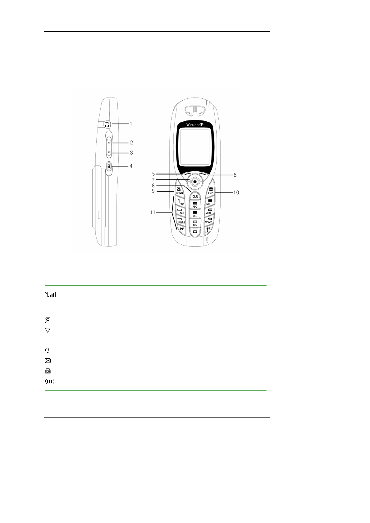
1. Names & Functions of Device Parts
Figure 1 shows side and front diagrams of the WirelessIP5000.
Figure 1
1.1. Displayed icons
Shows the reception signal strength. The more lines, the better the signal.
Out of service area shows that the location is outside the service area or is an environment where the
signals do not reach.
Shows that the phone is On in silent mode. This is displayed when the ringer is set to silent.
Shows that vibration mode is On. Sets the incoming call ringer to vibration
Shows that the alarm is On. Alarm clock setting
Displayed when there is an unread message.
Shows that the keys are locked. When this mode is On, key operation is disabled.
Shows the remaining battery capacity. The more lines, the more capacity remains.
Hitachi Cable 1/84
Page 5
User's Manual
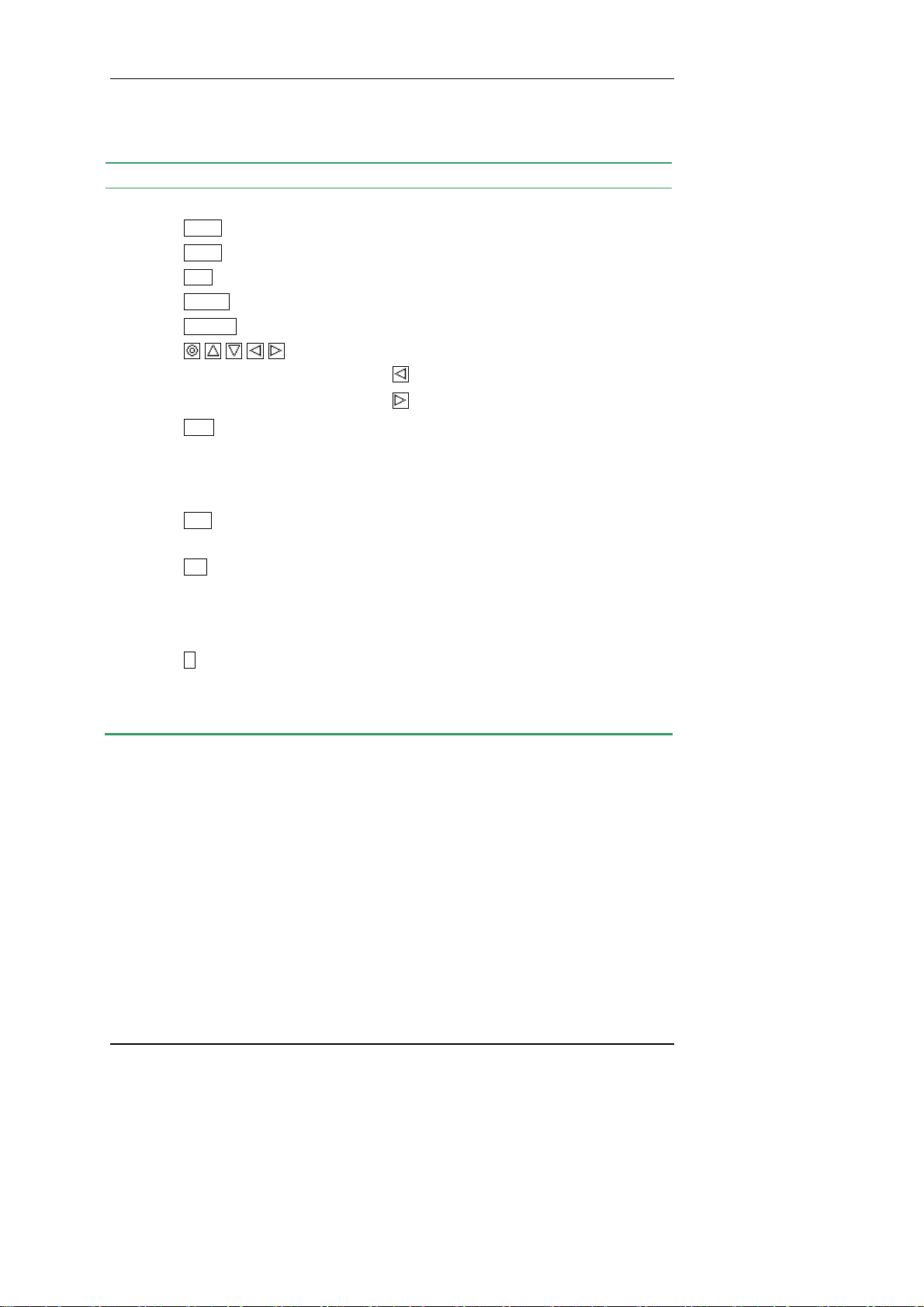
Table 11
No. Key Names and functions
1
2
3
4
5
6
7
VolUp
VolDn
Lock
LeftSoft
RightSoft
Headphone jack
Volume Up: Increases the headphone/earpiece/ringer volume.
Volume Down: Decreases the headphone/earpiece/ringer volume.
Key lock
LeftSoft key
RightSoft key
Multi-function key: Enter/Up/Down/Left/Right
Standby Time
: Received Calls
Standby Time : Outgoing Calls
8
Clear
Clear
Text editing: Backspace
Text editing: Press and hold down to erase all the characters.
Viewing menu: Returns to previous screen
9
Send
Calling: Makes/answers a call
Press and hold down to redial the last number dialed.
10
End
End/Power off
During call: Cuts off the call.
Viewing menu: Menu erase
Press and hold down to switch the power On/Off
11
1
Number pad (0-9, *, #): Inputs numbers and letters for dialing
etc. Also used for menu shortcuts.
Standby *: Press and hold down to switch the courtesy mode.
Hitachi Cable 2/84
Page 6
User's Manual
1.2. Number pad input table
IP address input mode
Key Character assignments
1
1
2
2
3
3
4
4
5
5
6
6
7
7
8
8
9
9
. (dot)
*
0
0
#
Text input mode
Key Character assignments
1 / ,
1
2 a b c 2 A B C
2
3 d e f 3 D E F
3
4 g h i 4 G H I
4
5 j k l 5 J K L
5
6 m n o 6 M N O
6
7 p q r s 7 P Q R S
7
8 t u v 8 T U V
8
9 w x y z 9 W X Y Z
9
. * ! ? [ ] ^ _ ` { | } ~
*
0 @ space -
0
: # ; $ % & ‘ ( ) + < = >
#
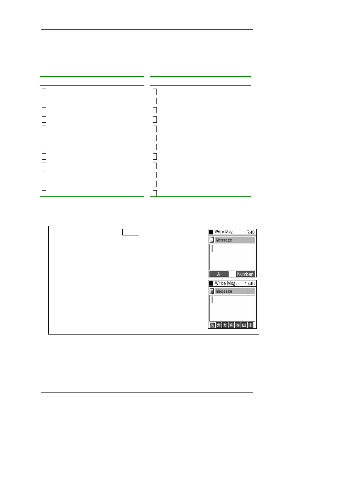
1.2.1 Text input mode
With the WirelessIP5000, you can use the number pad to input letters.
On the input screen, you use the LeftSoft key to switch the input mode
1
(uppercase/lowercase/special characters).
* The mode switching depends on the item being input.
Hitachi Cable 3/84
Page 7
User's Manual
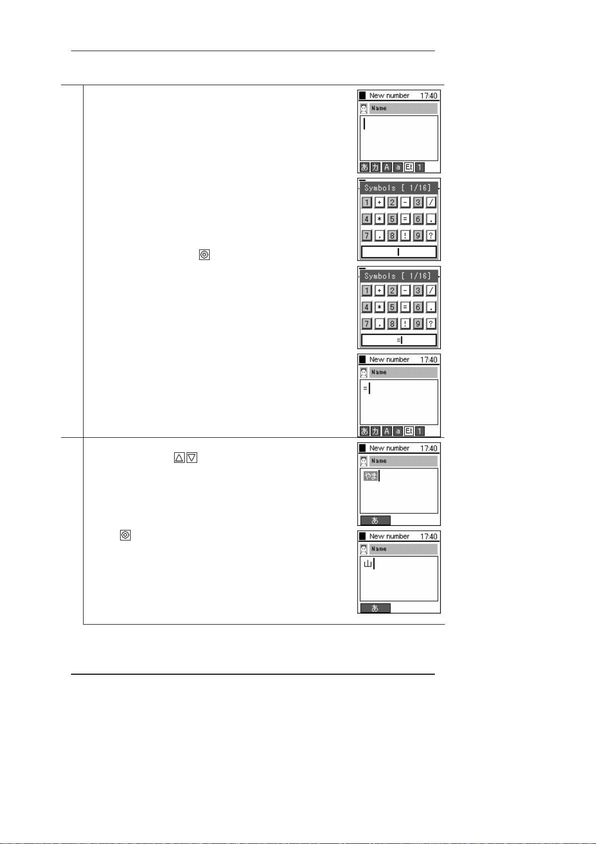
The type of symbol can be selected using the dial pad by selecting Code.
2
Select Code on the dial pad.
Define the Code by pressing the
When hiragana syllabic letters are selected, after input you can convert to
3
kanji ideograms with the
Press the
key to confirm the character.
key.
keys.
Hitachi Cable 4
Page 8

User's Manual
To delete the input character, press the Clear key.
4
Hitachi Cable 5
Page 9
User's Manual
2. Application
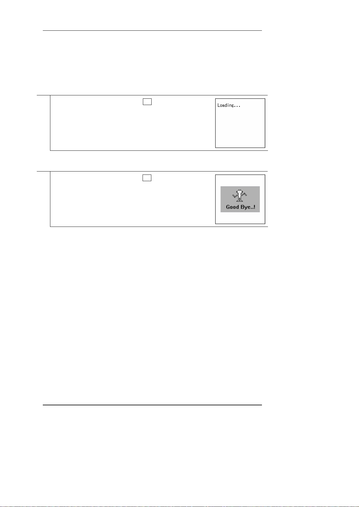
2.1. Power ON
Switching on the power for the phone
With the power Off, if you hold down the End key for at least 1 second, a
1
screen like that in the figure on the right is displayed and the power comes
On.
*The messages "Waiting…", "Loading…", and "Running…" are displayed
in order.
2.2. Power OFF
Switching off the power for the phone
With the power On, if you hold down the End key for at least 1 second, a
1
screen like that in the figure on the right is displayed and the power goes
Off.
Note! After you switch off the power, you can not switch it back on again
for 3 seconds.
Hitachi Cable 6/84
Page 10
User's Manual
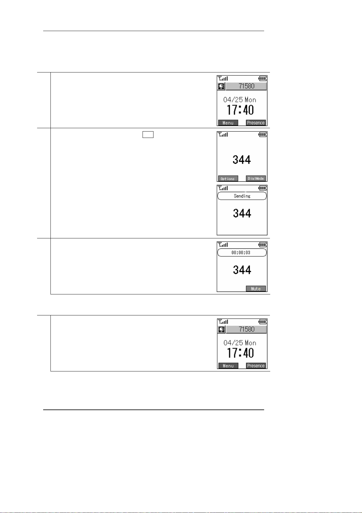
2.3. Call
Inputting the telephone number and making a call
If a set telephone number is displayed on the screen, you can receive a call.
1
Note! If the telephone number is not set correctly, "NotRegister" or
"Network Fail" is displayed.
Input the telephone number, then press the Send key.
2
If you succeed in placing the call, you can hear the ringtone at the other end.
When the other party answers, a screen like that in the figure on the right is
3
displayed, so during the call you can check the call duration.
2.4. Receive
Receiving a call.
If a set telephone number is displayed on the screen, you can receive a call.
1
Note! If the telephone number is not set correctly, "NotRegister" or
"Network Fail" is displayed.
Hitachi Cable 7/84
Page 11
User's Manual
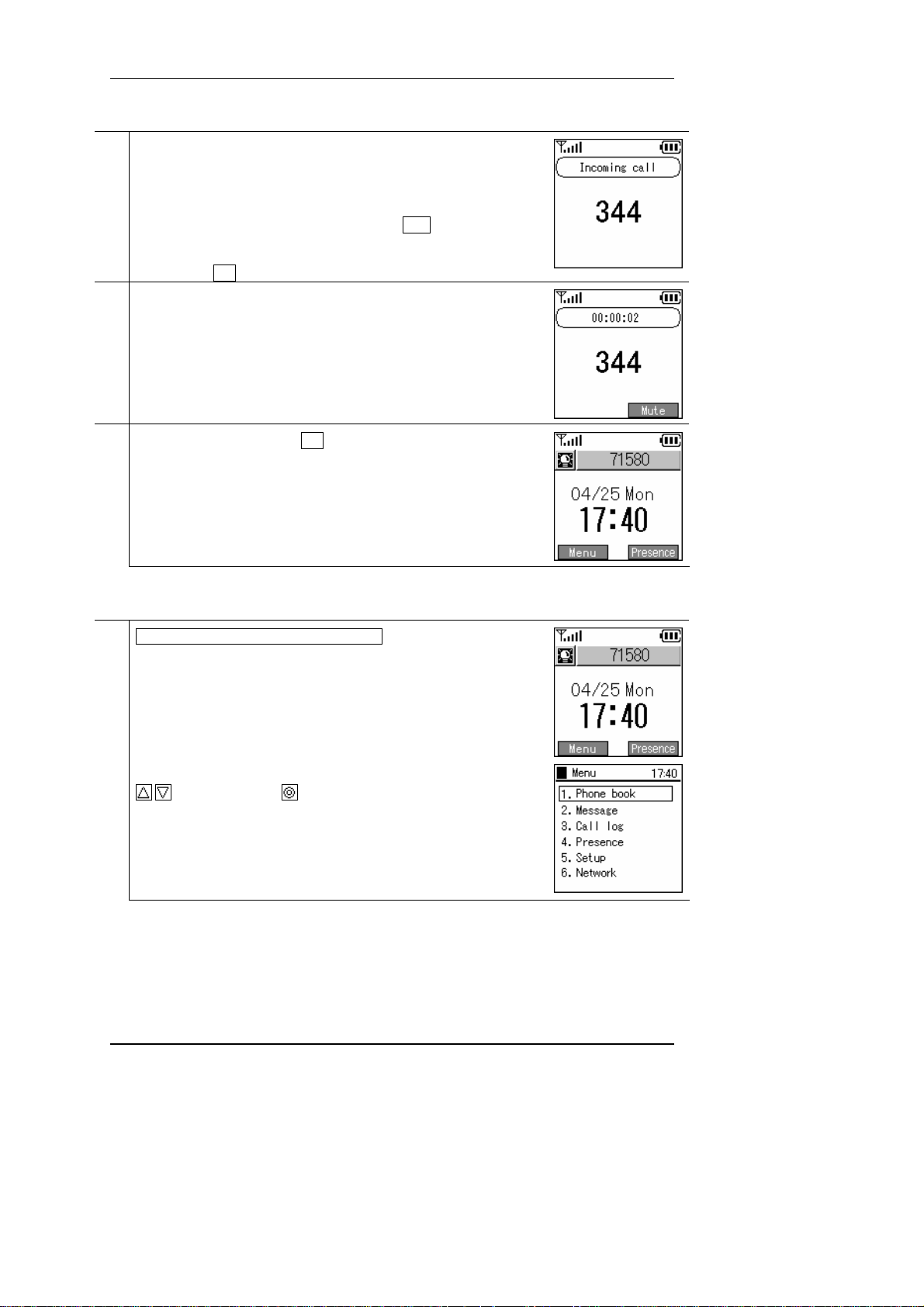
When a call comes in, the other party's telephone number is displayed on the
2
screen.
If their name is registered in the contacts list, their name is displayed above
the telephone number.
You can answer the incoming call by pressing the Send key.
* During call reception, "Receiving" is displayed on the screen.
* Pressing the End key during an incoming call ends that call.
When you answer an incoming call, a screen like that in the figure on the
3
right is displayed, so during the call you can check the call duration.
To cut off the power, press the End key.
4
When the call ends, a screen like that in the figure on the right is displayed.
2.5. Co ntact list
Searching, adding to, and editing the contact list
Press the LeftSoft key to select the menu item.
1
The screen in the figure on the right (second line) is displayed.
Either press the "1" on the number pad or select "1. Contact list" with the
keys, then press the key.
Hitachi Cable 8/84
Page 12
User's Manual
2.5.1 New registration
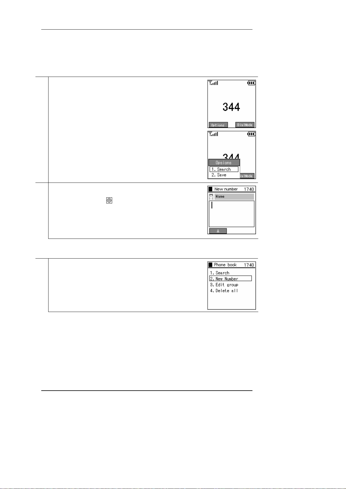
2.5.1.1 Registration from a telephone number
Inputting a telephone number to register it into the contact list
Input the telephone number, then press the LeftSoft key to select the sub-
1
menu and select "2. Save".
Please enter your information. Input the necessary information (name, kana
2
syllabic letters for name pronunciation, telephone number, group, speed
dialing number), then press
to save this information.
2.5.1.2 Registration from contact list menu
Registering information into the contact list from the new registration menu
From the contact list menu, select "2. New".
1
Hitachi Cable 9/84
Page 13
User's Manual
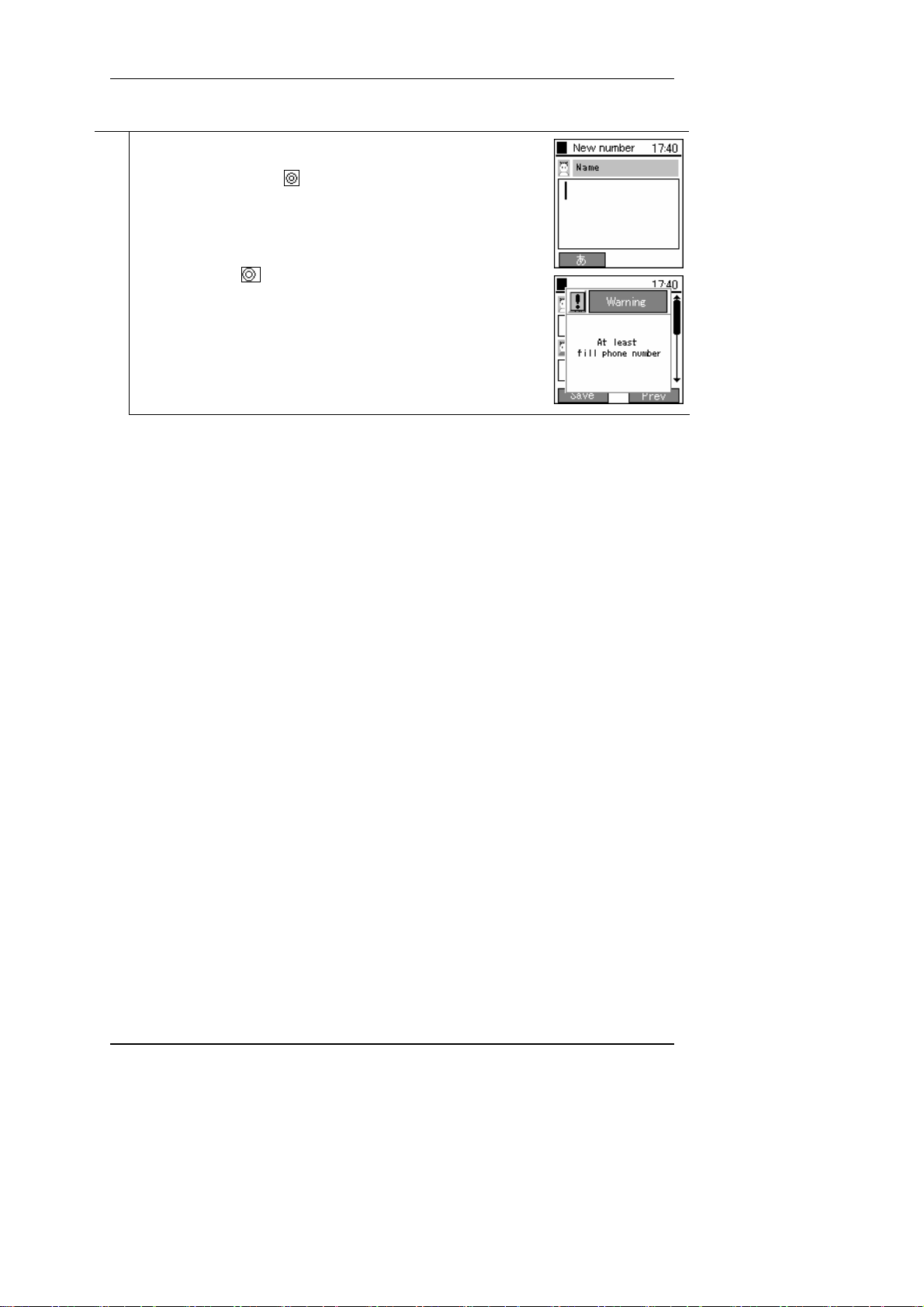
Please enter your information. Input the necessary information (name, kana
2
syllabic letters for name pronunciation, telephone number, group, speed
dialing number), then press
If you press the
<Warning> message in the figure on the right is displayed.
to save this information.
key without inputting a telephone number, the
Hitachi Cable 10/84
Page 14
User's Manual
2.5.1.3 Registration from search results
Registering details into the contact list from search results
Displaying the search results. (See the section on searches.)
1
Select the number you want to register, press the LeftSoft key to select the
sub-menu, and select "1. Add".
Hitachi Cable 11/84
Page 15

User's Manual
Input the information. Input the necessary information (name, kana syllabic
2
letters for name pronunciation, telephone number, group, speed dialing
number), then press
to save this information.
2.5.1.4 Registration from a call log
Registering details into the contact list from the call log.
Displays the call logs. (See the section on the call log.)
1
Select the number you want to register, press the LeftSoft key to select the
sub-menu, and select "1. Save".
Input the information. Input the necessary information (name, kana syllabic
2
letters for name pronunciation, telephone number, group, speed dialing
number), then press
Hitachi Cable 12/84
to save this information.
Page 16
User's Manual
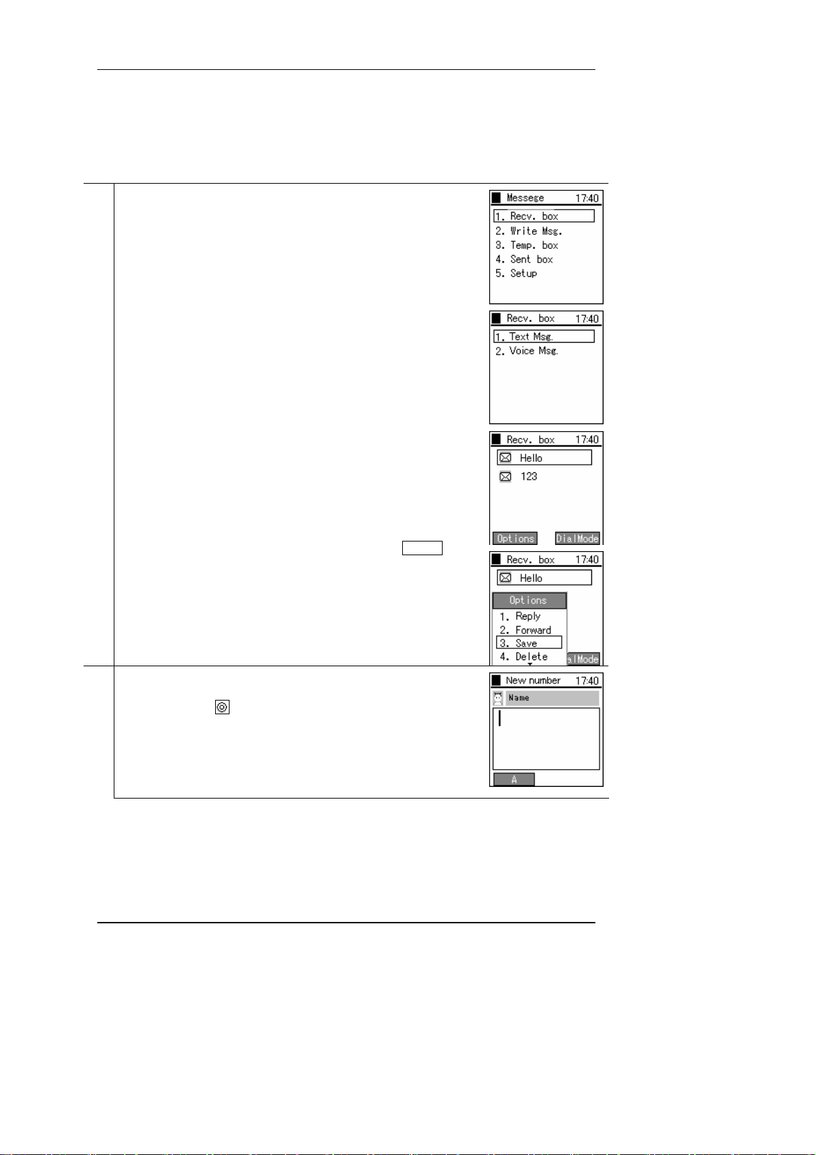
2.5.1.5 Registration from IM
Registering details into the contact list from the IM Inbox, drafts, or Outbox.
Display the IM menu. (See the section on IM.)
1
Select "1. Inbox".
Select "1. Text Message".
If there is a message, this will display as the diagram on the right.
After selecting the message to register from, press the LeftSoft key to
select the sub-menu, then select "3. Save".
Input the information. Input the necessary information (name, kana syllabic
2
letters for name pronunciation, telephone number, group, speed dialing
number), then press
Hitachi Cable 13/84
to save this information.
Page 17
User's Manual
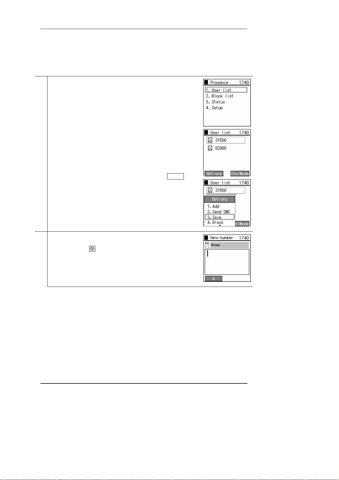
2.5.1.6 Registration from presence
Registering details into the contact list from the presence user list or block list.
Displays the presence menu. (See the section on presence.)
1
Select "1. User list" or "3. Block list".
If this has already been registered, this will display as follows.
After selecting the user you wish to register, press the LeftSoft key to
select the sub-menu, then select "3. Save".
Input the information. Input the necessary information (name, kana syllabic
2
letters for name pronunciation, telephone number, group, speed dialing
number), then press
Hitachi Cable 14/84
to save this information.
Page 18

User's Manual
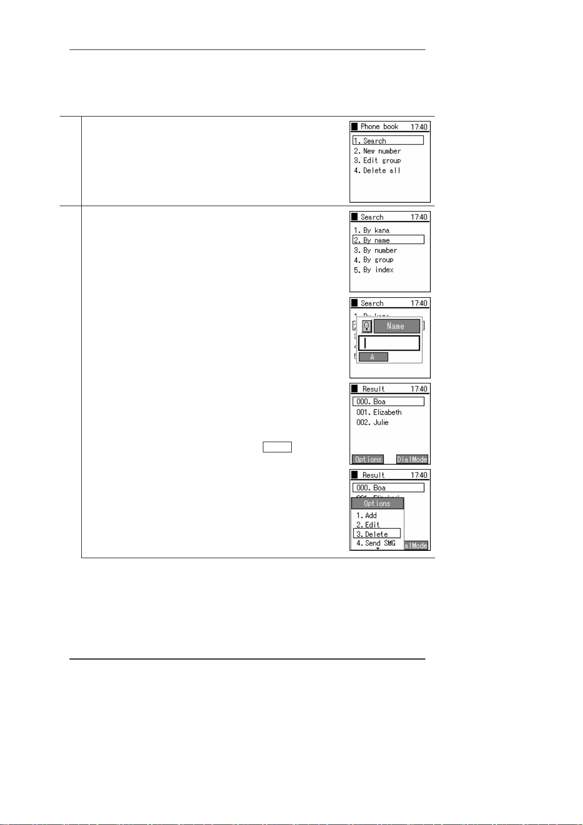
2.5.2 Call from contact list
Making a call from the contact list.
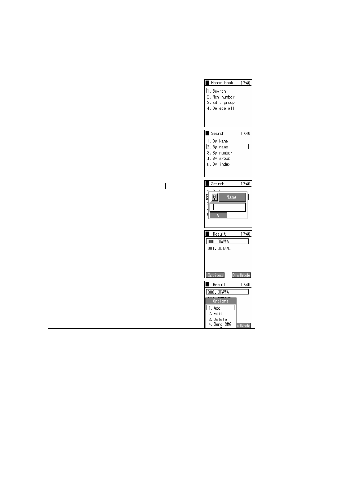
From the contact list menu, select "1. Search".
1
There are the following five methods for finding a telephone number.
2
(1) Pronunciation
(2) By name
(3) By telephone number
(4) By group
( 5) Abbreviated Numbers
The search results are displayed as in the figure on the right.
Note! You can search without inputting the entire search text.
Example: Suppose that the names "Ogawa" and "Ootani" are registered.
In this case, if you input "o", then press the
"Ootani" are displayed.
If you select a name then press the key, detailed information is
3
displayed.
Press the Send key or the key to make the call.
4
key, both "Ogawa" and
Hitachi Cable 15/84
Page 19
User's Manual
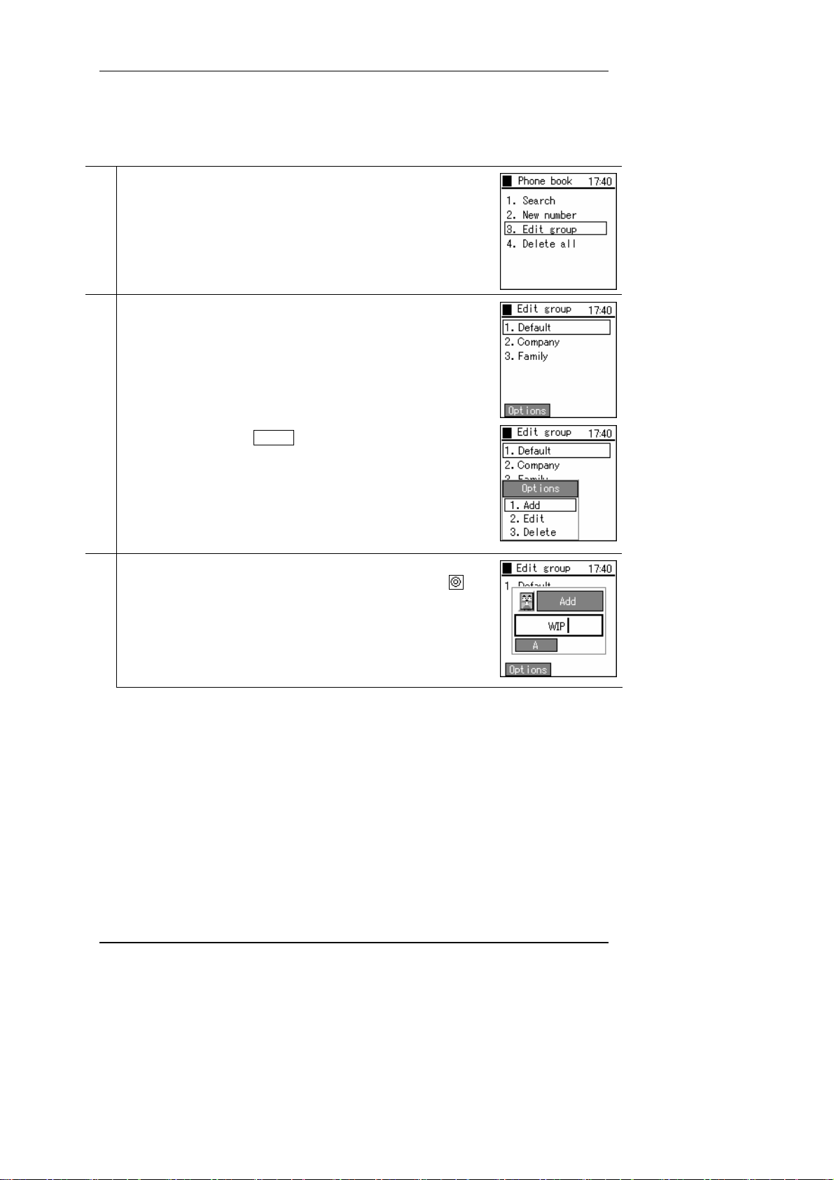
2.5.3 Group revision
Adding and deleting group names.
From the contact list menu, select "3 Revise group".
1
The“1.Default” is that groups can not be revised or erased.
2
You can create up to 10 groups.
To add a group, press the LeftSoft key to select the sub-menu, then select
"1. Add".
The figure on the right shows the addition of a group named "WIP". To save
3
the newly added group and return to the contact list menu, press the
key.
Hitachi Cable 16/84
Page 20
User's Manual
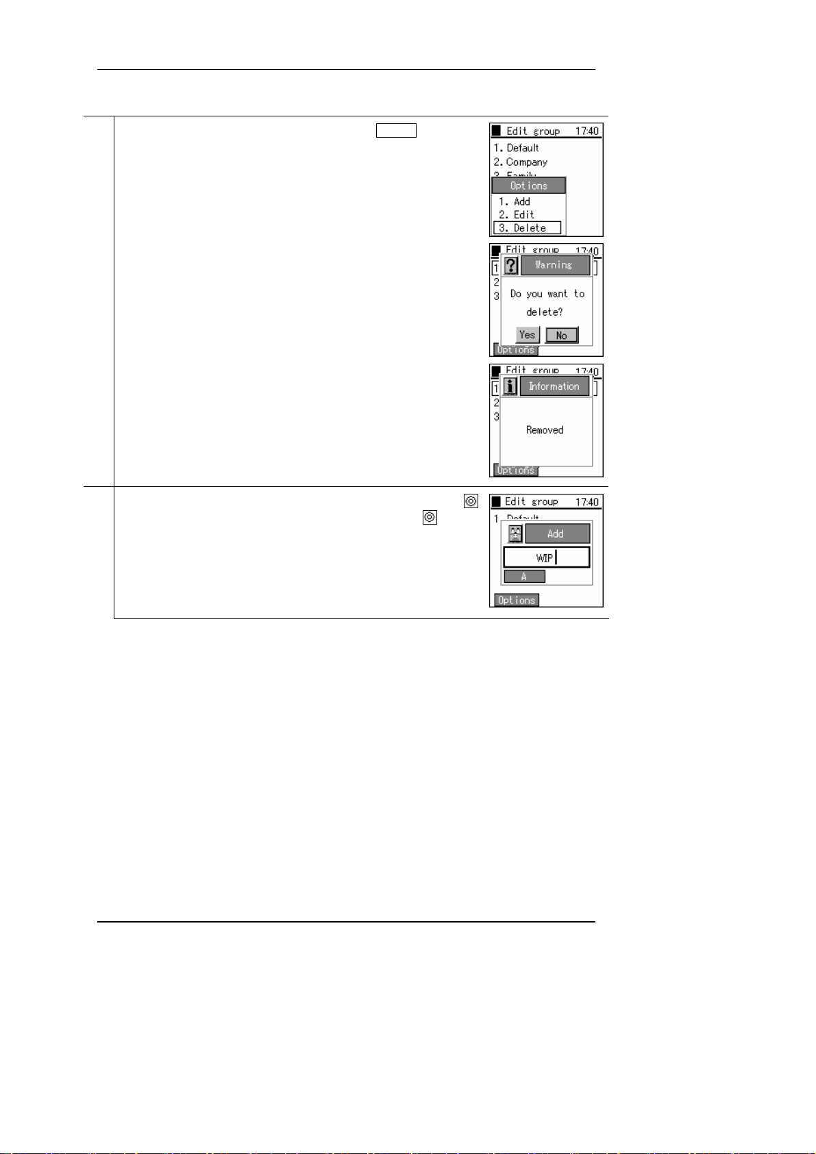
To delete a group, select the group to delete, press the LeftSoft key to select
4
the sub-menu, then select "3. Delete".
* After the deletion completion message is displayed, the display returns to
the contact list menu.
To change a group (name), select the group to change, then press the
5
key. Edit according to Step 3. After this, when you press the key and
save the new group name, the display returns to the contact list menu.
Hitachi Cable 17/84
Page 21
User's Manual
2.5.4 Erase one item from contact list
Deleting one data item from the contact list.
From the contact list menu, select "1. Search".
1
Search for the telephone number you want to delete. (See the section on
2
calling from the contact list.)
Select the telephone number to delete, then press the LeftSoft key to select
the sub-menu, then select "3. Delete".
Hitachi Cable 18/84
Page 22
User's Manual
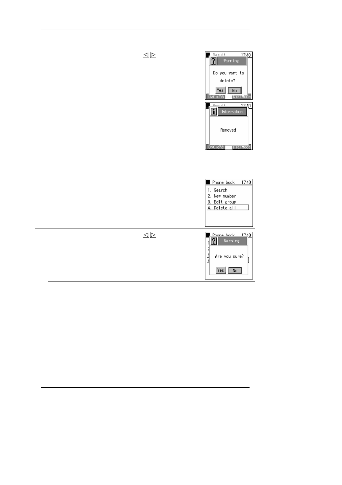
A confirmation message is displayed. With the keys select either
3
"Yes" or "No".
If you select "Yes", the "Deletion complete" message is displayed
immediately, then the display returns to the contact list menu.
2.5.5 Erase all
Deleting all the data in the contact list.
From the contact list menu, select "4. Delete all".
1
A confirmation message is displayed. With the keys select either
2
"Yes" or "No".
Hitachi Cable 19/84
Page 23
User's Manual
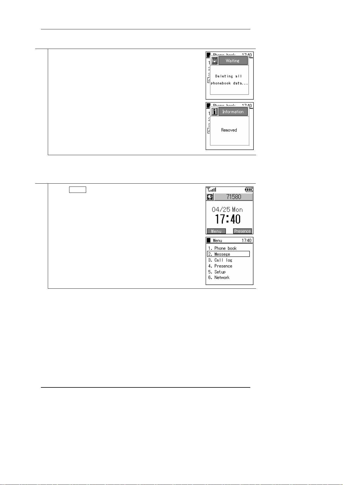
If you select "Yes", the process for deleting the entire contact list starts.
3
The "Deletion complete" message is displayed immediately, then the display
returns to the contact list menu.
2.6. IM
Displays the mail menu.
Press the LeftSoft key to select the menu item.
1
Select "2. IM".
* With some connection equipment, this is not possible.
Hitachi Cable 20/84
Page 24
User's Manual
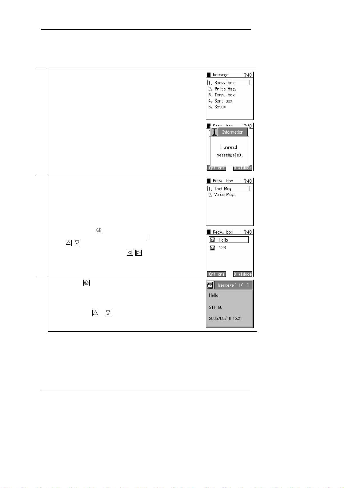
2.6.1 Inbox
Displays, edits, and deletes received messages.
From the IM menu, select "1. Inbox".
1
If there is an unread message, a screen is displayed showing the number of
unread messages.
After this screen goes out, when you select “1. Text Msg.” a list of the
2
unread messages is displayed.
If you do not press the
scrolls horizontally to display the entire message. Alternatively, you can
use the keys to select the next message up or down.
Enter key, the selected message automatically
To check a message manually, use the keys.
If you press the key with the message selected in Step 2, a screen like
3
that in the figure on the right is displayed.
If you do nothing with the display screen, the message is automatically
scrolled vertically.
You can also use the
* The screen contents include the date, telephone number, and message
contents.
Hitachi Cable 21/84
or key to check a message manually.
Page 25

User's Manual
To reply to a received message, select that message, press the LeftSoft key
4
to select the sub-menu, then select "1. Reply".
Input the message with the number keys and the LeftSoft key.
Input the telephone number to send to.
By pressing the
right is displayed.
Hitachi Cable 22/84
key, a confirmation screen like that in the figure on the
Page 26
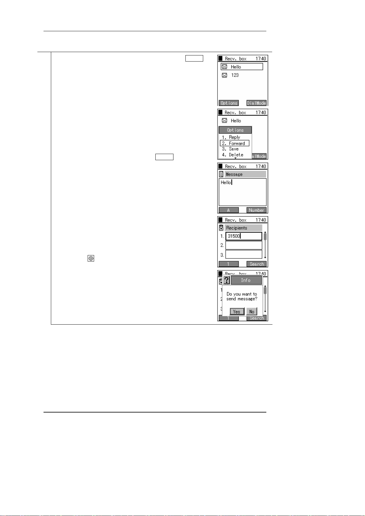
User's Manual
To forward a received message, select that message, press the LeftSoft key
5
to select the sub-menu, then select "2. Forward".
Input the message with the number keys and the LeftSoft key.
Input the telephone number to send to.
By pressing the
right is displayed.
Hitachi Cable 23/84
key, a confirmation screen like that in the figure on the
Page 27
User's Manual
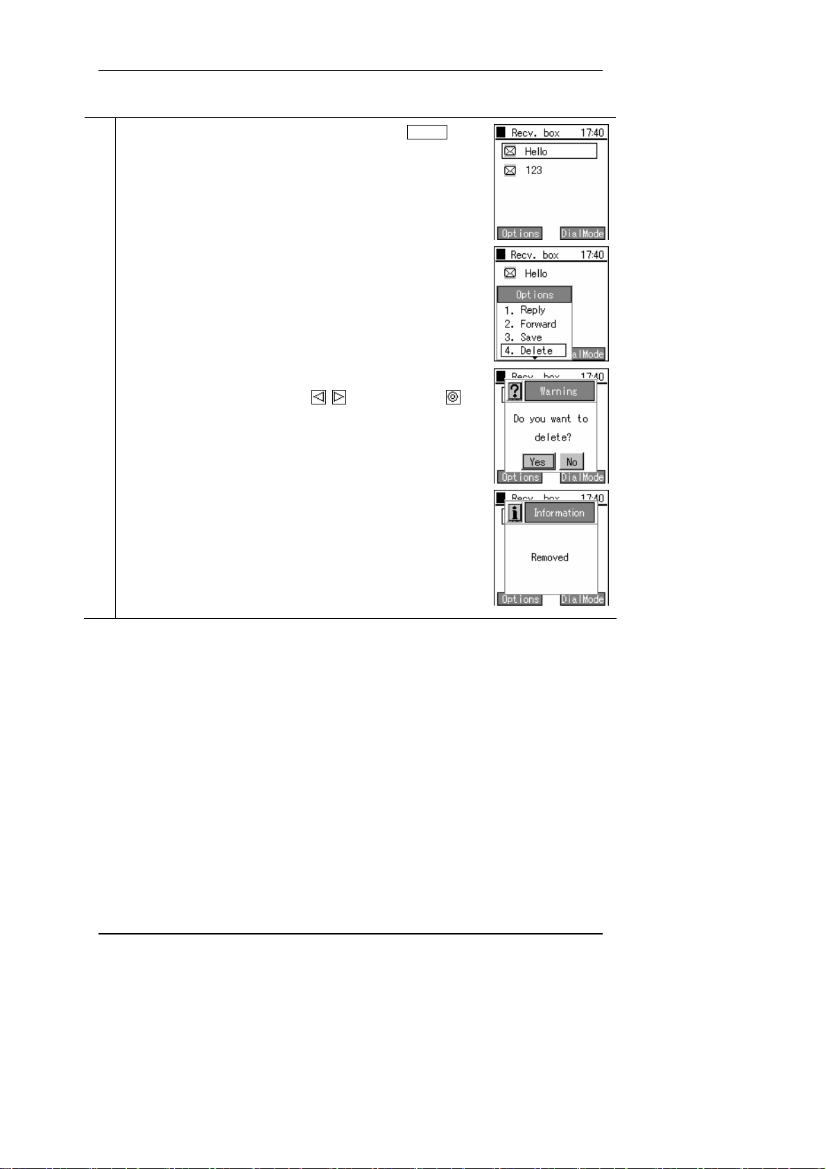
To delete a message, select the message to delete, press the LeftSoft key to
6
select the sub-menu, then select "4. Delete".
The screen in the figure on the right (3rd line) is displayed.
Select whether or not to delete with the
to finalize the deletion.
keys, then press the key
Hitachi Cable 24/84
Page 28

User's Manual
To delete all the messages in the Inbox, press the LeftSoft key to select the
7
sub-menu, then select "5. Delete All".
Hitachi Cable 25/84
Page 29

User's Manual
2.6.2 New Message
Writing and sending a new message.
From the IM menu, select "2. New Message".
1
Input the message with the number keys and the LeftSoft key.
2
Input the telephone number to send to.
Hitachi Cable 26/84
Page 30

User's Manual
The message is sent with the RightSoft key in the message input column.
3
A screen similar to that on the right will be displayed, please select “Yes”.
The processing during sending is displayed as in the figure on the right.
A “Send Completed” message screen immediately displays.
Hitachi Cable 27/84
Page 31

User's Manual
2.6.3 Drafts
An unsent message is stored temporarily.
From the IM menu, select "3. Draft".
1
If you are not sending the message right away, to save it for later use, press
2
the End key.
To save the message, select "Yes" with the
key.
keys, then press the
If you do not press the key, the selected message is automatically
3
scrolled horizontally to display the entire message. Alternatively, you can
use the
To check a message manually, use the keys.
keys to select the next message up or down.
Hitachi Cable 28/84
Page 32

User's Manual
If you press the key with the message selected in Step 3, a screen like
4
that in the figure on the right is displayed.
If you do nothing with the display screen, the message is automatically
scrolled vertically.
You can also use the
* The screen contents include the date, telephone number, and message
contents.
To edit a "draft" message, select that message, press the LeftSoft key to
5
select the sub-menu, then select "1. Edit".
The screen becomes as in the figure on the right, so with the
move to the input column you want to edit and edit it.
or key to check a message manually.
keys,
Hitachi Cable 29/84
Page 33

User's Manual
To delete a "draft", press the LeftSoft key to select the sub-menu, then
6
select "2. Delete".
The screen in the figure on the right (3rd line) is displayed.
Select whether or not to delete with the
to finalize the deletion.
keys, then press the key
Hitachi Cable 30/84
Page 34

User's Manual
To delete a "draft", press the LeftSoft key to select the sub-menu, then
7
select "3. Delete All".
The screen in the figure on the right (3rd line) is displayed.
Select whether or not to delete with the
to finalize the deletion.
keys, then press the key
Hitachi Cable 31/84
Page 35

User's Manual
2.6.4 Outbox
Displaying, editing, deleting, and re-sending of sent messages
From the IM menu, select "4. Send Box".
1
Alternatively, you can use the keys to select the next message up or
2
down. The selected message is automatically scrolled horizontally to display
the entire message.
To check a message manually, use the
When you select the message and press the key, a screen like that in the
3
figure on the right is displayed.
You can also use the
* The screen contents include the date, telephone number, and message
contents.
or key to check a message manually.
keys.
Hitachi Cable 32/84
Page 36

User's Manual
To edit a send message, select that message, press the LeftSoft key to select
4
the sub-menu, then select "1. Edit".
The screen becomes as in the figure on the right, so with the
move to the input column you want to edit and edit it.
keys,
Hitachi Cable 33/84
Page 37

User's Manual
To delete a send message, select that message, press the LeftSoft key to
5
select the sub-menu, then select "2. Delete".
The screen in the figure on the right (3rd line) is displayed.
Select whether or not to delete with the
to finalize the deletion.
keys, then press the key
Hitachi Cable 34/84
Page 38

User's Manual
To delete a send message, select that message, press the LeftSoft key to
6
select the sub-menu, then select "3. Delete All".
The screen in the figure on the right (3rd line) is displayed.
Select whether or not to delete with the
finalize the deletion.
keys, then press the key to
Hitachi Cable 35/84
Page 39

User's Manual
2.6.5 Setting
Configure Ringtone Mode
From the IM menu, select "5. Settings".
1
Displays configuration information.
2
Configuration Information: Displays ringtone mode.
Hitachi Cable 36/84
Page 40

User's Manual
2.7. Call log
Displays the outgoing call log and the incoming call log.
Press the LeftSoft key and select the menu item.
1
A screen like that in the figure on the right is displayed.
Either press the "3" on the number pad or select "3. Call logs", then press
the
key.
* When on standby, you can also display the incoming call log with the
key and the outgoing call log with the key.
The call log menu has the "Incoming call log", "Outgoing call log", and
2
"Delete all data" items.
Either press the "1" on the number pad or select "1. Received Calls", then
press the
The incoming call list is displayed. If a name is set for a telephone number,
that is displayed. If not, the telephone number is displayed.
* The date and time the call came in are displayed above the
name/telephone number.
Incoming call log
Missed call log
key.
Hitachi Cable 37/84
Page 41

User's Manual
Select "2.Outgoing call log".
3
The name or telephone number called is displayed in the same way as for
the incoming call log.
* The date and time the call was made are displayed above the
name/telephone number.
Outgoing call log
2.7.1 Details
Displays detailed call log information.
When you press the key on the name/telephone number that you want
1
more detailed information about, a pop-up window like that on the right is
displayed. You can check information by moving up and down with the △
▽ keys.
Information content: Name, telephone number, group, index, call time
2.7.2 Call log delete
Deleting one call from a call log.
Displays the call logs.
1
To delete a call log, select the call log to delete, press the LeftSoft key to
select the sub-menu, then select "2. Delete".
Hitachi Cable 38/84
Page 42

User's Manual
The screen in the figure on the right is displayed.
2
Select whether or not to delete with the
to finalize the deletion.
keys, then press the key
2.7.3 Delete all data
Deleting the entire call logs.
Select "3.Delete all data".
1
Hitachi Cable 39/84
Page 43

User's Manual
The screen in the figure on the right is displayed.
2
Select whether or not to delete with the
to finalize the deletion.
keys, then press the key
2.7.4 Calling from the call log
Making a call from a call log.
With a call log displayed, you can make a call by pressing the Send key
1
with the name/telephone number highlighted.
If their name is registered in the contacts list, their name is displayed above
the telephone number.
Hitachi Cable 40/84
Page 44

User's Manual
2.8. Presence
Displays the presence menu.
Press the LeftSoft key to select the menu.
1
* With some connection equipment, this is not possible.
A screen like that in the figure on the right (second row) is displayed.
Either press the "4" on the number pad or select "4. Presence", then press
the
key.
2.8.1 User list
Displaying a list of registered users.
To look at a list of registered users, either press the "1" on the number pad
1
or select "1.User list", then press the
A list of the registered users is displayed.
2
To add or delete a registered user, press the LeftSoft key to select the submenu, then select either "1. Register User" or "5. Delete".
key.
Hitachi Cable 41/84
Page 45

User's Manual
To register a user, select the number to register, press the LeftSoft key to
3
select the sub-menu, and select "1. Register User".
Use the number pad and the LeftSoft key to enter the user's telephone
number.
If you try to input an Alias that is already registered, the "Already
Registered" message is displayed and the display returns to the input field.
Hitachi Cable 42/84
Page 46

User's Manual
To send a message to a registered user, select the message to send and press
4
the LeftSoft key to select the sub-menu, then select "2. IM Send".
To register a registered user to a block list, selecting the message to register,
5
press the LeftSoft key to select the sub-menu, then select "4. Register Block
".
Hitachi Cable 43/84
Page 47

User's Manual
To delete a registered user, select the registered user to delete, press the
6
LeftSoft key to select the sub-menu, then select "5. Delete".
The screen in the figure on the right (3rd line) is displayed.
Select whether or not to delete with the
to finalize the deletion.
keys, then press the key
Hitachi Cable 44/84
Page 48

User's Manual
To delete all registered users, press the LeftSoft key to select the sub-menu,
7
then select “6. Delete All”.
The screen in the figure on the right (3rd line) is displayed.
Select whether or not to delete with the
to finalize the deletion.
keys, then press the key
2.8.2 Block list
Displaying a list of users registered in the block list. Your status is not disclosed to users registered in the
block list.
To look at a list of registered users, either press the "3" on the number pad
1
or select "2. Block List", then press the
key.
Hitachi Cable 45/84
Page 49

User's Manual
A list of the registered users is displayed.
2
To register a block list, select the user to register, press the LeftSoft key to
3
select the sub-menu, then select “1. Block Register”.
Hitachi Cable 46/84
Page 50

User's Manual
To send a message to a registered user, select the registered user to send the
4
message to, press the LeftSoft key to select the sub-menu, then select "2. IM
Send".
To delete a block of registered users, select the registered user to delete,
5
press the LeftSoft key to select the sub-menu, then select "4. Unblock".
Hitachi Cable 47/84
Page 51

User's Manual
To delete a registered user, select the registered user to delete, press the
6
LeftSoft key to select the sub-menu, then select "5. Delete".
The screen in the figure on the right (3rd line) is displayed.
Select whether or not to delete with the
to finalize the deletion.
keys, then press the key
Hitachi Cable 48/84
Page 52

User's Manual
To delete all registered users, press the LeftSoft key to select the sub-menu,
7
then select “6. Delete All”.
The screen in the figure on the right (3rd line) is displayed.
Select whether or not to delete with the
to finalize the deletion.
keys, then press the key
2.8.3 Status
Changing your own status.
To look at a status list, either press the "3" on the number pad or select "3.
1
Status", then press the
key.
Hitachi Cable 49/84
Page 53

User's Manual
You can set the status by using the keys, then pressing the key.
2
There are seven status modes.
: Online
: Briefly away from seat
: Away from seat
: Offline
2.8.4 Setting
From the Presence menu, select “4. Settings”.
1
Displays configuration information.
2
Hitachi Cable 50/84
Page 54

User's Manual
2.9. Basic settings menu
Displays the setting menu.
Press the LeftSoft key to select the menu item.
1
A screen like that in the figure on the right (second row) is displayed.
Select "5.Setting".
2.9.1 Sound/Vibration
Setting the ringer/vibration type.
You can switch the ringtone/ mode/ LED for inside lines and outside lines.
1
From the setting menu, select "1. Sounds/ Vibration".
Hitachi Cable 51/84
Page 55

User's Manual
You can switch the ringtone/ mode/ LED for inside lines and outside lines.
2
To set the ringer for a call coming in on an outside line, either press the "1"
on the number pad or select "1. External 1", then press the
To set the ringer for a call coming in on an inside line, either press the "3"
on the number pad or select "3. Internal 1", then press the
There are four settings available, two each for inside and outside lines.
Example
Setting Ringer Mode LED
External 1 Bell 1 Bell Blue
External 2 Bell 5 Vibration Red
Internal 1 Bell 11 Bell + vibration No
Internal 2 Bell 13 Mute Blue
* Depending on the device connected, this is not possible. In this case, only
"1. External 1" is enabled.
Displays configuration information. (Ringtone, Mode, LED)
3
There are four modes.
・ Bell (bell)
・ Vibration (vibration)
・ Bell + vibration (bell + vibration)
・ Silent (mute)
There are three LED colors.
・ RED
・ BLUE
・ (None)
key.
key.
alert
Hitachi Cable 52/84
Page 56

User's Manual
2.9.2 Phone Lock
From the settings menu, select "2. Phone Lock".
1
Select "1. KeyLock password".
2
* Do the same for the "Admin password".
When you select "1. KeyLock password", the system asks you for the
3
current password. Please enter the correct password.
When you input the correct password, the system asks you to input the new
4
password.
Hitachi Cable 53/84
Page 57

User's Manual
For verification, the system asks you to input the new password a second
5
time.
When you input the password, a screen like that on the right is displayed for
a few seconds.
Select “2. Lock Mode”.
6
Select either “Password” or “No Password” with the
2.9.3 Alarm
From the settings menu, select "3. Alarm".
1
keys.
Hitachi Cable 54/84
Page 58

User's Manual
Select either “1. Alarm”, “2. Alarm”, or “3. Alarm”.
2
Displays configuration information. (Settings, Time, Bell, No. of Times)
3
2.9.4 Volume
Adjusting the volume of WirelessIP5000.
From the settings menu, select "4. Volume".
1
Displays configuration information. (Ringtone Volume, Headset Volume,
2
Call Volume, Notify Volume)
Adjust the volume with the keys.
Hitachi Cable 55/84
Page 59

User's Manual
2.9.5 Error Lamp
From the setting menu, select “5. Error Notify”.
1
Select “1. Service Lamp”.
2
Displays configuration information. (Use Lamp, Mode, Interval)
3
Hitachi Cable 56/84
Page 60

User's Manual
Select “2. Error Msg.”.
4
Select “On” or “Off” with the
keys
2.9.6 Information display
From the setting menu, select "6. Information Display".
1
From the information display menu, select "1. TCP/IP".
2
Network Information displays: Use DHCP, IP address, Netmask, Gateway,
DNS1, and DNS2.
Hitachi Cable 57/84
Page 61

User's Manual
From the information display menu, select "2. Wireless LAN".
3
Wireless LAN Information displays: Current Network, SSID, Signal (dBm),
Channel, WEP status, MAC address, Mode, and Beacon interval.
From the information display menu, select "3. SIP".
4
SIP Information displays: URL, User ID, Proxy, Registrar, and Outbound
Proxy.
From the information display menu, select "4. MAC Address".
5
The MAC address is displayed.
Hitachi Cable 58/84
Page 62

User's Manual
From the information display menu, select "5. WEB server".
6
Displays WEB server.
From the information display menu, select "6. Version".
7
Displays Software Version and Bootrom.
2.9.7 Advanced
From the information display menu, select "7. Advanced".
1
Hitachi Cable 59/84
Page 63

User's Manual
2.9.7.1 Time
From the Advanced menu, select "1. Clock".
1
From the Clock menu, select "1. Time Server".
2
Time Server Information displays: NTP, NTP Server 1 and NTP Server 2.
From the Clock menu, select "2. Time Offset".
3
Select time with the
Hitachi Cable 60/84
keys.
Page 64

User's Manual
From the Clock menu, select "3. Daylight Save".
4
Daylight save, Start date, Start time, End date, End time are displayed.
From the Clock menu, select "4. Display Format".
5
Displays Date Format and Time Format.
From the Clock menu, select "5. Date and Time Settings".
6
Displays Date and Time.
Hitachi Cable 61/84
Page 65

User's Manual
2.9.7.2 Brightness adjustment
From the Advanced menu, select "2. Adjust brightness".
1
Use the keys to adjust the contrast, then finalize with the key.
2
2.9.7.3 Font size
From the Advanced menu, select "3. Font size".
1
Using the keys to select the font size, then finalize with the key.
2
Hitachi Cable 62/84
Page 66

User's Manual
2.9.7.4 Language setting
Setting the language (Japanese/English).
From the setting menu, select "4. Language".
1
Use the keys to select either “Japanese” or “English”, then finalize
2
with the key.
2.9.7.5 Caller ID
From the Advanced menu, select "5. Calling number".
1
Use the keys to select either “Notify” or “Do Not Notify”, then
2
finalize with the key.
Hitachi Cable 63/84
Page 67

User's Manual
2.9.7.6 User Data Reset
From the Advanced menu, select "6. User Data Reset".
1
A confirmation message is displayed. Use the keys to select either
2
“Yes” or “No”.
Reference: The Admin menu is the menu for the network administrator. For details, refer to the
"WirelessIP 5000 Administrator Guide".
2.9.8 Courtesy mode On/Off
When courtesy mode is set, the ringer does not ring and all ringers go into vibration mode.
Press and hold down the * key on the number pad.
1
Hitachi Cable 64/84
Page 68

User's Manual
Silent mode and vibration mode are switched On.
2
To end courtesy mode, press and hold down the * key on the number pad
3
again.
Hitachi Cable 65/84
Page 69

User's Manual
2.9.9 KeyLock/ KeyUnlock
When the keylock is set, button operations are disabled.
Press and hold down the Lock key on the side of the phone.
1
Enter the password.
Note! The default value for the password is "0000". You can change the
password freely. (See the security section.)
The keylock comes On.
2
Hitachi Cable 66/84
Page 70

User's Manual
To unlock the keylock, press and hold down the Lock key on the side of the
3
phone again.
Enter the password.
2.10. Network
Press the LeftSoft key to select the menu.
1
* With some connection equipment, this is not possible.
Either press the "6" on the number pad or select "6. Network", then press
the
key.
Hitachi Cable 67/84
Page 71

User's Manual
2.10.1 Site Scan
Information on detected signals can be displayed.
Select “1. Site Scan” from the Network menu.
1
A message is displayed during the search.
2
The SSID for access points that where detected during the scan are
displayed. To see detailed information, select the SSID and press the
key.
Note!!!) At most 10 access points can be displayed.
To refresh the Site Scan Information, press the LeftSoft key to select the
3
sub-menu, then select "1. Refresh".
Site Scan reopens.
Hitachi Cable 68/84
Page 72

User's Manual
2.10.2 Ping Test
Select “2. Ping Test” from the Network menu.
1
2.10.2.1 Manual
Select “1. Manual” from the Ping Test menu.
1
2
2.10.2.2 1st Proxy
Select “2. 1st Proxy” from the Ping Test menu.
1
Hitachi Cable 69/84
Page 73

User's Manual
If the 1st Proxy is not configured, the message in the right diagram displays.
2
3
2.10.2.3 2nd Proxy
Select “3. 2nd Proxy” from the Ping Test menu.
1
If the 2nd Proxy is not configured, the message in the right diagram
2
displays.
3
Hitachi Cable 70/84
Page 74

User's Manual
2.10.2.4 Gateway
Select “4. Gateway” from the Ping Test menu.
1
2
2.10.2.5 TFTP server
Select “5. TFTP Server” from the Ping Test menu.
1
2
Hitachi Cable 71/84
Page 75

User's Manual
2.10.3 Network Reload
Select “3. Network Reload” from the Network menu.
1
Use the keys to select either “Reconnect” or “Disconnect”.
2
Hitachi Cable 72/84
Page 76

User's Manual
3. Various operation methods
3.1. Hold function
This is used to put a call on hold. The hold tone is played on the terminal that you have put on hold.
3.1.1 Hold
During a call, you can put the other party on hold by pressing the Send key.
Example: Putting B on hold
While A and B are talking, if A presses the Send key, B is put on hold.
Press the Send key.
At this time, the screens for A (the terminal that put the call on hold) and B (the terminal that was put on
hold) display as below and the hold tone is played on B (the terminal that was put on hold).
<Screen for the terminal
putting the call on hold>
A
Telephone number: Telephone number:
A
During call
Holding
B
<Screen for the terminal
put on hold>
B
Telephone number: 2310Telephone number: 2314
書式変更 : フォント : Times
New Roman, 10 pt
♪
書式変更 : フォント : Times
♪
New Roman, 10 pt
3.1.2 Hold release
During a hold, you can end the hold by pressing the Send key.
Hitachi Cable 73/84
Page 77

User's Manual
3.2. Calling method
3.2.1 Internal extension call
You can call an internal number by dialing the <extension number>, then pressing the Send key.
Check the inside number with the administrator.
Dial the inside number
(2222) for B, then press the
Send key.
A
Calling
B
Inside number: 1111
Base number: 10 Outside
line number:
05011111111
Prefix: 0
Inside number: 2222
Base number: 20 Outside
line number:
05011112222
Prefix: 0
3.2.2 Outside-line call
You can call an outside number by dialing the <prefix> + <outside telephone number>, then pressing the
Send key. Check the prefix and the outside number with the administrator.
Inside number: 1111
Base number: 10 Outside
line number:
05011111111
Prefix: 0
Dial B's prefix (0) and outside
number (05011112222), then press
the Send key.
Calling
A
Inside number: 2222
Base number: 20 Outside
line number:
05011112222
Prefix: 0
B
Hitachi Cable 74/84
Page 78

User's Manual
3.2.3 184/186 call
To temporarily switch caller ID On/Off, dial 184 or 186 before you dial the other party's telephone
number.
184 (Do not identify caller): Your telephone number is not identified.
186 (Identify caller): Your telephone number is identified.
<Examples of combination of caller ID On/Off>
System settings Dial input Caller ID display
Displayed No input Displayed
186 Displayed
184 No alert
No alert No input No alert
186 Displayed
184 No alert
Example: 184 call
Example: 186 call
Calling
A
Inside number: 1111
Base number: 10 Outside
line number:
05011111111
Prefix: 0
Calling
A
Inside
number: 1111
Base num
ber: 10 Outside
line
number:
05011111
111
Prefix: 0
B
Inside number: 2222
Base number: 20 Outside
line number:
05011112222
Prefix: 0
B
Inside number: 2222
Base number: 20 Outside
line number:
05011112222
Prefix: 0
Hitachi Cable 75/84
Page 79

User's Manual
3.2.4 Operation methods using call mode
You can make prefixed calls and 184/186 calls from the contact list, incoming call log, and outgoing call
log.
3.2.4.1 Calling in call mode from the contact list
When you select the telephone number from the contact list, press Right soft "Call mode", then on the
call mode screen press <1. Prefix 2.184 3.186>, then press the Enter key. The number you have input is
displayed with <0> attached and when you press Send, the outside call is made.
* Using the prefix + 184/186 gives the same results as the above operation.
3.2.4.2 Calling in call mode from the incoming call log or outgoing
call log
Displayed when the Enter key is pressed to the <Left <-> from the incoming call log display, or to the
<Right->> from the outgoing call log. Select a telephone number from a call log, then press Right soft
"Call mode", and then press <1. Prefix 2. 184 3. 186> on the call mode screen, then press the <Enter>
key. The input number is displayed with <0> attached, and when you press Send the outside call is made.
* Using the prefix + 184/186 gives the same results as the above operation.
3.2.5 Redial
You can redial the last telephone number dialed.
Press and hold down the Send key for at least 1 second.
1
The last telephone number dialed is redialed.
2
Hitachi Cable 76/84
Page 80

User's Manual
3.2.6 Speed dialing
You can make a call using its speed dialing number.
Input a speed dialing number registered in the contact list.
1
Press the last digit in the speed dialing number and hold it down for at least
2
1 second.
For example, for a speed dialing number of 001, hold down the "1" for at
least one second.
A call is made to the telephone number corresponding to the speed dialing
3
number input.
3.2.7 Timer between digits
If you input the telephone number with the Send key held down, the call is made automatically after the
telephone number is input.
Press the Send key.
1
Entering the telephone number.
2
Hitachi Cable 77/84
Page 81

User's Manual
After a short time, a call is made automatically to the telephone number that
3
corresponds to the speed dialing number entered.
Note! If call mode is used when inputting the telephone number, the timer
between digits does not operate.
Hitachi Cable 78/84
Page 82

User's Manual
4. Accessories
4.1. Accessory guidelines
These guidelines concern WirelessIP5000 accessories.
When unplugging the power cord for an accessory, hold it by the plug. Never pull the
cord itself
Keep accessories out of the reach of children.
Use only chargers, batteries, and accessories specifically manufactured for the Hitachi
Cable WirelessIP5000.Using a charger, battery, or accessory not designed for the
WirelessIP5000 would cause danger and would void the warranty for your telephone.
4.2. Accessories covered
Lithium ion battery
AC Adapter
Desktop charger
USB cable (option)
4.3. AC power supply adaptor
The AC Adapter displayed in Figure 2 can quick charge the customer’s WirelessIP5000.
When using the adaptor, plug the plug into a wall socket and connect the connector to the
base of the WirelessIP5000 or to the rear of the desktop charger.
You can charge the telephone while you are using it.
Figure 2
Hitachi Cable 79/84
Page 83

User's Manual
4.4. USB cable (option)
If you connect your WirelessIP5000 to a PC with the USB cable shown in Figure 3, you can
charge and change settings.
When setting the WirelessIP5000, check whether your WirelessIP5000 is directly connected
to your PC with the USB cable.
Figure 3
4.5. Installing the battery
Load the battery into the battery installation section at the rear of the WirelessIP5000, then
push in, in the direction of the release button until it clicks into place.
4.6. Removing the battery
While holding down the release button, pull the battery toward the bottom of the WirelessIP
5000 and remove it.
4.7. Charging with the desktop charger
Step 1: Plug the AC adaptor into a wall socket, then connect the connector to the rear of the
battery charger.
Step 2: As displayed in Figure 4, place the WirelessIP5000 into the top of the charger and push
until it clicks into place and the blue LED turns on.
Figure 4
Note: As Figure 5 shows, you can also charge with the optional USB cable instead of with the
AC adaptor.
Hitachi Cable 80/84
Page 84

User's Manual
Figure 5
4.8. Charging without the desktop charger
Step 1: Connect the AC adaptor to a wall socket.
Step 2: Remove the connector cover from the WirelessIP5000.
Step 3: Install the AC adaptor's 24-pin connector to the bottom of the WirelessIP5000.
Note: You can also charge with the optional USB cable instead of with the AC adaptor.
4.9. LED
LED color Status
Red
Blue
Operating, Call underway
Charging (Goes out when the charging is complete)
Table 1
Hitachi Cable 81/84
Page 85

User's Manual
5. Safety Instructions
This safety information applies to the WirelessIP5000 telephone. Please read the section below
before installing or using your WirelessIP5000.
5.1. Warning about emergency services
Since the WirelessIP5000 utilizes a communications network that is dependent on
commercial power supply, during a power failure it can not access emergency services. Use
some other means to access emergency services.
5.2. Warning about explosive gas
Do not use the WirelessIP5000 anywhere dangerous, such as in an area with explosive gas in
the air. Verify safety with qualified personnel before using a wireless device in such an
environment.
5.3. Warning about the impact of electromagnetic signals
Since the WirelessIP5000 uses wireless signals, there is a danger of it affecting nearby
electronic equipment. Do not use the WIRELESSIP5000 near medical equipment or anywhere
that use is prohibited.
5.4. Warning about battery handling
Do not dispose of the battery pack in fire or water. The battery could explode in a fire.
5.5. Battery safety items
Do not disassemble the battery pack, hit it, drill a hole in it, or incinerate it.
Failure to observe these precautions can result in fire, explosion, and injury. Do not touch
anything metal to the battery terminals.
Be particularly careful with any battery that is damaged or leaking. If you come in contact
with the battery fluid, wash that location well with plenty of soap and water. If any battery
fluid should get into your eyes, wash your eyes out with water for about 15 minutes and
seek medical attention.
Please do not charge in high temperature or high humidity environments.
If you will not be using the WirelessIP5000 for more than a month, please remove the
battery from the hadset and store it. Due to self-discharge the battery pack may become
unable to be used. Please store the battery at less than 20°C in a low-humidity environment
that is clean and free of dust.
When disposing of a used battery pack, consult a local waste processing contractor and
follow all laws concerning disposal and recycling.
To replace the battery, contact our Hitachi Cable sales store. Use a battery specifically
designed for the WirelessIP5000.
Use the AC adaptor manufactured specifically for the WirelessIP5000.
Hitachi Cable 82/84
Page 86

User's Manual
Appendix Specifications
No.
1 Physical
dimensions
2 Hardware
3 Wireless Radio
Item Specifications
Main Unit 44(W)mm×23(D)mm×127(H)mm
(Using lithium ion battery)
Lithium ion battery 43(W)mm×11(D)mm×68.5(H)mm
Small Battery *1 43(W)mm×9(D)mm×68.5(H)mm
Desktop charger 64(W)mm×89(D)mm×80(H)mm
Display
Button Number key pad (0-9, *, #), Send, End, Clear, Soft keys
Audio interface Microphone, speaker, 2.5-mm. stereo phone jack
Case material ABS, PC (Polycarbonate)
Other Vibration
Standards IEEE802.11b (11Mbps wireless LAN) (wi-fi)
Protocol CSMA/CA
Modulation DBPSK (1Mbps)
Communications technique DSSS (Direct Sequence Spread Spectrum)
Frequency band
Output power 10 mW/MHz max.
Communications distance
Data rate 1/2/5.5/11 Mbps
Number of pixels 128×128
8 lines, 10 columns (double-byte
characters)
Dot size 0.18(W)mm×0.22(H)mm
Dot pitch 0.19(W)mm×0.23(H)mm
Effective range 24.5(W)mm×29.5(H)mm
Field of vision range 28.5(W)mm×33.5(H)mm
Glass FSTN liquid crystal, 4-tone
Backlight White LED
Four-way key (up, down, left, right, Enter), Vol, keylock
DQPSK (2Mbps)
CCK (5.5&11Mbps)
2.4 ~ 2.497 GHz (14Ch)
Open space
*2
Indoors 30m (11Mbps)
160m (11Mbps)
200m (2Mbps)
40m (2Mbps)
Hitachi Cable 83/84
Page 87

User's Manual
Minimum reception
sensitivity
-84dBm@11Mbps(Typ.)
-88dBm@5.5Mbps(Typ.)
-89dBm@2Mbps(Typ.)
-93dBm@1Mbps(Typ.)
Handover Layer 2 *3
4 Software
(v.2.0.0)
Call control protocol SIP
Audio encoding G.711 A-Law/μ-Law 64kbps
G.729A 8kbps
Network settings DHCP (client operation only)/manual
NAT(Static), UPnP, STUN
Priority control DiffServ DSCP
Security SSID
WEP key 64/128/256 bits
802.1x (MD5, EAP-TLS,EAP-TTLS,EAP-PEAP)
Web Certification
Operational features NTP (client operation only)
Syslog (client operation only)
Transmission path
IP communications testing with Ping command
diagnostics function
Firmware upgrade TFTP (client operation only)
5 Battery
Lithium ion battery
Capacity 3.7V 1350mAH Li-ion
Call time About 3 hours 10 minutes *4
Standby time About 55 hours *4 *5
Battery charging time About 3 hours
Small Battery
*1
Capacity 3.7V 950mAH Li-ion
Call time About 2 hours 20 minutes *4
Standby time About 35 hours *4 *5
Battery charging time About 2 hours
*1 Small Battery sold separately
*2 The communications distance can vary with the weather, temperature, etc.
*3 L3 handover is also possible with the AP side specifications.
*4 The communication and standby times may decrease due to the settings of the environment conditions
and functions of the charge, temperature, and electromagnetic wave conditions
*5 Power save mode settings
Hitachi Cable 84/84
Page 88

Copyright© 2005
Hitachi Cable, LTD.
Otemachi Building, 6-1 Otemachi 1-chome,
Chiyoda-ku, Tokyo 100-8166, Japan
(First Edition, February 2005)
(Second Edition, July 2005)
 Loading...