

MODELS SV 8SA/SV 12SF
1. PRECAUTIONS IN DISASSEMBLY AND REASSEMBLY
Please pay particular attention to the following items during disassembly and reassembly.
Since the SV 8SA and the SV 12SF are of the same structure, explanation is given only on the Model SV 8SA.
[Bold]
The
numbers in the description correspond to the item numbers in the parts exploded diagram of the
SV 8SA and the numbers in
1-1. Disassembly
1-1-1. Remove the Felt Pad or the Pad [19] <19>
Remove the Felt Pad or the Pad
1-1-2. Remove the Base [18] <18>
Remove the Base
[18] <18>
Base
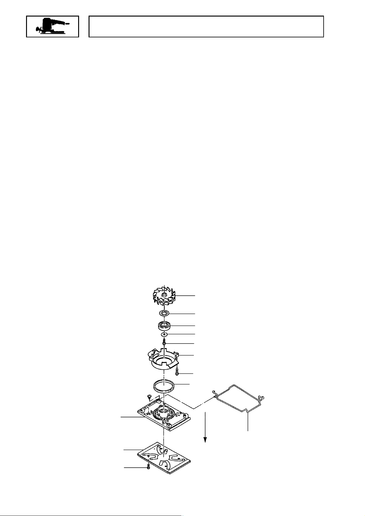
1-1-3. Remove the Fan Guide [34] <34>
Remove the Fan Guide
1-1-4. Remove the Thrust Washer [32] < 32> , t he Ball Bearing 6001 DDUCM [31] <31> , the Dust
Washer [30] <30> and the Balancer Fan [29] <29>
Remove the Thrust Washer
[30] <30>
and the Balancer Fan
[18] <18>
in the arrow-indicated direction.
<Bold>
together with the Paper Clips
[34] <34>
[32] <32>
to those in the parts exploded diagram of the SV 12SF.
[19] <19>
removing the two D4 x 20 Tapping Screws
[29] <29>
by removing the four M4 x 10 Machine Screws
, the Ball Bearing 6001 DDUCM
by removing the M4 x 12 Machine Screw
[37] <37>
and the Felt
[35] <35>
[31] <31>
[20] <20>
[36] <36>
, the Dust Washer
[33] <33>
by pulling out the
.
.
.
[18] <18>
[19] <19>
[20] <20>
[29] <29>
[30] <30>
[31] <31>
[32] <32>
[33] <33>
[34] <34>
[35] <35>
[36] <36>
Pull out
[37] <37>
Fig. 3
−
−#
1

1-1-5. Remove the Housing (B) [3] <3> and the Legs [16] <16>
After removing the Base
along the perforations with a cutter. Then remove the four Tapping Screws with D4 Flanges
<4>
securing the Housing (A)
Legs
[16] <16>
can be removed by pulling them out of the Housing (A)
[18] <18>
[12] <12>
and the Balancer Fan
and the Housing (B)
[29] <29>
[3] <3>
as indicated above, cut the Grip Tape
together, and the latter can be removed. The
[12] <12>
or the Housing (B)
1-1-6. Disassembly of the A rmature [28] <28>, the Stators [25] <25> and O t her Parts
(1) Remove the two Carbon Brushes
(A)
[12] <12>
.
[15] <15>
(2) Loosen the positive (+) terminal screw of the Slide Switch
and remove the lead wires of the Noise Suppressor
lead wires of the Stator
[25] <25>
.
(3) Loosen the negative (-) terminal screw of the Pillar Terminal
screwdriver and remove the lead wires of the Cord
[25] <25>
, and the parts inside the Housing can then be removed.
(4) With a bearing puller, pull of the two Ball Bearings 608 VVC2
Armature
[28] <28>
.
by lifting the Brush Holders
with a Phillips screwdriver
[5] <5>
[22] <22>
(excl. the U.S.A.) and Cord
[21] <21>
[10] <10>
and the lead wires of the Stator
[24] <24>
[14] <14>
off the Housing
with a flat-blade
press-fitted on both ends of the
[2] <2>
[10] <10>
[4]
[3] <3>
and the
.
1-2. Reassembly
Proceed as follows, paying particular attention to the it ems below.
1-2-1. Assembly of the Armature [28] <28> and the Stators [25] <25>
(1) With a hand press, press the two Ball Bearings 608VVC2
[24] <24>
until they hit against the stepped
portion of the Armature Shaft.
(2) Place the Stators
and make sure that the Armature
<12>
[25] <25>
and the Armature
[28] <28>
[28] <28>
in sequence within the Housing (A)
can turn freely.
1-2-2. Installing the Balancer Fan [29] <29> and the Dust Washer [30] <30>
When inserting the Balancer Fan
[29] <29>
observe the proper direction of the Dust Washer
into the Armature Shaft, bring their flat faces into alignment. Also
[30] <30>
. (See Fig.4.)
Armature Shaft flat portion
Bring this flat face into alignment
with that of the Armature Shaft.
[12]
[28] <28>
[24] <24>
Install this with the recessed side
facing the Balancer Fan
[29] <29>
[29] <29>
.
[30] <30>
Fig.4
−#2 −
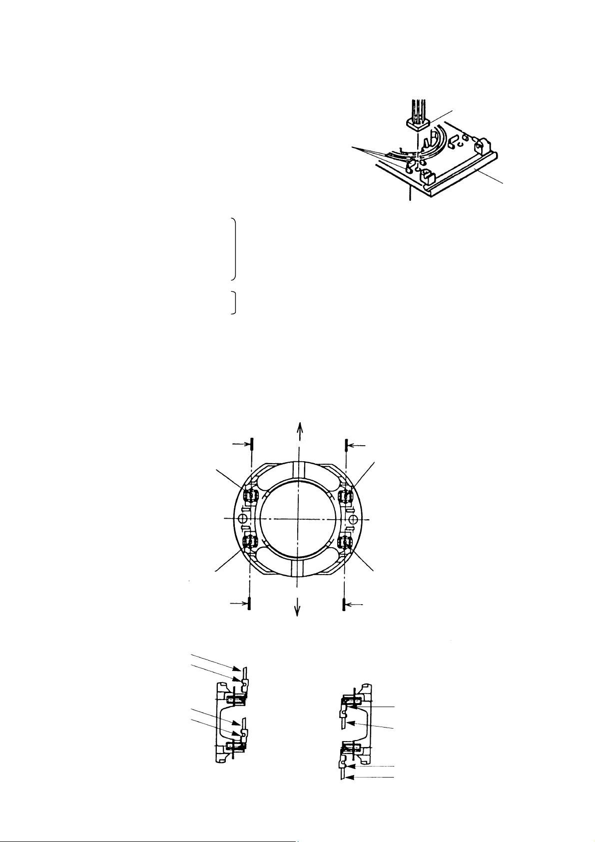
1-2-3. Installing the Base [18] <18>
Install the Legs
fitted within the Ribs. (See Fig.5.)
1-3. Screw Tightening Torque
D4 x 10 Tapping Screws with Flange
D4 x 16 Tapping Screws with Flange
D4 x 20 Tapping Screws with Flange
D4 x 20 Tapping Screws
M4 x 10 Machine Screws
M4 x 12 Machine Screw
Pillar Terminals with terminal screws......... 0.39 ± 0.1 N
Slide Switch with terminal screws .............. 0.39 ± 0.1 N
1-4. Wiring and Connecting Diagrams
[16] <16>
so that their lower parts are
1.96 ± 0.49 N
1.8 ± 0.4 N
Rib
⋅⋅⋅⋅
m (20 ± 5 kgf-cm)
⋅⋅⋅⋅
m (18 ± 4 kgf-cm)
⋅⋅⋅⋅
m (4 ± 1 kgf-cm)
⋅⋅⋅⋅
m (4 ± 1 kgf-cm)
Lower part
[18] <18>
Fig. 5
Perform the wiring as follows.
With the internal wire pointed at A, insert
the Tab Terminal (blue)
With the internal wire pointed at A, insert
the Internal Wire (brown)
Tab Terminal
Press the Tab Terminal
deeply into position.
[7] <7>
Fig. 6 Internal Wires Assembl y Positions (View from Commutator Side)
[7] <7>
.
[6] <6>
.
A
A-A
a
BA
With the internal wire pointed
at B, insert the Internal Wire
(blue)
[26] <26>
With the internal wire pointed
at B, insert the Tab Terminal
(brown)
[27] <27>
.
.
b
B
B-B
Internal Wire
Press the Tab Terminal
deeply into position.
[6] <6>
Fig. 7 Inserting Direction of I nt er nal Wires
−#3 −
Press the Tab Terminal
deeply into position.
Internal Wire
Press the Tab Terminal
deeply into position.
Tab Terminal
[26] <26>
[27] <27>

Wiring Diagram with Noise Suppressor
With Noise Suppressor
Cord
Noise Suppressor
[5] <5>
Tab Terminal (blue)
Pillar Terminal
[21] <21>
[10] <10>
[7] <7>
Brush Holders
Internal Wire
(brown)
[6] <6>
[14] <14>
Carbon Brushes
[15] <15>
Install with the terminal screw facing up.
Slide Switch
Internal Wire
(blue)
[26] <26>
Tab Terminal
(brown)
[22] <22>
[27] <27>
Without Noise Suppressor (for the U.S.A.)
Cord
[10] <10>
Tab Terminal (blue)
Pillar Terminal
[7] <7>
[21] <21>
Fig. 8
Internal Wire
(brown)
[6] <6>
Brush Holders
Carbon Brushes
[14] <14>
[15] <15>
Install with the terminal screw facing up.
Slide Switch
[22] <22>
Internal Wire (blue)
[26] <26>
Tab Terminal (brown)
[27] <27>
Fig. 9
−#4 −

Fit the lnternal Wire (brown)
[6] <6>
in this gap.
Fit the lnternal Wires (brown) (black) of the
Cord in this groove so that they do not
contact the Housing’s conductive part.
Internal Wire (black) of
Noise Suppressor
[5] <5>
Internal Wires (blue) (white)
of the Cord
Fit the Internal Wires (blue) (white)
of the Cord in this groove so that
they do not contact the Housing’s
air vents.
Fit the Internal Wires of the Noise
Suppressor
[5] <5> so
that they do
not contact the Housing’s air vents.
Fit the Internal Wire
of the Tab Terminal
(brown)
[27] <27>
Internal Wire (black)
of Noise Suppressor
[5] <5>
Internal Wires
(brown) (black)
of the Cord
(Cord, Noise Suppressor, Internal Wires, Tab Terminals)
Connecting Wiring Diagram
With Noise Suppressor
Internal Wire
(brown)
[6] <6>
Internal Wire (blue)
[26] <26>
Fig. 10 Wiring Diagram of the Internal Wires
Slide Switch
Tab Terminal (brown)
[27] <27>
12
Noise Suppressor
(excl. the U.S.A.)
[22] <22>
Brown
[5] <5>
Blue
Cord
Tab Terminal (blue)
Fig. 11
−#5 −
Pillar Terminal
[7] <7>
[21] <21>

Without Noise Suppressor (for the U.S.A.)
Tab Terminal (brown)
Internal Wire
(brown)
[6] <6>
Internal Wire (blue)
[26] <26>
[27] <27>
Tab Terminal (blue)
[7] <7>
Fig. 12
Slide Switch
12
Pillar Terminal
[22] <22>
Black
Cord
White
[21] <21>
1-5. Insulation Tests
On completion of disassembly and repair, measure the insulation resistance and conduct a dielectric
strength test.
Insulation Resistance: 7 MΩ or more with DC 500 V megohm tester
Dielectric:Strength: AC 4,000 V/1 min.
with no abnormalities 220 V - 240 V
(and for 110 V U.K. products)
AC 2,500 V/1 min.
with no abnormalities 110 V - 127 V
1-6. No-Load Current Value
After no-load operation for 30 minutes, the current value should be as follows.
Voltage 110 V 115 V 120 V 127 V 220 V 230 V 240 V
Current (A) Max. 1.15 A 1.10 A 1.05 A 0.99 A 0.57 A 0.55 A 0.53 A
−#6 −

2. STANDARD REPAIR TIME (UNIT) SCHEDULES
Variable
Model 10 20 30 40 50 60
Fixed
General
Assembly
Fixed Cost
Grip Tape
Felt Pad
Base
Paper Clip
Work Flow
Grip Tape
Felt Pad
Base
Paper Clip
0 min.
Fan Guide
Thrust Washer
Ball Bearing
(6001DDUCM)
Dust Washer
Balancer Fan
Slide Switch
Cord
Stator
Armature
Ball Bearing
(608VVC2)
x 2 pcs.
SV 8SA
SV 12SF
Cord 10 min.
Others
20 min.
Housing (A)
Housing (B)
Leg x 2 pcs.
Brush Holder
x 2 pcs.
CB x 2 pcs.
−#7 −
 Loading...