

Page 1

Random Orbit Sander
SV 13YA • SV 13YB
Handling instructions
Note:
Before using this Electric Power Tool, carefully read through these
HANDLING INSTRUCTIONS to ensure efficient, safe operation. It is
recommended that these INSTRUCTIONS be kept readily available
as an important reference when using this power tool.
Page 2

SYMBOLS
When symbols are used on the machine, refer to the followings to understand the meaning.
..................................................................
V
.................................................................
A
................................................................
Hz
................................................................
W
...............................................................
kW
..................................................................
g
................................................................
kg
volts
amperes
hertz
watts
kilowatts
grams
kilograms
GENERAL POWER TOOL SAFETY WARNINGS
WARNING
Read all safety warnings and all instructions.
Failure to follow the warnings and instructions may result in
electric shock, fire and/or serious injury.
Save all warnings and instructions for future reference.
The term “power tool” in the warnings refers to your mainsoperated (corded) power tool or battery-operated (cordless)
power tool.
1) Work area safety
a) Keep work area clean and well lit.
Cluttered or dark areas invite accidents.
b) Do not operate power tools in explosive atmospheres,
such as in the presence of flammable liquids, gases
or dust.
Power tools create sparks which may ignite the dust
or fumes.
c) Keep children and bystanders away while operating
a power tool.
Distractions can cause you to lose control.
2) Electrical safety
a) Power tool plugs must match the outlet.
Never modify the plug in any way.
Do not use any adapter plugs with earthed (grounded)
power tools.
Unmodified plugs and matching outlets will reduce
risk of electric shock.
b) Avoid body contact with earthed or grounded surfaces,
such as pipes, radiators, ranges and refrigerators.
There is an increased risk of electric shock if your
body is earthed or grounded.
c) Do not expose power tools to rain or wet conditions.
Water entering a power tool will increase the risk of
electric shock.
d) Do not abuse the cord. Never use the cord for carrying,
pulling or unplugging the power tool.
Keep cord away from heat, oil, sharp edges or moving
parts.
Damaged or entangled cords increase the risk of
electric shock.
e) When operating a power tool outdoors, use an
extension cord suitable for outdoor use.
Use of a cord suitable for outdoor use reduces the
risk of electric shock.
3) Personal safety
4) Power tool use and care
.............................................................
min
..................................................................
s
........................................................................................
n
0
.../min or ...min
or d.c.
or a.c.
-1
Revolutions or reciprocations per minute
.......
..................................................
..............................................
..............................................................
f) If operating a power tool in a damp location is
unavoidable, use a residual current device (RCD)
minutes
seconds
no-load speed
direct current
Alternating current
class ll tool
protected supply.
Use of an RCD reduces the risk of electric shock.
a) Stay alert, watch what you are doing and use common
sense when operating a power tool.
Do not use a power tool while you are tired or under
the influence of drugs, alcohol or medication.
A moment of inattention while operating power tools
may result in serious personal injury.
b) Use personal protective equipment. Always wear eye
protection.
Protective equipment such as dust mask, non-skid
safety shoes, hard hat, or hearing protection used for
appropriate conditions will reduce personal injuries.
c) Prevent unintentional starting. Ensure the switch is
in the off-position before connecting to power source
and/or battery pack, picking up or carrying the tool.
Carrying power tools with your finger on the switch
or energising power tools that have the switch on
invites accidents.
d) Remove any adjusting key or wrench before turning
the power tool on.
A wrench or a key left attached to a rotating part of
the power tool may result in personal injury.
e) Do not overreach. Keep proper footing and balance
at all times.
This enables better control of the power tool in
unexpected situations.
f) Dress properly. Do not wear loose clothing or
jewellery. Keep your hair, clothing and gloves away
from moving parts.
Loose clothes, jewellery or long hair can be caught
in moving parts.
g) If devices are provided for the connection of dust
extraction and collection facilities, ensure these are
connected and properly used.
Use of dust collection can reduce dust related hazards.
a) Do not force the power tool. Use the correct power
tool for your application.
The correct power tool will do the job better and safer
at the rate for which it was designed.
1
Page 3

b) Do not use the power tool if the switch does not
turn it on and off.
Any power tool that cannot be controlled with the
switch is dangerous and must be repaired.
c) Disconnect the plug from the power source and/or
the battery pack from the power tool before making
any adjustments, changing accessories, or storing
power tools.
Such preventive safety measures reduce the risk of
starting the power tool accidentally.
d) Store idle power tools out of the reach of children
and do not allow persons unfamiliar with the power
tool or these instructions to operate the power tool.
Power tools are dangerous in the hands of untrained
users.
e) Maintain power tools. Check for misalignment or
binding of moving parts, breakage of parts and any
other condition that may affect the power tool's
operation.
If damaged, have the power tool repaired before use.
Many accidents are caused by poorly maintained
power tools.
f) Keep cutting tools sharp and clean.
Properly maintained cutting tools with sharp cutting
edges are less likely to bind and are easier to control.
g) Use the power tool, accessories and tool bits etc. in
accordance with these instructions, taking into
account the working conditions and the work to be
performed.
Use of the power tool for operations different from
those intended could result in a hazardous situation.
5) Service
a) Have your power tool serviced by a qualified repair
person using only identical replacement parts.
This will ensure that the safety of the power tool is
maintained.
PRECAUTION
Keep children and infirm persons away.
When not in use, tools should be stored out of reach of children and
infirm persons.
SPECIFICATIONS
Model SV13YA SV13YB
Voltage (by areas)* (110 V, 120 V, 127 V, 220 V, 230 V, 240 V)
Power Input 230 W*
No-load speed 7000 – 12000 min
Sanding pad size (Outer diameter) 125 mm
Sanding paper size (Outer diameter) 125 mm
Weight (without cord) 1.4 kg
*Be sure to check the nameplate on product as it is subject to change by areas.
STANDARD ACCESSORIES
䡬 Sanding paper ............................................................ 1
䡬 Dust bag ...................................................................... 1
Standard accessories are subject to change without notice.
OPTIONAL ACCESSORIES (sold separately)
1. Sanding paper
Grain: AA40, AA60, AA80, AA120, AA180, AA240,
2. Polyester buff
Optional accessories are subject to change without notice.
AA320, AA400
PRIOR TO OPERATION
1. Power source
2. Power switch
3. Extension cord
APPLICATIONS
䡬 Roughing or finishing of woodwork and metal surfaces.
䡬 Preliminary sanding of woodwork and metal surfaces
before painting.
䡬 Paint removal.
䡬 Rust removal.
4. Installing the sanding paper
–1
Ensure that the power source to be utilized conforms
to the power requirements specified on the product
nameplate.
Ensure that the power switch is in the OFF positon. If
the plug is connected to a receptacle while the power
switch is in the ON position, the power tool will start
operating immediately, which could cause a serious
accident.
When the work area is removed from the power
source, use an extension cord of sufficient thickness
and rated capacity. The extension cord should be
kept as short as practicable.
Since the attachment is a hook-and-loop type, the
sanding paper can be installed easily by just pressing it onto the pad. When installing the sanding
paper, in order to match it to the holes in the pad,
gently fold it along the axis of two holes as shown
in Fig. 1.
Next, use the holes along the fold as a guide to
match the sanding paper and the pad. Finally, press
the entire sanding paper uniformly onto the pad.
12000 min
–1
2
Page 4
Sanding paper
Pad
Fig. 1
5. Attaching and Removing the Dust Bag
(1) Attaching the Dust Bag
As shown in Fig. 2, hold the dust gate and push it in
the direction of Arrow A to attach it to the dust outlet.
(2) Removing the Dust Bag
As shown in Fig. 2, hold the dust gate and pull it in
the direction of Arrow B to remove it from the dust
outlet.
A
CAUTION
Prior to the sanding operation, make sure the material
of surface you are going to sand.
If the surface under sanding operation is expected to
generate harmful / toxic dusts such as lead painted
surface, make sure the dust bag or appropriate dust
extraction system is connected with dust outlet tightly.
Wear the dust mask additionally, if available.
Do not inhale or touch the harmful / toxic dusts
generated in sanding operation, the dust can
endanger the health of yourself and bystanders.
6. Adjustment of speed (SV13YA only)
The SV13YA is equipped with the electric control
circuit which enables non-step speed control. To
adjust the speed, turn the dial shown in Fig. 3.
When the dial is set to “1”, the sander operates
at the minimum speed (7000 min
set to “6”, the sander operates at the maximum
speed (12000 min–1). Adjust the speed according to
–1
). When the dial
the material to be cut and working efficiency.
Dial
B
Dust bag
Dust gate
Dust outlet
Fig. 3
Fig. 2
By adjusting the dial, match the speed to the material and type of work.
Material
Rough grinding Fine grinding
Grain
Paintwork:
Sanding 180 400 3 – 6
Repairs
(scratches, rust spots) 120 240 2 – 4
Stripping 40 80 2 – 4
Wood:
Softwood 60 – 80 240 3 – 6
Hardwood 60 180 3 – 5
Veneers 240 320 2 – 4
Metals:
Aluminium 80 240 2 – 4
Steel 60 240 3 – 6
Stainless steel 120 240 3 – 6
Note: Please use this table as a standard.
7. RCD
The use of a residual current device with a rated
residual current of 30 mA or less at all times is
recommended.
3
Dial scale
Page 5

PRACTICAL OPERATING PROCEDURES
CAUTION
Never apply water or grinding fluid when sanding.
This could result in electrical shock.
1. Switching the sander ON and OFF
The power can be turned on by setting the lever to
ON (1) and turned off by setting the lever to OFF (0).
CAUTION
Never turn the power switch ON when the sander is
contacting the surface to be sanded. This is necessary
to preclude damage to the material. The same applies
when switching the power OFF.
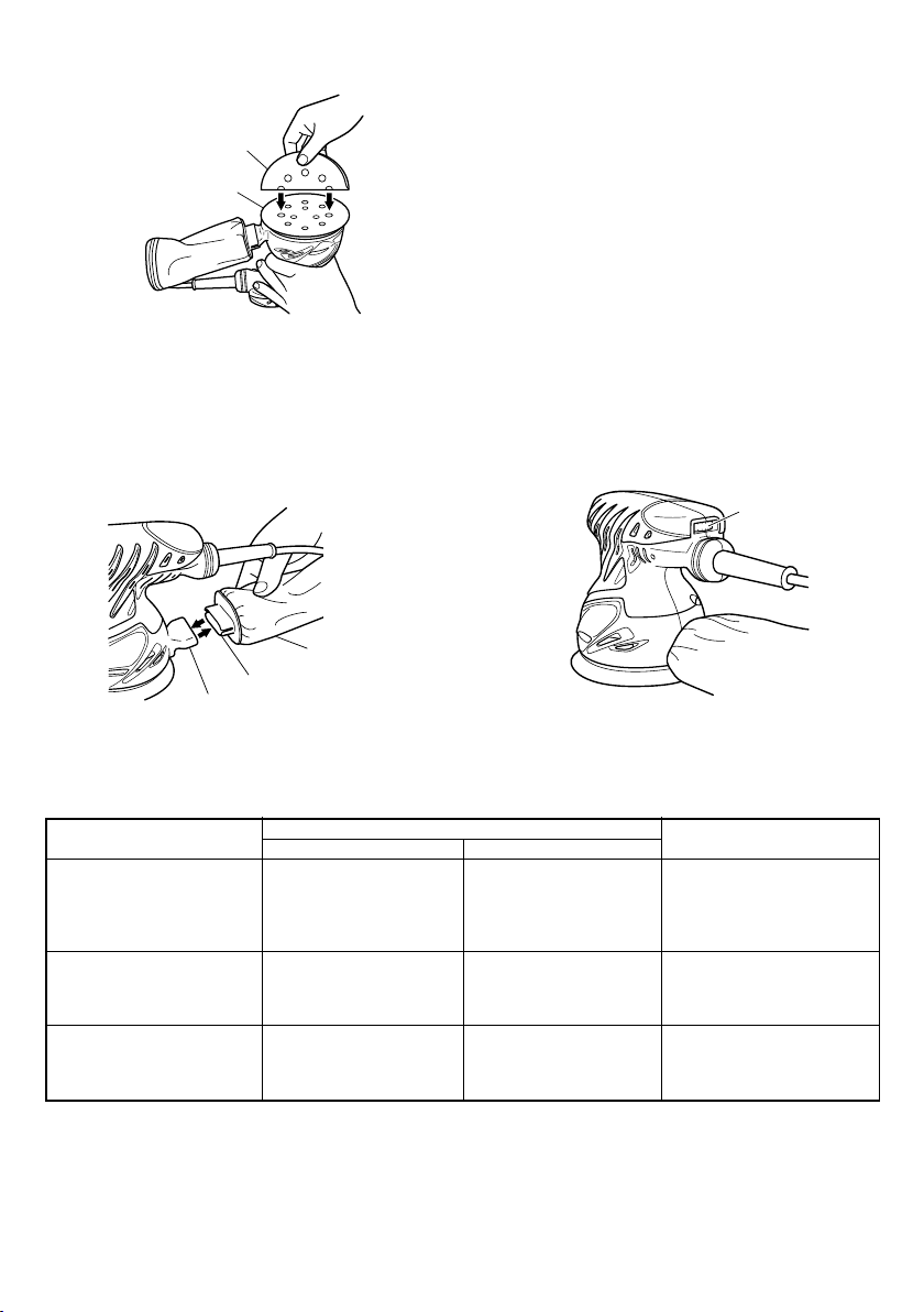
2. How to hold the random orbit sander
While gripping the housing, lightly press the sander
against the surface to be sanded so that the sanding
paper uniformly contacts the surface, as shown in
Fig. 4. DO NOT apply excessive pressure to the sander
while sanding. Excessive-pressure may cause
overload of the motor, reduced service life of the
sanding paper, and lowered sanding or polishing
efficiency.
3. How to move the random orbit sander
Move the sander by either moving it up and down
or by moving it in circles while gradually progressing in a sideways direction (Figs. 5 and 6).
Fig. 4
Fig. 5
4. After installing new sanding paper
Movement of the sander may tend to become
unsteady after new sanding paper has been installed,
because of the new, coarse grain of the paper. This
can be avoided by slightly tilting the sander forward
or backward during sanding or polishing. Sander
movement will become steady as the sanding paper
surface becomes properly abraded.
MOUNTING THE OPTIONAL ACCESSORIES
䡬 Mounting the polyester buff
Since the attachment is a hook-and-loop type as
with the sanding paper, the polyester buff can be
mounted by just pressing it onto the pad (Fig. 7).
Polyester buff
Fig. 7
MAINTENANCE AND INSPECTION
1. Empting and cleaning the Dust Bag
If the dust bag contains too much saw dust, dust
collection will be affected. Empty the dust bag when
it gets full.
Remove the dust bag, open the fastener, and dispose
of the contents.
2. Inspecting the sanding paper
Since use of worn-out sanding paper will degrade
efficiency and cause possible damage to the pad,
replace the sanding paper as soon a excessive
abrasion is noted.
3. Inspecting the mounting screws
Regularly inspect all mounting screws and ensure
that they are properly tightened. Should any of the
screws be loose, retighten them immediately. Failure
to do so could result in serious hazard.
4. Maintenance of the motor
The motor unit winding is the very “heart” of the
power tool.
Exercise due care to ensure the winding does not
become damaged and/or wet with oil or water.
5. Replacing supply cord
If the supply cord of Tool is damaged, the Tool must
be returned to Hitachi Authorized Service Center for
the cord to be replaced.
6. Servicing
Consult an authorized Service Agent in the event of
power tool failure.
Fig. 6
4
Page 6

7. Service parts list
A: Item No.
B: Code No.
C: No. Used
D: Remarks
CAUTION
Repair, modification and inspection of Hitachi Power
Tools must be carried out by an Hitachi Authorized
Service Center.
This Parts List will be helpful if presented with the
tool to the Hitachi Authorized Service Center when
requesting repair or other maintenance.
In the operation and maintenance of power tools, the
safety regulations and standards prescribed in each
country must be observed.
MODIFICATIONS
Hitachi Power Tools are constantly being improved
and modified to incorporate the latest technological
advancements.
Accordingly, some parts (i.e. code numbers and/or
design) may be changed without prior notice.
NOTE
Due to HITACHI’s continuing program of research and
development, the specifications herein are subject to
change without prior notice.
5
Page 7

1 324-249 1
ABC D
SV13YA
2 301-653 7 D4 × 20
3 993-195 1
4 324-207 1
5 ––––––– 1
6 937-631 1
7 984-750 2 D4 × 16
8-1 324-245 1 110V
8-2 324-248 1 220V
8-3 324-244 1 230V
9 959-140 1
8-4 324-247 1 240V
10 938-307 1
11 311-948 1
12 ––––––– 1
13 324-206 1
14 ––––––– 1
15 953-327 1 D8.8
16 322-764 1
17 322-761 1
18 626-VVM 1 626VVC2PS2L
19 322-763 1
20 322-762 1
21 930-483 2
22 999-041 2
23-1 340-616C 1 110V
23-2 340-616E 1 220V-230V
23-3 340-616F 1 240V
24-1 360-696C 1 110V
24-2 360-696E 1 220V-230V
24-3 360-696F 1 240V
25 629-VVM 1 629VVC2PS2L
26 324-521 1
27 324-208 1
28 324-212 1
29 600-2DW 1 6002DDWCMPS2L
30 309-422 1
31 993-244 1 M4 × 12
32 324-210 1
33 324-211 1
34 324-209 1
35 307-109 3 M4 × 16
36 930-039 1
501 310-339 1
502 308-519 1 A-P120
503 324-613 1
6
Page 8

ABC D
SV13YB
7 937-631 1
8 930-039 1
6 984-750 2 D4 × 16
9 938-307 1
10 311-948 1
11 ––––––– 1
12 324-206 1
13 ––––––– 1
14 953-327 1 D8.8
15 322-764 1
16 322-761 1
17 626-VVM 1 626VVC2PS2L
18 322-763 1
19 322-762 1
20 930-483 2
21 999-041 2
22-1 340-618C 1 110V
22-2 340-618E 1 220V-230V
22-3 340-618F 1 240V
23-1 360-698C 1 110V
23-2 360-698E 1 220V-230V
23-3 360-698F 1 240V
24 629-VVM 1 629VVC2PS2L
25 324-521 1
26 324-208 1
27 324-212 1
28 600-2DW 1 6002DDWCMPS2L
29 309-422 1
30 993-244 1 M4 × 12
31 324-210 1
32 324-211 1
33 324-209 1
34 307-109 3 M4 × 16
501 310-339 1
502 308-519 1 A-P120
3 993-195 1
4 324-207 1
2 301-653 7 D4 × 20
5 ––––––– 1
1 324-214 1
7
Page 9

8910
Page 10

Page 11

Page 12

Hitachi Koki Co., Ltd.
Shinagawa Intercity Tower A, 15-1, Konan 2-chome,
Minato-ku, Tokyo, Japan
Code No. C99138911 G
008
Printed in China
 Loading...