

Page 1

Model Orbital Sander
Modèle Ponceuse orbitale
SV 12SG
Modelo Lijadora orbital
SAFETY INSTRUCTIONS AND INSTRUCTION MANUAL
WARNING
IMPROPER OR UNSAFE use of this power tool can result in death or serious bodily
injury!
This manual contains important information about product safety. Please read and
understand this manual BEFORE operating the power tool. Please keep this manual
available for other users and owners before they use the power tool. This manual should
be stored in safe place.
INSTRUCTIONS DE SECURITE ET MODE D’EMPLOI
AVERTISSEMENT
Une utilisation INCORRECTE OU DANGEREUSE de cet outil motorisé peut entraîner la
mort ou de sérieuses blessures corporelles !
Ce mode d’emploi contient d’importantes informations à propos de la sécurité de ce
produit. Prière de lire et de comprendre ce mode d’emploi AVANT d’utiliser l’outil
motorisé. Garder ce mode d’emploi à la disponibilité des autres utilisateurs et
propriétaires avant qu’ils utilisent l’outil motorisé. Ce mode d’emploi doit être conservé
dans un endroit sûr.
INSTRUCCIONES DE SEGURIDAD Y MANUAL DE INSTRUCCIONES
ADVERTENCIA
¡La utilización INAPROPIADA O PELIGROSA de esta herramienta eléctrica puede resultar
en lesiones de gravedad o la muerte!
Este manual contiene información importante sobre la seguridad del producto. Lea y
comprenda este manual ANTES de utilizar la herramienta eléctrica. Guarde este manual
para que puedan leerlo otras personas antes de utilizar la herramienta eléctrica. Este
manual debe ser guardado en un lugar seguro.
DOUBLE INSULATION
DOUBLE ISOLATION
AISLAMIENTO DOBLE
Page 2

English
IMPORTANT SAFETY INFORMATION ................ 3
MEANINGS OF SIGNAL WORDS ........................ 3
SAFETY ...................................................................... 4
GENERAL SAFETY RULES ................................... 4
SPECIFIC SAFETY RULES AND SYMBOLS ......... 6
DOUBLE INSULATION FOR SAFER
OPERATION ................................................... 8
FUNCTIONAL DESCRIPTION .................................... 9
NAME OF PARTS .................................................. 9
SPECIFICATIONS .................................................. 9
CONTENTS
Page
ASSEMBLY AND OPERATION ............................... 10
APPLICATIONS ................................................... 10
PRIOR TO OPERATION ....................................... 10
ORBITAL SANDER OPERATION ........................ 12
HOW TO INSTALL THE
OPTIONAL ACCESSORIES .......................... 13
MAINTENANCE AND INSPECTION ....................... 16
ACCESSORIES ......................................................... 17
STANDARD ACCESSORIES ............................... 17
OPTIONAL ACCESSORIES ................................. 17
Page
Français
INFORMATIONS IMPORTANTES
DE SÉCURITÉ ............................................... 18
SIGNIFICATION DES MOTS
D’AVERTISSEMENT .................................... 18
SECURITE ................................................................ 19
REGLES GENERALE DE SECURITE
REGLES DE SECURITE SPECIFIQUES
ET SYMBOLES ............................................. 21
DOUBLE ISOLATION POUR UN
FONCTIONNEMENT PLUS SUR ................. 23
DESCRIPTION FONCTIONNELLE ........................... 24
NOM DES PARTIES ............................................ 24
SPECIFICATIONS ................................................ 24
TABLE DES MATIERES
Page
...................... 19
Español
INFORMACIÓN IMPORTANTE
SOBRE SEGURIDAD .................................... 34
SIGNIFICADO DE LAS PALABRAS
DE SEÑALIZACIÓN ...................................... 34
SEGURIDAD ............................................................. 35
NORMAS GENERALES DE SEGURIDAD........... 35
NORMAS Y SÍMBOLOS
ESPECÍFICOS DE SEGURIDAD ................... 37
AISLAMIENTO DOBLE PARA OFRECER
UNA OPERACIÓN MÁS SEGURA .............. 39
DESCRIPCIÓN FUNCIONAL .................................... 40
NOMENCLATURA ............................................... 40
SPECIFICATIONS ................................................ 40
Página
ASSEMBLAGE ET FONCTIONNEMENT ................ 25
ENTRETIEN ET INSPECTION .................................. 31
ACCESSOIRES ......................................................... 32
ÍNDICE
MONTAJE Y OPERACIÓN ...................................... 41
MANTENIMIENTO E INSPECCIÓN ........................ 47
ACCESORIOS ........................................................... 48
Page
APPLICATIONS ................................................... 25
AVANT L’UTILISATION ...................................... 25
UTILISATION DE LA PONCEUSE ORBITALE .... 27
INSTALLATION DES ACCESSOIRES EN OPTION .....
ACCESSOIRES STANDARD ............................... 32
ACCESSOIRES SUR OPTION ............................. 32
Página
APLICACIONES ................................................... 41
ANTES DE LA OPERACIÓN ................................ 41
UTILIZACIÓN DE LA LIJADORA ORBITAL ........ 43
MONTAJE DE LOS ACCESORIOS OPCIONALES ..
ACCESORIOS ESTÁNDAR ................................. 48
ACCESORIOS OPCIONALES .............................. 48
28
44
Page 3

English
IMPORTANT SAFETY INFORMATION
Read and understand all of the safety precautions, warnings and operating instructions in
the Instruction Manual before operating or maintaining this power tool.
Most accidents that result from power tool operation and maintenance are caused by the
failure to observe basic safety rules or precautions. An accident can often be avoided by
recognizing a potentially hazardous situation before it occurs, and by observing appropriate
safety procedures.
Basic safety precautions are outlined in the “SAFETY” section of this Instruction Manual
and in the sections which contain the operation and maintenance instructions.
Hazards that must be avoided to prevent bodily injury or machine damage are identified by
WARNINGS on the power tool and in this Instruction Manual.
NEVER use this power tool in a manner that has not been specifically recommended by
HITACHI.
MEANINGS OF SIGNAL WORDS
WARNING indicates a potentially hazardous situations which, if ignored, could result in
death or serious injury.
CAUTION indicates a potentially hazardous situations which, if not avoided, may result in
minor or moderate injury, or may cause machine damage.
NOTE emphasizes essential information.
3
Page 4

English
SAFETY
GENERAL SAFETY RULES
WARNING: Read and understand all instructions.
Failure to follow all instructions listed below, may result in electric shock,
fire and/or serious personal injury.
SAVE THESE INSTRUCTIONS
1. Work Area
(1) Keep your work area clean and well lit. Cluttered benches and dark areas invite
accidents.
(2) Do not operate power tools in explosive atmospheres, such as in the presence of
flammable liquids, gases, or dust. Power tools create sparks which may ignite the
dust of fumes.
(3) Keep bystanders children, and visitors away while operating a power tool.
Distractions can cause you to lose control.
2. Electrical Safety
(1) Double Insulated tools are equipped with a polarized plug (one blade is wider than
the other). This plug will fit in a polarized outlet only one way. If the plug does not
fit fully in the outlet, reverse the plug. If it still does not fit, contact a qualified
electrician to install a polarized outlet. Do not change the plug in any way. Double
Insulation
grounded power supply system.
(2) Avoid body contact with grounded surfaces such as pipes, radiators, ranges and
refrigerators. There is an increased risk of electric shock if your body is grounded.
(3) Do not expose power tools to rain or wet conditions. Water entering a power tool
will increase the risk of electric shock.
(4) Do not abuse the cord. Never use the cord to carry the tools or pull the plug from
a receptacle. Keep cord away from heat, oil, sharp edges or moving parts. Replace
damaged cords immediately. Damaged cords increase the risk of electric shock.
(5) When operating a power tool outside, use an outdoor extension cord marked “W-
A” or “W”. These cords are rated for outdoor use and reduce the risk of electric
shock.
3. Personal Safety
(1) Stay alert, watch what you are doing and use common sense when operating a
power tool. Do not use tool while tires or under the influence of drugs, alcohol,
or medication. A moment of inattention while operating power tools may result in
serious personal injury.
(2) Dress properly. Do not wear loose clothing or jewelry. Contain long hair. Keep
your hair, clothing and gloves away from moving parts. Loose clothes, jewelry, or
long hair can be caught in moving parts.
(3) Avoid accidental starting. Be sure switch is off before plugging in. Carrying tools
with your finger on the switch or plugging in tools that have the switch on invites
4
accidents.
eliminates the need for the three wire grounded power cord and
Page 5

(4) Remove adjusting keys or wrenches before turning the tool on. A wrench or a key
that is left attached to a rotating part of the tool may result in personal injury.
(5) Do not overreach. Keep proper footing and balance at all times. Proper footing and
balance enables better control of the tool in unexpected situations.
(6) Use safety equipment. Always wear eye protection. Dust mask, non-skid safety
shoes, hard hat, or hearing protection must be used for appropriate conditions.
4. Tool Use and Care
(1) Use clamps or other practical way to secure and support the workpiece to a stable
platform. Holding the work by hand or against your body is unstable and may lead
to loss of control.
(2) Do not force tool. Use the correct tool for your application. The correct tool will do
the job better and safer at the rate for which it is designed.
(3) Do not use tool if switch does not turn it on or off. Any tool that cannot be controlled
with the switch is dangerous and must be repaired.
(4) Disconnect the plug form the power source before making any adjustments,
changing accessories, or storing the tool. Such preventive safety measures reduce
the risk of starting the tool accidentally.
(5) Store idle tools out of reach of children and other untrained persons. Tools are
dangerous in the hands of untrained users.
(6) Maintain tools with care. Keep cutting tools sharp and clean. Properly maintained
tools, with sharp cutting edges are less likely to bind and are easier to control.
(7) Check for misalignment or binding of moving parts, breakage of parts, and any
other condition that may affect the tool's operation. If damaged, have the tool
serviced before using. Many accidents are caused by poorly maintained tools.
(8) Use only accessories that are recommended by the manufacturer for your model.
Accessories that may be suitable for one tool, may become hazardous when used
with another tool.
5. Service
(1) Tool service must be performed only by qualified repair personnel. Service or
maintenance performed by unqualified personnel could result in a risk of injury.
(2) When servicing a tool, use only identical replacement parts. Follow instructions in
the Maintenance section of this manual. Use of unauthorized parts or failure to
follow Maintenance Instruction may create a risk of electric shock or injury.
English
5
Page 6

English
SPECIFIC SAFETY RULES AND SYMBOLS
1. Hold tools by insulated gripping surfaces when performing an operation where the
cutting tool may contact hidden wiring or its own cord. Contact with a “live” wire will
make exposed metal parts of the tool “live” and shock the operator.
2. ALWAYS wear ear protectors when using the tool for extended periods.
Prolonged exposure to high intensity noise can cause hearing loss.
3. NEVER touch moving parts.
NEVER place your hands, fingers or other body parts near the tool’s moving parts.
4. NEVER operate without all guards in place.
NEVER operate this tool without all guards or safety features in place and in proper
working order. If maintenance or servicing requires the removal of a guard or safety
feature, be sure to replace the guard or safety feature before resuming operation of the
tool.
5. Use right tool.
Don’t force small tool or attachment to do the job of a heavy-duty tool.
Don’t use tool for purpose not intended —for example— don’t use circular saw for
cutting tree limbs or logs.
6. NEVER use a power tool for applications other than those specified.
NEVER use a power tool for applications other than those specified in the Instruction
Manual.
7. Handle tool correctly.
Operate the tool according to the instructions provided herein. Do not drop or throw
the tool. NEVER allow the tool to be operated by children, individuals unfamiliar with
its operation or unauthorized personnel.
8. Keep all screws, bolts and covers tightly in place.
Keep all screws, bolts, and plates tightly mounted. Check their condition periodically.
9. Do not use power tools if the plastic housing or handle is cracked.
Cracks in the tool’s housing or handle can lead to electric shock. Such tools should not
be used until repaired.
10. Blades and accessories must be securely mounted to the tool.
Prevent potential injuries to youself or others. Blades, cutting implements and
accessories which have been mounted to the tool should be secure and tight.
11. Keep motor air vent clean.
The tool’s motor air vent must be kept clean so that air can freely flow at all times.
Check for dust build-up frequently.
12. Operate power tools at the rated voltage.
Operate the power tool at voltages specified on its nameplate.
If using the power tool at a higher voltage than the rated voltage, it will result in
abnormally fast motor revolution and may damage the unit and the motor may burn
out.
6
Page 7

English
13. NEVER use a tool which is defective or operating abnormally.
If the tool appears to be operating unusually, making strange noises, or otherwise
appears defective, stop using it immediately and arrange for repairs by a Hitachi
authorized service center.
14. NEVER leave tool running unattended. Turn power off.
Don’t leave tool until it comes to a complete stop.
15. Carefully handle power tools.
Should a power tool be dropped or struck against hard materials inadvertently, it may
be deformed, cracked, or damaged.
16. Do not wipe plastic parts with solvent.
Solvents such as gasoline, thinner benzine, carbon tetrachloride, and alcohol may
damage and crack plastic parts. Do not wipe them with such solvents.
Wipe plastic parts with a soft cloth lightly dampened with soapy water and dry
thoroughly.
17. ALWAYS wear eye protection that meets the requirement of the latest revision of ANSI
Standard Z87.1.
18. NEVER leave the orbital sander on floor and so on while spinning.
19. NEVER apply water or lubricating oil, otherwise hazards from electrical shocks may
result.
20. NEVER push the orbital sander too strongly onto a surface.
Pushing the orbital sander too strongly may cause the sanding paper to tear or shorten
the life of the sander itself.
21. ALWAYS operate the orbital sander safely for correct use.
This orbital sander is a portable dry plane surface sander that was designed for finishing
wood and metal surfaces and ground coats.
22. ALWAYS securely installing the sanding paper.
23. ALWAYS wear a protective mask when operating the orbital sander in confined spaces.
24. Definitions for symbols used on this tool
V ............ volts
Hz .......... hertz
A ............ amperes
no .......... no load speed
W ........... watt
........... Class II Construction
---/min ... revolutions per minute
7
Page 8

English
DOUBLE INSULATION FOR SAFER OPERATION
To ensure safer operation of this power tool, HITACHI has adopted a double insulation
design. “Double insulation “ means that two physically separated insulation systems have
been used to insulate the electrically conductive materials connected to the power supply
from the outer frame handled by the operator. Therefore, either the symbol “
words “Double insulation” appear on the power tool or on the nameplate.
Although this system has no external grounding, you must still follow the normal electrical
safety precautions given in this Instruction Manual, including not using the power tool in
wet environments.
To keep the double insulation system effective, follow these precautions:
䡬 Only HITACHI AUTHORIZED SERVICE CENTER should disassemble or assemble this
power tool, and only genuine HITACHI replacement parts should be installed.
䡬 Clean the exterior of the power tool only with a soft cloth moistened with soapy water,
and dry thoroughly.
Never use solvents, gasoline or thinners on plastic components; otherwise the plastic
may dissolve.
” or the
SAVE THESE INSTRUCTIONS
AND
MAKE THEM AVAILABLE TO
OTHER USERS
AND
OWNERS OF THIS TOOL!
8
Page 9

English
FUNCTIONAL DESCRIPTION
NOTE:
The information contained in this Instruction Manual is designed to assist you in the
safe operation and maintenance of the power tool.
NEVER operate, or attempt any maintenance on the tool unless you have first read and
understood all safety instructions contained in this manual.
Some illustrations in this Instruction Manual may show details or attachments that differ
from those on your own power tool.
NAME OF PARTS
Switch
Nameplate
Housing (B)
Pad
Housing (A)
Base
Paper Clip
Fig. 1
Dust Bug
SPECIFICATIONS
Motor Single Phase, Series Commutator Motor
Power source Single Phase 120V AC 60 Hz
Current 1.7 A
No-load speed 14000/min
Sanding pad size 4-3/8” × 4” (110 mm × 100 mm)
Sanding paper size 4-1/2” × 5-1/2” (114 mm × 140 mm)
Weight 2.42 lbs (1.1 kg)
9
Page 10
English
ASSEMBLY AND OPERATION
APPLICATIONS
䡬 Finish polishing of woodwork surfaces.
䡬 Sanding surfaces of woodwork or sheet metal prior to painting, etc.
PRIOR TO OPERATION
1. Power source
Ensure that the power source to be utilized conforms to the power source requirements
specified on the product nameplate.
2. Power switch
Ensure that the switch is in the OFF position. If the plug is connected to a receptacle
while the switch is in the ON position, the power tool will start operating immediately
and can cause serious injury.
3. Extension cord
When the work area is far away from the power source, use an extension cord of
sufficient thickness and rated capacity. The extension cord should be kept as short as
practicable.
WARNING:
Damaged cord must be replaced or repaired.
4. Check the receptacle
If the receptacle only loosely accepts the plug, the receptacle must be repaired. Contact
a licensed electrician to make appropriate repairs.
If such a fautly receptacle is used, it may cause overheating, resulting in a serious
hazard.
5. Check your working environment
Ensure the following before operation;
䡬 No flammable gas, liquid, or object at worksite.
䡬 Sanding thin steel sheet may cause a high booming sound.
In this case, place a rubber mat under the workpiece.
䡬 Take appropriate noise preventive measures to prevent adverse affects on the
environment by electrical noise.
䡬 Clear the area of children or unauthorized personnel.
10
Page 11

English
6. Installing the sanding paper
(1) Peel off the paper on the backside of the
quick stick sanding paper.
Since adhesive agent is applied on the paper
on the backside of the quick stick sanding
paper, make sure that it is not exposed to
dust or other particles. Fig. 2.
(2) To attach the quick stick sanding paper,
match its holes to the holes in the quick stick
rubber pad.
NOTE:
Wipe off any dust or oil on the pad before
attaching the sanding paper to it.
(3) Surely attach the quick stick sanding paper
by strongly and evenly pressing with your
palm. (Fig. 4)
NOTE:
If you reattach the quick stick sanding paper
several times, its adhesive strength will
become lowered. Please try to attach it only
once.
7. Attaching and removing the dust bag
(1) Attaching the dust bag
As shown in Fig. 5, hold the dust gate and
push it in the direction of arrow A to attach
it to the dust outlet.
(2) Removing the dust bag
As shown in Fig. 5, hold the dust gate and
pull it in the direction of arrow B to remove
it from the dust outlet.
Paper on backside
Fig. 2
Quick stick
sanding paper
Quick stick
rubber pad
Fig. 3
Press strongly
Fig. 4
A
B
Dust outlet
Fig. 5
Dust bag
Dust gate
11
Page 12
English
ORBITAL SANDER OPERATION
WARNING: Never apply water or grinding fluid when sanding. This could result in
electrical shock.
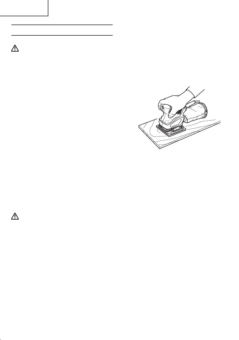
1. How to hold the orbital sander
While gripping the housing, lightly press the
sander against the surface to be sanded so
that the sanding paper uniformly contacts
the surface, as shown in Fig. 6. DO NOT
apply excessive pressure to the sander while
sanding. Excessive pressure may cause
overload of the motor, reduced service life
of the sanding paper, and lowered sanding
or polishing efficiency.
2. How to move the orbital sander
For optimum operating efficiency,
alternately move the sander forward and
backward at a constant speed and balance.
3. Switching the sander ON and OFF
The power can be turned on by setting the
lever to ON (1) and turned off by setting the
lever to OFF (0).
Fig. 6
NOTE:
Never turn the power switch ON when the sander is contacting the surface to be sanded.
This is necessary to preclude damage to the material. The same applies when switching
the power OFF.
CAUTION:
䢇 lmmediately after use, always turn the sander off and unplug it.
䢇 Since the sander may suck in dust and debris, be careful not to place it where there is
much dust and debris when it is still spinning right after use.
12
Page 13

English
HOW TO INSTALL THE OPTIONAL ACCESSORIES
WARNING: Be sure to switch power OFF and disconnect the plug to avoid
accidents.
1. Installing the sponge pad (velcro type), the felt pad and the round rubber pad.
4-3/8” × 4”
(110 × 100 mm)
Quick stick pad
4-3/8” × 4”
(110 × 100 mm)
Sponge pad
(Velcro type),
felt pad
Sponge pad or felt pad
CAUTION: Replace only the pad and use the other parts just as they are. The sander
will vibrate greatly if parts other than the pad are removed or exchanged.
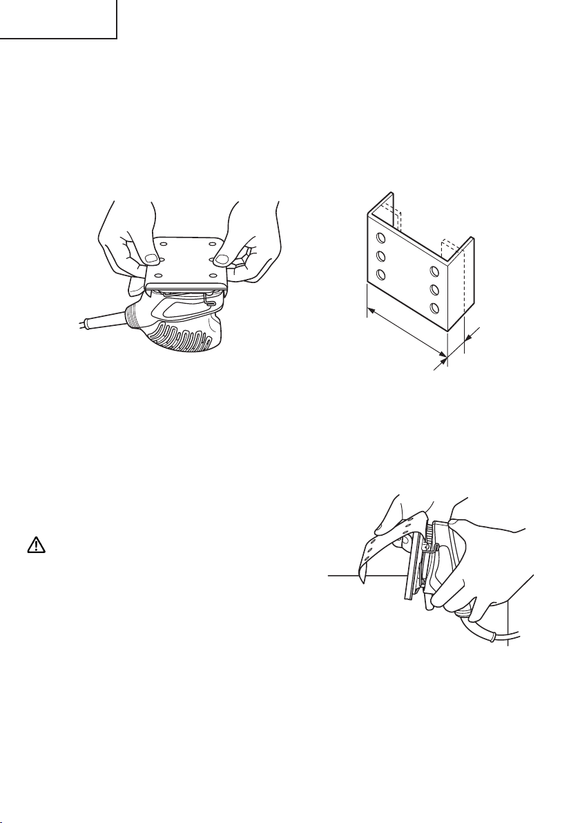
䡬 Loosen the four M4 × 10
screws and remove the quick
stick pad.
5” (125 mm)
round rubber
pad
䡬 Tighten the four M4 × 10
screws and attach the
sponge pad, felt pad
or round rubber pad.
Round
rubber pad
Fig. 7
13
Page 14
English
2. Installing the sanding paper
[4-1/2” × 5-1/2” (114 × 140 mm) sanding paper (Clip type)]
(1) Bending the sanding paper:
䡬 Position the sander with its pad side facing upward as shown in Fig. 8. Place the sanding
paper on the pad so that the center of the sanding paper is aligned with the center of
the pad, and bend both ends of the sanding paper at a 90° angle.
䡬 Then, bend both ends again in the manner shown in Fig. 9. The sanding paper is now
ready to be installed on the sander.
Fig. 8 Fig. 9
(2) Installing the sanding paper
While ensuring that the cord is not bent,
place the sander on a workbench as shown
in Fig. 10, and insert one end of the sanding
paper (bent section). Next, insert the
remaining bent section in the same manner.
CAUTION:
The sanding paper must be precisely
installed on the pad, ensuring that there is
ample tension (leaving no slack). Loosely
installed sanding paper could result in
unevenly sanded surfaces and/or damage
to the sanding paper itself.
4” (100 mm)
Fig. 10
25/64” (10 mm)
14
Page 15

English
[4-3/8” × 4” (110 × 100 mm) sanding paper (Velcro type)]
(1) Match the holes in the sanding paper (Velcro type) to the holes in the sponge pad
(velcro type).
Sanding paper (Velcro type)
Sponge pad
(Velcro type)
Fig. 11
(2) Surely attach the sanding paper (Velcro
type) by strongly and evenly pressing with
your palm. (Fig. 12)
[5” (125 mm) quick stick sanding paper]
Attach the quick stick sanding paper to the 5” (125 mm) round rubber pad in the same
way as shown in ”6. Installing the sanding paper” on page 11.
Press strongly
Fig. 12
3. Opening holes in the sanding paper
with the punch plate
Dust collecting capacity will improve if the
punch plate is used to open holes in sanding
paper without holes.
Punch plate
Fig. 13
15
Page 16

English
MAINTENANCE AND INSPECTION
WARNING: Be sure to switch power OFF and disconnect the plug from the
receptacle during maintenance and inspection.
1. Emptying and cleaning the dust bag
If the dust bag contains too much saw dust, dust collection will be affected. Empty the
dust bag when it gets full.
Remove the dust bag, open the fastener, and dispose of the contents.
2. Inspecting the sanding paper
Since use of worn-out sanding paper will degrade efficiency and cause possible damage
to the pad, replace the sanding paper as soon as excessive abrasion is noted.
3. Inspecting the screws
Regularly inspect all screws and ensure that they are fully tightened. Should any of the
screws be loosened, retighten them immediately.
WARNING: Using this orbital sander with loosened screws is extremely dangerous.
4. Inspecting the carbon brushes
For your continued safety and electrical shock protection, carbon brush inspection and
replacement on this tool should ONLY be performed by a HITACHI AUTHORIZED
SERVICE CENTER.
5. Service and repairs
All quality power tools will eventually require servicing or replacement of parts because
of wear from normal use. To assure that only authorized replacement parts will be
used, all service and repairs must be performed by a HITACHI AUTHORIZED SERVICE
CENTER, ONLY.
6. Service parts list
CAUTION: Repair, modification and inspection of Hitachi Power Tools must be carried
out by an Hitachi Authorized Service Center.
This Parts List will be helpful if presented with the tool to the Hitachi Authorized Service
Center when requesting repair or other maintenance. In the operation and maintenance
of power tools, the safety regulations and standards prescribed in each country must
be observed.
16
Page 17

English
ACCESSORIES
WARNING: ALWAYS use Only authorized HITACHI replacement parts and
accessories. NEVER use replacement parts or accessories which are
not intended for use with this tool. Contact HITACHI if you are not sure
whether it is safe to use a particular replacement part or accessory
with your tool. The use of any other attachment or accessory can be
dangerous and could cause injury or mechanical damage.
NOTE:
Accessories are subject to change without any obligation on the part of the HITACHI.
STANDARD ACCESSORIES
(1) Sanding paper (quick stick type) (Grain: #80) (Code No. 310348) .................................. 1
(4-3/8” × 4” (110 mm × 100 mm)
(2) Dust bag (Code No. 323004) .............................................................................................. 1
OPTIONAL ACCESSORIES …………… sold separately
䡬 Sanding paper
Size Type Grit No. Code No.
4-1/2” × 5-1/2”
(114 mm × 140 mm)
4-3/8” × 4”
(110 mm × 100 mm)
4-3/8” × 4”
(110 mm × 100 mm) AA120 310350
5” (125 mm) Velcro type AA60 310353
Paper clip type AA100 310342
Velcro type AA100 310345
Quick stick type
AA60 310341
AA150 310343
AA60 310344
AA150 310346
AA60 310347
AA80 310348
AA100 310349
AA150 310351
AA180 310352
䡬 Felt pad 4-3/8” × 4” (110 mm × 100 mm) (Code No. 310354)
䡬 Sponge pad (velcro type) 4-3/8” × 4” (110 mm × 100 mm) (Code No. 310355)
䡬 Round rubber pad 5” (125 mm) (Code No. 310356)
䡬 Punch plate (Code No. 310340)
NOTE:
Specifications are subject to change without any obligation on the part of the HITACHI.
17
Page 18

Français
INFORMATIONS IMPORTANTES DE SÉCURITÉ
Lire et comprendre toutes les précautions de sécurité, les avertissements et les instructions
de fonctionnement dans ce mode d’emploi avant d’utiliser ou d’entretenir cet outil motorisé.
La plupart des accidents causés lors de l’utilisation ou de l’entretien de l’outil motorisé
proviennent d’un non respect des règles ou précautions de base de sécurité. Un accident
peut la plupart du temps être évité si l’on reconnaît une situation de danger potentiel avant
qu’elle ne se produise, et en observant les procédures de sécurité appropriées.
Les précautions de base de sécurité sont mises en évidence dans la section “SECURITE”
de ce mode d’emploi et dans les sections qui contiennent les instructions de fonctionnement
et d’entretien.
Les dangers qui doivent être évités pour prévenir des blessures corporelles ou un
endommagement de la machine sont identifiés par AVERTISSEMENTS sur l’outil motorisé
et dans ce mode d’emploi.
NE JAMAIS utiliser cet outil motorisé d’une manière qui n’est pas spécifiquement
recommandée par HITACHI.
SIGNIFICATION DES MOTS D’AVERTISSEMENT
AVERTISSEMENT indique des situations potentiellement dangereuses qui, si elles sont
ignorées, pourraient entraîner la mort ou de sérieuses blessures.
PRECAUTION indique des situations dangereuses potentilles qui, si elles ne sont pas évitées,
peuvent entraîner de mineures et légères blessures ou endommager la machine.
REMARQUE met en relief des informations essentielles.
18
Page 19

Français
SECURITE
REGLES GENERALE DE SECURITE
AVERTISSEMENT: Lire et coxmprendre toutes les instructions.
Un non respect de toutes les instructions ci-dessous peut
entraîner une électrocution, un incendie et/ou de sérieuses
blessures personnelles.
CONSERVER CES INSTRUCTIONS
1. Zone de travail
(1) Garder la zone de travail propre et bien éclairée. Les établis mal rangés et les
zones sombres invitent aux accidents.
(2) Ne pas utiliser les outils motorisés dans une atmosphère explosive, telle qu’en
présence de liquides inflammables, de gaz ou de poussières. Les outils motorisés
créent des étincelles qui risquent d’enflammer la poussière ou les vapeurs.
(3) Tenir les spectateurs, les enfants et les visiteurs éloignés, lors de l’utilisation de
l’outil motorisé. Une distraction peut faire perdre le contrôle de la machine.
2. Sécurité électrique
(1) Les outils à double isolation sont équipés d’une fiche polarisée (une lame est plus
large que l’autre). Cette fiche ne pénétrera dans une prise secteur polarisée que
dans un sens. Si la fiche ne rentre pas complètement dans la prise, la retourner. Si
elle ne rentre toujours pas, contacter un électricien qualifié pour installer une prise
polarisée. Ne pas modifier la fiche d’aucune façon. La double isolation
le besoin d’un cordon d’alimentation à trois fils et d’un système d’alimentation
avec mises à la terre.
(2) Eviter tout contact corporel avec les surfaces mises à la terre telles que les
canalisations, les radiateurs, les réchauds et les réfrigérateurs. Il y a un risque
accru d’électrocution si son corps est mis à la terre.
(3) Ne pas exposer les outils motorisés à la pluie ou à l’humidité. De l’eau pénétrant à
l’intérieur de l’outil motorisé augmente le risque d’électrocution.
(4) Ne pas maltraiter le cordon d’alimentation. Ne jamais utiliser le cordon pour porter
les outils ou tirer sur la fiche du réceptacle. Garder le cordon à l’écart de la chaleur,
de l’huile, des arêtes coupantes ou des pièces en mouvement. Remplacer les
cordons endommagés immédiatement. Des cordons endommagés augmentent le
risque d’électrocution.
(5) Lors de l’utilisation d’un outil motorisé, utiliser un cordon de rallonge extérieur
marqué “W-A” ou “W”. Ces cordons sont prévus pour une utilisation extérieure et
réduisent les risques d’électrocution.
3. Sécurité personnelle
(1) Rester sur ses gardes, regarder ce que l’on fait et utiliser son sens commun lors de
l’utilisation d’un outil motorisé. Ne pas utiliser un outil en état de fatigue ou sous
l’influence de drogues, d’alcool ou de médicaments. Un moment d’inattention lors
de l’utilisation de l’outil motorisé peut entraîner de sérieuses blessures personnelles.
élimine
19
Page 20

Français
(2) S’habiller correctement. Ne pas porter des vêtements larges ou des bijoux. Attacher
les cheveux longs. Tenir ses cheveux, vêtements et ses gants éloignés des parties
mobiles. Les vêtements larges, les bijoux et les cheveux longs peuvent se prendre
dans les parties mobiles.
(3) Eviter tout démarrage accidentel. S’assurer que le l’interrupteur d’alimentation
est sur la position d’arrêt avant de brancher la machine. Transporter l’appareil
avec les doigts sur l’interrupteur d’alimentation ou brancher un outil avec
l’interrupteur sur la position marche invite aux accidents.
(4) Retirer les clefs d’ajustement ou les commutateurs avant de mettre l’outil sous
tension. Une clef qui est laissée attachée à une partie tournante de l’outil peut
provoquer une blessure personnelle.
(5) Ne pas trop présumer de ses forces. Garder en permanence une position et un
équilibre correct. Une position et un équilibre correct permettent un meilleur contrôle
de l’outil dans des situations inattendues.
(6) Utiliser un équipement de sécurité. Toujours porter une protection pour les yeux.
Utiliser un masque à poussière, des chaussures de sécurité antidérapantes, un
casque dur et une protection pour les oreilles dans les conditions appropriées.
4. Utilisation de l’outil et entretien
(1) Utiliser un étau ou toutes autres façons de fixer et maintenir la pièce à usiner sur
une plate-forme stable. Tenir la pièce avec la main ou contre son corps est instable
et peut conduire à une perte de contrôle de l’outil.
(2) Ne pas forcer sur l’outil. Utiliser l’outil correct pour l’application souhaitée. L’outil
correct réalisera un meilleur et plus sûr travail dans le domaine pour lequel il a été
conçu.
(3) Ne pas utiliser un outil s’il ne se met pas sous ou hors tension avec un interrupteur.
Un outil qui ne peut pas être commandé avec un interrupteur est dangereux et doit
être réparé.
(4) Déconnecter la fiche de la source d’alimentation avant de réaliser tout ajustement,
changement d’accessoires ou pour ranger l’outil. De telles mesures de sécurité
réduisent le risque que l’outil ne démarre accidentellement.
(5) Ranger les outils inutilisés hors de la portée des enfants et des autres personnes
inexpérimentées. Les outils sont dangereux dans les mains de personnes
inexpérimentées.
(6) Entretenir les outils avec soin. Maintenir les outils de coupe affûtés et propres.
Des outils correctement entretenus, avec des tranchants bien affûtés, sont moins
susceptibles de se coincer et sont plus faciles à contrôler.
(7) Vérifier les défauts d’alignement ou grippage des parties mobiles, les ruptures
des pièces et toutes les autres conditions qui peuvent affecter le fonctionnement
des outils. En cas de dommage, faire réparer l’outil avant de l’utiliser. Beaucoup
d’accidents sont causés par des outils mal entretenus.
(8) Utiliser uniquement les accessoires recommandés par le fabricant pur le modèle
utilisé. Des accessoires qui peuvent convenir à un outil, peuvent devenir dangereux
lorsqu’ils sont utilisés avec un autre outil.
5. Réparation
(1) La réparation de l’outil ne doit être réalisée uniquement par un réparateur qualifié.
Une réparation ou un entretien réalisé par un personnel non qualifié peut entraîner
des risques de blessures.
20
Page 21

Français
(2) Lors de la réparation d’un outil, utiliser uniquement des pièces de rechange
identiques. Suivre les instructions de la section d’entretien de ce mode d’emploi.
L’utilisation de pièces non autorisées ou un non respect des instructions d’entretien
peut créer un risque d’électrocution ou de blessures.
REGLES DE SECURITE SPECIFIQUES ET SYMBOLES
1. Tenir les outils par les surfaces de grippage lors de la réalisation d’opération où l’outil
de coupe risque d’entrer en contact avec des câbles cachés ou son propre cordon. Un
contact avec un fil “sous tension” mettra les parties métalliques de l’outil “sous tension”
et électrocutera l’utilisateur.
2. TOUJOURS porter des bouchons d’oreille lors de l’utilisation de l’outil pendant de
longues périodes.
Une exposition prolongée à un son de forte intensité peut endommager
l’ouïe de l’utilisateur.
3. NE JAMAIS toucher les parties mobiles.
NE JAMAIS placer ses mains, ses doigts ou toute autre partie de son corps près des
parties mobiles de l’outil.
4. NE JAMAIS utiliser l’outil sans que tous les dispositifs de sécurité ne soient en place.
NE JAMAIS faire fonctionner cet outil sans que tous les dispositifs et caractéristiques
de sécurité ne soient en place et en état de fonctionnement. Si un entretien ou une
réparation nécessite le retrait d’un dispositif ou d’une caractéristique de sécurité,
s’assurer de bien remettre en place le dispositif ou la caractéristique de sécurité avant
de recommencer à utiliser l’outil.
5. Utiliser l’outil correct.
Ne pas forcer sur un petit outil ou accessoire pour faire le travail d’un outil de grande
puissance.
Ne pas utiliser un outil pour un usage pour lequel il n’a pas été prévu : par exemple, ne
pas utiliser une scie circulaire pour couper des branches d’arbre ou des bûches.
6. NE JAMAIS utiliser un outil motorisé pour des applications autres que celles spécifiées.
NE JAMAIS utiliser un outil motorisé pour des applications autres que celles spécifiées
dans le mode d’emploi.
7. Manipuler l’outil correctement.
Utiliser l’outil de la façon indiquée dans ce mode d’emploi. Ne pas laisser tomber ou
lancer l’outil. NE JAMAIS permettre que l’outil soit utilisé par des enfants, des personnes
non familiarisées avec son fonctionnement ou un personnel non autorisé.
8. Maintenir toutes les vis, tous les boulons et les couvercles fermement en place.
Maintenir toutes les vis, tous les boulons et les couvercles fermement montés. Vérifier
leurs conditions périodiquement.
21
Page 22

Français
9. Ne pas utiliser les outils motorisés si le revêtement de plastique ou la poignée est
fendu.
Des fentes dans le revêtement ou la poignée peuvent entraîner une électrocution. De
tels outils ne doivent pas être utilisés avant d’être réparé.
10. Les lames et les accessoires doivent être fermement montés sur l’outil.
Eviter les blessures potentielles personnelles et aux autres. Les lames, les instruments
de coupe et les accessoires qui ont été montés sur l’outil doivent être fixés et serrés
fermement.
11. Garder propres les évents d’air du moteur.
Les évents d’air du moteur doivent être maintenus propres de façon que l’air puisse
circuler librement tout le temps. Vérifier les accumulations de poussière fréquemment.
12. Utiliser l’outil motorisé à la tension nominale.
Utiliser l’outil motorisé à la tension spécifiée sur sa plaque signalétique.
Si l’on utilise l’outil motorisé avec une tension supérieure à la tension nominale, il en
résultera une rotation anormalement trop rapide du moteur et cela risque
d’endommager l’outil et le moteur risque de griller.
13. NE JAMAIS utiliser un outil défectueux ou qui fonctionne anormalement.
Si l’outil n’a pas l’air de fonctionner normalement, fait des bruits étranges ou sans cela
paraît défectueux, arrêter de l’utiliser immédiatement et le faire réparer par un centre
de service Hitachi autorisé.
14. NE JAMAIS laisser fonctionner l’outil sans surveillance. Le mettre hors tension.
Ne pas abandonner l’outil avant qu’il ne soit complètement arrêté.
15. Manipuler l’outil motorisé avec précaution.
Si un outil motorisé tombe ou frappe un matériau dur accidentellement, il risque d’être
déformé, fendu ou endommagé.
16. Ne pas essuyer les parties en plastique avec du solvant.
Les solvants comme l’essence, les diluants, la benzine, le tétrachlorure de carbone et
l’alcool peuvent endommager et fissurer les parties en plastique. Ne pas les essuyer
avec de tels solvants.
Essuyer les parties en plastique avec un chiffon doux légèrement imbibé d’une solution
d’eau savonneuse et sécher minutieusement.
17. TOUJOURS porter des lunettes de protection qui respectent les dernières révisions du
Standard ANSI Z87.1.
18. NE JAMAIS laisser la ponceuse orbitale sur le sol pendant qu’elle tourne.
19. NE JAMAIS appliquer d’eau ni d’huile de lubrification, car cela pourrait provoquer des
chocs électriques.
20. NE JAMAIS appuyer la ponceuse orbitale trop fort contre une surface.
Le fait d’appuyer trop fort sur la ponceuse orbitale peut déchirer la toile émeri ou
raccourcir la durée de service de la ponceuse elle-même.
21. TOUJOURS utiliser la ponceuse orbitale en toute sécurité pour assurer une utilisation
correcte.
22
Page 23

Français
Cette ponceuse orbitale est une ponceuse à surface plane sèche portable qui a été
conçue pour le ponçage des surfaces en bois ou en métal et des couches de fond.
22. TOUJOURS installer la ponceuse orbitale solidement.
23. TOUJOURS porter un masque de protection lors de l’utilisation de la ponceuse orbitale
dans un espace clos.
24. Définitions pour les symboles utilisés sur cet outil
V ............volts
Hz .......... hertz
A ............ ampères
no .......... vitesse sans charge
W ........... watt
........... Construction de classe II
---/min ... tours par minute
DOUBLE ISOLATION POUR UN FONCTIONNEMENT PLUS SUR
Pour assurer un fonctionnement plus sûr de cet outil motorisé, HITACHI a adopté une
conception à double insolation. “Double isolation” signifie que deux systèmes d’isolation
physiquement séparés ont été utilisés pour isoler les matériaux conducteurs d’électricité
connectés à l’outil motorisé à partir du cadre extérieur manipulé par l’utilisateur. C’est
pourquoi, le symbole “
sur l’outil motorisé ou sur la plaque signalétique.
Bien que ce système n’ait pas de mise à terre extérieure, il est quand même nécessaire de
suivre les précautions de sécurité électrique données dans ce mode d’emploi, y-compris
de ne pas utiliser l’outil motorisé dans un environnement humide.
Pour garder le système de double isolation effectif, suivre ces précautions:
䡬 Seuls les CENTRES DE SERVICE AUTORISES HITACHI peuvent démonter et remonter
cet outil motorisé et uniquement des pièces de rechange HITACHI garanties d’origine
doivent être utilisées.
䡬 Nettoyer l’extérieur de l’outil motorisé uniquement avec un chiffon doux légèrement
imbibé d’une solution savonneuse et essuyer minutieusement.
Ne jamais utiliser des solvants, de l’essence ou des diluants sur les parties en plastique ;
sinon le plastique risquerait de se dissoudre.
” ou les mots “Double insulation” (double isolation) apparaissent
CONSERVER CES INSTRUCTIONS
ET
LES METTRE A LA DISPOSITION
DES AUTRES UTILISATEURS
ET
PROPRIETAIRES DE CET OUTIL !
23
Page 24

Français
DESCRIPTION FONCTIONNELLE
REMARQUE:
Les informations contenues dans ce mode d’emploi sont conçues pour assister
l’utilisateur dans une utilisation sans danger et un entretien de l’outil motorisé.
NE JAMAIS utiliser ni entreprendre une révision de l’outil sans avoir d’abord lu et compris
toutes les instructions de sécurité contenues dans ce manuel.
Certaines illustrations dans ce mode d’emploi peuvent montrer des détails ou des
accessoires différents de ceux de l’outil motorisé utilisé.
NOM DES PARTIES
Interrupteur
Plaque signalétique
Attache-papierLogement (B)
Logement (A)
Socle
Plateau
Sac à poussière
Fig. 1
SPECIFICATIONS
Moteur Moteur série monophasé à collecteur
Source d’alimentation Secteur, 120V 60 Hz, monophaséz
Courant 1,7 A
Vitesse sans charge 14000/min
Dimension du coussinet 4-3/8” × 4” (110 mm × 100 mm)
Dimension du papier du verre 4-1/2” × 5-1/2” (114 mm × 140 mm)
Poids 2,42 lbs (1,1 kg)
24
Page 25

Français
ASSEMBLAGE ET FONCTIONNEMENT
APPLICATIONS
䡬 Polissage de finition des surfaces en bois.
䡬 Ponçage des surfaces en bois ou en métal avant l'application de peinture, etc.
AVANT L’UTILISATION
1. Source d’alimentation
S’assurer que la source d’alimentation qui doit être utilisée est conforme à la source
d’alimentation requise spécifiée sur la plaque signalétique du produit.
2. Interrupteur d’alimentation
S’assurer que l’interrupteur est sur la position OFF (arrêt). Si la fiche est connectée sur
une prise alors que l’interrupteur est sur la position ON (marche), l’outil motorisé
démarrera immédiatement risquant de causer de sérieuses blessures.
3. Cordon prolongateur
Quand la zone de travail est éloignée de la source d’alimentation, utiliser un cordon
prolongateur d’épaisseur et de capacité nominale suffisante. Le cordon prolongateur
doit être aussi court que possible.
AVERTISSEMENT:
Tout cordon endommagé devra être remplacé ou réparé.
4. Vérifier la prise
Si la prise reçoit la fiche avec beaucoup de jeu, elle doit être réparée. Contacter un
électricien licencié pour réaliser les réparations nécessaires.
Si une telle prise défectueuse est utilisée, elle peut causer une surchauffe entraînant
des dangers sérieux.
5. Vérifier l’environnement de travail
S’assurer des points suivants avant de travail;
䡬 Pas de gaz, liquide ou objet inflammable sur le chantier.
䡬 Le ponçage d’une tôle d’acier fine peut provoquer un bruit assourdissant.
Dans ce cas, mettre un tapis en caoutchouc sous la pièce.
䡬 Prendre les mesures anti-bruit qui s’imposent pour éviter tout effet néfaste du
bruit électrique sur l’environnement.
䡬 Eloigner les enfants et toutes les personnes non autorisées.
25
Page 26

Français
6. Fixation de la toile émeri
(1) Décoller le papier au dos de la toile émeri à
fixation rapide.
Etant donné qu’il y a un agent adhésif au
dos de la toile émeri à fixation rapide, bien
veiller à ne pas l’exposer à la poussière ni à
aucune autre particule. Fig. 2
(2) Pour fixer la toile émeri à fixation rapide,
faire correspondre ses orifices avec ceux du
plateau en caoutchouc à fixation rapide.
REMARQUE :
Enlever toute poussière ou toute graisse du
plateau avant d’y fixer la toile émeris.
(3) Fixer solidement la toile émeri à fixation
rapide en appuyant dessus fortement et de
façon uniforme avec la paume. (Fig. 4)
REMARQUE :
Si l’on réattache la toile émeri à fixation
rapide plusieurs fois, son pouvoir adhésif
diminuera. Essayer de la fixer une seule fois.
7. Fixation et retrait du sac à poussière
(1) Fixation du sac à poussière
Tenir l’entonnoir de poussière et le pousser
dans le sens de la flèche A pour le fixer au
déversoir de poussière, comme indiqué par
la Fig. 5.
(2) Retrait du sac à poussière
Tenir l’entonnoir de poussière et le tirer dans
le sens de la flèche B pour le détacher du
déversoir de poussière, comme indiqué par
la Fig. 5.
Papier du dos
Fig. 2
Toile émeri à
fixation rapide
Plateau en
caoutchouc
à fixation
rapide
Fig. 3
Appuyer fortement
Fig. 4
A
B
Déversoir
de poussière
Fig. 5
26
Sac à poussière
Volet à poussière
Page 27

Français
UTILISATION DE LA PONCEUSE ORBITALE
AVERTISSEMENT : Ne jamais utiliser d’eau ou de fluide de ponçage au cours
des opérations de ponçage. Cela peut entraîner un risque
de commotion électrique.
1. Comment tenir la ponceuse orbitale
Tenir l’enveloppe et presser légèrement la
ponceuse sur la surface à poncer de manière
à ce que le papier de verre soit
uniformément en contact avec la surface à
poncer, comme indiqué par la Fig. 6. NE
JAMAIS appliquer une pression excessive
sur la ponceuse au cours du ponçage. Une
pression excessive peut provoquer une
surchage du moteur, réduire la durée de vie
du papier de verre et diminuer l’efficacité
du ponçage ou du polissage.
2. Comment déplacer la ponceuse orbitale
Pour obtenir une efficacité de
fonctionnement optimale, déplacer la
ponceuse alternativement vers l’avant et
vers l’arrière tout en maintenant la vitesse
et l’équilibre constants.
3. Mise en MARCHE et ARRET de la ponceuse
La ponceuse peut être mise sous tension en
mettant le levier sur la position MARCHE
(ON) (1) et hors tension en mettant ce levier
sur ARRET (OFF) (0).
Fig. 6
NOTE:
Ne jamais mettre l’interrupteur d’alimentation sur MARCHE (ON) lorsque la ponceuse
est en contact avec la surface à poncer. Cette précaution est nécessaire pour éviter
d’endommager la pièce à travailler. La même précaution doit être prise lorsque
l’interrupteur d’alimentation est mis sur ARRET (OFF).
ATTENTION:
䢇 Toujours éteindre la ponceuse orbitale et la débrancher immédiatement après
l’utilisation.
䢇 La ponceuse pouvant aspirer de la poussière et des débris, veiller à ne pas la placer
dans un endroit accusant une forte présence de poussière et de débris lorsqu’elle est
encore en train de tourner tout de suite après l’utilisation.
27
Page 28

Français
INSTALLATION DES ACCESSOIRES EN OPTION
AVERTISSEMENT : Pour éviter tout accident, bien couper l’interrupteur
d’alimentation (OFF) et débrancher la fiche.
1. Installation du plateau en mousse (type Velcro), du plateau en feutre et du
plateau en caoutchouc rond.
Plateau à fixation
rapide de 4-3/8” ×
4” (110 × 100 mm)
Plateau en
mousse de 4-3/8”
× 4” (110 × 100
mm) (Type Velcro)
Plateau en feutre
Plateau en mousse ou
plateau en feutre
ATTENTION : Remplacer seulement le plateau et utiliser les autres pièces telles quelles.
La ponceuse vibrera considérablement si l’on retire ou qu’on remplace
d’autres pièces que le plateau.
䡬 Desserrer les quatre vis
M4 × 10 et retirer le plateau
à fixation rapide.
Plateau en
caoutchouc
rond de 5”
(125 mm)
䡬 Serrer les quatre vis
M4 × 10 et fixer le
plateau en mousse,
le plateau en
feutre et le plateau
en caoutchouc
rond.
Plateau en
caoutchouc
rond
Fig. 7
28
Page 29

Français
2. Mise en place du papier de verre
[Toile émeri de 4-1/2” × 5-1/2” (114 × 140 mm) (type agrafe)]
(1) Pliage du papier de verre:
䡬 Placer la ponceuse avec le coussinet dirigé vers le haut, comme indiqué par la Fig. 8.
Placer le papier de verre sur le coussinet en prenant soin de faire coïncider la ligne médiane
du papier avec celle du coussinet. Puis, plier les deux extrémités du papier à 90°.
䡬 Ensuite, plier à nouveau les deux extrémités comme indiqué par la Fig. 9. Le papier de
verre est alors prêt à être mis en place sur la ponceuse.
Fig. 8
(2) Mise en place du papier de verre
Placer la ponceuse sur un établi, comme
indiqué par la Fig. 10, tout en faisant bien
attention à ne pas plier le cordon
d’alimentation et insérer l’une des
extrémités du papier de verre (Partie pliée).
Insérer ensuite l’autre extrémité pliée en
procédant de la même manière.
ATTENTION:
Le papier de verre doit être mis en place
sur le coussinet avec beaucoup de précision.
Vérifier qu’il soit suffisamment tendu (sans
partie lâche). Si le papier de verre n’est pas
tendu suffisamment, les surfaces pourraient
ne pas être poncées uniformément et/ou
le papier de verre pourrait être endommagé.
4” (100 mm)
Fig. 9
Fig. 10
25/64” (10 mm)
29
Page 30

Français
[Toile émeri de 4-3/8” × 4” (110 × 100 mm) (type Velcro)]
(1) Faire correspondre les orifices de la toile émeri (type Velcro) avec ceux du plateau en
mousse (type Velcro).
Toile émeri (type Velcro)
Plateau en
mousse
(type Velcro)
Fig. 11
(2) Fixer solidement la toile émeri (type Velcro)
en appuyant dessus fortement et de façon
uniforme avec la paume. (Fig. 12)
Appuyer fortement
Fig. 12
[Toile émeri à fixation rapide 5” (125 mm)]
Fixer la toile émeri à fixation rapide sur le plateau en caoutchouc rond de 5” (125 mm)
de la même façon qu’il est décrit à “6. Fixation de la toile émeri”, à la page 26.
3. Ouverture d’orifices dans la toile émeri
avec la plaque perforée
La capacité de ramassage de la poussière
sera améliorée si l’on pratique des orifices
dans une toile émeri sans orifice à l’aide de
la plaque perforée.
Plaque de poiçonnage
Fig. 13
30
Page 31

Français
ENTRETIEN ET INSPECTION
AVERTISSEMENT: S’assurer de mettre l’interrupteur d’alimentation sur la
position OFF et de déconnecter la fiche de la prise secteur
avant l’entretien et l’inspection de la meuleuse.
1. Vidage et nettoyage du sac à poussière
Si le sac à poussière contient trop de sciure de bois, la récupération de poussière sera
difficile. Vider le sac lorsqu’il est plein.
Enlever le sac à poussière, ouvrir la fermeture et jeter le contenu.
2. Vérification du papier de verre
Remplacer le papier de verre dès que des traces d’usure excessive sont visibles, car
l’utilisation d’un papier de verre trop usé diminuera l’efficacité des opérations et risque,
de plus, d’endommager le coussinet.
3. Inspection des vis
Inspecter régulièrement toutes les vis et s’assurer qu’elles sont serrées à fond. Si l’une
des vis était desserrée, la resserrer immédiatement.
AVERTISSEMENT: Il serµait extrêmement dangereux d’utiliser la ponceuse
orbitale avec des vis desserrées.
4. Inspection des balais en carbone
Pour assurer à tout moment la sécurité et la protection contre les chocs électrique,
confier l’inspection et le remplacement des balais en carbone de l’outil EXCLUSIVEMENT
à UN CENTRE DE SERVICE APRÈS -VENTE AGRÉÉ PAR HITACHI.
5. Entretien et réparation
Tous les outils motorisés de qualité auront éventuellement besoin d’une réparation ou
du remplacement d’une pièce à cause de l’usure normale de l’outil. Pour assurer que
seules des pièces de rechange autorisées seront utilisées, tous les entretiens et les
réparations doivent être effectués uniquement par UN CENTRE DE SERVICE HITACHI
AUTORISE.
6. Liste des pièces de rechange
PRECAUCIÓN: Les réparations, modifications et inspections des outils électriques
Hitachi doivent être confiées à un service après-vente Hitachi agréé.
Il sera utile de présenter cette liste de pièces au service après-vente Hitachi agréé
lorsqu’on apporte un outil nécessitant des réparations ou tout autre entretien.
Lors de l’utilisation et de l’entretien d’un outil électrique, respecter les règlements et
les normes de sécurité en vigueur dans le pays en question.
31
Page 32

Français
ACCESSOIRES
AVERTISSEMENT: TOUJOURS utiliser uniquement des pièces de rechange et
des accessoires HITACHI. NE JAMAIS utiliser de pièce de
rechange ou d’accessoires qui ne sont pas prévus pour être
utilisé avec cet outil. En cas de doute, contacter HITACHI
pour savoir si une pièce de rechange ou un accessoire
particulier peuvent être utilisés en toute sécurité avec votre
outil. L’utilisation de tout autre attachement ou accessoire
peut être dangereux et peut causer des blessures ou des
dommages mécaniques.
REMARQUE:
Les accessoires sont sujets à changement sans obligation de la part de HITACHI.
ACCESSOIRES STANDARD
(1) Toile émeri (type à fixation rapide) (Grain : #80 (N° de code 310348) ........................... 1
(110 mm × 100 mm)
(2) Sac à poussières (N° de code 323004) .............................................................................. 1
ACCESSOIRES SUR OPTION …………… vendus séparément
䡬 Toile émeri
Taille Type N° de grain N° de code
4-1/2” × 5-1/2”
(114 mm × 140 mm)
4-3/8” × 4”
(110 mm × 100 mm)
4-3/8” × 4”
(110 mm × 100 mm) AA120 310350
5” (125 mm) Type Velcro AA60 310353
32
Type agrafe AA100 310342
Type Velcro AA100 310345
Type à fixation rapide
AA60 310341
AA150 310343
AA60 310344
AA150 310346
AA60 310347
AA80 310348
AA100 310349
AA150 310351
AA180 310352
Page 33

Français
䡬 Plateau en feutre de 4-3/8” × 4” (110 mm × 100 mm) (N° de code 310354)
䡬 Plateau en mousse (type Velcro) de 4-3/8” × 4” (110 mm × 100 mm) (N° de code 310355)
䡬 Plateau rond en caoutchouc de 5” (125 mm) (N° de code 310356)
䡬 Plaque perforée (N° de code 310340)
REMARQUE:
Les spécifications sont sujettes à modification sans aucune obligation de la part de HITACHI.
33
Page 34

Español
INFORMACIÓN IMPORTANTE SOBRE SEGURIDAD
Antes de utilizar o de realizar cualquier trabajo de mantenimiento de esta herramienta
eléctrica, lea y comprenda todas las precauciones de seguridad, advertencias e instrucciones
de funcionamiento de este Manual de instrucciones.
La mayoría de los accidentes producidos en la operación y el mantenimiento de una
herramienta eléctrica se deben a la falta de observación de las normas o precauciones de
seguridad. Los accidentes normalmente podrán evitarse reconociendo una situación
potencialmente peligrosa a tiempo y siguiendo los procedimientos de seguridad apropiados.
Las precauciones básicas de seguridad se describen en la sección “SEGURIDAD” de este
Manual de instrucciones y en las secciones que contienen las instrucciones de operación y
mantenimiento.
Para evitar lesiones o el daño de la herramienta eléctrica, los riesgos están identificados
con ADVERTENCIAS en dicha herramienta y en este Manual de instrucciones.
NO utilice NUNCA esta herramienta eléctrica de ninguna forma que no esté específicamente
recomendada por HITACHI.
SIGNIFICADO DE LAS PALABRAS DE SEÑALIZACIÓN
ADVERTENCIA indica situaciones potencialmente peligrosas que, si se ignoran, pueden
resultar en la muerte o en lesiones de gravedad.
PRECAUCIÓN indica situaciones potencialmente peligrosas que, de no evitarse, pueden
resultar en lesiones menores o moderadas, o causar daños en la herramienta eléctrica.
NOTA acentúa información esencial.
34
Page 35

SEGURIDAD
NORMAS GENERALES DE SEGURIDAD
ADVERTENCIA: Lea y entienda todas las instrucciones.
Si no sigue las instrucciones indicadas a continuación, pueden
producirse descargas eléctricas, incendios, y/o lesiones serias.
GUARDE ESTAS INSTRUCCIONES
1. Área de trabajo
(1) Mantenga el área de trabajo limpia y bien iluminada. Los bancos de trabajo
desordenados y las áreas obscuras pueden conducir a accidentes.
(2) No utilice la herramienta en atmósferas explosivas, como en presencia de líquidos
inflamables, gases, o polvo. La herramienta eléctrica crea chispas que pueden
incendiar polvo o gases.
(3) Mantenga alejadas a otras personas, niños o visitantes, cuando utilice la
herramienta eléctrica. Las distracciones pueden hacer que pierda el control de la
herramienta.
2. Seguridad eléctrica
(1) Las herramientas eléctricas con aislamiento doble poseen un enchufe polarizado
(una cuchilla es más ancha que la otra). Este enchufe encajará en un tomacorriente
polarizado de una sola forma. Si el enchufe no entra completamente en el
tomacorriente, invierta su sentido de inserción. Si sigue sin entrar, póngase en
contacto con un electricista cualificado para que le instale un tomacorriente
polarizado. No cambie nunca el enchufe. El aislamiento doble
necesidad de un cable de alimentación de tres conductores, uno para puesta a
tierra, y del sistema de alimentación con puesta a tierra.
(2) Evite el contacto con superficies con puesta a tierra, tales como tubos, radiadores,
hornos, y refrigeradores. Si toca tierra, existe el peligro de que reciba una descarga
eléctrica.
(3) No exponga la herramienta eléctrica a la lluvia ni a la humedad. La entrada de
agua en la herramienta eléctrica aumentará el riesgos de descargas eléctricas.
(4) No maltrate el cable de alimentación. No utilice nunca el cable de alimentación
para transportar la herramienta ni para desconectarla del tomacorriente. Mantenga
el cable alejado del calor, aceite, bordes cortantes, o partes móviles. Reemplace
inmediatamente cualquier cable dañado. Un cable dañado puede ser la causa de
descargas eléctricas.
(5) Cuando utilice la herramienta eléctrica en exteriores, utilice un cable prolongador
marcado con “W-A” o “W”. Estos cables han sido diseñados para utilizarse en
exteriores y reducir el riesgo de descargas eléctricas.
3. Seguridad personal
(1) Esté siempre alerta y utilice el sentido común cuando utilice la herramienta eléctrica.
No utilice la herramienta cuando esté cansado o bajo la influencia de medicamentos
ni de alcohol. Un descuido al utilizar la herramienta eléctrica puede resultar en una
lesión seria.
elimina la
Español
35
Page 36

Español
(2) Vístase adecuadamente. No utilice ropa floja ni joyas. Si tiene pelo largo, recójaselo.
Mantenga su pelo, ropa, y guantes alejados de las partes móviles. La ropa floja, las
joyas, o el pelo largo pueden engancharse en las partes móviles.
(3) Evite la puesta en marcha accidental. Cerciórese de que la alimentación de la
herramienta eléctrica esté desconectada antes de enchufarla en una toma de la
red. Si lleva la herramienta eléctrica con el dedo colocado en el interruptor, o si la
enchufa con dicho interruptor cerrado, es posible que se produzcan accidentes.
(4) Quite las llaves de ajuste y abra los interruptores antes de poner en funcionamiento
la herramienta. Una llave dejada en una parte móvil de la herramienta podría resultar
en lesiones.
(5) No sobrepase su alcance. Mantenga en todo momento un buen equilibrio. El
conservar en todo momento el equilibrio le permitirá controlar mejor la herramienta
en situaciones inesperadas.
(6) Utilice equipos de seguridad. Utilice siempre protección ocular. Para conseguir las
condiciones apropiadas, utilice una mascarilla contra el polvo, zapatos no
resbaladizos o protección auditiva.
4. Utilización y cuidados de la herramienta
(1) Utilice abrazaderas u otra forma práctica de asegurar y sujetar la pieza de trabajo
sobre una plataforma estable. La sujeción de la pieza de trabajo con la mano o
contra su cuerpo puede ser inestable y conducir a la pérdida del control.
(2) No fuerce la herramienta. Utilice la herramienta correcta para su aplicación. Con la
herramienta correcta realizará mejor el trabajo y ésta será más segura para la
velocidad para la que ha sido diseñada.
(3) No utilice la herramienta si el interruptor de alimentación de la misma no funciona.
Cualquier herramienta que no pueda controlarse con el interruptor de alimentación
puede resultar peligrosa, y deberá repararse.
(4) Desconecte el enchufe del cable de alimentación antes de realizar cualquier ajuste,
cambiar accesorios, o guardar la herramienta. Tales medidas preventivas de
seguridad reducirán el riesgo de que la herramienta se ponga en funcionamiento
accidentalmente.
(5) Guarde las herramientas que no vaya a utilizar fuera del alcance de niños y de
otras personas no entrenadas. Las herramientas son peligrosas en manos de
personas inexpertas.
(6) Realice el mantenimiento cuidadoso de las herramientas. Mantenga las
herramientas afiladas y limpias. Las herramientas adecuadamente mantenidas,
con los bordes cortantes afilados, serán más fáciles de utilizar y controlar.
(7) Compruebe que las piezas móviles no estén desalineadas ni atascadas, que no
hayan piezas rotas, y demás condiciones que puedan afectar la operación de las
herramientas. En caso de que una herramienta esté averiada, repárela antes de
utilizarla. Muchos de los accidentes se deben a herramientas mal cuidadas.
(8) Utilice solamente los accesorios recomendados por el fabricante para su modelo.
Los accesorios adecuados para usar con una herramienta pueden ser peligrosos
cuando se utilicen con otra.
5. Servicio de reparación
(1) El servicio de reparación deberá realizarlo solamente personal cualificado. El servicio
de mantenimiento o reparación realizado por persona no cualificado podría resultar
en el riesgo de lesiones.
36
Page 37

Español
(2) Para el servicio de mantenimiento o reparación de una herramienta, utilice
solamente piezas de repuesto idénticas. Siga las instrucciones de la sección de
mantenimiento de este manual. La utilización de piezas no autorizadas, o el no
seguir las indicaciones del Manual de instrucciones puede crear el riesgo de
descargas eléctricas u otras lesiones.
NORMAS Y SÍMBOLOS ESPECÍFICOS DE SEGURIDAD
1. Sujete las herramientas por las superficies de empuñadura aisladas cuando realice
una operación en la que la herramienta de corte pueda entrar en contacto con cables
ocultos o con su propio cable de alimentación. El contacto con un conductor “activo”
“activará” las partes metálicas de la herramienta y el operador recibirá una descarga
eléctrica.
2. SIEMPRE utilice protectores auditivos cuando tenga que utilizar la herramienta durante
mucho tiempo.
La exposición prolongada a ruido de gran intensidad puede causar la
sordera.
3. NO toque NUNCA las piezas móviles.
NO coloque NUNCA sus manos, dedos, ni demás partes del cuerpo cerca de las piezas
móviles de la herramienta.
4. NO utilice NUNCA la herramienta sin los protectores colocados en su lugar.
NO utilice NUNCA esta herramienta sin los protectores de seguridad correctamente
instalados. Si el trabajo de mantenimiento o de reparación requiere el desmontaje de
un protector de seguridad, cerciórese de volver a instalarlo antes de utilizar la
herramienta.
5. Utilice la herramienta correcta.
No fuerce herramientas ni accesorios pequeños para realizar un trabajo pesado.
No utilice las herramientas para fines no proyectados, por ejemplo, no utilice esta
amoladora angular para cortar madera.
6. NO utilice NUNCA una herramienta eléctrica para aplicaciones que no sean las
especificadas.
NO utilice NUNCA una herramienta eléctrica para aplicaciones no especificadas en
este Manual de instrucciones.
7. Maneje correctamente la herramienta.
Maneje la herramienta de acuerdo con las instrucciones ofrecidas aquí. No deje caer ni
tire la herramienta. NO permita NUNCA que los niños ni otras personas no autorizadas
ni familiarizadas con la operación de la herramienta utilicen ésta.
8. Mantenga todos los tornillos, pernos, y cubiertas firmemente fijados en su lugar.
Mantenga todos los tornillos, pernos, y cubiertas firmemente montados. Compruebe
periódicamente su condición.
37
Page 38

Español
9. No utilice herramientas eléctricas si la carcasa o la empuñadura de plástico está rajada.
Las rajas en la carcasa o en la empuñadura de plástico pueden conducir a descargas
eléctricas. Tales herramientas no deberán utilizarse mientras no se hayan reparado.
10. Las cuchillas y los accesorios deberán montarse con seguridad en la herramienta.
Evite lesiones personales y de otras personas. Las cuchillas, los accesorios de corte, y
demás accesorios montados en la herramienta deberán fijarse con seguridad.
11. Mantenga limpio el conducto de ventilación del motor.
El conducto de ventilación del motor limpio para que el aire pueda circular libremente
en todo momento. Compruebe frecuentemente y limpie el polvo acumulado.
12. Utilice las herramientas eléctricas con la tensión de alimentación nominal.
Utilice las herramientas eléctricas con las tensiones indicadas en sus placas de
características.
La utilización e una herramienta eléctrica con una tensión superior a la nominal podría
resultar en revoluciones anormalmente altas del motor, en el daño de la herramienta,
y en la quemadura del motor.
13. NO utilice NUNCA una herramienta defectuosa o que funcione anormalmente.
Si la herramienta parece que funciona anormalmente, produciendo ruidos extraños,
etc., deje inmediatamente de utilizarla y solicite su arreglo a un centro de reparaciones
autorizado por Hitachi.
14. NO deje NUNCA la herramienta en funcionamiento desatendida. Desconecte su
alimentación.
No deje sola la herramientas hasta mientras no se haya parado completamente.
15. Maneje con cuidado las herramientas eléctricas.
Si una herramienta eléctrica se ha caído o ha chocado inadvertidamente contra
materiales duros, es posible que se haya deformado, rajado, o dañado.
16. No limpie las partes de plástico con disolvente.
Los disolventes, como gasolina, diluidor de pintura, bencina, tetracloruro de carbono,
y alcohol pueden dañar o rajar las partes de plástico. No las limpie con tales disolventes.
Limpie las partes de plástico con un paño suave ligeramente humedecido en agua
jabonosa y después séquelas bien.
17. SIEMPRE utilice gafas protectoras que cumplan con los requerimientos de la última
revisión de la norma ANSI Z87.1.
18. No deje NUNCA la lijadora en el suelo mientras esté girando.
19. No aplique NUNCA agua ni aceite lubricante, o podrían producirse descargas eléctricas.
20. No empuje NUNCA la lijadora con demasiada fuerza contra una superficie. Si lo hace,
el papel de lija podría romperse, o durar menos tiempo.
21. Maneje SIEMPRE la lijadora de forma conforme a las instrucciones de seguridad. Esta
máquina es una lijadora portátil para superficies planas y secas, diseñada para pulir
madera, superficies metálicas y esmaltes base.
22. Coloque SIEMPRE el papel de lija de forma segura.
23. Lleve SIEMPRE puesta una mascarilla de protección cuando utilice la lijadora en espacios
cerrados.
38
Page 39

Español
24. Definiciones para los símbolos utilizados en esta herramienta
V ............ voltios
Hz .......... hertzios
A ............ amperios
no .......... velocidad sin carga
W ........... vatios
........... Construcción de clase II
---/min ... revoluciones por minuto
AISLAMIENTO DOBLE PARA OFRECER UNA OPERACIÓN MÁS SEGURA
Para garantizar una operación más segura de esta herramienta eléctrica, HITACHI ha
adoptado un diseño de aislamiento doble. “Aislamiento doble” significa que se han utilizado
dos sistemas de aislamiento físicamente separados para aislar los materiales eléctricamente
conductores conectados a la fuente de alimentación del bastidor exterior manejado por el
operador. Por lo tanto, en la herramienta eléctrica o en su placa de características aparecen
el símbolo “
Aunque este sistema no posee puesta a tierra externa, usted deberá seguir las precauciones
sobre seguridad eléctrica ofrecidas en este Manual de instrucciones, incluyendo la no
utilización de la herramienta eléctrica en ambientes húmedos.
Para mantener efectivo el sistema de aislamiento doble, tenga en cuenta las precauciones
siguientes:
䡬 Esta herramienta eléctrica solamente deberá desensamblar y ensamblarla un CENTRO
DE REPARACIONES AUTORIZADO POR HITACHI, y solamente deberán utilizarse con
ella piezas de reemplazo genuinas de HITACHI.
䡬 Limpie el exterior de la herramienta eléctrica solamente con un paño suave humedecido
en agua jabonosa, y después séquela bien.
No utilice disolventes, gasolina, ni diluidor de pintura para limpiar las partes de plástico,
ya que podría disolverlas.
” o las palabras “Double insulation” (aislamiento doble).
¡GUARDE ESTAS INSTRUCCIONES
Y
PÓNGALAS A DISPOSICIÓN DE
OTROS USUARIOS
Y
PROPIETARIOS DE ESTA
HERRAMIENTA!
39
Page 40

Español
DESCRIPCIÓN FUNCIONAL
NOTA:
La información contenida en este Manual de instrucciones ha sido diseñada para ayudarle
a utilizar con seguridad y mantener esta herramienta eléctrica.
NUNCA haga funcionar ni efectúe el mantenimiento de la herramienta antes de leer y
comprender todas las instrucciones de seguridad contenidas en este manual.
Algunas ilustraciones de este Manual de Instrucciones pueden mostrar detalles o
accesorios diferentes a los de la propia herramienta eléctrica.
NOMENCLATURA
Interruptor
Placa de características
Carcasa (B)
Carcasa (A)
Base
Clip para papelAlmohadilla
Fig. 1
Bolsa para polvo
SPECIFICATIONS
Motor Motor conmutador en serie monofásico
Fuente de alimentación 120V CA, 60 Hz, monofásica
Currient 1,7 A
Velocidad de marcha en vacío 14000/min
Medida del disco esmerilado 4-3/8" × 4" (110 mm × 100 mm)
Medida del papel esmeril 4-1/2" × 5-1/2" (114 mm × 140 mm)
Peso 2,42 lbs (1,1 kg)
40
Page 41

MONTAJE Y OPERACIÓN
APLICACIONES
䡬 Para pulir superficies de madera.
䡬 Para lijar superficies de madera o chapas de metal antes de pintarlas.
ANTES DE LA OPERACIÓN
1. Fuente de alimentación
Cerciórese de que la fuente de alimentación que vaya a utilizar cumpla los requisitos
indicados en la placa de características del producto.
2. Interruptor de alimentación
Cerciórese de que el interruptor de alimentación esté en la posición OFF. Si enchufase
el cable de alimentación en un tomacorriente de la red con el interruptor en ON, la
herramienta eléctrica comenzaría a funcionar inmediatamente, lo que podría provocar
lesiones serias.
3. Cable prolongador
Cuando el área de trabajo esté alejada de la fuente de alimentación, utilice un cable
prolongador de suficiente grosor y con la capacidad nominal. El cable prolongador
deberá mantenerse lo más corto posible.
Español
ADVERTENCIA:
Si un cable esta dañado deberá reemplazar o repararse.
4. Comprobación del tomacorriente
Si el enchufe del cable de alimentación queda flojo en el tomacorriente, habrá que
reparar éste. Póngase en contacto con un electricista cualificado para que realice las
reparaciones adecuadas.
Si utilizase un tomacorriente en este estado, podría producirse recalentamiento, lo que
supondría un riesgo serio.
5. Revise el entorno de trabajo
Antes de empezar a trabajar, compruebe lo siguiente;
䡬 Ausencia en el lugar de trabajo de gases, líquidos u objetos inflamables.
䡬 Al lijar chapas delgadas de metal podría producirse mucho estruendo.
En ese caso, coloque una alfombrilla de plástico debajo de la pieza de trabajo.
䡬 Tome las medidas necesarias en cuanto a insonorización, para evitar los efectos
negativos en el medio ambiente debido al ruido eléctrico.
䡬 Evite la presencia de niños o personal no autorizado.
41
Page 42

Español
6. Fijación del papel de lija
(1) Despegue el papel de la parte de atrás del
papel de lija adhesivo.
Como este papel de la parte de atrás
contiene un producto adhesivo, procure no
exponerlo al polvo o a otras partículas.
Fig. 2.
(2) Para colocar el papel de lija adhesivo, sitúelo
de forma que sus orificios queden encima
de los orificios de la almohadilla de goma
adhesiva.
NOTA:
Limpie el polvo o el aceite de la almohadilla
antes de colocar el papel de lija.
(3) Para fijar bien el papel de lija adhesivo,
presiónelo con fuerza con la palma de la
mano. (Fig. 4)
NOTA:
Si utiliza el papel de lija varias veces, podrían
reducirse las propiedades adhesivas.
Procure utilizarlo sólo una vez.
7. Fijación y extracción de la bolsa
colectora de polvo
(1) Fijación de la bolsa colectora de polvo
Como se muestra en la Fig. 5, sujete la
entrada del polvo y presiónela en el sentido
de la flecha A para fijarla a la salida del
polvo.
(2) Extracción de la bolsa colectora de polvo
Como se muestra en la Fig. 5, sujete la
entrada del polvo y presiónela en el sentido
de la flecha B para extraerla de la salida del
polvo.
Papel trasero
Fig. 2
Papel de lija
adhesivo
Almohadilla
de goma
adhesiva
Fig. 3
Presionar fuerte
Fig. 4
A
B
Salida
del polvo
Fig. 5
42
Bolsa colectora
de polvo
Boca de salida
del serrín
Page 43

UTILIZACIÓN DE LA LIJADORA ORBITAL
Español
ADVERTENCIA : No aplicar runca agua ni fluido abrasivo cuando se está lijando.
Esto podría causar una descarga eléctrica.
1. Modo de sujetar la lijadora orbital
Mientras se agarra la lijadora, apretarla
ligeramente contra la superficie a lijar de
forma que el papel de lija toque
uniformemente la superficie, como se
muestra en la Fig. 6. No aplicar una fuerza
excesiva sobre la lijadora al efectuar el
trabajo. Una presión excesiva podría causar
sobrecalentamientos en el motor, reducir la
duración de servicio del papel de lija y
disminuir la eficiencia del trabajo.
2. Modo de mover la lijadora orbital
Para obtener la máxima eficiencia, mover
alternativamente la lijadora hacia adelante
y hacia atrás a velocidades constantes y de
forma nivelada.
3. Encendido y apagado de la lijadora
La alimentación puede encenderse
poniendo la palanca en la posición ON (1) y
apagarse poniéndola en la posición OFF (0).
OBSERVACION:
No encender nunca la lijadora cuando esté en contacto con la superficie a lijar. Esto es
para prevenir daños en la pieza a trabajar. Lo mismo puede aplicarse al apagar la lijadora.
Fig. 6
PRECAUCIÓN:
䢇 Nada más acabar de usarla, apague y desenchufe siempre la lijadora.
䢇 Como la lijadora aspira, procure no colocarla cerca de polvo o de suciedad mientras
sigue girando nada más usarla.
43
Page 44

Español
MONTAJE DE LOS ACCESORIOS OPCIONALES
ADVERTENCIA : Para evitar posibles accidentes, sitúe siempre el interruptor de
encendido en OFF y desenchufe la lijadora.
1. Fijación de la almohadilla de esponja (tipo velcro), la almohadilla de fieltro y la
almohadilla redonda de goma.
Almohadilla adhesiva
de 4-3/8” × 4”
(110 mm × 100 mm)
Almohadilla
de esponja
de 4-3/8” × 4”
110 mm × 100 mm
(tipo velcro)
Almohadilla de fieltro
䡬 Afloje los cuatro tornillos
M4 × 10 y extraiga la
almohadilla adhesiva.
Almohadilla redonda
de goma de 5”
(125 mm)
䡬 Apriete los cuatro
tornillos M4 × 10 y
fije la almohadilla
de esponja, la
almohadilla de
fieltro o la
almohadilla
redonda de goma.
Almohadilla de esponja o
almohadilla de fieltro
Fig. 7
PRECAUCIÓN : Sustituya sólo la almohadilla y utilice el resto de piezas tal y como
están. La lijadora vibrará mucho si se retiran o se sustituyen piezas
que no sean la almohadilla.
44
Almohadilla
redonda de
goma
Page 45

Español
2. Instalación del papel de lija
[Papel de lija (tipo velcro) de 4-1/2” × 5-1/2” (114 mm × 140 mm)]
(1) Plegado del papel de lija:
䡬 Poner la lijadora con su almohadilla hacia arriba como se muestra en la Fig. 8. Poner el
papel de lija sobre la almohadilla de forma que sus centros queden alineados y doblar
ambos extremos del papel de lija en un ángulo de 90°.
䡬 Luego doblar de nuevo ambos extremos de la forma indicada en la Fig. 9 el papel de
lija estará ahora listo para ser instalado en la lijadora.
Fig. 8
(2) Instalación de papel de lija
Asegurándose de que el cable no esté
doblado, poner la lijadora sobre un banco
de rabajo, como se muestra en la Fig. 10, e
insertar un extremo del papel de lija (sección
doblada). A continuación, insertar la otra
sección doblada de la misma manera.
PRECAUCIÓN :
El papel de lija debe estar instalado en la
almohadilla de forma precisa, asegurándose
de que esté bien apretado y de que no tenga
flojedad alguna. Si el papel de lija se
instalase flojamente ésto podría causar
unas surperficies irregularmente lijadas y/
o daños en el propio papel.
4”(100mm)
Fig. 9
Fig. 10
25/64”(10mm)
45
Page 46

Español
[Papel de lija (tipo velcro) de 4-3/8” × 4” (110 mm × 100 mm)]
(1) Haga coincidir los orificios del papel de lija (tipo velcro) con los orificios de la almohadilla
de esponja (tipo velcro).
(2) Fije bien el papel de lija (tipo velcro)
presionándolo con fuerza con la palma de
la mano. (Fig. 12)
Papel de lija
(tipo velcro)
Almohadilla
de esponja
(tipo velcro)
Fig. 11
Presionar fuerte
Fig. 12
[Papel de lija adhesivo de 5” (125 mm)]
Pegue el papel de lija adhesivo a la almohadilla redonda de goma de 5” (125 mm) tal y
como se indica en "6. Fijación del papel de lija", en la página 42.
3. Practicar orificios en el papel de lija con
la placa perforadora
La capacidad de almacenar polvo mejorará
si se utiliza la placa perforadora para
practicar orificios en el papel de lija sin
agujeros.
Placa perforadora
Fig. 13
46
Page 47

Español
MANTENIMIENTO E INSPECCIÓN
ADVERTENCIA: Antes de realizar el mantenimiento o la inspección de la
amoladora, cerciórese de DESCONECTAR la alimentación y de
desenchufar el cable de alimentación del tomacorriente.
1. Vaciar y limpiar el celector de polvo
Si la bolsa para el serrín contiene demasiado serrín la recolección de serrín será
deficiente.
Vacíe la bolsa de serrín cuando se llene.
Extraiga la bolsa para el serrín, abra la cremallera, y vacíe el serrín.
2. Inspección del papel de lija
Cambiar el papel de lija tan pronto como se note en él una abrasión excesiva. La
utilización de un papel de lija desgastado disminuirá la eficiencia del trabajo y podría
dañar la almohadilla.
3. Inspección de los tornillos
Inspeccione regularmente todos los tornillos y asegúrese de que estén completamente
apretados. Si hay algún tornillo flojo, apriételo inmediatamente.
ADVERTENCIA: La utilización de este lijadora orbital con tornillos flojos es
extremadamente peligroso.
4. Inspección de las escobillas
Por motivos de seguridad contra descargas eléctricas, la inspección y el reemplazo de
las escobillas deberán realizarse SOLAMENTE en un CENTRO DE SERVICIO
AUTORIZADO POR HITACHI.
5. Mantenimiento y reparación
Todas las herramientas eléctricas de calidad requieren de vez en cuando el servicio de
mantenimiento o el reemplazo de piezas debido al desgaste producido durante la
utilización normal. Para asegurarse de que solamente se utilicen piezas de reemplazo
autorizadas, todos los servicios de mantenimiento y reparación deberán realizarse
SOLAMENTE EN UN CENTRO DE REPARACIONES AUTORIZADO POR HITACHI.
6. Lista de repuestos
PRECAUTION: La reparación, modificación e inspección de las herramientas eléctricas
Hitachi deben ser realizadas por un Centro de Servicio Autorizado de
Hitachi.
Esta lista de repuestos será de utilidad si es presentada junto con la heramienta al
Centro de Servicio Autorizado de Hitachi para solicitar la reparación o cualquier otro
tipo de mantenimiento.
En el manejo y el mantenimiento de las herramientas eléctricas, se deberán observar
las normas y reglamentos vigentes en cada país.
47
Page 48

Español
ACCESORIOS
ADVERTENCIA: SIEMPRE utilice únicamente repuestos y accesorios autorizados
por HITACHI. NO utilice NUNCA repuestos o accesorios no
previstos para usar con esta herramienta. Si tiene dudas en
cuanto a la seguridad de usar determinado repuesto o accesorio
junto con su herramienta, póngase en contacto con HITACHI. La
utilización de otros accesorios puede resultar peligrosa y causar
lesiones o daños mecánicos.
NOTA:
Los accesorios están sujetos a cambio sin ninguna obligación por parte de HITACHI.
ACCESORIOS ESTÁNDAR
(1) Papel de lija de tipo adhesivo (Grano: N.º 80) (N.º de código: 310348) ......................... 1
(2) Bolsa colectora de polvo (N.º de código: 323004) ........................................................... 1
ACCESORIOS OPCIONALES …………… De venta por separado
䡬 Broca para hormigón y piedra
Tamaño Tipo N.º de grano N.º de código
4-1/2” × 5-1/2”
(114 mm × 140 mm)
4-3/8” × 4”
(110 mm × 100 mm)
4-3/8” × 4”
(110 mm × 100 mm) AA120 310350
(125 mm) Tipo velcro AA60 310353
48
Tipo presilla del papel
Tipo velcro AA100 310345
Tipo adhesivo
AA60 310341
AA100 310342
AA150 310343
AA60 310344
AA150 310346
AA60 310347
AA80 310348
AA100 310349
AA150 310351
AA180 310352
Page 49

Español
䡬 Almohadilla de fieltro de 4-3/8” × 4” (110 mm × 100 mm) (N.º de código 310354)
䡬 Almohadilla de esponja (tipo velcro) de 4-3/8” × 4” (110 mm × 100 mm) (N.º de código
310355)
䡬 Almohadilla redonda de goma de 5” (125 mm) (N.º de código 310356)
䡬 Placa perforadora (N.º de código 310340)
NOTA:
Las especificaciones están sujetas a cambio sin ninguna obligación por parte de HITACHI.
49
Page 50

50
Page 51

A B C D
1
––––––– 1
2 301-653 4 D4 × 20
3 322-766 1
5 322-764 1
6 322-761 1
7 984-750 2 D4 × 16
8 937-631 1
––––––– 1
9
10 953-327 1 D8.8
––––––– 1
11
12 930-483 2
13 999-041 2
14 322-756 2
15 311-945 2 D4 × 10
16 322-759 1
17 311-978 1
18 949-216 4 M4 × 10
19 938-307 1
20 311-948 1
21 626-VVM 1 626VVC2PS2L
22 340-578D 1 120V
23 322-762 1
24 322-763 1
25 360-637U 1 120V “21, 26”
26 629-VVM 1 629VVC2PS2L
27 322-757 1
28 993-052 1
29 600-1DD 1 6001DDCMPS2L
30 987-169 1
31 993-244 1 M4 × 12
32 322-758 1
33 984-750 2 D4 × 16
34 311-946 1
35 322-760 2
501 323-004 1
502 310-348 1
503 310-340 1
51
Page 52

WARNING:
Some dust created by power sanding, sawing, grinding, drilling, and other construction
activities contains chemicals known [to the State of California] to cause cancer, birth
defects or other reproductive harm. Some examples of these chemicals are:
● Lead from lead-based paints,
● Crystalline silica from bricks and cement and other masonry products, and
● Arsenic and chromium from chemically-treated lumber.
Your risk from these exposures varies, depending on how often you do this type of
work. To reduce your exposure to these chemicals: work in a well ventilated area, and
work with approved safety equipment, such as those dust masks that are specially
designed to filter out microscopic particles.
AVERTISSEMENT:
La poussière résultant d'un ponçage, d'un sciage, d'un meulage, d'un perçage ou de
toute autre activité de construction renferme des produits chimiques qui sont connus
[par l'Etat de Californie] pour causer des cancers, des défauts de naissance et autres
anomalies de reproduction. Nous énumérons ci-dessus certains de ces produits
chimiques:
● Plomb des peintres à base de plomb,
● Silice cristalline des briques et du ciment et autres matériaux de maçonnerie, et
● Arsenic et chrome du bois d'oeuvre traité chimiquement.
Le risque d'exposition à ces substances varie en fonction de la fréquence d'exécution de
ce genre de travail. Pour réduire l'exposition à ces produits chimiques, travailler dans un
lieu bien ventilé, et porter un équipement de protection agréé, par exemple un masque
anti-poussière spécialement conçu pour filter les particules microscopiques.
ADVERTENCIA:
Alogunos polvos creados por el lijado mecámico, el aserrado, el esmerilado, el taladrado
y otras actividades de construcción contienen sustancias químicas conocidas [por le
Estado de California] como agentes cancerígenos, defectos congénitos y otros daños
reproductores. Algunos ejemplos de estas sustancias químicas son:
● El plomo de las pinturas a base de plomo,
● El sílice cristalino de los ladrillos y cemento y otros productos de mampostería, y
● El arsénico y el cromo de la madera tratada químicamente.
El riesgo resultante de la exposición varía según la frecuencia con que se realiza este tipo
de trabajo. Para reducir la exposicíon a esta sustancias químicas: trabaje en un lugar bien
ventilado y realice el trabajo utilizando el equipamiento apropiado, tal como las máscares
para el polvo especialmente diseñados para eliminar las partículas minúsculas.
Issued by
Hitachi Koki Co., Ltd.
Shinagawa Intercity Tower A, 15-1, Konan 2-chome,
Minato-ku, Tokyo 108-6020, Japan
Distributed by
Hitachi Koki U.S.A., Ltd.
3950 Steve Reynolds Blvd.
Norcross, GA 30093
Hitachi Koki Canada Co.
6395 Kestrel Road
Mississauga ON L5T 1Z5
Code No. C99129561
Printed in China
402
 Loading...