

Hitachi SRL-7.5M6LL, SRL-11M6ML, SRL-11M6LL, SRL-7.5M6Ml, SRL-11M6LH Instruction Manual
...
Instruction Manual
SRL-Series
HITACHI OILFREE SCROLL COMPRESSOR
Model : SRL-7.5M6LL/SRL-7.5M6ML
SRL-7.5M6LH/SRL-7.5M6M
H
SRL-11M6LL/SRL-11M6ML
SRL-11M6LH/SRL-11M6M
H
SRL-16.5M6LL/SRL-16.5M6ML
SRL-16.5M6LH/SRL-16.5M6M
H
CM1E029-00 Jul. 2011
Thank you for the recent purchase of a HITACHI Oilfree Scroll Air Compressor.
Please read this instruction manual carefully for installation, maintenance and
inspection guidelines of the HITACHI Scroll Air Compressor. After reading this
instruction manual, please keep it on hand for future reference.
Pressure Units Clarification
Pressure is indicated in units of
"psig" in this Instruction Manual.
Please review the table below
fo r th e co nve rsio n of "p s ig"
units to "MPa" units.
Unit of pressure
measurement
psig 122 145
MPa 0.84 1.0
Conversion - 1 psig = 0.00689 MPa
Attention
● The SRL air compressor is a piece of equipment for producing compressed air. The use of the SRL air
compressor should be limited to general industry. Since handling compressed air can be dangerous, the
operator should use the SRL air compressor only after acquiring technical knowledge. HITACHI
assumes no responsibility for machine failure, personal injury or an accident caused by the use of the
SRL air compressor without the operator acquiring relevant technical knowledge.
● The SRL air compressor is designed for indoor use.
● Personnel in charge of operation, maintenance and inspections of the SRL air compressor should have
easy access to this instruction manual.
● Thoroughly read this instruction manual and the SRL warning label to obtain vital information regarding:
○ Proper Installation ○ Proper Operation ○ Maintenance and Inspection
○ Safety Guidelines
○ Warning and Caution Information
● Observe the operating ranges of the air compressor in the instruction manual prior to use. To prevent
failures from occurring, perform proper maintenance and inspection.
● Do not operate, handle or modify the air compressor in any way that is not described in the instruction
manual and use genuine HITACHI parts when performing maintenance. HITACHI shall assume no
responsibility for any accidents and/or failures to the air compressor attributed to the above.
● If any description in the instruction manual in unclear, please contact the local Hitachi distributor.
● Sections of this instruction manual may be subject to change without notice.
● If service is required and/or an alarm occurs, please contact the local Hitachi distributor with the
following information:
○ Model and Serial Number
○ Vital information regarding the status of the air compressor (for example, alarm information in as
much detail as possible).
● Do not reprint and/or reproduce any section of this instruction manual without permission from Hitachi.
Safety Precautions
Improper use of the Oilfree Scroll Air Compressor may result in an accident or injury. Thoroughly read the
instruction manual before proceeding with installation, operation, maintenance or inspection of the air
compressor. Before using the air compressor, become familiar with all of the air compressor equipment,
safety information and the safety precautions. Dangerous and important information are highlighted by
the WARNING and CAUTION graphics. These graphic descriptions are detailed below.
Serious injury :
Injury :
Property Damage :
These safety precautions cover vital safety aspects of the Oilfree Scroll Air Compressor. Make sure to
establish safety measures in accordance with local and national codes and standards.
Hitachi Industrial Equipment Systems Co., Ltd. shall assume no responsibility for anything resulting from
disregard to these safety precautions.
Graphic Descriptions
This is a warning. If handled improperly, death or severe injury could result.
This is a caution. If handled improperly, injury and/or physical damage could result.
WARNING
CAUTION
Serious injury indicates the following could occur: blindness, injury, burns (mild and
excessive), electric shock, and/or toxic poisoning that require hospitalization or long
term medical treatment.
Injury indicates the following could occur: burns, electric shock that does not require
hospitalization or long term medical treatment.
Property damage means the foll owing could occur: breaks and /or dama ge to
equipment.
This is a Prohibited Operation.
Any operation illustrated by this symbol is strictly prohibited.
Prohibition
S-1
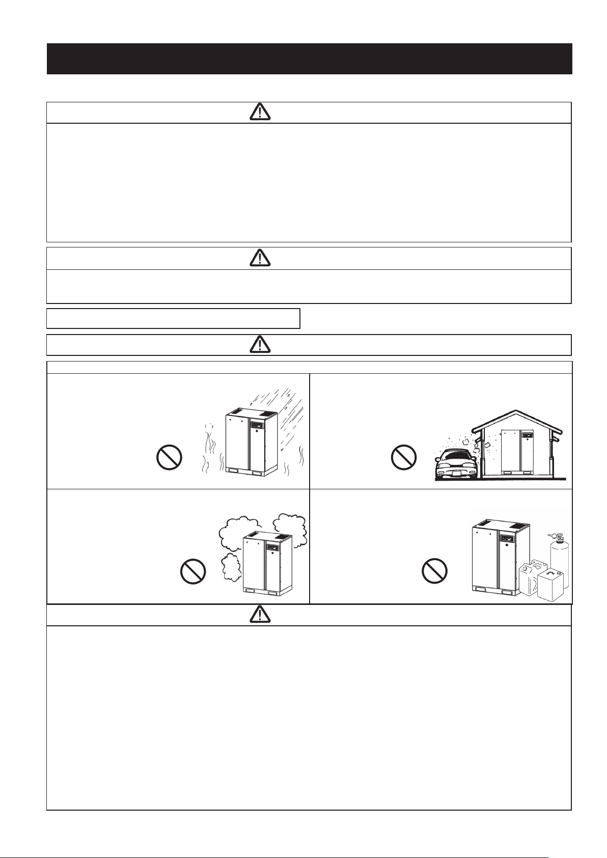
Avoid installing the air compressor in the dangerous areas described below:
● Avoid places subject to rain, water and/or high humidity.
Failure to adhere to this precaution
may cause electric current leakage,
rust and/or reduction in air compressor
life.
● Avoid outdoor installation or areas
subject to direct sunlight.
Failure to adhere to this
precaution may cause air
compressor overheating,
discoloration, alteration
and/or deterioration.
● Avoid areas subject to foreign matter, such as: iron powder,
sand dust, powdered dust, wood chips, textile waste, stone
powder, and fine iron powder fumes.
Failure to adhere to this precaution
may cause premature clogging of
the air filter and aftercooler fins,
excessive temperature rise,
air compressor
damage and
reduction in life
and/or explosive
accidents.
● Avoid areas where corrosive gases are present, such as:
organic solvents (benzene, toluene, etc.), acid, chloride gas,
ozone gas, ammonia, significant oil mists
and/or bromine.
Failure to adhere to this precaution may
cause rust to the air compressor components
and/or reduction in air compressor life.
● Avoid areas of close proximity to explosives and/or flammable
gases, such as: acetylene, propane gas, organic solvents,
explosive powdered dust and/or fire.
Failure to adhere to this precaution
may cause accidents.
Safety Precautions (continued)
S-2
Items requiring extra safety attention are described below. Observe the items described below, as well
as other items in the instruction manual that require safety attention.
● Do not use the air compressor to compress any gas other than air.
Using the air compressor to compress any gas other than air may lead to damage of the air compressor.
● SRL air compressors are not designed, intended or approved for breathing air applications. Hitachi does
not approve specialized equipment for breathing air applications and assumes no responsiblity or liability
for compressors used for breathing air services.
● If the scroll air compressor is used for any important production equipment, it is highly recommended to
utilize a back up air compressor.
A back up air compressor will keep production running in the event of a failure to an air compressor.
● Oil, dust and abrasive powder may be present in the air, and can be ingested into the air compressor
and mixed into the compressed air discharge.
Installation Safety Precautions
● Make sure that the installation ares has sufficient space for ventilation cooling. The compressor should
operate at room temperature in between 32 ゜ F and 104° F. If the room temperature exceeds104° F,
the air compressor's protective devices will stop compressor operation.
Excessive temperatures may lead to reduction in bearing life, seal life and seizure of the scroll head.
● Do not install the air compressors in a high location where the air compressor or air compressor parts
can be dropped.
● Install a pressure tight, heat resistant rubber hose at the compressed air discharge.
Do not use improper rubber hose or flexible tubing as they may crack and/or break.
● Verify that the power supply is 208/230/460 volt, 3 phase, 60 Hertz.
Failure to adhere to this precaution may cause motor and/or start failure.
● Do not install heavy objects, such as a filter, directly on the compressed air discharge.
Installing heavy objects on the compressed air discharge can cause damage to the piping and/or an accident.
WARNING
CAUTION
CAUTION
WARNING
Prohibition Prohibition
Prohibition
Prohibition

Safety Precautions (continued)
S-3
● If the Compressor Operation light is lit, keep all human body parts away from the rotating parts (pulley,
V-belt and ventilating fan) of the air compressor, as the air compressor will automatically start when
pressure drops.
Failure to adhere to this precaution may cause injury and/or accidents.
● Do not touch the air piping and check valve inside the air compressor package during operation and
immediately after the air compressor has stopped, as they will generate excessive heat.
Failure to adhere to this precaution may cause burns.
● Do not operate the air compressor with an inverter and/or generator.
Failure to adhere to this precaution may cause damage to the air compressor and/or accidents.
● Make sure to ground (earth) the air compressor.
Failure to adhere to this precaution may cause electric shock and/or injury.
● Remove all the transport fixtures prior to operation. (7.7/11kW : 2 locations, 16.5kW : 3 locations)
Failure to adhere to this precaution may cause excessive vibration and/or damage to the air compressor.
● Turn off the power supply during a power failure and/or electric storm.
Failure to adhere to this precaution may cause damage to the air compressor and/or accidents.
Operation Safety Precautions
WARNING
CAUTION
Maintenance and Inspection Safety Precautions
● Carry out the standard scheduled maintenance and service (See page 21).
Failure to adhere to this precaution may cause damage to the air compressor and/or accidents.
● Before performing any maintenance and/or inspection, ensure that the power supply has been
disconnected and all compressed air in the air receiver and air compressor piping has been released.
Failure to adhere to this precaution may cause electric shock and/or injury.
【122PSIG Model】
● Contact the local Hitachi distributor for the completion of the maintenance required every 10,000
hours or every 4 years of standard use. The maintenance has to be completed in this period, or earlier
depending on the operating environment. Do not operate beyond the scheduled period.
Failure to adhere to this precaution may cause damage to the air compressor and/or accidents.
For more details, contact the local Hitachi distributor.
【145PSIG Model】
● Contact the local Hitachi distributor for the completion of the maintenance required every 5,000 hours
or every 2 years of standard use. The maintenance has to be completed in this period, or earlier
depending on the operating environment. Do not operate beyond the scheduled period.
Failure to adhere to this precaution may cause damage to the air compressor and/or accidents.
For more details, contact the local Hitachi distributor.
【122PSIG Model】
● Contact the local Hitachi distributor for the completion of the overhaul required every 20,000 hours or
every 8 years of standard use. The overhaul has to be completed in this period, or earlier depending on
the operating environment. Do not operate beyond the scheduled period.
Failure to adhere to this precaution may cause damage to the air compressor and/or accidents.
For more details, contact the local Hitachi distributor.
【145PSIG Model】
● Contact the local Hitachi distributor for the completion of the overhaul required every 10,000 hours or
every 4 years of standard use. The overhaul has to be completed in this period, or earlier depending on
the operating environment. Do not operate beyond the scheduled period.
Failure to adhere to this precaution may cause damage to the air compressor and/or accidents.
For more details, contact the local Hitachi distributor.
● For maintenance and service inspections, please contact the local Hitachi distributor.
● Do not remove or modify the safety devices and/or insulating parts of the air compressor.
Failure to adhere to this precaution may cause damage to the air compressor and/or accidents.
● Use genuine HITACHI parts when maintaining or servicing the air compressor.
Failure to adhere to this precaution may cause damage to the air compressor and/or accidents.
● Do not use the air receiver if it has developed a leak. Do not attempt to repair or rework a leaking air
receiver.
Failure to adhere to this precaution may cause personal injury, damage to the air compressor and/or pressurized
rupture.
WARNING

Introduction
The instruction manual gives details related to the specifications, construction, installation, operation,
maintenance and inspection of the Oilfree Scroll Air Compressor.
This instruction manual describes the proper operation method to smoothly and safely utilize the
functions of the Oilfree Scroll Air Compressor.
Table of Contents
1
● Daily Operating Components
● Installation
1. Product Confirmation
2. Transporting the Air compressor
3. Installing the Air compressor
4. Piping the Air compressor
5. Wiring the Air compressor
● Operation
1. Control Panel Descriptions
2. Prior to Operation
3. Start Up
4. Daily Operation
● Maintenance and Inspection
● Troubleshooting
● Parts List
● Wiring Diagram
● Standard Specifications
● Aftermarket Ordering Procedure
・・・・・・・・・・ 2
・・・・・・・・・・ 4
・・・・・・・・・・ 4
・・・・・・・・・・ 4
・・・・・・・・・・ 5
・・・・・・・・・・ 7
・・・・・・・・・・ 8
・・・・・・・・・・ 12
・・・・・・・・・・ 12
・・・・・・・・・・ 14
・・・・・・・・・・ 19
・・・・・・・・・・ 20
・・・・・・・・・・ 21
・・・・・・・・・・ 29
・・・・・・・・・・ 33
・・・・・・・・・・ 34
・・・・・・・・・・ 36
・・・・・・・・・・ 37
Safety Precautions (continued)
● If the air compressor has not run in over one (1) month, carry out the long term storage operation
prior to restarting the air compressor (See page 28).
Failure to adhere to this precaution may cause abnormal wear to the air compressor components, damage to the air
compressor and/or accidents.
● Verify that the front door chain has been connected before closing the door.
● Make sure the V-belt is tightened properly prior to operation. If the V-belt is loose, tighten the V-belt
prior to operation.
Failure to adhere to this precaution may cause belt slippage, damage to the air compressor and/or excessive noise.
CAUTION

Daily Operating Components
2
Air Compressor Exterior
● Do not leave the front door open during operation.
Failure to adhere to this precaution may cause dust to be ingested, excessive vibration and/or noise to be
generated and/or reduction in air compressor life due to excessive temperature rise.
CAUTION
Air Exhaust
Air Intake
● Intake air and cooling
air is supplied to the air
compressor.
Compressed Air
Discharge Pipe
Power Cable Inlet
Control Panel
Locks for door
enclosure with Keys
Front Door
Emergency Stop
Switch
SRL-7.5M6LL/ML/LH/MH
SRL-11M6LL/ML/LH/MH
SRL-16.5M6LL/ML/LH/MH
● Make sure that front
door is closed during
the operation of the air
compressor.
Air Exhaust
Air Intake
● Intake air and cooling
air is supplied to the air
compressor.
Compressed Air
Discharge Pipe
Power Cable Inlet
Control Panel
Locks for door
enclosure with Keys
Front Door
Emergency Stop
Switch
● Make sure that front
door is closed during
the operation of the air
compressor.

Daily Operating Components(continued)
3
Air Compressor Interior
Check Valve
Scroll Head
Air Release Valve
Power Supply Panel
Electric Main Motor
Rubber Vibration
Isolators
V-BeltPrimary Cooler
Ventilating Fan
SRL-7.5M6LL/ML/LH/MH
SRL-11M6LL/ML/LH/MH
SRL-16.5M6LL/ML/LH/MH
Safety Relief Valve
Rubber Hose
Intake Air Filter
● 10HP (7.7kW) : 3 locations
● 15HP (11kW) : 4 locations
Transport Fixture
● 2 locations
Secondary Cooler
Main Power Supply
Terminal Block
Electromagnetic
Contactor
Check Valve
Scroll Head
Air Release Valve
Power Supply Panel
Electric Main Motor
Rubber Vibration
Isolators
V-Belt
Primary Cooler
Ventilating Fan
Safety Relief Valve
Rubber Hose
Intake Air Filter
● 6 locations
Transport Fixture
● 3 locations
Secondary Cooler
Main Power Supply
Terminal Block
Electromagnetic
Contactor
Ventilating Fan

Installation
4
● It is recommended that properly trained personnel move the air compressor.
● Operation of the air compressor with the transport fixtures installed will lead to excessive vibration
of the air compressor and the package may rupture. The transport fixtures must be removed prior
to operation of the air compressor.
WARNING
1 Product Confirmation
1. Check the air compressor nameplate to verify that
the proper model air compressor was delivered.
2. Verify that there has been no damage to the air
compressor during transportation.
3. Verify that the items shown below are included
with the air compressor.
Rubber
vibration
sheets for
installation -
4 Sheets
Instruction
Manual
1 copy
4 - Steel
plates
& 8 - Bolts
Model Nameplate
● Review the model
number, serial number,
power requirements and
compressor
specifications.
Warning Label
● Read the Warning Label
before use.
● Do not use an air compressor with
a power supply differing from the
specified power requirement.
Incorrect power supply may cause
fire and/or abnormal vibration.
CAUTION
2 Transporting the Air Compressor
Transporting the Air Compressor Removing the Transport Fixtures
Moving with a Forklift
P l a c e a bu f f e r pl a t e in
between the air compressor
and the forklif t to prote ct
the air compressor panels.
Do no t t i l t th e for k s o f
the forklift too much. Too
much tilt may cause the air
compressor to drop.
Remove the transport fixtures
Bolt
Fixture
Transport Fixtures Location
● After installing air compressor, please
be sure to attach the plates shown in
the figure to the right.
These plates are shipped with the
compressor and will greatly reduce
compressor noise during operation.
【Reference】
● Open the front door, remove the yellow bolts and
remove the transport fixtures prior to operating.
7.7/11kW : 2 locations
16.5kW : 3 locations

1. Install the air compressor inside a room with adequate space, ventilation and relatively low humidity.
2. Keep the operating room temperature in between 32° F and 104° F.
3. Install the air compressor with the recommended spacing shown in the figure below for ease of
maintenance and temperature control.
・The air compressor is designed to inhale air from the left side of the package and exhaust the air out
of the top of the package. It is recommended to provide suction and exhaust openings as shown in
the figure below to properly ventilate the room. If the suction and exhaust openings cannot be
provided, do not modify the air compressor without consulting the local Hitachi distributor.
4. The allotted space located to the right and to the rear of the air compressor must be maintained
to perform maintenance. Ensure that this space is maintained if the air compressor is going to be
permanently installed. (#)
A B
Installation(continued)
5
3 Installing the Air Compressor
Ventilating fan
● If the temperature exceeds 104° F in the
room, install a ventilating fan to keep the
room temperature below 104° F.
● Select a ventilating fan with more than
enough capacity to handle the air flow of
the room.
Maintenance Space,
Intake Air, Discharge
Piping and Wiring
● Secure enough space for proper ventilation.
● Absence of intake space causes the suction resistance to
increase, resulting in temperature rise in the package, which may
cause a reduction in the life of air compressor components.
● Secure enough space for wiring and piping.
Ventilation and
Exhaust Space
● Secure enough space for proper
ventilation.
● Absence of intake space causes
the suction resistance to increase,
resulting in temperature rise in the
package, which may cause a
reduction in the life of air
compressor components.
Maintenance Space for
Right & Rear Sides
● If a space of more than 12 in.
and/or 20 in. cannot be secured,
utilize a piping connection that
can be easily removed for
maintenance purposes.
Front Maintenance Space
● Secure the proper amount of
space to open the front door of
the air compressor for inspection.
Exhaust duct
● Do not directly connect the duct with the
air compressor. The ducting hood should
maintain a distance (indicated as “h”)
between the air compressor and the duct
that is larger than the diameter of the duct.
h
Exhaust
air
40 in. or more
Exhaust
Opening
Intake
Opening
Exhaust
air
I
ntake
air
I
ntake
air
12 in.
or more (#)
20 in.
or more (#)
Exhaust
air
40 in. or more
25 in. or more
Intake Opening
● The intake opening should be installed as
low as possible. The area of the opening
should be calculated as 1,550 sq in.(1m
2
)
per compressor1.
● Conditions of the ambient air, including
dust and toxic substances, should be
considered when selecting the location
for the intake air opening.
【Reference】
■ Guidance for construction of ventilating fan and exhaust duct
Exhaust Air
Exhaust Air
of air
compressor
Intake Air
■ Ventilating Fan
Refer to the v olu me of
necessary ventilation (1).
Intake Air
Ex h a u s t
Duct
■ Ventilating Fan
Refer to the v olu me of
necessary ventilation (2).

5. Install the Air Compressor on Level Ground with a Sufficient
Weight Load. If there is a gap between the air compressor
and the ground, adjust the gap with the attached rubber
vibration isolators to eliminate the gap.
6. For parallel operation, install the air compressors as shown
in the figure to the right. If the air compressors cannot be
installed as shown in the figure to the right, install in a way
that prevents the exhaust of one air compressor from
entering the air intake of the other air compressor.
Installation(continued)
6
● Keep the ambient room temperature in between 32° F and 104° F. If the temperature exceeds
104° F or there is a defect in the installation, the air compressor protective devices may stop air
compressor operation and/or damage or reduction in compressor life may occur.
● The air compressor discharges air exhaust from the top. Make sure that there are no items such as
lights, or wirings that are above the air compressor and can be affected by the exhaust air.
● Do not modify the intake or exhaust of the air compressor package, otherwise the temperature may
become unbalanced, resulting in the protective devices of the air compressor to function improperly.
● Do not install ducting on the intake or the exhaust of the Oilfree Scroll Air Compressor, as it may
cause damage to the air compressor.
● Do not install the air compressor in an area above the ground, as the air compressor and/or parts
of the air compressor may fall.
WARNING
● Do not install the air compressor on ground with
insufficient weight load. Do not operate the air
compressor attached to a pallet or packaging table.
● Do not install on any type of rubber other than the
attached rubber vibration isolators and do not bolt to
the concrete. This may result in excessive vibration
and/or damage to the air compressor.
WARNING
SRL-7.5M6LL
SRL-7.5M6ML
SRL-7.5M6L
H
SRL-7.5M6MH
SRL-11M6LL
SRL-11M6ML
SRL-11M6L
H
SRL-11M6MH
SRL-16.5M6LL
SRL-16.5M6ML
SRL-16.5M6L
H
SRL-16.5M6
MH
Generate Heat kJ/h
25,116 36,000 54,000
Cooling Air Flow CFM (㎥/min) 990 (28) 1,240 (35) 1,520 (43)
Cooling Air Differential Temperature
° F (℃ )
63 (35) 63 (35) 63 (35)
Required ventilating capacity (1)
CFM (㎥/min)
2,472 (70) 3,532 (100) 5,297 (150)
Required ventilating capacity (2)
CFM (㎥/min)
777 (22) 1,130 (32) 1,695 (48)
【Please see the table to the below for Reference】
■ Generated Heat & Required Ventilating Capacity Table
The required ventilating capacity value is the required capacity to keep the temperature rise in the room
within 9° F (5℃ ) when only one Oilfree Scroll Air Compressor is operating.
Item
Model
Install the Air Compressor
on Le v el Gro und with a
Sufficient Weight Load.
Rubber vibration
isolators
Exhaust air
Exhaust air
Intake air
Intake air
39 in. or more

1. Ensure that a properly sized air receiver is installed (80 gallons or more). Without a properly sized air
receiver it is possible that the air compressor can be damaged due to excessive starts and stops.
2. Use a textile reinforced, heat resistant rubber hose (hydraulic) of appropriate rating to connect the
Oilfree Scroll Air Compressor to the plant air system piping.
■ It is necessary to install a properly sized air receiver to this compressor in order to reduce excessive
starts and stops.
■ Without a properly sized air receiver, it is possible that the main motor or electromagnetic contactor may
receive unwarranted wear due to excessive starts and stops.
7
● Use a heat resistant, pressure tight rubber hose to connect the Oilfree Scroll Air Compressor to the
plant air system piping. The rubber hose will prevent damage to the plant air system piping due to
vibration.
● Use of an improper rubber hose may lead to cracks and/or leaks due to hose deterioration.
● Do not operate the air compressor when the stop valve between the air receiver and the air
compressor is closed.
● Do not install heavy objects, such as drain traps and filters, to the compressed air discharge as they
may damage the discharge line of the air compressor.
● If a remote vertical air receiver is installed, it is recommended to attach the air receiver to the ground
with foundation bolts.
WARNING
4 Piping the Air Compressor
Safety Relief Valve
● If a stop valve is installed
in the middle of the
compressed air piping,
install a safety relief valve
between the air
compressor and the stop
valve.
Vertical Air Receiver
● To avoid damage to the air
compressor due to excessive
starts and stops, a properly sized
air receiver must be installed.
Hose Fitting
Rubber Hose
● Use an appropriate
rubber hose to connect
with the equipment.
Stop Valve
● Make sure to install a
stop valve between the air
compressor and the air
receiver.
Installation(continued)
● Without a properly sized air receiver, it is possible that a serious accident may occur due to the
unwarranted wear of the main motor or electromagnetic contactor.
● For the protection of the air compressor, if excessive starts and stops occur the compressor will
shut off and display : cycle error [E.CY]. This will stop the supply of compressed air.
● The error message cycle error [E.CY] is an indication that the volume of air receiver is insufficient
for proper operation. An increase in the volume of the air receiver will eliminate the cycle error [E.CY].
WARNING

1. Carry out the electrical work according the local and
national electric codes and standards.
2. Connect the power supply for the main motor through
an earth leakage (ground) circuit breaker between the
main power and the Oilfree Scroll Air Compressor.
3. Wiring capacities are as follows.
1. Internal air compressor wiring has been
completed prior to shipment from the
factory.
2. Remove the front panel, open the door
to the power supply panel and connect
the main power supply cable to the
terminal block.
Installation(continued)
8
● Verify that the power supply for the facility corresponds with the power supply of the air
compressor.
Failure to adhere to this precaution may lead to starting failure, electric motor failure and/or damage to the air
compressor.
● The SRL air compressor should be wired per the local and national electric codes. Improper wiring
may lead to excessive voltage drops.
● Do not use a generator.
CAUTION
5 Wiring the Air Compressor
Connecting the Main Power
Model Power
Wiring Capacity
Minimum Wire Thickness
(mm/AWG)
Minimum Ground Line Wire
Thickness
(mm/AWG)
Circuit Breaker
Capacity
(A)
Fuse
Capacity
(A)
SRL-7.5M6LL
SRL-7.5M6LH
208/230V
3 Phase
60 Hertz
3.9/AWG8 3.9/AWG8 75 75
SRL-11M6LL
SRL-11M6LH
4.9/AWG6 4.9/AWG6 100 100
SRL-16.5M6LL
SRL-16.5M6LH
6.8/AWG4 6.8/AWG4 100 100
SRL-7.5M6ML
SRL-7.5M6MH
460V
3 Phase
60 Hertz
3.9/AWG8 3.9/AWG8 40 40
SRL-11M6ML
SRL-11M6MH
4.9/AWG6 4.9/AWG6 50 50
SRL-16.5M6ML
SRL-16.5M6MH
6.8/AWG4 6.8/AWG4 50 50
Wiring the Air Compressor
Terminal
Block
Main Power
Supply Cable
Ti g h ten th e n u t a f t er
conn e c t i n g th e po w e r
cable.
Note) 1. Use a UL489 listed circuit breaker or UL listed dual-element time delay branch circuit type fuses.
2. The Circuit Breaker and Fuse capacity depend on "UL standard".
Earth Leakage (Ground)
Circuit Breaker
Front panel

3. Make sure to ground the air compressor.
4. For AC208/230V models, the air compressor ships
wired for AC230V, to operate the air compressor at
AC208V, reconnect the wiring of the transformer
primary to the 208V terminal.
5. Turn ON the circuit breakers and motor breakers.
6. Turn on the main power to verify that the voltage
is the specified voltage and phase.
7. Press the start button to verify that the compressor
operates during a trial run. If [E.rE] is indicated on
the digital display, the air compressor is in a reverse
phase condition. To fix the problem, turn off the main
power and reconnect the power after switching two
of three wires of the main power. If nothing has
changed after reconnecting, please refer to P.29.
8. If the air compressor is rotating correctly, the cooling
air flows as shown in the figure to the right.
9
● Make sure to turn off the main power supply before carrying out any wire connections.
● Firmly tighten the screws connecting the main power wiring to the air compressor.
Loose wires may lead to excessive overheating and/or accidents.
CAUTION
Bolts
Terminal Block
Switch two of
the three wires.
Exhaust
Intake
230V
208V
Recon n e c t
the wiring
Do not
reconnect
the wiring
Transformer
Installation(continued)
ON
Ground
Terminal
Circuit Breaker Motor Breaker
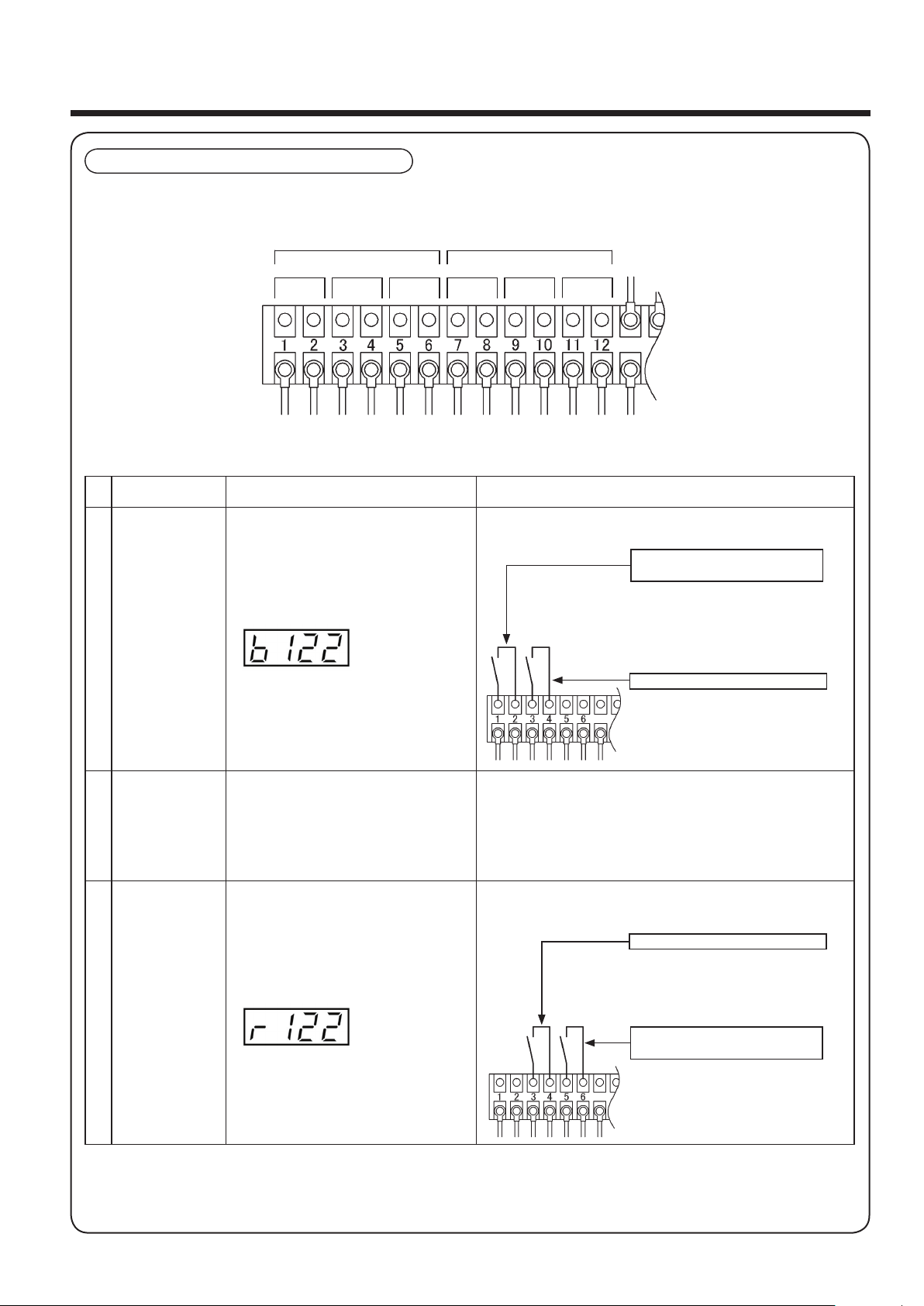
The following input and output signals terminal block is equipped in the power supply control panel.
No.
Terminal
Description
Content How to use
①
Customer Control
Run Change-over
Signal
When u ti lizing custom er control ru n,
connect this to the external terminals
of the cu stomer’ s controll er. When
controlled by a customer’s controller,
"b " will be indicat e d on the digital
display. (Only pressure switch control
mode is allowed.)
The input signal is approximately 5VDC, 10mA. Use a switch
or a relay contact with the minimum applicable load of this
value.
②
Remote Operation
Command Signal
Under remote operation, the operation
of t he ai r c ompr e s sor is c ontr o l led
by the input si gnal fro m the remot e
switch. Under customer control run,
the operation of the air compressor is
controlled by the input signal from the
control panel of the customer.
③
Remote Operation
C h a n g e - o v e r
Signal
Before the remote operation of the air
compressor can be used, the operation
switch must be activated. If the mode
of t he air compresso r is changed to
remote operation a change-over signal
wi ll occur . A charac ter “r” (R emot e
mo de) is dis played on t he left mos t
position of the digital display.
When remote control is to be used, the
remote operation change-over signal
must occur before activating the remote
operation command signal.
The input signal is approximately 5VDC, 10mA. Use a switch
or a relay contact with the minimum applicable load of this
value.
Installation(continued)
10
Remote Input and Output Signals
Customer Control Run
Change-over Switch
Inst a l l th e cu s t o m e r co n t r o l ru n
ch a n g e - o v e r sw i t c h near the ai r
compressor.
Sw i t c h ON : Cu s t o mer contr o l l ed
operation is running.
Swi t c h OF F : Lo c al o p e r a t i on i s
running.
① ②
③ ④ ⑤
⑥
# Input Signals Output Signals
# Use shielded wires as input signal wires.
Remote Operation & Stop Switch
Ins tall the remote o pe ration & stop
switch for remote control.
Switch ON : Compressor is running.
S w i t c h OF F : C o m p re s s o r ha s
stopped.
Remote Operation & Stop Switch
Ins tall the remote o pe ration & stop
switch for remote control.
Switch ON : Compressor is running.
S w i t c h OF F : C o m p re s s o r ha s
stopped.
Remote Operation Change-over
Switch
Install the remote operation changeover switch near the air compressor.
Sw i t c h ON : Remo t e opera t i o n is
running.
Swi t c h OF F : Lo c al o p e r a t i on i s
running.

Caution Note: The “Customer Control Run mode ( ① )” and “Remote Operation mode ( ③ )” cannot be
used at the same time.
(#) Compressor Head Error
This unit has a back-up function that will allow the unit to continue operating even if one compressor
head breaks down. If there is an error on one compressor head, the error signal will come ON and the
operation of other compressor head(s) will continue.
No.
Terminal
Description
Content How to use
④ Operation Signal
Th i s signal is out p u tted when the
operation is ON.
The output is a non-voltage signal. The load connected
should be 250VAC/30VDC, 5A or less and should use an
auxiliary relay of small load.
⑤ Error Signal
Th i s signal is out p u tted when the
errors occur and the air compressor
cannot be restarted.
⑥ Alarm Signal
This signal is outputted when an alarm,
such as a maintenance alarm, occurs.
Installation(continued)
11
● When carrying out the wiring connection for the terminal block, make sure to turn off the main
power supply.
CAUTION

● If an error during start up occurs, please contact the local Hitachi distributor.
Digital Display (Yellow)
Indicates:
1) Discharge Pressure
2) Total Running Hours
3) Alarm/Errors (if applicable)
If the digital display is lit, main
power to the air compressor is ON.
Operation
12
1 Control Panel Descriptions
Control Panel
Screen Shift Switch
Toggles the digital display from
discharge pressure and total
running hours for three seconds.
Maintenance Alarm Light (Red)
Lights up to inform operating
personnel that maintenance is
required based on hours of operation.
Start and Stop Switch
Pressing these switches starts and stops the
air compressor, respectively.
Compressor Operation Light (Green)
Lights up during compressor operation.
● If nothing displays in the digital display, even with power on, either the emergency stop switch is
operating or the circuit breaker in the UL power supply panel is OFF. Always turn off the power
supply prior to inspection.
CAUTION
Indication Light (Red)
Control Mode Switch
Press this switch to select the
proper control mode.

Operation (continued)
Total Operating Time of the Scroll Head 3
Lower Compressor head is indicated by [ Co. ] and operating time flashes alternately.
Discharge Pressure Indication
【Screen Shift Switch Operation】
The total operation time of the unit and each compressor head is indicated. Press the switch and the
display will change as indicated in the diagram below. The total operation time of the unit or each
compressor head will only be displayed for 3 seconds, and then the discharge pressure will be displayed.
Press Screen Shift Switch Once
Pressing the Screen Shift Switch once will show the total operating hours of the air compressor for three
seconds.
Note : The air compressor total operating hours can be used as a guide for scheduling maintenance for: the air
intake filter, V-belt, and other normal inspection/maintenance items.
Press Screen Shift Switch Again Within Three Seconds
Pressing the Screen Shift Switch again within three seconds will show the total operating hours of the
Scroll Head for three seconds.
Note : Displays the total operating hours of the scroll head only.
Use these displays as a guide for maintenance schedule.
Note : The total operating hours indicated on the digital display is the total operating hours in multiples of ten
(for example : 155 on the digital display = 1,550 total operating hours).
Total Operating Time of the Scroll Head 1
Upper Compressor head is indicated by [ Co. ] and operating time flashes alternately.
Total Operating Time of the Scroll Head 2
Middle Compressor head is indicated by [ Co. ] and operating time flashes alternately.
Total Operating Time of the Air Compressor
After 3 seconds
13

● This section details the operation, activation and control methods of the SRL air compressor.
It is possible to select the operation control mode of the air compressor, change the control pressure
settings and set the automatic recovery from power failure. It is recommended that the selection of the
appropriate settings be selected based on the conditions in which the compressor will be used.
(In the case that “Customer Control Run mode” is selected, only the pressure switch control mode will
be available.)
1. Operation Control Mode Setting
It is possible to change between Multi-Drive control mode and pressure switch control mode.
The operation of the air compressor can be controlled as followed.
(1) Multi-Drive Control Mode (Energy Saving mode)
Responding to the need of compressed air, the operation of SRL compressor heads is modified
automatically to keep the delivery pressure at around the necessary pressure (recovery pressure). This
operation allows the compressor to save energy by avoiding useless operation of compressor heads.
(2) Pressure Switch Control Mode
The operation of SRL compressor heads is controlled by Pressure Switch Control Mode. The operation
of all SRL compressor heads are stopped simultaneously when the unit stops operating.
When starting the unit, the operation of each SRL compressor head starts one after another in
approximately 1.5 second increments to reduce the starting load.
Operation (continued)
14
2 Prior to Operation
How to select the control mode
Press the "Control Mode Switch" when the main power in ON and while the air compressor is not
running. The operation control mode will be changed as follows when you press the switch.
M u l t i - D r i v e
Control Mode
Pressure Switch
Control Mode
Pressure Switch
Control
Multi Drive Control
Maximum
Pressure
Recovery
Pressure
122
118
114
110
Pressure 【 psig 】
3 heads 1 head 2 heads 1 head 2 heads
2
heads

2. Changing the Pressure Settings
The control pressure can be changed with the
switches shown below on the control panel.
An energy saving operation can be performed to
lower wasted energy by lowering the maximum (stop)
pressure. The normal pressure settings of the air
compressor are shown in the figure to the right.
Under the Muti-Drive control mode, the delivery
pressure is to be above the “recovery pressure +
12/15psig”, and will not reach the maximum setting
pressure normally. Under Multi-Drive control mode,
more energy savings is possible by lowering the
recovery pressure.
■ Procedure for changing the control pressure setting
Press the "Stop" switch, and drop the pressure in the air receiver to 70psig or lower (it is impossible to
change the control pressure setting if the pressure in the air receiver is above 71psig). Once the
pressure in the air receiver is below 70psig the control pressure setting can be changed by following
the procedure below.
15
Operation (continued)
Pressure Setting
122PSIG Model 145PSIG Model
Maximum (Stop)
Pressure (psig)
122 145
Recovery (Start)
Pressure (psig)
110 115
EX. 122PSIG Model
Digital Display
Steps
5 & 6
Steps
2, 3 & 4
Steps
2 & 4
Steps Digital display
1
Verify that the pressure is indicated on the digital display.
2
Press the stop switch and then press the start switch and hold both buttons for 5
seconds to change the indication on the digital display to PC.
3
To change the maximum (stop) pressure, press the start switch. The indication on the
digital display changes to H122 (this is an example of what the indication on the digital
display will be for the pressure settings from the factory).
4
Pressing the stop switch will lower the maximum pressure setting by 1 PSIG.
Pressing the start switch will raise the maximum pressure setting by 1 PSIG.
5
After the change in pressure setting has been set, press the Screen Shift switch
and the digital display indication will change to PC.
6
Pressing the Screen Shift switch again will change the digital display indication to the
pressure display.
To change the recovery (start) pressure, press the stop switch in steps 3 above to change
the digital display indication to L110 (this is an example of what the indication on the digital
display will be for the pressure settings from the factory) and then change the pressure
settings as shown in steps 4 and later.

■ Cycle Control Logic (CCL): Operation and protection from excessive cycling of the main motors
● The SRL air compressor measures the "ON-OFF cycle number" after the pressure settings have been
changed and automatically adjusts the maximum (stop) pressure to prevent the "ON-OFF cycle" from
increasing when the "ON-OFF cycle number" increases exponentially, thus protecting the scroll head,
electric motor and electromagnetic contactor (Please see the figure below).
● After the CCL adjusts the maximum (stop) pressure, the CCL continues to automatically measure the
"ON-OFF cycle number" and lower the maximum (stop) pressure within the permissible range of the
"ON-OFF cycle number", until the CCL nears the set maximum (stop) pressure of the air compressor
and the "ON-OFF cycle number" becomes consistent.
● A protection device is equipped on this unit to prevent frequent ON-OFF operations. Start Frequency
Protection automatically measures cycles of ON-OFF, and in the case that the cycle of ON-OFF is less
than 20 seconds, the operation will continued for 20 seconds even if the maximum pressure setting is
lowered. In the event that it takes less than 20 seconds to reach the standard maximum pressure
(122psig/145psig) the controller will stop the operation of the air compressor at 122psig/145psig.
If this happens 5 times continuously, it is defined as a「ON-OFF cycle error」. If this occurs「E.CY」
will be indicated on the digital display, and the operation of the air compressor will stop to protect the
compressor head, electric motors and electromagnetic contactor.
● Pressing the Stop switch will reset the unit from the「ON-OFF cycle error」, and allow it to restart the
operation of the air compressor. However, if the situation which caused the「ON-OFF cycle error」 is
not eliminated, the「ON-OFF cycle error」 will occur again.
● To lower the amount of cycles of ON-OFF the recovery pressure will need to be lowered by following
the procedure for changing the control pressure setting. (Refer to P.15)
If the recovery pressure is already set at its lowest point, a larger air receiver will need to be installed.
16
Operation (continued)
■ Changeable Pressure Ranges
122 PSIG Model
Pressure
Description
Maximum (Stop)
Pressure (psig)
Recovery (Start)
Pressure (psig)
Pressure
Bandwidth (psig)
Pressure Unit
Interval of Change
Standard Pressure 122 110 12 -
Changeable
Pressure Range
122 - 92 110 - 80 12 1
145 PSIG Model
Pressure
Description
Maximum (Stop)
Pressure (psig)
Recovery (Start)
Pressure (psig)
Pressure
Bandwidth (psig)
Pressure Unit
Interval of Change
Standard Pressure 145 115 30 -
Changeable
Pressure Range
145 - 95 130 - 80 15 1
Notes: 1. When operating the air compressor with a pressure bandwidth of 30 psig it is recommended that a large size vertical air receiver
is installed.
2. The pressure bandwidth of the maximum pressure and the recovery pressure cannot be lower than 12/15psig. The interval of
pressure change is 1psig.
3. The air compressor may keep running over the maximum pressure of 122psig/145psig because of the Start Frequency
Protection even if the maximum pressure is lowered.

17
Operation (continued)
Once 2nd 3rd 4th 5th
20sec.
or less
20sec.
or less
20sec.
or less
20sec.
or less
20sec.
or less
20sec.
or more
20sec.
20sec.
Start Frequency
Being Measured
"ON-OFF cycle error"
occurs
ON-OFF
cycle
Extend ON-OFF
cycle
[STOP]
[START]
Standard
Maximum
Pressure
(122psig/145psig)
Standard
Recovery
Pressure
(110psig/115psig)
T h e m a x i m u m
( S t o p ) P r e s s u r e
setting has been
c h a n g e d o n t h e
control panel of the
air compressor.
The recovery (Start)
Pr e s su r e se t t i ng
has been changed
o n t h e c o n t r o l
p a n e l o f t h e ai r
compressor.
● As the protection device extends the ON-OFF cycle, the discharge pressure may exceed the setting
maximum pressure. This is not an error.
CAUTION

Automatic recovery from power failure does not function under default setting.
It is possible to set automatic recovery from power failure by operation on the control panel.
Operate the switches on the control panel as shown below in order to automatically recover from power
failure.
18
Operation (continued)
● When operating in automatic power recovery, the operation of the air compressor will start
automatically when the main power supply returns. Make sure to press the Stop switch before turning
off the main power supply when conducting maintenance.
● In the case of a power failure, turn off the main power supply. Be aware that residual pressure may
exist even though there is not a digital display.
● When restarting the operation of the air compressor turn on the main power supply and verify the
operation control mode before pressing the Start switch.
WARNING
Digital Display Start Switch Stop Switch
Steps Digital Display
1 Verify if the pressure is indicated on the digital display.
2
Press the stop switch continuously for three seconds.
"P-0" is indicated on the digital display.
3
Press the start switch until "P-1" is indicated on the digital dispiay and
power failure automatic recovery is set.
4
To cancel the power failure automatic recovery, carry out steps 1 to 3
to indicate "P-1" to "P-0" on the digital display.
5 Pressure is again indicated on the digital display after three seconds.
NOTE: Even if the power failure automatic recovery has not been set, the pressure indication will
return to the digital display after three seconds.

Operation(continued)
● During inspection of the safety relief valve, a loud noise will be emitted from the safety relief valve,
therefore, prepare for the noise in order to prevent personal injury.
● If there is excessive vibration or abnormal sound, please refer to page 25 for adjustment.
● If the air compressor is not operating and the discharge stop valve is closed, the pressure indication
on the digital display may lower, which is due to a decrease in temperature. This is normal.
● Turn off the power in the case of a power failure or electric storm to prevent damage to the air
compressor and/or personal injury.
① Close the front door and fully open the
discharge stop valve.
3 Start Up
(Please contact the local Hitachi distributor for start up.)
② Check the earth leakage (ground) circuit
breaker to make sure it is ON. Turn ON
the main power supply to the air
compressor.
⑦ Open the discharge stop valve to lower the
pressure and verify that the air compressor
restarts at the load pressure setting.
⑤ Close the stop valve on the air receiver
and verify that the operation of the air
compressor stops when the pressure
reaches maximum pressure (under
pressure switch control mode).
During operation of Multi-Drive control
mode, the SRL compressor heads will stop
one after another, and maximum pressure
will not be reached. This is not a failure.
⑥ Slightly pull the spindle of the safety relief valve
when the air compressor is near maximum
pressure.
Safety Relief
Valve
ON
CAUTION
Slightly pull the spindle of
the safety relief valve.
19
③ Press the Start switch.
④ Verify that the rotating direction of the
main electric motor is clockwise when
viewed from the front as shown in the
diagram below.
Rotating
Direction
7.5/11M6 16.5M6
Note) It is normal that the operation of the
air compressor restarts at a pressure
higher than the recovery pressure under
Multi-Drive control mode.

■
Start
① Completely open the stop valve on the air receiver.
② Verify that the earth leakage (ground) circuit breaker is ON.
③ Turn ON the main power supply.
④ Select appropriate operation control mode of the air compressor.
⑤ Press the Start switch.
⑥ Automatic operation turns ON.
■ Stop
① Press the Stop switch.
② Completely open the vertical air receiver stop valve to remove the residual pressure and depressurize
the system to 0 psig.
③ Turn OFF the main power.
● Since the air compressor has the capacity to automatically start and stop when the Start switch has
been pressed, press the Stop switch and turn off the main power supply prior to inspecting the inside
of the air compressor.
● If the ambient temperature is above 104° F, the pressure indicated on the digital display may not read
0 psig, even if the air receiver has been de-pressurized. Ventilate to lower the ambient temperature.
● In the case of a power failure and/or electric storm, ensure that the main power supply has been
turned off. Pay attention that residual pressure may exist since there is no digital display.
Operation(continued)
4 Daily Operation
● Do not operate a damaged and/or improperly activated air compressor.
● Do not put any human body parts near the rotating parts of the air compressor during operation, as
they may become entangled and result in a serious injury. Take note that the air compressor has the
capability to automatically restart without notice.
● Do not touch the discharge piping in the front of the scroll head or the air piping leading to the air
receiver and the check valve, as they reach excessively high temperatures during operation and
immediately after the air compressor has stopped. Failure to adhere to this precaution may lead to
burns.
WARNING
CAUTION
20

■ Daily inspections of the SRL air compressor are imperative to long safe operation. Review the total
operating hours on the control panel of the air compressor with the operation time schedule shown on
the table below and carry out the inspection at the proper time intervals.
■ Maintenance and inspection time interval indicates the time for maintenance and inspection, not the
guaranteed time of the air compressor or parts.
Component
Inspection
Instructions
Maintenance and Inspection Time Interval
Remarks
Daily
Every
500 Hours
or 2 Months
Every
2,500 Hours
or 1 Year
Every
5,000 Hours
or 2 Years
Every
10,000Hours
or 4 Years
Every
20,000Hours
or 8 Years
Air Receiver Tank
(Option)
Drain accumulated
condensate in air receiver.
○
Accumlation of dirt of
dust
Check or clean. ○
Complete Air
Compressor
Inspect for excessive
noise and vibration.
○ Refer to page 25.
Safety Relief Valve Inspect operation. ○
Replace the safety relief
va l v e if th e r e is any
damage.
Pressure Sensor
Inspect operation and
pressure display confirm.
○
Replace the sensor if
there is any damage.
Check Valve
Inspect for leaks or
replace.
○ ●
Ventilating Fan
Inspect or replace
the ventilating fan.
○ ● Refer to page 26.
Bolts, Nuts & Screws
Inspect and tighten any
loose items.
○ Refer to page 26.
Intake Air Filter
Replace a dirty or
clogged filter.
○ ● ◎ Refer to page 26.
Sirocco Fan & Scroll
Fin
Clean the dirt off
these components.
○ ◎
Scroll Bearing
Grease or inspect
the bearing.
○ ◎
Replace the scroll head if
there is any damage with
bearing.
Tip Seal & Face Seal Replace the seals. ● ◎
Bearings Inspect the bearings. ○ ◎
Replace the scroll head if
there is any damage with
bearings.
Scroll Head
Replace the scroll
head.
●
Rubber Hose Inspect for leaks. ○ ●
Re p l ac e th e ru b b e r
hos e if th e r e is an y
damage.
V-Belts
I n s p e c t , ad j u s t a n d / o r
replace a loose or damage
v-belt
○ ● Refer to page 27.
Electromagnetic
Contactor
Inspect or replace. ○ ●
Rubber Vibration
Isolator Pads
Inspect for any damage
and/or hardness.
○
Rep l a c e th e pa d s if
there is any damage.
Electric Main Motor Inspect for any damage. ○
Re p lac e th e mo t or i f
there is any damage.
Coolers
Clean the dirt off or
replace.
○ ●
Maintenance and Inspection
【122PSIG Model】
21

Maintenance and Inspection (continued)
22
Component
Inspection
Instructions
Maintenance and Inspection Time Interval
Remarks
Daily
Every
500 Hours
or 2 Months
Every
2,500 Hours
or 1 Year
Every
5,000 Hours
or 2 Years
Every
10,000Hours
or 4 Years
Every
20,000Hours
or 8 Years
Air Receiver Tank
(Option)
Drain accumulated
condensate in air receiver.
○
Accumlation of dirt of
dust
Check or clean. ○
Complete Air
Compressor
Inspect for excessive
noise and vibration.
○ Refer to page 25.
Safety Relief Valve Inspect operation. ○
Replace the safety relief
va l v e if th e r e is any
damage.
Pressure Sensor
Inspect operation and
pressure display confirm.
○
Replace the sensor if
there is any damage.
Check Valve
Inspect for leaks or
replace.
○ ●
Ventilating Fan
Inspect or replace
the ventilating fan.
○ ● Refer to page 26.
Bolts, Nuts & Screws
Inspect and tighten any
loose items.
○ Refer to page 26.
Intake Air Filter
Replace a dirty or
clogged filter.
○ ● ◎ Refer to page 26.
Sirocco Fan & Scroll
Fin
Clean the dirt off
these components.
○ ◎
Scroll Bearing
Grease or inspect
the bearing.
○ ◎
Replace the scroll head if
there is any damage with
bearing.
Tip Seal & Face Seal Replace the seals. ● ◎
Bearings Inspect the bearings. ○ ◎
Replace the scroll head if
there is any damage with
bearings.
Scroll Head
Replace the scroll
head.
●
Rubber Hose Inspect for leaks. ○ ●
Re p l ac e th e ru b b e r
hos e if th e r e is an y
damage.
V-Belts
I n s p e c t , ad j u s t a n d / o r
replace a loose or damage
v-belt
○ ● Refer to page 27.
Electromagnetic
Contactor
Inspect or replace. ○ ●
Rubber Vibration
Isolator Pads
Inspect for any damage
and/or hardness.
○
Rep l a c e th e pa d s if
there is any damage.
Electric Main Motor Inspect for any damage. ○
Re p lac e th e mo t or i f
there is any damage.
Coolers
Clean the dirt off or
replace.
○ ●
【145PSIG Model】
※ ○ represents the periodic inspection period during operation or after parts have been replaced and a ● represents the
parts replacement period.
※ ◎ represents parts that should be replaced at the same time as the scroll head replacement.
※ Operation time on the control panel digital display is the total running hours of the SRL air compressor.
※ The maintenance and service time intervals shown are for normal operation. The inspection period may differ slightly
for different operating conditions, such as high temperature and/or humidity. If the operating conditions are severe and/or
unsatisfactory, reduce the inspection time intervals.
※ Carry out the maintenance and inspections based on the recommended total operating hours and/or calendar time in the
maintenance schedule, whichever occurs first.
※ It is recommended to request maintenance and inspection from the local Hitachi distributor for any items in the shaded
area ( ).

When the maintenance or overhaul time arises, the digital display will show the following messages:
“A.nnT” or “A.OH” (please see page 30 for message indication) and the maintenance alarm light will
illuminate. Press the Screen Shift Switch and check whether the air compressor package or Scroll
Head requires maintenance or an overhaul. The operation time of the components that are in need of
maintenance or overhaul will flash in red.
Note: There may be instances where both air compressor package and the Scroll Head require maintenance.
● The Maintenance Alarm Light will illuminate for the air compressor package every 2,500 hours.
(the same for both 122 & 145 psig models).
● Maintenance Alarm Light will light for the Scroll Head at the hours detailed below:
122PSIG model : 9,500 hours
145PSIG model : 4,500 hours
and the overhaul warning:
122PSIG model : 19,000 - 19,500 hours
145PSIG model : 9,000 - 9,500 hours
Maintenance and Inspection (continued)
● The inside of the air compressor may be extremely hot right after the operation. Therefore, wait at least
30 minutes before performing the maintenance and inspection.
● Operating the air compressor continuously without performing maintenance and inspection may
result in serious accidents and/or damage to the air compressor.
● Turn off the main power supply and vent the pressurized air in the air compressor prior to performing
any maintenance or inspections. This will prevent electric shock and/or personal injury.
● The maintenance and inspection schedule is not guaranteed and is designed for normal operating
conditions. The maintenance and inspection schedule may change, depending on the operating
conditions. (temperature, humidity, high dust, etc.). If the operating conditions are severe, use a more
frequent maintenance and inspection time interval to prevent accidents and/or damage to the air
compressor.
● If the operating conditions cause the air compressor to operate in excessive temperatures, perform
maintenance and inspection more frequently.
● Do not disassemble the scroll head. Disassembling the scroll head may lead to air compressor failure
and/or accidents.
WARNING
23
● Be sure to perform all maintenance and overhauls according to the maintenance schedule. Contact
the local Hitachi distributor, in order to reset the warning.
CAUTION
Maintenance Period Notification
EX. Pressure
Indication
Maintenance
Indication
Alternately
flashes
Overhaul Period Notification
EX. Pressure
Indication
Overhaul
Indication
Alternately
flashes

24
Maintenance and Overhaul hours interval time chart
Running Hours
Air Compressor
Package
Scroll Head
Maintenance and
Overhaul : 122PSIG
2,500Hrs.
Alarm Reset
Alarm Output (Maintenance)
Alarm Output (Overhaul)
5,000Hrs. 7,500Hrs. 10,000Hrs. 15,000Hrs. 20,000Hrs. 25,000Hrs. 30,000Hrs. 35,000Hrs. 40,000Hrs. 45,000Hrs.
2,500Hrs.
2,500Hrs.
Alarm Reset
Alarm Output (Maintenance)
Alarm Reset
Alarm Output (Maintenance)
9,500Hrs.
9,500 Hrs.
"A"Hrs.
Overhaul Alarm Output : 19,000 + "A" Hrs. ("A" < 500Hrs.)
Alarm Reset
9,500 Hrs.
× 9,500 Hrs.
Alarm Reset
Alarm Output (Maintenance)
"B"Hrs.
Overhaul Alarm Output : 19,500Hrs. ("B" > 500Hrs.)
Scroll Head
Maintenance and
Overhaul : 145PSIG
Alarm Output (Overhaul)
Alarm Reset
Alarm Output (Maintenance)
4,500Hrs.
4,500 Hrs.
"A"Hrs.
Overhaul Alarm Output : 9,000 + "A" Hrs. ("A" < 500Hrs.)
Alarm Reset
4,500 Hrs.
× 4,500 Hrs.
Alarm Reset
Alarm Output (Maintenance)
"B"Hrs.
Overhaul Alarm Output : 9,500Hrs. ("B" > 500Hrs.)
Operation (continued)

● Draining the Condensate
At the end of the day, turn off the main power supply and open the condensate drain valve to remove
the accumulated moisture from the air receiver. If the air compressor operates 24 hours a day, remove
the condensate once per day.
● Inspection and Cleaning
Make sure that there is no dirt and/or clogging of the intake air filters and that no accumulation of dust
has occurred around and inside the package.
● Excessive Vibration and Noise
If there is excessive vibration and/or noise, please verify the possible conditions in the table below.
● Check Valve Inspection
To inspect the check valve, stop the air compressor. If the air compressor reverse rotates for 3 seconds
or longer when it stops, the check valve is leaking and should be replaced. Contact the local Hitachi
distributor for replacement.
● Safety Relief Valve Inspection
Open the front door of the air compressor and verify that the safety relief valve is operating properly
by lightly pulling the spindle of the safety relief valve when the air compressor is near maximum
pressure(122psig or 145psig). Make sure that the safety relief valve dose not operate below the
maximum pressure.
Possible Consequence Corrective Action
The transport fixtures (Shipping bolt and
fixture) have not been removed.
Remove the transport fixtures. (Refer to page 4)
There is a gap between the base of the
air compressor and the ground.
Insert the attached rubber vibration isolator pads to
eliminate the gap (Refer to page 6).
Loose bolts and screws. Re-tighten any loose bolts and screws.
Any moving components have come in
contact with other components.
Contact the local Hitachi distributor.
Scroll head and/or electric motor have
excessive viblation and/or sound.
The installation area cannot handle the
weight load of the air compressor.
Relocate t h e air c o m pr e ss o r to an a r e a th at can
sufficiently handle the weight load or strengthen the
existing installation area.
The r ubber vi brati o n iso l a tors ha v e
deteriorated.
Replace the rubber vibration isolators as shown in the
figure below or contact the local Hitachi distributor.
Check Valve has failed.
Replace the check valve or contact the local Hitachi
distoributor.
Abnormal noise from V-belt. Contact the local Hitachi distributor.
Daily Maintenance and Inspection Procedures
Maintenance and Inspection (continued)
25
● When to Replace the Rubber Vibration Isolators.
If the height of any one of rubber vibration
isolator is less than 1.142inch (29mm), contact
the local Hitachi distributor to replace all of the
rubber vibration isolators at the same time.
Height of Rubber
Vibration Isolator
● The safety relief valve is an important safety device that prevents the over-pressurization of the air
compressor and damage to the air compressor components. To prevent damege of these
components and/or accidents, carefully inspect the operation of the safety relief valve.
● When checking the functionality of the safety relief valve, a loud noise may occur during discharge.
Prepare for the discharge noise by wearing earplugs in order to prevent a personal injury. It is also
possible that dust may be dispersed by the discharged air, so ensure that protection glasses are worn.
● Contact the local Hitachi distributor if the safety relief valve needs to be adjusted.
CAUTION

● Inspection of the Ventilating Fan
Verify that there is a discharge from the air exhaust
port of the air compressor to confirm that the
ventilating fans operate properly.
● Inspection for any Loose Bolts, Nuts & Screws
Check all of the bolts, nuts & screws to verify that they are not loose. If any of these components are
loose, completely tighten them with a wrench or screwdriver.
● Intake Air Filter Inspection
① Open the front door of the air compressor and remove
the wing nut for the intake filter as shown in Fig.1.
② Remove the intake air filter and the holding plate.
Replace the intake air filter and filter spacer if required.
Maintenance and Inspection (continued)
26
● When performing the inspection and cleaning, make sure to press the STOP switch, turn off the main
power supply and open all the valves so that no residual pressure remains.
● The inside of the air compressor may be extremely hot right after the operation. Therefore, wait at least
30 minutes before performing the inspection and cleaning.
WARNING
500 Hours and/or 2 Months Maintenance and Inspection Procedures
● Wear the proper eye or body protection when servicing the air compressor to prevent inhaling harmful
particles, such as dust.
● Replace the intake air filter and filter spacer, if the intake air filter is considerably dirty and/or clogged.
This will prevent the intake air filter from causing compressed air reduction, excessive temperature rise,
excessive vibration and sound and/or damage to the air compressor.
● Do not allow any foreign objects to enter the intake port of the scroll head during inspection of the
intake air filter. This will prevent damage to the scroll head.
CAUTION
Fig.1
wing nut
intake filter
holding plate
Ve nti lati on Exhau st
of the Air Compressor
● When performing the inspection and cleaning, make sure to press the STOP switch, turn off the main
power supply and open all the valves so that no residual pressure remains.
● The inside of the air compressor may be extremely hot right after the operation. Therefore, wait at least
30 minutes before performing the inspection and cleaning.
WARNING
2,500 Hours and/or Annual Maintenance and Inspection Proceedures

● V-belt Inspection
Verify that there is no abnormal noise during operation. Loose V-belts can slip creating noise and may
lead to damage to the air compressor.
※ Contact the local Hitachi distributor if V-belt adjustment is required.
● Intake Air Filter Replacement
Replace the intake air filter every 2,500 hours or every year. Failure to replace the intake air filter each
year may cause compressed air reduction, excessive temperature rise, excessive vibration and sound
and/or damage to the air compressor.
● Rubber Hose Replacement
Replace the rubber hose every 5,000 hours or 2 years. Contact the local Hitachi distributor for
replacement.
It is recommended to call the local Hitachi distributor for these maintenance and inspection items.
During this service, replace the following parts:
(1) Tip seal
Wear of the tip seal obstructs the appropriate amount of compression and causes excessive
temperature rise, etc. It can lead to a temperature error「E.TP.」to show on the display.
(2) Grease the scroll bearing
Over time the grease in the scroll bearing deteriorates and requires replacement, if the bearing is not
cleaned and re-greased at the 10,000 or 5,000 hour service requirement, serious damage to the air
compressor may occur. If the scroll does not rotate smoothly and/or a large amount of grease leaks
from the bearing contact the local Hitachi distributor immediately.
(3) Check valve
The seating section and valve body of the check valve will wear over time, causing a malfunction to the
check valve and damage to the air compressor.
(4) Ventilating Fan, Electromagnetic Contactor and V-belt.
Maintenance and Inspection (continued)
27
● Make sure that oil and dust do not adhere to the V-belt as they will cause slippage, excessive noise
and/or damage to the air compressor.
● Wear the proper eye or body protection when servicing the air compressor to prevent inhaling harmful
particles, such as dust.
CAUTION
5,000 Hours and/or 2 years Maintenance and Inspection Proceedures
10,000 Hours and/or 4 Years Maintenance and Inspection Procedures ・・・・ 122PSIG Model
5,000 Hours and/or 2 Years Maintenance and Inspection Procedures ・・・・・ 145PSIG Model
【122PSIG Model】
● Four (4) years or 10,000 hours is the recommended replacement period during normal operation.
Do not operate longer than 10,000 hours without replacing these components, as they will cause
damage to the air compressor and/or accidents.
【145PSIG Model】
● Two (2) years or 5,000 hours is the recommended replacement period during normal operation.
Do not operate longer than 5,000 hours without replacing these components, as they will cause
damage to the air compressor and/or accidents.
WARNING

It is recommended to call the local Hitachi distributor for these maintenance and inspection items,
including the replacement of the scroll head (see page 21 and/or 22).
Maintenance and Inspection (continued)
28
(1)Perform the following steps every month to prevent reduction in the grease life from moisture
accumulation:
- Idle the air compressor for longer than 30 minutes.
(2)Perform the following procedure every six (6) months to prevent rusting of the air compressor:
1. Operate the air compressor in a no-load state for 10 minutes.
2. Increase the pressure of the air compressor to verify correct operation (see page 19).
3. Operate the air compressor for another 10 minutes in a no-load state before stopping the air
compressor.
4. Completely drain the condensate in the air receiver.
(3) Storage Location
Store the air compressor in the one of the following areas:
1. Storage area with minimal moisture.
2. Storage area that is not subject to contaminants and/or dust.
20,000 Hours and/or 8 Years Maintenance and Inspection Procedures ・・・・ 122PSIG Model
Long Term Storage - SRL Air Compressor Out of Service for Over One Month
【122PSIG Model】
● Eight (8) years or 20,000 hours is the recommended replacement period during normal operations,
Do not operate longer than 20,000 hours without replacing these components, as they will cause
damage to the air compressor and/or accidents.
【145PSIG Model】
● Four (4) years or 10,000 hours is the recommended replacement period during normal operations,
Do not operate longer than 10,000 hours without replacing these components, as they will cause
damage to the air compressor and/or accidents.
WARNING
10,000 Hours and/or 4 Years Maintenance and Inspection Procedures ・・・・ 145PSIG Model

Troubleshooting
29
● Use the following table for the proper corrective actions to any of the SRL air compressor alarms.
Type of Problem Probable Cause Corrective Action
Electric Motor will
not run
Power supply is turned off Turn on the power supply.
Wires are broken Replace and/or fix the wiring.
Phase reversal connection Reconnect the wiring (see page 9).
Printed circuit board failure
Replace the printed circuit board (Please contact the local
Hitachi distributor).
Mo t o r b r eaker trips ( " E . C O." is
indicated on digital display)
Please contact the local Hitachi distributor to eliminate the
probable cause and reset the thermal relay.
Scroll head and/or electric motor
failure
Repla ce the sc roll hea d and/or elec tric mot or (Plea se
contact the local Hitachi distributor).
Excessive voltage drop-Improper
wire thickness
Replace with a properly sized wire.
Power supply panel circuit breaker
has tripped
Eliminate the cause of failure and reset the circuit breaker
(Please contact the local Hitachi distributor).
P o w e r s u p p l y pa n e l f u s e i s
damaged
Replace the fuse.
Emergency stop switch has been
pressed
Reset the emergency stop switch.
Lo w di sc ha r g e
pressure
Leak in the internal air compressor
piping
Re-tighten all of the air compressor pipe fittings.
Safety relief valve leaks Replace the safety relief valve.
Clogg ed an d/or dirt y intake air
filter
Replace the intake air filter element.
Check valve failure
Replace the check valve (Please contact the local Hitachi
distributor).
Hi g h d i sch a rge
pressure
Printed circuit board failure
Replace the printed circuit board (Please contact the local
Hitachi distributor).
Electromagnetic contactor failure
Replace the electromagnetic contactor (Please contact the
local Hitachi distributor).
Excessive noise is
generated
Improper installation
Install the air compressor on level ground according to the
installation procedure on page 6.
T r a n s p o r t fi x t u r e s we r e no t
removed
Remove the transport fixtures (see page 4).
Rubber vibratio n i s o l a t o r s are
worn
Replace the rubber vibration isolators (Please contact the
local Hitachi distributor).
Th e S R L r ev e r s e ro ta t e s f or
longer than 3 seconds after it has
stopped
Replace the check valve (Please contact the local Hitachi
distributor).
Loose V-belt Re-tighten and/or replace the V-belt.
Scroll head failure
Replace the scroll head (Please contact the local Hitachi
distributor).
Electric motor failure
Replace the electric motor (Please contact the local Hitachi
distributor).
Ove r h eat i n g o f
the Electric Motor
Motor bearing has failed and/or
the seal has shows wear
Replace the electric motor (Please contact the local Hitachi
distributor).
Short Circuited Motor
Replace the electric motor (Please contact the local Hitachi
distributor).
● When performing the troubleshooting, make sure to press the Stop switch, turn off the main power
supply and open all the valves so that no residual pressure remains.
● The inside of the air compressor may be extremely hot right after the operation. Therefore, wait at least
30 minutes before performing the troubleshooting.
WARNING

30
Digital Display Error and Alarm Indications (Default function)
Troubleshooting (continued)
Digital Display Display Error/Alarm Description Corrective Action
A.THI
High ambi ent tempera ture
alarm
Verify that the ambient temperature is below 104
°
F and reset the air compressor. If the error reoccurs and the ambient temperature is below 104
° F, contact the local Hitachi distributor.
A.nnT
Maintenance alarm
This alarm is displayed when the total operating
hours exceeds 2,500 hours. Carry out inspection
and maintenance of the air compressor.
Scro l l he a d mai n t e nanc e
alarm
This alarm is displayed when the total operating
hours exc eeds 9,5 00 h ours (14 5PS IG Model
: 4, 50 0 h o u rs ) . Ca r r y ou t i n s pe c t i on an d
maintenance of the scroll head.
A.OH Overhaul alarm
This alarm is displayed when the total operating
hours exceeds between 19,000 to 19,500 hours
(1 4 5 P S I G M o d e l : b e t w e e n 9 , 0 0 0 t o 9 , 5 0 0
hours). Carry out overhaul of the Scroll Head.
E.CPU Microcomputer error
Turn off the main power supply to reset the air
compressor and turn the power back on. If the
error re-occurs, replace the Printed Circuit Board.
(Contact the local Hitachi distributor.)
E.Pr.H
Air compressor high pressure
error
The Electromagnetic Contactor, Printed Circuit
Bo ard, Pres sure S enso r or an othe r elec tric al
component has failed. Contact the local Hitachi
distributor.
E.Pr.S Pressure sensor error
Tighten the pressure sensor wire and reset the
air compressor. If the error re-occurs, replace the
pressure sensor (Please contact the local Hitachi
distributor).
E.Pr.E
Air compressor high pressure
emergency stop error
The Printed Circuit Board has failed. Contact the
local Hitachi distributor to replace the Printed
Circuit Board.
E.rE
Phase reversal error Change two of the three incoming power cables.
Dama ge to reversal phase
wiring
Confirm that there is no disconnection or damage
to the phase reversal wiring. If the error re-occurs,
contact the local Hitachi distributor.
E.Co.
Upper main mot or thermal
overload error
Please contact the local Hitachi distributor to
eliminate the probable cause and reset the main
motor thermal overload error.
E.Co.
Middle main motor thermal
overload error
E.Co.
Lower main motor thermal
overload error
E.Co.
Al l m a in mo to r s t he r ma l
overload error (7.5/11M6)
E.Co.
Al l m a in mo to r s t he r ma l
overload error (16.5M6)
E.TP.A
High ambi ent tempera ture
error
Verify that the ambient temperature is below 104
°
F. Turn off the main power supply to reset the
air compressor and turn the power back on. If
the error re-occurs and the ambient temperature
is bel ow 104 ° F, conta ct the lo cal Hita chi
distributor.
E.TP.
U p p e r sc r o l l h e a d hi g h
temperature error

31
Digital Display Error and Alarm Indications (Default function)
Troubleshooting (continued)
Digital Display Display Error/Alarm Description Corrective Action
E.TP.
M i d d l e sc r ol l he a d hi gh
temperature error
Verify that the ambient temperature is below 104
°
F. Turn off the main power supply to reset the
air compressor and turn the power back on. If
the error re-occurs and the ambient temperature
is bel ow 104 ° F, conta ct the lo cal Hita chi
distributor.
E.TP.
L o w e r sc r o l l he a d h i g h
temperature error
E.TP.
A l l s c r o l l h e a d s h i g h
t e m p e r a t u r e e r r o r
(7.5/11M6)
E.TP.
A l l s c r o l l h e a d s h i g h
temperature error (16.5M6)
E.TS.A
Ambient temperature sensor
error
Check the temperature sensors and the wiring to
verify that they are not broken and the connectors
are not disconnected. Reset the air compressor
and if the error re-occurs, contact the local Hitachi
distributor.
E.TS.
U p p e r s c r o l l h e a d
temperature sensor error
E.TS.
M i d d l e s c r o l l h e a d
temperature sensor error
E.TS.
L o w e r s c r o l l h e a d
temperature sensor error
E.TS.
All scroll heads temperature
sensor error (7.5/11M6)
E.TS.
All scroll heads temperature
sensor error (16.5M6)
E.CY.
Upper main motor excessive
ON-OFF cycle frequency
Turn off the main power supply to reset the air
compressor and turn the power back on. Reset
the pressure bandwidth in order to lower the
frequency of ON-OFF cycles.
E.CY.
Middle main motor excessive
ON-OFF cycle frequency
E.CY.
Lower main motor excessive
ON-OFF cycle frequency
E.CY.
Al l mai n mot ors ex cess ive
ON- O FF c ycl e fr e que n c y
(7.5/11M6)
E.CY.
Al l mai n mot ors ex cess ive
ON- O FF c ycl e fr e que n c y
(16.5M6)

32
NOTE; For other error indications, please contact the local Hitachi distributor.
Troubleshooting (continued)
Digital Display Error and Alarm Indications (Optional function)
Digital Display Display Error/Alarm Description Corrective Action
A.PLo
Air Compressor low pressure
alarm
If pressure falls below the set value, this alarm is
displayed while the air compressor continues to
operate.
E.nT.
U p p e r s c r o l l h e a d
maintenance shutdown
If the total operating hours exceeds the required
maintenance interval, the air compressor ceases
operation and this alarm is displayed.
E.nT.
M i d d l e s c r o l l h e a d
maintenance shutdown
E.nT.
L o w e r s c r o l l h e a d
maintenance shutdown
E.nT.
All scroll heads maintenance
shutdown (7.5/11M6)
E.nT.
All scroll heads maintenance
shutdown (16.5M6)

Parts List
33
No. Parts Name Parts No.
Quantity/Unit
SRL-7.5M6 SRL-11M6 SRL-16.5M6
LL ML LH MH LL ML LH MH LL ML LH MH
1 Intake Air Filter 758334 3 3 3 3 4 4 4 4 6 6 6 6
2 Intake Air Filter Gasket 741227 3 3 3 3 4 4 4 4 6 6 6 6
3 Check Valve 742044 2 2 2 2 2 2 2 2 3 3 3 3
4
Safety Relief Valve (for 122psig) 742323 1 1 - - 1 1 - - 1 1 - Safety Relief Valve (for 145psig) 742324 - - 1 1 - - 1 1 - - 1 1
5
V-Belt 742231 1 1 3 3 - - 4 4 - - 6 6
V-Belt 740751 2 2 - - 4 4 - - 6 6 - -
6 Ventilating Fan 742326 2 2 2 2 2 2 2 2 4 4 4 4
7
Rubber Vibration Isolator 754472 4 4 4 4 - - - - - - - -
Rubber Vibration Isolator 755661 4 4 4 4 8 8 8 8 12 12 12 12
8 Rubber Hose 743493 1 1 1 1 1 1 1 1 1 1 1 1
9 Rubber Hose 743494 1 1 1 1 1 1 1 1 1 1 1 1
10 Rubber Hose 742193 - - - - - - - - 1 1 1 1
11
Electromagnetic Contactor 760200 1 1 1 1 - - - - - - - -
Electromagnetic Contactor 760201 1 1 1 1 2 2 2 2 3 3 3 3
12 Fuse (for UL Power Supply Panel) 742352 2 2 2 2 2 2 2 2 2 2 2 2
13 Relay 760207 6 6 6 6 6 6 6 6 7 7 7 7
14
Circuit breaker (No.1)
(for AC208/230V)
760198 1 - 1 - 1 - 1 - 1 - 1 -
Circuit breaker (No.1)
(for AC460V)
760199 - 1 - 1 - 1 - 1 - 1 - 1
15 Circuit breaker (No.2) 742351 1 1 1 1 1 1 1 1 1 1 1 1
16
Motor Breaker
(for AC208/230V)
760202 1 - 1 - - - - - - - - 760203 1 - 1 - 2 - 2 - 3 - 3 -
Motor Breaker
(for AC460V)
760204 - 1 - 1 - - - - - - - -
760205 - 1 - 1 - 2 - 2 - 3 - 3
17 Primary Cooler 743384 2 2 2 2 2 2 2 2 3 3 3 3
18 Secondary Cooler 743385 1 1 1 1 1 1 1 1 1 1 1 1
19
Electric Motor (IE3 3HP) 760195 1 1 1 1 - - - - - - - -
Electric Motor (IE3 7.5HP) 760197 1 1 1 1 2 2 2 2 3 3 3 3
20 Printed Circuit Board
760210 1 1 1 1 1 1 1 1 - - - -
760211 - - - - - - - - 1 1 1 1
- Pressure Sensor 740374 1 1 1 1 1 1 1 1 1 1 1 1
- Temperature Sensor 743274 3 3 3 3 3 3 3 3 4 4 4 4
- Orifice Fitting 756504 1 1 1 1 1 1 1 1 1 1 1 1
Note: Contact the local Hitachi distributor for any parts not mentioned on the list provided above.
3
4
5
8
6
7
11
12
13
14
16
1
2
6
9
10 15
17
18
19
20

Wiring Diagram
34
SRL-7.5M6LL/ML/LH/MH, SRL-11M6LL/ML/LH/MH

Wiring Diagram (continued)
35
SRL-16.5M6LL/ML/LH/MH

Standard Specifications
36
Model SRL-7.5M6LL SRL-11M6LL SRL-16.5M6LL
Output HP(kW) 10 (7.7) 15 (11) 22 (16.5)
Maximum Rated Pressure PSIG (MPa) 122 (0.84)
Factory Pressure Settings PSIG (MPa) ON : 110 (0.76) - OFF : 122 (0.84)
Operating Ambient Temperature Range ° F (℃ )
32 - 104 (0 - 40)
Free Air Delivery CFM (L/min)
30.2 (855) 43.1 (1,220) 64.6 (1,830)
Power Requirements V/ Φ /Hz
AC 208 or 230/3-ph/60
Main Electric Motor Amp Draw (208/230) A 8.6 + 19.8/8.2 + 18.6 19.8 × 2/18.6 × 2 19.8 × 3/18.6 × 3
Total Package Amp Draw (208/230) A 30.6/28.7 40.9/38.5 61.1/57.5
Scroll Head Revolutions min
-1
3,415 (2.2kW)
3,340 (5.5kW)
3,340 3,340
Compressed Air Discharge Connection Size "3/4" NPT Male "1" NPT Male
Inside Air Receiver Without (External air receiver should exceed 80 Gallons)
Package Dimensions [L × W × H] Inch (mm)
38.58 × 27.95 × 52.95
(980 × 710
× 1,345)
50.39 × 30.31 × 58.86
(1,280 × 770
× 1,495)
Weight lb (kg) 814 (369) 891 (404) 1,283 (582)
Sound Level dB[A] 57 59 61
Model SRL-7.5M6ML SRL-11M6ML SRL-16.5M6ML
Output HP(kW) 10 (7.7) 15 (11) 22 (16.5)
Maximum Rated Pressure PSIG (MPa) 122 (0.84)
Factory Pressure Settings PSIG (MPa)
ON : 110 (0.76) - OFF : 122 (0.84)
Operating Ambient Temperature Range ° F (℃ )
32 - 104 (0 - 40)
Free Air Delivery CFM (L/min)
30.2 (855) 43.1 (1,220) 64.6 (1,830)
Power Requirements V/ Φ /Hz
AC 460/3-ph/60
Main Electric Motor Amp Draw A 4.1 + 9.3 9.3 × 2 9.3 × 3
Total Package Amp Draw A 14.4 19.3 28.8
Scroll Head Revolutions min
-1
3,415 (2.2kW)
3,340 (5.5kW)
3,340 3,340
Compressed Air Discharge Connection Size "3/4" NPT Male "1" NPT Male
Inside Air Receiver Without (External air receiver should exceed 80 Gallons)
Package Dimensions [L × W × H] Inch (mm)
38.58 × 27.95 × 52.95
(980 × 710
× 1,345)
50.39 × 30.31 × 58.86
(1,280 × 770
× 1,495)
Weight lb (kg) 814 (369) 891 (404) 1,283 (582)
Sound Level dB[A] 57 59 61
Model SRL-7.5M6LH SRL-11M6LH SRL-16.5M6LH
Output HP(kW) 10 (7.7) 15 (11) 22 (16.5)
Maximum Rated Pressure PSIG (MPa) 145 (1.0)
Factory Pressure Settings PSIG (MPa)
ON : 115 (0.79) - OFF : 145 (1.0)
Operating Ambient Temperature Range ° F (℃ )
32 - 104 (0 - 40)
Free Air Delivery CFM (L/min)
23.7 (670) 32.7 (925) 48.9 (1,385)
Power Requirements V/ Φ /Hz
AC 208 or 230/3-ph/60
Main Electric Motor Amp Draw (208/230) A 8.6 + 19.8/8.2 + 18.6 19.8 × 2/18.6 × 2 19.8 × 3/18.6 × 3
Total Package Amp Draw (208/230) A 30.6/28.7 40.9/38.5 61.1/57.5
Scroll Head Revolutions min
-1
3,015 (2.2kW)
2,785 (5.5kW)
2,785 2,785
Compressed Air Discharge Connection Size "3/4" NPT Male "1" NPT Male
Inside Air Receiver Without (External air receiver should exceed 80 Gallons)
Package Dimensions [L × W × H] Inch (mm)
38.58 × 27.95 × 52.95
(980 × 710
× 1,345)
50.39 × 30.31 × 58.86
(1,280 × 770
× 1,495)
Weight lb (kg) 814 (369) 891 (404) 1,283 (582)
Sound Level dB[A] 57 59 61

1. Use genuine HITACHI parts.
2. Verify the information on the compressor nameplate (see page 4)
prior to contacting the local Hitachi distributor for parts and/or service.
3. Review the Parts List on page 33 prior to contacting the local Hitachi
distributor.
37
● Do not use the air compressor to compress any gas other than air.
Using the air compressor to compress any gas other than air may lead to damage of the air compressor.
● SRL air compressors are not designed, intended or approved for breathing air applications. Hitachi
does not approve specialized equipment for breathing air applications and assumes no responsibility
or liability for compressors used for breathing air services.
● If the scroll air compressor is used for any important production equipment, it is highly recommended
to utilize a back up air compressor.
A back up air compressor will keep production running in the event of a failure to an air compressor.
WARNING
Ordering Replacement Parts
SRL - M6
Output check : 7.5, 11 or 16.5kW
Power requirement check :
L : AC208/230V, M : AC460V
Aftermarket Ordering Procedure
NOTE:
1. The capacity is the compressed air value for which the air quantity is discharged at maximum pressure
and is converted to an atmospheric condition.
2. The sound level is measured at 59 in. in the front and at a height of 39 in. at full-load in an anechoic
room.
3. It is necessary to add a remote air receiver with a volume that exceeds 80 Gallons.
4. The specification and design of the SRL air compressor may be subject to change without notice.
5. The package dimensions represent the enclosure panel dimensions.
6. The total package amp draw includes the amperage draw of the electric motor and ventilating fan of
the air compressor package.
Standard Specifications (continued)
Model SRL-7.5M6MH SRL-11M6MH SRL-16.5M6MH
Output HP(kW) 10 (7.7) 15 (11) 22 (16.5)
Maximum Rated Pressure PSIG (MPa) 145 (1.0)
Factory Pressure Settings PSIG (MPa)
ON : 115 (0.79) - OFF : 145 (1.0)
Operating Ambient Temperature Range ° F (℃ )
32 - 104 (0 - 40)
Free Air Delivery CFM (L/min)
23.7 (670) 32.7 (925) 48.9 (1,385)
Power Requirements V/ Φ /Hz
AC 460/3-ph/60
Main Electric Motor Amp Draw A 4.1 + 9.3 9.3 × 2 9.3 × 3
Total Package Amp Draw A 14.4 19.3 28.8
Scroll Head Revolutions min
-1
3,015 (2.2kW)
2,785 (5.5kW)
2,785 2,785
Compressed Air Discharge Connection Size "3/4" NPT Male "1" NPT Male
Inside Air Receiver Without (External air receiver should exceed 80 Gallons)
Package Dimensions [L × W × H] Inch (mm)
38.58 × 27.95 × 52.95
(980 × 710
× 1,345)
50.39 × 30.31 × 58.86
(1,280 × 770
× 1,495)
Weight lb (kg) 814 (369) 891 (404) 1,283 (582)
Sound Level dB[A] 57 59 61
Maximum rated pressure check :
L : 122PSIG, H : 145PSIG

Log Book
38

Log Book
39

Prior to operation, fill out the vital information in the table below. This information will be
valuable during maintenance and inspection.
Model SRL - M6 60 Hz
Serial No.
Purchased date (MM/DD/YYYY) / /
Start Up Date (MM/DD/YYYY) / /
Local Hitachi Distributor Name
Tel
Inspection
date
Maintenance service
date of completion
(MM/DD/YYYY)
Next
Inspection
and service
schedule date
Maintenance and inspection results
Initials of
employee
Intake air
filter
Check
valve
Rubber
hose
Ventilating
fan
Other
Hitachi Industrial Equipment Systems Co., Ltd.
M
Lecnanetnia koobgo
Maintenance and Inspection Logbook Table
 Loading...