

Hitachi SK-HD1300-S3 Service Manual

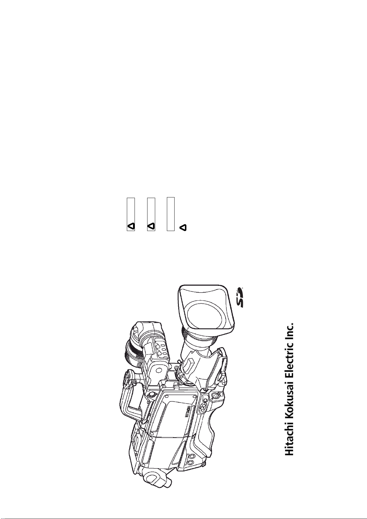
SK-HD1300-S3
SERVICE MANUAL
CONTENTS
1. SPECIFICATIONS
2. OPERATING INSTRUCTIONS
3. DISASSEMBLY
4. ADJUSTMENT
5. BLOCK DIAGRAMS
6. SCHEMATIC DIAGRAM
7. ELECTRICAL PARTS LIST
8. PARTS ARRANGEMENT
9. MECHANICAL PARTS LIST AND EXPLODED VIEW

1.
SPECIFICATIONS

Camera Head SK-HD1300-S3
2/3-inch, MOS image sensor
1 Image sensor
2 Native Scan 1080/59.94p 1080/50p
3 Prism F1.4
4 Optical Filter
5 ECC Filter 3200 K, 4300 K, 5600 K, 7500 K, FAW (Full-time Auto White)
6 Lens mount B4 Bayonet
7 HD Resolution 1100TVL
8 HD SNR
9 Sensitivity
10 Minimum illumination 2 lx (at F1.4, GAIN: +24 dB)
11 Modulation Depth 50% (16:9, Center of picture @27.5MHz)
12 Vertical Smear No smear
13 Gain selection
14 Shutter 1/250, 1/500, 1/1000, 1/2000 second
15 Lock scan
16 Geometric distortion
17 Registration Overall 0.01 % (excluding lens characteristics)
18 Dimensions 133(W) x 191(H) x 262(D) mm
19 Power supply voltage DC 12 V (10.5 V to 17 V )
20 Operating temperature -10 °C to +45 °C , 14 °F to +113 °F
21 Storage temperature -20 °C to +60 °C , -4 °F to +140 °F
22 Power Consumption 28W Head only (without VF)
23 MASS approx. 2.1kg, 4.6lbs, Head only (without VF)
24 Input & Output
Total pixels 2,270 (H) × 1,144(V) 2.6 million pixels
Effective pixels 1,920 (H) × 1,080 (V)
1X motorized filter wheel w/ 4 filter positions
(Clear, Cross, 1/16 ND, 1/64 ND)
Typical 59dB: 1080i 50/59.94Hz
56dB: 1080i 150/179.82Hz
(HD-SDI output decode Y channel)
1080/59.94i :F10 @ 2000 lx, 3200 K, 89.9% reflectance
1080/50i :F11 @ 2000 lx, 3200 K, 89.9% reflectance
1080/179.82i :F7.3 @ 2000 lx, 3200 K, 89.9% reflectance
1080/150i :F8 @ 2000 lx, 3200 K, 89.9% reflectance
L (low) -3/0dB
M (medium) 0/+3/+6/+9/+12/+15/+18/+21/dB
H (high) +3/+6/+9/+12/+15/+18/+21/+24 dB
1/180.7 to 1/2043 second (59.94i scan)
1/150.8 to 1/1939 second (50i scan)
Negligible (excluding lens characteristics)
MON/RET OUT: BNC x 1, HD-SDI
Monitor output (1080i or 720p switchable),
VF out (Character ON/OFF )
RET out
REMOTE: 4-pin Multi connector for remote control panel
VF: 20-pin Multi VF connector
LENS: 12-pin Multi LENS connector
MIC: 3-pin XLR MIC-1 connector
SD Memory Card Slot

2. OPERATING INSTRUCTIONS
B
SAFE TY ALERT SYMBOL
NOTE: Notes indicate an area or subject of spec ial merit, em phasizing either the
WARNI NG: Personal danger
Warning notes i ndic ate any condition or practice, which if not strictly observ ed, could
result in personal injury or possible death.
CAUTION: Possible damage to equipment
Caution notes indicate any c ondition or practice, which if not strictly observed or
This is the “Safety Alert Sy mbol.”
This symbol is used to call yo ur attention to item s or operat ions that could be dangerou s to you
or other persons using this equipm ent. Read these messages and follow these instructions
carefully.
product s capabilities or comm on errors in ope ration or m aintenance.
remedied, could result in damage or destruction of the equipment.
COLOR CAMER A T O RAIN OR MOISTU RE.
SAFETY INSTRUCTIONS
WARNING
Carefully read all safety m essages in this m anu al and safety Instruc tions on your equipm ent.
Follow recom mended precautions and safe operati ng practices.
SK-HD1300-S3
HD COLOR CAMERA
OPERATING INSTRUCTIONS
It is essential that you read th e instructions and saf ety regulations before you a ttempt to assem ble or use
this equipment.
!
The definitions of signal words are as follows:
CAUT ION
!
NOT E
!
WARNI NG: T O REDUCE THE RISK OF FIRE OR ELE CTRIC SHOCK, DO N OT EXPOSE THIS
Afin d’év iter tout risque d’incendie ou d’électrocution, ne pas exposer l’appareil á la pluie ou á l’hum idité.
Afin d’éc arter tout risque d’él ectrocution, garder le coff ret fermé.
Ne confier l’entretie n de l’appareil qu á un p ersonnel qualifié.
Um Feuergefahr und die Ge fahr eines eiektrischen Schiages zu vermeiden , darf das Gerät weder Regen
noch Feuchtigkeit ausgesetzt werden.
Um einen elektrischen Schiag zu verm eiden, darf das Gehäuse richt geöffnet werden.
AVERTISSEMEN T
VORSICHT
Überiassen Sie W artungsarbeiten stets nur einem Fachm ann.
A
Please read these operating instructions carefully for proper operation
and keep them for future reference.

D
a. When th e power-supp ly cord or plu g is damag ed.
b. if liqu id h as been spilled, or objects hav e fallen into the product.
c. If the produ ct has been ex posed to rain o r w ater.
For adde d protection for this product du ring a ligh tning storm, or whe n it is left unattended and
unused for long periods of tim e, unp lug it from the w all o utlet. This will prevent d amage to the
product due to lightning and power-line surges .
Do n ot o verload wall outlets, extensio n cord s or integral convenience receptacles as th is can result in
a risk of fire or electric shock.
Neve r push objects of any kind into this pro duct throug h openings as the y may touch dang erous
voltage poin ts or sh ort -out parts that could result in a fire or electric sh ock. Never spill liquid of
any kind on the pr odu ct.
Avoid using this product w here there are gase s, and also where there are inflammable an d explosive
substances in th e im med iate vicinity.
When carrying this product aro und, do not subject the product to heav y shock or vibration.
Do n ot attempt to service this p r oduct you rse lf as ope ning o r removing cove rs may exp ose you to
dang erous voltage or other hazards. Refer all servicing to qualified se rvice personnel.
Unplug this produc t from the wall outlet and refer servicing to qualified s ervice personnel un der the
14. L ightning
15. O verloading
16. O bject and Liquid Entry
17. Inflammable and Explosive Substan ce
18. Heavy Sh ock or Vib rati on
19. Servicing
follow ing co nditions:
20. Damage Requiring Service
d. If the product do es not operate n orm ally by following the ope rating instructions. Adju st only
e. If the p rod uct has been dropped or damaged in any w ay.
those controls that are covered by th e operating instru ctions as an im pro per adju stm ent of other
f. Whe n the product exhibits a distinct chang e in performance -this indicates a need for service .
controls may result in damage and will often require extensive work by a qualified technician to
restore the product to its n ormal operation.
When replacem ent par ts are req uired, be sure th e se rvice tech nician has used replacem ent par ts
specified by the manufactu rer or have the same ch aracteristics as the origin al part.
Unautho rize d substitutions may result in fire, electric shock, or other hazards.
Upon completion o f an y service or repairs to th is p rod uct, ask the service technician to p erform
safety checks to determ ine that the product is in proper operating condition.
The product sh ould be mounted to a wall or ceiling only as r ecommended by the man ufacturer.
The product sh ould be situ ated away from heat sources such as radiators, heat registers , stoves, or
21. Replacement Parts
22. Safety Check
23. W all or Ceiling Mo un tin g
other produ cts (including amplifiers) that produce heat.
24. Heat
IMPORTANT SAFETY INSTRUCTIONS
C
All the safety and operating instructions should be read before the product is operated.
The safety and operating instructions should be retaine d for future reference.
All warn ings on the product and the operating instructions should be ad hered to.
All operating and u se instructions sho uld be followed.
Unplug this produc t from the wall outlet before cleanin g. Do not use liquid cleaners or aerosol
clean ers. Use a damp cloth for cleaning.
Do n ot u se attachments not recommende d by the product manufactu rer as they may cause hazards.
Do n ot u se this product near water - for example, near a bath tu b, wash bowl, kitchen sink, or
laundry tub; in a wet basement; o r n ear a swimmin g po ol; and th e like.
Do n ot p lace this product on an u nstable cart, stand , tripod, bracket, or table. The product may fall,
causing serious injury to a child or adult, and serious dam age to the product. Use o nly with a cart,
stand, tripod , br acket, or table recommended by the manu facturer, or sold with the produ ct. Any
moun ting of the produ ct should follow the manufacturer's in stru ctions, and should use a mounting
accessory recom mended by th e manufacturer.
A product and cart combin ation sho uld be moved with care.
Quick stops, excessive force, and un eve n surfaces may cause th e product and cart co mbination to
overturn.
Slots and ope nings in the cabinet are pro vided for v entilation and to e nsure reliable operation o f the
product and to protect it from overheatin g, and these openings must not be blocked or cov ere d.
The openings should n ever be blocked by placing the product on a bed, sofa, rug, or oth er similar
surface. This product should not be placed in a built -in installation such as a bookcase or rack
unless prope r v entilation is provided or the manufacturer's in stru ctions hav e been adhered to.
This product should be operated only from the type of power source indicated o n the marking label.
If company. For products intended to operate from battery power , or other sources, refe r to the
operating instru ctions.
This product is equ ipped with a three-wire grounding-type plug a p lug having a third (grounding )
pin. This plug will only fit into a g rou nding -type power ou tlet. This is a safety fe ature. If you are
unable to insert the plug into the outlet, contact your electrician to replace you r o bsolete outlet. Do
not d efeat th e safety pu rpo se of th e grounding -type plug.
Power-supply cord s sh ould be routed to that they are not likely to be walked on or pinched by items
placed upon or against them, paying particular attention to cords at plug, co nvenience re ceptacles,
1. Read Instruction s
2. Retain Instructio ns
3. Heed Warnings
4. Follo w Instructions
5. Cleaning
6. Attachmen ts
7. Water and Moisture
8. Accessories
9. Moving
10. Ventilation
11. Pow er Sou rces
12. G rou nd ing or Polari zati on
and the poin t where they exit from th e product.
13. Pow er-C ord Protection

F
a. Wenn das Netzkabel ode r de r Steck er besc häd igt ist.
b. Bei Eindringen von Flüssigkeit oder Fre mdkörp ern in das Gerät.
c. Wenn das Erzeu gnis Regen oder Wasser ausgesetzt worden ist.
Für zusätzlichen Schutz des E rzeugnisses während eines G ewitte rs oder bei Nichtv erw endung für
lange Zeit d en Stecker aus der Steckdose zie hen. Dies verhütet Beschädigung durch Blitzsch lag
und Netzspannungsstöße.
Wand steckdosen , Verlängerungskabel und eingebaute Bequem lick keitssteckdo sen nicht überlasten,
da dies F euer oder elektrischen Schlag verursachen k ann.
Niemals Objekte irgendw elcher Art du rch die Öffnungen in das Gerät schieben, da diese unte r
hoher Spannung stehende Teile berühren ode r kurzschließen kön nen , w odurch es zu Feuer ode r
elektrischem Schlag ko mmen kann. Niem als Flüssigkeiten irge ndw elcher Art au f das Erzeugn is
verschü tten .
Vermeiden Sie Verw endun g dieses Erzeugnisses an Orten mit Gasen bzw . entflammbaren o der
explo sive n Substanzen in d er direkten Umgebung.
Setzen Sie das Erzeu gnis be im Transport nicht starken Stößen o der Vibrationen aus.
Versuch en Sie nicht, diese s Erzeugnis Selbst zu warten , da Sie sich durc h Öffnen bzw . Entfe rnen
von Abdeckungen hohen Spannungen und sonstigen G efährdungen ausserzen kön nen.
Beziehen Sie sich für jeg liche Wartung auf qu alifiziertes Wartun gspersonal.
Ziehen Sie den Stecker dieses Erzeugnisses aus der Steckdose und wende n Sie sich an qualifizierte s
14. Blitzschlag
15. Überlastung
16. Eind ringen von Frem dkö rpern und Fl üssigkeit
17. Entflammbare u nd exp losive Substanzen
18. Starke stöße oder Vibrationen
19. W artu ng
Wartung spersonal, wenn eine der folgende n Bedingu ngen vorliegt:
20. Beschädigung, di e Wartu ng erfo rdert
d. Wenn das Erzeugnis bei Befolgen der Bedienu ng san leitu ngen n icht normal funktioniert.
Nur die Reg elelemente verstellen, die in den Bedienungsanleitungen beh andelt werden, d a
e. Wenn das Erzeugnis falle n gelassen ode r beschädig t w ord en ist.
unan gemessene Einstellung anderer Regeleleme nte Beschädigung verursachen kann un d oft
f. Wen n das E rzeugnis eine klare Änderu ng in der Leistun g zeigt -dies weist darauf hin, daß
beträchtliche Arbeit durch einen qualifizierten Technike r erfordert, u m d as Erzeugn is w ied er, zu
normalem Betrieb zu rückzubringen.
Wartung erforderlich ist .
Wenn Ersatzteile erforderlich sind, darauf achten, daß der Wartu ngs techniker nur die vom
Hersteller festgelegten Ersatzteile o der Teile mit den gleichen C harakteristiken wie die
ursprün glichen Teile verwendet. U nautor isierte Ersatzteile können Feuer, elektrischen Schlag
oder son stige G efährdungen verursach en.
Bitten Sie den Wartungstechn iker nach der Vo llendun g von Wartung oder Reparaturarbeiten an
diesem Erzeu gn is um die Durchführ ung v on Sicherheitsprü funge n, um zu bestimmen , daß das
Erzeu gn is im angemissenen Betriebszustan d ist.
Das E rzeugnis sollte nur entsprechen d den Empfehlun gen des H erstellers an einer Wand ode r an
der Decke angebracht werden.
Das E rzeugnis sollte fe rn von Wärm equ ellen wie Radiatoren, Heizwiderständen, Öfen und an deren
21. Ersatzteile
22. Sicherheitsp rüfung
23. Anbri ngung an der Wand od er an d er Decke
Wärme erzeugenden E rzeugnissen (einschließlich Verstärkern) aufgestellt w erden.
24. W ärme
WICHTIGE SICHERHEITSANWEISUNGEN
E
Vor Betrieb des Erzeugnisses sollten alle Siche rheits -und Bedienungsanleitungen gelesen w erden.
Die Sich erh eits -und B edienu ng sanleitungen s ollten fünftigen Bezug aufbewah rt werden.
Die Warnunge n auf dem Erzeug nis un d in den Bedienungsanleitunge n solten beach tet w er den.
Alle Bedienungsanleitung-und
Verwendun gsanweisungen sollten befolg t werden.
Den Stecker de s Geräts vor Rein igung aus der Ste ckdose zieh en. Ke ine flü ssigen Rein igungsmittel
oder Aerosolreiniger v erw enden . Zum Reinigen einen feuchten Lappe n verwenden .
Nur vom -Hersteller des Erze ugnisses empfohle nes Zu behör verwenden, da es sonst zu Störu ng en
kommen kann.
Dieses Erzeu gn is nicht in der Nähe von Wasser verwenden - z.B, in der Nähe einer Badew ann e,
eines Waschbeckens, einer Küch enspüle, eines Waschzubers, in einem nassen Keller, in der Näh e
eines Sch wimmbeckens usw.
Das E rzeugnis nicht auf e inen u n stabilen Wagen, Stand, Dreifuß, Träger oder Tisc h stellen.
Das E rzeugnis kann sonst herunterfallen u nd ein kind oder einen Erw achsen en schwer ve rietzen.
Außerdem kann das Gerät sch wer be sch ädigt w erd en. Nur m it einem Wagen, Stand, Dreifuß,
Träg er oder Tisch verwend en, der vom Hersteller e mpfohlen oder mit dem Erzeu gn is v erkauft
worden ist. Für jegliche Anbringung sollten die Anweisungen des H erstellers befolgt werden, und
das vom Hersteller empfohlene Anbringungszubehör so llte verwendet werde n.
Schneller Halt, übermäßige Krafteinwirkung u nd un ebene Oberflächen k önnen Umkippen der
kombination von Erzeugnis und Wagen verursach en.
Schlitze und Öffnungen im G ehäuse dienen der Ventilation. Sie sind für zuverlässigen Betrieb des
Gerätes und Schutz vor Überhitzung erforderlich und dürfen nicht blockiert oder abgedeckt werden.
Die Öffnungen sollten niemals dadurch blockie rt w erden, daß, das G erät auf ein B ett, ein Sofa,
einen Teppich oder eine ähnliche Oberfläche geste llt wird.
Das G er ät sollte nur dann in Einbauinstallierung w ie in einem Bü cherschr ank ode r e inem G estell
verw endet werden , w enn angemessene Ventilation vorgesehen ist bzw. Die Anwe isun gen des
Herstellers befolgt wor den sind.
Dieses Erzeu gn is sollte nur an de r auf dem Typenschild angegebenen Strom versorgungsart
betrieben werden. Wenn Sie nicht siche r sind, was fü r eine Stromv ersorgu ng Sie haben, so we nden
Sie sich bitte an Ihren Erzeug nishändler oder an das lokale Elektrizitätswerk. Beziehe n Sie sich
für B atteriebetrieb o der andere Stromquellen vorgesehene Erzeugnisse bitte auf die
Bedie nungsanleitungen.
Dieses Erzeu gn is ist mit ein em Schutzkon taktstecker mit d rei Leitern ausgerüstet, mit einem
Erdu ngskontakt. Dieser Stecker paßt nur in ein schu ko -Steck dose. Dies ist eine
Siche rheitsmaßnahm e. Wenn Sie den Stecker nicht in die Steckdo se stecken können, so w enden
Sie sich bitte an ihren Elektriker, dam it er die ve raltete Schuts des Schutzkontaktsteckers
unwirksam.
Netzkabel sollten so verlegt we rden, deß möglich st n ich t darauf getre ten wird und daß sie nicht
eingekle mmt we rde n, mit besonderer Beachtung der k abel an Stackern, Verlängerungskabe ln und
1. Alle Anweisungen lesen.
2. Die An weisun gen au fbewahren.
3. Warnungen beachten.
4. Anwei sun gen befolgen.
5. Reinigun g
6. Zubehör
7. Wasser un d Feuchtigkeit
8. Aufstellung
9. Ei ne Kombination von Erzeugn is und Wagen so llte vorsichtig bewegt werden.
10. Ventilation
11. Stromversorg un g
12. Erdu ng oder P olarisierun g
dem Austritt des Kabels aus dem Erzeugnis.
13. Netzkabelschutz

H
a. Lorsque le cordon d ’alimentatio n ou sa fiche sont endommagés
b. Si du liquide s’est renv ersé su r l’appareil ou que des objets sont tom bés dedans
c. Si l’ap pareil a été exposé á la pluie ou á l’eau.
Pour renforcer la protection de l’appare il pendant un orage, ou si l’ on s’en éloigne ou qu’on reste
longtemp s sans l’utiliser, le débrancher de la source d’alime ntation. Ceci permettra d’éviter tout
dommage de l’appareil dú á la foudre et aux surtensions de ligne.
Ne pas su rcharger les prises, rallonges et prises multiple s car cela pourrait entraîner un risque de
feu ou d e choc électrique.
Ne jamais enfoncer d’ objets d’aucune sorte dans les ouvertures de l’appareil car ils pourraient
toucher des points de tension dan gereuse ou co urt -circuiter des piéces, ce qui pourrait provoquer u n
feu ou u n cho c électrique. Ne jamais renve rser de liquide d’aucune sorte su r l’appareil.
Eviter d’utiliser l’appareil en prése nce de gaz, ainsi qu’á pr oximité immédiate de substances
inflammables et explosives.
Lorsqu’o n transporte l’appareil, ne pas le soum ettre á des chocs ou des vibrations violents.
Ne pas te nter de réparer l’aapareil soi-mêm e car le fait d’ouvrir ou de retirer les caches risque
d’exposer l’utilisateu r á des ten sion s dangereuses notamment. Confier toute réparation á un
personn el qualifié.
Débrancher l’appar eil de la so urce d’alimentation et confier les réparation s á un person nel qualifié
14. F oudre
15. Surcharg e
16. Pénétration d’objets et d e liquides
17. Substan ces inflammab es et explo sives
18. Chocs o u vibrations violents
19. Réparations
dans les cas suivants:
20. Dommag es nécessitant réparations
d. Si l’appareil ne fonctionne pas n ormalemen t lorsqu ’on observe les instructio ns d’utilisation.
e. Si l’appareil est tombé ou qu’il a été endommagé.
Ne régler que les c omm andes couver tes par le mode d’emploi ; en effet, un réglage incorrect des
f. Si l’appareil affiche un e nette modification de ses performances, ce la signifie qu’il a besoin
autre s commandes p ourrait entrainer des dommages et n écessite ron t so uvent des travaux de
réparatio n coûteux par un technicien qualifié pour remettre l’appareil en état de m arche.
d’être ré paré.
Si l’on a besoin de p iéces de rechange, veiller á ce que le tech nicien de rép arati on utilise
exclusiveme nt les piéce s de re change spécifiées par le fabricant ou des piéces ayant les mêmes
caractéristiques que les piéces d’origine. Les piéc es de rech ang e non autorisées risquent de
provoquer un feu, un ch oc électrique et autres d angers.
Aprés tout travail d’entretien o u de réparation de l’appareil, demander au technicien de réparation
d’effectuer les vérifications de sécurité pour s’assurer que l’appar eil est en bon état de m arche.
L’app areil ne pourr a être monté au mur ou au plafond que de la man iére recommandée par le
Eloigner l’appareil des sources de chaleur, telles que radiateurs, appareils de chauffage, cu isiniéres,
21. Piéces d e rechange
22. Vérificaton de sécurité
23.Montage au mur ou au plafo nd
et de tou r produit e ngendran t de la chaleur (y co mpr is les amplificateurs).
fabricant.
24. Chaleur
MISES EN GARDE IMPORTANTES
G
Lire toutes les instructions de sécurité et de fonctionn ement avant de faire fonction ne r l’appareil.
Conserver les instructions de sécurité et de fonctionnement á des fins de référence ultérieure.
Tous les avertissements qui figur ent sur l’appareil et d ans le mode d’emploi devront être respectés.
Observer to utes les instructions de fonctionn ement et d ’utilisation.
Avan t de procéder au nettoyage, débran cher l’ appareil de la prise secteu r. Ne pas utiliser de
produits de nettoyage liquides ou en aérosol.
Nettoyer l’appareil avec un chiffon h umide.
Ne pas utiliser de fix ations non recomman dées par le fabricant de l’appareil car elles p ourraient être
source de dang er.
Ne pas utiliser l’appareil á proximité d’eau -par exemp le prés d’u ne baig noire, d’u n lavabo, d’un évier
ou d’un bac á lessiv e, dans un sous-sol humide, ou prés d’une piscine , etc.
Ne pas placer l’appareil sur un chariot, un socle, u n pied, un support ou one table in stables
L’app areil pourrait tomber, blessant griév ement des enfants ou des adu ltes, et étant sérieusement
endommagé.
Utiliser exclusiveme nt le chariot, le so cle, le pied, le support ou la table recomman dés par le
fabrican t, ou vendus avec l’appareil. Pour tout mo ntage de l’appareil, respecter les instruction s du
fabricant, et utiliser á cette fin l’accessoire de montage recommandé par le fabricant.
Des arrêts brusques, u ne force exce ssiv e et des surfaces irréguliéres pourraien t provoquer le
renv erseme nt de l’ensemble appareil -chariot.
Les fente s et les ouvertures du coffret sont prévues pour la ventilation ainsi que pour garantir un
fonction nement en toute sécu rité de l’appareil et le protéger de toute surchauffe, e t ce s ou vertures ne
devront donc être ni obstruées ni recouvertes. Ne jamais o bstruer les ouvertures en placant
l’appareil sur un lit, un so fa, un tapis ou toute surface sim ilaire. Ne jamais placer l’ appareil dans
un support confiné, par e xemple une bibliothéque ou une é tagé re, sans v entilation suffisante ou
sans repecter les instructions du fabricant.
L’app areil devra être alime nté exclusivem ent sur le type d’alimentation indiqué sur l’étiqu ette
signalétique. Sil’on n’est pas sû r du type d’alimentatio du local, consulter le revendeur de l’appare il
ou la compagnie d’électricité locale. Pour les appareils qui fonction nent sur batte rie ou sur
d’autres source s, v oir le mode d’emploi.
L’app areil est doté d’un e fiche trifilaire avec mise á la terre , dont la troisié me broche assure la m ise á
la terre. Cette fiche ne rentrera que dan s le s prises trifilaires d e m ise á la terre. Ceci est une
mesure de sécu rité. Si la fiche ne rentre pas dans la prise, faire remplace r la prise désu éte par un
électr icie n.
Ne pas rendre vaine la me asure de sé curité assu rée par cette prise avec mise á la ter re.
Ache min er les cordons d’alime ntation de faco n qu’on ne risque pas de march er dessus ou d e le s
coincer sous un objet p lacé dessus ou con tre eux.
Faire particuliérement attention au x fich es des cord ons, á la proximité des prises, et á l’e ndroit oú ils
1. Lire les instructions
2. Conserver ces instructions
3. T enir comp te des avertissemen ts
4. Observer les instructions
5. Nettoyage
6. Fixati ons
7. Eau et h umidité
8. Accessoires
9. L’appareil monté su r son chariot devra être déplacé avec précaution.
10. Ventilation
11. Sources d’allmentation
12. M ise á la terre o u polarisation
13. Protection du cordon d ’alimentation
ressorten t de l’appareil.

Contents
Wa rnings and cau tions wh en us ing ............. ................... ............ .................... .. .... ..... .... .... .... .... .... ...... ........ 4
Fac ility name s and func tion s A ................ ................ ................. .................................... .... ....... .. .... ..... .... .... . 6
Lens ins tal lation ..... .... .... .... .... .... ....... ... .... ............................ .... .... .... .............................. .... .... .... .... ... ......... 14
Lens flange bac k a djus tment ....... ........................... ............................. .......................... .... ... ..................... 15
Wh ite sha ding adju stm ent ....................... ........... .... ............. .... .... .... . ........ .... .................... .................... ..... 16
Cam era number ins tallation ( opti on) ....... .... .... .... ............. ........ .... ..... .... .... .... ... ........... ....................... ........ 18
Tri pod m ountin g........................... ....... .... .... .... .... .............. ................................ ........................ ........ ...... ... 19
View finder adjus tment ... .... .... ............. .... .... ........ .... ..... .... .... .... ... ................ ................ ................. .............. 20
View finder indicati ons ......................... .... ... ............ .................... .. .... ..... .... .... .... .... .... .. ............................... 22
Filt er sel ection ...... ..... .... .... .... .... .... ............... .... ............................... ............... ........... .... ........................... . 23
Wh ite and b lac k b ala nce adjustm ent ... ................................ .... .... .... .............................. .... .... .... .... ... ......... 24
Elec tro nic shutte r setting ......... ....................... .... .... ........................ ...... ......................... .. .......................... 29
Setup card ........................ ........ ...... .... .... .... .... .... ..... .......................... ....... .................... ............ .............. ... 31
Func tion menu .. .... ..... .... .... .... .... .... ....................... ............................... .... ....... ........... .... .... ........................ 38
Spec ifi cations ... .... ..... .... .... .... .... .... ......... .... .... .... .... ..... ............................... ... ... .... ................. .... .... ............ 74
Studio s ys tem operation .... .... .... ..... .... .... .... ... ........... ....................... .............................. .... .... .... .... .... ..... ... 79
Stand-A lone system operati on ... .... ......................... ......... .... .... .... .... ....... .. .... ................. .... .... ... ................. 80
Appli cation not e: C onn ecting pro mpt er p ow er .... .... ........................ ...... .... ..................... .. .... ...................... 83
I
IMPORTANT NOTICE
Chan ges or modifications n ot expressly approved by Hitachi Ko kusai Electric responsible for
These produ cts have been tested and found to comp ly with the limits for a Class A digital dev ice,
pursuan t to Par t 15 of the FCC Rules. These limits are d esigned to provide reason able pr otection
again st h armful interference wh en the equ ipment is operated in a commercial environ men t. This
equipment g ene rate s, u ses, and can radiate radio frequency energy and , if not installed an d used in
accordan ce with the instruction manual, may cause ha rmful inte rference to radio commu nications.
Operation of this produ ct in a residential are a is likely to cause harmful interference in which case
For USA
the u ser will be required to correct the inte rference at his ow n expense.
complian ce cou ld void the user’s authority to operate the equipme nt.
WARNING
This product does not exceed the class A/class B limits for radio noise emissions fro m digital
apparatus as set out in the radio interfere nce re gulation s.
Le présent appareil n’é met pas de bruits radioélectriques dépassant les limités applicable aux
appareils nu mériques de classe A prescrite s dans le rVgle men t sur le brouillage radioé lectrique
For Canada
édicter p ar le min istére des communications du can ada.
NOTICE
These spec ifications are subject to change without prior notice due to product improv ement.
Confirm the m ost recent specifications at tim e of order.
Hitac hi Kokusai E lec tric certif ies this prod uct com plies w ith the standard warranty conditions of Hitachi
Kokusai Electric, and that quality control is im plemented to the extent required to com ply with those
conditions.
intentional act are excluded.
perform ed at charge.
failures as well as ex penses incurred b y disassembly and reassem bly of the related system, are bey ond
the scope of this W arranty.
are beyond the scope of this Warranty.
use f or business trades, pro duction process, medical fields, crime prevention applications, etc.
When the stable operation is required f or a long time, it is recom mended to perform per iodical
maintenance and inspect ion every year or every two years.
under the environments of high temperature or high humidity.
Warranty and service
(1) The guarantee period is one year after the data purchase. Howev er, the defects due to erroneous use or
(2) A s the def ect aft er expirations of the guarantee period, where product repair is possible, r epair will be
(3) The present W arranty pertains only to the cam era unit . Secondary ma lfunct ions attribut able to cam era
(4) Compensation for loss of business, loss or damage to software, d atabase and other contingent losses
(5) Hitachi Kokusai Electric Inc. is not liable for the losses caused when the equipm ent is used in a system,
(6) T he parts used in the equipment hav e their respective liv es. The lives of such parts will be shortened
(7) In the case of camera trouble by m iss wiring of cable, it will be considered as out of warranty.

The SK -HD1300-S3 is Hitach i’s new
HDR (H igh Dy namic R ange):
2
scene highlights above 100%.
HDR reproduces the high contrast pictu re
which a conventional TV came ra could not
provide in a highlight scene by combin atio n
with a HDR m onitor.
Blac k Gam ma function can co ntrol Initial
Gam ma g ain mo re fine ly th an conve ntional
Blac k Stretch. Ind ependent Initial Gamm a
controls are provided for the Red , Green and
Blu e channels providing a fine granularity
control o ve r d ark color.
The 12- vector and linear m atrix pro vid e th e
user a wid e latitude in su bject image color
control. The 6 -axis linear matrix prov ide s
ove rall color control and the 12 -vector colo r
corrector provide s independent contro l of the
hue and saturation for each of the three
primar y and the thre e secondary co lo rs.
Color matrix can be changed to several
broadcast cam era standard s.
Skin to ne maskin g provides “fin e” “Paintin g”
(hue and saturatio n) o f Skin tones witho ut
affecting other colors in the scene.
Auto Ch roma autom atically reduces
ove r-standard colors in the im age caused by
extreme ly bright and colorfu l objects such as
em ergency vehicle lights or stage lighting
L.E.D’s.
Ne w Skin tone Detail functions allow a
flesh-co lor based soft ening o f the im age to
achieve a much more youthfu l look for
on-camera pe rsonalities.
Three indiv idual channels exist as we ll as a
function to automatically de tect the hue,
saturation and luminance of the Skin tone to be
affected.
Furthe rm ore, the Skin tone Detail level can be
adjuste d to follow the lens' zoom to avoid
'rubber face s' in wide angle shots while using
the fu nction.
This “through the lens” autom atic setup is uses
a stand ard gray scale chart to automatically
setup gain, gamma, black an d flare thus saving
the vid eo operator time and e ffort.
Autom atic w hite shading corrects white
vertical and horizontal shadin g at the push of a
button. This function provid es separate
me mory of le ns’ modulation sha ding
characteristics to optim ize the X1 and X2 len s
Black G amma:
Outline and features
Multi-standard High -Speed (Slow Motion)
camera.
With its new 2.6 million pixels 3 -MOS, the
SK-HD1300-S3 prov ides thre e times high spe ed
superior picture, an d is suitable for shooting live
sports productio ns.
Shutter problems(jitter, ske wing effect, flick er
12-V ector and Linear M atrix masking :
Three times scanning speed HD output: 1080i
150/179.82Hz or 720p 150/179.82Hz from CCU
with wideband and long distance optical fiber
and etc.) are not clearly recogn i zable in standard
production use.
Outstanding Features
Hig h s pee d m otion out put
transmission.
Preset M asking :
Skin tone masking:
1080i 50/59.94Hz and/or 720p 50/59.94Hz
Both three times speed picture and normal speed
picture output simultaneously from CCU.
・1080i 150/179.82Hz or 720p 150/179.82Hz
・
The brand new, powe r efficie nt Digital Signal
Mult i frame rate
Latest gen eration D igital t ech no log y
Auto Chro ma:
Processor LSI pro vid es very faithfu l video
image repro duction and qu ality.
Digital video pro cessing and encoding provide
low interferenc e and high stability.
Low noise circuit technology provides a low signal
High sensitivit y and Signal to N oise rat io
New 3ch skin tone detail:
to noise ratio: 59dB (1X output), 56dB (3X output)
and the standard sensitivity F11 at 2000lx
(1080i/50 or 720p/50), F10 at 2000lx (1080i/59.94
or 720p/59.94)
Even at high gain, clear images are obtained with
low noise
The ne w streamlined camera body design has a
low center o f gravity for ease of use o n th e
shoulder. The ligh tweig ht cam era body is
designed with strong die - cast aluminum
sections that are resistant to m ino r im pacts
and provide s soundp ro ofing for motorized filter
The new streamlined body design
turrets and cooling fans. So there is n o
Gray Scale Autom atic Se tup :
adve rse effect to cam era video signals and the
user setup and Scene File information.
enviro nment for stud io.
A small plug-in setup card (SD card) stores the
Setu p card
Auto matic White Shadin g:
Highl ight Q uality
( RL AC ):
Lens chromatic aberration of magni fication is
Real-time Lens Abe rration Co rrection
Digital p roce ssin g im prove s Im age
extende r p osition s.
1
reduced by digital processing with supporting
lenses. Kn ee saturation and auto-knee :
The auto knee prov ides a wide dynamic range
by dynam ically compre ssing the vid eo level
above 100%.
Knee saturatio n restores color saturation to
switches and controls other than design ated.
danger o f touching internal high voltage
com ponents.
Viewfinder h igh voltage
Do not open the view fin der cover. Th ere is
A lens, microphone and other cables, grasp the
conn ector by the body, not the attached cable.
Cables can be damaged by pulling on them.
When transporting by hand, use the carrying
case. If shippin g by truck or other means,
pack in the carry ing case, then use furthe r
cushioning and pack in a sturdy carton .
Use a recommended tripod and install the
camera correctly.
Use a photographers air blower to clear dust
from the lens and filters. Wipe the case with a
soft dry cloth. D o not use volatile solven ts, as
these may deform th e materials.
Disco nnect from pow er and contact the nearest
When conn ecting an d discon nectin g
N ote w hen transporting
Tripod
Cleaning
Hitachi K ok usai Electric service agency.
In event of difficulty
4
other bright light source. There is danger of
phy sical burn s and loss of eyesight.
pointed toward the s un. There is risk o f burn
View fin der lens h azard
Warnings and cautions when using
Do not point the eyelen s toward the sun or
CA-H F1300-S3
The SK-HD1300-S3 can be co nstructed a fiber
cable system.
Camera adaptor:
Studio system configuration s
dam age to the vie wf ind er interior.
Do no t place the vie wfind er with the lens
CU-HD1300- S3
RU-1500JY/R U-1500JY-S3
Camera control unit:
Remote control un it:
The specified power sup ply in put voltag e of this
camera is 12VDC. Be sure to use th e designated
powe r supply.
The camera contains precision internal
compone nts. Do not open the cover or disturb
There is risk of imp aired performan ce and
Power supply
SU-1000
Setup control un it:
2-inch color LCD ENG view finder:
Do not disassemble or modify
VF-L20H D
VF-402
VF-L90H D
2-inch black and white ENG viewfinder:
9-inch color LCD studio view finder :
damage.
Keep foreign object out of int erior
HDF -EL800H
VF-701H DA-H
7.4-inch color OLED stu dio viewfin der:
7-inch color LCD studio view finder:
Studio adaptor:
Avoid using or storing the equipment in the
Entry of water, metallic or other foreign
materials can cause failure and damag e.
Select u se and sto rag e locations caref ully
SA-1000/SA-1000-S3
-10 to 45°C), such as in enc losed vehicles.
follow ing types of location s. Impaired
perfo rmance and damage can be cau sed.
Extremely hot or cold locations (exc eeding
Subject to strong vibration.
or radio transmitters).
Humid or dusty locations.
Salt spray or corrosiv e gases.
Strong electromagnetic field s (e.g., near TV
Where exposed to rain.
heat dissipation duri ng operation.
Do no t cover or otherwise o bstruct camer a
Note MOS image sensor characteristic phenomena
Phen om ena by shoo ting condition
With very brig ht flash light, picture has ver y bright portion and very dark portion in one frame like
partial ex posure. At shootin g fast object, the object image might be to w obble.
Dead pixel
If cosmic rays go through an im age sen sor, a pixel may have damage, and then a dead pixel will
appear on a screen . In high te mperature or h igh gain, it is easier to see dead pixels than in no rmal
The following types of phenome na are innate characteristics of a MOS imag e sensor and are not
malfunction s. Be aware of these w hen u sing a M OS cam era for broadcast or other demandin g
applications.
cond itions.
( The repair is not free of charg e)
Laser light may do damage to imag e sensor. When you use laser light, be carefu l not to irradiate it
on th e imag e sensor surface. The image senso r breakage by laser light is out of w arranty.
Note Dam age by laser
3
Quick Focus autom atically opens the iris then
sets the video level with the electric shutter.
With the resulting shallow depth of focus, the
exact focus p oint c an be set easily.
The user can assign Z ebra, mark er, VFDTL,
Quick Focus, FA W or Digital Extende r to
either of the programmable switches for ease
of o peration.
Gain , de tail, masking, gamm a and other
settings can be stored in eight scene file
memories.
bars are selected .
Outline and features
Extensive User-Friend ly
Qu ick focu s:
User -Programm able Switches (CS-1):
Sc ene Files:
supply .
Audio test tone (1kHz) is output when c olor
Micro ph on e input accep ts phantom p ow er
Color te m perature can be controlled m anu ally .
Menu selection of over -level or between range
zebra is provide d.
View fin der displays
Tw o mo de ze bra :
find er to he lp adjust focus position.
Saf ety zone and center mark display
Fo cus assist ind icator is disp lay ed on a view
16:9.
with em ployed larger VF lens.
High p erform ance v iewfinder ( VF-402 )
Auto fo cus le ns area m arker can be d isplayed.
2-inch black and w hite CRT monitor, aspect
High VF resolution allo ws easy focusing.
to se t best viewing.
Improv ed view ing angle an d distance from eye
Adju stable mech anical VF positio ning and tilt
Built-in top tally
for easy access.
Main operating switches are grouped forward
A conven ient remote controller can be used to
Direct control sw itches
Red tally and green tally are provid ed .
select optical filters.
Rem ote cont rol filter wheel
Viewfinder at tachment
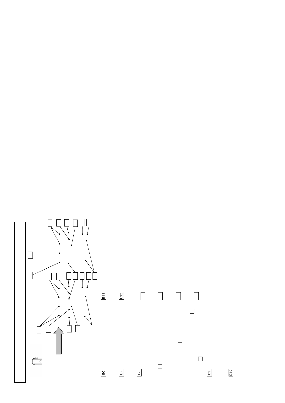
A1
A2
A3
A4A5A6A7A8
A9
Sho uld er belt h ook
CALL button
POWER sw itch
Attachme nt for separately sold shou lder belt.
Press to call the CCU.
Power is su pplied from external unit via DC
Power is supplied from CCU(Camera
Control Unit) via fiber cable. When this
switch is set to “EXT”, camera cannot be
powered on from CCU.
EXT: Pow er supplied via D C input co nnector.
CCU: Pow er supplied via fiber cable.
powe r conn ector F1 (Refer to page 11.)
6
Facility names and functions A
Accessory shoe
A small spotlight can be attached without the
Viewfin der front to rear lock screw
light striking the lens, viewfinder or
microphone .
Lens mount
Setu p card slot(SD card)
Shou lder p ad
Secures th e front to rear position ad justment
of the 2-inch view finder .
B4 Bayonet type lens m ount.
Slot for insertin g setup card. (M AX 2G B)
5
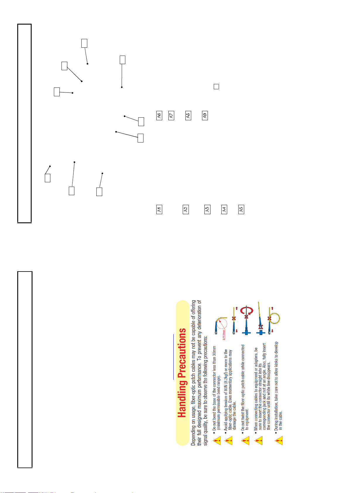
Fiber optical cable assembly man ufacture “CANARE ” has Clean ing kit for the op tical fiber cable
This camera is usin g the optical fiber cable & connector w hich is required specia l techn iqu e for
Optical Fiber Camera Cable & Connector Handling
Warnings and cautions when using
(1) FCF (Fiber Cable Female) (2) FCM (Fiber Cab le Male)
hand ling .
1. Cable Connector & Receptacle
(3) FCFR (F emale Receptacle) (4)FCMR (Male Receptacle)
(1) Cleaning Stick (CANARE CLET OP 2.5/2.0 )
2. Maintenance tool & information
& conne ctor av ailable. Detail is in URL http://ww w.canare.co.jp
(2) CLEANING KIT
).
B1B2B3B4B5
B6B7B8
B9
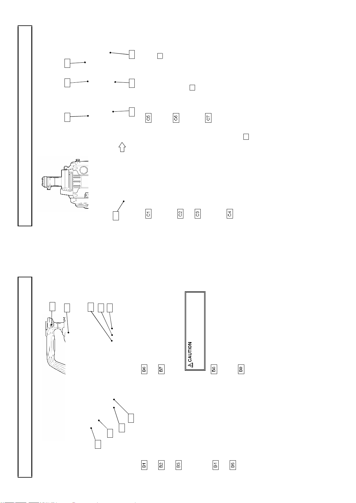
INC OM M IC on /of f bu tt on
C1C5C6
C7C2C3
C4
Inter com microphone can be used while
INC OM LEVE L control
Inter com receiv e level can be adjusted when
pressing this button wh en switch E8 on cam era
adaptor show n pag e 10 is set to “FRO NT”.
switch The intercom level can be ad justed
MENU SE LE CT knob/bu tton
when selected E8 on camera adaptor shown
page 10 is set to “ FRONT”
On screen men u can be operated.
8
Facility names and functions C
AWB(Autom atic Wh ite Balanc e) can
be executed by lifting up the switch.
LEN S connect or (12 pin)
MIC connect or (XL R, 3pin )
Connector for microph one.
The phantom pow er (DC+48V) can be
supplied to front microphone from camera
menu . (Refer to page 63.)
CCU connector
AC230V OUT connector
Connector for fiber optic cable.
Maximum 100VA (AC230V) can be supplie d
to external unit.
For d etail, Refer to page 80.
SHU TT ER switch
Connector for lens cable.
Set to on to use the electron ic shutter. A t the
SEL position, the shu tter speed and mode
are changed in the range set beforehand at
the setting menu.
(1080i) outpu t.
Do not connect the FS-F5 cable
HD -SDI2 connector (BNC )
duri ng the Camera system power on.
CCU system: HD-SDI or Return B video
Please set WHITE BAL switch D 7 to
AUTO W/B BAL swit ch
AW B:
PROMPT/GL connector (BNC )
Only camera: HD -SD I (1080i) outpu t.
CCU system: Prompter signal output .
exec uted by pushing dow n the switch.
A o r B be fore e xecuting AWB.
ABB : A BB(Automatic Black Balance) can be
(Tri-level sy nc or Black burst)
Only camera: Genlock signal in put.
7
Viewfin der connector
Should er belt hook
Attachme nt for separately sold shoulder belt.
MON/RET outpu t con nector (BNC )
Connector for viewfinder cable .
HD-SDI signal outpu t for monitor (75
The same ch aracter signal as the viewfinder
is superimposed on the video signal to allo w
REM OT E connector (4 pin )
RET bu tton
checking the setting menu from the monitor
screen.
Connector for remote control unit.
Video re turn signal of chann el1 on/off button.
While pressing this button, HD -SDI output
from “MON/RET output conn ector ” and the
picture on view finder can be sw itched to
return picture.
Facility names and functions B

D1
D2D4D5D6D7D8D9
D10
0
D3
E4
E5
E1E2E3E3E4
E5
PAL type
E4E5E1
E2
Facility names and functions E
RET1/2 transmissio n sign al switch
This switch is used to select a return video
signal among four external v ideo sources
RET 1/2 switch
input to CCU. These four sign als can be
assign ed by CCU me nu .
Selec ts RET-1/RE T-2 in put.
Selec ted retu rn video is display ed on view
finder w hile this button is pre ssed.
10
NTS C type
CS swit ch
TALLY ON/OFF switch
CS switch can be assigned as a shortcut by
CUSTOM SW menu .
Turn on switch to enable TALLY LED E3 to
RED/GREEN TALLY LED
light, or t urn off switch to prevent from
lighting by mistake.
Ligh ts at green or red tally inpu t.
value for 3200K.
WHI TE BAL switch
PRE: The white balance is set to the memory
A or B: W hen the AUTO W/B BA L switch C4 is
set to AW B, the white balance is adjusted
POWER LED
FILT ER button
Off : Camera pow er is off.
On(Green): Came ra power is o n.
WHITE BAL A and B ar e for E NG operation ,
automatically.
Note
ND button
A fun ction assigned in the CUSTOM SW
menu can be turned ON or OFF.
CS-1/CH ECK swit ch
operating data such as sw itch status,
WHITE BAL A and B become common data
under system operation .
recordin g elapsed time and audio lev el.
CHEC K: View finder display s camera
MENU button
SW menu can be turned ON or OFF.
CS-1: A function assigned in the CU STOM
POWER sw itch
The menu is displayed in VF and MO N/RET
signal.
The pow er switch is not fun ctional.
9
ECC bu tton
GAIN switch
ND filter selects.
ECC filter se lects.
Selects video circuit gain according to scene
OUTPUT/AU TO KN EE switch
Camera mod e with AUTO KNEE o ff.
brightness. Low, m ediu m and high are
BAR: Color bar mo de.
indicated beforehand in th e setting menu.
Camera mod e with AUTO KNEE o n.
CAM /AU TO KNEE OFF:
CAM/AU TO KNEE ON :
Facility names and functions D
Intercom microp hone always works.
E11E1
2
E7E8E6
E7
E9
E1
0
E6E8E9
E1
0
E6
E11E1
2
E8
E13
E14
E15
E16
12
PAL typeNTS C type
volume is ad justed w ith the front
SCRIP T connector
RET CONT connector
Power for script lamp. 12V/maximum 1.0A can be
This co nnector can be use d for controlling
supplied .
ENG intercom level
interco m TAL K ON/OFF. Also RE T1 an d
RET2 can be switche d on/off.
E13
PROD intercom level
Contro ls the receiving sound volum e of EN G
interco m.
E14
TRACKER int ercom lev el
Contro ls the receiving sound volume of PD
interco m.
Contro ls the receiving sound volume of
TRACKER inte rcom.
E15
volume is adjusted with the rear
Intercom volume select sw itch
REAR: Intercom receiving level sound
E16
panel volum e.
panel volum e.
FRO NT: Intercom receiving le vel sound
11
INCOM PG M 1/2 level
Facility names and functions E
INCOM 1/2 intercom level
Controls the receiving sound vo lum e of the
program .
INCOM 1/2 TALK ON/OFF sw itch
Controls the receiving sound vo lum e of the
intercom .
Intercom micro phone can be switch ed on/o ff.
E7.
Intercom receive level is adjusted with
Upper: RE AR MIC m ode
Intercom microphon e is completely
switched off. Intercom receive level is
adjusted with E7 .
Intercom microphone works while C5. is
Middle: OFF m ode
Lower: FR ONT MIC mode
INCOM 1/2 PD/ENG select switch
pressed. Intercom receive level is adjusted
with C6.
This switch is u sed to select the PD or ENG
INTERC OM 1 / INTERCOM 2 con nector
input of the external interco m system to be
conn ected to the CCU rear side.
Intercom headset can be c onnected.
(XLR 5 pin)
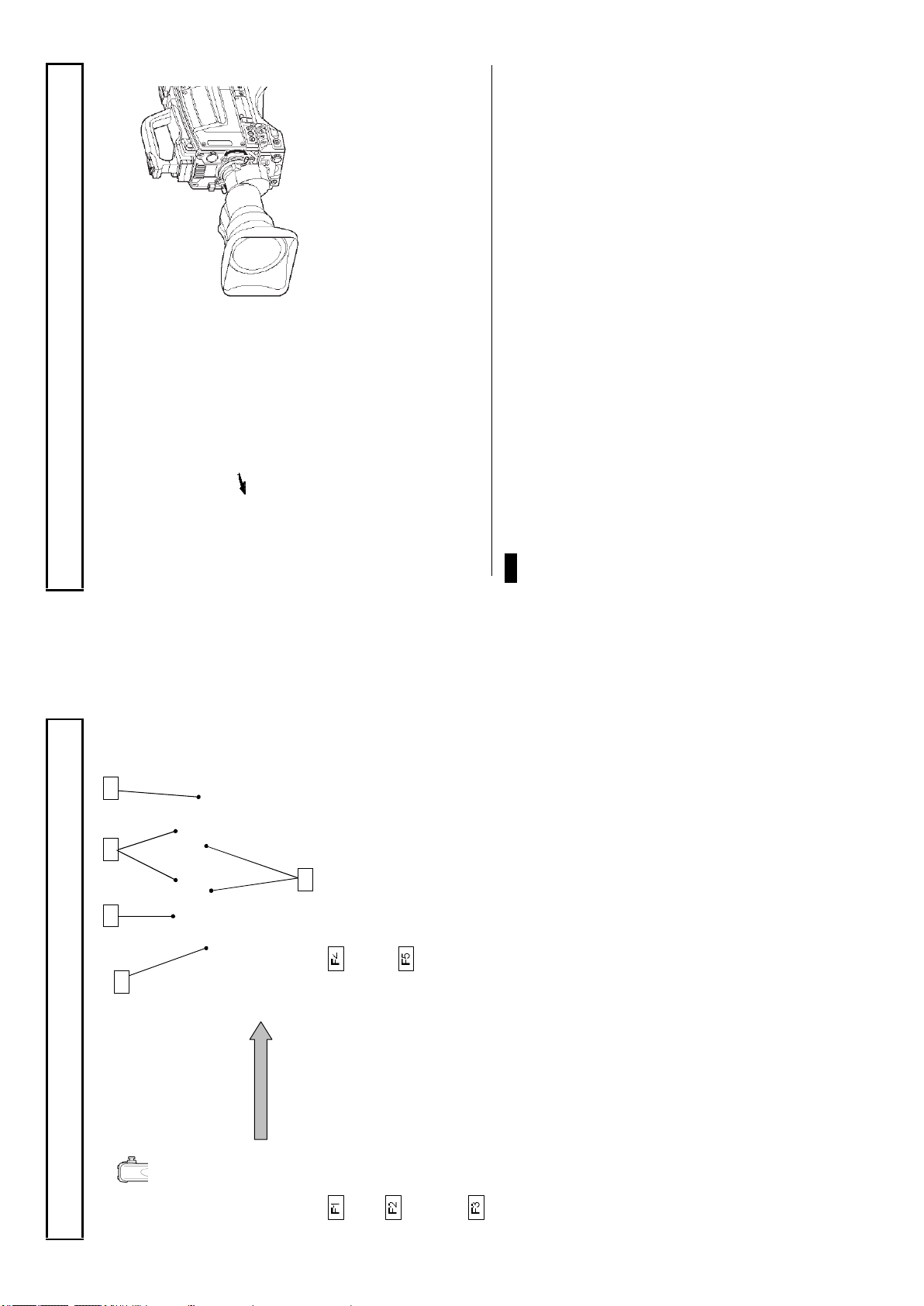
F1
F2
F4
F5
F3
3. Lower the lens lever to se cur e the lens.
conn ect it to the lens connector.
4. Engage the cable with the cable clamp and
14
TALK: INCO M TALK ON /OFF,
the upper part of the lens mo unt and in stall
1. Raise the lens lever and remove the mount
Lens installation
cap.
Lens installation
Install according to the following pro ced ure.
the lens.
2. Align the len s c enter m ark with the indent at
1. Le ns flange back
2. Lens white shading
3. Le ns auto iris speed
The following adjustments m ay be required accordin g to the type of lens.
Note s
4. Le ns iris close limit (AUTO IRIS menu)
Ref er to the lens instructions when using the lens.
RET2: RET2 ON/OFF selected by RET2 SEL in the camera adapter. (Refer to page 9)
1. RET switch: RET1 ON/OFF selected by RET1 SEL in the cam era adapter. (Refer to page 9)
2. VTR switch: Work for TALK or RET -2 function with C USTOM SW MENU setting.
3. EXTENDER: Ex tender LED in VF is lit and “E” is displaye d on V F w hen EXTENDER is on.
MIC LINE/OFF/+48V swi tch
LINE: For a line level signal source .
DC IN connector (XLR 4 p in)
This connector should be used when the
HD -SDI 1 outp ut connector (BNC )
OFF : Not to supply a pow er.
HD-SDI signal output.
+48V: T o su pply a pow er of +48VDC
.
13
MIC SEL swit ch
camera is used in self-con trol mode.
Front microphone or rear m icrophone1.
The front microphon e conn ector or re ar
MIC 1 /MIC2 connector (XLR 3 pi n)
microphone connecto r m icroph one can be
selected.
Connector for microp hone.
Facility names and functions F

GAIN L (0dB)
MENU sw itch
LENS E XTENDER OFF
16
SHUTT ER OF F
MENU SELECT knob/bu tton
White shading adjustment
White shading adjustment
White shading adju stment is recommende d after rep lacing the lens.
The adjustment re lates to th e camera vertical coloration. If the len s includes an exten der, the shadin g
can be o ptimized for both exten der on and off m odes.
(Vertical coloration refers to an effect whe reby the image of an overall white sheet of paper tends
toward g reen at the top and m agenta at the bottom, or vice ve rsa.)
Be sure to connect the lens cable.
Adjustment
1. Install a lens on the camera.
2. Turn the electronic shutter off an d set the gain to L (0 dB).
3. Sh oot a w hole white object, like cloth or wall if p ossible u se chart v iew er of Esser or Porta P attern,
use sunlight or haloge n as th e light source.
with out shading.
Using auto iris mode for the lens iris, the iris stop should be between F4 and F11. If necessary, adjust
4. Set the lens extender to OFF
the light source level and keep iris stop po sition in it (be sure the e lectronic shutter is off)
5. When notice flicker on th e monitor wh ich occurre d by fluorescent or mercury lighting ,
.
15
If th e video level is too high, use a ND filter or electronic shutter.
Lens flange back adjustment
Lens flange back adjustment
When operating a zoom lens, if the focus is not precisely align ed at both the telepho to and wide an gle
extremes of the lens, the flan ge back (distance from the lens mounting plane to th e focal plane) is
adjusted.
This adjustment is generally required only o nce un less the len s is rep laced.
Adjustment
1. Set the lens iris for manual operation.
2. Set a flan ge back adjusting chart abou t 3 meters distant .
3. O pen the iris and adjust the lighting to obtain the correct video output level.
4. Loosen the F B ring setscrew.
5. By h and or mot or, set the zoom ring to the telephoto position.
6. O bserve the flan ge back chart image and turn the distance ring to adjust th e focus.
7. Set the zoom ring to the wide angle p osition.
8. Turn the FB ring and adjust the focus. Use care n ot to tu rn the distance ring.
9. Repeat this process until focus is obtained at both telep hoto and wide angle settings.
10. Secu rely tighten the FB rin g setsc rew .
Also, see the lens operating instructions.
Note s
2
2
1
Tighten screw s fully to prevent wo bb le
betw een adapter an d camera.
18
3
1
Camera adapter installation
Camera adapter installation
Install the camera adapter (option).
Installation
1. Align the adapter guide pin with th e camera g uide shoe. Press to insert the adapte r.
2. Tighten screws 1, 2 and 3 to secu re the camera adapter.
Camera number installation (option)
Camera number installation
The cam era side cover can be replaced with the specialized sid e co ver with the camera number hold er
to indicate C AMERA No ..
Insert 2 number plate in to 1 number plate ho lder fro m the side.
17
lens and optical system characteristics and is not a m alfunc tion.
1. Precise adjustm ent may not be obtainable with some spec ial lenses.
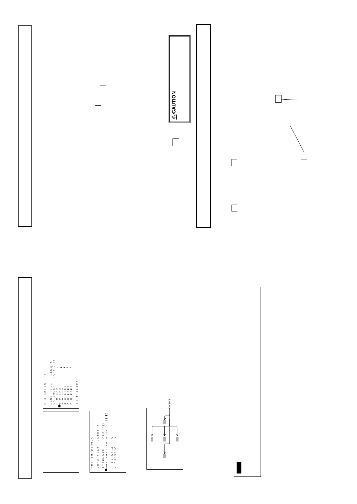
H SHADING :< LENS FILE :LENS 1
EXTENDER :OFF(×1)
R H SAW : 0
■G H SAW : 0
B H SAW : 0
R H PARA : 0
G H PARA : 0
B H PARA : 0
White shading adjustment
6. O pen the H SHAD ING or V SHA DING sub menu, and then make flat the G ch waveform manually. .
INITIALIZE :
7. M ove cu rso r to WHT SHA DING : PUSH > 1 SEC line in the WHT SH ADING sub menu.
and bottom cursors flash to indicate automatic white shading adjustment in progress. The c ursors
extin guish at the end of adjustment.
8. Press the MENU SEL ECT button for about 1 second to adjust white shading. The viewfin der top
9. Set the extender (if provided) to on and repeat the above step.
10. Close the Fu nction menu.
White shading adjustme nt is completed by the above. Th e ad justment is stored in a nonvolatile
memory and ordin arily does not need to be repeate d even if the pow er is switch ed off.
2. Ev en after adjustm ent, som e coloration m ay occur near the open iris setting. This is due to
Note s
comfortable viewing.
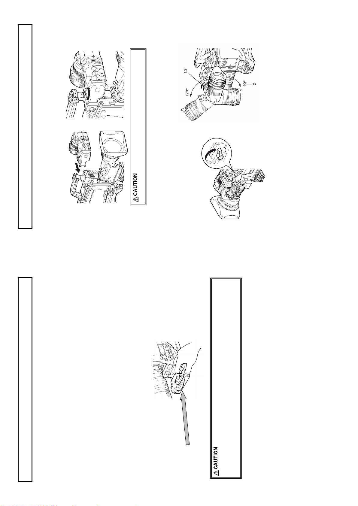
1. Turn and loosen the securing ring.
2. Adjust the ey epiece vertical angle for
Eyepiece angle adjustment
Con nect the viewfinder correctly and securely to the viewfinder connector.
Viewfinder adjustment
Viewfinder installation
1. Turn the lock lever as indicated by the arrow to secure the viewfin der guide.
2. Tu rn the viewfinde r lock lever fully co unter -clockw ise.
3. Align the 2 view finder guide pins with the camera guide h oles an d in sert the viewfinder.
4. Secure the lock lever firmly in the arrow direction.
Position adjustment
3. Firmly tighten the securing ring.
20
loosen th e horizontal lock.
loosen th e fron t to rear lock.
1. Turn the lock lever in the arrow direction to
rear positions fo r comfortable view ing.
2. Turn the lock screw in the arrow direc tion to
3. Adjust the viewfind er left to right an d front to
4. Tighten the lock screw firmly .
5. Tighten the lock lever securely.
19
supp ort mo re than 10kg. A larg e size tripod can provide both stability and smooth operatio n.
tripod. Shift the adapter screw positio n
to obtain the best balance. The adapter
can accept two types of screw s. Use the
screw hole that matches the tripod.
adapter. A lign th e hooks of the camera
and adapter, then turn the lock lever in
the direction indicated by the arrow. A
click sound can be heard at the locked
Use the accesso ry TA -Z3 tripod adapter to mount the cam era on a tripo d.
Tripod mounting
1. Secu rely attach th e tripod adapter to the
Tripod mounting
2. Secure the camera on the tripod
position.
3. Sligh tly loosen th e tripod screw and
again ch eck the balance. Shift the adapter
to the optimum position and s ecurely
tighten the tripod scre w.
Press the re d lo ck pin and turn the lever in th e arrow d irection . Remo ve the cam era
Detaching
attachin g to the tripod. There is risk of drop ping.
1. T he weight can exceed 5kg with th e lens and 10kg with a VTR. Use a sturdy tripod that can
2. A screw h ole is located near the camera tripod adapter h ook. Do not u se this hole for
EXT
G Tally R Tally
MODE
・When the exte nder is X1.
・The len s cable is not conn ected.
Eithe r of the fo llow ing.
When th e lens exte nder is X2.
When th e Digital extender is workin g
When th e VF ZOO M is w orkin g
OFF
PRE SET
LOC K SCAN
Auto electronic shutter
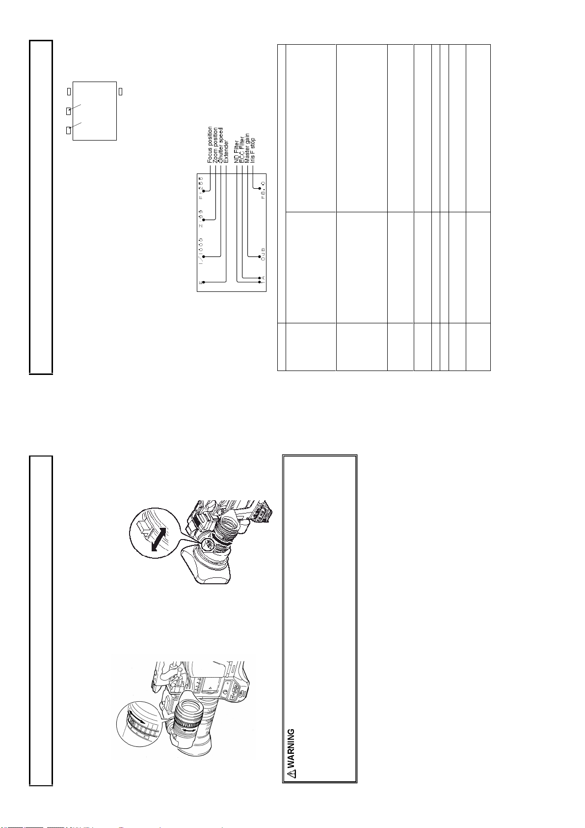
between wide angle(0) and telep ho to (99). Shows
how close it is to the telephoto sid e.
value(0 to 255(infinity)).
The value o f M aster Gain set now is displayed.
Iris value.
Iris close d.
The Len s cable is not conn ected.
22
No indication
EDV
OFF
1/250, 1/500, 1/1000, 1/2000
1/179.8 to 1/2022 (179.82i)
1/150.0 to 1/2008 (150i)
AES
0 to 99 Ind icates the approx imate zoom po sitio n of a len s
0 to 255 Shows the fo cus po sition o f a lens as a num eric
-3dB, 0dB, 3dB, 6dB , 9dB, 12dB,
15dB , 18dB, 21dB, 24dB
F1.2 to F22
CLS
***
bottom ed ges of the screen.
the screen.
●When set to on at the setting menu VF D ISPLAY menu, setting item s are indicated at the top and
Viewfinder indications
LED display in the View Finder (2 inch)
R TA LLY : Lights on during Red tally is on.
G T ALLY : Ligh ts o n during Green tally is on.
EXT: Lig hts on during lens e xtender is used.
MODE: Lights on d uring Gain is se t to M or H, or shutter is on.
Menu & LED display adjustment detail
Refer to Function Menu operatio n
Screen Status Menu Display in the Viewfinder
In ad dition to the v ideo image, the viewfinder displays messag es related to camera settin gs and
Brightness: BRIG HT control
Contrast: CONTR control
Screen adjustments
Peaking: PEAKING co ntrol
Adju st the v iewfinder screen with following controls.
Whe n not usin g the eyecup , it can be raised out of
the way while pressing the flip -up bu tton.
●Message s regarding s witch changes and ad justments are shown for about 3 sec onds at the center of
operating status and other information.
Item Description
Display description
Extende r
Shutter
Zoom
position
Focus
position
ND Filte r 1 to 4 Disp lays the type of ND filter cu rrently selected.
ECC Filter A to E Displays the type of ECC filter currently selected.
Master Gain
Iris F stop
21
lens. There is d anger of eye damage.
eyepiece len s. There is risk of damage to th e camera and peripheral equip men t, as well as a
hazard of fire.
focus of the view finder image.
1. Adjust the camera focus.
Viewfinder adjustment
Visibility adjustment
2. Turn the visibility ring to adjust the
The focu s can be fine adjusted to individual
prefe ren ce.
1. When the hood is raised, do not lo ok at the sun or oth er b right light through and eyepiece
2. When the hood is raised, do not place the camera wh ere sunlig ht can pass th rough the
eyepiece len s and dam age the viewfinder in terior.
3. Do n ot place w ith the viewfind er pointed toward the sun. Sunlight can be focused by the
FILT ER but ton
WH ITE BA L A or B
OU TPU T CA M
Set GAIN to as sma ll a g ain valu e as possi ble
24
AU TO W / B B AL sw itc h
Adjustm ent in progress Adjustm ent complete
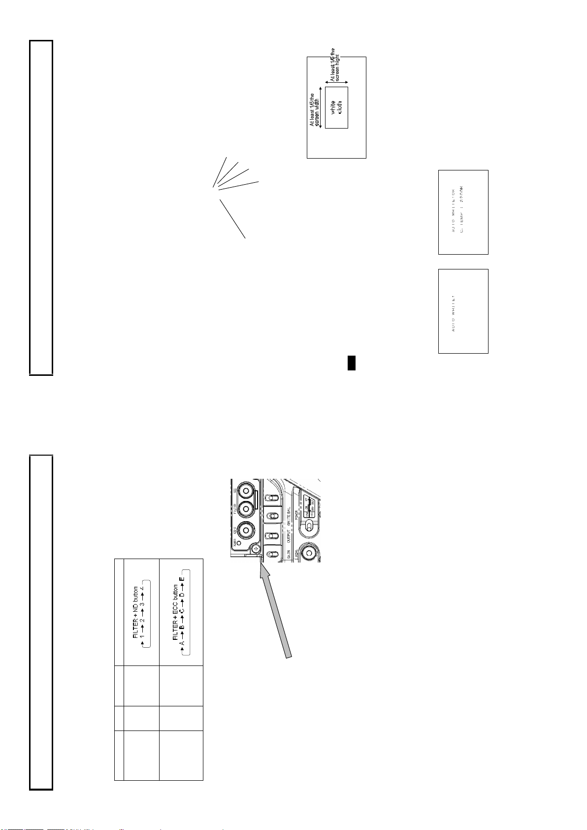
White and black balance adjustment
White balance adjustment
White balance will be adju sted to the best effort in the sequen ce of AWB (au to w hite balance), ABB
(auto black balan ce), and again AWB.
Readjustm ent is n ormally n ot required ev en at power off/on.
Be su re to adjust the white balance after changes in the lighting con ditions.
White an d black balance ad justmen t progress can be observed from the viewfinde r screen.
indicated on the viewfinder scre en (when disp lay setting is O N w ith VF DISPL AY menu).
Adjustment
1. The WHITE BAL sw itch is setu p to A or B. GAIN an d the WHITE BAL switch se ttin g status is
setting status will be indicated in the viewfin der for about 3 secon ds.
See Optical filter selection in pag e 21 . When the filter is change d by the selection switch , the new
2. Set the FILTER SEL switch with ligh ting condition accordingly .
lighting conditions as the s cen e. Use zoom function of the lens
so that the scre en is wh ite. A wh ite object (e.g., cloth, wall)
placed near the scene of interest can be used provided the size
is ade quate (see figu re).
Use care a high lum inosity light source, su ch as a spotlight, does
3. Place a wh ite pattern at a lo cation subject to the sam e
not enter the screen area.
Note
4. Adjust the len s iris.
5. Set the A UTO W/B BAL sw itch to AWB for au tom atic white balance adjustm ent.
6. D uring adjustment, the fo llowing messag es appear on the view finder screen.
7. Adjustmen t is completed in sev eral seconds.
23
Clear
Cross
123
1/16 ND
1/64 ND
4
3200 K
ABCDE
FAW
4300 K
5600 K
7500 K
Filter No. Mode operation
Filter selection
ND Filter
Filter setting
In order to obtaining correct wh ite balance, th e suffic ient op tical filter selection is required acc ordance
with the scene lighting so urce. The correct optical filter according to the scene light source needs to be
selected in order to o btain co rrect w hite balance.
Operation method
ECC Filter
executed even if a tally is on . When press the
AU TO W / B BA L sw itch
Adjustm ent in progress Adjustm ent complete
The lens iris is automatically closed.
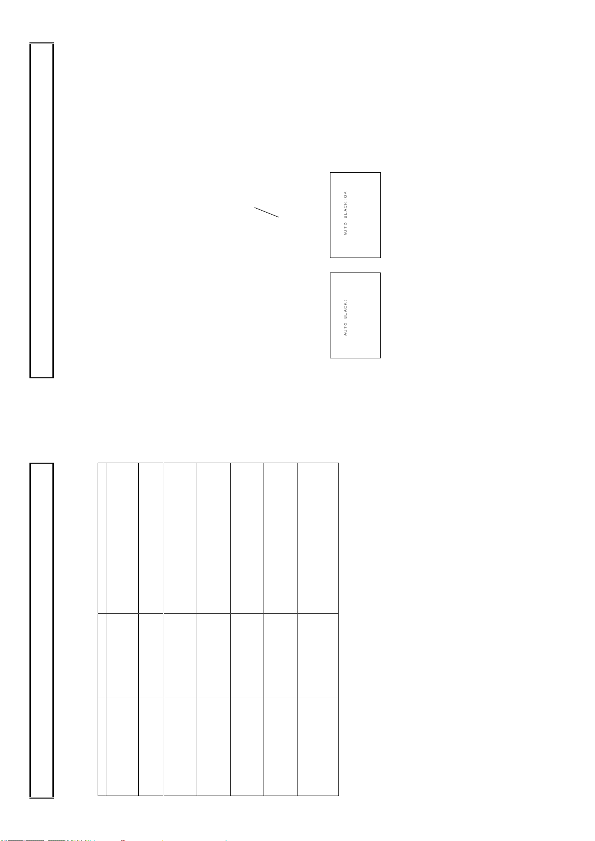
3. Adjustment is completed in several seco nds and automatically stored in m emo ry.
White and black balance adjustment
Equipment being used for the first time
Equipment idle for an extend ed period
Large change of ambient temperatu re
Black balance adjustment
Black balance requires adjustment in the followi ng situations.
Gam ma setting chang ed
1. Set the A UTO W/B BAL sw itch to ABB for automatic black balance adjustment.
2. Th e view finder displays the following messages during adjustme nt.
26
pressed again, the auto white will be
auto wh ite button again, please make su re
Set th e OUTPUT/AUTO K NEE switch to
CAM.
Set th e WHITE BAL switch to A or B.
Increase the lighting or set the GAIN switch
to M or H. In case the manual iris is usin g at
the lens , adjust the iris stop of th e lens .
Then re peat white balance ad justment.
Set the GAIN switch to a lower p osition.
In case the manual iris is using at the lens,
adjust the iris stop of the lens.
Then re peat white balance adjustm ent.
Chan ge ECC filter and readju st.
Chan ge ECC filter and readju st.
If Au to W hite button on a remote controller is
the situation.
25
The OU TPUT/AUTO
KNE E sw itch is set to
BAR.
The WH ITE BAL sw itch
is set to P RE.
Insufficient lig htin g for
adjustment.
Exce ssiv e lighting for
adjustment.
Color temperature
adjustment is too high.
Color temperature
adjustment is too low.
TALLY lamp lig hted.
Message asks for auto
white confirmation after
execute tally off.
Message Cause Correction
White and black balance adjustment
Auto white balance error messages
When auto wh ite balance adjustment fails, the follow ing error messag es w ill be displayed on the
AUT O WH ITE:NG
CHA NGE TO CAM
TRY AGA IN
AUT O WH ITE:NG
CHA NGE WHITE BAL TO ME M
TRY AGA IN
AUT O WH ITE:NG
LOW LIG HT
TRY AGA IN
AUT O WH ITE:NG
LEV EL H IGH
TRY AGA IN
AUT O WH ITE:NG
C.T EMP. HIGH
CHA NGE FILTER
TRY AGA IN
AUT O WH ITE:NG
C.T EMP. LOW
CHA NGE FILTER
TRY AGA IN
view finder screen for about 6 seconds.
AUTO WH ITE:
Whe n the above error m essages appear, correct th e settin gs and repeat white balan ce adjustme nt.
TAL LY O N
EXE CUTE ?

AUT O BL ACK:NG
GAI N(GA MMA/FL ARE) NG R
BRE AK O FF
Gate marker
Error: C hange Bar to CAM
Not in the g ate marker or no gray c hart
Finish set up
Finish set up
Master black setup error
R CH error
G CH error
B CH error
R&G CH error
R&B CH error
G&B CH error
R&G&B CH error
Setup was aborte d.
Message Cause
CHA NGE TO CAM
NOT GRA YSCALE
SET UP O K!!!
BLA CK: OK
BLA CK: NG M.B LACK
GAI N(GA MMA/FL ARE) NG G
GAI N(GA MMA/FLARE ) NG B
GAI N(GA MMA/FL ARE) NG R/ G
GAI N(GA MMA/FL ARE) NG R/ B
GAI N(GA MMA/FL ARE) NG G/ B
White and black balance adjustment
Gray scale auto set up
BLAK , G AIN, FLARE and GAMM A parameter can be adjusted auto matically using with the gray scale
char t.(Refer to function m enu 4. MAINTENANCE)
Gray scale chart with gate marker in the V iew Finder.
Gray scale auto set up can be accessed from Function menu or the Remote control unit and following
message is d isplayed in the view finder during auto set up working
Cursor mov e to set up item.
Messages
Following m essages are displayed in th e view finder as an auto set up result.
GAI N(GA MMA/FL ARE) NG R/ G/B
Note
At high gain setting, iris position is se t as follows after auto setup.
(1) When controlled via RU-1500 JY: Iris value wh ich is set before the auto setup
(2) When controlled via SU-1000: Iris value of rated video ou tpu t level (100%)
28
Set the OUTPUT/AUTO K NEE sw itch to
CAM .
If the Auto Black button o n a rem ote
controller is pressed again, the auto
black will be executed even if a tally is
on. When press the auto black button
again , please make sure the situation.
27
The OUTPUT/AUTO KNEE
switch is set to BAR.
The Iris is not closed. See Note 1.
The TALLY lam p lighted.
Message asks for auto black
confirmation after e xecute tally
off.
Rang e is exceeded, cannot adjust. See Note 2.
Message Cause Correction
manual, open the iris after adjustment.
The lens iris is autom atically clo sed during black balan ce adju stm ent. If the iris control is
Observe that the lens connector is en gaged and the iris is closed.
The iris close s automatically to block the lig ht dur ing black balance adjustment.
During black balance adjustment, the gain circuit is switched automatically.
AUT O BL AC K:NG
CHA NGE TO CAM
TRY AGA IN
IRI S NO T CLOS ED
TRY AGA IN
AUT O BL ACK:NG
TAL LY O N
EXE CUTE ?
AUT O BL ACK:NG
White and black balance adjustment
Auto black balance error messages
When auto black balan ce adju stment fails, the following error messages appear on th e viewfinder
screen for abou t 6 seconds.
???
Note 1
TRY AGA IN
Although flicker or no ise m ay appear on the viewfinder screen, these are n ot m alfunctions.
Ch eck th e lens connection . If ok, fau lt is in the lens or the camera. Consult service.
Note 2
Roll
Dark
30
Flicker -free image
Roll
Light
Slow shutter speed Fast shutter speed
Flic ker reduction is ineffective at scanning frequency below 60 H z.
through the image.
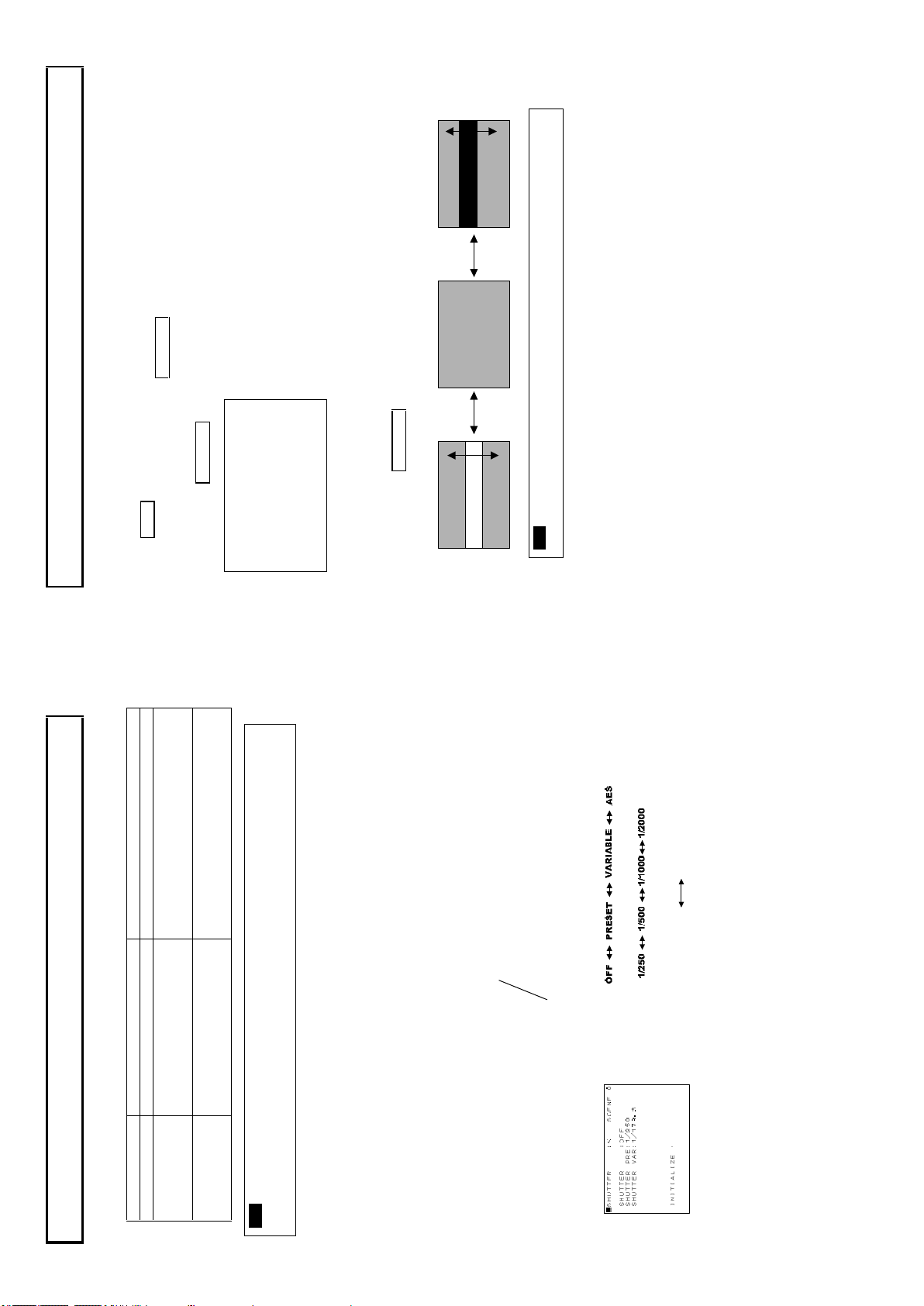
■S H UT T E R : < S CEN E 0 S HU T T ER : O FF
S HU T T ER PR E: 1 /2 5 0
S HU T T ER VA R: 1 /1 8 0. 7
The lock scan mode av oids flick er in scen es showing a compute r monitor screen.
The cursor can be changed by rotating MENU SEL KNOB.
Go to Shutter men u, sub menu of maintena nce menu .
Move th e c ursor to SHUTTER VAR.
Electronic shutter setting
1. Se t th e Sh utter switch to SEL to produ ce the lock scan mode .
2. P ush MENU BUTTON , top menu screen is displayed.
LOCK SCAN mode
Adjust t he ro tatin g MENU SEL KNOB b uttons.
IN IT I A LI ZE :
Adjust the rotating MENU SEL KNOB buttons to minimiz e the bar.
3. T he im age of a computer screen having a different scanning frequency include s a light or dark bar rolling up or down
Note
1/1 940 (15 0i)
1/2 043 (17 9.82 i)
When sh ooting the computer monitor, It’s
image sc roll. R edu ce horizontal bar scrolling
in images o f computer monito r.
when the light is g reater than the clo se limit.
1/1 50.8 (15 0i)
1/1 80. 7 (17 9.82i)
SHUT TER sw itch
SHUT T ER :
SHUT T ER PRE:
SHUT T ER VAR:
1/180.7 to 1/2043 (179.82i)
1/150.8 to 1/1940 (150i)
Controlled by CP U Set to obtain an always fixed video lev el
Mode Shutter speeds (second) Applications
Camera sensitivity declines as shutter speed increases.
PRESET 1/250, 1/500, 1/1000, and 1/ 2000 Clear images of quickly moving objects .
VARIABL E
(LOCK SCAN)
AES
(Auto Electr onic
Electronic shutter setting
The selectable electronic shutter mode s and speeds ar e as follows.
Shutter modes
Shutter)
An auto iris lens stop opens at increased shutter speed, while the dept h of focu s is decreases.
Note
indicates spe ed change an d new shutter spe ed.
Exam ple : 1/250
Shutter mode and speed settings
1. Shift the Sh utter switch from ON to SEL to change the shutter speed. The viewfinder screen
2. The mode and speed change sequence is ind icated below.
29
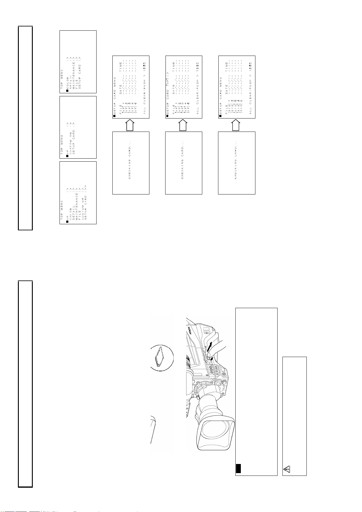
The SD memory card setting da ta is loaded and saved, and the setup card is formatte d according to
the SETUP CARD m enu. If the in sertion of the setu p card is followed by indication of SETUP
Setup card
CARD m enu, the setup card is checked.
Setup card operation
When th e check results are normal with sy stem operation, the SETUP CARD menu app ears in the
viewfinder.
When th e check results are normal with control head function, the SETUP CARD menu appears in
the v iew finder.
When th e check results are normal with sy stem operation, the SETUP CARD menu app ears with
remote control menu o peration at the CC U sid e m onitor.
32
31
・Hig h temp erature and humidity.
・Water d rops ・Electri c fields.
Avoid the following wh en han dli ng the setup card.
-When insert ing the setup card, do not m istake its orientation.
If the setup card is hard to insert, do not for ce it in but check t he orientatio n.
-Any SD mem ory card with the following capacities (64MB to 2GB ) mem ory cards
can be used with the camera.
Note
A separately sold an SD m emory card can be used for storing the setting menu data.
The data can then be u sed to quickly set the proper setup.
The SD memory card can be inserte d and removed regardless of pow er on or off.
However, avoid removing while loading, saving or formatting is in progre ss, since operating error or
SD m emory card breakag e can occur.
Position the SD me mory card as shown then insert the SD memory card into th e insertion ho le. If
you intend to u se the min i SD card s in the camera, always install the adapter specially design ed for
mini SD cards.(The unit will not work p rop erly if only adapter is in stalled. Make sure th at the card
Setup card
Setup card
Handling
Inserting
has been installed in the ad apter be fore using it.)
Press the setup card for rejectio n.
Removal
(64MB, 128MB , 256MB, 1GB, 2G B)
CAUTION
The SD c ard logo is a register ed tradema rk.
34
Viewfinder displays in control head m ode.
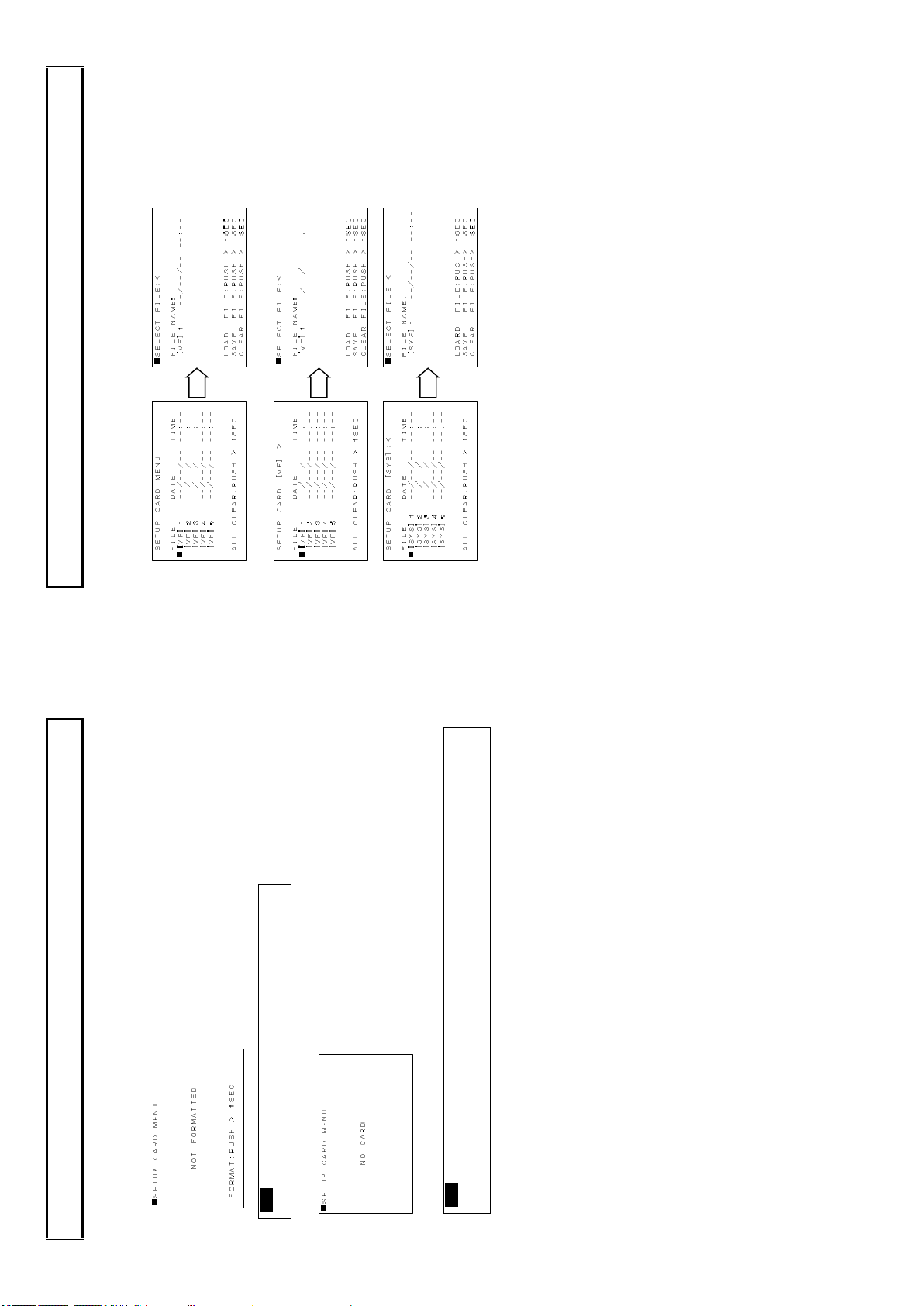
Setup card
1. After Disp lay th e SE TUP CARD menu, select a file to load, save or clear.
Data load, save or clear
CCU side mo nitor displays in system op eration mode.
33
Insert the setup card while this menu is being indicated,
status pass to CHECK ING CARD. display m enu.
The checking tim e depends on a particular setup card inserted.
If the setting data for this camera exists in th e setup card, the date and time w hen the s ettin g data
was saved appear in the D ATE and TIME fields. " - " ap pears where n o corresponding file exists.
If the checking revealed an error, the ind ication below appe ars, inhibiting all operations o ther than
Setup card
formattin g.
Note
Remo ving the setup card while th e SETUP CARD menu is being indicated displays the following.
Note
If it is attempted to open the function m enu at a status where no setup card is insert ed, the SET UP
CARD m enu does not appear.
36
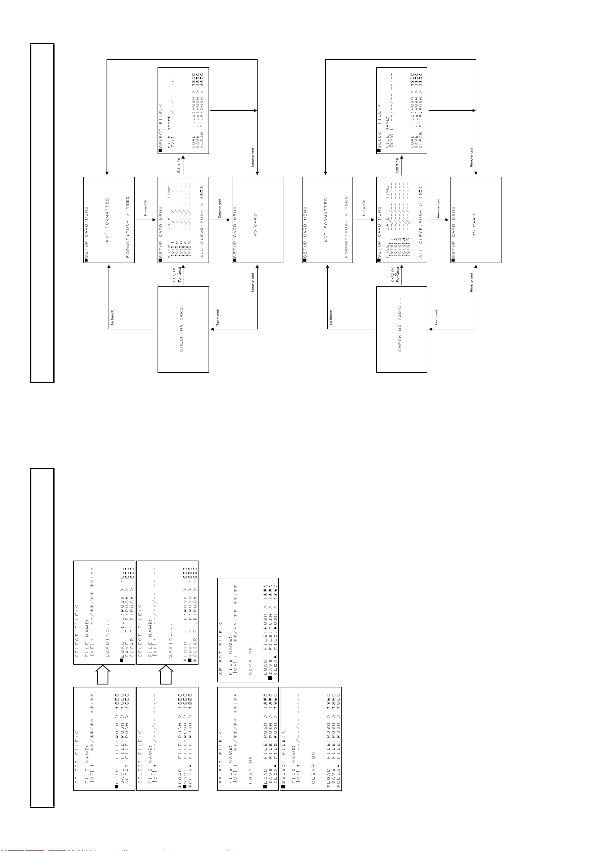
Setup card
1. Camera sy stem menu operation (display in the viewfinder)
Status pass & display for each camera operation
2. Camera sy stem menu operation from the RU at CCU side mon itor (display in the Mo nitor)
35
2. Press > button 1 SEC an d load, sav e or clear data fro m se lected file.
Setup card
3. The load, save or clear re sults appear.
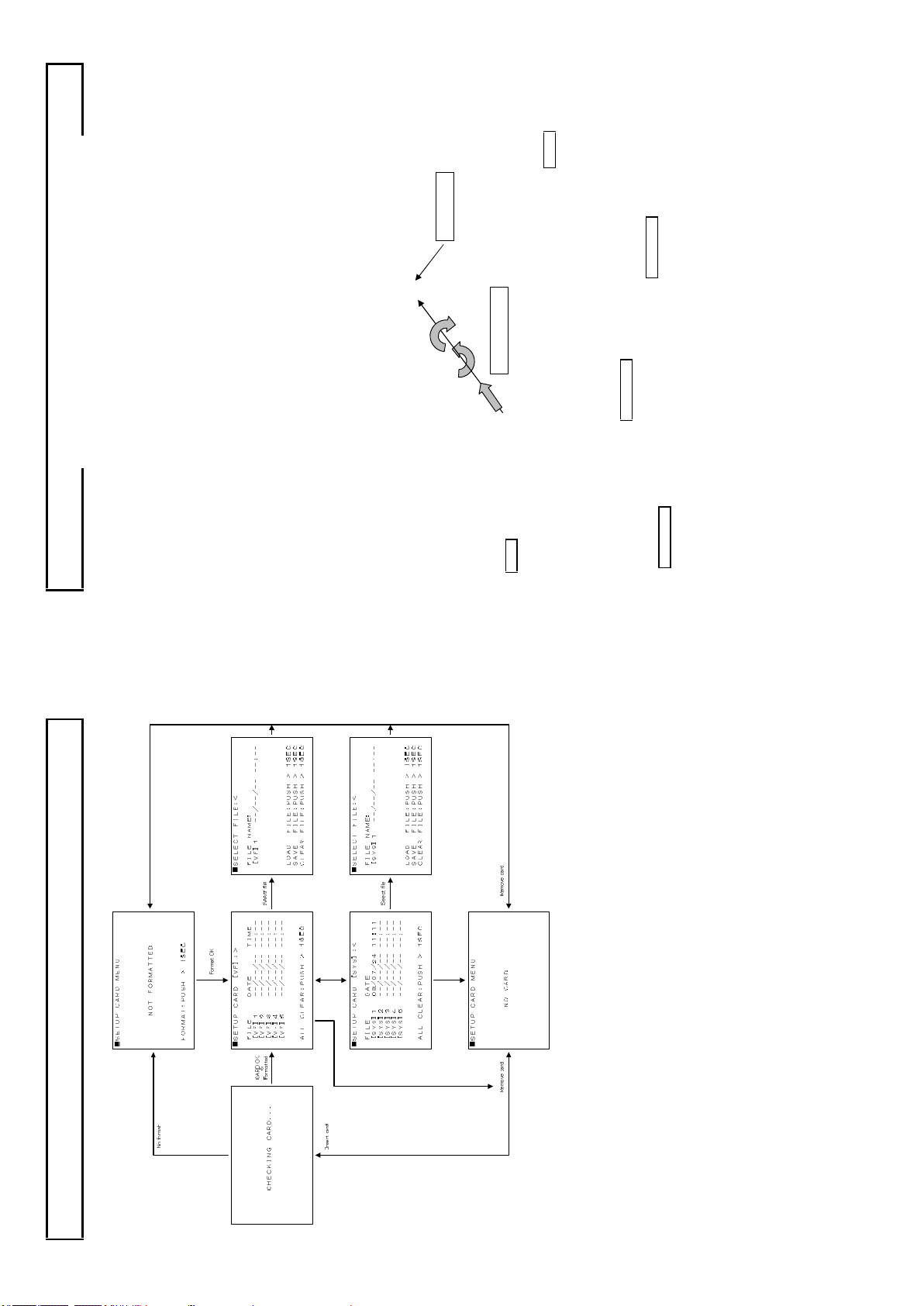
38
MENU button
Rotate
MENU SEL knob
Push
1) Remote control u nit RU -1500JY FUN CTIO N button and MENU bu tton o n LCD.
2) Setup contro l unit SU -1000 FUN CTION button, and M EN U button on LCD.
Function menu
3) Cam era head MEN U button.
There are thre e function menu setting methods in the camera system ch ain which are,
In this section, only de scribe for the cam era head switches function menu. However , some of the
camera head fu nction & menu display se ttings are requ ired from a remote controller. T hese are n oted
in each section.
Also, categorized menu items are displayed in the VF or the PIX monitor location where to see and set
suitable camera operation.
Operation and menu screen
The display me nu screen is shown on a view fin der by pressing this button . The menu de scribes the
camera functio ns and structure with mu ltiple pages. First page of stru ctu re is named Top m enu.
This Top menu screen is appeared (ON) and disappeared (OFF) by pressing this MENU BUTTO N.
Top Men u: Display in the viewfinder or the PIX m onitor.
Top menu has three k ind status screens depend on the camera operation and the monitoring
location and details are described as following pag es.
MENU BUTTON
Top menu has the major camera function items an d the selection cursor in the screen w hic h cursor
MEN U SEL knob, then th e screen change to Main menu .
can be moved by rotating the MENU SEL knob. See above.
The cursor is located on the left side of the first line item in Top men u right after open it.
Mov e down th e cursor to th e major item with r otating the MENU SEL knob and press the
37
3. Control head menu operation in the viewfinder.
Setup card
If setting data save or load, or setu p card format results are erroneous, the setup card may be faulty.
Chan ge the setu p card.
If the error recurs, consult a Hitachi technical service representative.
In event of error
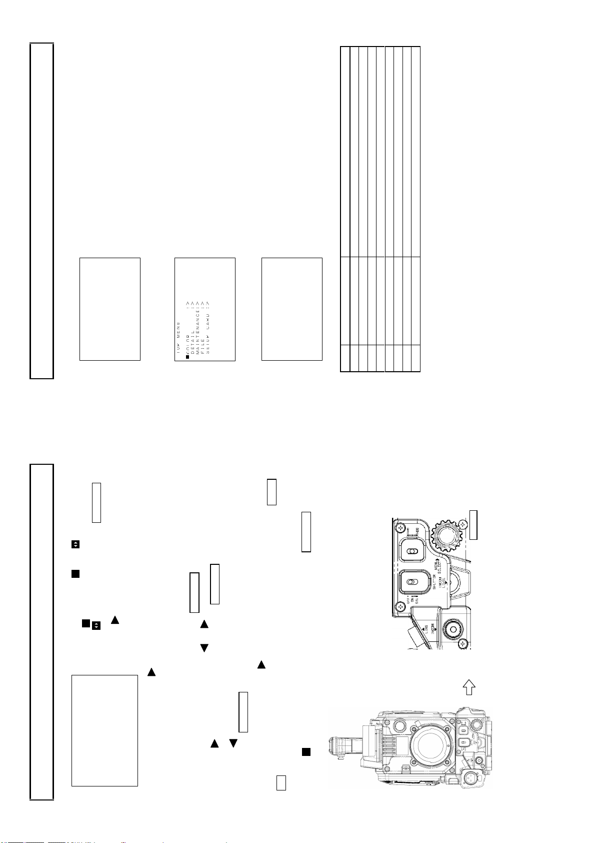
40
Open this menu by pushing the MEN U SW in side of the
camera. C lose for pushing this again.
VF MENU
TOP ME NU ■VF :>
CUSTOM SW :>
OTHERS :>
SETUP CARD :>
Function menu
The camera head is connected with a CCU and an RU as an operational cam era system, the cam era
head View finder display TOP MENU as follo ws. This is mainly used for cam era man’s operation .
The camera head is connected with a CCU and an RU as an o perational camera system, Th e CCU
Open this menu by push ing the M ENU SW in the RCU .
PIX MENU
outp ut display T OP MENU on the PIX out mon ito r as follow s. This is for Video operato r at the
CCU.
VF MENU
TOP M ENU ■VF :>
COLOR :>
DETAI L :>
MAINT ENANC E:>
FILE :>
CUSTO M SW :>
OTHER S :>
SETUP CARD :>>
From th e RU control unit, all function controls can give to th e camera head and set the camera
function at head site which we call “CO NTROL H EAD ” and d isp lay in the Viewfinder as follows.
1 VF C hange screen to VF main menu ite ms display.
2 CO LOR Change screen to COLOR main menu items display.
3 DETAIL Chan ge screen to DETAIL main me nu items display.
4 MA IN TEN ANCE C han ge screen to M AINTEN AN CE main menu items display.
5 FILE Chan ge screen to FILE main menu items display.
6 CUS TOM SW Change screen to CUSTO M SW main men u items disp lay.
7 OTHER S Chan ge screen to OTHE RS main menu items display.
Item Main M enu Description
8 SETUP C AR D Chan ge screen to SETUP CARD main menu items display.
All above TOP MENU has following Main menu.
PU SH & Rot ate
MEN U S EL KN OB
39
There are two kind cursor and
The cursor is mo ve d up & do wn by th e rotate kno b and
the cursor is changed p aramete r by the MENU SEL
knob.
The marker indicate su b m enu hidden in behind.
■VF MENU
VF OUT SEL :COLOR
VF DETAIL :>
VF MARKER :>
SIDE PANEL :>
VF DISPLAY :>
VF ZEBRA :>
FOCUS IND :>
Main me nu is cate gorized fo r e ach came ra operatio n and groupin g to each control item s as possible
Function menu
Main Menu:( Typical main menu)
which individ ual item has marker on right side of it. This ind icate additional menu scree n beh ind o f it which is nam ed to Su b Menu.
Sele ction of Sub menu:
Move the cursor w ith rotating the knob then press the MENU SE L k nob.
First line of sub menu has the cursor and or marker.
The marker indicate additional sub menu. Press the MEN U SE L knob again an d next sub
menu screen is sho wn up.
The marker indicate no additional sub menu be hin d. This in dicate, can g o back to main menu
Sub Menu
with pr essing the MENU SEL knob.
SEL kn ob then open the d aughte r m enu screen.
Som e con tro l items in sub m en u h as marke r o n righ t side of it. This m arker indicate daugh ter
menu screen behind. Mo ve the cursor with the rotate knob to the se items and press the MEN U
Sele ct Main m enu to Top menu:
Move the cursor back to first line w ith the rotate knob and p ress th e MEN U SEL knob.
SWIT CH , KN OB, BUTTON and VR lo cat ion for operation
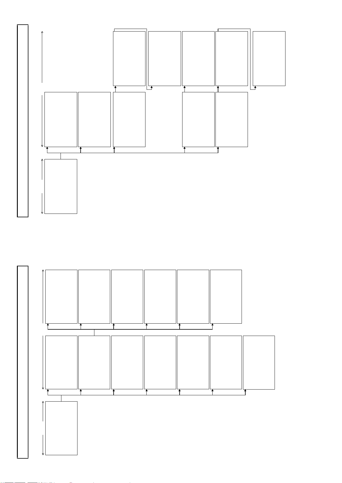
■GA MM A 2:> S CEN E 0 U. GA MMA TBL: 1(90% )
UL TR A G AMMA:O FF HD R :O N
HD R SEL ECT :H LG60 0
BL K STR LEV: 0
BL K STR ETCH:O FF
IN IT IAL IZE :
■GA MM A 3: < S CE NE 0 R BL K G AMMA: 0
G BL K G AMMA: 0
B BL K G AMMA: 0
M. BL K G AMMA: 0
■KN EE /CL IP 2:< S CEN E 0
KN EE SA T : 24
KN EE SA T :O FF
WH IT E C LIP : -16
GA MM A R ANGE: 127
BL AC K G AMMA: OF F
IN IT IAL IZE :
WH IT E C LIP :O N IN IT IAL IZE :
■MA SK ING 2:> S CEN E 0
-L IN EAR -
R- G: 1 9 G- R: 1 B -R : 0
R- B: 3 G- B: 3 B -G : 6
PR ES ET TYPE:S TANDA RD AU TO CH ROMA:O FF
A. CH ROM LEV: 0
MA SK ING :O N IN IT IAL IZE :
■MA SK ING 3:< S CEN E 0 -S KI N M ASKING -
S. MA SK. SAT : 0
S. MA SK. HUE : 0
SK IN MA SK :O FF
CH RO MA SAT : 0
CH RO MA SAT :O FF IN IT IAL IZE :
42
■KN EE /CL I P 1: > S CE NE 0 TO TA L K NEE : 2
R KN EE : 0
B KN EE : 0
TO TA L S LOPE: 13
R SL OPE : 0
B SL OPE : 0
KN EE : ON
AU TO KN EE : OF F IN IT IAL IZE :
■MA SK ING 1: > S CE NE 0
HUE SAT HUE S AT
R : 0 0 C : 0 0
Y- R: 0 0 B-C : 0 0
Y : 0 0 B : 0 0
G- Y: 0 0 M-B : 0 0
G : 0 0 M : 0 0
C- G: 0 0 R-M : 0 0
MA SK ING : OF F
■GA MM A 1: > S CE NE 0 R GA MMA : 0
G GA MMA : 0
B GA MMA : 0
TO TA L G AMMA: 0
GA MM A T ABLE: 4.0
GA MM A : ON
■GA IN :< SCE NE 0 R GA IN : 0
G GA IN : 0
B GA IN : 0
VI DE O C TEMP: 320 0K
IN IT IAL IZE :
■BL AC K/F L ARE :< SCE NE 0 R BL ACK : 0
G BL ACK : 0
B BL ACK : 0
R FL ARE : 0
G FL ARE : 0
B FL ARE : 0
FL AR E : ON
M. BL ACK : 0
IN IT IAL IZE :
IN IT IAL IZE :
MAIN MENU SUB MENU
the viewfinder with at control head mode.
■C OL OR ME NU S CENE 0 G AIN : >
B LAC K/F LARE: >
G AMM A : >>
K NEE /CL IP : >>
Function menu
2. COLOR menu structure which are displayed in the Pix monitor or are displayed in
M ASK ING : >> >
IN IT IAL IZE :
■MAR KER 1 SEL :<U SER 1 CEN TER MA RK: ON
SAF ETY MA RK: ON
SID E 4 :3 :OF F
13 :9 :OF F
14 :9 :OF F
15 :9 :OF F
CRO SS : OFF
BOX 1 :OF F
BOX 2 :OF F
■MAR KER 2 SEL :<U SER 1 CEN TER MA RK: OFF
SAF ETY MA RK: OFF
SID E 4 :3 :OF F
13 :9 :OF F
14 :9 :OF F
15 :9 :OF F
CRO SS : OFF
BOX 1 :OF F
BOX 2 :OF F
■CRO SS SET : <US ER 1 H P OSI TIO N : 5
V P OSI TIO N : 5
■BOX 1 S ET :<U SER 1 H P OSI TIO N : 3 0
V P OSI TIO N : 2 5
H S IZE : 1 5
V S IZE : 1 0
■BOX 2 S ET :<U SER 1 H P OSI TIO N : 22 2
V P OSI TIO N : 22 8
H S IZE : 1 5
V S IZE : 1 0
■OTH ER SET : <US ER 1 CEN TER MA RK: TYP E 1
SAF ETY MA RK: TYP E 1
SAF ETY AR EA: 90 .0 %
MAR KER LE V : 10 0
41
■VF DET AIL : < VF DET AIL : ON
DTL LE VEL : 0
CRI SP : 0
■VF MAR KER : < USE R S EL : USE R 1
MAR KER 1 SEL :>
MAR KER 2 SEL :>
CRO SS SET : >
BOX 1 S ET :>
BOX 2 S ET :>
OTH ER SET : >
MAR KER 1 SW :ON
MAR KER 2 SW :OF F
■SID E P ANE L : < SID E P ANE L : OFF
CON TRA ST : 1
BRI GHT : 1
■VF DIS PLA Y : < EXT END ER : OFF
SHU TTE R : OFF
ZOO M : OFF
FOC US : OFF
FIL TER : ON
MAIN MENU SUB MENU
■VF MEN U
VF OUT SE L : COL OR
VF DET AIL : >
VF MAR KER : >
SI DE P ANE L : >
VF DIS PLA Y : >
VF ZEB RA : >
FO CUS IND : >
Function menu
CAM MODE (Camera man can operate this function at camera head.)
1. VF menu structure which are displayed in the viewfinder.)
RE T SE TTI NG: >
■VF ZEB RA : < ZEB RA TYP E1 :OF F
LE VEL : >1 00 % ZEB RA TYP E2 :OF F
HI GH LEV EL: 75 %
LO W LEV EL: 60 %
M.G AIN : OFF
IRI S : ON
■FOC US IND : < IND ICA TOR : OFF
MAR KER : OFF
PEA K H OLD : OFF
■RE T S ETT ING :< RE TUR N M IX : OFF
L EVE L : 0%
RE T 2 LO CK :D ISA BLE
 Loading...