Hitachi SJ Series User Guide

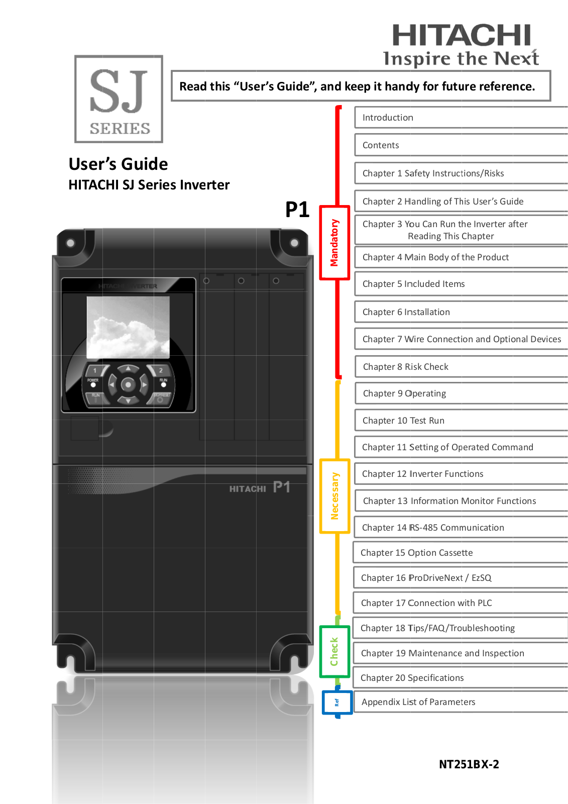
Hitachi SJ Series User Guide

Read this “Us er’s Guide ”, and ke ep it hand y for futu re reference.

User ’s Guid e

HITAC HI SJ Series Inverter

P1

<![if ! IE]>

<![endif]>Mandatory

<![if ! IE]>

<![endif]>Necessary

<![if ! IE]>

<![endif]>Ref Check

Introductio n

Contents

Chapter 1 S afety Instruc tions/Risks

Chapter 2 Handling of Th is User’s Guide

Chapter 3 You Can Run the Inverter after Reading This Chapter

Chapter 4 M ain Body of the Product

Chapter 5 In cluded Items

Chapter 6 In stallation

Chapter 7 W ire Connect on and Opti onal Devices

Chapter 8 Risk Check

Chapter 9 O perating

Chapter 10 Test Run

Chapter 11 Setting of Op erated Com mand

Chapter 12 Inverter Fun tions

Chapter 13 Information Monitor Fun ctions

Chapter 14 RS-485 Com munication

Chapter 15 Option Cassette

Chapter 16 ProDriveNext / EzSQ

Chapter 17 Connection w ith PLC Chapter 18 Tips/FAQ/Troubleshooting

Chapter 19 Maintenance and Inspection

Chapter 20 Specification s

Appendix Li st of Parame ters

NT2 51BX-2

Chapter 1

Safety Instructions/Risks


1

Chap ter 1 Safety Instructions/Ri sks

Contents

1

.1

What this Chapter Expla ins .....................................

1-1

1

.2 Types of W arnings ...................................................

1-1

1

.3

Descriptio n of Safety Symbols.................................

1-2

1

.4

Cautions ..................................................................

1-3


1.4.1 Cautio n! ............................................................

1-3


1.4.2 Precautions for installation ...............................

1-4


1.4.3 Precautions for Wiring ......................................

1-5


1.4.4 Precautions for Run ning and Tes Running ......

1-6


1.4.5 Precautions for Maintenance/


Daily Inspection ..............................................

1-7


1.4.6 Precautions for disp osal ...................................

1-8


1.4.7 Other Cautions .................................................

1-9

1

.5

Examples of Caution Labels..................................

1-10

1

.6

Response to European Directive (CE ....................

1-11


1.6.1 Cautio n for EMC


(Elec tromagnetic Compatibility) .....................

1-11


1.6.2 Cautio n for Machin ery Directive


(Functional Safety) .......................................

1-13

1

.7

Response to UL standar ds ....................................

1-14

1.1 What T his Chapter Explain s

his chapter inncludes instructions for inst allation, wiring ,

o peration, maintenance, inspection and use of the inverter.

Be sure to read this User’s Guide and appended

d ocuments thooroughly befor e installing, w iring, operatinng, maintaining, in specting or using the inverter.

1.2 Types of Warnings

In t he User’s Guide, the severi ty levels of safety

pre cautions and residual risks are classified as follows: “DANGER”, “WAR NING” and “CCAUTION”.

Me anings of the Displays

DA NGER

Indicates that inc orrect handling may cause hazardous situations, which have a high chance of resulting in serious personal injury or deat h, and may result in major physical loss or damage.

WA RNING

Indicates that inc orrect handling may cause hazardous situations, which may result in serious personal injury or death, and may r esult in major physical loss or damage.

CA UTION

Indicates that inc orrect handling may cause hazardous situations, which may result in moderate or s light

per sonal injury or damage, and may result in physical loss or damage alone.

Note that even a “CAUTIO N” level situation may lead t o serious danger a ccording to cir cumstances. Be sure to follo w every safety instruction, which contain s important safe ty information .

The text includes notes using a safety symb ol “”. Also be ure to pay attention to the meaning of this symbol to follo w.

1-1


Chapter 1

Safety Instructions/Risks


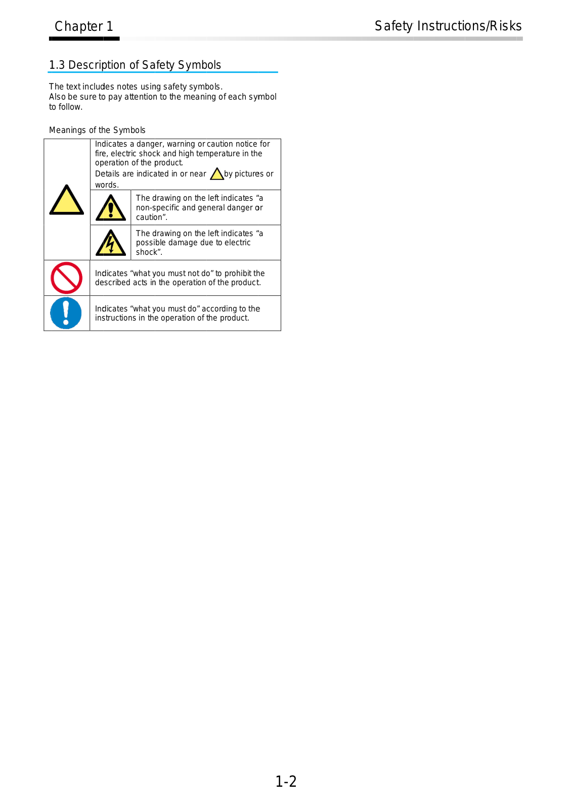
1.3 Descri ption of Safety Symbols


he text includ es notes usin g safety sym bols.


Also be sure t o pay attentio n to the meaning of each symbol


to follow.


Meanings of thhe Symbols

In dicates a danger, warning or caution notice for fir e, electric shoc k and high tem perature in the operation of the product.

De tails are indic ated in or near by picture s or wo rds.

The d rawing on the left indicates “a non-s pecific and general danger o r cauti on”.

The d rawing on the left indicates “a possible damage d e to electric shoc k”.

In dicates “what y ou must not d o” to prohibit th e de scribed acts in the operation of the product.

In dicates “what y ou must do” a ccording to the in structions in the operation of the product.

1-2

Chapter 1

Safety Instructions/Risks


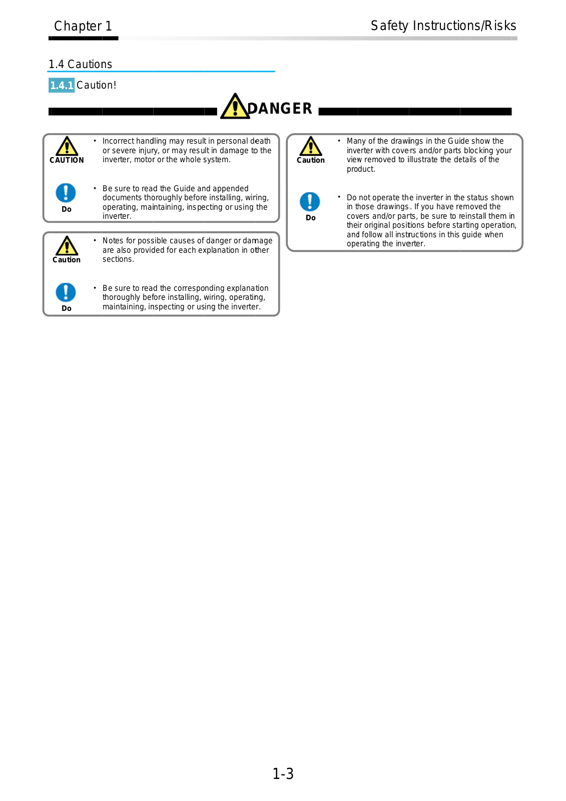
1.4 Cautio ns

1.4.1 Caution!

D ANGE R

1-3

Chapter 1

Safety Instructions/Risks


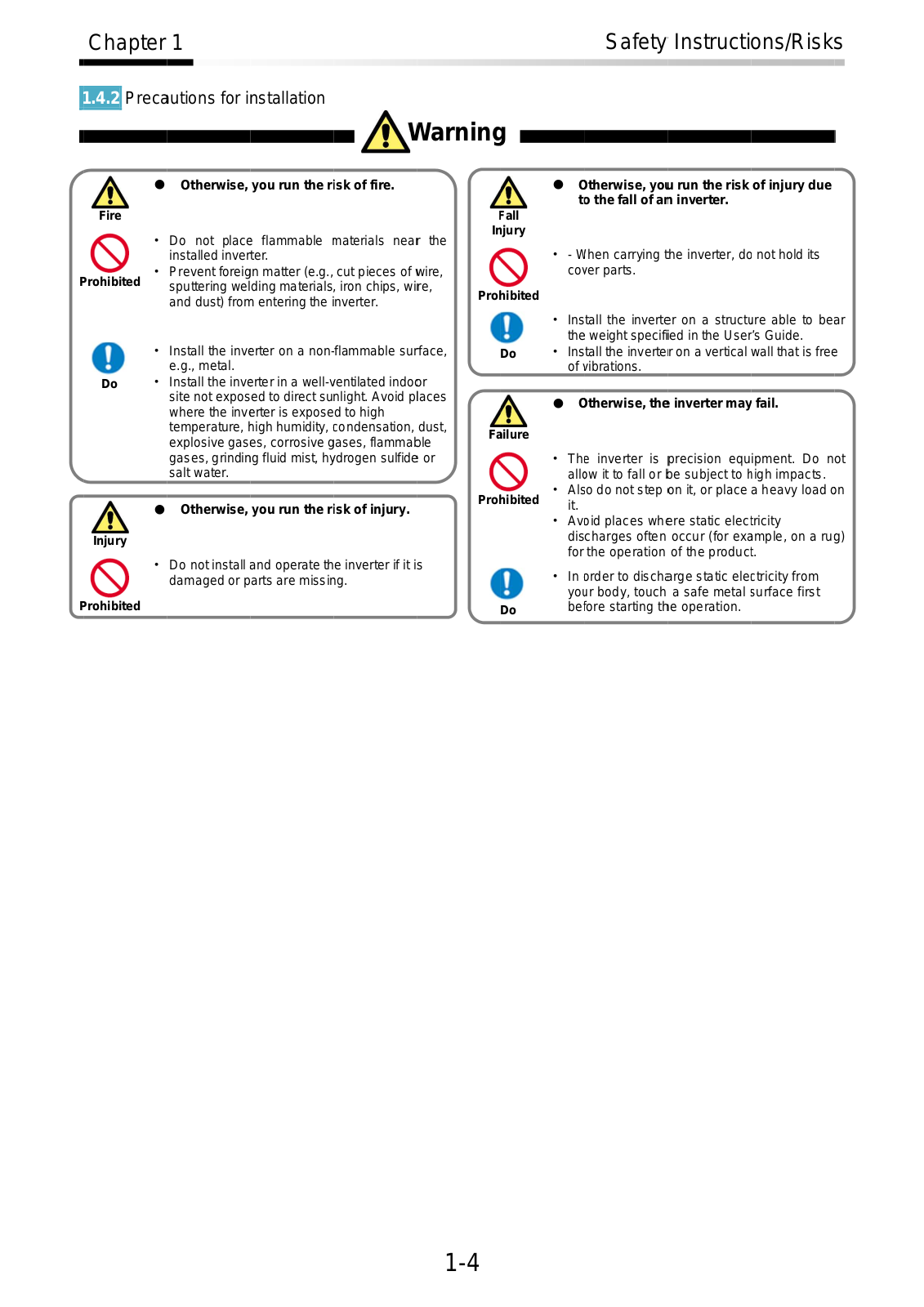
1.4.2 Preca utions for installation

Warning

1-4

Chapter 1

Safety Instructions/Risks


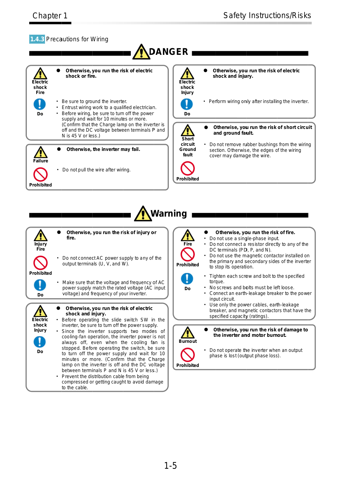
1.4.3 Preca utions for Wiring

D ANGE R

Warning

1-5

Chapter 1

Safety Instructions/Risks


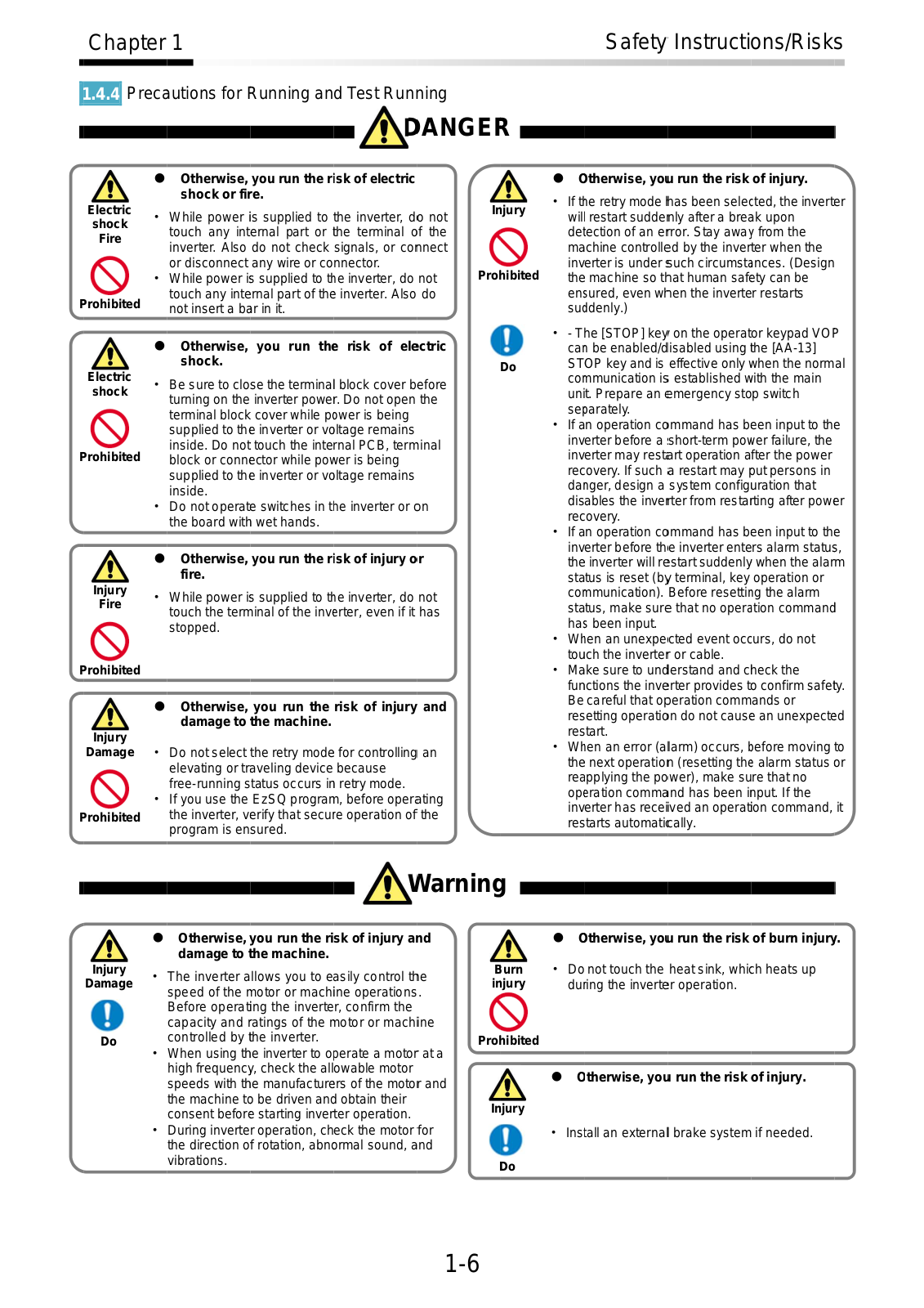
1.4.4 Preca utions for Running and Test Run ning

D ANGE R

Warning

1-6

Chapter 1

Safety Instructions/Risks


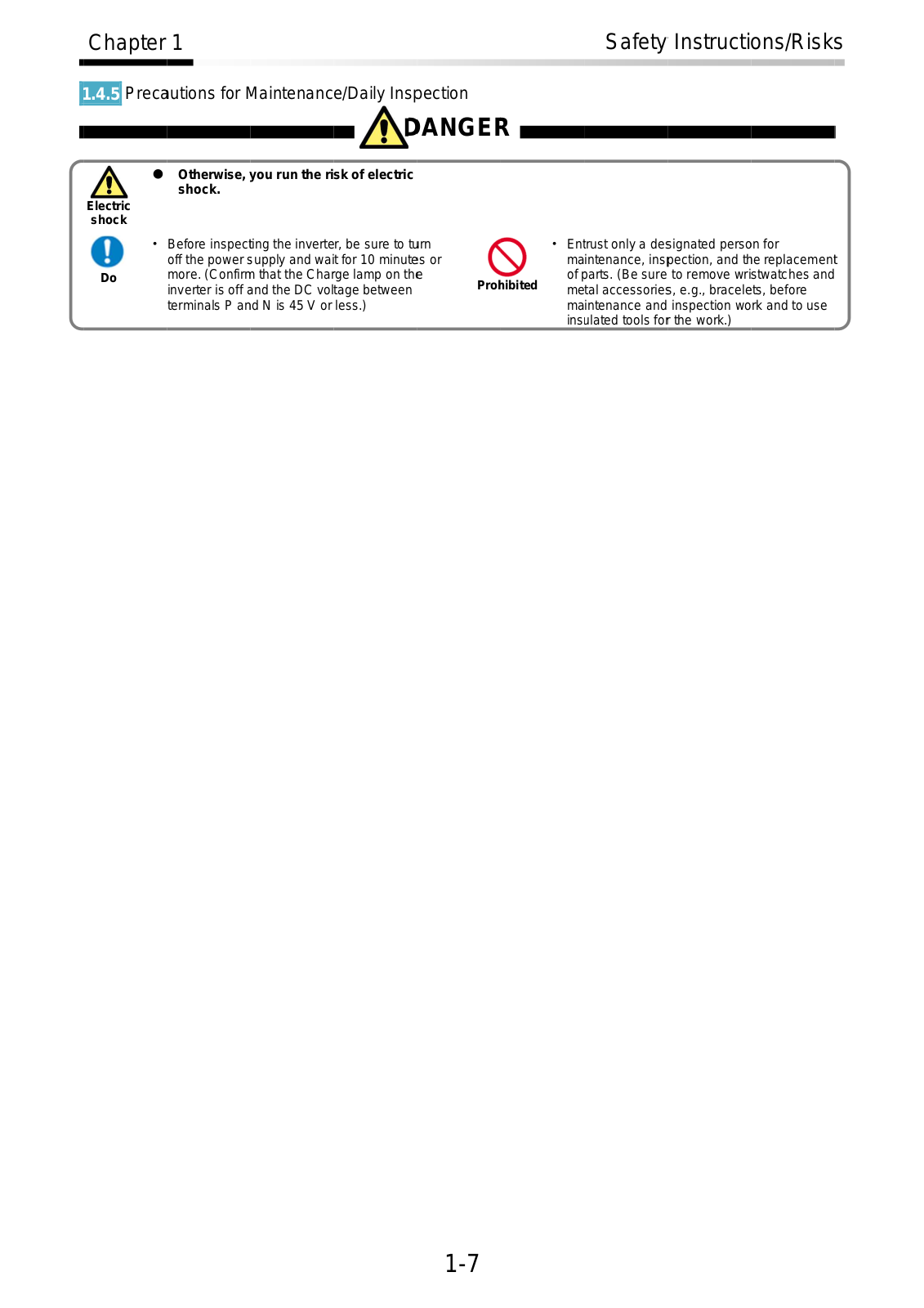
1.4.5 Preca utions for Maintenance/Daily Ins pection

D ANGE R

1-7

Chapter 1

Safety Instructions/Risks


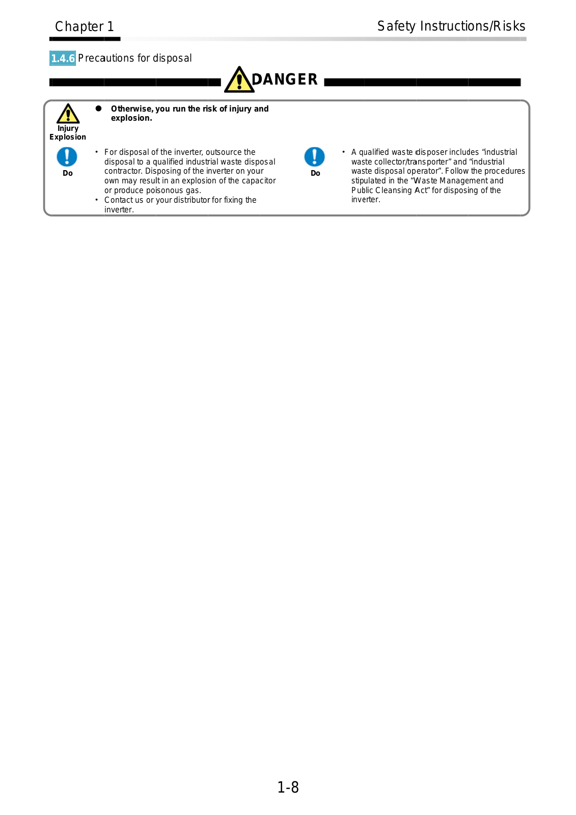
1.4.6 Preca utions for d isposal

D ANGE R

1-8

Chapter 1


Safety Instructions/Risks


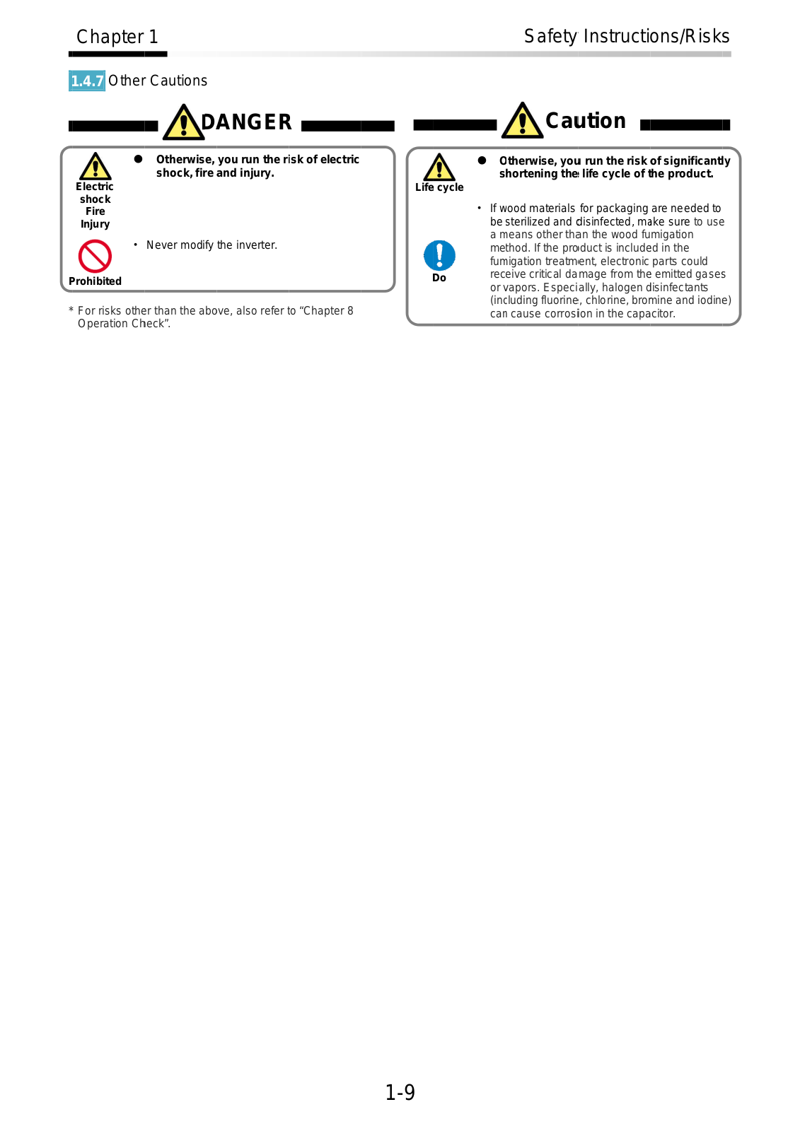
1.4.7

Other Cautions


DANGER


Ca ution


*For risks othe r than the above, also refer to “Chapter 8 Operation Ch eck”.

1-9


Chapter 1


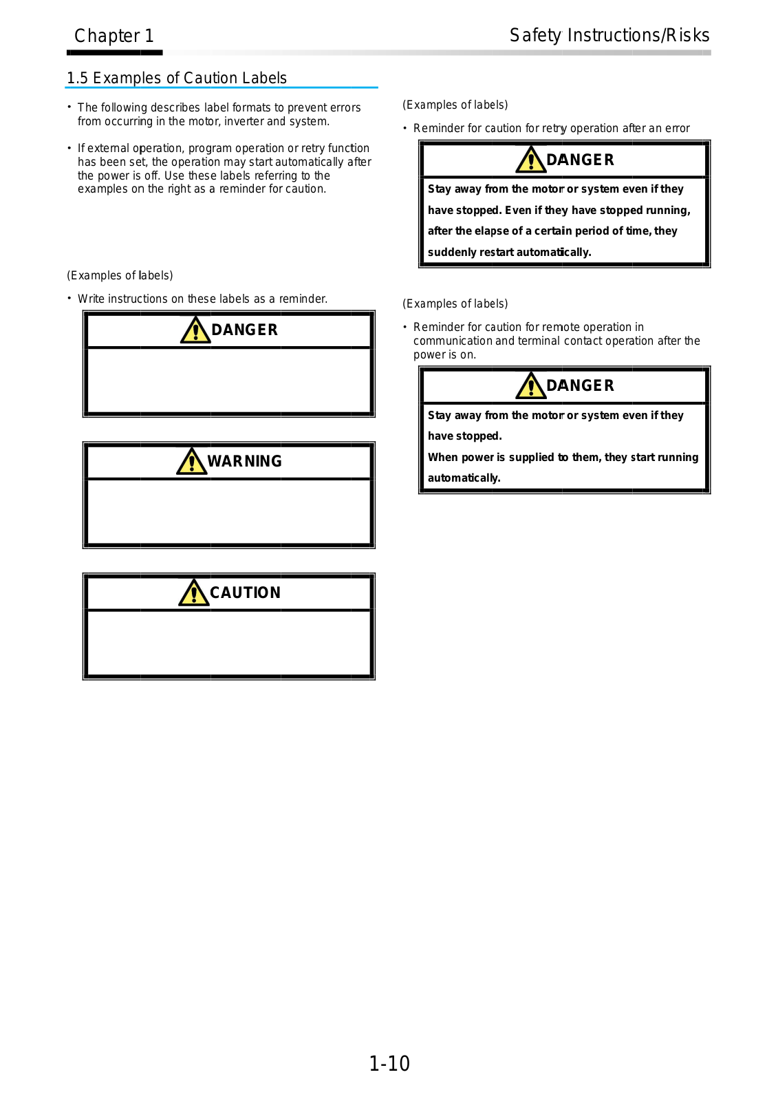
1.5 Examples of Caution Labels


The following describes la bel formats t prevent errors


from occurring in the mot or, inverter and system.


If external o peration, program operatio or retry function


has been se t, the operatio n may start automatically a fter


the power is off. Use these labels referring to the


examples o n the right as a reminder for caution.

(Examples of labels)

Write instruc tions on these labels as a r eminder.

DANGER

WARNING

Safety Instructions/Risks

(Ex amples of lab els)

Reminder for c aution for retr y operation after an error

D ANGER

Stay away from the motor or system ev en if they have stopped. Even if they have stopp ed running, after the ela pse of a certain period of time, they suddenly re start automatiically.

(Ex amples of lab els)

Reminder for c aution for rem ote operation in

c ommunication and terminal contact opera tion after the p ower is on.

D ANGER

Stay away from the motor or system ev en if they

have stopped.

When power is supplied to them, they start running

automatically.

CAUTION

1-10

Chapter 1

Safety Instructions/Risks


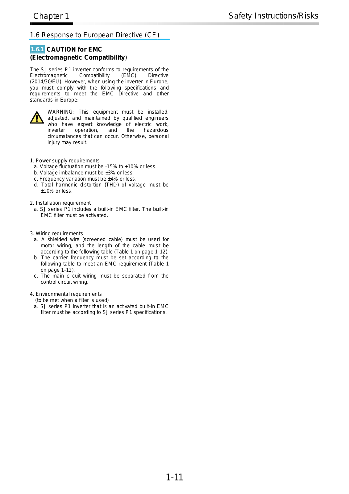
1.6 Respo nse to European Dir ective (CE)

1.6.1 CAUT ION for E MC

(Electromagnetic Co mpatibility)

he SJ series P1 inverter c onforms to re quirements of the Electromagne tic Comp atibility (EMC) Directive (2014/30/EU). However, when using the inverter in Eurrope,

y ou must co mply

with

the

following s pecifications

and

requirements to

meet

the

EMC Dir ective and

other

s tandards in E urope:


WARN ING: This e quipment must be instaalled, adjusteed, and main tained by q ualified engin eers who have expert knowledge of electric work, inverter operation, and the hazardous circumstances that can occur. Otherwise, pers onal injury may result.

1 . Power supp ly requiremen ts

a.Voltage fl uctuation must be -15% to +10% or less.

b.Voltage im balance must be ±3% or le ss.

c.Frequenc y variation must be ±4% or less.

d.Total harmonic distortion (THD) of voltage mus t be ±10% or less.

2 . Installation requirement

a. SJ series P1 includes a built-in EMC filter. The buuilt-in EMC filter must be acti vated.

3 . Wiring requirements

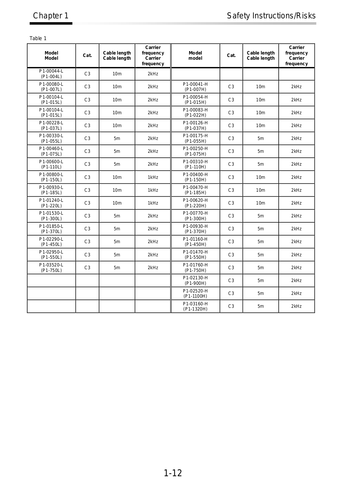
a.A shielde d wire (screened cable) must be use d for motor wir ing, and the length of th e cable mus t be according to the following table (Table 1 on page 1-12).

b.The carrier frequency must be set according to the following table to meet an EMC requirement (Ta ble 1

on page 1 -12).

c. The main circuit wirin g must be s parated from the control circuit wiring.

4 . Environmen tal requirements (to be met w hen a filter is used)

a.SJ series P1 inverter t hat is an activ ated built-in EMC filter must be according to SJ series P1 specificati ons.

1-11

Chapter 1

Safety Instructions/Risks


Table 1


Carrier

Model

Cat.

Cable length

frequency

Model

Cable length

Carrier


frequency


P1-00044-L

C3

10m

2kHz

(P1-004L)


P1-00080-L

C3

10m

2kHz

(P1-007L)


P1-00104-L

C3

10m

2kHz

(P1-015L)


P1-00104-L

C3

10m

2kHz

(P1-015L)


P1-00228-L

C3

10m

2kHz

(P1-037L)


P1-00330-L

C3

5m

2kHz

(P1-055L)


P1-00460-L

C3

5m

2kHz

(P1-075L)


P1-00600-L

C3

5m

2kHz

(P1-110L)


P1-00800-L

C3

10m

1kHz

(P1-150L)


P1-00930-L

C3

10m

1kHz

(P1-185L)


P1-01240-L

C3

10m

1kHz

(P1-220L)


P1-01530-L

C3

5m

2kHz

(P1-300L)


P1-01850-L

C3

5m

2kHz

(P1-370L)


P1-02290-L

C3

5m

2kHz

(P1-450L)


P1-02950-L

C3

5m

2kHz

(P1-550L)


P1-03520-L

C3

5m

2kHz

(P1-750L)


Carrier

Model

Cat.

Cable length

frequency

model

Cable length

Carrier


frequency


P1-00041-H

C3

10m

2kHz

(P1-007H)


P1-00054-H

C3

10m

2kHz

(P1-015H)


P1-00083-H

C3

10m

2kHz

(P1-022H)


P1-00126-H

C3

10m

2kHz

(P1-037H)


P1-00175-H

C3

5m

2kHz

(P1-055H)


P1-00250-H

C3

5m

2kHz

(P1-075H)


P1-00310-H

C3

5m

2kHz

(P1-110H)


P1-00400-H

C3

10m

2kHz

(P1-150H)


P1-00470-H

C3

10m

2kHz

(P1-185H)


P1-00620-H

C3

10m

2kHz

(P1-220H)


P1-00770-H

C3

5m

2kHz

(P1-300H)


P1-00930-H

C3

5m

2kHz

(P1-370H)


P1-01160-H

C3

5m

2kHz

(P1-450H)


P1-01470-H

C3

5m

2kHz

(P1-550H)


P1-01760-H

C3

5m

2kHz

(P1-750H)


P1-02130-H

C3

5m

2kHz

(P1-900H)


P1-02520-H

C3

5m

2kHz

(P1-1100H)


P1-03160-H

C3

5m

2kHz

(P1-1320H)


1-12

Chapter 1

Safety Instructions/Risks


1.6.2Caution for Machinery Directive (Functional Safety)

The SJ series inverter P1 will meet the requirements for functional safety.

Functional Safety Guide SJ-P1 will be provided for handling for functional safety. (In preparation)

1-13

Chapter 1

Safety Instructions/Risks


1.7 Response to UL standards

UL CAUTION

GENERAL:

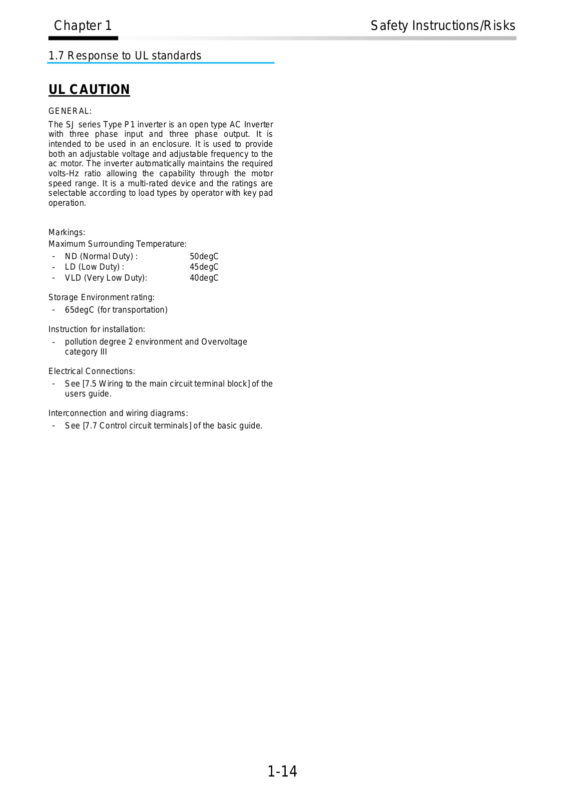
The SJ series Type P1 inverter is an open type AC Inverter with three phase input and three phase output. It is intended to be used in an enclosure. It is used to provide both an adjustable voltage and adjustable frequency to the ac motor. The inverter automatically maintains the required volts-Hz ratio allowing the capability through the motor speed range. It is a multi-rated device and the ratings are selectable according to load types by operator with key pad operation.

Markings:


Maximum Surrounding Temperature:


-

ND (Normal Duty) :

50degC

-

LD (Low Duty) :

45degC

- VLD (Very Low Duty):

40degC

Storage Environment rating:

-65degC (for transportation)

Instruction for installation:

-pollution degree 2 environment and Overvoltage category III

Electrical Connections:

-See [7.5 Wiring to the main circuit terminal block] of the users guide.

Interconnection and wiring diagrams:

-See [7.7 Control circuit terminals] of the basic guide.

1-14

Chapter 1

Safety Instructions/Risks


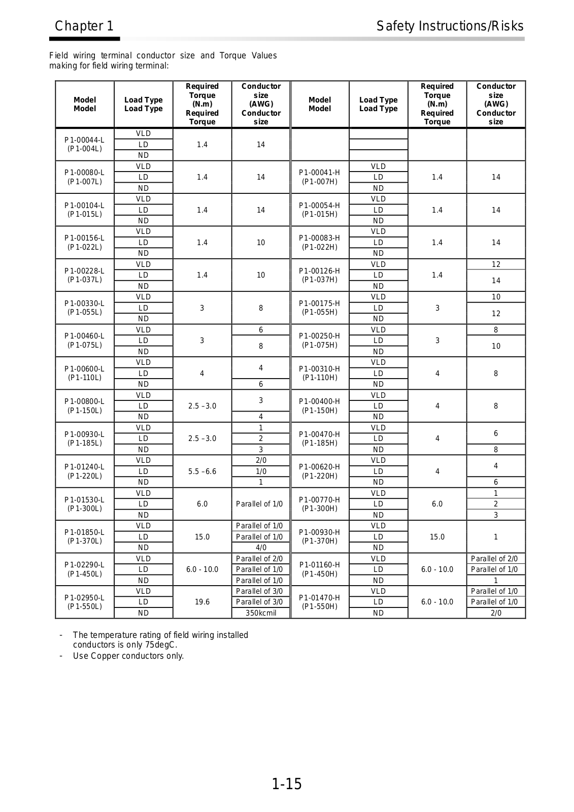
Field wiring terminal conductor size and Torque Values making for field wiring terminal:


Required

Conductor

Model

Load Type

Torque

size

(N.m)

(AWG)

Model

Load Type

Required

Conductor


Torque

size

P1-00044-L

VLD


LD

1.4

14

(P1-004L)

ND


P1-00080-L

VLD


LD

1.4

14

(P1-007L)

ND


P1-00104-L

VLD


LD

1.4

14

(P1-015L)

ND


P1-00156-L

VLD


LD

1.4

10

(P1-022L)

ND


P1-00228-L

VLD


LD

1.4

10

(P1-037L)

ND


P1-00330-L

VLD


LD

3

8

(P1-055L)

ND


P1-00460-L

VLD


6

LD

3


(P1-075L)

8

ND


P1-00600-L

VLD


4

LD

4

(P1-110L)


ND


6


P1-00800-L

VLD


3

LD

2.5 –3.0

(P1-150L)


ND


4


P1-00930-L

VLD


1

LD

2.5 –3.0

2

(P1-185L)

ND


3


P1-01240-L

VLD


2/0

LD

5.5 –6.6

1/0

(P1-220L)

ND


1


P1-01530-L

VLD


LD

6.0

Parallel of 1/0

(P1-300L)

ND


P1-01850-L

VLD


Parallel of 1/0

LD

15.0

Parallel of 1/0

(P1-370L)

ND


4/0


P1-02290-L

VLD


Parallel of 2/0

LD

6.0 - 10.0

Parallel of 1/0

(P1-450L)

ND


Parallel of 1/0


P1-02950-L

VLD


Parallel of 3/0

LD

19.6

Parallel of 3/0

(P1-550L)

ND


350kcmil


Required

Conductor

Model

Load Type

Torque

size

(N.m)

(AWG)

Model

Load Type

Required

Conductor


Torque

size

P1-00041-H

VLD


LD

1.4

14

(P1-007H)

ND


P1-00054-H

VLD


LD

1.4

14

(P1-015H)

ND


P1-00083-H

VLD


LD

1.4

14

(P1-022H)

ND


P1-00126-H

VLD


12

LD

1.4


(P1-037H)

14

ND


P1-00175-H

VLD


10

LD

3


(P1-055H)

12

ND


P1-00250-H

VLD


8

LD

3


(P1-075H)

10

ND


P1-00310-H

VLD


LD

4

8

(P1-110H)

ND


P1-00400-H

VLD


LD

4

8

(P1-150H)

ND


P1-00470-H

VLD


6

LD

4

(P1-185H)


ND


8


P1-00620-H

VLD


4

LD

4

(P1-220H)


ND


6


P1-00770-H

VLD


1

LD

6.0

2

(P1-300H)

ND


3


P1-00930-H

VLD


LD

15.0

1

(P1-370H)

ND


P1-01160-H

VLD


Parallel of 2/0

LD

6.0 - 10.0

Parallel of 1/0

(P1-450H)

ND


1


P1-01470-H

VLD


Parallel of 1/0

LD

6.0 - 10.0

Parallel of 1/0

(P1-550H)

ND


2/0


-The temperature rating of field wiring installed conductors is only 75degC.

-Use Copper conductors only.

1-15


Chapter 1


Safety Instructions/Risks


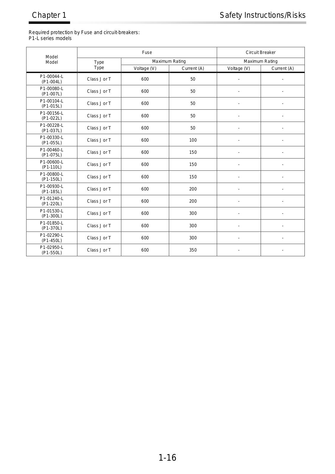
Required protection by Fuse and circuit-breakers:


P1-L series models


Model


Fuse


Circuit Breaker


Model

Type

Maximum Rating

Maximum Rating


Type

Voltage (V)

Current (A)

Voltage (V)

Current (A)


P1-00044-L

Class J or T

600

50

-

-


(P1-004L)


P1-00080-L

Class J or T

600

50

-

-


(P1-007L)


P1-00104-L

Class J or T

600

50

-

-


(P1-015L)


P1-00156-L

Class J or T

600

50

-

-


(P1-022L)


P1-00228-L

Class J or T

600

50

-

-


(P1-037L)


P1-00330-L

Class J or T

600

100

-

-


(P1-055L)


P1-00460-L

Class J or T

600

150

-

-


(P1-075L)


P1-00600-L

Class J or T

600

150

-

-


(P1-110L)


P1-00800-L

Class J or T

600

150

-

-


(P1-150L)


P1-00930-L

Class J or T

600

200

-

-


(P1-185L)


P1-01240-L

Class J or T

600

200

-

-


(P1-220L)


P1-01530-L

Class J or T

600

300

-

-


(P1-300L)


P1-01850-L

Class J or T

600

300

-

-


(P1-370L)


P1-02290-L

Class J or T

600

300

-

-


(P1-450L)


P1-02950-L

Class J or T

600

350

-

-


(P1-550L)


1-16


Chapter 1


Safety Instructions/Risks


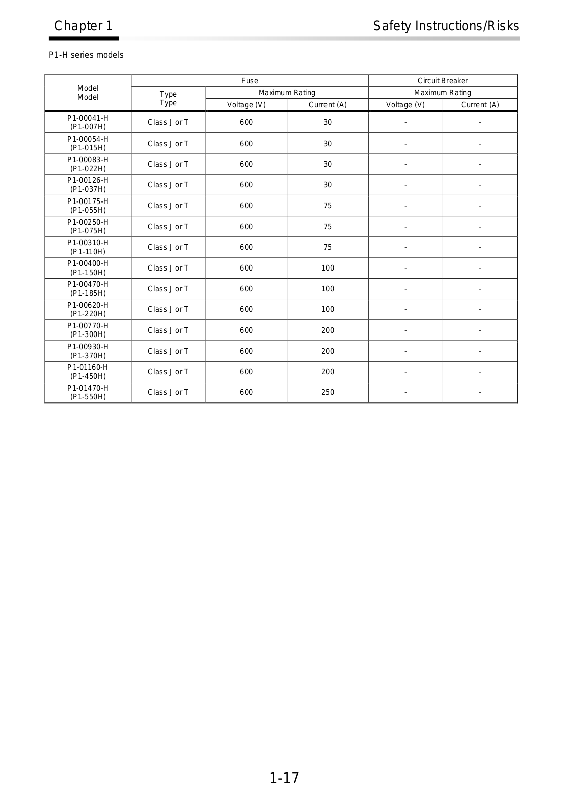
P1-H series models


Model


Fuse


Circuit Breaker


Type

Maximum Rating

Maximum Rating


Model


Type

Voltage (V)

Current (A)

Voltage (V)

Current (A)


P1-00041-H

Class J or T

600

30

-

-


(P1-007H)


P1-00054-H

Class J or T

600

30

-

-


(P1-015H)


P1-00083-H

Class J or T

600

30

-

-


(P1-022H)


P1-00126-H

Class J or T

600

30

-

-


(P1-037H)


P1-00175-H

Class J or T

600

75

-

-


(P1-055H)


P1-00250-H

Class J or T

600

75

-

-


(P1-075H)


P1-00310-H

Class J or T

600

75

-

-


(P1-110H)


P1-00400-H

Class J or T

600

100

-

-


(P1-150H)


P1-00470-H

Class J or T

600

100

-

-


(P1-185H)


P1-00620-H

Class J or T

600

100

-

-


(P1-220H)


P1-00770-H

Class J or T

600

200

-

-


(P1-300H)


P1-00930-H

Class J or T

600

200

-

-


(P1-370H)


P1-01160-H

Class J or T

600

200

-

-


(P1-450H)


P1-01470-H

Class J or T

600

250

-

-


(P1-550H)


1-17

Chapter 1

Safety Instructions/Risks


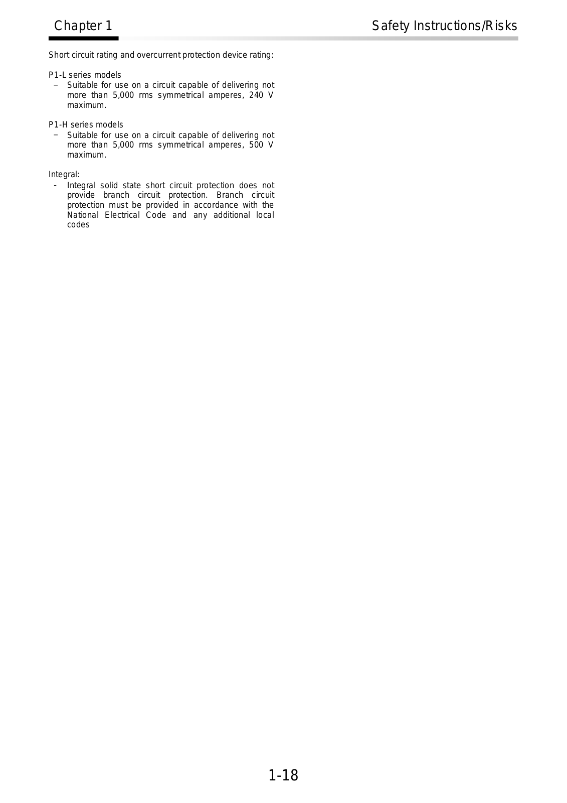
Short circuit rating and overcurrent protection device rating:

P1-L series models

-Suitable for use on a circuit capable of delivering not more than 5,000 rms symmetrical amperes, 240 V maximum.

P1-H series models

-Suitable for use on a circuit capable of delivering not more than 5,000 rms symmetrical amperes, 500 V maximum.

Integral:

-Integral solid state short circuit protection does not provide branch circuit protection. Branch circuit protection must be provided in accordance with the National Electrical Code and any additional local codes

1-18

Chapter 2

Handling of This User’s Guide


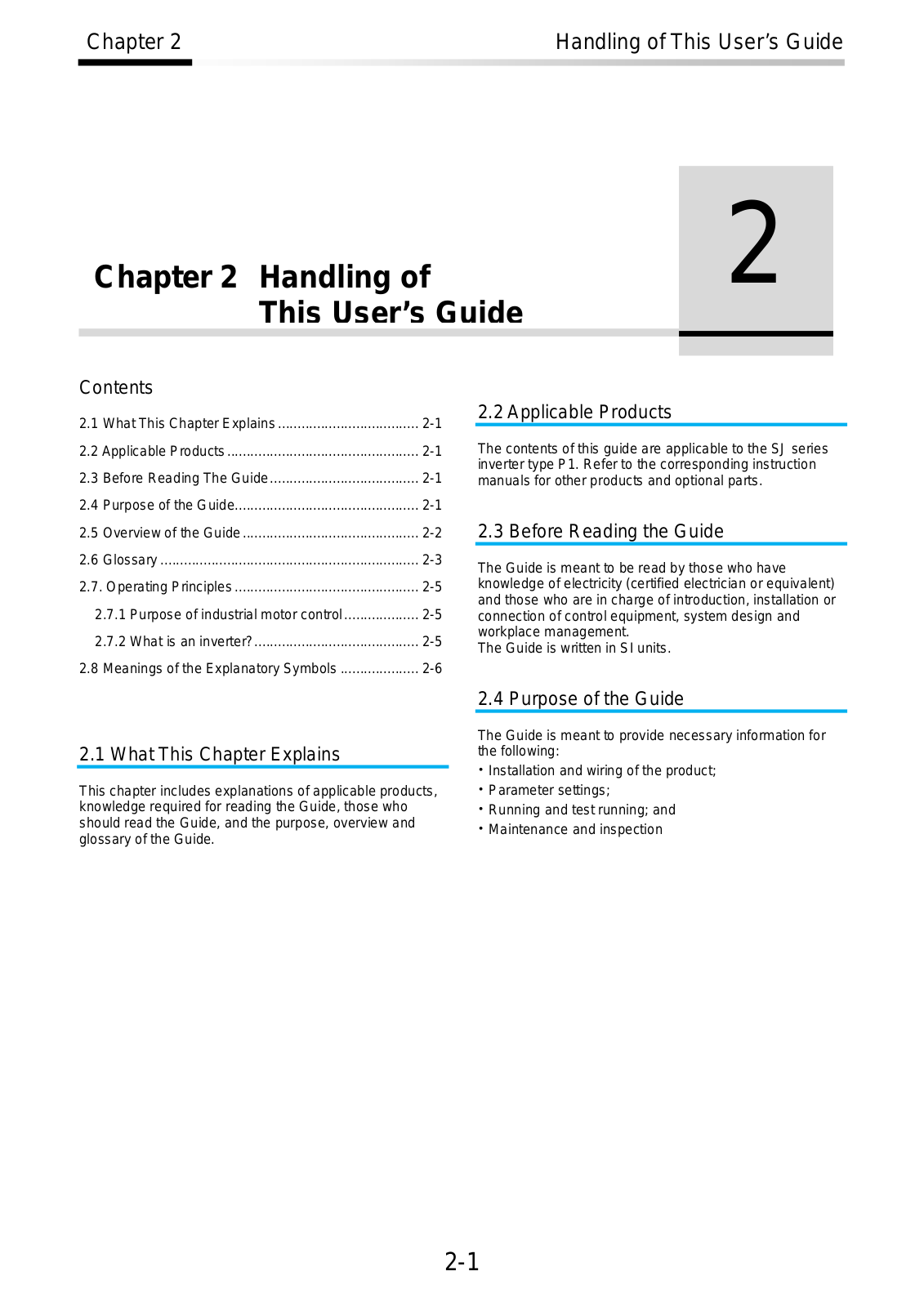
Chapter 2 Handling of

2

This User’s Guide


Contents

2.1

What This Chapter Explains ....................................

2-1

2.2 Applicable Products .................................................

2-1

2.3

Before Reading The Guide......................................

2-1

2.4

Purpose of the Guide...............................................

2-1

2.2 Applicable Products

The contents of this guide are applicable to the SJ series inverter type P1. Refer to the corresponding instruction manuals for other products and optional parts.

2.5

Overview of the Guide .............................................

2-2

2.6

Glossary ..................................................................

2-3

2.7. Operating Principles ...............................................

2-5

2.7.1 Purpose of industrial motor control ...................

2-5

2.7.2 What is an inverter?..........................................

2-5

2.8

Meanings of the Explanatory Symbols ....................

2-6

2.3 Before Reading the Guide

The Guide is meant to be read by those who have knowledge of electricity (certified electrician or equivalent) and those who are in charge of introduction, installation or connection of control equipment, system design and workplace management.

The Guide is written in SI units.

2.1 What This Chapter Explains

This chapter includes explanations of applicable products, knowledge required for reading the Guide, those who should read the Guide, and the purpose, overview and glossary of the Guide.

2.4 Purpose of the Guide

The Guide is meant to provide necessary information for the following:

Installation and wiring of the product;

Parameter settings;

Running and test running; and

Maintenance and inspection

2-1

Chapter 2

Handling of This User’s Guide


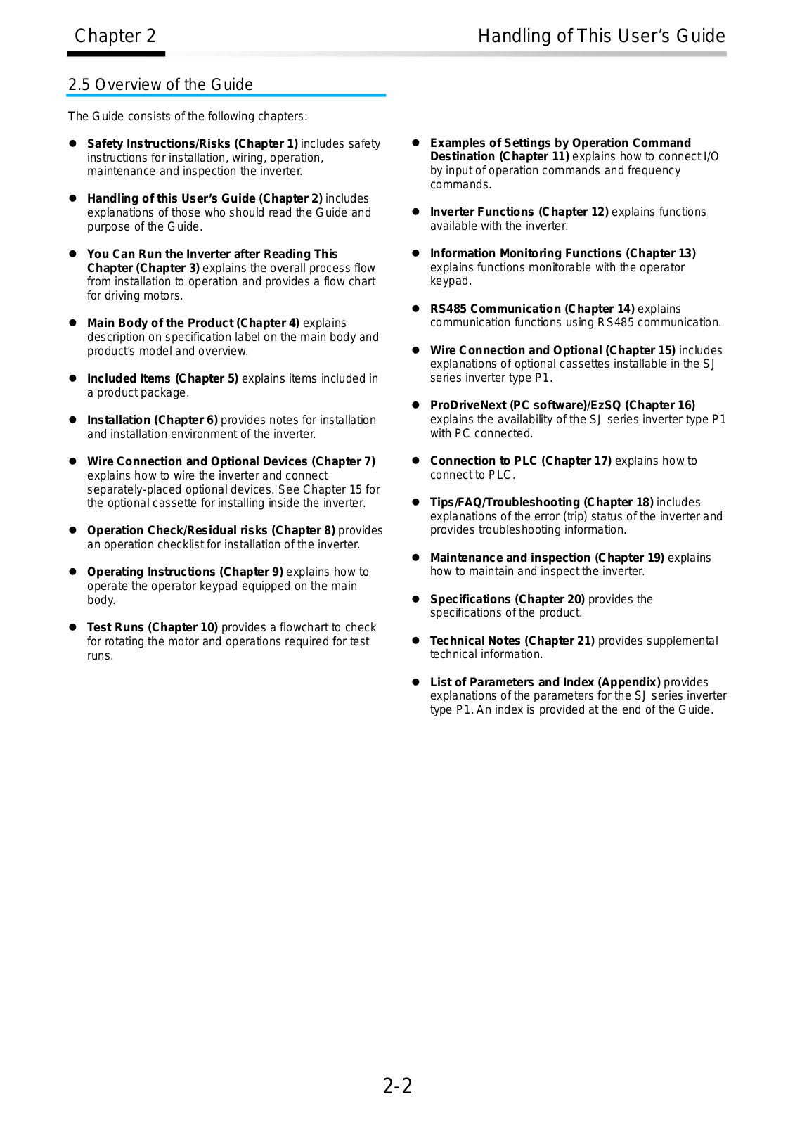
2.5 Overview of the Guide

The Guide consists of the following chapters:

Safety Instructions/Risks (Chapter 1) includes safety instructions for installation, wiring, operation, maintenance and inspection the inverter.

Handling of this User’s Guide (Chapter 2) includes explanations of those who should read the Guide and purpose of the Guide.

You Can Run the Inverter after Reading This Chapter (Chapter 3) explains the overall process flow from installation to operation and provides a flow chart for driving motors.

Main Body of the Product (Chapter 4) explains description on specification label on the main body and product’s model and overview.

Included Items (Chapter 5) explains items included in a product package.

Installation (Chapter 6) provides notes for installation and installation environment of the inverter.

Wire Connection and Optional Devices (Chapter 7) explains how to wire the inverter and connect separately-placed optional devices. See Chapter 15 for the optional cassette for installing inside the inverter.

Operation Check/Residual risks (Chapter 8) provides an operation checklist for installation of the inverter.

Operating Instructions (Chapter 9) explains how to operate the operator keypad equipped on the main body.

Test Runs (Chapter 10) provides a flowchart to check for rotating the motor and operations required for test runs.

Examples of Settings by Operation Command Destination (Chapter 11) explains how to connect I/O by input of operation commands and frequency commands.

Inverter Functions (Chapter 12) explains functions available with the inverter.

Information Monitoring Functions (Chapter 13) explains functions monitorable with the operator keypad.

RS485 Communication (Chapter 14) explains communication functions using RS485 communication.

Wire Connection and Optional (Chapter 15) includes explanations of optional cassettes installable in the SJ series inverter type P1.

ProDriveNext (PC software)/EzSQ (Chapter 16) explains the availability of the SJ series inverter type P1 with PC connected.

Connection to PLC (Chapter 17) explains how to connect to PLC.

Tips/FAQ/Troubleshooting (Chapter 18) includes explanations of the error (trip) status of the inverter and provides troubleshooting information.

Maintenance and inspection (Chapter 19) explains how to maintain and inspect the inverter.

Specifications (Chapter 20) provides the specifications of the product.

Technical Notes (Chapter 21) provides supplemental technical information.

List of Parameters and Index (Appendix) provides explanations of the parameters for the SJ series inverter type P1. An index is provided at the end of the Guide.

2-2

Chapter 2

Handling of This User’s Guide


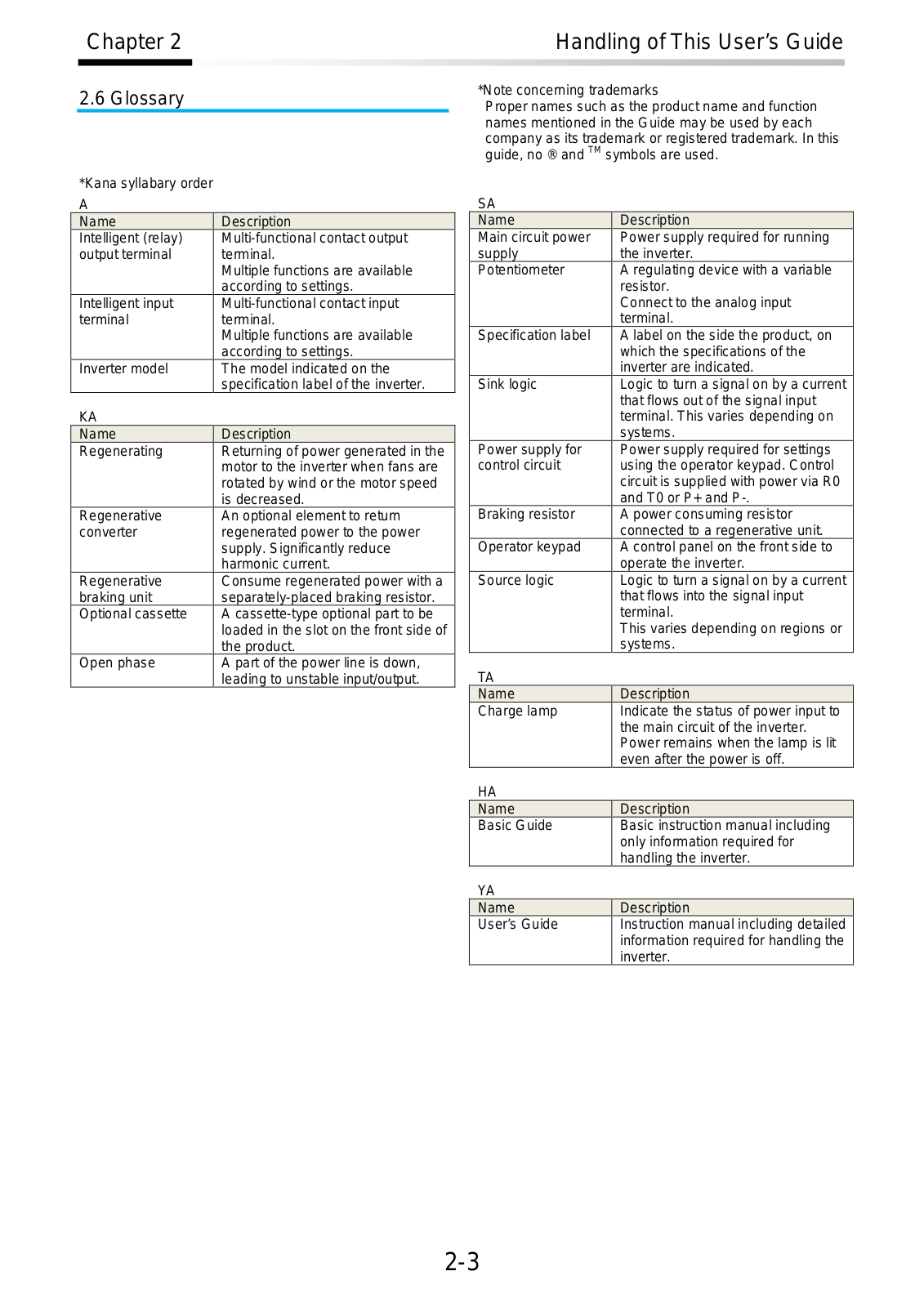
2.6 Glossary

*Kana syllabary order A

Name

Description

Intelligent (relay)

Multi-functional contact output

output terminal

terminal.


Multiple functions are available


according to settings.

Intelligent input

Multi-functional contact input

terminal

terminal.


Multiple functions are available


according to settings.

Inverter model

The model indicated on the


specification label of the inverter.

KA


Name

Description

Regenerating

Returning of power generated in the


motor to the inverter when fans are


rotated by wind or the motor speed


is decreased.

Regenerative

An optional element to return

converter

regenerated power to the power


supply. Significantly reduce


harmonic current.

Regenerative

Consume regenerated power with a

braking unit

separately-placed braking resistor.

Optional cassette

A cassette-type optional part to be


loaded in the slot on the front side of


the product.

Open phase

A part of the power line is down,


leading to unstable input/output.

*Note concerning trademarks

Proper names such as the product name and function names mentioned in the Guide may be used by each company as its trademark or registered trademark. In this guide, no ® andTM symbols are used.

SA

Name

Description

Main circuit power

Power supply required for running

supply

the inverter.

Potentiometer

A regulating device with a variable


resistor.


Connect to the analog input


terminal.

Specification label

A label on the side the product, on


which the specifications of the


inverter are indicated.

Sink logic

Logic to turn a signal on by a current


that flows out of the signal input


terminal. This varies depending on


systems.

Power supply for

Power supply required for settings

control circuit

using the operator keypad. Control


circuit is supplied with power via R0


and T0 or P+ and P-.

Braking resistor

A power consuming resistor


connected to a regenerative unit.

Operator keypad

A control panel on the front side to


operate the inverter.

Source logic

Logic to turn a signal on by a current


that flows into the signal input


terminal.


This varies depending on regions or


systems.

TA


Name

Description

Charge lamp

Indicate the status of power input to


the main circuit of the inverter.


Power remains when the lamp is lit


even after the power is off.

HA


Name

Description

Basic Guide

Basic instruction manual including


only information required for


handling the inverter.

YA


Name

Description

User’s Guide

Instruction manual including detailed


information required for handling the


inverter.

2-3

Chapter 2

Handling of This User’s Guide


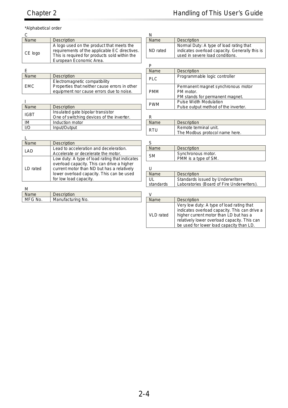
*Alphabetical order C

Name

Description


A logo used on the product that meets the

CE logo

requirements of the applicable EC directives.

This is required for products sold within the


European Economic Area.

E


Name

Description


Electromagnetic compatibility

EMC

Properties that neither cause errors in other


equipment nor cause errors due to noise.

I


Name

Description

IGBT

Insulated gate bipolar transistor

One of switching devices of the inverter.


IM

Induction motor

I/O

Input/Output

L


Name

Description

LAD

Lead to acceleration and deceleration.

Accelerate or decelerate the motor.


Low duty: A type of load rating that indicates


overload capacity. This can drive a higher

LD rated

current motor than ND but has a relatively


lower overload capacity. This can be used


for low load capacity.

M


Name

Description

MFG No.

Manufacturing No.

N

Name

Description


Normal Duty: A type of load rating that

ND rated

indicates overload capacity. Generally this is


used in severe load conditions.

P


Name

Description

PLC

Programmable logic controller


Permanent magnet synchronous motor

PMM

PM motor.


PM stands for permanent magnet.

PWM

Pulse Width Modulation

Pulse output method of the inverter.


R


Name

Description

RTU

Remote terminal unit.

The Modbus protocol name here.


S


Name

Description

SM

Synchronous motor.

PMM is a type of SM.


U


Name

Description

UL

Standards issued by Underwriters

standards

Laboratories (Board of Fire Underwriters).

V


Name

Description


Very low duty: A type of load rating that


indicates overload capacity. This can drive a

VLD rated

higher current motor than LD but has a


relatively lower overload capacity. This can


be used for lower load capacity than LD.

2-4

Chapter 2

2.7. Operating Principles

A

This section describes operating principles briefly.

2.7.1Purpose of industrial motor control

A Hitachi inverter can vary three phase motor speed. Varying speed can provide advantages in many applications.

For example, it is useful for the purposes on the right.

2.7.2What is an inverter?

Handling of This User’s Guide

Energy savings

Ex.) HVAC (air-conditioner); fans; pumps

Adjacent processes requiring speed adjustment Ex.) textile machines; printing machines

Load requiring torque

Ex.) machine tools; processing machines; transportation equipment

Load requiring fine control

Ex.) elevators; food processing; medical devices

An inverter can control the rotation speed and power consumption of motors by changing the frequency and voltage input to motors.

Motors waste energy running fans and pumps using a commercial power supply and controlling the flow rate using valves and dumpers. An inverter can lower the commercial power supply frequency and voltage, which contributes to energy savings by powering down without valves and dampers.

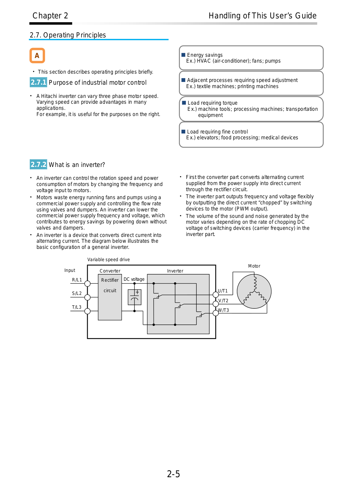
An inverter is a device that converts direct current into alternating current. The diagram below illustrates the basic configuration of a general inverter.

Variable speed drive

First the converter part converts alternating current supplied from the power supply into direct current through the rectifier circuit.

The inverter part outputs frequency and voltage flexibly by outputting the direct current “chopped” by switching devices to the motor (PWM output).

The volume of the sound and noise generated by the motor varies depending on the rate of chopping DC voltage of switching devices (carrier frequency) in the inverter part.

Input


Motor

Converter

Inverter

R/L1

Rectifier

DC voltage

S/L2

circuit

U/T1


V/T2

T/L3


W/T3


2-5

Chapter 2

Handling of This User’s Guide


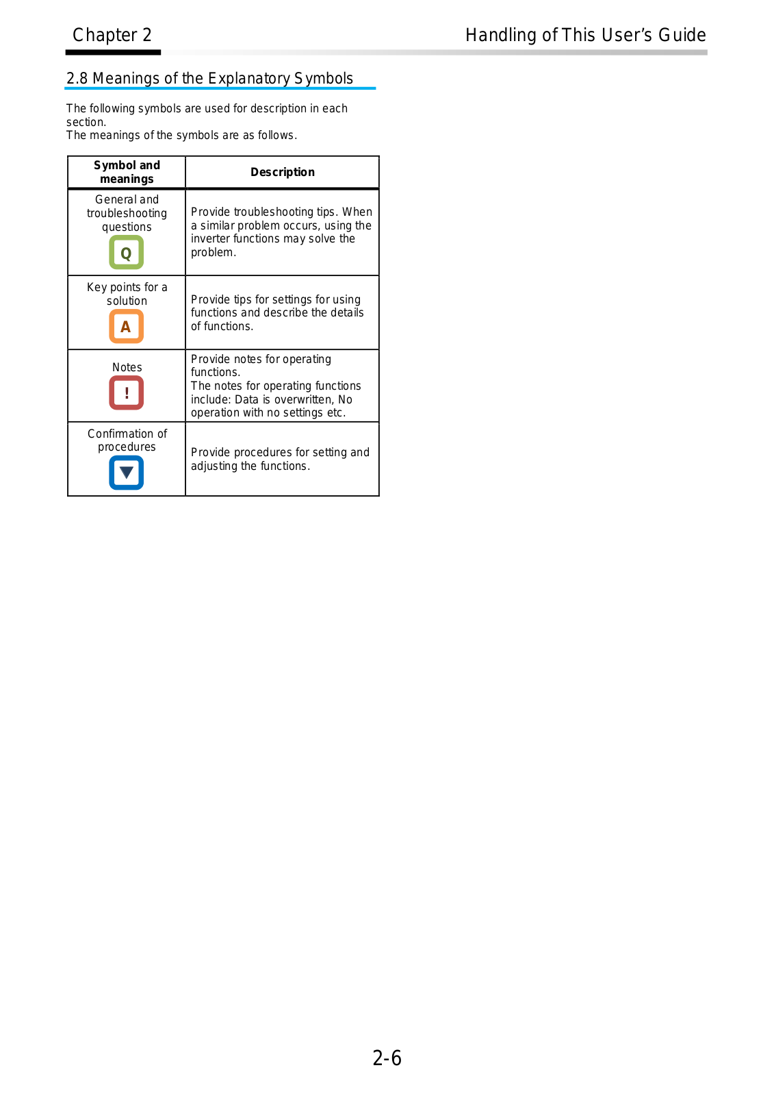
2.8 Meanings of the Explanatory Symbols

The following symbols are used for description in each section.

The meanings of the symbols are as follows.

Symbol and

Description

meanings


General and

Provide troubleshooting tips. When

troubleshooting

questions

a similar problem occurs, using the

Q

inverter functions may solve the

problem.


Key points for a

Provide tips for settings for using

solution

A

functions and describe the details

of functions.


Notes

Provide notes for operating

functions.


!

The notes for operating functions

include: Data is overwritten, No


operation with no settings etc.


Confirmation of


procedures

Provide procedures for setting and


adjusting the functions.


2-6

Chapter 3

You Can Run the Inverter after Reading This Chapter


Chapter 3 You Can Run the Inverter

3


after Reading This Chapter


Contents

3.1

What This Chapter Explains .....................................

3-1

3.2

Flow for Preparation of Operation ............................

3-2

3.2.1 Check the Inverter .............................................

3-2

3.2.2 Install the Inverter ..............................................

3-2

3.2.3 Wire the Inverter to Check the Power Supply....

3-3

3.2.4 Operate the Operator Keypad ...........................

3-3

3.2.5 Prepare for Rotating the Motor ..........................

3-4

3.2.6 Troubleshooting .................................................

3-4

3.1 What This Chapter Explains

This chapter provides an operational process (flow) to do a test run.

For installation, wiring and settings for operation and detailed information of inverter functions, see the corresponding sections. Make sure to carefully read “Chapter 1 Safety Instructions/Risks” and corresponding sections for safety work.

3-1

Chapter 3

You Can Run the Inverter after Rea ding This Chapter


3.2 Flow fo r Prepara tion of Op eration

3.2.1 Ch eck the In verter

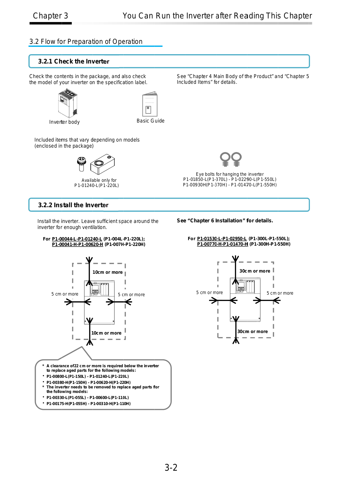
Check the con tents in the p ackage, and a lso check the model of your inverter on the specific ation label.

See “Chapter 4 M ain Body of t he Product” a nd “Chapt er 5 Included Items” fo r details.

Invert

er body


Basic G

uide


Included ite ms that vary d epending on models (enclosed in the package )

Avail able only for

P1-0124 0-L(P1-220L)

3.2.2 Ins tall the Inv erter

Install the inverter. Leave sufficient space around th e inverter for enough ventilation.

For P1-00044-L-P1-01240-L (P1-004L-P1-220L);

P1-00041-H-P1-006 20-H (P1-007H -P1-220H)

Eye bolts for hanging the inverter

P 1-01850-L(P1-370L) - P1-022 90-L(P1-550L) P 1-00930H(P1-3 70H) - P1-014 70-L(P1-550H)

See “Chapter 6 I nstallation” f or details.

For P1-01530-L-P1-02950-L (P1-300L-P1-5 50L);

P1-00770-H-P1-01470-H (P1-300H-P1-550H)


30c

m or more


10cm or more


5 cm or more


5 cm

or more

5 cm

or more


5 c

m or more


30cmm

or more

1

0cm or more


*A cleara nce of22 cm or more is required below the invert er to repla ce aged parts fo r the following models:

P1-00800-L(P1-150L) - P 1-01240-L(P1-22 0L)

P1-00380-H(P1-150H) - P1-00620-H(P1-220H)

*The inve rter needs to be removed to replace aged parts f or the following models:

P1-00330-L(P1-055L) - P 1-00600-L(P1-11 0L)

P1-00175-H(P1-055H) - P1-00310-H(P1-110H)

3-2

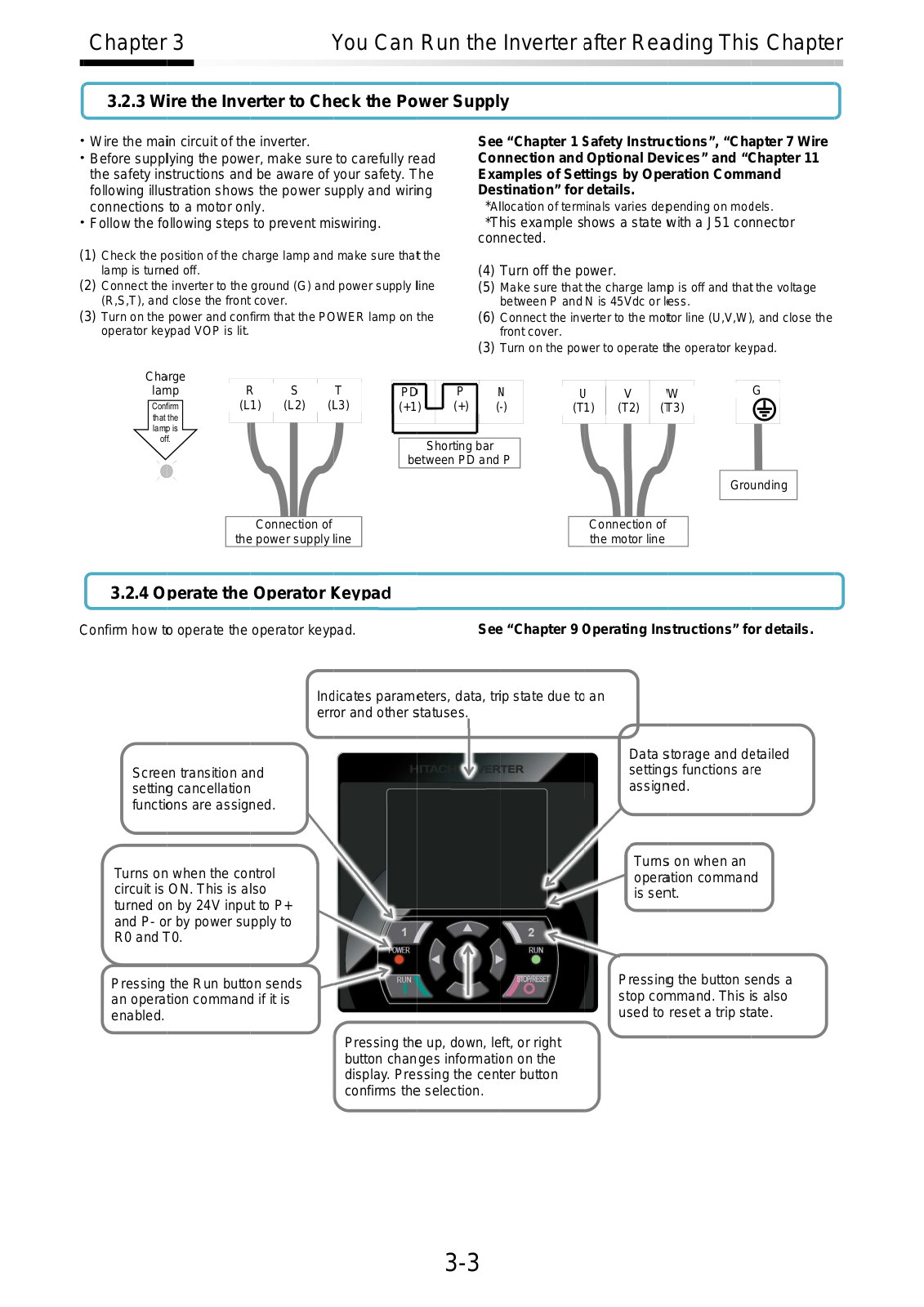
Make sure that the charge lamp is off and that the voltage between P and N is 45Vdc or l ess.
Connect the inverter to the mo tor line (U,V,W), and close the front cover.
Turn on the po wer to operate t he operator key pad.

Chapter 3 You Can Run the Inverter after Rea ding This Chapter

3.2.3 Wire the Inv erter to Check the Power Supply

Wire the main circuit of th e inverter.

Before supplying the pow er, make sure to carefully re ad the safety instructions and be aware of your safety. The following illustration show s the power s upply and wiring connections to a motor only.

Follow the fo llowing steps to prevent miswiring.

(1)Check the position of the c harge lamp and make sure tha t the lamp is turn ed off.

(2)Connect the inverter to the ground (G) and power supply line (R,S,T), and close the front cover.

(3)Turn on the power and confirm that the PO WER lamp on the operator ke ypad VOP is lit.

See “Chapter 1 S afety Instrucctions”, “Chap ter 7 Wir e Co nection and Optional De vices” and “C hapter 11 Exa mples of Settings by Ope ration Comm and

Des tination” for details.

*Allocation of terminals varies de pending on mo els.

*T his example shows a state with a J51 co nnector connected.

(4) Turn off the power.

(5)

(6)

(3)

Cha rge


la mp


S


T

PD


P


N

U

V


W

G

Con firm

(L1)

(L2)

(

L3)

(+1)


(+)


(

-)

(T1)

(T2)

(

T3)


that the


lam p is


off.


Shorting bar


b etween PD and P


Grounding


Connection of


Connection of


the power supply ine


the motor line


3.2.4 Operate the Operator Keypad

Confirm how t o operate the operator keyp ad. See “Chapter 9 perating Ins tructions” for details.

Scree n transition a nd settin g cancellation functi ons are assig ned.

Turns on when the co ntrol circuit is ON. This is also turned o n by 24V input to P+ and P- or by power supply to R0 and T0.

Ind icates param eters, data, trip state due to an error and other s tatuses.

Data s torage and d etailed setting s functions are assign ed.

Turns on when an opera tion command is sennt.

Pressing the Run butto n sends an operation comman d if it is enabled.

Pressing th e up, down, left, or right button changes informati on on the display. Pressing the center button confirms the selection.

Pressin g the button sends a stop co mmand. This is also used to reset a trip state.

3-3

Chapter 3

You Can Run the Inverter after Rea ding This Chapter


3.2.5 Prepare for R otating the Motor


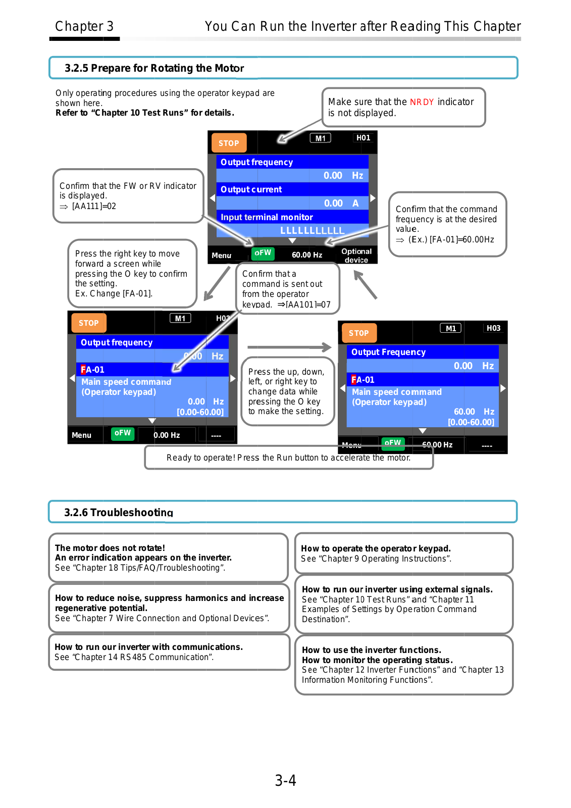
Only operating procedure s using the operator keypad are


Make s

ure that the

NRDY indicat

or


shown here.


Refer to “Ch apter 10 Test Runs” for details.

is not

displayed.


H01

STOP

Confirm tha t the FW or RV indicator is displayed .

[AA111] =02

Output frequency

0.00 H

Output c urrent

0.00 A

minal monitor

LLLLL

Press t he right key to move

FW

60.00 Hz

forward a screen while


pressing the O key to confirm

Confirm that a

the setting.

command is sent out

Ex. Ch ange [FA-01].

from the operator


key pad. [AA101]=07

Conffirm that the command freq uency is at th desired valu e.

( Ex.) [FA-01]= 60.00Hz

STOP

H03

M1

ST OP

Outp ut frequency

Ou tput Freque ncy


0.

00

Hz


FA-01


Pr

ess the up, do

wn,


Main

speed comm

and


left, or right key

to


FA

-01


(Oper

ator keypad)


change data while


M in speed co mmand


0.00

Hz


pr essing the O k ey


(Operator keyp ad)


[0.00-6

0.00]


to make the setting.


60

.00

Hz


[0.0

0-60.00]

Menu

oFW

0.00 Hz

----


oFW

00 Hz

----

Ready to o perate! Press the Run button to acceler te the motor.

3.2.6 Tr oubleshooting

The motor d oes not rotate!

An error ind ication appears on the inverter.

See “Chapter 18 Tips/FAQ /Troubleshooting”.

How to redu ce noise, suppress harmonics and in crease regenerativ e potential.

See “Chapter 7 Wire Conn ection and O ptional Device s”.

How to run our inverter with commun ications.

See “Chapter 14 RS485 Communicatio ”.

H ow to operate the operator keypad.

Se e “Chapter 9 Operating Instructions”.

H ow to run ou r inverter usi ng external s ignals.

S ee “Chapter 1 0 Test Runs” and “Chapter 11 E xamples of Settings by Operation Comm and D estination”.

H ow to use the inverter functions.

H ow to monitor the operati ng status.

S ee “Chapter 1 2 Inverter Fun ctions” and “C hapter 13 Information Mo nitoring Functiions”.

3-4

Chapter 4

Main Body of the Product


4

Chapter 4 Main Body of the Product

Contents

4.1

What This Chapter Explains ....................................

4-1

4.2

External Appearance of the Product ........................

4-2

4.3

Model of the Product and Specification Label .........

4-3

4.3.1 Model of the Product ........................................

4-3

4.3.2 Specification Label.........................................

4-3

4.3.3 Indication for Japan ..........................................

4-4

4.4

Method of Inquiry and Product Warranty .................

4-5

4.4.1 Method of Inquiry about Product.......................

4-5

4.4.2 Product Warranty and Inquiry ...........................

4-5

4.4.3 Limitation of Liability .........................................

4-6

4.4.4 How to use our Warranty Service .....................

4-6

4.4.5 Changes in Product Specification.....................

4-6

4.4.6 Notes for Applying the Product .........................

4-6

4.4.7 Supplement ......................................................

4-6

4.1 What This Chapter Explains

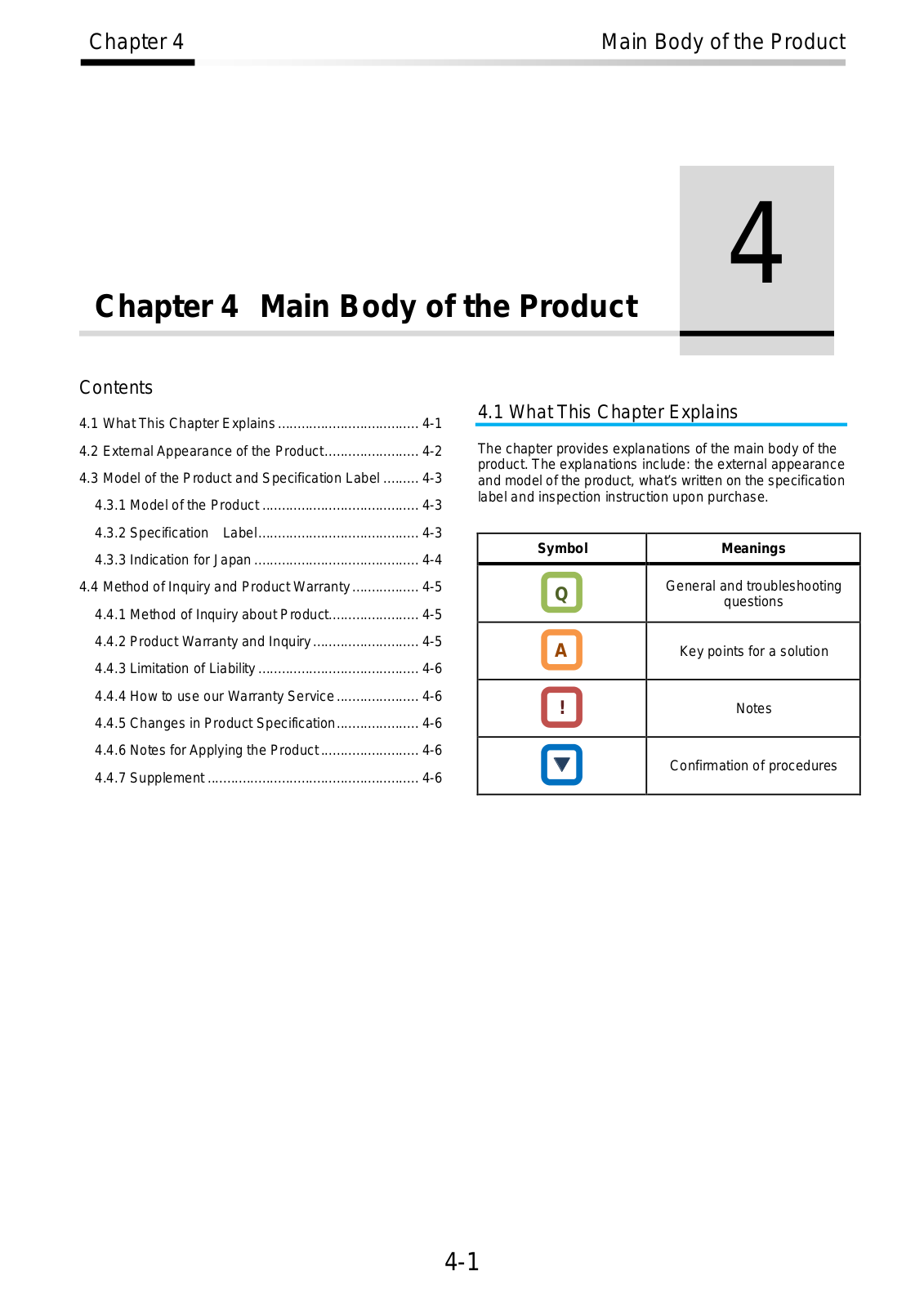
The chapter provides explanations of the main body of the product. The explanations include: the external appearance and model of the product, what’s written on the specification label and inspection instruction upon purchase.

Symbol

Meanings


Q

General and troubleshooting

questions


A

Key points for a solution


!

Notes


Confirmation of procedures


4-1

Loading...
+ 717 hidden pages