

Page 1

Hitachi Inverter
SJ300/L300P SERIES
SJ-LW
INSTRUCTION MANUAL
Thank you for purchase of “HITACHI INVERTER”. This manual
explains about treatment of “SJ-LW (LonWorks Option)”. By reading this
manual and an instruction manual of inverter use practically for
installation, maintenance, and inspection. After reading this manual,
keep it handy for future reference.
Make sure to reach this manual to the end user.
(LonWorks Option)
Table of Contents
Chapter1 Introduction 1
Chapter2 Installation method of printed board 5
Chapter3 Wiring, Connecting 6
Chapter4 Setting 7
Chapter5 LonWorks Communication Function 8
Chapter6 Control from LonWorks 17
Chapter7 Countermeasure for abnormality 21
Appendix1 Parameter Object Lists
Appendix2 Trip monitor data address
After reading this manual, keep it at handy for future reference.
23
32
NB623X
Page 2

SAFTY PRECAUTIONS
- Request Thank you for purchase of “SJ-LW (LonWorks Option)”.
This instruction manual explains about treatment and maintenance of “SJ-LW ”. Before using the product,
carefully read this manual with the instruction manual of inverter, and keeps it handy for quick reference of
operator and maintenance inspector. Before installing, operating, maintenance and inspection read this
manual carefully and follow the instructions exactly.
Always keep various kinds of specification mentioned in this manual and use exactly. And make sure to
prevent trouble by correct inspection and maintenance. Make sure to reach this manual to the end user.
- About treatment of this manual (1)Please consent that mentioned items of this manual may be change without permission.
(2)Keep this manual carefully not to lose because it can not be reissued
(3)All right reserved.
(4)Contents in this manual is written to make assurance doubly sure but, but please contact if you have
some doubts about spelling mistakes, omitted word etc.
(5)Please agree that there is no responsibility for effects resulted, in spite of contents above mentioned.
- About trademark (1) Echelon, Neuron, LON, LonTalk, LonWorks, 3120 are registered trademark of Echelon Corporation.
(LON: Local Operating Network)
(2) LonMaker, LonMark are trademark of Echelon Corporation.
- Reference
W hen Co nne ct ing S J- LW to LON netwo rk ,XI F f ile is n eces s ar y as ex ter na l in ter fac e file .
XIF file is possible to download from the web site below.
http://www.hitachi-ds.com
General information regarding LonWorks and how to get LonW orks specificatio ns , re fer to the web site belo w.
http://www.lonmark.org
Revision His tor y Table
No.
1. Initial release of Manual NB623X Sep. 2001 NB623X
Revision contents The date of issued Manual No.
Except this table, revised only spelling mistakes omitted words, and error writings without notice.
Page 3
SAFTY PRECAUTIONS
!
!
!
!
SAFTY PRECAUTIONS
Carefully read this manual and all of the warning labels attached to the inverter before installing, operating,
maintaining, inspecting, it. Safety precautions are classified into “Warning” and “Caution” in this manual.
:Indicates a potentially hazardous situation which, if not avoided, can result in serious
WARNING
injury or death.
CAUTION
:Indicates a potentially hazardous situation which, if not avoided, can result in minor to
moderate injury, or serous damage to the product
The situation described in may, if not avoided, lead to serious results. Important safety
measures are described in CAUTION (as well as WARNING) so be sure observe them.
Notes are described in this manual in “(Note)”. Carefully read the contents and follow them exactly.
CAUTION
CAUTION
In all the illustrations in this manual, covers and safely device are occasionally removed to describe the
details. When the product is operated, make sure that the covers and safety devices are placed as they
were specified originally and operate it according to the instruction manual.
Page 4

SAFTY PRECAUTIONS
!
!
WARNING
Wiring:
W iring work shall be carried out by electrical experts.
Otherwise, there is a danger of electric shock, fire and/or damage of product.
Implement wiring after checking that the power supply is off.
Otherwise, there is a danger of electric shock and/or fire.
Operating:
Be sure not to touch the surface or the terminal of option board while energizing.
Otherwise, there is a danger of electric shock and/or fire.
Be sure not to remove the LonWorks option printed board while operating.
Otherwise, there is a danger of electric shock and/or fire.
Maintenance, Inspection and Part Replacement:
Wait at least 10 minutes after turning off the input power supply before performing maintenance and
inspection.
(Confirm the charge lamp on the inverter is off, checks direct current voltage between P-N terminals and
confirm it is less than 45V)
Otherwise, there is a danger of electric shock.
Make sure that only qualified persons will perform maintenance, inspection, and part replacement
(Before st ar tin g th e work , rem ov e me tall ic o bje cts fr om your per son (wr is twa tch , br ac ele t, etc .) .
Be sure to use tools protected with insulation.)
Otherwise, there is a danger of electric shock and/or injury.
Note:
Never modify the unit.
Otherwise, there is a da nger o f e lec tric sh ock and /o r inju r y.
CAUTION
Installation:
Be sure not to let the foreign matter enter such as wire clippings, spatter from welding, metal shaving,
dust etc.
Otherwise, there is a danger of fire.
Be sure to fix inverter to option printed board with an attached fixed screw.
Otherwise, there is a danger of connecting error.
Be sure to fasten the screws connecting signal wire in side of option printed board. Check for any
loosening of screw.
Otherwise, there is a danger of connecting error.
Wiring:
Be sure to fasten the screws not to loose.
Otherwise, there is a danger of connecting error.
Operation:
Check rotary direction, abnormal motor noise and vibrations during operating.
Otherwise, there is a da nger o f inju r y to pe rso nnel and/o r ma chi ne brea kage
Page 5

CHAPTER 1 INTRODUCTION
1.1 INSPECTION UPON UNPACKING
Make sure to treat the product carefully not to give shock and vibration while unpacking. Check that the
product is the one you ordered, no defect, and that there is no damage during transportation.
(Content s of pack i ng)
(1) SJ-LW (LonWorks option printed board):1 (also Install Manual atached)
(2) Instruction manual:1
(3) Screws fixed printed board (M3 times 8 mm):2
If you discover any problems, contact your sales agent immediately.
1.2 INQUIRY OF THE PRODUCT AND WARRANTY FOR THE PRODUCT
1.2.1 REQUIRE WHILE INQUIRING
If inquiry of breakage, question, damage etc. is needed, please tell the following information to the supplier
you ordered or the nearest Hitachi Distributor.
(1) Type(SJ-LW )
(2) Manuf ac tu rin g num b er (It em of lab e l, th at labe le d s urfac e of pr i nte d bo ard . SJ -LW XXX
(3) Date of purchasing
(4) Contents of inquiry
Damage parts and its condition etc.
・
Question parts and their contents etc.
・
In order to shorten impossible working time, standing spare unit is recommended.
)
1.2.2 WARRANTY OF THE PRODUCT
This product is guaranteed to last for one year after purchase. But, the next case is toll repair, even if within
warranty period.
(1) In case caused by operating mistake, and incorrect repair and modification.
(2) Trouble caused by reasons except the shipped product.
(3) In case of using in range over the value of specification.
(4) In case caused by natural calamity, disaster, and secondary disaster.
Warranty mentioned here means warranty for shipped product itself. Damage caused by trouble of shipped
product is not guaranteed.
[Replacement]
Any inspection and replacement after the expiration of warranty period (one-year) shall be charged to the
purchaser. And also any inspection and repair which are not covered in warranty mentioned above, even if it
is within warranty period, it shall be charged to the purchaser. If you require the replacement, please contact
your Hitachi distributor.
1
Page 6
CHAPTER 1 INTRODUCTION
1.3 Outline of product
SJ-LW is LonWorks communication board for SJ300/L300P series inverter.
SJ300/L300P series inverter can get to connect another devices via LonWorks when install SJ-LW.
SJ-LW is possible to connect for all models of SJ300/L300P series.
The SJ-LW option card communi cate s a ccording to t he L on Works P roto col Stan dard ANS I/EIA 709. 1- A -1999.
This means that it can communicate with all LonWorks nodes that comply with this standard, but it does not
necessarily mean that all services available in the LonWorks standard are supported. The “LonMark
Functional Profile: Variable Speed motor Drive” (doc no. 6010_11) is supported.
In a control system the option board will act as a node that can be read and written to, from any other
LonWorks node that has SNVT’s that corresponds to the one on SJ-LW.
(Note) RS485 communication function is disabled by installing SJ-LW to the inverter.
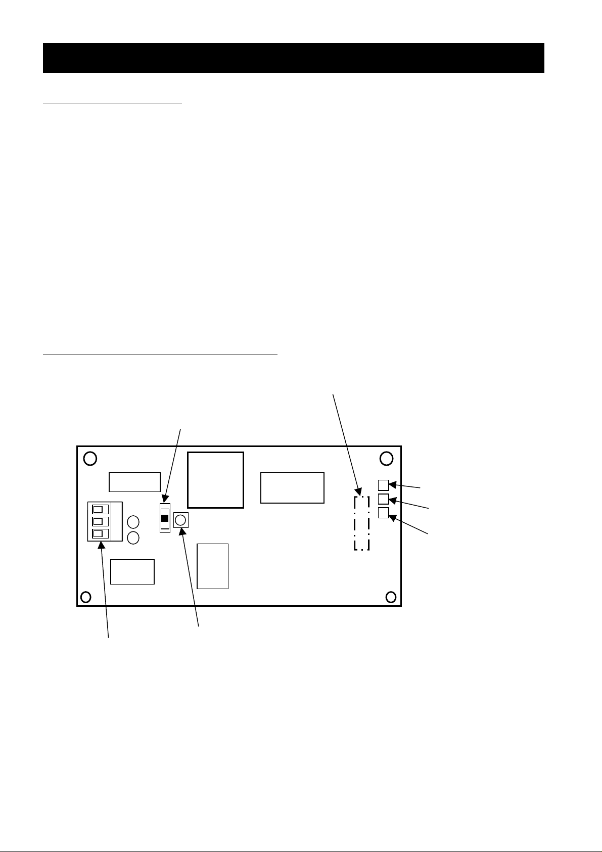
1.4 Appearance and Names of Parts
Figure 1-1 indicates the appearance of SJ-LW.
Connector for connection to SJ 300 /L300 P(Rea r o f unit)
Terminal S witch(S2 )
BUS
NO
FT
Service Pin (S1)
LonWorks contact (open type)
PhoenixContactCo.Ltd.(MC1.5/3‑ST‑3.81)etc
Serial Channel Status LE D (S ER IAL )
LonWorks Service LED (SERV)
Power/Status LED ( POWER)
Figure 1-1 Appearance of SJ-LW
2
Page 7
CHAPTER 1 INTRODUCTION
118KT1234510001
118KT1234510001118KT1234510001
118KT1234510001
0101
1.5 LonWorks Supported Version
SJ-LW can use following Manufacturing number (MFG No) of SJ300/L300P series.
After Manufacturing number : XX8KXXXXXXXXXXXX(SJ300-0.4-55kW / L300P-11-75kW supported
XXEMXXXXXXXXXXXX(SJ300-75-132kW / L300P-90-132kW supported
)
)
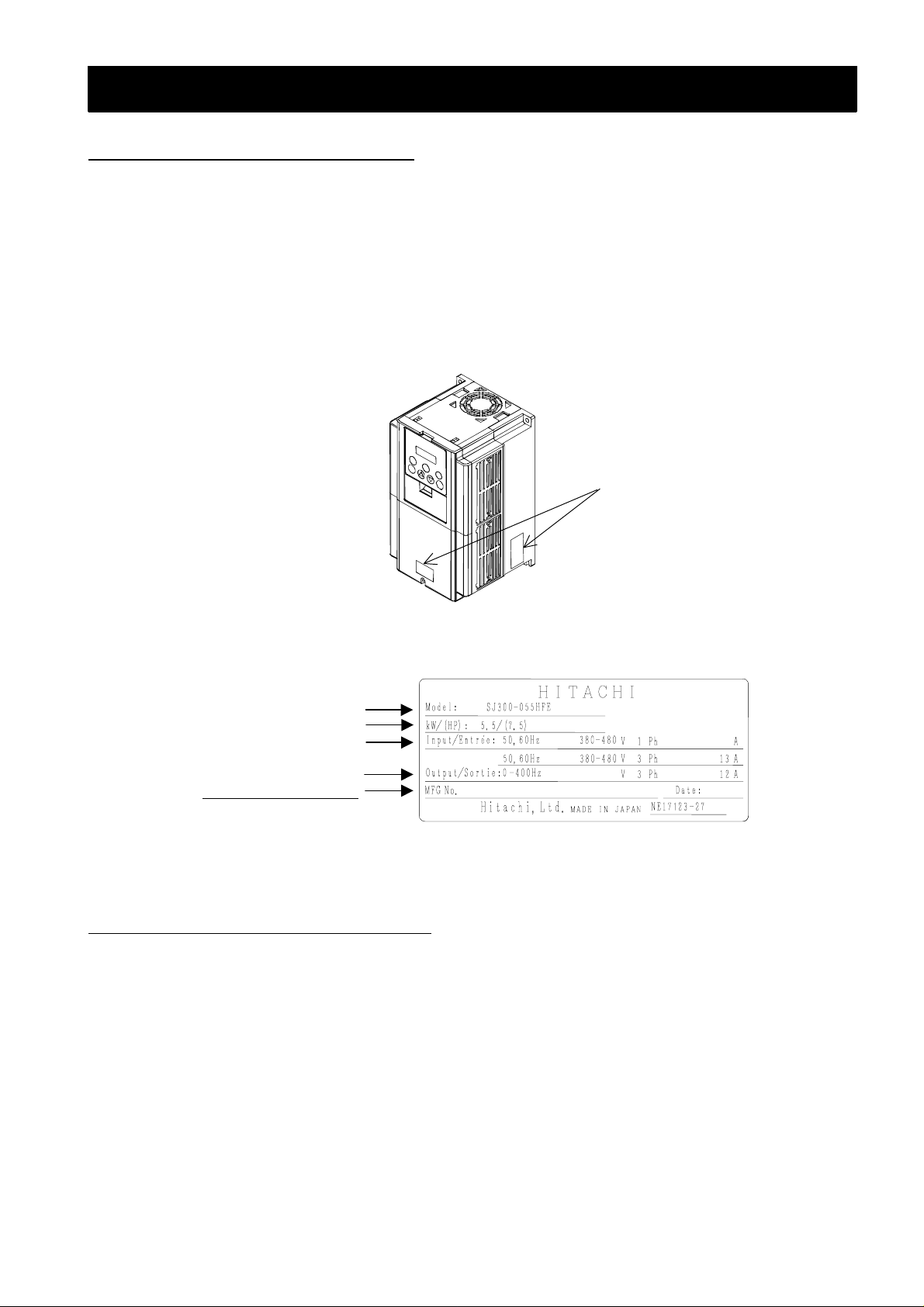
(Note) Manufacturing number is written in specifications label on main body of SJ300/L300Pseries. Refer to
figure 1- 2, f igur e 1- 3.
(Figure 1-2 , 1- 3 ar e t he example of SJ 3 00 se r ies . L3 00P ser i es ar e th e s am e manne r as SJ 300 ser ies .)
Specifications label
Figure 1-2 Position of specifications label
Inverter model
Maximum applicable motor
Input ratings
Output ratings
Manufacturing numbe r
Figure 1- 3 Co nt ent s of spe cif i cat ion s l abe l
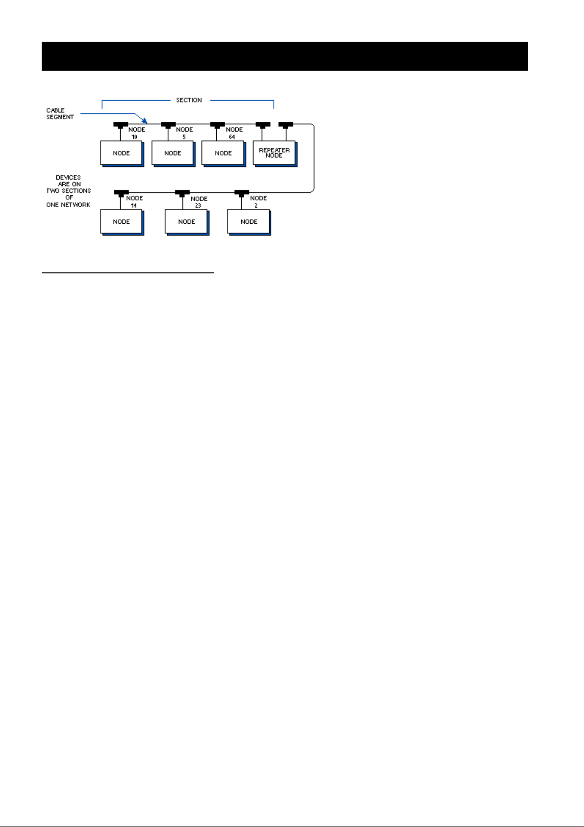
1.6 Technical features of Lonworks
Transmission Technique:
- Free topology (FTT-10A) twisted pair cable
- Transmission rate 78kbits/s
Max Bus length: Bus up to 2000 m
Max. node-to-node distance: 500m
Max amount of nodes: 32.385 nodes divided as 127 nodes/subnet, 255 subnets/domain.
Medium Ac c ess : Pr edi ct ive CS MA
Data types: Peer-to-peer communication
LonWorks communication ASIC: TMPN3120FE5 chip from Toshiba.
LonWorks transceiver: FTT10A from Echelon.
3
Page 8
CHAPTER 1 INTRODUCTION
1.7 Production specification
Bacicaly, the environmental specification of the SJ-LW is in accordance with SJ300/L300P series inverter.
Please refer the instruction manual of SJ300/L300P series.
But only application temperature of SJ-LW is different. Please note.
applicat i on temperature : 0 t o 50 deg re e
4
Page 9
CHAPTER 2 INSTALLATION METHOD OF PRINTED BOARD
p
g
p
(
)
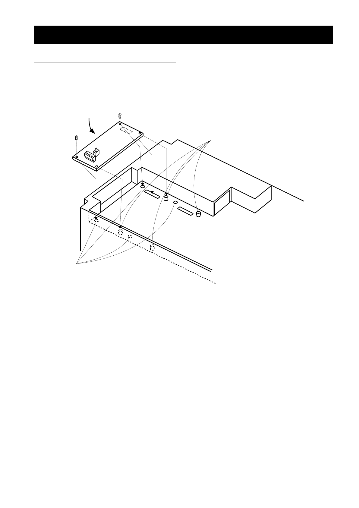
2.1 Mounting method of option board
Figure 2-1 describes how to mount the option board to the option port 1 or 2.
There are four holes on th e optio n boa rd, mat ch the t wo o f th em with t he screw holes on t he o ption po rt 1 or 2 .
and mount the other two holes with the guide posts which are located on the option port 1 and 2. To avoid
connection failure, secure the option board with screws after connection.
Option board
Guide posts for mountin
the option board.
Option port 1
Screw holes for secure o
M3 Screws
O
tion port 2
tion board.
Figure 2-1 In st al l ation o f opt io n bo a rd
5
Page 10
CHAPTER 3 WIREING,CONNECTING
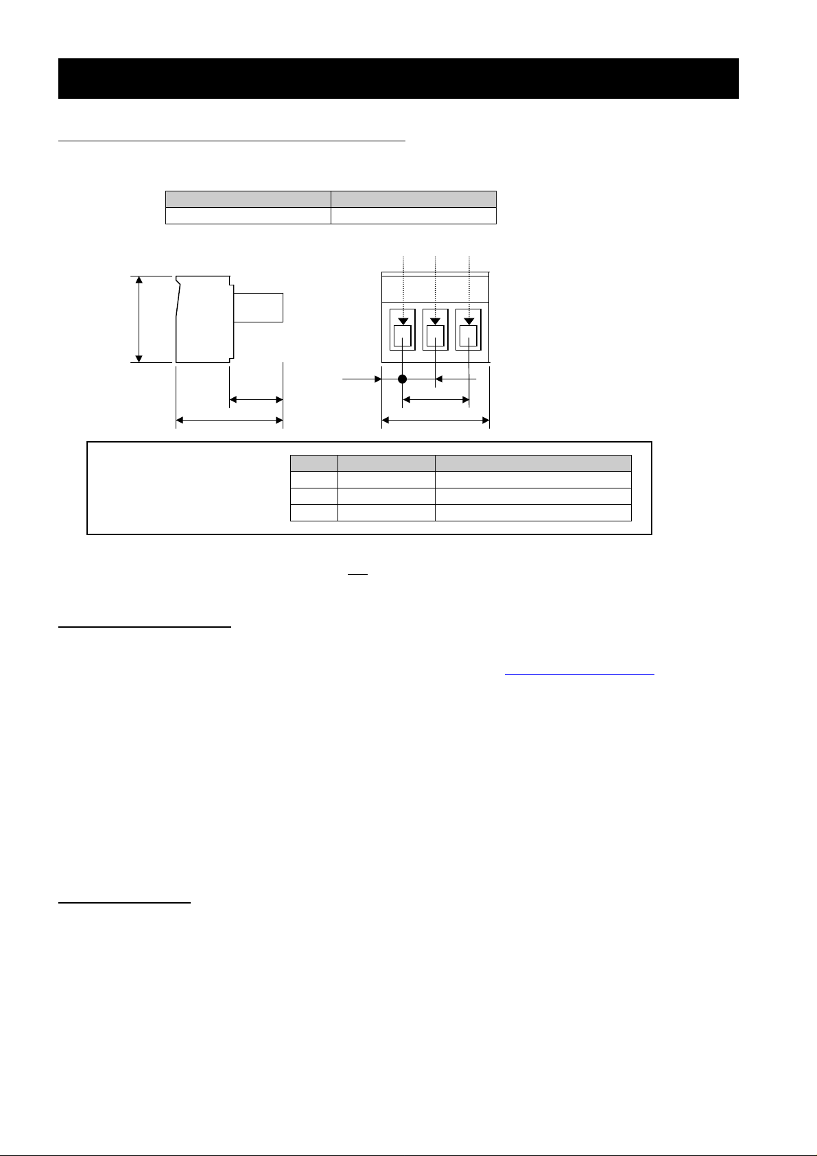
3.1 Connection for LonWorks connector
The SJ-LW connects t o the LonWorks net work wit h a 3- pin c onn ec tor. For the p in l a yout , ref er to Fi gu r e 3-1.
Cablesideconnector(attache dconnector)
Maker Type
Phoenix contact co, Ltd. MC 1.5/3-ST-3.81
Dimensio n
11.1
6.6
15.5
Wiring of LonWorks
Communication connector
Figure 3-1 Connector specification
NOTE : NET A and NET B connection is not polarity sensitive.
Pin No. 1 2 3
2.3
No. Signal mark Function
1 Shield Shield connection
2 NET A LonWorks NET A connection
3 NET B LonWorks NET B connection
3.2 Network cabling
3.8
7.62
12.22
Dimensio n i n mm
For detailed information about recommended cables for a LonWorks network, please see the FTT-10A Free
Topology Transceiver User’s Guide (doc.id.078-0156-01F) available at http://www.echelon.com
Below are some recommended cables :
-Belden 85102, unshielded
-Belden 8471, unshielded
-Level IV 22AWG, unshielded
-JY (St) Y 2x2x0.8, shielded
-TIA568A Cat.5 24AW G
Note) To be able to communicate in a noisy environment, and to fulfil all EMC-requirements, it’s
important that a shielded cable is used, and that proper grounding is provided.
3.3 Wiring note
1.Installing the cable to Network connector must be done after checking the power supply off.
2.Wiring should not have bare cables exposed between connector contacts.
3.Network cables should be fixed without tension. Cables fixed under tension have potential of causing a
communication fault by to be removed a connector.
4.Ensure external emergency stop measures are taken to stop the inverter, in the event of a network fault.
(a) Remove the Power supply of the Inverter when the network master detects a communication fault.
(b) When the m aster d etects a com m unicat ion f ault, turn on the intellig ent input terminal which would be
allocated (FRS), (RS) and/or (EXT) function.
6
Page 11

CHAPTER 4 SETTING
4.1 Setting of controlling frequency and start/stop commands
The Hitachi SJ300/L300P inverters can be configured to take reference set-points and commands from
several different locations. Re fer to the ta ble below for info rmation of how t o configu re the inve rter so that the
Lonworks controls frequency and the commands.
Command Function Setting range Setting data
A001
A002
Frequency
setting selection
Operating mode
selection
00(Volume)/01(Terminal)/02(Operator)
03(Rs485)/04(Option1)/05(Option2)
01(Terminal)/02(Operator)/03(Rs485)
04(Option1)/05(Option2)
02(Operator)
01(Terminal)
4.2 Network termination (S2)
The SJ-LW option board provides internal termination of the LonWorks network. To enable/disable the
termination a switch (S2) is used. See Figure 1-1 for location of the switch. The following table explains the
possible switch-settings :
Switch-position Termination type
FT Free topology termination enabled
NO Termination disabled
BUS Bus topology termination enabled
For more information about termination, see the FTT-10A Free Topology Transceiver User’s Guide
(doc.id.078-0156-01F) available at http://www.echelon.com
Note) Risk of equipment damage exists. The SJ-LW contains ESD (Electrostatic Discharge) sensitive
parts that can be damaged if you do not follow ESD control procedures. Static control precautions
are required when handling the adapter.
4.3 Service pin (S1)
The SJ-LW option board provides one Service pushbutto n (S1 ), which i s used d uring the i nstalla tion pha se to
identify the node. See Figure 1-1 for location of the pushbutton.
The SJ-LW is installed in a LonWorks network using any standard LonWorks installation tool.
(i.e. “LonMaker for Windows” from Echelon).
4.4 Baudrate
The SJ-LW has a fixe d bau dr at e of 78k bps (F TT -10 A).
7
Page 12

CHAPTER 5 LONWORKS COMMUNICATION FUNCTION
5.1 Operating the drive via Lon Mark profile
A LonMark profile defines a functional profile for a node communicating with others. A LonMark profile
specifies which SNVT’s and SCPT’s to be used and also a semantic meaning about the information being
communicated.
When a prof ile is imp lemen ted in a nod e, it is call ed a Lo nMa rk Objec t. O ne node can have s evera l obj ects
implemented. The SJ300 LonWorks adapter has two objects, a node-object and a drive-object. The nodeobject is used to control the other objects in a node.
(1)NodeObject
(1)NodeObject
(1)NodeObject(1)NodeObject
NodeObject
(2)Drive Object
(2)DriveObject
(2)DriveObject(2)DriveObject
nviRequest
nv1
SNVTobjrequest
nv1
nv2
nv18
nv16
nv3
nv4
nv17
Mandatory
Network
Variables
VariableSpeedMotor
Drive:6010
Mandatory
nviDrvSpeedStpt
SNVTswitch
Variables
Optional
nviDrvSpeedScale
SNVTlevpercent
nviWriAdr
SNVTcount
nviWriValue
UNVTsj300
nviInvSetFreq
SNVTfreqhz
nviEmergOverride
SNVThvacemerg
nviRdAdr
SNVTcount
ManufacturerDefinedConfigurationProperties
Variables
ConfigurationProperties
ConfigurationProperties
ConfigurationPropertiesConfigurationProperties
nc17‑nciLocation(optional)
nc50‑nciMaxSpeed(mandatory)
nc53‑nciMinSpeed(mandatory)
nc48‑nciRcvHrtBt(optional)
nc49‑nciSndHrtBt(mandatory)
nc52‑nciMinOutTm(optional)
nc158‑nciNmlSpeed(mandatory)
nc159‑nciNmlFreq(mandatory)
nc160‑nciRampUpTm(mandatory)
nc161‑nciRampDownTm(mandatory)
nc162‑nciDrvSpeedScale (optional)
Manufacturer
Variables
nc1‑nciPwUpOutTm(optional)
Network
Network
Defined
Network
nv2
nv5
nv6
nv9
nv8
nv10
nv7
nv11
nv15
nv12
nv13
nv14
nvoDrvSpeed
SNVTlevpercent
nvoDrvCurnt
SNVTamp
nvoDrvVolt
SNVTvolt
nvoDrvPwr
SNVTpowerkilo
nvoDrvRunHours
SNVTtimehour
nvoDrvStatus
UNVTsj300
nvoFreqAct
SNVTfreqhz
nvoParam
UNVTSJ300
nvoEmergStatus
SNVThvacemerg
nvoDrvAlarm
SNVTswitch
nvoDrvWarning
SNVTswitch
nvoStatus
SNVTobjstatus
8
Page 13

CHAPTER 5 LONWORKS COMMUNICATION FUNCTION
5.2 Input Network Variables (nvi’s)
5.2.1 Node object request (SNVT_obj_request nv iOb jRequest)
This input is used to enable control commands and updates from network.
The valid iden tif ic at io n num b ers mus t be us ed. The v al id num bers ar e 0 and 1.
The status of the node is reported in nvoObjStatus, see chapter 5.3.1.
Value Identifier Function
0 RQ_NORMAL enable settings of nviDrvSpeedStpt and nviDrvSpeedScale
again, if they were disabled by RQ_DISABLED. Speed
settings need to be updated to start the inverter again if
disabled.
1 RQ_DISABLED disables settings of nviDrvSpeedStpt and
nviDrvSpeedScale. It also stops the inverter.
2 RQ_UPDATE_STATU S updates nvoObjStatus
5 RQ_REPORT_MASK reports supported requests in nvoObjStatus
7 RQ_ENABLE enable settings of nviDrvSpeedStpt and nviDrvSpeedScale
again, if they were disabled by RQ_DISABLED. Speed
settings need to be updated to start the inverter again if
disabled.
9 RQ_CLE AR _STATUS clears n voO bj Sta tus
10 RQ_CLEAR_ALARM resets a fault (trip) in the drive
13 RQ_MANUAL_CTRL can be used when the inverter only want to be monitored
from Lon Network, not controled. No message containing a
WRITE_DEMAND_CODE (0x02) in the FrameType f ield of
the Hitachi high-speed serial protocol will be communicated
to the inverter from the option card. All messages with other
FrameType codes will be sent to the inverter.
14 RQ_REMORT_CTRL allow WRITE_DEMAND_CODE(0x02)
messages to be communicated to the inverter.
If RQ_SELF_TEST, RQ_OVERRIDE, RQ_RMV_OVERRIDE, RQ_ALARM_NOTIFY_ENABLED,
RQ_ALARM_NOTIFY_DISABLED, RQ_PROGRAM or RQ_NUL is requested, the invalid_request bit will be
set in nvoObjStatus.
Which request of RQ_DISABLED, RQ_NORMAL or RQ_ENABLE is set last is remembered. This means that
nviObjRequest can first be set RQ_DISABLED and then e.g RQ_REPORT_MASK. Then it is still disabled
but reported masks will be shown in nvoObjStatus.
Which requ est of RQ_M ANUAL_CT RL or RQ_RE MOTE_CTRL is set last is remember ed. This m eans that
nviObjRequest can first be set RQ_MANUAL_CTRL and then e.g RQ_REPORT_MASK. Then it is still in
manual control but reported masks will be shown in nvoObjStatus.
With regard to RQ_MANUAL_CTRL and RQ_REMOTE_CTRL, please refer chapter 6.8.
5.2.2 Drive Speed Setpoint (SNVT_switch nviDrvSpeedStp t),
5.2.3 Inverter frequency sett in g (SNVT_f req_hz nviIn vSetFre q)
This input network variable provides a low-resolution speed setpoint.
When nv iD r v S p e ed S t pt.State i s set to ze ro the dr i v e is stopped using ramp 1 (Normal Stop).
Following two methods are used for setting frequency.
(1) nviInvSetFreq = 0x7FFF (D efault)
It is possible to set the request speed by using ratio of Nominal Frequency (Refer to chapter 5.4.6) or
Nominal Speed (Refer to chapter 5.4.5).
(2) nviInvSetFreq = 0 to 400,
I
t is possible to set 0 to 400Hz to nviInvSetFreq directly.
9
Page 14

CHAPTER 5 LONWORKS COMMUNICATION FUNCTION
NviInvSetFreq
0x7FFF
(Initial value)
0〜400Hz
Note: Requested speed will not be greate r then th e valu e de fined by n ciMaxSpeed (Refer to chapte r 5.4. 8) o r
less then t he v al ue d ef ined b y nci Min Sp eed ( R efer to c h apt er 5. 4. 7).
*1:nviDrvSpeedScale = 100, Direction: Forward
= -100, Direction: Reverse
= When a value in nviDrvSpeedScale is set any value except for 100 and –100, i t
Default value:
Default value is AUTO (state = 0xFF). T his value will be adapted at power-up. This network variable input
may use the Receive Heartbeat function depending on if Receive Heartbeat function is setup for use. The
actual value of drive speed does also depend on nviDrvSpeedScale.
NviDrvSpeedStpt
State Value
0xFF N/A N/A AUTO(Invalid)
0 N/A N/A
1 0 0% 0%
1
1 201 〜255 100.0% 100.0%
0xFF N/A N/A AUTO(Invalid)
0 N/A N/A
1 N/A N/A nviInvSetFreq *1
1〜200 0.5〜100.0 % nciNmlFreq*nviDrvSpeedSpt
becomes the stop command (Run: Deceleration stop, Stop: Maintain to stop).
Setting ratio Request speed
Stop st at e
*nviDrvSpeedScale
Stop st at e
Scaling: See chapter 6.1.4
5.2.4 Speed Setpoint Scaling (SNVT_lev_percent nviDrvSpeedScale)
This input network variable provides scaling for nviDrvSpdStpt. For example if nviDrvSpeedStpt value is
100% and nviDrvSpeedScale value is -150%, then actual speed setpoint value is -15 0% meaning reverse 1,5
times nominal speed. The requested speed will not be greater than the value defi ned by nciMaxSpeed or
less than t he v al ue d ef ined b y nci Min Sp eed.
Depending on Drive Speed Setpoint, behavior of Speed Setpoint Scaling will be changed. Followings are
explanation of behavior.
(1) nviInvSetFreq = 0x7FFF(Initial value)
It prescribes the scaling for Drive Speed Setpoint (Refer to chapter 5.2.2).
(2) nviInvSetFreq = 0 to 400
It sets direction of rotation.
nviDrvSpeedScale = 100, Direction: Forward
= -100, Direction: Reverse
= When a value in nviDrvSpeedScale is set any value except for 100 and –100, i t
becomes the stop command (Run: Deceleration stop, Stop: Maintain to stop).
Example (1): nviInvSetFreq = 0x7FFF
For example if nviDrvSpeedStpt value is 100% and nviDrvSpeedScale value is -150%, then actual speed
setpoint value is -150% meaning reverse 1,5 times nominal speed (Refer to chapter 5.3.6).
Also refer to 6.1.4.
10
Page 15

CHAPTER 5 LONWORKS COMMUNICATION FUNCTION
Example (2) : nviInvSetFreq = 0 to 400
When nviI n vSet Fr eq is at 60H z and nviDrvSpeedScale is 100%, the inverter is in forward run at 60Hz.
Valid Range: -163.84 to163.83%
Default Value: Is defined by nciDrvSpeedScale (Refer to 5.4.14).
Scaling: See chapter 6.1.4
5.2.5 Emergency Override (SNVT_hvac_emerg nviEmergOverride)
When EMER G_S HUTD OW N c omm and is inputted, the inverter executes the deceleration stop and also the
value in EMERG_SHUTDOWN is supported but the other values are not supported.
(Deceleration time is dependant on Ramp Down Time (Refer to chapter 5.4.10))
Value Definition Contents Support
0 EMERG_NORMAL
1 EMERG_PRESSURIZE
2 EMERG_DEPRESSURIZE
3EMERG_PURGE
4EMERG_SHUTDOWN
5EMERG_FIRE
0xFF EMERG_NUL
Noemergencymode
Emergencypressurize
Emergencydepressurize
Emergencypurgemode
Emergencyshutdown
−
Valuenotavailable
Yes
No
No
No
Yes
No
No
11
Page 16

CHAPTER 5 LONWORKS COMMUNICATION FUNCTION
5.3 Output Network Variables - nvo’s
5.3.1 Node Object Status (SNVT_obj_status nvoObjStatus)
This nvo reports node object status. It will be updated every time status change. See chap. 5.1.1 for different
requests.
Identifier Status
Invalid_request The node has been asked for an unsupported request.
Report_mask Report supported fields.
Comm_failure No contact with SJ300/L300P.
In_alarm The SJ300/L300P inverter is tripped.
Disabled NviObjRequest have received a RQ_DISABLED request. Settings of
nviSpeedScale and nviSpeedStpt is disabled.
Manual_control SJ300/L300P is not controlled from the option card.
See digital operator value at A001 (should be 02 to avoid manual control to be
set) and A002 (should be 01 to avoid manual control to be set). Manual_control
will be set if option-board isn’t in control over one parameter. O ption card can
still give or der wh er e it h as com m and .
It will be set if NviObjRequest have received a RQ_MANUAL_CTRL request.
Invalid ID If another identification number then 0 and 1 have been set in request by SNVT
nviObjRequest. The request will not be carried out.
5.3.2 Drive Status (UNVT_sj300 nvoDrvStatus)
This output network variable provides the status of the drive.
The first three bytes will be mapped directly from the information received at address 0xFFFF8E10 in the
SJ300/L300P. If tripped, the last byte will contain an error code read from where pointer of last trip
(0x08000363) points too.
data format :
Status A Status B Status C Status D
Status C : Lad mode
Status A: Inverter status 1
Value State
00 initial status
01 ---02 On stopping
03 On running
04 On FRS
05 On JG
06 On DB
07 On reading frequency
08 On retrying
09 On UV
10 On TRIP
11 On waiting reset
Value State
00 --01 Stop
02 Deceleration speed
03 Constant speed
04 Acceleration speed
05 Forward
06 Reverse
07 Reverse from forward
08 Forward from reverse
09 Forward start
10 Revers e start
Status B: Inverter status 2
Value State
00 On stopping
01 On running
02 On tripping
Status D: trip code (see chapter 6.3)
12
Page 17

CHAPTER 5 LONWORKS COMMUNICATION FUNCTION
5.3.3 Drive Current (SNVT_amp nvoDrvCurnt)
This outp ut net wor k var ia ble pro vi des th e dr ive out p ut cu rr en t in Am ps.
5.3.4 Drive Speed (SNVT_level_percent nvoDrvSpeed)
This output network variable provides the speed of the drive as a percentage of the nominal speed. Since
nominal speed and nominal frequncy are tightly connected to eachother, the out value is calculated on the
nominal (base) frequency and the running (out) frequency. This output network variable is used as a
heartbeat to monitor the health of the LonWorks communication interface. See chapter 5.3.1 about
heartbeats.
Scaling:
If value of present running is forward then run_dir will be1.
If value of present running is reverse then run_dir will be -1.
BASE_FREQ / ((raw data format)OUT_FREQ / 1000) * (run_dir) = nvoDrvSpeed
5.3.5 Drive Power (SNVT_power_kilo nvoDrvPwr)
This output network variable provides the drive power in kilowatts.
5.3.6 Drive voltage (SNVT_volt nvoDrvVolt)
This output network variable provides the drive voltage in volts.
5.3.7 Output Frequency (SNVT_fre q_hz n voFreqA ct)
Output frequency in Hz. Always positive, i.e. no information about direction of revolution (forward/reverse).
5.3.8 Operation Hour Counter (SNVT_time_hour nvoDrvRun Hours)
Total power on time in whole hours.
5.3.9 Parameter value out (SNVT_count_inc nvoParam)
Used as feedback variable for generic parameter requests. See nciRdAdr (chapter 5.3.13), nciWriAdr
(chapter 5.3.11) and nciWriValue (chapter 5.3.12).
5.3.10 Emergency Status (SNVT_hvac_emerg nvoEmergStatus)
It indicates emergency stop status. Emergency stop state (nvoEmergStatus) is indicated as
EMERG_ SHUT DOWN while em er g ency stop com m and (nvi Em er gO ver ri de) is EME R G_S HUT DOWN.
Value Definition Contents Support
0 EMERG_NORM AL No emer ge nc y mo de Ye s
1 EMERG_PRESSURIZE Emergency pressurize No
2 EMERG_DEPRESSURIZE Emergency depressurize No
3 EMERG_PURGE Emergency purge mode No
4 EMERG_SHUTDOWN Emergency shutdown Yes
5EMERG_FIRE
0xFF EMERG_NUL Value not available No
−
No
5.3.11 Drive Alarm (SNVT_switch nvoDrvAlarm)
5.3.12 Drive Warning (SNVT_switch nvoDrvWarning)
It is defined as Drive Alarm: when an inverter trip occurs, Drive Warning: when an inverter warning occurs,
and then output the warning state.
Trip Warning
Yes No 1 100(%) 0 0(%) Drive Alarm
No Yes 0 0(%) 1 100(%) Drive Warning
Yes Yes 1 100(%) 1 100(%) Drive Alarm and Warning
No No 0 0(%) 0 0(%) No warning
NvoDrvAlarm nvoDrvWarning
State value state value
13
Contents
Page 18

CHAPTER 5 LONWORKS COMMUNICATION FUNCTION
5.4 Configuration Properties - nc i’s
If an nci has a corresponding parameter in the inverter it will be written to with the value of the nci at some
occations, apart from when nci is update from network. These occations are when:
-Node is brought online
-Inverter is power-cycled
-Inverter is tripped and error is reset from LonWorks option card
-If there is a communication error between neuron chip and option board host processor
This means that if setting e.g. F002 (Ra mp up ti me) fro m the D.O. to e.g . 3 sec will be set to 3 sec until an y of
these things happen. To ensure that these parameters have the values intended, set them from the option
board.
5.4.1 Send Heartbeat (SNVT_time_sec nciSndHrtBt)
This input configuration network variable provides the maximum send time for the variable nvoDrvSpeed.
Default value = 0 (disabled).
5.4.2 Receive Heartbeat (SNVT_time_sec nciRcvHrtBt)
This configuration property is used to control the maximum time that elapses between updates of the input
network variable nviDrvSpe edStpt. If timeout occurs, the module will trip the inverter by setting
OPT1(2)_TRIP_N low.
The valid range is any value between 0.0 sec and 6,553.4 sec. Setting nciRcvHrtBt=0 disables the Receive
Heartbeat mechanism. Default value is 0.
5.4.3 Minimum Send Time (SNVT_time_sec nciMinOutTm)
This input configuration network variable control the minimum period of time that expires before the network
output variables can be resent. This is good for limiting use of bandwidth on the LonWorks channel.
The valid range is any value between 0.0 to 6,553.4 secs. Setting nciMinOutTm = 0 disables transmission
limiting.
Default va lu e = 0.
5.4.4 Location Label (SNVT_str_asc n ciLo cation)
This configuration property can optionally be used to provide more descriptive physical location information
than can be provided by the Neuron Chip’s 6-by te location string. The loca tion relates to the ob ject and not t o
the node.
Default va lu e = em pt y sp ac es.
5.4.5 Motor Nominal Speed (SNVT_rpm nciNmlSpeed)
This configuration property can be used for setting the base frequency (Range of setting: 30 to 400Hz or
equivalent frequency).
Base frequency(Hz)=the number of rotation(min
-1
)*the number of motor poles/120
Initial value is the value which is set at first base frequency: A003. If data is changed, it will be reflected to
A003.
Inverter parameter P049 is used for setting the number of motor poles.
14
Page 19

CHAPTER 5 LONWORKS COMMUNICATION FUNCTION
5.4.6 Nominal Frequency (SNVT_freq_hz nciNmlFreq)
This configuration property is used to provide the nominal frequency of the motor. This value is necessary to
determine the minimum and maximum frequency.
Default va lu e: 50 Hz
5.4.7 Minimum Speed (SNVT_lev_percent nciMinSpeed)
This configuration property is used to define the minimum speed of a motor. It’s value is entered as a
percent of nominal frequency, as defined by the Nominal frequency (nciNmlFreq) configuration value. Set
this parameter when drive is stopped for be st resul t, sin ce thi s i s a w rite pr ote cted p ara meter in SJ300/L300P
when drive is running. If parameter is set when running it will only be saved in optionboard and not in drive.
If the running ordered frequency is lower then nciMinSpeed, ordered frequency will not be highered.
NciMinSpeed will be in effect on the next frequency setting.
If nciNmlFreq = 50Hz and nciMinSpeed = 10%, the minimum frequency is 5Hz.
-163.84 ≤ minimum speed ≤ maximum speed ≤ 163.83
Default value: 0%
5.4.8 Maximum Speed (SNVT_lev_percent nciMaxSpeed)
This configuration property is used to define the maximum speed of a motor. It’s value is entered as a
percent of nominal speed, as defined by the Nominal Speed (nciNomSpeed) configuration value. Set this
parameter when drive is stopped for best result, since this is a write protected parameter in SJ300/L300P
when drive is running. If parameter is set when running it will only be saved in optionboard and not in drive.
If the running ordered frequency is higher then nciMaxSpeed, ordered frequency will not be lowered.
NciMaxSpeed will be in effect on the next frequency setting.
If nciNmlFreq = 50Hz and nciMaxSpeed = 125%, the maximum frequency is 65.5Hz.
The value of the maximum speed must be validated against the value of the minimum speed as follows:
-163.84 ≤ minimum speed ≤ maximum speed ≤ 163.83
Default value: 100%
5.4.9 Ramp Up Time (SNVT_time_sec nciRampUpTm)
This configuration property is used to set the ramp up time.
Default va lu e: 30 Sec
5.4.10 Ramp Down Time (SNVT_time_sec nciRampDownTm)
This configuration property can optionally be used to provide to set the ramp down This configuration
property is used to set the ramp up time.
Default va lu e: 30 Sec
5.4.11 Generic Parameter address setting, Write (SNVT_count nciWriAdr)
Chooses the parameter address (16 bits) to be w ri tten to t h e drive. Addre sses i n the 0 xFFFF**** area can not
be reached.
Valid range: See SJ300/L300P manual.
15
Page 20

CHAPTER 5 LONWORKS COMMUNICATION FUNCTION
5.4.12 Parameter value, Write (UNVT_sj300 nciWriValue)
This nci is used as a value input for the user selected parameter nciWriAdr. The SCPT uses the following
format:
struct{
unsigned long int lowWord; //Used for byte and word data
unsigned long int highWord; //Used for highWord when
transmitting 4 byte data
}UNVT_sj300
Scaling is defined in SJ300/L300P user’s manual.
5.4.13 Generic Parameter address setting, Read (SNVT_coun t nc iRdAdr)
Chooses the parameter address (16 bits) to be read from the drive. Addresses in the 0xFFFF**** area can
not be reached.
Default value: 0x0070
Valid range: See SJ300/L300P manual.
5.4.14 Speed setpoint scaling default value (SNVT_ lev_percent)
This parameter is used for setting its value to nviDrvSpeedScale (see chapter5.1.3) on every startup.
Default value : 0
Valid range : -163-163%
5.4.15 Power Up Out Time (SNVT_time_sec nciPwUpOutTm)
When the p ower is ON, the inv er te r a nd P C do not com m unic a te e ac h ot her d ur ing se tt ing tim e.
This setting is used for avoiding data collision, when the power is ON.
16
Page 21

CHAPTER 6 CONTROL FROM LONWORKS
6.1 Conditions for operating
This section will decsribe what conditions there are for performing some common actions and how the
combination of SNVTs and SCPTs will affect the operation of the SJ300/L300P inverter.
6.1.1 General
Communication and configuation of LonWorks optionboard and SJ300/L300P must be set up and function
properly. See manuals on both subjects.
Note: The SJ300/L300P parameter A001 must be set to 02 and A002 must be set to 01 if drive is to accept
frequency settings or/and start/stop commands from LonWorks optionboard.
6.1.2 Start
The inverter will output a frequency if nviDrvSpeedStpt.value is greater than zero, nviDrvSpeedStpt.state
isn’t zero and nviDrvSpeedScale isn’t zero. RQ_NORMAL or RQ_ENABLE has to be requested more
recently then RQ_DISABLED. RQ_REMOTE_CTRL has to be requested more recently then
RQ_MANUAL_CTRL. Node has to be online.
6.1.3 Stop
The inverter will stop and use the normal stop ramp if NviSpeedStpt.state is set to any value different from 1
or if node is brought offline. The inverter will aslo stop if RQ_DISABLED or RQ_MANUAL_CTRL is requested
in nviObjRequest or if saving to inverter EEPROM, using using 0xFFFF in nviWriteAdr.
6.1.4 Frequency setting
Followings describe two methods for setting frequency.
(1) nviInvSetFreq = 0x7FFF(Initial value)
It is possible to set request speed by using ratio of Nominal Frequency (Refer to chapter 5.4.6) or
Nominal Speed (Refer to chapter 5.4.5).
The formula below is calculation of frequency.
Frequency setting(Hz)=nviDrvSpeedStpt.value(%)×nviDrvSpeedScale(%)×nciNml Freq(Hz)
(2) nviInvSetFreq = 0 to 400,
It is possible to set 0 to 400Hz to nviInvSetFreq directly.
Example below indicates frequency setting.
(1) nviInvSetFreq = 0x7FFF(Initial value)
NviSpeedScale
0% 0% 1 0Hz Forwar d comman d
100% 0% 1 0Hz Forward command
0% 100% 1 0Hz Forward command
150% 100% 0 1.5*1.0* nciNmlFreq Stop command
150% 100% 1 1.5*1.0* nciNmlFreq Forward command
-75% 100% 1 -0.75*1.0* nciNmlFreq Reverse command
150% 50% 1 1.5*0.50* nciNmlFreq Forward command
NviSpeedStpt
value state
Frequency setting Operation command
17
Page 22

CHAPTER 6 CONTROL FROM LONWORKS
( 2) In cas e of nv iIn vS etFre q = 0 to 4 00
NviSetFreq NviSpeedScale
50Hz 100% N/A 0 nviInvSetFreq Stop command
30Hz 100% N/A 1 nviInvSetFreq Forward command
60Hz 100% N/A 1 nviInvSetFreq Forward command
50Hz
60Hz
30Hz 99% N/A 1 nviInvSetFreq Stop command
30Hz
−100%
−100%
−99%
NviSpeedStpt
value State
N/A 1 nviInvSetFreq Reverse comm and
N/A 1 nviInvSetFreq Reverse comm and
N/A 1 nviInvSetFreq Stop comm and
Frequency setting Operation command
6.1.5 Write value to an address
1. Change address in nciWriAdr.
2. Change value in nciWriValue.
It is the changing of value in nciWriValue that triggers writing to an address in SJ300/L300P. This means that
just changing address alone will not perform a writing sequence.
To be sure that SJ300/L300P has accepted the value written to it, read it back with setting nciRdAdr to the
same address as nciWriAdr. See SJ300/L300P manual or chapter 4 for a description of available adresses.
Only addresses in the 0x0800**** area can be reached.
This parameter is also used for saving values set from option board in SJ300/L300P EEPROM. See chapter
6.2 for more details.
Address wanted NciWriAdr NciWriValue Result
0x08000000 0x0000 0 “1st setting multispeed frequency 0” set
to zero
Other val id ad dr es s Last two b ytes of
valid address
Other val id ad dr es s Last two b ytes of
valid address
Access inhibited
area
Save to
SJ300/L300P
EEPROM
Last two bytes of
access inhibited
area
0xFFFF Any (but writing
Valid value Address written to with value
Unvalid value
Value
needed to
compleat
sequence).
Address written to with unvalid value.
SJ300/L300P take cares of unvalid
values.
Address written to with value.
SJ300/L300P take cares of access
inhibited addresses.
Saving values set from option board in
SJ300/L300P EEPROM.
18
Page 23

CHAPTER 6 CONTROL FROM LONWORKS
6.1.6 Read value from an address
The address set in nciRdAdr will be polled and result will be written to nvoParam as often as value on
address changes or the workload on the host application and nciMinOutTime allows.
If nciRdAdr is set to 0 x007 0 it will not load the ne twork wi th i n formati on not wan ted or need ed for th e momen t.
This is recommended to minimalize network load. Addresses in the 0xFFFF**** area can not be read.
0x08000070 is an area in SJ300/L300P where access is inhibited. There are other areas in SJ300/L300P
were access is inhibited but if such address is set it to nciRdAdr the option board will try to read it anyway.
See appendix 1 for a list of valid addresses.
Default value: 0x08000070 (Access Inhibited in SJ300/L300P)
Address wanted Nc i RdAdr NvoParam
0x08000070 0x0070 Zero or latest polled value , not updated
Other access inhibited area
Valid address Valid address Polled from SJ300, continuously updated
Other access inhibited
area
Polled from SJ300, continuously updated
6.1.7 Reset fault
If an error has occured SJ300/L300P will trip. By removing the reason for tripping and setting nviObjRequest
to RQ_CLEAR_ALARM it can be reset.
6.1.8 Prioritation between nciMinOutTm and nciSendHrtBt
The nciMinOutTm will have prioritation over nciSendHrtBt. This will mean that heartbeats will not be sent as
often as specified in nciSendHrtBt if nciMinOutTm has a longer time set.
6.2 Save data in SJ300/L300P EEPRO M
To store parameter values set from option board in SJ300/L300 between power-cycles they have to be saved
in SJ300/L300P EEPROM.
Setting nciWriAdr to 0xFFFF (65535 decimal) and writing any value to nciWriValue will save parameters to
SJ300/L300P EEPROM.
NOTE : The inverter will be stopped using the normal stop ramp before saving, so it’s recommended to send
the save command only when inverter already is stopped.
The values set from option board will now remain the same after a boot sequence of the inverter.
There is no need to use the saving to EEPROM function when parameters are set from the digital operator
since they always are saved between power-cycles.
6.3 Optionboard Error han dling
If there is no response from SJ300/L300P on the serial channel in three messages in a row communication is
believed to be down.
Communication with LON is considered down if heartbeats aren’t received within nciRcvHrtBt time.
This will make SJ300/L300P trip.
19
Page 24

CHAPTER 6 CONTROL FROM LONWORKS
6.4 How to switch to operation command and f req uenc y co mmand
Table below indicates how to switch to operation command and frequency command by using the commands
in nviObjRequest. (Refer to chapter 4.1, 5.2.1 and 5.3.1)
nviObjRequest Command setting data Control and frequency setting
RQ_REMOTE_
CTRL
RQ_MANUAL_
CTRL
A001 = 02(Operator)
A002 = 01(Terminal)
Any data for A001 and A002
except above.
A001 = 02(Operator)
A002 = 01(Terminal)
Any data for A001 and A002
except above.
Comply with LonWork s.
Comply with A001 and A002.
Command setting mentioned as left.
Comply with A001 and A002.
6.5 Internal SJ300/L300P error codes
The malfunction codes are coded as follows. See chapter 5.3.2. Those error codes will be found in
the fourth byte of nvoDrvStatus.
Fault code SJ300/L300P Fault description
0 No fault
1 Overcur re nt dri ve.
2 Overcurrent deceleration.
3 Overcurrent acceleration.
4 Overcurrent.
5 Overload protection.
6 Braking resistor overload protection.
7 Over-voltage protection.
8 EEPROM error.
9 Under-voltage.
10 Current detector error.
11 CPU error.
12 External trip.
13 USP error.
14 Ground fault protection.
15 Incoming over-voltage protection.
16 Temporary power loss protection.
21 Abnormal temperature.
23 Gate allay error.
24 Open-phase error.
30 IGBT error.
35 Therm is tor error.
36 Abnorm al br ake.
60-69 Option 1 error 0-9.
70-79 Option 2 error 0-9.
20
Page 25

CHAPTER 7 COUNTERMEASURE FOR ABNORMALITY
7.1 Trip display
When the in vert er is in a tripped state, the inverter displays an error code (See table below). The trip history
monitor (d081 to d086) also displays the same error code as the inverter.
Trip code
Inverter’s running condition of trip d etect ed
7.2 Protection function list
The table below describes an error code for protecting the inverter and the motor.
Error Display in the table below, X is 6 (Error for option slot 1) or 7 (Error for option slot 2).
No. Function
1Lonworks
communic a ti on err or
2 Inverter communication
error
With regard to the other errors except table above, refer to Inverter instruction manual chapter 4 Explanation
of funct i o n.
Error
Display
EX0 This error is displayed, when disconnection occured, while
the inverter is operating with Lonworks.
EX9 This error is displayed, when communication timeout occurs
between the inverter and the option board.
Action
7.3 Countermeasure for a trip state
The table below only corresponds to additional trip codes, with regard to the other countermeasures refer to
Inverter instruction manual chapter 4 Explanation of function.
Trip code Name of tri p Cause Conformation Countermeasure
EX0 L on w o r ks
Communication
error
EX9 Inverter
communication
error
Defective connector
for signal cable
causes connection
fail.
Terminating resistor
is not connected.
Wiring distance does
not much with
baudrate.
Option board is
removed.
Check the ar ea of
Connection.
Check the
Connection
Check the wir in g
Distance
Check as
Mentioned left
Improve the connection and then
reset the power supply.
Connect the terminating Resistor
and then reset the power supply
Adjust the setting to the matching
Baudrate
Adjust wiring distance
Mount the option board again
and then secure it with screws.
21
Page 26

CHAPTER 7 COUNTERMEASURE FOR ABNORMALITY
7.4 LED display and Counter measur e
Following states are indicated by three LED's.
LED Color Function Countermeasure
Green Power on and CPU running
Red flashing Flash or RAM error
Power/
Status
LonWorks
Service
Serial
channel
status
Red Hardware error(if flashing red
together with Serial Status
LED, Wink command has been
received) or during initializing
inverter data.
Unlit Neuron Chip is
Configured/Normal Run mode
Flash Green
1Hz
Green Neuron Chip is Applicationless,
Green Serial channel status OK.
Flash Red
1Hz
Red No serial communication. (If
Neuron Chip is Unconfigured
(No Netwo rk co nfi gur a tio n)
Unrecoverable fault
Serial communication error. Confirm cable length and connection fails
flashing red together with
Power/Status LED, Wink
command has been received)
Need to change the SJ-LW.
(Back to green after initializing data)
Confirm system setting and adjust
adequate.
Need to change the SJ-LW.
of connector. And then adjust adequate.
Confirm cable length and connection fails
of connector. And then adjust adequate.
−
−
−
−
22
Page 27

APPENDIX PARAMETER OBJECT LISTS
APPENDIX1 Parameter cross-reference list
Address Size
H'08000000 4 0〜400.00Hz *100 1st setting Multispeed frequency 0 A020
H'08000004 4
H'08000008 4
H'0800000C 4
H'08000010 4 0〜400.00Hz *100 Multispeed frequency 2 A022
H'08000014 4
H'08000018 4
H'0800001C 4
H'08000020 4 0〜400.00Hz *100 Multispeed frequency 6 A026
H'08000024 4
H'08000028 4
H'0800002C 4
H'08000030 4 0〜400.00Hz *100 Multispeed frequency 10 A030
H'08000034 4
H'08000038 4
H'0800003C 4
H'08000040 4 0〜400.00Hz *100 Multispeed frequency 14 A034
H'08000044 4
H'08000048 4
H'0800004C 4
H'08000050 4 0〜400.00Hz *100 1st Lower limiter frequency A062
H'08000054 4
H'08000058 4
H'0800005C 4
H'08000060 4 0.01〜3600.00s *100 3rd Acceleration time 1 No F302
H'08000064 4
H'08000068 4
H'0800006C 4
H'08000070 4 - - Access Inhibited No H'08000074 4
H'08000078 4
H'0800007C 4 0.01〜3600.00s *100 3rd Acceleration time 2 No A392
H'08000080 4
H'08000084 4
H'08000088 4
H'0800008C 4 0〜400.00Hz *100 Start frequency of “O” terminaly A011
H'08000090 4
H'08000094 4
H'08000098 4
H'0800009C 4 0〜400.00Hz *100 Start frequency of “OI” terminal 0 A101
H'080000A0 4
H'080000A4 8 - - Access Inhibited No -
H'080000AC 4 0〜400.00Hz *100 Jumping frequency 1 A063
H'080000B0 4
H'080000B4 4
H'080000B8 4
H'080000BC 4 0〜400.00Hz *100 1st Frequency of 2-stage acceleration A095
H'080000C0 4
H'080000C4 4
H'080000C8 4
H'080000CC 4 0〜400.00Hz *100 Frequency of frequency matching b007
H'080000D0 4
Setting
range
0〜400.00Hz
0〜400.00Hz
0〜400.00Hz
0〜400.00Hz
0〜400.00Hz
0〜400.00Hz
0〜400.00Hz
0〜400.00Hz
0〜400.00Hz
0〜400.00Hz
0〜400.00Hz
0〜400.00Hz
0〜400.00Hz
0〜400.00Hz
0〜400.00Hz
0〜400.00Hz
0.01〜3600.00s
0.01〜3600.00s
0.01〜3600.00s
0.01〜3600.00s
0.01〜3600.00s
0.01〜3600.00s
0.01〜3600.00s
0.01〜3600.00s
0.01〜3600.00s
0.01〜3600.00s
0〜400.00Hz
-400.00〜400.00Hz
-400.00〜400.00Hz
0〜400.00Hz
0〜400.00Hz
0〜400.00Hz
0〜400.00Hz
0〜400.00Hz
0〜400.00Hz
0〜400.00Hz
0.01〜3600.00s
magn. Contents L300P
*100 2nd setting Multispeed frequency 0 A220
*100 3rd setting Multispeed frequency 0 No A320
*100 Multispeed frequency 1 A021
*100 Multispeed frequency 3 A023
*100 Multispeed frequency 4 A024
*100 Multispeed frequency 5 A025
*100 Multispeed frequency 7 A027
*100 Multispeed frequency 8 A028
*100 Multispeed frequency 9 A029
*100 Multispeed frequency 11 A031
*100 Multispeed frequency 12 A032
*100 Multispeed frequency 13 A033
*100 Multispeed frequency 15 A035
*100 1st Upper limiter frequency A061
*100 2nd Upper limiter frequency A261
*100 2nd Lower limiter frequency A262
*100 1st Acceleration time 1 F002
*100 2nd Acceleration time 1 F202
*100 1st Deceleration time 1 F003
*100 2nd Deceleration time 1 F203
*100 3rd Deceleration time 1 No F303
*100 1st Acceleration time 2 A092
*100 2nd Acceleration time 2 A292
*100 1st Deceleration time 2 A093
*100 2nd Deceleration time 2 A293
*100 3rd Deceleration time 2 No A393
*100 End frequency of “O” terminalal A012
*100 Start frequency of “O2” terminal 0 A111
*100 End frequency of “O2” terminalal A112
*100 End frequency of “OI” terminalal A102
*100 Jumping frequency 2 A065
*100 Jumping frequency 3 A067
*100 Frequency of stopping acceleration A069
*100 2nd Frequency of 2-stage acceleration A295
*100 1st Frequency of 2-stage deceleration A096
*100 2nd Frequency of 2-stage deceleration A296
*100 Deceleration time of Non-stop No b053
operator
code
23
Page 28

APPENDIX PARAMETER OBJECT LISTS
Address Size
H'080000D4 4
H'080000D8 4 0〜400.00Hz *100 Arrival frequency at deceleration1 C043
H'080000DC 4
H'080000E0 4
H'080000E4 12 - - Access Inhibited No H'080000F0 2
H'080000F2 2
H'080000F4 2
H'080000F6 2 0〜9.99Hz *100 J0gging frequency A038
H'080000F8 2
H'080000FA 2
H'080000FC 2
H'080000FE 2 - - Access Inhibited No -
H'08000100 4
H'08000104 4
H'08000108 4 0〜65.530
H'0800010C 4
H'08000110 4
H'08000114 4
H'08000118 4 0〜655.35A *100 1st No load current Io of motor No H023
H'0800011C 4
H'08000120 4
H'08000124 4
H'08000128 4
H'0800012C 4
H'08000130 4 0〜65.530
H'08000134 4
H'08000138 4
H'0800013C 4
H'08000140 4
H'08000144 4
H'08000148 4
H'0800014C 4
H'08000150 2
H'08000152 2 0〜50.0% *10 2nd Break point of manual torque boost A243
H'08000154 2
H'08000156 2
H'08000158 2
H'0800015A 2
H'0800015C 2
H'0800015E 2
H'08000160 2
H'08000162 2 0〜60.0s *10 Time of stopping to accelerate A070
H'08000164 2
H'08000166 2
H'08000168 2
H'0800016A 2 0〜100.0 *10 Response time of Energy saving functio n A086
H'0800016C 2 - - Access Inhibited No H'0800016E 2
Setting
range
0〜400.00Hz
0〜400.00Hz
0〜400.00Hz
30〜400Hz
30〜400Hz
30〜400Hz
30〜400Hz
30〜400Hz
30〜400Hz
0〜65.530
0〜65.530
0〜65.530
0〜655.35mH
0〜655.35mH
0〜655.35A
0.001
9999.000kgm2
0.001
9999.000kgm2
0〜65.530
0〜65.530
0〜65.530
0〜655.35mH
0〜655.35mH
0〜655.35A
0〜655.35A
0.001
9999.000kgm2
0.001
9999.000kgm2
0〜50.0%
0〜50.0%
0〜60.00Hz
0〜60.0s
0〜60.0s
0〜10.00Hz
0〜10.00Hz
0〜10.00Hz
0〜3600.0s
0〜100.00
0.01〜99.99%
0.3〜100.0s
Ω
Ω
Ω
Ω
〜
〜
Ω
Ω
Ω
Ω
〜
〜
magn. Contents L300P
operation at Instantaneous power failure
*100 Arrival frequency at acceleration1 C042
*100 Arrival frequency at acceleration2 No C045
*100 Arrival frequency at deceleration2 No C046
*1 1st Base frequency A003
*1 2nd Base frequency A203
*1 3rd Base frequency No A303
*1 1st Maximum frequency A004
*1 2nd Maximum frequency A204
*1 3rd Maximum frequency No A304
*1000 1st Primary resistor R1 of motor No H020
*1000 2nd Primary resistor R1 of motor No H220
*1000 1st Secondary resistor R2 of motor No H021
*1000 2nd Secondary resistor R2 of motor No H221
*100 1st Inductance L of motor No H022
*100 2nd Inductance L of motor No H222
*100 2nd No load current Io of motor No H223
*100 1st Inertia J of motor No H024
*100 2nd Inertia J of motor No H224
*1000 1st Primary resistor R1 of motor (Auto) No H030
*1000 2nd Primary resistor R1 of motor (Auto) No H230
*1000 1st Secondary resistor R2 of motor (Auto) No H031
*1000 2nd Secondary resistor R2 of motor (Auto) No H231
*100 1st Inductance L of motor (Auto) No H032
*100 2nd Inductance L of motor (Auto) No H232
*100 1st No load current Io of motor (Auto) No H033
*100 2nd No load current Io of motor (Auto) No H233
*100 1st Inertia J of motor (Auto) No H034
*100 2nd Inertia J of motor (Auto) No H234
*10 1st Break point of manual torque boost A043
*10 3rd Break point of manual torque boost No A343
*100 Frequency of DC braking start A052
*10 Time of DC braking working A055
*10
*100 Width of jumping frequency 1 A064
*100 Width of jumping frequency 2 A066
*100 Width of jumping frequency 3 A068
*10 Integrate (I) gain of PID control A073
*100 Differential (D) gain of PID control A074
*100 Scale of PID control A075
*10 Waiting time of retry b003
Time of DC braking working for beginning of
inverter running
operator
code
A058
24
Page 29

APPENDIX PARAMETER OBJECT LISTS
Address Size
H'08000170 2
H'08000172 2
H'08000174 2 20.0〜120.0 *10 Level of 3rd Electronic thermal protection No b312
H'08000176 2
H'08000178 2
H'0800017A 2
H'0800017C 2 0〜1000.0A *10 Free electronic thermal current 2 b018
H'0800017E 2
H'08000180 2
H'08000182 2
H'08000184 2 0.0〜800.0V *10 Free V/F control voltage 1 b101
H'08000186 2
H'08000188 2
H'0800018A 2
H'0800018C 2 0.0〜800.0V *10 Free V/F control voltage 3 b105
H'0800018E 2
H'08000190 2
H'08000192 2
H'08000194 2 0.0〜800.0V *10 Free V/F control voltage 5 b109
H'08000196 2
H'08000198 2
H'0800019A 2
H'0800019C 2 0.0〜800.0V *10 Free V/F control voltage 7 b113
H'0800019E 2
H'080001A0 2
H'080001A2 2
H'080001A4 2
H'080001A6 2
H'080001A8 2
H'080001AA 2 0〜1000.0V *10
H'080001AC 2 0〜10.00Hz *100
H'080001AE 2
H'080001B0 2 0.1〜99.9 *10 Coefficient of converting frequency b086
H'080001B2 2
H'080001B4 2
H'080001B6 2
H'080001B8 2
H'080001BA 2
H'080001BC 2
H'080001BE 2 0.00〜5.00s *100
H'080001C0 2 0〜400.00Hz *100 Release frequency of external braking No b125
H'080001C2 2
H'080001C4 14 - - Access Inhibited No H'080001D2 2 0.001〜65.535 *1000 1st Speed response gain No H005
H'080001D4 2
H'080001D6 2
H'080001D8 2
H'080001DA 2 0〜255 *1 3rd Stability gain No H306
H'080001DC 2
Setting
range
20.0〜120.0
20.0〜120.0
0〜400Hz
0〜1000.0A
0〜400Hz
0〜400Hz
0〜1000.0A
0〜400Hz
0〜400Hz
0.0〜800.0V
0〜400Hz
0〜400Hz
0.0〜800.0V
0〜400Hz
0〜400Hz
0.0〜800.0V
0〜400Hz
50.0〜200.0
0.10〜30.00
50.0〜200.0
0.10〜30.00
0〜65535(*10hr)
0〜1000.0V
0.10〜9.99Hz
0〜100.0%
330〜380/660〜760
0〜9999ohm
0.00〜5.00s
0.00〜5.00s
0.00〜5.00s
0〜200.0(%)
0.001〜65.535
0〜255
0〜255
0〜1000.0(%)
magn. Contents L300P
*10 Level of 1st Electronic thermal protect ion b012
*10 Level of 2nd Electronic thermal protect ion b212
*1 Free electronic thermal frequency 1 b015
*10 Free electronic thermal current 1 b016
*1 Free electronic thermal frequency 2 b017
*1 Free electronic thermal frequency 3 b019
*10 Free electronic thermal current 3 b020
*1 Free V/F control frequency 1 b100
*1 Free V/F control frequency 2 b102
*10 Free V/F control voltage 2 b103
*1 Free V/F control frequency 3 b104
*1 Free V/F control frequency 4 b106
*10 Free V/F control voltage 4 b107
*1 Free V/F control frequency 5 b108
*1 Free V/F control frequency 6 b1 10
*10 Free V/F control voltage 6 b111
*1 Free V/F control frequency 7 b1 12
*10 Level of Overload restriction 1
*100 Constant value of Overload restriction 1 b023
*10 Level of Overload restriction 2
*100 Constant value of Overload restriction 2 b026
*1/10 Display time of warning b034
*10
*100 Minimum frequency b082
*10 Usage rate of BRD b090
*1 On level of BRD b096
*1 Level of Thermister error b099
*100
*100 Waiting time for acceleration at external braking No b122
*100 Waiting time for stop at external braking No b123
*10 Release current of external braking No b126
*1000 2nd Speed response gain No H205
*1 1st Stability gain H006
*1 2nd Stability gain H206
*10 1st Proportional gain of speed control No H050
Starting voltage of Nonstop operation
for Instantaneous power failure
Starting voltage of OV-LAD stop at Nonstop
operation for Instantaneous power failure
Frequency width of starting deceleration at
Nonstop operation for Instantaneous power failure
Waiting time for establishing external braking
condition
Waiting time for confirmation signal at external
braking
50.0
150.0
50.0
150.0
No b051
No b052
No b054
No b121
No b124
〜
〜
operator
code
b022
b025
25
Page 30

APPENDIX PARAMETER OBJECT LISTS
Address Size
H'080001DE 2
H'080001E0 2 0〜1000.0(%) *10 1st Integral gain of speed control (PI control) No H051
H'080001E2 2
H'080001E4 2
H'080001E6 2
H'080001E8 2 0〜100.0 *10 1st Limiter of 0Hz control No H060
H'080001EA 2
H'080001EC 2
H'080001EE 2
H'080001F0 2 0.01〜10.00 *100 P Proportion gain Change No H072
H'080001F2 2 - - Access Inhibited No -
H'080001F4 1
H'080001F5 4 - - Acces s I nhibi ted No -
H'080001F9 1 00〜07 code Selection of AMI function C029
H'080001FA 1
H'080001FB 1
H'080001FC 1 - - Access Inhibited No H'080001FD 1 00,01 code Selection of Debug mode method C091
H'080001FE 4 - - Access Inhibited No -
H'08000202 2
H'08000204 2
H'08000206 2
H'08000208 2 0〜100.00Hz *100 Level f detecting Zero speed No C063
H'0800020A 2 - - Access Inhibited No H'0800020C 2
H'0800020E 2 0〜1000ms *1 Waiting time of communication start C078
H'08000210 18 - - Access Inhibited No -
H'08000222 2 128〜65000pls *1 Pulse number of the encoder No P011
H'08000224 2
H'08000226 2
H'08000228 2
H'0800022A 2 0〜9.99s *100 Delay time of completion Orientation mode No P018
H'0800022C 2
H'0800022E 2
H'08000230 2
H'08000232 2 0〜100.00 *100 Loop gain of position control No P023
H'08000234 2
H'08000236 2
H'08000238 6 - - Access Inhibited No H'0800023E 1 00,01 code Selection of running direction for DIG-OPE F004
H'0800023F 1
H'08000240 1 01〜05 code Selection of running command destination A002
H'08000241 1 00,01 code Selection of AT function A005
H'08000242 1
H'08000243 1 0〜100% *1 Starting rate of O terminal A013
Setting
range
0〜1000.0(%)
0〜1000.0(%)
0.01〜10.00
0.01〜10.00
0〜100.0
0〜1000.0(%)
0〜1000.0(%)
0:周波数設定
1〜19:回転数設定
0:Norpm,1:2pole,
2:4pole,3:6pole,
4:8pole,5:10pole,
6:12pole,7:14pole,
8:16pole,9:18pole,
10:20pole,11:22pole,
12:24pole,13:26pole,
14:28pole,15:30pole,
16:32pole,17:34pole,
18:36pole,19:38pole
0〜255
0.0〜20.0mA
0〜200.0(%)
0〜200.0(%)
0〜100.0%
0〜100%
0〜4095
0〜120.00Hz
0〜10000pls
0〜9999
0〜9999
0〜655.35
0〜150.0
0〜120.00Hz
00〜05
00〜02
magn. Contents L300P
(PI control)
*10 2nd Proportional gain of speed control (PI control) No H250
*10 2nd Integral gain of speed control (PI control) No H251
*100 1st Proportional gain of speed control (P control) No H052
*100 2nd Proportional gain of speed control (P control) No H252
*10 2nd Limiter of 0Hz control No H260
*10 PI Proportion gain Change No H070
*10 PI Integral gain Change No H071
code Rpm change Pole select P049
*1 Adjustment of AMI output C087
*10 Adjustment of Offset of AMI output C088
*10 Level1 of overload restriction warning C041
*10 Level2 of overload restriction warning No C111
*10 Level over acceptable deviation of PID control C044
*1 Warning Level of electronic thermal protection C061
*1 Stop position at Orientation mode No P014
*100 Speed at Orientation mode No P015
*1 Defining Area of completion of Orientation mode No P017
*1 The numerator of electric gear No P020
*1 The denominator of electric gear No P021
*100 Feed forward gain of position control No P022
*10 Level of detecting over speed No P026
*100 Value of detecting over deviation No P027
code Selection of frequency command destination A001
code Selection of O2 terminal function A006
operator
code
26
Page 31

APPENDIX PARAMETER OBJECT LISTS
Address Size
H'08000244 1
H'08000245 1 00,01 code Selection of starting function of O terminal A015
H'08000246 1
H'08000247 1
H'08000248 1
H'08000249 1 0〜100% *1 Starting rate of OI terminal A103
H'0800024A 1
H'0800024B 1 00,01 code Selection of starting function of OI terminal A105
H'0800024C 3 - - Access Inhibited No H'0800024F 1 00,01 code Selection of Multispeed method A019
H'08000250 1 00〜05 code Selection of Jogging method A039
H'08000251 1 00,01 code Selection of 1st Torque boost Method A041
H'08000252 1 00,01 code Selection of 2nd Torque boost Method A241
H'08000253 1
H'08000254 1
H'08000255 1
H'08000256 1 00〜05 code Selection of 1st Control method 00〜02 A044
H'08000257 1
H'08000258 1 00,01 code Selection of 3rd Control method No A344
H'08000259 1 20〜100% *1 Gain of output voltage A045
H'0800025A 1 00,01 code Selection of DC braking method A051
H'0800025B 1
H'0800025C 1 0〜100 *1 Power of DC braking(end of running) A054
H'0800025D 1 00,01 code
H'0800025E 1
H'0800025F 1
H'08000260 1 00,01 code Selection of PID control presence A071
H'08000261 1
H'08000262 1 00,01 code
H'08000263 1
H'08000264 1
H'08000265 1
H'08000266 1 00,01 code Selection of 1st 2-stage accel/decel Method A094
H'08000267 1 00,01 code Selection of 2nd 2-stage accel/decel Method A294
H'08000268 1 00〜03 code Selection of acceleration pattern A097
H'08000269 1
H'0800026A 1
H'0800026B 1
H'0800026C 4 - - Access Inhibited No -
H'08000270 1
H'08000271 1
H'08000272 1
H'08000273 1 00,01 code
H'08000274 1 00,01 code Selection of fail phase function b006
H'08000275 1
H'08000276 1 00〜02 code
H'08000277 1 00〜02 code
H'08000278 1 - - Access Inhibited No -
H'08000279 1
Setting
range
0〜100%
1〜30times
-100〜100%
-100〜100%
0〜100%
0〜20.0%
0〜20.0%
0〜20.0%
00〜04
0〜5.0s
0〜100
0.5〜15.0kHz
0.2〜5.0
00〜02
200〜240/
380〜480
00〜02
00〜03
01〜10
01〜10
00〜03
0.3〜1.0s
00〜02
00〜02
00〜03
magn. Contents L300P
*1 End rate of O terminal A014
*1 Sampling number of fetching data from “O”na A016
*1 Starting rate of O2 terminal A113
*1 End rate of O2 terminal A114
*1 End rate of OI terminal A104
*10 Value of 1st Manual torque boost A042
*10 Value of 2nd Manual torque boost A242
*10 Value of 3rd Manual torque boost No A342
code Selection of 2nd Control method
*10 Delay time of DC braking start A053
Selection of edge/level action of
DC braking trigger
*1 Power of DC braking(start of running) A057
*10 Carrier frequency of DC braking
*10 Proportional(P) gain of PID control A072
Selection of feedback destination
for PID control
code Selection of AVR function A081
code Selection of Motor voltage A082
code Selection of operation mode 00,01 A085
code Selection of deceleration pattern A098
code Curve constant of acceleration A131
code Curve constant of deceleration A132
code Selection of retry method b001
*10 Acceptable time for Instantaneous power failure b002
code
code
code Selection of method of overload restriction1 b021
Selection of method(action)
at instantaneous power and under voltage
Retry number of instantaneous power and
under voltage
Selection of characteristic of
1st electronic thermal protection
Selection of characteristic of
2nd electronic thermal protection
Selection of characteristic of
3rd electronic thermal protection
00〜02
0.5
〜
12.0kHz
No b313
operator
code
A244
A056
A059
A076
b004
b005
b013
b213
27
Page 32

APPENDIX PARAMETER OBJECT LISTS
Address Size
H'0800027A 1
H'0800027B 1
H'0800027C 1
H'0800027D 3 - - Access Inhibited No -
H'08000280 1
H'08000281 1 0〜200% *1
H'08000282 1
H'08000283 1 0〜200% *1
H'08000284 1 0〜200% *1
H'08000285 1 00,01 code Selection of LAD stop by torque No b045
H'08000286 1
H'08000287 1 00,01 code Selection of preventive of reverse running No b046
H'08000288 1 00〜06 *1 Selection of method of reducing voltage start b036
H'08000289 1 - - Access Inhibited No H'0800028A 1 00,01 code
H'0800028B 1 0〜255 *1 Adjustment of AM(analog monitor) b080
H'0800028C 1
H'0800028D 1
H'0800028E 1
H'0800028F 1
H'08000290 1 00,01 code Selection of “STOP” key function b087
H'08000291 1 00,01 code Selection free run function b088
H'08000292 1 00,01 code Selection of action at stop b091
H'08000293 1 - - Access Inhibited No -
H'08000294 1 00,01 code Selection of action of cooling fan b092
H'08000295 1
H'08000296 1
H'08000297 1 00,01 code Selection of external braking function No b120
H'08000298 1 - - Access Inhibited No -
H'08000299 1
H'0800029A 1
H'0800029B 1
H'0800029C 1
H'0800029D 1
H'0800029E 1
H'0800029F 1
H'080002A0 1
H'080002A1 1 00,01 code Selection of a(NO) or b(NC) contact in Intelligent
H'080002A2 1 00,01 code Selection of a(NO) or b(NC) contact in Intelligent
H'080002A3 1 00,01 code Selection of a(NO) or b(NC) contact in Intelligent
H'080002A4 1 00,01 code Selection of a(NO) or b(NC) contact in Intelligent
H'080002A5 1 00,01 code Selection of a(NO) or b(NC) contact in Intelligent
H'080002A6 1 00,01 code Selection of a(NO) or b(NC) contact in Intelligent No C016
Setting
range
00〜03
00〜03,10
00〜02
00〜04
0〜200%
00〜02
0〜255
0.5〜15.0kHz
00〜02
00〜02
00〜02
00〜02
01〜48,255
01〜48,255
01〜48,255
01〜48,255
01〜48,255
01〜48,255
01〜48,255
01〜48,255
magn. Contents L300P
code Selection of method of overload restriction2 b024
code Selection of method of Software lock b031
code Selection of Display b037
code Selection of method of Torque limiter No b040
Level of torque limiter in forward and drive
(1st quadrant)
*1
code Selection of running direction limitation b035
*1 Adjustment of FM(digital monitor) b081
*10 Carrier frequency(PWM frequency
code Selection of Initialization b084
code Selection of initialized data b085
code Selection of BRD function b095
code Selection of Thermister function b098
code Selection of function in Intelligent input 1
code Selection of function in Intelligent input 2
code Selection of function in Intelligent input 3
code Selection of function in Intelligent input 4
code Selection of function in Intelligent input 5
code Selection of function in Intelligent input 6 No C006
code Selection of function in Intelligent input 7 No C007
code Selection of function in Intelligent input 8 No C008
Level of torque limiter in reverse and regenerative
(2nd quadrant)
Level of torque limiter in reverse and drive
(3rd quadrant)
Level of torque limiter in forward and regenerative
(4th quadrant)
Selection of Non stop operation at instantaneous
power failure
input 1
input 2
input 3
input 4
input 5
No b041
No b042
No b043
No b044
No b050
0.5
〜
12.0kHz
01〜39,
255
01〜39,
255
01〜39,
255
01〜39,
255
01〜39,
255
operator
code
b083
C001
C002
C003
C004
C005
C011
C012
C013
C014
C015
28
Page 33

APPENDIX PARAMETER OBJECT LISTS
Address Size
H'080002A7 1 00,01 code Selection of a(NO) or b(NC) contact in Intelligent
H'080002A8 1 00,01 code Selection of a(NO) or b(NC) contact in Intelligent
H'080002A9 1 00,01 code Selection of a(NO) or b(NC) contact in FW input C019
H'080002AA 1 00,01 code Selection of UP/DOWN function C101
H'080002AB 1 00,02 code Selection of RESET function C102
H'080002AC 1 00,01 code Selection of frequency matching function at
H'080002AD 1
H'080002AE 1
H'080002AF 1
H'080002B0 1
H'080002B1 1
H'080002B2 1
H'080002B3 1
H'080002B4 1
H'080002B5 1
H'080002B6 1 00,01 code Selection of a(NO) or b(NC) contact in Intelligent
H'080002B7 1 00,01 code Selection of a(NO) or b(NC) contact in Intelligent
H'080002B8 1 00,01 code Selection of a(NO) or b(NC) contact in Intelligent
H'080002B9 1 00,01 code Selection of a(NO) or b(NC) contact in Intelligent
H'080002BA 1 00,01 code
H'080002BB 1 00,01 code
H'080002BC 1 00,01 code
H'080002BD 1 0〜200% *1
H'080002BE 1 0〜200% *1
H'080002BF 1 0〜200% *1
H'080002C0 1
H'080002C1 1 - - Access Inhibited No -
H'080002C2 1
H'080002C3 1 02〜05 code Selection of Data command C070
H'080002C4 1
H'080002C5 1
H'080002C6 1 7,8bits *1 Selection of bit length of data for RS485 C073
H'080002C7 1
H'080002C8 1 1,2bits *1 Selection of stop bit for RS485 C075
H'080002C9 2 - - Access Inhibited No H'080002CB 1
H'080002CC 1
H'080002CD 1 00〜02 code Selection of Motor constant for 2nd motor No H202
H'080002CE 1
H'080002CF 1
H'080002D0 1
H'080002D1 1 00〜03 code Selection of Motor poles for 2nd motor H204
H'080002D2 1 00,01 code Selection of Control Mode No P012
Setting
00〜26
00〜26
00〜26
00〜26
00〜26
00〜26
00〜07
00〜07
0〜10.0V
0〜200%
00〜02
02〜06
1〜32
00〜02
00〜02
00〜02
00〜21
00〜21
00〜03
range
magn. Contents L300P
input 6
No C017
input 7
No C018
input 8
RESET
code Selection of function
in Intelligent output 11
code Selection of function in Intelligent output 12
code Selection of function in Intelligent output 13 No C023
code Selection of function in Intelligent output 14 No C024
code Selection of function in Intelligent output 15 No C025
code Selection of function in Alarm relay output
code Selection of FM function C027
code Selection of AM function C028
*10 Adjustment of offset of AM C086
output 11
output 12
output 13
output 14
Selection of a(NO) or b(NC) contact in Intelligent
output 15
Selection of a(NO) or b(NC) contact in Alarm relay
output
Selection of output mode of overload warning
signal
Level of over torque in forward and drive
(1st quadrant)
Level of over torque in reverse and regenerative
(2nd quadrant)
Level of over torque in reverse and drive
(3rd quadrant)
*1
code Selection of Alarm code No C062
code Selection of communication speed for RS485 C071
*1 Selection of Inverter address for RS 485 C072
code Selection of parity (odd or even) for RS485 C074
code Selection of Auto-tuning presence No H001
code Selection of Motor constant for 1st motor No H002
code Selection of Motor capacity for 1st motor H003
code Selection of Motor capacity for 2nd motor H203
code Selection of Motor poles for 1st motor H004
Level of over torque in forward and regenerative
(4th quadrant)
00〜13
00〜13
00〜13
No C033
No C034
No C035
No C055
No C056
No C057
No C058
operator
code
C103
C021
C022
C026
C031
C032
C036
C040
29
Page 34

APPENDIX PARAMETER OBJECT LISTS
Address Size
H'080002D3 1
H'080002D4 1 00,01 code Set of Orientation direction No P016
H'080002D5 1 00,01 code Selection of location of electric gear No P019
H'080002D6 1 00,01 code Selection of action at option1 error P001
H'080002D7 1 00,01 code Selection of action at option2 error P002
H'080002D8 1 00,01 code Selection of feedback option No P010
H'080002D9 1 - - Access Inhibited No H'080002DA 1 00,01 code
H'080002DB 1
H'080002DC 1 00〜02 code Stop position setting input mode selection No P032
H'080002DD 103 - - Access Inhibited No -
H'08000344 4
H'08000348 4 0〜4294836225s *1 Set of Accumulated time during power ON d017
H'0800034C 2 - - Access Inhibited No H'0800034E 2
H'08000350 2 0〜65535 *1 Adjustment of “O” terminalte C081
H'08000352 2
H'08000354 2
H'08000356 2 - - Access Inhibited No -
H'08000358 2
H'0800035A 2
H'0800035C 2
H'0800035E 2 - - Access Inhibited No -
H'08000360 2
H'08000362 1 - - Access Inhibited No -
H'08000363 1
Note 1 4
Note 1 4
Note 1 2 0〜1000.0A *10 Output current of Trip1
Note 1 2
Note 1 4
Note 1 4 0〜4294836225s *1 Accumulated time during power ON of Trip1
Note 1 4
Note 1 4
Note 1 2
Note 1 2 0〜1000.0V *10 PN voltage (DC voltage) of Trip2
Note 1 4
Note 1 4
Note 1 4
Note 1 4 0〜400.00Hz *100 Frequency of Trip3
Note 1 2
Note 1 2
Note 1 4
Note 1 4 0〜4294836225s *1 Accumulated time during power ON of Trip3
Note 1 4
Note 1 4
Note 1 2
Note 1 2 0〜1000.0V *10 PN voltage (DC voltage) of Trip4
Note 1 4
Note 1 4
Note 1 4
Note 1 4 0〜400.00Hz *100 Frequency of Trip5
Note 1 2
Note 1 2
Setting
range
00〜03
00〜02
0〜4294836225s
0〜1000.0
0〜65535
0〜65535
0〜65535
0〜65535
0〜65535
0〜65535
00〜05
00〜H'FF
0〜400.00Hz
0〜1000.0V
0〜4294836225s
00〜H'FF
0〜400.00Hz
0〜1000.0A
0〜4294836225s
0〜4294836225s
00〜H'FF
0〜1000.0A
0〜1000.0V
0〜4294836225s
00〜H'FF
0〜400.00Hz
0〜1000.0A
0〜4294836225s
0〜4294836225s
00〜H'FF
0〜1000.0A
0〜1000.0V
magn. Contents L300P
code Selection of method of Pulse lines input No P013
Selection of Available of compen sat ion of
secondary resistor
code Acc/Dec input mode selection P031
*1 Set of Accumulated time during running d016
*10 Adjusting value of Thermister C085
*1 Adjustment of “O2” terminaler C083
*1 Adjustment of “OI” terminaler C082
*1 Adjustment of Zero of “O” terminaler C121
*1 Adjustment of Zero of “O2” terminalr C123
*1 Adjustment of Zero of “OI” terminalr C122
*1 Accumulated number of Trip(error) d080
*1 Pointer of history of last trip(error)
*1 Factor and Status of Trip1
*100 Frequency of Trip1
*10 PN voltage (DC voltage) of Trip1
*1 Accumulated time during running of Trip1
*1 Factor and Status of Trip2
*100 Frequency of Trip2
*10 Output current of Trip2
*1 Accumulated time during running of Trip2
*1 Accumulated time during power ON of Trip2
*1 Factor and Status of Trip3
*10 Output current of Trip3
*10 PN voltage (DC voltage) of Trip3
*1 Accumulated time during running of Trip3
*1 Factor and Status of Trip4
*100 Frequency of Trip4
*10 Output current of Trip4
*1 Accumulated time during running of Trip4
*1 Accumulated time during power ON of Trip4
*1 Factor and Status of Trip5
*10 Output current of Trip5
*10 PN voltage (DC voltage) of Trip5
No P025
operator
code
30
Page 35

APPENDIX PARAMETER OBJECT LISTS
Address Size
Note 1 4
Note 1 4
Note 1 4 00〜H'FF *1 Factor and Status of Trip6
Note 1 4
Note 1 2
Note 1 2
Note 1 4 0〜4294836225s *1 Accumulated time during running of Trip6
Note 1 4
H'080003DC 21 - - Access Inhibited No -
H'080003F1 1 00〜02 code Selection of Area code of inverter C195
H'080003F2 1
H'080003F3 1 00,01 code Selection of Voltage of inverter C197
H'080003F4 1 00,01 code Selection of Changeover of inverter mode C198
H'080003F5 11 - - Access Inhibited No -
H'08000400 4 0〜400.000Hz *1000 Output frequency d001
H'08000404 4
H'08000408 4
H'0800040C 4
H'08000410 4 0〜4294836225s *1 Accumulated time during running (d016)
H'08000414 4
H'08000418 4
H'0800041C 4
H'08000420 4 0〜400.000Hz *1000 Setting frequency from digital operator -
H'08000424 8 - - Access Inhibited No H'0800042C 2
H'0800042E 2 0〜H'FFFF bit Status of Input terminal d005
H'08000430 2
H'08000432 2
H'08000434 8 - - Access Inhibited No H'0800043C 2
H'0800043E 2
H'08000440 2
H'08000442 4 - - Access Inhibited No -
H'08000446 2
H'08000448 2
H'0800044A 1 00〜02 code Direction of present running d003
Setting
range
0〜4294836225s
0〜4294836225s
0〜400.00Hz
0〜1000.0A
0〜1000.0V
0〜4294836225s
01〜15
0〜400.000Hz
0〜39960.000
0〜400.000Hz
0〜4294836225s
0〜400.000Hz
0〜400.000Hz
0〜1000.0A
-300〜+300%
0〜1000.0kW
0〜1000.0V
0〜100.0s
0〜100.0%
0〜H'FFFF
0〜1000.0V
magn. Contents L300P
*1 Accumulated time during running of Trip5
*1 Accumulated time during power ON of Trip5
*100 Frequency of Trip6
*10 Output current of Trip6
*10 PN voltage (DC voltage) of Trip6
*1 Accumulated time during power ON of Trip6
code Selection of Capacity code of inverter C196
*1000 Feedback data of PID control d004
*1000 Value of conversion of frequency d007
*1000 Output frequency after Vector control d101
*1 Accumulated time during Power ON (d017)
*1000 Setting frequency from terminal *1000 Setting frequency from attached potentiometer -
*10 Output current d002
*1 Output Torque No d012
*10 Input electric power d014
*10 DC voltage d102
*10 On time of BRD running d103
*10 Used rate of electronics thermal protection d104
bit Status of output terminal d006
*10 Output voltage d013
operator
code
Note1: show APPENDIX 2 Tr ip monitor data address
31
Page 36

APPENDIX PARAMETER OBJECT LISTS
APPENDIX 2 Trip monitor data address
Trip monitor data address is decided Trip monitor No. and Trip pointer(H'08000363).
Following table is Trip monitor data address.
ex.:Choiceing Last occurred trip cause(d081) .
if trip pointer equal 1,data address equal H'08000378.
if trip pointer equal 4,data address equal H'080003B4.
Trip monitor data address
code function
d081 Cause H'08000364 H'08000378 H'0800038C H'080003 A0 H'080003 B4 H'080003C8
d081 freque nc y H'08000368 H'080003 7C H'08000390 H'080003A4 H'080003 B8 H'080003CC
d081 curren t H'080003 6C H'08000380 H'08000394 H'080003A8 H'080003 B C H'080003D0
d081 vol tage H'0800036E H'08000382 H'080003 96 H'080003 AA H'080003 BE H'080003 D2
d081 RUN time H'08000370 H'08000384 H'08000398 H'080003AC H'080003C0 H'080003D4
d081 P- ON time H'08000374 H'08000388 H'0800039C H'080003B0 H'080003C4 H'080003D8
d082 Cause H'080003C8 H'08000364 H'08000378 H'0800038C H'080003A0 H'080003B4
d082 freque nc y H'080003CC H'08000368 H'0800037C H'08000390 H'080003A4 H'080003B8
d082 curren t H'080003 D0 H'0800036C H'080003 80 H'08000394 H'080003A8 H'080003BC
d082 vol tage H'080003D2 H'0800036E H'08000382 H'08000396 H'080003AA H'080003 BE
d082 RUN time H'080003D4 H'08000370 H'08000384 H'08000398 H'080003A C H'080003C0
d082 P- ON time H'080003D8 H'08000374 H'08000388 H'0800039C H'080003B0 H'080003C4
d083 Cause H'080003 B4 H'080003C8 H'08000364 H'08000378 H'0800038C H'080003A0
d083 freque nc y H'080003B8 H'080003CC H'08000368 H'0800037C H'08000390 H'080003A4
d083 curren t H'080003BC H'080003D0 H'0800036C H'08000380 H'08000394 H'080003A8
d083 vol tage H'080003BE H'080003D2 H'0800036E H'08000382 H'08000396 H'080003AA
d083 RUN time H'080003C0 H'080003 D4 H'08000370 H'08000384 H'08000398 H'080003AC
d083 P- ON time H'080003C4 H'080003D8 H'08000374 H'08000388 H'0800039C H'080003B0
d084 Cause H'080003 A0 H'080003B4 H'080003 C8 H'08000364 H'08000378 H'080003 8C
d084 freque nc y H'080003A4 H'080003B8 H'080003CC H'08000368 H'0800037C H'08000390
d084 curren t H'080003A8 H'080003 B C H'080003D0 H'080003 6C H'08000380 H'08000394
d084 vol tage H'080003AA H'080003BE H'080003D2 H'0800036E H'08000382 H'08000396
d084 RUN time H'080003AC H'080003C0 H'080003D4 H'080003 70 H'080003 84 H'080003 98
d084 P- ON time H'080003B0 H'080003C4 H'080003D8 H'08000374 H'08000388 H'0800039C
d085 Cause H'0800038C H'080003 A0 H'080003B4 H'080003C8 H'080003 64 H'08000378
d085 freque nc y H'08000390 H'080003 A4 H'080003B8 H'080003CC H'08000368 H'0800037C
d085 curren t H'080003 94 H'080003A8 H'080003BC H'080003D0 H'0800036C H'08000380
d085 vol tage H'08000396 H'080003AA H'080003BE H'080003D2 H'080003 6E H'08000382
d085 RUN time H'08000398 H'080003A C H'080003C0 H'080003D4 H'08000370 H'08000384
d085 P- ON time H'0800039C H'080003B0 H'080003C4 H'080003D8 H'080003 74 H'08000388
d086 Cause H'08000378 H'0800038C H'080003A0 H'080003B4 H'080003 C8 H'08000364
d086 freque nc y H'0800037C H'08000390 H'080003A4 H'080003 B8 H'080003 CC H'08000368
d086 curren t H'080003 80 H'08000394 H'080003A8 H'080003BC H'080003 D0 H'0800036C
d086 vol tage H'08000382 H'08000396 H'080003AA H'080003BE H'080003D2 H'0800036E
d086 RUN time H'08000384 H'08000398 H'080003AC H'080003C0 H'080003D4 H'08000370
d086 P- ON time H'08000388 H'0800039C H'080003B0 H'080003C4 H'080003D8 H'08000374
0 1 2 3 4 5
trip point er(H'08000363)
32
 Loading...