

Page 1

. By reading this
1
Chapter2 Installation method of printed board 4
Chapter3 Wiring, Connecting 5
Chapter4 Setting 7
Chapter5 Operation 9
Chapter7 Countermeasure for abnormality 21
SJ-DN
Hitachi Inverter
After reading this manual, keep it at handy for future reference.
SJ300/L300P SERIES
(DeviceNet Option)
INSTRUCTION MANUAL
Thank you for purchase of “HITACHI INVERTER”. This manual
explains about treatment of “SJ-DN (DeviceNet Option)”
manual and an instruction manual of inverter use practically for
installation, maintenance, and inspection. After reading this manual,
keep it handy for future reference.
Make sure to reach this manual to the end user.
Table of Contents
Chapter1 Introduction
Chapter6 DeviceNet Communication Function 11
Appendix Parameter Object Lists 23
NB618X
Page 2

- Request Thank you for purchase of “SJ-DN (DeviceNet Option)”.
This instruction manual explains about treatment and maintenance of “SJ-DN”. Before using the product,
carefully read this manual with the instruction manual of inverter, and keeps it handy for quick reference of
operator and maintenance inspector. Before installing, operating, maintenance and inspection read this
manual carefully and follow the instructions exactly.
Always keep various kinds of specification mentioned in this manual and use exactly. And make sure to
prevent trouble by correct inspection and maintenance. Make sure to reach this manual to the end user.
- About treatment of this manual (1)Please consent that mentioned items of this manual may be change without permission.
(2)Keep this manual carefully not to lose because it can not be reissued
(3)All right reserved.
(4)Contents in this manual is written to make assurance doubly sure but, but please contact if you have
some doubts about spelling mistakes, omitted word etc.
(5)Please agree that there is no responsibility for effects resulted, in spite of contents above mentioned.
- About trademark (1)DeviceNet is trademark of Open DeviceNet Vendor Association, Inc.
Revision History Table
No. Revision contents The date of issued Manual No.
1. Initial release of Manual NB618X Jan. 2001 NB618X
Except this table, revised only spelling mistakes omitted words, and error writings without notice.
Page 3
SAFETY PRECAUTIONS
CAUTION
SAFTY PRECAUTIONS
Carefully read this manual and all of the warning labels attached to the inverter before installing, operating,
maintaining, inspecting, it. Safety precautions are classified into “Warning” and “Caution ” in this manual.
:Indicates a potentially hazardous situation which, if not avoided, can result in serious
WARNING
!
injury or death.
:Indicates a potentially hazardous situation which, if not avoided, can result in minor to
CAUTION
!
moderate injury, or serous damage to the product
The situation described in may, if not avoided, lead to serious results. Important safety
measures are described in CAUTION (as well as WARNING) so be sure observe them.
Notes are described in this manual in “(Note)”. Carefully read the contents and follow them exactly.
In all the illustrations in this manual, covers and safely device are occasionally removed to describe the
details. When the product is operated, make sure that the covers and safety devices are placed as they
were specified originally and operate it according to the instruction manual.
!
CAUTION
!
Page 4

SAFETY PRECAUTIONS
WARNING
!
Wiring:
Wiring work shall be carried out by electrical experts.
Otherwise, there is a danger of electric shock, fire and/or damage of product.
Implement wiring after checking that the power supply is off.
Otherwise, there is a danger of electric shock and/or fire.
Operating:
Be sure not to touch the surface or the terminal of option board while energizing.
Otherwise, there is a danger of electric shock and/or fire.
Be sure not to remove the DeviceNet option printed board while operating.
Otherwise, there is a danger of electric shock and/or fire.
Maintenance, Inspection and Part Replacement:
Wait at least 10 minutes after turning off the input power supply before performing maintenance and
inspection.
(Confirm the charge lamp on the inverter is off, checks direct current voltage between P-N terminals and
confirm it is less than 45V)
Otherwise, there is a danger of electric shock.
Make sure that only qualified persons will perform maintenance, inspection, and part replacement
(Before starting the work, remove metallic objects from your person (wristwatch, bracelet, etc.).
Be sure to use tools protected with insulation.)
Otherwise, there is a danger of electric shock and/or injury.
Note:
Never modify the unit.
Otherwise, there is a danger of electric shock and/or injury.
CAUTION
!
Installation:
Be sure not to let the foreign matter enter such as wire clippings, spatter from welding, metal shaving,
dust etc.
Otherwise, there is a danger of fire.
Be sure to fix inverter to option printed board with an attached fixed screw.
Otherwise, there is a danger of connecting error.
Be sure to fasten the screws connecting signal wire in side of option printed board. Check for any
loosening of screw.
Otherwise, there is a danger of connecting error.
Wiring:
Be sure to fasten the screws not to loose.
Otherwise, there is a danger of connecting error.
Operation:
Check rotary direction, abnormal motor noise and vibrations during operating.
Otherwise, there is a danger of injury to personnel and/or machine breakage
Page 5

CHAPTER 1 INTRODUCTION
1.1 INSPECTION UPON UNPACKING
Make sure to treat the product carefully not to give shock and vibration while unpacking. Check that the
product is the one you ordered, no defect, and that there is no damage during transportation.
(Contents of packing)
(1) SJ-DN(DeviceNet option printed board):1
(2) Instruction manual:1
(3) DeviceNet connector:1
(4) Screws fixed printed board (M3 times 8 mm):2
If you discover any problems, contact your sales agent immediately.
1.2 INQUIRY OF THE PRODUCT AND WARRANTY FOR THE PRODUCT
1.2.1 REQUIRE WHILE INQUIRING
If inquiry of breakage, question, damage etc. is needed, please tell the following information to the supplier
you ordered or the nearest Hitachi Distributor.
(1) Type(SJ-DN)
(2) Manufacturing number (Item of label, that labeled surface of printed board. SJ-DN XXX )
(3) Date of purchasing
(4) Contents of inquiry
・Damage parts and its condition etc.
・Question parts and their contents etc.
In order to shorten impossible working time, standing spare unit is recommended.
1.2.2 WARRANTY OF THE PRODUCT
This product is guaranteed to last for one year after purchase. But, the next case is toll repair, even if within
warranty period.
(1) In case caused by operating mistake, and incorrect repair and modification.
(2) Trouble caused by reasons except the shipped product.
(3) In case of using in range over the value of specification.
(4) In case caused by natural calamity, disaster, and secondary disaster.
Warranty mentioned here means warranty for shipped product itself. Damage caused by trouble of shipped
product is not guaranteed.
[Toll repair]
Any explanation and repair after the warranty period (one-year) shall be charged to the purchaser. And also
any explanation and repair out of warranty mentioned above, even within warranty period, shall be charged
to the purchaser. If you require the toll repair, please contact your Hitachi distributor.
1
Page 6
CHAPTER 1 INTRODUCTION
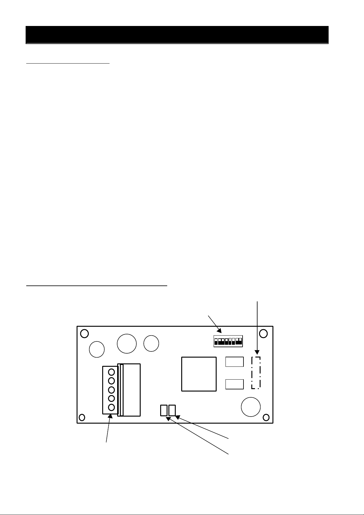
Connector for connecting to SJ300/L300P (Rear of unit)
Phoenix Contact Co, Ltd. (MSTB2.5/5-ST-5.08AU) etc
Module status LED (MOD)
DIP SW (SW) for setting MAC ID and Baud rate
1.3 Outline of product
SJ-DN is DeviceNet communication board for SJ300/L300P series inverter.
SJ-DN conforms to open field Network DeviceNet and it activates as slave function (Group 2 only server).
SJ-DN is also conforms ODVA’s certification.
(SJ-DN has been tested by ODVA's authorized Independent Test Lab and found to comply with ODVA
Conformance Test Software Version A-13.)
The following functions are available via DeviceNet communication function by installing SJ-DN to
SJ300/L300P series.
Polled Input/Output message connection
This command can exchange the master’s I/O data for the slave (Inverter) ’s I/O data.
Output data (from master to SJ-DN):
Run/Stop, reference frequency, Acceleration time, Deceleration time, Fault reset etc.
Input data (from SJ-DN to master):
Inverter status, output frequency, output current, trip history etc.
Explicit message connection
This function can reads and writes (configuration) the inverter’s parameter data, when it is necessary.
SJ-DN can use inverter below:
SJ300-004LF to 550LF, 007HF to 550HF, L300P-110LFR to 750LFR, 110HFR to 750HFR
(Note) RS485 communication function is disabled by installing SJ-DN to the inverter.
1.4 Appearance and Names of Parts
Figure 1-1 indicates the appearance of SJ-DN.
DeviceNet connector (open type)
Figure 1-1 Appearance of SJ-DN
Network status LED (NET)
2
Page 7
CHAPTER 1 INTRODUCTION
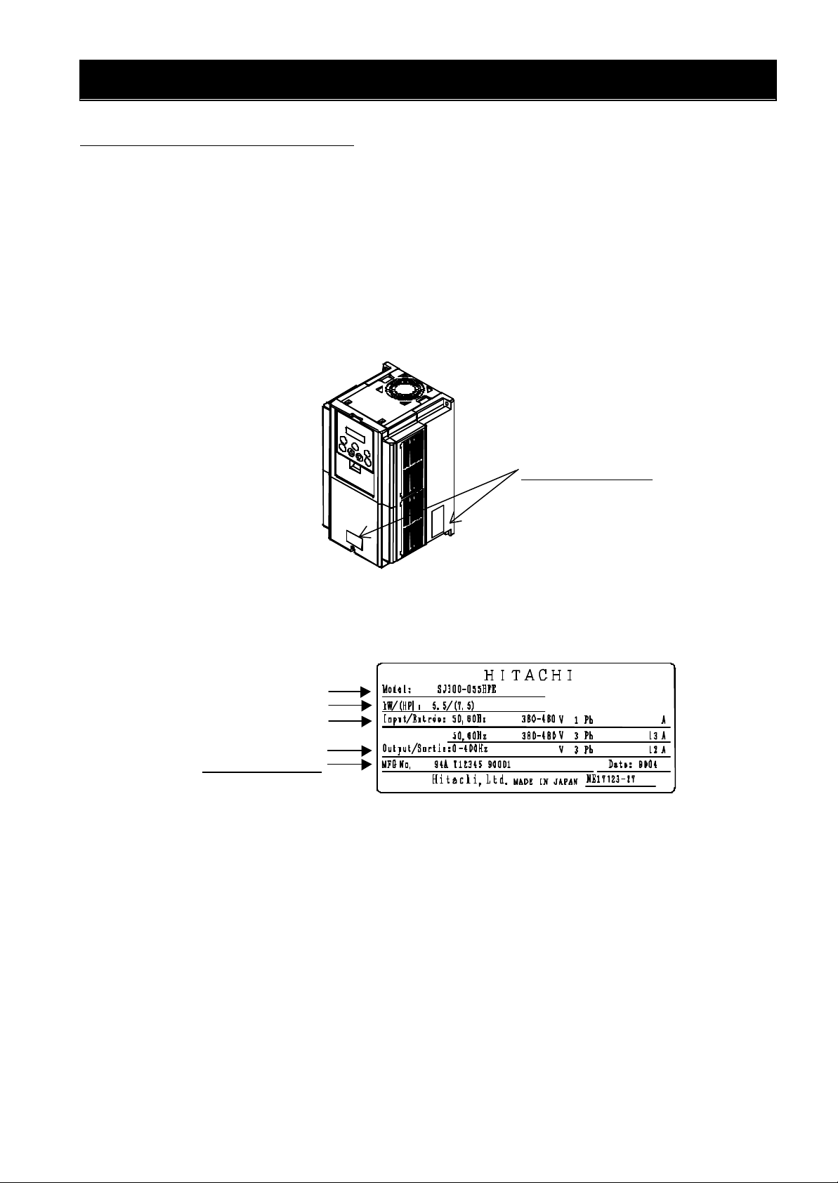
Specifications label
Inverter model
1.5 DeviceNet Support Version
SJ-DN can use following Production number(MFG No) of SJ300/L300P series.
After MFG No. : XX8KXXXXXXXXXXXX
(Note) Production number (MFG No) is written in specifications label on main body of
SJ300/L300Pseries. Refer to figure 1-2, figure 1-3.
(Figure1-2,1-3 are the example of SJ300 series. L300P series are the same manner as
SJ300 series.)
Figure 1-2 Position of specifi cations label
Maximum applicable
Output ratings
Production number
motor
Input ratings
Figure 1-3 Contents of specifications label
3
Page 8
CHAPTER 2 INSTALLATION METHOD OF PRINTED BOARD
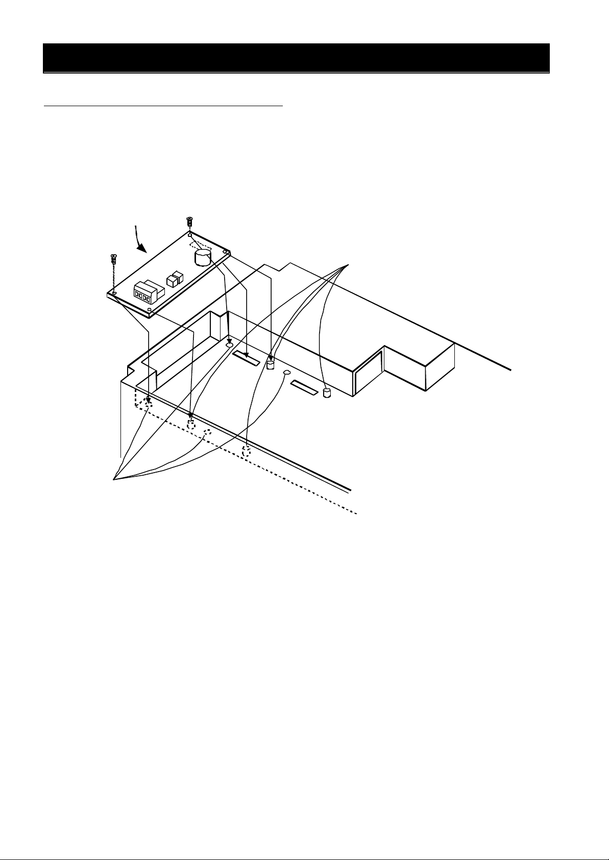
2.1 Mounting method of option board
Figure 2-1 describes how to mount the option board to the option port 1 or 2.
There are four holes on the option board, match the two of them with the screw holes on the option port 1 or 2.
and mount the other two holes with the guide posts which are located on the option port 1 and 2. To avoid
connection failure, secure the option board with screws after connection.
Option board
Guide posts for mounting the
option board.
Option port 1
Screw holes for secure option board.
(M3 Screws)
Figure 2-1 Installation of option board
Option port 2
4
Page 9
CHAPTER 3 WIRING, CONNECTING
Wiring of DeviceNet
No.
CAN_H
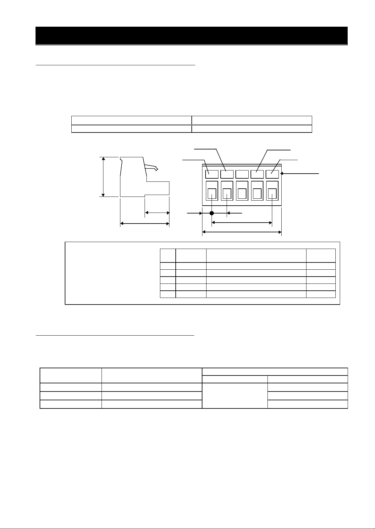
3.1 Connection for DeviceNet connector
SJ-DN has a Pluggable open connector (Male contacts), and a Network connector (Female contacts)
attached. The inverter and attach connector have a seal which is color coordinated to correspond to the
DeviceNet cable. Ensure the cable and contact are wired in the same color cable.
Cable side connector (attached connector)
Maker
Phoenix contact co, Ltd. MSTB 2.5/5ST-5.08 AU
Type
Dimension
15
18.2
Communication connector
Figure 3-1 Connector specification
Blue
Black
8.3
1 V- - (Minus) side of power supply Black
2 CAN_L Communication data (Low) Blue
3 Shield Shield Bare
4
5 V+ + (Plus) side of power supply Red
2.54
Signal
mark
5.0
20.32
25.4
Type of signal
Communication data (High) White
White
Red
Color label
Dimension in mm
Cable
color
3.2 Communication cable for DeviceNet
Use the connector which conforms to DeviceNet specification or five conductor cable and also make sure
that cable, connector and Network distance conform to DeviceNet specification.
Baud rate(kbps)
Maximum Trunk line length(m)
(Or Maximum system length(m)) Maximum length(m) Maximum total length(m)
Drop line
125 500 156
250 250 78
6
500 100
5
39
Page 10
CHAPTER 3 WIRING, CONNECTING
HITACHI
Terminating
Terminating
Power
Drop
HITACHI
3.3 Wiring note
1.Installing / removing the cable or connector must be done after checking the power supply off.
2.Wiring should not have bare cables exposed between connector contacts.
3.Network cables should be fixed without tension. Cables fixed under tension have potential of causing a
communication fault by to be removed a connector.
4.Provide a communication power source (DC24V).
5.A terminating resistor is not built-in the unit. Please provide it.
6.Ensure external emergency stop measures are taken to stop the inverter, in the event of a network fault.
(a) Remove the Power supply of the Inverter when the network master detects a communication fault.
(b) When the master detects a communication fault, turn on the intelligent input terminal which would be
allocated (FRS), (RS) and/or (EXT) function.
(c) Setting command P045 to except “02”.
In this setting, the inverter is tripped, deceleration or free run stop when it detects a communication
fault itself. (Factory initialization of command P045 is trip after deceleration stop (code: 01).)
See “4.2 Setting of the Inverter” and “4.3 Explanation of additional parameters” about explanation of
P045 (Inverter action when communication error).
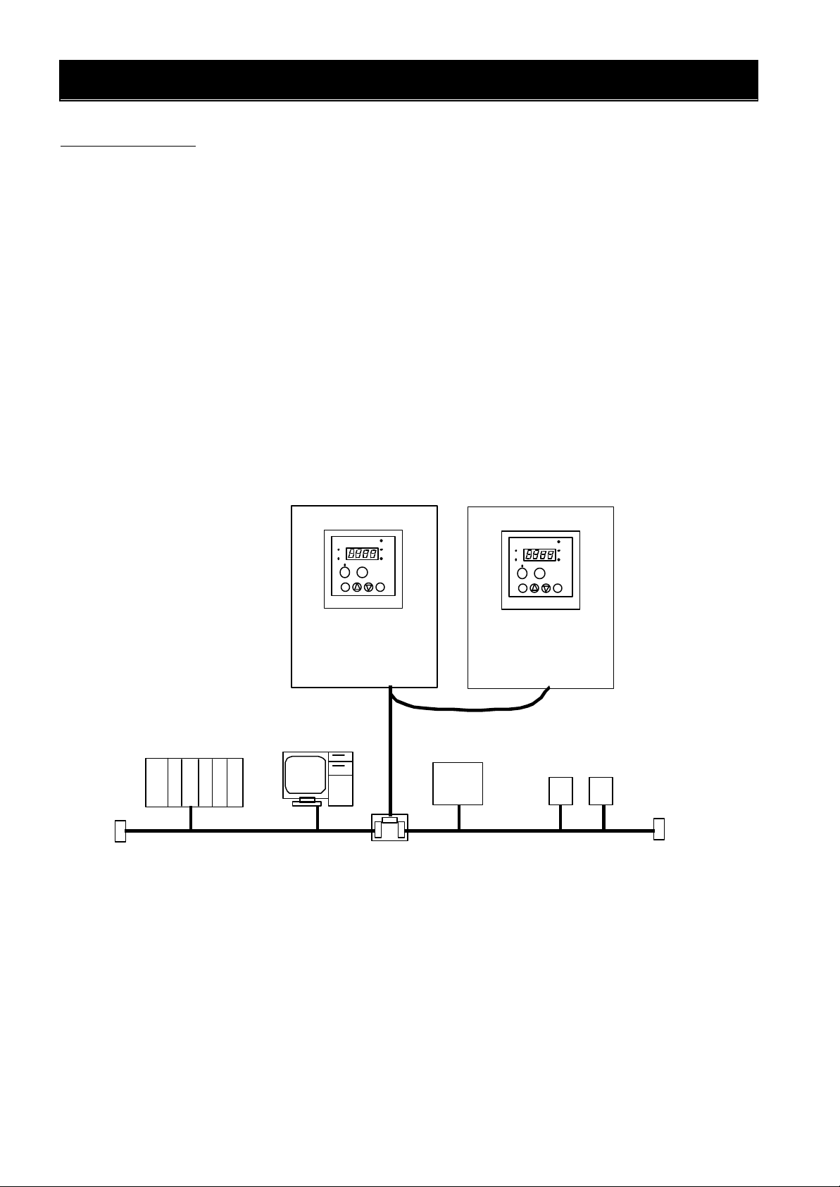
7.Basic components for construction of DeviceNet application are shown bellow.
Refer to the master ’s description manuals when DeviceNet Network system comes into operation.
DeviceNet Master UNIT
resistor(121Ω)
(PLC)
Trunk line
SJ300/L300P
Configurater (PC)
line
Multi port Tap
SJ300/L300P
Multiple Node branching drop line.
DC24V
Supply
Other slave units
Trunk line
resistor
(121Ω)
Figure 3-2 Example of components for construction of DeviceNet application
6
Page 11
CHAPTER 4 SETTING
Inverter action When
Polled I/O OUTPUT
except 0:setting and monitoring by [min-1]
↓
DR1
DR
↑
DR1
DR
↓
DR1
DRO
DR
0
MAC ID
4.1 Setting methods of Baud rate and MAC ID
Follow the procedure below to set Baud rate in DeviceNet and MAC ID, reset the power supply after
changing the setting (setting will be reflected after resetting power supply.). Initial Baud rate: 125kbps, Initial
MAC ID: 0.
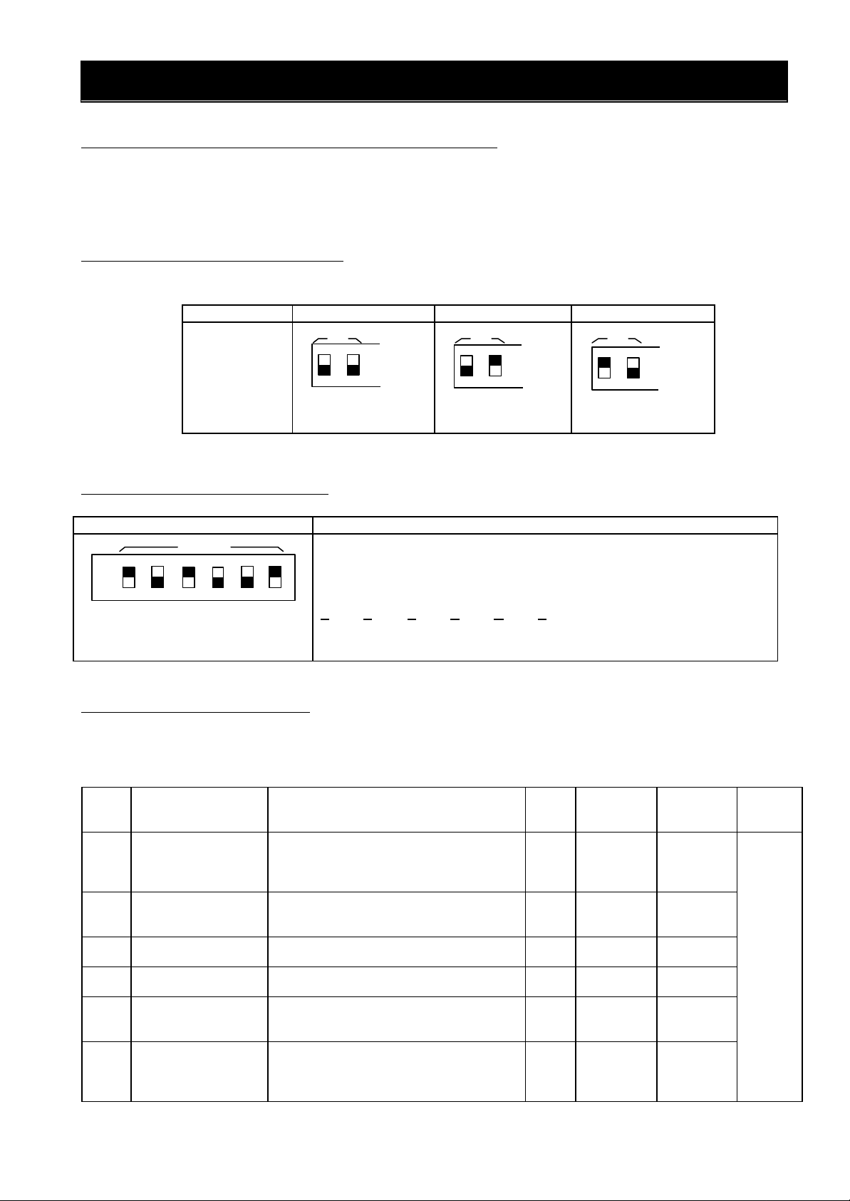
4.1.1 Setting method of Baud rate
The table below is the setting method of Baud rate (Front view of the option board.).
(↑,↓ indicate direction for switch of Dip switch )
Baud rate 125kbps 250kbps 500kbps
Dip switch
Setting
↓
DRO
ON
↓
OFF
DRO
ON
OFF
ON
↑
OFF
(Note) Do not switch on DR1 and DR0 at the same time.
4.1.2 Setting method of MAC ID
The table below is the setting method of MAC ID (Front view of the option board).
MAC ID Dip switch setting
Figure left describes the direction of Dip switches. See below.
1
NA32 NA16 NA8 NA4 NA2 NA1
Bottom: 0 Upper: 1
Bit increases from right to left switches.
Therefore, figure left becomes formula below.
1・2 +0・2 +1・2 +0・2 +0・2 +1・2 =29(Hex)=41(dec)
NA32 NA16 NA8 NA4 NA2 NA1
4
5
3 2
1
0
4.2 Setting of the Inverter
Following table describes setting items which relate SJ300 / L300P series Inverters with SJ-DN.
To set appropriate settings refer to inverter instruction manual “chapter 3 Operation”, “chapter 4 Explanation
of function” and this manual.
Code Function Range of data
P044
P045
P046
P047
P048
P049
Timer setting of
communication
timeout Whilst
running
communication
error.
Instance number
Polled I/O INPUT
Instance number
Inverter action when
Idle mode detected.
Motor poles setting
for revolutions per
minute
0.00 to 99.99(sec)
setting resolution 10nsec
Case of set to 0.00, this func. Is disable.
00(trip)/01(trip after deceleration stop)
/02(ignore)/03(free run)
/04(deceleration stop)
20,21,100 21 impossible impossible
70,71,101 71
00(trip)/01(trip after deceleration stop)
/02(ignore)/03(free run)
/04(deceleration stop)
0 to 38
Only even number is possible to set.
set to 0:setting and monitoring by [Hz ]
Initial
data
1.00 impossible impossible
Setting on
run
01 impossible impossible
impossible impossible
01 impossible impossible
0 impossible impossible
Change
mode on
run
Setting
Set data
when it
is need.
7
Page 12

CHAPTER 4 SETTING
4.3 Explanation of additional parameters
Following information provide explanation of additional parameters which are necessary to use SJ-DN.
4.3.1 P044 (Timer setting of communication timeout whilst running)
Set the allowable time that is an interval of polled I/O from DeviceNet master when the inverter is running.
When the timeout occurs, the inverter ’s behavior is as set in command P045.
4.3.2 P045 (Inverter action when communication error)
This command decides what action occurs when a communication fault is detected on the network or P044
timeout occurs at the inverter while controlled from DeviceNet.
When set to 0.00, this function is disable.
4.3.3 P046 (Polled I/O OUTPUT Instance number)
This command is instance number of assembly object Polled I/O output. Set the parameter to comply with
table below. (Combination table for P046, P047).
4.3.4 P047 (Polled I/O INPUT Instance number)
This command is instance number of assembly object Polled I/O input. Set the parameter to comply with
table below. (Combination table for P046, P047).
4.3.5 P048 (Inverter action when Idle mode detected)
This command decides what action occurs when on Idle mode is detected on the network. Inverter can start
to operate after behavior below.
At the time of set to 00, 01:After Idle mode released and fault reset, inputs stop command and run command.
At the time of set to 02 :After Idle mode released.
At the time of set to 03, 04:After Idle mode released, inputs stop command and run command.
4.3.6 P049 (Motor poles setting for revolutions per minute)
Set the Motor poles for AC Drive device profile.
0 to 38 (even number value only)
Set to 0 when frequency setting (Hz).
Set to 2 to 38 when revolution speed setting (min-1).
(Combination table for P046 and P047)
P047
70 71 101
20 ○ − −
21 − ○ −P046
100 − − ○
○:combine.
−:Do not combine.
(Note) Do not combine P046 with P047 except for combination table above, otherwise data may not be set
correctly or may not be displayed correctly.
8
Page 13
CHAPTER 5 OPERATION
OUT
Reverse
Forward
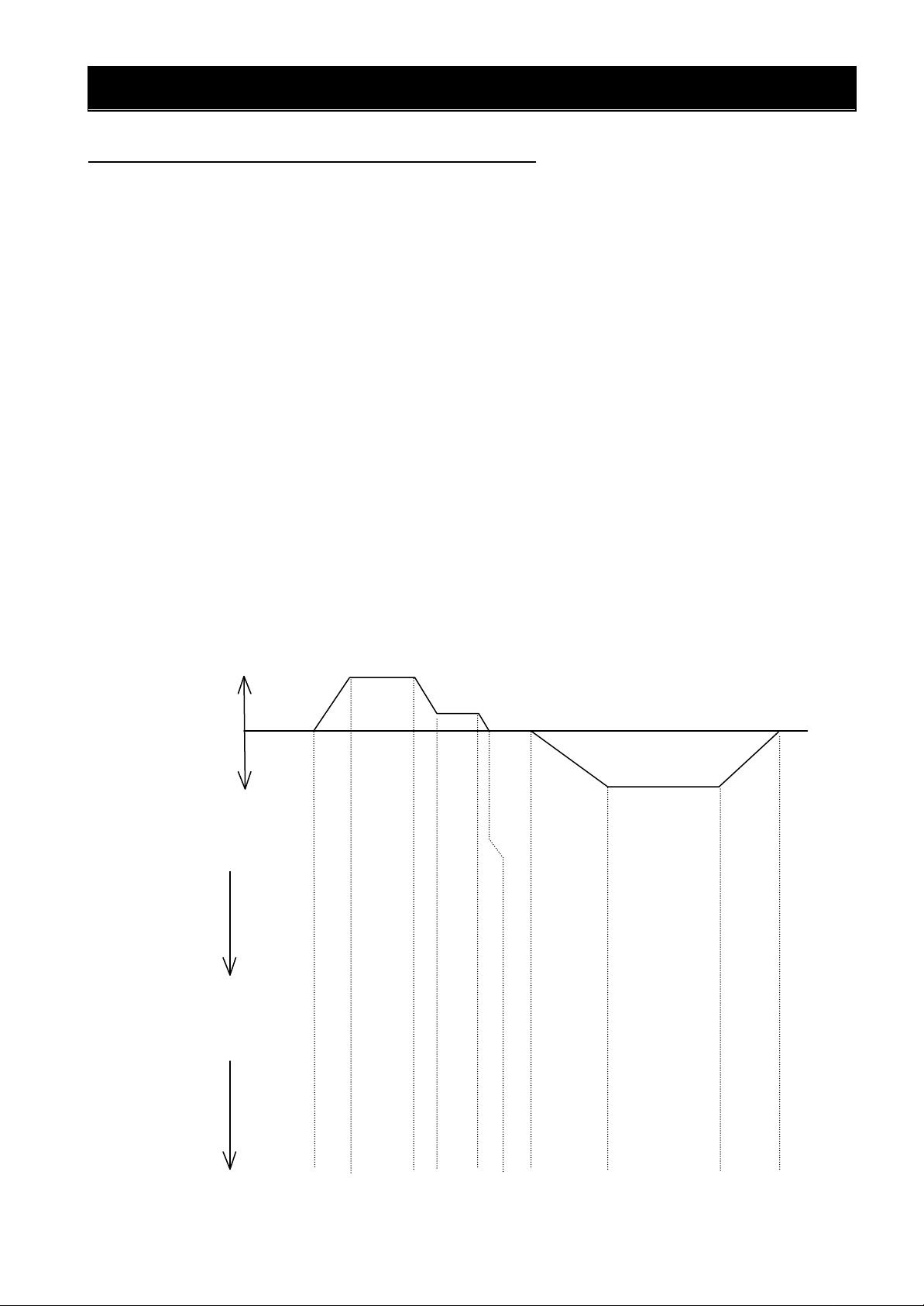
5.1 Operate with Frequency command〔Hz〕
Following information indicate the explanation of the inverter control data at P046: 100 and P047: 101.
See Chapter 6 about explanation of Polled I/O message.
Explanation on each data frame
[Output data frame]
(1) Stop command. Set frequency: 50Hz (1388hex), Acceleration: 10sec.(0064hex) and Deceleration: 10sec.
(0064hex). Both Frequency source and Run command source set from DeviceNet.
(2) Forward running command.
(3) Change frequency setting: 10Hz(03E8hex).
(4) Stop command
(5) Reverse running command. Set Frequency: 50Hz(1388hex), Acceleration: 20sec.(00C8hex) and
Deceleration: 20sec.(00C8hex).
(6) Stop command
[Input data frame]
(7) Stop condition
(8) While the inverter is in the forward run condition and accelerating, “XX” represents frequency and current.
(9) Constant speed condition. Frequency arrives at 50Hz.
(10) Deceleration condition.
(11) Constant speed condition. Frequency arrives at 10Hz.
(12) Deceleration condition.
(13) Stop condition.
(14) The inverter is in the reverse run condition and accelerating.
(15) Constant speed condition. Frequency arrives at 50Hz.
(16) Deceleration condition.
(17) Stop condition.
ACC,DEC=10sec.
50Hz
running
running
0Byte
7Byte
IN
0Byte
7Byte
60
00
88
13
64
00
64
00
00
00
00
00
00
00
00
C0
10Hz
61
00
88
13
64
00
64
00
(8)(7)
11
01
01
01
88
xx
13
xx
xx
xx
xx
xx
00
00
C0
C0
61
00
E8
03
64
00
64
00
01
01
xx
xx
xx
xx
00
C0
11
01
E8
03
xx
xx
00
C0
60
00
E8
03
64
00
64
00
01
01
xx
xx
xx
xx
00
C0
ACC,DEC=20sec.
62
00
88
13
C8
00
C8
00
02
00
01
00
xx
00
xx
00
xx
00
xx
00
00
00
C0
C0
12
01
88
13
xx
xx
00
C0
50Hz
(6)(5)(4)(3)(2)(1)
60
00
88
13
C8
00
C8
00
02
01
xx
xx
xx
xx
00
C0
(17)(16)(15)(14)(13)(12)(11)(10)(9)
00
00
00
00
00
00
00
C0
9
Page 14

CHAPTER 5 OPERATION
min
Reverse
Forward
5.2 Operate with Rotational speed command〔min-1〕
Following information indicate the example of the inverter control data at P046: 21, P047: 71 and P049: 4.
See Chapter 6 about explanation of Polled I/O message.
Explanation on each data frame.
[Output frame]
(1) Stop command. Set rotational speed:1800min-1(0708hex). Acceleration / Deceleration command are
dependant on the inverter setting. Both rotational speed and run command set from DeviceNet.
(2) Forward running command.
(3) Change rotational speed command: 600min-1 (0258hex).
(4) Stop command.
(5) Reverse running command. Set rotational speed:1800min-1 (0708hex).
(6) Stop command.
[Input frame]
(7) Stop condition
(8) While the inverter is forward run condition and accelerating, “XX” represents rotational speed.
(9) Constant speed condition. Revolutions arrive at 1800min-1.
(10) Deceleration condition.
(11) Constant speed run condition. Revolutions arrive at 600min-1.
(12) Deceleration condition.
(13) Stop condition.
(14) The inverter is in the reverse run condition and accelerating.
(15) Constant speed condition. Revolutions arrive at 1800min-1.
(16) Deceleration condition.
(17) Stop condition.
1800
-1
running
running
0Byte
3Byte
0Byte
3Byte
OUT
IN
60
00
08
07
70
03
00
00
61
00
08
07
(8)(7) (17)(16)(15)(14)(13)(12)(11)(10)(9)
F4
74
04
04
08
xx
07
xx
61
00
58
02
74
05
xx
xx
600min
F4
04
58
02
60
00
58
02
74
05
xx
xx
10
-1
-1
(6)(5)(4)(3)(2)(1)
60
00
08
07
78
05
xx
xx
70
03
00
00
70
03
00
00
62
00
08
07
78
04
xx
xx
1800min
F8
04
08
07
Page 15

CHAPTER 6 DEVICENET COMMUNICATION FUNCTION
6.1 Feature of DeviceNet communication function
SJ-DN conforms to open field Network DeviceNet and it activates as slave function (Group 2 only server).
There are two ways to communicate with the master, one is polled I/O message communication and the other
one is explicit message communication. Also SJ-DN corresponds to the AC Drive profile.
6.2 Basic DeviceNet specification
The table below describes basic DeviceNet specification of this product.
Items Specification
Protocol
Supportcommunicationspeed 125kbps(500m)/250kbps(250m)/500kbps(100m)
Maximumnumberofconnection
Node
Support connection
Datalength
Type of device
Device profile AC Drive
DeviceNet Volume I -Release2.0
DeviceNet Volume II-Release2.0
64 Nodes (Maximum number of Node for slaves are 63 Nodes)
Explicit Message
Polled Input/Output Message
Explicit Message (Each of Data has different length which are
dependant on data.)
Polled Input/Output Message 4Bytes / 8 Bytes
Group2 Only Server
(Predefined Master/Slave Connection Set)
List of object for mounting is shown below.
Name of objects Class ID Instance ID Contents
Identity 01
Message Router 02
DeviceNet 03
Connection 05
Motor Data 40
Control Supervisor 41
AC/DC Drive 42
Inverter parameter
100〜109 1,2,3
1
1
1
20,21,100
70,71,101
1,2
1
1
1
Information for distinguishing Device type, Serial
number and Vender ID etc.
This Router gives Explicit message to appropriate
object.
It controls Physical connection for DeviceNet
It controls Pol led I/O Output Message.Assembly 04
It controls Pol led I/O Input Message.
It controls Connection.
It controls the motor connected to the inverter.
It controls control information of the inverter.
It controls operational information of the inverter.
It controls inverter parameter.
See Appendix about details of Inverter parameter.
11
Page 16

CHAPTER6 DEVICENET COMMUNICATION FUNCTION
6.3 Details of Polled I/O communication
6.3.1 Basic I/O instance
This I/O instance is standard I/O instance, which is defined by AC drive profile in DeviceNet.
Master to SJ-DN: Instance20 (P046: 20)
Byte Bit7 Bit6 Bit5 Bit4 Bit3 Bit2 Bit1 Bit0
0 - - - - 1 -
2 Speed Reference (Low Byte)
3 Speed Reference (High Byte)
Data Contents
Run Fwd The inverter is running forward. 0:Stop 1:Run
Fault Reset
Speed Reference
When the bit is set to “1”, the trip states can be cancelled
0:- 1:Fault reset
It indicates speed command of the inverter.
[P049:Except for 0]
Rotational speed setting: Speed Reference(min-1) / 2 SS: Speed scale
Range of setting:0〜24000(min-1) (Resolution: 1min-1) Magnification: 1 time
e.g.) When the order of speed setting is 1800 min-1, (Speed scale:0)
Speed Reference=1800/2 =1800=0708(Hex)
[P049:0]
Operational frequency setting (Resolution: 0.01Hz ).
Range of setting:0.00 to 400.00(Hz) Magnification: 100 time
O
Fault
Reset
- Run Fwd
SS
SJ-DN to Master: Instance70 (P047 : 70)
Byte Bit7 Bit6 Bit5 Bit4 Bit3 Bit2 Bit1 Bit0
0 - - - - 1 -
2 Speed Actual (Low Byte)
3 Speed Actual (High Byte)
Data Contents
Faulted
Running 1
Speed Actual
It indicates the inverter is in a fault detecting state.
0:Normal 1:During detecting fault state
It indicates inverter’s running state.
0:Stop/During Reverse run 1:During Forward Run
It indicates inverter speed.
[P049:Except for 0]
Rotational speed monitor: Speed Actual(min-1) / 2 SS: Speed scale
Range of monitor:0〜24000(min-1) (Resolution: 1min-1) Magnification: 1 time
e.g.) When Speed Actual is 03E8(Hex) (Speed scale:0)
Speed Actual=03E8(Hex)/2 =1000/2 =1000(min-1)
[P049:0]
Current frequency display (Resolution: 0.01Hz ).
Range of monitor:0.00 to 400.00(Hz) Magnification: 100 time
O
Running
1
O
- Faulted
SS
12
Page 17

CHAPTER 6 DEVICENET COMMUNICATION FUNCTION
6.3.2 Expansive I/O Instance
This I/O instance is standard I/O instance, which is defined by AC drive profile in DeviceNet.
Master to SJ-DN: Instance21 (P046 : 21)
Byte Bit7 Bit6 Bit5 Bit4 Bit3 Bit2 Bit1 Bit0
0 - NetRef NetCtrl - 1 -
2 Speed Reference (Low Byte)
3 Speed Reference (High Byte)
Data Contents
Run Fwd The inverter is running forward. 0:Stop 1:Run forward
Run Rev The inverter is running reverse. 0:Stop 1:Run reverse
Fault Reset
NetCtrl
NetRef
Speed Reference
When the Bit is set to “1”, the trip states can be cancelled.
0:- 1:Fault reset
It indicates method of operation command.
0:Method of operation command, which is selected at operation command
selection(A002).
1:Method of Operation command from DeviceNet is valid.
It indicates method of frequency command.
0:Method of frequency command, which is selected at frequency command
selection(A001).
1:Method of frequency command from DeviceNet is valid.
It indicates speed command of the inverter.
[P049:Except for 0]
Rotational speed setting: Speed Reference(min-1) / 2 SS: Speed scale
Range of setting:0〜24000(min-1) (Resolution: 1 min-1) Magnification: 1 time
e.g.) When the order of speed setting is 1800 min-1, (Speed scale:0)
Speed Reference=1800/2 =1800=0708(Hex)
[P049:0]
Operational frequency setting (Resolution: 0.01Hz).
Range of setting:0.00 to 400.00(Hz) Magnification: 100 time
O
Fault
Reset
Run Rev Run Fwd
SS
(Note) When set both Run Fwd and Run Rev to 1, the inverter executes the command, which is inputted first.
13
Page 18

CHAPTER6 DEVICENET COMMUNICATION FUNCTION
SJ-DN to Master: Instance71 (P047 : 71)
Byte Bit7 Bit6 Bit5 Bit4 Bit3 Bit2 Bit1 Bit0
0
1 Drive Status
2 Speed Actual (Low Byte)
3 Speed Actual (High Byte)
Faulted
Warning
Running1(Fwd)
Running2(Rev)
Ready
Ctrl From Net
Ref From Net
At Reference
Drive Status
Speed Actual
At
Reference
Data Contents
Ref From
Net
It indicates the inverter is in a fault detecting state.
0:Normal 1:During detecting fault state
It indicates the inverter is in a warning detecting state.
0:Normal
1:During detecting warning (When there is contradiction on the inverter setting.).
It indicates inverter’s running condition.
0:Stop / During reverse run 1:During forward run
It indicates inverter’s running condition.
0:Stop / During forward run 1:During reverse run
It indicates the inverter ready for drive.
0:Except Drive status: 3,4,5.
1:Complete ready to drive (Drive Status: 3,4,5).
It indicates selection state for inputting the inverter operational command
0:Operation command selection(A002) is valid to set.
1:Operation command from DeviceNet is valid.
It indicates selection state for inputting the inverter frequency command.
0:Frequency command selection(A001) is valid to set.
1:Frequency command from DeviceNet is valid.
It indicates arrival frequency detecting state for the inverter.
0:During stop / During accelerate or decelerate
1:Arrival frequency
It indicates inverter status.
1:Startup (Only R0-T0 power supply is ON)
2:Not Ready (Just after turn on power supply)
3:Ready (Able to activate the inverter )
4:Enabled (Inverter is running by run command)
5:Stopping (Inverter is decelerating by stop command)
6:Fault Stop (Inverter is decelerating because trip is detected)
7:Faulted (Trip condition)
It shows inverter speed.
[P49:Except for 0]
Rotational speed monitor: Speed Actual(min-1) / 2 SS: Speed scale
Range of monitor:0〜24000(min-1) (Resolution: 1min-1) Magnification: 1 time
e.g.) When Speed Actual is 03E8(Hex) (Speed scale:0)
Speed Actual=03E8(Hex)/2 =1000/2 =1000(min-1)
[P049:0]
Current frequency display (Resolution: 0.01Hz ).
Range of monitor:0.00 to 400.00(Hz) Magnification: 100 time
Ctrl From
Net
Ready
Running2
(Rev)
O O
Running1
(Fwd)
SS
Warning Faulted
14
Page 19

CHAPTER 6 DEVICENET COMMUNICATION FUNCTION
6.3.3 Hitachi inverter I/O Instance
This I/O instance is able to control the operation control, which is necessary to Hitachi inverters.
Master to SJ-DN: Instance100 (P046: 100
Byte Bit7 Bit6 Bit5 Bit4 Bit3 Bit2 Bit1 Bit0
0 − NetRef NetCtrl −
1 −
2 Speed Reference (Low Byte)
3 Speed Reference (High Byte)
4 Acceleration time (Low Byte)
5 Acceleration time (High Byte)
6 Deceleration time (Low Byte)
7 Deceleration time (High Byte)
Data Contents
Run Fwd The inverter is running forward run. 0:Stop 1:Run forward
Run Rev The inverter is running reverse run. 0:Stop 1:Run reverse
When the Bit is set to “1”, the trip states can be cancelled.
Fault Reset
Free run stop
NetCtrl
NetRef
Speed Reference
Acceleration time /
Deceleration time
(Note) When set both Run Fwd and Run Rev to 1, the inverter executes as stop command.
0:- 1:Fault reset
Case of the inverter is not in trip condition, when the Bit is set to “1”, the inverter
will stop the motor.
When the Bit is set to “1”, the inverter stops output and the motor enters the free
run mode.
0:- 1:Free run stop
It indicates setting for method of operational command.
0:Method of operation command, which is selected at operation command
selection (A002).
1:Method of Operation command from DeviceNet is valid.
It indicates setting for method of frequency command.
0:Method of Frequency command, which is selected at frequency command
selection(A001) and setting at Acc / Dec time(F002, F003).
1:Method of frequency and Acc / Dec time command from DeviceNet is valid.
It indicates setting for output frequency of the inverter.
Range of setting:0.00 to 400.00(Hz), Resolution: 0.01(Hz), Magnification:100
times, Transmit data:0 to 9C4O(Hex)
It indicates setting for Acc/Dec time of the inverter.
Range of setting:0.1 to 3600.0(sec), Resolution:0.1(sec), Magnification:10 times
Transmit data:1 to 8CA0(Hex)
If Acceleration / Deceleration time has not been set by DeviceNet, the inverter will
use the settings in command F002 / F003.
)
Free run
stop
Fault
Reset
Run Rev Run Fwd
15
Page 20

CHAPTER6 DEVICENET COMMUNICATION FUNCTION
SJ-DN to Master: Instance101 (P047: 101)
Byte Bit7 Bit6 Bit5 Bit4 Bit3 Bit2 Bit1 Bit0
Input
Terminal
0
3 State
1 Drive Status
2 Speed Actual (Low Byte)
3 Speed Actual (High Byte)
4 Output current (Low Byte)
5 Output current (High Byte)
6 Trip cause
Ref From
7
Running1(Fwd)
Running2(Rev)
Faulted
At Reference
Input Terminal 1 State 0: (opened) 1: Input terminal 1 and common are closed.
Input Terminal 2 State 0: (opened) 1: Input terminal 2 and common are closed.
Input Terminal 3 State 0: (opened) 1: Input terminal 3 and common are closed.
Input Terminal 4 State 0: (opened) 1: Input terminal 4 and common are closed.
Input Terminal 5 State 0: (opened) 1: Input terminal 5 and common are closed.
Input Terminal 6 State 0: (opened) 1: Input terminal 6 and common are closed.
Input Terminal 7 State 0: (opened) 1: Input terminal 7 and common are closed.
Input Terminal 8 State 0: (opened) 1: Input terminal 8 and common are closed.
Forward Terminal State 0: (opened) 1: Forward terminal (FW) and common are closed.
Drive Status
Speed Actual
Net
Data Contents
Input
Terminal
2 State
Ctrl From
Net
It indicates inverter’s running condition.
0:Stop / During reverse run 1:During forward run
It indicates inverter’s running condition.
0:Stop / During forward run 1:During reverse run
It indicates the inverter is in a fault detecting state.
0:Normal 1:During detecting fault state
It indicates arrival frequency detecting state for the inverter.
0:During stop / During accelerate or decelerate
1:Arrival frequency
It indicates the inverter condition.
00:The inverter is stopping.
01:The inverter is running.
02:The inverter is in jogging mode.
03:The inverter’s output is stopped and the motor is free running (coasting).
04:The inverter is executing DC braking.
This includes the DC braking wait time.
05:The inverter is trying to restart with frequency matching.
Command b001 is set to ”3”.
06:Stop output at instantaneous power failure.
07:The inverter is trying to restart with frequency matching.
Command b001 is set to “2”.
08:The inverter is waiting before it runs on motor again to restart with
frequency matching (by setting b001, b088, C103).
This waiting time is as setting value command b003.
10:The inverter is in a trip condition.
11:The inverter is in under-voltage condition.
It indicates the inverter’s output frequency monitor.
Monitor range:0.00 to 400.00(Hz), Resolution: 0.01(Hz), Magnification:100
times, Receiving data:0 to 9C4O(Hex)
Input
Terminal
1 State
Forward
Terminal
state
At
Reference
Input
Terminal
8 State
− Faulted
Input
Terminal
7 State
Terminal
Input
6 State
Running2
(Rev)
Input
Terminal
5 State
Running1
(Fwd)
Input
Terminal
4 State
16
Page 21

Data Contents
Output current
Trip cause
Ctrl From Net
Ref From Net
CHAPTER 6 DEVICENET COMMUNICATION FUNCTION
It indicates the inverter’s output current monitor.
Monitor range:0 to 6553.5A, Magnification:10 times, Receiving data:0 to
FFFF(Hex)
Following codes are latest trip history.
00:No trip
01:Over current protection (at constant speed)
02:Over current protection (at deceleration)
03:Over current protection (at acceleration)
04:Over current protection (at the other)
05:Over load protection
06:Dynamic break resistor protection
07:Over voltage protection
08:EEPROM error
09:Under voltage
10:CT error
11:CPU error
12:External trip
13:USP error
14:Ground fault protection
15:Input over voltage protection
16:Instantaneous power failure protection
21:Abnormal temperature
23:Gate array error
24:Phase-failure
30:IGBT error
35:Thermistor error
36:Abnormal break
60 to 69:Option error 1
70 to 79:Option error 2
It indicates selection state for inputting the inverter operational command
0:Operation command selection(A002) is valid to set.
1:Operation command from DeviceNet is valid.
It indicates selection state for inputting the inverter frequency command.
0:Frequency command selection(A001), Aceeleration time setting (F002) and
Deceration time setting (F003) are valid to set.
1:Frequency command from DeviceNet is valid.
17
Page 22

CHAPTER6 DEVICENET COMMUNICATION FUNCTION
Communication
ID
Type of data
ID
Type of data
6.4 Detail of DeviceNet profile
6.4.1 Overall Specification
General
Device data
Physical Network power consumption 50mA
Conformance Type of connector Open connector
Data Isolated physical layer Yes
Data
6.4.2 Identity Object (ID=1 Hex)
Instance0 Not supported ― ― ― ―
Instance1 Vender ID 1 Get UINT 74 AC Drive
Support service (Common service)
Get_Attribute_Single H’0E
Reset H’05 00:Reset
NOP H’17
DeviceNet specification Volume I -Release2.0
Vender name Hitachi, Ltd. Vender ID=74
DeviceNet profile name Slave AC Drive Profile No=2
Product Catalog NO.
Product revision 1.1
Operation power source DC11V to 24V
Support LED Module status, Network status
Setting of MAC ID Set at Dip SW.
Default MAC ID 0
Communication Baud rate setting Set at Dip SW.
Communication Baud rate supported 125kbps/250kbps/500kbps
Device Network behavior Group 2 only server
UCMM support No
Support connection Explicit Message
Fragmented Explicit messaging Supported Yes
Attribute ID Access rule Type of data Initial data
Device Type 2 Get UINT 2
Product Code 3 Get UINT 0703(Hex)
Revision Major 4 Get USINT 1
Minor USINT 1
Status 5 Get WORD 0
Serial Number 6 Get UDINT Factory initial
Product Name 7 Get STRING “SJ-DN”
Service Service code Note
01:User initialize with History clear
Volume II-Release2.0
− −
Polled Input/Output Message
6.4.3 DeviceNet Object (ID=3 Hex)
Attribute
Instance0 Revision 1 Get UINT 2
Instance1 MAC ID 1 Get/Set USITT Set at Dip SW.
Baud Rate 2 Get/Set USINT Set at Dip SW.
BOI 3 Get BOOL 0
BusOff Counter 4 Get/Set USINT 0
Allocation Information Choice Byte 5 Get BYTE Masters MAC ID
Supported service
Service name Code Remarks
Get_Attribute_Single H’0E
Set_Attribute_Single H’10
Allocate_M/S_Connection_Set H’4B
Release_M/S_Connection_Set H’4C
Access rule
USINT -
6.4.4 Assembly Object (ID=4 Hex)
Attribute
Instance0 Not supported - - - Instance20 DATA 3 Get/Set 4 Bytes Instance21 DATA 3 Get/Set 4 Bytes Instance70 DATA 3 Get 4 Bytes Instance71 DATA 3 Get 4 Bytes Instance100 DATA 3 Get/Set 8 Bytes Instance101 DATA 3 Get 8 Bytes -
Access rule
18
Initial data
Initial data
Page 23

ID
13
14
15
16
16
Supported service
Service name Code Remarks
Get_Attribute_Single H’0E
Set_Attribute_Single H’10
CHAPTER 6 DEVICENET COMMUNICATION FUNCTION
6.4.5 Connection Object (ID=5 Hex)
Attribute
Instance0 Not supported - - - Instance1 state 1 Get USINT -
instance_type 2 Get USINT 00
transportClass_triger 3 Get BYTE H’83
prod_conn_id 4 Get UINT coms_conn_id 5 Get UINT initial_comm_characteristice 6 Get BYTE H’21
prod_conn_size 7 Get UINT H’24
coms_conn_size 8 Get UINT H’24
expected_packet_rate 9 Get/Set UINT H’09C4
watchdog_timeout_action 12 Get USINT 1
prod_conn_path_length
prod_conn_path
coms_conn_path_length
coms_conn_path
Instance2 state 1 Get USINT -
instance_type 2 Get USINT 01
transportClass_triger 3 Get BYTE H’82
prod_conn_id 4 Get UINT coms_conn_id 5 Get UINT initial_comm_characteristice 6 Get BYTE 01
prod_conn_size 7 Get/Set UINT H’08
coms_conn_size 8 Get UINT H’08
expected_packet_rate 9 Get/Set UINT 0
watchdog_timeout_action 12 Get USINT 0
prod_conn_path_length 13 Get UINT 3
prod_conn_path 14 Get UINT order H’623635
coms_conn_path_length 15 Get UINT 3
coms_conn_path
Access rule Data type Initial data
Get UINT 0
Get UINT order Get UINT 0
Get UINT order -
Get UINT order H’623634
Supported service
Reset H’05
Get_Attribute_Single H’0E
Set_Attribute_Single H’10
Service name Code Remarks
6.4.6 Motor Date Object (ID=28 Hex)
Attribute ID Access rule Data type Initial data
Instance0 Revision 1 Get WORD 0001
Instance1 MotorType 3 Get BYTE 07
Supported service
Get_Attribute_Single H’0E
Set_Attribute_Single H’10
RatedCurrent 6 Get/Set WORD b012 setting
RatedVoltage 7 Get/Set WORD A082 setting
PoleCount 12 Get/Set WORD P049 setting
Service name Code Remarks
19
Page 24

CHAPTER6 DEVICENET COMMUNICATION FUNCTION
10
11
12
13
15
16
17
18
6.4.7 Control Supervisor Object (ID=29 Hex)
Attribute ID Access rule Data type Initial data
Instance0 Revision 1 Get WORD 0001
Instance1 Run1 3 Get/Set BYTE 00
Run2 4 Get/Set BYTE 00
NetCtrl 5 Get/Set BYTE 00
State 6 Get BYTE 01
Running1 7 Get BYTE 00
Running2 8 Get BYTE 00
Ready 9 Get BYTE 00
Faulted
Warning
FaultRst
FaultCode
CtrlFromNet
DNFaultMode
ForceFautl/Trip
ForceStatus
Get BYTE 00
Get BYTE 00
Get/Set BYTE 00
Get WORD 0000
Get BYTE 00
Get BYTE 02
Get/Set BYTE 00
Get BYTE 00
Supported service
Get_Attribute_Single H’0E
Set_Attribute_Single H’10
Service name Code Remarks
6.4.8 AC/DC Drive Object (ID=2A Hex)
Attribute ID Access rule Data type Initial data
Instance0 Revision 1 Get WORD 0001
Instance1 AtReference 3 Get BYTE 00
NetRef 4 Get/Set BYTE 00
NetCtrl 5 Get BYTE 00
DriveMode 6 Get BYTE 01
SpeedActual 7 Get WORD 0001
SpeedRef 8 Get/Set WORD F001 setting
CurrentActual 9 Get WORD 0000
CurrentLimit 10 Get/Set WORD 0000
TorqueActual 11 Get WORD 0000
PowerActual 15 Get WORD 0000
InputVoltage 16 Get WORD 0000
OutputVoltage 17 Get WORD 0000
AccelTime 18 Get/Set WORD F002 setting
DecelTime 19 Get/Set WORD F003 setting
LowSpdLimit 20 Get/Set WORD A062 setting
HightSpdLimit 21 Get/Set WORD A004 setting
SpeedScale 22 Get/Set BYTE 0
CurrentScale 23 Get/Set BYTE 0
TorqueScale 24 Get/Set BYTE 0
PowerScale 26 Get/Set BYTE 0
VoltageScale 27 Get/Set BYTE 0
TimeScale 28 Get/Set BYTE 0
RefFromNet 29 Get BYTE 00
Supported service
Servicxe name Code Remaraks
Get_Attribute_Single H’0E
Set_Attribute_Single H’10
20
Page 25

CHAPTER 7 COUNTERMEASURE FOR ABNORMALITY
29Hex, Instance: 1 and Attribute:
Trip code
7.1 Trip display
When the inverter is in a tripped state, the inverter displays an error code (See table below). The trip history
monitor (d081 to d086) also displays the same error code as the inverter.
Inverter’s running condition of trip detected
7.2 Protection function list
The table below describes an error code for protecting the inverter and the motor.
Error Display in the table below, X is 6 (Error for option slot 1) or 7 (Error for option slot 2).
No. Function Error
Display
1 DeviceNet
EX0 This error is displayed, disconnection occurs when BusOff or
communication error
2 Duplicate MACID EX1 This error indicates that component have the same MADID,
3 External trip EX2 This error is displayed, when Fault / Trip is set to 1 toward
4 Inverter communication
EX9 This error is displayed, when communication timeout occurs
error
With regard to the other errors except table above, refer to Inverter instruction manual chapter 4 Explanation
of function.
Action
timeout is occurred, while the inverter is operating with
DeviceNet. (Trip is caused by P045 and P048 setting)
which exist on the same network.
control supervisor object data: Instance 1, Attribute 17.
between the inverter and the option board.
7.3 Countermeasure for a trip state
The table below only corresponds to additional trip codes, with regard to the other countermeasures refer to
Inverter instruction manual chapter 4 Explanation of function.
Trip
code
EX0 DeviceNet
EX1 Duplicate
EX2 External
EX9 Inverter
Name of trip Cause Conformation Countermeasure
Communication
error
MACID
Trip
communication
error
Baud rate is different. Check Baud
rate
Wiring distance does not
match with Baud rate
Defective connector for
signal cable causes
connection fail.
Terminating resistor is
not connected.
Network power supply is
not connected. Network
power supply is out of
regulation.
Exceeding maximum
Node.
Components have the
same MACID, which are
connected on the same
network.
Class : 29Hex
Instance: 1
Attribute: 17
Option board is
removed.
Check the wiring
distance
Check the area of
connection.
Check the
Connection
Check the
Network power
Supply voltage
(DC11 to 24V)
Check the Node. Remove unnecessary components
Check the all MACID
and also check the
component which has
the same MACID
Check as mentioned left. Set Fault/ trip to 0 toward class:
Check as mentioned left Mount the option board again and
Install correct Baud rate and then
reset the power supply.
Adjust the setting to the matching
Baud rate.
Adjust Wiring distance.
Improve the connection and then
reset the power supply.
Connect the terminating
Resistor and then reset the power
supply
Connect Network power supply and
then reset the power supply.
and adjust Node to 64 (Maximum)
or under, then reset the power
supply.
Set MACID and then reset the
power supply.
17.
then secure it with screws.
21
Page 26

CHAPTER 7 COUNTERMEASURE FOR ABNORMALITY
possible to restore. Mostly this state
7.4 LED display and Countermeasure
Following states are indicated by module LED and Network LED.
MOD (Module status) LED: It indicates Inverter condition.
NET (Network status) LED: It indicates Network condition.
LED Color Explanation Countermeasure
MOD Green lamp
is ON
Green lamp
goes ON
and OFF
Red lamp
is ON
Red lamp
goes ON
and OFF.
OFF Power off
NET Green lamp
is ON
Green lamp
goes ON
and OFF
Red lamp
is ON
Red lamp
goes ON
and OFF.
OFF Power off / DeviceNet offline
The inverter is in normal condition
The inverter is in standby condition.
An abnormality occurred which is
impossible to restore.
But except status below.
User initializing with b084 set to 01, 02.
An abnormality occurred which is
occurs, when the inverter is in trip
conditi on.
But except status below.
User initializing with b084 set to 01, 02.
Online state and Connection are
established.
Online state and Connection are not
established.
Network abnormality
(Duplicate MACID, Detect BusOff etc.)
Timeout communication Check the followings
Need to fix the inverter.
Refer to inverter instruction manual.
Check the followings
Duplicate MACID.
Communication speed.
Cable disconnection.
Connection’s fail for connector.
Connection for terminating resistor.
Length of cable
Communication speed.
Cable disconnection.
Connection’s fail for connector.
Connection for terminating resistor.
Length of cable.
−
−
−
−
−
−
7.5 Other notes
When SJ-DN is installed and the Inverter ’s setting is below, the inverter will be reset to fault status when it
occur trip while driving from DeviceNet command.
Case of the inverter drive again, set run command again after release run command.
Operating mode select(A002) setting: 02(Remort)
22
Page 27

APPENDIX PARAMETER OBJECT LISTS
mand
Bit6 : Dig input 7 Bit5 : Dig input 6
Bit4 : Dig input 5 Bit3 : Dig input 4
Bit2 : Dig input 3 Bit1 : Dig input 2
110
d007
111
d012
112
d013
121
d080
123
d081
124
d081
125
d081
126
d081
127
d081
130
d082
131
d082
132
d082
133
d082
135
d083
136
d083
141
d084
142
d084
(1) Inverter Data monitor/Basic Data Setting object. Class ID=100
Function Inst Attr Size Monitoring/Setting Range
Inverter Mode (Param16) 1 100 1 00(SJ300)/01(L300P)/02(SJH300) 1 Get -
Rated Power (Param14) 1 101 1
Rated Voltage (Param15) 1 102 1
Output Frequency (Param1) 1 104 4 0.00 to 400.00(Hz) 100 Get d001
Output Current (Param2) 1 105 2 0.0 to 999.9(A) 10 Get d002
Direction (Param3) 1 106 1
PID Feedback (Param4) 1 107 4 0.00 to 999.00(%) 100 Get d004
00(0.20)/02(0.40)/04(0.75)/
06(1.50)/07(2.20)/09(3.70)/
11(5.50)/12(7.50)/13(11.0)/
14(15.0)/15(18.5)/16(22.0)/
17(30.0)/18(37.0)/19(45.0)/
20(55.0)/21(75.0)
00(200V Class)/01(400V Class)/
02(600V Class)
01(Forward)/00(Stopped)/
02(Reverse)
Bit8 : Forward Bit7 : Dig input 8
Magnifi-
cation
1 Get -
1 Get -
1 Get d003
Access
rule
Com-
Dig In Status (Param5) 1 108 2
Dig Out Status (Param6) 1 109 2
Freq-conversion (Param7) 1
Torque (Param8) 1
Output Voltage (Param9) 1
Input Elect- Pow (Param10) 1 113 2 0.0 to 999.9(kW) 10 Get d014
Elapsed Run time (Param11) 1 115 4 0 to 999999(hr) 1 Get d016
Power ON time (Param12) 1 116 4 0 to 999999(hr) 1 Get d017
DC Voltage (Param13) 1 118 2 0.0 to 999.9(V) 10 Get -
Trip Count (Param17) 1
Trip 1 Cause (Param18) 1 122 4
Trip 1 frequency (Param19) 1
Trip 1 Current (Param20) 1
Trip 1 DC Voltage (Param21) 1
Trip 1 RUN time (Param22) 1
Trip 1 P-ON time (Param23) 1
Trip 2 Cause (Param24) 1 128 4
Trip 2 frequency (Param25) 1 129 4 0.00 to 400.00(Hz) 100 Get d082
Trip 2 Current (Param26) 1
Trip 2 DC Voltage (Param27) 1
Trip 2 RUN time (Param28) 1
Trip 2 P-ON time (Param29) 1
Trip 3 Cause (Param30) 1 134 4
Trip 3 frequency (Param31) 1
Trip 3 Current (Param32) 1
Trip 3 DC Voltage (Param33) 1 137 2 0.0 to 600.0(V) 10 Get d083
Trip 3 RUN time (Param34) 2 138 4 0 to 999999(hr) 1 Get d083
Trip 3 P-ON time (Param35) 1 139 4 0 to 999999(hr) 1 Get d083
Trip 4 Cause (Param36) 2 140 4
Trip 4 frequency (Param37) 1
Trip 4 Current (Param38) 1
4 0.00 to 3996.00 100 Get
2 -300 to +300(%) 1 Get
2 0.0 to 600.0(V) 10 Get
2 0 to 65530 1 Get
4 0.00 to 400.00(Hz) 100 Get
2 0.0 to 999.9(A) 10 Get
2 0.0 to 600.0(V) 10 Get
4 0 to 999999(hr) 1 Get
4 0 to 999999(hr) 1 Get
2 0.0 to 999.9(A) 10 Get
2 0.0 to 600.0(V) 10 Get
4 0 to 999999(hr) 1 Get
4 0 to 999999(hr) 1 Get
4 0.00 to 400.00(Hz) 100 Get
2 0.0 to 999.9(A) 10 Get
4 0.00 to 400.00(Hz) 100 Get
2 0.0 to 999.9(A) 10 Get
Bit0 : Dig input 1
Close: 1, Open : 0
Bit5 : Alarm
Bit4 : Dig output 15
Bit3 : Dig output 14
Bit2 : Dig output 13
Bit1 : Dig output 12
Bit0 : Dig output 11
Close: 1, Open : 0
E01.X to E79.X (E??:Trip cause,
X:running condition)
See 6.3.3 Hitachi inverter I/O
Instance(Instance 101)
E01.X to E79.X (E??:Trip cause,
X:running condition)
See 6.3.3 Hitachi inverter I/O
Instance(Instance 101)
E01.X to E79.X (E??:Trip cause,
X:running condition)
See 6.3.3 Hitachi inverter I/O
Instance(Instance 101)
E01.X to E79.X (E??:Trip cause,
X:running condition)
See 6.3.3 Hitachi inverter I/O
Instance(Instance 101)
1 Get d005
1 Get d006
1 Get d081
1 Get d082
1 Get d083
1 Get d084
23
Page 28

APPENDIX PARAMETER OBJECT LISTS
Magnifi-
Access
Com-
mand
147
d085
148
d085
149
d085
150
d085
151
d085
155
d086
156
d086
157
d086
159
Get/Set
F001
160
Get/Set
F002
161
Get/Set
F303
162
Get/Set
F004
Magnifi-
Access
Com-
mand
103
Get/Set
A003
2nd Base Frequency (Param334)
103
Get/Set
A203
3rd Base Frequency (Param371)
103
Get/Set
A303
104
Get/Set
A004
104
Get/Set
A204
3rd Max Frequency (Param370)
104
Get/Set
A304
Function Inst Attr Size Monitoring/Setting Range
Trip 4 DC Voltage (Param39) 1 143 2 0.0 to 600.0(V) 10 Get d084
Trip 4 RUN time (Param40) 1 144 4 0 to 999999(hr) 1 Get d084
Trip 4 P-ON time (Param41) 1 145 4 0 to 999999(hr) 1 Get d084
Trip 5 Cause (Param42) 1 146 4
Trip 5 frequency (Param43) 1
Trip 5 Current (Param44) 1
Trip 5 DC Voltage (Param45) 1
Trip 5 RUN time (Param46) 1
Trip 5 P-ON time (Param47) 1
Trip 6 Cause (Param48) 1 152 4
Trip 6 frequency (Param49) 1 153 4 0.00 to 400.00(Hz) 100 Get d086
Trip 6 Current (Param50) 1 154 2 0.0 to 999.9(A) 10 Get d086
Trip 6 DC Voltage (Param51) 1
Trip 6 RUN time (Param52) 1
Trip 6 P-ON time 6(Param53) 1
Warning Monitor (Param54) 1 158 1
Frequency Setting (Param60) 1
Accel Time 1 (Param61) 1
2nd Accel Time 1 (Param337) 2 160 4 0.01 to 3600.00(s) 100 Get/Set F202
3rd Accel Time 1 (Param372) 3 160 4 0.01 to 3600.00(s) 100 Get/Set F302
Decel Time 1(Param62) 1 161 4 0.01 to 3600.00(s) 100 Get/Set F003
2nd Decel Time 1(Param338) 2 161 4 0.01 to 3600.00(s) 100 Get/Set F203
3rd Decel Time 1 (Param373) 3
Direction Setting (Param63) 1
E01.X to E79.X (E??:Trip cause,
X:running condition)
See 6.3.3 Hitachi inverter I/O
Instance(Instance 101)
4 0.00 to 400.00(Hz) 100 Get
2 0.0 to 999.9(A) 10 Get
2 0.0 to 600.0(V) 10 Get
4 0 to 999999(hr) 1 Get
4 0 to 999999(hr) 1 Get
E01.X to E79.X (E??:Trip cause,
X:running condition)
See 6.3.3 Hitachi inverter I/O
Instance(Instance 101)
2 0.0 to 600.0(V) 10 Get
4 0 to 999999(hr) 1 Get
4 0 to 999999(hr) 1 Get
00(No Warning)
01(W001) 02(W002) 03(W004)
04(W005) 05(W006) 06(W009)
07(W201) 08(W202) 09(W204)
10(W205) 11(W206) 12(W209)
13(W304) 14(W305) 15(W306)
16(W309) 17(W012) 18(W015)
19(W016) 20(W019) 21(W212)
22(W215) 23(W216) 24(W219)
25(W021) 26(W025) 27(W026)
28(W029) 29(W221) 30(W225)
31(W226) 32(W229) 33(W031)
34(W231) 35(W032) 36(W232)
37(W035) 38(W235) 39(W335)
40(W036) 41(W037) 42(W085)
43(W285) 44(W385) 45(W086)
46(W091) 47(W291) 48(W092)
49(W292) 50(W095) 51(W295)
52(W395) 53(W096) 54(W110)
55(W120)
4 0.00 to 400.00(Hz) 100
4 0.01 to 3600.00(s) 100
4 0.01 to 3600.00(s) 100
1 00(Forward)/01(Reverse) 1
cation
1 Get d085
1 Get d086
1 Get d090
rule
Support service
Service name Code
Get_Attribute_Single H’0E
Set_Attribute_Single H’10
(2) Extend Group A object Class ID=101
Function Inst Attr Size Monitoring/Setting Range
Freq-Setting Sel (Param64) 1 101 1
Operating Mode Sel (Param65) 1 102 1
Base Frequency (Param56) 1
Max Frequency (Param55) 1
2ndMaxFrequency (Param333) 2
cation
00(Volume)/01(Terminal)/
02(Operator)/03(RS485)/
04(Option1)/05(Option2)
01(Terminal)/02(Operator)/
03(RS485)/04(Option1)/
2
3
3
2 30 to 400(Hz) 1
2 30 to 400(Hz) 1
2 30 to 400(Hz) 1
2 30 to 400(Hz) 1
2 30 to 400(Hz) 1
2 30 to 400(Hz) 1
05(Option2)
1 Get/Set A001
1 Get/Set A002
rule
24
Page 29

APPENDIX PARAMETER OBJECT LISTS
Magnifi-
Access
Com-
111
Get/Set
A011
112
Get/Set
A012
113
Get/Set
A013
120
Get/Set
A020
120
Get/Set
A220
120
Get/Set
A320
121
Get/Set
A021
122
Get/Set
A022
123
Get/Set
A023
124
Get/Set
A024
125
Get/Set
A025
126
Get/Set
A026
127
Get/Set
A027
128
Get/Set
A028
133
Get/Set
A033
134
Get/Set
A034
135
Get/Set
A035
138
Get/Set
A038
141
Get/Set
A041
141
Get/Set
A241
142
Get/Set
A042
143
Get/Set
A343
145
Get/Set
A045
151
Get/Set
A051
152
Get/Set
A052
153
Get/Set
A053
154
Get/Set
A054
159
Get/Set
A059
161
Get/Set
A061
2ndUpperFRQLimit (Param336)
161
Get/Set
A261
162
Get/Set
A062
2ndLowerFRQLimit (Param335)
162
Get/Set
A262
163
Get/Set
A063
164
Get/Set
A064
Function Inst Attr Size Monitoring/Setting Range
AT Function Sel (Param66) 1 105 1 00(O/OI)/01(O/O2) 1 Get/Set A005
O2 Function Sel (Param67) 1 106 1
O Start Freq Set (Param68) 1
O End Freq Set (Param69) 1
O Start Rate (Param70) 1
O End Rate (Param71) 1 114 1 0 to 100(%) 1 Get/Set A014
O Start Mode Sel (Param72) 1 115 1 00(Set frequency)/01(0Hz) 1 Get/Set A015
Analog Sampling (Param73) 1 116 1 1 to 30 1 Get/Set A016
Multi-Speed Mode (Param74) 1 119 1 00(Binary)/01(Bit) 1 Get/Set A019
Multi-Speed 0 (Param75) 1
2nd Multi-Speed0 (Param339) 2
3rd Multi-Speed0 (Param374) 3
Multi-Speed 1 (Param76) 1
Multi-Speed 2 (Param77) 1
Multi-Speed 3 (Param78) 1
Multi-Speed 4 (Param79) 1
Multi-Speed 5 (Param80) 1
Multi-Speed 6 (Param81) 1
Multi-Speed 7 (Param82) 1
Multi-Speed 8 (Param83) 1
Multi-Speed 9 (Param84) 1 129 4 0.00 to 400.00(Hz) 100 Get/Set A029
Multi-Speed 10 (Param85) 1 130 4 0.00 to 400.00(Hz) 100 Get/Set A030
Multi-Speed 11 (Param86) 1 131 4 0.00 to 400.00(Hz) 100 Get/Set A031
Multi-Speed 12 (Param87) 1 132 4 0.00 to 400.00(Hz) 100 Get/Set A032
Multi-Speed 13 (Param88) 1
Multi-Speed 14 (Param89) 1
Multi-Speed 15 (Param90) 1
JoggingFrequency (Param91) 1
Jog StopMode Sel (Param92) 1 139 1
Torque Boost Sel (Param93) 1
2ndTrq-Boost Sel (Param340) 2
TorqueBoostValue (Param94) 1
2ndTrqBoostValue (Param341) 2 142 1 0.0 to 20.0(%) 10 Get/Set A242
3rdTrqBoostValue (Param375) 3 142 1 0.0 to 20.0(%) 10 Get/Set A342
TorqueBoostPoint (Param95) 1 143 2 0.0 to 50.0(%) 10 Get/Set A043
2ndTrqBoostPoint (Param342) 2 143 2 0.0 to 50.0(%) 10 Get/Set A243
3rdTrqBoostPoint (Param376) 3
Control Select (Param96) 1 144 1
2ndControlSelect (Param343) 2 144 1
3rdControlSelect (Param377) 3 144 1
Out-Voltage Gain (Param97) 1
DC Brake Enable (Param98) 1
DC Br Start Freq (Param99) 1
DC Br Wait Time (Param100) 1
DC Brake Power (Param101) 1
DC Brake Time (Param102) 1 155 2 0.0 to 60.0(s) 10 Get/Set A055
DC Brake ModeSel (Param103) 1 156 1 00(Edge)/01(Level) 1 Get/Set A056
DCBrPowerAtStart (Param104) 1 157 1 0 to 70(%) 1 Get/Set A057
DCBrTime AtStart (Param105) 1 158 2 0.0 to 60.0(s) 10 Get/Set A058
DCBr CarrierFreq (Param106) 1
Upper Freq Limit (Param59) 1
2
Lower Freq Limit (Param58) 1
2
Jump Frequency 1 (Param107) 1
Jump Freq Width 1 (Param108) 1
00(Invalid)/01(O/OI-no reverse)/
02(O/OI-reverse)
4 0.00 to 400.00(Hz) 100
4 0.00 to 400.00(Hz) 100
1 0 to 100(%) 1
4 0.00 to 400.00(Hz) 100
4 0.00 to 400.00(Hz) 100
4 0.00 to 400.00(Hz) 100
4 0.00 to 400.00(Hz) 100
4 0.00 to 400.00(Hz) 100
4 0.00 to 400.00(Hz) 100
4 0.00 to 400.00(Hz) 100
4 0.00 to 400.00(Hz) 100
4 0.00 to 400.00(Hz) 100
4 0.00 to 400.00(Hz) 100
4 0.00 to 400.00(Hz) 100
4 0.00 to 400.00(Hz) 100
4 0.00 to 400.00(Hz) 100
4 0.00 to 400.00(Hz) 100
2 0.00 to 9.99(Hz) 100
00(Free run)/01(Deceleration)/
02(DC Braking)/03(R-Free run)/
04(R-Deceleration)/
05(R-DC Braking)
1 00(Manual)/01(Automatic) 1
1 00(Manual)/01(Automatic) 1
1 0.0 to 20.0(%) 10
2 0.0 to 50.0(%) 10
00(Constant torque)/
01(Reduced torque)/
02(Free setting V/f)/
03(SLV contorol)/
04(0Hz-SLV control)/
05(Sensorring vector control)
00(Constant torque)/
01(Reduced torque)/
02(Free setting V/f)/
03(SLV contorol)/
04(0Hz-SLV control)
00(Constant torque)/
01(Reduced torque)/
02(Free setting V/f)
1 20 to 100 1
1 00(invalid)/01(Valid) 1
2 0.00 to 60.00(Hz) 100
1 0.0 to 5.0(s) 10
1 0 to 100(%) 1
1 0.5 to 15.0(kHz) 10
4 0.00 to 400.00(Hz) 100
4 0.00 to 400.00(Hz) 100
4 0.00 to 400.00(Hz) 100
4 0.00 to 400.00(Hz) 100
4 0.00 to 400.00(Hz) 100
2 0.00 to 10.00(Hz) 100
cation
1 Get/Set A006
1 Get/Set A039
1 Get/Set A044
1 Get/Set A244
1 Get/Set A344
rule
mand
25
Page 30

APPENDIX PARAMETER OBJECT LISTS
Magnifi-
Access
Com-
mand
168
Get/Set
A068
169
Get/Set
A069
170
Get/Set
A070
171
Get/Set
A071
172
Get/Set
A072
173
Get/Set
A073
174
Get/Set
A074
175
Get/Set
A075
176
Get/Set
A076
EnergySavingResp (Param124)
186
Get/Set
A086
192
Get/Set
A092
192
Get/Set
A292
194
Get/Set
A094
194
Get/Set
A294
195
Get/Set
A095
195
Get/Set
A295
196
Get/Set
A096
196
Get/Set
A296
02(U Curve)/03(Reverse U Curve)
102
Get/Set
A102
103
Get/Set
A103
104
Get/Set
A104
105
Get/Set
A105
113
Get/Set
A113
114
Get/Set
A114
Function Inst Attr Size Monitoring/Setting Range
Jump Frequency 2 (Param109) 1 165 4 0.00 to 400.00(Hz) 100 Get/Set A065
Jump Freq Width 2 (Param110) 1 166 2 0.00 to 10.00(Hz) 100 Get/Set A066
Jump Frequency 3 (Param111) 1 167 4 0.00 to 400.00(Hz) 100 Get/Set A067
Jump Freq Width 3 (Param112) 1
Accel Stop Freq (Param113) 1
Accel Stop Time (Param114) 1
PID Enable (Param115) 1
PID-P Gain (Param116) 1
PID-I Gain (Param117) 1
PID-D Gain (Param118) 1
PID Scale (Param119) 1
PID Feedback Sel (Param120) 1
AVR Selection (Param121) 1 181 1
MotorVoltage Sel (Param122) 1 182 1
OperationModeSel (Param123) 1 185 1
1
Accel Time 2 (Param125) 1
2nd Accel Time 2 (Param344) 2
3rd Accel Time 2 (Param378) 3 192 4 0.01 to 3600.00(s) 100 Get/Set A392
Decel Time 2 (Param126) 1 193 4 0.01 to 3600.00(s) 100 Get/Set A093
2nd Decel Time 2 (Param345) 2 193 4 0.01 to 3600.00(s) 100 Get/Set A293
3rd Decel Time 2 (Param379) 3 193 4 0.01 to 3600.00(s) 100 Get/Set A393
Accel/Decel2 Sel (Param127) 1
2nd Acc/Dec2 Sel (Param346) 2
Accel2 StartFreq (Param128) 1
2ndAcc2StartFreq (Param347) 2
Decel2 StartFreq (Param129) 1
2ndDec2StartFreq (Param348) 2
AccelPattern Sel (Param130) 1 197 1
DecelPattern Sel (Param131) 1 198 1
2 0.00 to 10.00(Hz) 100
4 0.00 to 400.00(Hz) 100
2 0.0 to 60.0(s) 10
1 00(Invalid)/01(Valid) 1
1 0.2 to 5 1
2 0.0 to 3600.0(s) 10
2 0.00 to 100.00(s) 100
2 0.01 to 99.99(%) 100
1 00(OI)/01(O) 1
00(ON)/01(OFF)/
02(OFF on decel)
00(200)/01(215)/02(220)/03(230)/
04(240)/05(380)/06(400)/07(415)/
08(440)/09(460)/10(480)/11(575)/
12(600)
00(Normal)/01(Energy saving)/
02(Fuzzy)
2 0.0 to 100.0(s) 10
4 0.01 to 3600.00(s) 100
4 0.01 to 3600.00(s) 100
1 00(Terminal)/01(Frequency) 1
1 00(Terminal)/01(Frequency) 1
4 0.00 to 400.00(Hz) 100
4 0.00 to 400.00(Hz) 100
4 0.00 to 400.00(Hz) 100
4 0.00 to 400.00(Hz) 100
00(Straight line)/01(S Curve)/
00(Straight line)/01(S Curve)/
02(U Curve)/03(Reverse U Curve)
cation
1 Get/Set A081
1 Get/Set A082
1 Get/Set A085
1 Get/Set A097
1 Get/Set A098
rule
Support service
Service name Code
Get_Attribute_Single H’0E
Set_Attribute_Single H’10
(2) Extend Group A object Class ID=102
Function Inst Attr Size Monitoring/Setting Range
OI StartFreq Set (Param132) 1 101 4 0.00 to 400.00(Hz) 100 Get/Set A101
OI End Freq Set (Param133) 1
OI Start Rate (Param134) 1
OI End Rate (Param135) 1
OI StartMode Sel (Param136) 1
O2 StartFreq Set (Param137) 1 111 4 -400.00 to 400.00(Hz) 100 Get/Set A111
O2 End Freq Set (Param138) 1 112 4 -400.00 to 400.00(Hz) 100 Get/Set A112
O2 Start Rate (Param139) 1
O2 End Rate (Param140) 1
AccCurveSwelling (Param141) 1 131 1
DecCurveSwelling (Param142) 1 132 1
4 0.00 to 400.00(Hz) 100
1 0 to 100(%) 1
1 0 to 100(%) 1
1 00(Set Frequency)/01(0Hz) 1
1 -100 to 100(%) 1
1 -100 to 100(%) 1
01(small swelling) to
10(large swelling)
01(small swelling) to
10(large swelling)
Magnifi-
cation
1 Get/Set A131
1 Get/Set A132
Access
rule
Support service
Service name Code
Get_Attribute_Single H’0E
Set_Attribute_Single H’10
Com-
mand
26
Page 31

(3) Extend Group B object Class ID=103
Magnifi-
Access
mand
102
Get/Set
b002
103
Get/Set
b003
105
Get/Set
b005
106
Get/Set
b006
107
Get/Set
b007
112
Get/Set
b012
112
Get/Set
b212
112
Get/Set
b312
115
Get/Set
b015
116
Get/Set
b016
117
Get/Set
b017
118
Get/Set
b018
119
Get/Set
b019
120
Get/Set
b020
122
Get/Set
b022
123
Get/Set
b023
00(Inactive)/01(Inactive at dec 1)/
126
Get/Set
b026
134
Get/Set
b034
01(Forward only)/02(Reverse only)
ReducedV TimeSel (Param166)
136
Get/Set
b036
141
Get/Set
b041
142
Get/Set
b042
143
Get/Set
b043
144
Get/Set
b044
Torq LADSTOP Sel (Param173)
145
Get/Set
b045
IPNonStopDecTime (Param178)
153
Get/Set
b053
154
Get/Set
b054
180
Get/Set
b080
181
Get/Set
b081
182
Get/Set
b082
183
Get/Set
b083
185
Get/Set
b085
Function Inst Attr Size Monitoring/Setting Range
Restart Mode Sel (Param143) 1 101 1
Allowable UVTime (Param144) 1
Restart WaitTime (Param145) 1
IP/UVTrip AtStop (Param146) 1 104 1
IP/UVRestartTime(Param147) 1
Open-phaseSelect (Param148) 1
FreqSet To Match (Param149) 1
E-Thermal Level (Param150) 1
2nd E- ThermalLvl (Param349) 2
3rd E-ThermalLvl (Param380) 3
E- ThermalCharSel (Param151) 1 113 1
2ndEThermCharSel (Param350) 2 113 1
3rdEThermCharSel (Param381) 3 113 1
E-Thermal Freq 1 (Param152) 1
E-Thermal Cur 1 (Param153) 1
E-Thermal Freq 2 (Param154) 1
E-Thermal Cur 2 (Param155) 1
E-Thermal Freq 3 (Param156) 1
E-Thermal Cur 3 (Param157) 1
OL Limit Enable (Param158) 1 121 1
OL Limit Level (Param159) 1
OL Limit Const (Param160) 1
APPENDIX PARAMETER OBJECT LISTS
cation
00(Trip)/01(0Hz Start)/
02(Synchronize)/
03(Sync& Stop& Trip)
1 0.3 to 1.0(s) 10
2 0.3 to 100.0(s) 10
00(Invalid)/01(Valid)/
02(Invalid on stop)
1 00(16 times)/01(Free) 1
1 00(Invalid)/01(Valid) 1
4 0.00 to 400.00(Hz) 100
2 20 to 120(%)(constant current) 1
2 20 to 120(%)(constant current) 1
2 20 to 120(%)(constant current) 1
00(Reduced torque)/
01(Constant torque)/
02(Free setting)
00(Reduced torque)/
01(Constant torque)/
02(Free setting)
00(Reduced torque)/
01(Constant torque)/
02(Free setting)
2 0 to 400(Hz) 1
2 0.0 to 999.9(A) 10
2 0 to 400(Hz) 1
2 0.0 to 999.9(A) 10
2 0 to 400(Hz) 1
2 0.0 to 999.9(A) 10
00(Inactive)/01(Inactive at dec 1)/
02(Active at const 1)/
03(Inactive at dec 2)
2 50 to 200(%) (constant current) 1
2 0.1 to 30.00 100
1 Get/Set b001
1 Get/Set b004
1 Get/Set b013
1 Get/Set b213
1 Get/Set b313
1 Get/Set b021
rule
Com
OL Limit Enable2 (Param161) 1 124 1
OL Limit Level 2 (Param162) 1 125 2 50 to 200(%) (constant current) 1 Get/Set b025
OL Limit Const 2 (Param163) 1
SoftLock ModeSel (Param383) 1 131 1
Run/P-ONTime Lvl (Param164) 1
FW/RV Restrict (Param165) 1 135 1
1
Display Select (Param167) 1 137 1
TorqueLimit Mode (Param168) 1 140 1
TorqueLimit Lvl1 (Param169) 1
TorqueLimit Lvl2 (Param170) 1
TorqueLimit Lvl3 (Param171) 1
TorqueLimit Lvl4 (Param172) 1
1
RV-RunPreventSel (Param174) 1 146 1 00(Invalid)/01(Valid) 1 Get/Set b046
IPNonStopModeSel (Param175) 1 150 1 00(Invalid)/01(Valid) 1 Get/Set b050
IPNonStopStart-V (Param176) 1 151 2 0.0 to 999.9(V) 10 Get/Set b051
IP OV-LADSTOPLvl (Param177) 1 152 2 0.0 to 999.9(V) 10 Get/Set b052
1
IP StartDec-Freq (Param179) 1
AM Adjustment (Param180) 1
FM Adjustment (Param181) 1
Start Frequency (Param57) 1
CarrierFrequency (Param182) 1
Initialize Mode (Param183) 1 184 1
Initial Data Sel (Param184) 1
2 0.1 to 30.00 100
2 0 to 65535(hr) 1
1 00 to 06 1
1 0 to 200(%) 1
1 0 to 200(%) 1
1 0 to 200(%) 1
1 0 to 200(%) 1
1 00(Invalid)/01(Valid) 1
4 0.01 to 3600.00(s) 100
2 0.00 to 10.00(Hz) 100
1 0 to 255 1
1 0 to 255 1
2 0.1 to 9.99(Hz) 100
1 0.5 to 15.0(kHz) 10
1 00(Japan)/01( Europe)/02(USA) 1
02(Active at const 1)/
03(Inactive at dec 2)
00(SFT - All param)/
01(SFT - Only freq)/
02(All param)/03(Only freq)/
10(Change mode on run)
00(FW/RV Enable)/
00(All Display )/
01(Each Func Display)/
02(User setting)
00(4 Quadrant mode)/
01(Terminal)/02(Analog input)/
03(Option1)/04(Option2)
00(Trip history)/01(Data)/
02(Trip history & Data)
1 Get/Set b024
1 Get/Set b031
1 Get/Set b035
1 Get/Set b037
1 Get/Set b040
1 Get/Set b084
27
Page 32

APPENDIX PARAMETER OBJECT LISTS
Magnifi-
Access
mand
190
Get/Set
b090
191
Get/Set
b091
00(Invalid)/01(Invalid during stop)/
196
Get/Set
b096
104
Get/Set
105
Get/Set
106
Get/Set
107
Get/Set
108
Get/Set
109
Get/Set
110
Get/Set
111
Get/Set
112
Get/Set
113
Get/Set
120
Get/Set
125
Get/Set
126
Get/Set
Magnifi-
Access
102
Get/Set
C002
103
Get/Set
C003
Function Inst Attr Size Monitoring/Setting Range
Freq CovertScale (Param185) 1 186 2 0.1 to 99.9 10 Get/Set b086
Stop Key enable (Param186) 1 187 1 00(Invalid)/01(Valid) 1 Get/Set b087
FRS Cancel Sel (Param187) 1 188 1 00(0Hz start)/01(Synchronize start) 1 Get/Set b088
BRD Using Rate (Param188) 1
Stop Mode Select (Param189) 1
CoolingFunContrl (Param190) 1 192 1 00(Always ON)/01(ON During Run) 1 Get/Set b092
BRD Mode Select (Param191) 1 195 1
BRD ON Level (Param192) 1
Thermistor Sel (Param193) 1 198 1
ThermistorErrLvl (Param194) 1 199 2 0 to 9999(Ω) 1 Get/Set b099
2 0.0 to 100.0(%) 10
1 00(Deceleration)/01(Free run) 1
02(Valid)
2 330 to 380(V)/660 to 760(V) 1
00(Invalid)/01(PTC Enable)/
02(NTC Enable)
cation
1 Get/Set b095
1 Get/Set b098
rule
Support service
Service name Code
Get_Attribute_Single H’0E
Set_Attribute_Single H’10
(4) Extend Group B object Class ID=104
Function Inst Attr Size Monitoring/Setting Range
Free V/f Freq 1(Param195) 1 100 2 0 to 400(Hz) 1 Get/Set b100
Free V/f Volt 1(Param196) 1 101 2 0.0 to 800.0(V) 10 Get/Set b101
Free V/f Freq 2 (Param197) 1 102 2 0 to 400(Hz) 1 Get/Set b102
Free V/f Volt 2 (Param198) 1 103 2 0.0 to 800.0(V) 10 Get/Set b103
Free V/f Freq 3(Param199) 1
Free V/f Volt 3 (Param200) 1
Free V/f Freq 4(Param201) 1
Free V/f Volt 4 (Param202) 1
Free V/f Freq 5 (Param203) 1
Free V/f Volt 5 (Param204) 1
Free V/f Freq 6(Param205) 1
Free V/f Volt 6 (Param206) 1
Free V/f Freq 7 (Param207) 1
Free V/f Volt 7 (Param208) 1
BrakeControlMode (Param209) 1
Brake Start Wait (Param210) 1 121 2 0.00 to 5.00(s) 100 Get/Set b121
Brake Accel Wait (Param211) 1 122 2 0.00 to 5.00(s) 100 Get/Set b122
Brake Stop Wait (Param212) 1 123 2 0.00 to 5.00(s) 100 Get/Set b123
BrakeConformWait (Param213) 1 124 2 0.00 to 5.00(s) 100 Get/Set b124
Releasing Freq (Param214) 1
ReleasingCurrent (Param215) 1
2 0 to 400(Hz) 1
2 0.0 to 800.0(V) 10
2 0 to 400(Hz) 1
2 0.0 to 800.0(V) 10
2 0 to 400(Hz) 1
2 0.0 to 800.0(V) 10
2 0 to 400(Hz) 1
2 0.0 to 800.0(V) 10
2 0 to 400(Hz) 1
2 0.0 to 800.0(V) 10
1 00(Invalid)/01(Valid) 1
2 0.00 to 400.00(Hz) 100
2 0 to 200(%) (constant current) 1
Magnifi-
cation
Access
rule
Com
Command
b104
b105
b106
b107
b108
b109
b110
b111
b112
b113
b120
b125
b126
Support service
Service name Code
Get_Attribute_Single H’0E
Set_Attribute_Single H’10
(5) Extend Group C object Class ID=105
Function Inst Attr Size Monitoring/Setting Range
Digital Input 1 (Param216) 1 101 1
Digital Input 2 (Param217) 1
Digital Input 3 (Param218) 1
cation
01(RV)/02(CF1)/03(CF2)/04(CF3)/
05(CF4)/06(JG)/07(DB)/08(SET)/
09(2CH)/11(FRS)/12(EXT)/
13(USP)/14(CS)/15(SFT)/16(AT)/
17(SET3)/18(RS)/20(STA)/
21(STP)/22(F/R)/23(PID)/
24(PIDC)/26(CAS)/27(UP)/
28(DWN)/29(UDC)/31(OPE)/
32(SF1)/33(SF2)/34(SF3)/35(SF4)/
36(SF5)/37(SF6)/38(SF7)/
39(OLR)/40(TL)/41(TRQ1)/
42(TRQ2)/43(PPI)/44(BOK)/
45(ORT)/46(LAC)/47(PCLR)/
48(STAT)/255(NO)
1 Same above 1
1 Same above 1
28
rule
1 Get/Set C001
Com
mand
Page 33

APPENDIX PARAMETER OBJECT LISTS
Magnifi-
Access
111
Get/Set
C011
112
Get/Set
C012
113
Get/Set
C013
114
Get/Set
C014
115
Get/Set
C015
116
Get/Set
C016
117
Get/Set
C017
118
Get/Set
C018
119
Get/Set
C019
00(RUN)/01(FA1)/02(FA2)/03(OL)/
04(OD)/05(AL)/06(FA3)/07(OTQ)/
126
Get/Set
C026
131
Get/Set
C031
132
Get/Set
C032
133
Get/Set
C033
134
Get/Set
C034
135
Get/Set
C035
AlarmReray NO/NC (Param247)
136
Get/Set
C036
140
Get/Set
C040
145
Get/Set
C045
146
Get/Set
C046
155
Get/Set
C055
156
Get/Set
C056
157
Get/Set
C057
158
Get/Set
C058
161
Get/Set
C061
162
Get/Set
C062
Function Inst Attr Size Monitoring/Setting Range
Digital Input 4 (Param219) 1 104 1 Same above 1 Get/Set C004
Digital Input 5 (Param220) 1 105 1 Same above 1 Get/Set C005
Digital Input 6 (Param221) 1 106 1 Same above 1 Get/Set C006
Digital Input 7 (Param222) 1 107 1 Same above 1 Get/Set C007
Digital Input 8 (Param223) 1 108 1 Same above 1 Get/Set C008
Dig Input1 NO/NC (Param224) 1
Dig Input2 NO/NC (Param225) 1
Dig Input3 NO/NC (Param226) 1
Dig Input4 NO/NC (Param227) 1
Dig Input5 NO/NC (Param228) 1
Dig Input6 NO/NC (Param229) 1
Dig Input7 NO/NC (Param230) 1
Dig Input8 NO/NC (Param231) 1
FW NO/NC (Param232) 1
Dig Output11 (Param233) 1 121 1
Dig Output12 (Param234) 1 122 1 Same above 1 Get/Set C022
Dig Output13 (Param235) 1 123 1 Same above 1 Get/Set C023
Dig Output14 (Param236) 1 124 1 Same above 1 Get/Set C024
Dig Output15 (Param237) 1 125 1 Same above 1 Get/Set C025
AlarmRerayOutput (Param238) 1
FM Mode Select (Param239) 1 127 1
AM Mode Select (Param240) 1 128 1
AMI Mode Select (Param241) 1 129 1
Dig Out11 NO/NC (Param242) 1
Dig Out12 NO/NC (Param243) 1
Dig Out13 NO/NC (Param244) 1
Dig Out14 NO/NC (Param245) 1
Dig Out15 NO/NC (Param246) 1
1
OLAlarmSignalSel (Param248) 1
OL Alarm Level 1 (Param249) 1 141 2 0 to 200(%) (constant current) 1 Get/Set C041
ArrivalFreq Acc1 (Param250) 1 142 4 0.00 to 400.00(Hz) 100 Get/Set C042
ArrivalFreq Dec1(Param251) 1 143 4 0.00 to 400.00(Hz) 100 Get/Set C043
PID DeviationLvl (Param252) 1 144 2 0.0 to 100.0(%) 10 Get/Set C044
ArrivalFreq Acc2 (Param253) 1
ArrivalFreq Dec2 (Param254) 1
OV-TRQ FW-V (Param255) 1
OV-TRQ RV-R (Param256) 1
OV-TRQ RV-V (Param257) 1
OV-TRQ FW-R (Param258) 1
Thermal Warn Lvl (Param259) 1
AlarmMode Select (Param260) 1
1 00(NO)/01(NC) 1
1 00(NO)/01(NC) 1
1 00(NO)/01(NC) 1
1 00(NO)/01(NC) 1
1 00(NO)/01(NC) 1
1 00(NO)/01(NC) 1
1 00(NO)/01(NC) 1
1 00(NO)/01(NC) 1
1 00(NO)/01(NC) 1
08(IP)/09(UV)/10(TRQ)/11(RNT)/
12(ONT)/13(THM)/19(BRK)/
20(BER)/21(ZS)/22(DSE)/23(POK)/
24(FA4)/25(FA5)/26(OL2)
(Intelligent output terminal 11 to 13
or 11 to 14 becomes AC0 to AC2 or
AC0 to AC3
(Can:Alarm cord output)forcibly
when alarm cord output is selected
in C062)
1 Same above 1
00(Output Frequency)/
01(Output Current)/
02(Output Torque)/
03(Digital Outp-frq)/
04(Output Voltage)/
05(Input Power)/
06(Therm Load Rate)/
07LAD frequency)/
00(Output Frequency)/
01(Output Current)/
02(Output Torque)/
04(Output Voltage)/
05(Input Power)/
06(Therm Load Rate)/
07LAD frequency)/
00(Output Frequency)/
01(Output Current)/
02(Output Torque)/
04(Output Voltage)/
05(Input Power)/
06(Therm Load Rate)/
07LAD frequency)/
1 00(NO)/01(NC) 1
1 00(NO)/01(NC) 1
1 00(NO)/01(NC) 1
1 00(NO)/01(NC) 1
1 00(NO)/01(NC) 1
1 00(NO)/01(NC) 1
1 00(Valid)/01(Valid at const) 1
4 0.00 to 400.00(Hz) 100
4 0.00 to 400.00(Hz) 100
1 0 to 200(%) 1
1 0 to 200(%) 1
1 0 to 200(%) 1
1 0 to 200(%) 1
2 0 to 100(%) 1
1 00(Invalid)/01(3bit)/02(4bit) 1
cation
1 Get/Set C021
1 Get/Set C027
1 Get/Set C028
1 Get/Set C029
rule
Com
mand
29
Page 34
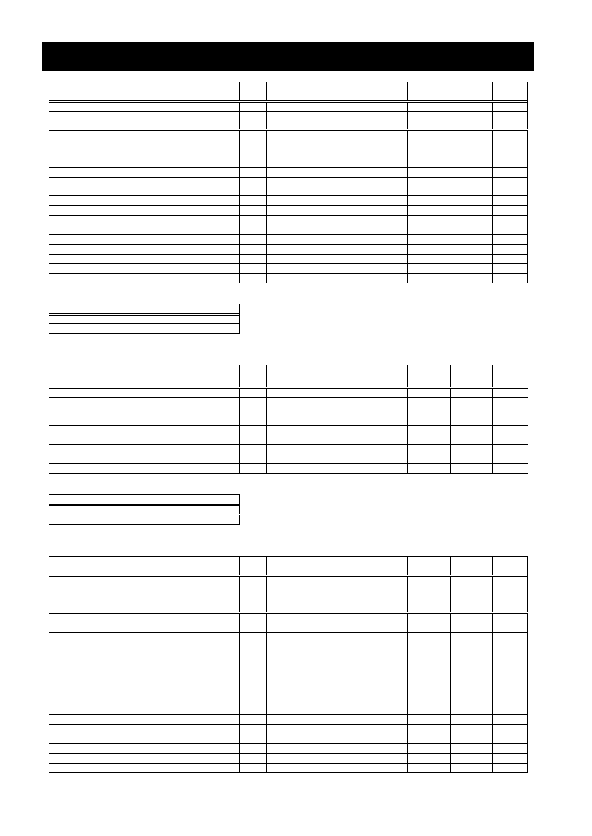
APPENDIX PARAMETER OBJECT LISTS
Magnifi-
Access
mand
172
Get/Set
C072
CommBitLengthSel (Param265)
173
Get/Set
C073
175
Get/Set
C075
178
Get/Set
C078
181
Get/Set
C081
182
Get/Set
C082
183
Get/Set
C083
185
Get/Set
C085
186
Get/Set
C086
187
Get/Set
C087
188
Get/Set
C088
123
Get/Set
C123
Magnifi-
Access
mand
2nd Allowable Motor (Param352)
103
Get/Set
H203
2nd Speed Response(Param354)
105
Get/Set
H205
106
Get/Set
H006
2nd StabilizedFactor (Param355)
106
Get/Set
H206
Function Inst Attr Size Monitoring/Setting Range
ZERO Speed Level (Param261) 1 163 2 0.00 to 100.00(Hz) 100 Get/Set C063
Data Command Sel (Param262) 1 170 1
CommSpeed Select (Param263) 1 171 1
Comm ID Select (Param264) 1
1
CommParitySelect (Param266) 1 174 1
Comm StopBit Sel (Param267) 1
Comm Wait Time (Param268) 1
O Adjustment (Param269) 1
OI Adjustment (Param270) 1
O2 Adjustment (Param271) 1
Therm-Adjustment (Param272) 1
AM Offset Adjust (Param273) 1
AMI Adjustment (Param274) 1
AMI OffsetAdjust (Param275) 1
1 1 to 32 1
1 7(7bit)/8(8bit) 1
1 1(1bit)/2(2bit) 1
2 0 to 1000(ms) 1
2 0 to 65530 1
2 0 to 65530 1
2 0 to 65530 1
2 0.0 to 1000.0 10
1 0.0 to 10.0(V) 10
1 0 to 255(%) 1
1 0.0 to 20.0( mA) 10
02(Operator)/03(RS485)/
04(Option 1)/05(Option 2)
02(loop back)/
03(2400bps)/04(4800bps)/
05(9600bps)/06(19200bps)
00(No Parity )/01(Even Parity )/
02(Odd Parity )
cation
1 Get/Set C070
1 Get/Set C071
1 Get/Set C074
rule
Support service
Service name Code
Get_Attribute_Single H’0E
Set_Attribute_Single H’10
(6) Extend Group C object Class ID=106
Function Inst Attr Size Monitoring/Setting Range
UP/DWN Selection (Param276) 1 101 1 00(Not keep)/01(Keep) 1 Get/Set C101
Reset Selection (Param277) 1 102 1
Reset f MacthSel (Param278) 1 103 1 00(0Hz start)/01(Synchronize) 1 Get/Set C103
OL Alarm Level 2 (Param279) 1 111 2 0 to 200(%) (constant current) 1 Get/Set C111
O ZeroAdjustment (Param280) 1 121 2 0 to 65530 1 Get/Set C121
OIZeroAdjustment (Param281) 1 122 2 0 to 65530 1 Get/Set C122
O2ZeroAdjustment (Param282) 1
2 0 to 65530 1
00(Reset at close)/
01(Reset at open)/
02(Only trip clear)
Magnifi-
cation
1 Get/Set C102
Access
rule
Com
Command
Support service
Service name Code
Get_Attribute_Single H’0E
Set_Attribute_Single H’10
(7) Extend Group H object Class ID=107
Function Inst Attr Size Monitoring/Setting Range
AutotuningSelect (Param283) 1 101 1
Motor Constant (Param284) 1 102 1
2nd Motor Constant (Param351) 2 102 1
Allowable Motor (Param285) 1 103 1
2
MotorPole Select (Param286) 1 104 1 0(2P)/1(4P)/2(6P)/3(8P) 1 Get/Set H004
2nd MotorPole Select(Param353) 2 104 1 0(2P)/1(4P)/2(6P)/3(8P) 1 Get/Set H204
Speed Response (Param287) 1 105 2 0.001 to 65.53 1000 Get/Set H005
2
StabilizedFactor (Param288) 1
2
00(Invalid)/01(Valid(not rotate))/
02(Valid(rotate))
00(Standard Motor)/
01(Offline Auto)/02(Online Auto)
00(Standard Motor)/
01(Offline Auto)/02(Online Auto)
00(0.20)/01(0.37)/02(0.40)/
03(0.55)/04(0.75)/05(1.10)/
06(1.50)/07(2.20)/08(3.00)/
09(3.70)/10(4.00)/11(5.50)/
12(7.50)/13(11.0)/14(15.0)/
15(18.5)/16(22.0)/17(30.0)/
18(37.0)/19(45.0)/20(55.0)/
21(75.0)
1 Same above 1
2 0.001 to 65.53 1000
2 0 to 255 1
2 0 to 255 1
cation
1 Get/Set H001
1 Get/Set H002
1 Get/Set H202
1 Get/Set H003
rule
Com
30
Page 35

APPENDIX PARAMETER OBJECT LISTS
Magnifi-
Access
122
Get/Set
H022
122
Get/Set
H222
133
Get/Set
H033
133
Get/Set
H233
134
Get/Set
H034
134
Get/Set
H234
150
Get/Set
H050
2nd PIProportionGain(Param366)
150
Get/Set
H250
151
Get/Set
H051
2nd PI Integrat-Gain (Param367)
151
Get/Set
H251
152
Get/Set
H052
2nd P ProportionGain(Param368)
152
Get/Set
H252
160
Get/Set
H060
Magnifi-
Access
mand
OP2 OpeSel OnErr (Param307)
102
Get/Set
P002
FeedbackOPenable (Param308)
110
Get/Set
P010
111
Get/Set
P011
112
Get/Set
P012
114
Get/Set
P014
115
Get/Set
P015
116
Get/Set
P016
Orient-CompRange (Param315)
117
Get/Set
P017
118
Get/Set
P018
119
Get/Set
P019
120
Get/Set
P020
121
Get/Set
P021
122
Get/Set
P022
144
Get/Set
P044
Function Inst Attr Size Monitoring/Setting Range
3rd StabilizedFactor (Param382) 3 106 2 0 to 255 1 Get/Set H306
Motor-Const R1 (Param289) 1 120 4
2nd Motor- Const R1 (Param356) 2 120 4 0.000 to 65.53(Ω) 1000 Get/Set H220
Motor-Const R2 (Param290) 1 121 4
2nd Motor- Const R2 (Param357) 2 121 4 0.000 to 65.53(Ω)) 1000 Get/Set H221
Motor-Const L (Param291) 1
2nd Motor- Const L (Param358) 2
Motor-Const I0 (Param292) 1 123 4 0.00 to 655.3( mH) 100 Get/Set H023
2nd Motor- Const I0 (Param359) 2 123 4 0.00 to 655.3( mH) 100 Get/Set H223
Motor-Const J (Param293) 1 124 4 0.001 to 9999(kgm2) 1000 Get/Set H024
2nd Motor- Const J (Param360) 2 124 4 0.001 to 9999(kgm2) 1000 Get/Set H224
Motor-Auto R1 (Param294) 1 130 4 0.000 to 65.53(Ω) 1000 Get/Set H030
2nd Motor-Auto R1 (Param361) 2 130 4 0.000 to 65.53(Ω) 1000 Get/Set H230
Motor-Auto R2 (Param295) 1 131 4
2nd Motor-Auto R2 (Param362) 2 131 4 0.000 to 65.53(Ω) 1000 Get/Set H231
Motor-Auto L (Param296) 1 132 4 0.00 to 655.3( mH) 100 Get/Set H032
2nd Motor-Auto L (Param363) 2 132 4 0.00 to 655.3( mH) 100 Get/Set H232
Motor-Auto I0 (Param297) 1
2nd Motor-Auto I0 (Param364) 2
Motor-Auto J (Param298) 1
2nd Motor-Auto J (Param365) 2
PIProportionGain (Param299) 1
2
PI Integrat-Gain (Param300) 1
2
P ProportionGain (Param301) 1
2
0Hz-SLV Limit (Param302) 1
2nd 0Hz-SLV Limit (Param369) 2 160 2 0.0 to 100(%) 10 Get/Set H260
PIProport-Gain2 (Param303) 1 170 2 0.0 to 1000(%) 10 Get/Set H070
PIIntegrat-Gain2 (Param304) 1 171 2 0.0 to 1000(%) 10 Get/Set H071
P Proport-Gain2 (Param305) 1 172 2 0.00 to 10.00 100 Get/Set H072
4 0.00 to 655.3( mH) 100
4 0.00 to 655.3( mH) 100
4 0.00 to 655.3( mH) 100
4 0.00 to 655.3( mH) 100
4 0.001 to 9999(kgm2) 1000
4 0.001 to 9999(kgm2) 1000
2 0.0 to 1000(%) 10
2 0.0 to 1000(%) 10
2 0.0 to 1000(%) 10
2 0.0 to 1000(%) 10
2 0.01 to 10.00 100
2 0.01 to 10.00 100
2 0.0 to 100(%) 10
0.000 to 65.53(Ω)
0.000 to 65.53(Ω)
0.000 to 65.53(Ω)
cation
1000 Get/Set H020
1000 Get/Set H021
1000 Get/Set H031
rule
Com
mand
Support service
Service name Code
Get_Attribute_Single H’0E
Set_Attribute_Single H’10
(8) Extend Group P object Class ID=109
Function Inst Attr Size Monitoring/Setting Range
OP1 OpeSel OnErr (Param306) 1 101 1 00(Trip)/01(Run) 1 Get/Set P001
Encoder Pulse No (Param309) 1
Control Mode Sel (Param310) 1
Pulse Train Mode (Param311) 1 113 1
Orient-Stop Pos (Param312) 1
Orient-Speed Set (Param313) 1
Orient-Direction (Param314) 1
Orient-CompDelay (Param316) 1
Elect-GearPosSel (Param317) 1
Elect-Gear Num (Param318) 1
Elect-Gear Dnom (Param319) 1
Feed-ForwardGain (Param320) 1
Pos-CtrlLoopGain (Param321) 1 123 2 0.00 to 100 100 Get/Set P023
Compensation R2 (Param322) 1 125 1 00(Invalid)/01(Valid) 1 Get/Set P025
Over Speed Level (Param323) 1 126 2 0.0 to 150(%) 10 Get/Set P026
SpeedErDetectLvl (Param324) 1 127 2 0.00 to 120(Hz) 100 Get/Set P027
DGInp-SelAcc/Dec (Param325) 1 131 1
OrientPosInp-Sel (Param326) 1 132 1
CommErrTime (Param327) 1
1
1
1
1 00(Trip)/01(Run) 1
1 00(Invalid)/01(Valid) 1
2 128 to 65000 1
1 00(ASR mode)/01(APR mode) 1
00(Mode 0)/01(Mode 1)/
02(Mode 2)
2 0 to 4095 1
2 0.00 to 120(Hz) 100
1 00(Forward)/01(Reverse) 1
2 0 to 10000 1
2 0.00 to 9.99(s) 100
1 00(Feedback)/01(Reference) 1
2 1 to 9999 1
2 1 to 9999 1
2 0.00 to 655.35 100
00(Operator)/01(Option 1)/
02(Option 2)
00(Operator)/01(Option 1)/
02(Option 2)
2 0.00 to 99.99(s) 100
cation
1 Get/Set P013
1 Get/Set P031
1 Get/Set P032
rule
Com
31
Page 36

APPENDIX PARAMETER OBJECT LISTS
Magnifi-
Access
mand
146
Get/Set
P046
147
Get/Set
P047
0,2,4,6,8,10,12,14,16,18,20,22,24,
Function Inst Attr Size Monitoring/Setting Range
CommTimOutAction (Param328) 1 145 1
Output Assembly (Param329) 1
Input Assembly(Param330) 1
Idle Mode Action (Param331) 1 148 1
Rpm chg Pole sel (Param332) 1 149 1
Support service
Service name Code
Get_Attribute_Single H’0E
Set_Attribute_Single H’10
cation
00(Trip)/01(Dec and trip)/
02(Hold last)/03(Free run stop)/
04(Deceleration stop)
1 20,21,100 1
1 70,71,101 1
00(Trip)/01(Dec and trip)/
02(Hold last)/03(Free run stop)/
04(Deceleration stop)
26,28,30,32,34,36,38
rule
Com
1 Get/Set P045
1 Get/Set P048
1 Get/Set P049
32
 Loading...