

Hitachi SJ700D-022L, SJ700D-004L, SJ700D-022H, SJ700D-037L, SJ700D-037H Quick Reference Manual
...
SJ700D-3 SERIES
Read through this Quick Reference Guide, and keep it handy for future reference.
HITACHI INVERTER
Quick Reference Guide
NT2311X

Introduction
No.
Revision content
Date of issue
Manual code
1
First edition
April, 2014
NT2311X
Introduction
Thank you for purchasing Hitachi SJ700D-3 Series Inverter. This Quick Reference Guide describes the contents of
planning the installation, installing, commissioning, using and servicing the Hitachi SJ700D-3 Series Inverter.
Please read this document and the instruction manual before operation to perfectly understand proper handling and
safety precautions for the product to ensure safety and proper usage. Before attempting installation, operation and
maintenance work, you should understand the knowledge of equipment, information of safety, caution and how to
use and service the inverter. You should also use the inverter by observing specifications described this guide and
prevent risks by performing maintenance.
This guide is “Quick Reference Guide”. Refer to "SJ700D-3 series Instruction Manual" on CD bundled with the
inverter for more information. If you use the inverter with optional products, also you should read the manuals for
those products. Note that this guide, the instruction manual and the manual for each optional product to be used
should be delivered to the end user of the inverter.
Handling of this Quick Reference Guide and bundled CD (the Instruction Manual)
- The contents of the guide and the CD are subject to change without prior notice.
- Even if you lose the guide and the CD, it will not be resupplied, so please keep it carefully.
- No part of the guide and the CD may be reproduced in any form without the publisher’s permission.
- If you find any incorrect description, missing description or have a question concerning the contents of these
manuals, please contact the publisher.
Revision History
- The current edition of this Quick Reference Guide also includes some corrections of simple misprints, missing
letters, misdescriptions and certain added explanations other than those listed in the above Revision History table.
Safety Instructions
CAUTION
- Many of the drawings in the Quick Reference Guide show the inverter with covers and/or parts blocking your view as
removed. Do not operate the inverter in the status shown in those drawings. If you have removed the covers and/or parts, be
sure to reinstall them in their original positions before starting operation, and follow all instructions in this Instruction
Manual when operating the inverter.
CAUTION
- Install the inverter on a non-flammable surface, e.g., metal. Otherwise, you run the risk of fire.
- Do not place flammable materials near the installed inverter. Otherwise, you run the risk of fire.
- When carrying the inverter, do not hold its top cover. Otherwise, you run the risk of injury by dropping the inverter.
- Prevent foreign matter (e.g., cut pieces of wire, sputtering welding materials, iron chips, wire, and dust) from entering the
inverter. Otherwise, you run the risk of fire.
- Install the inverter on a structure able to bear the weight specified in this Instruction Manual. Otherwise, you run the risk of
injury due to the inverter falling.
- Install the inverter on a vertical wall that is free of vibrations. Otherwise, you run the risk of injury due to the inverter falling.
- Do not install and operate the inverter if it is damaged or its parts are missing. Otherwise, you run the risk of injury.
- Install the inverter in a well-ventilated indoor site not exposed to direct sunlight. Avoid places where the inverter is exposed
to high temperature, high humidity, condensation, dust, explosive gases, corrosive gases, flammable gases, grinding fluid
mist, or salt water. Otherwise, you run the risk of fire.
- The inverter is precision equipment. Do not allow it to fall or be subject to high impacts, step on it, or place a heavy load on
it. Doing so may cause the inverter to fail.
WARNING
- Be sure to ground the inverter. Otherwise, you run the risk of electric shock or fire.
- Commit wiring work to a qualified electrician. Otherwise, you run the risk of electric shock or fire.
- Before wiring, make sure that the power supply is off. Otherwise, you run the risk of electric shock or fire.
- Perform wiring only after installing the inverter. Otherwise, you run the risk of electric shock or injury.
- Do not remove rubber bushings from the wiring section. Otherwise, the edges of the wiring cover may damage the wire,
resulting in a short circuit or ground fault.
CAUTION
- Make sure that the voltage of AC power supply matches the rated voltage of your inverter. Otherwise, you run the risk of
injury or fire.
- Do not input single-phase power into the inverter. Otherwise, you run the risk of fire.
- Do not connect AC power supply to any of the output terminals (U, V, and W). Otherwise, you run the risk of injury or fire.
- Do not connect a resistor directly to any of the DC terminals (PD, P, and N). Otherwise, you run the risk of fire.
- Connect an earth-leakage breaker to the power input circuit. Otherwise, you run the risk of fire.
- Use only the power cables, earth-leakage breaker, and magnetic contactors that have the specified capacity (ratings).
Otherwise, you run the risk of fire.
- Do not use the magnetic contactor installed on the primary and secondary sides of the inverter to stop its operation.
- Tighten each screw to the specified torque. No screws must be left loose. Otherwise, you run the risk of fire.
- Before operating, slide switch SW1 in the inverter, be sure to turn off the power supply. Otherwise, you run the risk of
electric shock and injury.
- Since the inverter supports two modes of cooling-fan operation, the inverter power is not always off, even when the cooling
fan is stopped. Therefore, be sure to confirm that the power supply is off before wiring. Otherwise, you run the risk of electric
shock and injury.
CAUTION
CAUTION
WARNING
Safety Instructions
Be sure to read this Quick Reference Guide and appended documents thoroughly before installing, operating,
maintaining, or inspecting the inverter. In this Quick Reference Guide, safety instructions are classified into two
levels, namely WARNING and CAUTION.
: Indicates that incorrect handling may cause hazardous situations, which may result in serious
personal injury or death.
: Indicates that incorrect handling may cause hazardous situations, which may result in
moderate or slight personal injury or physical damage alone.
Note that even a level situation may lead to a serious consequence according to circumstances.
Be sure to follow every safety instruction, which contains important safety information. Also focus on and observe
the items and instructions described under "Notes" in the text.
1. Installation
2. Wiring
i
Safety Instructions
WARNING
- While power is supplied to the inverter, do not touch any terminal or internal part of the inverter, check signals, or connect or
disconnect any wire or connector. Otherwise, you run the risk of electric shock or fire.
- Be sure to close the terminal block cover before turning on the inverter power. Do not open the terminal block cover while
power is being supplied to the inverter or voltage remains inside. Otherwise, you run the risk of electric shock.
- Do not operate switches with wet hands. Otherwise, you run the risk of electric shock.
- While power is supplied to the inverter, do not touch the terminal of the inverter, even if it has stopped. Otherwise, you run
the risk of injury or fire.
- If the retry mode has been selected, the inverter will restart suddenly after a break in the tripping status. Stay away from the
machine controlled by the inverter when the inverter is under such circumstances. (Design the machine so that human safety
can be ensured, even when the inverter restarts suddenly.) Otherwise, you run the risk of injury.
- Do not select the retry mode for controlling an elevating or traveling device because output free-running status occurs in retry
mode. Otherwise, you run the risk of injury or damage to the machine controlled by the inverter.
- If an operation command has been input to the inverter before a short-term power failure, the inverter may restart operation
after the power recovery. If such a restart may put persons in danger, design a control circuit that disables the inverter from
restarting after power recovery. Otherwise, you run the risk of injury.
- The [STOP] key is effective only when its function is enabled by setting. Prepare an emergency stop switch separately.
Otherwise, you run the risk of injury.
- If an operation command has been input to the inverter before the inverter enters alarm status, the inverter will restart
suddenly when the alarm status is reset. Before resetting the alarm status, make sure that no operation command has been
input.
- While power is supplied to the inverter, do not touch any internal part of the inverter or insert a bar in it. Otherwise, you run
the risk of electric shock or fire.
CAUTION
- Do not touch the heat sink, which heats up during the inverter operation. Otherwise, you run the risk of burn injury.
- The inverter allows you to easily control the speed of motor or machine operations. Before operating the inverter, confirm
the capacity and ratings of the motor or machine controlled by the inverter. Otherwise, you run the risk of injury.
- Install an external brake system if needed. Otherwise, you run the risk of injury.
- When using the inverter to operate a standard motor at a frequency of over 60 Hz, check the allowable motor speeds with
the manufacturers of the motor and the machine to be driven and obtain their consent before starting inverter operation.
Otherwise, you run the risk of damage to the motor and machine.
- During inverter operation, check the motor for the direction of rotation, abnormal sound, and vibrations. Otherwise, you run
the risk of damage to the machine driven by the motor.
WARNING
- Before inspecting the inverter, be sure to turn off the power supply and wait for 10 minutes or more. Otherwise, you run the
risk of electric shock. (Before inspection, confirm that the Charge lamp on the inverter is off and the DC voltage between
terminals P and N is 45 V or less.)
- Commit only a designated person to maintenance, inspection, and the replacement of parts. (Be sure to remove wristwatches
and metal accessories, e.g., bracelets, before maintenance and inspection work and to use insulated tools for the work.)
Otherwise, you run the risk of electric shock and injury.
WARNING
- Never modify the inverter. Otherwise, you run the risk of electric shock and injury.
CAUTION
- Do not discard the inverter with household waste. Contact an industrial waste management company in your area who can
treat industrial waste without polluting the environment.
3. Operation
4. Maintenance, inspection, and parts replacement
5. Others
ii

Safety Instructions
WARNING: This equipment must be installed, adjusted, and maintained by qualified engineers who have
expert knowledge of electric work, inverter operation, and the hazardous circumstances that
can occur. Otherwise, personal injury may result.
Caution for EMC (Electromagnetic Compatibility) (0.4kW-150kW)
The SJ700D series inverter conforms to the requirements of Electromagnetic Compatibility (EMC) Directive
(2004/108/EC). However, when using the inverter in Europe, you must comply with the following specifications and
requirements to meet the EMC Directive and other standards in Europe:
1. Power supply requirements
a. Voltage fluctuation must be -15% to +10% or less.
b. Voltage imbalance must be ±3% or less.
c. Frequency variation must be ±4% or less.
d. Total harmonic distortion (THD) of voltage must be ±10% or less.
2. Installation requirement
a. The integrated filter in the SJ700D series inverter must be enabled. (See chapter 2 Installation andWiring)
* When using the specific external filter for the SJ700D series inverter, please refer to the instruction
described in the dedicated guide book for the filter.
3. Wiring requirements
a. A shielded wire (screened cable) must be used for motor wiring, and the length of the cable must be
according to the following table (Table 1).
b. The carrier frequency must be set according to the following table to meet an EMC requirement (Table 1).
c. The main circuit wiring must be separated from the control circuit wiring.
4. Environmental requirements (to be met when a filter is used)
a. Ambient temperature must be within the range -10°C to +50°C.
b. Relative humidity must be within the range 20% to 90% (non-condensing).
c. Vibrations must be 5.9 m/s2 (0.6 G) (10 to 55 Hz) or less. (0.4 to 22kW)
2.94 m/s2 (0.3 G) (10 to 55Hz) or less. (30 to 150kW)
d. The inverter must be installed indoors (not exposed to corrosive gases and dust) at an altitude of 1,000 m
or less.
iii

Safety Instructions
model
cat.
cable
length(m)
carrier
frequency(kHz)
model
cat.
cable
length(m)
carrier
frequency(kHz)
SJ700D-004L
C3 5 2.5
SJ700D-007L
C3 5 2.5
SJ700D-007H
C3 5 2.5
SJ700D-015L
C3 5 2.5
SJ700D-015H
C3 5 2.5
SJ700D-022L
C3 5 2.5
SJ700D-022H
C3 5 2.5
SJ700D-037L
C3 5 2.5
SJ700D-037H
SJ700D-040H
C3 5 2.5
SJ700D-055L
C3 1 1
SJ700D-055H
C3 1 2.5
SJ700D-075L
C3 1 1
SJ700D-075H
C3 1 2.5
SJ700D-110L
C3 1 1
SJ700D-110H
C3 1 2.5
SJ700D-150L
C3 1 1
SJ700D-150H
C3 1 2.5
SJ700D-185L
C3 1 1
SJ700D-185H
C3 1 2.5
SJ700D-220L
C3 5 2.5
SJ700D-220H
C3 1 2.5
SJ700D-300L
C3 5 2.5
SJ700D-300H
C3 1 2.5
SJ700D-370L
C3 5 2.5
SJ700D-370H
C3 1 2.5
SJ700D-450L
C3 5 2.5
SJ700D-450H
C3 5 2.5
SJ700D-550L
C3 5 2.5
SJ700D-550H
C3 5 2.5
SJ700D-750H
C3
10
2.5
SJ700D-900H
C3
10
2.5
SJ700D-1100H
C3
10
2.5
SJ700D-1320H
C3
10
2.5
SJ700D-1500H
C3
10
2.5
Table 1
iv

Safety Instructions
Model No.
Required Torque (N.m)
Wire Range (AWG)
SJ700D-004L
1.8
14(Stranded only)
SJ700D-007L
1.8
14(Stranded only)
SJ700D-015L
1.8
14(Stranded only)
SJ700D-022L
1.8
14(Stranded only)
SJ700D-037L
1.8
10(Stranded only)
SJ700D-050L
3.0
8
SJ700D-055L
4.0
8
SJ700D-075L
4.0
6
SJ700D-110L
4.0
6-4
SJ700D-150L
4.9
2
SJ700D-185L
4.9
1
SJ700D-220L
8.8
1 or 1/0
SJ700D-300L
8.8
2/0 or Parallel of 1/0
SJ700D-370L
20.0
4/0 (Prepared wire only) or Parallel of 1/0
SJ700D-450L
20.0
4/0 (Prepared wire only) or Parallel of 1/0
SJ700D-550L
19.6
350 kcmil
(Prepared wire only) or Parallel of 2/0 (Prepared wire only)
Cautions for UL and cUL (0.4kW-150kW)
(Standard to comply with: UL508C, CSA C22.2 No14-5)
Warning Markings
GENERAL:
These devices are open type and/or Enclosed Type 1 (when employing accessory Type 1 Chassis Kit) AC Inverters
with three phase input and three phase output. They are intended to be used in an enclosure. They are used to
provide both an adjustable voltage and adjustable frequency to the ac motor. The inverter automatically maintains
the required volts-Hz ration allowing the capability through the motor speed range.
(1) “Use 60/75C CU wire only” or equivalent.
For models SJ700D series except for models SJ700D-055H, SJ700D-075H, SJ700D-110H.
(2) “Use 75C CU wire only” or equivalent.
For models SJ700D series except for SJ700D-075H, SJ700D-110H, SJ700D-055H.
(3) “Suitable for use on a circuit capable of delivering not more than 100,000rms symmetrical amperes,
240V maximum”. For models with suffix L.
(4) “Suitable for use on a circuit capable of delivering not more than 100,000 rms symmetrical amperes,
480V maximum”. For models with suffix H.
(5) “Install device in pollution degree 2 environment”
(6) “Maximum Surrounding Air Temperature 45 or 50C”
(7) “CAUTION - Risk of Electric Shock - Capacitor discharge time is at least 10 min.”
(8) ”Integral solid state short circuit protection does not provide branch circuit protection.
Branch circuit protection must be provided in accordance with the NEC and any additional local codes”
(9) “Solid State motor overload protection reacts with max. 120% of FLA”.
(10) Tightening torque and wire range for field wiring terminals are in the table below:
v

Safety Instructions
Model No.
Fuse Size (Maximum A)
Circuit Breaker (A)
Type
Rating Type
SJ700D-004L
J
30 A
SJ700D-004L
J
SJ700D-007L
J
30 A
SJ700D-007L
J
SJ700D-015L
J
30 A
SJ700D-015L
J
SJ700D-022L
J
30 A
SJ700D-022L
J
SJ700D-037L
J
30 A
SJ700D-037L
J
SJ700D-050L
J
30 A
SJ700D-050L
J
SJ700D-055L
J
100 A
SJ700D-055L
J
SJ700D-075L
J
100 A
SJ700D-075L
J
SJ700D-110L
J
100 A
SJ700D-110L
J
SJ700D-150L
J
125 A
SJ700D-150L
J
SJ700D-185L
J
125 A
SJ700D-185L
J
SJ700D-220L
J
125 A
SJ700D-220L
J
SJ700D-300L
J
225 A
SJ700D-300L
J
SJ700D-370L
J
225 A
SJ700D-370L
J
SJ700D-450L
J
250 A
SJ700D-450L
J
SJ700D-550L
J
300 A
SJ700D-550L
J
Model No.
Required Torque (N.m)
Wire Range (AWG)
SJ700D-007H
1.8
14(Stranded only)
SJ700D-015H
1.8
14(Stranded only)
SJ700D-022H
1.8
14(Stranded only)
SJ700D-037H
1.8
14(Stranded only)
SJ700D-040H
1.8
14(Stranded only)
SJ700D-055H
4.0
12
SJ700D-075H
4.0
10
SJ700D-110H
4.0
8
SJ700D-150H
4.9
6
SJ700D-185H
4.9
6
SJ700D-220H
4.9
6 or 4
SJ700D-300H
4.9
3
SJ700D-370H
20.0
1
SJ700D-450H
20.0
1
SJ700D-550H
20.0
2/0
SJ700D-750H
20.0
Parallel of 1/0
SJ700D-900H
20.0
Parallel of 1/0
SJ700D-1100H
35.0
Parallel of 3/0
SJ700D-1320H
35.0
Parallel of 3/0
SJ700D-1500H
35.0
Parallel of 3/0
(11) Distribution fuse / circuit breaker size marking is included in the manual to indicate that the unit shall be
connected with a listed inverse time circuit breaker, rated 600 V with the current ratings as shown in the
table below:
vi

Safety Instructions
Model No.
Fuse Size (Maximum A)
Circuit Breaker (A)
Type
Rating
Type
SJ700D-007H
J
20 A
SJ700D-007H
J
SJ700D-015H
J
20 A
SJ700D-015H
J
SJ700D-022H
J
20 A
SJ700D-022H
J
SJ700D-037H
J
20 A
SJ700D-037H
J
SJ700D-040H
J
20 A
SJ700D-040H
J
SJ700D-055H
J
40 A
SJ700D-055H
J
SJ700D-075H
J
40 A
SJ700D-075H
J
SJ700D-110H
J
40 A
SJ700D-110H
J
SJ700D-150H
J
75 A
SJ700D-150H
J
SJ700D-185H
J
75 A
SJ700D-185H
J
SJ700D-220H
J
75 A
SJ700D-220H
J
SJ700D-300H
J
100 A
SJ700D-300H
J
SJ700D-370H
J
100 A
SJ700D-370H
J
SJ700D-450H
J
150 A
SJ700D-450H
J
SJ700D-550H
J
150 A
SJ700D-550H
J
SJ700D-750H
J
225 A
SJ700D-750H
J
SJ700D-900H
J
225 A
SJ700D-900H
J
SJ700D-1100H
J
300 A
SJ700D-1100H
J
SJ700D-1320H
J
350 A
SJ700D-1320H
J
Note) Please select an appropriate fuse or an appropriate circuit breaker for a system.
(12) “Field wiring connection must be made by a UL Listed and CN closed-loop terminal connector sized for the
wire gauge involved. Connector must be fixed using the crimp tool specified by the connector
manufacturer.”
(13) “Motor over temperature protection is not provided by the drive.”
DANGER! RISQUE DE BLESSURE OU DE CHOC ELECTRIQUE
- Lire attentivement le manuel avant l’installation et suivre les instructions
- Avant d’intervenir dans le variateur, couper le circuit de puissance et attendre 10 minutes avant d’ouvrir le capot
vii

SJ700-2 to SJ700D-3
Subject
SJ700-2
SJ700D-3
Point!
Dual rating
Constant torque/
Variable torque
N/A
Selectable
If the inverter drives the light
load application (e.g. fan pump
application), you can choose
the one size smaller capacity
inverter than the motor capacity,
which allows you to reduce the
total cost of your system.
Easy sequence
(EzSQ) – Drive
program function
Process with 1 task.
Supporting 5 tasks
processing with
improved user
friendliness.
The inverter processes 5 tasks at
the same time, which allows you
to realize 5 times faster EzSQ
processing in maximum.
Optional LCD
Operator
WOP operator
(2-line LCD)
Full compatibility with
WOP operator
(5-line LCD and
multi-language)
WOP, the optional LCD
Operator, provides several user
friendliness;
− Multi data monitoring
− Parameter configuration as
monitoring data
− Parameter / Program copy
− Multi-language display
RS-485 serial
communications
19.2kbps (maximum)
115.2kbps (maximum),
and so on.
Approx. 6 times faster
communication in comparison
with the former model are
supported. In addition, some
communication commands are
newly supported.
Initialization
After setting b084
(initialization selection),
press some keys.
In addition to the
conventional method,
executing initialization
by a parameter is
possible.
(Select b084 and
b180=01 : enable the
initializing)
You can initialize easily only by
setting the parameter and no
special procedure is required
Phase loss
protection
Phase loss input
protection
Phase loss input
protection
Phase loss output
protection
Protection function expands to
not only input side but output
side, which provides more
reliable protection against the
phase loss.
The Hitachi SJ700D-3 series succeed the SJ700-2 series with the additional and enhanced features.
The table below is a belief summary of the major improved features.

Contents
Start-up Commissioning the drive
S.1 Quick installation and commissioning flowchart ................................................................................... S - 2
S.2 Instructing in using the panel.................................................................................................................. S - 3
S.3 Example of I/O connections ................................................................................................................... S - 4
S.4 Basic Parameter Setting to Drive Motor ................................................................................................. S - 8
S.4.1 Setting Frequency command source and Run command source .............................................. S - 8
S.4.2 Frequency command source selection ..................................................................................... S - 9
S.4.3 Run command source selection ............................................................................................... S - 11
S.5 Selecting the control mode ..................................................................................................................... S - 13
Chapter 1 Overview
1.1 Inspection of the Purchased Product ············································································· 1 - 2
1.1.1 Inspecting the product·················································································· 1 - 2
1.1.2 Quick Reference Guide and Instruction Manual···················································· 1 - 2
1.2 Method of Inquiry and Product Warranty ······································································· 1 - 3
1.2.1 Method of inquiry ······················································································ 1 - 3
1.2.2 Product warranty ························································································ 1 - 3
1.2.3 Warranty Terms ························································································· 1 - 3
1.3 Exterior Views and Names of Parts ·············································································· 1 - 4
Chapter 2 Installation and Wiring
2.1 Installation ·········································································································· 2 - 2
2.1.1 Precautions for installation ············································································ 2 - 3
2.1.2 Backing plate ································ ···························································· 2 - 5
2.2 Wiring ··············································································································· 2 - 6
2.2.1 Terminal connection diagram and explanation of terminals and switch settings ··············· 2 - 7
2.2.2 Wiring of the main circuit ············································································· 2 - 10
2.2.3 Wiring of the control circuit ··········································································· 2 - 19
2.2.4 Wiring of the digital operator ········································································· 2 - 20
Chapter 3 Operation
3.1 Operating Methods ································································································· 3 - 2
3.2 How to operate the Digital Operator (OPE-SBK) ····························································· 3 - 4
3.2.1 Names and functions of components ······························································· 3 - 4
3.2.2 Code display system and key operations ···························································· 3 - 5
Chapter 4 List of Data Settings
4.1 Precautions for Data Setting ······················································································ 4 - 2
4.2 Monitoring Mode ·································································································· 4 - 2
4.3 Function Mode ····································································································· 4 - 3
4.4 Extended Function Mode ························································································· 4 - 4
Chapter 5 Error Codes
5.1 Error Codes and Troubleshooting ················································································ 5 - 2
5.1.1 Error codes ······························································································ 5 - 2
5.1.2 Trip conditions monitoring ············································································ 5 - 4
5.2 Warning Codes ····································································································· 5 - 5
Chapter 6 Specifications
6.1 Specifications ······································································································· 6 - 2
6.2 External dimensions ······························································································· 6 - 5

Contents
(Memo)

Start-up Commissioning the drive
This chapter contains quick installation and commissioning flowchart to drive the motor.
S.1 Quick installation and commissioning flowchart ............. S - 2
S.2 Instructing in using the panel ........................................... S - 3
S.3 Example of I/O connections ............................................. S - 4
S.4 Basic Parameter Setting to Drive Motor .......................... S - 8
S.5 Selecting the control mode ............................................... S - 13

Start-up Commissioning the drive
Start to confirm
Product inspection
Refer to chapter 1.
Installing
Wiring
Selecting the suitable control mode
End of Confirmation and start to drive
ON
Motor
Speed
Time
RUN
Frequency
command
Motor
speed
Refer to section 2.1.
・Installing
Initial settings of
SJ700D-****FF3
Initial settings of
3
Example 1
Example 2
Example 3
Example 4
Frequency
command
Data setting
(Operator)
External analog signal
(Voltage)
Data setting
(Multi-speed)
External analog signal
(Voltage and Current)
Drive
command
Push key
(Operator)
Push key
(Operator)
External signal
Before setting parameters,
see section S.2.
For basic settings to drive
the motor, see section S.4.
Example of basic setup
the motor, see section S.3.
Setting of control mode
see section S.5
Refer to section 2.2.
・Wiring
What are the desired sources
RUN command?
Setting of commands
S.1 Quick installation and commissioning flowchart
command
(IO connection) to drive
for giving frequency and
SJ700D-****FEF
External signal
S - 2

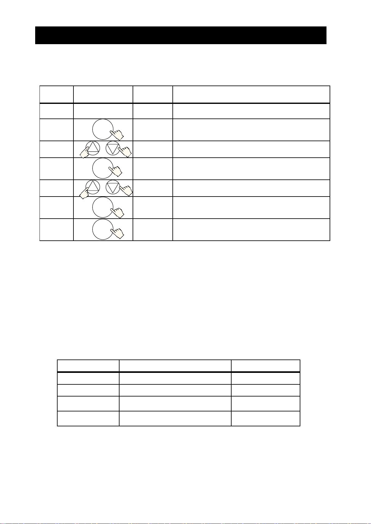
Start-up Commissioning the drive
Key
Operation
Display(Example)
Use examples (*** is a three digit number)
d001 ←→ 0.00
(Frequency monitor)
In case d*** or F*** display on the panel, indication changes
between parameters and data with pushing FUNC key.
A--- → A044
↑ ↓
A044 ← 00
(Control mode)
In case A***, B***, C***, H***, P*** or U*** display on the
panel, indication changes among A--- (head of group), A044
(parameter) and 00 (data) with pushing FUNC key.
00 → A044
(Control mode)
When the panel indication displays 00 (data), the inverter saves the
displayed value as the new setting with pushing the STR key, and
panel indication changes to the A044 (parameter). The saved data
are held even if the power supply to the inverter is turned off.
d001→d002→…
→F004→A---→…
Panel Indication scrolls up through d***, F*** and the heads of
group (for example A---, B---, C---, H---, P--- and U---).
1.00→1.01→…
A011→A012→…
The value increases if panel indication displays parameters or data.
Holding the key down changes the value faster.
A---→F004→…→
d002→d001→…
Panel indication scrolls down through d***, F*** and the heads of
group (for example A---, B---, C---, H---, P--- and U---).
1.01→1.00→…
A012→A011→…
The value decreases if panel indication displays parameters or data.
Holding the key down changes the value faster.
Simultaneously
A044→’A’044
Pushing simultaneously enables to change each digit directly.
Operating of
the blinking digit is as follows.
0.00→’0’.00
FUNC
STR
1
2
2
1
A
ALARM
POWER
%
RUN
PRG
V
Hz
STR
FUNC
RUN
STOP/
RESET
kW
STR
FUNC
1
2
Left
Right/Save
Increasing
Decreasing
S.2 Instructing in using the panel
This section describes how to use the operator to
change the settings.
For more information, refer to the SJ700D-3 manual or
section 3.2 : How to operate the Digital Operator.
Indication of using the control panel Standard Operator (OPE-SBK)
*) In some cases parameters and data are discontinuous.
(For more information, refer to SJ700D-3 manual.)
S - 3

Start-up Commissioning the drive
Parameter
Details
Setting data
A001
Digital Operator
A002
Digital Operator
F001
Output frequency setting
.Note)
ELB
R/L1
S/L2
T/L3 R T
R0
T0
P
PD N RB
U
V
W
M
3-phase induction motor
RUN
STOP/
RESET
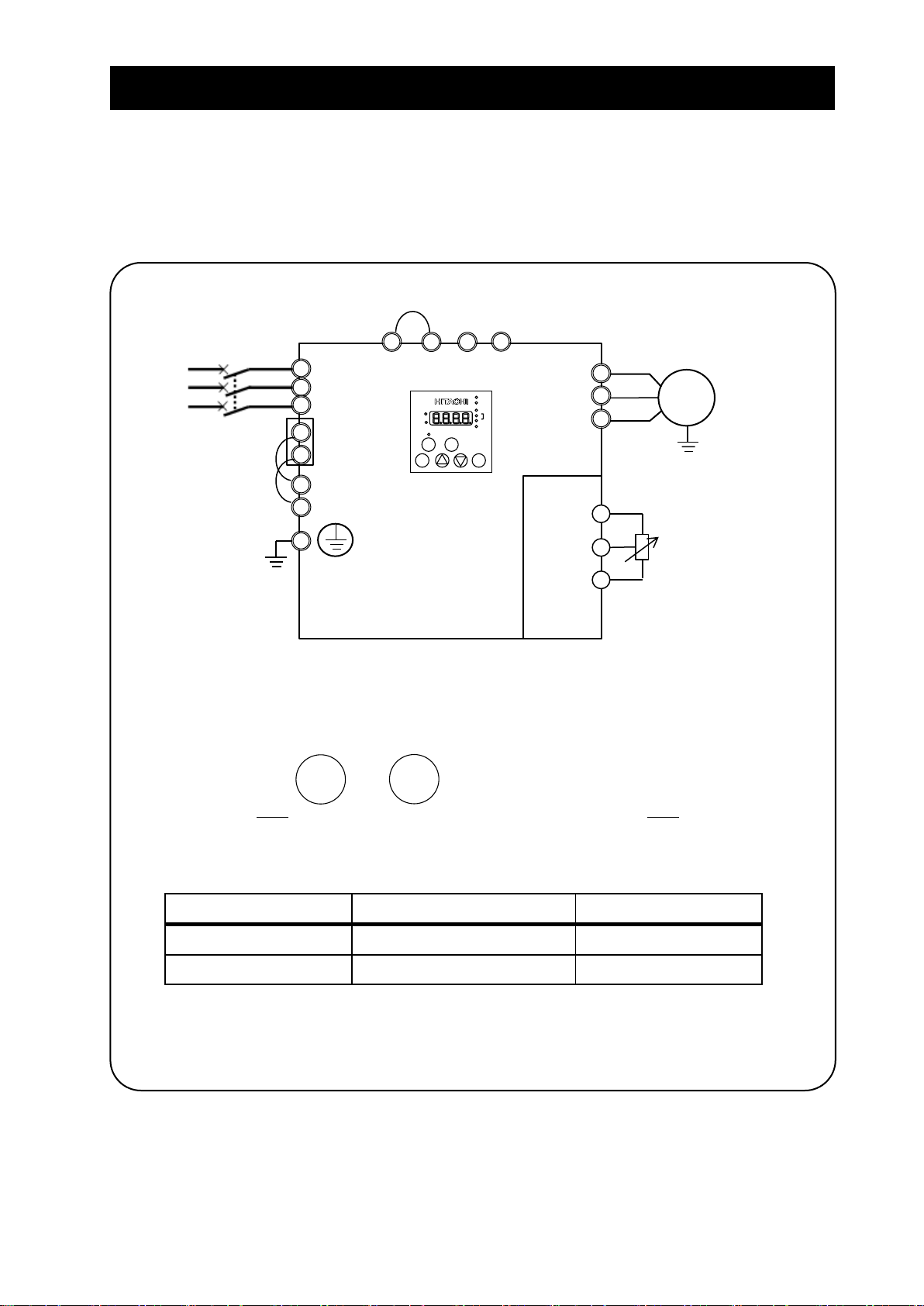
S.3 Example of I/O connections
Example 1: Frequency command source Setting data in F001 (Digital Operator)
Run command source RUN/STOP key (Digital Operator)
*) SJ700D-****FF3 (Initial settings)
(1) I/O connections
(2) Operation
Frequency: By using the digital operator, set the frequency command into parameter F001.
Run/Stop: Push the key and on the digital operator to run and stop.
*) Refer to section S.4.2 for changing the frequency command source and section S.4.3 for changing the run
command source.
(3) Parameter settings
Note) Initial settings are 0.00Hz. You need to set the appropriate data.
S - 4
Start-up Commissioning the drive
Parameter
Details
Setting data
A001
Control circuit terminal block
A002
Digital Operator
H O L
Potentiometer
R/L1
S/L2
T/L3
R T R0
T0
P
PD N RB
ELB
U
V
W
M
3-phase induction motor
RUN
STOP/
RESET
Example 2: :Frequency command source External potentiometer (Control terminal)
Run command source RUN/STOP key (Control panel)
(1) I/O connections
(2) Operation
Frequency: Set the frequency command via a potentiometer connected to H/O/L terminal.
Run/Stop: Push the key and to run and stop.
*) Refer to section S.4.2 for changing the frequency command source and section S.4.3 for changing the run
command source.
(3) Parameter settings
S - 5

Start-up Commissioning the drive
Parameter
Details
Setting data
A001
Digital Operator
A002
Control circuit terminal block
A020
Multi speed 1 and 2 are not active.
.Note)
A021
Multi speed 1is active and
multi speed 2 is not active.
.Note)
A022
Multi speed 1is not active and
multi speed 2 is active.
.Note)
FW
8:RV
CM1
Forward
7:CF1
6:CF2
P24
PLC
Reverse
Multi-speed1
Multi-speed2
CM1
P24
PLC
Sink logic
Source logic
R/L1
S/L2
T/L3
R
T
R0
T0
P
PD N RB
ELB
U
V
W
M
3-phase induction motor
Example 3: Frequency command source Setting data in F001 (Control panel) + multi speed select
Run command source External signal (Control terminal)
(1) I/O connections
*) In case of SJ700D-****FUF3, you need to set C006=03 and C016=00.
*) You need to set multi speed frequency command into parameters (from A020 to A022).
*) Refer to section S.4.2 for changing the frequency command source and section S.4.3 for changing the run
command source.
(2) Operation
Frequency: By using the multi speed terminals, set the frequency command.
Run/Stop: Using the forward / reverse terminal to run and stop.
(3) Parameter settings
Note) Initial settings are 0.00Hz. You need to set the appropriate data.
S - 6

Start-up Commissioning the drive
Parameter
Details
Setting data
A001
Control circuit terminal block
A002
Control circuit terminal block
FW
8:RV
CM1
Forward
2:AT
P24
PLC
Reverse
Analog select
CM1
P24
PLC
Sink logic
Source logic
R/L1
S/L2
T/L3 R T
R0
T0
P
PD N RB
OI O L
Voltage source
(0V to 10V)
Current source
(4mA to 20mA)
ELB
U
V
W
(+)
(-)
(+)
(-)
M
3-phase induction motor
Example 4: Frequency command source External analog voltage source and current source (Control terminal)
Run command source External signal (Control terminal)
*) SJ700D-****FEF3/FUF3 (Initial settings)
(1) I/O connections
*) Refer to S.4.2 for changing the frequency command source and S.4.3 for changing the run
command source.
(2) Operation
Frequency: Using the voltage source and current source to set the frequency command with analog
select terminal (AT terminal: OFF: Voltage command / ON: Current command).
* AT terminal is used to switch the analog input O and OI to which the inverter refers as the
frequency command. (e.g. When AT terminal is OFF, the inverter outputs the frequency
according to the voltage input given to the O terminal)
Run/Stop: Using the forward / reverse terminal to run and stop.
(3) Parameter settings
S - 7

Start-up Commissioning the drive
Parameter
Detail
Data range
Initial settings
****FF3
****FEF3
****FUF3
A001
Frequency source
00(keypad potentiometer)
01(control circuit terminal block)
02(operator)
03(RS485)
04(option 1)
05(option 2)
06(pulse-string input)
07(easy sequence)
10(operation function result)
02
01
A002
Run command source
01(control circuit terminal block)
02(operator)
03(RS485)
04(option 1)
05(option 2)
02
01
S.4 Basic Parameter Setting to Drive Motor
S.4.1 Setting Frequency command source and Run command source
This section describes how to drive the motor with SJ700D briefly.
The frequency and run command are necessary to drive the motor with the inverter.
In many cases, these sources are set as below;
Setting the frequency : (A) Data settings (Digital operator)
(B) Via external analog signals (Control terminal)
Run and stop : (A) RUN / STOP key (Digital operator)
(B) Via external signal (Control terminal)
The frequency command and Run command sources can be changed by the parameter A001 (Frequency command
source) and A002 (Run command source) respectively.
In addition to the basic setting mentioned above, there are several options for A001 and A002 setting.
*) This chapter explains 01(control circuit terminal block) and 02(operator) mainly.
S - 8

Start-up Commissioning the drive
Procedure
Key operation
Indication
Details
1-1
.
After powering up of the inverter, the operator displays 0.00,
output frequency monitor (d001)
1-2
Indication changes from data display (0.00) to parameter
display (d001).
1-3
or
Push the key and select the head of Group A.
1-4
Push the key and indication changes from A--- to A001.
1-5
Push the key and indication changes to 02(operator).
1-6
Push the key and change from 02 to 01 (control circuit
terminal block).
1-7
Push the key and indication changes A001 (Data save).
1-8
.
By pushing the key for more than three seconds,
indication changes to the output frequency data (d001).
(It depends on b038 setting)
Procedure
Key operation
Indication
Details
1-5’
Push the key and indication changes to 01(control circuit
terminal block).
1-6’
Push the key and change the data to 02 (operator).
FUNC
2
1
FUNC
FUNC
2
STR
FUNC
FUNC
1
S.4.2 Frequency command source selection
Key operation to set A001
****FF3 : Change A001 from 02 (operator) to 01 (control circuit terminal block).
****FEF3/FUF3 : Change from 01 (control circuit terminal block) to 02 (operator).
*) Replace the procedure 1-5 and 1-6 in the list above with 1-5’ and 1-6’ in the list below.
S - 9
Start-up Commissioning the drive
Procedure
Key operation
Indication
Details
1
.
After powering up of the inverter, the operator displays
0.00, output frequency monitor (d001)
2
Indication changes from data (0.00) to parameter (d001).
3
or
Push the key and select F001 (setting frequency).
4
.
Push the key and indication changes setting frequency.
5
or
.
(Example) Set the frequency to 40Hz.
6
Push the key and indication goes back to F001 (Data save).
note)
7
.
By pushing the key for more than three seconds,
the indication changes to the output frequency data.
(It depends on b038 setting)
Parameters
Condition
Setting
A001
Operator
*1)
A020
Multi speed 1 and 2 are not active.
.*2)
A021
Multi speed 1is active and
multi speed 2 is not active.
.*2)
A022
Multi speed 1is not active and
multi speed 2 is active.
.*2)
FUNC
2
1
FUNC
2
1
STR
FUNC
Setting frequency command
(A) A001=02: Digital operator
With this setting, the value set in the parameter F001 defines the target frequency of the inverter.
The procedure below shows an example of a procedure to set F001=40Hz.
note) In case of the setting A001=02, on displaying the output frequency, the setting frequency can change by the
up and down keys.
(B) A001=01: Control terminal
The frequency command can be changed in accordance with the analog input given to the O/OI terminal on the
control terminal by using a potentiometer (connected to H/O/L terminal) or an analog voltage / current supply.
With this setting, the parameter F001 indicates the frequency command value given via the control terminal.
Please refer to the instruction manual for the detailed information about the analog input (e.g. adjustment of he
start / end value).
(C) Multi-speed selection – Binary operation
The inverter can store several target frequencies (up to 16), which is useful to define such low / middle / high
frequencies and those frequencies are switched by external signals. The actual target frequency is selected from
those pre-set frequencies in accordance with the signal status of the multi speed inputs. This part describes an
example using 3 frequency sets.
*1) In case multi speed 1 and 2 are not active, the setting of A001 defines the frequency command source.
In case of A001=02, and if multi speed 1 and 2 are not active, F001 adopts the A020 value.
*2) Initial settings are 0.00Hz. You should set the appropriate data.
S - 10
Start-up Commissioning the drive
Procedure
Key operation
Indication
Details
2-1
.
After powering up of the inverter, the operator displays
0.00, output frequency monitor (d001)
2-2
Indication changes from data (0.00) to parameter (d001).
2-3
or
Push the key and select the head of Group A.
2-4
Push the key and indication changes to A001.
2-5
Push the key and select A002 (Run command source).
2-6
Push the key and indication changes to 02(operator).
2-7
Push the key and change the data to 01 (control circuit
terminal block).
2-8
Push the key and indication changes to A002 (Data save).
2-9
.
By pushing the key for more than three seconds,
indication changes to the output frequency data.
(It depends on b038 setting)
Procedure
Key operation
Indication
Details
2-6’
Push the key and indication changes to 01 (control circuit
terminal block).
2-7’
Push the key and change to 02(operator).
FUNC
2
1
FUNC
1
FUNC
2
STR
FUNC
FUNC
1
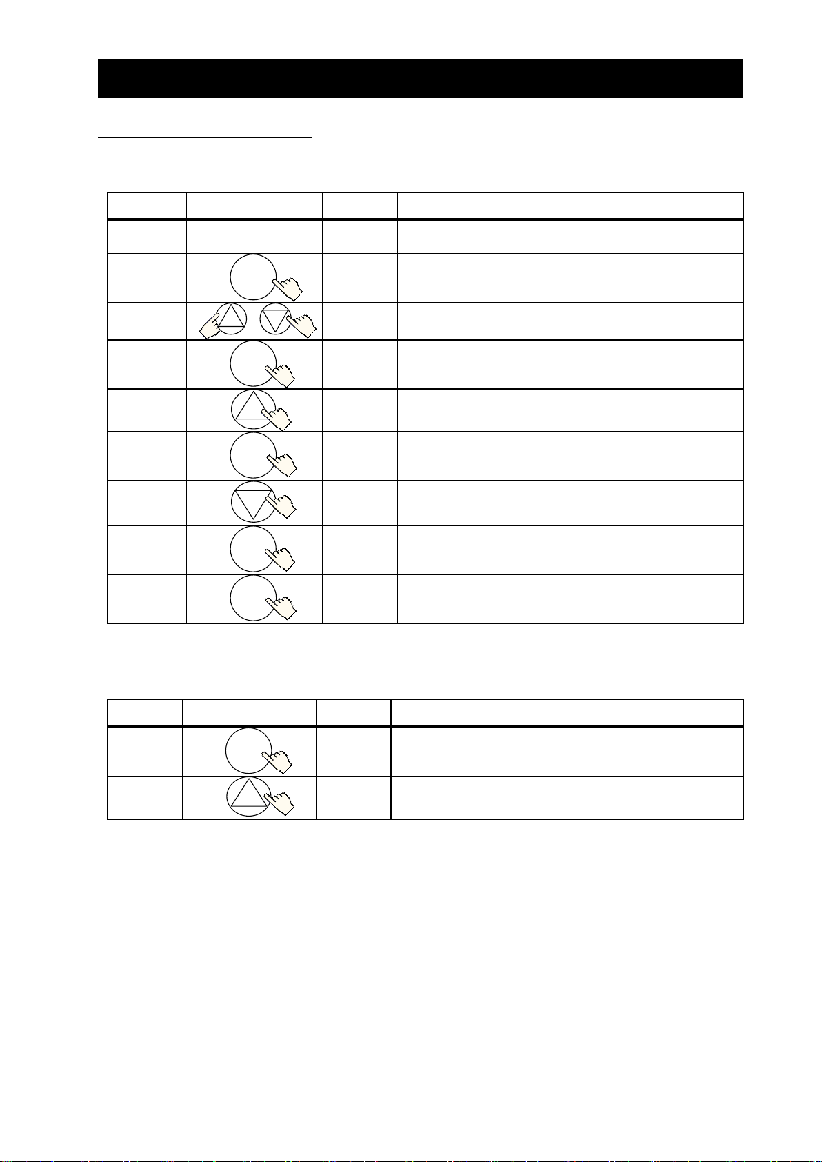
S.4.3 Run command source selection
Key operation to set A002
****FF3 : Change from 02 (operator) to 01 (control circuit terminal block).
****FEF3/FUF3 : Change 01 (control circuit terminal block) to 02 (operator).
*) Replace the procedure 2-6 and 2-7 on the list above with 2-6’ and 2-7’ in the list below.
S - 11

Start-up Commissioning the drive
RUN
STOP/
ON
Motor
Speed
Time
RUN
command
Frequency
command
Motor
speed
Operating run command
(A) A001=02: Digital operator
RUN and STOP key on the digital operator allows you to start and stop the motor respectively.
RUN: STOP:
RESET
*) Changing the rotatory direction can be done by changing the parameter F004, keypad run key routing or to
exchange any two phases of the wiring to the motor. Before wiring, you should confirm that the power supply
to the inverter has been cut off.
(B) A001=01: Control terminal
You can start and stop the motor operation via the FW terminal (forward rotation) or RV terminal (Reverse
rotation).
In case of terminal FW:
Sink logic (short between P24 and PLC)
FW-CM1 short: The inverter runs the motor in the forward direction --- RUN command is active.
FW-CM1 open: The inverter decelerates and stops the motor --- RUN command is not active.
Source logic (short between CM1 and PLC)
FW-P24 short: The inverter runs the motor in the forward direction --- RUN command is active.
FW-P24 open: The inverter decelerates and stops the motor --- RUN command is not active.
S - 12

Start-up Commissioning the drive
Check
In case you want to drive fun, pump or light load
application :
-Using the reduced torque mode (A044=01)
-Use the light load mode (b049=01) to drive the motor
with the one size smaller inverter.
In case you want to set the characteristic of
voltage/frequency freely :
-Using Free V/f mode (A044=02)
In case you want to drive the application which
requires high torque control without the motor
feedback :
-Using sensor-less vector mode (A044=03)*
In case you want to drive the application which
requires the high torque control at low frequency range
without the motor feedback.
-Using 0Hz sensor-less vector mode (A044=04)*
In case you want to
- drive the application which requires high torque
control
- drive the application which requires the position
control with the motor feedback :
-Using vector control mode (A044=05)*
S.5 Selecting the control mode
The SJ700D-3 inverter series provides several options for motor control to satisfy various application
requirements. Please choose a suitable control mode for your application by referring to the table below.
Initial setting of A044 is 00 (V/f control mode).
*) Depending on the load, applying the one size bigger inverter may be required. For more information,
refer to SJ700D-3 manual.
S - 13

Start-up Commissioning the drive
(Memo)
S - 14

Chapter 1 Overview
This chapter describes the inspection of the purchased product, the product warranty, and the
names of parts.
1.1 Inspection of the Purchased Product ······· 1 - 2
1.2 Method of Inquiry and Product Warranty · 1 - 3
1.3 Exterior Views and Names of Parts ········ 1 - 4
 Loading...