

Hitachi SJ700D-110L, SJ700D-055L, SJ700D-150L, SJ700D-185L, SJ700D-220L Instruction Manual
...
HITACHI INVERTER
SJ700D-3 SERIES
INSTRUCTION MANUAL
Read through this Instruction Manual, and keep it handy for future reference.
NT231X

Introduction
Introduction
Thank you for purchasing Hitachi SJ700D-3 Series Inverter. This Instruction Manual describes the contents of
planning the installation, installing, commissioning, using and servicing the Hitachi SJ700D-3 Series Inverter.
Please read this document before operation to perfectly understand proper handling and safety precautions for the
product to ensure safety and proper usage. Before attempting installation, operation and maintenance work, you
should understand the knowledge of equipment, information of safety, caution and how to use and service the
inverter. You should also use the inverter by observing specifications described this guide and prevent risks by
performing maintenance.
If you use the inverter with optional products, also you should read the manuals for those products. Note that this
instruction manual and the manual for each optional product to be used should be delivered to the end user of the
inverter.
Handling of this Instruction Manual (bundled CD)
- The contents of the Instruction Manual are subject to change without prior notice.
- Even if you lose the Instruction Manual, it will not be resupplied, so please keep it carefully.
- No part of the Instruction Manual may be reproduced in any form without the publisher’s permission.
- If you find any incorrect description, missing description or have a question concerning the contents of these
manuals, please contact the publisher.
Revision History
No.
Revision content
Date of issue
Manual code
1
First edition
June, 2014
NT231X
- The current edition of this the Instruction Manual also includes some corrections of simple misprints, missing
letters, misdescriptions and certain added explanations other than those listed in the above Revision History
table.
Safety Instructions
i
Safety Instructions
Be sure to read this Quick Reference Guide and appended documents thoroughly before installing, operating,
maintaining, or inspecting the inverter. In this Quick Reference Guide, safety instructions are classified into two levels,
namely WARNING and CAUTION.
: Indicates that incorrect handling may cause hazardous situations, which may result in serious
personal injury or death.
: Indicates that incorrect handling may cause hazardous situations, which may result in moderate
or slight personal injury or physical damage alone.
Note that even a level situation may lead to a serious consequence according to circumstances.
Be sure to follow every safety instruction, which contains important safety information. Also focus on and observe the
items and instructions described under "Notes" in the text.
CAUTION
- Many of the drawings in the Quick Reference Guide show the inverter with covers and/or parts blocking your view as
removed. Do not operate the inverter in the status shown in those drawings. If you have removed the covers and/or parts,
be sure to reinstall them in their original positions before starting operation, and follow all instructions in this Instruction
Manual when operating the inverter.
1. Installation
CAUTION
- Install the inverter on a non-flammable surface, e.g., metal. Otherwise, you run the risk of fire.
- Do not place flammable materials near the installed inverter. Otherwise, you run the risk of fire.
- When carrying the inverter, do not hold its top cover. Otherwise, you run the risk of injury by dropping the inverter.
- Prevent foreign matter (e.g., cut pieces of wire, sputtering welding materials, iron chips, wire, and dust) from entering the
inverter. Otherwise, you run the risk of fire.
- Install the inverter on a structure able to bear the weight specified in this Instruction Manual. Otherwise, you run the risk of
injury due to the inverter falling.
- Install the inverter on a vertical wall that is free of vibrations. Otherwise, you run the risk of injury due to the inverter falling.
- Do not install and operate the inverter if it is damaged or its parts are missing. Otherwise, you run the risk of injury.
- Install the inverter in a well-ventilated indoor site not exposed to direct sunlight. Avoid places where the inverter is exposed
to high temperature, high humidity, condensation, dust, explosive gases, corrosive gases, flammable gases, grinding fluid
mist, or salt water. Otherwise, you run the risk of fire.
- The inverter is precision equipment. Do not allow it to fall or be subject to high impacts, step on it, or place a heavy load on
it. Doing so may cause the inverter to fail.
2. Wiring
WARNING
- Be sure to ground the inverter. Otherwise, you run the risk of electric shock or fire.
- Commit wiring work to a qualified electrician. Otherwise, you run the risk of electric shock or fire.
- Before wiring, make sure that the power supply is off. Otherwise, you run the risk of electric shock or fire.
- Perform wiring only after installing the inverter. Otherwise, you run the risk of electric shock or injury.
- Do not remove rubber bushings from the wiring section. Otherwise, the edges of the wiring cover may damage the wire,
resulting in a short circuit or ground fault.
CAUTION
- Make sure that the voltage of AC power supply matches the rated voltage of your inverter. Otherwise, you run the risk of
injury or fire.
- Do not input single-phase power into the inverter. Otherwise, you run the risk of fire.
- Do not connect AC power supply to any of the output terminals (U, V, and W). Otherwise, you run the risk of injury or fire.
- Do not connect a resistor directly to any of the DC terminals (PD, P, and N). Otherwise, you run the risk of fire.
- Connect an earth-leakage breaker to the power input circuit. Otherwise, you run the risk of fire.
- Use only the power cables, earth-leakage breaker, and magnetic contactors that have the specified capacity (ratings).
Otherwise, you run the risk of fire.
- Do not use the magnetic contactor installed on the primary and secondary sides of the inverter to stop its operation.
- Tighten each screw to the specified torque. No screws must be left loose. Otherwise, you run the risk of fire.
- Before operating, slide switch SW1 in the inverter, be sure to turn off the power supply. Otherwise, you run the risk of
electric shock and injury.
- Since the inverter supports two modes of cooling-fan operation, the inverter power is not always off, even when the cooling
fan is stopped. Therefore, be sure to confirm that the power supply is off before wiring. Otherwise, you run the risk of
electric shock and injury.
CAUTION
WARNING
CAUTION

Safety Instructions
ii
3. Operation
WARNING
- While power is supplied to the inverter, do not touch any terminal or internal part of the inverter, check signals, or connect
or
disconnect any wire or connector. Otherwise, you run the risk of electric shock or fire.
- Be sure to close the terminal block cover before turning on the inverter power. Do not open the terminal block cover while
power is being supplied to the inverter or voltage remains inside. Otherwise, you run the risk of electric shock.
- Do not operate switches with wet hands. Otherwise, you run the risk of electric shock.
- While power is supplied to the inverter, do not touch the terminal of the inverter, even if it has stopped. Otherwise, you run
the risk of injury or fire.
- If the retry mode has been selected, the inverter will restart suddenly after a break in the tripping status. Stay away from
the machine controlled by the inverter when the inverter is under such circumstances. (Design the machine so that human
safety can be ensured, even when the inverter restarts suddenly.) Otherwise, you run the risk of injury.
- Do not select the retry mode for controlling an elevating or traveling device because output free-running status occurs in
retry
mode. Otherwise, you run the risk of injury or damage to the machine controlled by the inverter.
- If an operation command has been input to the inverter before a short-term power failure, the inverter may restart
operation after the power recovery. If such a restart may put persons in danger, design a control circuit that disables the
inverter from restarting after power recovery. Otherwise, you run the risk of injury.
- The [STOP] key is effective only when its function is enabled by setting. Prepare an emergency stop switch separately.
Otherwise, you run the risk of injury.
- If an operation command has been input to the inverter before the inverter enters alarm status, the inverter will restart
suddenly when the alarm status is reset. Before resetting the alarm status, make sure that no operation command has been
input.
- While power is supplied to the inverter, do not touch any internal part of the inverter or insert a bar in it. Otherwise, you
run the risk of electric shock or fire.
CAUTION
- Do not touch the heat sink, which heats up during the inverter operation. Otherwise, you run the risk of burn injury.
- The inverter allows you to easily control the speed of motor or machine operations. Before operating the inverter, confirm
the capacity and ratings of the motor or machine controlled by the inverter. Otherwise, you run the risk of injury.
- Install an external brake system if needed. Otherwise, you run the risk of injury.
- When using the inverter to operate a standard motor at a frequency of over 60 Hz, check the allowable motor speeds with
the manufacturers of the motor and the machine to be driven and obtain their consent before starting inverter operation.
Otherwise, you run the risk of damage to the motor and machine.
- During inverter operation, check the motor for the direction of rotation, abnormal sound, and vibrations. Otherwise, you
run
the risk of damage to the machine driven by the motor.
4. Maintenance, inspection, and parts replacement
WARNING
- Before inspecting the inverter, be sure to turn off the power supply and wait for 10 minutes or more. Otherwise, you run the
risk of electric shock. (Before inspection, confirm that the Charge lamp on the inverter is off and the DC voltage between
terminals P and N is 45 V or less.)
- Commit only a designated person to maintenance, inspection, and the replacement of parts. (Be sure to remove
wristwatches and metal accessories, e.g., bracelets, before maintenance and inspection work and to use insulated tools for
the work.) Otherwise, you run the risk of electric shock and injury.
5. Others
WARNING
- Never modify the inverter. Otherwise, you run the risk of electric shock and injury.
CAUTION
- Do not discard the inverter with household waste. Contact an industrial waste management company in your area who can
treat industrial waste without polluting the environment.

Safety Instructions
iii
Caution for EMC (Electromagnetic Compatibility) (0.4kW-150kW)
The SJ700D series inverter conforms to the requirements of Electromagnetic Compatibility (EMC) Directive
(2004/108/EC). However, when using the inverter in Europe, you must comply with the following specifications and
requirements to meet the EMC Directive and other standards in Europe:
1. Power supply requirements
a. Voltage fluctuation must be -15% to +10% or less.
b. Voltage imbalance must be ±3% or less.
c. Frequency variation must be ±4% or less.
d. Total harmonic distortion (THD) of voltage must be ±10% or less.
2. Installation requirement
a. The integrated filter in the SJ700D series inverter must be enabled. (See chapter 2 Installation andWiring)
* When using the specific external filter for the SJ700D series inverter, please refer to the instruction
described in the dedicated guide book for the filter.
3. Wiring requirements
a. A shielded wire (screened cable) must be used for motor wiring, and the length of the cable must be
according to the following table (Table 1).
b. The carrier frequency must be set according to the following table to meet an EMC requirement (Table 1).
c. The main circuit wiring must be separated from the control circuit wiring.
4. Environmental requirements (to be met when a filter is used)
a. Ambient temperature must be within the range -10°C to +50°C.
b. Relative humidity must be within the range 20% to 90% (non-condensing).
c. Vibrations must be 5.9 m/s2 (0.6 G) (10 to 55 Hz) or less. (0.4 to 22kW)
2.94 m/s2 (0.3 G) (10 to 55Hz) or less. (30 to 150kW)
d. The inverter must be installed indoors (not exposed to corrosive gases and dust) at an altitude of 1,000 m or
less.
WARNING: This equipment must be installed, adjusted, and maintained by qualified engineers who have
expert knowledge of electric work, inverter operation, and the hazardous circumstances that
can occur. Otherwise, personal injury may result.

Safety Instructions
iv
Table 1
model
cat.
cable
length(m)
carrier
frequency(kHz)
model
cat.
cable
length(m)
carrier
frequency(kHz)
SJ700D-004L
C3 5 2.5
SJ700D-007L
C3 5 2.5
SJ700D-007H
C3 5 2.5
SJ700D-015L
C3 5 2.5
SJ700D-015H
C3 5 2.5
SJ700D-022L
C3 5 2.5
SJ700D-022H
C3 5 2.5
SJ700D-037L
C3 5 2.5
SJ700D-037H
SJ700D-040H
C3 5 2.5
SJ700D-055L
C3 1 1
SJ700D-055H
C3 1 2.5
SJ700D-075L
C3 1 1
SJ700D-075H
C3 1 2.5
SJ700D-110L
C3 1 1
SJ700D-110H
C3 1 2.5
SJ700D-150L
C3 1 1
SJ700D-150H
C3 1 2.5
SJ700D-185L
C3 1 1
SJ700D-185H
C3 1 2.5
SJ700D-220L
C3 5 2.5
SJ700D-220H
C3 1 2.5
SJ700D-300L
C3 5 2.5
SJ700D-300H
C3 1 2.5
SJ700D-370L
C3 5 2.5
SJ700D-370H
C3 1 2.5
SJ700D-450L
C3 5 2.5
SJ700D-450H
C3 5 2.5
SJ700D-550L
C3 5 2.5
SJ700D-550H
C3 5 2.5
SJ700D-750H
C3
10
2.5
SJ700D-900H
C3
10
2.5
SJ700D-1100H
C3
10
2.5
SJ700D-1320H
SJ700D-1500H
C3
10
2.5

Safety Instructions
v
Cautions for UL and cUL (0.4kW-150kW)
(Standard to comply with: UL508C, CSA C22.2 No14-5)
Warning Markings
GENERAL:
These devices are open type and/or Enclosed Type 1 (when employing accessory Type 1 Chassis Kit) AC Inverters with
three phase input and three phase output. They are intended to be used in an enclosure. They are used to provide
both an adjustable voltage and adjustable frequency to the ac motor. The inverter automatically maintains the
required volts-Hz ration allowing the capability through the motor speed range.
(1) “Use 60/75C CU wire only” or equivalent.
For models SJ700D-055H, SJ700D-075H, SJ700D-110H.
(2) “Use 75C CU wire only” or equivalent.
For models SJ700D series except for SJ700D-055H, SJ700D-075H, SJ700D-110H.
(3) “Suitable for use on a circuit capable of delivering not more than 100,000rms symmetrical amperes,
240V maximum”. For models with suffix L.
(4) “Suitable for use on a circuit capable of delivering not more than 100,000rms symmetrical amperes,
480V maximum”. For models with suffix H.
(5) “Install device in pollution degree 2 environment”
(6) “Maximum Surrounding Air Temperature 45C (only for Models SJ700D-550L VT Amps) or 50C (for Models
SJ700D series without SJ700D-550L VT Amps)” for without Type 1 kits or “Maximum Ambient Temperature 45C
(only for Models SJ700D-550L VT Amps) or 50C (for Models SJ700D series without SJ700D-550L VT Amps)” for
with Type 1 kits or equivalent.
(7) “CAUTION - Risk of Electric Shock - Capacitor discharge time is at least 10 min.”
(8) ”Integral solid state short circuit protection does not provide branch circuit protection.
Branch circuit protection must be provided in accordance with the NEC and any additional local codes”
(9) “Solid State motor overload protection reacts with max. 120% of FLA”.
(10) Tightening torque and wire range for field wiring terminals are in the table below:
Model No.
Required Torque (N.m)
Wire Range (AWG)
SJ700D-004L
1.8
14(Stranded only)
SJ700D-007L
1.8
14(Stranded only)
SJ700D-015L
1.8
14(Stranded only)
SJ700D-022L
1.8
14(Stranded only)
SJ700D-037L
1.8
10(Stranded only)
SJ700D-050L
3.0
8
SJ700D-055L
4.0
8
SJ700D-075L
4.0
6
SJ700D-110L
4.0
6-4
SJ700D-150L
4.9
2
SJ700D-185L
4.9
1
SJ700D-220L
8.8
1 or 1/0
SJ700D-300L
8.8
2/0 or Parallel of 1/0
SJ700D-370L
20.0
4/0 (Prepared wire only) or Parallel of 1/0
SJ700D-450L
20.0
4/0 (Prepared wire only) or Parallel of 1/0
SJ700D-550L
19.6
350 kcmil
(Prepared wire only) or Parallel of 2/0 (Prepared wire only)

Safety Instructions
vi
(11) Distribution fuse / circuit breaker size marking is included in the manual to indicate that the unit shall be
connected with a listed inverse time circuit breaker, rated 600 V with the current ratings as shown in the table
below:
Model No.
Fuse Size (Maximum A)
Circuit Breaker (Maximum A)
Type
Rating
Type
Rating
SJ700D-004L
J
30 A - -
SJ700D-007L
J
30 A - -
SJ700D-015L
J
30 A - -
SJ700D-022L
J
30 A - -
SJ700D-037L
J
30 A - -
SJ700D-050L
J
30 A - -
SJ700D-055L
J
100 A
Inverse time
100 A
SJ700D-075L
J
100 A
Inverse time
100 A
SJ700D-110L
J
100 A
Inverse time
100 A
SJ700D-150L
J
125 A
Inverse time
125 A
SJ700D-185L
J
125 A
Inverse time
125 A
SJ700D-220L
J
125 A
Inverse time
225 A
SJ700D-300L
J
225 A
Inverse time
225 A
SJ700D-370L
J
225 A
Inverse time
225 A
SJ700D-450L
J
250 A
Inverse time
250 A
SJ700D-550L
J
300 A
Inverse time
300 A
Model No.
Required Torque (N.m)
Wire Range (AWG)
SJ700D-007H
1.8
14(Stranded only)
SJ700D-015H
1.8
14(Stranded only)
SJ700D-022H
1.8
14(Stranded only)
SJ700D-037H
1.8
14(Stranded only)
SJ700D-040H
1.8
14(Stranded only)
SJ700D-055H
4.0
12
SJ700D-075H
4.0
10
SJ700D-110H
4.0
8
SJ700D-150H
4.9
6
SJ700D-185H
4.9
6
SJ700D-220H
4.9
6 or 4
SJ700D-300H
4.9
3
SJ700D-370H
20.0
1
SJ700D-450H
20.0
1
SJ700D-550H
20.0
2/0
SJ700D-750H
20.0
Parallel of 1/0
SJ700D-900H
20.0
Parallel of 1/0
SJ700D-1100H
35.0
Parallel of 3/0
SJ700D-1320H
35.0
Parallel of 3/0
SJ700D-1500H
35.0
Parallel of 3/0

Safety Instructions
vii
Model No.
Fuse Size (Maximum A)
Circuit Breaker (Maximum A)
Type
Rating
Type
Rating
SJ700D-007H
J
20 A - -
SJ700D-015H
J
20 A - -
SJ700D-022H
J
20 A - -
SJ700D-037H
J
20 A - -
SJ700D-040H
J
20 A - -
SJ700D-055H
J
40 A
Inverse time
40 A
SJ700D-075H
J
40 A
Inverse time
40 A
SJ700D-110H
J
40 A
Inverse time
40 A
SJ700D-150H
J
75 A
Inverse time
75 A
SJ700D-185H
J
75 A
Inverse time
75 A
SJ700D-220H
J
75 A
Inverse time
75 A
SJ700D-300H
J
100 A
Inverse time
100 A
SJ700D-370H
J
100 A
Inverse time
100 A
SJ700D-450H
J
150 A
Inverse time
150 A
SJ700D-550H
J
150 A
Inverse time
150 A
SJ700D-750H
J
225 A
Inverse time
225 A
SJ700D-900H
J
225 A
Inverse time
225 A
SJ700D-1100H
J
300 A
Inverse time
300 A
SJ700D-1320H
J
350 A
Inverse time
350 A
SJ700D-1500H
J
350 A
Inverse time
350 A
Note) Please select an appropriate fuse or an appropriate circuit breaker for a system.
(12) “Field wiring connection must be made by a UL Listed and CN closed-loop terminal connector sized for the wire
gauge involved. Connector must be fixed using the crimp tool specified by the connector manufacturer.”
(13) “Motor over temperature protection is not provided by the drive.”
DANGER! RISQUE DE BLESSURE OU DE CHOC ELECTRIQUE
- Lire attentivement le manuel avant l’installation et suivre les instructions
- Avant d’intervenir dans le variateur, couper le circuit de puissance et attendre 10 minutes avant d’ouvrir le capot

SJ700-2 to SJ700D-3
The Hitachi SJ700D-3 series succeed the SJ700-2 series with the additional and enhanced features.
The table below is a belief summary of the major improved features.
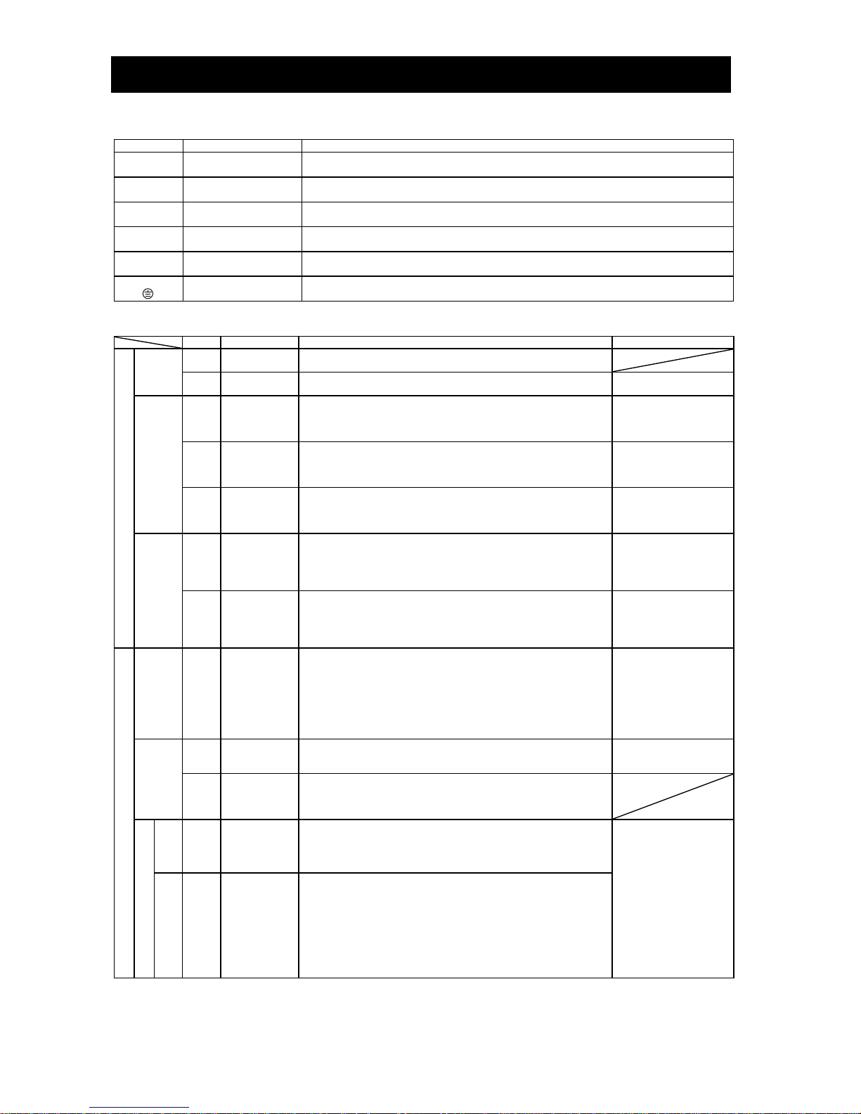
Subject
SJ700-2
SJ700D-3
Point!
Dual rating
Constant torque/
Variable torque
N/A
Selectable
If the inverter drives the light
load application (e.g. fan pump
application), you can choose
the one size smaller capacity
inverter than the motor capacity.
Easy sequence
(EzSQ) – Drive
program function
Process with 1 task.
Supporting 5 tasks
processing with
improved user
friendliness.
The inverter processes 5 tasks at
the same time, which allows you
to realize 5 times faster EzSQ
processing in maximum.
Optional LCD
Operator
SRW operator
(2-line LCD)
WOP operator
(2-line LCD)
Full compatibility with
WOP operator
(5-line LCD and
multi-language)
WOP, the optional LCD Operator,
provides several user friendliness;
- Multi data monitoring
- Parameter configuration as
monitoring data
- Multi-language display
- Parameter / Program copy
SJ700-2 to SJ700D-3:available partially
SJ700D-3 to SJ700-2:un available
RS-485 serial
communications
19.2kbps (maximum)
115.2kbps (maximum),
and so on.
Approx. 6 times faster
communication in comparison with
the former model are supported. In
addition, some communication
commands are newly supported.
Initialization
After setting b084
(initialization selection),
press some keys.
In addition to the
conventional method,
executing initialization
by a parameter is
possible.
(Select b084 and
b180=01 : enable the
initializing)
You can initialize easily only by
setting the parameter and no
special procedure is required
Phase loss
protection
Input phase loss
protection
Input phase loss
protection
Output phase loss
protection
Protection function expands to
not only input side but output side,
which provides more reliable
protection against the phase loss.

Contents
Chapter 1 Overview
1.1 Inspection of the Purchased Product ····································································································· 1 - 1
1.1.1 Inspecting the product ············································································································· 1 - 1
1.1.2 Instruction manual (this manual) ····························································································· 1 - 1
1.2 Method of Inquiry and Product Warranty ······························································································ 1 - 2
1.2.1 Method of inquiry ···················································································································· 1 - 2
1.2.2 Product warranty ····················································································································· 1 - 2
1.2.3 Warranty Terms ························································································································ 1 - 2
1.3 Exterior Views and Names of Parts ········································································································ 1 - 3
Chapter 2 Installation and Wiring
2.1 Installation ·············································································································································· 2 - 1
2.1.1 Precautions for installation ······································································································ 2 - 2
2.1.2 Backing plate ···························································································································· 2 - 4
2.2 Wiring ····················································································································································· 2 - 5
2.2.1 Terminal connection diagram and explanation of terminals and switch settings ···················· 2 - 6
2.2.2 Wiring of the main circuit ········································································································ 2 - 11
2.2.3 Wiring of the control circuit ····································································································· 2 - 20
2.2.4 Wiring of the digital operator ·································································································· 2 - 21
2.2.5 Selection and wiring of regenerative braking resistor (on 5.5 kW to 22 kW models) ··········· 2 - 22
Chapter 3 Operation
3.1 Operating Methods ································································································································ 3 - 1
3.2 How To Operate the Digital Operator (OPE-SBK) ···················································································· 3 - 3
3.2.1 Names and functions of components ···························································································· 3 - 3
3.2.2 Code display system and key operations ······················································································· 3 - 4
3.3 How To Make a Test Run ························································································································· 3 - 10
3.4 Example of I/O connections ··················································································································· 3 - 13
3.5 Basic Paramerter Setting to Drive Motor ······························································································· 3 - 17
3.5.1 Setting Frequency command source and Run command source ············································· 3 - 17
3.5.2 Frequency command source selection ···················································································· 3 - 18
3.5.3 Run command source selection ······························································································· 3 - 20
3.6 Dual rating selection(b049) ···················································································································· 3 - 22
Chapter 4 Explanation of Functions
4.1 Monitor Mode ········································································································································ 4 - 1
4.1.1 Output frequency monitoring (d001) ······················································································· 4 - 1
4.1.2 Output current monitoring (d002) ··························································································· 4 - 1
4.1.3 Rotation direction minitoring (d003) ······················································································· 4 - 1
4.1.4 Process variable (PV), PID feedback monitoring (d004, A071, A075) ······································ 4 - 1
4.1.5 Intelligent input terminal status (d005) ··················································································· 4 - 2
4.1.6 Intelligent output terminal status (d006) ················································································· 4 - 2
4.1.7 Scaled output frequency monitoring (d007, b086) ·································································· 4 - 2
4.1.8 Actual-frequency monitoring (d008, P011, H004, H204) ························································· 4 - 3
4.1.9 Torque command monitoring (d009, P033, P034) ··································································· 4 - 3
4.1.10 Torque bias monitoring (d010, P036 to P038) ········································································· 4 - 3

Contents
4.1.11 Torque monitoring (d012) ········································································································ 4 - 3
4.1.12 Output voltage monitoring (d013) ··························································································· 4 - 3
4.1.13 Power monitoring (d014) ········································································································· 4 - 3
4.1.14 Cumulative power monitoring (d015, b078, b079) ·································································· 4 - 4
4.1.15 Cumulative operation RUN time monitoring (d016) ································································ 4 - 4
4.1.16 Cumulative power-on time monitoring (d017) ········································································ 4 - 4
4.1.17 Heat sink temperature monitoring (d018) ··············································································· 4 - 4
4.1.18 Motor temperature monitoring (d019, b98) ············································································ 4 - 4
4.1.19 Life-check monitoring (d022) ··································································································· 4 - 4
4.1.20 Program counter display (easy sequence function) (d023) ······················································ 4 - 5
4.1.21 Program number monitoring (easy sequence function) (d024) ··············································· 4 - 5
4.1.22 User monitors 0 to 2 (easy sequence function)(d025 to d027) ················································ 4 - 5
4.1.23 Pulse counter monitor(d028) ··································································································· 4 - 5
4.1.24 Position command monitor (in absolute position control mode)(d029) ································· 4 - 5
4.1.25 Current position monitor (in absolute position control mode)(d030) ····································· 4 - 5
4.1.26 Inverter modemonitor (d060) ·································································································· 4 - 5
4.1.27 Trip Counter (d080) ·················································································································· 4 - 5
4.1.28 Trip monitoring 1 to 6 (d081, d082 to d086) ············································································ 4 - 6
4.1.29 Programming error monitoring (d090) ···················································································· 4 - 6
4.1.30 DC voltage monitoring (d102) ·································································································· 4 - 6
4.1.31 BRD load factor monitoring (d103, b090) ················································································ 4 - 6
4.1.32 Electronic thermal overload monitoring (d104) ······································································· 4 - 6
4.2 Function Mode ······································································································································· 4 - 7
4.2.1 Output frequency setting (F001, A001, A020, C001 to C008) ·················································· 4 - 7
4.2.2 Keypad Run key routing (F004) ································································································ 4 - 7
4.2.3 Rotational direction restriction (b035) ····················································································· 4 - 7
4.2.4 Frequency source setting (A001) ····························································································· 4 - 8
4.2.5 Run command source setting (A002, C001 to C008, C019, F004) ············································ 4 - 8
4.2.6 Stop mode selection (b091, F003, b003, b007, b088) ····························································· 4 - 9
4.2.7 STOP key enable (b087) ············································································································ 4 - 9
4.2.8 Acceleration/deceleration time setting (F002, F003, A004, P031, C001 to C008) ··················· 4 - 10
4.2.9 Base frequency setting (A003, A081, A082) ············································································· 4 - 11
4.2.10 Maximum frequency setting (A004) ························································································ 4 - 11
4.2.11 External analog input setting (O, O2, and OI) (A005, A006, C001 to C008) ····························· 4 - 12
4.2.12 Frequency operation function (A141 to A143, A001, A076) ···················································· 4 - 13
4.2.13 Frequency addition function (A145, A146, C001 to C008) ······················································· 4 - 14
4.2.14 Start/end frequency setting for external analog input (A011 to A015, A101 to A105,
A111 to A114) ·························································································································· 4 - 14
4.2.15 External analog input (O/OI/O2) filter setting (A016) ······························································ 4 - 15
4.2.16 V/f gain setting (A045, A082) ··································································································· 4 - 15
4.2.17 V/F characteristic curve selection (A044, b100, b101) ····························································· 4 - 16
4.2.18 Torque boost setting (A041, A042, A043, H003, H004)···························································· 4 - 18
4.2.19 DC braking (DB) setting (A051 to A059, C001 to C008) ···························································· 4 - 20
4.2.20 Frequency upper limit setting (A061, A062) ············································································ 4 - 24
4.2.21 Jump frequency function (A063 to A068) ················································································ 4 - 25
4.2.22 Acceleration stop frequency setting (A069, A070, A097) ························································· 4 - 25
4.2.23 PID function
(A001, A005, A071 to A076, d004, C001 to C008, C021 to C025, C044) ·································· 4 - 26
4.2.24 Two-stage acceleration/deceleration function (2CH)
(F002, F003, A092 to A096, C001 to C008) ·············································································· 4 - 30
4.2.25 Acceleration/deceleration curve selection (A097, A098, A131, A132) ···································· 4 - 31
4.2.26 Energy-saver operation (A085, A086) ······················································································ 4 - 32
4.2.27 Retry or trip after instantaneous power failure (b001 to b005, b007, b008, C021 to C026) ··· 4 - 33

Contents
4.2.28 Input/Output phase loss protection (b006 / b141,b142) ························································· 4 - 36
4.2.29 Electronic thermal protection (b012, b013, b015, b016, C021 to C026, C061) ······················· 4 - 37
4.2.30 Overload restriction/overload notice (b021 to b026, C001 to C008, C021 to C026,
C040, C041, C111) ···················································································································· 4 - 39
4.2.31 Overcurrent restraint (b027) ···································································································· 4 - 40
4.2.32 Overvoltage supression (b130 to b134) ··················································································· 4 - 41
4.2.33 Start frequency setting (b082) ································································································· 4 - 42
4.2.34 Reduced voltage start function (b036, b082) ··········································································· 4 - 42
4.2.35 Carrier frequency setting ········································································································· 4 - 43
4.2.36 Automatic carrier frequency reducation ·················································································· 4 - 44
4.2.37 Dynamic braking (BRD) function (b090, b095, b096) ······························································· 4 - 45
4.2.38 Cooling-fan operation setting (b092) ······················································································· 4 - 45
4.2.39 Intelligent input terminal setting (SET, SET3) (C001 to C008) ·················································· 4 - 46
4.2.40 Input terminal a/b (NO/NC) selection (C011 to C018, C019) ··················································· 4 - 47
4.2.41 Multispeed select setting (CF1 to CF4 and SF1 to SF7) (A019, A020 to A035,
C001 toC008) ···························································································································· 4 - 47
4.2.42 Jogging (JG) command setting (A038, A039, C001 to C008) ···················································· 4 - 49
4.2.43 2nd/3rd motor control function (SET and SET3) ······································································· 4 - 50
4.2.44 Software lock (SFT) function (b031, C001 to C008) ·································································· 4 - 51
4.2.45 Forcible-operation from digital operation (OPE) function (A001, A002,
C001 to C008) ··························································································································· 4 - 51
4.2.46 Forcible-operation from terminal (F-TM) function (A001, A002, C001 to C008) ····················· 4 - 51
4.2.47 Free-run stop (FRS) function (b088, b003, b007, b028 to b030, C001 to C008) ······················ 4 - 52
4.2.48 Commercial power source switching (CS) function (b003, b007, C001 to C008) ····················· 4 - 53
4.2.49 Reset (RS) function (b003, b007, C102, C103, C001 to C008) ·················································· 4 - 54
4.2.50 Unattended start protection (USP) function (C001 to C008) ··················································· 4 - 56
4.2.51 Remote control function (UP and DWN) (C101, C001 to C008) ··············································· 4 - 56
4.2.52 External trip (EXT) function (C001 to C008) ············································································· 4 - 57
4.2.53 3-wire interface operation function (STA, STP, and F/R) (C001 to C008) ·································· 4 - 57
4.2.54 Control gain switching function (CAS) (A044, C001 to C008, H005, H050 to H052,
H070 to H072) ·························································································································· 4 - 58
4.2.55 P/PI switching function (PPI) (A044, C001 to C008, H005, H050 to H052,
H070 to H072) ·························································································································· 4 - 58
4.2.56 Analog command holding function (AHD) (C001 to C008) ······················································· 4 - 59
4.2.57 Intelligent pulse counter (PCNT and PCC) ················································································ 4 - 59
4.2.58 Intelligent output terminal setting (C021 to C026) ·································································· 4 - 60
4.2.59 Intelligent output terminal a/b (NO/NC) selection (C031 to C036) ········································· 4 - 61
4.2.60 Running signal (RUN) (C021 to C025) ······················································································· 4 - 62
4.2.61 Frequency arrival signals (FA1, FA2, FA3, FA4, and FA5) (C021 to C025, C042,
C043, C045, C046) ···················································································································· 4 - 62
4.2.62 Running time over and power-on time over signals (RNT and ONT)
(b034, C021to C026, d016, d017)····························································································· 4 - 64
4.2.63 0 Hz speed detection signal (ZS) (A044, C021 to C025, C063)·················································· 4 - 64
4.2.64 Over-torque signal (OTQ) (A044, C021 to C025, C055 to C058) ··············································· 4 - 65
4.2.65 Alarm code output function (AC0 to AC3) (C021 to C025, C062) ············································· 4 - 65
4.2.66 Logical output signal operation function (LOG1 to LOG6) (C021 to C026,
C142 to C159) ··························································································································· 4 - 66
4.2.67 Capacitor life warning signal (WAC) (C021 to C026) ································································ 4 - 67
4.2.68 Communication line disconnection signal (NDc) (C021 to C026, C077) ··································· 4 - 67
4.2.69 Cooling-fan speed drop signal (WAF) (C021 to C026, b092 to d022) ······································· 4 - 68
4.2.70 Starting contact signal (FR) (C021 to C026) ·············································································· 4 - 68
4.2.71 Heat sink overheat warning signal (OHF) (C021 to C026, C064) ·············································· 4 - 68
4.2.72 Low-current indication (LOC) signal (C021 to C026, C038, C039) ············································· 4 - 69

Contents
4.2.73 Inverter ready signal (IRDY) (C021 to C026) ············································································· 4 - 69
4.2.74 Forward rotation signal (FWR) (C021 to C026) ········································································· 4 - 69
4.2.75 Reverse rotation signal (RVR) (C021 to C026) ·········································································· 4 - 70
4.2.76 Major failure signal (MJA) (C021 to C026) ··············································································· 4 - 70
4.2.77 Window comparators
(WCO/WCOI/WCO2) (detection of terminal disconnection: ODc/OIDc/O2Dc) ······················· 4 - 71
4.2.78 Output signal delay/hold function (C130 to C141) ·································································· 4 - 72
4.2.79 Input terminal response time ·································································································· 4 - 72
4.2.80 External thermistor function (TH) (b098, b099, C085) ····························································· 4 - 72
4.2.81 FM terminal (C027, b081) ········································································································ 4 - 73
4.2.82 AM and AMI terminals (C028, C029, C106, C108 to C110) ······················································ 4 - 74
4.2.83 Initialization setting (b084, b085) ···························································································· 4 - 75
4.2.84 Function code display restriction (b037, U001 to U012) ·························································· 4 - 76
4.2.85 Initial-screen selection (selection of the initial screen to be displayed after
power-on) (b038) ····················································································································· 4 - 78
4.2.86 Automatic user-parameter setting (b039, U001 to U012) ······················································· 4 - 79
4.2.87 Stabilization constant setting (H006) ······················································································· 4 - 79
4.2.88 Selection of operation at option board error (P001, P002) ····················································· 4 - 79
4.2.89 Optimum accel/decal operation function (A044, A085, b021, b022) ······································ 4 - 80
4.2.90 Brake control function (b120 to b127, C001 to C008, C021, C025) ·········································· 4 - 81
4.2.91 Deceleration and stopping at power failure (nonstop deceleration at instantaneous
power failure) (b050 to b054) ·································································································· 4 - 83
4.2.92 Offline auto-tuning function (H001 to H004, H030 to H034, A003, A051, A082) ···················· 4 - 85
4.2.93 Online auto-tuning function ····································································································· 4 - 87
4.2.94 Secondary resistance compensation (temperature compensation) function
(P025, b098) ····························································································································· 4 - 87
4.2.95 Motor constants selection ······································································································· 4 - 88
4.2.96 Sensorless vector control (A001, A044, F001, b040 to b044, H002 to H005,
H020 to H024,H050 to H052) ··································································································· 4 - 89
4.2.97 Sensorless vector, 0 Hz domain control (A001, A044, F001, b040 to b044,
H002 to H005, H020to H024, H050 to H052, H060, H061) ······················································ 4 - 90
4.2.98 Torque monitoring function (A044, C027 to C029, H003, H004) ············································· 4 - 91
4.2.99 Forcing function (FOC) (A044, C001 to C008)··········································································· 4 - 91
4.2.100 Torque limitation function (A044, b040 to b044, C001 to C008, C021 to C025) ······················ 4 - 92
4.2.101 Reverse Run protection function (A044, b046) ········································································ 4 - 93
4.2.102 Torque LAD stop function (A044, b040 to b045) ······································································ 4 - 94
4.2.103 High-torque multi-motor operation (A044, F001, b040 to b044, H002 to H005,
H020 to H024,H050 to H052) ··································································································· 4 - 94
4.2.104 Easy sequence function (A017, P100 to P131) ········································································· 4 - 95
4.2.105 Data read/write selection (b166) ····························································································· 4 - 95
4.3 Functions Available When the Feedback Option Board (SJ-FB) Is Mounted ·········································· 4 - 96
4.3.1 Functions requiring the SJ-FB ··································································································· 4 - 96
4.3.2 V2 control pulse setting ··········································································································· 4 - 96
4.3.3 Vector control with encoder feedback ····················································································· 4 - 97
4.3.4 Torque biasing function ············································································································ 4 - 98
4.3.5 Torque control function············································································································ 4 - 98
4.3.6 Pulse train position control mode ···························································································· 4 - 99
4.3.7 Electronic gear function(Synchronous operation) ··································································· 4 - 101
4.3.8 Motor gear ratio setting function····························································································· 4 - 103
4.3.9 Position biasing function ·········································································································· 4 - 103
4.3.10 Speed biasing function ············································································································· 4 - 103
4.3.11 Home search function ·············································································································· 4 - 104

Contents
4.3.12 Absolute position control mode ······························································································· 4 - 106
4.3.13 Operation in absolute position control mode ·········································································· 4 - 107
4.3.14 Multistage position switching function (CP1/CP2/CP3) ···························································· 4 - 108
4.3.15 Speed/position switching function (SPD) ················································································· 4 - 108
4.3.16 Zero-return function ················································································································ 4 - 109
4.3.17 Forward/reverse drive stop function (FOT/ROT) ······································································ 4 - 110
4.3.18 Position range specification function ······················································································· 4 - 110
4.3.19 Teaching function ····················································································································· 4 - 110
4.3.20 Servo-on function····················································································································· 4 - 111
4.3.21 Pulse train frequency input ······································································································ 4 - 112
4.4 Communication Functions ······················································································································ 4 - 113
4.4.1 Communication in ASCII mode ································································································· 4 - 116
4.4.2 Communication in Modbus-RTU mode ···················································································· 4 - 129
Chapter 5 Error Codes
5.1 Error Codes and Troubleshooting ··········································································································· 5 - 1
5.1.1 Error codes ······························································································································· 5 - 1
5.1.2 Option boards error codes ······································································································· 5 - 5
5.1.3 Trip conditions monitoring ······································································································· 5 - 9
5.2 Warning Codes ······································································································································· 5 - 10
Chapter 6 Maintenance and Inspection
6.1 Precautions for Maintenance and Inspection ························································································ 6 - 1
6.1.1 Daily inspection ························································································································ 6 - 1
6.1.2 Cleaning ···································································································································· 6 - 1
6.1.3 Periodic inspection ··················································································································· 6 - 1
6.2 Daily and Periodic Inspections················································································································ 6 - 2
6.3 Ground Resistance Test with a Megger ·································································································· 6 - 3
6.4 Withstand Voltage Test··························································································································· 6 - 3
6.5 Method of Checking the Inverter and Converter Circuits······································································· 6 - 4
6.6 DC-Bus Capacitor Life Curve ··················································································································· 6 - 5
6.7 Output of Life Warning ··························································································································· 6 - 5
6.8 Methods of Measuring the Input/Output Voltages, Current, and Power··············································· 6 - 6
Chapter 7 Specification
7.1 Specifications ·········································································································································· 7 - 1
7.2 External dimensions ······························································································································· 7 - 4
Chapter 8 List of Data Settings
8.1 Precautions for Data Setting ··················································································································· 8 - 1
8.2 Monitoring Mode ··································································································································· 8 - 1
8.3 Function Mode ······································································································································· 8 - 2
8.4 Extended Function Mode ······················································································································· 8 - 3

Contents
Appendix
Appendix ··························································································································································· A - 1
Index
Index ································································ ·······················································Index - 1

Chapter 1 Overview
This chapter describes the inspection of the purchased product, the product warranty, and the
names of parts.
1.1 Inspection of the Purchased Product ········· 1 - 1
1.2 Method of Inquiry and Product Warranty · 1 - 2
1.3 Exterior Views and Names of Parts ············ 1 - 3
Chapter 1 Overview
1-1
1.1 Inspection of the Purchased Product
1.1.1 Inspecting the product
After unpacking, inspect the product as described below.
If you find the product is abnormal or defective, contact your supplier or local Hitachi Distributor.
(1) Check the product for damage (including falling of parts and dents in the inverter body) caused during
transportation.
(2) Check that the product package contains an inverter set, this Quick Reference Guide and a CD (including the
SJ700D-3 Instruction Manual).
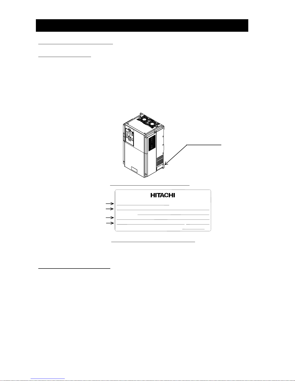
(3) Check the specification label to confirm that the product is the one you have ordered.
1.1.2 Instruction Manual (this manual)
This manual describes how to handle and maintain the Hitachi SJ700D-3 Series Inverter. Read these manuals carefully
before using the inverter, and then keep it handy for those who operate, maintain, and inspect the inverter. When
using the inverter together with optional products, also read the manuals for those products.
Note that these manuals and the manual for each optional product to be used should be delivered to the end user
of the inverter.
Specification label
Figure 1 Location of the specifications label
Figure 1-2 Contents of the specifications label
Inverter model
Input ratings
Output ratings
Serial number
Model: SJ700D-150HFF3
50Hz,60Hz 380-480V 3 Ph 35/41A
Output/Sortie: 0 - 400Hz 380-480V 3 Ph 32/37A
Input/Entree: 50Hz,60Hz V 1 Ph A
MFGNo. 44A T12345AA 001 Date: 1404
Hitachi Industrial Equipment
Systems Co.,Ltd.
MADE IN JAPAN
NE18238-29
INVERTER

Chapter 1 Overview
1-2
1.2 Method of Inquiry and Product Warranty
1.2.1 Method of inquiry
For an inquiry about product damage or faults or a question about the product, notify your supplier of
the following information:
(1) Model of your inverter
(2) Serial number (MFG No.)
(3) Date of purchase
(4) Content of inquiry
- Location and condition of damage
- Content of your question
1.2.2 Product warranty
The product will be warranted under the term described in the next section “1.2.3 Warranty Terms”.
Even within the warranty period, repair of a product fault will not be covered by the warranty (but the repair will be at
your own cost) if:
(1) the fault has resulted from incorrect usage not conforming to the instructions given in this Instruction Manual or
the repair or modification of the product carried out by an unqualified person,
(2) the fault has resulted from a cause not attributable to the delivered product,
(3) the fault has resulted from use beyond the limits of the product specifications, or
(4) the fault has resulted from disaster or other unavoidable events.
The warranty will only apply to the delivered inverter and excludes all damage to other equipment and facilities
induced by any fault of the inverter.
Repair at the user's charge :
Following the warranty period, any examination and repair of the product will be accepted at your charge. Even during
the warranty period, examination and repairs of faults, subject to the above scope of the warranty disclaimer, will be
available at charge. To request a repair at your charge, contact your supplier or local Hitachi Distributor.
1.2.3 Warranty Terms
The warranty period under normal installation and handling conditions shall be two (2) years from the date of
manufacture (“DATE” on product nameplate), or one (1) year from the date of installation, whichever occurs first. The
warranty shall cover the repair or replacement, at Hitachi’s sole discretion, of ONLY the inverter that was installed.
(1) Service in the following cases, even within the warranty period, shall be charged to the purchaser:
a. Malfunction or damage caused by mis-operation or modification or improper repair
b. Malfunction or damage caused by a drop after purchase and transportation
c. Malfunction or damage caused by fire, earthquake, flood, lightening, abnormal input voltage,
contamination, or other natural disasters
(2) When service is required for the product at your work site, all expenses associated with field repair shall be
charged to the purchaser.
(3) Always keep this manual handy; please do not lose it. Please contact your Hitachi distributor to purchase
replacement or additional manuals.
Chapter 1 Overview
1-3
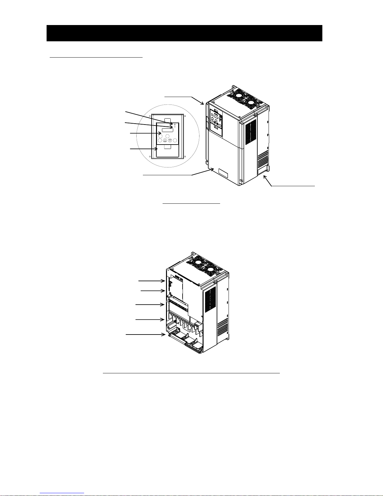
1.3 Exterior Views and Names of Parts
The figure below shows an exterior view of the inverter.
Exterior view of inverter
For the wiring of the main circuit and control circuit terminals, open the terminal block cover.
For mounting optional circuit boards, open the front cover.
Exterior view of inverter with the removed front and terminal block covers
Option slot 1
Main circuit terminals
Backing plate
Control circuit terminals
Option slot 2
POWER lamp
ALARM lamp
Digital operator
Spacer cover
Specification label
Terminal block cover
Front cover

Chapter 2 Installation and Wiring
This chapter describes how to install the inverter and the wiring of main circuit and control signal
terminals with typical examples of wiring.
2.1 Installation ·················································· 2 - 1
2.2 Wiring ························································· 2 - 5

Chapter 2 Installation and Wiring
2-1
2.1 Installation
CAUTION
- Install the inverter on a non-flammable surface, e.g., metal. Otherwise, you run the risk of fire.
- Do not place flammable materials near the installed inverter. Otherwise, you run the risk of fire.
- When carrying the inverter, do not hold its top cover. Otherwise, you run the risk of injury by dropping the
inverter.
- Prevent foreign matter (e.g., cut pieces of wire, sputtering welding materials, iron chips, wire, and dust) from
entering the inverter. Otherwise, you run the risk of fire.
- Install the inverter on a structure able to bear the weight specified in this Instruction Manual. Otherwise, you
run the risk of injury due to the inverter falling.
- Install the inverter on a vertical wall that is free of vibrations. Otherwise, you run the risk of injury due to the
inverter falling.
- Do not install and operate the inverter if it is damaged or its parts are missing. Otherwise, you run the risk of
injury.
- Install the inverter in a well-ventilated indoor site not exposed to direct sunlight. Avoid places where the
inverter is exposed to high temperature, high humidity, condensation, dust, explosive gases, corrosive gases,
flammable gases, grinding fluid mist, or salt water. Otherwise, you run the risk of fire.
- The inverter is precision equipment. Do not allow it to fall or be subject to high impacts, step on it, or place a
heavy load on it. Doing so may cause the inverter to fail.
Chapter 2 Installation and Wiring
2-2
2.1.1 Precautions for installation
(1) Transportation
The inverter uses plastic parts. When carrying the inverter, handle it carefully to prevent damage to the parts.
Do not carry the inverter by holding the front or terminal block cover. Doing so may cause the inverter to fall.
Do not install and operate the inverter if it is damaged or its parts are missing.
(2) Surface on which to install the inverter
The inverter will reach a high temperature (up to about 150°C) during operation. Install the inverter on a vertical
wall surface made of nonflammable material (e.g., metal) to avoid the risk of fire.
Leave sufficient space around the inverter. In particular, keep sufficient distance between the inverter and other heat
sources (e.g., braking resistors and reactors) if they are installed in the vicinity.
(3) Ambient temperature
Avoid installing the inverter in a place where the ambient temperature goes above or below the allowable range
(-10°C to +50°C), as defined by the standard inverter specification.
Measure the temperature in a position about 5 cm distant from the bottom-center point of the inverter, and check
that the measured temperature is within the allowable range.
Operating the inverter at a temperature outside this range will shorten the inverter life (especially the capacitor life).
(4) Humidity
Avoid installing the inverter in a place where the relative humidity goes above or below the allowable range (20% to
90% RH), as defined by the standard inverter specification.
Avoid a place where the inverter is subject to condensation.
Condensation inside the inverter will result in short circuits and malfunctioning of electronic parts. Also avoid places
where the inverter is exposed to direct sunlight.
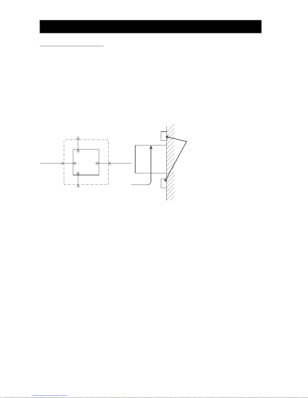
(5) Ambient air
Avoid installing the inverter in a place where the inverter is subject to dust, corrosive gases, combustible gases,
flammable gases, grinding fluid mist, or salt water.
Foreign particles or dust entering the inverter will cause it to fail. If you use the inverter in a considerably dusty
environment, install the inverter inside a totally enclosed panel.
5 cm or more
5 cm or more
(*1)
(*2)
Inverter
Keep enough clearance between the
inverter and the wiring ducts located
above and below the inverter to prevent
the latter from obstructing the
ventilation of the inverter.
(*1) 10 cm or more : up to 55kW
30cm or more : 75kW or more
(*2) 10 cm or more : up to 55kW
30cm or more : 75kW or more
But for exchanging the DC bus capacitor,
take a distance.
22cm or more : up to 55kW
30cm or more : 75kW or more
Inverter
Air flow
Wall
Chapter 2 Installation and Wiring
2-3
(6) Installation method and position
Install the inverter vertically and securely with screws or bolts on a surface that is free from vibrations and that can
bear the inverter weight. If the inverter is not installed vertically, its cooling performance may be degraded and
tripping or inverter damage may result.
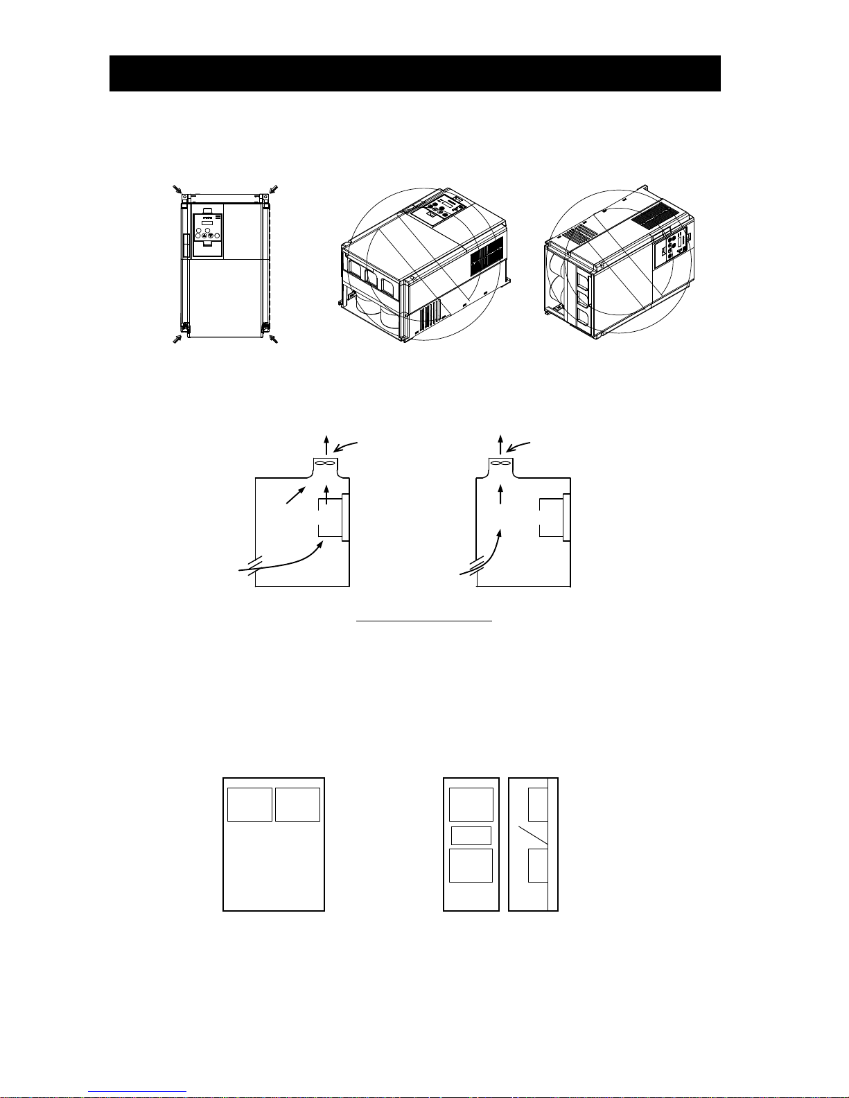
(7) When mounting multiple inverters in an enclosure with a ventilation fan, carefully design the layout of the
ventilation fan, air intake port, and inverters. An inappropriate layout will reduce the inverter-cooling effect and
raise the ambient temperature. Plan the layout so that the inverter ambient temperature will remain within the
allowable range.
Position of ventilation fan
(8) Mounting in an enclosure
The internal fan releases the heat generated by the inverter from the upper part of the inverter. When it is
necessary to install a device above the inverter, please ensure that the device is protected against this heat.
When several inverters are mounted in the same cabinet the standard arrangement of the inverters is side-by-side
with certain space as shown in the figure on the left below. If the inverters must be mounted one above the other
in order to save the cabinet space or similar, the heat from the lower inverter may lead to temperature rise and
breakdown of the higher inverter. Please ensure that the heat generated by the lower inverter does not affect the
one above by installing a mechanical separation or similar (e.g. guide plate between the inverters as shown in the
figure below right).
When mounting several inverters in the same cabinet, design the cabinet so that the temperature inside the
cabinet does not exceed the allowable specific range for the inverter (by using increased ventilation and/or
enlarging the size of cabinet etc.)
Inverter
Inverter
Enclosure
Horizontal mounting
Inverter
Inverter
Enclosure
Guide
Plate
Vertical mounting
(Unacceptable)
Ventilation fan
Inverter
(Acceptable)
Ventilation fan
Inverter
Chapter 2 Installation and Wiring
2-4
Section to be cut off
Joint
(9) Reduction of enclosure size
If you mount the inverter inside an enclosure such that the heat sink of the inverter is positioned outside the
enclosure, the amount of heat produced inside the enclosure can be reduced and likewise the size of the enclosure.
Mounting the inverter in an enclosure with the heat sink positioned outside requires an optional dedicated special
metal fitting. To mount the inverter in an enclosure with the heat sink positioned outside, cut out the enclosure
panel according to the specified cutting dimensions. The cooling section (including the heat sink) positioned
outside the enclosure has a cooling fan. Therefore, do not place the enclosure in any environment where it is
exposed to waterdrops, oil mist, or dust.
(10) Approximate loss by inverter capacity
Inverter capacity (kW)
0.4
0.75
1.5
2.2
3.7/4.0
5.5
7.5
11
15
18.5
Loss with 70% load (W)
64
76
102
127
179
242
312
435
575
698
Loss with 100% load (W)
70
88
125
160
235
325
425
600
800
975
Efficiency at rated output (%)
85.1
89.5
92.3
93.2
94.0
94.4
94.6
94.8
94.9
95.0
Inverter capacity (kW)
22
30
37
45
55
75
90
110
132/150
Loss with 70% load (W)
820
1100
1345
1625
1975
2675
3375
3900
4670
Loss with 100% load (W)
1150
1550
1900
2300
2800
3800
4800
5550
6650
Efficiency at rated output (%)
95.0
95.0
95.1
95.1
95.1
95.2
95.2
95.2
95.2
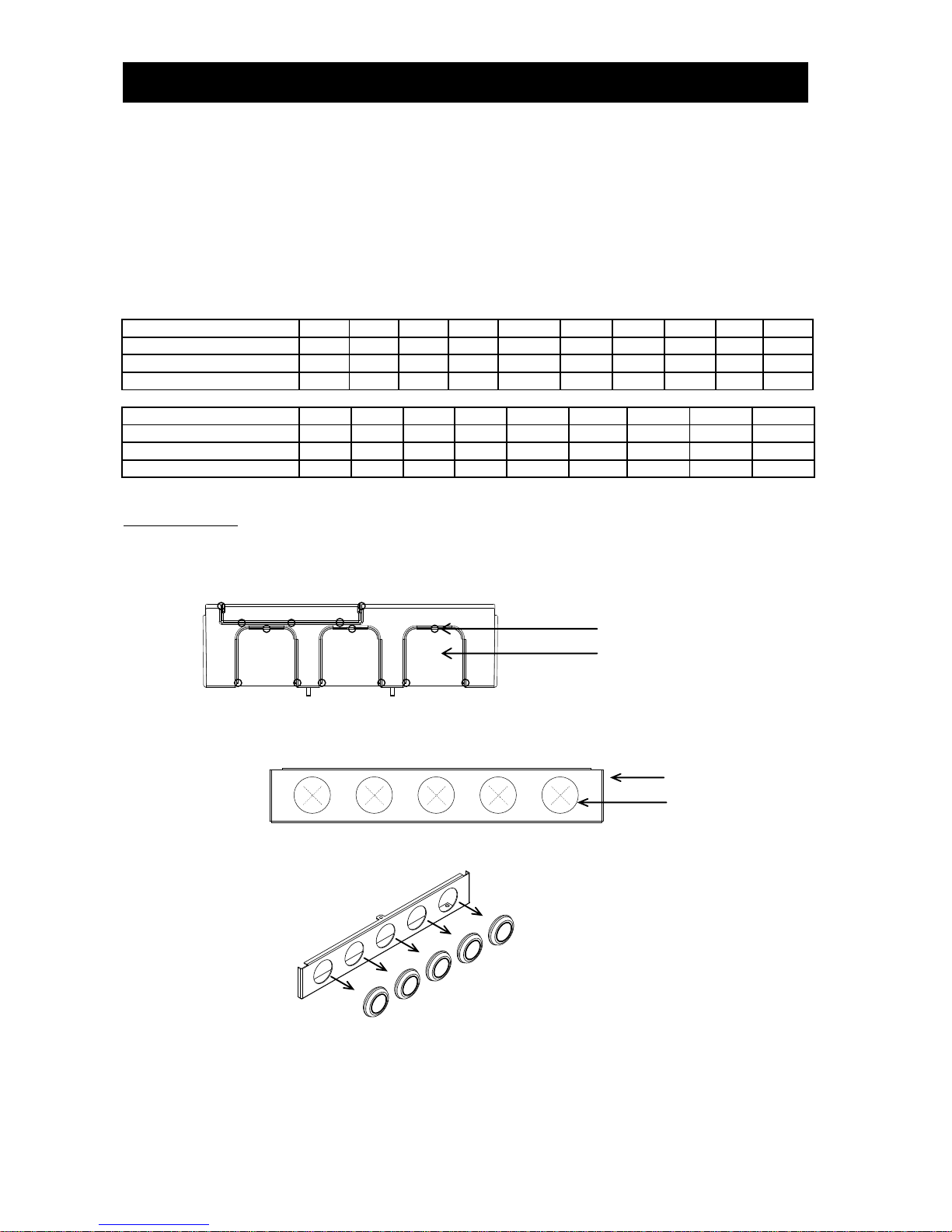
2.1.2 Backing plate
(1) For models with 30 kW or less capacity
On the backing plate, cut the joints around each section to be cut off with cutting pliers or a cutter, remove them,
and then perform the wiring.
(2) For the models with 37 kW to 75kW
1) For wiring without using conduits
Cut an X in each rubber bushing of the backing plate with cutting pliers or a cutter, and then perform the wiring.
2) For wiring using conduits
Remove the rubber bushings from the holes to be used for wiring with conduits, and then fit conduits into the
holes.
Note: Do not remove the rubber bushing from holes that are not used for wiring with a conduit.
If a cable is connected through the plate hole without a rubber bushing and conduit, the cable insulation may
be damaged by the edge of the hole, resulting in a short circuit or ground fault.
Backing plate
Rubber bushing
Chapter 2 Installation and Wiring
2-5
2.2 Wiring
WARNING
- Be sure to ground the inverter. Otherwise, you run the risk of electric shock or fire.
- Commit wiring work to a qualified electrician. Otherwise, you run the risk of electric shock or fire.
- Before wiring, make sure that the power supply is off. Otherwise, you run the risk of electric shock or fire.
- Perform wiring only after installing the inverter. Otherwise, you run the risk of electric shock or injury.
- Do not remove rubber bushings from the wiring section. Otherwise, the edges of the wiring cover may damage
the wire, resulting in a short circuit or ground fault.
CAUTION
- Make sure that the voltage of AC power supply matches the rated voltage of your inverter. Otherwise, you run
the risk of injury or fire.
- Do not input single-phase power into the inverter. Otherwise, you run the risk of fire.
- Do not connect AC power supply to any of the output terminals (U, V, and W). Otherwise, you run the risk of
injury or fire.
- Do not connect a resistor directly to any of the DC terminals (PD, P, and N). Otherwise, you run the risk of fire.
- Connect an earth-leakage breaker to the power input circuit. Otherwise, you run the risk of fire.
- Use only the power cables, earth-leakage breaker, and magnetic contactors that have the specified capacity
(ratings). Otherwise, you run the risk of fire.
- Do not use the magnetic contactor installed on the primary and secondary sides of the inverter to stop its
operation.
- Tighten each screw to the specified torque. No screws must be left loose. Otherwise, you run the risk of fire.
- Before operating, slide switch SW1 in the inverter, be sure to turn off the power supply. Otherwise, you run the
risk of electric shock and injury.
- Since the inverter supports two modes of cooling-fan operation, the inverter power is not always off, even
when the cooling fan is stopped. Therefore, be sure to confirm that the power supply is off before wiring.
Otherwise, you run the risk of electric shock and injury.
Chapter 2 Installation and Wiring
2-6
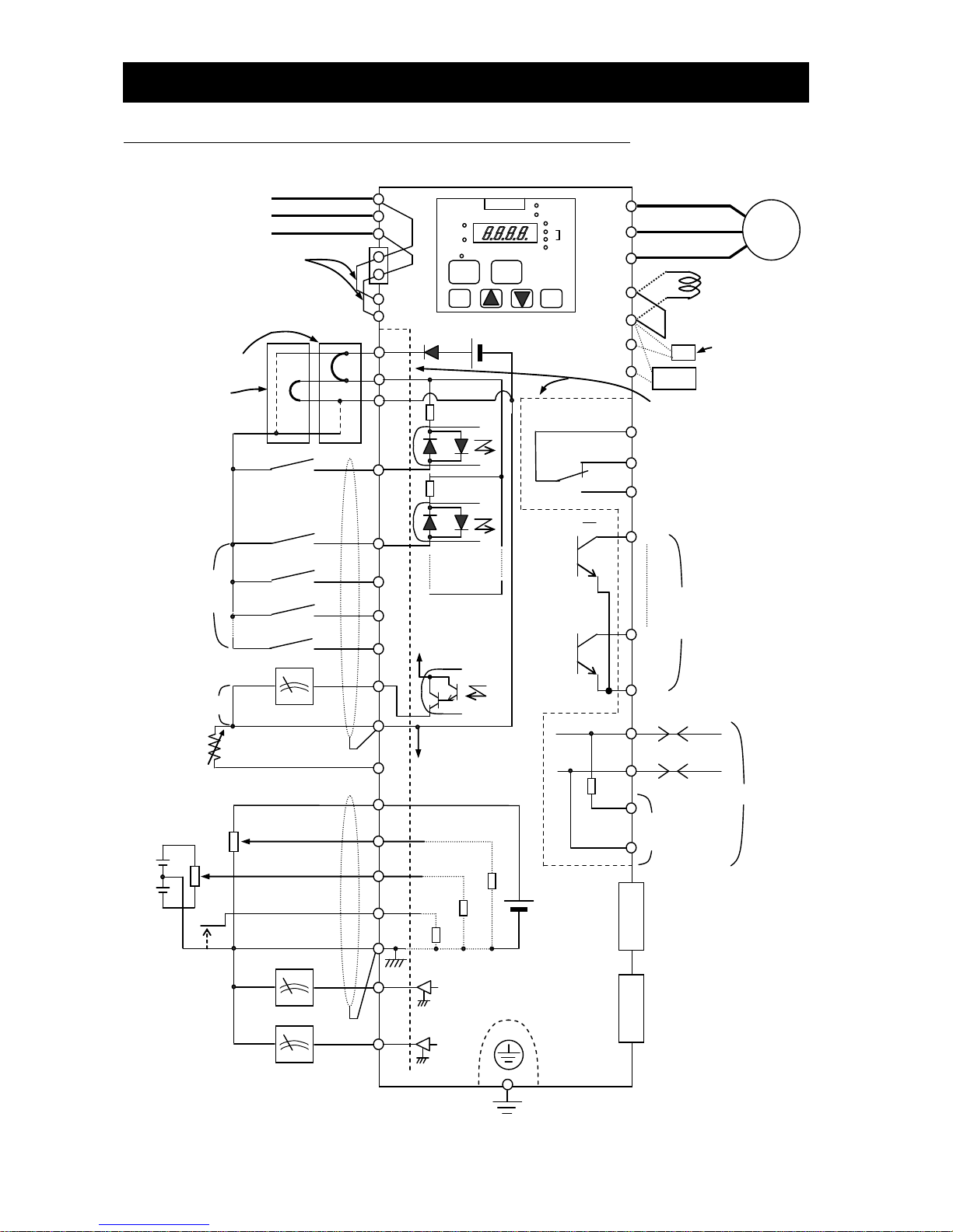
2.2.1 Terminal connection diagram and explanation of terminals and switch settings
DCL
(without jumper bar)
BRD
3-phase power supply
200 V class: 200 to 240 V +10%, -15%
(50/60 Hz ±5%)
400 V class: 380 to 480 V +10%, -15%
(50/60 Hz ±5%)
Jumper
When connecting separate
power supplies to main and
control circuits, remove J51
connector cables beforehand.
(Refer to page 2-19.)
Power supply for
control circuit
Forward rotation
command
Intelligent input
(8 contacts)
Digital monitor output
(PWM output)
Thermistor
Frequency
setting circuit
500 to 2,000Ω
0 to 10 VDC (12 bits)
-10 to +10 VDC (12 bits)
4 to 20 mA (12 bits)
Analog monitor
output
(voltage output)
Analog monitor
output
(current output)
0 to 10 V (10 bits)
4 to 20 mA (10 bits)
Motor
Jumper bar
Braking resistor
(Models with 22kW
or less capacity )
The dotted line indicates
the detachable control
terminal board.
Intelligent relay output contact
(default: alarm output)
Intelligent output
(5 terminals)
For terminating
resistor
Option 1
Option 2
Type-D grounding (for 200 V class model)
Type-C grounding (for 400 V class model)
(Refer to page 2-12.)
Default jumper position
(sinking type : FUF3/FF3)
Default jumper position
(source type : FEF3)
PLC
P24
DC24V
CM1
R S T
R0
T0 U V
W
PD
P
RB N FW 7 6 1 8
FM
CM1
H
O
O2
OI
L
AM
AMI
SP
SN
RP
SN
RS485
AL0
AL1
AL2
1
2
HITACHI
POWER
ALARM
Hz
V
A
%
kW
RUN
PRG
RUN
FUNC
STR
DC10V
100Ω
10kΩ
10kΩ
15
11
CM2
R
T
TH
J51
STOP/
RESET
M
100Ω
Chapter 2 Installation and Wiring
2-7
(1) Explanation of main circuit terminals
Symbol
Terminal name
Description
R, S, T
(L1, L2, L3)
Main power input
Connect to the AC power supply.
Leave these terminals unconnected when using a regenerative converter (HS900 series).
U, V, W
(T1, T2, T3)
Inverter output
Connect a 3-phase motor.
PD, P
(+1, +)
DC reactor connection
Remove the jumper from terminals PD and P, and connect the optional power factor reactor (DCL).
P, RB
(+, RB)
External braking resistor
connection
Connect the optional external braking resistor.
(The RB terminal is provided on models with 30 kW or less capacity.)
P, N
(+, -)
Regenerative braking unit
connection
Connect the optional regenerative braking unit (BRD).
G
Inverter ground
Connect to ground for grounding the inverter chassis by type-D grounding (for 200 V class models)
or type-C grounding (for 400 V class models).
(2) Explanation of control circuit terminals
Symbol
Terminal name
Description
Electric property
Analog
Power
supply
L
Analog power
supply (common)
This common terminal supplies po wer to frequency command termi nals (O, O2,
and OI) and analog output terminals (AM and AMI). Do not ground this terminal.
H Frequency setting
power supply
This terminal supplies 10 VDC power to the O, O2, OI terminals.
Allowable load current:
20 mA or less
Frequency setting input
O
Frequency
command
(voltage)
Input a voltage (0 to 10 VDC) as a frequency command. 10 V specifies the
maximum frequency.
To specify the maximum frequency with a voltage of 10 V or less, set the voltage
using function "A014".
Input impedance: 10kΩ
Allowable input voltages: -0.3
to +12 VDC
O2
Auxiliary
frequency
command
(voltage)
Input a voltage (0 to ±10 VDC) as a signal to be added to the frequency command
input from the O or OI terminal. You can input an independent frequency
command from this terminal (O2 terminal) alone by changing the setting.
Input impedance: 10kΩ
Allowable input voltages:
0 to 12 VDC
OI
Frequency
command
(current)
Input a current (4 to 20 mA DC) as a frequency command. 20 mA specifies the
maximum frequency.
The OI signal is valid only when the AT signal is on. Assign the AT function to an
intelligent input terminal.
Input impedance: 10kΩ
Maximum allowable current:
24 mA
Monitor output
AM
Analog monitor
(voltage)
This terminal o utputs one of the selected "0 to 10 VDC voltage output"
monitoring items. The monitoring items available for selection include output
frequency, output current, output torque (signed or unsigned), output voltage,
input power, electronic thermal overload, LAD frequency, motor temperature,
heat sink temperature, and general output.
Maximum allowable current:
2 mA
Output voltage accuracy
±20%
(Ta=25±10 degrees C)
AMI
Analog monitor
(current)
This terminal outputs one of the selec ted "4 to 20 mA DC current output"
monitoring items. The monitoring items available for selection include output
frequency, output current, output torque (unsigned), output voltage, input
power, electronic thermal overload, LAD frequency, motor temperature, heat
sink temperature, and general output.
Allowable load impedance:
250Ω or less
Output current accuracy
±20%
(Ta=25±10 degrees C)
Digital (contact)
Monitor output
FM
Digital monitor
(voltage)
This terminal outputs one of the selected "0 to 10 VDC voltage output (PWM
output mode)" monitoring items. The monitoring items available for selection
include output frequency, output current, output torque (unsigned), output
voltage, input power, e lectronic thermal overload, LAD frequency, motor
temperature, heat sink temperature, general output, digital output frequency,
and digital current monitor.
For the items "digital output frequency" and "digital current monitor," this
terminal outputs a digital pulse signal at 0/10 VDC with a duty ratio of 50%.
Maximum allowable current:
1.2 mA
Maximum frequency:
3.6 kHz
Power supply
P24
Interface power
supply
This terminal supplies 24 VDC power for contact input signals.
If the source logic is selected, this terminal is used as a common contact input
terminal.
Maximum allowable output
current: 100 mA
CM1
Interface power
supply (common)
This common terminal supplies power to the interface power supply (P24),
thermistor input (TH), and digital monitor (FM) terminals. If the sink logic is
selected, this terminal is used as a common contact input terminal. Do not
ground this terminal.
Contact input
Operation
command
FW
Forward rotation
command
Turn on this FW signal to start the forward rotation of the motor; turn it off to
stop forward rotation after deceleration.
[Conditions for turning
contact input on]
Voltage across input and PLC:
18 VDC or more
Input impedance between
input and PLC: 4.7kΩ
Maximum allowable voltage
across input and PLC:
27 VDC
Load current with 27 VDC
power: about 5.6 mA
Function selection and logic
switching
1
2
3
4
5
6
7
8
Intelligent input
Select eight of a total 70 functions, and assign these eight functions to terminals
1 to 8.
Note:
If the emergency stop function is used, terminals 1 and 3 are used exclusively for
the function. For details, see Item (3), “Explanation of switch “(on page 2-9).
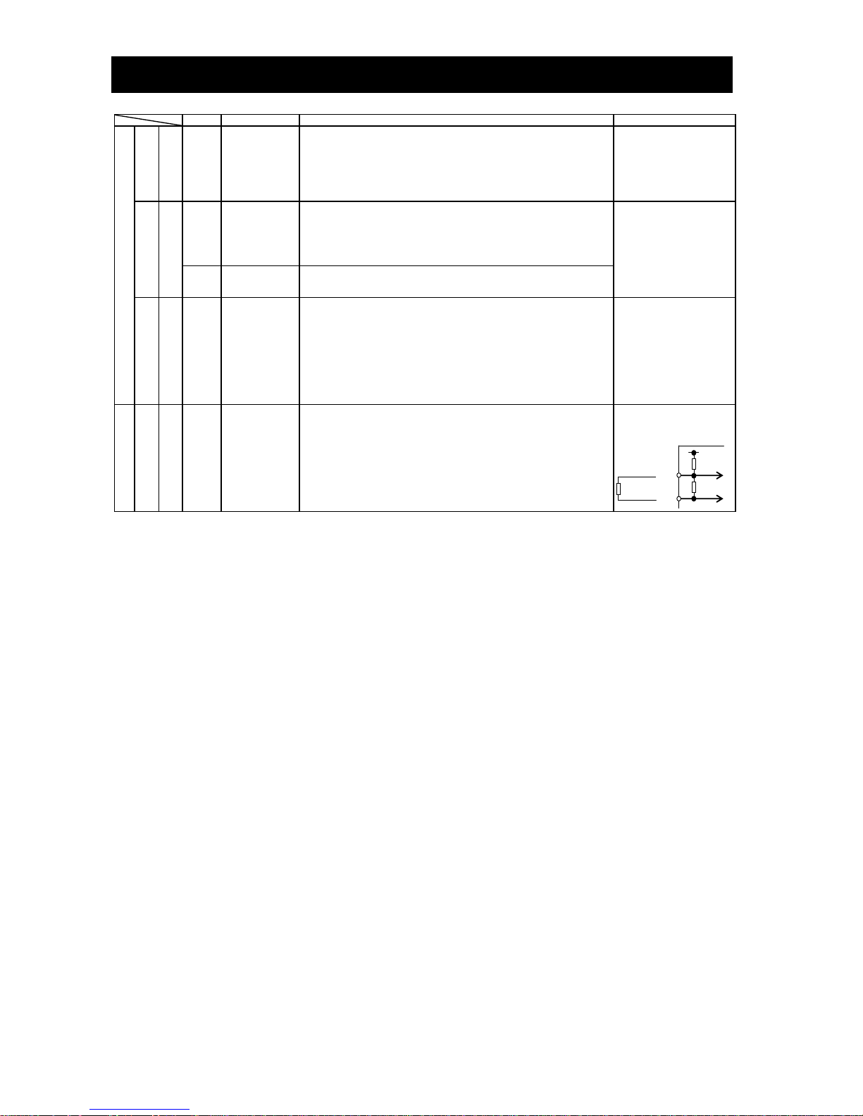
Chapter 2 Installation and Wiring
2-8
Symbol
Terminal name
Description
Electric property
Digital (contact)
Contact input
Function selection and
logic switching
PLC
Intelligent input
(common)
To switch the control logic between sink logic and source logic, change the
jumper connection of this (PLC) terminal to another terminal on the control
circuit terminal block.
Jumper terminals P24 and PLC for the sink logic; jumper terminals CM1 and PLC
for the sink logic.
To use an external power supply to drive the contact inputs, remove the jumper,
and connect the PLC terminal to the external interface circuit.
Open collector
output
Status and factor
11
12
13
14
15
Intelligent output
Select five of a total 51 functions, and assign these five functions to terminals 11
to 15.
If you have selected an alarm code using the function "C062", terminals 11 to 13
or 11 to 14 are used exclusively for the output of cause code for alarm (e.g.,
inverter trip). The control logic between each of these terminals and the CM2
terminal always follows the sink or source logic.
Voltage drop between each
terminal and CM2 when
output signal is on: 4 V or less
Maximum allowable voltage:
27 VDC
Maximum allowable current:
50 mA
CM2
Intelligent output
(common)
This terminal serves as the common terminal for intelligent output terminals [11]
to [15].
Relay contact output
Status and alarm
AL0
AL1
AL2
Intelligent relay
output
Select functions from the 51 available, and assign the selected functions to these
terminals, which serve as C contact output terminals.
In the initial setting, these terminals output an alarm indicating that the inverter
protection function has operated to stop inverter output.
(Maximum contact capacity)
AL1-AL0: 250 VAC, 2 A
(resistance) or 0.2 A
(inductive load)
AL2-AL0: 250 VAC, 1 A
(resistance) or 0.2 A
(inductive load)
(Minimum contact capacity)
100 VAC, 10 mA
5 VDC, 100 mA
Analog
Analog input
Sensor
TH
External
thermistor input
Connect to an external thermistor to make the inverter trip if an abnormal
temperature is detected.
The CM1 terminal serves as the common terminal for this terminal.
[Recommended thermistor properties]
Allowable rated power: 100 mW or more
Impedance at temperature error: 3kΩ
The impedance to detect temperature errors can be adjusted within the range 0Ω
to 9,999Ω.
Allowable range of input
voltages
0 to 8 VDC
[Input circuit]
(3) Explanation of switch
The internal slide switch (SW1) is used to enable or disable the emergency stop function (the function is disabled by
factory setting).
* For the location of the slide switch, see page 2-10.
DC8V
10kΩ
1kΩ
CM1
TH
Thermistor

Chapter 2 Installation and Wiring
2-9
About the emergency stop function (disabled by the factory setting)
- The emergency stop function shuts off the inverter output (i.e. stops the switching operation of the main circuit
elements) in response to a command from a hardware circuit via an intelligent input terminal without the operation
by internal CPU software.
Note: The emergency stop function does not electrically shut off the inverter but merely stops the switching operation
of the main circuit elements. Therefore, do not touch any terminals of the inverter or any power lines, e.g.,
motor cables. Otherwise, electric shock, injury, or ground fault may result.
- When the emergency stop function is enabled, intelligent input terminals 1 and 3 are used exclusively for this
function, and no other functions can be assigned to these terminals. Even if other functions have been assigned to
these terminals, these are automatically disabled and these terminals are used exclusively for the emergency stop
function.
Terminal [1] function:
This terminal always serves as the a (NO) contact for the reset (RS) signal.
This signal resets the inverter and releases the inverter from the trip due to emergency stop (E37.*).
Terminal [3] function:
This terminal always serves as the b (NC) contact for the emergency stop (EMR) signal.
This signal shuts off the inverter output without the operation by internal CPU software.
This signal makes the inverter trip due to emergency stop (E37.*).
Note: If intelligent input terminal 3 is left unconnected, the cable connected to the terminal is disconnected, or the
signal logic is improper, the inverter trips due to emergency stop (E37.*). If this occurs, check and correct the
wiring and signal logic, and then input the reset (RS) signal.
Only the reset (RS) signal input from intelligent input terminal [1] can release the inverter from tripping due to
emergency stop (E37.*). (The inverter cannot be released from the E37.* status by any operation from the
digital operator.)
- To enable the emergency stop function, set the slide lever of slide switch SW1 to ON. (With the factory setting, slide
switch SW1 is set to OFF to disable the function.)
Note: Before operating slide switch SW1, make sure that the input power supply is off.
Setting of slide switch SW1 setting and function selection for intelligent input terminals [1] and [3]
Setting of slide switch
SW1
Intelligent input terminal [1]
Intelligent input terminal [3]
Terminal [1] function [C001]
a/b (NO/NC) selection
[C011] (*1)
Terminal [3] function [C003]
a/b (NO/NC) selection
[C013] (*1) (*2)
SW1 is OFF.
Emergency stop
disabled
(factory setting)
Selectable arbitrarily (*4)
Selectable arbitrarily (*4)
Selectable arbitrarily (*4)
Selectable arbitrarily (*4)
Factory setting
18 (RS)
Factory setting
00 (NO)
Factory setting
06 (JG)
Factory setting
00 (NO)
SW1 is ON.
Emergency stop enabled
(*5)
Automatic assignment of functions to intelligent input terminals [1] and [3] and the terminal to which function "18 (RS)" has been
assigned (*3)
Fixed function
(cannot be
changed)
18 (RS)
Fixed function
(cannot be
changed)
00 (NO)
Fixed function
(cannot be
changed)
64 (EMR)
Fixed function
(cannot be
changed)
01 (NC)
SW1 is ON (after setting
to OFF once).
Emergency stop
disabled (*3) (*5)
Selectable arbitrarily (*4)
Selectable arbitrarily (*4)
Selectable arbitrarily (*4)
Selectable arbitrarily (*4)
Setting made
when SW1 is
set ON
retained
18 (RS)
Setting made
when SW1 is
set ON
retained
00 (NO)
Released from
emergency
stop function
no
(No function
assigned)
Setting made
when SW1 is
set ON
retained
01 (NC)
*1 When function "18 (RS)" is assigned to the input terminal, "a/b (NO/NC)" selection is always "00 (NO)".
*2 When terminal setting "C003" is "64 (EMR)", terminal setting "C013" is always "01 (NC)".
*3 If function "18 (RS)" has been assigned to an intelligent input terminal other than intelligent input terminals [1] and [3] before slide
switch SW1 is set to ON, the input terminal setting for said terminal is automatically changed to "no (no function assigned)" when slide
switch SW1 is set to ON to prevent any duplication of terminal functions. Even if slide switch SW1 is subsequently returned to OFF, the
original function setting for said terminal will not be restored. If necessary, the original function will have to be re-assigned to said
terminal.
Example: If slide switch SW1 is set to ON when function "18 (RS)" has been assigned to input terminal 2 (by terminal setting "C002"),
terminal setting "C002" is changed to "no (no function assigned)," and function "18 (RS)" is assigned to input terminal 1 (by terminal
setting "C001").
Even if slide switch SW1 is subsequently returned to OFF, terminal [2] function "C002" and terminal [1] function "C001" will remain as
"no (no function assigned)" and "18 (RS)," respectively.

Chapter 2 Installation and Wiring
2-10
*4 Function "64 (EMR)" cannot be assigned to input terminal 3 by an operation from the digital operator. The function is automatically
assigned to the terminal when slide switch SW1 is set to ON.
*5 After slide switch SW1 has been set to ON once, function assignments to intelligent input terminals [1] and [3] are not returned to their
original assignments. If necessary, re-assign original functions to the intelligent input terminals.
Note: If the data of an optional operator (WOP, SRW or SRW-EX) is copied:
If operator data is copied to your SJ700 series inverter whose slide switch SW1 is ON from another SJ700 series
inverter whose slide switch SW1 is OFF or an SJ300 series inverter, the digital operator on your SJ700 series
inverter may display [R-ERROR COPY ROM] for a moment. This event may occur because the data on intelligent
input terminals [1] and [3] cannot be copied since, on your inverter, exclusive functions have already been
assigned to intelligent input terminals [1] and [3] due to the slide switch SW1 setting to ON. Note that other
data is copied. If this event occurs, check the settings on both copy-source and copy-destination inverters.
Note: Slide Switch 12
Some models have slide switch in the position as shown below. Default setting of this switch is at "ON"
position.
Please don't change the setting. If it is changed, inverter may trip and disabled to run.
ON
Slide switch SW1
OFF
ON
Slide lever (factory setting: OFF)
Logic board
ON
OFF
ON
Slide lever
(factory setting: ON)
Slide switch SW12
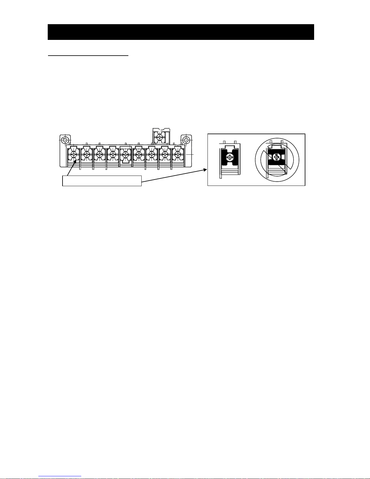
Chapter 2 Installation and Wiring
2-11
2.2.2 Wiring of the main circuit
(1) Wiring instructions
Before wiring, be sure to confirm that the Charge lamp on the inverter is turned off. When the inverter power has
been turned on once, a dangerous high voltage remains in the internal capacitors for some time after power-off,
regardless of whether the inverter has been operated. When rewiring after power-off, always wait 10 minutes or
more after power-off, and check with a multimeter that the residual voltage across terminals P and N is zero to
ensure safety during rewiring work.
(note) As for the 5.5kW and 7.5kW inverters, the washer on the main terminal screw (R, S, T, PD, P, N, U, V, W, RB)
has two cutouts. Since those cutouts are to avoid the cable fixing portion of crimp terminal goes under the
washer, it should be fixed in direction with those two cutouts in line with cable as described below.
Otherwise, you run the risk of loose connection and fire.
1) Main power input terminals (R, S, and T)
- Install an earth-leakage breaker for circuit (wiring) protection between the power supply and main power input
terminals (R, S, and T).
- Use an earth-leakage breaker with a high rating of a high-frequency sensitive current to prevent the breaker
from malfunctioning under the influence of high frequency.
- When the protective function of the inverter operates, a fault or accident may have occurred in your system.
Therefore, you are recommended to connect a magnetic contactor that interrupts the power supply to the
inverter.
- Do not use the magnetic contactor connected to the power input terminal (primary side) or power output
terminal (secondary side) of the inverter to start or stop the inverter. To start and stop inverter operation by
external signals, use only the operation commands (FW and RV signals) that are input via control circuit
terminals.
- This inverter does not support a single-phase input but supports only a three-phase input.
If you need to use a single-phase power input, contact your supplier or local Hitachi Distributor.
- Do not operate the inverter when an input phase is lost (input phase loss), otherwise the inverter may be
damaged. Since the factory setting of the inverter disables the phase loss input protection, the inverter will go
into the following status if a phase of power supply input is interrupted and not supplied to the inverter:
R or T phase interrupted: The inverter does not power up.
S phase interrupted: The inverter goes into single-phase operation, and may trip because of insufficient
voltage or overcurrent, or be damaged.
Internal capacitors remain charged, even when the power input is under a phase loss condition. Therefore,
touching an internal part may result in electric shock and injury.
When rewiring the main circuit, follow the instructions given in Item (1), "Wiring instructions."
- Carefully note that the internal converter module of the inverter may be damaged if:
- The imbalance of power voltage is 3% or more,
- The power supply capacity is at least 10 times as high as the inverter capacity and 500 kVA or more, or
- The power voltage changes rapidly.
Example: The above conditions may occur when multiple inverters are connected to each other by a short bus
line or your system includes a phase-advanced capacitor that is turned on and off during operation.
- Do not turn the inverter power on and off more often than once every 3 minutes. Otherwise, the inverter may
be damaged.
washer of the terminal screw

Chapter 2 Installation and Wiring
2-12
2) Inverter output terminals (U, V, and W)
- Use a cable thicker than the specified applicable cable for the wiring of output terminals to prevent the output
voltage between the inverter and motor dropping. Especially at low frequency output, a voltage drop due to
cable will cause the motor torque to decrease.
- Do not connect a phase-advanced capacitor or surge absorber on the output side of the inverter. If connected,
the inverter may trip or the phase-advanced capacitor or surge absorber may be damaged.
- If the cable length between the inverter and motor exceeds 20 m (especially in the case of 400 V class models),
the stray capacitance and inductance of the cable may cause a surge voltage at motor terminals, resulting in a
motor burnout. A special filter to suppress the surge voltage is available. If you need this filter, contact your
supplier or local Hitachi Distributor.
- When connecting multiple motors to the inverter, connect a thermal relay to the inverter output circuit for each
motor.
- The RC rating of the thermal relay must be 1.1 times as high as the rated current of the motor. The thermal relay
may go off too early, depending on the cable length. If this occurs, connect an AC reactor to the output of the
inverter.
3) DC reactor connection terminals (PD and P)
- Use these terminals to connect the optional DC power factor reactor (DCL). As the factory setting, terminals P
and PD are connected by a jumper. Remove this to connect the DCL.
- The cable length between the inverter and DCL must be 5 m or less.
Remove the jumper only when connecting the DCL. If the jumper is removed and the DCL is not
connected, power is not supplied to the main circuit of the inverter, and the inverter cannot operate.
4) External braking resistor connection terminals (P and RB) and regenerative braking unit connection terminals
(P and N)
- Inverter models with 22 kW or less capacity have a built-in regenerative braking (BRD) circuit. If you need
increased braking performance, connect an optional external braking resistor to terminals P and RB. Do not
connect an external braking resistor with resistance less than the specified value. Such a resistor may cause
damage to the regenerative braking (BRD) circuit.
- Inverter models with capacity of 30 kW or more do not have a built-in regenerative braking (BRD) circuit.
Increasing the braking performance of these models requires an optional regenerative braking unit and an
external braking resistor. Connect the P and N terminals of the optional regenerative braking unit to the P and N
terminals of the inverters.
- The cable length between the inverter and optional regenerative braking unit must be 5 m or less, and the two
cables must be twisted for wiring.
- Do not use these terminals for connecting any devices other than the optional external braking resistor and
regenerative braking unit.
5) Inverter ground terminal (G )
- Be sure to ground the inverter and motor to prevent electric shock.
- According to the Electric Apparatus Engineering Regulations, connect 200 V class models to grounding
electrodes constructed in compliance with type-D grounding (conventional type-III grounding with ground
resistance of 100Ω or less) or the 400 V class models to grounding electrodes constructed in compliance with
type-C grounding (conventional special type-III grounding with ground resistance of 10Ω or less).
- Use a grounding cable thicker than the specified applicable cable, and make the ground wiring as short as
possible.
- When grounding multiple inverters, avoid a multi-drop connection of the grounding route and formation of a
ground loop, otherwise the inverter may malfunction.
Inverter
Inverter
Inverter
Grounding bolt
prepared by user
Inverter
Inverter
Inverter

Chapter 2 Installation and Wiring
2-13
(2) Layout of main circuit terminals
The figures below show the terminal layout on the main circuit terminal block of the inverter.
Terminal layout
Inverter model
SJ700D-004 to 037L
FF3/FEF3/FUF3
SJ700D-007 to 040H
FF3/FEF3/FUF3
R0 and T0 : M4
Ground terminal : M4
Other terminals : M4
Enabling PIN(J61)
Disabling PIN(J62)
EMC filter disables
(factory setting)
Dummy plug (green)
Short plug
EMC filter enables
Short plug
Dummy plug (green)
If you need to activate the
EMC filter, you need to set
the dummy plug and the
short plug in reference to
below list appropriately.
Note:
Before setting the plugs,
make sure that the power
supply is off. Otherwise, you
run the risk of electric shock.
You need to set the plugs
before power supply to the
inverter.
Dummy plug (green)
Enabling PIN(J61)
Short plug
Disabling PIN(J62)
[Method of enabling/disabling the EMC filter function]
R
(L1)
S
(L2) T (L3)
PD
(+1)
P
(+)
N U (T1)
V
(T2) W (T3)
R0
T0
Charge lamp
Jumper connecting terminals PD and P
When not using the DCL,
do not remove the jumper
from terminals PD and P.
G
G
RB
(-)

Chapter 2 Installation and Wiring
2-14
Terminal layout
Inverter model
SJ700D-055, 075L
FF3/FEF3/FUF3
SJ700D-055, 075H
FF3/FEF3/FUF3
R0 and T0 : M4
Ground terminal : M5
Other terminals : M5
SJ700D-110LFF3/FEF3/FUF3
SJ700D-110HFF3/FEF3/FUF3
R0 and T0 : M4
Ground terminal : M5
Other terminals : M5
SJ700D-150 to 185L
FF3/FEF3/FUF3
SJ700D-150 to 220H
FF3/FEF3/FUF3
R0 and T0 : M4
Ground terminal : M6
Other terminals : M6
SJ700D-220L
FF3/FEF3/FUF3
R0 and T0 : M4
Ground terminal : M6
Other terminals : M8
[Method of enabling/disabling the EMC filter function]
Enabling the EMC filter
Disabling the EMC filter
(factory setting)
Disabling the EMC filter
(factory setting)
[Method of enabling/disabling the EMC filter function]
Enabling the EMC filter
R
(L1)
S
(L2) T (L3)
PD
(+1)
P
(+)
N U (T1) V (T2) W (T3)
Charge lamp
Jumper connecting
terminals PD and P
When not using the DCL,
do not remove the jumper
from terminals PD and P.
G
G
RB
(-)
R0
T0
Ground terminal with jumper (shaded in the figure) to
enable/disable the EMC filter function
R
(L1) S (L2) T (L3)
PD
(+1)
P
(+)
N
U
(T1)
V
(T2) W (T3)
Charge lamp
Jumper connecting
terminals PD and P
When not using the DCL,
do not remove the jumper
from terminals PD and P.
G
G
RB
(-)
R0
T0
Ground terminal with jumper (shaded in the figure)
to enable/disable the EMC filter function.

Chapter 2 Installation and Wiring
2-15
Terminal layout
Inverter model
SJ700D-300L
FF3/FEF3/FUF3
R0 and T0 : M4
Ground terminal : M6
Other terminals : M8
SJ700D-300H
FF3/FEF3/FUF3
R0 and T0 : M4
Ground terminal : M6
Other terminals : M8
SJ700D-370L
FF3/FEF3/FUF3
SJ700D-370H
FF3/FEF3/FUF3
R0 and T0 : M4
Ground terminal : M6
Other terminals : M8
SJ700D-450L
FF3/FEF3/FUF3
SJ700D-450H, 550H
FF3/FEF3/FUF3
R0 and T0 : M4
Ground terminal : M8
Other terminals : M8
[Method of enabling/disabling the EMC filter function]
Enabling the EMC filter
Disabling the EMC filter
(factory setting)
[Method of enabling/disabling the EMC filter function]
Enabling the EMC filter
Disabling the EMC filter
(factory setting )
R
(L1)
S
(L2)
T
(L3)
PD
(+1)
P
(+)
N U (T1) V (T2) W (T3)
Charge lamp
Jumper connecting
terminals PD and P
G
G
(-)
R0
T0
Ground terminal with jumper (shaded in the figure) to
enable/disable the EMC filter function
When not using the DCL,
do not remove the jumper
from terminals PD and P.
G
R
(L1)
S
(L2) T (L3)
PD
(+1)
P
(+)
N U (T1) V (T2) W (T3)
Charge lamp
Jumper connecting
terminals PD and P
G
G
(-)
R0
T0
Ground terminal with jumper (shaded in the figure) to
enable/disable the EMC filter function
When not using the DCL,
do not remove the jumper
from terminals PD and P.

Chapter 2 Installation and Wiring
2-16
Terminal layout
Inverter model
SJ700D-550L
FF3/FEF3/FUF3
R0 and T0 : M4
Ground terminal : M8
Other terminals : M10
SJ700D-750 to 1100H
FF3/FEF3/FUF3
SJ700D-1320HFF3/FEF3
SJ700D-1500HFUF3
R0 and T0 : M4
Ground terminal : M8
Other terminals : M10
Reference: Leakage current by inverter with model EMC filter enabled or disabled (reference data). The table below lists the reference currents that
may leak from the inverter when the internal EMC filter is enabled or disabled. (Leakage current is in proportion to the voltage and frequency of
input power.) Note that the values listed in the table below indicate the reference currents leaking from the inverter alone. The values exclude
current leakage from external devices and equipment (e.g., power cables). The drive in the range from 75kW to 150kW doesn't have the switch to
activate and deactivate the internal EMC filter. They complies EMC directive C3 level in standard condition.
200 V class model (input power: 200 VAC, 50 Hz)
400 V class model (input power: 400 VAC, 50 Hz)
0.4kW
to 3.7kW
5.5kW
to 11kW
15kW
to 37kW
45kW
to 55kW
0.75kW
to 3.7kW
5.5kW
to11kW
15kW
to 37kW
45kW
to 55kW
75kW to
150kW
Internal EMC filter enabled
Ca. 2.5mA
Ca. 48mA
Ca. 23mA
Ca. 23mA
Ca. 5mA
Ca. 95mA
Ca 56mA
Ca 56mA
-
Internal EMC filter disabled
Ca. 0.1mA
Ca. 0.1mA
Ca. 0.1mA
Ca. 0.1mA
Ca. 0.2mA
Ca. 0.2mA
Ca 0.2mA
Ca. 0.2mA
Ca. 0.2mA
[Method of enabling/disabling the EMC filter function]
Enabling the EMC filter
Disabling the EMC filter
(factory setting)
R
(L1) S (L2) T (L3)
PD
(+1) P (+) N (-) U (T1) V (T2) W (T3)
R0
T0
Jumper connecting terminals
PD and P
Charge lump
R
(L1)
S
(L2)
T
(L3)
PD
(+1) P (+) N U
(T1) V (T2) W (T3)
Charge lamp
Jumper connecting
terminals PD and P
G
G
(-)
Ground terminal with jumper (shaded in the figure)
to enable/disable the EMC filter function
When not using the DCL,
do not remove the jumper
from terminals PD and P.
G

Chapter 2 Installation and Wiring
2-17
(3) Applicable peripheral equipment
See Item (4), "Recommended cable gauges, wiring accessories, and crimp terminals."
Note 1: The peripheral equipment described here is applicable when the inverter connects a
standard Hitachi 3-phase, 4-pole squirrel-cage motor.
Note 2: Select breakers that have proper capacity. (Use breakers that comply with inverters.)
Note 3: Use earth-leakage breakers (ELB) to ensure safety.
Note 4: Use copper electric wire (HIV cable) of which the maximum allowable temperature of the
insulation is 75°C.
Note 5: If the power line exceeds 20 m, cable that is thicker than the specified applicable cable
must be used for the power line.
Note 6: Use a 0.75 mm2 cable to connect the alarm output contact.
Note 7: T ighten each terminal screw with the specified tightening torque. Loose terminal screws
may cause short circuits and fire. Tightening a terminal screw with excessive torque may
cause damage to the terminal block or inverter body.
Note 8: Select an earth-leakage breaker (ELCB) of which the rated sensitivity current matches the
total length of cables connected between the inverter and power supply and between the
inverter and motor. Do not use a high-speed type ELB but use a delayed-type ELB because
the high-speed type may malfunction.
Note 9: When a CV cable is used for wiring through a metal conduit, the average current leakage
is 30 mA/km.
Note 10: When an IV cable, which has a high relative dielectric constant, is used, the leakage
current is about eight times as high as the standard cable. Therefore, when using an IV
cable, use the ELB of which the rated sensitivity current is eight times as high as that given
in the table below. If the total cable length exceeds 100 m, use a CV cable.
Total cable length
Sensitivity current (mA)
100 m or less
50
300 m or less
100
Name
Description
Reactor on input side (for harmonic
control, power supply coordination,
and power factor improvement)
(ALI-XXX)
Use this reactor to control harmonic waves or when the imbalance of power
supply voltage is 3% or more, when the power supply capacity is 500 kVA or
more, or when the power voltage may change rapidly. This reactor also
improves the power factor.
Noise filter for inverter
(NF-XXX)
This noise filter reduces the conductive noise that is generated by the
inverter and transmitted in cables. Connect this noise filter to the primary
side (input side) of the inverter.
Radio noise filter
(Zero-phase reactor) (ZCL-X)
The inverter may generate radio noise through power supply wiring during
operation. Use this noise filter to reduce the radio noise (radiant noise).
Radio noise filter on input side
(Capacitor filter) (CFI-X)
Use this noise filter to reduce the radiant noise radiated from input cables.
DC reactor (DCL-X-XX)
Use this reactor to control the harmonic waves generated by the inverter.
Braking resistor
Regenerative braking unit
Use these devices to increase the braking torque of the inverter for operation
in which the inverter turns the connected load on and off very frequently or
decelerates the load running with a high moment of inertia.
Noise filter on the output side
(ACF-CX)
Connect this noise filter between the inverter and motor to reduce the
radiant noise radiated from cables for the purpose of reducing the
electromagnetic interference with radio and television reception and
preventing malfunctions of measuring equipment and sensors.
Radio noise filter
(Zero-phase reactor)
(ZCL-XXX)
Use this noise filter to reduce the noise generated on the output side of the
inverter. (This noise filter can be used on both the input and output sides.)
AC reactor for the output side
For reducing vibrations and
preventing thermal relay malfunction
(ACL-X-XX)
Using the inverter to drive a general-purpose motor may cause larger
vibrations of the motor when compared with driving it directly with the
commercial power supply. Connect this AC reactor between the inverter and
motor to lessen the pulsation of motor. Also, connect this AC reactor
between the inverter and motor, when the cable length between them is
long (10 m or more), to prevent thermal relay malfunction due to the
harmonic waves that are generated by the switching operation on the
inverter. Note that the thermal relay can be replaced with a current sensor to
avoid the malfunction.
LCR filter
Connect this noise filter between the inverter and motor to convert the
inverter output into a sinusoidal waveform and to reduce the motor
vibration, motor noise and the radiant noise radiated from cables.
R S T
R0
T0
Inverter
Power
supply
ELCB
Magnetic
contactor
U V W
PD
P
N
Motor
M
RB

Chapter 2 Installation and Wiring
2-18
(4) Recommended cable gauges, wiring accessories, and crimp terminals
Note: For compliance with CE and UL standards, see the safety precautions concerning EMC and the compliance
with UL and cUL standards under Safety Instructions.
The table below lists the specifications of cables, crimp terminals, and terminal screw tightening torques for
reference.
Note: Cable gauges indicate those of HIV cables (maximum heat resistance: 75°C).
Note: *** is described as FF, FEF or FUF.
Note: Please use the round type crimp terminals (for the UL standard) suitable for the use electric wire when you connect the
electric wire with the main circuit terminal stand. Please put on pressure to the crimp terminals l with a crimp tool that the
terminal stand maker recommends.
Motor
output
(kW)
Applicable inverter
model
Gauge of
power line
cable (mm2)
(Terminals: R,
S, T, U, V, W,
P, PD, and N)
Grounding
cable
(mm2)
External braking
resistor across
terminals P and
RB (mm2)
Size of
terminal
screw
Crimp
termi
nal
Tightening
torque (N-m)
Applicable device
Earth-leakage
breaker (ELB)
Magnetic
contactor
(MC)
200 V class
0.4
SJ700D-004L***3
1.25
1.25
1.25
M4
1.25-4
1.2(MAX1.8)
EX50B(5A)
HS10
0.75
SJ700D-007L***3
1.25
1.25
1.25
M4
1.25-4
1.2(MAX1.8)
EX50B(10A)
HS10
1.5
SJ700D-015L***3
2 2 2
M4
2-4
1.2(MAX1.8)
EX50B(15A)
HS10
2.2
SJ700D-022L***3
2 2 2
M4
2-4
1.2(MAX1.8)
EX50B(20A)
HS20
3.7
SJ700D-037L***3
3.5
3.5
3.5
M4
3.5-4
1.2(MAX1.8)
EX50B(30A)
HS20
5.5
SJ700D-055L***3
5.5
5.5
5.5
M5
R5.5-5
2.4(MAX4.0)
EX50B(50A)
HS25
7.5
SJ700D-075L***3
8 8 8
M5
R8-5
2.4(MAX4.0)
EX60(60A)
HS35
11
SJ700D-110L***3
14
14
14
M6
R14-6
4.0(MAX4.4)
RXK100-H(75A)
HS50
15
SJ700D-150L***3
22
22
22
M6
22-6
4.5(MAX4.9)
RXK100-H(100A)
H65C
18.5
SJ700D-185L***3
30
22
30
M6
38-6
4.5(MAX4.9)
RXK100-H(100A)
H80C
22
SJ700D-220L***3
38
30
38
M8
38-8
8.1(MAX8.8)
RXK225-H(150A)
H100C
30
SJ700D-300L***3
60(22×2)
30 ― M8
60-8
8.1(MAX8.8)
RXK225-H(200A)
H125C
37
SJ700D-370L***3
100(38×2)
38 ― M8
100-8
8.1(MAX20)
RXK225-H(225A)
H150C
45
SJ700D-450L***3
100(38×2)
38 ― M8
100-8
8.1(MAX20)
RXK225-H(225A)
H200C
55
SJ700D-550L***3
150(60×2)
60 ― M10
150-10
19.5(MAX22)
RX400B(350A)
H250C
400 V class
0.75
SJ700D-007H***3
1.25
1.25
1.25
M4
1.25-4
1.2(MAX1.8)
EX50C(5A)
HS10
1.5
SJ700D-015H***3
2 2 2
M4
2-4
1.2(MAX1.8)
EX50C(10A)
HS10
2.2
SJ700D-022H***3
2 2 2
M4
2-4
1.2(MAX1.8)
EX50C(10A)
HS10
3.7
SJ700D-037HFF3
SJ700D-037HFUF3
2 2 2
M4
2-4
1.2(MAX1.8)
EX50C(15A)
HS20
4.0
SJ700D-040HFEF3
2 2 2
M4
2-4
1.2(MAX1.8)
EX50C(15A)
HS20
5.5
SJ700D-055H***3
3.5
3.5
3.5
M5
R2-5
2.4(MAX4.0)
EX50C(30A)
HS20
7.5
SJ700D-075H***3
3.5
3.5
3.5
M5
3.5-5
2.4(MAX4.0)
EX50C(30A)
HS25
11
SJ700D-110H***3
5.5
5.5
5.5
M6
R5.5-6
4.0(MAX4.4)
EX50C(50A)
HS35
15
SJ700D-150H***3
8 8 8
M6
8-6
4.5(MAX4.9)
EX60B(60A)
HS35
18.5
SJ700D-185H***3
14
14
14
M6
14-6
4.5(MAX4.9)
EX60B(60A)
HS50
22
SJ700D-220H***3
14
14
14
M6
14-6
4.5(MAX4.9)
RXK100-H(75A)
HS50
30
SJ700D-300H***3
22
22 ― M6
22-6
4.5(MAX4.9)
RXK100-H(100A)
H65C
37
SJ700D-370H***3
38
22 ― M8
38-8
8.1(MAX20)
RXK100-H(100A)
H80C
45
SJ700D-450H***3
38
22 ― M8
38-8
8.1(MAX20)
RXK225-H(150A)
H100C
55
SJ700D-550H***3
60
30 ― M8
R60-8
8.1(MAX20)
RXK225-H(175A)
H125C
75
SJ700D-750H***3
100(38×2)
38 ― M10
100-10
20.0(MAX22)
RXK225-H(225A)
H150C
90
SJ700D-900H***3
100(38×2)
38 ― M10
100-10
20.0(MAX22)
RXK225-H(225A)
H200C
110
SJ700D-1100H***3
150(60×2)
60 ― M10
150-10
20.0(MAX35)
RX400B(350A)
H250C
132
SJ700D-1320HFF3
SJ700D-1320HFEF3
80×2
80 ― M10
80-10
20.0(MAX35)
RX400B(350A)
H300C
150
SJ700D-1500HFUF3
80×2
80 ― M10
80-10
20.0(MAX35)
RX400B(350A)
H300C

Chapter 2 Installation and Wiring
2-19
(5) Connecting the control circuit to a power supply separately from the main circuit.
If the protective circuit of the inverter operates to open the magnetic contactor in the input power supply circuit,
the inverter control circuit power is lost, and the alarm signal cannot be retained. To retain the alarm signal,
connect control circuit terminals R0 and T0 to a power supply. In details, connect the control circuit power supply
terminals R0 and T0 to the primary side of the magnetic contactor as shown below.
(Connection method)
Power-receiving specifications
200 V class model:
200 to 240 V (+10%, -15%)
(50/60 Hz ±5%), (282 to 339 VDC)
400 V class model:
380 to 480 V (+10%, -15%)
(50/60 Hz ±5%), (537 to 678 VDC)
Note the following when connecting separate power supplies to control circuit power supply terminals (R0 and T0) and main
circuit power supply terminals (R, S, and T):
- Use a cable thicker than 1.25 mm2 to connect the terminals R0 and T0 (terminal screw size: M4).
- Connect a 3A fuse in the control circuit power supply line. (Tightening torque: 1.2Nm,max torque: 1.4Nm)
- If the control circuit power supply (connected to R0 and T0) is turned on earlier than the main circuit power supply (connected
to R, S, and T), ground fault is not checked at power-on.
- When supplying DC power to the control circuit power supply terminals (R0 and T0), specify "00" as the "a/b (NO/NC)"
selection (function code C031 to C036) for intelligent output terminals ([11] to [15]) and intelligent relay terminals (AL0, AL1,
and AL2). If "01" is specified as the "a/b (NO/NC)" selection, output signals may chatter when the DC power supply is shut off.
2. Remove the J51 connector.
1. Remove the connected cables.
3. Connect the control circuit power
supply cables to the control circuit
power supply terminal block.
J51

Chapter 2 Installation and Wiring
2-20
2.2.3 Wiring of the control circuit
(1) Wiring instructions
1) Terminals L and CM1 are common to I/O signals and isolated from each other.
Do not connect these common terminals to each other or ground them.
Do not ground these terminals via any external devices. (Check that the external devices connected to these
terminals are not grounded.)
2) Use a shielded, twisted-pair cable (recommended gauge: 0.75 mm2) for connection to control circuit terminals,
and connect the cable insulation to the corresponding common terminal. (Tightening torque: 0.7Nm,max
torque: 0.8Nm)
3) The length of cables connected to control circuit terminals must be 20 m or less. If the cable length exceeds 20
m unavoidably, you should use UP/DOWN function or current signal input with an isolation amplifier.
4) Separate the control circuit wiring from the main circuit wiring (power line) and relay control circuit wiring.
If these wirings intersect with each other unavoidably, square them with each other. Otherwise, the inverter may
malfunction.
5) Twist the cables connected from a thermistor to the thermistor input terminal (TH) and terminal CM1, and
separate the twisted cables from other cables connected to other common terminals. Since very low current
flows through the cables connected to the thermistor, separate the cables from those (power line cables)
connected to the main circuit. The length of the cables connected to the thermistor must be 20 m or less.
6) When connecting a contact to a control circuit terminal (e.g., an intelligent input terminal), use a relay contact
(e.g., crossbar twin contact) in which even a very low current or voltage will not trigger any contact fault.
7) When connecting a relay to an intelligent output terminal, also connect a surge-absorbing diode in parallel with
the relay.
8) Do not connect analog power supply terminals H and L or interface power supply terminals P24 and CM1 to
each other. Otherwise, the inverter may fail.
(2) Layout of control circuit terminals
H O2
AM
FM
TH
FW 8 CM1 5 3 1 14
13
11
AL1
L O OI
AMI
P24
PLC
CM1 7 6 4 2
15
CM2
12
AL0
AL2
Terminal screw size: M3 (Tightening torque:0.7Nm,max torque:0.8Nm)
(3) Switching the input control logic
- In the factory setting, the input control logic for terminal FW and intelligent input terminals is the sink logic.
To switch the input control logic to the source logic, remove the jumper connecting terminals P24 and PLC on the
control circuit block, and then connect terminals PLC and CM1 with the jumper.
TH
PLC
CM1
7
6
CM1 8 FW
Thermistor
PLC
5
4

Chapter 2 Installation and Wiring
2-21
(4) Connecting a programmable controller to intelligent input terminals
When using the internal interface power supply
When using an external power supply
(Remove the jumper from the control circuit terminal block.)
Sink logic
Source logic
(5) Connecting a programmable controller to intelligent output terminals
Sink logic
Source logic
2.2.4 Wiring of the digital operator
- You can operate the inverter with not only the digital operator mounted in the inverter as standard equipment but
also an optional digital operator (OPE-S, OPE-SR, WOP).
- When you intend to remove the standard digital operator from the inverter and use it as remote equipment, request
your local Hitachi Distributor to supply a connection cable, ICS-1 (1-meter cable) or ICS-3 (3-meter cable). If you
prepare the cable by yourself, the following product is recommended:
NETSTAR-C5E PC 24AWGx4P LBH: Straight cable equipped with connector at both ends (made by Hitachi Metal, Ltd.)
- The length of the connection cable must be 3 m or less. If a cable over 3 m is used, the inverter may malfunction.
Inverter
Output module
(EH-YT**,etc.)
Jumper
S
COM
P24
PLC
CM1
FW 8 Inverter
P24
DC24V
CM1
FW
DC24V
S
COM
Output module
(EH-YTP**,etc.)
8
Inverter
Output module
(EH-YTP**,etc.)
DC24V
DC24V
COM
P24
PLC
CM1
FW 8 DC24V
Inverter
Output module
(EH-YT**,etc.)
S
COM
P24
PLC
CM1
FW
8
Jumper
11
12
CM2
COM
Inverter
Input module
(EH-XD**,etc.)
DC24V
Inverter
11
Input module
(EH-XD**,etc.)
12
CM2
COM
DC24V
DC24V
PLC

Chapter 2 Installation and Wiring
2-22
2.2.5 Selection and wiring of dynamic braking resistor (on 0.4 kW to 22 kW models)
The SJ700D-3 series inverter models with capacities of 0.4 to 22 kW have an internal dynamic braking circuit.
Connecting an optional dynamic braking resistor to RB and P terminals increases the braking torque.
Motor
capacity
(kW)
Applicable
inverter model
Without a resistor
connected
With a resistor connected
Minimum connectable
resistor
Minimum
resistance
during
continuous
operation
(Ω)
Braking torque
(%)
Resistance of
connected
resistor (Ω)
Braking torque
(%)
Resistance
(Ω)
BRD usage
rate
(%)
200V class
0.4
SJ700D-004L***3
20
48
150 over
48
10
150
0.75
SJ700D-007L***3
20
48
150 over
48
10
150
1.5
SJ700D-015L***3
20
32
150 over
32
10
100
2.2
SJ700D-022L***3
20
32
150 over
32
10
100
3.7
SJ700D-037L***3
20
32
110
32
10
100
5.5
SJ700D-055L***3
20
16
140
16
10
50
7.5
SJ700D-075L***3
20
10
150 over
10
10
50
11
SJ700D-110L***3
10
10
110
10
10
50
15
SJ700D-150L***3
10
7.5
110
7.5
10
35
18.5
SJ700D-185L***3
10
7.5
90
7.5
10
35
22
SJ700D-220L***3
10 5 110
5
10
35
400V class
0.75
SJ700D-007H***3
20
100
150 over
70
10
300
1.5
SJ700D-015H***3
20
100
150 over
70
10
300
2.2
SJ700D-022H***3
20
100
150 over
70
10
300
3.7
SJ700D-037HFF3
SJ700D-037HFUF3
20
70
150 over
70
10
200
4.0
SJ700D-040HFEF3
20
70
150 over
70
10
200
5.5
SJ700D-055H***3
20
70
130
70
10
200
7.5
SJ700D-075H***3
20
70
150 over
35
10
150
11
SJ700D-110H***3
10
50
130
35
10
150
15
SJ700D-150H***3
10
35
140
24
10
100
18.5
SJ700D-185H***3
10
35
140
24
10
100
22
SJ700D-220H***3
10
35
110
20
10
100
Note: *** is described as FF, FEF or FUF.

Chapter 2 Installation and Wiring
2-23
(Memo)

Chapter 3 Operation
This chapter describes typical methods of operating the inverter, how to operate the digital
operator, and how to make a test run of the inverter.
3.1 Operating Methods ······················································· 3 - 1
3.2 How To Operate the Digital Operator (OPE-SBK) ·········· 3 - 3
3.3 How To Make a Test Run ··············································· 3 - 10
3.4 Example of I/O connections ·········································· 3 - 13
3.5 Basic Parameter Setting to Drive Motor ······················· 3 - 17
3.6 Dual rating selection ····················································· 3 - 22

Chapter 3 Operation
3-1
3.1 Operating Methods
WARNING
- While power is supplied to the inverter, do not touch any terminal or internal part of the inverter, check signals,
or connect or disconnect any wire or connector. Otherwise, you run the risk of electric shock or fire.
- Be sure to close the terminal block cover before turning on the inverter power. Do not open the terminal block
cover while power is being supplied to the inverter or voltage remains inside. Otherwise, you run the risk of
electric shock.
- Do not operate switches with wet hands. Otherwise, you run the risk of electric shock.
- While power is supplied to the inverter, do not touch the terminal of the inverter, even if it has stopped.
Otherwise, you run the risk of injury or fire.
- If the retry mode has been selected, the inverter will restart suddenly after a break in the tripping status. Stay
away from the machine controlled by the inverter when the inverter is under such circumstances. (Design the
machine so that human safety can be ensured, even when the inverter restarts suddenly.) Otherwise, you run
the risk of injury.
- Do not select the retry mode for controlling an elevating or traveling device because output free-running status
occurs in retry mode. Otherwise, you run the risk of injury or damage to the machine controlled by the inverter.
- If an operation command has been input to the inverter before a short-term power failure, the inverter may
restart operation after the power recovery. If such a restart may put persons in danger, design a control circuit
that disables the inverter from restarting after power recovery. Otherwise, you run the risk of injury.
- The [STOP] key is effective only when its function is enabled by setting. Prepare an emergency stop switch
separately. Otherwise, you run the risk of injury.
- If an operation command has been input to the inverter before the inverter enters alarm status, the inverter
will restart suddenly when the alarm status is reset. Before resetting the alarm status, make sure that no
operation command has been input.
- While power is supplied to the inverter, do not touch any internal part of the inverter or insert a bar in it.
Otherwise, you run the risk of electric shock or fire.
CAUTION
- Do not touch the heat sink, which heats up during the inverter operation. Otherwise, you run the risk of burn
injury.
- The inverter allows you to easily control the speed of motor or machine operations. Before operating the
inverter, confirm the capacity and ratings of the motor or machine controlled by the inverter. Otherwise, you
run the risk of injury and damage to machine.
- Install an external brake system if needed. Otherwise, you run the risk of injury.
- When using the inverter to operate a standard motor at a frequency of over 60 Hz, check the allowable motor
speeds with the manufacturers of the motor and the machine to be driven and obtain their consent before
starting inverter operation. Otherwise, you run the risk of damage to the motor and machine and injury
- During inverter operation, check the motor for the direction of rotation, abnormal sound, and vibrations.
Otherwise, you run the risk of damage to the machine driven by the motor.
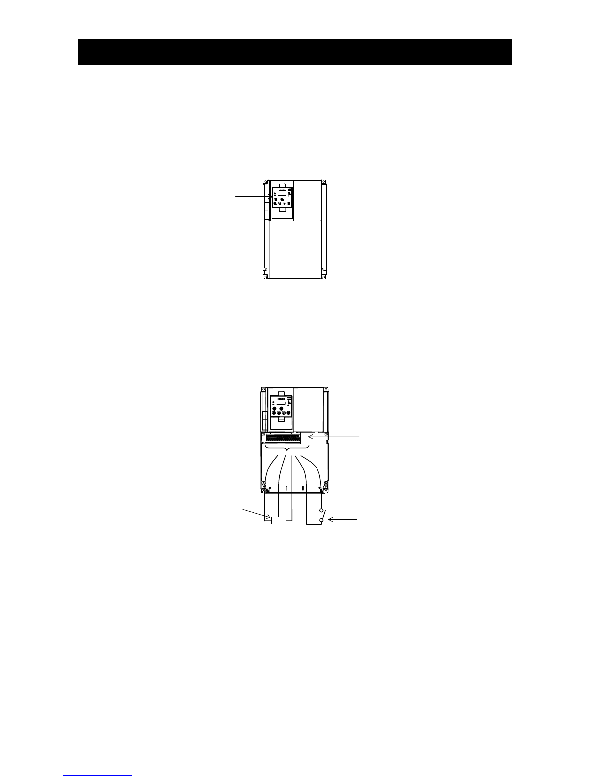
Chapter 3 Operation
3-2
You can operate the inverter in different ways, depending on how to input the operation and frequency-setting
commands as described below.
This section describes the features of operating methods and the items required for operation.
(1) Entering operation and frequency-setting commands from the digital operator
This operating method allows you to operate the inverter through key operations on the standard digital operator
mounted in the inverter or an optional digital operator.
When operating the inverter with a digital operator alone, you need not wire the control circuit terminals.
(Items required for operation)
*) Optional digital operator (not required when you use the standard digital operator)
(2) Entering operation and frequency-setting commands via control circuit terminals
This operating method allows you to operate the inverter via the input of operation signals from external devices
(e.g., frequency-setting circuit and start switch) to control circuit terminals. The inverter starts operation when the
input power supply is turned on and then an operation command signal (FW or RV) is turned on. You can select the
frequency-setting method (setting by voltage specification or current specification) through the input to a control
circuit terminal according to your system. For details, see Item (2), "Explanation of control circuit terminals," in
Section 2.2.1. (Items required for operation)
1) Operation command input device: External switch or relay
2) Frequency-setting command input device: External device to input signals (0 to 10 VDC, -10 to +10 VDC, or 4 to 20
mA)
(3) Entering operation and frequency-setting commands; both from a digital operator and via control circuit terminals
This operating method allows you to arbitrarily select the digital operator or control circuit terminals as the means
to input operation commands and frequency-setting commands. (Items required for operation)
1) See the items required for the above two operating methods.
(4) Operation by Easy sequence function (Drive programming function)
The inverter can be operated by downloading the user's program made with the dedicated PC software,
ProDriveNext. Please refer to “Easy sequence function” for details.
(5) Operation via communication
The inverter can be operated by an external communication device via Modbus-RTU or ASCII protocol (Hitachi
protocol) through the TM2 terminal on the control terminal l board. Please refer to “Communication function” for
details.
Digital operator
Operation command input device
(switch)
Frequency-setting command input
device (control)
Control circuit
terminal block
H O L
FW
CM1

Chapter 3 Operation
3-3
3.2 How To Operate the Digital Operator (OPE-SBK)
3.2.1 Names and functions of components
Name
Function
POWER lamp
Lights when the control circuit power is on.
ALARM lamp
Lights to indicate that the inverter has tripped.
RUN (operation) lamp
Lights to indicate that the inverter is operating.
PRG (program) lamp
Lights when the monitor shows a value set for a function.
This lamp starts blinking to indicate a warning (when the set value is invalid).
Monitor
Displays a frequency, output current, or set value.
Monitor lamps
Indicates the type of value and units displayed on the monitor. "Hz" (frequency), "V"
(voltage), "A" (current), "kW" (electric power), and "%" (percentage)
RUN key enable LED
Lights up when the inverter is ready to respond to the RUN key. (When this lamp is on,
you can start the inverter with the RUN key on the digital operator.)
RUN key
Starts the inverter to run the motor. This key is effective only when the RUN command
source setting A002 is set to “02”: digital operator. (To use this key, confirm that RUN
key enable LED is on.)
STOP/RESET key
Decelerates and stops the motor or resets the inverter from alarm status.
FUNC (function) key
Makes the inverter enter the monitor, function, or extended function mode.
STR (storage) key
Stores each set value. (Always press this key after changing a set value.)
1 (up) or 2 (down) key
Switches the inverter operation mode (among monitor, function, and extended
function modes) or increases or decreases the value set on the monitor for a function.
Monitor lamps
2 (down) key
ALARM lamp
POWER lamp
STR (storage) key
PRG (program) lamp
RUN key enable LED
1 (up) key
RUN (operation) lamp
Monitor
(4-digit LED display)
RUN key
FUNC (function) key
STOP/RESET key

Chapter 3 Operation
3-4
3.2.2 Code display system and key operations
This section describes typical examples of digital operator operation (in basic and full display modes) and an example
of special digital operator operation in extended function mode U.
The initial display on the monitor screen after power-on depends on the setting of function "b038". For details,
see Section 4.2.85, "Initial-screen selection," (on page 4-78).
When the setting of function "b038" is "01" (factory setting), the monitor initially shows as the
setting of function "d001" (output frequency monitoring). Pressing the key in this status changes the
display to .
Note: The display contents on the monitor depend on the settings of functions "b037" (function code display
restriction), "b038" (initial-screen selection), and "b039" (automatic setting of user parameters).
For details, see Sections 4.2.84, "Function code display restriction," (on page 4-76), 4.2.85 and "Initial-screen
selection," (on page 4-78).
Function name
Code
Default
Function code
display restriction
b037
00
Full display
Initial-screen
selection
b038
01
d001(Output frequency monitoring)
Automatic
user-parameter
setting function
enable
b039
00
Disabling
note: The following procedure enables you to turn the monitor display back to (*), displaying
, regardless of the current display mode:
- Hold down the key for 3 seconds or more. The monitor shows (*) alternately.
* The monitor shows only when the motor driven by the inverter is stopped. While the motor is
running, the monitor shows an output frequency. The displayed monitor depends on "b038" (initial-screen
selection).
FUNC
FUNC

Chapter 3 Operation
3-5
(1) Example of operation in full display mode ("b037" = "00" [factory setting])
All parameters can be displayed in full display mode. The display sequence of parameters matches their sequence
shown in Chapter 8, "List of Data Settings."
Key operation and
transition of codes on
display (in monitor or
function mode)
Key operation and
transition of monitored
data on display (in monitor
or function mode)
Key operation and
transition of codes on
display (in extended
function mode)
Key operation and
transition of monitored
data on display (in
extended function mode)
1
2
1
2
Pressing the or key respectively scrolls up or down the code displayed in code display mode or
increases or decreases the numerical data displayed in data display mode.
Press the or key until the desired code or numerical data is shown. To scroll codes or increase/decrease
numerical data fast, press and hold the key.
FUNC
Monitor
mode
(Monitor
display)
(*1)
(Data display)
(*1) (*2)
Function
mode
or
FUNC
STR
FUNC
FUNC
FUNC
FUNC
FUNC
or
FUNC
STR
or
FUNC
STR
or
FUNC
STR
or
FUNC
STR
or
FUNC
STR
or
FUNC
STR
or
FUNC
STR
FUNC
Extended
function
mode A
For the display and key
operation in extended
function mode U, see the
next page.
(*1) (*2)
(Data display)
Extended
function
mode B
Extended
function
mode C
Extended
function
mode H
Extended
function
mode P
or
FUNC
STR
FUNC
FUNC
STR
*1 The content of the display varies depending on
the parameter type.
*2 To update numerical data, be sure to press the
key after changing the data.

Chapter 3 Operation
3-6
(2) Code/data display and key operation in extended function mode U
The extended function mode U differs in operation from other extended function modes because the extended
function mode U is used to register (or automatically record) other extended-function codes as user-specified U
parameters.
Extended
function
mode U
Pressing the key
stores the value set here in
the corresponding U
parameter.
You cannot restore the
display with the
key.
or
FUNC
STR
STR
STR
Key operation and
transition of codes on
display (in monitor or
function mode)
Key operation and
transition of codes on
display (in extended
function mode U)
Key operation and transition
of codes on display (when
displaying extended-function
mode parameters from the
extended function mode U)
1
2
1
2
2
1
2
1
2
1
2
1
1
2
1
2
1
2
1
2
1
2
1
2
2
1
2
1
2
1
2
1
2
1
2
1
2
1
2
1
2
1
(Display with the factory
setting)
FUNC
FUNC
FUNC
Extended
function
mode A
Extended
function
mode B
Extended
function
mode C
Extended
function
mode H
Extended
function
mode P
Monitor
mode
Function
mode

Chapter 3 Operation
3-7
(3) Example of operation in basic display mode ("b037" = "04" )
- Only basic parameters can be displayed in basic display mode. (All parameters in monitor mode, four
parameters in function mode, or 24 parameters in extended function mode)
- Other parameters are not displayed. To display all parameters, select the full display mode ("b037" = "00").
<Displayable parameters and sequence of display>
Note:
If a desired parameter is not displayed, check the
setting of function "b037" (function code display
restriction). To display all parameters, specify "00"
for "b037".
No.
Display code
Item
1
d001 to d104
Monitor display
2
F001
Output frequency setting
3
F002
Acceleration (1) time setting
4
F003
Deceleration (1) time setting
5
F004
Operation direction setting
6
A001
Frequency source setting
7
A002
Run command source setting
8
A003
Base frequency setting
9
A004
Maximum frequency setting
10
A005
[AT] selection
11
A020
Multispeed frequency setting
12
A021
Multispeed 1 setting
13
A022
Multispeed 2 setting
14
A023
Multispeed 3 setting
15
A044
1st control method
16
A045
V/f gain setting
17
A085
Operation mode selection
18
b001
Selection of restart mode
19
b002
Allowable under-voltage power failure time
20
b008
Retry-after-trip selection
21
b011
Retry wait time after trip
22
b037
Function code display restriction
23
b083
Carrier frequency setting
24
b084
Initialization mode selection
25
b130
Selection of overvoltage suppression function
26
b131
Setting of overvoltage suppression level
27
C021
Setting of intelligent output terminal 11
28
C022
Setting of intelligent output terminal 12
29
C036
Alarm relay active state

Chapter 3 Operation
3-8
Key operation and transition of the
codes on display
Key operation and transition of the monitored data on display
Monitor mode
Pressing the key with a function code displayed shows the monitored data
corresponding to the function code.
(Monitor display) (*1)
Pressing the or key with the monitored data displayed reverts to the
display of the function code corresponding to the monitored data.
* With the factory setting, the monitor shows initially after
power-on.
Pressing the key in this status changes the display to .
Function or extended function mode
Pressing the key with a function code displayed shows the data
corresponding to the function code.
(Data display)
(*1)(*2)
Data setting
Pressing the or key respectively increases or
decreases the displayed numerical data.
(Press the key until the desired data is shown.)
Pressing the key with numerical data displayed stores the
data and then returns to the display of the corresponding
function code.
Note that pressing the key with numerical data displayed
returns to the display of the function code corresponding to
the numerical data without updating the data, even if it has
been changed on display.
or
Up to the
maximum limit
Down to the
minimum limit
1
2
or
FUNC
FUNC
FUNC
STR
FUNC
STR
FUNC
FUNC
STR
FUNC
FUNC
STR
FUNC
1 2 1
2
Pressing the or key respectively scrolls up or down the code displayed in code display mode or
increases or decreases the numerical data displayed in data display mode.
Press the or key until the desired code or numerical data is shown. To scroll codes or increase/decrease
numerical data fast, press and hold the key.

Chapter 3 Operation
3-9
(4) Procedure for directly specifying or selecting a code
- You can specify or select a code or data by entering each digit of the code or data instead of scrolling codes or
data in the monitor, function, or extended function mode.
- The following shows an example of the procedure for changing the monitor mode code "d001" displayed to
extended function code "A029":
("A029" is displayed.)
FUNC
STR
RUN
STOP/
RESET
FUNC
STR
RUN
STOP/
RESET
FUNC
RUN
STOP/
RESET
FUNC
STR
RUN
STOP/
RESET
STR
FUNC
RUN
STOP/
RESET
STR
FUNC
STR
RUN
STOP/
RESET
FUNC
RUN
STOP/
RESET
STR
FUNC
STR
RUN
STOP/
RESET
FUNC
STR
RUN
STOP/
RESET
FUNC
STR
FUNC
FUNC
STR
FUNC
(*2)
(*3)
2) Change to the extended function mode.
Press the and keys
together. (*1)
1
- Character "d" in the leftmost digit (fourth digit
from the right) starts blinking.
2
Press the key twice.
1
("A001" is displayed.)
(*3)
- Character "A" is blinking.
- Pressing the [STR] key determines the blinking
character.
(*2)
Press the key
(to determine character "A").
3) Change the third digit of the code.
- Character "0" in the third digit is blinking.
- Since the third digit need not be changed, press the
[STR] key to determine the character "0".
- Character "0" in the second digit is
blinking.
Press the
key.
(Character "0" is
determined.)
(*2)
4) Change the second digit of the code.
Press the key twice.
1
- Character "2" in the second digit is
blinking.
(*2)
(*2)
- Character "1" in the first digit is blinking.
STR
Press the key.
("A021" is displayed.)
5) Change the first digit of the code.
- Character "9" in the first digit is blinking.
Press the key eight times
or the key twice.
1
2
(*2)
STR
Press the
key.
(Character "9" is
determined.)
- Selection of code "A029" is completed.
* If a code that is not defined in the code list or
not intended for display is entered, the
leftmost digit (fourth digit) (character "A" in
this example) will start blinking again.
In such a case, confirm the code to be
entered and enter it correctly. For further
information, refer to Section 4.2.80. "
Function code display restriction," (on page
4-74), Section 4.2.81, "Initial-screen
selection," (on page 4-76), Section 4.2.82,
"Automatic user-parameter setting," (on
page 4-77), and Chapter 8, "List of Data
Settings."
7) Press the key to display the data
corresponding to the function code, change
the data with the and/or
key, and then press the key to
store the changed data. (*4)
Note that you can also use the procedure
(steps 1) to 6)) described here to change the
data. (*3)(*4)
*1
This procedure can also be used on screens
displaying a code other than "d001".
*2
If the key is pressed while a digit is
blinking, the display will revert to the
preceding status for entering the digit to the
right of the blinking digit.
*3
If the key is pressed while the leftmost
(fourth) digit is blinking, the characters
having been entered to change the code will
be cancelled and the display will revert to the
original code shown before the and
keys were pressed in step 1).
*4
When changing data, be sure to press the
key first.
FUNC
1
2
FUNC
FUNC
FUNC
1
2
STR
("d001" is displayed.)
1) Display the monitor mode code.
6) End the change of the extended function code.

Chapter 3 Operation
3-10
3.3 How To Make a Test Run
This section describes how to make a test run of the inverter that is wired and connected to external devices in a
general way as shown below.
For the detailed method of using the digital operator, see Section 3.2, "How To Operate the Digital Operator."
(1) When entering operation and frequency-setting commands from the digital operator:
(The operating procedure below is common to the standard and optional digital operators.)
(Operating procedure)
1) Confirm that all wirings are correct.
2) Turn on the earth-leakage breaker (ELB) to supply power to the inverter.
(The POWER lamp [red LED] of the digital operator goes on.)
* When using an inverter with the factory setting, proceed to step 5).
3) Select the digital operator as the operating device via the frequency source setting function.
- Display the function code "A001" on the monitor screen, and then press the key once.
(The monitor shows a 2-digit numeric value.)
- Use the and/or key to change the displayed numeric value to [02], and then press the
key once to specify the digital operator as the operating device to input frequency-setting commands.
(The display reverts to [A001].)
4) Select the digital operator as the operating device by the run command source setting function.
- Display the function code "A002" on the monitor screen, and then press the key once.
(The monitor shows a 2-digit numeric value.)
- Use the and/or key to change the displayed numeric value to "02", and then press the
key once to specify the digital operator as the operating device to input operation commands.
(The display reverts to [A002]. The operating device indicator lamp above the [RUN] key goes on.)
5) Set the output frequency.
- Display the function code "F001" on the monitor screen, and then press the key once.
(The monitor shows a preset output frequency. With the factory setting, [0 Hz] is shown.)
- Use the and/or key to change the displayed numeric value to the desired output frequency, and then
press the key once to determine the frequency.
(The display reverts to [F001].)
6) Set the operation direction of the motor.
- Display the function code "F004" on the monitor screen, and then press the key once.
(The monitor shows "00" or "01".)
G
Type-D grounding (200 V class model)
Type-C grounding (400 V class model)
DC reactor
Motor
U V W
PD
P
RB N AL0
AL1
AL2
11
CM2
15
SP
SN
RP
SN
Braking unit
Alarm output contacts
AMI
AM L O2
OI O H
P24
PLC
CM1
TH
FM
1 8 FW R S
T
R
S
T
3-phase power
supply
ELB
.
.
.
Digital operator
.
.
.
FUNC
FUNC
STR
STR
1
2
FUNC
1
2
STR
1
2
FUNC
Default jumper position for sinking type inputs
(Altanatively, CM1-PLC for souricing tiype)

Chapter 3 Operation
3-11
- Use the and/or key to change the displayed value to "00" for forward operation or "01" for reverse
operation, and then press the key once to determine the operation direction.
(The display reverts to [F004].)
7) Set the monitor mode.
- To monitor the output frequency, display the function code "d001", and then press the key once.
(The monitor shows the output frequency.)
To monitor the operation direction, display the function code "d003", and then press the key once.
(The monitor shows for forward operation, for reverse operation, or for stopping.)
8) Press the key to start the motor.
(The RUN lamp [green LED] goes on.)
9) Press the key to decelerate or stop the motor.
(When the motor stops, the RUN lamp [green LED] goes off.)
- During the test run, confirm that the inverter does not trip while accelerating or decelerating the motor and that
the motor speed and frequencies are correct.
- If a trip due to overcurrent or overvoltage has occurred during the test run, increase the acceleration and
deceleration time.
- Make sure that there is enough margin to trip level by monitoring the output current (d002) and DC voltage
(d102).
STR
1
2
FUNC
FUNC
RUN
STOP/
RESET

Chapter 3 Operation
3-12
(Operating procedure)
1) Confirm that all wirings are correct.
2) Turn on the earth-leakage breaker (ELB) to supply power to the inverter.
(The POWER lamp [red LED] of the digital operator goes on.)
3) Select the control circuit terminal block as the device to input frequency-setting commands by the frequency
source setting function.
- Display the function code "A001" on the monitor screen, and then press the key once.
(The monitor shows a 2-digit numeric value.)
- Use the and/or key to change the displayed numeric value to [01], and then press the
key once to specify the control circuit terminal block as the device to input frequency-setting commands.
(The display reverts to [A001].)
4) Select the control circuit terminal block as the device to input operation commands by the run command source
setting function.
- Display the function code "A002" on the monitor screen, and then press the key once.
(The monitor shows a 2-digit numeric value.)
- Use the and/or key to change the displayed numeric value to "01", and then press the
key once to specify the digital operator as the device to input operation commands.
(The display reverts to [A002].)
5) Set the monitor mode.
- To monitor the output frequency, display the function code "d001", and then press the key once.
(The monitor shows the output frequency.)
To monitor the operation direction, display the function code "d003", and then press the key once.
(The monitor shows for forward operation, for reverse operation, or for stopping.)
6) Start the motor operation.
- Set the FW signal (at the FW terminal on the control terminal block) to the ON level to start the motor.
(The RUN lamp [green LED] goes on.)
- Apply a voltage across the terminals O and L on the control circuit block to output the frequency corresponding
to the applied voltage from the inverter.
7) Stop the motor.
- Set the FW signal (at the FW terminal on the control terminal block) to the OFF level to decelerate and stop the
motor.
(When the motor stops, the RUN lamp [green LED] goes off.)
U V W
PD P RB N AL0
AL1
AL2
11
・・・・
CM2
15
SP
SN
RP
SN
G
H
L O H
Operating box
(OPE-4MJ2)
(OPE-8MJ2)
AMI
AM
L
O2
OI
O
P24
PLC
CM1
TH
FM
1
8
FW
R S T
R
S
T
ELB
(RV)
Type-D grounding (200 V class model)
Type-C grounding (400 V class model)
DC reactor
Motor
Braking unit
3-phase power
supply
Digital operator
FUNC
1
2
FUNC
1
2
STR
STR
FUNC
FUNC
Default: for sinking type
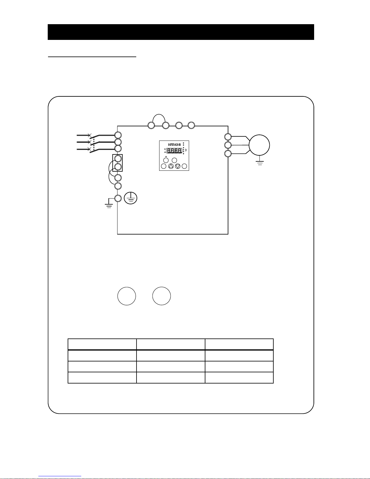
Chapter 3 Operation
3-13
3.4 Example of I/O connections
Example 1: Frequency command source Setting data in F001 (Digital Operator)
Run command source RUN/STOP key (Digital Operator)
*) SJ700D-****FF3 (Initial settings)
(1) I/O connections
(2) Operation
Frequency: By using the digital operator, set the frequency command into parameter F001.
Run/Stop: Push the key and on the digital operator to run and stop.
*) Refer to 3.5.2 for changing the frequency command source and 3.5.3 for changing the run
command source.
(3) Parameter settings
Parameter Details Setting data
A001 Digital Operator
A002 Digital Operator
F001 Output frequency setting
.
Note)
Note) Initial settings are 0.00Hz. You need to set the appropriate data.
ELB
R/L1
S/L2
T/L3 R T
R0
T0
P
PD N RB
U V W M 3-phase induction motor
RUN
STO P/
RESET

Chapter 3 Operation
3-14
Example 2: : Frequency command source External potentiometer (Control terminal)
Run command source RUN/STOP key (Control panel)
(1) I/O connections
(2) Operation
Frequency: Set the frequency command via a potentiometer connected to H/O/L terminal.
Run/Stop: Push the key and to run and stop.
*) Refer to 3.5.2 for changing the frequency command source and 3.5.3 for changing the run
command source.
(3) Parameter settings
Parameter Details Setting data
A001 Control circuit terminal block
A002 Digital Operator
H O L
Potentiometer
R/L1
S/L2
T/L3
R T R0
T0
P
PD N RB
ELB
U V W
M
3-phase induction motor
RUN
STO P/
RESET

Chapter 3 Operation
3-15
Example 3: Frequency command source Setting data in F001 (Control panel) + multi speed select
Run command source External signal (Control terminal)
(1) I/O connections
*) In case of SJ700D-****FUF3, you need to set C006=03 and C016=00.
*) You need to set multi speed frequency command into parameters (from A020 to A022).
*) Refer to 3.5.2 for changing the frequency command source and 3.5.3 for changing the run
command source.
(2) Operation
Frequency: By using the multi speed terminals, set the frequency command.
Run/Stop: Using the forward / reverse terminal to run and stop.
(3) Parameter settings
Parameter Details Setting data
A001 Digital Operator
A002 Control circuit terminal block
A020 Multi speed 1 and 2 are not active.
. Note)
A021
Multi speed 1is active and
multi speed 2 is not active.
. Note)
A022
Multi speed 1is not active and
multi speed 2 is active.
. Note)
Note) Initial settings are 0.00Hz. You need to set the appropriate data.
FW
8:RV
CM1
Forward
7:CF1
6:CF2
P24
PLC
Reverse
Multi-speed1
Multi-speed2
CM1
P24
PLC
Sink logic
Source logic
R/L1
S/L2
T/L3
R T R0
T0 P PD N RB
ELB
U V W
M
3-phase induction motor
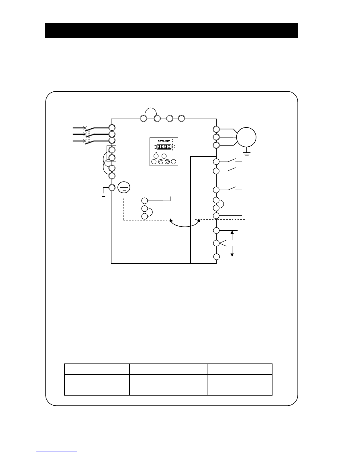
Chapter 3 Operation
3-16
Example 4: Frequency command source External analog voltage source and current source (Control terminal)
Run command source External signal (Control terminal)
*) SJ700D-****FEF3/FUF3 (Initial settings)
(1) I/O connections
*) Refer to 3.5.2 for changing the frequency command source and 3.5.3 for changing the run
command source.
(2) Operation
Frequency: Using the voltage source and current source to set the frequency command with analog
select terminal (AT terminal: OFF: Voltage command / ON: Current command).
* AT terminal is used to switch the analog input O and OI to which the inverter refers as the
frequency command. (e.g. When AT terminal is OFF, the inverter outputs the frequency
according to the voltage input given to the O terminal)
Run/Stop: Using the forward / reverse terminal to run and stop.
(3) Parameter settings
Parameter Details Setting data
A001 Control circuit terminal block
A002 Control circuit terminal block
FW
8:RV
CM1
Forward
2:AT
P24
PLC
Reverse
Analog select
CM1
P24
PLC
Sink logic
Source logic
R/L1
S/L2
T/L3 R T
R0
T0
P
PD N RB
OI
O
L
Voltage source
(0V to 10V)
Current source
(4mA to 20mA)
ELB
U
V
W
(+)
(-)
(+)
(-)
M
3-phase induction motor

Chapter 3 Operation
3-17
3.5 Basic Parameter Setting to Drive Motor
3.5.1 Setting Frequency command source and Run command source
This section describes how to drive the motor with SJ700D briefly.
The frequency and run command are necessary to drive the motor with the inverter.
In many cases, these sources are set as below;
Setting the frequency : (A) Data settings (Digital operator)
(B) Via external analog signals (Control terminal)
Run and stop : (A) RUN / STOP key (Digital operator)
(B) Via external signal (Control terminal)
The frequency command and Run command sources can be changed by the parameter A001 (Frequency command
source) and A002 (Run command source) respectively.
In addition to the basic setting mentioned above, there are several options for A001 and A002 setting.
Parameter
Detail
Data range
Initial settings
****FF3
****FEF3
****FUF3
A001
Frequency source
00(keypad potentiometer)
01(control circuit terminal block)
02(operator)
03(RS485)
04(option 1)
05(option 2)
06(pulse-string input)
07(easy sequence)
10(operation function result)
02
01
A002
Run command source
01(control circuit terminal block)
02(operator)
03(RS485)
04(option 1)
05(option 2)
02
01
*) This chapter explains 01(control circuit terminal block) and 02(operator) mainly.

Chapter 3 Operation
3-18
3.5.2 Frequency command source selection
Key operation to set A001
****FF3 : Change A001 from 02 (operator) to 01 (control circuit terminal block).
Procedure Key operation Indication Details
1-1
.
After powering up of the inverter, the operator displays 0.00,
output frequency monitor (d001)
1-2
Indication changes from data display (0.00) to parameter
display (d001).
1-3
or
Push the key and select the head of Group A.
1-4
Push the key and indication changes from A--- to A001.
1-5
Push the key and indication changes to 02(operator).
1-6
Push the key and change from 02 to 01 (control circuit
terminal block).
1-7
Push the key and indication changes A001 (Data save).
1-8
.
By pushing the key for more than three seconds,
indication changes to the output frequency data (d001).
****FEF3/FUF3 : Change from 01 (control circuit terminal block) to 02 (operator).
*) Replace the procedure 1-5 and 1-6 in the list above with 1-5’ and 1-6’ in the list below.
Procedure Key operation Indication Details
1-5’
Push the key and indication changes to 01(control circuit
terminal block).
1-6’
Push the key and change the data to 02 (operator).
FUNC
FUNC
STR
FUNC
FUNC
1
2
2
1
FUNC

Chapter 3 Operation
3-19
Setting frequency command
(A) A001=02: Digital operator
With this setting, the value set in the parameter F001 defines the target frequency of the inverter.
The procedure below shows an example of a procedure to set F001=40Hz.
Procedure Key operation Indication Details
2-1
.
After powering up of the inverter, the operator displays
0.00, output frequency monitor (d001)
2-2
Indication changes from data (0.00) to parameter (d001).
2-3
or
Push the key and select F001 (setting frequency).
2-4
.
Push the key and indication changes setting frequency.
2-5
or
.
(Example) Set the frequency to 40Hz.
2-6
Push the key and indication goes back to F001 (Data save).
note)
2-7
.
By pushing the key for more than three seconds,
the indication changes to the output frequency data.
note) In case of the setting A001=02, on displaying the output frequency, the setting frequency can change by the up
and down keys.
(B) A001=01: Control terminal
The frequency command can be changed in accordance with the analog input given to the O/OI terminal on the
control terminal by using a potentiometer (connected to H/O/L terminal) or an analog voltage / current supply. With
this setting, the parameter F001 indicates the frequency command value given via the control terminal. Please refer
to
4.2.11 External analog inputsetting (O, OI, and O2) or 4.2.14 Start/end frequency setting for external analog input.
(C) Multi-speed selection – Binary operation
The inverter can store several target frequencies (up to 16), which is useful to define such low / middle / high
frequencies and those frequencies are switched by external signals. The actual target frequency is selected from
those pre-set frequencies in accordance with the signal status of the multi speed inputs. This part describes an
example using 3 frequency sets.
Parameters Condition Setting
A001 Operator
*1)
A020 Multi speed 1 and 2 are not active.
.*2)
A021
Multi speed 1is active and
multi speed 2 is not active.
.*2)
A022
Multi speed 1is not active and
multi speed 2 is active.
.*2)
*1) In case multi speed 1 and 2 are not active, the setting of A001 defines the frequency command source.
In case of A001=02, and if multi speed 1 and 2 are not active, F001 adopts the A020 value.
*2) Initial settings are 0.00Hz. You should set the appropriate data.
1
2
1
2
STR
FUNC
FUNC
FUNC

Chapter 3 Operation
3-20
3.5.3 Run command source selection
Key operation to set A002
****FF3 : Change from 02 (operator) to 01 (control circuit terminal block).
Procedure Key operation Indication Details
3-1
.
After powering up of the inverter, the operator displays
0.00, output frequency monitor (d001)
3-2
Indication changes from data (0.00) to parameter (d001).
3-3
or
Push the key and select the head of Group A.
3-4
Push the key and indication changes to A001.
3-5
Push the key and select A002 (Run command source).
3-6
Push the key and indication changes to 02(operator).
3-7
Push the key and change the data to 01 (control circuit
terminal block).
3-8
Push the key and indication changes to A002 (Data save).
3-9
.
By pushing the key for more than three seconds,
indication changes to the output frequency data.
****FEF3/FUF3 : Change 01 (control circuit terminal block) to 02 (operator).
*) Replace the procedure 3-6 and 3-7 on the list above with 3-6’ and 3-7’ in the list below.
Procedure Key operation Indication Details
3-6’
Push the key and indication changes to 01 (control circuit
terminal block).
3-7’
Push the key and change to 02(operator).
FUNC
STR
1
2
FUNC
FUNC
FUNC
FUNC
1
2
1

Chapter 3 Operation
3-21
Operating run command
(A) A001=02: Digital operator
RUN and STOP key on the digital operator allows you to start and stop the motor respectively.
RUN: STOP:
*) Changing the rotatory direction can be done by changing the parameter F004, keypad run key routing or to exchange
any two phases of the wiring to the motor. Before wiring, you should confirm that the power supply to the inverter
has been cut off.
(B) A001=01: Control terminal
You can start and stop the motor operation via the FW terminal (forward rotation) or RV terminal (Reverse rotation).
In case of terminal FW:
Sink logic (short between P24 and PLC)
FW-CM1 short: The inverter runs the motor in the forward direction --- RUN command is active.
FW-CM1 open: The inverter decelerates and stops the motor --- RUN command is not active.
Source logic (short between CM1 and PLC)
FW-P24 short: The inverter runs the motor in the forward direction --- RUN command is active.
FW-P24 open: The inverter decelerates and stops the motor --- RUN command is not active.
RUN
STOP/
RESET
ON
Motor
Speed
Time
RUN
command
Frequency
command
Motor
speed

Chapter 3 Operation
3-22
3.6 Dual rating selection
The SJ700D-3 series inverter has Dual Rating, so that it can work in two different types
of load condition, Constant torque application and Variable torque application. Select
parameter b049 depending on your application.
Name
Function code
Data
Description
Dual rating selection
b049
00
CT : Constant Torque
01
VT : Variable Torque
- The rating of Constant Torque mode (CT) is same as SJ700-2 series.
Overload current characteristic is 150% current / 60 seconds.
- You can use Variable Torque mode (VT), in case the motor works with over rating torque infrequently.
When you select VT mode, rated current specification is changed up into VT mode larger than CT mode,
you can choose the one size bigger capasity motor than the inverter capacity.
Note, overload current characteristic is 120% current / 60 seconds.
- You can set CT mode or VT mode to change b049 without power cutting off.
Heavy load (CT)
Normal load (VT)
Usage
For heavy load with high torque required
at start, acceleration and deceleration.
For nomal road without high torque
required.
Applications
Elevators, cranes, conveyers, etc.
Fans, pumps, air-conditionings,etc
Rated current
(example)
46.0A (3-phase 200V 11.0kW)
58.0A (3-phase 200V 11.0kW)
Overload current
150% 60 sec
120% 60 sec
- When you change to CT mode or VT mode at b049, setting range and an initial value of some parameters change,
and someparameters are initialized. You need to set some Initialized parameters with setting b049.
b049: Dual rating selection
Related code

Chapter 3 Operation
3-23
- Note that there are diffrence of setting range and defaults between CT mode and VT mode.
- Note that when VT mode (b049=01) is selected, some data are overwritten by VT mode default (refer to below).
Name
Function
code
Constant torque mode (CT)
Variable torque mode (VT)
Range
default
Range
default
V/F characteristic curve
selection, 1st motor
A044
00 (VC), 01 (VP), 02 (free V/f),
03 (sensorless vector control),
04 (0Hz sensorless vector control),
05(vector with sensor)
00 (VC)
00 (VC), 01 (VP), 02 (free V/f),
03 (sensorless vector control),
00 (VC)
V/F characteristic curve
selection, 2nd motor
A244
00 (VC), 01 (VP), 02 (free V/f),
03 (sensorless vector control),
04 (0Hz sensorless vector control),
05(vector with sensor)
00 (VC)
00 (VC), 01 (VP), 02 (free V/f),
03 (sensorless vector control),
00 (VC)
DC braking force during
deceleration
A054
0. to 100.(%)
<0. to 80.(%)>
0(%)
0. to 70.(%)
< 0. to 50.(%) >
0(%)
DC braking force for
starting
A057
0. to 100.(%)
<0. to 80.(%)>
0(%)
0. to 70.(%)
<0. to 50.(%)>
0(%)
DC braking carrier
frequency setting
A059
0.5 to 15.0(kHz)
<0.5 to 10.0(kHz)>
5.0(kHz)
<3.0(kHz)>
0.5 to 12.0(kHz)
<0.5 to 8.0(kHz)>
3.0(kHz)
Operation mode
selection
A085
00 (normal operation),
01 (energy-saving operation)
02 (fuzzy operation)
00 (normal
operation)
00 (normal operation),
01 (energy-saving operation)
00 (normal
operation)
Overload restriction
setting
b022
0.20 to 2.00 x Rated current(A)
<0.20 to 1.80 x Rated current(A)>
1.50 x Rated
current (A)
0.20 to 1.50 x Rated current(A)
1.20 x Rated
current(A)
Overload restriction
setting (2)
b025
Active frequency
matching, scan start
frequency
b028
0.20 to 2.00 x Rated current(A)
<0.20 to 1.80 x Rated current(A)>
Rated
current (A)
0.20 to 1.50 x Rated current(A)
Rated
current(A)
Torque limit (1)
(forward-driving in
4-quadrant mode)
b041
0. to 200.(%)/ __no
<0. to 180.(%)/ __no>
150(%)
0. to 150.(%)/ __no
120(%)
Torque limit (2)
(reverse-regenerating
in 4-quadrant mode)
b042
Torque limit (3)
(reverse-driving in
4-quadrant mode)
b043
Torque limit (4)
(forward-regenerating
in 4-quadrant mode)
b044
Note: < > indicate the setting range of 75 to 150kW
Note: When CT mode (b049=00) is selected, A044/A244 are renewed to 00(VC).

Chapter 3 Operation
3-24
Name
Function
code
Heavy load (CT)
Normal load (VT)
Range
default
Range
default
Carrier frequency
setting
b083
0.5 to 15.0(kHz)
<0.5 to 10.0(kHz)>
5.0(kHz)
<3.0(kHz)>
0.5 to 12.0(kHz)
<0.5 to 8.0(kHz)>
3.0(kHz)
Brake control enable
b120
00 (disabling), 01 (enabling)
00
(disabling)
(Unavailable)
(Unavailable)
Digital current monitor
reference value
C030
0.20 x Rated current to 1.50 x
Rated current (A)
(Current with digital current
monitor output at 1,440 Hz)
Rated
current (A)
0.20 x Rated current to 1.50 x
Rated current (A)
(Current with digital current
monitor output at 1,440 Hz)
Rated
current (A)
Low-current indication
signal detection level
C039
0.00 to 2.00 x rated current(A)
<0.00 to 1.80 x Rated current(A)>
Rated
current (A)
0.00 to 1.50 x Rated current
(A)
Rated
current (A)
Overload level setting
C041
0.00 to 2.00 x rated current (A)
<0.00 to 1.80 x Rated current(A)>
Rated
current (A)
0.00 to 1.50 x Rated current
(A)
Rated
current (A)
Over-torque
(forward-driving) level
setting
C055
0. to 200.(%)
<0. to 180.(%)>
100(%)
0. to 150.(%)
100(%)
Over-torque (reverse
regenerating) level
setting
C056
Over-torque (reverse
driving) level setting
C057
Over-torque (forward
regenerating) level
setting
C058
Overload setting (2)
C111
0.00 to 2.00 x rated current
<0.00 to 1.80 x Rated current(A)>
Rated
current (A)
0.00 to 1.50 x Rated current
(A)
Rated
current (A)
Note: < > indicate the setting range of 75 to 150kW

Chapter 3 Operation
3-25
(Memo)

Chapter 4 Explanation of Functions
This chapter describes the functions of the inverter.
4.1 Monitor Mode ·························································· 4 - 1
4.2 Function Mode ························································· 4 - 7
4.3 Functions Available When the Feedback
Option Board (SJ-FB) Is Mounted ····························· 4 - 96
4.4 Communication Functions ······································· 4 - 113

Chapter 4 Explanation of Functions
4-1
4.1 Monitor Mode
4.1.1 Output frequency monitoring
When the output frequency monitoring function (d001) is selected, the inverter
displays the output frequency. The inverter displays "0.00" when the frequency
output is stopped.
The Hz monitor lamp lights up while the inverter is displaying the output frequency.
(Display)
0.00 to 99.99 in steps of 0.01 Hz
100.0 to 400.0 in steps of 0.1 Hz
Note: When you have selected the digital operator as the device to input frequency-setting commands (A001=02), you
can change the output frequency setting by using the and/or key (only while the inverter is operating the
motor).
- The change in output frequency made in this mode can be reflected in the frequency setting (function "F001").
Press the STR key to write the new frequency over the currently selected frequency setting.
- You cannot change the output frequency while the PID function is enabled or the inverter is not operating the
motor.
4.1.2 Output current monitoring
When the output current monitoring function (d002) is selected, the inverter
displays the output current. The inverter displays "0.0" when the current output is
stopped.
The A monitor lamp lights up while the inverter is displaying the output current.
(Display)
0.0 to 999.9 in steps of 0.1 A
4.1.3 Rotation direction monitoring
When the rotation direction monitoring function (d003) is selected, the inverter
displays the motor operation direction.
The RUN lamp lights up while the inverter is operating the motor (in forward or reverse direction).
(Display)
F: Forward operation
o: Motor stopped
r: Reverse operation
4.1.4 Process variable (PV), PID feedback monitoring
When "01" (enabling PID operation) or "02" (enabling inverted-data output) has
been specified for function "A071" (PID Function Enable) and the process
variable (PV), PID feedback monitoring function (d004) is selected, the inverter
displays the PID feedback data.
You can also convert the PID feedback to gain data by setting a PV scale conversion (with function "A075").
Value displayed by function "d004" = "feedback quantity" (%) x " PV scale conversion (A075)"
The PV scale conversion can be set (by function "A075") within the range 0.01 to 99.99 in steps of 0.01.
(Display)
0.00 to 99.99 in steps of 0.01
100.0 to 999.9 in steps of 0.1
1000. to 9999. in steps of 1
100 to 999 in units of 10
d001: Output frequency monitoring
Related code
d002: Output current monitoring
Related code
d003: Rotation direction monitoring
Related code
d004: Process variable (PV),
PID feedback monitoring
A071: PID Function Enable
A075: PV scale conversion
Related code

Chapter 4 Explanation of Functions
4-2
4.1.5 Intelligent input terminal status
When the intelligent input terminal status function (d005) is selected, the
inverter displays the states of the inputs to the intelligent input terminals.
The internal CPU of the inverter checks each intelligent input for significance, and the inverter displays active inputs
as those in the ON state. (*1)
Intelligent input terminal status is independent of the a/b contact selection for the intelligent input terminals.
(Example)
FW terminal and intelligent input terminals [7], [2], and [1]: ON
Intelligent input terminals [8], [6], [5], [4], and [3]: OFF
(*1)When input terminal response time is set, terminal recognition is delayed. (refer 4.2.79)
4.1.6 Intelligent output terminal status
When the intelligent output terminal status function (d006) is selected, the
inverter displays the states of the outputs from the intelligent output terminals.
This function does not monitor the states of the control circuit terminals but monitors those of the outputs from the
internal CPU.
Intelligent input terminal status is independent of the a/b contact selection for the intelligent input terminals.
(Example)
Intelligent output terminals [12] and [11]: ON
Alarm relay terminal AL and intelligent output terminals [15] to [13]: OFF
4.1.7 Scaled output frequency monitoring
When the scaled output frequency monitoring (d007) is selected, the inverter
displays the gain data converted from the output frequency with the
frequency scaling conversion factor (b086).
Use this function, for example, to change the unit of a value (e.g., motor speed) on display.
Value displayed by function "d007" = "output frequency monitor(d001)" x "frequency scaling conversion factor (b086)"
The frequency scaling conversion factor (b086) can be set within the range 0.1 to 99.9 in steps of 0.1.
(Example) Displaying the speed of a 4-pole motor
Speed N (min-1) = (120 x f [Hz])/pole = f (Hz) x 30
As the result of the above calculation with the factor (b086) set to 30.0, the inverter displays "1800" (60 x 30.0)
when the output frequency is 60 Hz.
(Display)
0.00 to 99.99 in steps of 0.01
100.0 to 999.9 in steps of 0.1
1000. to 9999. in steps of 1
1000 to 3996 in units of 10
Note: When you have selected the digital operator as the device to input frequency-setting commands, you can
change the output frequency setting by using the △ and/or ▽ key (only while the inverter is operating the
motor).
- The change in output frequency made in this mode can be reflected in the frequency setting (function "F001").
Press the STR key to write the new frequency over the currently selected frequency setting. (The precision of
the storable frequency data depends on the frequency setting.)
- You cannot change the output frequency while the PID function is enabled or the inverter is not operating the
motor.
ON
ON
OFF
FW
OFF
1
(ON) 2 (ON) 3 (OFF) 4 (OFF) 5 (OFF) 6 (OFF) 7 (ON) 8 (OFF)
Display
: The segment is on, indicating
the ON state.
: The segment is off, indicating
the OFF state.
Intelligent input terminals
ON
OFF
11
(ON)
12
(ON)
13
(OFF)
14
(OFF)
15
(OFF)
AL
(OFF)
Display
: The segment is on, indicating
the ON state.
: The segment is off, indicating
the OFF state.
Intelligent input terminals
d005: Intelligent input terminal status
Related code
d006: Intelligent output terminal status
Related code
d007: Scaled output frequency monitoring
b086: Frequency scaling conversion factor
Related code

Chapter 4 Explanation of Functions
4-3
4.1.8 Actual-frequency monitoring
The actual-frequency monitoring function is effective only when a motor
equipped with an encoder is connected to the inverter and the feedback option
board (SJ-FB) is mounted in the inverter. When the actual-frequency monitoring
function (d008) is selected, the inverter displays the actual operating frequency
of the motor (regardless of the motor control method (A044 or A244)).
(Display)
Forward operation: Reverse operation:
0.00 to 99.99 in steps of 0.01 Hz- 0.0 to -99.9 in steps of 0.1 Hz
100.0 to 400.0 in steps of 0.1 Hz -100 to -400 in steps of 1 Hz
Note: To use this monitoring function, set the encoder pulse-per-revolution (PPR) setting (P011) and the number of
motor poles (H004 or H204) correctly.
4.1.9 Torque command monitoring
The torque command monitoring function is effective when you have selected
control by torque for the vector control with sensor. When the torque
command monitoring function (d009) is selected, the inverter displays the
value of the currently input torque command.
The % monitor lamp lights up while the inverter is displaying the torque command value.
Assign 52 (ATR) on intelligent input terminal and turn on to activate torque control.
(Display)
0. to 200. in steps of 1 %
4.1.10 Torque bias monitoring
The torque bias monitoring function is effective when you have selected the
vector control with sensor. When the torque bias monitoring function (d010) is
selected, the inverter displays the value of the currently set value of torque bias.
The % monitor lamp lights up while the inverter is displaying the torque bias
value.
(Display)
-150. to +150. in steps of 1 %
4.1.11 Torque monitoring
When the torque monitoring function (d012) is selected, the inverter displays the
estimated value of the torque output from the inverter.
The % monitor lamp lights up while the inverter is displaying the estimated output torque.
(Display)
-300. to +300. in steps of 1 %
Note: This monitoring function is effective only when you have selected the sensorless vector control, 0Hz-range
sensorless vector control, or vector control with sensor as the control mode.
Displayed value is not accurate when the other control method is selected.
4.1.12 Output voltage monitoring
When the output voltage monitoring function (d013) is selected, the inverter
displays the voltage output from the inverter.
The V monitor lamp lights up while the inverter is displaying the output voltage.
(Display)
0.0 to 600.0 in steps of 0.1 V
(remark) Displayed value may not be accurate when the output voltage is differ from input voltage.
4.1.13 Power monitoring
When the power monitoring function (d014) is selected, the inverter displays the
electric power (momentary value) input to the inverter.
The kW monitor lamps (V and A lamps) light up while the inverter is displaying the input power.
(Display)
0.0 to 999.9 in steps of 0.1 kW
d009: Torque command monitoring
P033: Torque command input selection
P034: Torque command setting
A044: V/f characteristic curve selectcion
C001 to C008: Terminal [1] to [8] functions
Related code
d013: Output voltage monitoring
Related code
d014: Power monitoring
Related code
d010: Torque bias monitoring
A044: V/f characteristic curve selectcion
P036: Torque bias mode
P037: Torque bias value
P038: Torque bias polarity
Related code
Related code
d012: Torque monitoring
A044: V/f characteristic curve selectcion
d008: Actual-frequency monitoring
P011: Encoder pulse-per-revolution (PPR)
setting
H004: Motor poles setting, 1st motor
H204: Motor poles setting, 2nd motor
Related code

Chapter 4 Explanation of Functions
4-4
4.1.14 Cumulative power monitoring
When the cumulative power monitoring function is selected, the inverter
displays the cumulative value of electric power input to the inverter.
You can also convert the value to be displayed to gain data by setting the
cumulative input power display gain setting (b079).
Value displayed by function "d015" = "calculated value of input power (kW/h)"/"cumulative input power display gain
setting (b079)" The cumulative power input gain can be set within the range 1 to 1000 in steps of 1.
You can clear the cumulative power data by specifying "01" for the cumulative power clearance function (b078) and
pressing the STR key.
You can also clear the cumulative power data at an intelligent input terminal by assigning function "53" (KHC:
cumulative power clearance) to the intelligent input terminal.
When the cumulative input power display gain setting (b079) is set to "1000", the cumulative power data up to 999000
(kW/h) can be displayed.
(Display)
0.0 to 999.9 in steps of 1 kW/h, or the unit set for function "b079"
1000 to 9999 in units of 10 kW/h, or the unit set for function "b079"
100 to 999 in units of 1000 kW/h, or the unit set for function "b079"
4.1.15 Cumulative operation RUN time monitoring
When the cumulative operation RUN time monitoring function (d016) is elected,
the inverter displays the cumulative time of the inverter operation.
(Display)
0. to 9999. in units of 1 hour
1000 to 9999 in units of 10 hours
100 to 999 in units of 1,000 hours
4.1.16 Cumulative power-on time monitoring
When the cumulative power-on time monitoring function(d017) is selected,
the inverter displays the cumulative time throughout which the inverter power has been on.
(Display)
0. to 9999. in units of 1 hour
1000 to 9999 in units of 10 hours
100 to 999 in units of 1,000 hours
4.1.17 Heat sink temperature monitoring
When the heat sink temperature monitoring function (d018) is selected, the inverter
displays the temperature of the internal heat sink of the inverter.
(Display)
0.0 to 200.0 in steps of 0.1 °C
4.1.18 Motor temperature monitoring
When the motor temperature monitoring function is selected, the inverter
displays the temperature of the thermistor connected between control circuit
terminals TH and CM1.Use the thermistor model PB-41E made by Shibaura
Electronics Corporation. Specify "02" (enabling NTC) for the thermistor for
thermal protection control (function "b098").
(Display)
0.0 to 200.0 in steps of 0.1 °C.
Note: If "01" (enabling PTC) is specified for the thermistor for thermal protection control (function "b098"), motor
temperature monitoring is disabled.
4.1.19 Life-check monitoring
When the life-check monitoring function (d002) is selected, the inverter displays
the operating life status of two inverter parts output from corresponding
intelligent output terminals by using LED segments of the monitor.
The two targets of life-check monitoring are:
1: Life of the capacitor on the main circuit board
2: Degradation of cooling fan speed
d015: Cumulative power monitoring
b078: Cumulative power clearance
b079: Cumulative input power display gain
setting
Related code
d019: Motor temperature monitoring
b098: Thermistor for thermal
protection control
Related code
d022: Life-check monitoring
Related code
1
2
Life check
Normal
d016: Cumulative operation
RUN time monitoring
Related code
d017: Cumulative power-on
time monitoring
Related code
d018: Heat sink temperature
monitoring
Related code

Chapter 4 Explanation of Functions
4-5
Note 1: The inverter estimates the capacitor life every 10 minutes. If you turn the inverter power on and off
repeatedly at intervals of less than 10 minutes, the capacitor life cannot be checked correctly.
Note 2: If you have specified "01" for the selection of cooling fan operation (function "b0092"), the inverter
determines the cooling fan speed to be normal while the cooling fan is stopped.
4.1.20 Program counter display (easy sequence function)
While the easy sequence function is operating, the inverter displays the program
line number that is being executed.
For details, refer to the “Programming Software EzSQ” manual.
4.1.21 Program number monitoring (easy sequence function)
When the program number monitoring function (d024) is selected, the inverter
displays the program number of the downloaded easy sequence program.
Note that you must describe a program number in the program you create. For details, refer to the “Programming
Software EzSQ” manual.
4.1.22 User Monitors 0 to 2 (easy sequence function)
The user monitor function allows you to monitor the results of operations in an easy sequence program.
For details, refer to the Programming Software EzSQ Instruction Manual.
4.1.23 Pulse counter monitor
Pulse counter monitor allows you to monitor the accumulated pulse of intelligent input terminals pulse counter 74
(PCNT).
4.1.24 Position command monitor (in absolute position control mode)
The user monitor function allows you to monitor the results of operations
in an easy sequence program.
For details, refer to the Programming Software EzSQ Instruction Manual.
4.1.25 Current position monitor (in absolute position control mode)
The current position monitor function allows you to monitor the current
position in absolute position control mode.
For details, see Section 4.3.12.
4.1.26 Inverter mode
Selected mode is displayed.
(Display)
: Constant torque mode with induction motor
: Variable torque mode with induction motor
4.1.27 Trip Counter
When the trip counter function (d080) is selected, the inverter displays the
number of times the inverter has tripped.
(Display)
0. to 9999. in units of 1 trip
1000 to 6553 in units of 10 trips
d023: Program counter
Related code
d024: Program number monitoring
Related code
d080: Trip Counter
Related code
d028: Pulse counter monitor
Related code
d029: Pulse counter monitor
Related code
d025: user monitor 0
d026: user monitor 1
d027: user monitor 2
Related code
d030: Position feedback monitor
Related code
d060: Inverter mode monitor
Related code

Chapter 4 Explanation of Functions
4-6
4.1.28 Trip monitoring 1 to 6
When the trip monitoring function (d081 to d086) is selected, the inverter
displays the trip history data. The last six protective trips the inverter made can
be displayed.
Select the trip monitoring 1 (d081) to display the data on the most recent trip.
(Display contents)
1) Factor of tripping (one of E01 to E79) (*1)
2) Output frequency at tripping (Hz)
3) Output current at tripping (A) (*2)
4) Main circuit DC voltage at tripping (V) (*3)
5) Cumulative inverter-running time until tripping (h)
6) Cumulative inverter power-on time until tripping (h)
*1 See Section 5.1.1, "Protective functions."
*2 When the inverter status is in stop mode as a trip history, monitored value can be zero.
*3 When grounding fault is detected at power on, monitored value can be zero.
(Display by trip monitoring)
*2 If the inverter has not tripped before, the inverter displays .
4.1.29 Programming error monitoring
If an attempt is made to set the data conflicting with other data on the inverter, the
inverter displays a warning.
The PRG (program) lamp lights up while the warning is displayed (until the data is rewritten forcibly or corrected).
For details on the programming error monitoring function, see Section 5.2. Warning Codes
4.1.30 DC voltage monitoring
When the DC voltage monitoring is selected, the inverter displays the DC voltage (across
terminals P and N) of the inverter.
While the inverter is operating, the monitored value changes as the actual DC voltage of the inverter changes.
(Display)
0.0 to 999.9 in steps of 0.1 V
4.1.31 BRD load factor monitoring
When the BRD load factor monitoring function (d103) is selected, the inverter displays the
BRD load factor. If the BRD load factor exceeds the value set as the dynamic braking usage
ratio (b090), the inverter will trip because of the braking resistor overload protection (error
code "E06").
(Display)
0.0 to 100.0 in steps of 0.1%
4.1.32 Electronic thermal overload monitoring
When the electronic thermal overload monitoring function (d104) is selected, the inverter
displays the electronic thermal overload. If the electronic thermal overload exceeds 100%,
the inverter will trip because of the overload protection (error code "E05").
(Display)
0.0 to 100.0 in steps of 0.1%
d081: Trip monitoring 1
d082: Trip monitoring 2
d083: Trip monitoring 3
d084: Trip monitoring 4
d085: Trip monitoring 5
d086: Trip monitoring 6
Related code
1) Factor of
tripping
(*2)
2) Frequency at
tripping
3) Current at
tripping
4) Main circuit DC
voltage at tripping
5) Cumulative
running time
6) Cumulative
power-on time
FUNC
FUNC
d090: Programming error monitoring
Related code
d102: DC voltage monitoring
Related code
d103: BRD load factor monitoring
b090: Dynamic braking usage ratio
Related code
d104: Electronic thermal overload
monitoring
Related code

Chapter 4 Explanation of Functions
4-7
4.2 Function Mode
4.2.1 Output frequency setting
The output frequency setting function allows you to set the inverter output
frequency.
You can set the inverter output frequency with this function (F001) only
when you have specified "02" for the frequency source setting (A001). For
other methods of frequency setting, see Section 4.2.4, "frequency source
setting (A001)."
(If the setting of function "A001" is other than "02", function "F001" operates as the frequency command monitoring
function.)
The frequency set with function "F001" is automatically set as the Multispeed frequency setting (A020). To set the
second and third multispeed s, use the multispeed frequency setting, 2nd motor, function (A220) and multispeed
frequency setting, 3rd motor, function (A320), or use function "F001" for the setting after turning on the SET and SET3
signals. For the setting using the SET and SET3 signals, assign the SET function (08) and SET3 function (17) to intelligent
input terminals.
If the set output frequency is used as the target data for the PID function, PID feedback data will be displayed in
percent (%). ("100%" indicates the maximum frequency.)
Item
Function code
Range of data
Description
Output frequency setting
F001
0.0, start frequency to
maximum frequency,
1st/2nd/3rd motors (Hz)
The frequency set with F001 is equal to the
setting of A020.
The second control frequency set with F001 is
equal to the setting of A220.
The third control frequency set with F001 is
equal to the setting of A320.
Multispeed 0
A020/A220/
A320
4.2.2 Keypad Run key routing
When you enter operation commands via the digital operator, the Keypad Run
key routing function allows you to select the direction of motor operation.
This function is ineffective when you use the control terminal block or remote operator to input operation commands.
Item
Function code
Data
Description
Keypad Run key routing
F004
00
Forward operation
01
Reverse operation
4.2.3 Rotational direction restriction
The rotational direction restriction function allows you to restrict the direction of
motor operation.
This function is effective regardless of the specification of operation command input device (e.g., control circuit block
or digital operator).
If an operation command to drive the motor in a restricted direction is input, the inverter (digital operator) will
display .
Item
Function code
Data
Description
Rotational direction
restriction
b035
00
Both forward and reverse operations are enabled.
01
Only forward operation is enabled.
02
Only reverse operation is enabled.
F001: Output frequency setting
A001: Frequency source setting
A020/A220/A320:
Multispeed frequency setting,
1st/2nd/3rd motors
C001 to C008:
Terminal [1] to [8] functions
Related code
F004: Keypad Run key routing
b035: Rotational direction restriction
Related code
Related code

Chapter 4 Explanation of Functions
4-8
4.2.4 Frequency source setting
The frequency source setting function allows you to select the method to
input the frequency-setting command.
Motor rotation direction is inverted when -10 to 0V is given as frequency command to 02-L terminals.
Item
Function code
Data
Description
Frequency
source
setting
A001
(00)
(Valid only when the OPE-SR is used)
Use the control provided on the digital operator to set the frequency.
01
Input the frequency-setting command via a control circuit terminal (0-L, OI-L,
or O2-L).
02
Use the digital operator (function "F001") or remote operator to set the
frequency.
03
Input the frequency-setting command via an RS485 communication terminal.
04
Input the frequency-setting command from the board connected to optional
port 1.
05
Input the frequency-setting command from the board connected to optional
port 2.
06
Use the SJ-FB to input the frequency-setting command as a pulse train
(see 4.2.21)
07
Use the SET-Freq command of the easy sequence function as the
frequency-setting command.
10
Use the operation result of the set frequency operation function as the
frequency-setting command. (see 4.2.12)
4.2.5 Run command source setting
The run command source setting function allows you to select the
method to input operation commands (to start and stop the motor).
As the operation commands via control circuit terminals, turn the FW
signal (for forward operation) or RV signal (for reverse operation) on and
off to start and stop the motor, respectively.
(Note that the factory setting assigns the FW signal to intelligent input terminal [8].)
To switch each intelligent input terminal between a and b contacts, specify each terminal with function "C011" to
"C019", and then perform input a/b (NO/NC) selection for each terminal.
When using the digital operation for the inverter operation, specify the desired motor operation direction with
function "F004", and use the RUN and STOP/RESET keys to start and stop the motor, respectively.
If the start commands for both forward and reverse operations are input at the same time, the inverter will assume
the input of a stop command.
Item
Function code
Data
Description
Run command
source setting
A002
01
Input the start and stop commands via control circuit terminals
(FW and RV).
02
Input the start and stop commands from the digital or remote
operator.
03
Input the start and stop commands via RS485 communication
terminals.
04
Input the start and stop commands from option board 1.
05
Input the start and stop commands from option board 2.
Terminal [FW]
active state
C019
C011 to C018
00
a (NO) contact
01
b (NC) contact
Note 1: If function "31" (forcible operation) or "51" (forcible-operation terminal) is assigned to an intelligent input terminal, the
settings made with functions "A001" and "A002" will be invalidated when the said intelligent input terminal is turned on
and those methods to input frequency-setting and operation commands which are specified for the said terminal will be
enabled.
Note 2: On the remote operator (SRW) being used to operate the inverter, pressing the REMT (remote) key enables you to input
both frequency-setting and operation commands from the remote operator.
Note3: When the DeviceNet option board (SJ-DN) is used, A002 is not needed to be changed from default because the run
command source is automatically set via DeviceNet. (In case it is changed, it is to be set as 01, 02 or 03.)
A001: Frequency source setting
Related code
A002: Run command source setting
C001 to C008: Terminal [1] to [8] functions
C019: Terminal [FW] active state
F004: Keypad Run key routing
Related code

Chapter 4 Explanation of Functions
4-9
4.2.6 Stop mode selection
The stop mode selection function allows you to select one of two
methods of stopping the motor when a stop command is input from
the digital operator or via the control circuit terminal block. One is to
decelerate the motor according to the specified deceleration time
and then stop it; the other is to let the motor run freely until it stops.
If a start command is input while the motor is in free-running status, the inverter will restart the motor according to
the setting of the restart mode after FRS (b088). (See Section 4.2.47.)
Item
Function code
Data
Description
Stop mode selection
b091
00
Normal stopping (stopping after deceleration)
01
Free-running until stopping
Restart mode after
FRS
b088
00
Starting with 0 Hz
01
Starting with matching frequency
Restart frequency
threshold
b007
0.00 to 400.0(Hz)
Starting with 0 Hz if the frequency-matching result is less
than the set lower limit
Retry wait time
before motor restart
b003
0.3 to 100.(s)
Time to wait until the restart of the motor after
free-running ends
4.2.7 STOP key enable
When the control circuit terminal block is selected as the device to input
operation commands, the STOP key enable function allows you to enable or
disable the motor-stopping and trip reset functions of the STOP key of the digital
operator.
This function is effective only when the digital operator (02) is not specified for the run command source setting
(A002) (see Section 4.2.5).
If the digital operator (02) is specified for "A002", the motor-stopping and trip reset functions of the STOP key are
enabled regardless of this setting (STOP key enable).
Function code
Data
Stop command with STOP key
Trip reset command with STOP key
b087
00
Enabled
Enabled
01
Disabled
Disabled
02
Disabled
Enabled
b091: Stop mode selection
F003/F203/F303:
Deceleration (1) time setting,
1st/2nd/3rd motors
b003: Retry wait time before motor restart
b007: Restart frequency threshold
b088: Restart mode after FRS
Related code
b087: STOP key enable
Related code

Chapter 4 Explanation of Functions
4-10
4.2.8 Acceleration/deceleration time setting
- Specify a longer time for slower acceleration or deceleration;
specify a shorter time for quicker acceleration or deceleration.
- The time set with this function is the time to accelerate (or
decelerate) the motor from 0 Hz to the maximum frequency (or vice
versa).
- If you assign the acceleration/deceleration cancellation (LAC)
function to an intelligent input terminal and turns on the terminal,
the set acceleration/deceleration time will be ignored, and the
output frequency will immediately follow the frequency-setting command.
- To switch the acceleration and deceleration time among the 1st, 2nd, and 3rd settings, assign function "08" (SET) and
"17" (SET3) to intelligent input terminals (see Section 4.2.38). Use the SET and SET3 signals for switching.
- As the Accel/decel time input selection by P031, select one of the (1) input from the digital operation, (2) input from
option board 1, (3) input from option board 2, and (4) input from the easy sequence program.
Item
Function code
Range of data
Description
Acceleration (1) time
setting
F002/F202/
F302
0.01 to 3600.(s)
Set the length of time to accelerate the motor from 0 Hz
to the maximum frequency.
Deceleration (1) time
setting
F003/F203/
F303
0.01 to 3600.(s)
Set the length of time to decelerate the motor from the
maximum frequency to 0 Hz.
Accel/decel time input
selection
P031
00
Input from the digital operator (OPE)
01
Input from option board 1 (OP1)
02
Input from option board 1 (OP2)
03
Input from the easy sequence program (PRG)
Terminal function
C001 to C008
46
LAD cancellation
The actual time to accelerate/decelerate the motor will be no less than the minimum acceleration/deceleration time
that depends on the inertial effect (J) due to the mechanical system and motor torque. If you set a time shorter than
the minimum acceleration/deceleration time, the inverter may trip because of overcurrent or overvoltage.
JL: Inertia effect (J) of the load converted to that of the motor shaft (kg-m2)
JM: Inertia effect (J) of the motor (kg-m2)
NM: Motor speed (rpm)
Ts: Maximum acceleration torque driven by the inverter (N-m)
TB: Maximum deceleration torque driven by the inverter (N-m)
TL: Required running torque (N-m)
F002/F202/F302: Acceleration (1) time setting,
1st/2nd/3rd motors
F003/F203/F303: Deceleration (1) time setting,
1st/2nd/3rd motors
A004/A204/A304: Maximum frequency setting,
1st/2nd/3rd motors
P031: Accel/decel time input selection
C001 to C008: Terminal [1] to [8] functions
Related code
Maximum frequency
A004/A204/A304
F002/F202/F302
F003/F203/F303
Output frequency
Set output frequency
Actual
acceleration
time
Actual
deceleration
time
Acceleration time (ts)
Deceleration time (tB)
ts =
(JL + JM) × NM
9.55 x (Ts - TL)
tB =
(JL + JM) x NM
9.55 x (TB + TL)

Chapter 4 Explanation of Functions
4-11
4.2.9 Base frequency setting
(1) Base frequency and motor voltage
- With the base frequency setting and AVR voltage select functions,
adjust the inverter outputs (frequency and voltage) to the motor
ratings.
- The base frequency is the nominal frequency of the motor. Set a base
frequency that meets the motor specification. Carefully note that
setting the base frequency to less than 50 Hz may result in motor
burnout.
- A special motor requires a base frequency of 60 Hz or more. Your
inverter model may not be suitable for such a special motor, and one
with a larger capacity may be required.
- Select the motor voltage that meets the motor specification.
Selecting a motor voltage exceeding the motor specification may result
in motor burnout.
- To switch the base frequency among the 1st, 2nd, and 3rd settings, assign function "08" (SET) and "17" (SET3) to
intelligent input terminals (see Section 4.2.38). Use the SET and SET3 signals for switching.
Item
Function code
Range of data
Description
Base frequency setting
A003/A203/
A303
30. to maximum frequency,
1st/2nd/3rd motors (Hz)
AVR voltage select
A082
200/215/220/230/240
Selectable on 200 V class inverter models
380/400/415/440/460/480
Selectable on 400 V class inverter models
(2) AVR function
The AVR function maintains the correct voltage output to the motor, even when the voltage input to the inverter
fluctuates. The output voltage maintained by this function is based on the voltage specified by the AVR voltage select.
Use the AVR function select (A081) to enable or disable the AVR function.
Item
Function code
Data
Description
AVR function select
A081
00
The AVR function is always enabled.
01
The AVR function is always disabled.
02
The AVR function is disabled at deceleration. (*1)
*1 Disabling the AVR function at motor deceleration increases the energy loss on the decelerated motor and decreases
the energy regenerated on the inverter, which results in a shorter deceleration time.
4.2.10 Maximum frequency setting
The maximum frequency setting function allows you to set the maximum
frequency of the motor driven by the inverter.
The maximum frequency set here corresponds to the maximum level of each
external analog input (See Section 4.2.12) (for example, 10 V of the input of 0
to 10 V).
To switch the maximum frequency among the 1st, 2nd, and 3rd settings, assign
function "08" (SET) and "17" (SET3) to intelligent input terminals. Use the SET
and SET3 signals for switching.
The inverter output voltage with the frequency ranging from the base
frequency to the maximum frequency is that selected by the AVR voltage
select function (A082).
Item
Function code
Range of data
Description
Maximum frequency
setting
A004/A204/
A304
30. to 400. (Hz)
The maximum output frequency is set.
Base frequency
Output frequency
(Hz)
A003/A203/A303: Base frequency setting,
1st/2nd/3rd motors
A081: AVR function select
A082: AVR voltage select
Related code
Output
voltage
AVR voltage
select
A004/A204/A304: Maximum frequency
setting, 1st/2nd/3rd motors
Related code
Output
voltage
AVR
voltage
select
(100%)
Base
frequency
Maximum
frequency
(100%)

Chapter 4 Explanation of Functions
4-12
4.2.11 External analog input setting (O, O2, and OI)
The inverter has the following three types of external analog input terminals:
O-L terminal: 0 to 10 V
OI-L terminal: 4 to 20 mA
O2-L terminal: -10 to 10 V
The table below lists the settings of the external analog input terminals.
Item
Function
code
Data
Description
[AT]
selection
A005
00
Switching between the O and OI terminals
with the AT terminal
Turning on the AT terminal enables the OI-L terminal.
Turning on the AT terminal enables the O-L terminal.
01
Switching between the O and O2
terminals with the AT terminal
Turning on the AT terminal enables the O2-L terminal.
Turning on the AT terminal enables the O-L terminal.
(02)
(Valid only when the OPE-SR is used)
Switching between the O terminal and the
control with the AT terminal
Turning on the AT terminal enables the pot on OPE-SR
terminal.
Turning on the AT terminal enables the O-L terminal.
(03)
(Valid only when the OPE-SR is used)
Switching between the OI terminal and
the control with the AT terminal
Turning on the AT terminal enables the pot on OPE-SR
terminal.
Turning on the AT terminal enables the OI-L terminal.
(04)
(Valid only when the OPE-SR is used)
Switching between the O2 terminal and
the control with the AT terminal
Turning on the AT terminal enables the pot on OPE-SR
terminal.
Turning on the AT terminal enables the O2-L terminal.
[O2]
selection
A006
00
Using the O2 terminal independently
01
Using the O2 terminal for auxiliary frequency command (nonreversible) in addition to the O and OI
terminals
02
Using the O2 terminal for auxiliary frequency command (reversible) in addition to the O and OI
terminals
03
Disabling the O2 terminal
Note that whether frequency commands are input to the O2-L terminal and whether the motor operation is reversible
depend on the combination of settings of functions "A005" and "A006" and whether function "16" (AT) is assigned to
an intelligent input terminal as shown in the table below.
When the motor operation is reversible, the inverter operates the motor in a reverse direction if the sum of the
frequencies specified by the main frequency and auxiliary frequency commands is less than 0 (even when the forward
operation [FW] terminal is on). Even when no wire is connected to the 02 terminal, reverse operation of the motor
may occur and prolong the acceleration time if the output voltage fluctuates near 0 V.
A006
A005
AT
terminal
Main frequency command
Whether to input an auxiliary
frequency command
(via the O2-L terminal)
Reversible/
nonreversible
When the AT
function is
assigned to an
intelligent input
terminal
00,03
00
OFF
O-L terminal
No input
Nonreversible
ON
OI-L terminal
No input
01
OFF
O-L terminal
No input
ON
O2-L terminal
No input
Reversible
01
00
(Example 1)
OFF
O-L terminal
Input
Nonreversible
ON
OI-L terminal
Input
01
OFF
O-L terminal
Input
ON
O2-L terminal
No input
Reversible
02
00
(Example 2)
OFF
O-L terminal
Input
Reversible
ON
OI-L terminal
Input
01
OFF
O-L terminal
Input
ON
O2-L terminal
No input
When the AT
function is not
assigned to any
intelligent input
terminal
00 - -
O2-L terminal
No input
Reversible
01 - -
Addition of signals on O-L and
OI-L terminals
Input
Nonreversible
02 - -
Addition of signals on O-L and
OI-L terminals
Input
Reversible
03 - -
Addition of signals on O-L and
OI-L terminals
No input
Nonreversible
A005: [AT] selection
A006: [O2] selection
C001 to C008: Terminal [1] to [8] functions
Related code

Chapter 4 Explanation of Functions
4-13
4.2.12 Frequency operation function
The frequency operation function allows you to use the result of
an arithmetic operation on two frequency commands as the actual
frequency command or PID feedback data.
To use the operation result as the actual frequency command,
specify "10" for the frequency source setting (A001).
To use the operation result as the PID feedback data, specify "10" for the PV source setting (A076).
Item
Function code
Data
Description
Operation-target frequency
selection 1 and 2
A141/A142
00
Digital operator (A020/A220/A320)
(01)
Control on the digital operator
(Valid only when the OPE-SR is connected)
02
Input via the O terminal
03
Input via the OI terminal
04
Input via the RS485 terminal
05
Input from option board 1
06
Input from option board 2
07
Input of pulse train
Operator selection for frequency
operation
A143
00
Addition: (A141) + (A142)
01
Subtraction: (A141) - (A142)
02
Multiplication: (A141) x (A142)
Frequency source setting
A001
10
Output of operation result
PV source setting
A076
10
Output of operation result
Note 1: The [1] (up) and [2] (down) keys of the digital operator are ineffective when the frequency operation function
is enabled. Also, the frequency displayed by the output frequency monitoring (d001), Scaled output frequency
monitoring (d007), or output frequency setting (F001) cannot be changed with key operations.
Note 2: The settings of "A141" and "A142" can be the same.
fO
fO2 fOI +fO2
0
AT
fOI
0
0
fO + fO2
FW
FW
AT
fOI
0 0 0
fO
fO2 fO + fO2
fOI +fO2
(Example 1) When the
motor operation is not
reversible
Main frequency
command via the OI or
O terminal
Auxiliary
frequency
command via
the O2 terminal
Actual frequency
command
Forward
operation
Forward
operation
Reverse
operation
(Example 1) When the
motor operation is
reversible
Main frequency
command via the OI or
O terminal
Auxiliary
frequency
command via
the O2 terminal
Actual frequency
command
A141: Operation-target frequency selection 1
A142: Operation-target frequency selection 2
A143: Operator selection
A001: Frequency source setting
A076: PV source setting
Related code

Chapter 4 Explanation of Functions
4-14
4.2.13 Frequency addition function
The frequency addition function allows you to add or subtract the value
specified as the frequency to be added (A145) to or from the frequency
value of a selected frequency command.
To use this function, assign function "50" (ADD) to an intelligent input terminal.
When the ADD terminal is turned on, the inverter performs the addition or subtraction of the value specified as
"A145".
Item
Function code
Data or range of data
Description
Frequency to be added
A145
0.00 to 400.00(Hz)
Setting of the frequency to be added
Selection of the sign of the
frequency to be added
A146
00
(Frequency command) + (A145)
01
(Frequency command) - (A145)
Terminal function
C001 to C008
50
ADD selection of the trigger for adding
the frequency (A145)
Note 1: If the sign of the frequency value in the frequency command changes from minus (-) to plus (+), or vice versa,
as the result of frequency addition, the motor operation direction will be inverted.
Note 2: When the PID function is used, the frequency addition function can apply to PID target data. (In such cases,
the data display by function "A145" is in percentage [in steps of 0.01%]).
4.2.14 Start/end frequency setting for external analog input
The start/end frequency setting function
allows you to set the inverter output frequency
in relation to the external analog inputs
(frequency commands) via the following
terminals:
O-L terminal: 0 to 10 V
OI-L terminal: 4 to 20 mA
O2-L terminal: -10 to +10 V
(1) Start/end frequency settings for the O-L and OI-L terminals
Item
Function code
Range of data
Description
[O]/[OI]-[L] input active
range start frequency
A011/A101
0.00 to
400.0(Hz)
Setting of the start frequency
[O]/[OI]-[L] input active
range end frequency
A012/A102
0.00 to
400.0(Hz)
Setting of the end frequency
[O]/[OI]-[L] input active
range start voltage
A013/A103
0. to 100.(%)
Setting of the rate of the start frequency to the external
frequency command (0 to 10 V/0 to 20 mA)
[O]/[OI]-[L] input active
range end voltage
A014/A104
0. to 100.(%)
Setting of the rate of the end frequency to the external
frequency command (0 to 10 V/0 to 20 mA)
[O]/[OI]-[L] input start
frequency enable
A015/A105
00
Externally input start frequency
The frequency set as "A011" or "A101" is output as the
output frequency while the start-frequency rate is 0% to
the value set as "A013" or "A103".
01
0 Hz
0 Hz is output as the output frequency while the
start-frequency rate is 0% to the value set as "A013" or
"A103".
If the voltage of the signal to be input to the O-L terminal is 0 to 5 V, specify 50% for "A014".
(Example 1) A015/A105: 00 (Example 2) A015/A105: 01
A145: Frequency to be added
A146: Sign of the frequency to be added
C001 to C008: Terminal [1] to [8]functions
Related code
A011: [O]-[L] input active range start frequency
A012: [O]-[L] input active range end frequency
A013: [O]-[L] input active range start voltage
A014: [O]-[L] input active range end voltage
A015: [O]-[L] input start frequency enable
A101: [OI]-[L] input active range start frequency
A102: [OI]-[L] input active range end frequency
A103: [OI]-[L] input active range start current
A104: [OI]-[L] input active range end current
A105: [OI]-[L] input start frequency enable
A111: [O2]-[L] input active range start frequency
A112: [O2]-[L] input active range end frequency
A113: [O2]-[L] input active range start voltage
A114: [O2]-[L] input active range end voltage
Related code
A012/A102
A011/A101
0
A013/A103
A014/A104
100
(0 V/0 mA)
(10 V/20 mA)
(O/OI)
Maximum
frequency
Analog input
Out put frequency in
the range from 0% to
A013/A103 is
A011/A101
A012/A102
A011/A101
0
A013/A103
A014/A104
100
(0 V/0 mA)
(10 V/20 mA)
(O/OI)
Maximum
frequency
Analog input
Out put frequency in
the range from 0% to
A013/A103 is 0Hz

Chapter 4 Explanation of Functions
4-15
(2) Start/end frequency settings for the O2-L terminal
Item
Function
code
Range of data
Description
Remarks
02 start frequency
A111
-400. to 400.(Hz)
Setting of the start frequency
(Example 3)
02 end frequency
A112
-400. to 400.(Hz)
Setting of the end frequency
02 start-frequency rate
A113
-100. to 100.(%)
Setting of the rate of the start frequency to
the external frequency command (-10 to
+10 V) (*1)
02 end-frequency rate
A114
-100. to 100.(%)
Setting of the rate of the end frequency to
the external frequency command (-10 to
+10 V) (*1)
*1 The frequency rates correspond to the voltages (-10 to +10
V) of the external frequency command as follows:
-10 to 0 V: -100% to 0%
0 to +10 V: 0% to 100%
For example, if the voltage of the signal to be input to the O2-L
terminal is -5 to +5 V, specify 50% for "A114".
4.2.15 External analog input (O/OI/O2) filter setting
The external analog input filter setting function allows you to set the
input-voltage/input-current sampling time to be applied when frequency
commands are input as external analog signals.
You can use this filter function effectively for removing noise from the frequency-setting circuit signal.
If the noise disables the stable operation of the inverter, increase the setting. Setting a larger value makes the inverter
response slower. The filtering constant is "set value (1 to 30) x 2 ms."
When the setting is "31" (factory setting), a hysteresis of ±0.1 Hz is added to the filtering constant (500 ms).
Item
Function code
Range of data
Description
External frequency filter
time const.
A016
1. to 30. or 31.
Setting of 1. to 30.: "Set value x 2" ms filter
Setting of 31.: 500 ms filter (fixed) with hysteresis of
±0.1 Hz
4.2.16 V/f gain setting
The V/f gain setting function allows you to change the inverter output voltage by
specifying the rate of the output voltage to the voltage (100%) selected with the
AVR voltage select function (A082).
If the motor operation is cranky, try to increase the gain setting.
Item
Function code
Range of data
Description
V/f gain setting
A045
20. to 100. (%)
Setting of the rate of reducing the output voltage
(Example 3)
A111
A114
A113
A112
(-10V)
-100%
(+10V)
100%
Maximum frequency for
forward operation
Analog input (O2)
Maximum frequency for
reverse operation
A045: V/f gain setting
A082: AVR voltage select
Related code
A045
AVR voltage
select
(100%)
Base
frequency
Maximum
frequency
A016: External frequency filter
time const.
Related code

Chapter 4 Explanation of Functions
4-16
4.2.17 V/F characteristic curve selection
The V/F characteristic curve selection function allows you to set the
output voltage/output frequency (V/f) characteristic.
To switch the V/F characteristic curve selection among the 1st, 2nd,
and 3rd settings, assign function "08" (SET) and "17" (SET3) to
intelligent input terminals. Use the SET and SET3 signals for
switching.
Function code
Data
V/f characteristic
Remarks
A044/A244/
A344
00
Constant torque characteristic (VC)
01
Reduced-torque characteristic
(1.7th power of VP)
02
Free V/f characteristic
Available only for A044 and A244
03
Sensorless vector control (SLV)
Available only for A044 and A244 (See Section
4.2.96.)
04
0 Hz-range sensorless vector control
Available only for A044 and A244 (See Section
4.2.97.)
05
Vector control with sensor (V2)
Available only for A044
(1) Constant torque characteristic (VC)
With this control system set, the output voltage is in proportion to the output frequency within the range from 0 Hz to
the base frequency. Within the output frequency range over the base frequency up to the maximum frequency, the
output voltage is constant, regardless of the change in the output frequency.
(2) Reduced-torque characteristic (1.7th power of VP)
This control system is suited when the inverter is used with equipment (e.g., fan or pump) that does not require a large
torque at a low speed.
Since this control system reduces the output voltage at low frequencies, you can use it to increase the efficiency of
equipment operation and reduce the noise and vibrations generated from the equipment.
The V/f characteristic curve for this control system is shown below.
Period : While the output frequency increases from 0 Hz to the 10% of the base frequency, the output voltage
follows the constant torque characteristic.
(Example) If the base frequency is 60 Hz, the constant torque characteristic is maintained within the
output frequency range of 0 to 60 Hz.
Period : While the output frequency increases from the 10% of base frequency to the base
frequency, the output voltage follows the reduced-torque characteristic. In other words, the output
voltage increases according to the 1.7th power of the output frequency.
Period : While the output frequency increases from the base frequency to the maximum frequency, the output
voltage is constant.
A044/A244/A344: V/F characteristic curve selection,
1st/2nd/3rd motors
b100/b102/b104/b106/b108/b110/b112: Free-setting
V/f frequency (1) (2) (3) (4) (5) (6) (7)
b101/b103/b105/b107/b109/b111/b113: Free-setting
V/f voltage (1) (2) (3) (4) (5) (6) (7)
Related code
0
Output voltage
(100%)
Base
frequency
Maximum
frequency
Output frequency (Hz)
0
1.7
VC
a
c
Output voltage
(100%)
Base
frequency
Maximum
frequency
Output frequency (Hz)
10% of base
frequency
a
b
c
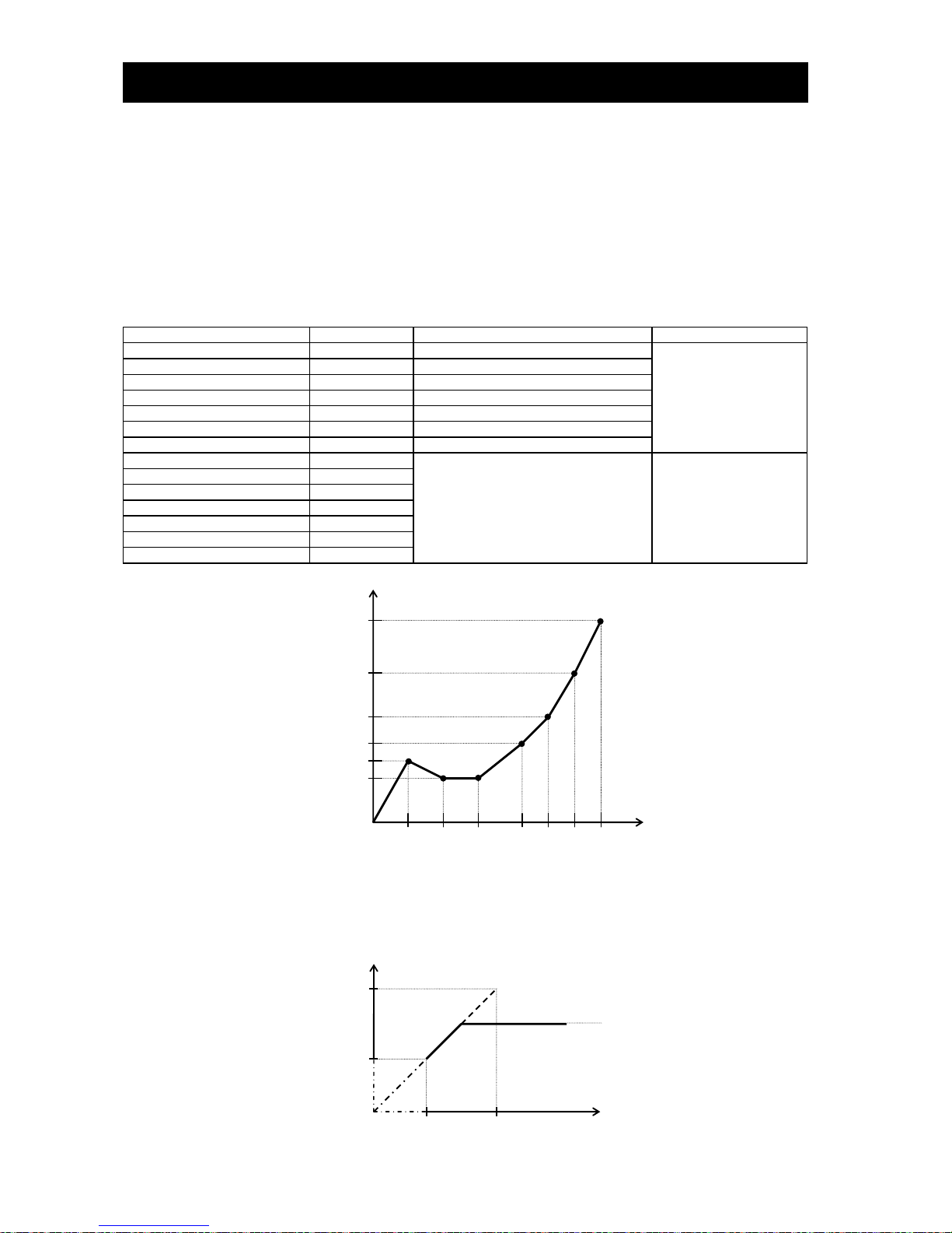
Chapter 4 Explanation of Functions
4-17
(3) Free V/f characteristic setting
The free V/f characteristic setting function allows you to set an arbitrary V/f characteristic by specifying
the voltages and frequencies (b100 to b113) for the seven points on the V/f characteristic curve.
The free V/f frequencies (1 to 7) set by this function must always be in the collating sequence of
"1 ≤ 2 ≤ 3 ≤ 4 ≤ 5 ≤ 6 ≤ 7".
Since all free V/f frequencies are set to 0 Hz as default (factory setting), specify their arbitrary values
(begin setting with free-setting V/f frequency (7)). (The inverter cannot operate with the free V/f characteristic
in the factory setting.)
Enabling the free V/f characteristic setting function disables the torque boost selection (A041/A241),
base frequency setting (A003/A203/A303), and maximum frequency setting (A004/A204/A304).
(The inverter assumes the value of free-setting V/f frequency (7) as the maximum frequency.)
Item
Function code
Data
Description
Free-setting V/f frequency (7)
b112
0.to 400.(Hz)
Setting of the output
frequency at each
breakpoint of the V/f
characteristic curve
Free-setting V/f frequency (6)
b110
0. to free-setting V/f frequency (7) (Hz)
Free-setting V/f frequency (5)
b108
0. to free-setting V/f frequency (6) (Hz)
Free-setting V/f frequency (4)
b106
0. to free-setting V/f frequency (5) (Hz)
Free-setting V/f frequency (3)
b104
0. to free-setting V/f frequency (4) (Hz)
Free-setting V/f frequency (2)
b102
0. to free-setting V/f frequency (3) (Hz)
Free-setting V/f frequency (1)
b100
0. to free-setting V/f frequency (2) (Hz)
Free-setting V/f voltage (7)
b113
0.0 to 800.0(V)
Setting of the output
voltage at each
breakpoint of the V/f
characteristic curve (*1)
Free-setting V/f voltage (6)
b111
Free-setting V/f voltage (5)
b109
Free-setting V/f voltage (4)
b107
Free-setting V/f voltage (3)
b105
Free-setting V/f voltage (2)
b103
Free-setting V/f voltage (1)
b101
(Example)
*1 Even if 800 V is set as a free-setting V/f voltage (1 to 7), the inverter output voltage cannot exceed the inverter
input voltage or that specified by the AVR voltage select.
Carefully note that selecting an inappropriate control system (V/f characteristic) may result in overcurrent during
motor acceleration or deceleration or vibration of the motor or other machine driven by the inverter.
Output voltage (V)
Output frequency (Hz)
f1
f2
f3
f4
f5
f6
f7
0
V2,V3
V1
V5
V6
V7
V4
Voltage that can be output by the
inverter or that was specified by
the AVR voltage select
Output frequency (Hz)
Output voltage (V)
0
f6
f7
V6
V7

Chapter 4 Explanation of Functions
4-18
4.2.18 Torque boost setting
The torque boost setting function allows you to compensate for the
voltage drop due to wiring and the primary resistance of the motor
so as to improve the motor torque at low speeds.
When you select automatic torque boost by the torque boost
selection (A041/A241), adjust the settings of the motor capacity
selection (H003/H203) and motor pole selection (H004/H204)
based on the motor to be driven.
Item
Function code
Data or range of data
Description
Torque boost selection
A041/A241
00
Manual torque boost
01
Automatic torque boost
Manual torque boost value
A042/A242/A342
0.0 to 20.0(%)
Setting of the rate of the boost to the
output voltage (100%)
Manual torque boost frequency
adjustment
A043/A243/A343
0.0 to 50.0(%)
Setting of the rate of the frequency at
breakpoint to the base frequency
Motor capacity
H003/H203
0.20 to 75.0(kW)
Selection of the motor capacity
Motor poles setting
H004/H204
2, 4, 6, 8, or 10 (poles)
Selection of the number of poles of the
motor
Voltage compensation gain
setting for automatic torque
boost
A046/A246
0. to 255.
See Item (2), "Automatic torque
boost."
Slippage compensation gain
setting for automatic torque
boost
A047/A247
0. to 255.
See Item (2), "Automatic torque
boost."
(1) Automatic torque boost
The inverter outputs the voltage according to the settings of the manual torque boost (A042/A242/A342) and manual
torque boost frequency adjustment (A043/A243/A343).
Use the manual torque boost value (A042/A242/A342) to specify the rate of the boost to the voltage (100%) set by the
AVR voltage select.
The set rate of voltage corresponds to the boost voltage that is output when the output frequency is 0 Hz.
When increasing the value of the manual torque boost value, be careful to prevent motor over-excitation.
Over-excitation may result in motor burnout.
Use the manual torque boost frequency adjustment (A043/A243/A343) to specify the rate of the frequency at each
breakpoint to the base frequency (100%).
To switch the settings among the 1st, 2nd, and 3rd settings ("A041 to A043", "A241 to A243", and "A342 and A343"),
assign function "08" (SET) and "17" (SET3) to intelligent input terminals. Use the SET and SET3 signals for switching.
A042/A242/A342
A043/A243/A343
100
Output voltage (%)
Base frequency
(100%)
Output
frequency
A041/A241: Torque boost selection, 1st/2nd motors
A042/A242/A342: Manual torque boost value,
1st/2nd3rd motors
A043/A243/A343: Manual torque boost frequency
adjustment, 1st/2nd/3rd motors
H003/H203: Motor capacity, 1st/2nd motors
H004/H204: Motor poles setting, 1st/2nd motors
Related code

Chapter 4 Explanation of Functions
4-19
(2) Automatic torque boost
When automatic torque boost (data "01") is selected by the torque boost selection (A041/A241), the inverter
automatically adjusts the output frequency and voltage according to the load on the motor.
(During actual operation, the automatic torque boost is usually combined with the manual torque boost.)
When you select the automatic torque boost, adjust the settings of the motor capacity selection (H003/H203) and
motor pole selection (H004/H204) according to the motor to be driven.
If the inverter trips due to overcurrent during motor deceleration, set the AVR function select (A081) to always enable
the AVR function (data "00").
If you cannot obtain the desired operation characteristic by using the automatic torque boost, make the following
adjustments:
Symptom
Adjustment method
Adjustment item
Motor torque is insufficient at low
speed.
(The motor does not rotate at low
speed.)
(1) Increase the voltage setting for manual torque boost step
by step.
A042/A242
(2) Increase the slippage compensation gain for automatic
torque boost step by step.
A047/A247
(3) Increase the voltage compensation gain for automatic
torque boost step by step.
A046/A246
(4) Reduce the carrier frequency setting.
b083
The motor speed falls when a load is
applied to the motor.
Increase the slippage compensation gain for the automatic
torque boost step by step.
A047/A247
The motor speed increases when a
load is applied to the motor.
Reduce the slippage compensation gain for the automatic
torque boost step by step.
A047/A247
The inverter trips due to overcurrent
when a load is applied to the motor.
(1) Reduce the voltage compensation gain for the automatic
torque boost step by step.
A046/A246
(2) Reduce the slippage compensation gain for the automatic
torque boost step by step.
A047/A247
(3) Reduce the voltage setting for the manual torque boost
step by step.
A042/A242
This function cannot be selection for 3rd moter setting.
Manual torque boost valid.

Chapter 4 Explanation of Functions
4-20
4.2.19 DC braking (DB) setting
The DC braking function allows you to apply DC braking to the motor
according to the load on the motor.
You can control DC braking in two ways: the external control through
signal input to intelligent input terminals and the internal control to be
performed automatically when the motor is started and stopped.
Note that the motor cannot be stopped by DC braking if the load on
the motor produces a large moment of inertia.
Item
Function code
Data or range of data
Description
DC braking enable
A051
00
Internal DC braking is disabled.
01
Internal DC braking is enabled.
02
Internal DC braking is enabled. (The braking
operates only with the set braking frequency.)
DC braking
frequency setting
A052
0.00 to 60.00 (Hz)
With internal DC braking enabled, DC braking is
started when the output frequency reaches the
set braking frequency.
DC braking wait
time
A053
0.0 to 5.0 (s)
The DC braking wait time specifies the delay in
starting DC braking after the set braking time
has elapsed or the DB terminal has been turned
on.
DC braking force
during deceleration/
DC braking force for
starting
A054/
A057
CT mode :
0. to 100. (%)<0. to 80.(%)>
VT mode :
0. to 70. (%)<0. to 50.(%)>
"0" specifies the smallest force (zero current);
"100" specifies the largest force (rated current).
DC braking time for
deceleration
A055
0.0 to 60.0 (s)
This setting is valid for the external DC braking
in edge mode or for the internal DC braking.
DC braking/edge or
level detection for
[DB] input
A056
00
Edge mode (See Examples 1-a to 6-a.)
01
Level mode (See Examples 1-b to 6-b.)
DC braking time for
starting
A058
0.0 to 60.0 (s)
This setting is valid for the internal DC braking.
DC braking is started when the motor-start
command is input.
DC braking carrier
frequency setting
A059
CT mode :
0.5 to 15.0 (kHz)<0.5 to 10.0(kHz)>
VT mode :
0.5 to 12.0 (kHz)<0.5 to 8.0(kHz)>
Unit: kHz
(NOTE) <>:applied for 75 to 150kW
(1) Carrier frequency for DC braking
Use the DC braking carrier frequency setting (A059) to specify the carrier frequency for DC braking. But the raking
power reduced is reduced when 5Hz (up to 55kW) or 3Hz (75-150kW) are set as shown below. For detailed
decreasing ratio, "DC braking limiter" is to be referred.
DC braking force limiter(0.4-55kW) DC braking force limiter(75-150kW)
A051: DC braking enable
A052: DC braking frequency setting
A053: DC braking wait time
A054: DC braking force during deceleration
A055: DC braking time for deceleration
A056: DC braking/edge or level detection for
[DB] input
A057: DC braking force for starting
A058: DC braking time for starting
A059: DC braking carrier frequency setting
C001 to C008: Terminal [1] to [8] functions
Related code
DC braking carrier frequency(kHz)
Maximum braking
force (%)
DC braking carrier frequency(kHz)
(80)
VT mode
Maximum braking
force (%)
0
80
100
70
60
50
40
30
20
10
90
3
15
13
11 9 5
7
(70)
(46)
(34)
(22)
(10)
(58)
Maximum braking
force (%)
Maximum braking
force (%)
CT mode
0
80
100
70
60
50
40
30
20
10
90
3
15
13
11 9 5
7
(75)
(46)
(34)
(22)
(10)
CT mode
VT mode
0
80
100
70
60
50
40
30
20
10
90
10
9
7
(60)
(40)
(20)
(10)
5
3
0
80
100
70
60
50
40
30
20
10
90
10
9
7
(50)
(25)
(10)
5
3
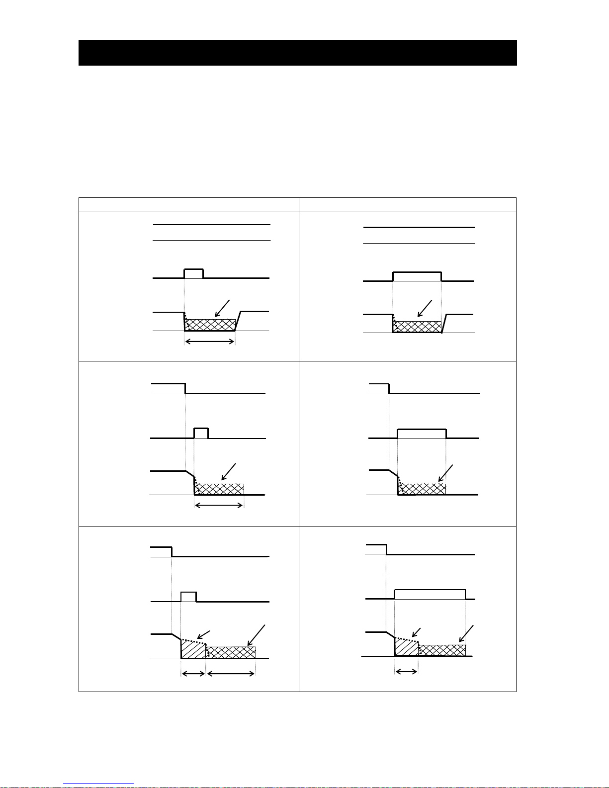
Chapter 4 Explanation of Functions
4-21
(2) External DC braking
Assign function "07" (DB) to terminal function (C001 to C008).
Turn the DB terminal on and off to control the direct braking, regardless of the setting of DC braking enable (A051).
Adjust the braking force by adjusting the DC braking force setting (A054).
When you set the DC braking wait time (A053), the inverter output will be shut off for the set period of delay, and the
motor will run freely during the period. DC braking will be restarted after the delay.
When setting the DC braking time with function "A055" or for the DC braking operation via the DB terminal, determine
the length of time in consideration of the heat generation on the motor.
Select the braking mode by the DC braking/edge or level detection for [DB] input (A056), and then make any other
necessary settings suitable for your system.
(a) Edge mode (A056: 00)
(b) Level mode (A056: 01)
(Example 1-a)
(Example 1-b)
(Example 2-a)
(Example 2-b)
(Example 3-a)
(Example 3-b)
FW
DB
Output
frequency
FW
DB
Output
frequency
FW
DB
Output
frequency
FW
DB
Output
frequency
FW
DB
Output
frequency
FW
DB
Output
frequency
A055
DC braking
DC braking
A055
DC braking
DC braking
A053
Free running
A055
DC braking
A053
Free running
DC braking

Chapter 4 Explanation of Functions
4-22
(3) Internal DC braking (A051: 01)
You can apply DC braking to the motor even without entering braking signals via the DB terminal when the inverter
starts and stops. To use the internal DC braking function, specify "01" for the DC braking enable (A051).
Use function "A057" to set the DC braking force for starting, and use function "A058" to specify the DC braking time for
starting, regardless of the braking mode selection (edge or level mode). (See Example 4-a and 4-b.)
Set the braking force for periods other than starting by using the DC braking force setting (A054).
Set the output frequency at which to start DC braking by using the DC braking frequency setting (A052).
When you set the DC braking wait time (A053), the inverter output will be shut off when the output frequency reaches
the setting of "A052" after the operation command (FW signal) is turned off, and the motor will run freely for the delay
time set by "A053". DC braking will be started after the delay (A053).
The internal DC braking operation to be performed when the operation command is switched from the stop command
to the start command varies depending on the braking mode (edge or level mode).
Edge mode: The DC braking time setting (A055) is given priority over operation commands, and the inverter
performs DC braking according to the setting of "A055". When the output frequency reaches the
setting of "A052" the inverter performs DC braking for the time set for "A055". Even if the stop
command is input during DC braking, DC braking continues until the time set for "A055" elapses. (See
Example 5-a and 6-a.)
Level mode: Operation commands are given priority over the DC braking time setting. The inverter follows
operation commands, regardless of the DC braking time setting (A055). If the start command is input
during DC braking, the inverter starts the normal motor operation, regardless of the DC braking time
setting (A055). (See Example 5-b and 6-b.)
(a) Edge mode
(b) Level mode
i) (Example 4-a) when the start command is input:
i) (Example 4-b) when the start command is input:
ii) (Example 5-a) when the stop command is input:
ii) (Example 5-b) when the stop command is input:
ii) (Example 6-a) when the stop command is input:
ii) (Example 6-b) when the stop command is input:
FW
Output
frequency
FW
Output
frequency
FW
Output
frequency
FW
Output
frequency
FW
Output
frequency
FW
Output
frequency
A058
DC braking
A058
DC braking
A053
Free running
A055
A052
DC braking
DC braking
A053
A055
A052
Free running
A052
A055
DC braking
A052
A055
DC braking

Chapter 4 Explanation of Functions
4-23
(4) Internal DC braking (triggered only when the output frequency reaches a set frequency) (A051: 02)
You can also operate the internal DC braking function so that DC braking is applied to the motor when the inverter
output frequency falls to the DC braking frequency setting (A052) or below.
When the internal DC braking function is used in this mode, the external DC braking described in Item (2) and the
internal DC braking described in Item (3) cannot be used.
In this mode, DC braking operates only when the operation command signal is on (i.e., the start command is input).
The inverter starts DC braking when both the frequency set by the frequency command and the current output
frequency fall to the DC braking frequency setting (A052) or below. (See Example 7-a.)
When the frequency set by the frequency command increases to the "setting of 'A052' + 2 Hz" or more, the inverter
stops DC braking and restores its normal output. (See Example 7-a.)
If the frequency set by the frequency command is 0 Hz when the start command is input via an analog input terminal,
the inverter will start operation with DC braking because both the frequency set by the frequency command and
current output frequency are 0 Hz. (See Example 7-b.)
If the operation command signal (start command) is turned on when the frequency command specifies a frequency
larger than the DC braking frequency (A052), the inverter will start operation with the normal o utput.
(Example 7-a) (Example 7-b)
How the inverter returns to the normal output varies depending on the setting of the DC braking/edge or level
detection for [DB] input (A054).
(a) Edge mode
(b) Level mode
ON
Operation
command
Frequency
command
Output
frequency
Operation
command
Frequency
command
Output
frequency
Operation
command
Frequency
command
Output
frequency
Operation
command
Frequency
command
Output
frequency
A052
ON
A052
A052
ON
A053
A052
ON

Chapter 4 Explanation of Functions
4-24
4.2.20 Frequency upper limit setting
The frequency upper limit setting function allows you to place upper and
lower limits on the inverter output frequency.
This function restricts the input of frequency commands that specify any
frequencies outside the upper and lower limits.
Always set the upper limit before setting the lower limit. Also, be sure to keep the frequency upper limit (A061/A261)
larger than the frequency lower limit (A062/A262).
Be sure that upper limit/lower limit does not exceed Maximum frequency (A004/A204/A304).
Be sure to set output frequency (F001) and multiple speed 1 to 15 (A021 to A035) in between uppelimit and lower
limit.
If 0 Hz is set for the frequency upper and lower limits, they will not operate.
The frequency limit setting function is disabled when the 3rd control system is selected.
Item
Function code
Range of data
Description
Frequency upper
limit setting
A061/A261
0.00 or a frequency more than the
frequency lower limit setting up to the
maximum frequency (Hz)
Setting of the upper limit of the
output frequency
Frequency lower limit
setting
A062/A262
0.00 or a frequency not less than the
starting frequency up to the frequency
upper limit setting (Hz)
Setting of the lower limit of the
output frequency
(1) When the O-L or OI-L terminal is used:
(2) When the O2-L terminal is used:
If the frequency lower limit is used with the frequency command input via the O2-L terminal, the motor speed with 0 V
input will be fixed to the frequency setting of the frequency lower limit (A062) for forward rotation or the frequency
setting of the frequency lower limit (A062) for reverse rotation as shown below.
(a) When operation commands are input via the control circuit terminal block (A002: 01)
Terminal
Motor speed with 0 V input via O2 terminal
FW(ON)
Frequency setting by A062 for forward rotation
RV(ON)
Frequency setting by A062 for reverse rotation
(b) When operation commands are input from the digital operator (A002: 02)
F004
Motor speed with 0 V input via O2 terminal
00
Frequency setting by A062 for forward rotation
01
Frequency setting by A062 for reverse rotation
A061/A261: /Frequency upper limit setting,
1st/2nd motors
A062/A262: Frequency lower limit setting,
1st/2nd motors
Related code
A062
A061
Output frequency (Hz)
Frequency command
0 V
4 mA
10 V
20 mA
Maximum frequency
A004/A204
If 0 V or 4 mA is input as the frequency command
when a frequency lower limit has been set for the
frequency lower limit setting (A062), the inverter will
output the set frequency.
A062
A061
A004/A204
A062
A061
10 V
-10 V
Maximum frequency
A004/A204
Reverse rotation
Forward rotation
Maximum frequency

Chapter 4 Explanation of Functions
4-25
4.2.21 Jump frequency function
The jump frequency function allows you to operate the inverter so that it
avoids the resonant frequency of the machine driven by the same.
Since the inverter avoids the motor operation with a constant output
frequency within the specified range of the frequencies to jump when the
jump frequency function is enabled, you cannot set any inverter output
frequency within the specified range of the frequencies to jump.
Note that, while the inverter is accelerating or decelerating the motor,
the inverter output frequency changes continuously according to the set
acceleration/deceleration time.
You can set up to three frequencies to jump.
Item
Function code
Range of data
Description
Jump (center) frequency
settings, 1st/2nd/3rd settings
A063/A065/
A067
0.00 to 400.0 (Hz) (*1)
Setting of the center frequency of the
frequency range to be jumped
Jump (hysteresis) frequency
width settings, 1st/2nd/3rd
settings
A064/A066/
A068
0.00 to 10.00(Hz)
Setting of the half bandwidth of the
frequency range to be jumped
*1 Setting of 0 Hz disables the jump frequency function.
4.2.22 Acceleration stop frequency setting
The acceleration stop frequency setting function allows you to make the
inverter wait, upon starting the motor, until the slipping of the motor
becomes less when the load on the motor causes a large moment of
inertia.
Use this function if the inverter has tripped because of overcurrent when starting the motor.
This function can operate with every acceleration pattern, regardless of the setting of the acceleration curve selection
(A097).
Item
Function code
Range of data
Description
Acceleration stop frequency
setting
A069
0.00 to 400.0(Hz)
Setting of the frequency at which to stop
acceleration
Acceleration stop time
frequency setting
A070
0.0 to 60.0(s)
Setting of the length of time to stop
acceleration
A063: Jump (center) frequency setting 1
A064: Jump (hysteresis) frequency width
setting 1
A065: Jump (center) frequency setting 2
A066: Jump (hysteresis) frequency width
setting 2
A067: Jump (center) frequency setting 3
A068: Jump (hysteresis) frequency width
setting 3
Related code
A063
A065
A067
A064
A064
A066
A066
A068
A068
Output frequency
Frequency command
A069: Acceleration stop frequency setting
A070: Acceleration stop time frequency setting
Related code
A070
A069
Output frequency
Frequency command

Chapter 4 Explanation of Functions
4-26
4.2.23 PID function
The PID function allows you to use the inverter for the process control
on fluid flow, airflow, and pressure.
To enable this function, specify "01 lenabled" or "02 inverted data
output enabled" for function "A071".
You can disable the PID function with an external signal during the PID
operation. For this purpose, assign function "23" (PID terminal:
disabling PID operation) to an intelligent input terminal. Turning the
PID terminal on disables the PID function and makes the inverter
perform the normal output.
With the PID function, you can limit the PID output according to various
conditions.
Refer to maximum frequency (4.2.10), frequency limiter (4.2.20), PID
rariation range (A078).
Item
Function code
Data or range of data
Description
PID Function Enable
A071
00
Disabling the PID operation
01
Enabling the PID operation
02
Enabling inverted-data output
PID proportional gain
A072
0.2 to 5.0
Proportional gain
PID integral time constant
A073
0.0 to 3600.(s)
Integrated gain
PID derivative gain
A074
0.00 to 100.0(s)
Derivative gain
PV scale conversion
A075
0.01 to 99.99
Scale for unit conversion of PID feedback data
PV source setting
A076
00
OI-L: 4 to 20 mA
01
O-L: 0 to 10 V
02
RS485 communication
03
Frequency command as pulse train
10
Operation result (*1)
Output of inverted PID
deviation
A077
00
Disabling the inverted output
01
Enabling the inverted output (deviation
polarity inverted)
PID variation range
A078
0.0 to 100.0(%)
Range of PID data variation with reference to
the target value
PID feed forward selection
A079
00
Invalid
01
O-L : 0-10V
02
OI-L : 4-20mA
03
O2-L : -10-10V
PID deviation level setting
C044
0.0 to 100.0(%)
Level to determine the OD signal output
Off level of feedback
comparison signal
C052
0.0 to 100.0(%)
Level to determine the FBV signal output
Onlevel of feedback
comparison signal
C053
0.0 to 100.0(%)
Level to determine the FBV signal output
(*1) refer 4.2.12 Frequency operation function
(1) Basic configuration of PID control
Kp: Proportional gain T i: Integral time Td: Derivative time s: Operator ε: Deviation
fs
M
=
+
-
Kp(1+ +Td・S)
1
Ti・S
Target value
0 to 10 V
4 to 20 mA
Deviation
(ε)
Feedback 0 to 10 V
4 to 20 mA
Operation
quantity
Normal control
by the inverter
Transducer
Sensor
+
+
Feed Forward invalid
0-10V
0-20mA
-10-10V
A001: Frequency source setting
A005: [AT] selection
A006: [O2] selection
A071: PID Function Enable
A072: PID proportional gain
A073: PID integral time constant
A074: PID derivative gain
A075: PV scale conversion
A076: PV source setting
A077: Output of inverted PID deviation
A078: PID variation range
A079: PID feed forward selection
d004: Process variable (PV), PID feedback
monitoring
C001 to C008: Terminal [1] to [8] functions
C021 to C025: Terminal [11] to [15] functions
C044: PID deviation level setting
C052: Off level of feedback comparison signal
C053: Onlevel of feedback comparison signal
Related code
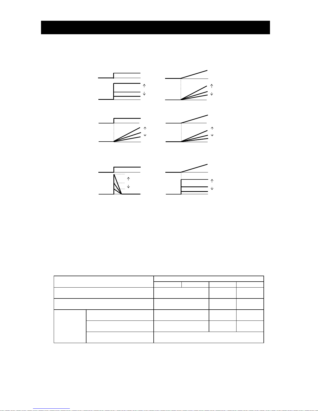
Chapter 4 Explanation of Functions
4-27
(2) PID operation
1) P operation
The proportional (P) operation stands for the operation in which the change in operation quantity is in proportion to
the change in target value.
2) I operation
The integral (I) operation stands for the operation in which the operation quantity increases linearly over time.
3) D operation
The derivative (D) operation stands for the operation in which the operation quantity changes in proportion to the
rate of change in the target value.
The PI operation is a combination of the P operation 1) and I operation 2). The PD operation is a combination of the
P operation 1) and D operation 3). The PDI operation is a combination of the P operation 1), I operation 2), and D
operation 3).
(3) PV source setting
Select the terminal to be used for the feedback signal with the PV source setting function (A076).
The terminal to input the target value follows the frequency source setting (A001). The terminal selected by the PV
source setting (A076) is excluded.
If the control circuit terminal block ("01") has been specified for frequency source setting "A001", the setting of AT
selection (A005) is invalid.
The table below shows how the PID target value is selected according to the setting of "A006" when the analog input is
selected by the PV source setting and the control circuit terminal block ("01") is specified for "A001".
PV source setting (A076)
PID target value
A006=00
A006=01
A006=02
A006=03
00 (OI-L)
O + O2
(non-reversible)
O + O2
(reversible)
O
01 (O-L)
OI + O2
(non-reversible)
OI + O2
(reversible)
OI
10 (operation
result)
Operation targets include the
input to the OI terminal.
O + O2
(non-reversible)
O + O2
(reversible)
O
Operation targets include the
input to the O terminal.
OI + o2
(non-reversible)
OI + O2
(reversible)
OI
Operation targets are the inputs to
the OI and O terminals.
O2
(reversible)
A072
A072
Change in steps
Target value
Operation quantity
Linear change
Large
Small
Large
Small
A073
A073
Target value
Operation quantity
Small
Large
Small
Large
A074
A074
Target value
Operation quantity
Large
Small
Large
Small

Chapter 4 Explanation of Functions
4-28
When you specify the 02 RS485 communication for the PV source setting (A076), transfer data as described below.
1) When the ASCII mode is selected (C078 = 00)
Use the 01 command for data transfer. To transfer feedback data, set the most-significant byte of frequency data
to "1".
Example: When transmitting the frequency data specifying 5 Hz
The data to be transmitted consists of six bytes, indicating a value 100 times as large as the set
frequency value. "000500"
Change the most-significant byte to "1". "100500"
Convert the data to ASCII format. "31 30 30 35 30 30"
Note: In ASCII mode, the unit of setting is always frequency (Hz).
2) When the Modbus RTU mode is selected (C078 = 01)
Write the setting data (on the assumption that "10000" indicates 100%) to register address 0006h.
Register
No.
Function name Function code
Readable/writable
(R/W)
Monitored data or setting
Data
resolution
0006h
PID feedback -
R/W
0 to 10000
0.01 [%]
Note: This register is readable and writable. However, this register can be read only when Modbus RTU has
been specified as the communication mode for PID feedback. It cannot be read with other settings.
- When pulse train input is specified for PID feedback, the input pulse train frequency (Hz) is converted to a percentage
(with maximum frequency corresponding to 100%) and fetched as the feedback.
For the pulse train input frequency, see Section 4.3.21.
(4) Feed forward selection
- Select the terminal to be used for the feed forward signal through PID feed forward selection (A079).
- Even if the terminal selected for the target or feedback data is also selected for the terminal by A079, the terminal
functions according to the setting of A079.
- Specifying the value to disable selection for A079 disables feed forward control.
(5) Output of inverted PID deviation
Some sensor characteristics may cause the polarity of the deviation of feedback data from the target value to be
inconsistent with the inverter operation command. If the inconsistency occurs, specify "01" for function "A077" to
invert the polarity of the deviation.
Example: When controlling the compressor for a refrigerator
Assume that the temperature and voltage specifications of the temperature sensor are -20°C to +100°C and 0 to 10 V
and the target value is 0°C.
If the current temperature is 10°C and the inverter is under the normal type of PID control, the inverter will reduces
the output frequency because the feedback data is larger than the target value.
In such a case, specify "01" for function "A077" to invert the feedback deviation. Then, the inverter will increase the
output frequency.
(6) Limitation on PID variation range
You can limit the PID output to within a specific range with reference to the target value.
To use the PID variation limit function, set the PID variation range (A078).
(Set a value on the assumption that the maximum frequency corresponds to 100%.)
The variation of PID output is limited within ±"value of A078" from the target value.
(Setting "0.0" for the PID variation range [A078] disables the PID variation limit function.)
This function is deactivated when 0.0 is set on A078.
(7) Output of inverted PID deviation
If the inverter is under the normal PID control and the PID operation result is a negative value, the frequency
command to the inverter will be limited to 0 Hz. However, when "02" (enabling the inverted output) is set for the PID
PID
operation
-1
A077
PID target value
PID feedback data
PID output (%)
PID target value
PID output range
PID variation range (A078)
PID variation range (A078)
Time (s)

Chapter 4 Explanation of Functions
4-29
Function Enable (A071), the PID operation result to be output to the inverter is inverted if the result is a negative
value.
Setting "02" for function "A071" disables the PID variation limit (A078) described above.
(8) PID gain adjustment
If the inverter response is unsteady when the PID control function is used, try to adjust gain settings as follows:
- If the feedback data does not quickly follow the change in the target value Increase the P gain (A072).
- If the feedback data is unstable although it quickly follows the change in the target value Reduce the P gain
(A072).
- If considerable time is required until the feedback data matches the target value Reduce the I gain (A073).
- If the feedback data fluctuates unsteadily Increase the I gain (A073).
- If the inverter response is slow even after the P gain is increased Increase the D gain (A074).
- If the feedback data becomes fluctuant and unsteady when the P gain is increased Reduce the D gain (A074).
(9) Maximum PID deviation output (OD)
You can set the PID deviation level (C044) for PID control. When the PID deviation (ε) exceeds the level set as the level
"C044", the signal is output to an intelligent output terminal.
A value from 0 to 100 can be set as the level "C044". The range of values corresponds to the range of target values
from 0 to the maximum.
To use this output function, assign function "04" (OD) to one of the terminal functions C021 to C025 or the alarm relay
terminal function C026.
(10) Feedback comparison signal
A feedback comparison signal can be output to an intelligent output terminal when the PID feedback data exceeds the
specified range.
To use this signal output function, assign function "31" (FBV) to one of the terminal functions C021 to C025 or the
alarm relay terminal function C026.
(11) Process variable (PV), PID feedback monitoring (d004)
You can monitor the PID feedback data on the inverter.
When you set a PV scale conversion with function "A075", the value to be displayed as the monitored data can be the
product of the feedback data and the scale.
"Monitored value" = "feedback data (%)" x " PV scale conversion (A075)"
(12) Reset of PID integration (PIDC)
This reset function clears the integral result of PID operation.
To use this function, assign function "24" (PIDC) to one of the terminal functions C001 to C008.
The integral result is cleared each time the PIDC terminal is turned on.
Never turn on the PIDC terminal during the PID operation. Otherwise, the inverter may trip because of overcurrent. Be
sure to disable the PID function before turning on the PIDC terminal.
FW
FBV
ON
OFF
OFF
ON
PID feedback
C052 (off level)
C053 (on level)
Time
 Loading...