

Hitachi SJ100-002NFE, SJ100-007NFE, SJ100-004NFE, SJ100-005NFE, SJ100-011NFE Quick Reference Manual
...Page 1
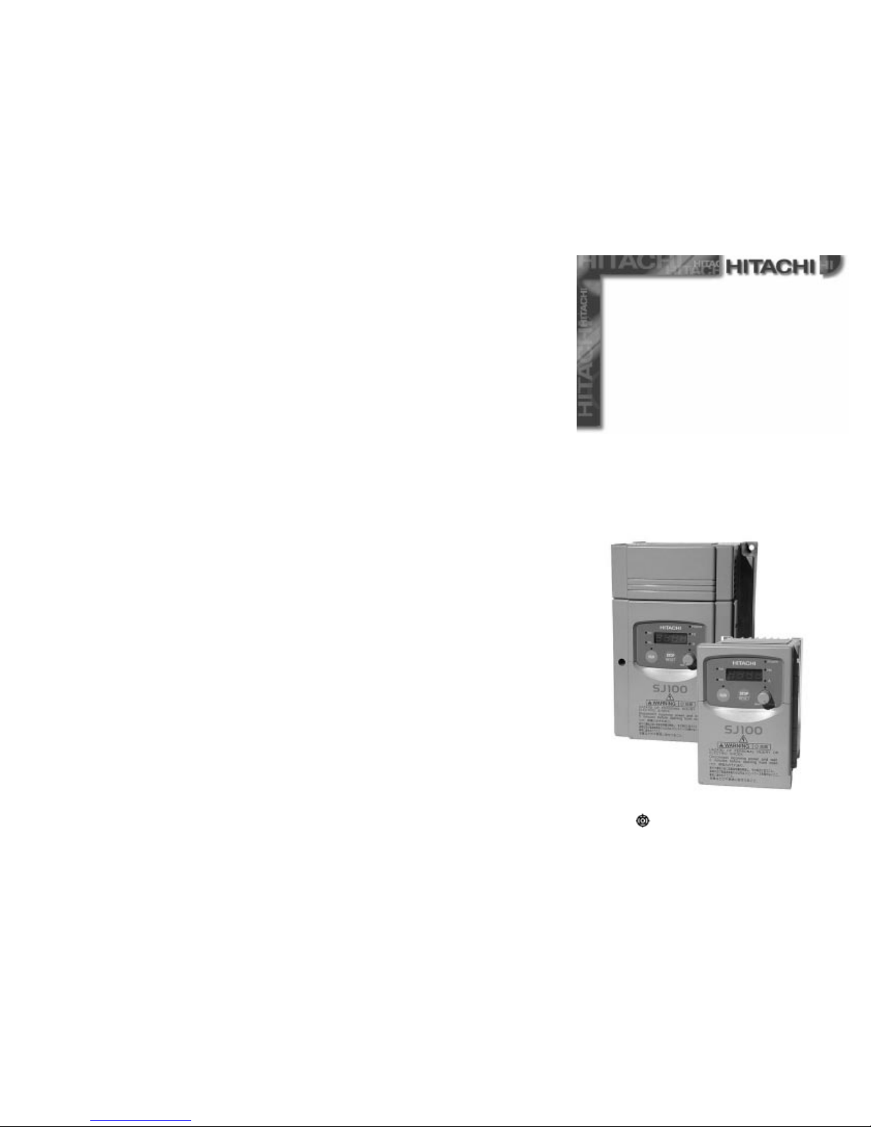
Hitachi Europe GmbH
QQUUIICCKK RREEFFEERREENNCCEE GGUUIIDDE
E
Hitachi Inverter
SJ100 Series
Page 2

Table of Contents
Part 1 / 2 3
Description of SJ100 Display ................................................ 3
Operation procedure (example for the digital operator)............ 3
Setting extended functions (example for group A extended
functions) .............................................................................. 4
Protective Functions............................................................... 5
SJ100 data setting values ....................................................... 5
Drive keypad display sequence .............................................. 5
Part 2 / 2 9
CE-EMC Installation, Guidelines............................................ 9
WIRING EXAMPLES: ...........................................................11
Set value 4..20mA and thermistor ........................................11
Fixed set values; FA1 output and RUN output .....................11
Flow control .......................................................................11
Externa l dimensions and terminal po s itions ............................12
TECHNICAL SPECIFICATIONS: .........................................13
SJ100, 200V series .............................................................13
SJ100, 400V series .............................................................14
© 1999 Hitachi Europe Ltd.
Am Seestern 18
D-40547 Düsseldorf
Phone: +49 (0) 2 11 – 52 83 –0
Fax: +49 (0) 2 11 – 52 83 –649
e-Mail: [email protected]
Internet: www.hitachi-ds.com
Page 3

FUNC
RE
ET
--
--
--
--
After the data is
changed, press the
STR key to save data
[FUNC key] ... This key switches
between the parameter area, data
area, and extended function area.
Each time the key is pressed, the
display changes as follows:
Pressing the FUNC key
leaves data unchanged
[UP key, DOWN key] ... These keys change the
values of data area, and parameters:
Output fr equ e nc y
monitor
Output current
monitor
Running direction
monitor
PID feedback
monitor
Input terminal
status
Output terminal
status
Scaled output
frequency
Trip monitor
Trip history
monitor
Set the output
frequency
Set acceleration
time 1
Set deceleration
time 1
Set motor
direction
Group A ext ended functi ons
Group B extended functi ons
Group C extended functi ons
[START key] ... This key starts
the SJ100 inverter.
The set value of
F004
deter-
mines forward or rev e rse run.
[STOP key] ... T his key
stops the SJ100 inverter.
When a trip occurs, this key
becomes the RESET ke
y
Group H ext ended functi ons
Set acceleration
time 1 (2. settin
g)
Set deceleration
time 1 (2. setting)
When an extended function is to be used, select the
extended function group from , ,
, or by using the two keys
and so as to enter the extended function mode.
Extended function
parameter number
Extended function data
Return to extended
function pa r a met e r
and memorize
Return to extended
function pa r a met e r an d
do NOT memorize
Explanati o n of dis p lay at pow er on
When the inverter is turned on, the display returns to what was displayed when the power
was last turned off (exc ept in the extended function mode).
Setting extended functions (example for group A extended functions
)
--
A -- b --
C --
Extended fu nctions ar e
entered fr om
A - -
using
the FUNC key. Following this, the function
parameter number is
displayed f o r w hic h
data had been entered
last.
After changes to data
have been made, the
FUNC key or STR key
must be press ed. When
the FUNC key is being
pressed onc e mor e,
control is returned back
to
A - -
.
H --
Trip Contents Display
Overcurrent
protection
When the output of the inverter is short circuited,
the motor is locked, or a heavy load is suddenly
applied, and the inverter output current exceeds a
predetermined level, the inverter is shut off.
C
onst. speed
:
E001
At decelerat
.:
E002
At accelerat
.:
E003
At the others:
E004
Overload
protection
When a motor overload is detected by the electronic
thermal function, the inverter is shut off.
E005
Braking resistor overload
When the operation of the braking resistor exc eeds a
certain time duration, the inverter is shut off.
E006
Overvoltage
protection
When the inverter DC bus voltage exceeds a predetermined level due to regenerative energy from the
motor, this trip occures and the inverter is shut off.
E007
(NOTE 1)
When the inverter memory has a prob lem due to
noise or excessive temperature rise, this trip occurs
and the inverter is shut off.
E008
Undervo ltage
protection
A decrease of DC bus voltage may result in improper
function of the control unit. It may also cause motor
heating and low torque. The inverter is shut off when
the DC bus voltage goes below a certain level.
E009
CT error When a large noise source is near the inverter or an
abnormality occurs on built-in CT, inverter output is
cut off.
E010
CPU error Malfunction or abnormality of the CPU. The inverter
is shut off.
E011
E022
External trip A trip signal from external equipment shuts off the
inverter. It is necessary to assign the external trip to
an intelligent terminal.
E012
USP error Indicates an error when power is turned on while the
inverter run is enabled (with USP function selected).
E013
Ground f ault
protection
The inverter is protect ed by detecti on of ground
faults between the drive output and the motor at
power on. Pr otection is for the inverter only and not
for humans.
E014
Input
overvoltage
When the input voltage is higher than a specified
value, it is detected and 100 seconds after power is
turned on, the inverter is shut off.
E015
Thermal
protection
When the temperature of the inverter module is beyond specification, the built-in thermal sensor detects
the temperature and the inverter is shut off.
E021
PTC error W hen the resistance value of the external thermistor
is too large, the equipment detects the abnormal
condition of the thermistor and then shuts off the
inverter (when PTC function is selected).
E035
Waiting
(
undervoltage
)
Waiting with the output turned off, because the
inverter receiving voltage has dropped.
_ _ U
SJ100
This information is written on
the nameplate located on the
right side of t he S J1 00 inv e rt er.
Display Function
Standard Setting
Set Value
d 01 ..
.. d 09
Display functions Refer to page 4
F 01
Set output frequency (Hz) 0.0
F 02
Set acceleration 1 (s) 10.0
F202
Set acceleration 1 (s), 2. setting 10.0
F 03
Set deceleration 1 (s) 10.0
F203
Set deceleration 1 (s), 2. setting 10.0
F 04
Set motor direction 00 (rechts)
A --
Set extended function group A
b --
Set extended function group B
C --
Set extended function group C
H --
Set extended function group H
Refer to pa ges 6 th ro ug h 8
Mfg.No.
Protective Functions
The SJ100 series inverter will trip on overcurrent, overvoltage and undervoltage to protect the
inverter.The output is shut down and the motor runs free. This condition is held until it is reset.
SJ100 data setting values
SJ100 inver t e rs pro vide many fu nc ti o ns w ho se pa r a met e r s c an be
set by the user. It is recommended that the parameters that have been set by the user be recorded
Drive keypad display sequence
N
OTE
1: If an EEPROM error occurs, be sure to observe ist value. If power is turned off while the
[RS] input terminal is held ON, the EEPROM error occurs when power is turned back on.
in order to speed the
investigation and repair in the event of
a failure.
Power Lamp
Power Lamp of
Control Circuit.
Hz or A Lamp
Hz or A lamp is on
during d isplay of
frequency or current.
Potentiometer
This potentiometer
sets the frequency (the
lamp is on when the
potentiometer is
available for speed
setting).
STR Key
Press this key after
setting data and
parameters to store
them in memory.
UP/+ Key, DOWN/- Key
These keys are used to change data and parameters
FUNC Key
This key is used
for setting up data
and paramet er s.
RUN Key
This key is used for
starting. (When
terminal run is
selected this key does
not functi o n a nd t he
lamp is off. The lamp
is on when this key is
PRG Lamp
This lamp is on
while a parameter is
being set.
RUN Lamp
This lamp is on when
the inverter is
running or the run
Monitor (LED Display)
This display shows frequency,
motor current, DC voltage,
motor direction, and parameters.
STOP Key
This key is us ed f or st op pi n g
the motor or resetting errors or
trips. (When the keypad is
selected, this key is functional;
non-functional using remote).
MIN MAX
STOP
RESET
HzRUN
PRG
POWER
HITACHI
HITACHI IN V E RTER
SJ100 SERIES
QUICK REFERENCE GUIDE (Part 1/2)
Single phas e inpu t 200V clas s
Three phase i npu t 200V clas s
Three phase i npu t 400V clas s
Hz
Turn
p
ower on.
Data is
stored
Press
continuousl
y
Data is
stored
Start
run
(Motor operates)
Monitoring
actual output
frequenc
y
Extended
function of
A Grou
p
Operation procedure (example for the digital operator)
--
--
Data is stored
Frequenc y s et value set by
function
F 01
(instead of
analog input
)
Setting frequency to 60Hz
Starting command via RUN key
(instead of terminal FW/RV)
3 4 5
Page 4
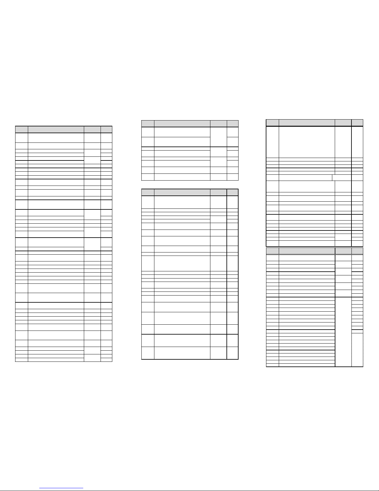
Display Function
Standard
Setting
Set
Value
A 01
Frequenc y S o ur c e sett ing
00-Potentiometer 01-Termina l O/OI
02-Functions
F 01
/
A 20
01
A 02
Run command so u r ce sett ing
01-Terminal FW/RV 02-RUN key
01
A 03
Base frequency setting
A203
Base frequency sett ing (2. setting)
50.0
A 04
Maximum frequ ency set t i ng
A204
Maximum fre qu e ncy setti ng (2 . setting)
50.0
A 11
External frequency setting start point 0
A 12
External frequency setting end point 0
A 13
External frequency setting start point bias (in %) 0
A 14
External frequency setting end point bias (in %) 100
A 15
External frequency start pattern setting
00-Per
A11
and
A13
01-0Hz
01
A 16
Time constant of the filter for analog inputs 8
A 20 –
A 35
Multispeed frequency setting All are
0.0Hz
A 38
Jog freque nc y setting 1.0
A 39
Jog stop mode
00-Freerun 01-Deceleration
02-DC brake
00
A 41
Torque boost selection method
00-Manual 01-Auto mat ic
A241
Torque boost selection method (2. setting)
00
A 42
Value of manua l torque boo st setting 11
A242
Value of manua l torque boo st setting (2. setting) 1 1
A 43
Manual torque boost frequency adjustment (in %)
A243
Manual torque boost frequency adjustment (i n %)
(2. setting)
10.0
A 44
V/F characteristic setting
00-Constant to r qu e
01-Variable t orque 02-SLV
A244
V/F characteristic setting (2. setting)
02
A 45
V-Gain setting (in %) 100
A 51
Selection of DC braking operation
00-NO 01- YES
00
A 52
DC braking freque ncy setting 0.5
A 53
DC braking waiting time setting 0.0
A 54
DC braking force setting 0
A 55
DC braking time setting 0.0
A 61
Frequency upper limit sett ing 0.0
A 62
Frequency lower limit sett ing 0.0
A 63,
A 65,
A 67
Jump freque ncy setti ng 0 .0
A 64,
A 66,
A 68
Jump frequ ency width setting 0.5
A 71
Selection of PID control
00-NO 01- YES
00
A 72
P (proportional) gain setting 1.0
A 73
I (integral) gain setting 1.0
A 74
D (differentia l) gain setting 0.0
A 75
Scale conversion of PID control sett ing 1.00
A 76
Feedback signal location setting
00-Current 01-Vo ltag e
00
A 81
Selection of AVR function
00-Available 01-N ot ava ila ble
02-Not available at deceleration
02
A 82
Selection of voltage of AVR function for the
motor
FE:230/400
FE:230/460
A 92
Second acceleration time setting
A292
Second acceleration time setting (2. setting)
15.0
A 93
Second deceleration time setting
A293
Second deceleration time setting (2. setting)
15.0
(Table to b e cont i nued on next pag e)
Displ
ay
Function
Standard
Setting
Set
Value
b 01
Selection of restart mode
00-Alarm 01-0.0Hz restart
02-Motor speed match restart
03-Motor speed match restart /decel to stop
00
b 02
1.0
b 03
Retry waiting time 1.0
b 12
Level of electronic thermal setting
b212
Level of electronic thermal setting (2. setting)
Rated current
of inverter
b 13
Selection of electronic thermal characteristic
00-Reduced torque 01-Constant torque
01
b213
Selection of electronic thermal characteristic
(2. setting)
01
b 21
Selection of overload limit operation mode
00-NO 01-Accel & constant speed
02-Constant speed
01
b 22
Level of overload limit setting
times 1.25
b 23
Rate of deceleration at overload restriction 1.0
b 31
Selection of software lock mode
00-Termina l, no change
01-Terminal, frequency change
02-Keypad, no chan ge
03-Keypad, frequency change
01
b 81
Analog meter adjustment 80
b 82
Start frequency adjustment 0.5
b 83
Carrier frequency setting (kHz) 5.0
b 84
Initialization will 00-Clear trip history
-
00
b 85
Selection of initialized data
-FE
1 -F
2
b 86
Frequency converted value setting 1.0
b 87
STOP key active in terminal mode
00-YES 01-NO
00
b 88
Selection of operation when FRS signal is
cancelled
00-Restart at 0 Hz 01-Restart at motor speed
00
b 89
Selection of contents of remote display
01-Frequency 02-Current 03-Direction
04-PID feedback 05-Input terminal status
06-Output terminal status 07-Scaled frequency
01
b 90
Rate of use (in %) of the regenerative braking
resistor du r in g 100 seconds
(00= braking resistor not active)
00
b 91
Deceleration mode selection when using the
STOP key
00-Deceleration stop
01-Free run stop (FRS)
00
b 92
Fan ON/OFF selection
00-Fan is always on
01-Fan is only on if the inverter/motor
is running
00
(Continued f ro m pr e vio us p ag e)
Displ
ay
Function
Standard
Setting
Set
Value
A 94
Selection of method to enable second
acceleration/deceleration (acc2/dec2)
00-Termina l 2CH 01-
A 95
/
A 96
A294
Selection of method to enable second
acceleration/deceleration (acc2/dec2)
(2. setting)
00
A 95
Changed frequency from acc1 to acc2 setting
A295
Changed frequency from acc1 to acc2 setting
(2. setting)
0.0
A 96
Changed frequency from dec1 to dec2 setting
A296
Changed frequency from dec1 to dec2 setting
(2. setting)
0.0
A 97
Pattern of acceleration setting
00-Linear 01-S-curve
00
A 98
Pattern of deceleration setting
00-Linear 01-S-curve
00
i
Function
Standard
Setting
Set
Value
C 01
Function of input terminal 1
00-FW (Forward run) 01-RV (Reverse run)
02-CF1 (Multispeed 1) 03-Multispeed 2
-
-
-
-
-
-
-
-
-
-
-
-
-
-
nal 5) 27-UP (remote control acceleration)
28-DWN (remote control deceleration)
00
C 02
Function of input terminal 2 (See
C 01
)01
C 03
Function of input terminal 3 (See
C 01
)
-
-
C 04
Function of input terminal 4 (See
C 01
)
-
-
C 05
Function of input terminal 5 (See
C 01
)
-
-
C 06
Function of input terminal 6 (See
C 01
)
-
-
C
11 –
C 16
Polarity input of terminal 1-6
00-Normally open 01-No rmally closed
14
-FE:00 -FU:01
C 21
Functio n of output terminal 11
00-RUN-signal 01-FA1 (frequency constant)
-
-
-
load) 04-OD (PID deviating) 05-AL (Alarm)
01
C 22
Function of output terminal 12 (See
C 21
)00
C 23
Function of FM terminal 00-Analog frequency
01-Analog current 02-Digital frequency
00
C 24
Function of alarm terminal (See
C 21
)05
C 31
Polarity of terminal 11
00-Normally open 01-No rmally closed
01
C 32
Polarity of terminal 12 (See
C 31
)01
C 33
Polarity of terminal AL0/AL1
00-Normally open 01-No rmally closed
01
C 41
Level of overload signal setting
C 42
Arrival frequency setting for acceleration 0.0
C 43
Arrival frequency setting for deceleration 0.0
C 44
Level of PID deviation signal setting 3.0
C 81
Frequency command adjustment (terminal O)
C 82
Frequency command adjustment (terminal OI)
C 91 –
C 95
For further use, do not change.
--
i
Function
Standard
Setting
Set
Value
H 01
Autotuni ng mode: 00-Autotuning off
01-Autotuning on 02-Autotuning/static
00
H 02
Motor data: 00-Standard Hitachi 01-Auto
H202
Motor data (2. setting)
00
H 03
Motor capacity
H203
Motor capacity (2. setting)
Depending
on model
H 04
Number of motor poles
H204
Number of motor poles (2. setting)
4
H 05
Motor constant Kp
H205
Motor constant Kp (2. setting)
20
H 06
Motor stabilization constant
H206
Motor stabilization constant. (2. setting)
100
H 20
Motor constant R1
H220
Motor constant R1 (2. setting)
H 21
Motor constant R2
H221
Motor constant R2 (2. setting)
H 22
Motor constant L
H222
Motor constant L (2. setting)
H 23
Motor constant Io
H223
Motor constant Io (2. setting)
H 24
Motor constant J
H224
Motor constant J (2. setting)
H 30
Motor constant R1 Autotuning
H230
Motor constant R1 Autotuning (2. setting)
H 31
Motor constant R2 Autotuning
H231
Motor constant R2 Autotuning (2. setting)
H 32
Motor constant L Autotuning
H232
Motor constant L Autotuning (2. setting)
H 33
Motor constant Io Autotuning
H233
Motor constant Io Autotuning (2. setting)
H 34
Motor constant J Autotuning
H234
Motor constant J Autotuning (2. setting)
Depending
on model
These
para-
meters
must not
be
changed!
6 7 8
Page 5
5 4321P24
H
OOILFMCM212 11
AT
24VDC
6HL
Reverse Forward
Common for
in
p
ut si
g
nals
Frequency mete
r
(0.. 10V, 1mA)
Motor thermisto
r
(PTC)
Set valu
e
(4...20mA)
A 01
= 01 (Frequency set value on input O or OI)
A 02
= 01 (Start signal on FW/RV)
F 02
= 10 (acceleration time 10 sec.)
F 03
= 10 (deceleration time 10 sec.)
C 01
= 00 (FW: Start forward run via input 1)
C 02
= 01 (RV: Sta rt reverse ru n via input 2)
C 03
= 16 (AT: Use current input 4-20mA for set value)
C 05
= 19 (PTC on input 5)
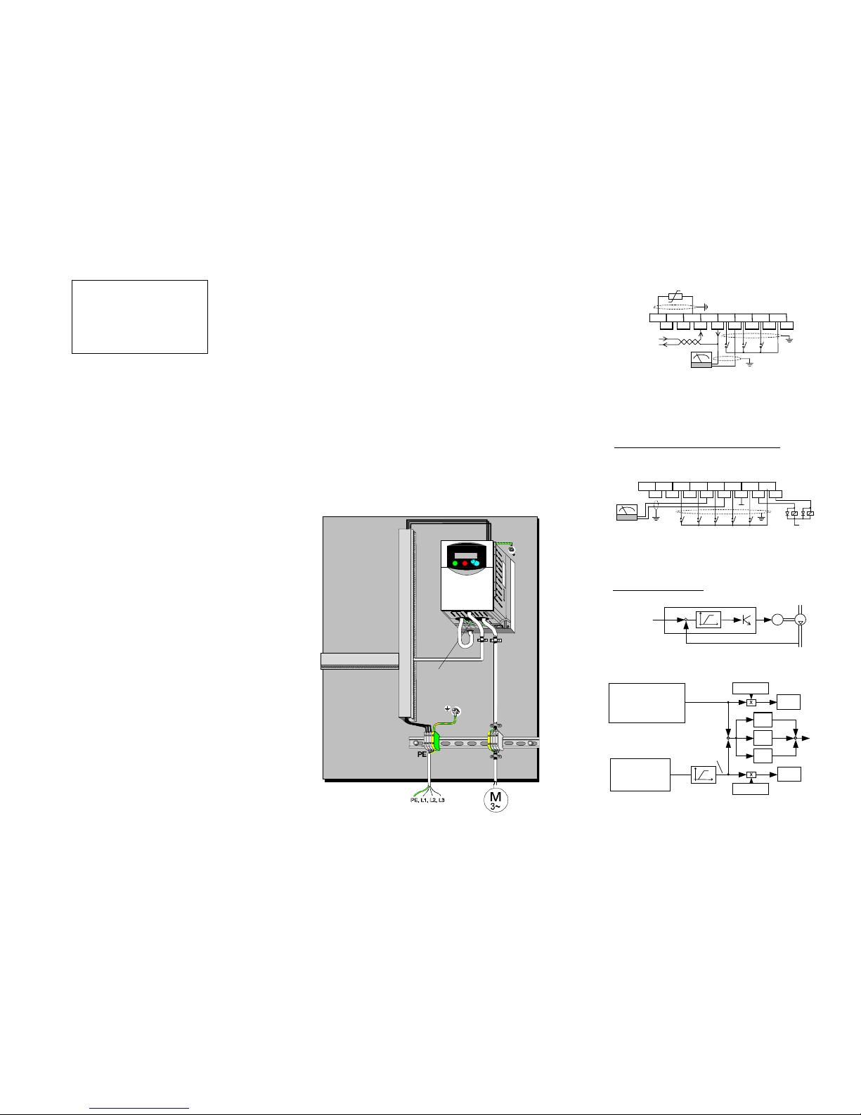
The inverter can now be started via input 1 (forward run) or input 2 (reverse run). If the
inputs RV and FW are both closed, the inverter is stopped. If input AT is configured as
normally open contact and is closed, current input on OI is used for set value
.
Wiring example: Set value 4..20mA and th er m istor
65
4321P24
HOOILFMCM21211
AT
24VDC
CF1
CF2
RUN
FA1
L
Reverse
Forward
Common for
in
p
ut si
g
nals
Frequency me t er
(
0..10V
,
1mA
)
Wiring example: Fixed set values; FA1 output and RUN output
Parameters for functions
A 01, A 02, F 02, F 03, C 01, C 02
, and
C 03
are set exactly the
same as in the example above. Additionally,
C 04
is set to 02 (CF1) and
C 05
is set to 03
(CF2). Fixed frequency set values are set via functions
A 21, A 22
, and
A 23
using parameters 0 to 360 (= frequency 0 to 360 Hz). The inverter can now be started via input 1 (FW) or
input 2 (RV). If the inputs RV and FW are both closed, the inverter is stopped. If none of the
digital inputs CF1 or CF2 is closed, frequency set value can be set using analog inputs O/OI.
P
A 72
0-300 l/h
= 0-100%)
I
A 73
D
A 74
+
+
+
F 01
+
Display
d 04
A 76 =
01
[PID current value at
terminals (O-L)]
0 – 10V = 0 – 500 l/h
A 01
= 01 (fixed set values)
A 21
= 100 l/h ( =33%)
A 22
= 200 l/h ( =66%)
A 23
= 300 l/h ( =100%)
A 75
= 3.00
A 75
= 3.00
Frequency set value
0-100% =50H z; limited to 10H z min.
0-6V-10V
Set value is give n i n fi xed interva ls: 100 , 20 0, 300l/h. T he cu rr ent value is in pu t by a senso r (0500l/h = 0-10V). When the difference is greater than 20% a warning is output. The frequency
must not fall below 10 Hz. The set value and current value are displayed as flow rate in l/h
(300l/h = 100% = 50 Hz maximum frequenc y).
In order to display the correct value,
A 75
is set to 3.00 so that a set value of 100% corresponds to a flow rate of 300l/h. In order to match the current value input (0-500l/h) to the set
value input (0-300l/h) the current value must be adjusted with parameters
A 11
to
A 14
, i.e.
A 14
must be set to 60% so that 300l/h pr ocess va lue corresponds to 100% current va lue.
Application example: Flow control
A flow contro l circuit is to be rea lized using the SJ10 0 inverte r bui lt i n PI D cont ro l.
0-300 l/h
= 0-6V
= 0-100%)
+
Flow rate
set value
Q
set
-
M
Flow rate current value Q
cur
f
cur
A 14 = 60%
set value adjustment
-
HITACHI IN V E RTER
SJ100 SERIES
QUICK REFERENCE GUIDE (Part 2/2)
Single phas e inpu t 200V clas s
Three phase i npu t 200V clas s
Three phase i npu t 400V clas s
CE-EMC Installation
This instruction describes the electromagnetically compatible setup o
f
your drive sys te m.
1. As an enduser you must ensure that the HF impedance between
frequency inverter, filter and ground is as small as possible.
•
See to it that the connections are metallic and have the largest
possible areas (zink-plated mounting plates)
2. Conductor loops act like antennas, especially when they encompass
large areas. Consequently:
•
Avoid unnecessary conductor loops
•
Avoid parallel arrangement of „clean“ and interference-prone
conductors
3. Lay the motor cable and all analog and digital contol lines shielded.
•
You should al lo w t he ef fective sh ie ld a re a o f th es e lines to remain as
large as possible; i.e., do not move the shield further away than
absolutely necessary.
•
With compact systems, if for example the frequency inverter is
communicating with the steering unit, in the same control cabinet
connected at the same PE-potential, the screen of control lines should
be put on, on both sides with PE. With branch systems, if for example
the communicating steering unit is not in the same control cabinet and
there is a distance between the systems, we recommend to put on the
screen of control lines only on the side of the frequency inverter. If it is
possible, direct in the cable entry section of the steering unit. The
screen of Motor cabels always must be put on, on both sides with PE.
•
The large area contact between shield and PE-potential you can
realise with a metal PG screw connection or a metallic mounting clip.
•
Use only copper mesh cable (CY) with 85% coverage
•
The shielding should not be interrupted at any point in the cable. If
the use of reactors , co nt ac to r s , te r min als or saf et y s w itches in the mot o r
output is necessary, the unshielded section should be kept as small as
possible.
•
Some motors have a rubber gasket between terminal box and motor
housing. Very often, the terminal boxes, and particularly the threads for
the metal PG screw connections, are painted. Make sure there is always
a good metallic connection between the shielding of the motor cable,
the metal PG screw connection, the terminal box and the motor
housing, and carefully remove this paint if necessary.
4. Very frequent l y , i nt erfere nce is coupled in thro ugh installa t i o n
cables . T hi s influence you c an minimi ze :
•
Lay interfering cables separately, a minimum of 0.25 m from cables
suscept ible to inte rferenc e.A part icular ly critica l point is laying ca bles
parallel o ver la rg er d ista nces . I f two cable s int ers ect , t he in ter fere nce is
smallest if they intersect at an angle of 90°. Cables susceptible to
interference should therefore only intersect motor cables, intermediate
circuit cables, or the wiring of a rheostat at right angles and never be
laid para lle l to them ove r larger d is ta nces.
5. The distance betwee n an i nte rference source a nd a n i nter ference
sink (interference-threatened device) essentially dete rmines the
effects of the emitted interference on the interference sink.
•
You should use only interference-free devices and maintain a
minimum distance of 0.25 m from the drive.
6. Safety measures
•
Ensure that the protective conductor terminal (PE) of the filter is
properly connected with the protective conductor terminal of the
frequency inverter. An HF ground connection via metal contact
between the housings of the filter and the frequency inverter, or solely
via cable shield, is not permitted as protective conductor connection.
The filter must be solidly and permanently connected with the ground
potential so as to preclude the danger of electric shock upon touching
the filter if a fault occurs. You can achieve this by:
- connecting it with a grounding conductor of at least 10 mm
2
;
- connecting a second grounding conductor, connected with a
separate grounding terminal, parallel to the protective conductor
(The cross section of each single protective conductor terminal
must be designed for the required nominal load)
HITACHI
55.0
RUN
STOP
RESET
MI MAX
RUN
PRG
Hz
A
POWER
2
STR
FUNC.
1
SJ1 0 0
WARNING
HAZARD OF PERSONAL INJURY OR
ELECTRIC SHOCK
Disconnect incoming power and wait
5 minutes b efore op ening f r o nt case.
PE connection
Figure: Hitachi fre quency inverter wit h fo ot print filte r
9 10 11
Page 6

NFENFENFENFENFENFEN
FE
LFR
LFR
Technical Specificat ion s
Inverter SJ100
-
(200V Series)
Protective structure (Note 1)IP20
Overvoltage category III
Maximum motor size (4P)
in kW (Note 2)
0.2 0.4
0.75 1.1 1.5 2.2
3.7 5.5 7.5
0.6 1.0 1.1 1.5 1. 9 3.1 4.3 6.9 9.1 12.2Maximum capacity
in kVA
0.6 1.0 1.2 1.6 2. 0 3.3 4.5 7.2 9.1 12.2
Input supply phase Single / Three phase Three phase
Rated input voltage 200VAC -10% ~ 240VA C +5% 50/60Hz +/-5%
Rated output voltage
(Note 3)
Three phase 20 0 ~ 240VAC
(Corresponds to input voltage)
Rated input current in A
Single phase (Three phase)
-
--
Rated output current in A
(Note 4a)
1.4 2.6 3.0 4.0 5. 0 8.0 11.0 17.5
32.0
Output frequency range 0.5 ~ 360 Hz (Note 5)
Frequency accuracy
(at 25°C +/-10°C)
Digital command: +/-0.01% of maximum frequency
Analog command: +/-0.1% of maximum frequency
Frequency setting resolution Digital setting: 0.1 Hz Analog setting: max. frequency / 1000
Voltage/frequency characterist. Constant, reduced or high starting (SLV) torque (Note 8)
Overload current capacity 150% during 60 seconds (once per 10 minutes)
Acceleration/deceleration time 0.1 ~ 3000 s in selecta b l e li n ea r a nd non- linear mode
(second acceleration/deceleration usable)
Starting torque (using SLV) > 200% > 180%
Dynam. braking, feedback
to capacitor (Note 6)2
approx. 100%
Exte rnal brakin g resistor approx. 150%
DC injection braking
braking time and braking force can be set)
Settings using keys or potentiometer
setting
External
signals
0-10VDC (input impedance 10k Ohm)
4-20mA (input impedance 250 Ohm)
Potentiometer 1k-2k Ohm, 1W (055 ~ 075LFU/LFR: 2W)
Via keys RUN (for start) and STOP/RESET (for stop)
(Default setting: forward run)
Forward /
Reverse ru n
Ext. signals Intelligent input terminals configurable as FW and RV
Intelligent input terminals
programmable as
FW: Forward run start/stop RV: Reverse run start/stop
CF1–CF4: Multistage speed JG: Jogging command
AT: Analog current input selection 2CH: 2.Accel./decel. time
FRS: Free run stop EXT: External trip
USP: USP function RS: Reset
SFT: Software lock PTC: Thermal protection
DB: Ext. DB input SET: 2. setting active
UP: Acceleration (Remote) DWN: Decelerat. (Remote)
Intelligent output terminals
programmable as
FA1/FA2: Frequency arrival sign al
OD: Deviation signal at PID control AL: Alarm signal
Frequency and current
monitoring
Connection of external analog meter (0-10VDC, max. 1mA) for
frequency or current; connection of external digital frequency meter
Fault alarm contact On when the inverter trips (1c contact).
Alternatively usable as intelligent output terminal
Other functions Autotuning, Automatic voltage regulation, retry; analog gain/vias
display, trip history monitoring , carrier frequency setting, PID
control, automatic torque boost, USP function, 2. Setting function,
ON/OFF control of cooling fan, and many mor e
Protection functions Overcurrent, overvoltage, undervoltage, electronic thermal, temp-
erature abnormality, ground fault, overload, CT error, BRD error
Ambient temperature -10 ~ 50°C (Note 7)
Storage temperature and
humidity
-25 ~ 70°C (dur in g short term tr a ns po rt at i o n pe r i od onl y )
20 ~ 90% RH (no dew condensation)
Vibration Max. 5.9m/s2 (=0.6g) at 10-55Hz
Installation location 1000m or less altitude indoors (IP54 or equivalent)
External color Grey
Options Remote operator, copy unit, cable for digital operator,
reactor for improving power factor, noise filter, OPE-J
Overall wei g ht (ap prox.) 0.7 0.8 1.3 2.3 2. 8 5.5 5.7
Braking
torque
Inputs
OutputsEnvironmental
HFE
HFE
HFE
HFE
HFE
HFE
Technical Specificat ion s
Inverter SJ100
-
(400V Series)
HFU
HFU
HFU
HFU
HFU
HFE
HFU
HFE
HFU
Protective structure (Note 1)IP20
Overvoltage category III
Maximum motor size (4P)
in kW (Note 2)
0.4 0.75 1.5 2.2 3.0 4.0 5.5 7.5
Maximum capacity
in kVA
1.1 1.9 2.9 4.2 6.2 6.6 9.9 12.2
Input supply phase Three Phase
Rated input voltage 380VAC -10% ~ 460VAC +10% 50/60H z +/-5%
Rated output voltage
(Note 3)
Three Phase 360 ~ 460VAC
(Corresponds to input voltage)
Rated input current in A 2.0 3.3 5.0 7.0 10.0 11.0 16.5 20.0
Rated output current in A
(Note 4b)
1.5 2.5 3.8 5.5 7.8 8.6 13.0 16.0
Output frequency range 0.5 ~ 360 Hz (Note 5)
Frequency accuracy
(at 25°C +/-10°C)
Digital command: +/-0.01% of maximum frequency
Analog command: +/-0.1% of maximum frequency
Frequency setting resolution Digital setting: 0.1 Hz
Analog setting: max. frequency / 1000
Voltage/frequency characterist. Constant, reduced or high starting (SLV) torque (Note 8)
Overload current capacity 150% during 60 seconds (once per 10 minutes)
Acceleration/deceleration time 0.1 ~ 3000 s in selecta b l e li n ea r a nd non- linear mode
(second acceleration/deceleration usable)
Starting torque (usi ng SLV) > 200% > 180%
Dynam. braking, feedback
to capacitor (Note 6)
approx. 100% approx.
70%
approx. 20% approx. 30%
Exte rnal brakin g resistor approx. 150% approx. 100% approx. 80%
DC injection braking
braking time and braking force can be set)
Settings using keys or potentiometer
setting
External
signals
0-10VDC (input impedance 10k Ohm)
4-20mA (input impedance 250 Ohm)
Potentiometer 1k-2k Ohm, 1W (055 ~ 075LFU/LFR: 2W)
Via keys RUN (for start) and STOP/RESET (for stop)
(Default setting: forward run)
Forward /
Reverse ru n
(S
tart/Sto
p)
Ext. signals Intelligent input terminals configurable as FW and RV
Intelligent input terminals
programmable as
FW: Forward run start/stop RV: Reverse run start/stop
CF1–CF4: Multistage speed JG: Jogging command
AT: Analog current input selection 2CH: 2.Accel. /decel. time
FRS: Free run stop EXT: External trip
USP: USP function RS: Reset
SFT: Software lock PTC: Thermal protection
DB: Ext. DB input SET: 2. setting active
UP: Acceleration (Remote) DWN: Decelerat. (Remote)
Intelligent output terminals
programmable as
FA1/FA2: Frequency arrival sign al
OD: Deviation signal at PID control AL: Alarm signal
Frequency and current
monitoring
Connection of external analog meter (0-10VDC, max. 1mA) for
Fault alarm contact On when the inverter trips (1c contact).
Alternatively usable as intelligent output terminal
Other functions Autotuning, Automatic voltage regulation, retry; analog gain/vias
display, trip history monitoring , carrier frequency setting, PID
control, automatic torque boost, USP function, 2. Setting function,
ON/OFF control of cooling fan, and many mor e
Protection functions Overcurrent, overvoltage, undervoltage, electronic thermal, temp-
erature abnormality, ground fault, overload, CT error, BRD error
Ambient temperature -10 ~ 50°C (Note 7)
Storage temperature and
humidity
-25 ~ 70°C (dur in g short term tr a ns po rt at i o n pe r i od onl y )
20 ~ 90% RH (no dew condensation)
Vibration Max. 5.9m/s2 (=0.6g) at 10-55Hz
Installation location 1000m or less altitude indoors (IP54 or equivalent)
External color Grey
Options Remote operator, copy unit, cable for digital operator,
reactor for improving power factor, noise filter, OPE-J
Overall wei g ht (ap prox.) 1.3 1.7 2.8 5. 5 5.7
Braking
torque
Inputs
OutputsEnvi r onmen tal
Legend:
A Control terminals B Alarm terminals
C Main terminals D Grounding t er mina l (All dimen sio ns are in mill imet e rs)
External di mensi ons and te r minal po si tions
67
80
4
110
120
10
5
L
7
2,5
DCBA
L
= 93 (002NF)
107 (004/005NF)
98 110 4
118
130
10
5
129
7
2,5
DCBA
98
110
4
118
130
5
156
7
6
DCBA
5
Air
Air
Fan
140
180
153
7
3,5
DCBA
128
168
10
5
SJ100-
002 NFE/NFU
004 NFE/NFU 005 NFE
SJ100-
004 HFE/HFU
007 NFE/NFU 011 NFE
SJ100-
007 HFE/HFU (without fan )
015 HFE/HFU
022 HFE/HFU
SJ100-
015 NFE/NFU
140
CBA
5
Air
Air
128
5
168
180
164 7
D
6
Fan
SJ100-
022 NFE/NFU 030 HFE
037 LFU 040 HFE/HFU
182
CBA
7
Air
Air
160
7
257
7
D
236
170
6
Second fan built in with
inverters 075LFU/LFR.
Fan
SJ100- 055 LFU/LFR
055 HFE/HFU/HFR
075 HFE/HFU/HFR
075 LFU/LFR
12 13 14
N
ote 1: Protective structure is based upon EN60529. Note 2: The applicab le motor is a H itachi
standard four-pole motor. When using another motor, make sure that the rated motor current does
not exceed the rated inverter cu rrent. Note 3: The output voltage will dec rease if input voltage
decreases. Note 4a: The in itial data setting values of 005N/011N are same as 004N/ 007N. So be sure
to set the values
b 12
and
b 22
of 004N/007N for each motor . (To be continued on next page)
(Contd. from prev . page) Note 4b: The initial data setting value of 030H is same as 040H. So be
sure to set the values
b 12
and
b 22
of 030H for the motor. Note 5: Confirm with the m oto r man u-
facturer the motors maximum rpm when using a motor running at frequencies higher than 50/60Hz.
N
ote 6: Torque will be reduced when the base frequency exceeds 50Hz. Note 7: In the range of 40
to 50°C reduce carri er frequency 2kHz and derate output current 80%, a nd remove the top cover.
 Loading...