

Hitachi SJ100-002NFU, SJ100-055LFU, SJ100-004-022NFU, SJ100-037LFU, SJ100-075LFU Supplemental Sheet
...
SJ100 Series Supplemental Sheet (NBM585XA-12)
ATTENTION
Note 1:
The revision level of the MFG No. distinguishes the following changes in Function Codes A81, C31
and C32
. The Inverter MGF No. is shown on the Specification Label (Nameplate), located on the right
side of the housing. The changes apply to inverters, which carry a revision code per the table below.
When you copy parameters between units manufactured before and after this change with a copy unit,
confirm Function Codes C31 and C32.
Example of MFG No. :
112H
T123451J001
Revision
A…K…1A…1K…2A…2H…
Revision Increment--------
Æ
Page
Changes
3-18
Inverter Models
Revision
before change
Applied
Revision
SJ100-002NFU 2E 2H
SJ100-004-022NFU 2G 2H
SJ100-037LFU 2E 2H
SJ100-055,075LFU K M
SJ100-004HFU 2F 2H
SJ100-007-040HFU 2G 2H
SJ100-055,075HFU L M
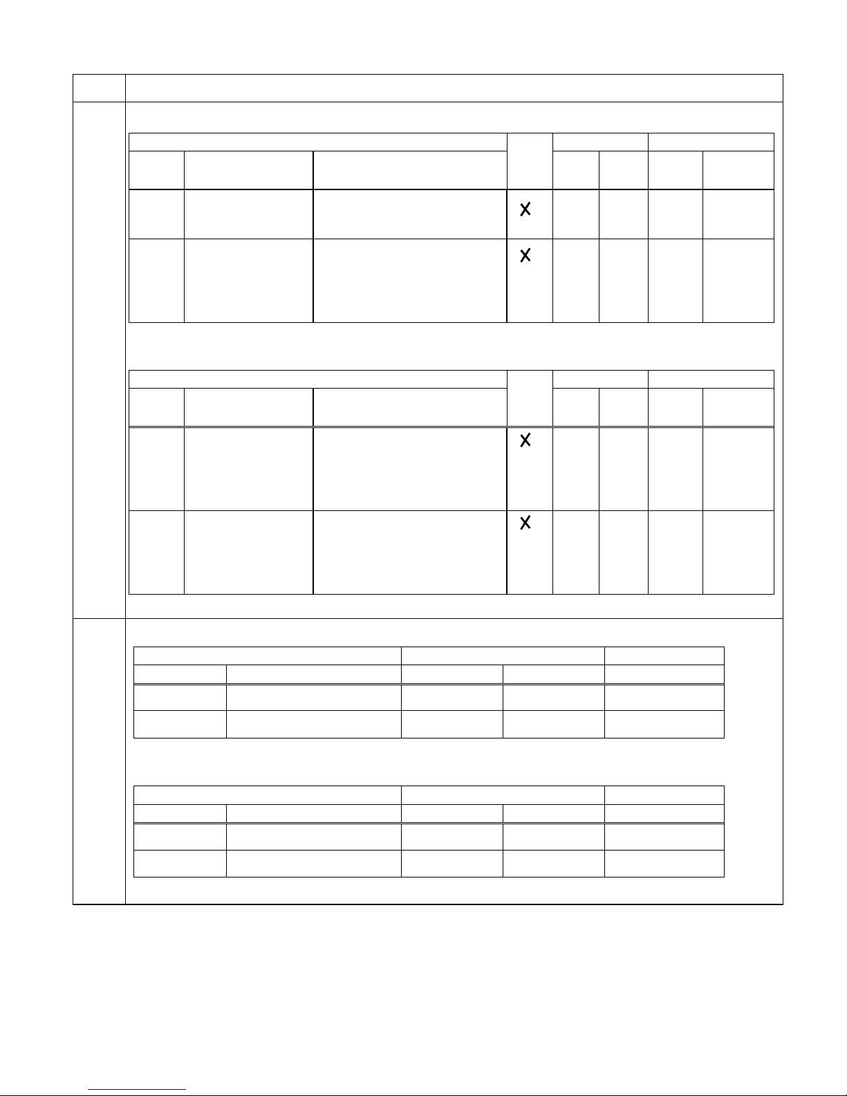
OLD DEFAULT SETTING:
“A” Function
Run-
Defaults DOP,DRW,DOP+
Func.
Code
Name Description
time
Edit
EU/
US
Units
Func.
Code
Name
A81 AVR function
select
Automatic (output) voltage
regulation, selects from three
types of AVR functions, three
option codes:
00…AVR enabled
01…AVR disabled
02…AVR enabled except
during deceleration
02
- F-03 AVR
MODE
NEW DEFAULT SETTING:
*Inverters manufactured after the revision as defined in Note 1 will have the following settings:
“A” Function
Run-
Defaults DOP,DRW,DOP+
Func.
Code
Name Description
time
Edit
EU/
US
Units
Func.
Code
Name
A81 AVR function
select
Automatic (output) voltage
regulation, selects from three
types of AVR functions, three
option codes:
00…AVR enabled
01…AVR disabled
02…AVR enabled except
during deceleration
00
- F-03 AVR
MODE
1/2
NBM585XA-12
Page
Changes
3-32
B-7
OLD DEFAULT SETTING:
“C” Function
Run-
Defaults DOP,DRW,DOP+
Func.
Code
Name Description
time
Edit
EU/
US
Units
Func.
Code
Name
C31 Reserved Factory use only; do not
change
00
- F-35 OUT-TM
O/C-1
C32 Terminal 11
active state
Select logic convention, two
option codes:
00…normally open [NO]
01…normally closed [NC]
00
- F-35 OUT-TM
O/C-2
NEW DEFAULT SETTING:
*Inverters manufactured after the revision as defined in Note 1 will have the following settings:
“C” Function
Run-
Defaults DOP,DRW,DOP+
Func.
Code
Name Description
time
Edit
EU/
US
Units
Func.
Code
Name
C31 Terminal 11
active state
Select logic convention, two
option codes:
00…normally open [NO]
01…normally closed [NC]
00
- F-35 OUT-TM
O/C-1
C32 Terminal 12
active state
Select logic convention, two
option codes:
00…normally open [NO]
01…normally closed [NC]
00
- F-35 OUT-TM
O/C-2
OLD DEFAULT SETTING:
“C” Group Parameters Default Setting User Setting
Func. Code Name -FE(Europe) -FU(USA)
C31 Factory-set - -
C32 Terminal 11 active state 00 00
NEW DEFAULT SETTING:
*Inverters manufactured after the revision as defined in Note 1 will have the following settings:
“C” Group Parameters Default Setting User Setting
Func. Code Name -FE(Europe) -FU(USA)
C31 Terminal 11 active state 00 00
C32 Terminal 12 active state 00 00
2/2
NBM585XA-12
 Loading...