

Page 1
Basic
HITACHI SJ Series
Guide
nverter
Read this “Basic
P1
”, and keep it handy for future reference.
If you have any
Refer to
ontact
for Inverter.
When making a contact, inform
the reference number on below.
Introduction
Chapter 1
:
Chapter 2
:
Chapter 4
:
Chapter 3
:
I/O Adjustment
Chapter 5
:
Chapter 6
:
Chapter 7
:
Index
inquiry or problem
Chapter 5 Troubleshooting
the Technical Inquiry Service
List of contact information
NT
Safety Instructions
Installation and Wiring
Settings
Operation Setting and Examples of
FAQ /
Troubleshooting
Maintenance and Inspection
Specifications
NT2511B
2511
I
Guide
Contents
,
or
C
to
X-1
Page 2

/Warranty & Contact us
Introduction Introduction/Cautions
Introduction
Thank you for purchasing Hitachi SJ Series P1 Inverter.
This is a user guide for basic handling and maintenance of
Hitachi SJ Series P1 Inverter.
For the purpose of reduction of paper usage and
provision of the latest information, we enclose the Basic
Guide only while providing the User's Guide for more
detailed description through electronic means instead of
CD or a printed document.
About the Basic Guide (this document)
The Basic Guide provides the minimum information
necessary for handling the product. Please make sure to
read this document as well as the User's Guide with more
detailed information.
About the User's Guide
The User's Guide provides detailed information necessary
for handling the product. Please make sure to read the
User's Guide for proper use.
If future updates make any difference from the Basic
Guide, the description in the User's Guide will have higher
priority. You should use the inverter by observing
specifications described in User's Guide. You should also
prevent risks by performing proper inspection and
maintenance.
Please refer to the following link for download:
Hitachi Industrial Equipment Systems' Website
http://www.hitachi-ies.co.jp/
Please follow as below on the Website.
Product Information -> Inverter -> Download of
technical data
Handling an optional products
If you use the inverter with optional products, also you
should read the instruction enclosed in those products.
Cautions
Proper use of the inverter
Please read the Basic Guide, User's Guide and optional
products instruction before handling. Read carefully the
Basic Guide, User's Guide or optional product instruction
before handling or performing maintenance of the
product.
Before attempting installation, operation, maintenance,
and inspection work, you should understand the
knowledge of equipment, information of safety,
precaution and how to use and service the inverter.
Cautions
No part of this document may be reproduced or reformed
in any form without the publisher's permission.
The contents of the document are subject to change
without prior notice.
If you lose the Basic Guide and need another one in
printed form, you will be charged for resupply, so please
keep it carefully.
You "CANNOT DO" what is not described in Basic Guide or
User's Guide. We are not responsible for any impact from
operations regardless of unexpected failure or accident
due to the operation or handling of the product in a
manner not specified in Basic Guide or User's Guide. We
apologize in advance for any inconvenience this may
cause.
If you find any unclear or incorrect description, missing
description, or misplaced or missing pages, please takes
time to inform Hitachi inverter technical service office.
Note that, the Basic Guide, User's Guide and the
instruction for each optional product enclosed, should be
delivered to the end user of the inverter. And also make
sure to be accessible any other guides or instruction to
the end user.
0-1
Page 3

/Warranty & Contact us
Introduction Introduction/Cautions
Method of Inquiry and Product Warranty
Method of Inquiry about Product
• For an inquiry about product damage or faults or a question
about the product, notify your supplier or Hitachi inverter
technical service office.
Product Warranty
• The product SJ series P1 inverter will be warranted by Hitachi
Industrial Equipment Systems Co., Ltd., afterward "Hitachi",
during the warranty period from your date of purchase only
under proper usage of product.
• Furthermore, the warranty expressed here is covered only for
the product delivered from Hitachi, and will not be
responsible for others damage or loss of products like a
motor or any equipment or systems damage caused by
improper usage of the product. Minimize the consequence
on equipment or system by applying safety design which is
able to notify a hazard alarm to the user in case of
malfunction or damage of the delivered product. The
selection and application of delivered product must be done
with sufficient margin on performance, as well as other
equipment or system with sufficient redundancy design. Also,
the compatibility of the product with the customer's
intended use is not warranted, hence the validation test
should be done by the customer by their responsibility
before put in operation.
• In case of delivery a defective product, or encountered a
defects on quality during a manufacturing process, Hitachi
will repair or exchange with free of charge, only when the
product is in warranty period (afterward, we call "warranty
service").
• The product will be warranted for one year from your date of
purchase. However, depending on case, sending technical
assistance for repairing will be charged to the customer. Also,
Hitachi will not be responsible of any readjustment or testing
on site.
• After warranty service, the exchanged or repaired part will be
warranted for 6 month from date of warranty service. Hitachi
will be responsible for repair or exchange of defective part
only for the exchanged or repaired part only during this
warranty period.
■ Inverter Model: It beginning with P1- in specification label.
■ Manufacturer Number(MFG No.): It shows in specification label.
■ Date of purchase: Customer's purchased period.
■ Inquiry contents:
・ Inform us the defective point and its condition.
・ Inform us the suspicious content and its detail.
• In order to receive warranty service, you should present the
recipe issued by product supplier or any other document that
permit to check the purchase date. However, any defects,
damage, malfunction or any other failure caused by one of
the following facts will not be covered by warranty service.
(1) Cannot confirm the purchase date.
(2) The damage or fault resulted from improper usage or
inadequate handling of the product and not conforming
usage described into the user's guide or basic guide.
(3) Incorrect usage of product, inadequate setting of
product and optional product, remodeling or inadequate
repair and repair carried out by unqualified repair
center.
(4) Deterioration and wear resulted from normal operation.
(5) Fault resulted from natural disaster, such as earthquake,
fire disaster, lightning strike, pollution, salt pollution, or
abnormal voltage or any others external factor.
(6) Shock, falling, or Vibration resulted during
transportation or displacement after purchase.
(7) Damage or fault resulted from remodeling firmware by
unqualified personal not belonging to Hitachi.
(8) Damage or fault resulted from customer's made
programing function (EzSQ).
(9) For overseas use.
• By warranty service, might lose the data stored inside the
product, as well as, customers made (EzSQ) program. Make
sure to back up by own responsibility. However, in case of
malfunction resulting from the circuit board of the storage
devices, the backup wil not be possible. It is recommended
to keep a backup during the testing phase by using VOP or PC
software ProDriveNext.
Liability Limitation
• Neither Hitachi-IES, Affiliated company nor related dealer are
liable to the written and unwritten public requirement
including the common sense of the product or requirement
in specific application
• Even more, Hitachi, affiliated company or related dealer are
not responsible of any incidental damage, special damage,
direct loss, or indirect loss (even predictable or not) resulted
on customer because of product defect.
0-2
Page 4

/Warranty & Contact us
Introduction Introduction/Cautions
Warranty Service
• The customer is able to receive a warranty service from
product supplier or service station, if the product does not
meet the function described on basic guide or user's guide.
Moreover, in case of any mismatch occurred between user's
guide and basic guide, user's guide content will take a
priority.
• Contact to your supplier or local Hitachi distributor or service
station for fare-paying services.
Change on Product Specification
• We are sorry because any information described in Brochure,
Basic Guide, User's Guide or Technical Document would be
modified without notice.
Precaution for Product Application
• The product should apply following the condition of use,
handling method and precautions described in User's Guide.
• The installed product should be confirmed previously by own
that the product installation has done as intended in the
customer system.
• When using Hitachi inverter consider on below
(1) Select inverter with sufficient capacity for rate current
and performance.
(2) Safety design, for example, redundant system design.
(3) Equipment design where minimize hazard in case of
inverter failure.
(4) For safety precautions, make a system configuration that
alarms the hazard to user.
(5) Periodic maintenance of Hitachi inverter and customer's
equipment.
• Hitachi inverter is designed and manufactured intentionally
to be applied for general industrial equipment application.
It is not intended to be used for the applications listed
below therefore. In case inverter is used for these
applications, it is out of warranty unless there is a special
written agreement. Otherwise, the product will not be
warranted.
(1) Special application such as aircraft, spacecraft, nuclear,
electric power, passenger transportation, medical,
submarine repeater, etc.
(2) For application such as elevator, amusement equipment,
medical equipment which might have a big effect on
human life and property.
• Even for above application, in case there is an agreement for
the limitation of the purpose and quality, please contact to
our sales office. Further study will be carried out to check
whether inverter is applicable for that specific application or
not.
• For applications that involve human life, or have risk of
important loss, make sure to avoid a critical accident by
installing a fail-safe device, protecting device, detecting
device, alarm device, or spare device, etc.
• This inverter is only for three phase induction motor [IM] or
three phase synchronous motor [SM(SMM)].
• For any other application make inquiries.
Supplement
• Refer to "Chapter 7 Specification" for short lifespan
component.
• For optional product refer attached instruction.
• This warranty term will not restrict a legal right of customer
who has purchased the product.
• Contact to the local supplier for warranty of purchased
product sales in oversea.
Contact Information
Hitachi America, Ltd. (Charlotte Office)
Industrial Components and Equipment Division
6901 Northpark Blvd., Suite A, Charlotte, NC 28216,
U.S.A
TEL : +1(704) 494-3008
FAX : +1(704) 599-4108
Hitachi Europe GmbH
Industrial Components & Equipment Group
Am Seestern 18 (Euro Center),
D-40547 Dusseldorf,
Germany
TEL : +49-211-5283-0
FAX : +49-211-5283-649
Hitachi Asia Ltd.
Industrial Components & Equipment Division
No.30 Pioneer Crescent, #10-15 West Park Bizcentral,
Singapore 628560,
Singapore
TEL : +65-6305-7400
FAX : +65-6305-7401
Hitachi Australia Ltd.
Level 3, 82 Waterloo Road
North Ryde, N.S.W.2113
Australia
TEL : +61-2-9888-4100
FAX : +61-2-9888-4188
Hitachi Industrial Equipment Systems Co., Ltd.
AKS Building, 3, Kanda
Nereibei-cho, Chiyoda-ku,
Tokyo, 101-0022
Japan
TEL : +81-3-4345-6910
FAX : +81-3-4345-6067
0-3
Page 5

●
●
●
●
Contents
Quick start
Introduction/instructions
Types of Warnings
Description of Safety Symbols
Precautions for Installation
Precautions
Precautions
Check the Inverter
Install the Inverter
Dimensions Drawing
Inverter Wiring
Wiring of
Recommended
Operation Setting and Examples of IO Adjustment
overview
Troubleshooting
Cautions for Maintenance/Inspection
Daily and Periodic Inspections
Method of Checking the Inverter and Converter
................................
Specifications Table
Appendix Index
Quick start
Chapter 1 Safety
Chapter 2 Installation and Wiring
Chapter 3 Operation Setting and
Chapter 4 Settings
Chapter 5 Troubleshooting
Chapter 7 Specifications
Chapter 6
................................
................................
for Wiring
and Test Running
................................
................................
................................
................................
the main circuit
wire gauges, accessories etc.
................................
................................
................................
................................
................................
................................
Instructions
Inspection and
..............................
................................
..............................
................................
................................
................................
..............................
................................
.................
Maintenance
.......
................
.
........
.................
................
................
.............
.....................
.....
.......
..................
4
....................
..................
..
..............
index
Appendix
Examples of IO Adjustment
Precautions
Precautions for
Other Cautions
Compliance
Compliance
Applicable Circuit Breaker
opper Breaking Resistor
Wiring
Wiring of the Control Circuit
Control Circuit Wiring Section
Residual Risk
Parameters
-
Output of Life Warning
Methods of Measuring the Input/Output Voltages,
Current, and Power
Method of Inquiry and Product Warranty
................................
for Maintenance/Inspection
Dispolsal
................................
to European Directive (CE)
to UL standards
................................
................................
naming
Bus Capacitor Life
................................
................................
................................
................................
................................
................................
................................
................................
................................
................................
................................
...............................
.................
............................
......................
.............................
...................
.....................
Contents
to Run
0-1
0-2
1-1
1-1
1-2
1-2
1-3
2-1
2-2
2-4
2-6
2-7
2-8
●
●
Ch
Contents
.......... 0-3
0-4
......... 2-10
1-4
.......... 1-4
1-4
1-5
....... 1-7
........ 2-12
....... 2-13
..... 2-17
... 2-19
2-24
Keypad
Monitor
Circuits
naming
3-1
..................
4-1
-10
5-1
6-1
6-2
6-4
DC
Curve
4-13
........ 6-5
............... 6-5
6-6
...........
7-1
-1
-1
0-4
Page 6

Contents
Contents
(Memo)
0-5
Page 7
Chapter 1
1.1
In the Basic Manual, the severity levels of
precautions and residual risks are classified as:
"
Display
Even more, that "
to a serious risk depend on the circumstances. Be sure to
follow the instruction because whichever contains
important safety description.
Chapter 1
Safety Instructions
Types of Warnings
and
eanings
Indicates that incorrect handling may cause hazardous
situations, which would most likely result in serious
injury or death,
loss or damage.
Indicates that incorrect
situations, which may result in serious personal injury or
death, and may result in major
Indicates that incorrect handling may cause hazardous
which may result in moderate or slig
injury or damage, and may result
loss or damage.
CAUTION
and may result in major physical
WARNING
handling may cause hazardous
CAUTION
CAUTION
DANGER
physical loss or damage.
" level description may lead
DANGER
physical
1.2
It describes annotation of t
to follow and pay attention of content.
Symbols
1.3 Description of Safety Symbols
Read carefully following safety instruction for handling.
Description of Safety Symbols
eaning
Indicates a danger, warning or caution notice
fire, electric shock and high temperature
while handling the product
Details are indicated in or near
or words.
Indicates “what you must not do”
the described acts
product.
Indicates “what you must do”
the instructions
product.
Safety Instructions
s
The
drawing on the left indicates
specific and general
The drawing on the left indicates
damage
in the operation of the
ymbols in context
due to electric
operation of the
according to
. Be sure
“a
“a
to prohibit
WARNING"
m
personal
safety
"
"
".
",
m
for
noncaution”.
possible
shock”.
he
s
.
in the
by pictures
danger or
situations,
personal
only
ht
1-1
Page 8

Chapter 1
1.3.1
Caution
Precautions for installation
●
recautions for Wiring
●
●
Incorrect handling may result in personal
or severe injury, or may result in damage to
inverter, motor or the whole system.
Be sure to read this Basic Manual and
documents thoroughly
operating, maintaining, inspecting or
You run the risk of fire!
Do not place flammable materials near
installed inverter.
Prevent foreign matter (e.g., cut pieces of wire,
sputtering welding materials, iron chips, wire,
and dust) from
Install the inverter on a non
Install the inverter in a well
not exposed to direct sunlight.
where the inverter is exposed to high
high humidity, condensation, dust,
explosive gases,
rinding fluid mist,
You run the risk of injury!
Do not install and operate the inverter
damaged or its parts are missing.
You run the risk of electric shock or
Be sure to ground
Commit wiring work to
Before wiring, make sure that the power supply
run the risk of failure of the
Do not pull the wire after wiring.
before installing, wiring,
penetrating into
-
corrosive gases, flammable
or salt water.
the inverter.
a qualified electrician.
death
appended
using the
to
the inverter.
flammable surface,
ventilated indoor
Avoid places
if it is
WARNING
D
DANGER
Failure
Prohibited
GER
Caution
Fall
Injury
Prohibited
Practice
Electric
shock
Injury
Short
circuit
Ground
Prohibited
Practice
Practice
Many of the drawings
inverter with covers and/or parts
as removed to
Do not operate the inverter in the status shown in
those drawings. If you have removed the
and/or parts, be sure to reinstall them in their
original positions before starting operation,
follow all instructions when operating the inverter.
You run the risk of injury due to the
inverter falling
Do not hold its cover parts w
inverter.
Install the inverter on a structure able to bear
the weight specified in this Basic
Install the inverter on a vertical wall that is free
of vibrations.
You run the risk of failure of the inverter!
The inverter is precision equipment.
allow it to fall or be subject to high impacts.
Also do not step on it, or place a heavy load on
You run the risk of electric shock and
injury!
Perform wiring
You run the risk of short circuit and ground
fault!
Do not remove rubber bushings from the wiring
section.
may damage the wire.
Safety Instructions
illustrate the details.
only after installing the inverter.
Otherwise, the edges of the wiring cover
in the Basic
blocking your view
hen carrying the
the
covers
and
Do not
Caution
Practice
1.3.2
Fire
Prohibited
Practice
Injury
Prohibited
•
•
inverter.
●
•
•
•
such as, metal
•
site
temperature,
gases, g
•
the
•
Guide show
•
●
•
•
•
Guide.
●
•
•
it.
surface.
the
-
1.3.3 P
Electric
shock Fire
Practice
Failure
Prohibited
AN
fire!
•
•
•
is off.
You
inverter!
•
●
•
●
•
1-2
Page 9

Chapter 1
●
●
recautions
●
●
●
Injury
You run the risk of injury or fire!
Do not connect AC power supply to
output terminals (U, V, and W)
Make sure that the voltage of AC power supply
matches the rated voltage of your inverter.
You run the risk of electric shock
and injury!
Before operating slide switch SW in the
inverter, be sure to turn off the power supply.
Since the inverter supports two modes of
fan operation, the inverter power is
not always off, even when the cooling fan is
Therefore, be su
the power supply is off before wiring.
Run and
You run the risk of electric shock or
While power is supplied to the
touch any internal part or terminal of the
inverter. Also do not check signals, or connect
or disconnect any wire or connector.
While power is supplied to the inverter, do not
touch any internal part of the in
m
You run the risk of electric shock!
Be sure to close the terminal block cover
before turning on the inverter power.
open the terminal block cover
being supplied to the inverter or
remains inside.
Do not operate switches
You run the risk of injury or fire!
While power is supplied to the inverter,
terminal of the inverter,
has stopped.
Test Running
aterial such as a rod
with wet hands.
any of the
re to confirm that
inverter, do not
verter. Also do
and etc.
Do not
while power is
voltage
do not
even if it
WARNING
DANGER
Prohibited
Injury
Damage
Prohibited
Injury
Prohibited
Practice
Practice
Do not use a single
Do not connect a resistor directly to any of the
DC terminals (PD, P, and N).
Do not use
the primary and secondary sides of the inverter
to stop its operation.
Tighten each screw to the specified torque.
No screws must be left loose.
Connect an earth
input circuit.
Use only the power cables, earth
breaker, and magnetic contactors that have
specified capacity (ratings).
not select the retry mode for controlling an
elevating or traveling device because free
status occurs in retry mode.
If the retry mode has been selected, the inverter
will restart suddenly after a break in the tripping
status.
the inverter when the inverter is under such
circumstances.
safety can be ensured,
restarts sudden
The [STOP] key on the operator keypad is effective
only when its function is enabled by setting.
Prepare an emergency
If an operation command has been input to
inverter
inverter may
recovery.
danger,
inverter
If an operation command has been input to the
inverter before the inverter enters alarm status,
the inverter will restart suddenly when the alarm
status is reset.
make sure that no operation command
input.
Safety Instructions
You run the risk of fire!
the magnetic contactor installed on
-
You run the risk of injury and damage to
You run the risk of injury!
Stay away from the machine controlled by
(Design the machine so that human
before a short
restart operation after the power
If such a restart may put persons in
design a control circuit that disables the
rom restarting after power recovery.
Before resetting the alarm status,
leakage breaker
even when the inverter
stop switch separately.
power failure, the
wer
leakage
the
running
the
has been
Fire
Prohibited
Practice
Electric
shock
Injury
Practice
1.3.4 P
Electric
shock
Fire
Prohibited
Electric
shock
Prohibited
Injury
Fire
•
•
•
•
cooling-
stopped.
fire!
•
•
not insert a
•
•
•
touch the
to
.
Fire
●
•
•
•
•
•
•
•
-phase input.
-
to the po
-
●
.
• Do
•
•
•
•
machine.
●
-
ly.)
-term
Prohibited
1-3
Page 10
Chapter 1
●
Precautions for
●
Precautions for disposal
●
ther Cautions
●
•
You run the
The inverter
operating
capacity and ratings
before operating
When you run the motor at a high frequency,
and confirm to each manufactures of a
permitting revolution of
and machine
rotate
and vibrations
Maintenance/Inspection
You run the risk of electric shock!
Before inspecting the inverter, be sure to turn
off the power supply and
(Before inspection, confirm
Charge lamp
voltage between terminals P and N is
You run the risk of injury and
explosion!
For disposal of the inverter, outsource to a
industrial waste disposal contractor.
Disposing of the inverter on your own may
result in an explosion of the capacitor or
produce poisonous gas.
Contact us or your distributor
You run the risk of electric shock, fire
and injury!
Never modify the inverter.
DANGER
risk of injury and damage to
allows you to
motor.
of the motor or machine
the
direction
while operating
wait for 10 minutes
on the inverter is off and
ontrol the
onfirm the
motor
, abnormal
that the
the DC
45 V or
for fixing the
WARNING
DANGER
DANGER
Burn
njury
Prohibited
Injury
Practice
Prohibited
Practice
Life cycle
Practice
You run the risk of burn injury.
Inverter heat sink will heat up during operation.
Do not touch the heat sink
You run the risk of injury!
Install an external brake system
Commit only a designated person to
maintenance,
of parts.
metal accessories, e.g., bracelets,
maintenance and inspection work and to use
insulated tools
A qualified waste disposer includes
industr
ind
the
the
leansing
You run the risk of
the
Sterilizing and disinfecting a packaging
materials
fumigation method.
the fumigation treatment,
receive a critical damage
steams
(including fluorine, chlorine, bromine and
iodine)
Safety Instructions
inspection, and the replacement
(Be sure to remove wristwatches and
for the
ial waste collector/transporter
ustrial waste disposal operator
act related to
m
disposing of the inverter.
a
use a means other than
Especially,
can cause corrosion in
CAUTION
if needed.
procedures stipulated in
anagement and
significantly
If the product is included in
electronic parts
from emitted gases or
halogen disinfectants
the capacitor.
before
and
. Follow
ublic
shortening
wood
wood
Injury
Damage
Practice
1.3.5
Electric
shock
Practice
1.3.6
Injury
Explosion
Practice
1.3.7 O
Electric
shock
Fire
Injury
Prohibited
•
•
• Check the
•
•
•
machine.
speed of
check
sound,
or more.
less.)
qualified
inverter.
●
easily
c
I
C
.
respective
.
motor
.
•
.
●
•
•
work.)
•
waste
c
for
p
●
•
life cycle of
.
product!
1-4
Page 11

1.4
(CE)
Compatibility)
The SJ series P1 inverter conforms to requirements of
Electromagnetic Compatibility (EMC) Directive (2014/30/EU).
However, when using the
with the following specifications and requirements to meet the
EMC Directive and other standards in Europe:
1. Power supply requirements
2. Installation requirement
3. Wiring requirements
4. Environmental requirements
Chapter 1
Compliance
Caution for EMC (Electromagnetic
WARNING: This equipment must be installed, adjusted,
and maintained by qualified engineers who have expert
wledge of electric work, inverter operation, and the
hazardous circumstances that can occur. Otherwise,
personal injury may result.
a. Voltage fluctuation must be
b. Voltage imbalance must be ±3% or less.
c. Frequency variation must be ±4% or less.
d. Total harmonic distortion (THD) of voltage must be ±10% or
a. SJ series P1 includes a built
filter must be activated.
According to EN61800
any inverter with only C3 filter inside may NOT be
connected to a low voltage public power supply in
residential areas since for these installations C1 is required.
In case of external filter
required according to EN61800
high frequency interference in residential areas which
may require additional EMC measures”.
d. According to the EN6100
DC choke should
a. A shielded wire (screened cable) must be used for motor
wiring, and the length of the cable must be according to the
following table (Table 1 on page 1
b. The carrier frequ
following table to meet an EMC requirement (Table1 on
c. The main circuit wiring must be separated from the control
circuit wiring.
EMC
a. SJ series P1
must be according to SJ series P1 specifications.
to European Directive
inverter in Europe, you must comply
3 it is mandatory to mention that
for
3
be installed
ency must be set according to the
filter is used)
inverter that is activated built
15% to +10% or less.
in EMC filter. The built
C2, an additional note is
3 that “this product may
3
additional
for reducing harmonics in
in EMC
AC reactor or
Safety Instructions
1.4.1
less.
b.
kno
-
-
-
-
c.
emit
power line.
page 1-12).
(When an
-
-
-12, an
-12).
-in EMC filter
1-5
Page 12

Cable
Carrier
Cable
Carrier
Chapter 1
Table 1
Safety Instructions
Model Cat.
Length
(m)
P1-00044-L
(P1-004L)
P1-00080-L
(P1-007L)
P1-00104-L
(P1-015L)
P1-00156-L
(P1-022L)
P1-00228-L
(P1-037L)
P1-00330-L
(P1-055L)
P1-00460-L
(P1-075L)
P1-00600-L
(P1-110L)
P1-00800-L
(P1-150L)
P1-00930-L
(P1-185L)
P1-01240-L
(P1-220L)
P1-01530-L
(P1-300L)
P1-01850-L
(P1-370L)
P1-02290-L
(P1-450L)
P1-02950-L
(P1-550L)
- - - -
- - - -
- - - -
- - - -
C3 10 2 - - - -
C3 10 2
C3 10 2
C3 10 2
C3 10 2
C3 5 2
C3 5 2
C3 5 2
C3 10 1
C3 10 1
C3 10 1
C3 5 2
C3 5 2
C3 5 2
C3 5 2
Frequency
(kHz)
Model Cat.
P1-00041-H
(P1-007H)
P1-00054-H
(P1-015H)
P1-00083-H
(P1-022H)
P1-00126-H
(P1-037H)
P1-00175-H
(P1-055H)
P1-00250-H
(P1-075H)
P1-00310-H
(P1-110H)
P1-00400-H
(P1-150H)
P1-00470-H
(P1-185H)
P1-00620-H
(P1-220H)
P1-00770-H
(P1-300H)
P1-00930-H
(P1-370H)
P1-01160-H
(P1-450H)
P1-01470-H
(P1-550H)
P1-01760-H
(P1-750H)
P1-02130-H
(P1-900H)
P1-02520-H
(P1-1100H)
P1-03160-H
(P1-1320H)
Length
(m)
C3 10 2
C3 10 2
C3 10 2
C3 10 2
C3 5 2
C3 5 2
C3 5 2
C3 10 2
C3 10 2
C3 10 2
C3 5 2
C3 5 2
C3 5 2
C3 5 2
C3 5 2
C3 5 2
C3 5 2
C3 5 2
Frequency
(kHz)
1-6
Page 13

Chapter 1
Safety Instructions
1.5 Compliance to UL standards
1.5.1 UL CAUTION
GENERAL:
SJ series Type P1 inverter is open type AC Inverter with
three phase input and three phase output. It is intended
to be used in an enclosure. It is used to provide both an
adjustable voltage and adjustable frequency to the AC
motor. SJ-P1 automatically maintains the required
volts-Hz ratio as a function to control motor speed. It is
multi-rated device and the ratings are selectable
according to load types by operator with key pad
operation.
Markings:
Maximum Surrounding Temperature:
- ND (Normal Duty): 50degC
- LD (Low Duty): 45degC
- VLD (Very Low Duty): 40degC
Storage Environment rating:
- 65degC (for transportation)
Instruction for installation:
- Pollution degree 2 environment and Overvoltage
category III
Electrical Connections:
- See “7.5 Main circuit terminal wiring” of user's
guide
Interconnection and wiring diagrams:
- See “7.7 Control circuit terminal wiring” of user's
guide
Short circuit rating and overcurrent protection device
rating:
P1-L series models
- Suitable for use on a circuit capable of delivering not
more than 5,000 rms symmetrical amperes, 240 V
maximum”.
P1-H series models
- Suitable for use on a circuit capable of delivering not
more than 5,000 rms symmetrical amperes, 500 V
maximum”.
Integral:
- Integral solid state short circuit protection does not
provide branch circuit protection. Branch circuit
protection must be provided in accordance with the
National Electrical Code and any additional local
codes
1-7
Page 14

VLD
LD
ND
VLD
VLD
LD LD
ND ND
VLD
VLD
LD LD
ND ND
VLD
VLD
LD LD
ND ND
VLD
VLD
12
LD LD
ND ND
VLD
VLD
3 10
LD LD
ND ND
VLD
3 6
VLD
3 8
LD
8 LD
ND ND
VLD
VLD
LD LD
ND 6 ND
VLD
VLD
LD LD
ND 4 ND
VLD
1
VLD
LD 2 LD
ND 3 ND 8
VLD
2/0
VLD
LD 1/0 LD
ND 1 ND 6
VLD
VLD
1
LD LD 2
ND ND 3
VLD
VLD
LD
LD
ND 4/0 ND
VLD
VLD
LD
LD
ND
ND 1
VLD
VLD
LD
LD
ND 350kcmil
ND
2/0
Chapter 1
Safety Instructions
Terminal size and terminal tightening torque for field
wiring:
Model Load Type
P1-00044-L
(P1-004L)
P1-00080-L
(P1-007L)
P1-00104-L
(P1-015L)
P1-00156-L
(P1-022L)
P1-00228-L
(P1-037L)
P1-00330-L
(P1-055L)
P1-00460-L
(P1-075L)
Required
Torque
(N.m)
1.4 14
1.4 14
1.4 14
1.4 10
1.4 10
3 8
Conductor
size
(AWG)
Model Load Type
P1-00041-H
(P1-007H)
P1-00054-H
(P1-015H)
P1-00083-H
(P1-022H)
P1-00126-H
(P1-037H)
P1-00175-H
(P1-055H)
P1-00250-H
(P1-075H)
Required
Torque
(N.m)
1.4 14
1.4 14
1.4 14
1.4
Conductor
size
(AWG)
14
12
10
P1-00600-L
(P1-110L)
P1-00800-L
(P1-150L)
P1-00930-L
(P1-185L)
P1-01240-L
(P1-220L)
P1-01530-L
(P1-300L)
P1-01850-L
(P1-370L)
P1-02290-L
(P1-450L)
P1-02950-L
(P1-550L)
4
2.5 – 3.0
2.5 – 3.0
5.5 – 6.6
6.0
15.0
6.0 – 10.0
19.6
Parallel of 1/0
Parallel of 1/0
Parallel of 1/0
Parallel of 2/0
Parallel of 1/0
Parallel of 1/0
Parallel of 3/0
Parallel of 3/0
- Use 75degC only for temperature rating of field
wiring.
- Use Cupper conductors only.
4
3
P1-00310-H
(P1-110H)
P1-00400-H
(P1-150H)
P1-00470-H
(P1-185H)
P1-00620-H
(P1-220H)
P1-00770-H
(P1-300H)
P1-00930-H
(P1-370H)
P1-01160-H
(P1-450H)
P1-01470-H
(P1-550H)
4 8
4 8
4
4
6.0
15.0 1
Parallel of 2/0
6.0 – 10.0
6.0 – 10.0
Parallel of 1/0
Parallel of 1/0
Parallel of 1/0
6
4
1-8
Page 15

Chapter 1
Safety Instructions
Required protection by Fuse and circuit-breakers:
P1-L series models
Model
P1-00044-L
(P1-004L)
P1-00080-L
(P1-007L)
P1-00104-L
(P1-015L)
P1-00156-L
(P1-022L)
P1-00228-L
(P1-037L)
P1-00330-L
(P1-055L)
P1-00460-L
(P1-075L)
P1-00600-L
(P1-110L)
P1-00800-L
(P1-150L)
P1-00930-L
(P1-185L)
P1-01240-L
(P1-220L)
P1-01530-L
(P1-300L)
P1-01850-L
(P1-370L)
P1-02290-L
(P1-450L)
P1-02950-L
(P1-550L)
Type
Class J or T 600 50 - -
Class J or T 600 50 - -
Class J or T 600 50 - -
Class J or T 600 50 - -
Class J or T 600 50 - -
Class J or T 600 100 - -
Class J or T 600 150 - -
Class J or T 600 150 - -
Class J or T 600 150 - -
Class J or T 600 200 - -
Class J or T 600 200 - -
Class J or T 600 300 - -
Class J or T 600 300
Class J or T 600 300
Class J or T 600 350
Voltage (V) Current (A) Voltage (V) Current (A)
Fuse Circuit Breaker
Maximum Rating Maximum Rating
- -
- -
- -
1-9
Page 16

Chapter 1
Safety Instructions
P1-H series models
Model
P1-00041-H
(P1-007H)
P1-00054-H
(P1-015H)
P1-00083-H
(P1-022H)
P1-00126-H
(P1-037H)
P1-00175-H
(P1-055H)
P1-00250-H
(P1-075H)
P1-00310-H
(P1-110H)
P1-00400-H
(P1-150H)
P1-00470-H
(P1-185H)
P1-00620-H
(P1-220H)
P1-00770-H
(P1-300H)
P1-00930-H
(P1-370H)
P1-01160-H
(P1-450H)
P1-01470-H
(P1-550H)
(Memo)
Fuse Circuit Breaker
Type
Class J or T 600 30 - -
Class J or T 600 30 - -
Class J or T 600 30 - -
Class J or T 600 30 - -
Class J or T 600 75 - -
Class J or T 600 75 - -
Class J or T 600 75 - -
Class J or T 600 100 - -
Class J or T 600 100 - -
Class J or T 600 100 - -
Class J or T 600 200 - -
Class J or T 600 200 - -
Class J or T 600 200 - -
Class J or T 600 250 - -
Voltage (V) Current (A) Voltage (V) Current (A)
Maximum Rating Maximum Rating
1-10
Page 17

MADE IN JAPAN
INVERTER
NE18361
-
***
MFG No. 62AA****** BB001
SJ series type P1
-
Basic
Guide
Eye bolts for hanging the inverter
Heat sink
M3×8
screw
4pcs
Chapter 2
Chapter 2
Installation and Wiring
2.1 Check the Inverter
Check the contents in the package, and confirm the
inverter model with a specification label.
The model of the product is as follows:
E.g.: 200V class input voltage for Japan
(1) Series name P1
(2) Motor maximum rated current (at VLD rated current
(3) Input power specification
(4) Panel
(5) Region (None): Japan;
(6) Integrated noise filter
•
Specification label example
Description example for P1-00228-LFF
(*) means eigenvalues
Inverter
Applicable motor capacity for ND rating is 3.7kW
ND rated current 17.5A
LD rated current 19.6A
VLD rated current 22.8A
P1
(1) (2) (3) (4) (5) (6)
00001: 0.1A to 99999: 9999.9A
L: three-phase 200V class;
H: three-phase 400V class
B: no operator keypad equipped;
F: panel equipped
E: Europe/Southeast Asia;
U: North America;
C: China
In case of (None), blank field is omitted.
F: integrated noise filter equipped;
CB: conduit box equipped
When both F and CB are equipped, it is indicated as
00228
FCB.
-
(This document)
L F
Configuration and description contents vary
depending on the model.
Refer to User's Guide for more details.
If the inverter is shipped incorporated with optional
products, optional instruction will be enclosed.
Spacer 4 pcs
P1-01240-L(P1-220L)
P1-00228-LFF example illustration in below.
Optional slots
F
Wire separation plate
Refer to each optional product
instruction for detail.
Backing plate
Operator keypad
USB (Micro-B)
Control circuit
terminal block
Terminal block
cover
Installation and Wiring
P1-01850L/-00930H or above
(enclosed in the package)
Main circuit
terminals
Specification label
Inverter model
Input ratings
(Frequency/voltage/No. of
phases/Current)
Output ratings
(Frequency/voltage/No. of
phases/Rate current)
MFG No.; factory serial No.
Ver.2.00
Model: P1-00228-LFF
Input/Entrée:50Hz,60Hz 200–240V 3ph 27.1/23.3/20.8A
Output/Sortie:0-590Hz 200–240V 3ph 22.8/19.6/17.5A
Date:****
Hitachi Industrial Equipment
Systems Co., Ltd.
2-1
Page 18

2.2 Install the Inverter
Chapter 2
ransportation
The inverter
carrying the inverter, handle it carefully to prevent
damage to the parts.
Do not carry the inverter by holding the front or
terminal block cover. Doing so may cause the
inverter to fall.
Do not install and operate the inverter if it is
damaged or its parts are missing.
mbient temperature
Avoid installing the inverter in a place where the
ambient temperature goes above or
allowable range defined by the standard inverter
specification.
Ambient temperature:
ND rated
LD rated
VLD rated
Measure the temperature in a position about 5 cm
distant from the bottom
inverter, and check that the measured
temperature
Operating the inverter at a temperature outside
this range will shorten the invert
the capacitor life), resulting in damage to the
inverter.
Do not install
umidity
Avoid installing the inverter in a place where the
relative humidity goes above or below the ran
(20% to 90% RH), as defined by the standard
inverter specification. Avoid a place where the
inverter is subject to condensation.
Condensation inside the inverter will result in
short circuits, which may c
inverter.
exposed to direct sunlight.
is made of plastics
10 to 50°C
10 to 45°C
10 to 40°C
ent space around the inverter.
is within the allowable range.
or easily condensa
Also avoid places
component
center point of the
a high temperature, high
ause
where the inverter is
. When
below the
er life (especially
area
to the
Air flow
For
00044
-
00041
-
or more
nstall inverter on nonflammable
metal) surface.
The inverter will reach a high temperature (up to
about 150°C) during operation. Install the inverter
on a vertical wall surface made of
material (e.g., metal) to avoid the risk of fire.
In particular, keep sufficient distance between the
inverter and other heat sources (e.g., braking
resistors and reactors) if they are installed in the
Inverter
Wall
02950
550L)
01800
550H)
In order to replace life cycle parts on following models
require a clearance of 22cm or more:
-
-
In order to replace life cycle parts on following models is
required to remove the installed units:
-
-
5 cm
10 cm
or more
10 cm
or more
Installation and Wiring
Keep enough clearance
between the inverter and the
above and below
to prevent
ventilation from
For dimension drawing of
inverter
150L) to P1
150H) to P1
004L) to P1
007H) to P1
5 cm
For
P1
(P1
chapter
220L)
220H)
110L)
110H)
30 cm
or more
30 cm
or more
5 cm
or more
H to P1
1320H)
nonflammable
wiring ducts
cooling air
obstructing.
5 cm
or more
•
•
•
•
•
•
•
T
A
Keep
h
suffici
: -
: -
: -
on
I
(e.g.
•
•
vicinity.
-
tion
damage
ge
P1(P1
or
P1(P1
-L to P1-
004L to P1-
-H to P1-
007H to P1-
• P1-00800
• P1-00380
• P1-00044
• P1-00041
-L
-H
or more
L (P1H (P1-
L (P1H (P1-
•
-02160-
-750H to P1-
-01240-L (P1-
-00620-H (P1-
-00600-L (P1-
-00310-H (P1-
-03610-H
2-2
see
2-5.
Page 19
Chapter 2
Installation environment
Avoid installing the inverter in a place where the
inverter is subject to dust, corrosive gases,
explosive
mist, or salt water.
Foreign particles entering the i
.
dusty environment, install the inverter inside a
totally enclosed panel.
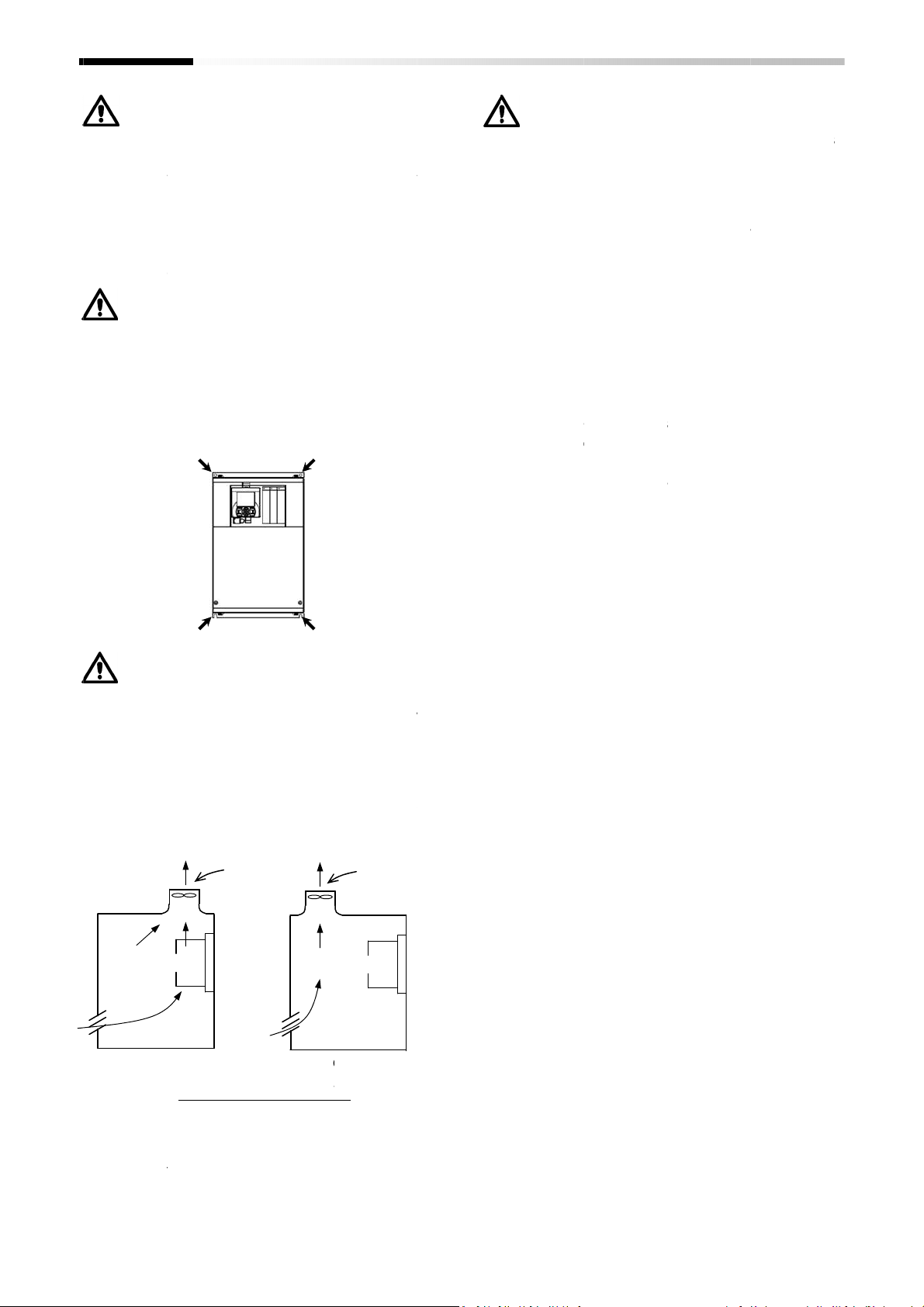
Installation method and position
Install the inverter vertically and securely with
screws or bolts on a surface that is free from
vibrations and that can bear the
If the inverter is not installed properly, its cooling
performance may be degraded and tripping or
inverter damage may result.
Mounting in an enclosure
mounting multiple inverters in an enclosure
with a ventilation fan, carefully design the layout
of the ventilation fan, air intake port, and inverters.
An inappropriate layout will reduce t
inverter
temperature.
inverter ambient temperature will remain within
the range specified in the specification table.
the
the incoming dust may
a position to avoid this falling dust
(Acceptable)
Screw
Screw
gases, flammable gases, grinding fluid
If you use the inverter in
cooling effect and
the layout
inverter is installed
adhere to
Ventilation
Position of ventilation fan
nverter will cause
inverter weight.
raise the ambient
properly
below ventilatio
the inverter.
(Unacceptable)
Inverter
Screw
Screw
a considerably
so that the
n fan,
lace in
Ventilation
Reduction of
External heat sink installation may reduce internal
heat emission
External heat sink mounting for the inverter
-
-
requires an optional
Other models than above can be installed with the
originally attached metal
enclosure panel according to the specified cutting
dimensions.
The cooling s
positioned outside the enclosure has a cooling fan.
Therefore, do not place the enclosure in any
environment where it is exposed to water
oil mist, or dust.
he heat sink part reaches a high temperature.
Install a pr
Installation and Wiring
enclosure size
and reduce the enclosure si
00228
00126
metal
for external heat sink, cut out the
ection (including the heat sink)
otection cover as needed.
004L to P1
007H to P1
. To mount the
037L)
037H)
drops,
•
•
failure
•
•
•
•
P1-00044
of
and
P1-00041
•
inverter
•
•
T
L to P1-
H to P1-
-L (P1-
-H (P1 fitting.
fitting
ze.
-
-
•
When
Inverter
When
he
Plan
.
P
2-3
Page 20

2.3 Dimension Drawing
Chapter 2
If you add optional parts to the inverter, some extra
space is required in the direction of the depth of the
inverter d
clearance of 50 mm or more.
instruction manual for each optional product.
*****
200V class:
00044
0104
00041
00126
*****
200V class:
00330
00175
epending on the wiring layout.
*****
-
L(004L)
, 00080
00156
00054
*****
-
L(055L), 00460
H(055H), 00250
For details, refer
-
L(007L),
L(022L), 00228
00083
H(mm)
-
L(075L), 00600
00310
H(mm)
Keep
to the
D(mm)
140
-
L(110L)
D(mm)
170
g.
VLD rated current
(ND rat
class
Model (P1
200V class:
400V class
Dimension
Model P1
200V class:
400V class:
Dimension
hapter 7
motor capacity is
while H indicates 400V class.
*****
00800
00400
-
01530
00770
Installation and Wiring
Specifications
L(004L) is 4.6A
0.4kW), and L indicates 200V
-
L(150L), 00930
H(150H), 00470
*)
-
L(300L)
for details.
-
L(185L), 01240
00620
-
L(220L)
Model P1-
-* (P1-
-*)
a
(E
) See "C
ed
,
"
for 00046-
,
-
-*)
400V class:
Dimension
Model P1-
-L(015L),
-H(007H),
-H(037H)
W(mm)
150
-* (P1-
-
-H(015H),
-*)
255
-L(037L)
-H(022H),
:
-
W(mm)
245
-H(185H),
H(mm)
390
-H(220H)
D(mm)
190
-*****
* (P1-*****-
400V class:
Dimension
-
W(mm)
210
-H(075H),
260
-H(110H)
-H(300H)
W(mm)
540
H(mm)
300
D(mm)
195
2-4
Page 21

200V class: 01850
-
L(370L), 02290
-
L(450L),
Chapter 2
Installation and Wiring
Model P1-*****-* (P1-*****-*)
400V class: 00930-H(370H),01160-H(450H),01470-H(550H)
Dimension
W(mm) H(mm) D(mm)
550 390 250
Model P1-*****-* (P1-*****-*)
200V class: 02950-L(550L)
Dimension
W(mm) H(mm) D(mm)
700 480 250
Model P1-*****-* (P1-*****-*)
400V class: 01760-H(750H), 02130-H(900H)
Dimension
W(mm) H(mm) D(mm)
700 390 270
(in preparation)
Model P1-*****-* (P1-*****-*)
400V class: 02520-H(1100H), 03160-H(1320H)
Dimension
W(mm) H(mm) D(mm)
740 480 270
(in preparation)
2-5
Page 22

2.
Chapter 2
4
Inverter Wiring
Applicable peripheral equipment
V
W
<12>
<13>
<12>
<13>
No.
<1> Electric wire
<2> Earth-leakage circuit breaker EL
<3> Magnetic contacto
<4> Input
AC
(For harmonic control, power supply
coordination, and power factor
correction)
<5> Noise filter for inverter
<6> Radio noise filter
phase reactor)
<7> Radio noise filter on the input side
(Capacitor filter)
<8> DC
Choke
<9> Braking resistor
<10> Regenerative braking unit
<11> Noise filter on the output side
<12> Radio noise filter
phase reactor)
<13> Output
For reducing vibrations and
preventing thermal relay
malfunction
<14> LCR filter
Notes:
The description of peripheral equipment is for Hitachi 3
Select breakers with proper interrupting capacity. (Use inverter
Use
Use copper electric wire (HIV cable) with allowable temperature rating 75°C or more.
If the power line exceeds 20 m, use cable with ma
Tighten each termina
Loose terminal screws may cause short circuits and fire.
Excessive tightening torque may cause damage to the terminal block or inverter body.
When selecting a rated sensitivity current for earth
separated breaker considering a total cable length of between Inverter
Inverter
Use a delayed
When using a CV cable for wiring through a metal conduit, the average current leakage
would be 30mA/km.
When using a high relative dielectric constant cable such as IV cable, the leakage current is
about eight times as high as the standard cable. Therefore, when using an IV cable, use
ELCB with rated sensitivity current by eight times
cable length exceeds 100 m, use a CV cable.
•Do not pull the power line cable after wiring. Doing so may cause screw loosening.
Name
r MC
reactor
AC reactor
leakage circuit breakers
Motor distance. Do not use a high
type circuit breaker, because the high
See "Recommended cable gauges, wiring accessories,
terminals” on Page 2
C
B or
Use
voltage imbalance exceeds 3% or more, or
capacity is
change rapidly. This reactor also improves the power factor.
This
the inverter and transmitted in cables. Connect this noise filter to
the primary side (input side) of the inverter.
The inverter may generate radio noise through power supply wiring
during operation.
Use this noise filter to reduce the radio noise (radiant noise).
Use this noise filter to reduce the radiant
cables.
Use
Use these devices to increase the braking torque of the inverter for
operation in which the inverter turns the connected
very frequently or decelerates the load running with a high moment
of inertia.
Connect this noise filter between the inverter and motor to reduce
the radiant noise
the electromagnetic interference with radio and television reception
and preventing malfunctions of measuring equipment and sensors.
Use this noise filter to
side of the inverter. (This noise filter can be used on both the input
and output sides.)
I
nverter drive
commercial power supply direct
Connect
the pulsation of motor. Also, connect
cable length between
to prevent thermal relay malfunction due to the harmonic waves
generated by switching operation o
relay can be replaced with a current sensor to avoid the
malfunction.
Connec
the inverter output into a sinusoidal waveform and to reduce the
motor vibration, motor noise and the radiant noise radiated from
cables. Surge voltage can be also controlled.
l screw with the specified tightening torque.
input reactor
500 kVA or more, or when the power voltage may
noise filter reduces the conductive noise that is generated by
DC
chokes
to
nverter drive
n motor may cause large vibrations compared
AC reactor between inverter and motor to lessen
t this noise filter between the inverter and motor to convert
(ELB or MCB)
speed type of earth
Installation and Wiring
Total cable length
100 m or less
300 m or less
Function
for
harmonic wave
reduce
the harmonic generated by the inverter.
radiated from cables for the purpose of reducing
reduce the noise generated on the output
start
inverter and
phase, 4
to ensure safety.
or wire size for the power line.
leakage circu
speed typ
in the table bel
Sensitivity current (mA)
control, or when power supply
when the power supply
noise radiated from input
AC reactor, when the
er
inverter. Note that the thermal
pole squirrel
ready breakers)
it breaker, use a
Power supply and
leakage circuit breaker.
e may malfunction.
ow. If the total
50
100
and crimp
load on and off
to
(10 m or more),
Power
supply
<1>
<3>
<4>
<5>
<2>
•
•
•
earth-
•
•
•
•
–
-
-
•
•
j
-
higher
-
-
-
-cage motor.
-
-
-
R S T
PD
INV
R0
RB
T0
U
M
Motor
<6>
MCCB
-9.
<7>
<8>
P
N
<9>
<10>
(Zero-
over
<11>
<14>
(Zero-
Output
motor.
output
motor is long
f
2-6
Page 23

Symbol
Terminal name
Description
R,S,T
Connect to the AC power supply.
Leave these terminals unconnected
U,V,W
PD,P
DC
choke
Remove the
PD-P
jumper from terminals, and connect the opt
ional
DC
External
chopper
Regenerative
braking
This serves as a ground terminal for the inverter
chassis
to ground.
phase
P+
R/L1
S/L2
T/L3
Control circuit
power supply
Three
-
phase
Main
circuit
terminal section
P
/+ PD
/+1
RB
N/-
Enable
Chapter 2
Installation and Wiring
2.5 Wiring of the main circuit
Wire the main circuit of the inverter.
The following illustration shows the power supply and
wiring connections to a motor only.
Open a terminal block cover to wire the terminal block in
the main circuit.
ThreeAC power
supply
200V class:
200 to 240Vac
400V class:
380 to 500Vac
Earth-leakage
circuit breaker
ELB
Magnetic
contactor
MC
J51 connector
Explanation of main circuit terminal block
Internal EMC filter
Jumper or terminal
Disable
R0
T0
Jumper
U/T1
V/T2
W/T3
Type-D grounding
(200 V class model)
Type-C grounding
(400 V class model)
M
3φ
(L1,L2,L3)
(T1,T2,T3)
(+1,+)
P,RB
(+,RB)
P,N
(+,-)
See “Chapter 1 Safety Instructions” for response to CE and UL
standards.
The screw size may vary depending on terminal. Refer to Page
2-8/2-9 for the size of the terminal screw for the power line cable
while for other terminals, refer to the drawings of the wiring on
Page 2-13 or later.
The tables on Page 2-8/2-9 list the specifications of cables, crimp
terminals, and terminal screw tightening torques for reference.
Recommended wire gauges vary depending on the rated load
settings (ND/LD/VLD).
Main power input
Inverter output Connect a Three-phase motor.
connection terminal
braking resistor
connection terminal
unit connection
terminal
Inverter ground
terminal
when using a regenerative converter.
choke for power factor improvement.
Connect the optional external braking resistor. See “Chapter 7
Specifications” for built-in braking circuit inverter models.
Connect the optional regenerative braking unit.
Connect 200V class and 400V class models to Type-D grounding and
Type-C grounding, respectively.
2-7
Page 24

External braking
Power line cable
Chapter 2
Installation and Wiring
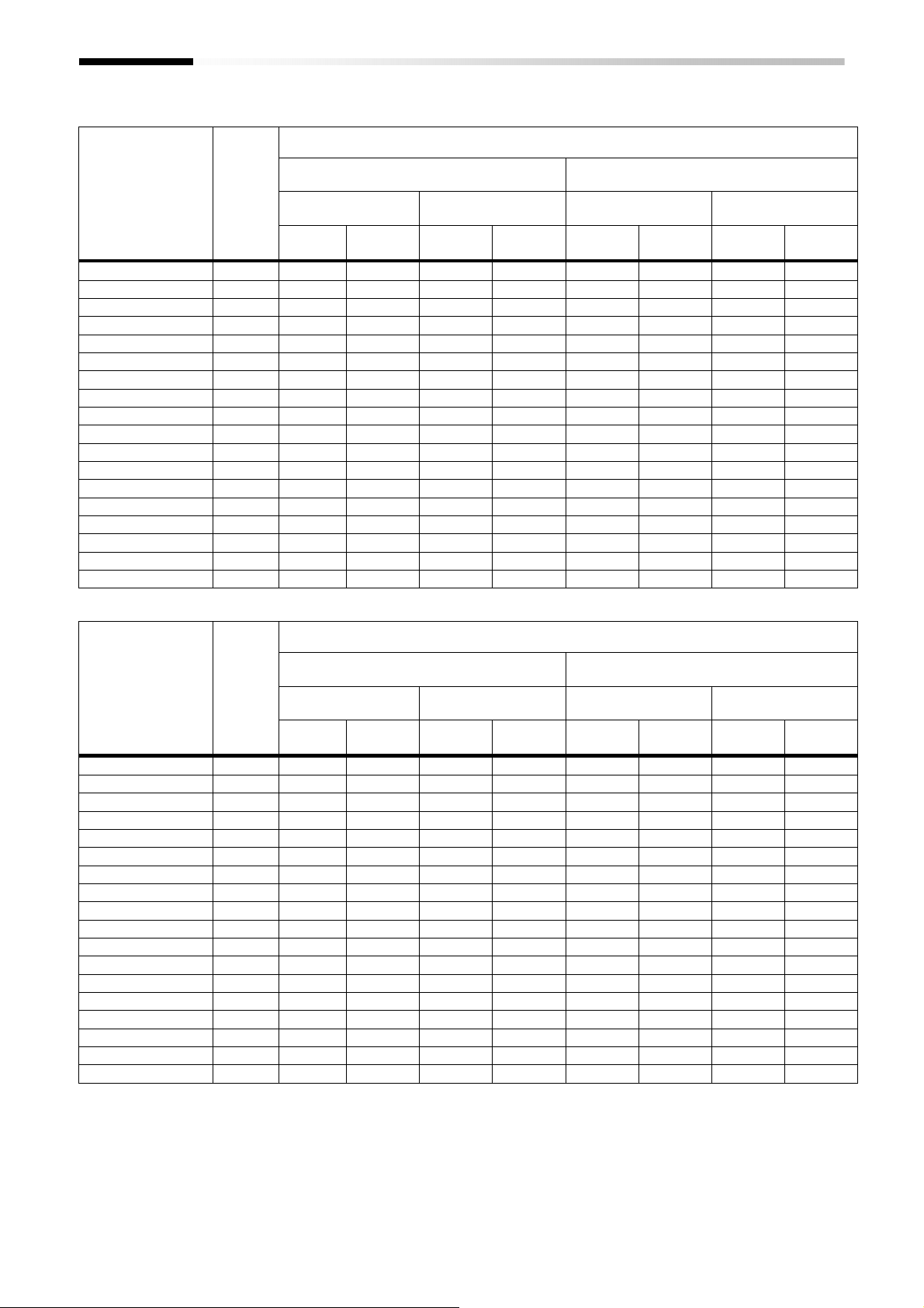
2.6 Recommended wire gauges, wiring
accessories, and crimp terminals
200V class
Applicable P1
inverter model
P1-*******
P1-00044-L
(P1-004L)
P1-00080-L
(P1-007L)
P1-00104-L
(P1-015L)
P1-00156-L
(P1-022L)
P1-00228-L
(P1-037L)
P1-00330-L
(P1-055L)
P1-00460-L
(P1-075L)
P1-00600-L
(P1-110L)
P1-00800-L
(P1-150L)
P1-00930-L
(P1-185L)
P1-01240-L
(P1-220L)
P1-01530-L
(P1-300L)
P1-01850-L
(P1-370L)
P1-02290-L
(P1-450L)
P1-02950-L
(P1-550L)
The wire gauges in the above table shows the designed values
based on HIV cables (with thermal resistance of 75°C).
Rating
setting
ND
VLD
ND
VLD
ND
VLD
ND
VLD 10(5.3) 10(5.3) 10(5.3) 5.5-4/5.5-4
ND
VLD
ND
VLD
ND
VLD 6(13.3) 6(13.3) 14-5/8-5
ND 6(13.3)
VLD
ND 4(21.2)
VLD
ND 3(26.7)
VLD 1(42.4) 1(42.4)
ND 1(42.4)
VLD 2/0(67.4) 2/0(67.4) 70-8/14-6
ND 2/0(67.4)
VLD
ND 4/0(107.2)
VLD
ND
VLD 2/0×2(67.4×2) 70-8/22-8
ND 350kc(177)
VLD
Power line cable
AWG(mm2)
R,S,T,U,V,W,
P,PD,N
14(2.1) 14(2.1) 14(2.1) M4 2-4/2-4 1.4 LD
14(2.1)
14(2.1)
14(2.1) 14(2.1) 14(2.1)
10(5.3) 10(5.3) 10(5.3) M4 5.5-4/5.5-4
8(8.4) 8(8.4) 8(8.4) M5 8-5/8-5 3.0 LD
8(8.4)
4(21.2) 4(21.2) 22-6/14-6
3(26.7) 3(26.7) 38-6/14-6
1/0×2(53.5×2) 60-8/22-8
1/0×2(53.5×2) 60-8/22-8
1/0×2(53.5×2)
3/0×2(85.0×2) 80-8/38-8
Grounding
cable
AWG(mm2)
14(2.1)
14(2.1)
6(13.3)
6(13.3)
6(13.3)
6(13.3)
6(13.3)
4(21.2) ― M8
4(21.2) ― M8
4(21.2) ― M8
3(26.7) ― M10
resistor
between P and
RBAWG(mm2)
14(2.1) M4 2-4/2-4 1.4 LD
14(2.1) M4 2-4/2-4 1.4 LD
8(8.4)
6(13.3)
4(21.2)
3(26.7)
1(42.4)
Please use the round type crimp terminals (for the UL standard)
suitable for the use electric wire when you connect the electric
wire with the main circuit terminal block. Please put on pressure
to the crimp terminals with a crimp tool that the crimp terminal
maker recommends.
Terminal screw
size
M4
M5
M6
M6
M6
M8
Crimp
terminal
2-4/2-4
8-5/8-5
14-6/14-6
22-6/14-6
38-6/14-6
60-6/14-6
60-8/14-6
70-8/22-8
100-8/22-8
60-8/22-8
180-8/38-8
Tightening
torque
N•m
1.4 LD
1.4 LD
3.0 LD
4.0 LD
2.5 to 3.0 LD
2.5 to 3.0 LD 2(33.6) 2(33.6)
5.5 to 6.6 LD 1/0(53.5) 1/0(53.5)
6.0 LD
15.0 LD
6.0 to 10.0 LD
19.6 LD
2-8
Page 25

External braking
Power line cable
Chapter 2
Installation and Wiring
400V class
Applicable P1
inverter model
P1-*******
P1-00041-H
(P1-007H)
P1-00054-H
(P1-015H)
P1-00083-H
(P1-022H)
P1-00126-H
(P1-037H)
P1-00175-H
(P1-055H)
P1-00250-H
(P1-075H)
P1-00310-H
(P1-110H)
P1-00400-H
(P1-150H)
P1-00470-H
(P1-185H)
P1-00620-H
(P1-220H)
P1-00770-H
(P1-300H)
P1-00930-H
(P1-370H)
P1-01160-H
(P1-450H)
P1-01800-H
(P1-550H)
P1-02160-H
(P1-750H)
P1-02600-H
(P1-900H)
P1-03250-H
(P1-1100H)
P1-03610-H
(P1-1320H)
The wire gauges in the above table shows the designed values
based on HIV cable (with thermal resistance of 75°C).
Rating
setting
ND
VLD
ND
VLD
ND
VLD
ND
VLD 12(3.3) 12(3.3) 12(3.3) 5.5-4/5.5-4
ND
VLD 10(5.3) 10(5.3) 10(5.3)
ND
VLD 8(8.4) 8(8.4) 8(8.4) 8-5/8-5
ND
VLD
ND
VLD
ND 8(8.4)
VLD
ND 6(13.3)
VLD
ND 3(26.7)
VLD 1(42.4) 60-8/14-8
ND
VLD
ND 1(42.4)
LD 1/0(53.5)
VLD 2/0(67.4) 70-8/14-8
ND 2/0(67.4)
LD
VLD
ND
VLD
ND
VLD
ND
VLD
ND
VLD
Power line cable
AWG(mm2)
R,S,T,U,V,W,
P,PD,N
14(2.1) 14(2.1) 14(2.1) M4 2-4/2-4 1.4 LD
14(2.1) 14(2.1) 14(2.1) M4 2-4/2-4 1.4 LD
14(2.1) 14(2.1) 14(2.1) M4 2-4/2-4 1.4 LD
14(2.1) 14(2.1) 14(2.1)
12(3.3) 12(3.3) 12(3.3)
10(5.3) 10(5.3) 10(5.3)
8(8.4) 8(8.4) 8(8.4) M6 8-6/8-6 4.0 LD
8(8.4) 8(8.4) 8(8.4) M6 8-6/8-6 4.0 LD
6(13.3) 6(13.3) 14-6/8-6
4(21.2) 4(21.2) 22-6/8-6
1(42.4) 6(13.3) - M8 60-8/14-8 15.0 LD
1/0×2(53.5×2) 60-8/22-8
― ― ― ― ― ― LD
― ― ― ― ― ― LD
― ― ― ― ― ― LD
― ― ― ― ― ― LD
Grounding
cable
AWG(mm2)
8(8.4)
8(8.4)
6(13.3) - M8
6(13.3) - M8
4(21.2) - M8
resistor
between P and
RBAWG(mm2)
8(8.4)
6(13.3)
Please use the round type crimp terminals (for the UL standard)
suitable for the use electric wire when you connect the electric
wire with the main circuit terminal block. Please put on pressure
to the crimp terminals with a crimp tool that the crimp terminal
maker recommends.
Terminal screw
size
M4
M5 5.5-5/5.5-5
M5
M6
M6
Crimp
terminal
2-4/2-4
5.5-5/5.5-5
8-6/8-6
14-6/8-6
38-8/14-8
60-8/14-8
70-8/22-8
Tightening
torque
N•m
1.4 LD
3.0 LD
3.0 LD
4.0 LD
4.0 LD
6.0 LD 2(33.6)
6.0~10.0
6.0~10.0
2-9
Page 26

(DCL or
ACL)
(DCL or
ACL)
(ELB)
(MC)
(ELB)
(MC)
model
Rate
model
Rate
P1-00044
-
L(P1-004L) 0.4 EB-30E 5 HS8 HS8 EB-30E 5 HS8 HS8
P1-00080
-
L(P1-007L) 0.75 EB-30E 10 HS8 HS8 EB-30E 5 HS8 HS8
P1-00104
-
L(P1-015L) 1.5 EB-30E 15 HS8 HS8 EB-30E 10 HS8 HS8
P1-00156
-
L(P1-022L) 2.2 EB-30E 20 HS8 HS8 EB-30E 15 HS8 HS8
P1-00228
-
L(P1-037L) 3.7 EB-30E 30 HS8 HS20 EB-30E 20 HS8 HS20
P1-00330
-
L(P1-055L) 5.5 EB-50E 40 HS20 HS25 EB-30E 30 HS8 HS20
P1-00460
-
L(P1-075L) 7.5 EB-50E 50 HS35 HS35 EB-50E 40 HS20 HS25
P1-00600
-
L(P1-110L) 11 EB-100E 75 HS50 H65C EB-100E 60 HS35 HS50
P1-00800
-
L(P1-150L) 15 RXK125
-S
125 H65C H80C EB-100E 100 HS50 H65C
P1-00930
-
L(P1-185L) 18.5 RXK125
-S
125 H80C H100C
EB-
100E 100 HS50 H65C
P1-01240
-
L(P1-220L) 22 EXK225
150 H80C H125C
RXK125
-S
125 H65C H80C
P1-01530
-
L(P1-300L) 30 EXK225
200 H125C
H150C
EXK225
150 H80C H125C
P1-01850
-
L(P1-370L) 37 RXK250
-S
250 H150C
H200C
EXK225
200 H100C
H125C
P1-02290
-
L(P1-450L) 45 EX400
300 H200C
H250C
EXK225
225 H125C
H150C
P1-02950
-
L(P1-550L) 55 EX400
400 H200C
H300C
EX400
300 H150C
H250C
(DCL or ACL)
(DCL or ACL)
(ELB)
(MC)
(ELB)
(MC)
model
Rate
model
Rate
P1-00044
-
L(P1-004L) 0.75 EB-30E 10 HS8 HS8 EB-30E 5 HS8 HS8
P1-00080
-
L(P1-007L) 1.5 EB-30E 15 HS8 HS8 EB-30E 10 HS8 HS8
P1-00104
-
L(P1-015L) 2.2 EB-30E 20 HS8 HS8 EB-30E 15 HS8 HS8
P1-00156
-
L(P1-022L) 3.7 EB-30E 30 HS8 HS20 EB-30E 20 HS8 HS20
P1-00228
-
L(P1-037L) 5.5 EB-50E 40 HS20 HS25 EB-30E 30 HS8 HS20
P1-00330
-
L(P1-055L) 7.5 EB-50E 50 HS35 HS35 EB-50E 40 HS20 HS25
P1-00460
-
L(P1-075L) 11 EB-100E 75 HS50 H65C EB-100E 60 HS35 HS50
P1-00600
-
L(P1-110L) 15 RXK125
-S
125 H65C H80C EB-100E 100 HS50 H65C
P1-00800
-
L(P1-150L) 18.5 RXK125
-S
125 H80C H100C
EB-
100E 100 HS50 H65C
P1-00930
-
L(P1-185L) 22 EXK225
150 H80C H125C
RXK125
-S
125 H65C H80C
P1-01240
-
L(P1-220L) 30 EXK225
200 H125C
H150C
EXK225
150 H80C H125C
P1-01530
-
L(P1-300L) 37 RXK250
-S
250 H150C
H200C
EXK225
200 H100C
H125C
P1-01850
-
L(P1-370L) 45 EX400
300 H200C
H250C
EXK225
225 H125C
H150C
P1-02290
-
L(P1-450L) 55 EX400
400 H200C
H300C
EX400
300 H150C
H250C
P1-02950
-
L(P1-550L) 75 EX600B
500 H300C
H400C
EX400
400 H200C
H300C
Chapter 2
Installation and Wiring
2.7 Applicable circuit breaker
200V class
• For ND rating
Model
P1-*******
(P1-****)
Applicable
Motor
(kW)
Earth-leakage breaker
Example
Without reactor
Current
Applicable devices (Input Voltage 200~220V)
Magnetic Contactor
AC-1 AC-3
Earth-leakage breaker
Example
Current
With reactor
Magnetic Contactor
AC-1 AC-3
• For LD/VLD rating
Model
P1-*******
(P1-****)
Applicable
Motor
(kW)
Earth-leakage breaker
Example
Without reactor
Current
Applicable devices(Input Voltage 200~220V)
Magnetic Contactor
AC-1 AC-3
Earth-leakage breaker
Example
With reactor
Current
Magnetic Contactor
AC-1 AC-3
Device model name on above table shows example selection. The
device selection should be made in base on rated current, short
circuit current capability and accordance to the local electrical
legislation.
Applicable motor capacity is based on Hitachi 200Vac, 60Hz, 4 pole
IE3 motor.
Refer to the wire gauge table on chapter 2-8 for power line cable.
Electrical endurance for AC-1 magnetic contactor is 500000 times,
however, for emergency stop in motor operation will be only 25
times.
Select AC-3 class magnetic contactor for inverter output for
application which has an emergency stop or commercial power line
operation.
When selecting oversize inverter capacity compare to motor rating,
select magnetic contactor according to the inverter capacity
2-10
Page 27
(DCL or ACL)
(DCL
or ACL)
(ELB)
(MC)
(ELB)
(MC)
model
Rate
model
Rate
P1-00041
-
H(P1-007H) 0.75 EX50C
5
HS8 HS8 EX50C
5
HS8 HS8
P1-00054
-
H(P1-015H) 1.5 EX50C
10
HS8 HS8 EX50C
5
HS8 HS8
P1-00083
-
H(P1-022H) 2.2 EX50C
10
HS8 HS8 EX50C
10
HS8 HS8
P1-00126
-
H(P1-037H) 3.7 EXK50
-C 15
HS8 HS10 EX50C
10
HS8 HS10
P1-00175
-
H(P1-055H) 5.5 EXK50
-C 20
HS8 HS20 EXK50
-C 15
HS8 HS20
P1-00250
-
H(P1-075H) 7.5 EXK50
-C 30
HS8 HS25 EXK50
-C 20
HS20 HS25
P1-00310
-
H(P1-110H) 11 EXK50
-C 40
HS20 HS35 EXK50
-C 30
HS25 HS35
P1-00400
-
H(P1-150H) 15 EXK50
-C 50
HS25 HS50 EXK50
-C 40
HS35 HS50
P1-00470
-
H(P1-185H) 18.5 EXK100
-C 75
HS35 HS50 EXK50
-C 50
HS50 HS50
P1-00620
-
H(P1-220H) 22 EXK100
-C 75
HS50 H65C EXK60
-C 60
HS50 H65C
P1-00770
-
H(P1-300H) 30 EXK100
-C
100 HS50 H80C EXK100
-C 75
H80C H80C
P1-00930
-
H(P1-370H) 37 RXK125
-S
125 H80C H100C
EXK100
-C
100 H80C H100C
P1-01160
-
H(P1-450H) 45 EXK225
150 H80C H125C
RXK125
-S
125 H100C
H125C
P1-01470
-
H(P1-550H) 55 EXK225
200 H100C
H125C
EXK225
150 H150C
H125C
P1-01760
-
H(P1-750H) 75 RXK250
-S
250 H150C
H200C
EXK225
200 H200C
H200C
P1-02130
-
H(P1-900H) 90 EX400
300 H200C
H250C
EXK225
225 H200C
H250C
P1-02520
-
H(P1-1100H)
110 EX400
400 H200C
H300C
EX400
300 H250C
H300C
P1-03160
-
H(P1-1320H)
132 EX600B
500 H250C
H300C
EX400
350 H400C
H400C
(DCL or ACL)
(DCL or ACL)
(ELB)
(MC)
(ELB)
(MC)
model
Rate
model
Rate
P1-00041
-
H(P1-007H) 1.5 EX50C
10
HS8 HS8 EX50C
5
HS8 HS8
P1-00054
-
H(P1-015H) 2.2 EX50C
10
HS8 HS8 EX50C
10
HS8 HS8
P1-00083
-
H(P1-022H) 3.7 EXK50
-C 15
HS8 HS10 EX50C
10
HS8 HS8
P1-00126
-
H(P1-037H) 5.5 EXK50
-C 20
HS8 HS20 EXK50
-C 15
HS8 HS20
P1-00175
-
H(P1-055H) 7.5 EXK50
-C 30
HS8 HS25 EXK50
-C 20
HS8 HS20
P1-00250
-
H(P1-075H) 11 EXK50
-C 40
HS20 HS35 EXK50
-C 30
HS8 HS25
P1-00310
-
H(P1-110H) 15 EXK50
-C 50
HS25 HS50 EXK50
-C 40
HS20 HS35
P1-00400
-
H(P1-150H) 18.5 EXK100
-C 75
HS35 HS50 EXK50
-C 50
HS20 HS35
P1-00470
-
H(P1-185H) 22 EXK100
-C 75
HS50 H65C EXK60
-C 60
HS35 HS50
P1-00620
-
H(P1-220H) 30 EXK100
-C
100 HS50 H80C EXK100
-C 75
HS50 H65C
P1-00770
-
H(P1-300H) 37 RXK125
-S
125 H80C H100C
EXK100
-C
100 HS50 H65C
P1-00930
-
H(P1-370H) 45 EXK225
150 H80C H125C
RXK125
-S
125 H65C H80C
P1-01160
-
H(P1-450H) 55 EXK225
200 H100C
H125C
EXK225
150 H80C H100C
P1-01470
-
H(P1-550H) 75 EX400
250 H150C
H200C
EXK225
200 H100C
H125C
P1-01760
-
H(P1-750H) 90 EX400
300 H200C
H250C
EXK225
225 H125C
H150C
P1-02130
-
H(P1-900H) 110 EX400
400 H200C
H300C
EX400
300 H150C
H250C
P1-02520
-
H(P1-1100H)
132 EX600B
500 H250C
H300C
EX400
350 H200C
H250C
P1-03160
-
H(P1-1320H)
160 EX600B
600 H400C
H400C
EX400
400 H250C
H300C
Chapter 2
Installation and Wiring
400V class
• For ND rating
Model
P1-*******
(P1-****)
Applicable
Motor
(kW)
Without reactor
Earth-leakage breaker
Example
Current
Applicable devices (Input Voltage 400~440V)
Magnetic Contactor
AC-1 AC-3
Earth-leakage breaker
Example
Current
With reactor
Magnetic Contactor
AC-1 AC-3
• For LD/VLD rating
Model
P1-*******
(P1-****)
Applicable
Motor
(kW)
Without reactor
Earth-leakage breaker
Example
Current
Applicable devices (Input Voltage 400~440V)
Magnetic Contactor
AC-1 AC-3
Earth-leakage breaker
Example
Current
With reactor
Magnetic Contactor
AC-1 AC-3
Device model name on above table shows example selection. The
device selection should be made in base on rated current, short
circuit current capability and accordance to the local electrical
legislation.
Applicable motor capacity is based on Hitachi 400Vac, 60Hz, 4 pole
IE3 motor.
Refer to the wire gauge table on chapter 2-8.
Electrical endurance for AC-1 magnetic contactor is 500000 times,
however, for emergency stop in motor operation will be only 25
times.
Select AC-3 class magnetic contactor for inverter output for
application which has an emergency stop or commercial power line
operation.
When selecting oversize inverter capacity compare to motor rating,
select according to the inverter capacity
2-11
Page 28

Braking
Resistor
(kW)
00080
-L
00104
-L
00156
-L
00228
-L
00330
-L
00460
-L
00600
-L
RB2 ×3
00800
-L
RB3 ×2
00930
-L
RB3 ×2
01240
-L
RB3 ×3
Braking
Resistor
Usage
(kW)
00054
-H
SRB200
-1
00083
-H
SRB200
-2
00126
-H
SRB300
-1
00175
-H
SRB300
-1
00250
-H
SRB400
-1
RB1
RB2
RB2
RB1
RB3
RB3
01160
-H
CA-KB
01800
-H
CA-KB
Chapter 2
Installation and Wiring
2.8 Chopper Braking Resistor
•
SJ Series P1 has a built-in chopper braking circuit in model below.
P1-00044-L (004L) to P1-01240-L (022L)
P1-00041-H (007H) to P1-00930-H (370H)
•
By using an optional braking resistor, permit to use for high
regeneration load application such as lift or high speed load.
200V class
Appli
Model
P1-******
(P1-****)
00044-L
(004L)
(007L)
(015L)
(022L)
(037L)
(055L)
(075L)
(110L)
(150L)
(185L)
(220L)
When using RB2×2series×2parallel, will require in total 4 RB2 units.
Min.
Resis
tor
(Ω)
Resistor
selection
Ex. (Ω)
Model
parallel
parallel
parallel
parallel
cable
motor
(kW)
0.4 50 180 SRB200-1 10 0.7 0.2
0.75 50 100 SRB200-1 10 0.7 0.2
1.5 35 100 SRB200-2 7.5 1.25 0.2
2.2 35 50 SRB300-1 7.5 2.5 0.3
3.7 35 35 SRB400-1 7.5 3.6 0.4
5.5 16 17 RB3 10 7.7 1.2
7.5 10 17 RB3 10 7.7 1.2
11 10 11.7
15 7.5 8.5
18.5 7.5 8.5
22 5 5.7
Short
Usage
period
ratio
(%)
10 11.4 1.8
10 15.4 2.4
10 15.4 2.4
10 23.1 3.6
capacity
capacity
Rated
(kW)
•
SJ Series P1 can offer when desired a built-in chopper braking circuit
in models below.
P1-01160-H (450H) to P1-01470-H (550H)
•
Using optional braking unit or regenerative unit, permit to use on
high regenerative load application even for models without built-in
chopp er braking circuit.
•
The table below shows an example selection of braking resistor to
output 100% of braking torque for each motor rating on list.
■400V
Appli
Model
P1-******
(P1-****)
00041-H
(007H)
(015H)
(022H)
(037H)
(055H)
(075H)
00310-H
(110H)
00400-H
(150H)
00470-H
(185H)
00620-H
(220H)
00770-H
(300H)
00930-H
(370H)
(450H)
(550H)
motor
Min.
Resis
tor
(Ω)
Resistor
selection
Ex. (Ω)
cable
(kW)
0.75 100 360
1.5 100 100
2.2 100 100
3.7 70 100
5.5 70 100
7.5 35 70
11 35 50
15 24 35
18.5 24 35
22 20 25
30 15 17
37 15 17
45 10 10
55 10 10
Model
SRB200-1
×2series
×2series
×2series
×2 series
×2 series
×2 series
×2 series
×2 parallel
×2 series
×2parallel
×2 series
×2parallel
×2 series
×4parallel
×2 series
×2parallel
×2 series
×2parallel
(10Ω5unit)
(10Ω5unit)
Short
period
ratio
capacity
(%)
10 1.4 0.4
10 1.4 0.4
7.5 2.5 0.4
7.5 5 0.6
7.5 5 0.6
7.5 7.2 0.8
10 10.4 1.6
10 15.2 2.4
10 15.2 2.4
10 20.8 3.2
10 30.8 4.8
10 30.8 4.8
10 45 17
10 45 17
Rated
capacity
(kW)
2-12
Page 29
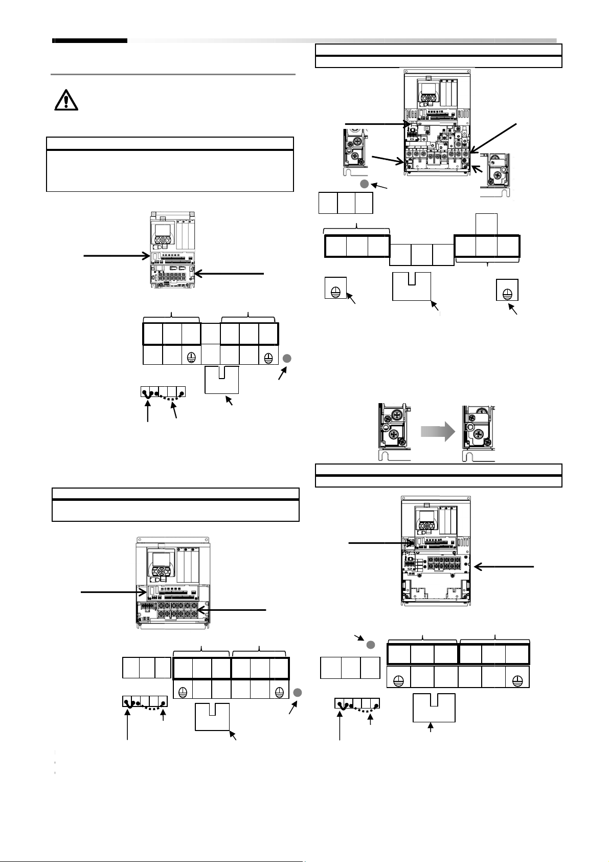
2.9
00044
00104
00228
00054
00126
Screw size
Model
200V class:
400V class:
00330
00175
Screw size
R0,T0 : M4
Ground terminal
Other terminal
00600
Screw size
R0,T0 : M4
Ground terminal
Other terminal
Control circuit termina
Chapter 2
Wiring
When J51 connector is removed, charge lamp
indicate R0
and care for safety
off before handling the inverter.
M4
: M4
Control circuit termina
EMC jumper
Model
P1- *****
200V class: 00330
400V class: 00175
EMC jumper
*****
00044
00156
00041
00126
: M5
: M5
: M6
: M6
T0 status. Please make sure that power is off
. For
(L1)
filter
disabled
G ON
Power input line
enable
-*(P1-****)
-
L(055L), 00460
H(055H), 00250
to enable
-
L(004L), 00080
L(022L),00228
H(007H), 00054
EMC filter
enabled
T0
ON
safety, make sure to power
(L2)
(L3)
(RB)
(+1)
Motor output line
ain circuit terminal
disable the EMC filter.
-
L(075L), 00600
H(075H), 00310
disable the EMC filter.
-
L(007L), 00104
-
083
Power input line
(L1)
S (L2)
T(L3)
(+1)
P(+)
M
doesn't
(T1)
(T2)
(T3)
(+)
(-)
Charge lamp
on while
energized)
-
L(110L)
L(015L),
Motor output line
(T1)
(T2) (T3)
(-)
(RB)
Charge lamp
on while
energized)
ain circuit terminal
Model
200V class: 00800
Model
400V class:
R0
(L1)
R0
Ground terminal to enable
the EMC filter function
00800
Screw size
R0,T0 : M4
Ground terminal: M6
Other terminals : M6
Control circuit termina
Charge lamp
(Turn
energized)
P1- *****-*
(P1
-
L(150L)/00930
To enable or disable
EMC jumper of the ground terminal.
P1- *****-*
(P1
00400
-
H(150H), 00470
Switching the short
EMC filter
enabled
disabled
Power input line
(L2)
(L3)
Control circuit
Installation and Wiring
-
****)
-
L(185L)/01240
the EMC filter, insert or remove the
-
****)
-
H(185H), 00620
circuit connector can enable/disable the
(L3)
P Jumper
Power input line
(+1)
P (+) (
PD
Screw size
R0,T0 : M4
Ground terminal: M6
Other terminals : M8
-
L(220L)
-
H(220H)
Screw size
R0,T0 : M4
Ground terminal: M6
Other terminal: M6
(T1)
V(T2)
RB
(RB)
Motor output line
Motor output line
(T1)
(T2)
(-)
(RB)
Ground terminal
(
ain circuit terminal
ain circuit terminal
(T3)
(T3)
(With jumper)
Fix the jumper by
own
terminal
M
P1-
-L/00080-L/
-L/00156-L/
-L/00041-H/
-H/00083-H/
-H
R0,T0: M4
Ground terminal:
Other terminals
Switch
-*(P1-****)
-
-
-H(037H)
l
R0
OFF
EMC
to
R
-L(037L)
-H(015H), 00
S
T
T0 G
EMC filter
enabled
or
M
RB
PD
-H(022H),
U
V
P
N
(Turn-
PD-P Jumper
RB
V
W
G
with jumper)
using 2 screws.
Ground
terminal
T0
Charge lamp
(Turn-on while
energized)
T
PD
N
PD-P Jumper
01240-L
R S
G
W
G
-L/00930-L
U
-L/00460-L/
-H/00250-H
-L/00310-H
Switch
-
OFF G
EMC filter
disabled
l
R0
-
R
G
PD
-H(110H)
U
N
V
RB
(Turn-
l
M
-on while
W
G
T0
OFF G ON
EMC filter
(L1)
G
R
S
T
U
N
(-)
W
G
(L2)
(L3)
PD
(+1)
PD-
P
(+)
EMC filter.
-
or
2-13
Page 30
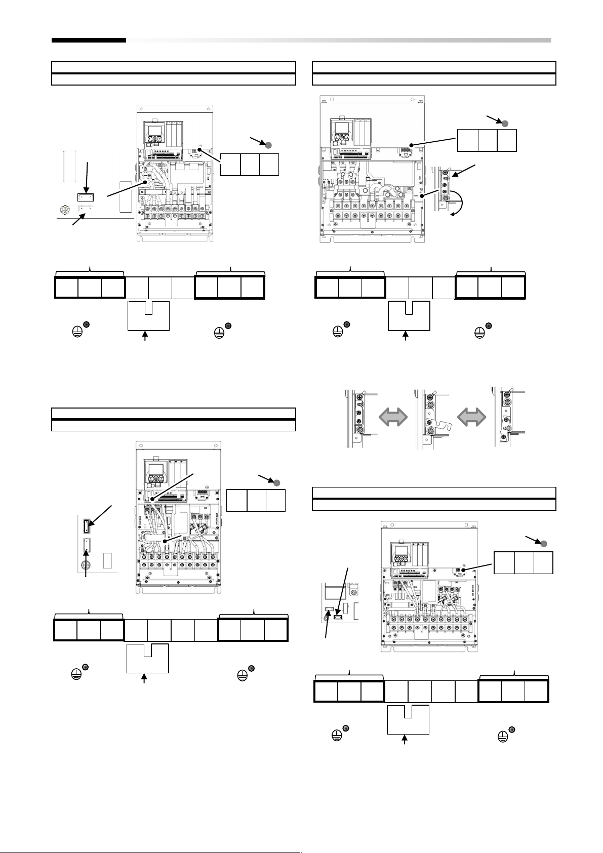
Model P1
- *****-*(P1-****)
200V class: 01
530-
L(300L)
Other Terminal
: M8
Model P1
- *****-*(P1-****)
400V class: 00
770-H(300H)
Other terminals: M8
PD-P Jumper
Model P1
- *****-*(P1-****)
200V class: 01850
-
L(370L)
Other Terminal
: M8
Model P1
- *****-*(P1-****)
400V class: 00930
-
H(370H)
PD-P Jumper
Other : M8
Chapter 2
Installation and Wiring
Jumper bar for
EMC filter
Disable
Enable
Power Line Input Line
R
S
(L1)
(L2)
G
T
(L3)
PD
(+1)
(+)
Charge Lamp
Charge Lamp
R0 T0
Screw size
R0,T0 : M4
Ground Terminal: M6
Motor Output Line
P
N
U
V
(-)
(T1)
(T2)
W
(T3)
G
Power Line Input Line
R
S
T
(L1)
(L2)
(L3)
G
PD
(+1)
P
(+)
R0
disabled
enables
EMC
filter short bar
Screw Size
R0,T0 : M4
Ground terminal : M8
Motor Output Line
N
U
(-)
(T1)
G
V
(T2)
T0
W
(T3)
Switch the jumper bar to enable or disable the EMC filter.
Jumper bar for
EMC Filter
enabled
Power input line
R
S
(L1)
(L2)
G
Disabled
T
(L3)
PD
(+1)
P
(+) N (-)
Charge Lamp
Screw size
R0,T0: M4
Ground terminal: M8
Motor output line
RB
U
(RB)
(T1)
R0 T0
V
(T2)
(T3)
G
W
Switch the jumper bar to enable or disable the EMC filter.
Disable Switching(screw) Enable
EMC
Filter Short bar
disabled
Screw size
enables
Power input line
Charge lamp
R0 T0
R0,T0 : M4
Ground Terminal : M8
Motor output line
Switch the jumper bar to enable or disable the EMC filter.
P
(+) N (-)
RB
(RB)
(L1)
R
S
T
(L3)
PD
(+1)
(L2)
G
Switch the jumper bar to enable or disable the EMC filter.
2-14
(T1)
U
V
W
(T2)
(T3)
G
Page 31

Model P1
- *****-*(P1-****)
200V class: 02290
-
L(450L)
Other terminals: M8
Model P1
- *****-*(P1-****)
400V class: 01160
-
H(450H)
Other terminals: M8
Model P1
- *****-*(P1-****)
200V class: 02
590-L(5
50L)
Other terminals: M8
Model P1
- *****-*(P1-****)
400V class: 01
470-H(5
50H)
Other terminals: M8
Chapter 2
Installation and Wiring
Input power line
R
S
(L1)
(L2)
G
(L3)
Charge lamp
(Turn-on while
energized)
R0
Disable
T0
Jumper bar
for EMC filter
Enable
Screw size
R0,T0: M4
Ground terminal: M8
Motor output line
T
PD
(+1)
P
(+) N (-)
U
(T1)
G
(T2)
V
W
(T3)
Input power line
R
S
(L1)
(L2)
(L3)
G
T
PD
(+1)
Charge lamp
(Turn-on while
energized)
Disable
Enable
P
(+) N (-)
R0
T0
Jumper bar
for EMC filter
Screw size
R0,T0: M4
Ground terminal: M8
Motor output line
U
V
(T1)
(T2)
G
W
(T3)
PD-P Jumper
Switch the jumper bar to enable or disable the EMC filter.
Charge lamp
(Turn-on while
energized)
R0
Disable
T0
Jumper bar
for EMC filter
Enable
Screw size
R0,T0: M4
Ground terminal: M8
Input power line
R
S
(L1)
(L2)
(L3)
T
PD
P
(+1)
(+) N (-)
Motor output line
RB
U
(RB)
(T1)
(T2)
V
W
(T3)
PD-P Jumper
Switch the jumper bar to enable or disable the EMC filter.
Charge lamp
(Turn-on while
energized)
R0
Disable
Jumper bar
for EMC filter
Enable
Screw size
R0,T0: M4
Ground terminal: M8
Input power line
Motor output line
T0
G
PD-P Jumper
G
Switch the jumper bar to enable or disable the EMC filter.
Disable Switching(screw) Enable
R
S
T
PD
(L1)
(L2)
(L3)
G
PD-P Jumper
(+1)
P
(+) N (-)
U
(T1)
Switch the jumper bar to enable or disable the EMC filter.
2-15
G
(T2)
V
W
(T3)
Page 32

Model P1
- *****-*(P1-****)
200V class: 0
1760-H(750H)
Model P1
- *****-*(P1-****)
400V class: 0
2130-H(900H)
Model P1
- *****-*(P1-****)
200V class: 0
2520-H(
1100H
)
Model P1
- *****-*(P1-****)
400V class: 0
3160-H(
1320H)
Chapter 2
Installation and Wiring
(In preparation)
(In preparation)
(In preparation)
(In preparation)
2-16
Page 33

Label Switch Name
Description
It c
hanges
the input specification
of Analog input 1
It c
hanges
the input
specification of Analog input 2
It c
hanges
the output specification of Analog output 1
It c
hanges
the output specification of Analog output 2
It c
hanges
the power
source for
input terminals.
It changes the s
ink or source logic
for
input terminal
.
P+
2/SCHG
Ai1
L
Ao1
Ao2
L
SP
SN
SP
SN
RP
L
10V
20mA
10V
10V
20mA
20mA
Functional safety input
STO input
P24
P24
(SW3)
Chapter 2
Installation and Wiring
2.10 Wiring of the control circuit
An example for sink logic.
24V power
supply terminal
Sink or source logic
for input terminal is
switched by SW6.
Input terminals
Analog
input 1
Analog
input 2
Analog
input 3
(+)
(-)
(±)
(0)
Thermistor
Switch configuration
Ai1
(SW1)
Ai2
(SW2)
Ao1
(SW3)
Ao2
(SW4)
P.SEL
(SW5)
(SW6)
Analog input 1
switch
Analog input 2
switch
Analog output 1
switch
Analog output 2
switch
Power supply
input switch
Input terminal
Sink/Source
logic switching
SRC/SINK
(Ai1 terminal).
10V: Voltage input is available.
20mA: Current input is available.
(Ai2 terminal).
10V: Voltage input is available.
20mA: Current input is available.
(Ao1 terminal).
10V: Voltage output is applied.
20mA: Current output is applied.
(Ao2 terminal).
10V: Voltage output is applied.
20mA: Current output is applied.
IN: Internal power source.
EX: External power source.
(While setting EX, it requires an external power supply
between input terminals and COM terminal)
Is enabled when SW5 is in IN position.
SINK: Switch to Sink logic.
SRC: Switch to Source logic.
P-
1/RS
3/JG
4/FRS
5/2CH
6/CF1
7/CF2
8/RV
9/FW
A/EXT
B/USP
COM
H
Ai2
Ai3
P24S
STC
CMS
ST1
ST2
TH+
TH-
Control circuit terminal
(SW5)
IN
EX
(SW1)
Voltage input
Current input
Voltage input
Current input
(SW2)
section
(SW6)
Sink
Source
AL0
CM1
(SW4)
DC24V
16/ZS
11/RUN
12/FA1
13/FA2
14/RDY
15/OL
20mA
10V
P24
CM1
AL1
AL2
16A
16C
CM2
L
P24
FM
CM1
ED+
ED-
Alarm relay
1C contact points
Relay
1A contact points
Output terminals
*Sink/source supported
Interface
24V power source terminal
Functional safety
confirmation output
STO output
(SW4) (SW3) (SW2) (SW1) (SW5) (SW6)
Ao2
20mA
SW4
10V
Ao1
20mA
SW3
10V
Ai2
20mA
SW2
10V
Ai1 P.SEL
20mA
SW1
10V
Control circuit terminal
Make sure to power-off previous to change any
switches. Otherwise, may damage the inverter.
RS485
SW5
EX
IN
SRC
SW6
SINK
2-17
Page 34

Ferrule
terminal
Push the
gray part into
the socket with a slotted
Insert the wire
The wire is connected
Chapter 2
Installation and Wiring
■
Recommended terminals for wiring
• The following ferrule terminals are recommended for
signal cable for easy wiring and improved reliability of
connectivity.
Ferrule terminal with sleeves
Power cable size
mm2 (AWG)
0.25 (24) AI 0,25-8YE 8 12.5 0.8 2.0
0.34 (22) AI 0,34-8TQ 8 12.5 0.8 2.0
0.5 (20) AI 0,5-8WH 8 14 1.1 2.5
0.75 (18) AI 0,75-8GY 8 14 1.3 2.8
*) Manufacturer: Phoenix Contact
■
Wiring procedure
1. Push the gray part on the control circuit terminal block
into the socket with a slotted screwdriver (with a wide
of 2.5mm or less). (Insertion hole will open)
2. Insert the wire or ferrule terminal into the wire
insertion hole (round) while pressing the gray part with
a slotted screwdriver.
3. The wire is connected when release the screw driver.
model*
L1 [mm] L2 [mm]
d [mm]
φ
Crimping tool: CRIMPFOX UD 6-4 or CRIMPFOX ZA 3
• Even for pulling out the wire from the socket, press the
gray part with a slotted screwdriver (the insertion hole
will be opened while pressing).
(remark) Actual color of terminal is orange.
D [mm]
φ
2.5mm
screwdriver
when release the screw
driver
2-18
Page 35

Forward
Reverse
Description
OFF OFF No command
ON OFF Forward rotation command operation
OFF ON Reverse rotation command operation
ON ON No command (inconsistent logic)
Multispeed
-
1
Multispee
OFF
ON
OFF
ON
Terminal
Terminal
V
oltage between each input and
V
oltage between an input and
Chapter 2
Installation and Wiring
2.11 Control circuit wiring section
■
Input terminals
• All COMs have the same electric potential.
• Change SW5 to external power source (EX) to connect
the power source between Input terminals 1 to 9, A or
B, and COM.
• Sink or source logic of the input terminal is switched by
SW6.
(Wiring example)
B
[USP]
[EXT]
• [] it means factory default settings.
Contact
A
label
9, 8,
7, 6,
5, 4,
3, 2,
1
9
[FW]
COM
name
Input
terminal
8
[RV]
Terminal functions are selectable according to the
parameter settings for each terminal.
Switching SW6 to SRC or SINK allows you to select SINK or
Source logic.
Input terminal
7
[CF1]
[CF2]
6
Control circuit terminal
SW5
SW6
1
5
[2CH]
3
COM
4
[FRS]
[JG]
2
[SCHG]
[RS]
COM
Description Electric characteristics
COM terminals
• ON voltage Min.DC18V
• OFF voltage Max.DC3V
• Max. allowable voltage DC27V
• Load current 5.6mA(at DC27V)
A Pulse input-A
Digital input
Pulse
Intelligent input terminal
Common
B Pulse input-B
COM
Input
(common)
This is a terminal for pulse input. A and B terminals can be
used also as an input terminal.
Terminal functions are selectable according to the
parameter settings for each terminal.
The maximum input pulse rate is 32kpps.
This is a common terminal for digital input terminals
(1,2,3,4,5,6,7,8,9,A and B). Three COM terminals are
available.
■
Terminal’s default function ([symbol: setting No.])
[RS:028]Reset
• Reset at every trip.
[SCHG:015]Command source change
• Change to the main speed command [AA101](OFF) or
sub-speed command[AA102](ON).
[JG:029]Jogging
• Run at a frequency of [AG-20] upon receipt of the operation
command by [JG]ON.
[FRS:032]Free-run stop
• [FRS]ON sets the motor in a free-run state.
[2CH:031]Two-step acceleration/deceleration
• [2CH]ON enables acceleration/deceleration
time-2[AC124][AC126].
[EXT:033]External trip
• [EXT]ON issues Trip[Er012].
COM terminals
• ON voltage Min.DC18V
• OFF voltage Max.DC3V
• Max. allowable voltage DC27V
• Load current 5.6mA(at DC27V)
• Max input pulse rate 32kpps
[FW:001]Forward rotation and [RV:002]Reverse rotation
[CF1:003]Multispeed-1 and [CF2:004]Multispeed-2 commands
CF1
*) Setting CF3 and 4 allows you to set up to 16-speed.
[USP:034]Unattended start protection
• In a [USP]ON state, if an operation command has been input
before the power supply is ON, Trip[Er013] is issued.
d-2 CF2
OFF The set frequency source is enabled.
OFF The frequency source of [Ab-11] is enabled.
ON The frequency source of [Ab-12] is enabled.
ON The frequency source of [Ab-13] is enabled.
Description
2-19
Page 36

Terminal label
Terminal name
Description
Electric characteristics
Open collector output
This is a common terminal for output
Maximum contact capacity
Maximum contact capacity
RY RY RY RY RY
X
X
RY
Chapter 2
Installation and Wiring
■
Output terminals
(Wiring example)
Alarm relay
Output terminal
[AL]
AL2 AL1 AL0
: Equipment including lamps, relays and PLC
: Relays
• [] it means factory default settings.
15
14
13
12
11
Open collector
CM2 Output (common)
Output terminal
[ZS]
Control circuit terminal
Relay
Output terminal
16A 16C
X
Terminal functions are selectable according
to the parameter settings for each terminal.
This is available for both SINK and Source
logics.
terminals 11 to 15.
15
[OL]
[AL:017]Operation
14
[RDY]
Output
11
12
13
[RUN]
[FA1]
[FA1]
Between each terminal and CM2
• Voltage drop when turned on: 4 V
or less
• Max. allowable voltage 27V
• Max. allowable current 50mA
CM2
16A
16C
Digital output
Intelligent output terminals
■
Terminal’s default function
[RUN:001]Running signal
• Turns ON during operation (PWM output).
[FA1:002]Frequency-arrival signal
• Turns ON when the output frequency reaches the control
frequency.
[FA1:003]Frequency-arrival signal 2
• Turns ON when the output frequency reaches the control
frequency [CE-10] to [CE-13].
[IRDY:007]
• Turns ON when is ready for operation.
[OL:035]Overload notice advance signal
• Turns ON when the current exceeds the overload warning
level.
[ZS:040]0Hz speed detection signal
• Turns ON when the inverter output frequency falls below the
threshold frequency [CE-33].
Relay
AL0
AL1
AL2
1a relay terminal Relays for A contact output
1c relay terminal Relays for C contact output
• AC250V, 2A(resistance)
• AC250V, 1A(inductive load)
(Minimum contact capacity)
• DC1V, 1mA
AL1/AL0:
• AC250V, 2A(resistance)
• AC250V, 0.2A(inductive load)
AL2/AL0:
• AC250V, 1A(resistance)
• AC250V, 0.2A(inductive load)
Minimum contact capacity (common)
• AC100V, 10mA
• DC5V, 100mA
• In case of [CC-17]=00 (factory setting)
Power
supply
ON
ON Tripping Closed Open
OFF – Open Closed
• In case of [CC-17]=01
Power
supply
ON
ON Tripping Open Closed
OFF – Open Closed
Status AL0-AL1 AL0-AL2
Normal
operation
Status AL0-AL1 AL0-AL2
Normal
operation
Open Closed
Closed Open
2-20
Page 37

Terminal
COM terminals for analog
input terminals (Ai1,Ai2,Ai3) and
Speed setting
DC10V power supply. Used for voltage input with analog
Analog input
Voltage input only:
Analog output
For voltage output:
Terminal
Terminal
Connect to an external thermistor to make the inverter trip if an
DC0 to 5V
Common
DC5V
Potentiometer for frequency source
Frequency
Chapter 2
Installation and Wiring
■
Analog input/output
(Wiring example)
Ao2 Ao1
meter
label
L
Power supply
Analog input
H
Ai1
Ai2
Ai3
Analog input/output
Ai2
Ai3
L L
(0.5kΩ to 2kΩ)
* 1kΩ, 1W or more recommended
Terminal name
COM for analog
power supply
power supply
Analog input
terminal 1
(Voltage/current
selector SW1)
terminal 2
(Voltage/current
selector SW2)
Analog input
terminal 3
analog output terminals (Ao1,Ao2). Two L terminals are
available.
input terminals (Ai1,Ai2,Ai3) using a variable resister.
Either Ai1 or Ai2 can be used by switching the selector
switch to DC0 to 10V voltage input or 0- to 20mA current
input. Used as speed input and feedback input.
DC-10 to 10V voltage input is available.
Used as speed input and feedback input.
SW4 SW3 SW2 SW1
Control circuit terminal
H Ai1
•
When variable resistor is connected on H-Ai1-L terminal, voltage
input is given to inverter, Sw1 for analog input 1 (Ai1) is to be set
on "voltage" side therefore.
•
If a frequency meter connected in left example is current type (4
to 20mA), set SW3 for analog output 1 (Ao1) as current output.
Description Electric characteristics
Max. allowable input current 20mA
For voltage input:
• Input impedance Approx.10kΩ
•
Allowable input voltage DC-0.3V to
12V
For current input:
• Input impedance Approx.100Ω
•
Max. allowable input current 24mA
• Input impedance Approx.10kΩ
•
Allowable voltage input DC-12V to
12V
Ao1
Voltage/current switchable analog input/output terminal
Analog output
Ao2
■
External thermistor
(Wiring example)
External thermistor
terminals
TH-
TH+
Thermistor terminal
label
TH+
Analog input
TH-
terminal 1
(Voltage/current
selector SW3)
Analog output
terminal 2
(Voltage/current
selector SW4)
name
External
thermistor
input
terminal for
external
thermistor
input
• Max. allowable output current 2mA
•
Either Ao1 or Ao2 can be used as an output for inverter
monitoring data by switching the selector switch to DC0 to
10V voltage output or 0 to 20mA current output.
For current input:
•
•
Control circuit terminal
•
Twist the cables connected from a thermistor to the TH terminal
only between TH+ and TH-, and separate the twisted cables from
other cables.
•
Thermistor
abnormal temperature is detected.
Connect the thermistor to TH+ and TH-. The impedance to detect
temperature errors can be adjusted within the range 0Ω to
9,999Ω.
[Recommended thermistor properties]
Allowable rated power: 100 mW or more
Impedance at temperature error: 3kΩ
Since very low current flows through the cables connected to the
thermistor, separate the cables from those (power line cables)
connected to the main circuit.
•
The length of the cables connected to the thermistor must be 20 m
or less.
Description Electric characteristics
Output voltage accuracy ±10%
(Ambient temperature: 25±10
degrees C)
Allowable load impedance
250Ω or less
Output current accuracy ±20%
(Ambient temperature: 25±10
degrees C)
[Input circuit]
TH
Thermistor
TH-
1kΩ
2kΩ
2-21
Page 38

Terminal
Terminal name
Description
24V output power source
COM terminal for
ST1 STO input1
ST2 STO input2
Output terminal for
Output COM terminal for
Terminal
Pulse train output DC0 to 10V
COM for digital
This is a common terminal for digital monitor.
Frequency meter
Chapter 2
Installation and Wiring
■
Functional safety STO terminals
This function is in preparation.
label
P24S
CMS
STC Logic switching terminal
ED+
ED-
terminal
functional safety
monitoring
monitoring
■
FM output terminals
(Wiring example)
Digital output
FM CM1
(PWM)
label
Terminal name Description Electric characteristics
In preparation
Control circuit terminal
Safety confirmation
terminal
ED+
ED-
Control circuit terminal
•
FM output is selectable from PWM output with a fixed cycle of
6.4ms or pulse output with a variable cycle.
•
FM output is adjustable by parameter settings.
STO Safety terminal
ST2 STC
P24S STC CMS
ST1
terminal
FM output
Monitor
FM output
FM
output
CM1
Digital monitor
(voltage)
monitor
Digital monitor output is selectable from PWM
output with 6.4ms cycle or pulse output with a
variable duty cycle of approx. 50%.
This is also used as 0V reference potential for P24.
•
Max. allowable output current
1.2mA
•
Maximum frequency 3.60kHz
2-22
Page 39

Terminal
SP terminal:
RS-
485 differential(+) signal
Terminal
24V output
Reference
Terminal for
Terminal for
SN SP SN SP
Chapter 2
Installation and Wiring
■
Serial communication
(Wiring example)
CM1
Modbus communication
Connect CM1
Into the SG (signal ground) of
external devices,
RS485 communication
Serial communication
■
24V power supply input/output
label
SP
SN
RP
(CM1)
(+) (-)
For enabling the termination
resistor, short-circuit between
RP and SN.
Terminal name
MODBUS
terminal
(RS-485)
(Wiring example)
label
Terminal name
•
RP
SP and SN with the same name are internally connected, which are
available for a plurality of wiring.
•
For the use of Modbus communication, refer to the “User’s guide”
to obtain a more detailed description.
Description Electric characteristics
SN terminal: RS-485 differential(-) signal
RP terminal: Connect to SP through a termination
CM1 terminal: Connect to the signal ground of
There are two SP and two SN terminals, which are
connected internally.
The maximum baud rate is 115.2kbps.
resistor
external communication devices.
Control circuit terminal
P-
•
Connecting DC24V external power supply into the terminal P+ and
P-, permit to change parameters and perform optional
communication without the main power source. Is also allowable
when connecting into the main power supply.
External 24V
terminal
P24
Power supply
24V terminal
P+
External DC24V power supply
Description Electric characteristics
Control circuit terminal
Termination resistor (120Ω) integrated
Enabled: RP-SN shorted
Disabled: RP-SN opened
24V power supply
P24
CM1
P+
Power input
P-
power source
terminal
terminal for
24V output
external 24V
input (24V)
external 24V
input (0V)
This terminal supplies DC24V power for contact signals. Max. output 100mA
This serves as a 0V reference terminal for contact signal.
This is used also as a common terminal for FM output.
Input external DC24V power supply to the inverter.
24V power supply input permit to change parameter
settings and perform optional communication
operations without control power supply.
Allowable input voltage
DC24V±10%
Max. allowable current 1A
2-23
Page 40

2.12
Please check for any residual risk upon completion of the
installation before
■
Chapter 2
Residual risk
Parts subject to residual risk
Residual risk checklist No.
Residual risk checklist
The installation, wiring and setting work must be
conducted by qualified engineers.
No.
Name of part
Main circuit
terminal block
(B)
Heat sink
Input/output
terminal block
Unspecified
parts
Operational
phase
Installation
Installation
Installation
Installation
Installation
Installation
Installation
Installation
Maintenance
Installation
Maintenance
Maintenance
Maintenance
power on
Work
Installation
Installation
Installation
Installation
Installation
Installation
Installation
Inspection
Inspection
DANGER
4
Residual
CAUTION
- CAUTION
- CAUTION
DANGER
- CAUTION
- CAUTION
- CAUTION
DANGER
DANGER
DANGER
DANGER
WARNING
Details of harm or damage
Damage due to rough transportation.
Shortened lifetime of parts due to the use
in places where the product is exposed to
direct sunlight or the temperature is not
within the specified range.
circuit failure due to the use in
places where the temperature is not
within the specified range or
condensation occurs.
A cooling fan reaching a high temperature
exceeding 150 °C causes a fire on a
flammable wall.
Damage to parts due to entry of dust and
corrosive gases.
Shortened lifetime of parts due to
reduced cooling capability by placing the
product horizontally.
A cooling fan failed due to waterdrops
oil mist when the heat sink is positioned
outside.
A fire is caused inside by an arc due to
loosened by vibrations.
A fire from flammable materials caused
by an arc due to screws loosened by
vibrations.
Electric shock by touching a high voltage
part with the cover removed.
Electric shock by touching a high voltage
part with a tool with the cover removed.
CAUTION
1
2,3,5,6,7
loosened by vibrations.
or
(C)
Installation and Wiring
Preventive measures
Do not let the product fall. Do not apply
force when handing the cover and
keypad.
Verify that the ambient temperature is
specified range throughout the
year by means of cooling or ventilation.
Verify that the
within the specified range throughout the
year by means of cooling or ventilation.
Install the product in places where no
condensation occurs.
Install the product on a non
Install the product inside a totally
enclosed panel.
Install the product vertically.
With the heat sink positioned outside,
install the product in places free from
waterdrops and oil mist.
Regularly check the tightening of screws.
Regularly check the tightening of screws.
flammable materials near
Do not open the cover when the power is
Wait for 10 minutes or more after the
and then confirm that the
voltage between P and N is significantly
less than 45Vdc to start the work.
Do not open the
Wait for 10 minutes or more after the
power is off, and then confirm that the
voltage between P and N is significantly
less than 45Vdc to start the work.
ambient temperature is
flammable
cover when the power is
✓
□
□
□
□
□
□
□
□
□
□
□
(A)
(C)
-
.
8,10
(B)
11,13
9,12,14
(A)
No.
1
2
3
4
5
6
7
8
9
Wiring
Wiring
Part
(B)
(B)
(A)
-
risk
Short-
screws
operator
within the
metal wall.
Do not place
the product.
-
Use
10
Use
11
Wiring
Wiring
(A)
(C)
on.
power is off,
on.
2-24
Page 41

When the motor wiring distance exceeds
12
Motor damage due to insulation failure
Use motor according to the inverter
12
Motor damage due to unstable power
12
Use
Wiring
Motor damage due to continue ran in
V
erify the motor output line that not
12
Motor damage due high current on motor
I
f automatic restart after motor stop is set
Damage or injury
occurrence
from a
Confirm that
system
is structured
for fail
Obtain the latest
version of user
’
s guide
Chapter 2
Installation and Wiring
Operational
No.
(b)
(c)
(d)
(e)
phase
12
Installation Wiring - DANGER
(a)
Installation Wiring - DANGER
Installation Wiring - DANGER
Maintenance
Use
Maintenance
Work Part
Inspection
Setting - DANGER
Residual
risk
- DANGER
Details of harm or damage Preventive measures
Motor insulation damage due to surge
caused by long distance motor wiring.
caused by motor voltage unmatched.
supply, caused by power supply
unbalance, low voltage or excessive
voltage drop.
open phase on motor output line.
caused by inadequate parameter setting.
20m or more, try to shorten the wiring.
Use LCR filter or output AC reactor.
voltage class.
Confirm the inverter power supply
voltage, feeding method and capacity.
being in open phase.
Set adequate value for related function
parameter of motor electronic thermal
level [bC-01] to [bC125].
Set adequate value for base frequency,
motor rated current, control mode,
motor constant, load rating, direct
current output related parameters.
(representative parameter)
Motor related parameter:
IM: [Hb102] to [Hb118]
SM(PMM): [Hd102] to [Hd118]
Control mode: [AA121]
Load rating: [Ub-03]
DC braking: [AF101] to [AF109]
✓
□
□
□
□
□
13 Use Operation (C) DANGER
14 General General - DANGER
15 General General
The installation, wiring and setting work must be
conducted by qualified engineers.
The motor once stopped runs
automatically.
hidden risk.
Damage or injury occurrence by missing
acquisition of information related to risk
For using [SET] function of input terminal, similarly, set the
related 2nd parameters settings.
by a function, make sure to clearly
describe that in the system.
safe considering a risk assessment.
to make those information available.
Inform users appropriately.
□
□
□
2-25
Page 42

Chapter 2
(Memo)
Installation and Wiring
2-26
Page 43

M1 H03
Parameter
Details
Setting data
M1 H03
Parameter
Details
Setting data
[Hb102]
[Hb103]
[Hb104]
[Hb105]
[Hb106]
[Hb108]
Parameter
Details
Setting data
[Hd102]
[Hd103]
[Hd104]
[Hd105]
[Hd106]
[Hd108]
Chapter 3
Operation Setting and Examples of I/O Adjustment
Chapter 3
Operation Setting and
Examples of I/O Adjustment
This chapter describes basic settings, frequency source
required for operation, examples of run command
source settings and examples of adjusted I/O terminals.
Basic settings 1
3.1 Set the load rating
•
Select [Ub-03] load specification selection on the
parameter setting screen.
STOP
Ub-03
Load type selection
00 V-Low Duty
01 Low Duty
02 Normal Duty
Menu Option
oFW
60.00
See “Chapter 4 Settings” for detailed operating
instructions
Basic settings 2
3.2 Set the motor data
•
Set the parameters listed in the table below on the
parameter setting screen according to the motor you
use (e.g. induction motor and permanent-magnet
motor).
STOP
AA121
Control mode_M1
0 VFC-VC
1 VFC-VP
2 VFC-FREE
3 VFC-A.bst
Menu Option
oFW
60.00
•
When [Ub-03] is changed, the parameters set for the
current are automatically adjusted in proportion to the
changed rated current, and the set values are changed.
•
If the current value is set as overload restriction,
electronic thermal and warning functions, those are to
be reconfirmed after changing this setting. Load
specification selection is to be set at first therefore.
Parameter
00: V-Low Duty (VLD)
01: Low Duty (LD)
02: Normal Duty (ND)
[Ub-03]
Select the load
specification.
*) The underlined value is set by default.
Parameter
Induction motor (IM)
[AA121]
Control pulse setting
Capacity selection
Motor poles setting
Base frequency
Maximum frequency
Rated voltage
Rated current
00: V/f control constant
torque characteristic , etc.
0.01 to 160.00 (kW)
2 to 48 (poles)
10.00 to 590.00 (Hz)
10.00 to 590.00 (Hz)
1 to 1000 (V)
0.01 to 9999.99 (A)
Synchronous motor (permanent-magnet motor)
(SM(PMM))
[AA121]
Control pulse setting
Capacity selection
Motor poles setting
Base frequency
Maximum frequency
Rated voltage
Rated current 0.01 to 9999.99 (A)
11: SM(PMM)
Sensorless vector control
0.01 to 160.00 (kW)
2 to 48 (poles)
10.00 to 590.00 (Hz)
10.00 to 590.00 (Hz)
1 to 1000 (V)
Note: Motor constant setting is required for driving SM.
3-1
Page 44

0.00 Hz
M1 H03
Hz
Setting
Frequency
source
setting
[FA-01]*)
Main speed command
0.00Hz
[Ab110]*)
Multispeed
-
0 speed No. 1
0.00Hz
Parameter
Details
Setting data
Run by pressing the
Chapter 3
Operation Setting and Examples of I/O Adjustment
The frequency source and run command source are
necessary to drive the motor.
Frequency source 1
3.3 Frequency setting from keypad
•
Select [AA101] = 07 Frequency source from parameter
setting screen.
•
Changing frequency setting from each source
(1) [FA-01] for frequency setting from keypad or
(2) [Ab110] for frequency setting at multispeed profile.
Eg.) For [FA-01]
STOP
Output frequency (Keypa
FA-01
Set speed-M (Keypad)
60.00
Run command source 1
3.4 Run using the operator keypad
•
Select [AA111] = 02 on the parameter setting screen to
RUN from keypad.
Menu Option
oFW
60.00
Frequency source
•
Change the frequency source setting [Ab110] to
"Multispeed-0 speed No.1" by using the up and down
arrow keys.
Parameter
Parameter
[AA101]
Details
from keypad
data
07
RUN key (start) STOP key (stop)
Run/stop command
Press the RUN key and STOP key on the operator
keypad to start and stop the inverter, respectively.
Parameter
[AA111]
RUN key of keypad.
02
*) While [AA101] = 07, a change made in either [FA-01]
or [Ab110] will be automatically reflected in the
other. When no change can be made or is reflected
in [FA-01], the operator keypad is not specified as a
command source by the terminal function or
[AA101].
You need to set the frequency value to a value other
than 0.00.
3-2
Page 45

Setting
[AA101]
Frequency setting
from
keypad
07
[FA-01]
[Ab110]
Multispeed
0 setting
1st
motor
[Ab-11]
Multispeed 1 setting
[Ab-12]
Multispeed 2 setting
[Ab-13]
Multispeed 3 setting
[CA-06] The terminal 6
for [CF1]
001
[CA-07] The terminal 7
for [CF2]
002
Parameter
Details
Setting
[AA111]
Run using FW/RV terminal
00
[CA-09] The terminal 9
for [FW] 001
[CA-08] The terminal 8
for [RV] 002
Chapter 3
Operation Setting and Examples of I/O Adjustment
Frequency source 2
3.5 Multispeed terminals command
•
While multispeed command is off, the speed command
will follow the parameter setting [AA101].
•
To use multispeed 0, select [AA101] = 07 frequency
source selection.
Input terminals
5
6
7
COM
8
[CF1]
[CF2]
COM
Run command source 2
3.6 Operate using FW/RV terminal
•
Select [AA111] = 00 [FW][RV] terminal from parameter
setting screen.
Input terminals
9
A
[FW]
COM
8
[RV]
7
Frequency source
•
Change the frequency command by turning ON/OFF
from multispeed input terminals [CF1] and [CF2].
Parameter
Parameter
*1)
*1)
*2)
*2)
*2)
Details
Main speed source 0.00Hz
([CF1]OFF/[CF2]OFF)
([CF1]ON/[CF2]OFF)
([CF1]OFF/[CF2]ON)
([CF1]ON/[CF2]ON)
data
0.00Hz
0.00Hz
0.00Hz
0.00Hz
*1) While [AA101] = 07, a change made in either
[FA-01] or [Ab110] will be automatically reflected
in the other. When no change can be made or is
reflected in [FA-01], the operator keypad is not
specified as a command source by the terminal
function or [AA101].
*2) Set the frequency value for multispeed selection.
Run/stop command
•
Run or stop by turning either [FW] terminal or [RV]
terminal ON/OFF.
Parameter
data
3-3
Page 46

Parameter
Details
Setting
Set
as
frequency
command
R
ecommendation: 1k
Ω 1W
Chapter 3
Operation Setting and Examples of I/O Adjustment
Frequency source 3
3.7 Potentiometer frequency command
•
Select [AA101] = 01 Ai1 terminal input from parameter
setting screen.
* Select voltage input (0 to 10V) for Ai1 switch of control
circuit board.
Analog input/output
Ai2
Ai3
L
Potentiometer for frequency
command (0.5kΩ to 2kΩ)
Ai1
20mA
SW1
10V
Control circuit terminal
H Ai1
Run command source 3
3.8 Operate using 3WIRE terminal
•
Select [AA111] = 01 to 3WIRE function from parameter
setting screen. In this section, 3WIRE functions are
assigned into the input terminals.
* Terminal 7[CA-07] = 016; terminal 8[CA-08] = 017;
terminal 9[CA-09] = 018
Input terminals
A
9*
COM
[FR]
[STP]
8*
7*
[STA]
Frequency command
•
Adjust the position of the knobs on the potentiometer
to change the frequency command.
Parameter
data
[AA101]
for Ai1 input terminal.
01
Run/stop command
•
To run turn ON [STA] terminal, and turn ON [STP]
terminal to stop. Select the rotation direction with [FR]
terminal.
Parameter
Parameter Details
[AA111]
[CA-09] The terminal 9 is [FR]. 018
[CA-08] The terminal 8 is [STP]. 017
[CA-07] The terminal 7 is [STA]. 016
Set the operation command
for 3WIRE function.
Setting
data
01
3-4
Page 47

[Cd-24]=200.0(%)
[Cd-24]=50.0(%)
[Cd-24]=100.0(%)
-50
[Cd-24]=-50.0(%)
0
[Cd-23]=50.0(%)
[Cd-23]=-50.0(%)
[Cd-23]=0.0(%)
Max.
50
100(%)
0
[Cb-30]=-50.0(%)
0
-50
[Cb-30]=50.0(%)
[Cb-31]=200.0(%)
[Cb-31]=50.0(%)
[Cb-31]=100.0(%)
Maximum
100%
[Cb-04]
[Cb-03]
[Cb-06] 100
Analog input
While setting
[Cb-07] = 00,
Chapter 3
Operation Setting and Examples of I/O Adjustment
Example for adjusting I/O terminals 1
3.9 Adjust the analog input (Ai1/Ai2)
E.g.) Adjust operation (E.g. for Ai1)
•
Set the ratio to input to limit the operating range of
the frequency command.
(When selecting the frequency through terminal input)
frequency
the frequency command
from 0% to [Cb-05] will be
set by [Cb-03].
0
[Cb-05]
(0V/0mA)
(10V/20mA)
Parameter
Parameter
Ai1 Ai2
[Cb-03] [Cb-13]
[Cb-04] [Cb-14]
[Cb-05] [Cb-15]
[Cb-06] [Cb-16]
•
Ai2 adjustment can be done in similar way to Ai1 by
Set the frequency source ratio to the
start ratio of the analog input.
Set the frequency source ratio to the
end ratio of the analog input.
Set the start ratio of the analog input 0
to 10V/0 to 20mA.
Set the end ratio of the analog input 0
to 10V/0 to 20mA.
using Ai2 parameters in order to Ai1.
(V/mA)
Details
Example for adjusting I/O terminals 2
3.10 Adjust the analog output
(Ao1/Ao2/FM)
E.g.) Adjust operation (E.g. for Ao1)
•
Set a value equivalent to 0% output first.
t/T(%)
100
Parallel
slide
0
-50
•
Then, adjust a value equivalent to 100% output.
t/T(%)
100
50
0
0
Change the
slope
angle
Max.
Output
range
Output scale
Output
range
Full scale (FS)
E.g.) Make a fine adjustment (E.g. for Ai1)
Change the
Slope angle
50
Parallel
[Cb-30]=0.0(%)
slide
Max.
Parameter
Parameter
Ai1 Ai2
[Cb-30] [Cb-32]
[Cb-31] [Cb-33]
Adjust the zero-point reference line for
voltage input 10V/current input 20mA
and the maximum frequency.
Adjust the slope of the reference line
for voltage input 10V/current input
20mA.
Details
*) Use the switch on control circuit terminal board to
change for voltage/current input.
Parameter
Parameter
Ao1 Ao2 FM
[Cd-23] [Cd-33]
[Cd-24] [Cd-34]
- - [Cd-13]
- - [Cd-14]
Details
Adjust the zero-point
reference line for voltage
output 10V/current output
20mA and data at 100%.
Adjust the slope for voltage
-
output 10V/current output
20mA and data at 100%.
Adjust the zero-point
reference line for 100%
duty cycle output and data
at 100%.
Adjust the slope for 100%
duty cycle output and data
at 100%.
3-5
Page 48

function
terminal 11
terminal 1
functions
100(%)
100
[Cb-34]=50.0(%)
[Cb-34]=-50.0(%)
[Cb-34]=0.0(%)
0
[Cb-35]=200.0(%)
[Cb-35]=100.0(%)
[Cb-35]=50.0(%)
[Cb-23]
[Cb-26]
Chapter 3
Operation Setting and Examples of I/O Adjustment
Example for adjusting I/O terminals 3
3.11 Adjust the analog input (Ai3)
E.g.) Adjust operation (E.g. for Ai3)
Forward operation
Maximum frequency
Ai3
[Cb-24]
[Cb-25]
100%
(+10V)
Reverse operation
Maximum frequency
Analog input
(Ai3)
Details
Set the frequency source ratio to the start
ratio of the analog input.
Set the frequency source ratio to the end
ratio of the analog input.
Set the start ratio of the analog input -10V
to 10V.
Set the end ratio of the analog input -10V
to 10V.
Slope
0
-
Parallel
Details
Adjust -10V on the reference line for
-10V/10V and the frequency.
Max.
(-10V)
-100%
Parameter
Parameter
Ai3
[Cb-23]
[Cb-24]
[Cb-25]
[Cb-26]
E.g.) Make a fine adjustment
■Parameter
Parameter
[Cb-34]
[Cb-35] Adjust the slope of the reference line.
Example for adjusting I/O terminals 4
3.12 Prevent input terminal malfunction
•
Set a response time for input terminal to prevent a
malfunction due to noise input.
Operation of
the input
Operation of
the internal
OFF
OFF
[CA-41]
ON
ON
[CA-41]
Parameter
Input
terminal
1 [CA-41] 7 [CA-47]
2 [CA-42] 8 [CA-48]
3 [CA-43] 9 [CA-49]
4 [CA-44] A [CA-50]
5 [CA-45] B [CA-51]
6 [CA-46]
Response
time
Input
terminal
Response
time
Example of adjusted I/O terminals 5
3.13 Stabilize an output terminal
•
Set the delay time to stabilize an output terminal from
a sensitive reaction of internal functions.
ON
Selected output
Operation of
the output
■Parameter
Output
terminal
11 [CC-20] [CC-21]
12 [CC-22] [CC-23]
13 [CC-24] [CC-25]
14 [CC-26] [CC-27]
15 [CC-28] [CC-29]
16A-16C [CC-30] [CC-31]
AL1-AL0/
AL2-AL0
OFF
ON
OFF
[CC-20] [CC-21]
On-delay time Off-delay time
[CC-32] [CC-33]
3-6
Page 49

Transition to home, cancel,
Save data
, etc. Function
of
Motor motion s
tarts when
Decelerate to stop or reset
UP/DOWN/
To move between
the
Display parameters and
Turns
ON while RUN
Turns ON while the
keypad
(A) Operation
status
.
(B) Warning status
.
(C) Data/parameters
.
(D) Function assigned to F1 key
.
(E) Function of RUN key
.
Frequency r
eference, Torque
reference
,
(G) Function assigned to F2 key
.
<a> Pow Type of power supply (Input)
.
<b> SET SET terminal for 1st/2nd motor setting
.
<c> Prm Parameter display mode
.
<d> No. Screen number
.
<e> STO Functional Safety
. STO
<f> Cntrl Control mode
.
<g> EzSQ
EzSQ
program
.
<h> Spcl Special
functions
.
<b>
<d> <c>
<g>
②
Chapter 4
For parameter configuration
Chapter 4
Settings
4.1 Keypad overview
4.1.1 How to use the keypad
Image colour may differ from the real product.
①
⑧
③
⑥
⑤
⑦
④
Number
①
②
③
④
⑤
⑥
⑦
Name Description
F1 key
F2 key
RUN key
STOP/RESET keys
LEFT/RIGHT keys
& SEL key
(centre)
Monitor screen
RUN LED
etc. Function of the key is
indicated at the bottom left
of the screen.
the key is indicated at the
bottom right of the screen.
this key is pressed.
the tripping.
screen/data use UP/DOWN/
LEFT/RIGHT. To select the
data, press the SEL key.
data.
command is in execution.
4.1.2 Display mode ⑥
(A)
(D) (G)
(B)
(E)
(C)
<a>
<h>
(F)
<f> <e>
⑧
POWER LED
Number Description
(F)
Inverter Name, Clock, etc.
Selected by F2 Option
Number Name
is powered-on.
Description
For more detail, refer to “Chapter 5.2 Confirming the
status” or users’ guide.
4-1
Page 50

[
While screen
]
Menu
Option
Hz
oFW
M1 H01
M
enu
Option
oFW
M1 H03
Hz
60.00]
M
enu
Option
oFW
M1 H04
Hz
----
D
etail
oFW
M1 H06
[
Huge monitor
]
(
Home
)
1 1
----
Detail
oFW
M1 H06
M1
M01
Chapter 4
For parameter configuration
4.1.3 Monitor mode
For screens not described below, refer to User’s Guide.
Output frequency
Output current
Input terminal monitor
1. 3 lines screen
[multi monitor]
RUN
FW
46.49Hz
RUN
FW
Trip History
TRotal Count
1. E001 16/12/25 22:15
2. E007 16/12/25 20:33
3. E009 16/12/02 17:24
4. E012 16/10/10 08:50
5. E001 16/09/21 14:43
29.51
11.9 A
LLLLLLLLLLL
4.Trip history screen
[whole display]
18回
46.49Hz
2. Reference screen
RUN
FW
Output Frequency
FA-01
Main Speed Reference (panel)
(Menu)
Pressing F1 key will return to any monitor screen.
3. Large monitor screen
46.49Hz
29.51 Hz
[0.00-
29.51
RUN
FW
dA-01
Output frequency
29.51
46.49Hz
5.Retry history screen
[why retry history]
RUN
FW
Retry History
1. r001 16/12/25 22:15
2. r007 16/12/25 20:33
3. r009 16/12/02 17:24
4. r012 16/10/10 08:50
5. r001 16/09/21 14:43
RUN
FW
Menu
46.49Hz
01 Scroll Mode
02 Read/Write
03 System Setting
4-2
Home ----
oFW
46.49Hz
Page 51

Chapter 4
4.1.3.1
Ch
Using UP/DOWN/LEFT/RIGHT (
code to be monitored can be changed, pressing again the
SEL (O) key give access to the function parameter.
key
.
Parameter setting screen
parameter.
Output frequency
RUN
FW
01
Set Speed
Press the SEL (O) key.
An area in the screen will be highlighted.
Output frequency
RUN
FW
01
ith UP/DOWN (
monitor area then will be
If SEL (O) key is pressed, the parameter code can be
Output frequency
RUN
FW
01
to return back
Keypad
peed
keys
peed
29.51 Hz
M1
29.51 Hz
M1
Keypad
select either parameter or
ed
29.51 Hz
M1
Keypad
) keys the function
H03
H03
29.5
1 Hz
H03
29.5
1 Hz
Press
In the case of a numerical value:
In the case of
For parameter configuration
Output frequency
peed
ith UP/DOWN/LEFT/RIGHT (
parameter
And then press the SEL (O) key to save the changes.
a selection menu
The upper area of the display shows the
description
RUN command selection_M1
:[FW]/[RV] terminal
wire
Keypad
:RS485
With UP/DOWN (
available choices.
And then press the SEL (O) key to save the changes.
keypad
s value,
) keys
29.51 Hz
M1
9.51 Hz
) keys
M1
you can move between the
H03
H03
ange the
・
RUN
FW
W
FA-
Menu
FA-
Menu
-M (
)
FA-01
Set S
-M (
)
3
oFW
29.51
Option
Back
oFW
W
change the
29.51
----
29.51 Hz
Set S
oFW
-M (
29.51
)
Option
)
highlight
.
・
function
AA111
00
01:3-
02:
03
RUN
FW
’s RUN key
:
selected
.
changed.
FA-
Back
Back
oFW
29.51
----
Set S
oFW
-M (
29.51
)
Option
1
.
4-3
Page 52

Chapter 4
4.1.3.2
To change the monitor details.
3 lines monitor
Output frequency
Output frequency
Input terminal monitor
RUN
FW
SEL (
highlighting the
Output frequency
Output current
Input terminal monitor
RUN
FW
hen with UP/DOWN (
desired
Pressing the SEL (O) key, the
RUN
FW
A
Output frequency
Making use of
of the parameter to be monitored can be
and then with the
Press 1 key to return back.
key while on the 3 lines screen
of the three monitors.
UP/DOWN/LEFT/RIGHT
46.49 Hz
LLLLLLLLLLL
M1
46.49Hz
LLLLLLLLLLL
M1
) is possible to highlight
can be accessed.
M1
29.51 Hz
key confirm the
H01
H01
the
H01
keys
4.1.3.3
On tripping event
With UP/DOWN (
confirmed.
Trip history
In the Trip history screen press the SEL
UP/DOWN
(O)
*) For more details
to
Put a battery f
4.1.3.
Please refer to user
For parameter configuration
Trip history screen
Trip event
Overcurrent error
E001 16/12/25 22:15
Output frequency
Output current
DC voltage
1
Also, the background will become red.
Trip history
Total count
1. E001 16/12/25 22:15
2. E007 16/12/25 20:33
3. E009 16/12/02 17:24
4. E012
5. E001 16/09/21 14:43
)
Chapter 5 Troubleshooting
Retry History Monitor
Retry Cause Monitor
46.49
: +29.51 Hz
: 47.71 A
: 290.2 Vdc
: Run
) keys, the
18 times
16/10/10 08:50
highlight
regarding that trip status
detailed history, please refer
clock function.
s guide for detail
M1
status can be
M1
key, and with
the
H06
.
Menu
Press the
Menu
T
one
d
-01
oFW
O)
first line
oFW
46.49
as result.
46.49
code
TRIP
NRDY
11.9 A
Option
Status
Menu
,
oFW
46.49
----
trip
.
TRIP
11.9 A
Option
Menu
(
key to access
NRDY
oFW
keys
the details
46.49
(O)
a history,
Detail
n press SEL
.
about the
*)
“
”.
Back
oFW
the code
changed,
change.
46.49
SEL (O)
( )
Option
4
’
.
,
4-4
Page 53

Chapter 4
・
4.1.4.1
・
※
4.1.4.2
・
※
4.1.4.3
※
4.1.4 D
oing a test run…
This explains the method to how to do a test run using
.
Output frequency
Output current
Input terminal monitor
RUN
FW
Confirm the operation command.
n the position
displayed FW
Go to
cases that is not displayed, and want
keypad
to FW
RUN command selection.
4.
requency reference
In the upper illustration, in the position (F), when values
other than 0.00
is already set.
In the case that
change the
you want to change to an
requency command selection must be
Go to
Start the
and the motor will accelerate.
When the motor does not rotate, please refer to the
troubleshooting.
Home screen
(E)↑ (F)↑
of the upper illustration
the RUN key of the
, or want to change the RUN command
terminal
1.4.4 Run Command reference change
are displayed
4.1.4.
is displayed, is necessary to
frequency reference. In the
output
46.49 Hz
LLLLLLLLLLL
M1
, is necessary to change the
status checking
, the frequency reference
analog
by pressing the RUN
H01
, when is
to operate
input and
1.4.4
parameter setting screen and by pressing the SEL(O)
key, the parameter section of the parameter setting
screen will blink.
keys select the RUN operation to be executed
all the choices
one
in the position (E) FW or RV
the
Go to
For parameter configuration
RUN command
RIGHT
Output frequency
Set Speed
the code
keys to
Output frequency
RUN command selection_M1
01:[FW]/[RV] terminal
SEL
. In this case
AA111
RUN command selection_M1
00:[FW]/[RV] terminal
wire
Keypad
:RS485
To save the
, and will
2
key, after moving to the
M (Keypad
with UP/DOWN/LEFT/RIGHT
and then
[
changes press
to Home screen.
change
Option
0.00 Hz
M1
29.51 Hz
Option
0.00 Hz
M1
with UP/DOWN
’s RUN key]
Option
M1
displayed. Press
H03
H03
8]
between
the
H03
and then
the keypad
4.
①
Press the
( )
reference
Menu
I
enabled.
⇒
In the
from the
reference
⇒Go to
[4.1.4.2]
[
F
oFW
(E)
or RV,
⇒Go to
STOP
11.9 A
46.49
Option
②
(
keypad is
FA-01
Back
Change
STOP
AA111
Back
-
oFW
)
29.51
)
[AA111].
[1-
oFW
29.51
]
③
Press the
.
selected.
[
3]
STOP
(O) key
03:Keypad
(
)
is
0.00
value of the
case that
such, the f
changed.
⇒
[4.1.4.5]
key
01:3-
02:
03
Back
’s RUN key
oFW
29.51
④
the SEL (O)
key
should be
4-5
⇒
F1 key
[4.1.4.
go
]
Page 54

Chapter 4
4.1.4.5
①
②
frequency reference
③
(
④
Changing frequency reference
the
setting screen, press the SEL (O) key, the
parameter section of the parameter setting screen will
Output frequency
STOP
01
S
With UP/DOWN/LEFT/RIGHT
to [
] shall be
③
If the displayed screen is different, change the
the
keys change
Output frequency
STOP
01
S
To save the changes press
in the position (F) should be displayed the
frequency. Press the
4.1.4.3
key
Keypad
then
displayed, the frequency setting can
source
key, with UP/DOWN/LEFT/RIGHT
Keypad
F1 key, and will go to Home screen
after moving to the
M1
[Main speed reference
⑤
value
M1
46.4
SEL (O)
H03
0.00 Hz
change
H03
Hz
after
the function code
select the frequency reference
[0
the position (E)
the
⇒
For parameter configuration
ith UP/DOWN/LEFT/RIGHT
Output frequency
AA101
Main speed
01:Analogue input[Ai1]
SEL
] is selected in this case
Output frequency
07:
Keypad
:RS485
:Option
:Option
changes
F1 key, and will go to Home screen.
4.1.4.2
1
_M1
key and with UP/DOWN
the
FW or RV should be displayed. Press
Option
0.00 Hz
M1
to be used.
Option
0.00 Hz
M1
key, and then in
change
keys,
H03
Press
parameter
blink.
FA-
Set
Back
RIGHT ( )
peed-M (
oFW
⑤
W
to [AA10
(
) keys
].
and
STOP
source
)
0.00
0.00 Hz
⑥
Option
Back
Press the
7:Keypad
oFW
(O)
0.00
source
( )
.
the code
(keypad)
be chosen.
⇒Go to
Press
)
FASet
Back
FA-01],
SEL(O)
peed-M (
oFW
the
(
. ⇒Go to
frequency
)
0.00
(F)↑
) keys
.
0.00 Hz
9
STOP
08
09
10
-1
-2
Back
oFW
0.00
⑦
To save
press
SEL (O)
,
Go to
[
]
-
the
that
⇒Go to
[
]
key, and
set
.
4-6
Page 55

M1
M01
M1
R01
M1
M01
setting
Chapter 4
For parameter configuration
4.1.5 Copying data
Data can be stored in the keypad and then copied to
other inverter unit. It is strongly recommended to backup
the data just in case.
Refer to user’s guide for a more detailed explanation.
① Select R/W from menu
STOP
Menu
01 Scroll mode
02 Read / Write
03 System setting
Home Option
②.”Read” function is used for storing the data from the
inverter to the keypad.
②’ 2-2. “Write” function is used for copying the data
stored in the keypad to the inverter
(Sequential writing function is used for copying the
data one after another)
STOP
Read / Write
01 READ
02 WRITE
Back ----
For more information, refer to the user’s guide.
oFW
46.49
oFW
46.49
4.1.6 Automatic functions of the keypad
With the system configuration, you can set and adjust
keypad related parameters.
STOP
Menu
01 Scroll mode
02 Read/Write
03 System
Home ----
・Available actions in the system configuration
Name Memo
Language selection Change the language.
Date function *1) Time setting, display format, and
Read lock Limits the reading property of the
R/W write mode Change the R/W data
Home automatic
transition timer
Initial home screen
selection
Brightness Adjust the brightness of the
Auto backlight-off
function *2)
Blinking at trip Sets the screen blinking when
Background color Set the background color.
Basic information monitor Check the software information.
Keypad mode Use this setting when connecting
Keypad version Display the keypad version.
Keypad initialization Initialize the keypad
Self-diagnostic mode Will be executed Self-diagnostic
*1) Battery is required to use date function.
Recommend: Hitachi Maxwell CR2032, 3V
The battery is to be replacing every two years while the
inverter is power off.
*2) The auto backlight-off function will deactivate during
in trip status until trip reset. For more information, refer
to the user’s guide.
oFW
46.49
the settings for the battery
warning.
data.
parameters.
Sets the time for the automatic
home screen return function.
Sets which screen is displayed at
the home screen when turns-on.
keypad.
Set the turn-off time and
brightness.
trips.
to older models.
mode.
4-7
Page 56

Chapter 4
In scroll mode, p
monitoring
please refer to “
4.1.7.1
①
②
display scroll menu,
scroll menu screen.
③Press SEL
4.1.7
To check parameters in scroll
To set parameters by monitoring monitor,
try scroll mode
Press the F1 key on F [][home] screen
Output Frequency
Output Current
Input terminal monitor
STOP
STOP
Menu
With UP/DOWN
STOP
Scroll Menu
All Parameters
d:Monitor
Ref
Standard
Fine Tuning Func
(0) key
the monitor
For example,
arameter can be change while
4.1.3.1 Parameter setting screen
setting
key select scroll mode to
press SEL
Mon./Setting
follow to
then return to parameter list.
“A:
LLLLLLLLLLL
M1
M1
(0) key to display
M1
UP/DOWN
Standard Func.
H01
M01
L01
key select
then press
Press the SEL
select parameters to change
-
Press UP/DOWN
S
-
Press UP/DOWN/LEFT/RIGHT
data and press F2
parameter list.
(Tips)
Press F1 (
storing the parameter change.
Parameter selected for reference screen is show in
upper line on ⑤
When scroll screen is set as initial mode, dA
dA
For parameter configuration
A:
Standard Func.
AA101Main Speed
AA102 Sub
AA104
When the parameter is to be set as alternative,
) key to store
peed
Keypad
8 RS485 Setting
9 Option 1
10 Option 2
When the parameter is to be set
Output Frequency
Sub Speed Reference
eturn) key to return to parameter list without
03 are displayed as initial setting.
0.00Hz
sou..
sour..
then,
key to select data and press F2
return to parameter list
0.00Hz
M1
) key to store to return to
0.0
Next
M1
Keypad
Disable
0.00Hz
ith UP/DOWN
M1
is a numerical
key to change
00
M1
0
L02
keys
value,
Hz
02,
.
mode
STOP
0.00 Hz
S-Menu
Speed
oFW
0.00Hz
07:
00:
t..
Gr.
Menu
oFW
0.00Hz
0.00 A
Option
④
⑤
(O) key,
w
( )
.
1
( )
(
ave
then
.
01
02
03
Home
Scroll mode
Read/Write
System
oFW
0.00Hz
----
STOP
AA101
Main S
7
Return
⑤
2
oFW
source
0.00Hz
Save
( )
( )
then,
STOP
(Save
F:
A:
b:
Return
-
Func.
oFW
0.00Hz
group,
selecting
SEL (0) key.
----
( )
”
0.
Hz
AA104
000.
0
Return
oFW
0.00Hz
Save
・
R
・
-2.
4-8
・
-
-01, dA-
Page 57

Chapter 4
4.1.7.2
①Press LEFT/RIGHT
of each group.
(
Group Jump Function
All parameters
Monitor/Setting
Parameters
②
F2(Next)Key
)
d:Monitor
U:Initial Setting
oFW
A: Operation Function
AA101 Main Speed Reference_M1
AA102 Sub
AA104 Sub Speed Reference
key to jump to 1
F:Command
0.00Hz
Parameter Setting
Speed Reference
A: Operation Function
01 Frequency Scaling Conversion
03 Multispeed Operation
Ab110 Multispeed
parameter
Next
M1 L02
00:I
0.00Hz
0.00Hz
00:Binary (16Speed)
0 M1
Menu
STOP
A:Opertion Function
AC
00:Parameter Setting
AC
AC
2
②When to jump to the detailed subgroup (AA, Ab etc) in
parameter group, press F2 key.
A group for example : …
Next
M1
1.00
0.00Hz
01 Accel/Decel time
02 Multispeed Accel/Decel
-
03 Accel Curve Selection
(Next Group)
2
For parameter configuration
oFW
b: Protection Function
bA102 Frequency Upper Limit_M1
bA103 Frequency Upper Limit
Torque Limit Slection_M1
L02
M1
00:Common
(Next Group)
①LEFT/RIGHT
⇒
0.00Hz
07: Parameter Setting
L02
2
key to jump
…
Next
M1
L02
0.00Hz
0.00Hz
(Next Group)
…
(
st
…
⇔
⇔…)
⇔
⇔…⇔
⇔
、
PDN⇔All
⇒
AA
Ab⇒AC
⇒
⇒AJ⇒AA⇒
( )
STOP
Menu
STOP
07:
bA110
Menu
STOP
Ab -
Ab -
-
Jump by
Menu
oFW
-
-
oFW
0.00Hz
next
4-9
Page 58

Code/Name
Range (unit)
When
[AA123]=02
Code/Name
Range (unit)
Value in the
Chapter 4
For parameter configuration
[dA-01]~[dA-41]
Monitor naming (Nomenclature)
dA - 01
Description of monitor functions
※
Monitors for all data
■Monitor mode (d code)
dA-01
monitor
dA-02
dA-03
monitor
dA-04
monitor (After calculation)
dA-06
dA-08
Detect speed monitor
dA-12
monitor (signed)
dA-15
monitor (After calculation)
dA-16
dA-17
dA-18
dA-20
monitor
dA-26
deviation monitor
dA-28
dA-30
dA-32
power monitor
dA-34
dA-36
power monitor
dA-40
dA-41
monitor
Parameter
Group
For more detail, please refer to P1 user’s guide.
Output frequency
Output current monitor
Rotation direction
Frequency reference
Output frequency scale
conversion monitor
Output frequency
Torque reference
Torque limit monitor
Output Torque monitor
Output Voltage monitor
Current position
Pulse train position
Pulse count monitor
Input power monitor
Accumulation input
Output power monitor
Accumulated output
DC-bus voltage monitor
BRD load rating
group
0.00~590.00(Hz)
<Actual frequency output>
0.0~655.35(A)
F(forward)/r(reverse)/
d(0Hz output)/o(shut down)
0.00~590.00(Hz)
<as target value>
0.00~59000.00(Hz)
-590.00~590.00(Hz)
<Encoder feedback required>
-590.00~590.00(Hz)
-500.0~500.0(%)
<Torque control mode required>
-500.0~500.0(%)
-500.0~500.0(%)
0.0~800.0(V)
-268435455~+268435455(pulse)
When [AA123]=03
-1073741823~+1073741823(pulse)
-2147483647~+2147483647(pulse)
0~2147483647(pulse)
0.00~600.00(kW)
0.00~100000.00(kWh)
0.00~600.00(kW)
0.00~100000.00 (kWh)
0.0~1000.0(V)
0.00~100.00(%)
dA-42
rating monitor (MTR)
dA-43
rating monitor (CTL)
dA-45
dA-46
Monitor
dA-47
Monitor
dA-50
Electronic thermal load
Electronic thermal load
Safety STO monitor
Safety Option Hardware
Safety Option Function
Control terminal status
dA-51
Input terminal monitor
dA-54
Output terminal monitor
dA-60
Analog input/output status monitor
*(1)
dA-61
dA-62
dA-63
dA-64
dA-65
dA-66
dA-70
(internal)
dA-81
dA-82
dA-83
*(1)dA-60 is available also for the terminals of the option terminal board
Analog input [Ai1] monitor
Analog input [Ai2] monitor
Analog input [Ai3] monitor
Analog input [Ai4] monitor
Analog input [Ai5] monitor
Analog input [Ai6] monitor
Pulse train input monitor
Option slot-1 status
Option slot-2 status
Option slot-3 status
[dA-42]~[dA-83][db-01]~[db-20]
0.00~100.00(%)
00(no input)/01(P-1A)/
02(P-2A)/03(P-1b)/04(P-2b)/
05(P-1C)/06(P-2C)/07(STO)
(Refer to FS option guide for
detail)
00(P1-TMA)/01(P1-TMB)/
02(Others)
LLLLLLLLLLL~HHHHHHHHHHH
[L:OFF/H:ON]
[Left](B)(A)(9)(8)(7)(6)
(5)(4)(3)(2)(1)[Right]
LLLLLLL~HHHHHHH
[L:OFF/H:ON]
[Left](AL)(16c)(15)(14)(13)
(12)(11)[Right]
AAAAAAAA~VVVVVVVV
[A:Current/V:Voltage]
[Left](EAo2)(EAo1)(Ai6)(Ai5)
(Ao2)(Ao1)(Ai2)(Ai1)[Right]
0.00~100.00(%)
-100.00~100.00(%)
-100.00~100.00(%)
0.00~100.00(%)
0.00~100.00(%)
00:(none)/01:(P1-EN)/
02:(P1-DN)/03:(P1-PB)/
04:(P1-FB)/05:(P1-RLV)/
06:(P1-DG)/07:(P1-AIO)/
08:(P1-RY)/09:(P1-TMP)/
10:(P1-FS)
4-10
Page 59

Code/Name
Range (unit)
00(
Program
is not
Code/Name
Range (unit)
Code/Name
Range (unit)
Chapter 4
For parameter configuration
[db-01]~[db-64]
db-01
Program download monitor
db-02
Program No. monitor
db-03
Program counter (Task-1)
db-04
Program counter (Task-2)
db-05
Program counter (Task-3)
db-06
db-07
db-08
db-10
db-12
db-14
db-16
db-18
db-19
db-20
db-21
db-22
db-23
db-30
db-32
db-34
db-36
db-38
db-40
db-42
db-44
db-50
db-51
db-52
db-53
db-54
db-55
db-56
db-57
db-58
db-59
db-60
db-61
db-62
db-63
db-64
Program counter (Task-4)
Program counter (Task-5)
User monitor -0
User monitor -1
User monitor -2
User monitor -3
User monitor -4
Analog output monitor YA0
Analog output monitor YA1
Analog output monitor YA2
Analog output monitor YA3
Analog output monitor YA4
Analog output monitor YA5
PID1 feedback value 1 monitor
PID1 feedback value 2 monitor
PID1 feedback value 3 monitor
PID2 feedback value monitor
PID3 feedback value monitor
PID4 feedback value monitor
PID1 target value monitor
PID1 feedback value monitor
PID1 output monitor
PID1 deviation monitor
PID1 deviation 1 monitor
PID1 deviation 2 monitor
PID1 deviation 3 monitor
PID2 Output monitor
PID2 deviation monitor
PID3 Output monitor
PID3 deviation monitor
PID4 Output monitor
PID4 deviation monitor
Current PID P-Gain monitor
Current PID I-Gain monitor
Current PID D-Gain monitor
PID feedforward monitor
installed)/
01(Program is
installed)
0000~9999
0~1024
-2147483647
~+2147483647
0~10000
0.00~100.00(%)
[dC-01]~[dC-50]
Code/Name Range (unit)
dC-01
Inverter load type status
dC-02
Rated current monitor
dC-07
Main speed input source monitor
dC-08
Sub speed input source monitor
dC-10
RUN command input source monitor
dC-15
Cooling fin temperature monitor
dC-16
Life assessment monitor
dC-20
Accumulation Start number monitor
dC-21
Accumulation Power-on timer monitor
dC-22
Accumulated time monitor in RUN status
monitor
dC-24
Accumulation Power-on time monitor
dC-26
Accumulation cooling-fan running time
monitor
dC-37
icon 2 LIM monitor
dC-38
icon 2 ALT monitor
dC-39
icon 2 RETRY detail monitor
dC-40
icon 2 NRDY detail monitor
dC-45
IM/SM monitor
dC-50
Firmware ver. Monitor
1) Refer to users guide for detail
00(Very Low duty)/
01(Low duty)/
02(Normal duty)
1)
1)
1)
1)
-20.0~200.0(°C)
LL~HH
[L:Normal/H:Fatigued]
[Left](FAN lifespan)
(board capacitor life
span)[Right]
1~65535(cycles)
1~1000000(hour)
00 (IM selected)/
01 (SM selected)
00.000~99.99
0.00~100.00(%)
0.00~100.00(%)
-100.00~+100.00(%)
-100.00~+100.00(%)
dE-50
warning monitor
Refer to users guide
-100.00~+100.00(%)
-100.00~+100.00(%)
-100.00~+100.00(%)
-100.00~+100.00(%)
-100.00~+100.00(%)
-100.00~+100.00(%)
0.0~100.0
0.0~3600.0(s)
0.0~100.0(s)
0.00~100.00(%)
4-11
Page 60

Code/Name
Range (unit)
When [AA123]=02
+1073741823(pulse)
Chapter 4
For parameter configuration
[FA-01]~[FA-36]
■
Variable mode monitor (F code)
・If a [FA] parameter that can be modified is selected, it can be modified
in the display monitor.
FA-01
Main speed reference monitor
FA-02
Sub-speed reference monitor
FA-10
Acceleration time monitor
FA-12
Deceleration time monitor
FA-15
Torque reference monitor
FA-16
Torque bias monitor
FA-20
Position reference monitor
0.00~590.00(Hz)
0.00~3600.00(s)
-500.0~500.0(%)
-500.0~500.0(%)
-268435455~+268435455(pulse)
When [AA123]=03
-1073741823
~
FA-30
PID1 set value 1 monitor
FA-32
PID1 set value 2 monitor
FA-34
PID1 set value 3 monitor
FA-36
FA-38
FA-40
PID2 set value monitor
PID3 set value monitor
PID4 set value monitor
-100.00~100.00(%)
4-12
Page 61

[SET]
OFF [SET]ON
[**-**] type
[**-**] type
[**1**] type
[**2**] type
[SET]
OFF [SET]ON
[AH-01] [AH-01]
[Ub-01] [Ub-01]
[Hb102] [Hb202]
[Ab110] [Ab210]
[bA122] [bA222]
Code/Name
Range (unit)
Initial value
Code/Name
Range (unit)
Initial value
AA
1
01
Chapter 4
For parameter configuration
Parameter naming (Nomenclature)
Parameter
※
[SET] function enable code example.
(Example)
group
ー:Common for 1st and 2nd motor
1:1st motor enabled if function [SET] is OFF
2:2nd motor enabled if function [SET] is ON
By default the motor 1 is enabled in the case that
08:[SET] is not assigned in the Intelligent Input
terminals [CA-01]~[CA-11].
Internal number
in the group
Parameter explanation
Working
parameters
The initial value format may be different.
※
Format: P1-(numeral)-(voltage)(keypad)(area)(filter)
(Example) Japan 200V Class P1-00044-LFF
Voltage rating: The voltage class is L(200V)/H(400V)
Other formats:
When option is connected, parameters to display or
※
setting range may be added. Refer to user’s gude for
detail.
■
Parameter mode (A code)
Frequency reference selection
[AA101]~[AA106]
・To set parameters, please read an understand
the P1 user’s guide first.
・For the motor protection, the following
parameters are necessary to be set.
-[Hb102]~[Hb108](If [IM])
-[Hd102]~[Hd108](If [SM/PMM])
-[bC110](Motor overload protection current)
Europe 400V Class P1-00054-HFEF
Area; None(JPN)/E(EU,ASIA)/U(USA)/C(CHN)
・・・ ・・・
・・・ ・・・
※When using 2nd motor parameter setting by [SET]
function of terminal, description as 1st motor setting
in the following part is to be replaced with that of 2nd
motor setting.
4.5Parameter arrangement
Next is the parameter explanation, such as the parameter
group and the internal group number line-up.
The [SET] classification numbers “-“ and “1” are lined
without distinction, except “2” which is lined-up after
“-“ and “1”.
Example) Regarding the order
[AA101]⇒[AA102]⇒[AA104]⇒[AA105]⇒…
[AA123]⇒[AA201]⇒…⇒[AA223]⇒
⇒
[Ab-01]⇒[Ab-03]⇒[Ab110]⇒[Ab-11]⇒…
(Last two digits are order by numerical order)
[Ab-25]⇒[Ab210]⇒
⇒
[AC-01]⇒…
(After the middle values of “-” and “1”, using “2”
changes the group)
*1)00(Disable)/01(Ai1 terminal)/02(Ai2 terminal)/03(Ai3
・To change the frequency input reference, use [AA111].
Example: to set by [FA-01] -> [AA101]=07
To set by Analog(voltage) to set -> [AA101]=01(Ai1)
・To change between main and sub speed is possible with the math
・If [AA105]=00, the Intelligent input terminal 032[SCHG] can change
・Through the [AA105] selection, the operator for the main and sub
Temporary frequency addition
Related parameters might be described together in
※
relevant parts.
・When the [ADD] terminal is active the frequency set in [AA106] will be
AA101
input source selection,
1st-motor
AA102
input source selection,
1st-motor
Main speed
Sub speed
01~16 *1)
00~16 *1)
09(JPN)/
01(EU)(USA)
(ASIA)(CHN)
00
AA104
Sub speed setting,
1st-motor
AA105
Calculation symbol
selection for Speed
reference, 1st motor
terminal)/09(Parameter)/10(By RS485)/11(Option-1)/12(Option-2)/
13(Option-3)/14(Pulse train input:main)/16(EzSQ)/17(PID function)
operator.
between the main(OFF) and sub(ON) speed.
speed frequency calculation is set.
AA106
setting, 1st-motor
temporally added to the frequency reference.
Add frequency
0.00~590.00(Hz)
00(Disable)/
01(Addition)/
02(Subtraction)/
03(Multiplication)
-590.00~+590.00(Hz)
0.00
00
0.00
4-13
Page 62

Code/Name
Range (unit)
Initial value
02(JPN)/
Code/Name
Range (unit)
Initial value
Code/Name
Range (unit)
Initial value
00(
No restriction
)/
Code/Name
Range
(unit) Initial value
00(
Start with
0Hz)/
Code/Name
Range (unit)
Code/Name
Range (unit)
Range
Initial
AA201
Main speed
input source
selection,
AA202
Sub speed
input source
selection,
AA204
Sub speed setting, 2nd
-
motor
Same as
AA104
Calcuration symbol selection
AA206
Add f
requency
setting,
2nd-motor
Same as
AA106
AA211
RUN-
command
input source
AA214
RUN-direction restriction selection
,
AA215
STOP mode selection,
1st-motor
Same as
AA115
AA221
Control mode
selection
2nd-motor
Same as
AA121
AA223
Vector control mode selection,
Chapter 4
For parameter configuration
[AA111]~[AA115][bb-40]
RUN command selection
AA111
RUN command
input source
selection,
1st-motor
*1) 00([FW]/[RV] terminal)/01(3-wire)/02(Keypad’s RUN key)/03(RS485)
・Select in which way will be operated.
In case it does not work, please review it.
00~03
00(EU)
(USA)
(ASIA)
(CHN)
Keypad keys settings
AA-12
keypad rotation direction,
1st-motor
AA-13
at RUN command from
terminal , 1st-motor
・[AA-12] specifies in which direction (forward/reverse)
・[AA-13] changes the operation of the STOP key.
RUN key of
STOP key enable
00(Forward)/
01(Reverse)
00(Disable)/01(Enable)/
02(Enable only at trip)
00
01
will be the rotation after pressing the RUN key in the
operation keypad.
Independently of the actual setting of the STOP key it
performs a stop. The STOP circumstances can be
changed only by the setting selected in [AA-13],.
RUN command direction restriction
AA114
restriction,1st-motor
・It will avoid that the output goes over the imposed
limitation in case of a mistaken operation.
RUN direction
01(Only forward)/
02(Only reverse)
00
Restart operation after decel/free-run STOP
AA115
selection, 1st-motor
STOP mode
00(Deceleration stop)/
01(Free-run stop)
00
[AA121]~[AA223]
Control mode selection
AA121
Control mode
selection,
1st-motor
*2) IM control: 00([V/f] constant torque)/01([V/f] reduced torque)/
02([V/f] Free V/f)/03([V/f] constant torque with Automatic-trq boost)/
08(Sensorless vector control)/
09(0Hz-area sensorless vector control)/
SM/PMM control: 11(Sensorless vector control (SM/PMM))
00~03, 08, 09, 11 *2)
・Generally for a light duty control (such as fans or pumps),
the [V/f] control with constant torque or the [V/f]
control with reduced torque are more closer to the
operation characteristics of fans and pumps.
・For heavy duty (Cranes, etc…), sensorless vector
control is the typically used. In the case there is an
encoder, use the vector control with encoder.
・For a magnet motor select the sensorless vector control
(SM/PMM).
※
With a standard duty (ND) all the options are available,
but for Light and Very Light duty (LD/VLD) the option
09 is not available.
Vector control with encoder mode
AA123
Vector control
mode selection,
1st-motor
・For Vector control with encoder ([A121]=10) select
Speed/Torque control (00) or Position control (02).
・For more information, refer to the user’s guide.
2nd motor When Intelligent Input terminal 024[SET] is enabled.
2nd-motor
2nd-motor
00(Speed/Torque control mode)/
01(Pulse train position control)/
02(Position control)/
03(High-resolution position control)
Code/Name
(unit)
Same as AA101
Same as AA102
00
00
value
bb-40
Restart mode after FRS
release
・For when a stop command is executed, deceleration
stop or free-run stop can be selected.
・If input terminal 032[FRS] is active (ON), free-run stop is
possible.
・With [bb-40], a restart with the release of the [FRS], or a
restart operation that will be executed after the full
stop of the free-run can be selected.
・In free-run stop it can be configured to stop by inertia if
the [E007] overvoltage error occurs during deceleration
(The torque will be lost).
01(Start with frequency
matching)/
02(Start with Active
frequency matching)/
03(Detect speed)
00
AA205
for speed reference,
selection, 2nd-motor
1st-motor
2nd-motor
4-14
2nd-motor
Same as AA105
Same as AA111
Same as AA114
Same as AA123
Page 63

Code/Name
Range (unit)
Initial value
Range (unit)
Initial
Initial
Ab210
Multispeed
-
0, 2nd
-
motor
Same as
Ab110
Initial
00(Parameter
)/
Code/Name
Range (unit)
Initial value
Chapter 4
For parameter configuration
[Ab-01]~[Ab-25]
Scaled Output Frequency gain monitor [dA-06]
Ab-01
Frequency
conversion gain
0.00~100.00
・The visualized “Scaled Output frequency [dA-06]” is
equal to the “Output frequency [dA-01]” multiplied by the
“Frequency scaling conversion factor[Ab-01]”.
Multispeed command
Code/Name
Ab-03
Multispeed operation
selection
Ab110
Ab-11
Ab-12
Ab-13
Ab-14
Ab-15
Ab-16
Ab-17
Ab-18
Ab-19
Ab-20
Ab-21
Ab-22
Ab-23
Ab-24
Ab-25
Multispeed-0, 1st-motor
Multispeed-1, 1st-motor
Multispeed-2, 1st-motor
Multispeed-3, 1st-motor
Multispeed-4, 1st-motor
Multispeed-5, 1st-motor
Multispeed-6, 1st-motor
Multispeed-7, 1st-motor
Multispeed-8, 1st-motor
Multispeed-9, 1st-motor
Multispeed-10, 1st-motor
Multispeed-11, 1st-motor
Multispeed-12, 1st-motor
Multispeed-13, 1st-motor
Multispeed-14, 1st-motor
Multispeed-15, 1st-motor
・For the 16 speeds selection, set [Ab-03]=03 for
assigning the intelligent terminals 003[CF1] to
006[CF4] makes available the use of the speeds 0 to
15.
Multispeed
Speed 0 OFF OFF OFF OFF
Speed 1 OFF OFF OFF ON
Speed 2 OFF OFF ON OFF
Speed 3 OFF OFF ON ON
Speed 4 OFF ON OFF OFF
Speed 5 OFF ON OFF ON
Speed 6 OFF ON ON OFF
Speed 7 OFF ON ON ON
Speed 8 ON OFF OFF OFF
Speed 9 ON OFF OFF ON
Speed 10 ON OFF ON OFF
Speed 11 ON OFF ON ON
Speed 12 ON ON OFF OFF
Speed 13 ON ON OFF ON
Speed 14 ON ON ON OFF
Speed 15 ON ON ON ON
CF4 CF3 CF2 CF1
00(16 speeds)/
01(8 speeds)
0.00~590.00(Hz)
0.00~590.00(Hz)
0.00~590.00(Hz)
0.00~590.00(Hz)
0.00~590.00(Hz)
0.00~590.00(Hz)
0.00~590.00(Hz)
0.00~590.00(Hz)
0.00~590.00(Hz)
0.00~590.00(Hz)
0.00~590.00(Hz)
0.00~590.00(Hz)
0.00~590.00(Hz)
0.00~590.00(Hz)
0.00~590.00(Hz)
0.00~590.00(Hz)
1.00
value
00
0.00
0.00
0.00
0.00
0.00
0.00
0.00
0.00
0.00
0.00
0.00
0.00
0.00
0.00
0.00
0.00
[Ab210][AC-01]~[AC-02]
・For the 8 speeds selection, set [Ab-03]=01 assigning the
intelligent terminals 007[SF1] to 013[SF7] makes
available the use of the speeds 0 to 7.
SF7 SF6 SF5 SF4 SF3 SF2 SF1
Speed 0 OFF OFF OFF OFF OFF OFF OFF
Speed 1 - - - - - - ON
Speed 2 - - - - - ON OFF
Speed 3 - - - - ON OFF OFF
Speed 4 - - - ON OFF OFF OFF
Speed 5 - - ON OFF OFF OFF OFF
Speed 6 - ON OFF OFF OFF OFF OFF
Speed 7 ON OFF OFF OFF OFF OFF OFF
2nd motor When Intelligent Input terminal 024[SET] is enabled.
Code/Name Range (unit)
Input method for Acc/Decel time
Code/Name Range (unit)
AC-01
Acceleration/Deceleration
Time input selection
01(Option 1)/
02(Option 2)/
03(Option 3)/
04(Function EzSQ)
・[AC-01] changes the reference target for the Acc/Decel
command.
Individual Acc/Decel for Multispeed
AC-02
Acceleration/
Deceleration selection
・When [AC-02]=00, the acceleration/deceleration time
settings [AC120][AC122] or [AC124][AC126] will be in
effect.
・2-stage acceleration/deceleration functions from
[AC115] to [AC117] can be set.
・When [AC-02]=01, the acceleration/deceleration time
[AC-30]~[AC-88] for each multispeed control (from
speed 1 to 15) are enabled.
・When [AC-02]=01, while in Multspeed-0 command,
Acc/Decel setting [AC120] [AC122] or Acc/Decel setting
[AC124] [AC126] are enabled.
・During remote control up/down [FUP]/[FDN]
(parameters [CA-64] and [CA-66]) and PID soft start
(parameter [AH-78]), those parameters can be
overwritten.
00(Common)/01(Multi) 00
value
value
00
4-15
Page 64

Initial
Initial
00([2CH]
terminal
)/
Unit
Output
FW
Acc.
Decel.
Decel.
Acc.
Output
frequency
Set output frequency
Actual
Actual
Chapter 4
For parameter configuration
[AC-03]~[AC117]
Acceleration/deceleration curve selection
Code/Name Range (unit)
AC-03
Acceleration curve
selection
AC-04
Deceleration curve
selection
AC-05
Acceleration curve
constant setting
AC-06
Deceleration curve
constant setting
AC-08
of acceleration 1
AC-09
of acceleration 2
AC-10
of deceleration 1
AC-11
of deceleration 2
EL-S-curve ratio at start
EL-S-curve ratio at end
EL-S-curve ratio at start
EL-S-curve ration at end
00(Linear)/
01(S-curve)/
02(U-curve)/
03(Inverted-U-curve)/
04(EL-S-curve)
1~10
0~100
・When [AC-03]/[AC-04]=00(Linear), decelerates at
regular intervals towards the target value.
・When [AC-03]/[AC-04]=01(S-curve), for a shockless
operation proceeds gradually at the beginning and at
the end of the acceleration and deceleration.
・When [AC-03]/[AC-04]=02(U-curve), proceeds gradually
at the start of the acceleration and deceleration.
・When [AC-03]/[AC-04]=03(Inverted-U-curve), proceeds
gradually at the end of the acceleration and
deceleration.
・For S-curve, U-curve and Inverted-U-curve, the degree
in which the operation accelerates and decelerates can
be set with [AC-05]/[AC-06].
・When AC-03]/[AC-04]=04 (EL-S-curve), proceeds
gradually at the beginning and the end of the
acceleration and deceleration.
・For EL-S-curve shockless operation, the beginning and
the end of the acceleration and deceleration [AC-08]~
[AC-11] should be adjusted.
Two-stage Acc/Decel change
Code/Name Range (unit)
value
00
00
2
2
25
25
25
25
value
[AC120]~[AC126]
Acceleration/deceleration time setting
Code/Name Range (unit)
AC120
setting 1, 1st-motor
AC122
setting 1, 1st-motor
AC124
setting 2, 1st-motor
AC126
setting 2, 1st-motor
Acceleration time
Deceleration time
Acceleration time
Deceleration time
0.00~3600.00(s)
・Assign the Acc/Decel time that takes from 0Hz to reach
the maximum frequency.
・In case that the two-stage Acc/Decel function is not
meant to be used, the Acceleration time 1 [AC120] and
Deceleration time 1 [AC122] are used.
Maximum
frequency
[Hb105]
or
[Hd105]
acceleration
time
[AC120]
deceleration
time
[AC122]
・Example of using the two-stage Acc/Decel function.
With[AC115]=00
2CH
frequency
value
30.00
30.00
15.00
15.00
Time
・In the Acc2/Decel2 time, forward/reverse change can be
・Sets Acc/Decel time 1[AC120][AC122] and Acc/Decel
AC115
Select method to switch to
Acc2/Decel2 profile, 1st-motor
01(Set by parameter)/
02(Switch only when
rotation is inverted)
00
AC116
Acc1 to Acc2 frequency
transition point, 1st-motor
0.00~590.00(Hz)
0.00
AC117
Decel1 to Decel2 frequency
transition point, 1st-motor
done when intelligent input terminal 031[2CH] is ON
and the set frequency in [AC116]/ [AC117] is reached.
time 2 [AC124] [AC126].
0.00
time 1
time 2
Time 2
*) Acc/Decel time is what takes from 0Hz to reach the
maximum frequency.
4-16
time 1
Page 65

Code/Name
Range (unit)
Unit value
Code/Name
Range (unit)
Initial value
AC215
Select method to switch
to
AC216
Acc1 to Acc2
f
requency
AC217
Decel1 to Decel2
f
requency
AC220 Acceleration time
1, 2nd
-
motor
Same as
AC120
AC2
22 Deceleration time 1, 2nd
-
motor
Same as
AC122
AC2
24 Acceleration time
2
, 2nd-motor
Same as
AC
124
AC2
26 Deceleration time
2
, 2nd-motor
Same as
AC
126
Initial
00(
According to
on the
Initial
00(
According to
Code/Name
Range (unit)
Initial value
Speed 4
[Ab-14]
Multispeed
Speed
Speed
Speed
Speed
Speed
Speed
Acc/decel time
Decel. 3
Decel. 4
time if the set frequency is the same.
Chapter 4
For parameter configuration
[AC-30]~[AC-88]
Setting for two-stage Acc/Decel time
Acc. 4
[AC-42]
Speed 4
30.00
30.00
30.00
30.00
30.00
30.00
30.00
30.00
30.00
30.00
30.00
30.00
30.00
30.00
30.00
30.00
30.00
30.00
30.00
30.00
30.00
30.00
30.00
30.00
30.00
30.00
30.00
30.00
30.00
30.00
[AC-44]
AC-30
Acc. time for Multispeed-1
AC-32
Decel. time for Multispeed-1
AC-34
Acc. time for Multispeed-2
AC-36
Decel. time for Multispeed-2
AC-38
Acc. time for Multispeed-3
AC-40
Decel. time for Multispeed-3
AC-42
Acc. time for Multispeed-4
AC-44
Decel. time for Multispeed-4
AC-46
Acc. time for Multispeed-5
AC-48
Decel. time for Multispeed-5
AC-50
Acc. time for Multispeed-6
AC-52
Decel. time for Multispeed-6
AC-54
Acc. time for Multispeed-7
AC-56
Decel. time for Multispeed-7
AC-58
Acc. time for Multispeed-8
AC-60
Decel. time for Multispeed-8
AC-62
Acc. time for Multispeed-9
AC-64
Decel. time for Multispeed-9
AC-66
Acc. time for Multispeed-10
AC-68
Decel. time for Multispeed-10
AC-70
Acc. time for Multispeed-11
AC-72
Decel. time for Multispeed-11
AC-74
Acc. time for Multispeed-12
AC-76
Decel. time for Multispeed-12
AC-78
Acc. time for Multispeed-13
AC-80
Decel. time for Multispeed-13
AC-82
Acc. time for Multispeed-14
AC-84
Decel. time for Multispeed-14
AC-86
Acc. time for Multispeed-15
AC-88
Decel. time for Multispeed-15
0.00~
3600.00(s)
・Individual Acc/Decel times can be set for multispeed
functions[Ab-11]~[Ab-25].
This will be effective only for Acc./Dec.
Speed 3 [Ab-13],
Speed 2 [Ab-12]
Speed 1 [Ab-11]
Acc. 1
[AC-30]
Speed 1
Acc. 2
[AC-34]
Acc. 3
[AC-38]
Decel. 3
[AC-40]
Acc. 4
[AC-42]
Same
as
before
[AC-40]
[AC215]~ [Ad-15]
2nd motor When Intelligent Input terminal 024[SET] is enabled.
Acc2/Decel2 Profile, 2nd-motor
transition point, 2nd-motor
transition point, 2nd-motor
Torque control function setting
Code/Name Range (unit)
Ad-01
Torque reference input
source selection
Ad-02
Torque reference value
setting
Ad-03
Polarity selection for
torque reference
Ad-04
control to torque control
Switching time of speed
・Operations settings of torque control.
For more information, refer to the User’s guide.
Torque bias setting
Code/Name Range (unit)
Ad-11
source selection
Ad-12
Torque bias value setting
Torque bias input
Ad-13
Polarity selection for torque bias
Ad-14
Terminal [TBS] active
・For setting the torque bias.
For more information, refer to the User’s guide.
Speed limitation for torque control
Ad-40
speed limit at torque control
Ad-41
control (at Forward rotation)
Ad-42
control (at Reverse rotation)
・In middle of the torque control the speed limit can be
*1)00(Disable)/01(Ai1 terminal)/02(Ai2 terminal)/03(Ai3 terminal)/
Input selection for
Speed limit at torque
Speed limit at torque
set.
For more information, refer to the User’s guide.
07(Parameter)/08(RS485)/13(Pulse train input:main)/ 14(Program
function)/15(PID calc.)
Same as AC115
Same as AC116
Same as AC117
01~06/09~18 *1)
-500.0~500.0(%)
sign)/
01(Depend
operation direction)
0~1000(ms)
01~06/09~18 *1)
-500.0~500.0(%)
sign)/
01(Depend on the
operation direction)
00(Disable)/
01(Enable)
01~13 *1)
0.00~
590.00(Hz)
value
07
0.0
00
0
value
07
0.0
00
00
07
0.00
0.00
FW
4-17
Page 66

Initial
Initial
00(Parameter
)/
Code/Name
Range (unit)
Initial value
When
[AA123]
≠03
When
[AA123]
≠03
Code/Name
Range (unit)
Initial value
Code/Name
Range (unit)
Initial value
Code/Name
Range (unit)
Initial value
When
[AA123]
≠03
Chapter 4
For parameter configuration
[AE-01]~[AE-13]
Position control
Code/Name Range (unit)
AE-01
Electronic gear
setting point selection
AE-02
Electronic gear ration
numerator
AE-03
Electronic gear ration
denominator
AE-04
range setting
AE-05
delay time setting
AE-06
gain setting
AE-07
setting
AE-08
setting
Positioning complete
Positioning complete
Position feedforward
Position loop gain
Position bias value
00(Feedback)/
01(Reference)
1~10000
1~10000
0~10000(Pulse)
0.00~10.00(s)
0~655.35
0.00~100.00
-2048~2048(Pulse)
・Feedback signal is needed to perform the position
control.
For more information, refer to the User’s guide.
Home search function setting
Code/Name Range (unit)
AE-10
reference selection for
Home search function
AE-11
Home search function
AE-12
of Home search function
AE-13
Home search function
・Adjust the Home search function of the position
Stop position
Stop position of
Speed reference
Direction of
01(Option 1)/
02(Option 2)/
03(Option 3)/
0~4096
0.00~120.00(Hz)
00(Forward)/01(Reverse) 00
control.
For more information, refer to the User’s guide.
value
00
1
1
5
0.00
0.00
0.50
0
value
09
0
0.00
[AE-20]~[AE-62]
Absolute position control
AE-20
Position reference 0
AE-22
Position reference 1
AE-24
Position reference 2
AE-26
Position reference 3
AE-28
Position reference 4
AE-30
Position reference 5
AE-32
Position reference 6
AE-34
Position reference 7
AE-36
Position reference 8
AE-38
Position reference 9
AE-40
Position reference 10
AE-42
Position reference 11
AE-44
Position reference 12
AE-46
Position reference 13
AE-48
Position reference 14
AE-50
Position reference 15
AE-52
range setting (forward)
AE-54
range setting (reverse)
AE-56
mode selection
Position control
Position control
Position control
When [AA123]≠03
-268435455~
+268435455(pulse)
When [AA123]=03
-1073741823~
+107374182(pulse)
0~+268435455(pulse)/
When [AA123]=03
0~+107374182(pulse)
-268435455~0(pulse)/
When [AA123]=03
-1073741823~0(pulse)
00(Limited)/
01(Not limited)
・Sets the absolute position function.
For more information, refer to the User’s guide.
Teach-in function
AE-60
Teach-in function
target selection
00~15(X00~X15)
・Set auto-learning position for the absolute position
mode.
For more information, refer to the User’s guide.
Enable position saving when power is cut off
0
0
0
0
0
0
0
0
0
0
0
0
0
0
0
0
0
0
00
00
AE-61
saving at power off
Current Position
00(Disable)/
01(Enable)
・Saves the absolute position when the power supply is
cut-off.
For more information, refer to the User’s guide.
Pre-set position
AE-62
Preset position data
-268435455~+268435455(pulse)
When [AA123]=03
-1073741823~+107374182(pulse)
・In the absolute position mode sets the pre-set position.
For more information, refer to the User’s guide.
4-18
00
0
Page 67

Code/Name
Range (unit)
Initial value
Initial
00(
Low-speed)/
Initial
00(DC braking)/
Operation
Frequency
Output
frequency
[AH109]
Operation
Output
ON
[AF103]
[AF106]
Operation
Output
frequency
Chapter 4
For parameter configuration
[AE-64]~[AE-76]
Positioning function adjustment
AE-64
distance calculation gain
AE-65
distance calculation bias
AE-66
control
AE-67
・Adjustment of control operation for positioning control.
Deceleration stop
Deceleration stop
Speed Limit in APR
APR start speed
50.00~200.00(%)
0.00~655.35(%)
0.00~100.00(%)
0.00~100.00(%)
For more information, refer to the user’s guide.
Homing (Return to reference position)
Code/Name Range (unit)
AE-70
Homing function selection
AE-71
Direction of homing function
AE-72
Low-speed of homing
function
AE-73
High-Speed of homing
function
・Sets the Zero-return function for absolute position mode.
For more information, refer to the user’s guide.
01(High-Speed 1)/
02(High-Speed 2)
00(Forward)/
01(Reverse)
0.00~10.00(Hz)
0.00~590.00(Hz)
100.00
0.00
1.00
0.20
value
00
00
0.00
0.00
[AF101]~[AF109]
DC braking (DB) function
Code/Name Range (unit)
AF101
selection, 1st-motor
AF102
selection, 1st-motor
AF103
frequency, 1st-motor
AF104
time, 1st-motor
AF105
setting, 1st-motor
AF106
time at stop, 1st-motor
AF107
operation method selection ,
1st-motor
AF108
start, 1st-motor
AF109
time at start, 1st-motor
DC braking
Braking type
DC braking
DC braking delay
DC braking force
DC braking active
DC braking
DC braking force at
DC braking active
・DB at stop/start [AF101]=01 or DB at frequency
reference [AF101]=02 can be selected.
・DC braking can be used if Intelligent input terminal
030[DB] is ON.
・In vector control with encoder, use the [AF102]
Servo-lock function.
・Stop DB example (Braking force adjusted by AF105)
00(Disable)/01(Enable)/
02(Frequency reference)
01(Speed servo-lock)/
02(Position servo-lock)
0.00~590.00(Hz)
0.00~5.00(s)
0~100(%)
0.00~60.00(s)
00(Edge)/
01(Level)
0~100(%)
0.00~60.00(s)
value
00
00
0.00
0.00
30
0.00
01
30
0.00
command
DC braking
・Start DB example (Braking force adjusted by AF108)
command
frequency
DC braking
・Frequency reference DB example (Braking force adjusted
by AF105)
command
reference
[AF103]
ON
AF106
・When the DC braking time is set as 0.00(s), DC braking is
not operational.
4-19
Page 68

Initial
00(
Disable
)
00(
Disable
)/
Initial
Range
Initial
AF201
DC braking
enable
, 2nd-motor
Same as
AF101
AF202
Braking type selection, 2nd
-
motor
Same as
AF102
AF203
DC braking frequency, 1st
-
motor
Same as
AF103
AF204
DC braking delay time, 2nd
-
motor
Same as
AF104
AF205
DC braking force
while stopping
, 2nd-motor
Same as
AF105
AF206
DC braking active time at stop, 2nd
-
motor
Same as
AF106
AF207
DC braking
trigger selection
, 2nd-motor
Same as
AF107
AF208
DC braking force while starting
, 2nd-motor
Same as
AF108
AF209
DC braking active
time at start, 2nd
-
motor
Same as
AF109
AF220
Contactor
control
e
nable, 2nd
-
motor
Same as
AF120
AF221
Activation
delay time, 2nd
-
motor
Same as
AF121
AF222
Deactivation delay time, 2nd
-
motor
Same as
AF122
AF223
Contactor
check time, 2nd
-
motor
Same as
AF123
AF230
Brake control
e
nable, 2nd
-
motor
Same as
AF130
AF231
Brake wait time for
r
elease, 2nd
-
motor
AF232
Brake w
ait time for Acc
., 2nd-motor
AF233
Brake w
ait time for Stop, 2nd
-
motor
AF234
Brake wait time for
c
onfirmation, 2nd
-
motor
AF235
Brake release
f
requency, 2nd
-
motor
AF236
Brake release
c
urrent, 2nd
-
motor (Forward)
Same as
AF136
AF237
Brake f
requency, 2nd
-
motor
(Forward)
Same as
AF137
AF238
Brake wait ti
me for r
elease, 2nd
-
motor
AF239
Brake w
ait t
ime for Acc., 2nd
-
motor (Reverse)
Same as
AF139
AF240
Brake w
ait time for Stop, 2nd
-
motor
AF241
Brake wait time for
c
onfirmation, 2nd
-
motor
AF242
Brake release
f
requency, 2nd
-
motor (Reverse)
Same as
AF142
AF243
Brake release
c
urrent, 2nd
-
motor (Reverse)
Same as
AF143
AF244
Braking
f
requency, 2nd
-
motor (Reverse side)
Same as
AF144
AF250
Brake
open delay time, 2nd
-
motor
Same as
AF150
AF251
Brake close delay time, 2nd
-
motor
Same as
AF151
AF252
Brake check time, 2nd
-
motor
Same as
AF152
AF253
Servo lock/
DC injection time at start,
AF254
Servo lock/
DC injection time at
stop,
Chapter 4
For parameter configuration
[AF120]~[AF144]
Brake control function
Code/Name Range (unit)
AF120
enable, 1st-motor
AF121
1st-motor
AF122
delay time, 1st-motor
AF123
back check time, 1st-motor
Contactor control
Run delay time,
Contactor off
Contactor answer
AF130
Brake control enable,
1st-motor
AF131
release, 1st-motor (Forward)
AF132
Acc., 1st-motor (Forward)
AF133
Stop, 1st-motor (Forward)
AF134
confirmation, 1st-motor
(Forward)
Brake wait time for
Brake wait time for
Brake wait time for
Brake wait time for
AF135
Brake release frequency,
1st-motor (Forward)
AF136
current, 1st-motor (Forward)
AF137
1st-motor (Forward)
AF138
release, 1st-motor (Reverse)
Brake release
Brake frequency,
Brake wait time for
AF139
Brake wait time for Acc. ,
1st-motor (Reverse)
AF140
Stop, 1st-motor (Reverse)
AF141
confirmation, 1st-motor
(Reverse)
Brake wait time for
Brake wait time for
AF142
Brake release frequency,
1st-motor (Reverse)
AF143
current, 1st-motor (Reverse)
AF144
1st-motor (Reverse)
*1) Inverter rated current × 1.00.
Brake release
Brake frequency,
01(Enable: primary side)
02(Enable: secondary side)
0.00~2.00(s)
0.00~2.00(s)
0.00~5.00(s)
01(Brake control 1:
Common)/
02(Brake control 1:
Separate)/
03(Brake control 2)
0.00~5.00(s)
0.00~5.00(s)
0.00~5.00(s)
0.00~5.00(s)
0.00~590.00(Hz)
Inverter rated current
×(0.20~2.00)
0.00~590.00(Hz)
0.00~5.00(s)
0.00~5.00(s)
0.00~5.00(s)
0.00~5.00(s)
0.00~590.00(Hz)
Inverter rated current
×(0.20~2.00)
0.00~590.00(Hz)
value
00
0.20
0.10
0.10
00
0.00
0.00
0.00
0.00
0.00
*1)
0.00
0.00
0.00
0.00
0.00
0.00
*1)
0.00
[AF150]~[AF254]
Code/Name Range (unit)
AF150
1st-motor
AF151
1st-motor
AF152
AF153
at start, 1st-motor
AF154
at stop, 1st-motor
・Operations settings of brake control.
2nd motor When Intelligent Input terminal 024[SET] is enabled.
(Forward)
(Forward)
(Forward)
(Forward)
(Forward)
(Reverse)
(Reverse)
(Reverse)
Brake open delay time,
Brake close delay time,
Brake check time, 1st-motor
Servo lock/ DC injection time
Servo lock/ DC injection time
0.00~2.00(s) 0.20
0.00~2.00(s) 0.20
0.00~5.00(s) 0.10
0.00~10.00(s) 0.60
0.00~10.00(s) 0.60
For more information, refer to the User’s guide.
Code/Name
(unit)
Same as AF131
Same as AF132
Same as AF133
Same as AF134
Same as AF135
Same as AF138
Same as AF140
Same as AF141
value
value
4-20
2nd-motor
2nd-motor
Same as AF153
Same as AF154
Page 69

Initial
Initial
Initial
00(free
-
running, disabled during operation)
Range
Initial
AG201
Jump frequency 1, 2nd
-
motor
Same as
AG101
AG202
Jump frequency
width 1, 2nd
-
motor
Same as
AG102
AG203
Jump frequency 2, 2nd
-
motor
Same as
AG103
AG204
Jump frequency
width 2, 2nd
-
motor
Same as
AG104
AG205
Jump frequency 3, 2nd
-
motor
Same as
AG105
AG206
Jump frequency
width 3, 2nd
-
motor
Same as
AG106
AG210
Acceleration stop
frequency setting,
AG211
Acceleration stop time setting
2nd-motor
Same as
AG111
AG212
Deceleration stop frequency setting,
AG213
Deceleration stop time setting,
,
Output
Frequency
reference
[AG101]
[AG103]
[AG102]
[AG104]
[AG104]
[AG106]
[AG106]
Chapter 4
For parameter configuration
[AG101]~[AG113]
Resonant frequency avoidance (Jump)
Code/Name Range (unit)
AG101
AG102
1st-motor
AG103
AG104
1st-motor
AG105
AG106
1st-motor
Jump frequency 1, 1st-motor
Jump frequency width 1,
Jump frequency 2, 1st-motor
Jump frequency width 2,
Jump frequency 3, 1st-motor
Jump frequency width 3,
0.00~590.00(Hz) 0.00
0.00~10.00(Hz) 0.00
0.00~590.00(Hz) 0.00
0.00~10.00(Hz) 0.00
0.00~590.00(Hz) 0.00
0.00~10.00(Hz) 0.00
・Prevents the passing of the output frequency in a
resonant point. Output frequency changes continuously.
frequency
[AG105]
[AG102]
value
Motor Acc/Decel dwell (Hold)
Code/Name Range (unit)
AG110
setting, 1st-motor
AG111
1st-motor
AG112
setting, 1st-motor
AG113
1st-motor
Acceleration stop frequency
Acceleration stop time setting,
Deceleration stop frequency
Deceleration stop time setting,
0.00~590.00(Hz) 0.00
0.00~60.00(s) 0.00
0.00~590.00(Hz) 0.00
0.00~60.00(s) 0.00
・By using the dwell function when the inertial load is
considerable, if the set frequency is reached in the set
time the Acc/Decel of the frequency will be stopped.
・If the Intelligent input terminal function 100[HLD] is in
ON state, the acceleration and deceleration will be
stopped (Hold activation).
Output
Frequency
value
[AG-20]~[AG213]
Jogging function
Code/Name Range (unit)
AG-20
Jogging
frequency
AG-21
Jogging stop
selection
・When Input terminal [JG] is active (ON), if the operation
command is given the jogging frequency is outputted.
The frequency and stop method can be set when
performing jogging motion.
JG
FW
RV
Output
Frequency
[AG-20]
2nd motor When Intelligent Input terminal 024[SET] is enabled.
2nd-motor
2nd-motor
2nd-motor
0.00~10.00(Hz)
01(decel/stop, disabled during operation)
02(DC braking, disabled during operation)
03(free-running, enabled during operation)
04(decel/stop, enabled during operation)
05(DC braking, enabled during operation)
Code/Name
(unit)
Same as AG110
Same as AG112
Same as AG113
value
0.00
00
value
[AG112]
[AG110]
[AG111]
Time
[AG113]
4-21
Page 70

Code/Name
Range (unit)
Initial value
00(
Disable
)/
Code/Name
Range (unit)
Initial value
00(
Disable
)/
Initial
<unit
table
> at the end
Initial
01(Addition)
Multistage
value
SVC4 SVC3 SVC2 SVC1
Target value
0
OFF OFF OFF OFF
Target value
1
OFF OFF OFF ON
Target value
2
OFF OFF ON OFF
Target value
3
OFF OFF ON ON
Target value
4
OFF ON OFF OFF
Target value
5
OFF ON OFF ON
Target value
6
OFF ON ON OFF
Target value
7
OFF ON ON ON
Target value
8 ON
OFF OFF OFF
Target value
9 ON
OFF OFF ON
Target value
10 ON
OFF ON OFF
Target value
11 ON
OFF ON ON
Target value
12 ON ON
OFF OFF
Target value
13 ON ON
OFF ON
Target value
14 ON ON ON
OFF
Target value
15 ON ON ON ON
RS485
PID target value
00
Reverse
PID1
Chapter 4
For parameter configuration
[AH-01]~[AH-06]
PID1 function
AH-01
PID1 enable
01(Enable)/
02(Enable:inverted output)
・Validates the PID1 operation.
・If [AH-01]=01 when the PID output reaches negative
value, the PID output is limited to 0.
・If [AH-01]=02 when the PID output reaches negative
value, the PID output lets out an inverted output.
・When the PID output is negative, the motor will rotate
in the contrary direction.
・If [PID] terminal is ON, the PID control is disabled and
the [PID] target value becomes the frequency
reference.
AH-02
Feedback
AH-03
unit selection for PID1
AH-04
AH-05
(100%)
AH-06
(decimal point)
PID1 deviation inverse
+
+
Code/Name Range (unit)
PID1 adjustment (0%)
PID1 adjustment
PID1 Adjustiment
01(Enable)
[AH-02]
-
-
01
of the document can
be consulted
-10000~10000
-10000~10000
0~4
・The unit and display data related to the output of the
PID control can be changed.
Multistage target 1~15
09
PID1 target [AH-10]
Analog input 1
Analog input 2
Analog input 3
communication
Option 1
Option 2
Option 3
01
02
03
10
11
12
13
[AH-07]
01
[AH-42]
00
[SVC1-4]
[AH-50]
+, -, x, ÷
00
00
PID
operation
value
03
0
10000
2
PID1
target value
[AH-07]~[AH-50]
Code/Name Range (unit)
AH-07
selection for PID1
AH-10
AH-12
AH-14
AH-16
AH-18
AH-20
AH-22
AH-24
AH-26
AH-28
AH-30
AH-32
AH-34
AH-36
AH-38
AH-40
AH-42
point 3 for PID1
AH-44
AH-46
selection for PID1
AH-48
AH-50
PID1 target value 1
・For PID1 target value, two targets are selected, target value 1 and
target value 2, the result of the operation carried out between these
two targets constitutes the PID1 target value.
・If Input terminal function 051[SVC1]~054[SVC4] are used, the PID
target value can be changed for the Multistage.
Target value 1 reference
PID1 target value-1
PID1 Multistage set point 1
PID1 Multistage set point 2
PID1 Multistage set point 3
PID1 Multistage set point 4
PID1 Multistage set point 5
PID1 Multistage set point 6
PID1 Multistage set point 7
PID1 Multistage set point 8
PID1 Multistage set point 9
PID1 Multistage set point 10
PID1 Multistage set point 11
PID1 Multistage set point 12
PID1 Multistage set point 13
PID1 Multistage set point 14
PID1 Multistage set point 15
Input source selection of Set
PID1 target value-2
Target value 3 reference
PID1 target value-3
Math operator selection of
*1) Display range can be set by [AH-04], [AH-05] and [AH-06].
*2) 00(Disabled)/01(Ai1 terminal)/02(Ai2 terminal)/
03(Ai3 terminal)/07(Parameter)/08(RS485)/14(Pulse train
input:main)/
00~06/09~15
*1)
0.00~100.00(%)
*1)
00~13*2)
0.00~100.00(%)
00~13*2)
0.00~100.00(%)
02(Subtraction)
03(Multiplication)
04(Division)
value
09
0.00
0.00
0.00
0.00
0.00
0.00
0.00
0.00
0.00
0.00
0.00
0.00
0.00
0.00
0.00
0.00
00
0.00
0.00
0.00
01
PID1 target [AH-44]
Not used
09
00
4-22
Page 71

Range (unit)
Initial
01(Addition)/
Initial
Initial
PID operation
Terminal [PRO]
PID
+
P 2 [AH
-
64]
I 2 [AH
-
65]
D 2 [AH
-
66]
OFF
OFF
OFF
ON
ON
ON
RS485
Pulse train
Pulse train
Chapter 4
For parameter configuration
[AH-51]~[AH-54]
Code/Name
AH-51
of process data 1 for PID1
AH-52
of process data 2 for PID1
AH-53
of process data 3 for PID1
AH-54
selection of Process data for PID1
*1)00(Not used)/01(Ai1 terminal)/02(Ai2 terminal)/03(Ai3 terminal)/
04(Ai4 input)/05(Ai5 input)/06(Ai6 input)
08(RS485)/ 09(Option 1)/10(Option 2)
11(Option 3)/12(Pulse train input:main)/13(Pulse train input:option)
Input source selection
Input source selection
Input source selection
Calculation symbol
00~06/08~13 *1)
02(Subtraction)/
03(Multiplication)/
04(Division)
05(Square Root FB1)
06(Square Root FB2)
07(Square Root
FB1-FB2)
08(Average of
three inputs)
09(Minimum of
three inputs)
10(Maximum of
three inputs)
value
01
00
00
01
・For PID1 feedback, two targets are selected, feedback
data 1 and feedback data 2, the result of the operation
carried out between these two constitutes the PID1
feedback value.
Code/Name Range (unit)
AH-60
change method selection
AH-61
proportional gain 1
AH-62
time constant 1
AH-63
gain 1
PID1
AH-64
proportional gain 2
AH-65
time constant 2
AH-66
gain 2
AH-67
change time
deviation
P 1 [AH-61]
I 1 [AH-62]
PID1 gain
PID1
PID1 integral
PID1 derivative
PID1
PID1 integral
PID1 derivative
PID1 gain
[AH-60]~[AH-70]
00(Constant gain [1])/
01([PRO] terminal)
0.0~100.0
0.0~3600.0(s)
0.0~100.0(s)
0.0~100.0
0.0~3600.0(s)
0.0~100.0(s)
0~10000(ms)
P
+
I
+
D
result
value
00
1.0
1.0
0.0
0.0
0.0
0.0
100
Not used
Analog input 1
Analog input 2
Analog input 3
communication
Option
1
Option
2
Option
3
input (internal)
input (option)
PID feedback
00
01
value
D 1 [AH-63]
・If [PIDC] terminal is active (ON), the value of the integral
02
03
08
09
10
11
12
13
[AH-51]
01
[AH-52]
00
[AH-54]
+, -, x, ÷
constant is purged. If done while operating, the
operation can become instable/insecure.
・With [PRO] terminal, the gain can be changed. If the
state is OFF, Gain 1 is used, if the state is ON, Gain 2 is
used.
Code/Name Range (unit)
AH-70
PID1 feedforward selection
*2) 00(Not used)/01(Ai1 terminal)/02(Ai2 terminal)/03(Ai3 terminal)
Not used
Analog input 1
Analog input 2
Analog input 3
00
01
02
03
[AH-70]
00
01
02
03
00~03 *2)
PID feedforward value
value
00
・To perform the PID feedforward control, an input is
selected.
4-23
Page 72

Code/Name
Range (unit)
Initial value
Code/Name
Range (unit)
Initial value
Initial
Initial
00(Disable)/
Initial
00(
Disable
)/
operation
Output frequency
Time
PID Target value
0%
Output
046[
FBV
]
Operation
[AH-72]
Terminal
[AH-72]
Time(s)
PID
[AH-71]
[AH-71]
Chapter 4
For parameter configuration
[AH-71]~[AH-74]
AH-71
PID1 output variable
0.00~100.00(%)
PID Output (%)
Target
value
PID Output variable range
・Limits the output range of the PID. If [AH-71]=0.00 the
limit is disabled.
AH-72
level
PID1 deviation over
0.00~100.00(%)
PID deviation (%)
0.00
3.00
AH-75
enable
AH-76
level
AH-78
setting for PID soft start
AH-80
AH-81
detection enable
AH-76
level
[AH-76]
PID
[AH-75]~[AH-92]
Code/Name Range (unit)
PID soft start function
PID soft start target
Acceleration time
PID soft start time
PID soft start error
PID soft start target
Abides by [AH-78] acceleration
[AH-80]
00(Disable)/
01(Enable)
0.00~100.00(%)
0.00~3600.00(s)
0.00~100.00(s)
01(Enable: Error)
02(Enable: Warning)
0.00~100.00(%)
ON
value
00
100.00
30.00
0.00
00
100.00
0%
045[OD]
ON ON
Time(s)
・When the PID deviation pass over the±[AH-72], the
output terminal function 045[OD] is activated.
Code/Name Range (unit)
AH-73
signal turn-off level
AH-74
signal turn-on level
PID feedback compare
PID feedback compare
0.00~100.00(%)
0.00~100.00(%)
value
100.00
0.00
PID feedback (%)
command
terminal
ON
ON
ON
[AH-73]
[AH-74]
Time(s)
・If the PID feedback cross over the [AH-73] level, the
output terminal function 046[FBV] is deactivated (OFF).
If it crosses under the [AH-74] level, is activated (ON).
PID feedback
・For a shockless operation, base frequency×[AH-76] is
made the target value, with the [AH-80] output time.
・In the case of a soft start, the acceleration time can be
set with [AH-78].
Code/Name Range (unit)
AH-85
PID sleep trigger selection
AH-86
PID sleep start level
AH-87
PID sleep active time
AH-88
Setpoint boost before PID sleep
enable
AH-89
Setpoint boost time
AH-90
Setpoint boost value
01(Low output)/
02([SLEP] terminal)
0.00~590.00(Hz)
0.0~100.0(s)
00(Disable)/01(Enab
le)
0.00~100.00(s)
0.00~100.00(%)
AH-91
Minimum RUN time before PID
sleep
0.00~100.00(s)
AH-92
Minimum active time of PID
sleep
・The PID sleep function temporally reduces the PID
output, achieving an energy saving state.
0.00~100.00(s)
value
00
0.00
0.0
00
0.00
0.00
0.00
0.00
4-24
Page 73

Initial
Initial
Code/Name
Range (unit)
Initial value
00(Disable)/
Initial
<unit table> at the end
Code/Name
Initial
Initial
PID target
Feedback
00
R
everse
PID
2
Feedback value
Terminal [SLEP]
Terminal [WAKE]
[AH-87] [AH-95]
[AH-94]
[AH-86]
[AH-95]
Feedback value
[AH-87]
[AH-86]
[AH-95]
[AH-87]
Chapter 4
For parameter configuration
[AH-93]~[AH-96]
Code/Name Range (unit)
AH-93
selection
AH-94
PID wake-up start level
AH-95
PID wake-up start time
AH-96
start deviation value
PID sleep trigger
PID wake-up
01(Deviation)/
02(Falling feedback)/
03( [WAKE] terminal)
0.00~100.00(%)
0.00~100.00(s)
0.00~100.00(%)
・Operation example of the sleep function.
Example 1) [AH-85]=01(Low output)
[AH-93]=01(Deviation)
Feedback value
PID Target value
[AH-94]
Output frequency
Example 2) [AH-85]=01(Low output)
[AH-93]=02(Low feedback)
PID Target value
Output frequency
Example 3) [AH-85]=02([SLEP] terminal)
[AH-93]=03([WAKE] terminal)
PID Target value
Output frequency
ON
ON
value
0.00
0.00
0.00
01
PID2 function
Code/Name Range (unit)
AJ-01
PID2
enable
00(Disable)/01(Enable)/
02(Enable:inverted output)
[AJ-01]~[AJ-10]
value
00
・Validates the PID2 operation.
・If [AJ-01]=01 when the PID output reaches a negative
value, the PID output is limited to 0.
・If [AJ-01]=02 when the PID output reaches a negative
value, the PID output lets out an inverted output.
・By activating the [PID2] terminal, the PID2 output
becomes 0.
AJ-02
PID2 deviation inverse
value
value
01(Enable)
+
-
-
+
[AJ-02]
01
00
PID
operation
・PID2 deviation can be reversed.
Code/Name Range (unit)
AJ-03
PID2 unit selection
AJ-04
PID2 scale adjustment
(0%)
AJ-05
PID2 scale adjustment
(100%)
AJ-06
PID2 scale adjustment
(decimal point)
of the document can
be consulted
-10000~10000
-10000~10000
0~4
value
03
0
10000
2
・You can switch the display data and the display unit
involved in the output of the PID control by the
calculation.
Range (unit)
AJ-07
Input source selection
of set-point for PID2
AJ-10
Set point setting for
PID2
00~08, 12, 13, 15 *1)
-100.00~100.00(%)
value
07
0.00
・When PID2 target value input is selected, if the selected
is the parameter setting, [AJ-10] gets enabled.
Code/Name Range (unit)
AJ-12
Feedback data
reference selection for PID2
00~08, 12, 13, 15 *1)
value
02
・Selects the PID2 feedback reference.
*1)00(Not used)/01(Ai1 terminal)/02(Ai2 terminal)/03(Ai3 terminal)/
04(Ai4 terminal)/05(Ai5 terminal)/06(Ai6 terminal)/07(Parameter)/
08(RS485)/ 12(Pulse train input: main)/ 13(Pulse train input:
option)/15(PID1 output)
4-25
Page 74

Initial
Code/Name
Range (unit)
Initial value
Code/Name
Range (unit)
Initial value
Range (unit)
Initial
Initial
Code/Name
Range (unit)
Initial value
00(Disable)/
Initial
<unit table> at the end
Initial
Initial
PID target
Feedback
00
R
everse
PID3
PID feedback (%)
Operation
[AJ-17]
Output
047[OD2]
[AJ-17]
Time(s)
PID
[AJ-16]
[AJ-16
Chapter 4
For parameter configuration
[AJ-13]~[AJ-19]
Code/Name Range (unit)
AJ-13
AJ-14
AJ-15
PID2 proportional gain
PID2 integral time constant
PID2 derivative gain
0.0~100.0
0.0~3600.0(s)
0.0~100.0(s)
value
1.0
1.0
0.0
・Sets the PID2 gain.
・If [PIDC] terminal is active (ON), the value of the
integral constant is purged. If done while operating, the
operation can become instable/insecure.
AJ-16
Target
value
PID2 output variable
PID output (%)
0.00~100.00(%)
PID output range
0.00
・Limits the output range of the PID. If [AJ-16]=0.00 the
limit is disabled.
AJ-17
PID2 deviation over level
PID deviation (%)
0%
terminal
ON
0.00~100.00(%)
ON
3.00
Time(s)
・When the PID deviation pass over ±[AJ-17], the output
terminal function 047[OD2] is activated.
Code/Name
AJ-18
signal turn-off level
AJ-19
signal turn-on level
command
048[FBV2]
PID2 feedback compare
PID2 feedback compare
0%
ON
0.00~100.00(%)
0.00~100.00(%)
Time(s)
ON
ON
value
100.00
0.00
[AJ-18]
[AJ-19]
・When the PID feedback cross over the [AJ-18] level, the
output terminal function 048[FBV2] is deactivated
(OFF). If it crosses under the [AJ-19] level, is activated
(ON).
[AJ-21]~[AJ-30]
PID3 function
Code/Name Range (unit)
AJ-21
PID3
enable
・Validates the PID3 operation.
・If [AJ-21]=01 when the PID output reaches a negative
value, the PID output is limited to 0.
・If [AJ-21]=02 when the PID output reaches a negative
value, the PID output lets out an inverted output.
・By activating the [PID3] terminal, the PID3 output
becomes 0.
AJ-22
PID3 deviation inverse
value
value
・PID3 deviation can be reversed.
Code/Name Range (unit)
AJ-23
PID3 unit selection
AJ-24
PID3 scale adjustment (0%)
AJ-25
PID3 scale adjustment (100%)
AJ-26
PID3 scale adjustment
(decimal point)
・You can switch the display data and the display unit
involved in the output of the PID control by the
calculation.
Code/Name Range (unit)
AJ-27
Input source selection
of set-point for PID3
AJ-30
set point setting for
PID3
・When PID3 target value input is selected, if the selected
is the parameter setting, [AJ-30] gets enabled.
Code/Name Range (unit)
AJ-32
input source selection
of process data for PID3
・Selects the PID3 feedback reference.
*1)00(Not used)/01(Ai1 terminal)/02(Ai2 terminal)/03(Ai3 terminal)/
04(Ai4 terminal)/05(Ai5 terminal)/06(Ai6 terminal)/07(Parameter)/
08(RS485)/ 12(Pulse train input: main)/ 13(Pulse train input:
option)/15(PID1 output)
00(Disable)/01(Enable)/
02(Enable:inverted output)
01(Enable)
+
-
-
+
[AJ-22]
01
of the document can
be consulted
-10000~10000
-10000~10000
0~4
00~08, 12, 13, 15 *1)
-100.00~100.00(%)
00~08, 12, 13, 15 *1)
value
00
00
PID
operation
value
03
0
10000
2
value
07
0.00
value
02
4-26
Page 75

Initial
Code/Name
Range
(unit) Initial value
Code/Name
Range (unit)
Initial value
Range (unit)
Initial
Initial
Code/Name
Range (unit)
Initial value
00(Disable)/
Initial
<unit table> at the end
Initial
Initial
PID
target
Feedback
00
Reverse PID4
PID feedback (%)
Operation
[AJ-37]
Output
047[OD3]
[AJ-37]
Time(s)
PID
[AJ-36]
[AJ-36
Chapter 4
For parameter configuration
[AJ-33]~[AJ-39]
Code/Name Range (unit)
AJ-33
AJ-34
AJ-35
PID3 proportional gain
PID3 integral time constant
PID3 derivative gain
0.0~100.0
0.0~3600.0(s)
0.0~100.0(s)
value
1.0
1.0
0.0
・Sets the PID3 gain.
・If [PIDC] terminal is active (ON), the value of the
integral constant is purged. If done while operating, the
operation can become instable/insecure.
AJ-36
Target
value
PID3 output variable
PID output (%)
0.00~100.00(%)
PID output range
0.00
・Limits the output range of the PID. If [AJ-36]=0.00 the
limit is disabled.
AJ-37
level
terminal
PID3 deviation over
PID deviation (%)
0%
ON
0.00~100.00(%)
ON
3.00
Time(s)
・When the PID deviation pass over ±[AJ-37], the output
terminal function 089[OD3] is activated.
Code/Name
AJ-38
signal turn-off level
AJ-39
signal turn-on level
PID3 feedback compare
PID3 feedback compare
0.00~100.00(%)
0.00~100.00(%)
value
100.00
0.00
[AJ-38]
[AJ-39]
[AJ-41]~[AJ-50]
PID3 function
Code/Name Range (unit)
AJ-41
PID4
enable
・Validates the PID4 operation.
・If [AJ-41]=01 when the PID output reaches a negative
value, the PID output is limited to 0.
・If [AJ-41]=02 when the PID output reaches a negative
value, the PID output lets out an inverted output.
・By activating the [PID4] terminal, the PID4 output
becomes 0.
AJ-42
PID4 deviation inverse
value
value
・PID4 deviation can be reversed.
Code/Name Range (unit)
AJ-43
PID4 unit selection
AJ-44
PID4 scale adjustment (0%)
AJ-45
PID4 scale adjustment (100%)
AJ-46
PID4 scale adjsutment
(decimal point)
・You can switch the display data and the display unit
involved in the output of the PID control by the
calculation.
Code/Name Range (unit)
AJ-47
Input source selection
of process data for PID4
AJ-50
Set point setting for
PID4
・When PID4 target value input is selected, if the selected
is the parameter setting, [AJ-50] gets enabled.
00(Disable)/01(Enable)/
02(Enable:inverted output)
01(Enable)
+
-
-
+
[AJ-42]
01
of the document can
be consulted
-10000~10000
-10000~10000
0~4
00~08, 12, 13, 15 *1)
-100.00~100.00(%)
value
00
00
PID
operation
value
03
0
10000
2
value
07
0.00
command
048[FBV3]
・When the PID feedback cross over the [AJ-18] level, the
output terminal function 090[FBV3] is deactivated
(OFF). If it crosses under the [AJ-39] level, is activated
(ON).
0%
ON
ON
ON
Time(s)
Code/Name Range (unit)
AJ-52
Feedback data
reference selection for PID4
・Selects the PID4 feedback reference.
*1)00(Not used)/01(Ai1 terminal)/02(Ai2 terminal)/03(Ai3 terminal)/
04(Ai4 terminal)/05(Ai5 terminal)/06(Ai6 terminal)/07(Parameter)/
08(RS485)/ 12(Pulse train input: main)/ 13(Pulse train input:
option)/15(PID1 output)
4-27
00~08, 12, 13, 15 *1)
value
02
Page 76

Initial
Code/Name
Range
(unit) Initial value
Code/Name
Range (unit)
Initial value
Range (unit)
Initial
Initial
Code/Name
Range
(unit) Initial value
PID feedback (%)
Operation
PID deviation (%)
Time(s)
[AJ-37]
Output
091[OD4]
Time(s)
PID
[AJ-36]
[AJ-36
Chapter 4
For parameter configuration
[AJ-53]~[AJ-59]
Code/Name Range (unit)
AJ-53
AJ-54
AJ-55
PID4 proportional gain
PID4 integral time constant
PID4 derivative gain
value
0.0~100.0
0.0~3600.0(s)
0.0~100.0(s)
1.0
1.0
0.0
・Sets the PID4 gain.
・If [PIDC] terminal is active (ON), the value of the
integral constant is purged. If done while operating, the
operation can become instable/insecure.
AJ-56
Target
value
PID4 output variable
PID output (%)
0.00~100.00(%)
PID output range
0.00
・Limits the output range of the PID. If [AJ-56]=0.00 the
limit is disabled.
AJ-57
level
PID4 deviation over
0%
0.00~100.00(%)
3.00
[AJ-37]
[bA102]~[bA115]
■Parameter mode (b code)
Frequency limit
Code/Name Range (unit)
bA102
Frequency upper limit, 1st-motor
bA103
Frequency lower limit, 1st-motor
・Sets upper and lower limits of the frequency.
Torque limit
bA110
Torque limit selection, 1st-motor
bA111
parameter mode selection,
1st-motor
bA112
(Forward driving), 1st-motor
bA113
regenerative), 1st-motor
bA114
driving), 1st-motor
bA115
(forward-regenerating in
4-quadrant mode), 1st-motor
bA116
selection, 1st-motor
*1) 01(Ai1 terminal)/02(Ai2 terminal)/03(Ai3 terminal)/07(Parameter)/
08(RS485)
・In the case of vector control (With sensor – Sensorless –
0Hz) the torque limit function can limit the motor
output torque.
Torque limiting
Torque limit 1
Torque limit 2 (Reverse
Torque limit 3 (Reverse
Torque limit (4)
Torque limit LADSTOP
0.00~590.00(Hz)
0.00~590.00(Hz)
01~03/
07, 08 *1)
00(4 quadrants)/
01([TRQ] terminal)
0.0~500.0(%)
0.0~500.0(%)
0.0~500.0(%) 120.0(%)
0.0~500.0(%) 120.0(%)
00(Disable)/
01(Enable)
value
0.00
0.00
27
00
120.0(%)
120.0(%)
00
terminal
ON
ON
・When the PID deviation pass over ±[AJ-57], the output
terminal function 091[OD4] is activated.
Code/Name
AJ-58
signal turn-off level
AJ-59
signal turn-on level
command
092[FBV4]
PID4 feedback compare
PID4 feedback compare
0%
ON
0.00~100.00(%)
0.00~100.00(%)
Time(s)
ON
ON
value
100.00
0.00
[AJ-58]
[AJ-59]
・When the PID feedback cross over the [AJ-58] level, the
output terminal function 092[FBV4] is deactivated
(OFF). If it crosses under the [AJ-59] level, is activated
(ON).
4-28
Page 77

Initial
Initial
00(
Disable
)/
00(Disable)/
Code/Name
Range (unit)
Initial value
00(
Disable
)/
(200V class)
(200V class)
Code/Name
Range (unit)
Initial value
00(
Disable
)/
(200V class)
Inverter output
Overload restriction level
Reference
Deceleration according to
overload restriction
[bA124]/[bA128]
Maximum frequency
Chapter 4
For parameter configuration
[bA120]~[bA128]
Overcurrent suppression function setting
Code/Name Range (unit)
bA120
suppression enable, 1st-motor
bA121
suppression level, 1st-motor
*1) Inverter ND rated current×1.80
Overcurrent
Overcurrent
00(Disable)/
01(Enable)
Inverter ND rated
current×(0.20~2.00)
・Overcurrent can be suppressed, but in that case torque
drop can occur. Disable it in cases such as cranes.
value
00
*1)
Overload restriction function settings
Code/Name Range (unit)
bA122
Overload restriction 1
enable, 1st-motor
bA123
Overload restriction 1
level, 1st-motor
bA124
restriction 1 deceleration
time, 1st-motor
Overload
bA126
Overload restriction 2
enable, 1st-motor
bA127
Overload restriction 2
level, 1st-motor
bA128
restriction 2 deceleration
time, 1st-motor
*2) Inverter rated current×1.50
Overload
01(Enable during Acc. and
constant speed)/
02(Constant speed only)/
03(Enable during Acc. and
constant speed-Acc. during
regeneration)
Inverter rated current
×(0.20~2.00)
0.10~3600.00(s)
01(Enable during Acc. and
constant speed)/
02(Constant speed only)/
03(Enable during Acc. and
constant speed - Increase
frequency during
regeneration)
Inverter rated current
×(0.20~2.00)
0.10~3600.00(s)
・When the current is increased, the overload restriction
function reduces the current automatically by lowering
the frequency.
[bA123]/[bA127]
Output current
[Hb105]
[Hd105]
frequency
the deceleration time at
・Using [OLR] function state, the overload restriction 1
(OFF) and overload restriction 2 (ON) can be used.
value
frequency
01
*2)
1.00
00
*2)
1.00
[bA-30]~[bA145]
Deceleration / stop at power loss (Non-stop)
bA-30
Selection of
deceleration/stop in the
event of a power loss
bA-31
level during power loss
bA-32
threshold during power loss
bA-34
during power loss
bA-36
frequency decrease during
power loss
bA-37
for operation at power loss
bA-38
operation at power loss
DC voltage trigger
Overvoltage
Deceleration time
Initial output
Proportional gain
Integral time for
・If the DC voltage of the main circuit is lower than the
level of [bA-31], the inverter decelerates to create a
regenerative state.
・When [bA-30]=01, if the DC voltage drops, deceleration
starts from the value of the actual frequency command
to the [bA-36], according to the deceleration time
[bA-34]. Once the DC voltage exceeds the [bA-32], the
deceleration is temporally stopped.
・When [bA-30]=02/03, if the DC voltage drops below DC
target level setting [bA-32], the output frequency is
decreased by PI control to put in regenerative mode
and the DC voltage is maintained at [bA-32] target
level.
Overvoltage suppression - deceleration
bA140
Overvoltage suppression
enable, 1st-motor
bA141
Overvoltage suppression
level, 1st-motor
bA142
suppression action time,
1st-motor
bA144
suppression proportional
gain, 1st-motor
Overvoltage
Overvoltage
bA145
Overvoltage suppression
integral time, 1st-motor
・When [bA140]=01, the deceleration time is increased
until stop so the DC voltage do not cross over the
[bA141] level.
・When [bA140]=02/03, accelerates temporally so the DC
voltage do not cross over [bA141] level.
01(Decel. stop)/
02(Decel. stop: with
resume)/
03(Decel. stop:
return to origin)
0.0~400.0(Vdc)
(400V class)
0.0~800.0(Vdc)
0.0~400.0(Vdc)
(400V class)
0.0~800.0(Vdc)
0.01~3600.00(s)
0.00~10.00(Hz))
0.00~2.55
0.000~65.535(s)
01(DC, constant decel.)
02(Enable acceleration)/
03(Enable Acc. at
constant speed & decel.)
330.0~390.0(Vdc)
(400V class)
660.0~780.0(Vdc)
0.00~3600.00(s)
0.00~2.55
0.000~65.535(s)
00
(200V class)
220.0
(400V class)
440.0
(200V class)
360.0
(400V class)
720.0
1.00
0.00
0.20
0.100
00
(200V class)
380
(400V class)
760
1.00
0.50
0.060
4-29
Page 78

Code/Name
Range (unit)
Initial value
Code/Name
Range (unit)
Initial value
00(
Disable
)/
(200V class)
Initial
00(
Always
ON)/
Range
Initial
bA202
Frequency upper
limit, 2nd motor
Same as
bA102
bA203
Frequency lower limit, 2nd motor
Same as
bA103
bA210
Torque limit selection
, 2nd motor
Same as
bA110
bA211
Torque limit LADSTOP enable, 2nd motor
Same as
bA111
bA212
Torque limit (1)
(forward
-
driving in
bA213
Torque limit (2) (reverse
- regenerating in
bA214
Torque limit (3) (reverse
-
driving in
bA215
Torque
limit (4) (forward
- regenerating in
bA220
Overcurrent suppression
enable, 2nd
bA221
Overcurrent suppression level, 2nd
-
motor
Same as
bA121
bA222
Overload restriction 1 selection, 2nd
-
motor
Same as
bA122
bA223
Overload restriction 1 level, 2nd
-
motor
Same as
bA123
bA224
Overload restriction 1
active time
,
bA22
6 Overload restriction 2 selection, 2nd
-
motor
Same as
bA126
bA2
27 Overload restriction 2 level, 2nd
-
motor
Same as
bA127
bA2
28 Overload restriction 2
active time
,
bA240
Overvoltage suppression enable,
bA241
Overvoltage suppression level
, 2nd-motor
Same as
bA141
bA242
Overvoltage suppression
action
time
,
bA244
Over
voltage
suppression
proportional gain
,
bA245
Over
voltage
suppression
integral
time,
bA246
Over-excitation function selection
,
bA247
Time constant of
o
ver-excitation
output
bA248
Over-excitation
voltage gain
, 2nd-motor
Same as
bA148
bA249
Over-excitation
control level setting
,
Chapter 4
For parameter configuration
[bA146]~[bA149] [bA-60]~[bA-63]
Overvoltage suppression - Over-excitation
bA146
magnetization
function selection
(V/f) , 1st-motor
Over
bA147
Time constant of
over-magnetisation
output filter (V/f) ,
1st-motor
bA148
Over-magnetisation
voltage gain (V/f) ,
1st-motor
bA149
Over-magnetization
control level setting
(V/f) , 1st-motor
・This function disables the AVR function output voltage,
works while in over-excitation.
・When [AA121]=00~02, 04~06, (V/f) is enabled.
・When [bA146]=03/04, it will be operative if DC voltage
exceeds [bA-149] level.
Dynamic braking (BRD) function
00(Disable)/01(Always ON)/
02(Only at deceleration)/
03(Operation at set level)/
04(Only at Decel. and level)
0.00~1.00(s)
50~400(%)
(200V Class)
330.0~390.0(Vdc)
(400V Class)
660.0~780.0(Vdc)
02
0.30
100
(200V Class)
380
(400V Class)
760
[bA-70]~[bA249]
Cooling-fan operation
Code/Name Range (unit)
bA-70
control selection
bA-71
control selection
・The Inverter cooling fan can be stopped.
・If you change the cooling-fan, assigning [bA-71]=01 you
2nd motor When Intelligent Input terminal 024[SET] is enabled.
4-quadrant mode), 2nd motor
4-quadrant mode), 2nd motor
4-quadrant mode), 2nd motor
4-quadrant mode), 2nd motor
motor
Cooling fan
Cooling fan
01(While inverter operates)/
02(Depends on temperature)
00(Disable)/01(Clear) 00
will be able to clear the accumulated operation time.
Code/Name
(unit)
Same as bA112
Same as bA113
Same as bA114
Same as bA115
Same as bA120
value
00
value
bA-60
Dynamic braking usage ratio
bA-61
Dynamic braking control
bA-62
activation level
bA-63
resistor value
Dynamic braking
Dynamic braking
0.0~100.0(%)
01(Only while running)
02(Enable during stop)
330.0~390.0(V)
(400V class)
660.0~780.0(V)
Inverter minimum
resistor value 600(Ω)
10.0
00
(200V class)
360.0
(400V class)
720.0
Minimum
resistance
・This function operates the braking resistor of the built-in
braking circuits models. To use the BRD, setting [bA-60]
and [bA-61] is required.
2nd-motor
2nd-motor
2nd-motor
2nd-motor
2nd-motor
2nd-motor
2nd-motor
filter (V/f) , 2nd-motor
2nd-motor
Same as bA124
Same as bA128
Same as bA140
Same as bA142
Same as bA144
Same as bA145
Same as bA146
Same as bA147
Same as bA149
4-30
Page 79

Initial
00(
Disable
)/
Initial
00(
Disable
)/
Initial
Initial
00(
Disable
)/
Range
Initial
Code/Name
Range (unit)
Initial value
Primary
cut off
Inverter
Lower limit
frequency
Chapter 4
For parameter configuration
[bb101]~[bb-42]
Reduction of electromagnetic sound
Code/Name Range (unit)
bb101
frequency, 1st-motor
bb102
pattern selection,
1st-motor
bb103
Automatic carrier
frequency reduction
selection, 1st-motor
Carrier
Sprinkle carrier
0.5~16.0(kHz)
01(Enable: Patern-1)/
02(Enable: Patern-2)/
03(Enable: Patern-3)
00(Disable)/
01(Enable: Current)/
02(Enable: Temperature)
・To decrease noise, [bb101] should be set small. To lower
electromagnetic sound, [bb101] has to be set bigger.
・By setting the duty specification selection [Ub-03], the
carrier frequency is internally limited.
・For the sake of the inverter protection, the Automatic
carrier reduction [bb103] decreases the carrier in
certain cases.
value
2.0
00
00
Reset operation after error event
Code/Name Range (unit)
bb-10
error reset selection
bb-11
error reset wait time
bb-12
reset waiting time
bb-13
error reset number
Automatic
Automatic
Automatic
Automatic
01(If RUN command is OFF)
02(After set time)/
04(Emergency force drive)
00(Enable)/
01(Disable)
0.0~600.0(s)
0~10(count)
・Adjustment of the automatic reset that follows an error
event. In the case that RUN command was on
execution, after the reset, is followed by the setting of
[bb-41].
value
00
00
2.0
3
Retry/trip setting in error event
Code/Name Range (unit)
bb-20
event
bb-21
undervoltage event
bb-22
overcurrent event
bb-23
overvoltage event
Retry count after power loss
Retry count after
Retry count after
Retry count after
0~16/255
0~16/255
0~5
0~5
・Sets number of retries before tripping.
・If 0 is set, as soon as an error occurs, it will trip.
・If you want to reset the retry count, assign any value
other than 0.
value
0
0
0
0
[bb-45]~[bb-59]
Code/Name Range (unit)
bb-24
Instantaneous power failure/
under-voltage trip
bb-25
power failure time
bb-26
restart
bb-27
failure/under-voltage trip alarm enable
bb-28
over-current
bb-29
over-current
bb-30
over-voltage
bb-31
over-voltage
*3) 00(Restart motor with 0Hz)/01(Restart with a matching
Selection of restart mode at
Allowable under-voltage
Retry wait time before motor
Instantaneous power
Selection of restart mode at
Wait time of restart at
Selection of restart mode at
Wait time of restart at
frequency)/02(Restart with active frequency matching)/03(Detect
speed)/04(Decelerate and stop with a matching frequency and then
trip)
*3) 00
0.3~25.0(s)
0.3~100.0(s)
01(Enable)/
02(Disable at
Stop/Decel. stop)
*3) 00
0.3~100.0(s)
*3) 00
0.3~100.0(s)
・Regarding the restart, after the waiting time is
completed the selected restart method is carried out.
Restart mode after FRS/RS
Code/Name
bb-40
bb-41
*4) 00(Start with 0Hz)/01(Start with matching frequency)/02(Start with
Restart mode after FRS release
Restart mode after RS release
active frequency matching)/03(Detect speed)/
・When using Intelligent input terminals [FRS] and [RS],
restart mode can be selected.
・[bb-40] allows you to select the restart operation after a
free-run stop.
・[bb-41] allows you to select the restart operation after a
trip or reset event.
Minimum level of frequency matching
bb-42
threshold
・The matching frequency function adopts the motor
・If at the restart the frequency is under the [bb-42]
Restart frequency
0.00~590.00(Hz)
frequency for a shockless start-up.
frequency, a 0Hz restart will be used instead.
output
Motor speed
Free-run (FRS)
(unit)
*4)
value
1.0
1.0
00
1.0
1.0
value
00
00
0.00
4-31
[bb-42]
Retry wait time
Restart with matching
Page 80

Code/Name
Range (unit)
Initial value
00(
Frequency set
Code/Name
Range (unit)
Initial value
Code/Name
Range (unit)
Initial value
(200V Class)
Initial
Initial
00(
Disable
)/
Code/Name
Range (unit)
Initial value
Code/Name
Range (unit)
Initial value
Code/Name
Range (unit)
Initial value
Code/Name
Range (unit)
Initial value
bb201
Carrier frequency, 2nd
-
motor
Same as
bb101
bb203
Automatic carrier frequency
bb260
Overcurrent detection level,
Primary
cut off
Inverter output
Motor speed
Lower limit
Output
current
Active frequency
Deceleration according to[bb
-
44]
Chapter 4
For parameter configuration
[bb-43]~[bb-62]
Active frequency matching
bb-43
Restart level of Active
frequency matching
bb-44
constant(speed) of Active
Frequency matching
Restart
Inverter rated
current
×(0.20~2.00)
0.10~30.00(s)
Inverter
rated
current×1.00
0.5
bb-45
Restart constant(Voltage) of
Active Frequency matching
bb-46
OC-supress level of Active
frequency matching
bb-47
Restart speed selection of
Active frequency matching
0.10~30.00(s)
Inverter rated
current
×(0.20~2.00)
when inverter
output shut off)/
01(Maximum
frequency)/
02(Set frequency)
・The reset interval is set with [bb-46].
・Starts scanning from the frequency set in [bb-47].
0.5
Inverter
rated
current×1.00
00
current level
[bb-43]
frequency
setting
[bb-59]
Retry waiting time
Free-run
Frequency selected in [bb-47]
Start with matching frequency
Overcurrent level
bb160
detection level, 1st-motor
Over current
Inverter rated
current × (0.20~2.20)
・The motor protection level for overcurrent can be set.
・In the case of a permanent magnet motor is set lower
than the motor demagnetizing level.
Inverter rated
current×2.20
Overvoltage warning
bb-61
Power supply over
voltage selection
bb-62
Power supply over
voltage level setting
・When the input suffers an overvoltage and if the DC
voltage is higher than the value in [bb-62], a warning is
issued in accordance with [bb-61].
00(Warning)/
01(Error)
300.0~400.0(V)
(400V Class)
600.0~800.0(V)
00
(200V Class)
390.0
(400V Class)
780.0
[bb-65]~[bb260]
Phase loss detection
Code/Name Range (unit)
bb-65
Input phase loss enable
bb-66
Output phase loss enable
bb-67
Output phase loss
detection sensitivity
00(Disable)/01(Enable) 00
00(Disable)/01(Enable) 00
1~100(%)
・Detects the disconnection of the supply RST input line
and UVW output line.
Thermistor error detection
Code/Name Range (unit)
bb-70
Cb-40
Thermistor error level
Thermistor type selection
0~10000(Ω)
01(PTC)/02(NTC)
・In [TH] terminal must be attached the kind of thermistor
specified in [CA-60].
・If [CA-60]=01 or 02, error level must be set in [bb-70].
Overspeed control
bb-80
Overspeed detection level
bb-81
Overspeed detection time
・In vector control, when speed arrives to “maximum
speed”×[bb-75], and pass over [bb-76], results in error.
0.0~150.0(%)
0.0~5.0(s) 0.5
Abnormal deviation in speed control
bb-82
mode selection
bb-83
detection level
bb-84
detection time
Speed deviation error
Speed deviation error
Speed deviation error
・In vector control, when speed arrives to “maximum
speed”×[bb-83] and pass over [bb-84], results in error.
00(Disable)/
01(Enable)
0.0~100.0(%)
0.0~5.0(s)
Abnormal deviation in position control
bb-85
Position deviation error
mode selection
bb-86
detection level
bb-87
detection level
Position deviation error
Position deviation error
・During position control, if the position deviation exceeds
the [bb-86], if exceeds the [bb-87] time, will result in an
error.
2nd motor When Intelligent Input terminal 024[SET] is enabled.
00(Disable)/
01(Enable)
0~65535
(×100pulse)
0.0~5.0(s)
value
10
value
3000
00
135.0
00
15.0
0.5
00
4096
0.5
reduction enable, 2nd-motor
2nd-motor
4-32
Same as bb103
Same as bb160
Page 81

Code/Name
Range (unit)
Initial value
Motor rated
00(
Reduced
Range
Initial
bC210
Electronic thermal level
, 2nd-motor
Same as
bC110
bC211
Electronic thermal characteristic
bC21
2 Electronic thermal subtraction function
bC21
3 Electronic thermal subtraction time
,
bC2
20
Free setting, electronic thermal
bC221
Free
setting, electronic thermal current
bC222
Free setting, electronic thermal
bC223
Free setting, electronic thermal current
bC224
Free setting, electronic thermal
bC225
Free setting, electronic thermal current
Maximum frequency (Hz)
[
bC123]
[bC125]
Current
output (A)
Trip time (s)
60
3.0
(x) (y) (z) 0
Reduction
scale
Inverter output
60
2.5
62.8
86.4
115.2
Motor current
(A)
Reduction
scale
X1.0
50
X0.8
20 60 0
55.8
(87.2%)
76.8
102.4
Motor current (A)
(Ratio to the inverter
Trip time (s)
Chapter 4
For parameter configuration
[bC110]~[bC125]
Electronic thermal protection
bC110
level setting, 1st-motor
bC111
Electronic thermal characteristic
selection, 1st-motor
bC112
Electronic thermal Subtraction
function enable, 1st-motor
bC113
Subtraction time, 1st-motor
bC-14
Electronic thermal counter
memory selection at Power-off
bC120
Free electronic thermal
frequency-3, 1st-motor
bC121
Free electronic thermal
current-1, 1st-motor
bC122
Free electronic thermal
frequency-2, 1st-motor
bC123
Free electronic thermal
current-2, 1st-motor
bC124
Free electronic thermal
frequency-3, 1st-motor
bC125
Free electronic thermal
current-3, 1st-motor
Electronic thermal
Electronic thermal
current ×
(0.20~3.00)
torque (VT))/
01(Constant
torque (CT))/
02(Free setting)
00(Disable)/
01(Enable)
1~1000(s)
00(Disable)/
01(Enable)
0.00
~bC122(Hz)
Inverter rated
current ×
(0.00~1.00)
bC120
~bC124(Hz)
Inverter rated
current ×
×(0.00~1.00)
bC122
~590.00(Hz)
Inverter rated
current ×
×(0.00~1.00)
・With [bC112], it is possible to subtract the thermal
integral value of the motor.
(Example) When [bC111]=00, Inverter rated current:64A, [bC110]=64(A),
Base frequency [Hb104]=60Hz, Output frequency=20Hz
X0.6
Inverter output
(160%)
frequency (Hz)
rated current)
3.0
60
5 16
0
6
Base frequency
0
(120%)
・In case of output frequency = 16Hz (base=50Hz) or 20Hz
(base = 60hz), the reduction scale is ×0.8, then the
inverter will trip when the output current of
120%(150%×0.8) flows continuously within 60s
according to the curve.
Motor rated
current
×1.00
00(JPN)/
01(EU)(USA)
(ASIA)(CHN)
01
600
01
0.00
0.00
0.00
0.00
0.00
0.00
[bC210]~[bC225]
(Example) When [bC111]=01, Inverter rated current:64A,[bC110]=64(A),
Base frequency[Hb103]=60Hz, Output frequency=2.5Hz
X1.0
X0.9
X0.8
0
5
Trip time(s)
60
3.0
0
(98.1%)
(135%)
・In case of output frequency = 2.5Hz, the reduction scale
is x0.9, then, the inverter will trip when the output
current of 135%(=150%×0.9) flows continuously within
60s according to the curve.
(Example) When [bC111]=02, and there is Output frequency [bC122]
[bC125]
0
[bC120]
[bC122]
[bC124]
(x):[bC123]×109%
(y):[bC123]×150%
(z):[bC123]×200%
2nd motor When Intelligent Input terminal 024[SET] is enabled.
Code/Name
selection, 2nd-motor
selection, 2nd-motor
2nd-motor
frequency (1), 2nd-motor
(1), 2nd-motor
frequency (2), 2nd-motor
(2), 2nd-motor
frequency (3), 2nd-motor
(3), 2nd-motor
(180%)
frequency (Hz)
(Ratio to the inverter
rated current)
[Hb105][Hd105]
Output current (A)
(unit)
Same as bC111
Same as bC112
Same as bC113
Same as bC120
Same as bC121
Same as bC122
Same as bC123
Same as bC124
Same as bC125
value
4-33
Page 82

Initial
00(
Display
)/
00(
Trip)/
Chapter 4
For parameter configuration
[bd-01]~[bd-04][bE-02]~[bE-18]
Safety terminal
Code/Name Range (unit)
bd-01
selection
bd-02
bd-03
input change time
bd-04
input change time
STO input display
STO input change time
Display selection at STO
Action selection after STO
01(No display)/
02(Trip)
0.00~60.00(s)
00(Display)/
01(No display)
01(Maintain current
status)/
02(Disable)
・For more information, refer to the user’s guide.
value
00
1.00
00
00
4-34
Page 83

Initial
Initial
Range
Initial
Initial
Chapter 4
For parameter configuration
[CA-01]~[CA-31]
■Parameter mode (C code)
Input terminal settings
Code/Name Range (unit)
CA-01
CA-02
CA-03
CA-04
CA-05
CA-06
CA-07
CA-08
CA-09
CA-10
CA-11
Input terminal [1] function
Input terminal [2] function
Input terminal [3] function
Input terminal [4] function
Input terminal [5] function
Input terminal [6] function
Input terminal [7] function
Input terminal [8] function
Input terminal [9] function
Input terminal [A] function
Input terminal [B] function
Reference
<Input
terminal
function list>
103 [PLA] Pulse
train input A is
restricted to
[CA-10],
104 [PLB] Pulse
train input B is
restricted to
[CA-11],
・The functions for the input terminals 1~9,A,B are
assigned in [CA-01]~[CA-09],[CA-10],[CA-11].
Input terminal NO/NC settings
Code/Name Range (unit)
CA-21
Input terminal [1] active state
CA-22
Input terminal [2] active state
CA-23
Input terminal [3] active state
CA-24
Input terminal [4] active state
CA-25
Input terminal [5] active state
CA-26
Input terminal [6] active state
CA-27
Input terminal [7] active state
CA-28
Input terminal [8] active state
CA-29
Input terminal [9] active state
CA-30
Input terminal [A] active state
CA-31
Input terminal [B] active state
・The functions for the Intelligent input terminals 1~
9,A,B are assigned in [CA-21]~[CA-29],[CA-30],[CA-31].
・However, in the case of [RS] assignment the NO/NC will
not apply, only NO will apply.
00(Normally
Open: NO)/
01(Normally
Closed: NC)
value
028
015
029
032
031
003
004
002
001
033
034
value
00
00
00
00
00
00
00
00
00
00
00
[CA-41]~[CA-55]
Output terminal chatter prevention
Code/Name
CA-41
Input terminal [1] response time
CA-42
Input terminal [2] response time
CA-43
Input terminal [3] response time
CA-44
Input terminal [4] response time
CA-45
Input terminal [5] response time
CA-46
Input terminal [6] response time
CA-47
Input terminal [7] response time
CA-48
Input terminal [8] response time
CA-49
Input terminal [9] response time
CA-50
Input terminal [A] response time
CA-51
Input terminal [B] response time
・Sets the time to wait after the input change has ended,
and for the input to become stable and responsive.
Time allowed in simultaneous terminal change
Code/Name Range (unit)
CA-55
Multistage input
determination time
・Sets the dead time for multistage speed and position
terminals change.
(unit)
0~400(ms)
0~2000(ms)
value
2
2
2
2
2
2
2
2
2
2
2
value
0
4-35
Page 84

Functio
Symb
Function
000 no
-
002 RV
007 SF1
008 SF2
009 SF3
010 SF4
011 SF5
012 SF6
013 SF7
028 RS
External Dynamic
036 SFT
037 BOK
Function
Chapter 4
For parameter configuration
[Input terminal function list]
n code
001 FW
003 CF1
004 CF2
005 CF3
006 CF4
014 ADD
015
016 STA
017 STP
018 FR
019 AHD
020 FUP
021 FDN
022 UDC
023 F-OP
024 SET
029 JG
030 DB
031 2CH
032 FRS
033 EXT
034 USP
035 CS
ol
SCH
G
name
Not use
Forward rotation
Reverse rotation
Multi speed
selection 1
Multi speed
selection 2
Multi speed
selection 3
Multi speed
selection 4
Multi speed Bit-7
Multi speed Bit-2
Multi speed Bit-3
Multi speed Bit-4
Multi speed Bit-5
Multi speed Bit-6
Multi speed Bit-6
Trigger for
frequency
addition[Ab105]
Speed reference
change
3-wire Start
3-wire Stop
Forward Over
Travel
analog command
holding
Remote control
Speed-UP
function
Remote control
Speed-DOWN
function
Remote control
data clearing
Force operation
2nd-motor
control
Reset
Jogging
brake
2-step
Acceleration/Dec
eleration
Free run stop
External fault
unattended
start protection
Commercial
Supply change
Soft-Lock
Answer back
from Brake
Description
Activating (ON) only one of them
will grant forward or reverse
rotation command. ⇒ [AA111]
Changing the states of these
terminals, allows to set different
motor speeds and change among
them.
⇒[Ab110]~[Ab-25],
[Ab210]
When is turned ON, adds the
specified frequency value.
⇒[AA106]
Main speed(OFF)/Sub-speed (ON),
to change between them use ⇒
[AA105].
If [STA] is ON, start the motor. If
[STP] is ON stop the motor.
Forward operation direction if [FR]
is (OFF), reverse operation direction
if is (ON).
⇒[AA111]
When the Analog inputs Ai1,2,3 are
in use, if AHD terminal is in ON
state, holds the Analog terminal
value.
⇒[AA101]
If the frequency can be set ([AHD]
ON included), [FUP] ON accelerates,
and [FDN] ON decelerates. [UDC]
returns to the saved value. ⇒
[CA-62]~[CA-66]
If ON, switch set parameters.
⇒[CA-68],[CA-69]
Change between 1st-motor (OFF)
and 2nd-motor (ON).
⇒By parameter
Reset trip⇒[CA-61],[bb-41]
Activates Jogging operation.
⇒[AG-20],[AG-21]
Enables the DC braking operation⇒
[AF101]~[AF109]
If ON, changes the Acc/Decel time.
⇒[AC115]
If ON allows the motor to free run.
⇒[AA115],[bb-40]
If ON error E012 occurs.
⇒Trip E012
ON if at the start-up, the RUN
command was issued right at the
start up, E013 error.
⇒Tripping E013
When changing to the public
electric grid, if it is ON, will cut the
output.
If ON, disables parameter changes.
⇒[UA-21]
Here is inputted the brake
confirmation signal for the brake
control.
[Input terminal function list]
Symbol Function name Description
code
Overload
038 OLR
039 KHC
040
041 PID
042 PIDC
043 PID2
044
046
046
047
048
051 SVC1
052 SVC2
053 SVC3
054 SVC4
055 PRO
056 PIO
057 PIO2
058 SLEP
059
060 TL
061
062
restriction
selection
Accumulation
input power
clearance
Accumulation
output power
OKHC
clearance
Disable PID1 If ON, disables PID1 and changes
PID1
integration
reset
Disable PID2 If ON, disables PID2 and changes
PID2
PIDC2
integration
reset
Disable PID3 If ON, disables PID3 and changes
PID3
PID3
PIDC3
integration
reset
Disable PID4 If ON, disables PID4 and changes
PID4
PID4
PIDC4
integration
reset
Multi set-point
selection 1
Multi set-point
selection 2
Multi set-point
selection 3
Multi set-point
selection 4
PID gain change Switches between Gain 1(OFF) and
PID output
switching 1
PID output
switching 2
SLEEP condition
ativation
WAKE condition
ativation
WAKE
Torque limit
enable
Torque limit
TRQ1
selection bit 1
Torque limit
TRQ2
selection bit 2
Switches between Overload limit
1(OFF) and 2(ON).
⇒[bA122]~[bA128]
If ON, clears the Accumulated input
power monitor.
⇒[UA-14]
If ON, clears the Accumulated
output power monitor.
⇒[UA-12]
the PID target value for the
frequency reference.
⇒[AH-01]
If ON, clears the integral value of
the control.
⇒[AH-62],[AH-65]
the PID target value for the
frequency reference.
⇒[AJ-01]
If ON, clears the integral value of
the control. ⇒[AJ-14]
the PID target value for the
frequency reference.
⇒[AJ-21]
If ON, clears the integral value of
the control. ⇒[AJ-34]
the PID target value for the
frequency reference.
⇒[AJ-41]
If ON, clears the integral value of
the control. ⇒[AJ-54]
The target value can be selected by
changing the pattern of ON/OFF
states.
⇒[AH-06]
Gain 2(ON).
Switches PID Output 1 to 4 by
(PIO1:PIO2).
PID1 Enable(OFF:OFF)
PID2 Enable(OFF:ON)
PID3 Enable(ON:OFF)
PID4 Enable(ON:ON)
In case it is used in Sleep terminal
functions, when ON, it activates. ⇒
[AH-85]
In case it is used in Wake terminal
functions, when ON, it activates. ⇒
[AH-93]
If ON, enables torque limit.
The target value can be selected by
changing the pattern of ON/OFF
states.
4-36
Page 85

Function
P/PI control mode
For drooping control, switches
Control gain
Changes between the PI gain 1
Servo-on
If ON, executes the Servo
-
Lock
Forcing
If ON, performs a forcible
Permission of
torque control
Torque Bias
enable
Home search
If
ON, when in position control
Acceleration/Dece
cancellation
Clearance of
Clears the position deviation of
pulse train
enable
Position bias
(ADD)
Position bias
(SUB)
Multistage
selection 1
Multistage
selection 2
Multistage
selection 3
Multistage
selection 4
Limit signal of
Homing function
Start signal of
Homing function
Forward Over
Limits forward motion by forward
Reserve Over
Limits reverse motion by reverse
speed / position
Switches position control(OFF)
Position data
If ON, sets the actual position as
General
-
purpose
input 8
General
-
purpose
input 11
General
-
purpose
input 11
General
-
purpose
input 11
General
-
purpose
input 11
General
-
purpose
input 11
General
-
purpose
input 11
General
-
purpose
input 11
General
-
purpose
input 9
General
-
purpose
input 10
General
-
purpose
input 11
Clear the count for
the pulse
Function
099 PRG
If ON, EzSQ is executed.
If ON, operation is enable. If it is
If made ON, the keypad screen is
103 PLA
For pulse train
input use.
104 PLB
For pulse train input use.
Regarding the braking control,
108 DTR
If ON, starts data trace function.
110 TCT
If ON, starts function.
Chapter 4
For parameter configuration
[Input terminal function list]
Symbol Function name Description
code
063 PPI
064 CAS
065 SON
066 FOC
067 ATR
068 TBS
069 ALP
071 LAC
072 PCLR
073 STAT
074 PUP
075 PDN
selection
change
function
leration
position deviation
position
command input
between PI control (OFF) and P
control (ON).
(OFF) and 2(ON) of the speed
control system.
operation.
operation, will accelerate the rise
of the torque.
If ON, enables the torque limit.
If ON, enables the torque bias.
mode, stops by home search.
If ON, forces Acc/Decel time to
0.00s.
position control mode.
In the pulse train position control,
if is ON, the input is enabled.
If in position control mode, if
[PUP] is ON, adds, if
[PDN] is ON, subtracts.
Symbol Function name Description
code
098 ECOM
100 HLD
101 REN
[Input terminal function list]
EzCOM
activation
Program RUN
Acceleration/D
eceleration
disable
RUN enable
If ON, activates EzCOM.
If ON, temporally stagnates
Acc/Decel.
not assigned, it disables
operation.
102 DISP
105 EMF
107 COK
109 PLZ
Display lock
Pulse count A
Pulse count B
Emergency-Forc
e Drive
activation
Contactor check
signal
Data trace start
Pulse train
input Z
Teach-in signal
lock and the RUN key is disabled.
Forces the set operation in
emergency state.
check signal for the contactor.
076 CP1
077 CP2
078 CP3
079 CP4
080 ORL
081 ORG
082 FOT
083 ROT
084 SPD
085 PSET
086 MI1
087 MI2
088 MI3
089 MI4
090 MI5
091 MI6
092 MI7
position settings
position settings
position settings
position settings
Travel
Travel
switching
presetting
The position reference can be
selected by changing the pattern
of ON/OFF states.
Used by the Zero-Return position
operations of the position
control.
limit torque.
limit torque.
and speed control(ON).
the origin point.
To be set if you want to make use
of an input signal for EzSQ
function.
093 MI8
094 MI9
095 MI10
096 MI11
097 PCC
Pulse counter
clearing
counter function.
4-37
Page 86

Initial
Initial
Initial
Code/Name
Range (unit)
Initial value
Initial
00(
Frequency reference
)/
00(90º-
phase-shift)/
Initial
Max. count value
Chapter 4
For parameter configuration
[CA-60]~[CA-84]
[FUP]/[FDN] operations
Code/Name Range (unit)
CA-60
target selection
CA-61
enable
CA-62
selection
CA-64
FUP/FDN function
CA-66
FUP/FDN function
FUP/FDN overwrite
FUP/FDN data save
UDC terminal mode
Acceleration time for
Deceleration time for
00(Speed reference)
01(PID)
00(No save)/
01(Save)
00(0Hz)/
01(Save data)
0.00~3600.00(s)
・[CA-60] sets as operation target the frequency reference
or the PID target value for 020[FUP]/021[FDN].
・[CA-61] sets if the modified values of [FUP] / [FDN]
should be saved or not in the storage memory.
・[CA-62] selects the frequency in which will change the
frequency reference for when [UDC] terminal is ON.
・If [FUP]/[FDN] is turn ON, in the case the frequency
reference is changed you can set the acceleration and
deceleration time [CA-64][CA-66].
value
00
00
00
30.00
30.00
[F-OP] Speed/Operation change
Code/Name Range (unit)
CA-70
selection when [F-OP] active
CA-71
reference selection when
[F-OP] active
Speed command
Operation command
01~03、07、08、12、14、
15 *1)
00~03 *2)
・If Intelligent input terminal 023[F-OP] is ON the change
is carried out.
*1)01(Ai1 terminal)/02(Ai2 terminal)/03(Ai3 terminal)/ 07(Parameter)/ 08(RS485)/
12(Pulse train input:main)/14(EzSQ function)/15(PID result)
*2) 00([FW]/[RV] terminal)/01(3-wire)/02(Keypad’s RUN key)/03(RS485)
value
01
01
Reset terminal [RS]
Code/Name Range (unit)
CA-72
Reset mode
selection
00(Trip release at turn-ON)/
01(Trip release at turn-OFF)/
02(Effective only in trip ON condition)/
03(Effective only in trip OFF condition)
・Output is shut off when reset terminal is ON.
This terminal is valid only while in trip status.
Main encoder input
value
00
[CA-90]~[CA-99]
Pulse train input terminal
Code/Name Range (unit)
CA-90
Pulse train detection
object selection
(main)
CA-91
Mode selection of
Pulse train input
pulse train input
CA-92
pulse train
frequency Scale
CA-93
pulse train
frequency filter time
constant
CA-94
(main)
pulse train
frequency Bias value
CA-95
Pulse train frequency
frequency high limit
CA-96
frequency detection
Low level
Pulse train
Pulse train
・A pulse train is introduced in functions [PLA][PLB]
assigned to terminals A,B. If [CA-90]=01, pulses in
terminals A & B are counted. Only terminal A in case
that is a single phase input.
Pulse train counter
Code/Name Range (unit)
CA-97
ON-level for pulse count
CA-98
OFF-level for pulse count
Comparing match output
Comparing match output
CA-99
Comparing match output Maximum value
for pulse count
・Set 091[PCMP] to output the compare results of the
pulse train counters of functions 103[PLA]/104[PLB].
・Turning 097[PCC] terminal in ON state resets the
counter.
・In the following example, when [CA-81]=01, inputting a
pulse train in terminal A.
Internal counter
01(Pulse count)/
02(Speed feedback :
sensor-V/f)
01(Forward/reverse
operation and direction of
rotation)/
02(Forward/reverse
operation with pulse train)
0.05~32.0(kHz)
0.01~2.00(s)
-100.0~100.0(%)
0.0~100.0(%)
0.0~100.0(%)
0~65535
0~65535
0~65535
value
00
00
25.0
0.10
0.0
100.0
0.0
value
0
0
65535
CA-81
Encoder constant setting
CA-82
Encoder phase selection
CA-83
motor gear ratio
CA-84
motor gear ratio
・Sets the main encoder input and the motor gear ratio
0~65535(Pls)
00(Phase A precedent)/
01(Phase B precedent)
Numerator of the
Denominator of the
1~10000
1~10000
involved in the encoder feedback.
1024
00
1
1
4-38
[CA-79]
OFF level [CA-78]
ON level [CA-77]
0
[PLA] input
[PCC] input
[PCMP] output
Page 87

Initial
00(Initial value)/
00(Initial value)/
00(Individual)/
Initial
Initial
Range
Initial
Range
Initial
Chapter 4
For parameter configuration
[Cb-01]~ [Cb-35]
Analog input acquisition
Code/Name Range (unit)
Cb-01
Cb-03
Cb-04
Cb-05
[Ai1] terminal
Cb-06
Cb-07
Cb-11
Cb-13
Cb-14
Cb-15
[Ai2] terminal
Cb-16
Cb-17
Cb-21
Cb-22
Cb-23
[Ai3] terminal
Cb-24
Cb-25
Cb-26
Time constant of filter
Start value
End value
Start ratio
End ratio
Start selection
Time constant of filter
Start value
End value
Start ratio
End ratio
Start selection
Time constant of filter
Operation selection
Start value
End value
Start ratio
End rattio
1~500(ms)
0.00~100.00(%)
0.00~100.00(%)
0.0~[Cb-06](%)
[Cb-05]~100.0(%)
01(0%)
1~500(ms)
0.00~100.00(%)
0.00~100.00(%)
0.0~[Cb-16](%)
[Cb-15]~100.0(%)
01(0%)
1~500(ms)
01(Ai1/Ai2 add:
with inversion/
02(Ai1/Ai2 add:
without inversion)
-100.00~100.00(%)
-100.00~100.00(%)
-100.0~[Cb-26]
[Cb-25]~100.0
・Regarding the adjustment method of the Analog input,
please refer to the chapter 3 example of I/O terminals
adjustment.
Analog input fine tuning
Code/Name Range (unit)
Cb-30
[Ai1] Voltage/Current zero-bias
adjustment
Cb-31
adjustment
Cb-32
zero-bias adjustment
Cb-33
adjustment
Cb-34
adjustment
Cb-35
[Ai1] Voltage/Current gain
[Ai2] Voltage/Current
[Ai2] Voltage/Current gain
[Ai3] Voltage -10 bias
[Ai3] Voltage gain adjustment
-200.00 ~
200.00(%)
-200.00 ~
200.00(%)
-200.00 ~
200.00(%)
-200.00 ~
200.00(%)
-200.00 ~
200.00(%)
-200.00 ~
200.00(%)
・Regarding the adjustment method of the Analog input,
please refer to the chapter 3 example of I/O terminals
adjustment.
・The thermistor adjustment, when recognizes an increase
in the adjustment value, reduces the resistor value.
value
16
0.00
100.00
0.0
100.0
01
16
0.00
100.00
0.0
100.0
01
16
00
-100.00
100.00
-100.0
100.0
value
0.00
100.00
0.00
100.00
0.00
100.00
[CA-40][Cb-41][CC-01]~[CC-17]
Thermistor error detection
Code/Name Range (unit)
CA-40
selection
Thermistor type
Cb-41
Thermistor gain adjustment
・Set [CA-40] according to the connected thermistor in TH input
terminal.
・When [CA-40]=01 or 02, with [bb-70] the error level is set. Refer to
[bb-70].
・[Cb-41] thermistor gain adjustment, when the adjustment value is
raised the resistance value is lowered.
Output terminal settings
Code/Name
CC-01
CC-02
CC-03
CC-04
CC-05
CC-06
CC-07
Output terminal [11] function
Output terminal [12] function
Output terminal [13] function
Output terminal [14] function
Output terminal [15] function
Output terminal [16] function
Output terminal [AL] function
・The functions for the output terminals 11~15,16A,AL are
assigned in [CC-01]~[CC-05],[CC-06],[CC-07].
Output terminal NO/NC settings
Code/Name
CC-11
Output terminal [11] active state
CC-12
Output terminal [12] active state
CC-13
Output terminal [13] active state
CC-14
Output terminal [14] active state
CC-15
Output terminal [15] active state
CC-16
Output terminal [16] active state
CC-17
Output terminal [AL] active state
・The functions for the Intelligent output terminals 11~
15,16,AL are assigned in [CC-11]~[CC-15], [CC-16],
[CC-17].
00(Disable)/
01(PTC)/02(NTC)
0.0~1000.0
(unit)
Reference
<Intelligent
output
terminal
function
list>
(unit)
00(Normally
open: NO)/
01(Normally
closed: NC)
value
00
100.0
value
002
001
035
019
030
018
017
value
00
00
00
00
00
00
01
4-39
Page 88

Initial
Function
000 no Not use
001 RUN Running
While output is active
Constant
-
speed
When constant speed
Set speed
ON at reaching the specified
Set frequency
ON only at reaching the
Set speed
ON at reaching the specified
ON only at reaching the
007 IRDY inverter ready
ON when inverter is ready
008 FWR Forward rotation
ON while in forward drive
009 RVR Reverse rotation
ON while in reverse drive
Speed referenc =
ON if the frequency
ON if the motion
2nd control is
016 OPO Option output
Controlled by the Option
017 AL Alarm ON when trip happens
018 MJA Major failure
ON if major failure trips
019 OTQ Over-torque
ON if torque is exceeded
Instantaneous
021 UV Undervoltage
ON if main voltage drops
022 TRQ Torque limited
ON if torque limit operates
IP-Non stop function
Accumulated
Accumulated
ON if motor thermal
ON if inverter thermal
Capacitor life
Cooling
-
fan speed
Starting contact
Heat sink overheat
ON when the
heatsink
is
Low-current
ON if output current is less
Low-current
ON if output current is less
Overload notice
ON if output current
Overload notice
ON if output current
037 BRK Brake release
ON when brake releases
ON if abnormality in
039 CON Contactor control
ON if contactor releases
Chapter 4
For parameter configuration
[CC-20]~[CC-33]
Output terminal response
Code/Name Range (unit)
CC-20
CC-21
CC-22
CC-23
CC-24
CC-25
CC-26
CC-27
CC-28
CC-29
CC-30
CC-31
CC-32
CC-33
Output terminal [11] on-delay time
Output terminal [11] off-delay time
Output terminal [12] on-delay time
Output terminal [12] off-delay time
Output terminal [13] on-delay time
Output terminal [13] off-delay time
Output terminal [14] on-delay time
Output terminal [14] off-delay time
Output terminal [15] on-delay time
Output terminal [15] off-delay time
Output terminal [16] on-delay time
Output terminal [16] off-delay time
Output terminal [AL] on-delay time
Output terminal [AL] off-delay time
0.00~100.00(s)
0.00~100.00(s)
0.00~100.00(s)
0.00~100.00(s)
0.00~100.00(s)
0.00~100.00(s)
0.00~100.00(s)
0.00~100.00(s)
0.00~100.00(s)
0.00~100.00(s)
0.00~100.00(s)
0.00~100.00(s)
0.00~100.00(s)
0.00~100.00(s)
・Sets the delay time since the output terminal changes,
until it actually become responsive.
value
0.00
0.00
0.00
0.00
0.00
0.00
0.00
0.00
0.00
0.00
0.00
0.00
0.00
0.00
[Intelligent output terminal function list]
Symbol Function name Description
code
002 FA1
003 FA2
004 FA3
005 FA4
006 FA5 Set speed reached
010 FREF
011 REF
012 SETM
020 IP
reached
overreached
reached
overreached 2
Keypad is selected
Run command =
Keypad is selected
selcted
power failure
reached, ON
frequency or more
specified frequency
frequency 2 or more
specified frequency 2
reference is from keypad
operation is from
operation keypad
ON if 2nd-motor selected
ON if control power drops
023 IPS
024 RNT
025 ONT
026 THM
027 THC
029 WAC
030 WAF
031 FR
032 OHF
033 LOC
034 LOC2
035 OL
036 OL2
is active
operation time over
power-on time over
Electronic thermal
alarm signal(MTR)
Electronic thermal
alarm signal(CTL)
warning
drop
signal
warning
indication signal
indication signal 2
advance signal (1)
advance signal (2)
ON if set in power loss
ON if set time is exceeded
ON if set time is exceeded
integral value exceeds set
value
integral value exceeds set
value
ON by life warning
ON by life warning
On while in operation
overheated.
that the specified value
that the specified value
exceeds specified value
exceeds specified value
4-40
038 BER Brake error
sequence happens
Page 89

Function
Zero speed
ON if output frequency is
Speed deviation
ON if speed deviation
Position deviation
ON if position deviation
Positioning
ON if positioning is
Pulse count
ON
when set value and
Deviation over for
ON if PID control deviation
PID1 feedback
ON if PID feedback is
OD:Deviation over
ON
if PID control deviation
PID2 feedback
ON if PID feedback is
Communication line
ON if communication is
Analog [Ai1]
Analog [Ai2]
Analog [Ai3]
Analog [Ai4]
Analog [Ai5]
Analog [Ai6]
Window
ON if
Analog
input 1 is
Window
ON if
Analog
input 2 is
Window
ON if
Analog
input 3 is
Window
ON if
Analog
input 4
is
Window
ON if
Analog
input 5
is
Window
ON if
Analog
input 6
is
Logical operation
Logical operation
Logical operation
Logical operation
Logical operation
Logical operation
Logical
operation
Function
General
-
purpose
General
-
purpose
General
-
purpose
General
-
purpose
General
-
purpose
General
-
purpose
General
-
purpose
Bypass mode
ON while in force
Speed deviation
ON while in bypass
Trace function
Trace function data
ON while in low battery or
Over-Voltage power
ON
when become
084 AC0 Alarm code bit
-0
ON if detects low battery
085 AC1 Alarm code bit
-1
086 AC2 Alarm code bit
-2
Deviation over for
ON when PID deviation
PID3 feedback
ON when
PID feedback is
Deviation over for
ON when PID deviation
PID4 feedback
ON when
PID feedback is
ON when
PID soft start
Chapter 4
For parameter configuration
[Output terminal function list]
Symbol Function name Description
code
040 ZS
041 DSE
042 PDD
043 POK
044 PCMP
045 OD
046 FBV
047 OD2
048 FBV2
049 NDc
050 Ai1Dc
051 Ai2Dc
052 Ai3Dc
053 Ai4Dc
054 Ai5Dc
055 Ai6Dc
056 WCAi1
057 WCAi2
058 WCAi3
059 WCAi4
060 WCAi5
061 WCAi6
062 LOG1
063 LOG2
064 LOG3
065 LOG4
066 LOG5
067 LOG6
068 LOG7
detection
over
over
completed
compare match
output
PID control
comparison
for PID2 control
comparison
disconnection
disconnection
detection
disconnection
detection
disconnection
detection
disconnection
detection
disconnection
detection
disconnection
detection
comparator Ai2
comparator Ai2
comparator Ai3
comparator Ai4
comparator Ai5
comparator Ai6
result 1
result 2
result 3
result 4
result 5
result 6
result 7
less than set value
exceeds the set value
exceeds the set value
completed
pulse train comparator
matches.
exceeds the set value
within range
exceeds the set value
within range
lost with operation keypad
ON if Analog input 1 is less
than the set value
ON if Analog input 2 is less
than the set value
ON if Analog input 3 is less
than the set value
ON if Analog input 4 is less
than the set value
ON if Analog input 5 is less
than the set value
ON if Analog input 6 is less
than the set value
within range
within range
within range
within range
within range
within range
Determined by the
calculation results of two
output terminals
[Output terminal function list]
Symbol Function name Description
code
069 MO1
070 MO2
071 MO3
072 MO4
073 MO5
074 MO6
075 MO7
076 EMFC
077 EMBP
078 WFT
079 TRA
080 LBK
081 OVS
087 AC3 Alarm code bit-3
089 OD3
090 FBV3
091 OD4
092 FBV4
093 SSE PID soft start error
output 1
output 2
output 3
output 4
output 5
output 6
output 7
indicator
over
waiting for trriger
logging
Low-battery of
keypad
Supply
PID control
comparison
PID4 control
comparison
Set if case of use of EzSQ
operation
operation
ON while in waiting status
ON while in stand-by
when no contain battery
on keypad
overvoltage in stop status
Alarm information is
delivered as bit.
Use the user’s guide for
more information.
exceeds the value [AJ-37]
between [AJ-38]/[AJ-39]
exceeds the value [AJ-57]
between [AJ-58]/[AJ-59]
became in warning status
4-41
Page 90

Initial
<
Intelligent o
utput
<Intelligent output
<
Intelligent o
utput
<
Intelligent o
utput
<
Intelligent o
utput
<
Intelligent o
utput
<
Intelligent o
utput
<
Intelligent o
utput
<
Intelligent o
utput
<
Intelligent o
utput
<
Intelligent o
utput
<
Intelligent o
utput
<
Intelligent o
utput
<
Intelligent o
utput
Initial
Chapter 4
For parameter configuration
[CC-40]~[CC-60]
Combinational output terminal
Code/Name Range (unit)
CC-40
target 1 selection of LOG1
CC-41
target 2 selection of LOG1
CC-42
Symbol selection of LOG1
CC-43
target 1 selection of LOG2
CC-44
target 2 selection of LOG2
CC-45
Symbol selection of LOG2
CC-46
target 1 selection of LOG3
CC-47
target 2 selection of LOG3
CC-48
Symbol selection of LOG3
CC-49
target 1 selection of LOG4
CC-50
target 2 selection of LOG4
CC-51
Logical output signal
Symbol selection of LOG4
CC-52
target 1 selection of LOG5
CC-53
target 2 selection of LOG5
CC-54
Symbol selection of LOG5
CC-55
target 1 selection of LOG6
CC-56
target 2 selection of LOG6
CC-57
Symbol selection of LOG6
CC-58
target 1 selection of LOG7
Logical calculation
Logical calculation
Logical calculation
Logical calculation
Logical calculation
Logical calculation
Logical calculation
Logical calculation
Logical calculation
Logical calculation
Logical calculation
Logical calculation
Logical calculation
Logical calculation
Logical calculation
Logical calculation
Logical calculation
Logical calculation
Logical calculation
terminal function list>
reference
terminal function list>
reference
00(AND)/01(OR)/
02(XOR)
terminal function list>
reference
terminal function list>
reference
00(AND)/01(OR)/
02(XOR)
terminal function list>
reference
terminal function list>
reference
00(AND)/01(OR)/
02(XOR)
terminal function list>
reference
terminal function list>
reference
00(AND)/01(OR)/
02(XOR)
terminal function list>
reference
terminal function list>
reference
00(AND)/01(OR)/
02(XOR)
terminal function list>
reference
terminal function list>
reference
00(AND)/01(OR)/
02(XOR)
terminal function list>
reference
value
00
00
00
00
00
00
00
00
00
00
00
00
00
00
00
00
00
00
00
[Cd-01]~[Cd-35]
Analog output terminal adjustment
Code/Name Range (unit)
Cd-01
wave form selection
Cd-02
frequency (at PWM output)
Cd-03
selection
Cd-04
selection
Cd-05
selection
Cd-10
mode enable
Cd-11
[FM] monitor
Cd-12
data type selection
Cd-13
adjustment
Cd-14
Cd-15
[FM] adjustment mode
Cd-21
[Ao1] monitor
Cd-22
selection
Cd-23
Cd-24
Cd-25
[Ao1] adjustment mode
Cd-31
[Ao2] monitor
Cd-32
lection
Cd-33
Cd-34
Cd-35
[Ao2] adjustment mode
[FM] monitor output
[FM] monitor base
[FM] Monitor output
[Ao1] Monitor output
[Ao2] Monitor output
Analog monitor adjust
Filter time constant of
[FM] monitor output
[FM] monitor bias
[FM] gain adjustment
Output level setting at
Filter time constant of
[Ao1] data type
[Ao1] bias adjustment
[Ao1] gain adjustment
Output level setting at
Filter time constant of
[Ao2] data type se
[Ao2] bias adjustment
[Ao2] gain adjustment
Output level setting at
00(PWM)/
01(Frequency)
0~3600(Hz)
Set monitor code
00(Disable)/
01(Enable)
1~500(ms)
00(Absolute value)/
01(Signed value)
-100.0~100.0(%)
-1000.0~1000.0(%)
0.0~300.0(%)
1~500(ms)
00(Absolute value)/
01(Signed value)
-100.0~100.0(%)
-1000.0~1000.0(%)
0.0~300.0(%)
1~500(ms)
00(Absolute value)/
01(Signed value)
-100.0~100.0(%)
-1000.0~1000.0(%)
-100.0~100.0(%)
・Regarding the adjustment method of the Analogue
output, please refer to the chapter 3 example of I/O
terminals adjustment.
value
00
2880
dA-01
dA-01
dA-01
00
10
00
0.0
100.0
100.0
10
00
100.0
100.0
100.0
10
00
0.0
100.0
100.0
・The logical operation function is used to output the
CC-59
Logical calculation
target 2 selection of LOG7
CC-60
Logical calculation
Symbol selection of LOG7
terminal function list>
reference
00(AND)/01(OR)/
02(XOR)
00
00
combinational result of two selected output terminals.
4-42
Page 91

Code/Name
Range (unit)
Initial value
00(During Acc/Decel and
Code/Name
Range (unit)
Initial value
00(During Acc/Decel
Inverter
Inverter
Range
Initial
Initial
Range
Initial
[CE-11]/[CE
-
13]
[CE-10]/[CE
-
12]
FA3/FA5
Maximum frequency 1%
Maximum frequency 2%
[CE-10]/[CE
-
12] [CE-11]/[CE
-
13]
f
f
Output
frequency
FA2/FA4
Overload warning
Output current
OL/OL2
output
Low-current
[CE102]/[CE103]
[LOC]/[LOC2]
ON ON
Chapter 4
For parameter configuration
[CE101]~[CE107]
Low-current detection signal
CE101
indication signal mode
selection, 1st-motor
CE102
Low-current detection
level 1, 1st-motor
CE103
Low-current detection
level 2, 1st-motor
Low-current
constant-speed operation)
01(only during
constant-speed operation)
Inverter rated
current×(0.00~2.00)
Inverter rated
current×(0.00~2.00)
・In the case of low-current, outputs a signal.
Output current(A)
indication signal
detection level
indication signal
Overload detection signal
CE105
Overload warning signal
mode selection, 1st-motor
CE106
warning level 1, 1st-motor
CE107
warning level 2, 1st-motor
・In the case of overload, outputs a signal.
level [CE106]/[CE107]
Overload
Overload
and constant speed)/
01(During constant
speed only)
Inverter rated
current×(0.00~2.00)
Inverter rated
current×(0.00~2.00)
01
Inverter
rated current
×1.00
Inverter
rated current
×1.00
01
rated current
×1.00
rated current
×1.00
[CE-10]~[CE-31]
Frequency arrival signal
Code/Name
CE-10
Arrival frequency for acceleration 1
CE-11
Frequency arrival for deceleration 1
CE-12
Arrival frequency for acceleration 2
CE-13
Frequency arrival for deceleration 2
・Sets the operation of the arrival signal.
(Example) In FA2/FA4 case:
on
(Example) In FA3/FA5 case:
Output frequency
f
on
f
off
f
on
Over-torque signal
Code/Name Range (unit)
CE120
during), 1st-motor
CE121
driving), 1st-motor
CE122
regenerative), 1st-motor
CE123
driving), 1st-motor
Over-torque level (Forward
Over-torque level (Reverse
Over-torque level (Forward
Over-torque level (Forward
・Sets the level to output the 019[OTQ] signal, when using
vector control and the torque goes over the limit.
Electronic thermal warning
Code/Name
CE-30
CE-31
・Sets the level to output the motor electronic thermal
・Sets the level to output the inverter electronic thermal
Electronic thermal level (motor)
Electronic thermal level (inverter)
warning 026[THM].
warning 027[THC].
(unit)
0.00~
590.00(Hz)
off
fon:
foff:
f
off
fon:Maximum frequency 1%
foff:Maximum frequency 2%
0.0~300.0(%)
(unit)
0.00~
100.00(%)
value
0.00
0.00
0.00
0.00
value
100.0
100.0
100.0
100.0
value
80.00
80.00
4-43
Page 92

Initial
Code/Name
Range (unit)
Initial value
Initial
Initial
Initial
CE201 Low-current indication signal
CE202 Low-current detection level 1,
CE203 Low-current detection level 2
,
CE205 Overload warning signal output
CE206 Overload warning level 1
,
CE207 Overload warning level 2
,
CE220 Over-torque level (Reverse
CE221 Over-torque level (Reverse
CE222 Over-torque level (Forward
CE223 Over-torque level (Forward
Max(100%)
Analog input value
operation level
Chapter 4
For parameter configuration
[CE-33]~[CE-55]
0Hz speed detection signal
Code/Name Range (unit)
CE-33
Zero speed detection level
0.00~100.00(Hz)
・Sets the level in which the Inverter outputs the 0Hz
detection signal 040[ZS]
Cooling fan overheat warning signal
CE-34
Cooling fan overheat
warning level
・Sets the level in which outputs the Heat sink overheat
warning 032[OHF].
0~200(°C)
value
0.00
120
Signals for RUN/ON beyond time
Code/Name Range (unit)
CE-36
Accum.Power-ON(ONT) time setting
Accum. RUN(RNT) /
0~100000(hour) 0
・Sets the level in which the Inverter outputs the RUN
beyond time 024[RNT] and the Power-on beyond time
025[ONT].
value
Window comparator (detection of terminal
disconnection)
Code/Name Range (unit)
CE-40
CE-41
CE-42
CE-43
CE-44
CE-45
CE-46
Window comparator
CE-47
CE-48
CE-50
CE-51
CE-52
CE-53
CE-54
Disconnection detection
CE-55
[Ai1] Upper limit
[Ai1] Lower limit
[Ai1] Hysteresis width
[Ai2] Upper limit
[Ai2] Lower limit
[Ai2] Hysteresis width
[Ai3] Upper limit
[Ai3] Lower limit
[Ai3] Hysteresis width
[Ai1] Operation level
[Ai1] Level enable
[Ai2] Operation level
[Ai2] Level enable
[Ai3] Operation level
[Ai3] Level enable
0~100(%)
0~100(%)
0~10(%)
0~100(%)
0~100(%)
0~10(%)
-100~100(%)
-100~100(%)
0~10(%)
0~100(%)
00(Disable)/
01(Inside range)/
02(Out of range)
0~100(%)
00(Disable)/
01(Inside range)/
02(Out of range)
-100~100(%)
00(Disable)/
01(Inside range)/
02(Out of range)
・Outputs a signal whenever the Analog input value is
within or out of range.
・As for disconnection detection, if is within or out of
range, a value can be set for the operation.
value
100
0
0
100
0
0
100
-100
0
0
00
0
00
0
00
[CF201]~[CF223]
If [CE-51][CE-53][CE-55]=02
Ai1/Ai2/Ai3 Input
Hysteresis width
[CE-42]/[CE-45]/[CE-48]
Analog adopted value
Min
(Ai1/Ai2:0%)
(Ai3:-100%)
[WC1]/[WC2]/
[WC3]
2nd motor When Intelligent Input terminal 024[SET] is enabled.
Code/Name Range (unit)
output mode selection, 2nd-motor
2nd-motor
2nd-motor
mode selection, 2nd-motor
2nd-motor
2nd-motor
regenerative), 2nd-motor
driving), 2nd-motor
regenerative), 2nd-motor
driving), 2nd-motor
Same as CE101
Same as CE102
Same as CE103
Same as CE105
Same as CE106
Same as CE107
Same as CE120
Same as CE121
Same as CE122
Same as CE123
Maximum-limit level
of window comparator
CF-70/CF-73/CF-76
Minimum-limit level of
window comparator
CF-71/CF-74/CF-77
Analog
at disconnection
CF-80/CF-82/CF-84
value
4-44
Page 93

Initial
03(2400bps)/
00(
Absent
)/
00(
Error
)/
01(Modbus
-
RTU)/
Initial
00(
Terminal
Initial
Chapter 4
For parameter configuration
[CF-01]~[CF-10]
Modbus communication
Code/Name Range (unit)
CF-01
RS485 communication baud
rate selection
CF-02
RS485 communication
Node allocation
CF-03
RS485 communication
parity selection
CF-04
communication stop-bit
selection
CF-05
erroort selection
RS485
RS485 communication
04(4800bps)/
05(9600bps)/
06(19.2kbps)/
07(38.4kbps)/
08(57.6kbps)/
09(76.8kbps)/
10(115.2kbps)
1~247
01(Even parity)/
02(Odd parity)
01(1bit)/02(2bit) 01
01(Tripping after
deceleration and
stopping the
motor)/
02(Ignore errors)/
03(Stopping the
motor after
free-run)/
04(Deceleration and
stopping the motor)
value
05
1
00
02
CF-06
RS485 communication trip limit
time setting (timeout)
CF-07
RS485 communication
wait time
CF-08
RS485 communication
mode selection
0.00~100.00(s)
0~1000(ms)
02(EzCOM)/
03(EzCOM control)
・Sets the Modbus communication function for its use.
・When using communication function between inverter
EzCOM, set a value except 01 for [CF-08].
0.00
0
01
[CF-20]~[CF-50]
EzCOM peer to peer communication
Code/Name Range (unit)
CF-20
CF-21
CF-22
CF-23
CF-24
CF-25
CF-26
CF-27
CF-28
CF-29
CF-30
CF-31
CF-32
CF-33
CF-34
CF-35
CF-36
CF-37
CF-38
EzCOM Start node No.
EzCOM End node No.
EzCOM Start selection
EzCOM data size
EzCOM destination address 1
EzCOM destination register 1
EzCOM source register 1
EzCOM destination address 2
EzCOM destination register 2
EzCOM source register 2
EzCOM destination address 3
EzCOM destination register 3
EzCOM source register 3
EzCOM destination address 4
EzCOM destination register 4
EzCOM source register 4
EzCOM destination address 5
EzCOM destination register 5
EzCOM source register 5
・Set for the use of EzCOM function.
・For more information, refer to the User’s guide.
USB node code
Code/Name Range (unit)
CF-50
node selection
USB communication
・Sets the USB code in the case of multiple inverter
connections with ProDriveNext(PC software), as is also
required in the ProDriveNext side.
01~08
01~08
ECOM)/
01(Always)
01~05
1~247
0000~FFFF
0000~FFFF
1~247
0000~FFFF
0000~FFFF
1~247
0000~FFFF
0000~FFFF
1~247
0000~FFFF
0000~FFFF
1~247
0000~FFFF
0000~FFFF
1~247
value
value
01
01
00
05
1
0000
0000
2
0000
0000
3
0000
0000
4
0000
0000
5
0000
0000
1
4-45
Page 94

Initial
00(
Disable
)/
00(
RUN-key)/
Initial
Initial
100
Initial
gain
gain
gain
gain
Terminal [CAS]
ON
[HA141] set time
Chapter 4
For parameter configuration
[HA-01]~[HA135]
■Parameter mode (H code)
Auto-tuning
Code/Name Range (unit)
HA-01
Auto-tuning selection
HA-02
at Auto-tuning
RUN command selection
HA-03
Online auto-tuning selection
・After setting the motor basic parameters, by the
auto-tuning operation you can get the constant of the
motor.
・For no-rotation auto-tuning, the following variables are
acquired, IM:[Hb110]~[Hb114], SM(PMM):[Hd110]~
[Hd114].
・For rotation auto-tuning, the following variables are
acquired, IM:[Hb110]~[Hb118]. Keep the operation
conditions, as the motor can rotate.
・Auto-tuning start is done by the RUN-key ([HA-02] Initial
value)
・If [HA-04] is changed, the display unit will change also.
Motor stabilization (Hunting)
Code/Name Range (unit)
HA110
constant, 1st-motor
Stabilization
・For hunting in driving pumps or fans, lower the value of
the stabilization constant for adjustment.
・In the case that the duty is relatively light, and occurs
hunting, increase the stabilization constant.
Control mode response adjustment
Code/Name Range (unit)
HA115
・You can adjust the speed response in the operation
⇒
Speed response, 1st motor
control of the inverter.
[AA121] control mode
value
01(No-rotation)/
02(Rotation)/
01(By [AA111]/
and [AA211])
00(Disable)/
01(Enable)
0~1000(%)
0~1000(%)
00
00
00
value
100
value
[HA140]~[HA154]
Control response gain
Code/Name Range (unit)
HA120
mode selection, 1st-motor
HA121
1st-motor
HA122
intermediate speed 1, 1st-motor
HA123
intermediate speed 2, 1st-motor
HA124
Maximum speed, 1st-motor
HA125
P-gain 1, 1st-motor
HA126
1, 1st-motor
HA127
P-gain 1 at P-control, 1st-motor
HA128
P-gain 2, 1st-motor
HA129
2, 1st-motor
HA130
P-gain 2 at P-control, 1st-motor
HA131
P-gain 3, 1st-motor
HA132
3, 1st-motor
HA133
P-gain 4, 1st-motor
HA134
4, 1st-motor
ASR gain switching
Gain switching time,
ASR gain mapping
ASR gain mapping
ASR gain mapping
ASR gain mapping
ASR gain mapping I-
ASR gain mapping
ASR gain mapping
ASR gain mapping I-
ASR gain mapping
ASR gain mapping
ASR gain mapping I-
ASR gain mapping
ASR gain mapping I-
00([CAS] terminal)/
01(Change set)
0~10000(ms) 100
0.00~590.00(Hz) 0.00
0.00~590.00(Hz) 0.00
0.00~590.00(Hz) 0.00
0.0~1000.0(%) 0.0
0.0~1000.0(%) 0.0
0.00~10.00 1.00
0.0~1000.0(%) 100.0
0.0~1000.0(%) 100.0
0.00~10.00 1.00
0.0~1000.0(%) 100.0
0.0~1000.0(%) 100.0
0.0~1000.0(%) 100.0
0.0~1000.0(%) 100.0
・Current response of the motor control ca be changed.
・In case of [CAS] terminal switching, [HA140]=00
[HA150]/
[HA151]/
[HA152]
[HA153]/
[HA154]/
[HA155]
value
00
・In case of Control Gain Mapping, [HA140]=01
Gain 1
Gain 2
Gain 3
Gain 4
4-46
0Hz
Intermediate
frequency 1
Intermediate
frequency 2
Maximum
frequency
Highest
frequency
Page 95

Range
Initial
Code/Name
Range (unit)
Initial value
Motor t
ypical data
Code Range
of values
(Unit)
[Hb102]
[Hb103]
[Hb104]
[Hb105]
[Hb106]
[Hb108]
Output
Motor rated
Command
Base frequency
Maximum
Chapter 4
For parameter configuration
[HA230]~[HA254]
2nd motor When Intelligent Input terminal 024[SET] is enabled.
HA210
HA215
HA220
2nd-motor
HA221
HA222
speed 1, 2nd-motor
HA223
speed 2, 2nd-motor
HA224
2nd-motor
HA225
2nd-motor
HA226
2nd-motor
HA227
P-control, 2nd-motor
HA228
2nd-motor
HA229
2nd-motor
HA230
P-control, 2nd-motor
HA231
2nd-motor
HA232
2nd-motor
HA233
2nd-motor
HA234
2nd-motor
Stabilization constant, 2nd-motor
Speed response, 2nd motor
ASR gain switching mode selection,
Gain switching time, 2nd-motor
ASR gain mapping intermediate
ASR gain mapping intermediate
ASR gain mapping Maximum speed,
ASR gain mapping P-gain 1,
ASR gain mapping I-gain 1,
ASR gain mapping P-gain 1 at
ASR gain mapping P-gain 2,
ASR gain mapping I-gain 2,
ASR gain mapping P-gain 2 at
ASR gain mapping P-gain 3,
ASR gain mapping I-gain 3,
ASR gain mapping P-gain 4,
ASR gain mapping I-gain 4,
Code/Name
(unit)
0~1000(%)
Same as HA115
Same as HA120
Same as HA121
Same as HA122
Same as HA123
Same as HA124
Same as HA125
Same as HA126
Same as HA127
Same as HA128
Same as HA129
Same as HA130
Same as HA131
Same as HA132
Same as HA133
Same as HA134
value
[Hb102]~[Hb108]
Basic parameters for Induction motor
100
Motor capacity
setting, 1st-motor
Hb103
Hb102
Motor poles
setting, 1st-motor
Hb104
Motor Base
frequency setting,
1st-motor
Hb105
Motor Maximum
frequency setting,
1st-motor
Induction motor (IM)
Hb106
Motor rated
voltage, 1st-motor
Hb108
Motor rated
current,
1st-motor
・If the motor capacity [Hb102] and number of poles
[Hb103] are changed, the motor characteristics are set
according to the internal Hitachi table values.
・The output is decided by setting the frequency and
voltage. Below there is an example of V / f control.
voltage
voltage
(Ex.)200V
・By setting the motor rated current, a reference current
for the motor protection is set.
※
Initial value depends on the inverter.
Async.
Async.
Async.
Async.
Async.
Async.
0.01 ~ 630.00
(kW)
2~48 (Pole)
10.00 ~ 590.00
(Hz)
10.00 ~ 590.00
(Hz)
1~1000 (V)
0.01~10000.00
(A)
(Eg.)60Hz
Motor capacity setting
4
60.00(JPN)(USA)/
50.00(EU)(ASIA)(CHN)
60.00(JPN)(USA)/
50.00(EU)(ASIA)(CHN)
(200V Class)
200(JPN)
230(EU)(USA)(ASIA)(CHN)
(400V Class)
400(JPN)(EU)(ASIA)(CHN)
460(USA)
Motor capacity setting
frequency (Hz)
frequency
4-47
Capacity
Number of poles
Frequency
Voltage
Current
0.01~160.00 (kW)
2~48 (poles)
10.00~590.00 (Hz)
10.00~590.00 (Hz)
1~1000 (V)
0.01~10000.00 (A)
Page 96

Initial
Initial
Initial
00(
Disabled
)/
Initial
FW
Output
Output
Minimum frequency
00 10ms 60ms
Reduced
voltage
Chapter 4
For parameter configuration
[Hb110]~[Hb131]
Induction motor constants
Code/Name Range (unit)
Hb110
Motor constant R1,
1st-motor
Hb112
Motor constant R2,
1st-motor
Hb11
Motor constant L,
1st-motor
Hb116
Motor constant Io,
Induction Motor (IM)
1st-motor
Hb118
Motor constant J,
1st-motor
Async.
0.000001~1000.000000 (Ω)
Async.
0.000001~1000.000000 (Ω)
Async.
0.000001~1000.000000 (mH)
Async.
0.01~1000.00 (A)
Async.
0.00001~10000.00000 (kgm2)
・If the motor capacity[Hb102] and number of poles
[Hb103] are changed, the motor characteristics are set
according to the internal Hitachi table values.
・For no-rotation auto-tuning, the following variables
are acquired:[Hb110]~[Hb114].
・For rotation auto-tuning, the following variables are
acquired:[Hb110]~[Hb118]
・It is possible to input the data obtained from the motor
manufacturer. However, it must also include the data of
the wiring and the like.
value
Motor
capacity
setting
Motor
capacity
setting
Motor
capacity
setting
Motor
capacity
setting
Motor
capacity
setting
Minimum frequency setting
Code/Name Range (unit)
Hb130
1st-motor
Hb131
time, 1st-motor
Minimum frequency,
Reduced voltage start
0.00~10.00(Hz)
0~2000(ms)
・If the torque at the time of start-up is not enough, you
can change the settings to raise the lowest frequency.
・Raise the minimum frequency, if the trip occurs, set a
longer time of reduced voltage start selection.
value
0.50
36
[Hb140]~[Hb146]
Manual torque boost adjustment
Code/Name Range (unit)
Hb140
boost operational mode
selection, 1st-motor
Hb141
boost value, 1st-motor
Hb142
boost Peak speed, 1st-motor
Manual torque
Manual torque
Manual torque
01(Enabled)/
02(Only forward)/
03(Only reverse)
0.0~20.0(%)
0.0~50.0(%)
・In the manual boost operation mode only forward or
reverse boost can be selected.
・Example [Hb140]=02
Output voltage (%)
[Hb141]
Reverse
Base frequency (100%)
100
[Hb142]
Forward
Base frequency (100%)
Eco Drive function
Code/Name Range (unit)
Hb145
1st-motor
Hb146
adjustment, 1st-motor
Eco drive enable,
Eco drive response
・In V/f control, if the energy saving operations is enabled,
enters an energy saving control.
00(Disable)/
01(Enable)
0~100(%)
value
01
1.0
5.0
Output
frequency
value
00
50
frequency
voltage
start [Hb131]
[Hb130]
・・・
4-48
Page 97

Initial
0.00
[Hb150]
[Hb152]
[Hb154]
[Hb156]
[Hb158]
[Hb160]
Code/Name
Range (unit)
Initial value
Code/Name
Range (unit)
Initial value
Range
Initial
Hb202
Capacity selection
, 2nd-motor
Same as
Hb102
Hb203
Number of poles
, 2nd-motor
Same as
Hb103
Hb204
Base frequency
, 2nd-motor
Same as
Hb104
Hb205
Maximum frequency
,
Hb206
Rated voltage
, 2nd-motor
Same as
Hb106
Hb208
Rated current
, 2nd-motor
Same as
Hb108
Hb210
Constant
R1
, 2nd-motor
Same as
Hb110
Hb212
Constant
R2, 2nd-motor
Same as
Hb112
Hb214
Constant
L
, 2nd-motor
Same as
Hb114
Hb216
Constant
Io
, 2nd-motor
Same as
Hb116
Hb218
Constant
J
, 2nd-motor
Same as
Hb118
Range
Initial
Hb230
Minimum frequency
, 2nd-motor
Same as
Hb130
Hb231
Reduced voltage start
time
, 2nd-motor
Same as
Hb131
Hb240
Manual torque boost operation mode
Hb241
Manual torque boost value
, 2nd-motor
Same as
Hb141
Hb242
Manual torque boost peak
, 2nd-motor
Same as
Hb142
Hb245
Energy saving operation selection
,
Hb246
Energy saving mode adjustment
,
Hb250
Free V/f
frequency (1)
, 2nd-motor
Same as
Hb150
Hb251
Free V/f
voltage (1)
, 2nd-motor
Same as
Hb151
Hb252
Free V/f
frequency (2)
, 2nd-motor
Same as
Hb152
Hb253
Free V/f voltage (2)
, 2nd-motor
Same as
Hb153
Hb254
Free V/f frequency (3)
, 2nd-motor
Same as
Hb154
Hb255
Free V/f voltage (3)
, 2nd-motor
Same as
Hb155
Hb256
Free V/f frequency (4)
, 2nd-motor
Same as
Hb156
Hb257
Free V/f voltage (4)
, 2nd-motor
Same as
Hb157
Hb258
Free V/f frequency (5)
, 2nd-motor
Same as
Hb158
Hb259
Free V/f voltage (5)
, 2nd-motor
Same as
Hb159
Hb260
Free
V/f frequency (6)
, 2nd-motor
Same as
Hb160
Hb261
Free V/f voltage (6)
, 2nd-motor
Same as
Hb161
Hb262
Free V/f frequency (7)
, 2nd-motor
Same as
Hb162
Hb263
Free-setting V/f voltage (7)
, 2nd-motor
Same as
Hb163
Hb270
Slip Compensation P
-
gain with encoder
,
Hb271
Slip Compensation I
-
gain with encoder
,
Hb280
Output voltage gain
, 2nd-motor
Same as
Hb180
Maximum
Voltage
Chapter 4
For parameter configuration
[Hb150]~[Hb180]
Free V/f setting
Code/Name Range (unit)
Hb150
Hb151
Hb152
Hb153
Hb154
Hb155
Hb156
Hb157
Hb158
Hb159
Hb160
Hb161
Hb162
Hb163
Free-V/f frequency 1,
Free V/f voltage 1
Free V/f frequency 2
Free V/f voltage 2
Free V/f frequency 3
Free V/f voltage 3
Free V/f frequency 4
Free V/f voltage 4
Free V/f frequency 5
Free V/f voltage 5
Free V/f frequency 6
Free V/f voltage 6
Free V/f frequency 7
Free V/f voltage 7
~
[Hb152](Hz)
0.0~1000.0(V) 0.0
~
[Hb154](Hz)
0.0~1000.0(V) 0.0
~
[Hb156](Hz)
0.0~1000.0(V) 0.0
~
[Hb158](Hz)
0.0~1000.0(V) 0.0
~
[Hb160](Hz)
0.0~1000.0(V) 0.0
~
[Hb162](Hz)
0.0~1000.0(V) 0.0
~
[Hb105](Hz)
0.0~1000.0(V) 0.0
・Frequency 1(f1)~frequency (f7) and the corresponding
voltage 1(V1)~voltage 7(V7) are set below the base
frequency and rated voltage. In the case of a
high-frequency motor, set the base/highest frequency
the first.
Output voltage(V)
value
0.00
0.00
0.00
0.00
0.00
0.00
0.00
[Hb202]~[Hb280]
2nd motor When Intelligent Input terminal 024[SET] is enabled.
Code/Name
2nd-motor
Induction Motor (IM)
2nd motor When Intelligent Input terminal 024[SET] is enabled.
Code/Name
selection, 2nd-motor
2nd-motor
2nd-motor
(unit)
Same as Hb105
(unit)
Same as Hb140
Same as Hb145
Same as Hb146
value
value
rated value
V7
V6
V5
V4
V1
V2,V3
f1 f2 f3 f4 f5 f6 f7
0
Base
frequency
V/f feedback control adjustment
Hb170
P-gain with encoder
Hb171
I-gain with encoder
・When [AA121] is set as feedback control, slip
Slip Compensation
Slip Compensation
compensation is possible.
0~1000(%)
0~1000(%)
Output adjustment gain
Output
frequency(Hz)
frequency
100
100
2nd-motor
2nd-motor
Same as Hb170
Same as Hb171
Hb180
Output voltage gain
・When the motor is hunting, you might want to improve
the adjustment of the voltage gain.
0~255(%)
100
4-49
Page 98

Initial
Code/Name
Range (unit)
Initial value
Initial
Initial
Initial
Range
Initial
Chapter 4
For parameter configuration
[HC101]~[HC121]
Automatic torque boost adjustment
Code/Name Range (unit)
HC101
voltage compensation gain, 1st-motor
HC102
compensation gain, 1st-motor
Automatic torque boost
Automatic torque boost slip
0~255(%)
0~255(%)
・If is chosen the automatic torque boost control
function in [AA121], adjustments can be made.
For more information, refer to the user’s guide.
value
100
100
Sensorless vector control start
HC110
1st-motor
HC111
1st-motor (IM-SLV,IM-CLV)
HC112
1st-motor (IM-0Hz-SLV)
・When [AA121] is Sensorless vector control or 0Hz-Area
Zero speed area limit,
Boost value at start,
Boost value at start,
0~100(%)
0~50(%)
0~50(%)
80
10
10
sensor less vector control, start boost is possible.
Secondary resistor compensation function
Code/Name Range (unit)
HC113
correction, 1st-motor
Secondary resistance
00(Disable)/
01(Enable)
・This control method, in vector control (with encoder/
sensorless/0Hz), gets the temperature of the motor,
and reduces the speed variation due to temperature
change.
・If you want to use this function, use a thermistor PB-41E
from Shibaura Electronics(Ltd.) with [Cb-40]=02(NTC).
value
00
Reverse run protection function
Code/Name Range (unit)
HC114
protection enable, 1st-motor
Reverse run
00(Disable)/01(Enable) 00
・This function is to prevent reverse output in a low
frequency range for vector control such as (SLV/0Hz
SLV/CLV)
value
Motor control adjustment gain
Code/Name Range (unit)
HC120
reference filter, 1st-motor
HC121
adjustment for speed, 1st-motor
Time constant of torque current
Feedforward gain compensation
0~100(ms)
0~1000(%)
・[HC120] can put into effect a filter for torque command
of sensorless vector control, 0Hz sensorless vector
control and vector control with encoder.
・[HC121] adjust the compensation of the feedforward for
torque command of sensorless vector control, 0Hz
sensorless vector control and vector control with
encoder.
value
2
0
[HC201]~[HC220]
2nd motor When Intelligent Input terminal 024[SET] is enabled.
Code/Name
HC201
compensation gain, 2nd-motor
HC202
compensation gain, 2nd-motor
HC210
HC211
(IM-SLV,IM-CLV)
HC212
(IM-0Hz-SLV)
HC213
enable, 2nd-motor
HC214
selection, 2nd-motor
HC220
constant, 2nd-motor
HC221
gain, 2nd-motor
Automatic torque boost voltage
Automatic torque boost slip
Zero speed area limit, 2nd-motor
Boost value at start, 2nd-motor
Boost value at start, 2nd-motor
Secondary resistor compensation
Counter direction run protection
Torque current reference filter time
Speed feedforward compensation
(unit)
Same as HC101
Same as HC102
Same as HC110
Same as HC111
Same as HC112
Same as HC113
Same as HC114
Same as HC120
Same as HC121
value
4-50
Page 99

Code/Name
Range (unit)
Initial value
Initial
Permanent Magnet
(SM/PMM)
Motor typical data
Code Range of values (unit)
[Hd102]
[Hd103]
[Hd104]
[H
d105]
[Hd106]
[Hd108]
Initial
Initial
00(
Synchronous
)/
Chapter 4
For parameter configuration
[Hd102]~[Hd118]
(SM/PMM) basic parameters
Hd102
Motor capacity
setting, 1st-motor
Hd103
Motor capacity
setting, 1st-motor
Hd104
Base frequency
setting, 1st-motor
Hd105
Maximum
frequency setting,
1st-motor
Hd106
Motor rated
voltage, 1st-motor
Permanent Magnet Sync. Motor(SM/PMM)
Hd108
Motor rated
current, 1st-motor
Synchronous Motor
・Motor capacity and number of poles will be set by
Hitachi characteristics table
・For SM/PMM, frequency, voltage, and the motor
characteristics are necessary.
・If the maximum current is decided, sets with a margin
the overcurrent detection level [bb160].
Capacity
Number of poles
Frequency
※
Initial value depends on the inverter.
・If motor capacity [Hd102], number of poles [Hd103] are
changed, the motor characteristics are set according to
the internal Hitachi table values.
・By auto-tuning at stop, values of [Hd110]~[Hd114]
can be acquired.
Sync.
Sync.
Sync.
Sync.
Sync.
Sync.
Code/Name Range (unit)
Hd110
Constant R, 1st-motor
Hd112
Constant Ld, 1st-motor
Hd114
Constant Lq, 1st-motor
Hd116
Constant Ke, 1st-motor
Hd118
Constant J, 1st-motor
Voltage
Current
0.01~160.00
(kW)
2~48(Pole)
10.00~590.00
(Hz)
10.00~590.00
(Hz)
1~1000
(V)
0.01~10000.00
(A)
Sync. Motor
Sync. Motor
Sync. Motor
Sync. Motor
Sync. Motor
Factory setting
60.00(JPN)(USA)/
50.00(EU)(ASIA)(CHN)
60.00(JPN)(USA)/
50.00(EU)(ASIA)(CHN)
(200V Class)
200(JPN)
230(EU)(USA)(ASIA)(CHN)
(400V Class)
400(JPN)(EU)(ASIA)(CHN)
460(USA)
Factory setting
0.000001~
1000.000000 (Ω)
0.000001~
1000.000000 (mH)
0.000001~
1000.000000 (mH)
0.1~100000.0
(mVs/rad)
0.00001~
10000.00000 (kgm2)
0.01~160.00 (kW)
2~48 (Poles)
10.00~590.00 (Hz)
10.00~590.00 (Hz)
1~1000 (V)
0.01~10000.00 (A)
4
value
Factory
setting
Factory
setting
Factory
setting
Factory
setting
Factory
setting
[Hd130]~[Hd218]
Minimum frequency settings
Code/Name Range (unit)
Hd130
Sync.M, 1st-motor
Hd131
Sync.M, 1st-motor
Minimum Frequency for
No-Load current for
0~50(%)
0~100(%)
・By base frequency[Hd104]×[Hd130], change from Sync.
to sensorless is possible.
・By [Hd131], the sensorless vector control no-load
current is set.
Magnetic pole position estimation SM(PMM)
Code/Name Range (unit)
Hd132
Sync.M, 1st-motor
Hd133
Sync.M, 1st-motor
Hd134
number for Sync.M, 1st-motor
Hd135
Sync.M, 1st-motor
Hd136
Sync.M, 1st-motor
Hd137
offset, 1st-motor
Starting Method for
IMPE 0V wait number for
IMPE detect wait
IMPE detect number for
IMPE voltage gain for
IMPE Mg-pole position
01(Initial position
estimate)
0~255
0~255
0~255
0~200(%)
0~359(°)
・By setting [Hd132] to initial position estimate, it will
estimate the pole position, for next runs will use the
saved position, unless it gets disconnected
・Offset [Hd137] is added at the first start when doing
reverse motion.
IVMS setting
Code/ Range(unit)
Hd-41
Carrier frequency at IVMS
Hd-42
Filter gain of current
detection at IVMS
Hd-43
VMS P-Gain for speed
control, SM(PMM)-IVMS
Hd-44
Open phase switching
threshold compensation
Hd-45
P gain for speed control
SM(PMM)-IVMS
Hd-46
I gain for speed control
SM(PMM)-IVMS
Hd-47
IVMS Wait time for open
phase switching
Hd-48
Limitation of decision about
the drive direction, SM(PMM)-IVMS
Hd-49
open phase voltage detection
timing adjustment, SM(PMM)-IVMS
Hd-50
Minimum pulse width
adjustment, SM(PMM)-IVMS
Hd-51
IVM threshold current limit
Hd-52
IVMS threshold gain
・Above parameters are for adjustment in SM(PMM) driving with
IVMS
0.5~16.0(kHz)
0~1000
00,01,02,03 00
00(disable)/01(enable)
0~1000
0~10000
0~1000
00(disable)/01(enable)
0~1000
0~1000
0~255
0~255
value
8
10
value
00
10
10
30
100
0
Initial
Value
2.0
100
00
100
100
100
00
10
100
100
100
4-51
Page 100

Range
Initial
Hd202
Hd203
Hd204
Sync. Base frequency setting,
Hd205
Sync. Maximum frequency setting,
Hd206
Sync. Motor rated voltage,
Hd208
Sync.Motor rated current,
Hd210
Sync.Motor constant R, 2nd
-
motor
Same as
Hd110
Hd212
Sync.Motor constant
Ld
,
Hd214
Sync.Motor constant
Lq
,
Hd216
Sync.Motor constant
Ke
,
Hd218
Sync.Motor constant
J
, 2nd-motor
Same as
Hd118
Initial
Hd230
Minimum Frequency for Sync.M,
Hd231
No-
Load current for Sync.M,
Hd232
Starting Method for Sync.M,
Hd233
IMPE 0V wait number for
Hd234
IMPE detect wait number for
Hd235
IMPE detect number for Sync.M,
Hd236
IMPE voltage gain for Sync.M,
Hd2
37 IMPE Mg
-
pole position offset,
Initial
Initial
Chapter 4
For parameter configuration
[Hd202]~[Hd241]
2nd motor When Intelligent Input terminal 024[SET] is enabled.
Code/Name
Sync. Motor capacity setting, 2nd-motor
Sync. Motor poles setting, 2nd-motor
2nd-motor
2nd-motor
2nd-motor
2nd-motor
2nd-motor
2nd-motor
Perm. Magnet Sync. Motor (SM/PMM)
2nd-motor
2nd motor When Intelligent Input terminal 024[SET] is enabled.
Code/Name Range (unit)
2nd-motor
2nd-motor
2nd-motor
Sync.M, 2nd-motor
Sync.M, 2nd-motor
2nd-motor
2nd-motor
2nd-motor
Same as Hd130
Same as Hd131
Same as Hd132
Same as Hd133
Same as Hd134
Same as Hd135
Same as Hd136
Same as Hd137
(unit)
Same as Hd102
Same as Hd103
Same as Hd104
Same as Hd105
Same as Hd106
Same as Hd108
Same as Hd112
Same as Hd114
Same as Hd116
value
value
[oA-10]~[oA-32][ob-01]~[ob-04]
■Parameter mode (o code)
・o parameters are displayed by the [UA-11] = 01. This
configuration is not necessary except when option is
used.
・For more information, refer to the User’s guide of the
corresponding option.
Optional board error operation
Code/Name Range (unit)
oA-10
selection on option card
error (SLOT-1)
oA-11
Watch Dog Timer (SLOT-1)
oA-12
Slot 1
at communication error
(SLOT-1)
oA-13
selection at start up
(SLOT-1)
oA-20
selection on option card
error (SLOT-2)
oA-21
Watch Dog Timer (SLOT-2)
oA-22
Slot 2
at communication error
(SLOT-2)
oA-23
selection at start up
(SLOT-2)
oA-30
selection on option card
error (SLOT-3)
oA-31
Watch Dog Timer (SLOT-3)
oA-32
Slot 3
at communication error
(SLOT-3)
oA-33
selection at start up
(SLOT-3)
For more information, refer to the User’s guide.
・
Operation
Communication
Action selection
RUN command
Operation
Communication
Action selection
RUN command
Operation
Communication
Action selection
RUN command
00(Error)/
01(Continue operation)
0.00~100.00(s)
00(Error)/
01(Tripping after decelerating
and stopping the motor)/
02(Ignore error)/
03(Free-run stop)/
04(Decelerating and stopping)
00(Disable)/
01(Enable)
00(Error)/
01(Continue operation)
0.00~100.00(s)
00(Error)/
01(Tripping after decelerating
and stopping the motor)/
02(Ignore error)/
03(Free-run stop)/
04(Decelerating and stopping)
00(Disable)/
01(Enable)
00(Error)/
01(Continue operation)
0.00~100.00(s)
00(Error)/
01(Tripping after decelerating
and stopping the motor)/
02(Ignore error)/
03(Free-run stop)/
04(Decelerating and stopping)
00(Disable)/
01(Enable)
P1-FB Optional board encoder input setting
Code/Name Range (unit)
ob-01
Encoder constant setting
ob-02
Encoder position selection
ob-03
Numerator
ob-04
Denominator
Motor gear ratio
Motor gear ratio
0~65535(Pulse)
00(A Phase, Cos lead)/
01(B Phase, Sin lead)
1~10000
1~10000
value
0.00
0.00
0.00
0.00
0.00
0.00
value
1024
00
00
00
00
00
00
0
1
1
4-52
 Loading...