

Hitachi SB10Y, SB10Y1 Instruction Manual
HITACHI
Model
Modèle
Modelo
SB10Y
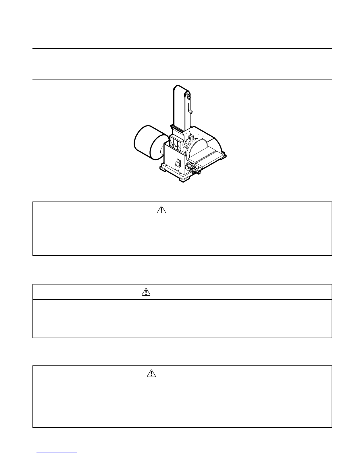
Belt/Disc Sander
Ponceuse à courroie/disque
Lijadora de Correa/Disco
INSTRUCTION MANUAL AND SAFETY INSTRUCTIONS
WARNING
Improper and unsafe use of this power tool can result in death or serious bodily injury!
This manual contains important information about product safety. Please read and understand
this manual before operating the power tool. Please keep this manual available for others
before they use the power tool.
Hitachi Koki
MANUEL D’INSTRUCTIONS ET CONSIGNES DE SÉCURITÉ
AVERTISSEMENT
L’utilisation inadéquate et non sécuritaire de cet outil électrique peut entraîner la mort ou des
blessures graves! Ce manuel contient des informations importantes sur la sécurité. Veuillez
lire et comprendre ce manuel avant d’utiliser l’outil électrique. Veuillez garder ce manuel
disponible pour les autres utilisateurs, avant qu’ils utilisent cet outil électrique.
MANUAL DE INSTRUCCIONES E INSTRUCCIONES DE SEGURIDAD
ADVERTENCIA
¡El uso inadecuado y no seguro de esta herramienta eléctrica puede ocasionar la muerte o
lesiones corporales graves! Este manual contiene información importante sobre la seguridad
del producto. Por favor lea y entienda este manual antes de usar la herramienta eléctrica.
Por favor mantenga disponible este manual para que otros puedan leerlo antes de usar la
herramienta eléctrica.

– 2 –
SECTION Page
Product Specifications..........................................................3
Safety ...................................................................................4
Accessories and Attachments ..............................................7
Carton Contents ...................................................................7
Know Your Sander ................................................................9
SECTION Page
Assembly and Adjustments ................................................10
Operation............................................................................11
Maintenance.......................................................................14
Troubleshooting Guide........................................................15
Parts List.............................................................................45
TABLE OF CONTENTS
HITACHI AUTHORIZED SERVICE CENTERS
Service under this warranty is available from Hitachi Koki U.S.A., Ltd. at:
IN THE U.S.A.
3950 Steve Reynolds Blvd., Norcross, GA 30093
9409 Owensmouth Ave., Chatsworth, CA 91311
OR CALL: (800) 546-1666 for a service center nearest you.
IN CANADA
6395 Kestrel Road, Mississauga, ON L5T 1Z5
OR CALL: (800) 970-2299 for a service center nearest you.
English
SECTION Page
Spécifications du produit ....................................................17
Sécurité ..............................................................................18
Accessoires et équipements...............................................21
Contenu du carton..............................................................21
Connaître sa ponceuse ......................................................23
SECTION Page
Assemblage et ajustements ...............................................24
Fonctionnement..................................................................25
Entretien .............................................................................28
Guide de dépannage..........................................................29
Liste des pièces..................................................................45
TABLE DES MATIÈRES
CENTRES DE SERVICE AUTORISÉS D’HITACHI
Le service en vertu de cette garantie est disponible de Hitachi Koki U.S.A., Ltd,
aux emplacements suivants :
AUX É-U
3950 Steve Reynolds Blvd., Norcross, GA 30093
9409 Owensmouth Ave., Chatsworth, CA 91311
OU APPELER : (800) 546-1666 pour contacter un centre
de service le plus près de votre domicile.
AU CANADA
6395 Kestrel Road, Mississauga, ON L5T 1Z5
OU APPELER : (800) 970-2299 pour contacter un centre
de service le plus près de votre domicile.
Français
SECCION Página
Especificaciones del producto............................................31
Seguridad ...........................................................................32
Accesorios y aditamentos ..................................................35
Contenido de la caja...........................................................35
Conozca su lijadora............................................................37
SECCION Página
Montaje y ajustes................................................................38
Operación...........................................................................39
Mantenimiento....................................................................42
Guía de identificación de problemas ..................................43
Lista de partes....................................................................45
CONTENIDO
CENTROS DE SERVICIO AUTORIZADO DE HITACHI
El servicio de mantenimiento y reparación bajo esta garantía está disponible a través de
Hitachi Koki U.S.A., Ltd. en:
EN EE.UU.
3950 Steve Reynolds Blvd., Norcross, GA 30093
9409 Owensmouth Ave., Chatsworth, CA 91311
O LLAME AL: (800) 546-1666 para averiguar cuál es el
centro de servicio más cercano a usted.
EN CANADA
6395 Kestrel Road, Mississauga, ON L5T 1Z5
O LLAME AL: (800) 970-2299 para averiguar cuál es el
centro de servicio más cercano a usted.
Español

English
– 3 –
PRODUCT SPECIFICATIONS
MOTOR
Power Source...................120 V, AC, 60 Hz,
5.5 AMPS
Belt Speed .......................1850 FPM
(Feet Per Minute)
Disc speed .......................3000 RPM
Horsepower......................1/3 HP (Continuous Duty)
TABLE
Size..................................6 x 9″
Tilt ....................................0 - 45°
DUST COLLECTION................Ye s
BELT AND DISC
Belt size ...........................4″ x 36″
Disc size...........................8″ dia.
NET WEIGHT............................50 LB (22.5 kg)
NOTE: This tool is approved for sanding wood and wood
products only.
To avoid electrical hazards, fire hazards, or damage to the
tool, use proper circuit protection.
Use a separate electrical circuit for your tools.
Your Sander is wired at the factory for 120V operation.
Connect to a 120V, 15 AMP branch circuit and use a 15 Amp
time delay fuse or circuit breaker. To avoid shock or fire,
replace power cord immediately if it is worn, cut or
damaged in any way.
WARNING
Some dust created by power sanding, sawing, grinding, drilling and other construction activities contains chemicals
known to the state of California to cause cancer, birth defects or other reproductive harm. Some examples of these
chemicals are:
• Lead from lead-based paints
• Crystalline silica from bricks, cement and other masonry products
• Arsenic and chromium from chemically treated lumber
Your risk from these exposures varies, depending on how often you do this type of work. To reduce your exposure to
these chemicals, work in a well-ventilated area and work with approved safety equipment such as dust masks that are
specially designed to filter out microscopic particles.
WARNING

GENERAL SAFETY INSTRUCTIONS
BEFORE USING THE SANDER
Safety is a combination of common sense, staying alert and
knowing how to use this Sander.
To avoid mistakes that could cause serious injury, do not
plug the Sander in until you have read and understood the
following:
1. READ and become familiar with the entire Operator’s
Manual. LEARN the tool’s application, limitations and
possible hazards.
2. KEEP GUARDS IN PLACE and in working order.
3. REMOVE ADJUSTING KEYS AND WRENCHES.
Form a habit of checking to see that keys and adjusting
wrenches are removed from the tool before turning ON.
4. KEEP WORK AREA CLEAN. Cluttered areas and
benches invite accidents.
5. DON’T USE IN DANGEROUS ENVIRONMENT. Don’t
use power tools in damp or wet locations, or expose
them to rain. Keep work area well lighted.
6. KEEP CHILDREN AWAY. All visitors should be kept
at a safe distance from work area.
7. MAKE WORKSHOP CHILDPROOF with padlocks,
master switches, or by removing starter keys.
8. DON’T FORCE THE TOOL. It will do the job better and
safer at the rate for which it was designed.
9. USE THE RIGHT TOOL. Do not force tool or attachment
to do a job for which it was not designed.
10. USE PROPER EXTENSION CORD. Make sure your
extension cord is in good condition. When using an
extension cord, be sure to use one heavy enough to
carry the current your product will draw. An undersized
cord will result in a drop in line voltage and in loss of
power that will cause the tool to overheat. The table on
page 6 shows the correct size to use depending on cord
length and nameplate ampere rating. If in doubt, use the
next heavier gauge. The smaller the gauge number, the
heavier the cord.
11. WEAR PROPER APPAREL. Do not wear loose clothing,
gloves, neckties, rings, bracelets, or other jewelry that
may get caught in moving parts. Non-slip footwear is
recommended. Wear protective hair covering to contain
long hair.
12. ALWAYS WEAR EYE PROTECTION. Any Sander can
throw foreign objects into the eyes that could cause
permanent eye damage. ALWAYS wear Safety Goggles
(not glasses) that comply with ANSI Safety Standard
Z87.1. Everyday eyeglasses have only impact-resistance
lenses. They ARE NOT safety glasses. Safety Goggles
are available at HITACHI.
NOTE: Glasses or goggles not in compliance with
ANSI Z87.1 could cause serious injury.
13. WEAR A FACE MASK OR DUST MASK. Sanding
operation produces dust.
14. SECURE WORK. Use clamps or a vise to hold work
when practical. It’s safer than using your hand and it
frees both hands to operate tool.
15. DISCONNECT TOOLS before servicing; when changing
accessories such as blades, bits, cutters, and the like.
16. REDUCE THE RISK OF UNINTENTIONAL STARTING.
Make sure switch is in OFF position before plugging in.
17. USE RECOMMENDED ACCESSORIES. Consult the
Operator’s Manual for recommended accessories. The
use of improper accessories may cause serious injury.
18. NEVER STAND ON TOOL. Serious injury could occur if
the tool is tipped or if the cutting tool is unintentionally
contacted.
19. CHECK FOR DAMAGED PARTS. Before further use of
the tool, a guard or other part that is damaged should
be carefully checked to determine that it will operate
properly and perform its intended function – check for
alignment of moving parts, binding of moving parts,
breakage of parts, mounting, and any other conditions
that may affect its operation. A guard or other part that
is damaged should be properly repaired or replaced.
20. NEVER LEAVE TOOL RUNNING UNATTENDED. TURN
POWER “OFF”. Don’t leave tool until it comes to a
complete stop.
21. DON’T OVERREACH. Keep proper footing and balance
at all times.
22. MAINTAIN TOOLS WITH CARE. Keep tools sharp and
clean for best and safest performance. Follow instructions
for lubricating and changing accessories.
23. DO NOT use power tools in the presence of flammable
liquids or gases.
24.
DO NOT OPERATE the tool if you are under the
influence of any drugs, alcohol or medication that could
affect your ability to use the tool properly.
25. ALWAYS operate the Sander in a well-ventilated area
and provide for proper dust removal. Use dust collection
systems whenever possible. Dust generated from certain
materials can be hazardous to your health.
WARNING
English
– 4 –
SAFETY

SPECIFIC SAFETY INSTRUCTIONS FOR
SANDERS
1. AVOID kickback by sanding in accordance with the
directional arrows.
2. KEEP YOUR HANDS CLEAR of abrasive belt, disc and
all moving parts.
3. FOR optimum performance, do not stall motor or reduce
speed. Do not force the work into the abrasive.
4. ALWAYS support workpiece with table or work stop when
sanding with belt and with table when sanding with disc.
5. NEVER push a sharp corner of the workpiece rapidly
against the belt or disc. Abrasive backing may tear.
6. REPLACE abrasives when they become loaded (glazed)
or frayed.
7. WHENEVER adjusting or replacing any parts on the tool,
turn switch “OFF” and remove the plug from power
source.
8. RECHECK table handle and bolts. They must be
tightened securely.
9. MAKE SURE all guards are properly attached. All guards
should be securely fastened.
10. MAKE SURE all moving parts are free and clear of any
interference.
11. MAKE SURE all fasteners are tight and have not vibrated
loose.
12. WITH power disconnected, test operation by hand for
clearance and adjust if necessary.
13. ALWAYS wear eye protection or face shield.
14. MAKE SURE abrasive belt always tracks properly.
Correct tracking gives optimum performance.
15. AFTER turning switch on, always allow belt and disc to
come up to full speed before sanding or grinding.
16. BE SURE disc turns counterclockwise. Abrasive belt
must travel downward.
ELECTRICAL REQUIREMENTS
POWER SUPPLY AND MOTOR SPECIFICATIONS
To avoid electrical hazards, fire hazards, or damage to the
tool, use proper circuit protection. Use a separate electrical
circuit for your tools. Your sander is wired at the factory for
120V operation. Connect to a 120V, 15 Amp circuit and use a
15 Amp time delay fuse or circuit breaker. To avoid shock or
fire, if power cord is worn or cut, or damaged in any way,
have it replaced immediately.
GROUNDING INSTRUCTIONS
This tool must be grounded while in use to protect the
operator from electrical shock.
IN THE EVENT OF A MALFUNCTION OR BREAKDOWN,
grounding provides a path of least resistance for electric
current and reduces the risk of electric shock. This tool is
equipped with an electric cord that has an equipment-grounding
conductor and a grounding plug. The plug MUST be plugged
into a matching receptacle that is properly installed and
grounded in accordance with ALL local codes and ordinances.
DO NOT MODIFY THE PLUG PROVIDED. If it will not fit the
receptacle, have the proper receptacle installed by a qualified
electrician.
IMPROPER CONNECTION of the equipment-grounding
conductor can result in risk of electric shock. The conductor
with green insulation (with or without yellow stripes) is the
equipment-grounding conductor. If repair or replacement of
the electric cord or plug is necessary, DO NOT connect the
equipment-grounding conductor to a live terminal.
CHECK with a qualified electrician or service person if you
do not completely understand the grounding instructions,
or if you are not sure the tool is properly grounded.
WARNING
WARNING
English
– 5 –

USE ONLY 3-wire extension cords that have 3-prong
grounding plugs and 3-pole receptacles that accept the
tool’s plug. Repair or replace damaged or worn cord
immediately.
Use a separate electrical circuit for your tools. This circuit
must not be less than #12 wire and should be protected with
a 15 Amp time delay fuse. Before connecting the motor to the
power line, make sure the switch is in the OFF position and
the electric current is rated the same as the current stamped
on the motor nameplate. Running at a lower voltage will
damage the motor.
This tool is intended for use on a circuit that has a receptacle
like the one illustrated in Figure A showing a 3-prong
electrical plug and receptacle that has a grounding conductor.
If a properly grounded receptacle is not available, an adapter
(Figure B) can be used to temporarily connect this plug to
a 2-contact ungrounded receptacle. The adapter (Figure B)
has a rigid lug extending from it that MUST be connected
to a permanent earth ground, such as a properly grounded
receptacle box. THE TEMPORARY ADAPTER SHOULD
BE USED ONLY UNTIL A QUALIFIED ELECTRICIAN CAN
INSTALL A PROPERLY GROUNDED OUTLET. The
Canadian Electrical Code prohibits the use of adapters.
CAUTION: In all cases, make certain the receptacle is
properly grounded. If you are not sure, have a qualified
electrician check the receptacle.
This Sander is for indoor use only. Do not expose to rain or
use in damp locations.
GUIDELINES FOR EXTENSION CORDS
USE PROPER EXTENSION CORD. Make sure your extension
cord is in good condition. When using an extension cord,
be sure to use one heavy enough to carry the current your
product will draw. An undersized cord will cause a drop in line
voltage, resulting in loss of power and cause overheating.
The table below shows the correct size to use depending on
cord length and nameplate ampere rating. If in doubt, use
the next heavier gauge. The smaller the gauge number
the heavier the cord.
Be sure your extension cord is properly wired and in good
condition. Always replace a damaged extension cord or have
it repaired by a qualified person before using it. Protect your
extension cords from sharp objects, excessive heat and
damp or wet areas.
MINIMUM GAUGE FOR EXTENSION CORDS (AWG)
(When using 120 Volt only)
Ampere Rating Total length in feet
More Than
Not
More Than
25′ 50′ 100′ 150′
0 6 18 16 16 14
6 10 18 16 14 12
10 12 16 16 14 12
12 16 14 12 Not Applicable
WARNING
English
– 6 –
Properly Grounded
3-Prong Receptacle
Grounding Prong
3-Prong Plug
Grounding Lug
Adapter
3-Prong Plug
Make Sure This
is Connected to
a Known Ground
2-Prong Receptacle
Fig. A
Fig. B

UNPACKING AND CHECKING CONTENTS
Carefully unpack the Sander and all its parts, and compare
against the illustration following. Place the sander on a
secure surface and examine it carefully.
• To avoid injury from unexpected starting, do not plug
the power cord into a power source receptacle during
unpacking and assembly. This cord must remain
unplugged whenever you are assembling or adjusting
the sander.
• Although compact, this sander is heavy. To avoid back
injury, get help whenever you have to lift the sander.
• If any part is missing or damaged, do not plug the band
sander in until the missing or damaged part is replaced,
and assembly is complete.
TABLE OF LOOSE PARTS
ITEM DESCRIPTION QUANTITY
A. Sander 1
B. Table assembly 1
C. Miter gauge assembly 1
D. Dust bag 1
E. Bag clamp 1
F. Abrasive disc 1
G. Long hex wrench 1
H. Hex wrench 1
WARNING
English
– 7 –
ACCESSORIES AND ATTACHMENTS
RECOMMENDED ACCESSORIES
To avoid injury:
• Follow instructions that accompany accessories. Use of
improper accessories may cause hazards.
• Use only accessories designed for this Sander to
avoid injury from thrown broken parts or workpieces.
• Do not use any accessory unless you have completely
read the instruction or operator’s manual for that
accessory.
WARNING
CARTON CONTENTS

English
– 8 –
UNPACKING YOUR SANDER
B
A
C
D
E
F
G
H
English
– 9 –
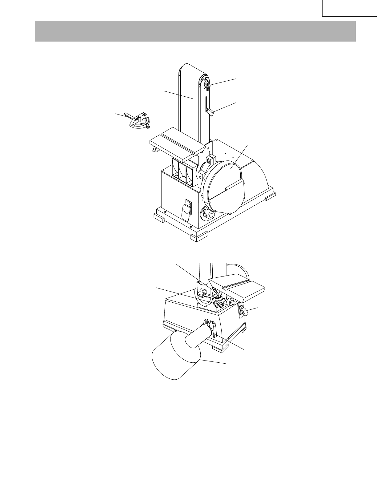
KNOW YOUR SANDER
Abrasive belt
Miter gauge
Angle scale and pointer
Belt tracking mechanism
Belt tension lever
Abrasive disc
ON/OFF Switch
Dust bag clamp
Dust Bag
Table locking knob
ESTIMATED ASSEMBLY TIME 35-50 MINUTES
ASSEMBLY INSTRUCTIONS
For your safety, never connect plug to power source
receptacle until all assembly and adjustment steps are
completed, and you have read and understood the safety
and operating instructions.
MOUNT SANDER
1. Choose a suitable location to mount the sander. The
sander must be installed in a place with ample lighting
and correct power supply. To install sander:
2. The sander must be bolted to a firm, level surface.
3. Make sure there is plenty of room for moving the
workpiece. There must be enough room that neither
operators nor bystanders will have to stand in line with
the wood while using the tool. Allow room so that the
belt assembly can be positioned horizontally.
4. Sander can be installed on a workbench or tool stand
using bolts, lock washers and hex nuts (not supplied).
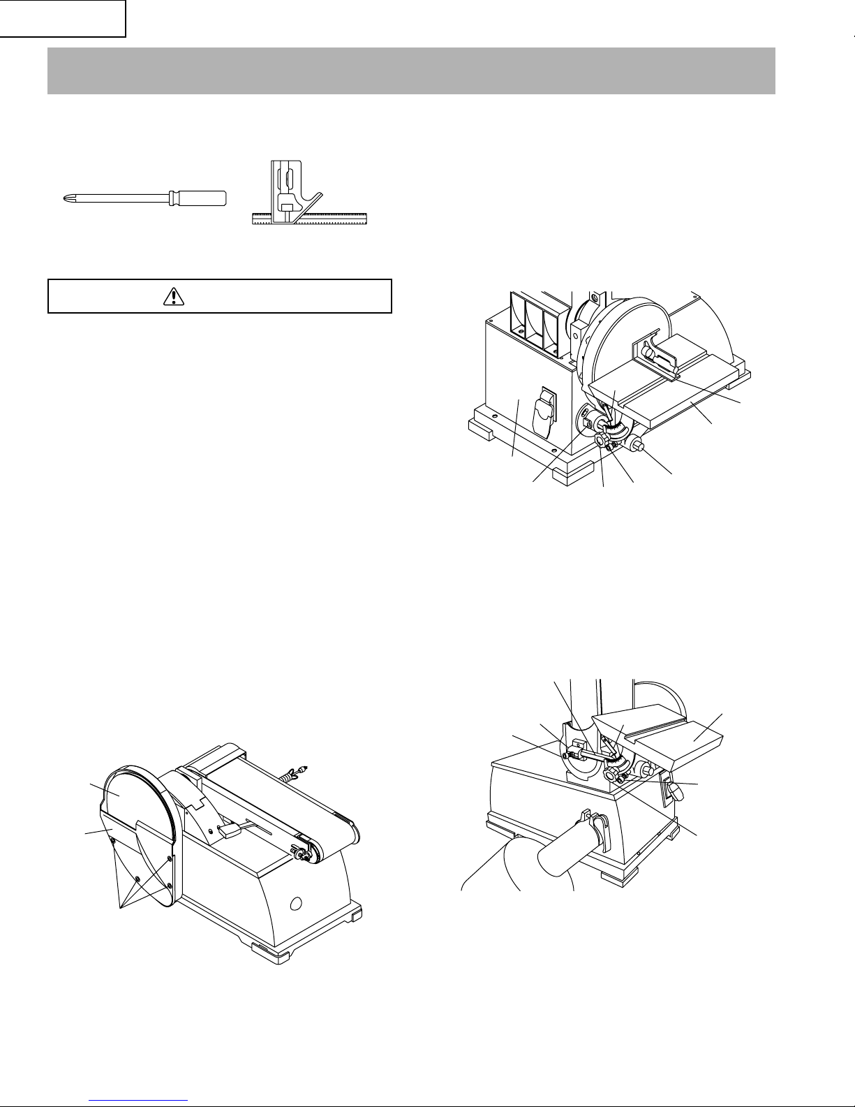
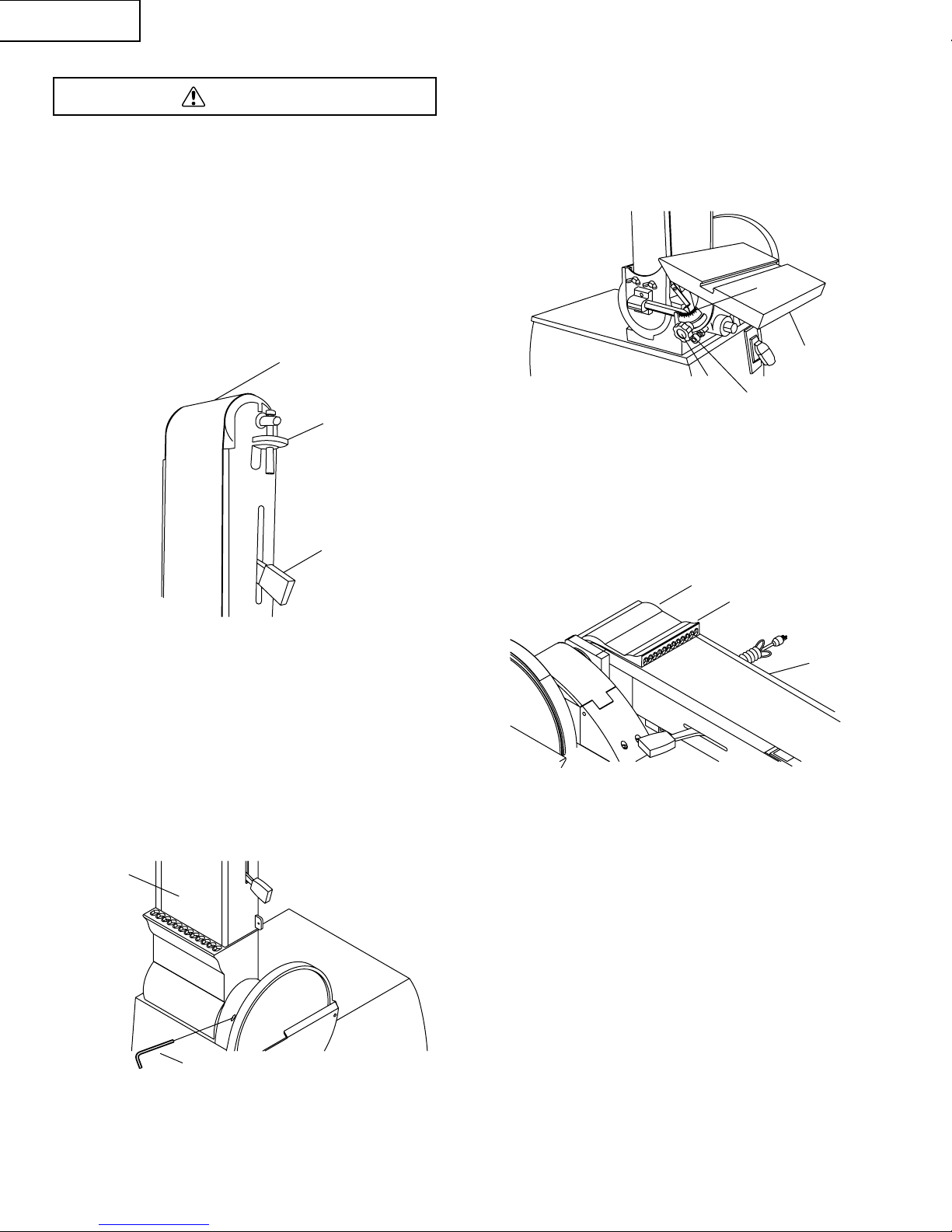
ATTACH ABRASIVE DISC. (Fig. A)
1. Remove disc cover (1) by loosening and removing five
screws (2).
2. Peel protective paper from the back of the abrasive disc
(3)
3. Center the abrasive disc onto the aluminum disc and
press on firmly and evenly.
4. Replace disc cover.
ATTACH TABLE
The included table is used with both the disc and belt.
To use the table with the disc: (Fig. B)
1. Insert support rod (1) into base (2). Secure with bolt (3)
on flat surface of rod.
2. Position table assembly (4) on rod. Make sure gap
between table and disc is 1/16″ or less. Secure with
bolt (5).
3. Using a combination square (6), set the table perpendicular to the disc, and secure in position with knob (7).
If necessary, set pointer (8) at 0.
To use the table with the belt (Fig C)
1. Insert support rod (1) into bracket (2). Secure with bolt
(3) on flat surface of rod.
2. Position table assembly (4) on rod. Make sure gap
between table and belt is 1/16″ or less. Secure with
bolt (5)
3. Using a combination square, set the table perpendicular
to the belt and secure in position with knob (6).
If necessary, set pointer (7) at 0.
WARNING
English
– 10 –
ASSEMBLY AND ADJUSTMENTS
Phillips Screwdriver Combination Square
Fig. A
2
1
Fig. B
Fig. C
3
1
2
1
2
3
7
5
4
6
8
7
6
5
4
3
English
– 11 –
BASIC SANDER OPERATIONS
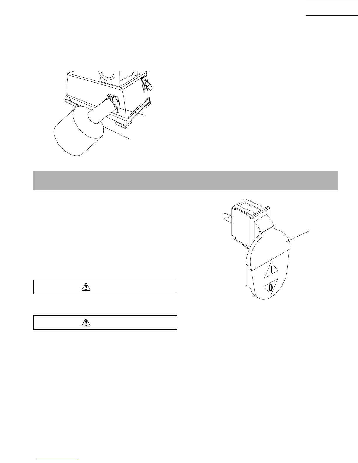
ON/OFF Switch (Fig. E)
The keyed switch is intended to prevent unauthorized use
of the sander.
1. To turn the sander ON (I) insert the yellow key (1) into
the key slot in the center of the switch.
2. Push the key firmly into the slot, then push switch to
the ON (I) position to start the sander.
3. To turn the sander OFF (O) push the switch to the
down position.
4. Remove the yellow switch key, when the sander has
come to a complete stop, by gently pulling it outward.
Remove the switch key whenever the sander is not in use.
Place it in a safe place and out of reach of children.
ALWAYS lock the switch OFF when the sander is not in use.
Remove the key and keep it in a safe place. In the event of
power failure, blown fuse, or tripped circuit breaker, turn
the switch OFF and remove the key, preventing accidental
startup when power comes on.
WARNING
WARNING
Fig. E
1
Fig. D
1
OPERATION
ATTACH DUST COLLECTION BAG (Fig. D)
1. Place clamp (1) over bag sleeve (2).
2. Slide sleeve with clamp over the dust port.
3. Secure in position by tightening clamp handle. Do
not force handle. Rotate the handle to increase the
clamp size.
2
ADJUSTING BELT TRACKING (Fig. F)
Keep hands away from idler drum while adjusting belt
tracking.
1. Make sure tension lever (2) is tight (toward drive drum).
2. Quickly turn the switch ON and OFF to check the
tracking. Belt (1) should ride centered on idler and drive
drums. Adjust tracking nut (3) as needed to center belt
on drums.
3. If belt moves to the left, turn tracking nut to the right.
If belt moves to the right, turn tracking nut to the left.
4. Quickly turn switch ON and OFF again. If belt moves to
one side, continue adjusting tracking nut as needed
to center belt on drums.
ADJUSTING BELT ASSEMBLY POSITION (Fig. G)
Sanding belt assembly (1) can be adjusted from vertical
to horizontal position, or any angle in between.
1. Loosen socket head bolt that is threaded into pivot
bracket.
2. Tilt belt assembly to desired position. Secure belt
assembly position by tightening socket head bolt in
pivot bracket.
3. Adjustable positive stops are provided for both horizontal
and vertical positions.
NOTE: The horizontal limit stop is located on top of the base.
ADJUSTING TABLE ANGLE (Fig. H)
Table tilts from 0 o 45
° and will be within +/-3°.
1. To adjust table angle, loosen handle (1), tilt table (2) to
desired angle on scale (3) then secure by tightening
handle.
2. Make sure the gap between table and belt is 1/16″ or
less. If necessary, loosen bolt (4) and reposition table.
Secure with bolt.
HORIZONTAL BELT SANDING WITH WORK STOP (Fig. I)
1. Remove table from belt assembly (1).
2. Tilt belt assembly from vertical to horizontal position
and secure in position.
3. Work stop (2) has been integrated into dust shroud (3).
4. Idler drum can be used as a contact drum to sand
surfaces.
CAUTION
English
– 12 –
Fig. F
3
1
2
Fig. H
2
4
1
3
Fig. G
1
2
Fig. I
1
2
3
English
– 13 –
ABRASIVE BELT SANDING
1. Finishing flat surfaces: Hold workplace firmly with both
hands; keep fingers away from abrasive belt. Use table to
position and secure work being sanded. Keep end butted
against table and move work evenly across abrasive belt.
2. Finishing long pieces: Use belt in horizontal position with
work stop. Apply only enough pressure to allow abrasive
belt to remove material.
Use work stop to position and secure work being sanded.
Keep end butted against work stop and move work
evenly across abrasive belt. Use extra caution when
finishing very thin pieces.
3. Finishing curved edges: Finish outside curves on flat
portion or abrasive belt. Finish inside curves on idler
drum portion of abrasive belt.
4. Finishing end grain: It is more convenient to finish ends
of long workpieces with the abrasive belt in a vertical
position.
Position table on belt side of sander. Move work evenly
across abrasive belt. For accuracy, use miter gauge.
Table may be tilted for beveled work.
ABRASIVE DISC SANDING
1. Abrasive disc sanding is well suited for finishing small flat
surfaces and convex edges.
2. Move workpiece across down side (left) of abrasive disc.
Hold workpiece firmly with both hands; keep fingers away
from abrasive disc.
3. Abrasive disc moves faster and removes more material at
outer edge.
4. For accuracy, use miter gauge.
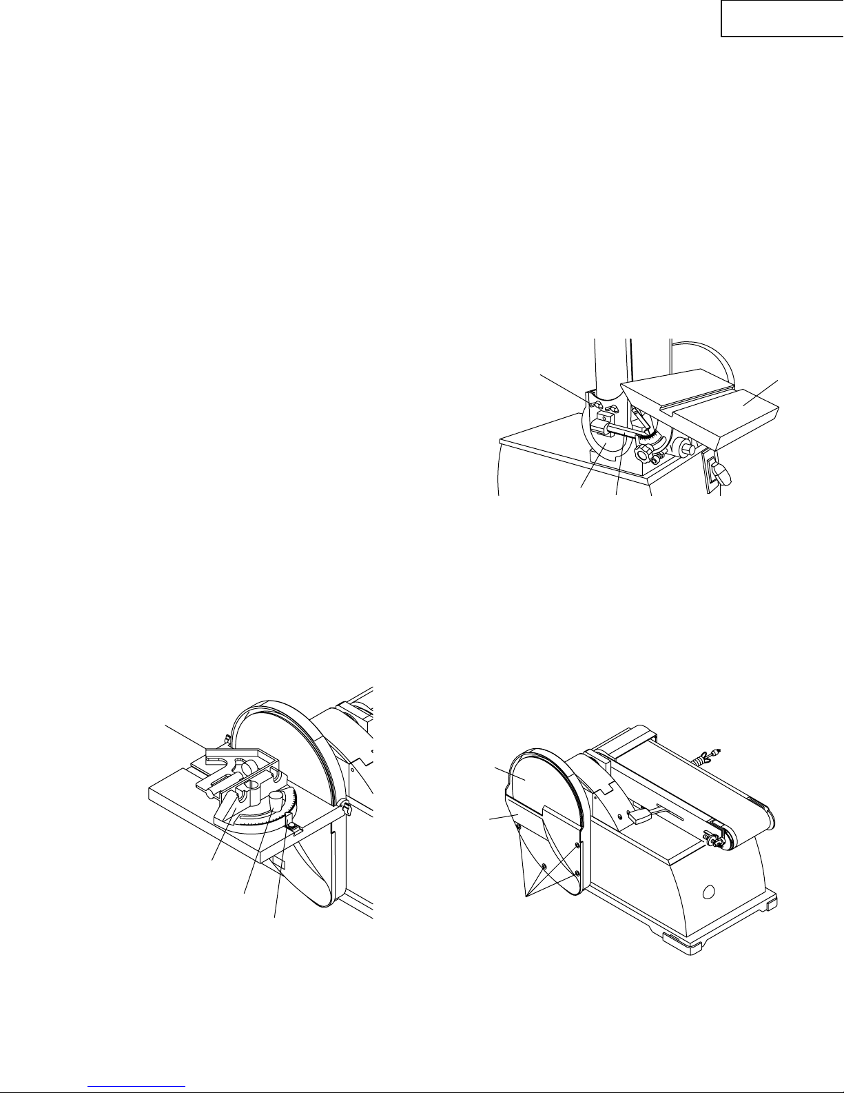
USING MITER GAUGE (Fig. J)
1. Use miter gauge (1) for securing the work and holding
the proper angle while standing.
2. Use a combination square (4) to adjust miter gauge
square to belt (disc). Pointer (2) should be at zero.
Loosen screw and reposition pointer if necessary.
3. After setting miter gauge square to belt (disc), adjust to
desired angle by repositioning the miter gauge scale
and locking it into place with knob (3).
REPLACING ABRASIVE BELT (Fig. K)
1. Sanding belt should be replaced when worn, torn,
or glazed.
2. Remove table assembly (1) and support rod (2).
3. Loosen and remove wing screws and washers (3)
and cover (4)
4. Release belt tension by pushing tension lever up toward
idler drum. Slide old belt off the drive and idler drums.
NOTE: There may be an arrow on the inside of the belt. The
arrow should point in the direction of belt travel to ensure
that the splice in the belt will not come apart.
5. Slide new belt over the drive and idler drums; center
belt on drums.
6. Push tension lever down towards drive drum to tension
belt.
7. Check tracking. See “Adjusting Belt Tracking”, on page 12.
8. Assemble in reverse order.
REPLACING ABRASIVE DISC (Fig. L)
1. Remove table assembly.
2. Remove disc cover (1) by loosening and removing
four screws (2).
3. Remove old abrasive disc by peeling it from the
aluminum disc. Removng aluminum disc is not
necessary.
4. Clean aluminum disc (3) if necessary. Use mineral spirits
to remove old adhesive residue. Select the desired
abrasive disc and apply to aluminum disc.
5. Replace disc cover.
Fig. K
1
2
4
Fig. L
3
1
3
2
Fig. J
1
3
2
4

GENERAL MAINTENANCE
• For you own safety, turn switch OFF and remove the
plug from power source receptacle before maintaining,
cleaning, adjusting, or lubricating your sander.
• To avoid fire or toxic reaction, never use gasoline,
naphtha, acetone, lacquer thinner or similar highly
volatile solvents to clean the sander.
• To avoid eye injury from blowing debris, wear safety
goggles when blowing out sawdust.
CLEANING
Keep machine and workshop clean. Do not allow sawdust to
accumulate on the tool. Keep the drums clean. Dirt on drums
will cause poor tracking and belt slippage. Periodically empty
the dust collection bag.
Be certain motor is kept clean and is frequently vacuumed
free of dust.
Use soap and water to clean painted parts, rubber parts
and plastic guards.
LUBRICATION
The shielded ball bearings in this tool are permanently
lubricated at the factory. They require no further lubrication.
• When operation seems stiff, a light coat of paste wax
applied to the table will make it easier to feed the work
while finishing.
• Do not apply wax to the belt platen. Belt could pick up
wax and deposit it on wheels causing belt to slip.
KEEP TOOL IN REPAIR
• If power cord is worn, cut, or damaged in any way, have
it replaced immediately.
• Replace worn abrasives when needed.
• Replace any damaged or missing parts. Use parts list
to order parts.
WARNING
English
– 14 –
MAINTENANCE

English
– 15 –
• To avoid injury from an accidental start, turn the switch OFF and remove the plug from the power source before making
any adjustments.
• All electrical or mechanical repairs should be done only by qualified service technicians. Contact Hitachi Authorized
Service Center.
GENERAL
TROUBLESHOOTING GUIDE
PROBABLE CAUSE
1. Low Voltage.
2. Open circuit in motor or loose
connections.
3. Defective switch.
4. Defective capacitor.
1. Short circuit in line cord or plug.
2. Short circuit in motor or loose
connections.
3. Incorrect fuses or circuit breakers
in power line.
1. Power line overloaded with lights,
appliances and other motors.
2. Undersize wires or circuits too long.
3. General overload of power company’s
facilities.
Motor overloaded.
1. Short Circuit in motor or loose
connections.
2. Low voltage.
3. Incorrect fuses or circuit breakers
in power line.
4. Motor overload.
1. Applying too much pressure to
workpiece.
2. Not enough tension on V-Belt.
Not tracking properly.
1. Dust collection bag full.
2. Belt loose or broken.
3. Impeller loose or broken.
PROBLEM
Motor will not start.
Motor will not start;
fuses blown or circuit
breakers are tripped.
Motor fails to develop full
power (power output of
motor decreases rapidly
with decrease in voltage
at motor terminals).
Motor overheats.
Motor stalls (resulting in
blown fuses or tripped
circuit breakers).
Machine slows down
while operating.
Abrasive belt runs off
top wheel.
Dust collection not working.
REMEDY
1. Check power line for proper voltage.
2. Inspect all lead connections on motor for loose or
open connection.
3. Replace switch.
4. Replace capacitor.
1. Inspect line cord or plug for damaged insulation
and shorted wires.
2. Inspect all lead connections on motor for loose or
shorted terminals or worn insulation on wires.
3. Install correct fuses or circuit breakers.
1. Reduce the load on the power line.
2. Increase wire sizes, or reduce length of wiring.
3. Request a voltage check from the power company.
Reduce load on motor.
1. Inspect connections in motor for loose or shorted
terminals or worn insulation on lead wires.
2. Correct the low line voltage conditions.
3. Install correct fuses or circuit breakers.
4. Reduce load on motor.
1. Ease up on pressure.
2. Increase tension on V-Belt. See Schematic A,
turn bolt ref. 0032 clockwise.
See operation “Adjusting Belt Tracking”.
1. Empty dust collection bag.
2. Replace belt.
3. Replace impeller.
WARNING
 Loading...