

Page 1
TABLE
SAFETY DURING REPAIR WORK ……………………………………
1
SPECIFICATION …………………………………………………
2
MAIN PARTS COMPONENTS ………………………………………
2
BASIC OPERATION..................................................................................
3
RESISTANCE VALUE ..................................................................................
4
ERROR CODE ..................................................................................
5
CIRCUIT DIAGRAM ………………………………………………
6
FIGURE PARTS. ……………………………………………..
7-9
PARTS LIST
MODEL : R-Z660ERU9X (STS) ……………………………………..
10-13
SPECIFICATIONS
TYPEDOUBLE DOOR
MODEL
POWER SOURCE 1Ø,220-240V, 50Hz
POWER INPUT (W)
TOTAL CURRENT (A)
NET550L
GROSS601L
W845
D733
H1810
NET WEIGHT ( Kgs )89
R-Z660ERU9X (STS)
REFRIGERATOR
H.C.P.T.
NO. 2109E
SERVICE MANUAL
DIMENSIONS
(mm)
JAN '11
R-Z660ERU9X
107
0.6
VOLUME
PT
NO. 2109E
R-Z660ERU9X (STS)
Page 2
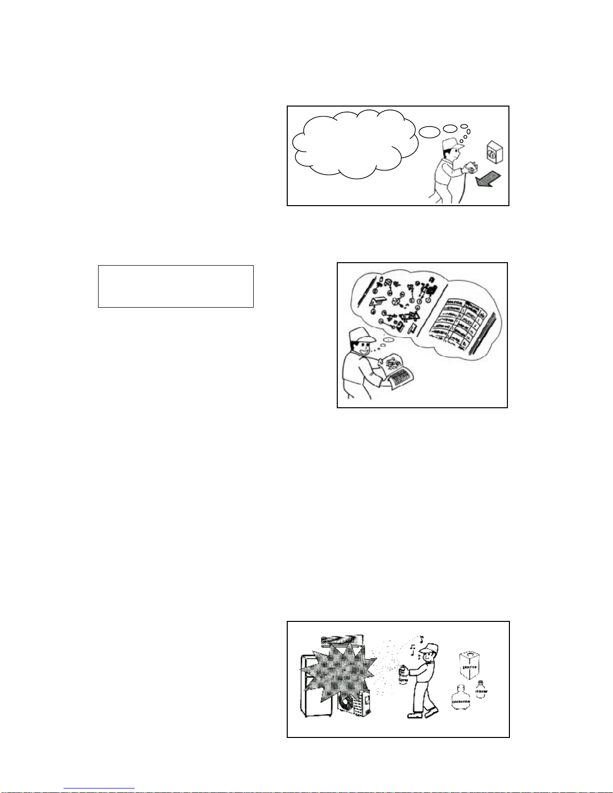
1.
In order to disassemble and repair the
unit in question, be sure to disconnect
the power cord plug from the power
outlet before starting the work.
2.
If it is necessary to replace any parts, they should be replaced with respective genuine parts for the unit, and the
replacement must be effected in correct manner according to the instructions in the Service Manual of the unit.
3.
After completion of repairs, the initial state should be restored.
4.
Lead wires should be connected and laid as in the initial state.
5.
Modification of the unit by the user himself should absolutely be
prohibited.
6.
Tools and measuring instruments for use in repairs or inspection should be accurately calibrated in advance.
7.
In installing the unit having been repaired, be careful to prevent the occurrence of any accident such as electrical
shock, leak of current, or bodily injury due to the drop of any part.
8.
To check the insulation of the unit, measure the insulation resistance between the power cord plug and grounding
terminal of the unit.
The insulation resistance should be 1M
Ω
or more as measured by a 500V DC megger.
9.
The initial location of installation such as window, floor or the other should be checked for being safe enough to
support the repaired unit again.
If it is found not so strong and safe, the unit should be installed at the initial location after reinforced or at a new location.
10.
Any inflammable object must not be placed
about the location of installation.
11.
Check the grounding to see whether it is proper
or not, and if it is found improper, connect the
grounding terminal to the earth.
SAFETY DURING REPAIR WORK
First, I must disconnect
the power cord plug
from the power outlet.
If the contacts of electrical parts are
defective, replace the electrical parts
without trying to repair them.
DANGER
1
Page 3
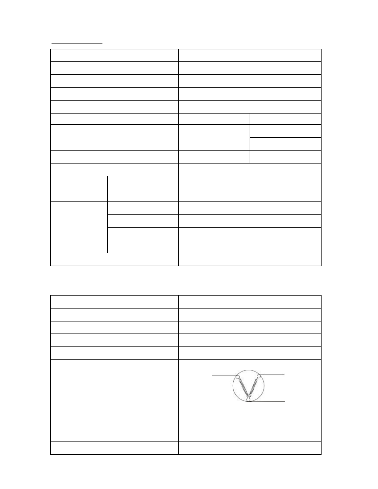
S P E C I F I C A T I O N
MODEL
COMPRESSORPTR-Z660EMX 018 (FL15S68NAD)
STARTING DEVICEPTR-Z481EMS 003 (PGN6SBT)
OVERLOAD RELAYPTR-Z481EMS 002 (P1.6C37A1)
RUNNING CAPACITORPTR-480ET5 005 (4μF/400V)
FREEZER SENSOR
R (21°C) = 12 k Ω ± 3 %
R (25°C) = 10 k Ω ± 2 %
REFRIGERATOR SENSORR (0°C) = 6.35 k Ω ± 2 %
REFRIGERATOR CHARGING R-134a (kg)0.165 kg
TEMPERATURE FRESH FOODELECTRONIC CONTROL
CONTROL FREEZERELECTRONIC CONTROL
DEFROSTING WAYHEATER
DEFROSTING INITIATIONF:AUTOMATIC , R:AUTOMATIC
SYSTEM TERMINATIONF:AUTOMATIC , R:AUTOMATIC
EVAPORATIONFORCED
FREEZER * * * *
MAIN PARTS COMPONENTS
COMPRESSOR
PHASE
RATE VOLTAGE ( V )
RATE FREQUENCY ( Hz )
POLE NUMBER
CONNECTION
M - C = 16.5 Ω
S - C = 23.9 Ω
STARTING CURRENT (A)7.91 A
RESISTANCE VALUE 75°C
PTR-Z660EMX 018 (FL15S68NAD)
SINGLE PHASE
220-240V
50Hz
2
PTR-W720FMX 071
YES
R-Z660ERU9X
UP HINGE SENSORPTR-Z400V 050
PTR-W720FMX 065R (-20°C) = 18.9k Ω ±2%
MAIN COIL
STARTING COIL
MS
C
2
Page 4
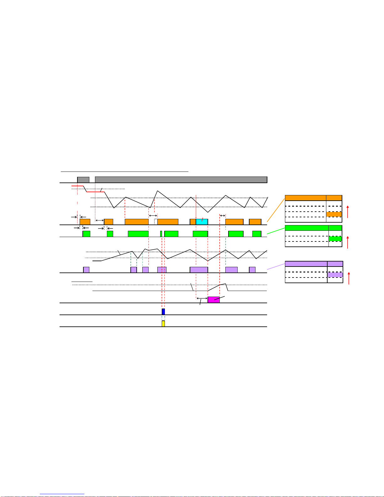
3
●Comp.
●Power
supply
●R-Room
Temp.
●F-Room
Temp.
●R-Fan
●Damper
●Evaporator
Temp.
●Defrost
heater
●R-Lamp
-8℃
High temp.(-16℃)
Low temp.(-22℃)
On
F-sensor
High temp.(4℃)
Low temp.(2℃)
R-sensor
On
Open
Open
On
●R-Door
(R-Door sw)
8.5℃
D-sensor
On
On
~~~~~~~~~
Off-time
10min
~~
t1t2t3t4
Pre-Cool
Off-time
10min
Pre-Cool time≦30min
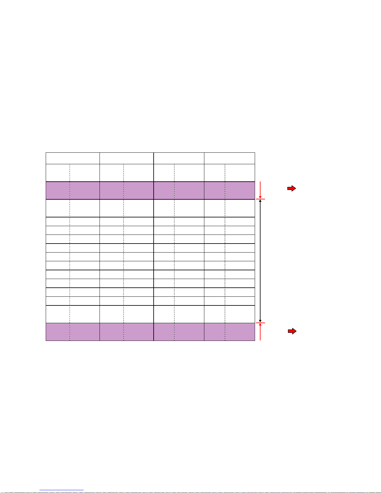
Basic operation(time chart) of 508L-550L REF.
Comp. On-time:
t1+t2+t3+t4+…≧12h
High
Priority
High
Priority
ConditionComp.
Off-timeOff
DefrostingOff
F-sensor≧High temp.
On
F-sensor≦Low temp.Off
ConditionDamper
Comp. offClose
R-sensor≧High temp.Open
R-sensor≦Low temp.Close
ConditionR-Fan
R-Door openOff
Comp. onOn
Comp. offOff
Off-time
10min
High
Priority
Defrosting
30s30s
25s
26°C
Page 5
4
Temp.ResistanceTemp.ResistanceTemp.ResistanceTemp.Resistance
(℃)(Ω)(
℃
)(Ω)(
℃
)(Ω)(
℃
)(Ω)
~~~~~~~~
-57241.87k-2019.23k-58271.14k-20105.38k
~~~~~~~~
-2525.58k-1514.26k-2019.17k-1582.03k
-2018.9k-1010.78k-1010.83k-1060.86k
-1514.13k-58.23k-58.27k-545.67k
-1010.68k06.35k06.38k034.62k
-58.15k54.94k54.97k526.52k
06.29k103.88k103.90k1020.50k
54.90k153.08k153.09k1515.99k
103.85k202.46k202.47k2012.00k
153.05k251.98k251.98k259.97k
202.43k301.60k301.61k307.97k
251.96k351.31k401.08k356.42k
301.59k401.07k500.74k405.20k
~~~~~~~~
610.51k600.51k610.50k622.32k
~~~~~~~~
TC-sensorF-sensorR-sensorD-sensor
Normal
range
Abnormal
range
Abnormal
range
Display
Error code
Display
Error code
Page 6

Priority
sequence
Error code
(LED on PCB)
Breakdown
list
Breakdown
description
Operation
11s ON + Blink onceF-sensor abnormalF-sensor value abnormalProvisional mode
21s ON + Blink twiceR-sensor abnormalR-sensor value abnormalProvisional mode
31s ON + Blink 3 timesTC-sensor abnormalTC-sensor value abnormalDisplay error code
41s ON + Blink 4 timesD-sensor abnormalD-sensor value abnormalNo defrosting
5Blink twice
EEPROM data
abnormal
EEPROM data
abnormal
Display error code
6Blink 12 times
R-Fan motor abnormal
or 12V drops
R-Fan motor abnormal
or 12V drops
R-Fan motor stops and retry after 3min.
7Blink 4 times
Defrosting circuit
abnormal
Defrosting continues
even after 2 hours
After 2 hours,stop defrosting
and display error code
83s ON + Blink onceFreezer not cool
F-sensor stays over -10℃
for 72 hours
Display error code
93s ON + Blink twiceRefrigerator not cool
R-sensor stays over 10℃
for 72 hours
Display error code
5
Page 7

CIRCUIT DIAGRAM MODEL : R-Z660ERU9X
6
Page 8

1
9
1
1
2
2
3
3
4
6
4
4
4
5
6
87910131211
15
14
161720211822222
3
7
Page 9

26
25
7980818282838485868778777
6
31
24
29
30
28
27
4847495051525
3
54
55
565758646566686769707
1
32
33
35
36
37
38
39
40
40
42
41
41
34
34
34
72
74
45
73
75
59
60
61
62
63
63
79
46
44
43
45
8
Page 10

114
9
Page 11

MODEL : R-Z660ERU9X (STS)
Q'TY/SET
R-Z660ERU9X
1PTR-Z660EM 001SCREW 3x122
2PTR-Z660EMX 002HANDLE-LOCK (SLS,STS)2
3PTR-Z660EMX 003HANDLE-UP-LO (SLS,STS)2
4PTR-Z530AUN7KX 001SCREW8
5PTR-Z660EMX 004HANDLE-PIPE-F (SLS,STS)1
6PTR-Z660EMX 005HANDLE-C (SLS,STS)2
7PTR-Z470AK6K 006DOOR-BADGE1
8PTR-Z660EMX 006DOOR-PANEL-F (STS)1**
9PTR-S31NVH 111
DOOR-CLOSER (STS,W,A,SS,GGR,RO,S,
SU,GR,SLS,SLK,TGL,WGR,ST)
1
10PTR-N39WS 104DOOR-STOPPER-R (95°)1
11PTR-Z700AM 006DOOR-GASKET-F '071**
12PTR-Z660EMX 007DOOR-PANEL-F-ASS'Y (STS)1**
13PTR-Z700AM 001DOOR-BASKET-F2
14PTR-Z70FGD9X 001HANDLE-PIPE-R (SLS,STS)1
15PTR-Z70FGD9X 002DOOR-PANEL-R (STS)1**
16PTR-578AMX 005D-STOPPER-R (STS,SS)1
17PTR-Z700AM 007DOOR-GASKET-R '071**
18PTR-Z70FGD9X 003DOOR-PANEL-R-ASS'Y (STS)1**
19PTR-610AS3T 013EGG-CASE-5501
20PTR-Z700AM 002DOOR-BASKET-R11
21PTR-Z700AM 003DOOR-BASKET-R21
22PTR-Z700AM 004DOOR-POCKET2
23PTR-Z700AM 005DOOR-BASKER-R3 '071
24PTR-W720EM 002ICE-CORNER1
25PTR-610AS3T 021ICE-MAKER-SPRING2
26PTR-610AS3T 020ICE-TRAY2
27PTR-W720EM 003ICE-SUPPORT1
28PTR-610AS3T 023ICE-BOX-5501
29PTR-Z700AM 012STOPPER-CHILL-CASE '071
30PTR-Z660AG7 003SCREW 4x161
REMARKSNO.SERVICE NO.SERVICE NAME
** : RELATED PART FOR COOLING SYSTEM
10
Page 12

MODEL : R-Z660ERU9X (STS)
Q'TY/SET
R-Z660ERU9X
31PTR-W720FMX 056GLASS-SHELF-F1
32PTR-Z700AM 013CHILLER-CASE '071
33PTR-Z700AM 014CHILLER-DOOR '071
34PTR-Z630AM 019GLA-SHELF-R3
35PTR-Z700AM 015R-VEGETABLE-GLASS-SHELF '071
36PTR-Z700AM 016R-VEGETABLE-GLASS-GASKET '071
37PTR-Z700AM 017CRISPER-GASKET '071
38PTR-Z610EUK9K 011CRISPER-ASS'Y1
39PTR-Z700AM 019SEPARATE-550 '071
40PTR-Z675AS7KV 005ROLLER-PIN2
41PTR-Z675AS7KV 004ROLLER2
42PTR-Z660ERU 001INSTRUCTION-BOOK1
43PTR-Z660EUN9KX 001FREEZER-DUCT-ASS'Y1**
44PTR-Z610EMX 013LAMP-SOCKET1
45PTR-600ET3X 016LAMP2
46PTR-W720FMX 059LAMP-COVER-F1
47PTR-Z400V 030D-SENSOR1**
48PTR-208A1HE 010SENSOR HOLDER1
49PTR-W660ES9V 004EVAPORATOR1**
50PTR-Z530AUN7KX 003FUSE1**
51PTR-W720FMX 065F-SENSOR1**
52PTR-W720FMX 064R-MOTOR1**
53PTR-W720FMX 063M-PLATE1
54PTR-Z710EMX 002FAN-GUARD1**
55PTR-W690FMX 015F-GRILL1
56PTR-W720FMX 067HEATER-COVER1
57PTR-W720FMX 068R-HEATER1**
58PTR-W900FJ6X 009HEATER COVER1
59PTR-Z660EMX 012CONTROL-PANEL-ASS'Y1**
60PTR-Z400V 043PCB-PANEL-395L-DX1**
REMARKSNO.SERVICE NO.SERVICE NAME
** : RELATED PART FOR COOLING SYSTEM
11
Page 13
MODEL : R-Z660ERU9X (STS)
Q'TY/SET
R-Z660ERU9X
61PTR-Z400V 044C-PANEL-DX1
62PTR-Z400V 045STICKER-CP-DX-NW-091
63PTR-Z400V 046TEMP-CTL-DIAL2
64PTR-610AS3XT 015STICKER C-F-PLT '03 (STS)1
65PTR-Z410AM-1 004LEFT-CHILLER-DOOR-BUSH '071
66PTR-Z410AM-1 005RIGHT-CHILLER-DOOR-BUSH '071
67PTR-W720FMX 076R-DUCT-COVER1
68PTR-W720FMX 074DAMPER-CORD1**
69PTR-W720FMX 075DAMPER 1**
70PTR-W720FMX 073RF-PAD1
71PTR-W720FMX 072R-PANEL1
72PTR-W720FMX 071R-SENSOR1**
73PTR-W720FMX 099LAMP-SOCKET1**
74PTR-W720FMX 070LAMP-COVER-R1
75PTR-Z570EU9 003ALUMINIUM-PANEL1
76PTR-Z700AM 028LO-FRONT-COVER '07 (STS,SLS)1
77PTR-610AS3T 069ADJUSTOR1
78PTR-Z550AM 029LEG-475-EDP1
79PTR-W660FU9X 003SCREW M5x204
80PTR-Z660AG7XD 007LO-HINGE-550L '071
81PTR-400WP 038ADJUSTER-L1
82PTR-Z660AGS6D 003SCREW4
83PTR-400WP 042BACK-HANDLE-L1
84PTR-400WP 041BACK-HANDLE-R1
85PTR-Z660EMX 013UP-HINGE-COVER-R1
86PTR-Z400V 050TC-SENSOR1**
87PTR-N39WS 061HEX-BOLT (UP HING)3
88PTR-W720FMX 081UP-HINGE-R1
89PTR-25A3P 022DOOR SWITCH2**
90PTR-Z700AM 029CENTER-HINGE '071
REMARKSNO.SERVICE NO.SERVICE NAME
** : RELATED PART FOR COOLING SYSTEM
12
Page 14

MODEL : R-Z660ERU9X (STS)
Q'TY/SET
R-Z660ERU9X
91PTR-Z70FGD9X 009PLUG-CORD1**
92PTR-Z660EMX 014PCB-CASE1
93PTR-Z660EMX 017PCB-MAIN1**
94PTR-480ET5 005CAPACITOR1**
95PTR-Z660EU9 002PCB-COVER1
96PTR-208A1HE 012HOLE PLUG1
97PTR-Z610EG9 002CORD-CASE1
98PTR-44A4P 009EVAPORATOR PAN1
99PTR-14MX7 008DRYER KMP (NON-CFC)1**
100PTR-610AS3T 083DRYER BUSH1
101PTR-Z660EMX 018COMPRESSOR1**
102PTR-Z481EMS 002OVERLOAD1**
103PTR-60NSD 016H-COVER-F41
104PTR-Z481EMS 003STARTING DEVICE1**
105PTR-Z675ES9 001COMPRESSOR BASE1
106PTR-SF37WVPTH 006ROLLER2
107PTR-923V 061ROLLER PIN2
108PTR-Z610ARP7 003UP-CARTON550 '081
109PTR-Z700AM 032UP-CUSHION '071
110PTR-Z66ARP7 003SIDE CUSHION2
111PTR-Z66ARP7 006FRONT-CUSHION1
112PTR-Z660ERU 002CARTON-BOX-R-Z660ERU9X (STS)1
113PTR-610AS3T 090POLY BAG1
114PTR-Z700AM 034CARTON-BASE '071
REMARKSNO.SERVICE NO.SERVICE NAME
** : RELATED PART FOR COOLING SYSTEM
13
 Loading...