

Hitachi R-Z570ERU9X, R-Z570ERU9XSTS Service Manual
TABLE
SAFETY DURING REPAIR WORK ……………………………………
1
SPECIFICATION …………………………………………………
2
MAIN PARTS COMPONENTS ………………………………………
2
BASIC OPERATION..................................................................................
3
RESISTANCE VALUE ..................................................................................
4
ERROR CODE ..................................................................................
5
CIRCUIT DIAGRAM ………………………………………………
6
FIGURE PARTS. ……………………………………………..
7-9
PARTS LIST
MODEL : R-Z570ERU9X (STS) ……………………………………..
10-13
SPECIFICATIONS
TYPEDOUBLE DOOR
MODEL
POWER SOURCE 1Ø,220-240V,50Hz
POWER INPUT ( W )
TOTAL CURRENT ( A )
NET475L
GROSS531L
W740
D736
H1795
NET WEIGHT ( Kgs )81
R-Z570ERU9X (STS)
REFRIGERATOR
H.C.P.T.
NO. 2103E
SERVICE MANUAL
DIMENSIONS
(mm)
JAN '11
R-Z570ERU9X
106
0.6
VOLUME
PT
NO. 2103E
R-Z570ERU9X (STS)
HITACHI

1.
In order to disassemble and repair the
unit in question, be sure to disconnect
the power cord plug from the power
outlet before starting the work.
2.
If it is necessary to replace any parts, they should be replaced with respective genuine parts for the unit, and the
replacement must be effected in correct manner according to the instructions in the Service Manual of the unit.
3.
After completion of repairs, the initial state should be restored.
4.
Lead wires should be connected and laid as in the initial state.
5.
Modification of the unit by the user himself should absolutely be
prohibited.
6.
Tools and measuring instruments for use in repairs or inspection should be accurately calibrated in advance.
7.
In installing the unit having been repaired, be careful to prevent the occurrence of any accident such as electrical
shock, leak of current, or bodily injury due to the drop of any part.
8.
To check the insulation of the unit, measure the insulation resistance between the power cord plug and grounding
terminal of the unit.
The insulation resistance should be
1
MΩ or more as measured by a
500
V DC megger
.9.The initial location of installation such as window, floor or the other should be checked for being safe enough to
support the repaired unit again.
If it is found not so strong and safe, the unit should be installed at the initial location after reinforced or at a new location.
10.
Any inflammable object must not be placed
about the location of installation.
11.
Check the grounding to see whether it is proper
or not, and if it is found improper, connect the
grounding terminal to the earth.
SAFETY DURING REPAIR WORK
First, I must disconnect
the power cord plug
from the power outlet.
If the contacts of electrical parts are
defective, replace the electrical parts
without trying to repair them.
DANGER
1
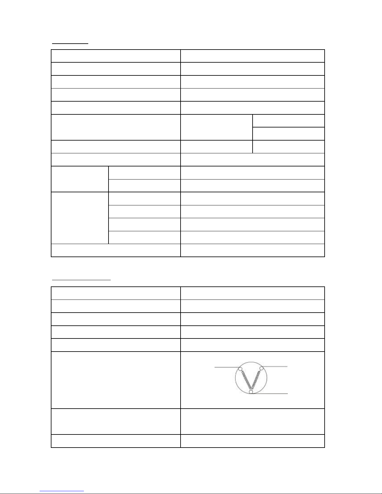
SPECIFICATION
MODEL
COMPRESSORPTR-Z660EMX 018 (FL15S68NAD)
STARTING DEVICEPTR-Z481EMS 003 (PGN6SBT)
OVERLOAD RELAYPTR-Z481EMS 002 (P1.6C37A1)
RUNNING CAPACITORYES
R (21°C) = 12 k Ω ± 3 %
R (25°C) = 10 k Ω ± 2 %
REFRIGERATOR SENSORR (0°C) = 6.35 k Ω ± 2 %
REFRIGERATOR CHARGING R-134a (kg)0.155 kg
TEMPERATURE FRESH FOODELECTRONIC CONTROL
CONTROL FREEZERELECTRONIC CONTROL
DEFROSTING WAYHEATER
DEFROSTING INITIATIONF:AUTOMATIC , R:AUTOMATIC
SYSTEM TERMINATIONF:AUTOMATIC , R:AUTOMATIC
EVAPORATIONFORCED
FREEZER * * * *
MAIN PARTS COMPONENTS
COMPRESSOR
PHASE
RATE VOLTAGE ( V )
RATE FREQUENCY ( Hz )
POLE NUMBER
CONNECTION
M - C = 16.5 Ω
S - C = 23.9 Ω
STARTING CURRENT (A)7.91 A
PTR-Z610EMX 027
YES
R-Z570ERU9X
UP HINGE SENSORPTR-Z400V 050
RESISTANCE VALUE 75°C
PTR-Z660EMX 018 (FL15S68NAD)
SINGLE PHASE
220-240V
50Hz
2
MAIN COIL
STARTING COIL
MS
C
2
3
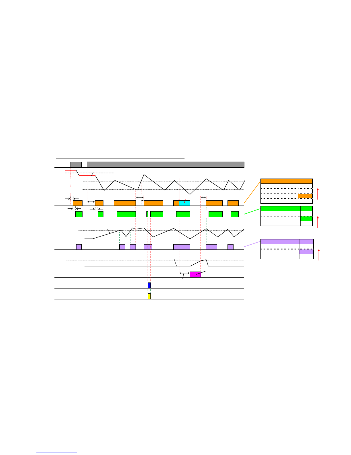
●Comp.
●Power
supply
●R-Room
Temp.
●F-Room
Temp.
●R-Fan
●Damper
●Evaporator
Temp.
●Defrost
heater
●R-Lamp
-8℃
High temp.(-16℃)
Low temp.(-22℃)
On
F-sensor
High temp.(4℃)
Low temp.(2℃)
R-sensor
On
Open
Open
On
●R-Door
(R-Door sw)
8.5℃
D-sensor
On
On
~~~~~~~~~
Off-time
10min
~~
t1t2t3t4
Pre-Cool
Off-time
10min
Pre-Cool time≦30min
Basic operation(time chart) of 508L-550L REF.
Comp. On-time:
t1+t2+t3+t4+…≧12h
High
Priority
High
Priority
ConditionComp.
Off-timeOff
DefrostingOff
F-sensor≧High temp.
On
F-sensor≦Low temp.Off
ConditionDamper
Comp. offClose
R-sensor≧High temp.Open
R-sensor≦Low temp.Close
ConditionR-Fan
R-Door openOff
Comp. onOn
Comp. offOff
Off-time
10min
High
Priority
Defrosting
30s30s
25s
26
°C
Basic operation
(
time chart
)
of
435L ~
550
L REF
.
4
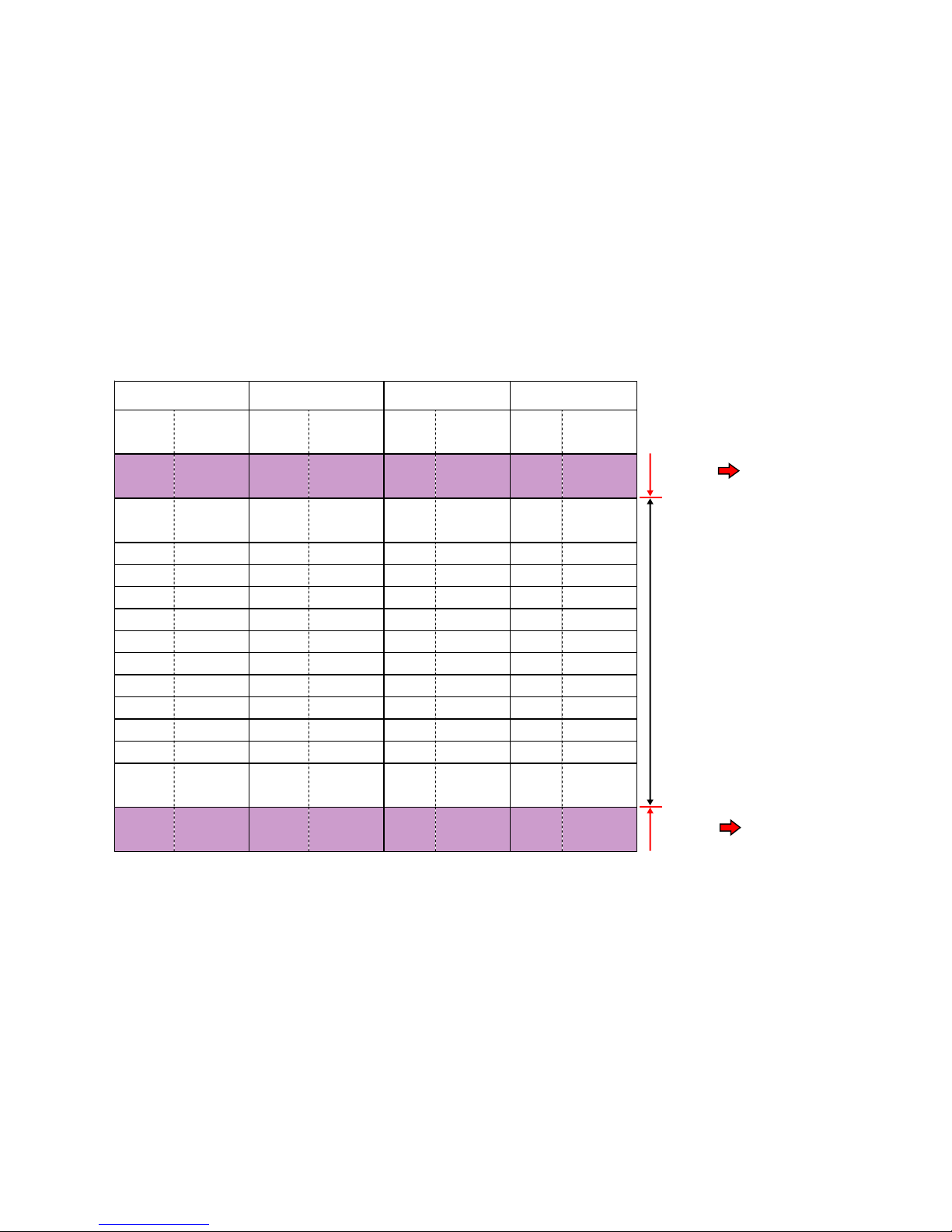
Temp.ResistanceTemp.ResistanceTemp.ResistanceTemp.Resistance
(℃)(Ω)(
℃
)(Ω)(
℃
)(Ω)(
℃
)(Ω)
~~~~~~~~
-57241.87k-2019.23k-58271.14k-20105.38k
~~~~~~~~
-2525.58k-1514.26k-2019.17k-1582.03k
-2018.9k-1010.78k-1010.83k-1060.86k
-1514.13k-58.23k-58.27k-545.67k
-1010.68k06.35k06.38k034.62k
-58.15k54.94k54.97k526.52k
06.29k103.88k103.90k1020.50k
54.90k153.08k153.09k1515.99k
103.85k202.46k202.47k2012.00k
153.05k251.98k251.98k259.97k
202.43k301.60k301.61k307.97k
251.96k351.31k401.08k356.42k
301.59k401.07k500.74k405.20k
~~~~~~~~
610.51k600.51k610.50k622.32k
~~~~~~~~
TC-sensorF-sensorR-sensorD-sensor
Normal
range
Abnormal
range
Abnormal
range
Display
Error code
Display
Error code
 Loading...