

Page 1
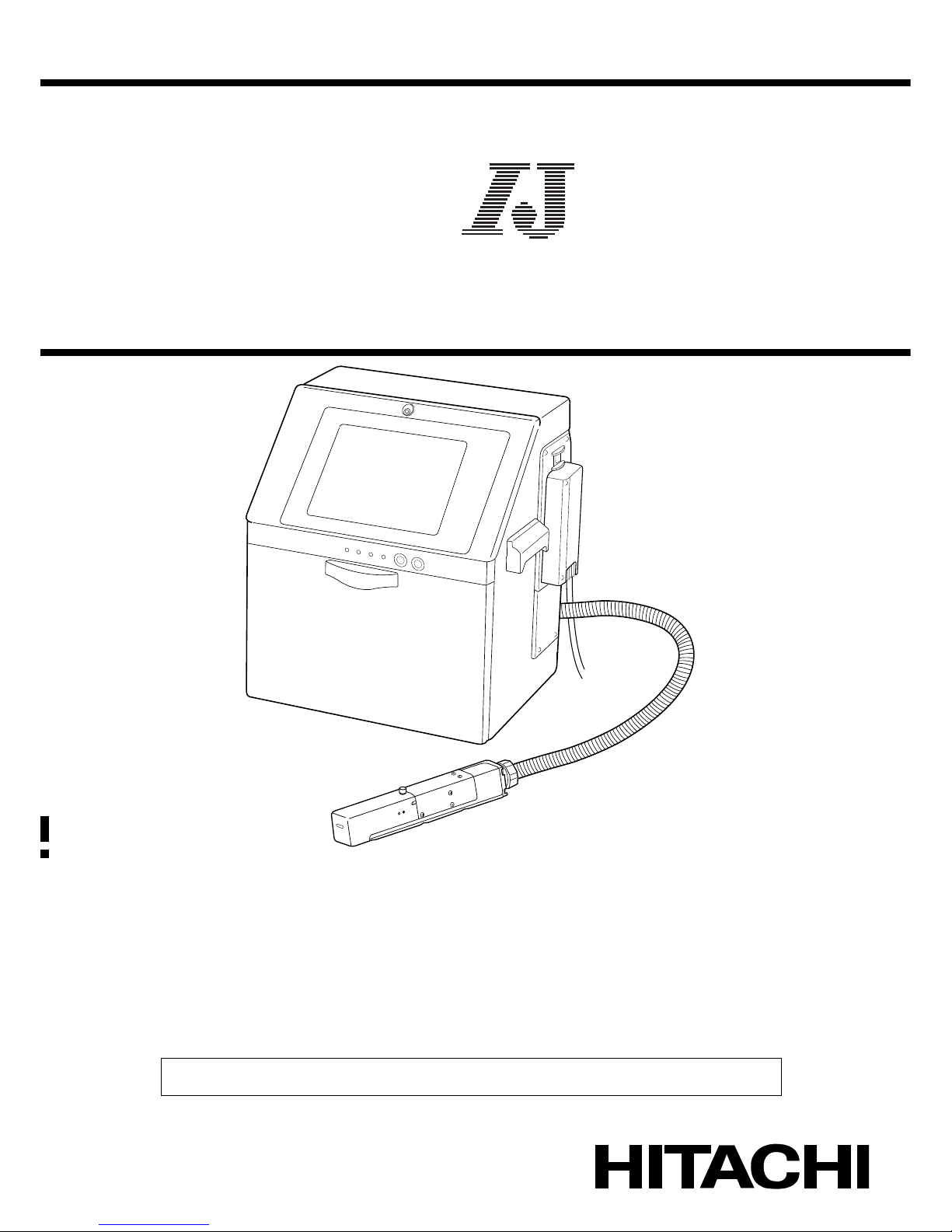
HITACHI Printer
Technical Manual
INK JET PRINTER FOR INDUSTRIAL MARKING
Model RX
Thank you for purchasing the Hitachi IJ Printer Model RX.
This printer employs a noncontact, ink-jet method to print onto a print target.
This instruction manual describes the basic operating procedures, maintenance procedures, and other detailed
handling procedures of the Hitachi IJ Printer Model RX.
If the printer is improperly handled or maintained, it may not operate smoothly and may become defective or
cause an accident. It is therefore essential that you read this manual to gain a complete understanding of the
printer and use it correctly.
After thoroughly reading the manual, properly store it for future reference.
IF you changed the language of screen by mistake,see the chapter 7.8 "Selecting Languages".
Page 2
●Safety Precautions (1)
SAFETY PRECAUTIONS
● Before using the printer, thoroughly read the following safety precautions for optimum printer
use.
● You should observe the precautions set forth below in order to use the product properly and
avoid endangering you or other persons or damaging property. For the purpose of clarifying
the severity of injury or damage and likelihood of occurrence, the precautions are classified
into two categories, WARNING and CAUTION, which both describe a hazardous situations
that may arise if you ignore the precautions and perform an incorrect handling or operating
procedure. The precautions in these two categories are both important and must therefore
be observed without fail.
WARNING
WARNING is used to indicate the presence of a hazard which
may cause severe personal injury or death if the warning against
performing an incorrect handling procedure is ignored.
CAUTION
CAUTION is used to indicate the presence of a hazard which
may cause personal injury or property damage if the warning
against performing an incorrect handling procedure is ignored.
● If the warning in the CAUTION category is ignored, serious results may occur depending on
the situation.
● After the manual has been read, it must be stored in such a location that all printer operation
personnel can refer to it at all times.
● All the instructions set forth in this manual are important and must therefore be observed
without fail.
Pictograph Examples
The symbols are used to indicate precautions (including those related to
potential warnings) to be observed. Detailed information is furnished by a picture
within the symbol outline (a shock hazard is indicated by the example shown at
left).
The symbols are used to describe prohibited actions. The details of a
prohibited action are given by a picture within or near the symbol outline (the
example shown at left dictates that you must keep flames away).
The symbols are used to describe required actions. Detailed instructions are
given by a picture within the symbol outline (the example shown at left dictates
that a ground connection must be made).
User hereby agrees not to export or re-export this product to any end-user who the user
has reason to suspect may utilize the product for the design, development or reproduction
of nuclear, chemical or biochemical weapons.
Restrictions on Export
File management and USB management are carried out using eParts made from eSOL.
Ethernet is the product name of Xerox Corporation in America.
Page 3
(2) ●Safety Precautions
SAFETY PRECAUTIONS (Continued)
WARNING
● Ensure that there is no flame- or arc-generating device around the
printer.
The ink and makeup are both flammable and may cause fire.
Fire can be generated by matches, lighters, cigarettes, heaters, stoves, gas
burners, welders, grinders and static electricity. Arcs may be generated from
open-type relays, switches, and brush motors. Before handling the ink and
makeup, remove static electricity from your body, peripheral equipment, and so
on. In the interest of safety, position a dry-chemical fire extinguisher near the
printer.
● Since the ink and makeup contain organic solvents, install the printer at
an adequately ventilated location.
Never install the printer in an enclosed space.
Connect exhaust equipment to the printer in order to prevent it from filling
with organic solvent vapor.
● Do not insert tweezers, a screwdriver, or any other metal article into the
ink ejection hole in the end of the print head.
When the printer is ready to print, a high voltage (approximately 6 kV) is applied
to the deflection electrode section in the print head.
Exercise caution to avoid electric shock, injury, and fire.
● Do not remove the outer covering.
A high voltage is applied to some sections of the printer.
Exercise caution to avoid electric shock and injury.
● Use an AC voltage of 100 to120 V or 200 to 240 V ±10% only and a
power frequency of 50 or 60 Hz only.
If the above requirements are not met, the electric parts may overheat and burn,
creating a risk of fire or electric shock.
● Never drain the ink or makeup waste solution into a public sewer system.
Waste disposal must comply with all appropriate regulations. Consult the
appropriate regulatory agency for further information.
● Exercise caution to avoid inadvertently disconnecting, forcibly pulling, or
bending piping tubes.
Since the ink and makeup in some portions of piping tubes are pressurized,
they may splash into your eyes or mouth or onto your hands or clothing.
If any ink or makeup enters your eyes or mouth, immediately flush with warm or
cold water and consult a physician.
1
2
Page 4
●Safety Precautions (3)
SAFETY PRECAUTIONS (Continued)
WARNING
● While the printer is operating, do not look into the ink ejection hole in the
end of the print head.
Ink or makeup may enter your eyes or mouth or soil your hands or clothing.
If any ink or makeup enters your eyes or mouth, immediately flush with warm or
cold water and consult a physician.
● Before servicing the printer, be sure to stop the ink ejection.
Because ink or makeup may splash into your eyes or mouth or onto your hands
or clothing. If any ink or makeup enters your eyes or mouth, immediately flush
with warm or cold water and consult a physician.
● If an earthquake, fire, or other emergency occurs while the printer is
engaged in printing or just turned on, press the Main power switch to turn
off the power.
● The printer must be managed in compliance with all appropriate
regulations.
Read and understand the appropriate Material Safety Data Sheet (MSDS)
before using any ink or makeup.
● Use Hitachi approved consumables and periodic replacement parts.
Using products that are not designated by Hitachi could cause s failure in
certain functions.
● Warning for Mercury
-- THE LAMP IN THIS PRODUCT CONTAINS MERCURY.
RECYCLE OR DISPOSE OF IT ACCORDING TO APPLICABLE
ENVIRONMENTAL LAWS.
For Recycling and Disposal information, contact your government agency, the
Electronic Industries Alliance at www.eiae.org, and/or www.lamprecycle.org (in
the US), or the Electronic Product Stewardship Canada at www.epsc.ca (in
Canada). For more information, call 1-800-HITACHI (1-800-448-2244) (in the
US).
Hg
Page 5
(4) ●Safety Precautions
SAFETY PRECAUTIONS (Continued)
WARNING
● When charging a refill of ink or makeup, exchanging ink, or otherwise
handling ink or makeup, take enough care not to spill ink or makeup.
If you spill any ink or makeup by mistake, wipe it off neatly and promptly
with wiping paper or something similar. Do not close the maintenance
cover until you make sure that the portion you have just wiped is
completely dry.
You must pay particular attention when you have spilled ink or makeup
inside the printer and it is not completely dry. Why? Because vapors of
ink or makeup will stay inside the printer and may catch on or cause a
fire.
If you find it hard to wipe the printer when it is turned on, stop it with the
maintenance cover open. Power it down, and then wipe it off again.
● If you wish to clean the casing of the printer with wiping paper
impregnated with makeup, be sure to do so with the power off.
Attempting to clean it when the power is on will cause makeup or vapors of
makeup to enter the printer, possibly catching on or causing a fire.
When the cleaning is over, open the maintenance cover and make sure that no
makeup has entered and no vapors remain inside.
● Should you find a leak of ink or makeup inside the printer while the
printer is running or being maintained, wipe it off promptly with wiping
paper or something similar. Then, with the maintenance cover open,
stop the printer, power it down, and repair the leak.
Continuing operation with a leak of ink or makeup will cause an anomaly,
resulting in abnormal printing.
Ink and makeup are flammable. They may therefore catch on or cause a fire.
● If you wish to receive ink particles in a beaker, for a printing test for
example, use an electrically conductive beaker and connect the beaker
securely to the ground.
Do not let the tip of the printing head enter the beaker.
Ink particles used for printing are electrically charged. An ungrounded beaker
has a gradually rising charge, possibly catching on or causing a fire.
● Ensure that all electrical wiring, connections and grounding comply with
applicable cords. Properly connect the printer to its dedicated ground.
Complete the above procedure to avoid electrical shock hazards.
● When welding, keep enough space between the IJ printer and the
welding work area to prevent the arc from starting a fire. Also, be sure to
insulate the printhead and IJ printer frame to keep the welding current
from flowing to the control section of the printer, and to make a separate
ground connection for the printer.
Page 6
●Safety Precautions (5)
SAFETY PRECAUTIONS (Continued)
CAUTION
● Only persons who have completed an operator training course for
Hitachi IJP can operate and service the printer.
If the printer is operated or serviced incorrectly, it may malfunction or break
down.
● Do not attempt to make repairs for any purpose other than operation or
maintenance.
● Since the ink and makeup contain organic solvents, observe the
following handling precautions.
Secure adequate space for the ink/makeup handling area and printer
installation site. At least 200 m must be provided per print head.
Ensure that adequate ventilation is provided.
When handling the ink or makeup, wear protective gloves and safety goggles
to avoid direct skin contact. If the ink or makeup comes into contact with skin,
wash thoroughly with soap and warm or cold water.
When transferring the ink or makeup to or from a bottle, exercise caution to
prevent it coming into contact with the printer or surrounding articles.
If there is any spillage, immediately wipe it clean using a cloth moistened
with makeup.
● Ink and makeup must be stored as flammable liquids. Storage must
comply with local regulatory requirements. Consult the appropriate
regulatory agency for further information.
● If extraneous noise enters the printer, it may malfunction or break down.
For maximum noise immunity, observe the following installation and wiring
precautions.
Ensure that 100 to 120 VAC or 200 to 240 VAC power cables are not
bundled with other power supply cables.
Insulate the printer main body and print head so that they do not come into
direct contact with the conveyor or other devices.
If the employed print target detector is housed in a metal case, use a plastic
mounting brace for the purpose of insulating the detector from the conveyor
and other devices.
Be sure that the print target detector wiring is not bundled together with other
power supply cables.
● Please make sure the print status and print content are correct each time when
you start operation of IJP.
● Please implement periodical checkup of print status in the process, even
including during production.
● A touch panel is employed for data entry to operation screen.
When manipulating the Touch panel, use only fingers. If the touch panel is
operated with metal and/or sharp objects such as ball point pen, it may
malfunction or break down.
1
2
3
3
2
1
3
4
Page 7
(6) ●Safety Precautions
SAFETY PRECAUTIONS (Continued)
FCC Notice
This device complies with part 15 of the FCC Rules. Operation is subject to the following two
conditions: (1) This device may not cause harmful interference, and (2) this device must accept
any interference received, including interference that may cause undesired operation.
This equipment has been tested and found to comply with the limits for a Class A digital device,
pursuant to part 15 of the FCC Rules. These limits are designed to provide reasonable protection
against harmful interference when the equipment is operated in a commercial environment.
This equipment generates, uses, and can radiate radio frequency energy and, if not installed and
used in accordance with the instruction manual, may cause harmful interference to radio
communications. Operation of this equipment in a residential area is likely to cause harmful
interference in which case the user will be required to correct the interference at his own expense.
Page 8

●Contents 1
1. DELIVERED GOODS . . . . . . . . . . . . . . . . . . . . . . . . . . . . 1-1
2. INSTALLING PRECAUTIONS . . . . . . . . . . . . . . . . . . . . . 2-1
3. INSTALLATION CHECK ITEMS . . . . . . . . . . . . . . . . . . . . 3-1
3.1 Print head air purge . . . . . . . . . . . . . . . . . . . . . . . . . . . . . . . . . . . . . . . . . . 3-1
3.2 Setting functions which can be performed . . . . . . . . . . . . . . . . . . . . . . . . . 3-2
3.3 Selecting user when power is turned on . . . . . . . . . . . . . . . . . . . . . . . . . . 3-5
4. ELECTRIC SIGNAL CONNECTION . . . . . . . . . . . . . . . . . 4-1
4.1 Wiring precautions . . . . . . . . . . . . . . . . . . . . . . . . . . . . . . . . . . . . . . . . . . . 4-1
4.2 Input/output (I/O) signal connection . . . . . . . . . . . . . . . . . . . . . . . . . . . . . . 4-3
4.2.1 Wiring the I/O line. . . . . . . . . . . . . . . . . . . . . . . . . . . . . . . . . . . . . . . . . . . . . . . . . . . . 4-3
4.2.2 Connection to input/output (I/O) terminal . . . . . . . . . . . . . . . . . . . . . . . . . . . . . . . . . . 4-5
4.3 Input/output (I/O) specifications . . . . . . . . . . . . . . . . . . . . . . . . . . . . . . . . . 4-8
4.3.1 Print target detector input . . . . . . . . . . . . . . . . . . . . . . . . . . . . . . . . . . . . . . . . . . . . . . 4-9
4.3.2 Product speed matching function using a rotary encoder . . . . . . . . . . . . . . . . . . . . 4-12
4.3.3 Input function . . . . . . . . . . . . . . . . . . . . . . . . . . . . . . . . . . . . . . . . . . . . . . . . . . . . . . 4-17
4.3.4 Output function . . . . . . . . . . . . . . . . . . . . . . . . . . . . . . . . . . . . . . . . . . . . . . . . . . . . . 4-21
4.3.5 Product speed matching function without a rotary encoder (RX-S only) . . . . . . . . . 4-24
5. COMMUNICATION (Optinal on RX-B) . . . . . . . . . . . . . . . 5-1
5.1 Overview. . . . . . . . . . . . . . . . . . . . . . . . . . . . . . . . . . . . . . . . . . . . . . . . . . . 5-1
5.2 Setting Communication Environment . . . . . . . . . . . . . . . . . . . . . . . . . . . . . 5-3
5.2.1 Setting Communication Environment . . . . . . . . . . . . . . . . . . . . . . . . . . . . . . . . . . . . . 5-3
5.5.2 Transmission Specifications . . . . . . . . . . . . . . . . . . . . . . . . . . . . . . . . . . . . . . . . . . . 5-5
5.3 Transmission Sequences . . . . . . . . . . . . . . . . . . . . . . . . . . . . . . . . . . . . . . 5-6
5.3.1 Common Transmission Sequences . . . . . . . . . . . . . . . . . . . . . . . . . . . . . . . . . . . . . . 5-6
5.3.2 Printings Transmission . . . . . . . . . . . . . . . . . . . . . . . . . . . . . . . . . . . . . . . . . . . . . . . 5-7
5.3.3 Print Data Recall Transmission . . . . . . . . . . . . . . . . . . . . . . . . . . . . . . . . . . . . . . . . . 5-9
5.3.4 Print data registration transmission . . . . . . . . . . . . . . . . . . . . . . . . . . . . . . . . . . . . . 5-10
5.3.5 Print Condition Transmission . . . . . . . . . . . . . . . . . . . . . . . . . . . . . . . . . . . . . . . . . . 5-12
5.3.6 Calendar Conditions Transmission. . . . . . . . . . . . . . . . . . . . . . . . . . . . . . . . . . . . . . 5-19
5.3.7 User Pattern Character Transmission . . . . . . . . . . . . . . . . . . . . . . . . . . . . . . . . . . . 5-22
5.3.8 On-line/Off-line Transmission Procedure . . . . . . . . . . . . . . . . . . . . . . . . . . . . . . . . . 5-29
5.3.9 Remote Operation Transmission . . . . . . . . . . . . . . . . . . . . . . . . . . . . . . . . . . . . . . . 5-30
5.3.10 Time control . . . . . . . . . . . . . . . . . . . . . . . . . . . . . . . . . . . . . . . . . . . . . . . . . . . . . . 5-31
CONTENTS
Page 9

2 ●Contents
5.4 Code Tables . . . . . . . . . . . . . . . . . . . . . . . . . . . . . . . . . . . . . . . . . . . . . . . 5-33
5.4.1 Code Tables . . . . . . . . . . . . . . . . . . . . . . . . . . . . . . . . . . . . . . . . . . . . . . . . . . . . . . . 5-33
5.4.2 Header Table . . . . . . . . . . . . . . . . . . . . . . . . . . . . . . . . . . . . . . . . . . . . . . . . . . . . . . 5-42
5.5 Communication Timing. . . . . . . . . . . . . . . . . . . . . . . . . . . . . . . . . . . . . . . 5-44
5.5.1 Signal Timing . . . . . . . . . . . . . . . . . . . . . . . . . . . . . . . . . . . . . . . . . . . . . . . . . . . . . . 5-44
5.5.2 Response Time. . . . . . . . . . . . . . . . . . . . . . . . . . . . . . . . . . . . . . . . . . . . . . . . . . . . . 5-44
5.6 Communication Monitor Function. . . . . . . . . . . . . . . . . . . . . . . . . . . . . . . 5-50
5.7 Warning Messages. . . . . . . . . . . . . . . . . . . . . . . . . . . . . . . . . . . . . . . . . . 5-51
5.8 Precautions . . . . . . . . . . . . . . . . . . . . . . . . . . . . . . . . . . . . . . . . . . . . . . . 5-53
5.8.1 Notes on Product speed matching Feature Use. . . . . . . . . . . . . . . . . . . . . . . . . . . . 5-53
5.8.2 Notes on Print Condition Transmission . . . . . . . . . . . . . . . . . . . . . . . . . . . . . . . . . . 5-53
5.9 Communication Buffer . . . . . . . . . . . . . . . . . . . . . . . . . . . . . . . . . . . . . . . . . . . . . . . . . 5-54
5.9.1 Overview. . . . . . . . . . . . . . . . . . . . . . . . . . . . . . . . . . . . . . . . . . . . . . . . . . . . . . . . . . 5-54
5.9.2 Description of Functions . . . . . . . . . . . . . . . . . . . . . . . . . . . . . . . . . . . . . . . . . . . . . . 5-55
5.9.3 External Communications. . . . . . . . . . . . . . . . . . . . . . . . . . . . . . . . . . . . . . . . . . . . . 5-58
5.9.4 Errors . . . . . . . . . . . . . . . . . . . . . . . . . . . . . . . . . . . . . . . . . . . . . . . . . . . . . . . . . . . . 5-59
6. CIRCULATION SYSTEM WORK AND ADJUSTMENT
METHOD . . . . . . . . . . .6-1
6.1 Circulation control screen operation. . . . . . . . . . . . . . . . . . . . . . . . . . . . . . 6-2
6.2 Circulation control contents . . . . . . . . . . . . . . . . . . . . . . . . . . . . . . . . . . . . 6-3
6.3 Replacing the ink . . . . . . . . . . . . . . . . . . . . . . . . . . . . . . . . . . . . . . . . . . . . 6-4
6.4 How to correct ink stream bending and nozzle clogging . . . . . . . . . . . . . . 6-7
6.4.1 Nozzle backwash . . . . . . . . . . . . . . . . . . . . . . . . . . . . . . . . . . . . . . . . . . . . . . . . . . . . 6-7
6.4.2 Nozzle orifice disassembly and cleaning . . . . . . . . . . . . . . . . . . . . . . . . . . . . . . . . . . 6-9
6.5 Stream alignment . . . . . . . . . . . . . . . . . . . . . . . . . . . . . . . . . . . . . . . . . . . 6-11
6.6 Cleaning the recovery line . . . . . . . . . . . . . . . . . . . . . . . . . . . . . . . . . . . . 6-13
6.7 Replacing the ink filter . . . . . . . . . . . . . . . . . . . . . . . . . . . . . . . . . . . . . . . 6-14
6.8 Replacing the recovery filter and makeup filter . . . . . . . . . . . . . . . . . . . . 6-16
6.9 Adjusting the pressure . . . . . . . . . . . . . . . . . . . . . . . . . . . . . . . . . . . . . . . 6-18
6.10 Excitation V adjustment . . . . . . . . . . . . . . . . . . . . . . . . . . . . . . . . . . . . . 6-19
6.11 Ink drop state check method. . . . . . . . . . . . . . . . . . . . . . . . . . . . . . . . . . 6-22
6.12 Draining ink from the main ink tank . . . . . . . . . . . . . . . . . . . . . . . . . . . . 6-24
6.13 Test of solenoid valve/pump . . . . . . . . . . . . . . . . . . . . . . . . . . . . . . . . . . 6-25
6.14 Long-term Shutdown . . . . . . . . . . . . . . . . . . . . . . . . . . . . . . . . . . . . . . . 6-26
6.14.1 Process prior to long-term shutdown . . . . . . . . . . . . . . . . . . . . . . . . . . . . . . . . . . . 6-27
6.14.2 Startup process after long-term shutdown . . . . . . . . . . . . . . . . . . . . . . . . . . . . . . . 6-32
Page 10

●Contents 3
7. MAINTENANCE SERVICE . . . . . . . . . . . . . . . . . . . . . . . . 7-1
8. SCHEMATIC DIAGRAMS . . . . . . . . . . . . . . . . . . . . . . . . . 8-1
8.1 Outside Dimensions . . . . . . . . . . . . . . . . . . . . . . . . . . . . . . . . . . . . . . . . . . 8-1
8.2 Electrical Connection Diagram . . . . . . . . . . . . . . . . . . . . . . . . . . . . . . . . . . 8-3
8.3 Circulation System Diagram . . . . . . . . . . . . . . . . . . . . . . . . . . . . . . . . . . . . 8-5
9. APPENDIX. . . . . . . . . . . . . . . . . . . . . . . . . . . . . . . . . . . . . 9-1
● Barcode, 2-dimensional code . . . . . . . . . . . . . . . . . . . . . . . . . . . . . . . . . . . . 9-2
● Setting high-speed printing . . . . . . . . . . . . . . . . . . . . . . . . . . . . . . . . . . . . . . 9-4
● Change of Buttons, Icons and Status Colors . . . . . . . . . . . . . . . . . . . . . . . . . 9-5
● Icon List . . . . . . . . . . . . . . . . . . . . . . . . . . . . . . . . . . . . . . . . . . . . . . . . . . . . . 9-9
● Index . . . . . . . . . . . . . . . . . . . . . . . . . . . . . . . . . . . . . . . . . . . . . . . . . . . . . . 9-12
Page 11
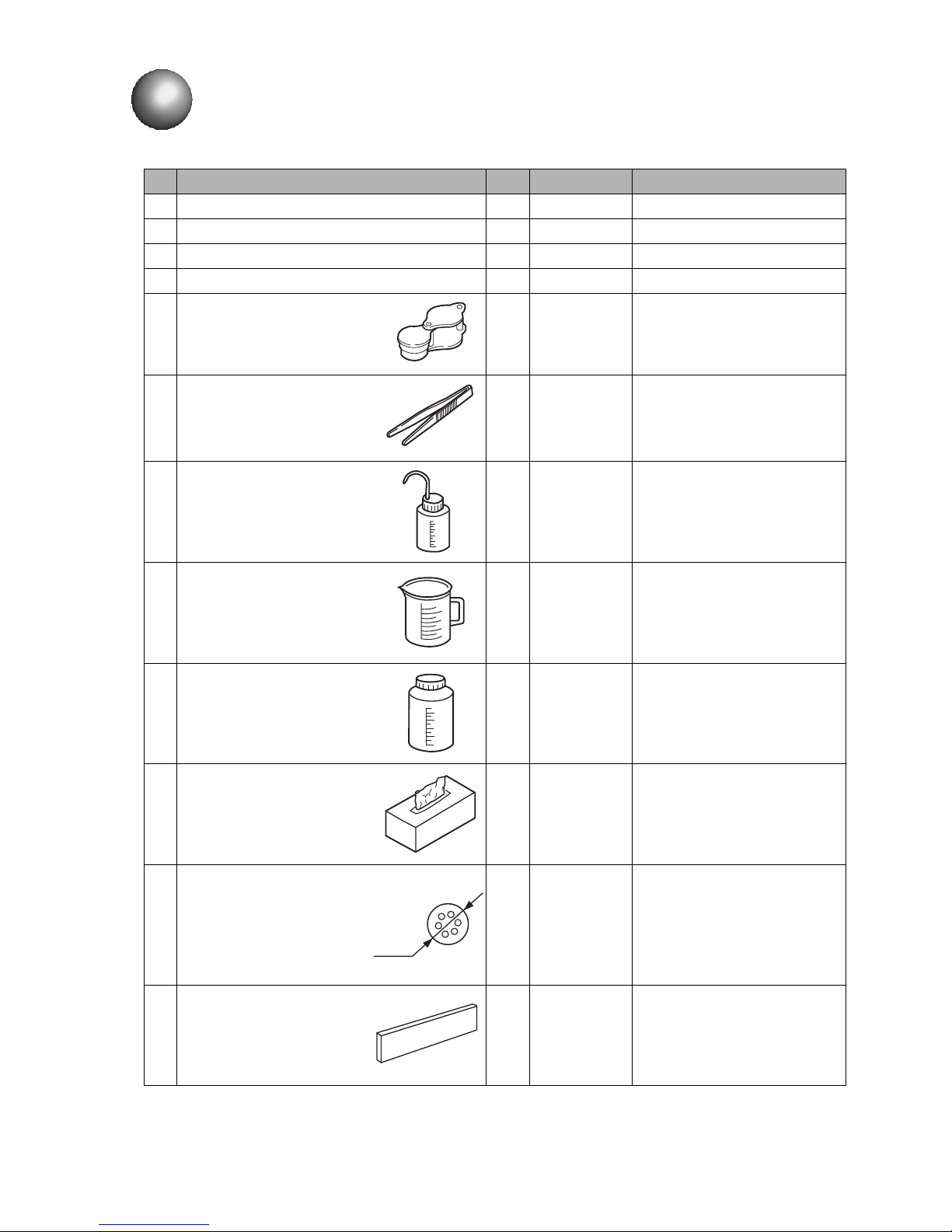
1-1 ●Delivered goods
No. Part Name Qty Product code. Remarks
1 IJ printer body 1 -
2 Instruction manual 1 -
3 Technical manual 1 -
4 One-page sheet 1 -
5 Magnifying glass 1 451274
Used in ink particles shape
check, ink beam position check,
etc.
6 Tweezers 1 451412
Used when removing the
orifice, etc.
7 Cleaning bottle 1 451058
Filled with makeup and used in
print head cleaning, etc.
8 Beaker with handle 1 451410
Used in print head cleaning, ink
replacement, etc.
9 Wide mouth bottle 1 451126 Use to hold the waste liquid.
10 Wiping paper 1 -
Use for wiping after print head
cleaning, etc.
11 Nozzle seal plate 3 451913
Orifice plate seal packing
(spare part)
12 Cable seal 3 -
Seal for power cable and ]
external communications cable.
φ7.2
1. DELIVERED GOODS
●Unpack the equipment and check the delivered goods.
Page 12
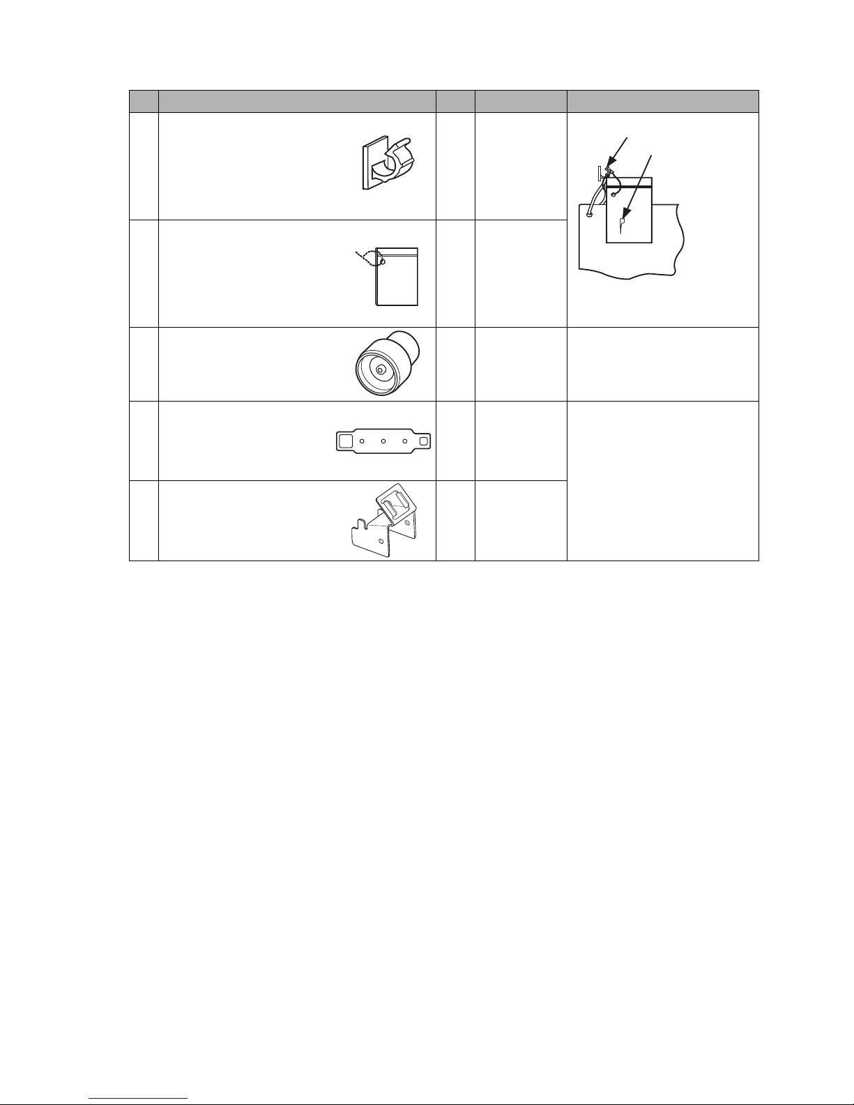
●Delivered goods 1-2
No. Part Name Qty Product code Remarks
13 Cable clip 1 -
14 Plastic bag with zipper 1 -
15 Mini Filter 1 451857
Recovery filter,
Makeup filter
(Spare parts)
16 Nozzle tool A 1 451939
Used when removing the
orifice.
17 Nozzle tool B 1 451940
Cable clip
Nozzle rubber seal
One page sheet
Use to store the one page
sheet and nozzle rubber seal.
Note “Part Name” and “Product code” when ordering the parts.
Page 13
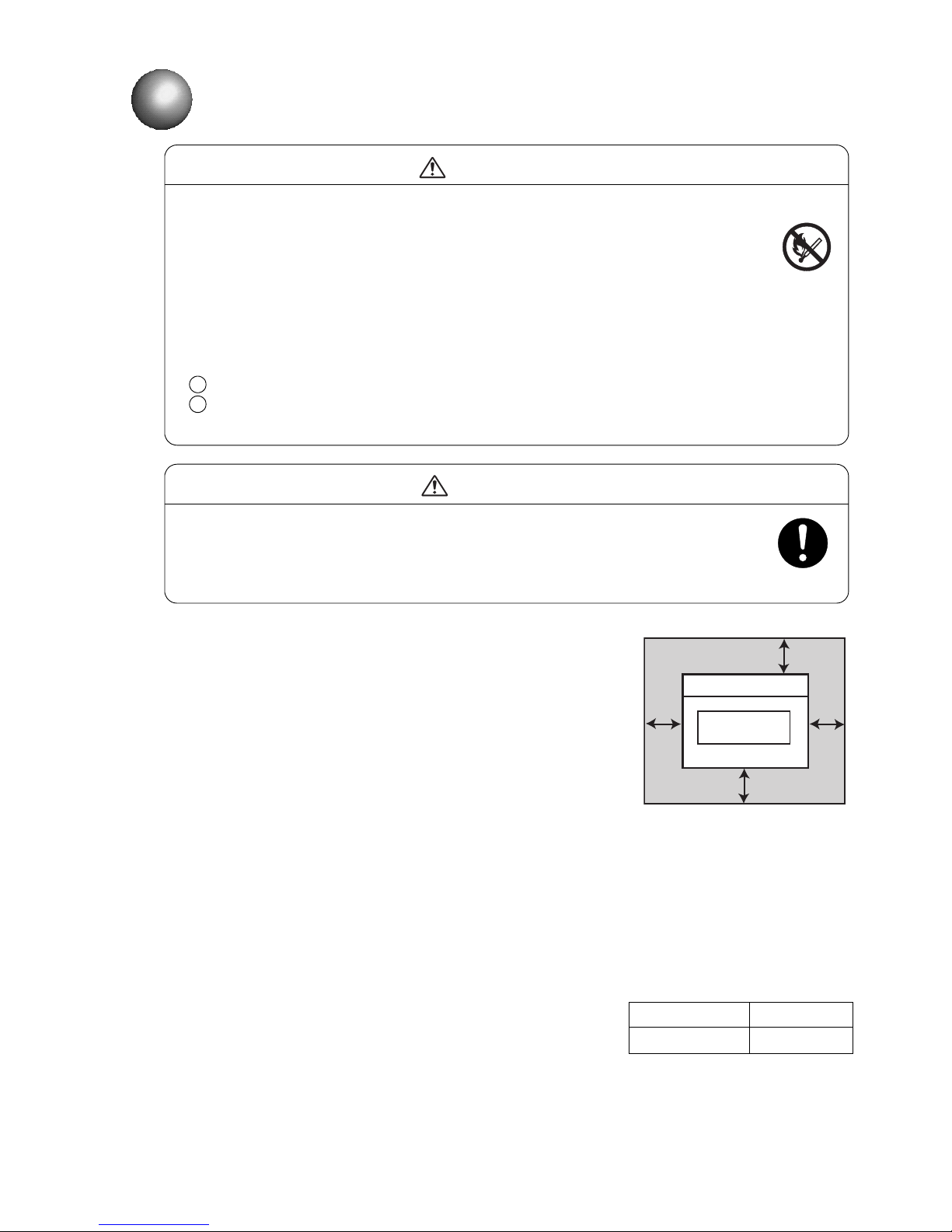
2-1 ●Installing Precautions
● The employed ink and makeup contain organic solvents. Furnish an
adequate space for the ink/makeup handling area and printer
installation site. A space of at least 200 m must be provided per print head.
Ensure that adequate ventilation is provided. Follow all regulation in your
country.
CAUTION
3
IJ printer
Maintenance area
300
mm
Top view
300
mm
300mm
750mm
2. INSTALLING PRECAUTIONS
● Ensure that there is no flame- or arc-generating device around the printer.
The ink and makeup are both flammable and may cause fire.
Fire can be generated by matches, lighters, cigarettes, heaters, stoves, gas burners,
welders, grinders and static electricity. Arcs may be generated from open-type relays,
switches, and brush motors. Before handling the ink and makeup, remove static
electricity from your body, peripheral equipment, and so on. In the interest of safety,
position a dry-chemical fire extinguisher near the printer.
● Since the ink and makeup contain organic solvents, install the printer at an
adequately ventilated location.
Never install the printer in an enclosed space.
Connect exhaust equipment to the printer in order to prevent it from filling with
organic solvent vapor.
WARNING
2
1
(1) Provide a clearance around the IJ printer for daily operation,
handling, and maintenance access (see the figure at right).
(2) The print head needs to be cleaned with the makeup while the
printer is operated and stopped (daily maintenance). Adopt a fixed
structure in consideration of print head cover and print head
removal.
(3) Installation must be completed so that no vibration will be applied to
the IJ printer main body, print head, or print head cable.
If they are vibrated, print quality deterioration and print irregularity
may be incurred (the maximum permissible vibration value is
1.96m/s ).
(4) The IJ printer main body must be installed with a levelness error of
not over ±1°.
(5) The IJ printer main body must be electrically insulated from the
other equipment (conveyors, packing machines,etc.), photoelectric
switches, and the rotary encoder.
(6) The standard distance between the printing head and the object to be
printed on is as indicated in the right-hand table.
The smaller the clearance between the print head and print target,
the smaller the character height and the better printing.
(7) The IJ printer proper requires maintenance as the occasion may
demand including replenishment of ink and makeup and
replacement of filter.
(8) If ambient humidity is 85 to 90%RH, you must purge inside of print
head by air.
It is necessary for dry-clean air, regulator for pressure of air and air
filter.
(Quantities of the air are 1L / minutes.)
* Leave a maintenance area of
at least 20 cm for the upside
of printer.
Distance between the printing head
and the object to be printed on
Nozzle diameter Distance
65μm
10 to 30mm
2
Page 14
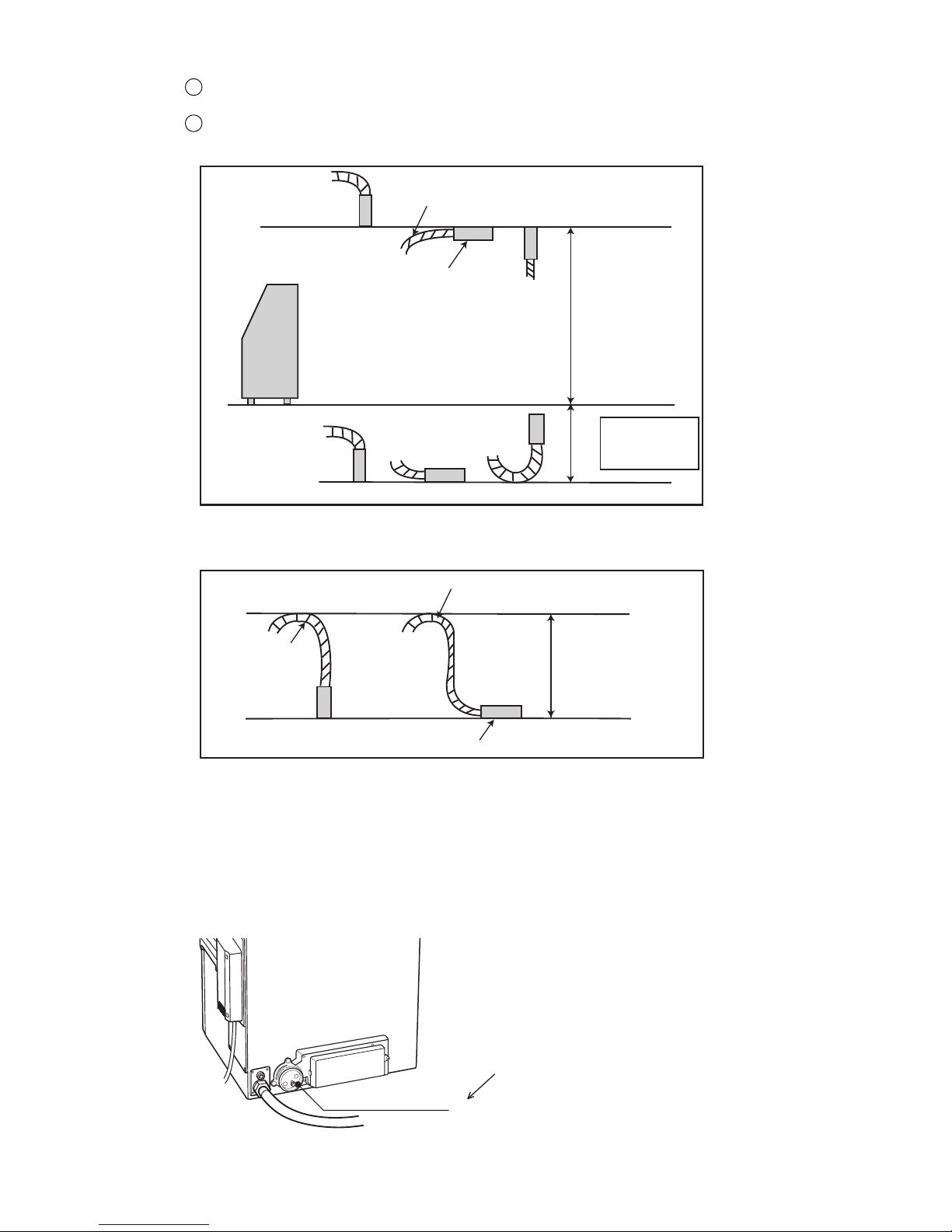
●Installing Precautions 2-2
Upward printing
Lateral printing
Downward printing
Print head
cable included
1m
1.5m
Print head
Print head cable
Main body installation surface
IJ printer
main body
Print head
Print head cable
Bend R
0.5m
Connect a duct to this port
(50 mm in diameter).
Exhaust duct
connection port
(9) When installing the print head and print head cable, comply with the following conditions.
When positioning the end of the print head above the printer main body installation surface,ensure
that the distance between the end of the print head and the installation surface does not exceed 1.5 m.
When positioning the end of the print head below the printer main body installation surface, ensure
that the distance between the end of the print head and the installation surface does not exceed 1 m.
2
1
(10) When using the printer for upward or lateral printing, ensure that the rising print head cable upper end
is positioned not more than 0.5 m above the print head.
(11) If you fixed the print head, ensure that the minimum bend radius of the print head cable is at least 150
mm.
(12) The ink stream may bend for some reason or other (due, for instance, to dirt).
The facilities positioned in the direction of ink ejection should be partially covered as needed to avoid
ink accumulation.
(13) When connecting an exhaust duct to the printer, install a damper and adjust the wind velocity at the
intake port to 0.3 to 0.5 m/s. (Use an anemometer for verification. If the wind velocity is too high, the
makeup consumption increases.)
Page 15
2-3 ●Installing Precautions
(14) If you try to fix the print head with a magnetic substance (such as iron), the cover switch will
malfunction resulting in an "Cover Open" error.
This, you must only use nonmagnetic resins or metals for fixing the print head.
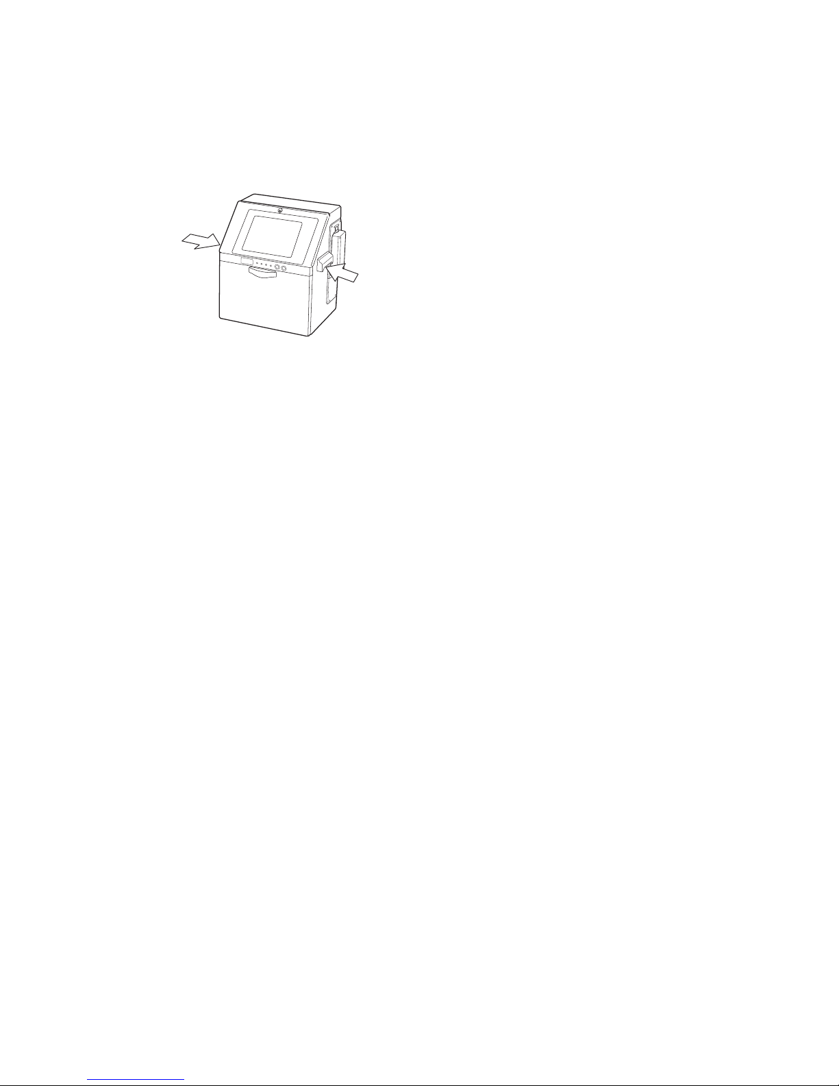
(15) In the case of carrying the printer proper, use the handles in the drawing below.
Page 16
●Print head air purge 3-1
Pressuregauge
Pressurereducingvalve
Printheadairpurge
connectionport
Backofbody
Airsource
(cleandryair)
(capacity:Approx.1L/min)
Madeofresin.Becarefulnotto
tightentootightlywhenconnecting
withametaljoint.
0.1〜0.3MPa
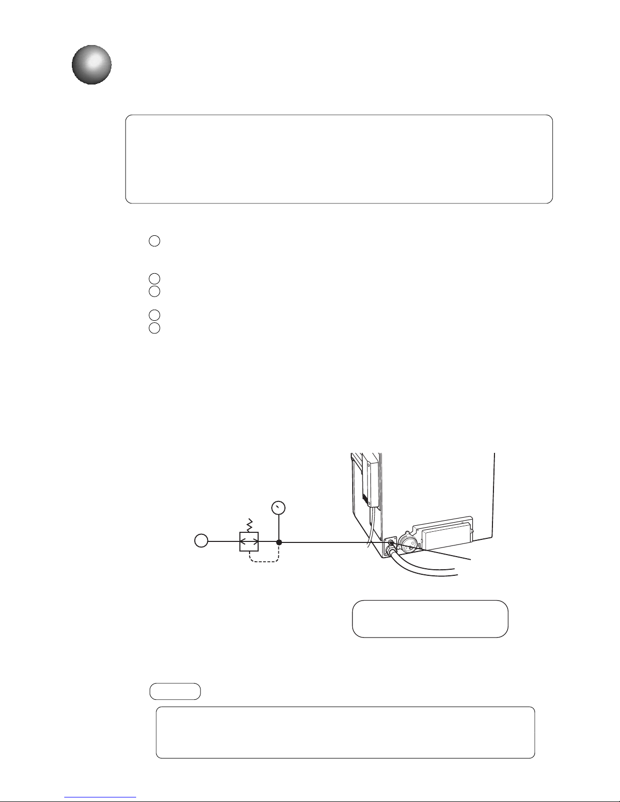
3.1 Print head air purge
If the makeup remains in the electrode section after cleaning or if you use the IJ
printer at a high humidity, moisture condensation may occur within the print head,
causing leakage from the deflection electrode section. It is also important to
remember that dust or splashed ink accumulation on the deflection electrode
section may cause leakage. Performing the following air purge procedure for the
print head interior is effective in preventing such leakage.
3. INSTALLATION CHECK ITEMS
If the air-purge amount is excessive, print irregularities may occur.
After air-purge pressure adjustment, be sure to perform a printing test to
verify the printing results.
(1) Situations requiring an air purge
When the printer is used in a highly humid place such as a beer or other beverage can line
(If you use the printer in an environment in which the relative humidity is 85% or higher,
complete the print head air-purge procedure).
When a water drainage blow sequence is performed before printing.
When the printer is used in a place where a considerable amount of paper powder or other dust
exists.
When the printing distance is short so that the end of the print head is splashed with ink.
When you use inks that are indicated on the handling guidance of each ink to complete
air-purge procedure.
(2) Air-purging procedure
Introduce clean dry air into the print head air purge connection port (Rc 1/8 (PT 1/8)×screw) in
the rear of the printer main body at a pressure of about 0.1 to 0.3 MPa. If it is possible that the
employed air tanks oil or water, turn it into clean dry air with an air filter, micro-mist separator, or
the like before introducing it into the printer main body.
1
2
3
4
5
NOTICE
Max. tightening torque:1.5N m
.
Page 17

3-2 ●Checking functions which can be performed
4
3.2 Setting functions which can be performed
(1) Functions
●Sets whether or not each function is enabled or disabled for each login user.
●The operation buttons of disabled functions are not displayed or the screen cannot be entered.
●”User conditions setup” and “Using environment setup” can be started when the administrator logs in.
●The function restrictions state can be checked at the function restrictions screen. (Refer to “Instruction
manual 5.5 Checking functions which can be performed”)
Protected functions
Item Protected function name
Edit message
●Edit message
●Calendar conditions
●Substitution rules setting
●Count conditions
Select message ●Select message
Save message
●Save message
●Overwrite message
Print specifications
●Print specifications
●Various print setup
●Adjust print parameters
Print format
●Print format
●Adjust inter-character space
Maintenance
[Auxiliary functions]
●Manage messages/group
●Create user pattern
●Calibrate touch screen coordinates
●Copy data (IJP→USB)
●Copy data (USB→IJP)
●Edit standard pattern
●Edit substitution rules
●Select language
[Environment setup]
●User environment setup
●Date/time setup
●Communication environment setup
●Touch screen setup
[Maintenance work]
●Operation management
●Excitation V update
●Circulation control
●Solenoid valve/pump test
Password setup ●Password setup
Page 18
●Checking functions which can be performed 3-3
Login management menu
2015.07.0712:45
Back
Com=0
[Stop ]
Login history Select login user Password setup
User conditions
setup
Using environment
setup
Startup
M
Manual
HOME
Create new user ID Delete user ID
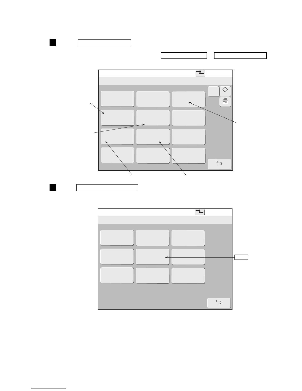
Sets whether or
not to select a
user which logs
in when power
is turned on.
Sets function
restrictions for
each user.
Sets the password.
Delete the user.
Create the new user.
Press Login management of the Environment setup menu.
The Login management menu is displayed.
Log in as a user with administrator rights when User conditions setup or Using environment setup are
not displayed on Login management menu.
1
(2) Operation
The administrator is logged in.
Press User conditions setup .
The User conditions setup screen is displayed.
A user list is displayed.
2
User conditions setup
2015.07.0712:45
Back
Com=0
[Stop ]
admin user2 user3
user4
user5
Current user ID : admin
user5
Page 19
3-4 ●Checking functions which can be performed
User conditions setup
2015.07.0712:45
Com=0
[Stop ]
Edit message
Select message
Save message
Print specifications
Print format
Maintenance
Password update
ID:5
Administrator rights
User5
OK
Cancel
access
protect
access
protect
access
protect
access
protect
access
protect
access
protect
access
protect
Users
Administrator
Password
setup
Startup
M
Manual
HOME
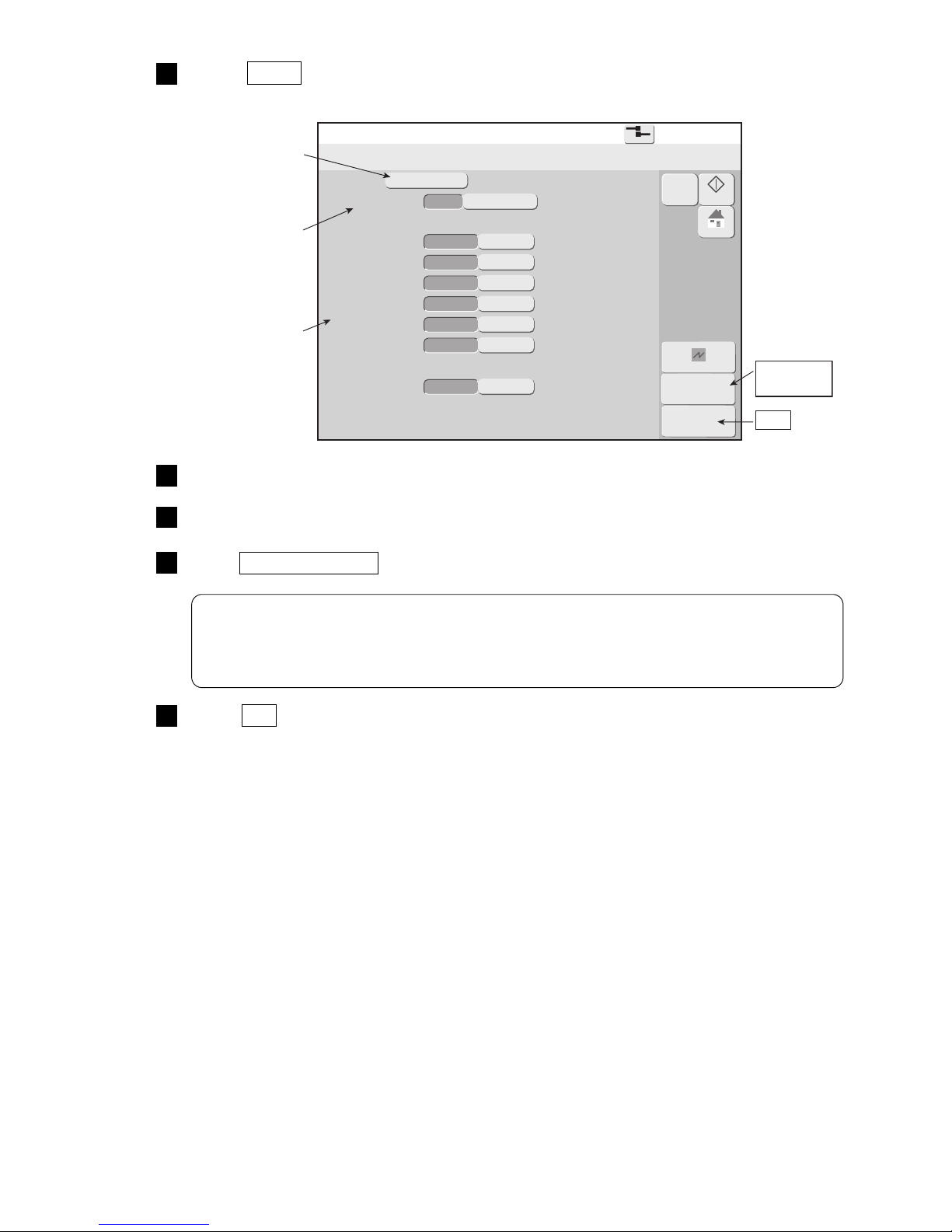
Sets function
restrictions.
Displays the kind
of administrator
rights.
OK
Password
setup
Modifies the user
name.
Select User5 .
“User5” settings are displayed.
3
Select the administrator rights.
4
Select “access” or “protect” for each function item.
5
Press Password setup and set the password.
6
Press OK .
The administrator rights, function restrictions, user name, and password for user “User5” are set.
7
An error message appears when the entry in the old password input field does not agree
with the current password.
However, the error does not occur if you type in "IGNOREPW" as the password.
Use this word if you forget your password.
Page 20
●Selecting user when power is turned on 3-5
3.3 Selecting user when power is turned on
(1) Functions
●Sets whether or not to select a user which logs in when power is turned on.
Possible login methods
Login method “Disable” Login method “Enable”
Operation when power is
turned on
Immediately displays the Print
description screen when the power
is turned on. The login user is
decided beforehand.
Selects the user which logs in when
the power is turned on.
●The login user can be changed by login user change function even when the login method is “Disable”.
●”User conditions setup” and “Using environment setup” can be started when the administrator is logged in.
(2) Operation
Log in the administrator.
Login management menu
2015.07.0712:45
Back
Com=0
[Stop ]
Login history Select login user Password setup
User conditions
setup
Using environment
setup
Startup
M
Manual
HOME
Create new user ID Delete user ID
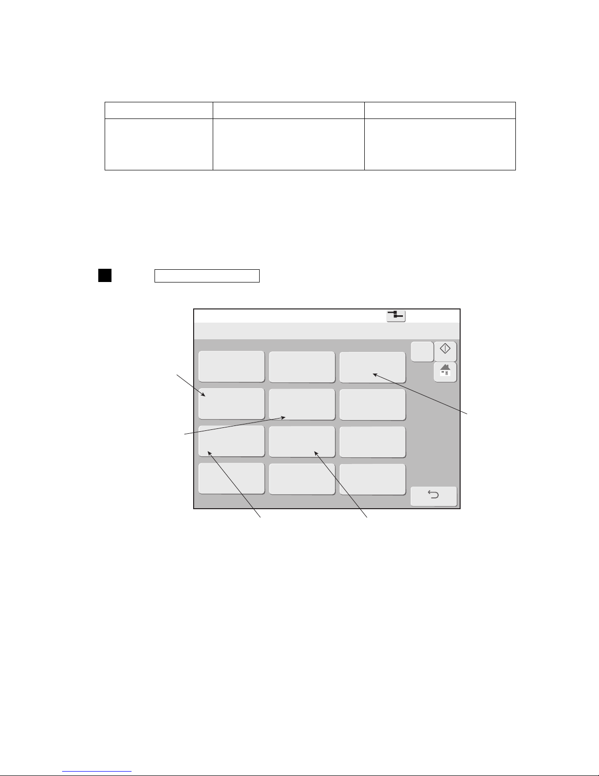
Sets whether or
not to select a
user which logs
in when power
is turned on.
Sets function
restrictions for
each user.
Sets the password.
Delete the user.
Create the new user.
Press Login management of the Environment setup menu.
The Login management menu is displayed.
1
Page 21
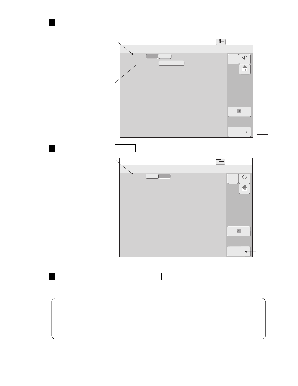
3-6 ●Selecting user when power is turned on
Using environment setup
2015.07.0712:45
Com=0
[Stop
]
Login method
Default login ID : 1
Admin
OK
Cancel
Disable
Enable
Startup
M
Manual
HOME
Specifies the login user
When "Disable" is selected,
the Print description screen
is immediately displayed
when the power is turned on.
OK
Using environment setup
2015.07.0712:45
Com=0
[Stop
]
OK
Cancel
Disable
Enable
Startup
M
Manual
HOME
When "Enable" is selected,
selects the user which logs
in when the power is turned
on.
OK
Login method
Press Using environment setup .
The Using environment setup screen is displayed.
2
Press Login method Enable .
3
Select the login method and press OK .
Sets whether or not to select a user which logs in when power is turned on.
4
When the Login method is "Enable", the Select login user screen is displayed when the power is turned
on. At this time, if the set password is forgotten, the program will not advance to the print description
screen. Set and manage the password carefully.
If you forget the password, consult your nearest local distributor.
CAUTION
Page 22
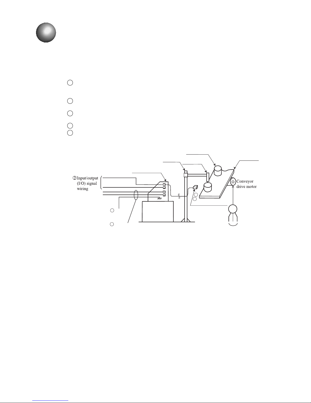
●Wiring precautions 4-1
Motorpowerline
M
Conveyor
Printtargetdetector
Printhead
Printtarget
Stand
Printstop
Ready
IJprinterbody
1Primarypowersource
5Ground
3
4
4.1 Wiring precautions
(1)If noise enters the IJ printer from the outside, there is the danger of erroneous operation or trouble.
To improve noise resistance, perform wiring work as follows:
Separate the power cable to the IJ printer from other power lines for powering use (especially, power
line for a speed control inverter, etc.).
Wiring the power cable through a separate duct is even better.
Do not bundle input/output (I/O) signal wiring together with other power lines. Wire them
independently instead.
Electrically isolate the print target detector, print head, stand, and IJ printer body from other
machinery and equipment (conveyor, etc.).
Separate the print target detector wiring from other power lines.
Perform that all electrical wiring, connections and grounding comply with applicable cords.
(When erroneous operation was caused by noise, etc., use a dedicated ground.)
4. ELECTRIC SIGNAL CONNECTION
1
2
3
4
5
(2) Connection to power supply
Use a suitable plug and always connect the power source to a protective ground. In addition, arrange the
receptacles near the IJ printer so that removal is easy.
Page 23
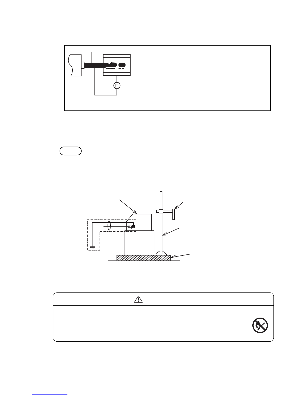
4-2 ●Wiring precautions
+++
+++
Signalground
Nozzle Inkcolumn
Chargeelectrode
Primarypowercable
Printheadunit
Stand(option)
Spacedbyinsulator
IJprinterbodyframe
Weldingworkcautions
E
(3) Precautions related to welding current of welder
Signal (weak electric) ground and frame ground are connected because the ink drops of the IJ printer
are electrically charged.
The ink drops are electrically charged by impressing a voltage between the charging electrode and ink column as
shown at the left.
Therefore, the ink always becomes signal ground.
In addition, since the ink is always connected to frame
ground by the clamp, etc. of the circulation path, separating
signal ground and frame ground is difficult.
Charge theory
Therefore, when a large current (for example, the welding current of a welder) flows from the
outside through frame ground, the current is also diverted to signal ground and the PC boards may
be damaged. For this reason, when performing welding work near the IJ printer, proceed as follows:
Method
Be sure to insulate the printhead and IJ printer frame to keep the welding current from flowing to
the control section of the printer, and to make a separate ground connection for the printer.
If this method is used, welding work becomes possible even while the IJ printer is operating.
●Fire is strictly forbidden around the IJ printer
The ink and makeup are both flammable. Welding sparks may cause ignition or a fire.
Take measures so that sparks do not enter the surrounding area whether or not the IJ
printer is operating, and ventilate sufficiently.
Just in case, ensure safety by installing a powder type fire extinguisher nearby.
WARNING
Page 24
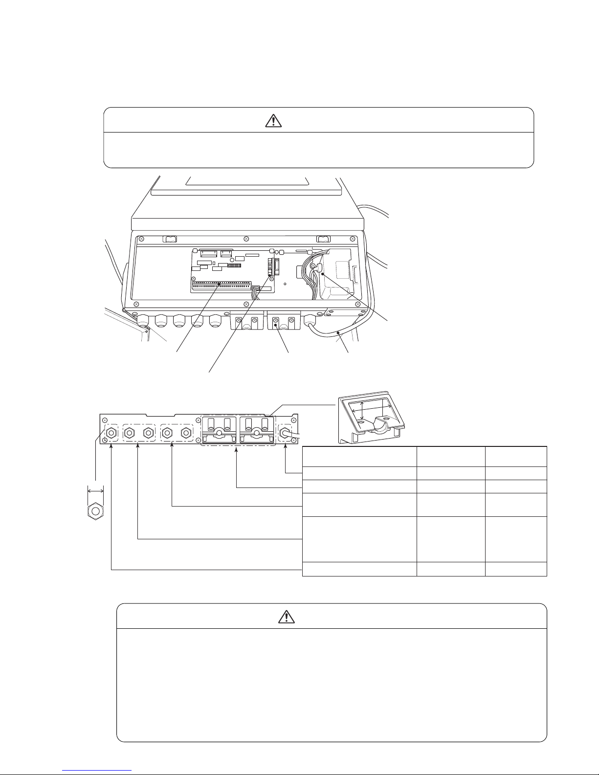
●Input/output (I/O) signal connection 4-3
Terminalblocks1
Lead-inPort
Separatecode
Communicationconnector(OptionalonRX-B)
Ethernetcommunicationconnector
(Option:Dependingonmodels)
Name
Forseparatecode
Forexternalcommunications
Forprinttargetdetector/
forencoder
Forreciprocativeprinting,
Print-in-progress,
Print.complete,printstop,
online,remotesignal
ForReady,Fault,Warning
φ4.5〜10(M16)
φ3.5〜10
φ3.5〜7(M12)
φ4.5〜10(M16)
φ4.5〜10(M16)
Cableoutside
diameterrange
[Lead-inport]
19(d)
38(W)×17(H)
15(d)
19(d)
19(d)
d
W
H
Size/Dimension
4.2 Input/output (I/O) signal connection
4.2.1 Wiring the I/O line
Open the top cover and run the I/O line wiring from the lead-in port on the side and connect it to external
connection terminal boards 1 and 2 and the external communications connector inside the IJ printer.
When performing wiring work, always turn off the power.
During normal use, leave the top cover closed.
CAUTION
Use cables with an outside diameter within the range specified above. Firmly tighten
the lead-in port lock nut.
In addition, do not bundle weak electric system and strong electric system cables
together inside and outside the IJ printer so that the weak electric system signals
(signals to terminal board 1 and external communication connector) are not affected by
strong electric system signals (power source).
Especially, absolutely never bundle together the print target detector and print stop
signals and the power source and Ready to print signal cable and do not wire them
inside the same duct.
CAUTION
Page 25
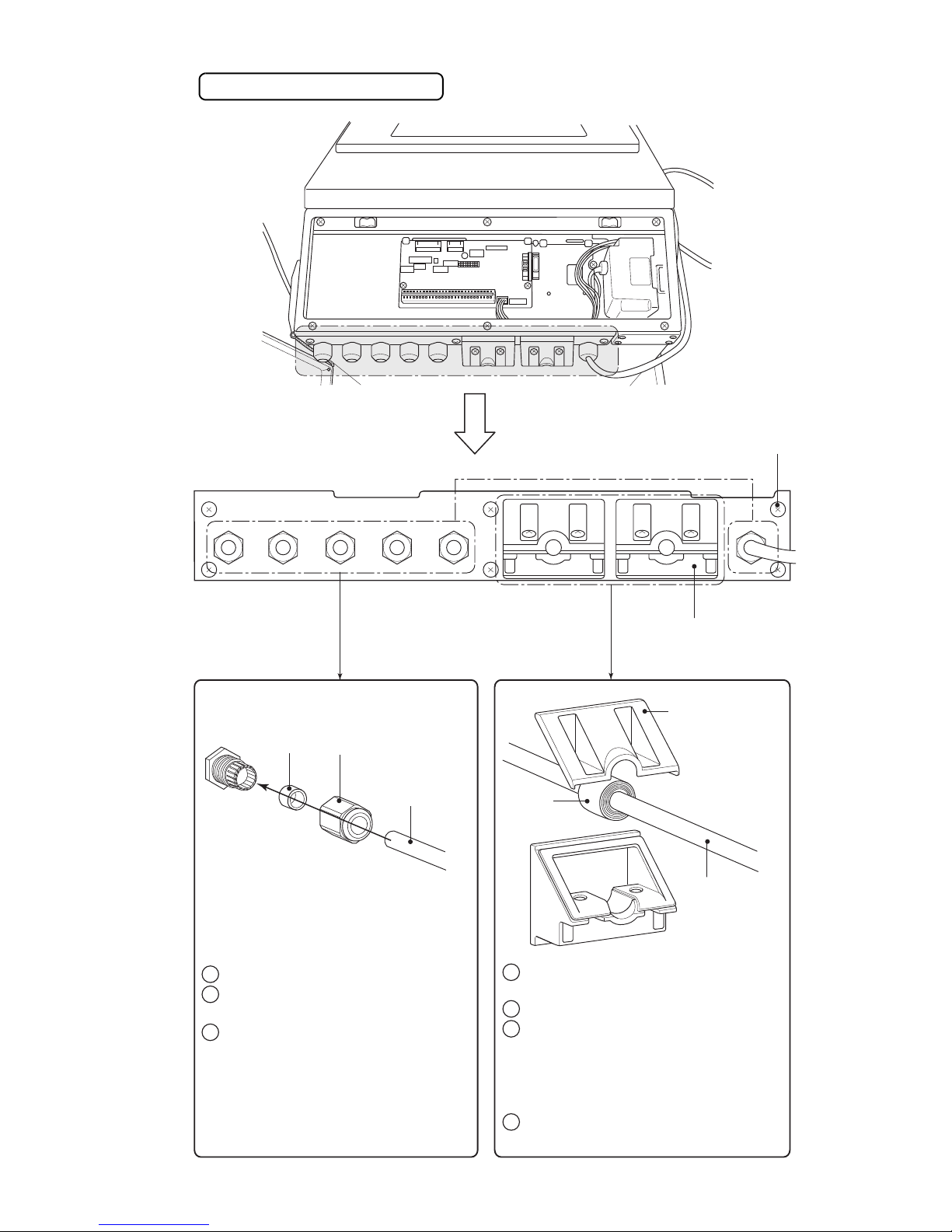
4-4 ●Input/output (I/O) signal connection
Cablesealblock
Setscrew
Locknut
Cablesealblock
Seal
Cable
[Lead-inport]
Removethesetscrewandremove
thecablesealblockfromthebody.
Separatethecablesealblock.
Wraptheoutsideofthecablewith
sealasshowninthefigure.
Wrapthesealsothatthereis
nogapbetweenitandthecable
sealblock.
Reassemblethecablesealblockby
followingtheoppositeprocedure.
1
2
3
4
(
)
Removethelocknut.
Passthecablethroughasshown
inthefigure.
Tightenthelocknut.
Tightenthelocknutsecurely
usingatool.
1
2
3
)(
Seal
Cable
Lead-in port connection method
Page 26
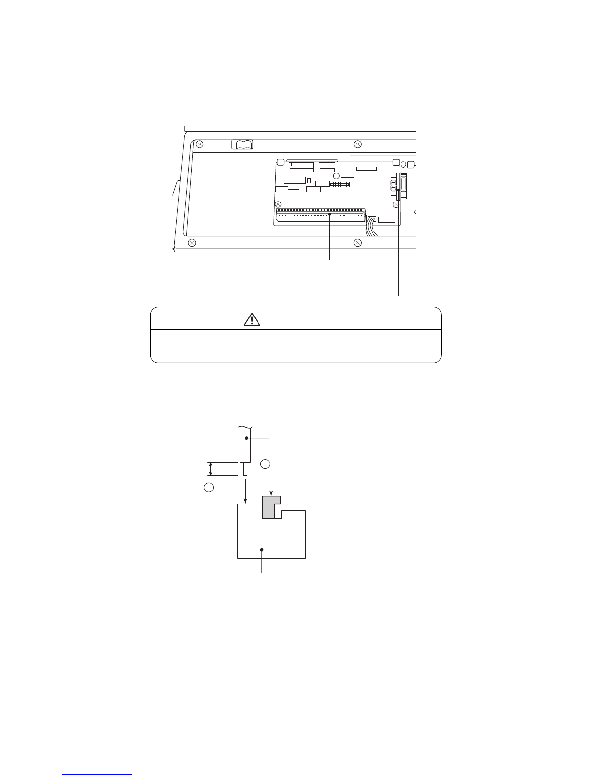
●Input/output (I/O) signal connection 4-5
4
Externalconnection
terminalblock1
TB1
Communicationconnector
Wire(Twistthewire.)
Press
Insert
Terminalblock
(TB1)
1
2
Stripped
4.2.2 Connection to input/output (I/O) terminals
[Overview of Terminals and Connectors]
The terminal blocks and connectors for wiring are located behind the electrical access door (upper
front panel door).
[Usage for the External connection terminal block 1 (TB1)]
● Applicable cable size : AWG26 to 18 (Φ0.4 to 1.0) (Note1)
● Wire covering to be stripped : 8 to 9 mm
(Note1)
Since the applicable wire size for terminal block TB1 has acquired UL approval with
AWG26 to 20, when using under conditions equivalent to UL Standards, use AWG26
to 20 wire.
Faulty wiring causes the substrate breakdown.
Before wiring, be sure to confirm the terminal signal.
CAUTION
Page 27
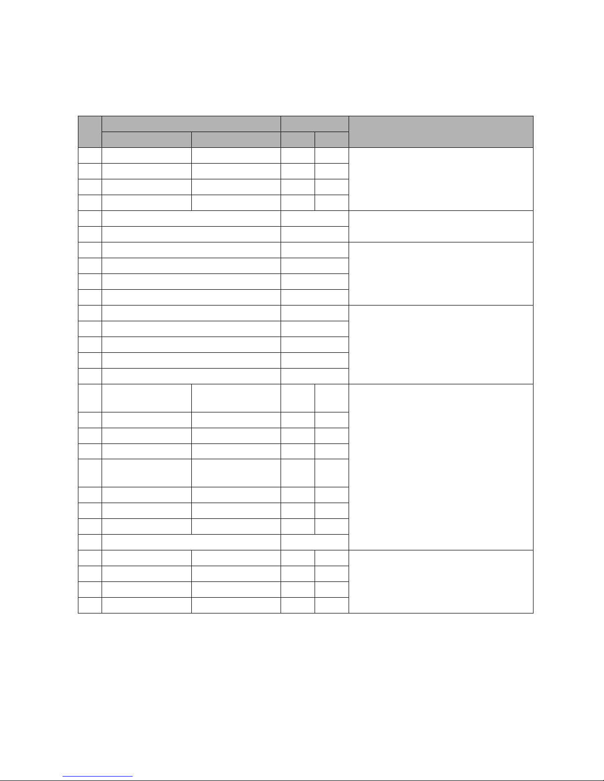
4-6 ●Input/output (I/O) signal connection
Pin
No.
Name Input/output
Remarks
NPN Interface PNP Interface NPN PNP
1 Power supply Print target detector Output Input
● DC24V, 100mA max. (*1)
● Power supply can be selected by SW1
● Connection pin number is different
between NPN and PNP interface.
2 Print target detector Ground Input -
3Ground NC - -
4 NC Power supply - Output
5 Print stop Input
● NPN / PNP can be selected by SW2
● RX-S: Standard, RX-B: Option
6 Signal ground -
7 Encoder power supply Output
● DC24V, 100mA max. (*1)
● Totem pole / Open collector (NPN) can
be selected by SW1
● Power supply can be selected by SW1
8 Encoder signal (Totem pole) Input
9 Encoder signal (Open collector NPN) Input
10 Encoder ground -
11 Deflection voltage ON/OFF signal Input
● NPN / PNP can be selected by SW2
● RX-S: Standard, RX-B: Option
12 Reciprocative print signal Input
13 Run signal Input
14 Reset signal Input
15 Stop signal Input
16
Print-in-progress/
Print-complete
-Output-
● Print-in-progress/ Print-complete can be
selected with screen operation.
● Connection pin number is different
between NPN and PNP interface.
NPN interface: No.16-19
PNP interface: No. 20-23
● RX-S: Standard, RX-B: Option
17 Online output - Output -
18 Universal output 1 - Output -
19 Universal output 2 - Output -
20 -
Print-in-progress/
Print-complete
-Output
21 - Online output - Output
22 - Universal output 1 - Output
23 - Universal output 2 - Output
24 Signal ground -
25 Ready - Output -
● Open collector (NPN) only
26 Signal ground - - -
27 Fault - Output -
28 Warning - Output -
[ Connection to the external connection terminal block (TB1 of EZJ110 P.W.B) ]
(*1): The supplying power capacity for print target detector and encoder is up to 100mA in total.
● The I/F signal with conveyer is connected.
● NPN/PNP interface can be selected for the print target detector and a part of I/O signals.
● Totem pole/Open collector(NPN) can be selected for the encoder signal.
● Pin #5, #6 and #11 to 24 --- RX-S:Standard, RX-B: Option
Page 28
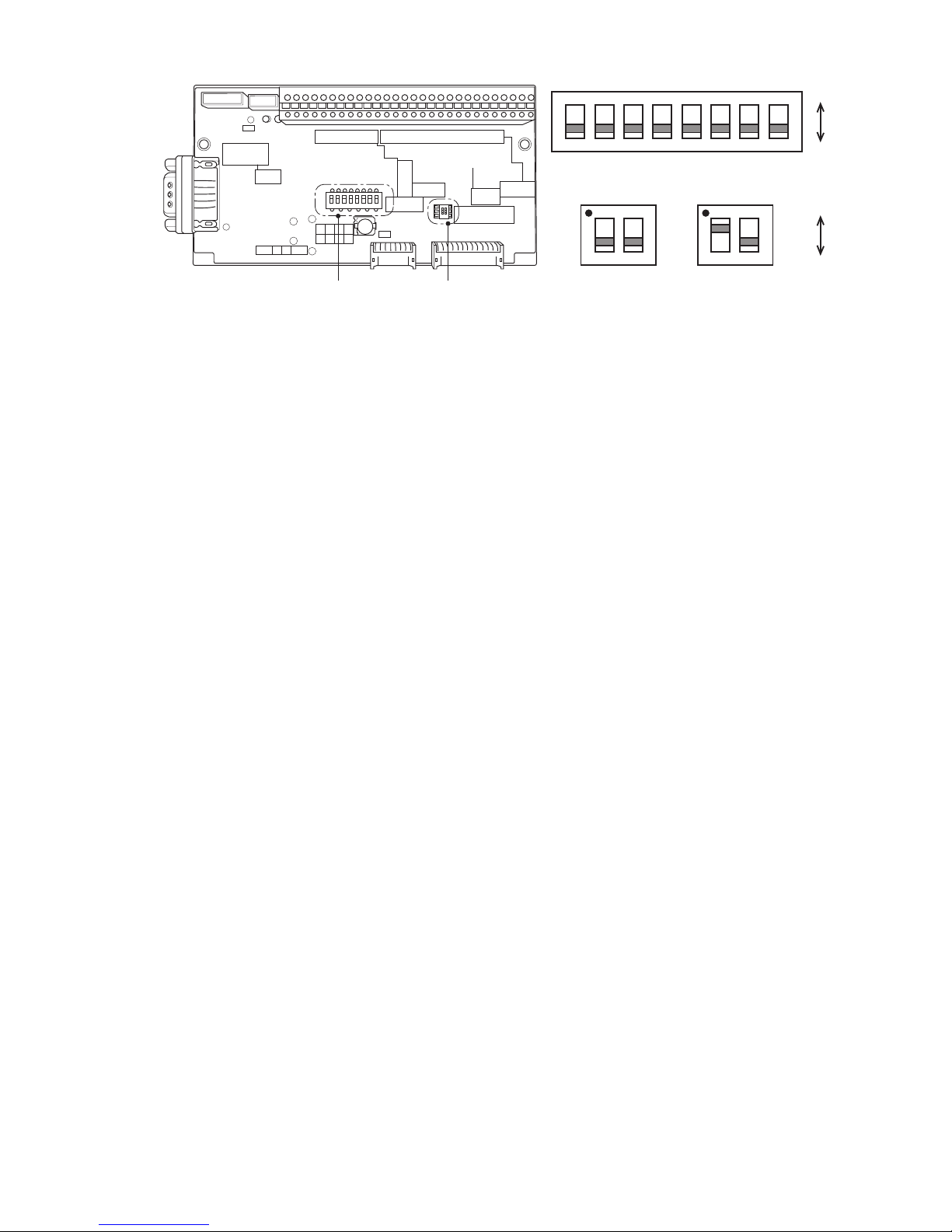
●Input/output (I/O) signal connection 4-7
SW1
EZJ110board
SW2
ON
1
ON
OFF
2 3 4 5 6 7 8
SW1
ON
OFF
SW2
NPN PNP
(Precautions when using combination of NPN/PNP interfaces)
● Use either NPN or PNP interface for input/output signals #5 to 6 and #11 to 24. Do not use a combination
of the interfaces for these input/output signals.
● Interfaces can be combined for units of print material sensor signals (#1 to 4), encoder signals (#7 to 10),
input/output signals (#5 to 6, #11 to 24) and status output signals (#25 to 28).
(For example, PNP interface can be used for print material sensor and NPN interface can be used for
status output signals (#25 to 28).
Page 29
4-8 ●Input/output (I/O) signal connection
4.3 Input/output (I/O) specifications
When handling external signals, observe the voltage, current, and time given in this manual.
Operation is not guaranteed if external signals are not handled properly.
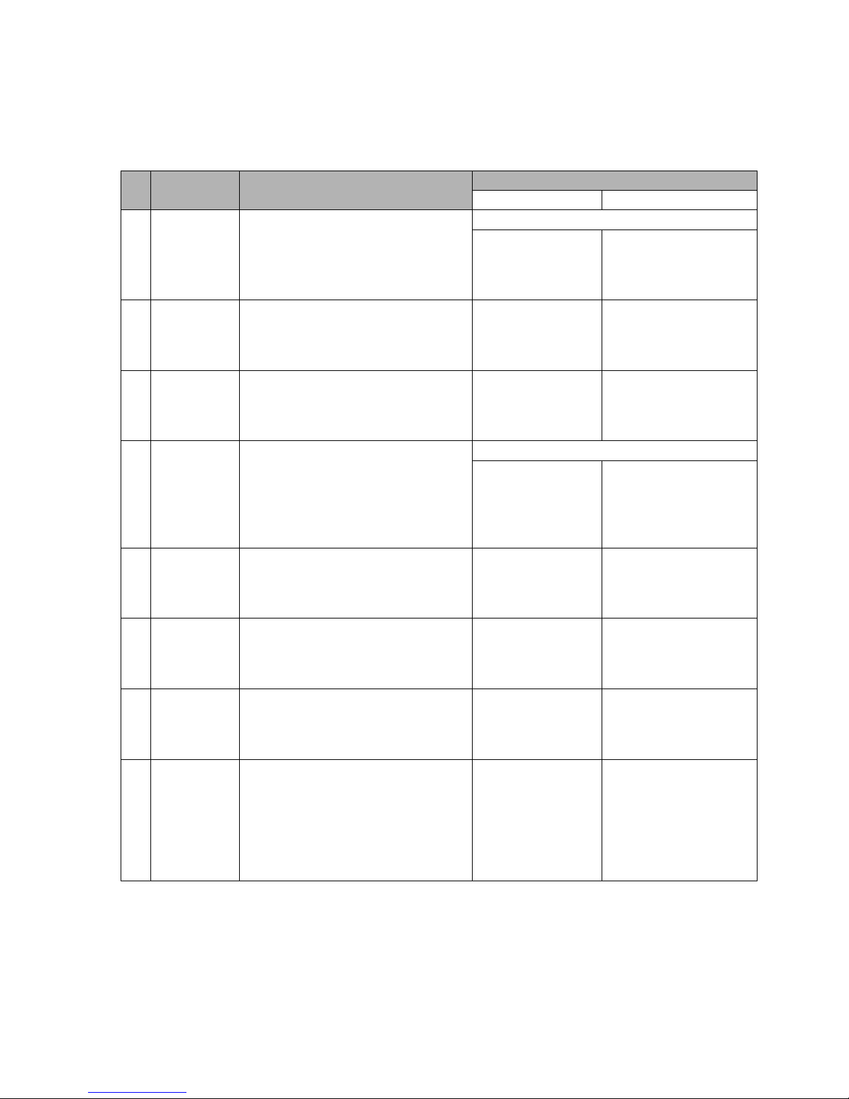
No. Signal name Function
Electrical characteristics
+NPN input PNP input
1
Print object
detection
Indicates the arrival of a print object.
+24 V output (Up to 100mA *1)
ON state :
I out : 12 mA max.;
OFF state:
Vout : 24 V *3)
ON state :
I in(at24V): 12 mA max.
OFF state:
V in: 1V max. *3)
2 Printing stop
Issues instructions so that printing does
not start even if a print object is
detected.
ON state :
I out : 6 mA max.;
OFF state:
Vout : 24 V *3)
ON state :
I in(at24V): 6 mA max.
OFF state:
V in: 1V max. *3)
3
Reciprocative
printing
Issues instructions so as to change the
order of characters to be printed.
OFF:Transport in normal direction
ON :Transport in reverse direction
ON state :
I out : 6 mA max.;
OFF state:
Vout : 24 V *3)
ON state :
I in(at24V): 6 mA max.
OFF state:
V in: 1V max. *3)
4
Encoder
(for speed
follow-up)
Makes a pulse entry in proportion to the
print object transport speed.
+24 V output (Up to 100mA *1)
NPN open collector
ON state :
I out : 20mA max.;
OFF state:
Vout : 24 V *3)
Totem pole
ON state :
I in(at24V): 20mA max.
OFF state:
V in: 1V max. *3)
5 Run *2)
Functionally the same as the RUN key
on the operator panel.
Performs processing from "ink
injection" to "ready to print"
ON state :
I out : 6 mA max.;
OFF state:
Vout : 24 V *3)
ON state :
I in(at24V): 6 mA max.
OFF state:
V in: 1V max. *3)
6 Reset
Functionally the same as the Reset key
and the Message Delete key on the
Error Message window.
Resets an error.
ON state :
I out : 6 mA max.;
OFF state:
Vout : 24 V *3)
ON state :
I in(at24V): 6 mA max.
OFF state:
V in: 1V max. *3)
7Stop
Functionally the same as the STOP key
on the operator panel.
Stops injection of ink (automatic
flushing).
ON state :
I out : 6 mA max.;
OFF state:
Vout : 24 V *3)
ON state :
I in(at24V): 6 mA max.
OFF state:
V in: 1V max. *3)
8
High voltage
ON/OFF
Functionally the same as the Deflection
Voltage Control function in a message
which appears when the CONTROL
key on the operator panel is pressed.
The deflection voltage is turned on
(Ready) and off (Standby) alternately
each time this signal is entered.
ON state :
I out : 6 mA max.;
OFF state:
Vout : 24 V *3)
ON state :
I in(at24V): 6 mA max.
OFF state:
V in: 1V max. *3)
[Input / Output Signal Specifications]
(1) Input signals (external device →IJ printer)
*1) The current supply capacity of +24V for Print object detector and encoder is up to 100mA in total.
*2) RUN signal instructs to inkjet ink. Handle the signal with care.
*3) Ensure that the external device transistor leak current doesn't exceed 0.1mA while the input signal is OFF.
Page 30
●Input/output (I/O) signal connection 4-9
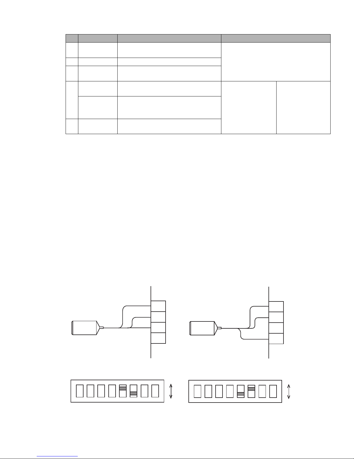
No. Signal name Function Electrical characteristics
1Ready
Operates when the IJ printer is ready for
printing or in input mode.
Open collector (NPN)
● Sink current: 20 mA max.
● ON voltage: 0.5 V or less
● Operating voltage: 30 V or less
2 Fault Operates when the IJ printer is fault state.
3Warning
Operates when the IJ printer is in alarm
condition.
4
Print. in
Progress *4)
Operates when the IJ printer is engaged in
printing.
Open collector (NPN)
● ON voltage:
0.5 V or less
● Sink current:
20 mA max.
● Operating voltage:
30 V or less
Open collector (PNP)
● I in: 10 mA max.
(Load resister:
2.2kΩ or more)
● ON voltage: +24V
Print.
Completed *4)
Operates when the IJ printer completes a
printing process
(outputs a pulse of up to 1 second).
5 Online output
Operates when the IJ printer is in online
mode
(2) Output signals (IJ printer →external device)
*4): As regards "Print. in progress" and "Print. completed", one must be selected from a screen.
Printtargetdetector
TB1
DC24V
Signal
GND
Power
Signal
GND
1
2
NC4
3
・SW1"5":ON
・SW1"6":OFF
ON
1
SW1setting
ON
OFF
2 3 4 5 6 7 8
Printtargetdetector
TB1
Signal
GND
NC
Power
Signal
GND
1
2
DC24V4
3
・SW1"5":OFF
・SW2"6":ON
ON
1
SW1setting
ON
OFF
2 3 4 5 6 7 8
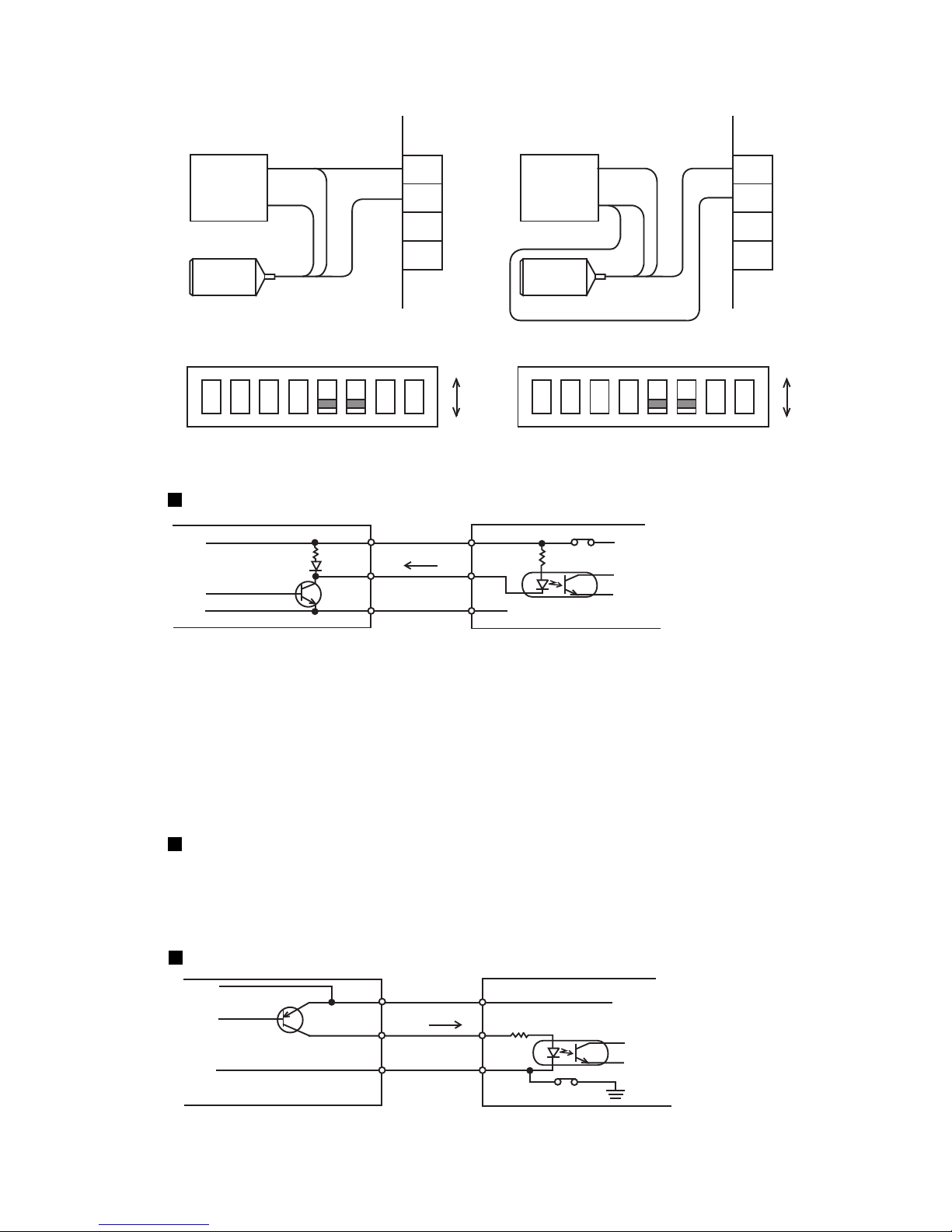
4.3.1 Print target detector input
This function inputs the IJ printer print start signal.
Use a no-contact (transistor) type print target detector. An optoelectronic sensor with built-in amplifier
which uses a light beam to detect the print target is ideal. When the total current consumption of the print
target detector and the rotary encoder is 100mA or less, power can be supplied from the power supply
built into the IJ printer. When the total current consumption exceeds 100mA, provide a dedicated power
supply.
In this case, perform wiring and setting as described below.
(1) Print target detector connection method
(a) When NPN interface and IJ printer built-in
power supply are used
(b) When PNP interface and IJ printer built-in
power supply are used
Page 31
4-10 ●Input/output (I/O) specifications
Printtargetdetector
TB1
DC24V
Signal
NC
Power
Signal
GND
1
2
NC4
3
・SW1"5":OFF
・SW1"6":OFF
ON
1
SW1setting
ON
OFF
2 3 4 5 6 7 8
DC24V
GND
24VDCdedicated
powersupply
Printtargetdetector
TB1
Signal
GND
NC
Power
Signal
GND
1
2
NC4
3
・SW1"5":OFF
・SW1"6":OFF
ON
1
SW1setting
ON
OFF
2 3 4 5 6 7 8
DC24V
GND
24VDCdedicated
powersupply
Tr
GND
DC24V
Power
Signal
4
1
2
SW1-6
Printtargetdetector IJprinter
IL
(c) When NPN interface and dedicated power
supply are used
(d) When PNP interface and dedicated power
supply are used
GND
Tr
GND
DC24V
DC24V
Signal
1
2
3
SW1-5
Printtargetdetector IJprinter
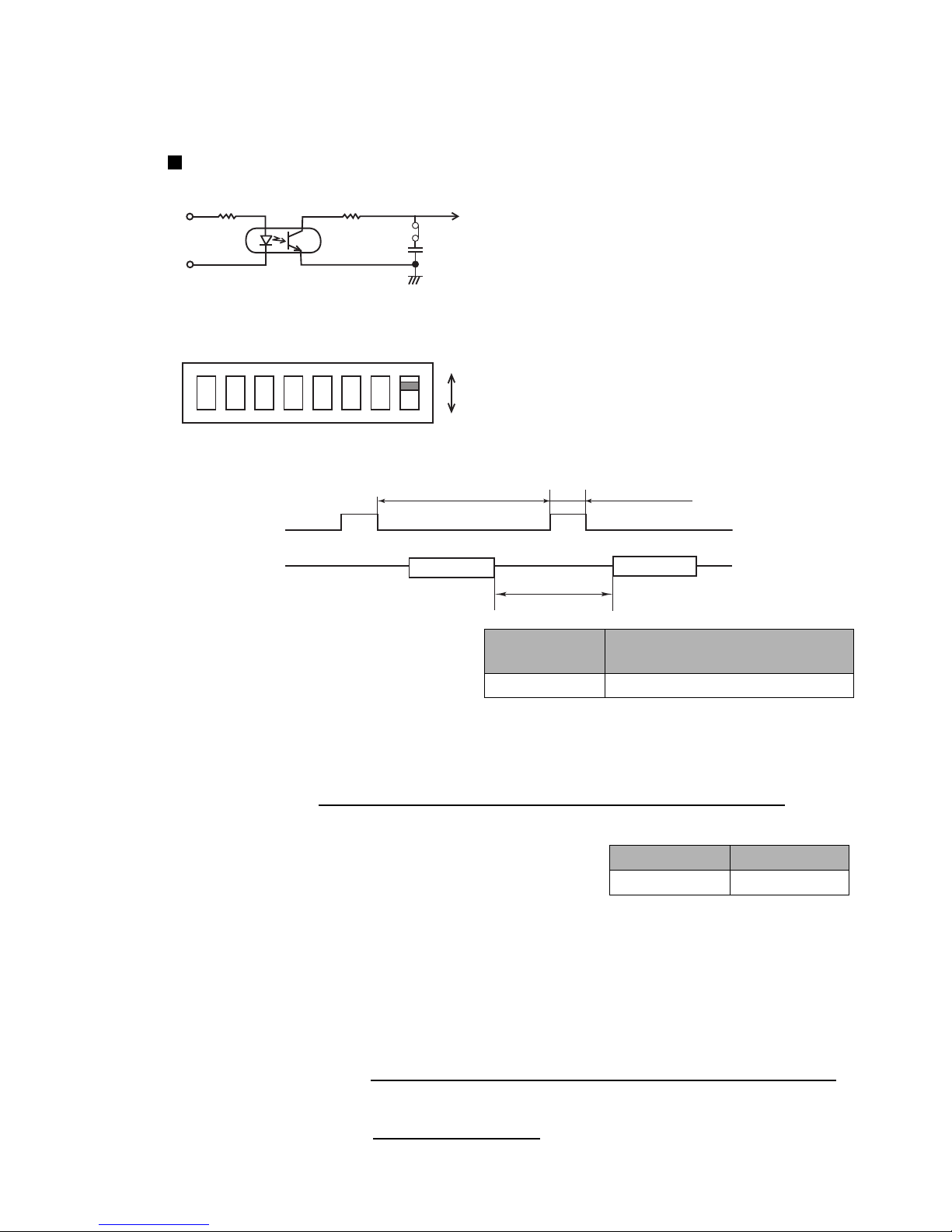
(2) Print target detector specifications
(a) When NPN interface is used
Internal circuit diagram
When the IJ printer input circuit is a current drive load for the print target detector output circuit and
output transistor Tr of the print target detector is ON, it becomes the print start signal input.
Use an output transistor Tr which satisfies the following specifications (NPN/PNP):
Withstand voltage : 24VDC or greater
Maximum drive current : 12mA or greater (IL= 10mA)
Residual voltage : 2V or less
Leakage current : 0.1mA or less
The IJ printer built-in power supply specifications are:
Power supply voltage : 24V
Maximum supply current : 100mA *Note 1
*Note 1: Total power supply to print target detector and rotary encoder is max. 100mA
(b) When PNP interface is used
Internal circuit diagram
.
.
Page 32
●Input/output (I/O) specifications 4-11
1kΩ
SW1-8
2.2μF
・SW1"8"ON:FilterON
OFF:FilterOFF
ON
1
SW1setting
ON
OFF
2 3 4 5 6 7 8
Timeconstantt=2.2msec
(3) Print target detector signal noise filter setting
This function uses to filter the normal noise generated at the print target detector signal and noise generated
by water drops, etc. with CR.
The target sensor filter function (See “Instruction manual 4.14 Set the print specifications”) is effective
against sensor chattering.
Internal circuit diagram
Printing
Printing
3msmin. 3msmin.
OFF
ON
*Printingpreparation
time
(Printstartdelay
adjustment=0)
Printobject
detectionsignal
Printingoperation
(Printinginterval)
(4) Relationship between print object detection signal and printing operation
*: The printing preparation time minimum
value varies with the print dot matrix, ink
drop use, etc., however, the right table can
be used as a reference.
Nozzle size
Reference of printing preparation
time minimum value
65µm 9 ms
The accurate printing preparation time can be calculated by following formula.
Necessary printing preparation time (Note 1) = [(One scan time) x (N + 1) ] (ms)
(One scan time) =
(Number of vertical dots + Character width) x Ink drop use percentage
Excitation frequency (kHz)
(ms)
N : (One scan time x N) Remaining number that is set to "a"
(a: Refer to the right table.)
Excitation frequency: 75.4 (Model RX, with 65µm nozzle and JP-K69 ink)
>
=
Nozzle size a
65µm 5.5
(Note 1) Time for repeated printing of fixed characters. When using the communications function or
2-dimensional bar code function, it will be longer than the time calculated from this formula.
When the speed is followed up, the number of encoder pulses shown below will serve as reference for the
minimal value of print space:
Excitation frequency (kHz)
(ms)
Minimal time of 1 pulse =
(Number of vertical dots + Character width) x Ink drop use percentage
Number of necessary
a
Minimal time of 1 pulse
Frequency division setting value (pulse)
+
encoder pulses
=
Page 33
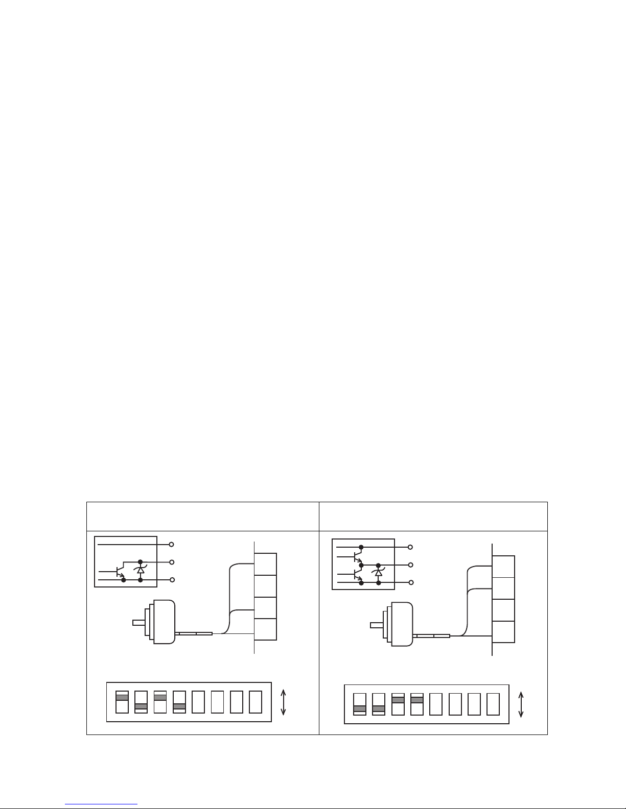
4-12 ●Input/output (I/O) specifications
(a) When open collector output and IJ printer built-in
power supply are used
(b) When totem pole output and IJ printer built-in
power supply are used
ON
1
SW1setting
ON
OFF
2 3 4 5 6 7 8
7
8
9
10
TB1
24V
Signal
GND
24V
Signal
GND
Rotaryencoder
ON
1
SW1setting
ON
OFF
2 3 4 5 6 7 8
7
8
9
10
TB1
24V
Signal
GND
24V
Signal
GND
Rotaryencoder
24V
Signal
GND
4.3.2 Product speed matching function using a rotary encoder
The product speed matching function is used when the speed of the print target or the conveyer carrying the
print target changes while the IJ printer is printing. If this function is not used, when the speed changes, the
width of the printed characters may change and the characters may be difficult to read.
When the product speed matching function is used, it is necessary to input an external electric pulse having a
period proportional to the speed to the IJ printer. Ordinarily a rotary encoder is used for this purpose. The IJ
printer can print each vertical line of the printed message in synchronization with the pulses from the rotary
encoder.
4.3.2-1 Rotary encoder specifications wiring and switch setting
(1) The specifications of the connectable rotary encoders are:
Output waveform : Square wave (duty: 30to 70%)
Output withstand voltage : 24VDC or greater
Load current : 20mA or greater
Leakage current : 0.1mA or less
Power supply voltage : 24VDC
Current consumption : 100mA or less *Note 1
(When the IJ printer built-in power supply is used, the total current
consumption with the detectors is 100mA or less.)
Input signal frequency : 200kHz or less
Number of pulses : Decided by production line conditions
*Note 1) The maximum power supply capacity of the IJ printer built-in power supply (24VDC) is
100mA. When the current consumption of the detector and encoder exceeds 100mA and the
power supply voltage is outside 24V, use a dedicated power supply and perform the wiring
work described in (3) below.
(2) Encoder wiring and setting of SW1 on PC board EZJ110 when IJ printer built-in power supply is used
(5) Tracking function
● This function achieves printing even when two or more print objects are positioned between the print
object detector and print head.
● Up to four print objects can be positioned between the print object detector and print head.
● This function cannot be exercised simultaneously with the repeat-printing function.
Page 34
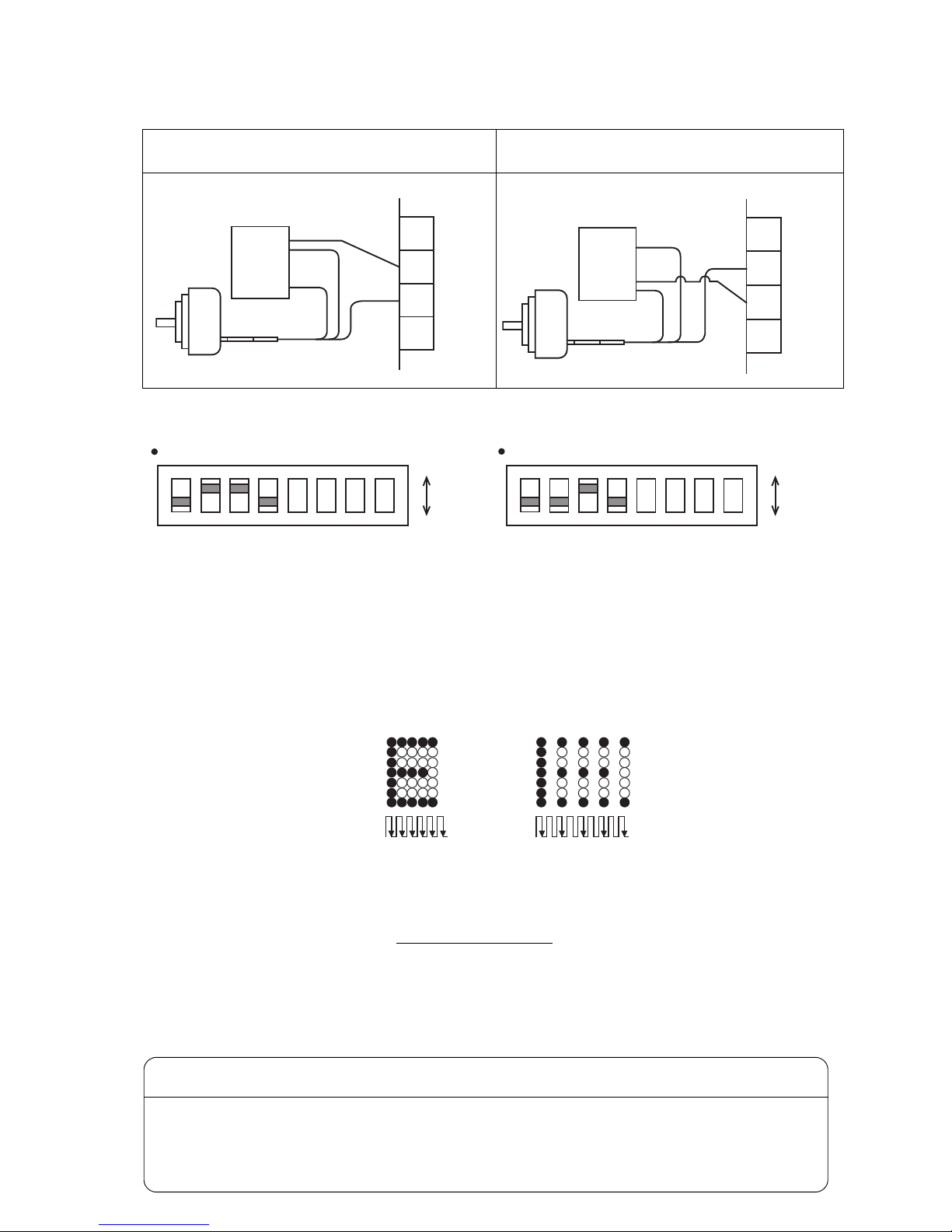
●Input/output (I/O) specifications 4-13
ON
1
SW1setting(for12Vdedicatedpowersupply)
ON
OFF
2 3 4 5 6 7 8
*Foropencollectoroutputandtotempoleoutput
ON
1
SW1setting(for24Vdedicatedpowersupply)
ON
OFF
2 3 4 5 6 7 8
*Foropencollectoroutputandtotempoleoutput
(c) When open collector output and dedicated power
supply are used
(d) When totem pole output and dedicated power
supply are used
Signal
Signal
Rotaryencoder
DCdedicatedpowersupply
(+12V,+24V)
7
8
9
10
TB1
GND
GND
GND
+V
+V
GND
Signal
Signal
Rotaryencoder
DCdedicatedpowersupply
(+12V,+24V)
7
8
9
10
TB1
GND
+V
GND
+V
+V
GND
(Whendivisionfactor:001)
Pulsesfromencoder
(Whendivisionfactor:002)
(3) Encoder wiring and setting of SW1 on EZJ110 PC board when used with a dedicated power supply
● Wiring used for a dedicated power supply differs according to output interface of the encoder, but can be the same
depending on power supply voltage.
4.3.2-2 Setting to IJ printer
(1) Make the settings related to “Product speed matching” and “Pulse rate div. factor” at the “Print specifications”
screen. (See “Instruction manual 4.14 Set the print specifications”.)
●Set “Product speed matching” to “1: Enable”.
●Set “Pulse rate div. factor” as required. This function lowers (makes the period longer) the frequency of the
input pulses inside the IJ printer. The divided pulses become the pulses used in printing.
<Description of pulse division function>
●The rotary encoder signal pulse frequency, the print scan frequency and the division factor have the
relationship shown in (Eq. 1).
Encoder pulse frequency [kHz] =
Print scan count [kHz]
Division factor (l/n)
----(Eq. 1)
●Set “Speed compensation” at the “Print specifications” screen to “Enable”, as required.
<What is “Speed compensation”?>
This function reduces changes in the print start delay when the conveyer speed changes.
This function cannot be used when the product speed matching function is not used.
In addition, this function cannot be used when “Repeat print” mode is set at the “Print specifications”
screen.
When “Speed compensation” is enabled, print start is delayed for 30 scans.
● Switch setting for a dedicated power supply differs according to power supply voltage, but can be the same
depending on output interface of the encoder.
CAUTION
Page 35
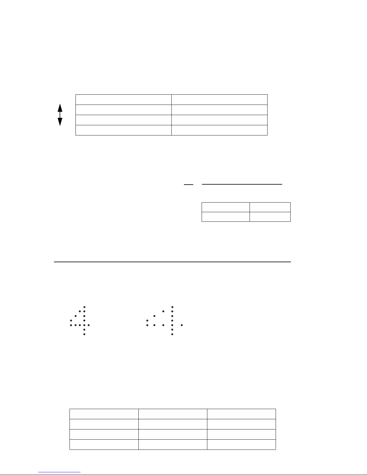
4-14 ●Input/output (I/O) specifications
(Number of vertical dots + character width set value +1) × (Denominator of ink drop use (*1))
Normal Characterwidthlarge
4.3.2-3 Method of calculating the conditions which allow product speed
matching
Calculate to find whether the Ink drop use and division factor are the conditions which allow product speed
matching, based on the following.
Print quality improves as the calculation shown below is performed and the Ink drop use becomes smaller.
In addition, when changing Ink drop use, check the print quality.
(1) Set the Character width on the "Print specifications" as below depending on the Ink drop use.
Ink drop use Character width set value
1/1 002
1/2 001
1/3 to 1/16 000
(2) The maximum print scan frequency is found from the following equation by means of the printed character
width and highest conveyer speed. Substitute the value according to the nozzle diameter of the type used at d.
1
60
×
Nozzle diameter d
65μm0.33
(3) Next, use (Eq. 3) to check if the maximum print scan frequency found from (Eq. 2) can be matched at IJ
printer set print speed.
>
● When the result of (Eq. 3) is smaller than the maximum print scan frequency (Eq. 2), product speed
matching is not performed normally and the character width becomes large.
Max. number of print scans [kHz] =
Highest conveyer speed [m/min]×
Number of horizontal dots -1
Print length [mm]-d[mm]
------(Eq. 2)
Excitation frequency (f)
[kHz] (Eq. 3)
Max. number of print scans [kHz]
●In addition, when “Product speed matching error” warning is set, a warning is generated.
In this case, (1) lower the conveyer speed, (2) widen the print character width, or (3) set Ink drop use
larger, so that the maximum print scan frequency becomes smaller than the calculated value of (Eq. 3).
(Makes the IJ printer set print speed faster than the highest conveyer speed.)
(4) The excitation frequency (f) in (Eq. 3) depends on the type of ink used. The excitation frequency by
typical nozzle diameter and ink is shown below. For other inks, refer to the handling guidance of each ink.
Nozzle diameter Type of ink Excitation frequency (f)
65μm JP-K67 75.4 kHz
65μm JP-K33 75.4 kHz
65μm JP-K69 75.4 kHz
Large
Small
(*1) The value is 3 when the ink drop use
is 1/3.
Page 36
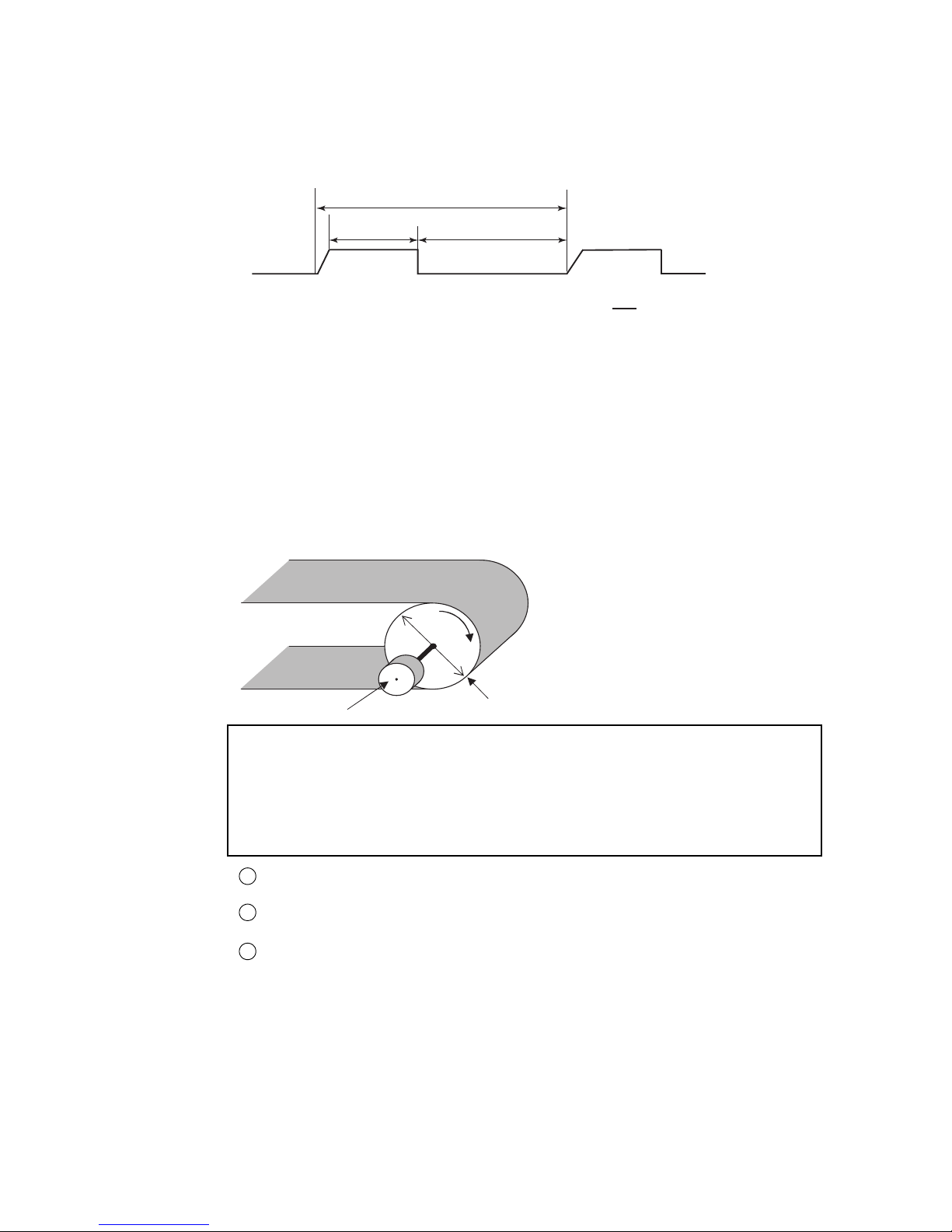
●Input/output (I/O) specifications 4-15
t15μsmin.(f=200kHzmax)
t2
OFF
ON
Duty
t2
t1
×100%
=
Seethatthedutyisbetween30%and70%.
Encodersignal
t32μsmin.
ON
Flatperiodofencodersignal(t3):2μsmin.
Encoder
Diameter
Conveyor
(5) When a rotary encoder is used, the print character width cannot be changed by changing the IJ printer character
width set value.
When the print character width must be changed, a device (timing belt, pulley, etc.) which varies the conveyer
speed and rotary encoder speed synch signal pulse frequency ratio must be installed.
(6) Restriction of the speed synchronization signal pulse frequency from the rotary encoder
(7) Rotary encoder selection method and calculation method
The print character width when the product speed matching function is used is determined by the amount of
movement of the product per encoder pulse.
Several examples are introduced below.
Example 1: Calculate the resolution of the rotary encoder when the rotary encoder is connected directly to the
conveyer shaft.
<Calculation conditions>
●Dot font : 5x7 dots (horizontal direction 5, vertical direction 7)
●Inter-character space : 1 dot (1 scan)
●Inter-character interval : 1.8mm [horizontal direction 6 dots (6 scans)]
(Inter-character dots 5 + inter-characters space 1)
●Diameter of conveyer pulley : 60mm
Distance the conveyer moves per 1 revolution of the rotary encoder
60mmx3.14=188.4mm/rev
Number of scans which must be executed while the conveyer is moving 1mm
6 scans/1.8mm=3.33 scans/mm
Required resolution of the rotary encoder (number of output pulses per 1 revolution of
the rotary encoder)
188.4mm/rev x 3.33 scans/mm=628PPR ( 2500PPR, Division factor=4)
1
2
3
=
.
.
Arrange for encoder signal cycle time (t1) to be at least 5 μs.
Page 37
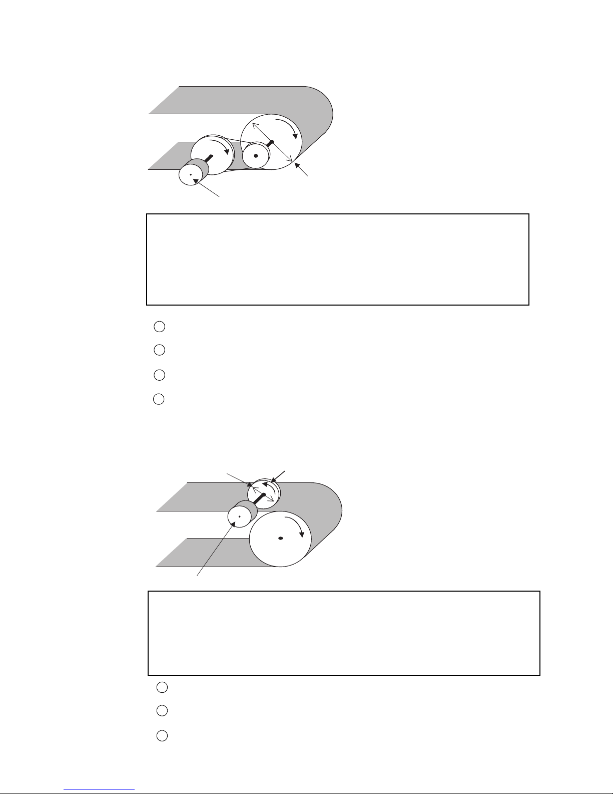
4-16 ●Input/output (I/O) specifications
PulleyB
Encoder
Conveyer
Diameter
PulleyA
Example 2: Calculate the diameter ratio (RT) of the pulley when the rotary encoder is connected to the
conveyer through a pair of pulleys.
<Calculation conditions>
●Dot font : 5x7 dots (horizontal direction 5, vertical direction 7)
●Inter-character space : 1 dot (1 scan)
●Inter-character interval : 1.8mm [horizontal direction 6 dots (6 scans)]
(inter-character dots 5 + inter-character space 1)
●Diameter of conveyer pulley : 60mm
●Resolution of rotary encoder : 1.000PPR
Amount of movement of conveyer per 1 revolution of rotary encoder
60mm x 3.14=188.4mm/rev
Number of scans which must be executed while conveyer moves 1mm
6 scans/1.8mm=3.33 scans/mm
Necessary number of output pulses (resolution) from rotary encoder
188.4mm/rev x 3.33 scans/mm=628PPR
Diameter ratio (RT) of pulley
RT=Diameter of pulley B/diameter of pulley A=1,000PPR/628PPR=Approx. 1.6/1
1
2
3
4
Pulley
Diameter
Encoder
Conveyer
Example 3: Calculate the necessary rotary encoder resolution when a pulley is installed to the shaft of the
rotary encoder and this pulley is connected to the conveyer.
<Calculation conditions>
●Dot font : 5x7 dots (horizontal direction 5, vertical direction 7)
●Inter-character space : 1 dot (1 scan)
●Inter-character interval : 1.8mm [horizontal direction 6 dots (6 scans)]
(Inter-character dots 5 + inter-character space 1)
●Diameter of rotary encoder pulley : 95.5mm
Amount of movement of conveyer per 1 revolution of rotary encoder
95.5mm x 3.14=300mm/rev
Number of scans which must be executed while the conveyer is moving 1mm
6 scans/1.8mm=3.33 scans/mm
Necessary number of output pulses (resolution) from rotary encoder
300mm/rev x 3.33 scans/mm=1,000PPR
1
2
3
Page 38
●Input/output (I/O) specifications 4-17
5
11
12
13
15
6
14
Printstop
Deflectionvoltage
control
Reciprocativeprint
Startup
Reset
Shutdown
GND
NPNinterfaceinput
specifications
24V
*Othersignalsare
alsothesame.
4.7kΩ
IJprinter
5
11
12
13
15
6
14
Printstop
Deflectionvoltagecontrol
Reciprocativeprint
Startup
Reset
Shutdown
GND
PNPinterfaceinput
specifications
24V
*Othersignalsare
alsothesame.
4.7kΩ
IJprinter
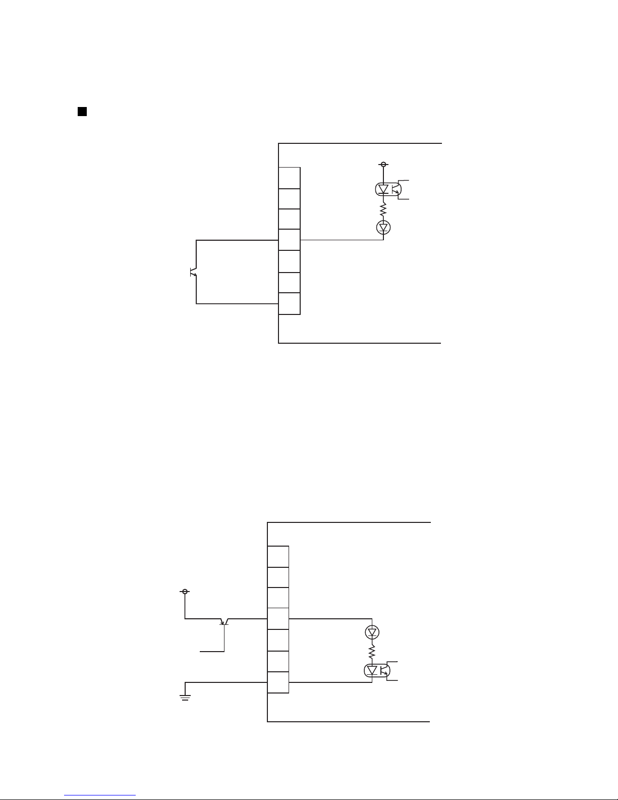
4.3.3 Input function
The IJ printer can be controlled by inputting print stop, remote operation (“Startup”, “Shutdown”, “Reset”,
“Deflection voltage control”) and reciprocative print switching to pins 5, 6, and 11 to 15 of TB1 by switch or
contact signal from the outside.
Internal circuit diagram
(a) NPN interface input (no voltage input)
●No-contact signal (transistor)
Withstand voltage : 30VDC or greater
Maximum drive current : 6mA or greater
Residual voltage : 2V or less
Leakage current : 0.1mA or less
Drive method : Open collector
●Contact signal
Use a relay whose contacts chattering at contacts ON/OFF is 2.0ms or less.
●Each input is activated when contact ON.
(b) PNP interface input (voltage input)
●Impressed voltage 24 to 30V
●Each input is activated when contact ON.
Page 39
4-18 ●Input/output (I/O) specifications
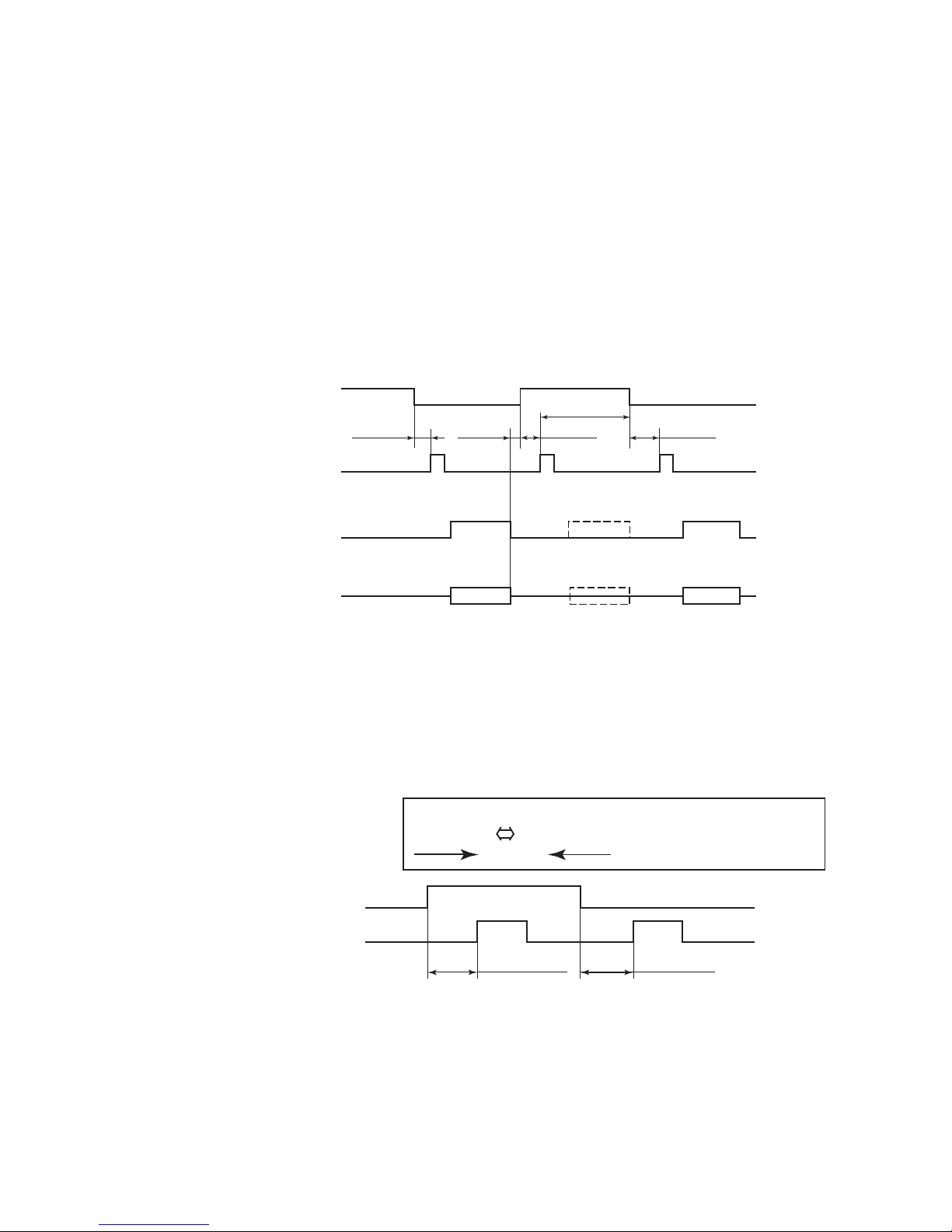
4.3.3-2 Reciprocative print signal input
[Function] This function switches the order of the characters to be printed.
Input OFF : Forward direction
Input ON : Reverse direction
●Regarding the signal levels, the ON state indicates low level and the OFF state indicates high level.
●The tracking function cannot be used.
In the tracking mode, the timing which stops printing by print stop signal cannot be specified.
●When Repeat print is set, the IJ printer is controlled by a print start signal generated internally.
*When the user environment setup item "Change Character Orientation" was set to "Reverse direction
printing", provide a minimum interval of 100ms up to input of the print target detector signal after
changeover (ON→OFF, OFF→ON) of the reciprocative printing signal.
When the Change Character Orientation was set to "normal or inverted" or "Character orientation 0 or
3", provide a minimum interval of 400ms up to input of the print target detector signal after signal
changeover.
Printstopsignal
ON
OFF
50msorgreater
0msor
greater
OFF
OFF
Printing
ON
ON
50msorgreater
20msorgreater
50msorgreater
Printing
[Noprinting]
Printtargetdetector
Printing-in-progresssignal
Printingoperation
4.3.3-1 Print stop signal input
[Function] This function prevents printing from the outside. (Note that the Ready to print output signal does not
change even if this signal is input from the outside.)
Input ON - In the IJ printer Ready to print state, the printer does not print even if the product target
detector is turned ON. However, the product being printed cannot be aborted.
Input OFF - In the IJ printer Ready to print state, the printer prints when the product target detector is
turned ON.
(Example)
●No-contact (transistor)
Withstand voltage : 30VDC or greater
Maximum drive current : 6mA or greater
Residual voltage : 2V or less
Leakage current : 0.1mA or less
Drive method : Open collector
●
Contact signal
Use a relay whose contacts chattering at contacts ON/OFF is 2.0ms or less.
123 123 (Thearrowindicates
thesequenceofprinting.)
WhenOFF WhenON
OFF
OFF
ON
ON ON
Min.100ms
Min.100ms
Reciprocativeprintsignal
Producttargetdetectionsignal
Page 40
●Input/output (I/O) specifications 4-19
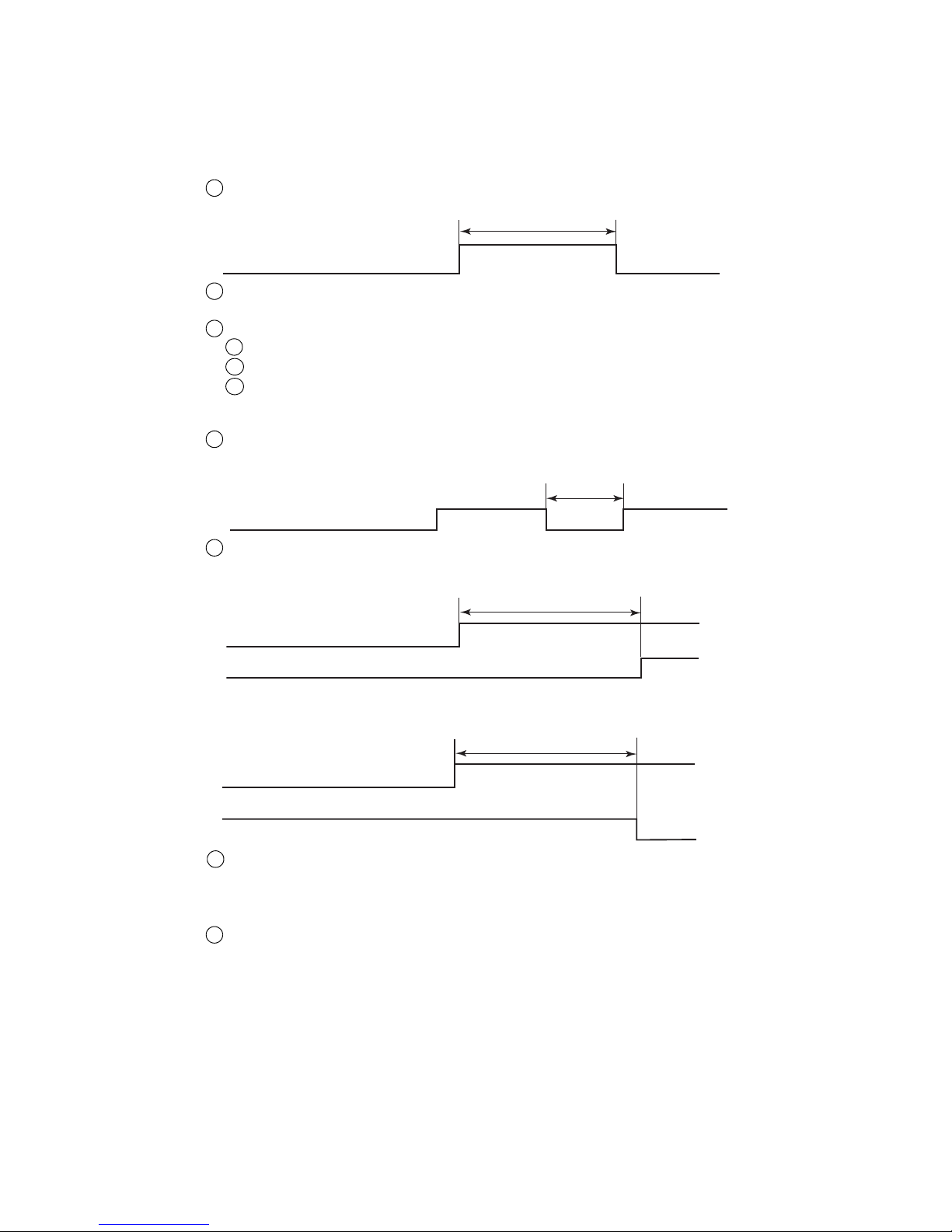
Time until state changes after “Deflection voltage control” is input
t3: Within 3 seconds (Standby→Ready)
2
t2
Deflectionvoltagecontrol
t3
Deflectionvoltagecontrol
Readysignal
t4
Deflectionvoltagecontrol
Readysignal
t1
Remotesignal
4.3.3-3 Remote startup signal input
[Function] This function inputs the same operations as the IJ printer operation state operation keys (“Startup”,
“Shutdown”, “Reset”, “Deflection voltage control”(standby state and Ready to print state
switching)) by external switch or contact signal.
(a) Judgment conditions
(a-1) Remote signals in general
Remote signal ON time t1 shall be 100ms or greater.
Take measures so that multiple remote signals are not turned ON simultaneously.
If multiple signals are turned ON simultaneously, the signals will not be accepted.
Signals cannot be received in the following cases:
When a confirmation window is open
When the Circulation control screen is opened by maintenance function
When the Touch screen coordinate correction screen is opened by auxiliary function
1
2
3
i
ii
iii
(a-2)“Deflection voltage control”
When “Deflection voltage control” is input continuously, a certain OFF period is necessary.
When t2 is 10ms or less, OFF is not detected and the signal is not received.
1
t4: Within 100ms (Ready→Standby)
When “Deflection voltage control” is turned ON, state confirmation is necessary.
If “Deflection voltage control” is turned on by mistake during printing, printing is aborted even in
the process of printing and the IJ printer is switched from the Ready state to the Standby state.
To prevent erroneous printing, input this signal when the printer is in a not printing state.
When the Product speed matching function is used, and when the print description is changed when
the line is stopped during printing, etc., the IJ printer will enter the Standby state by this signal and
the print description can be changed.
3
4
Page 41
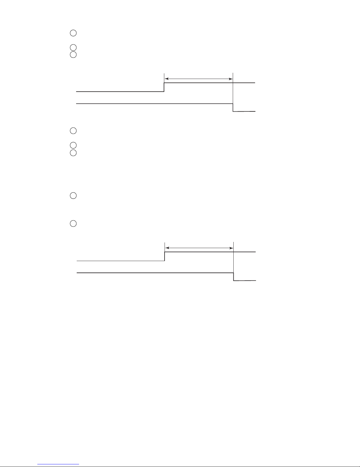
4-20 ●Input/output (I/O) specifications
t5
Resetsignal
Faultsignal
t6
Shutdownsignal
Readysignal
(a-3) “Reset signal”
Input this signal when the fault signal is ON.
In addition, after signal input, check if “Fault” is cleared.
Turn on the “Reset signal” 30 seconds or longer after the IJ printer power is turned on.
The time until the fault is cleared after the “Reset signal” is input
t5: within 100ms
1
2
3
(a-4)“Startup signal”
The “Startup signal” is a signal that specifies an automatic procedure up to ink ejection.
Handle it with care.
When the “Startup signal” is turned ON during ink stop processing, it is ignored.
Turn on the “Startup signal” 30 seconds or longer after the IJ printer power is turned on.
In addition, input this signal after checking if the “Fault” is cleared.
Moreover, it takes about 2 minutes for the IJ printer to enter the Ready to print state after the
“Startup signal” is turned ON.
(a-5) “Shutdown signal”
Turn off the power after confirming that the IJ printer has entered the Stop state after the “Shutdown
signal” is turned ON
It takes about 3 minutes for the IJ printer to enter the Stop state after the “Shutdown signal” is turned
ON.
The time until the state changes after the “Shutdown signal” is input
t6: within 100ms
1
2
3
1
2
(Notes)
(1) For key input, input must be confirmed, but when an external signal is input, processing is
performed in accordance with the signal instructions. Especially, since “Startup”(startup
signal) specifies ejection of the ink, handle it with care.
(2) When a confirmation window is opened, input of all remote operation signals is disabled.
Re-input the signals after the confirmation window is closed.
When the line monitor screen is displayed, input of all the remote operation signals is
disabled.
(3) When the Touch screen coordinate correction or Circulation control screen is displayed,
input of all the remote operation signals is disabled. Re-input the signals after a different
screen was displayed.
(4) The remote operation signals are enabled even when a rotary encoder is used and the
conveyer is stopped during printing.
(5) When the Shutdown signal is input while the Fault window is open, the ink is stopped with
the window remaining displayed.
Page 42
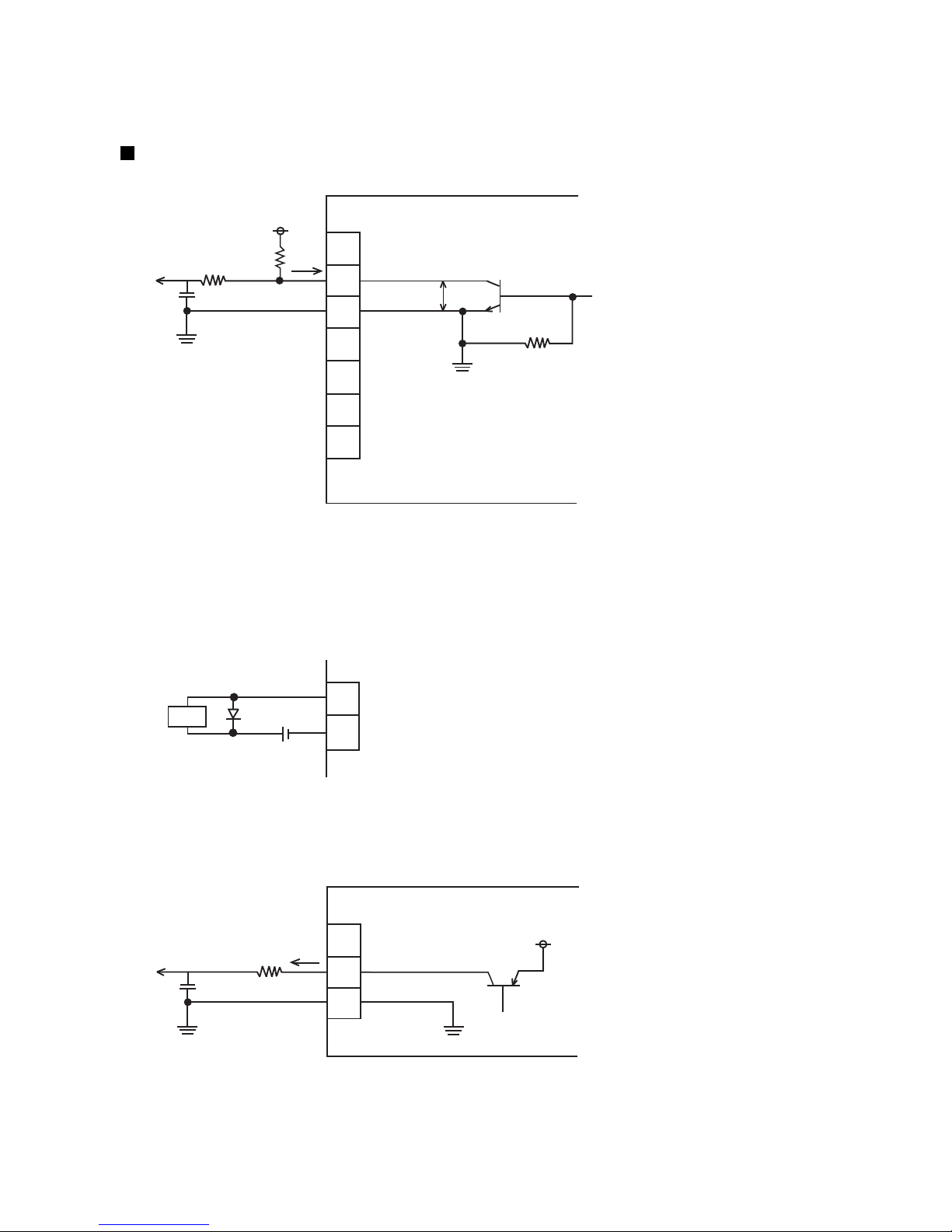
●Input/output (I/O) specifications 4-21
16
17
24
25
27
28
26
Printoutput
Onlineoutput
GND
Ready
GND
Fault
Warning
Vd
*Othersignalsarealsothesame.
IL
VCE
IJprinter
TB1
17
24 GND
Onlineoutput
Load
*Othersignalsarealsothesame.
20
21
24
Printoutput
Onlineoutput
GND
24V
IL
V
CE
R
IJprinter
4.3.4 Output function
The state of the IJ printer is monitored by connecting the print output (“Print-in-progress” or “Print.complete”),
online output, Ready, Fault, and Warning signals to pins 16 to 28 of TB1. (No-contact (transistor) output)
Internal circuit diagram
(a) NPN interface output (no-voltage output)
●The output transistor is open collector, and the logic is transistor ON at operation ON.
●The voltage and current used by the external equipment must satisfy the following specifications:
1L 20mA (V
CE : TYP0.6V, MAX2V)
Vd DC30V
●Wiring precautions
<
=
<
=
●When the load is a relay, solenoid, or other inductive load, connect a diode to prevent generation of a
counter electromotive force in parallel with the load.
●The load circuit is DC dedicated. It cannot be used with an AC load.
(b) PNP interface output (voltage output)
●The output transistor is open collector and the logic is transistor ON (voltage output) at operation ON.
●When used with external equipment, the following shall be satisfied:
1L 10mA(V
CE : TYP0.6V, MAX2V), Guide line of R : R 2.2kΩ
Withstand voltage 50VDC or greater (2 times or more of the voltage used)
<
=
>
=
Page 43
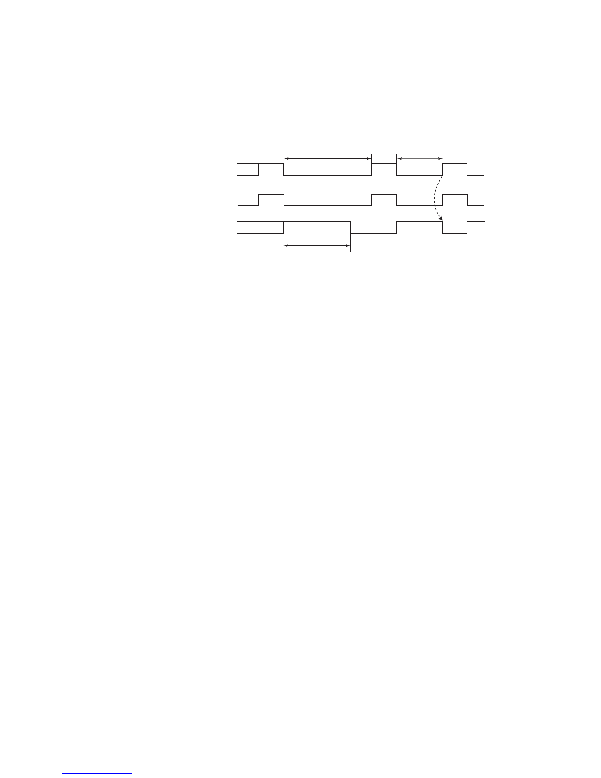
4-22 ●Input/output (I/O) specifications
Printingoperation
Print-in-progresssignal
Print.completesignal
1sec
OFF
ON
Print-in-progress
OFF
ON
Under1sec
*
*Whenthenextprintingoperationstartedwithin1second,turnedOFFat
thestageatwhichtheprintingoperationstarted.
1secorgreater
4.3.4-1 Print output signal (NPN interface output : TB1-16,
PNP interface output : TB1-20)
[Function] This function outputs a signal to the outside at IJ Printer Print.complete or Print-in-progress.
(a) Print-in-progress and Print.complete switching
Switching of the Print-in-progress and Print.complete signals is set at the User environment setup screen.
(See Instruction manual “6.1 Set the user environment”.)
(b) Signal timing
4.3.4-2 Online output signal (NPN interface output : TB1-17,
PNP interface output : TB1-21)
[Function] This function outputs a signal to the outside when the IJ printer is online.
4.3.4-3 Ready output (NPN interface output only : TB1-25)
[Function] This function outputs a signal to the outside to indicate IJ printer Ready-to-print state or input mode
state. (It is used to stop the conveyer when the IJ printer cannot print to prevent the product from
flowing without being printed.)
4.3.4-4 Fault signal output (NPN interface output only : TB1-27)
[Function] This function outputs an “IJ printer in fault mode” signal to the outside.
4.3.4-5 Warning signal output (NPN interface output only : TB1-28)
[Function] This function outputs an “IJ printer in warning mode” signal to the outside.
Page 44
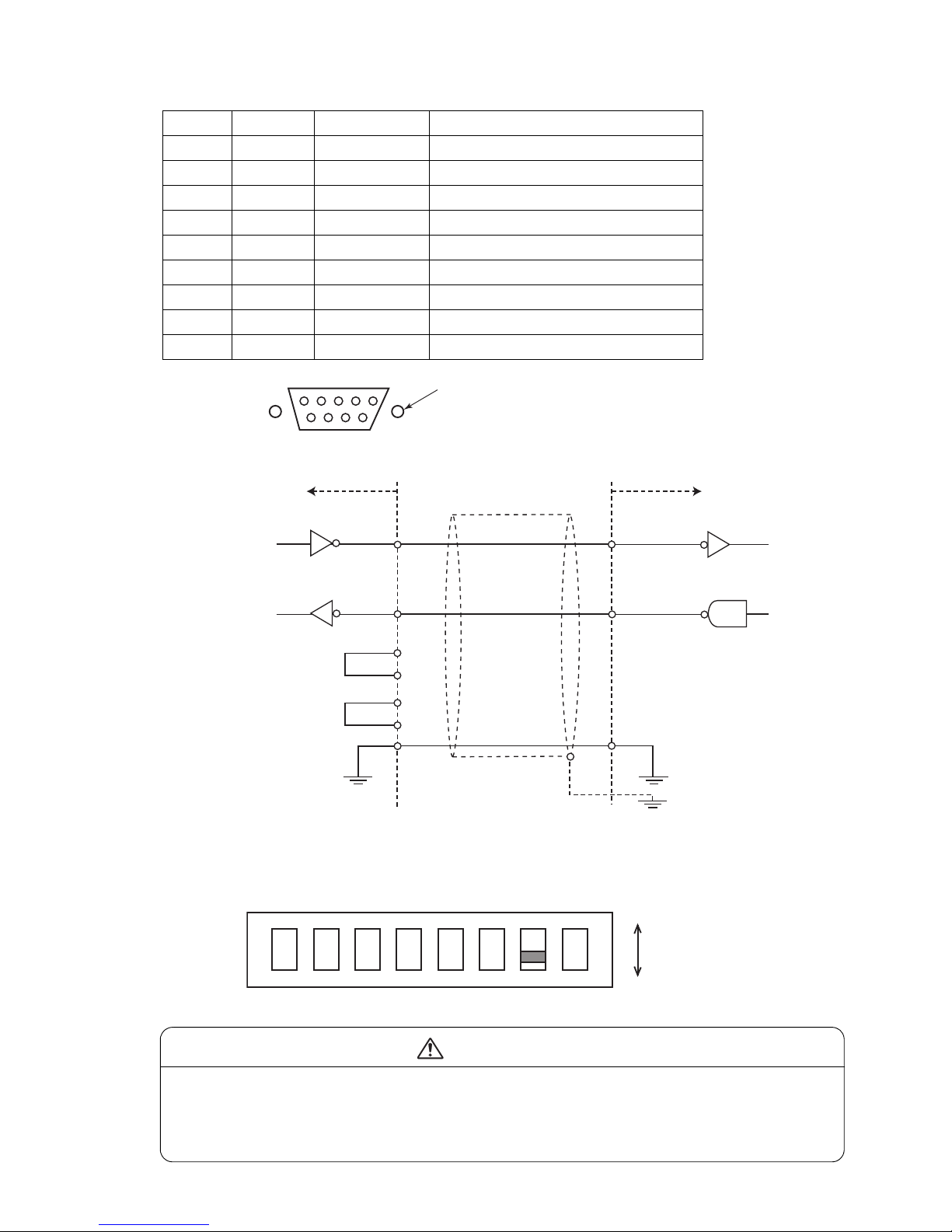
●Input/output (I/O) specifications 4-23
Attachingscrew:inchscrew
ConnectoronEZJ110board:9-pinDsub-connector(plug)
IJprinter
SD
Output
#3
RD Input
#2
Externalunit
RD
SD
Transmission
Reception
SG SG
FG
#5
Cablelength:maximum5m
DTR
DSR
#4
#6
RTS
CTS
#7
#8
ON
1
SW1
ON
OFF
2 3 4 5 6 7 8
4.3.4-6 External communication (RS-232C)
External equipment is connected to the IJ printer by serial communication of RS-232C.
Pin No. Name Input/Output Remarks
1(NC) -
2 RD Input
3 SD Output
4 DTR - Connect with DSR by IJ printer side.
5SG -
6 DSR - Connect with DTR by IJ printer side.
7 RTS - Connect with CTS by IJ printer side.
8 CTS - Connects with RTS by IJ printer side.
9(NC) -
Turn OFF SW1-bit7 on EZJ 110 board.
●Do not bundle it together with heavy-current signals inside and outside the equipment
so that it will not be influenced by noise from a heavy-current signals (a connection
signal to the power supply, etc).
●Use a cable which is as short as possible.
CAUTION
Page 45
4-24 ●Input/output (I/O) specifications
4.3.5 Product speed matching function without a rotary encoder
(RX-S only)
4.3.5-1 Auto product speed matching function
Auto product speed matching function is used for detecting the change of speed of the conveyer carrying
print target using the print target detector connected to the IJ printer, and prints each vertical line of the print
according to the change of speed in the same way as the Speed matching function using a rotary encoder.
Ensure to confirm the print start position and check for the slip of the print target by thoroughly testing before
using this function. If the print start position or the character width of print vary widely as a result of the test,
use the Speed matching function using a rotary encoder.
Cases that the speed can not be matched
No. Conditions of use
1
In case the print target slips on the conveyer between after the print target passes the print target
detector and before IJ printer complete printing.
2
In case the carrying speed changes or the conveyer stops between after the print target passes the
print target detector and before IJ printer complete printing.
4.3.5-2 Print target detector
●Use a no-contact (transistor) output type print target detector with a photoelectric sensor with built-in
amplifier which detects the target using the optical beam.
●To start the print from the edge of the print target, place the print target detector so that the "Distance
between the print head and print target detector" is larger in width than print target.
4.3.5-3 IJ Printer setup
●Configure the setting for "Product speed matching", "Print target width", and "Actual print width" on "Print
Specifications" screen. (See Chapter 4.14 "Set the print specifications" in the Instruction Manual)
●Set "Auto" for "Product speed matching".
●Enter "Print Target width" and "Actual Print width" in mm.
The value for "Actual Print width" must be smaller than "Print Target width".
●"Enable" the "Speed compensation" as required.
When "Speed compensation" is enabled, the print start position is delayed 2 scans
because calculation is performed to reduce the change of the print start position.
The position accuracy of the print start position may be worse than the product speed
matching function using a rotary encoder, because calculation is performed by sensing
the print target detector.
Precaution
●When setting the "Sensor filter" on "Print specifications", set the value as small as possible so that the
Sensor filter function is completed before the target passes the print target detector.
●"Repeat count" on "Print specifications" can not be used at the same time.
●The Character width on the "Print specifications" is automatically set as below depending on the Ink drop
use.
Ink drop use Character width
1/1 002
1/2 001
1/3 to 1/16 000
Page 46

●Input/output (I/O) specifications 4-25
4.3.5-4 Carrying speed
●Set the minimum speed the target print is carried by conveyer to 1m/min.
●If the carrying speed the IJ printer detects is faster than the speed of when the printed without Speed
matching, print is made with the same interval as when the Speed matching function is not used.
(At the time speed exceeds the limit speed in the condition)
●If "Print Target width" or "Actual Print width" on the "Print specifications" is not entered, the print is made
with the same interval as when the Speed matching function is not used.
Page 47

5-1 ●Communication
5. COMMUNICATION
5.1 Overview
The functions described in this document are used to transmit printings and their registration numbers and
enter them into the IJ printer with an external device connected to the IJ printer via an RS-232C serial
communication line.
(1) Printings transmission
● An "item number" and "character string" are transmitted from the external device to the IJ printer.
● The IJ printer receives the "item number" and "character string" and then makes preparations for
making designated prints.
● The printings of print item for which bar codes or increased-width printings can also be transmitted by
the communication functions.
● When a number (alphabetical character) is transmitted via a communications link to a count setting
digit, the default value can be set.
(2) Print data recall transmission
● A print data "message number" is transmitted from the external device to the IJ Printer.
● The IJ printer recalls print data designated by a "message number" and makes preparations for making
prints.
(3) Print data registration transmission
● Transmits Print data's "message number" and "message name" from external unit to the IJ printer.
● The IJ printer provides a "message name" and registers data currently being printed as print data of
"registration No."
(4) Print condition transmission
● The external device transmits "print specifications" and "print format" to the IJ printer.
● The IJ printer receives the "print specifications" and "print format", and prepares for making prints
under the specified conditions.
(5) Calendar conditions transmission, count conditions transmission
● Transmits and sets "initial values", "range" of count conditions, and "offset", "zero suppress" of
calendar condition etc. from external unit to the IJ printer.
(Optional on RX-B)
Page 48

●Communication 5-2
(6) User pattern character transmission
● This function is used to transmit a user pattern and enter it into the IJ printer.
● A transmitted user pattern can be edited using the "Create user pattern" function, which is provided as
an auxiliary function.
(7) On-line/off-line transmission procedure
● Specifies switch of online state and offline state from external unit to the IJ printer.
(8) Remote operation transmission
● Specifies ink ejection/stop, deflection voltage control (on/off) and error reset from external unit to the
IJ printer.
(9) Time control
● Transmits and sets "current time", "calendar time", etc., from external unit to the IJ printer.
● Inquires current time from external unit to the IJ printer and the IJ printer returns "current time".
(10) Communication buffer
● The print contents received through print content transmission will not be reflected in printing
immediately, but will be temporarily held in buffer.
● The print contents are fetched from the buffer one by one for each printing, and reflected in
subsequent printing.
Page 49
5-3 ●Setting Communication Environment
5.2 Setting Communication Environment
5.2.1 Setting Communication Environment
(1) Overview
Function Description Default
State at power-up
● Comm. port is OFF : Offline mode when the
power is turned on.
● Comm. port is ON : Online mode when the
power is turned on.
● OFF fixed : Always offline mode and
you cannot change to the
online mode.
Comm. port is OFF
Communication and
signal error
● Warning : An external communication error and
external signal error are considered to be
"Warning."
● Fault : An external communication error and
external signal error are considered to be
"Fault." The printer does not print even if
the product target detector is turned ON.
Warning
Baud rate
● Sets the baud rate at which communication is
established with the outside.
● Eleven different settings are selectable: 150, 300,
600, 1,200, 2,400, 4,800, 9,600, 19,200, 38,400,
57,600, or 115,200 bps.
4,800bps
Data format
● Sets the data length, parity bit, and stop bits for
communication with the outside.
● The following settings are available.
Data length: 7 or 8 bits
Parity bit: none, odd, or even
Stop bits: 1 bit or 2 bits
Data length: 8 bit
Parity bit : none
Stop bits : 1 bit
Number of comm.
bytes
● Sets the number of character code bytes for
communication with the outside.
● A setting of 1 byte or 2 bytes can be selected.
1 byte
BCC code handling
● Setup can be performed so that no communication
error occurs even if BCC code attached data is
received.
Disable
Communication
mode
● Overwrite-protected: No new data will be received
until the previously received
data is printed.
● Overwrite-enabled : New data is received even if
the previously received data
has not been printed.
The newly received data
overwrites the old data.
Overwrite- protected
Print message
transfer ACK
● t=fixed : The time from receiving the print
description from an external device to
sending ACK becomes nearly fixed
regardless of the transmission volume.
● t=async. : The system will be ready to print
immediately after returning ACK.
t=async.
Print spec. transfer
char. height
● 2 digits: Uses 2-digit data for character height
setting ([00] to [99]) transmission.
● 3 digits: Uses 3-digit data for transmission.
2 digits
2
1
3
Page 50
●Setting Communication Environment 5-4
Comm. env. setup
2015.07.0712:45
Back
Com=0
[Stop ]
State at power-up
Communication and signal error
<Transmission condition by port>
Target port
Baud rate (bps)
<Data format>
Data length
Parity bit
Stop bits
<Standard communication>
Number of comm. bytes
BCC code handling
Communication mode
Print message transfer ACK
Print spec transfer char height
Comm. port in ON
Disable
4800
M
Manual
Startup
HOME
Prev.Dsp.
NextDsp.
Warn.
Fault
1 bits
2 bits
1 byte
2 bytes
Disable
Enable
2 digits
3 digits
8 bits
7 bits
Standard port
overwrite-protected
overwrite-enabled
t=async.
t=fixed
Changetheon-line
oroff-line.
Comm. env. setup
2015.07.0712:45
Back
Com=0
[Stop ]
Buffer function
Buffer repeat count
Empty Buffer Fault
Timing of Fault
Data Number at Fault
Prev.Dsp.
NextDsp.
0
(0〜9)
(1〜9999)
M
Manual
Startup
HOME
Disable
Enable
0001
Settingofcommunicationbuffer
(Referto"5.9Communicationbuffer".)
Disable
Enable
Print Start
Print. Complete
(2) Operating procedure
Press Communication environment setup from the Environment setup menu.
The "Communication environment setup" screen appears.
1
Press Next settings .
The second screen appears.
2
Page 51
5-5 ●Setting Communication Environment
5.2.2 Transmission Specifications
(1) Communication method : Half duplex
(2) Startup method : Started up by host
(3) Synchronization method : Asynchronous
(4) Transmission method : Bit serial transmission
(5) Baud rate : 150, 300, 600, 1,200, 2,400, 4,800, 9,600, 19,200, 38,400,
57,600, 115,200(bps)
(6) Codes transmitted : Alphanumerical characters, symbols, dedicated characters,
user pattern characters, and punctuation characters
(7) Data format : Formats A through J are selectable (see the table below).
No other formats can be chosen.
Data format table
Item Start bit Data length Parity bit Stop bits
Format (bits) (bits) (bits) (bits)
A 1 7 1 (even) 2
B171 (odd)2
C 1 7 1 (even) 1
D171 (odd)1
E18None2
F (default) 1 8 None 1
G 1 8 1 (even) 1
H181 (odd)1
I 1 8 1 (even) 2
J181 (odd)2
Selecting a data length of 7 bits allows you to transmit alphanumerical characters
and symbols but inhibits you from transmitting punctuation characters and using
2-byte codes to send dedicated characters and user pattern characters.
(8) Bit configuration
Formats A and B
Start b0 b1 b2 b3 b4 b5 b6 Parity Stop Stop
Formats C and D
Start b0 b1 b2 b3 b4 b5 b6 Parity Stop
Formats E
Start b0 b1 b2 b3 b4 b5 b6 b7 Stop Stop
Formats F
Start b0 b1 b2 b3 b4 b5 b6 b7 Stop
Formats G and H
Start b0 b1 b2 b3 b4 b5 b6 b7 Parity Stop
Formats I and J
Start b0 b1 b2 b3 b4 b5 b6 b7 Parity Stop Stop
Order of code transmission: Transmission occurs beginning with the least significant bit (b0).
(9) Error control
● Vertical parity error (detection on an individual character basis)
● Overrun error
● Framing error
Page 52
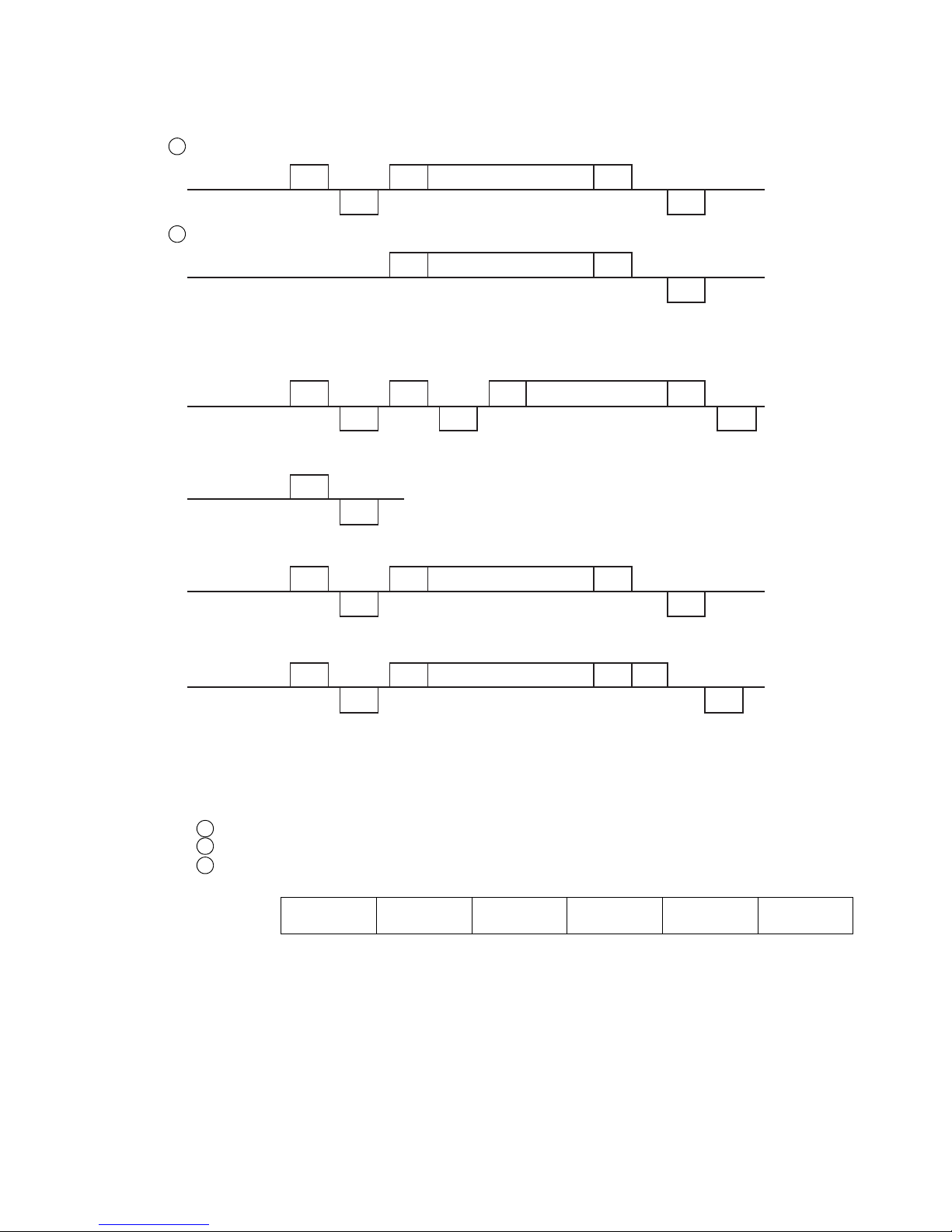
●Transmission Sequences 5-6
5.3 Transmission Sequences
5.3.1 Common Transmission Sequences
(1)Basic transmission operation.
When ENQ and ACK are present:
External device
IJ printer
ENQ
ACK
STX
Text
ETX
ACK
External device
IJ printer ACK ACK
ACK
DC2 ENQ
STX
Text
ETX
External device
IJ printer
STX
Text
ETX
ACK
External device
IJ printer
ENQ
NAK
External device
IJ printer
ENQ
ACK
STX
Text
ETX
NAK
External device
IJ printer
ENQ
ACK
STX
Text
ETX BCC
ACK
(2)When DC2 (retransmission) code is used
(When no response is received though ENQ has been issued and yet the contents of print
area switched)
When ENQ is omitted:
(3)When the IJ printer is incapable of receiving data or is off-line
(4)Abnormal transmission operation (when the text contains an erroneous message)
(5)When BCC code is included
(6)When the IJ printer power is OFF
No response will be returned for any code transmission from the external decice.
(7) The printings, print specifications, print format, and user pattern data can be
consecutively transmitted in the following order in a single session.
Print format
Print specifications
Printings
2
1
3
(Example)
Print format Print format Print format
Print
specification
Print
specification
Print content
The user pattern can be positioned anywhere within the above data chain.
The overall column setup data must be transmitted independently. If an attempt is made to send
it together with the other data, a communication error (NAK response) occurs.
The print data recall must also be transmitted independently. Even if it is sent together with the
other data, no error occurs. However, the print data recall takes precedence, rendering the other
data invalid.
(8) Up to 3000 bytes of data can be transmitted at a time, including "STX" and "ETX".
If the 3000-byte limit is exceeded, a communication error (NAK response) occurs.
2
1
Page 53
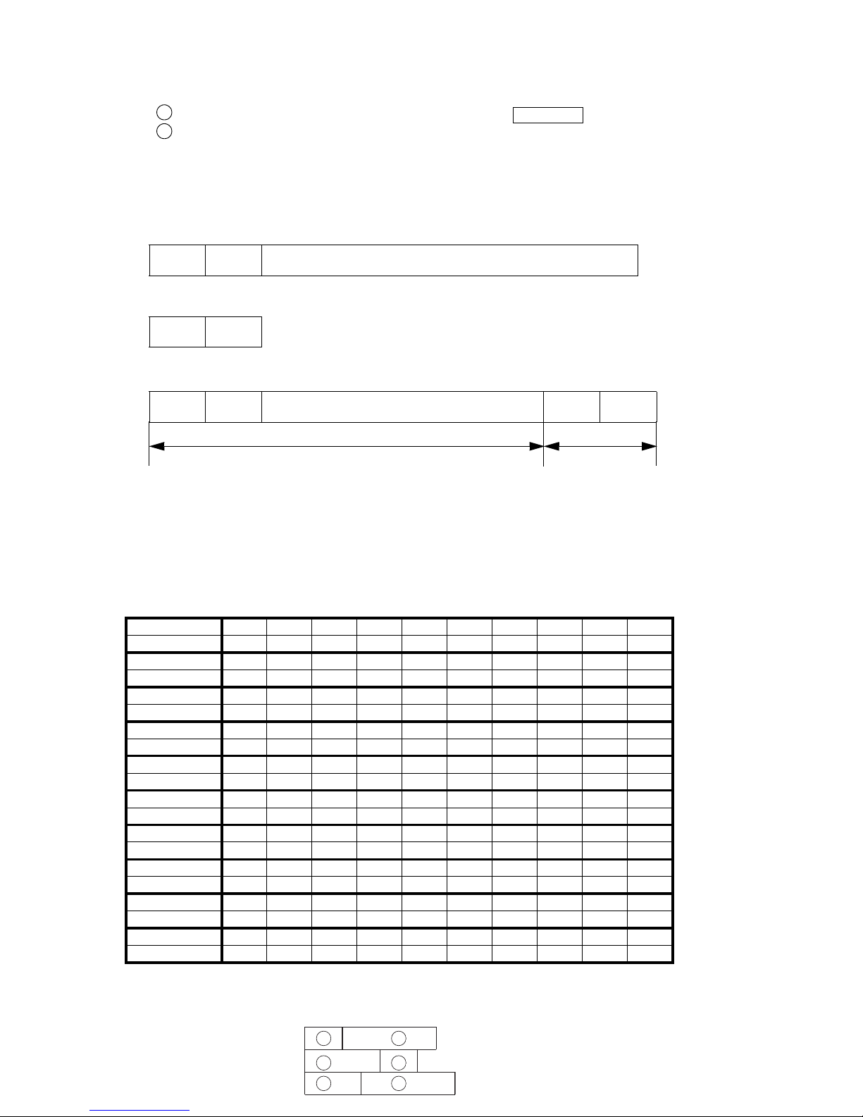
5-7 ●Transmission Sequences
1
2
3
4
5
6
Row1Row2
(9) Any data transmitted by communication (print contents, print specifications, print
format, and user pattern) is not stored except in the following cases.
[Conditions for storing the data]
When the ink is stopped after communication by the Shut down key or a stop signal.
At 01 minute of every hour.
(10) Transmit to the existing print item after creating a transmission objective print item.
2
1
5.3.2 Printings Transmission
5.3.2-1 Text
(1) When printings are to be changed
DLE
Item
number
Printings
(2) If deleting character string within print item
DLE
Item
number
(3) When multiple printings are to be designated
DLE
Item
number
Printings DLE
Item
number
Printings change
Printings erasure
● Multiple print items can be consecutively transmitted within one session.
● Print items are to be designated by specifying the item numbers. The item numbers need not be sorted
● Print items not transmitted are not changed.
● Both calendar characters and count characters can be transmitted.
● If printings are transmitted for a print item for which Micro QR setup is completed, a communication
error occurs.
5.3.2-2 Item number
Item number12345678910
Code 31H 32H 33H 34H 35H 36H 37H 38H 39H 3AH
Item number 11 12 13 14 15 16 17 18 19 20
Code 3BH 3CH 3DH 3EH 3FH 40H 41H 42H 43H 44H
Item number 21 22 23 24 25 26 27 28 29 30
Code 45H 46H 47H 48H 49H 4AH 4BH 4CH 4DH 4EH
Item number 31 32 33 34 35 36 37 38 39 40
Code 4FH 50H 51H 52H 53H 54H 55H 56H 57H 58H
Item number 41 42 43 44 45 46 47 48 49 50
Code 59H 5AH 5BH 5CH 5DH 5EH 5FH 60H 61H 62H
Item number 51 52 53 54 55 56 57 58 59 60
Code 63H 64H 65H 66H 67H 68H 69H 6AH 6BH 6CH
Item number 61 62 63 64 65 66 67 68 69 70
Code 6DH 6EH 6FH 70H 71H 72H 73H 74H 75H 76H
Item number 71 72 73 74 75 76 77 78 79 80
Code 77H 78H 79H 7AH 7BH 7CH 7DH 7EH 7FH 80H
Item number 81 82 83 84 85 86 87 88 89 90
Code 81H 82H 83H 84H 85H 86H 87H 88H 89H 8AH
Item number 91 92 93 94 95 96 97 98 99 100
Code 8BH 8CH 8DH 8EH 8FH 90H 91H 92H 93H 94H
● The order of print items is indicated below.
(3-column example) Circled number: Item number
Page 54
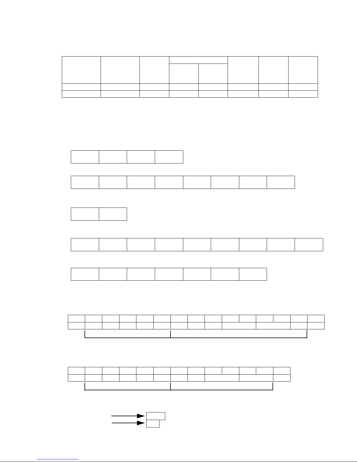
●Transmission Sequences 5-8
5.3.2-3 Printings
● An array of “character codes”.
● The coding system varies with the mode which is designated by the “Number of communication bytes”
setting entered from the communication environment setup screen.
Number of
communication
bytes
Alphanumerical
characters and
symbols
Dedicated
characters
User pattern
Punctuation
mark
Katakana
Calendar
characters,
Count
characters
(00 to 47) (48 to 199)
1-byte mode ASCII ASCII ASCII 2-byte code 2-byte code 2-byte code 2-byte code
2-byte mode ASCII 2-byte code 2-byte code 2-byte code 2-byte code 2-byte code 2-byte code
5.3.2-4 Character codes
(1) 2-byte code (number of communication bytes: 1-byte mode)
● For 1-byte mode, 2-byte codes are sandwiched between "SI" and "SO."
● One character
SI
High-order
byte
Low-order
byte
SO
● Two or more characters
SI
High-order
byte
Low-order
byte
High-order
byte
Low-order
byte
High-order
byte
Low-order
byte
SO
(2) 2-byte code (number of communication bytes: 2-byte mode)
High-order
byte
Low-order
byte
(3) Mixture of ASCII and 2-byte codes (number of communication bytes: 1-byte mode)
ASCII ASCII SI
High-order
byte
Low-order
byte
High-order
byte
Low-order
byte
SO ASCII
(4) Mixture of ASCII and 2-byte codes (number of communication bytes: 2-byte mode)
ASCII ASCII
High-order
byte
Low-order
byte
High-order
byte
Low-order
byte
ASCII
5.3.2-5 Example of print contents transmission
(1) Example when No. of communication bytes: 1 byte mode
02H 10H 31H 41H 42H 43H 10H 32H 0FH F2H 52H F2H 52H 0EH 03H
STX DLE 1 A B C DLE 2 SI Calendar Calendar SO ETX
Print item 2
(2) Example when No. of communication bytes: 2 byte mode
02H 10H 31H 41H 42H 43H 10H 32H F2H 52H F2H 52H 03H
STX DLE 1 A B C DLE 2 Calendar Calendar ETX
Print item 1 Print item 2
[Transmission results]
Print item 1
Print item 2
ABC
DD
DD:Calendar character "day"
Print item 1
Page 55
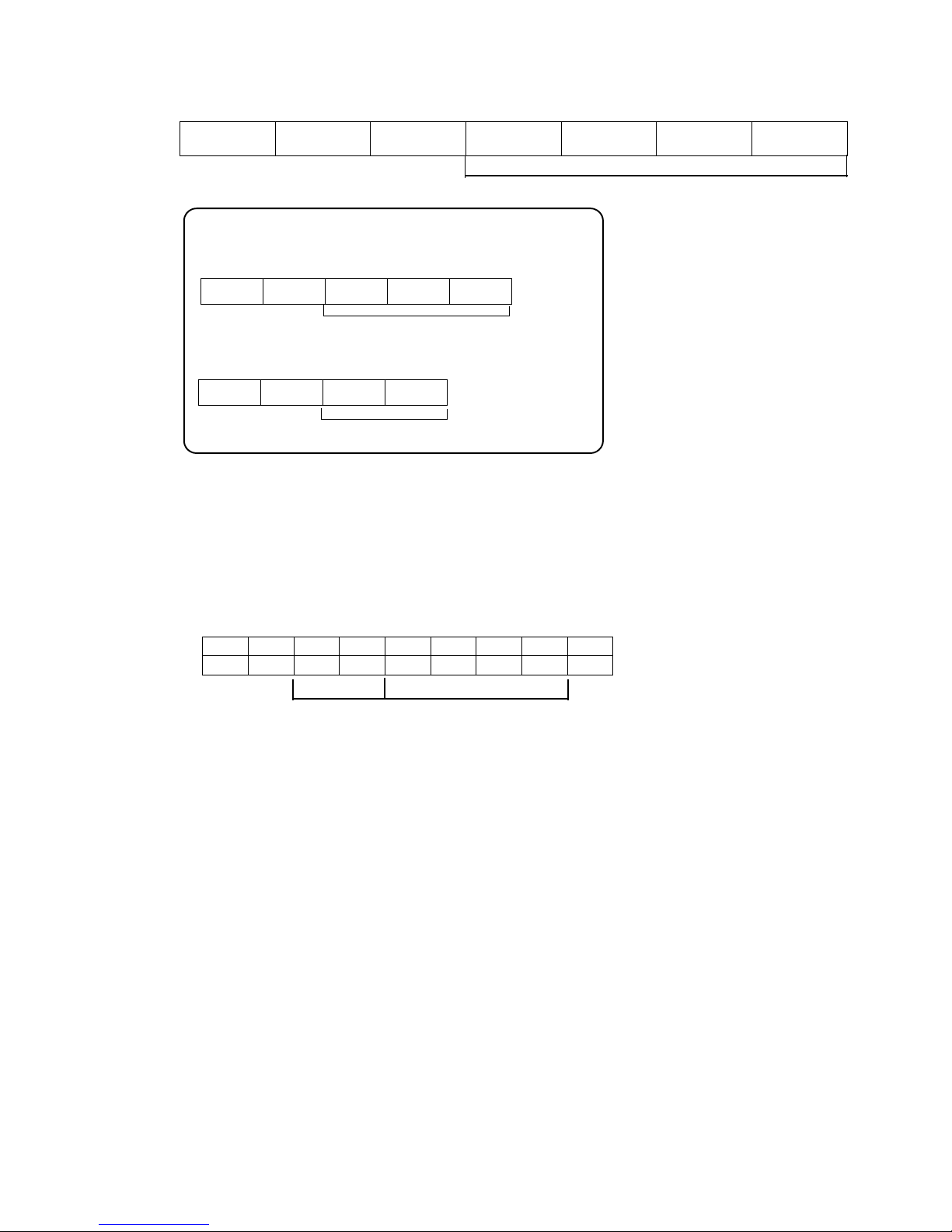
5-9 ●Transmission Sequences
5.3.3 Print Data Recall Transmission
5.3.3-1 Text
ESC2 Header 20H
Classification
31H
1000s place 100s place 10s palce Units place
Print data message number (0001 to 2000)
5.3.3-2 Print data message number
● An already saved print data number is to be designated as the print data message number.
● The message number is expressed by a combination of three ASCII codes.
5.3.3-3 Example of print contents transmission
(1) Example of specifying 4-digit print data registration No.
02H 1FH 20H 31H 30H 30H 31H 32H 03H
STXESC2 10012ETX
[Transmission results]
Calls print data of print data message number 12.
ESC Header 56H 100s place 10s place Units place
Print data message number (001 to 999)
ESC Header 26H 10s place Units place
Print data message number (01 to 99)
[Existing machine message] Existing machine message can also be used.
Header, classification
Print data message number
Page 56
●Transmission Sequences 5-10
ESC Header 25H 10s place Units place ESC Header 86H Message name (1 to 12 diguts)
Print data message number (01 to 99)
5.3.4 Print data registration transmission
5.3.4-1 Text
● Specifies message number
ESC2 Header 21H
Classification
31H
1000s place 100s place 10s place Units place
● Specifies registration No. and message name.
ESC2 Header 21H
Classification
31H
1000s place 100s place 10s place Units place
Print data message number (0001 to 2000)
ESC2 Header 21H
Classification
32H
Message name (1 to 12 digits)
Message name : ASCII code (20H to 5FH, 61H to 7AH)
.
ESC Header 55H 100s place 10s place Units place
Print data message number (001 to 999)
ESC Header 25H 10s place Units place
Print message number (01 to 99)
.
ESC Header 55H 100s place 10s place Units place ESC Header 86H Message name (1 to 12 diguts)
Print data message number (001 to 999)
Print data message number (0001 to 2000)
(Contd.)
[Existing machine message] Existing machine message can also be used.
● Specifies registration No.
● Specifies registration No. and message name.
Page 57
5-11 ●Transmission Sequences
5.3.4-2 Message name
(1) message number specified
● A message name is automatically attached when print data is registered.
● Based on the message name displayed in the upper left hand corner of the screen, the last 4 digits are
replaced with the message number and used as the new message name.
(Example) Registering for No. 123
Contents displayed in upper left hand corner of the screen :“ABCDEFGHIJKL”
Message name after registration :“ABCDEFG 0123”
(2) Message number and message name specified
● The specified message name attached when print data is registered.
(3) Same message name is used for other message number
● If a message name is in use for other message number, new message name will be created by using
original message name as a base and replacing its 7th and 8th digits with AA~ZZ.
(Example) Message name [ABC] is already registered on No.1. Register on No.2 using identical
message name.
Message name of No.1: [ABC ]
Message name of No.2: [ABC AA ]
(4)Characters available for message name
● Characters used for setting the message name transmission are different from characters used in
manual input on registration screen.
Function
Alphameric character/
Symbols
Accent character/
Arabic character
Manual input Available Available
Message name transmission Available Unavailable
5.3.4-3 Supplement
● When transmitting print data together with the print contents, send the print contents last.
5.3.4-4 Example of print data registration transmission
(1) Example of registering by specifying message name
02H 1FH 21H 31H 30H 30H 31H 32H 1FH 21H 32H 41H 42H 43H 03H
STXESC2!10012ESC2! 2ABCETX
Header, classification
Header, classification
Message name
[Transmission results]
Massage name "ABC" is assigned to current print data and is registered under message number 12.
Numbers/symbols (ASCII code): 20H to 5FH, 61H to 7AH
Print data message unmber
Page 58
●Transmission Sequences 5-12
5.3.5 Print Condition Transmission
5.3.5-1 Text
(1)Line count / print format uniformity
ESC2 Header 22H Classification 31H
● Line count and print format are made uniform for all print items.
● Line count of all rows are made uniform based on the first row.
● Space between stages, character size, space between characters, whether or not to use bar code and
double width size are made uniform based on the setting value of the first print item.
● Send the message independently. The message cannot be sent together with print format, print
specs., and print contents.
ESC Header 2BH 30H
(2)Configuration of print format text
● Print item not specified
ESC2 Header 70H Item No. Print format text
ESC2 Header 24H Item No. Print format text
Item No. specified (1 to 100)
[Existing machine message] Existing machine message can also be used.
Print format text
If item No. is not specified, it is set for all items.
To transmit print format and print specs. consecutively, transmit in the order of print format
and print specs. If transmitted the other way round, an error will occur.
2
1
● Print item specified
Item No. specified (1 to 100)
Only specified print item is applicable for change.
[Existing machine message] Existing machine message can also be used.
Page 59
5-13 ●Transmission Sequences
(3)Print format text
● Line count and Line spacing
ESC2 Header 22H
Classification
32H
Line count Line spacing
Line count (1 to 5)
Line spacing (0 to 2)
● Character size and inter-character space
ESC2 Header 23H
Classification
31H
Character size 10s place Units place
● Increased width
ESC2 Header 23H
Classification
32H
Increased
width
Increased width (1 to 9)
● Bar code type (Type change, Bar code "not used" → "used")
ESC2 Header 23H
Classification
33H
Type
Bar code type (30H to 46H)
● Bar code "used"→ "not used"
ESC2 Header 23H
Classification
33H
30H
30H :Bar code "not used"
● Readable code (Bar code EAN-13)
ESC2 Header 23H
Classification
34H
Code
● Prefix code (Bar code EAN-13)
ESC2 Header 23H
Classification
35H
Tens position Units position
Prefix code (00 to 99)
● Two or more print format items can be consecutively transmitted in a single chain.
Inter-character space (0 to 28)
Character size
(30H to 3CH)
Bar code type
30H : not used
31H : code 39
32H : ITF
33H : NW-7
34H : EAN-13
35H : DM8x32
36H : DM16x16
37H : DM16x36
38H : DM16x48
39H : DM18x18
3AH: DM20x20
3BH: DM22x22
3CH: DM24x24
3DH: Code 128 (Code set B)
3EH: Code 128 (Code set C)
3FH: UPC-A
40H: UPC-E
41H: EAN-8
42H: QR21x21
43H: QR25x25
44H: QR29x29
45H: GS1 DataBar (Limited)
46H: GS1 DataBar
(Omnidirectional)
Readable code type (0: None, 1: 5 x 5, 2: 5 x 7)
Character size
30H : 4x5
31H : 5x5
32H : 5x8(5x7)
33H : 9x8(9x7)
34H : 7x10
35H : 10x12
36H : 12x16
37H : 18x24
38H : 24x32
39H : 11x11
3AH: 5x3(Chimney)
3BH: 5x5(Chimney)
3CH: 7x5(Chimney)
Page 60
●Transmission Sequences 5-14
ESC Header 22H Line count Line spacing
Line count (1 to 5)
● Line count and Line spacing
Line spacing (0 to 2)
ESC Header 21H Character size
inter-character
space
Character size (1 to 5)
● Character size and inter-character space
inter-character space (0 to 8)
ESC Header 2AH Type
● Bar code type
Bar code type (30H to 3CH )
ESC Header 29H 30H
● Bar code "used"→ "not used"
Used or not used
(0:not used, 1:used)
ESC Header 7DH Code
● ID code (Bar code EAN-13)
Code type
(0:none, 1:5x5, 2:5x7)
ESC Header 2CH 10s place Units place
● Prefix code (Bar code EAN-13)
Prefix code (00 to 99)
ESC Header 3FH Code set
● Code set (Code128)
(0:Code set B, 1:Code set C)
ESC Header 28H Increased width
● Increased width
Increased width (1 to 9)
(4)Print specifications
● Character height
ESC2 Header 25H
Classification
31H
10s place Units place
Character height (00 to 99)
● Ink drop use percentage
ESC2 Header 25H
Classification
32H
10s place Units place
Ink drop use percentage (01 to 16)
● High-speed printing
ESC2 Header 25H
Classification
33H
Mode
Mode (0:HM, 1:NM, 2:QM)
Character size
0 : 5x5
1 : 5x8(5x7)
2 : 7x10
3 : 12x16
4 : 18x24
5 : 24x32
[Existing machine message] Existing machine message can also be used.
ESC Header 29H 31H ESC Header 2AH Type
● Bar code "not used"→ "used"
Used or not used
(0:not used, 1:used)
Bar code type
30H : code 39
31H : ITF
32H : NW-7
33H : EAN-13
34H : DM16x16
35H : DM8x32
36H : Code 128
37H : DM16x36
38H : DM16x48
39H : DM18x18
3AH: DM20x20
3BH: DM22x22
3CH: DM24x24
Page 61
5-15 ●Transmission Sequences
● Character width
ESC2 Header 25H
Classification
34H
1000s place 100s place 10s place Units place
Character width (0000 to 3999)
● Character orientation
ESC2 Header 25H
Classification
35H
Character
orientation
Character orientation (0 to 3)
● Print start delay
ESC2 Header 25H
Classification
36H
1000s place 100s place 10s place Units place
Print start delay (0000 to 3999)
● Print start delay (reverse)
ESC2 Header 25H
Classification
37H
1000s place 100s place 10s place Units place
Print start delay (reverse) (0000 to 3999)
● Product speed matching
ESC2 Header 25H
Classification
38H
Character
orientation
Product speed matching (0:Time-based, 1:Encoder based)
● Pulse rate division Factor
ESC2 Header 25H
Classification
39H
100s place 10s place Units place
Pulse rate division Factor (001 to 999)
● Repeat count
ESC2 Header 25H
Classification
3DH
1000s place 100s place 10s place Units place
Repeat count (0000 to 9999)
● Repeat intervals
ESC2 Header 25H
Classification
3EH
10000s place 1000s place 100s place 10s place Units place
Repeat intervals (00000 to 99999)
● Target sensor timer
ESC2 Header 25H
Classification
3FH
100s place 10s place Units place
Target sensor timer (000 to 999)
Page 62
●Transmission Sequences 5-16
● Target sensor filter
ESC2 Header 25H
Classification
40H
Division
Division (1:time setup, 2:until end of print)
● Target sensor filter setting value
ESC2 Header 25H
Classification
41H
1000s place 100s place 10s place Units place
Value (0000 to 9999)
● Two or more print specification items can be consecutively transmitted in a single chain.
ESC Header 30H 10s place Units place
●Character height
ESC Header 31H 100s place 10s place Units place
Character width (000 to 199)
● Character width
ESC Header 35H 1000s place 100s place 10s place Units place
●Repeat count
Repeat count (0000 to 9999)
ESC Header 34H 1000s place 100s place 10s place Units place
●Repeat intervals
Repeat intervals
(0000 to 9999)
ESC Header 33H 1000s place 100s place 10s place Units place
● Print start delay
Print start delay (0000 to 9999)
Character height (00 to 99)
ESC Header 36H 1000s place 100s place 10s place Units place
● Print start delay (reverse)
Print start delay (reverse) (0000 to 9999)
ESC Header 37H 100s place 10s place Units place
●Target sensor timer
Target sensor timer (000 to 999)
ESC Header 38H 1000s place 100s place 10s place Units place
●Target sensor filter
Target sensor filter (0000 to 9999)
ESC Header 39H Division
Division (1:time setup, 2:until end of print)
●High-speed printing
ESC Header 3AH Mode
Mode (0:HM, 1:NM, 2:QM)
ESC Header 3CH 100s place 10s place Units place
●Pulse rate division Factor
Pulse rate division Factor (001 to 999)
ESC Header 3DH 10s place Units place
●Ink drop use percentage
Ink drop use percentage
(01 to16)
[Existing machine message] Existing machine message can also be used.
ESC Header 32H Units place
Character orientation (0 to 3)
● Character orientation
●Product speed matching
ESC Header 3BH
Character
orientation
Product speed matching (0:Time-based, 1:Encoder based)
Page 63
5-17 ●Transmission Sequences
5.3.5-2 Text setup rules
(1) Line count
● When you change the line count for a print item in a certain column, you must also set the line
count for the other print items that belong to the same column.
(Example)
1357
2468
135
24678
Setting items 7 and 8 to one line
Transmit the line count consecutively to items 7 and 8. If you transmit the line count to only one
of them, a communication error occurs.
● When you change the line count for a print item, you must also set the line count for the other print
items that belong to the same column as the former one.
(Example)
135
24678
Setting items 7 and 8 to two lines
1357
2468
Transmit the line count consecutively to items 7 and 8. If you transmit the line count to only one
of them, a communication error occurs.
(2) Line spacing
● When you transmit one-line setup data for a certain print item, you have to transmit a line spacing
setting of "0" as well as for the same chain as the one-line setup data.
If you do not transmit an line spacing setting of "0", a communication error occurs.
● Ensure that the same line spacing setting is selected for print items belonging to the same column.
In other words, when you transmit a new line spacing setting for a print item in a certain column,
you must consecutively transmit the same setting to the other print items in the same column.
(3) Character size and inter-character space
● The available inter-character space varies with the character size.
See "4.7.4 Set dot matrix, inter-character space, and other parameters" of the Instructions
Manual.
● The total number of vertical dots cannot exceed the limit.
Machine type Maximum number of vertical dots
RX-BD, RX-SD(3-line) 30 dots
Option:RX-SD(4-line) 32 dots
Option:RX-SD(5-line) 32 dots
● Some characters cannot be entered depending on the character size. If a print
item contains an unavailable character after a character size change, its contents
are changed to a space.
See "4.7.4 Set dot matrix, inter-character space, and other parameters" of the Instructions
Manual.
● If an inter-character space other than "0" is transmitted for a print item for which bar code setup is
completed, a communication error occurs.
4
3
Page 64
●Transmission Sequences 5-18
(4) Bar code use and bar code type
● Two or more bar code types cannot coexist.
● When bar code set up is completed for a print item, its inter-character space can not be changed.
(The inter-character space need not be transmitted in this case.)
● When the bar code type is ITF or code128(code set C), you have to observe the following input rules.
If you violate the rules, the contents of an illegal print item will be deleted.
ITF or code128(code set C) input rules
No. Input rule Input example
1
Characters must be paired to make an
entry.
(Correct) [012345]
(Incorrect) [01234]
● Some characters cannot be entered depending on the bar code type.
If any unacceptable character is included in a print item for which bar code setup is completed, the
contents of the print item are changed to a null character. See "4.7.5 Print a bar code" of the
Instructions Manual.
● FNC1 is a control code used for Code128, 2-byte code of 81A6, indicated as on print layout screen.
5.3.5-3 Example of print conditions transmission
(1) Example where print item is not specified
02H 1FH 22H 32H 31H 30H 1FH 25H 36H 30H 31H 32H 33H 03H
STXESC2“210ESC2%60123ETX
02H 1FH 70H 31H 1FH 23H 31H 34H 30H 30H 1FH 70H 33H 1FH 23H 31H 34H 30H 30H 03H
STX
ESC2
p1
ESC2
#1400
ESC2
p3
ESC2
#1400EXT
(2) Example where print item is specified
Header, item No.
Header,
2
1
3
4
2
1
3
4
Line count 1
line spacing 0
Character size 7x10,
inter-character space 0
inter-character space 0
Character size 7x10,
item No.
Header,
classification
Header,
classification
Write position 123
[Transmission results]
All print items are set as 1 stage, write position is changed to 0123.
Header,
classification
Header,
classification
[Transmission results]
Upper stage character size is changed.
※
Page 65
5-19 ●Transmission Sequences
5.3.6 Calendar Conditions Transmission
5.3.6-1 Text
(1) Calendar Conditions Transmission
● Offset
ESC2 Header 28H
Classification
32H
Calendar
block No.
Type 1000s place 100s place 10s place
Units
place
Offset
Offset setting range
Setting item Offset setting range
Year 0000 to 9999
Month 0000 to 9999
Day 0000 to 1999
Hour -023 to 0099
Minute -059 to 0099
● Zero-suppression
ESC2 Header 28H
Classification
34H
Calendar
block No.
Type Mode
ESC2 Header 76H Item No. Type 1000s place 100s place 10s place Units place
Offset
● Offset
● Zero-suppression
ESC2 Header 77H Item No. Type
Disable or
Enable
Disable or Enable (0: Disable;
Calendar block No.
(1 to 8)
Typ e
30H : Year
31H : Month
32H : Day
33H : Hour
34H : minute
Calendar block No.
(1 to 8)
Type
30H : Year
31H : Month
32H : Day
33H : Hour
34H : minute
35H : Weeks
36H : Day of week
Mode
30H : Disable
31H : Zero-suppression (space)
32H : Zero-suppression (character fill)
1: Zero-suppression (space))
Type
30H : Year
31H : Month
32H : Day
33H : Hour
34H : minute
“-” (2DH) when setting negative offset to
hour, minute.
[Existing machine message] Existing machine message can also be used.
Page 66
●Transmission Sequences 5-20
(2) Count Conditions Transmission
ESC2 Header 2CH Classification
Count
block No.
Setting
value
Classification
Item name Setting value
31H Initial value Character code
32H Range 1 Character code
33H Range 2 Character code
34H Update setting range (In progress) 000000 to 999998
35H Update setting range (Unit) 000001 to 999999
36H Increment setting range 01 to 99
37H Direction 0: up, 1: down
38H Jump from Character code
39H Jump to Character code
3AH Reset Character code
3BH Reset signal (option) 0:signal 1, 1:signal 2
3EH External signal count (option) 0: Disable, 1: Enable
Character code of setting value
Mode Alphanumeric User pattern
1-byte mode ASCII ASCII
2-byte mode ASCII 2-byte code
Calendar block No.
(1 to 8)
*) When count characters has been divided (e.g., [ CC CC ]), transmit four-digits characters.
Page 67
5-21 ●Transmission Sequences
ESC Header 80H Item No. Type Setting value
(1) Initial value, Range, Jump from, Jump to, Reset
Code of type
Initial value Range 1 Range 2 Jump from Jump to Reset
ASCII303132333435
ASCII is hexadecimal number.
Character code of setting value
Mode Alphanumeric User pattern
1-byte mode ASCII ASCII
2-byte mode ASCII 1-byte code
*) When count characters has been divided (e.g., [ CC CC ]), transmit four-digits characters.
ESC Header 81H Item No. Type
100000s
place
10000s place 1000s place 100s place 10s place Units place
(2) Update setting range
Code of type
In progress Unit
ASCII 30 31
ASCII is hexadecimal number.
Update setting range
Set item Update setting range
In progress 000000 to 999998
Unit 000001 to 999999
ESC Header 82H Item No. Type 0/1
(3) Direction, External signal count, Reset signal
Direction (0: up, 1: down)
External signal count (0: Disable, 1: Enable)
Reset signa (0:Signal1, 1:Signal2)
Code of type
Direction External signal count Reset signal
ASCII303132
ASCII is hexadecimal number.
ESC Header 83H Item No. Type 10s place Unit place
(4) Increment
Increment setting range
Set item Increment setting range
Increment 01 to 99
5.3.6-2 Example of calendar conditions transmission
(1) Example of offset
02H 1FH 28H 32H 32H 32H 30H 30H 31H 32H 03H
STXESC2(22Day0012ETX
Calendar
Offset 12 days
block No.
[Existing machine message] Existing machine message can also be used.
Header,
classification
[Transmission results]
Defines offset 12 days for calendar block 2.
Page 68
●Transmission Sequences 5-22
5.3.6-3 Example of count conditions transmission
(1) Example of reset
02H 1FH 2CH 3AH 31H 30H 30H 30H 30H 30H 03H
STXESC2, : 100000ETX
Count Reset value 00000
block No.
5.3.7 User Pattern Character Transmission
5.3.7-1 Text
● When the number of communication bytes is set to "1" for communication
ESC2 Header 32H Classification
Character
code
Pattern data array
Character size
● When the number of communication bytes is set to "2" for communication environment setup purposes
ESC2 Header 32H Classification
High-order
byte
Low-order
byte
Pattern data array
Character size Character code
ESC2 Header 20H
Character
size
Character
code
Pattern data array
● When the number of communication bytes is set to "1" for communication environment setup purposes
● When the number of communication bytes is set to "2" for communication environment setup purposes.
ESC2 Header 20H
Character
size
High-order
byte
Low-order
byte
Pattern data array
Character code
Character size
0 : 5x5
1 : 5x8(5x7)
2 : 7x10
3 : 12x16
4 : 18x24
5 : 24x32
Header,
classification
[Transmission results]
Defines reset value 00000 for count block 1.
[Existing machine message] Existing machine message can also be used.
Page 69
5-23 ●Transmission Sequences
5.3.7-2 Character size
● The character size is represented by the codes shown in the following table.
5.3.7-3 Pattern data
(1) Pattern data length
● The pattern data length per character varies with the character size as indicated below.
Character size code table
No. Character size Character size code Pattern data length (bytes) Remarks
14x5 30H 8
25x5 31H 8
3 5x8(5x7) 32H 8
4 9x8(9x7) 33H 16
5 7x10 34H 16
6 10x12 35H 32
7 12x16 36H 32
8 18x24 37H 72
9 24x32 38H 128
10 11x11 39H 32
11 5x3(chimney) 3AH 5
12 5x5(chimney) 3BH 5
13 7x5(chimney) 3CH 7
(2) Pattern data structure
The pattern data structure and data creation rules are explained below.
a) Rules
● Each pattern data unit consists of 8 bits. For each bit, dot presence is indicated by the value 1 (dot
present) or 0 (dot not present).
● Vertically arrayed 8 dots correspond to 8 bits (1 byte).
● For character sizes of 4x5, 5x5, 7x10, 5x7, and 9x7, etc., some portions of 8-bit data are unavailable.
Set such portions to "0". (Even if you set them to "1", processing will be performed with their settings
changed to "0".)
Inter-character space data area
4x5
Inter-character space data area
5x5
Inter-character space data area
5x7
Page 70
●Transmission Sequences 5-24
Inter-character space data area
7x10
Inter-character space data area
9x7
: Unavailable area
Note:The inter-character space is 1 dot at the maximum.
Inter-character space data area
10x12
Page 71
5-25 ●Transmission Sequences
Inter-character space data area
11x11
5x3 (Chimney) 5x5 (Chimney) 7x5 (Chimney)
Page 72
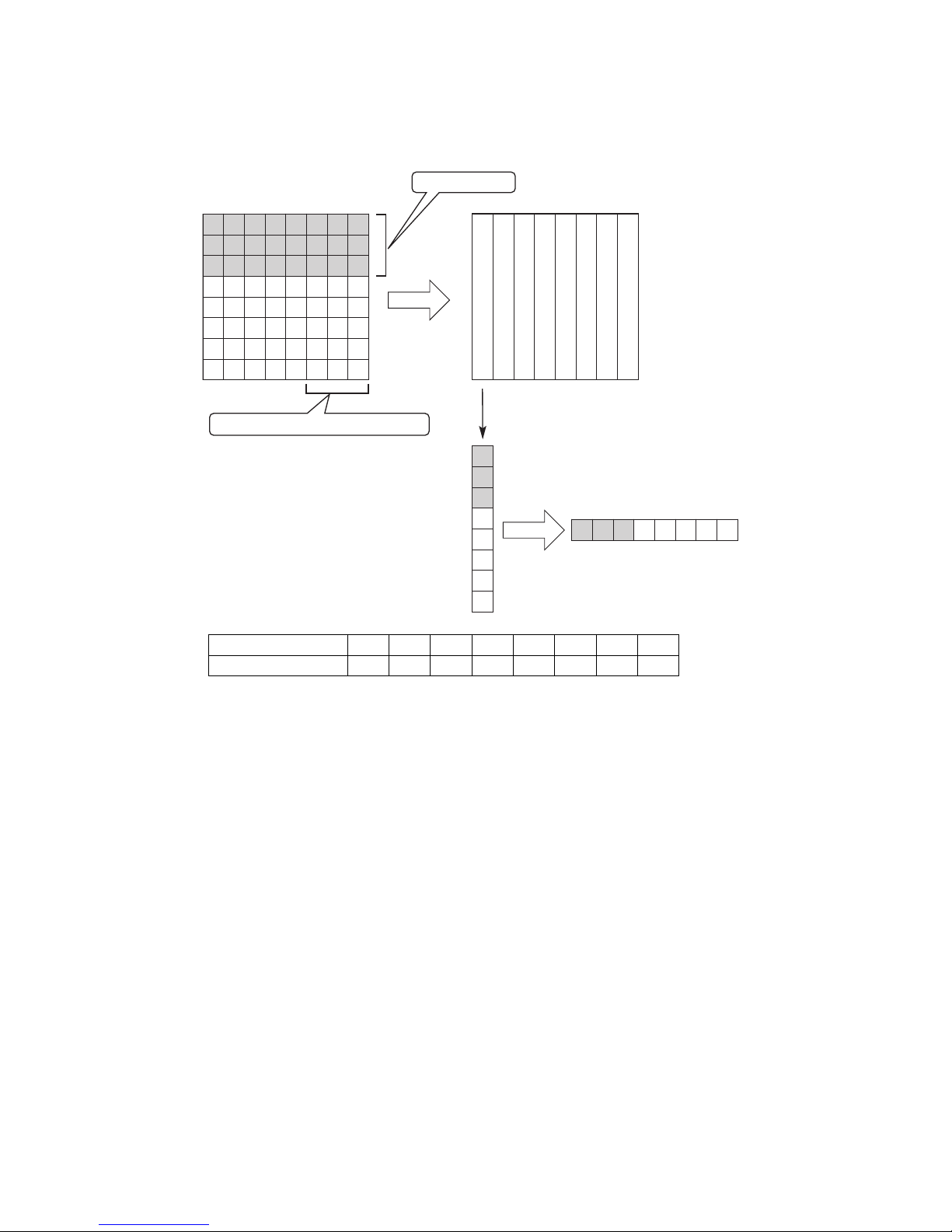
●Transmission Sequences 5-26
Rotated90degreescounterclockwise
Inter-characterspacedataarea
●
● ●
●
●
●
● ● ● ●
●
●
●
● ●
●
●
●
Unusablearea
Removalofthefirstbyte
00 000111=07H
2
7
2
0
Firstbyte
Secondbyte
Thirdbyte
byte
4
byte5byte6byte7byte
8
● For pattern data composition purposes, the data is arranged in successive order, beginning from the
bottom left, from bottom to top and from left to right.
b) Pattern data example
[For a character size of 5x5]
Composition order12345678
Pattern data 07H 0AH 12H 0AH 07H 00H 00H 00H
Page 73

5-27 ●Transmission Sequences
●
●
●
● ●
●
●●●
●
●
●
●
●
●
●
●
●
● ● ● ●
●
●
● ● ●
● ●
●
●
●
● ●
● ●
●
●
●
●
●●● ●
● ● ● ●
● ●●●
● ● ● ● ● ● ●
●
●●● ● ● ●
● ● ● ● ● ●
● ● ● ● ● ●
● ● ●
●
● ●
● ● ● ● ● ● ● ● ● ● ● ● ● ● ● ● ● ●
● ●●● ● ●●● ● ● ● ● ●
●
●
● ● ●
● ●●● ● ●●● ● ● ● ● ● ● ● ● ● ●
● ● ● ● ● ●
● ● ● ● ● ●
● ● ● ● ● ●
● ● ● ● ● ●
● ●
●
● ● ●
●
● ●
●
● ●
● ●
●
● ● ●
●
● ● ● ● ●
3
byte6byte9byte
12
byte15byte18byte21byte24byte
2
byte5byte8byte11byte14byte17byte20byte23byte
1
byte4byte7byte10byte13byte16byte19byte22byte
27
byte30byte33byte36byte39byte42byte45byte48byte51byte54byte57byte60byte63byte66byte69byte72byte
26
byte29byte32byte35byte38byte41byte44byte47byte50byte53byte56byte59byte62byte65byte68byte71byte
25
byte28byte31byte34byte37byte40byte43byte46byte49byte52byte55byte58byte61byte64byte67byte70byte
[For a character size of 18x24]
Page 74
●Transmission Sequences 5-28
5.3.7-4 Character codes
For character code designation, either ASCII codes or 2-byte codes are used.
(1) ASCII codes (when the number of communication bytes is 1)
User pattern character 00 01 02 03 04 05 06 07 08 09 10 11 12 13 14 15
ASCII D0 D1 D2 D3 D4 D5 D6 D7 D8 D9 DA DB DC DD DE DF
User pattern character 16 17 18 19 20 21 22 23 24 25 26 27 28 29 30 31
ASCII E0 E1 E2 E3 E4 E5 E6 E7 E8 E9 EA EB EC ED EE EF
User pattern character 32 33 34 35 36 37 38 39 40 41 42 43 44 45 46 47
ASCII F0 F1 F2 F3 F4 F5 F6 F7 F8 F9 FA FB FC FD FE FF
ASCII codes are in hexadecimal notation.
Applicable to cases where the number of user pattern characters does not exceed 48 (user pattern characters
00 through 47).
(2) 2-byte codes (when the number of communication bytes is 2)
User pattern character 00: F140 = high-order byte F1 + low-order byte 40
See “5.4.1 Code Tables”.
5.3.7-5 Supplement
(1) If the same character code is used to transmit two or more user pattern character data in a single message,
the last-transmitted data takes effect.
(2) When two or more user pattern characters having differing character sizes or character codes are
transmitted in a single message, no limitations are imposed on the order in which they are transmitted.
5.3.7-6 Example of user registration character transmission
(1) Example where number of communication bytes of communication environment
settings is "1 byte," character size is "5 x 5" and character code is "47."
02H 1FH 32H 31H FFH 07H 0AH 12H 0AH 07H 00H 00H 00H 03H
STXESC225x547--------ETX
Code 47
Header,
classification
Pattern data arrangement
[Transmission results]
Defines character size 5 x 5, character code 47 user pattern.
Page 75
5-29 ●Transmission Sequences
5.3.8 On-line/off-line Transmission Procedure
5.3.8-1 Text
(1) Change to online
ESC2 Header 73H
(2) Change to offline
ESC2 Header 74H
ESC Header 79H
(1) Change to online
(2) Change to offline
ESC Header 7AH
● In the following cases, Online/Offline transmission cannot be performed.
If it is attempted, NAK code will be the reply:
"Apply" key is displayed while inputting set value.
In the "Communication environment setup" screen, "Off fixed" is selected for "State at power-up"
item.
During input of count conditions.
The confirmation window is open.
The circulation control screen is opened by the maintenance function.
The touch screen setup screen is opened by the auxiliary function.
The communication monitor screen is opened.
2
1
3
4
5
6
5.3.8-2 Transmission example
ESC2 73H
ACK
External device
IJ printer
7
[Existing machine message] Existing machine message can also be used.
ENQ, STX and ETX are not required.
Page 76
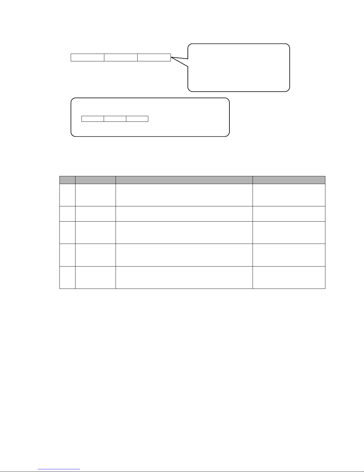
●Transmission Sequences 5-30
5.3.9 Remote Operation Transmission
5.3.9-1 Text
ESC2 Header 72H Type
Type
30H:Operation start
31H:Operation stop
32H:Deflection voltage control (ON)
33H:Deflection voltage control (OFF)
34H:Fault clear
ESC Header 71H Type
[Existing machine message] Existing machine message can also be used.
5.3.9-2 Types of control
Types of control for operation
No. Ty pe Content Function enabled status
1 Operation start
Starts to jet ink, and shifts from stop status to ready
status.
(Same process as with <Startup> button)
Stop status
2 Operation stop
Stops ink jet, and shifts to stop status (Same process as
with <Shutdown> button)
When ink is being jetted
(standby, ready status, etc.)
3
Deflection
voltage control
(ON)
Turns deflection voltage on
(Same process as with <Ready> button in Manual
control menu window)
Standby status
4
Deflection
voltage control
(OFF)
Turns deflection voltage off
(Same process as with <Standby> button in Manual
control menu window)
Ready status
5 Fault clear
Closes the window for any fault that has occurred.
However, the window will remain if the cause of fault
is not resolved.
When fault has occurred
● Specify only one category of control at a time.
● Even if executing function is not possible, ACK will be answered, but no function will be executed.
Page 77
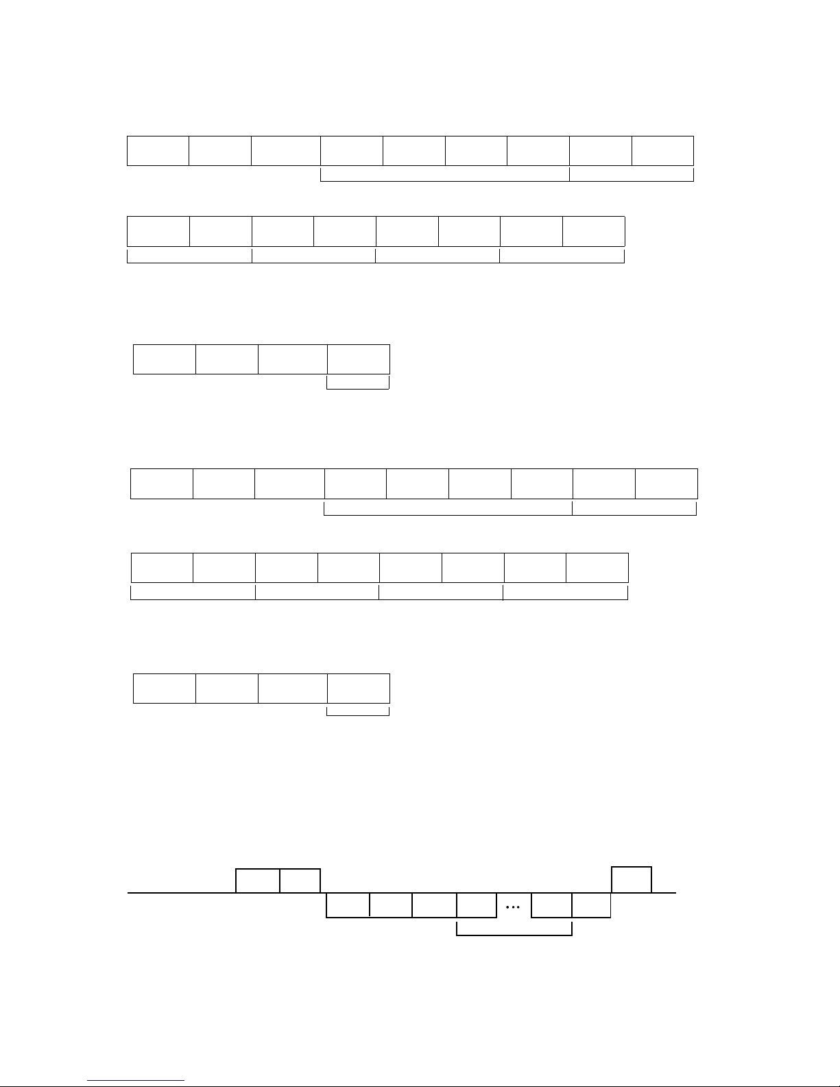
5-31 ●Transmission Sequences
5.3.10 Time control
5.3.10-1 Text
(1) Date/time setup transmission
● Current time
ESC2
Header
2EH
Classification
31H
1000s
place
100s
place
10s
place
Units
place
10s
place
Units
place
Year
Month
10s
place
Units
place
10s
place
Units
place
10s
place
Units
place
10s
place
Units
place
Day
MinutesHour Second
● Calendar time control
ESC2
Header
2EH
Classification
32H
Control
type
● Calendar time
ESC2
Header
2EH
Classification
33H
1000s
place
100s
place
10s
place
Units
place
10s
place
Units
place
Year
Month
(Contd.)
10s
place
Units
place
10s
place
Units
place
10s
place
Units
place
10s
place
Units
place
Day
MinutesHour Second
● Clock system
ESC2
Header
2EH
Classification
34H
Control
type
(2) Current time output transmission
Outputs current time of IJ printer internal calendar.
ESC2
Header
ACK
External device
IJ printer
75H
STX
ESC2
Header
7FH
Yaer
Second
ETX
(Contd.)
Control type (31H: Same as current time; 32H: Clock stop)
Control type (31H: 24-hour system; 32H: 12-hour system)
Year / month / day / hour / minute / second / 14 digits
Page 78
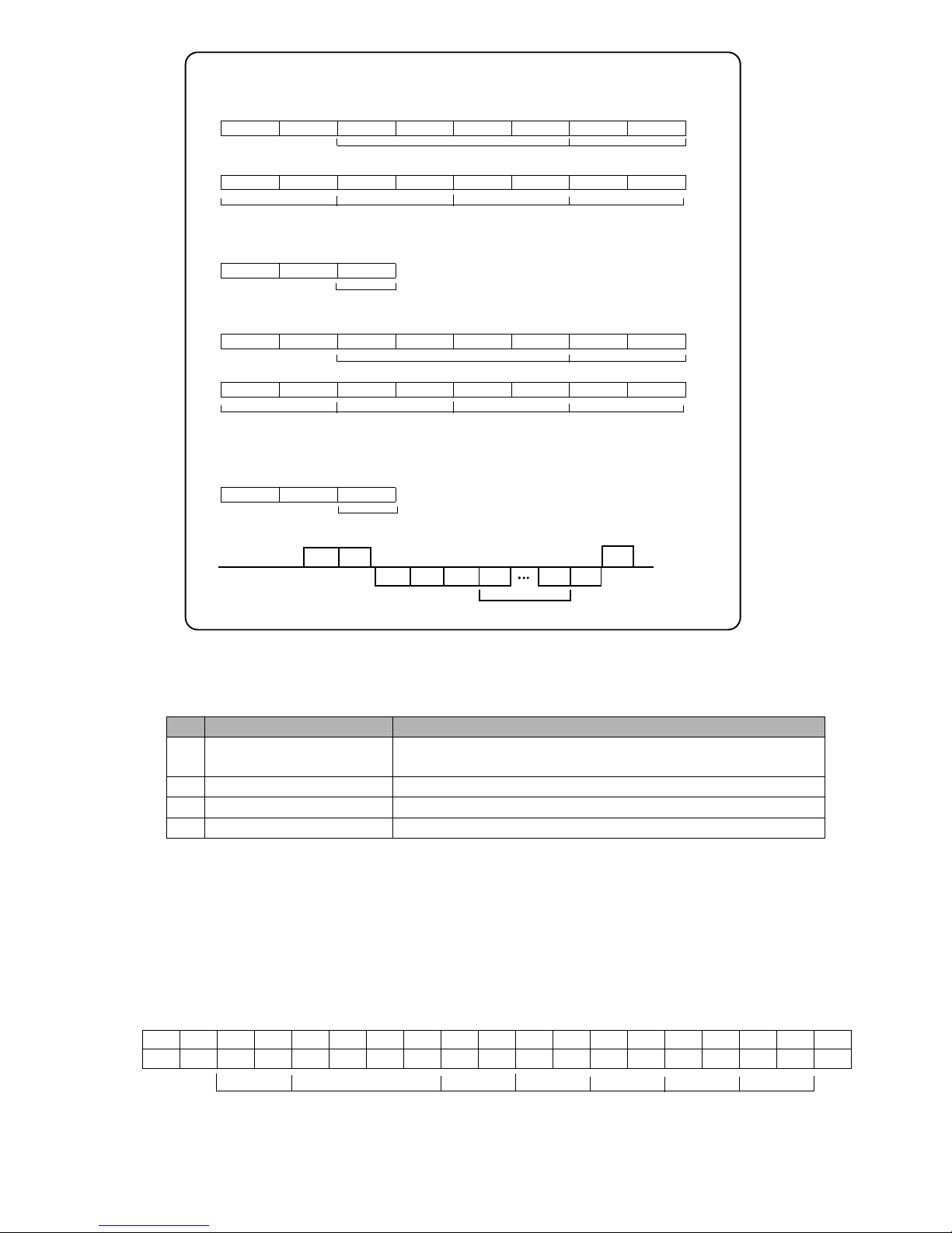
●Transmission Sequences 5-32
ESC Header 72H 1000s place 100s place 10s place Units place 10s place Units place
● Current date/time
(Contd.)
10s place Units place 10s place Units place 10s place Units place 10s place Units place
Yaer Month
Day Hour
Minutes
Second
ESC Header 73H control type
● Calendar time control
control type (31H:Same as current time, 32H:Clock stop)
ESC Header 74H 1000s place 100s place 10s place Units place 10s place Units place
● Calendar time
(Contd.)
10s place Units place 10s place Units place 10s place Units place 10s place Units place
Yaer
Month
Day Hour
Minutes
Second
ESC Header 75H control type
● Clock system
control type (31H:24-hour system, 32H:12-hour system)
ESC2
Header
ACK
External device
IJ printer
7BH
STX
ESC
Header
7CH
Yaer
Second
ETX
Year / month / day / hour / minute / second / 14 digits
5.3.10-2 Date/time setup
(1) This function allows operator to set each item on "Date/time setup screen" for Maintenance menu.
No. Setting item Setting contents
1 Current time
Current date time displayed across the very top of screen
(year/month/day/hour/minute/second)
2 Calendar time control Same as current time, clock stopped
3 Calendar time Time reflected in calendar characters of print contents
4 Clock system 24/12-hour system
(2) After receiving date and time setting transmission, the print contents calendar characters and current time
display are updated.
(3) When transmitting "calendar time", first transmit the message for "calendar time: clock stop":
Simultaneous transmission is also possible.
(4) When changing the calendar time control from "clock stop" to "same as current time", the values on
calendar time will not be saved.
5.3.10-3 Example of time control transmission
(1) Example of setting current time
02H 1FH 2EH 31H 32H 30H 31H 35H 30H 37H 30H 37H 31H 32H 34H 35H 30H 30H 03H
STX
ESC2
. 120120707124500ETX
Yaer
Month
Day
Hour
Minutes Second
[Existing machine message] Existing machine message can also be used.
Header, classification
[Transmission results]
Set current time to 2015/07/07, 12:45:00.
(1) Date/time setup transmission
(2) Current time output transmission
Page 79
5-33 ●Code tables
5.4 Code Tables
5.4.1 Code Tables
(1)Transmission control
ASCII Name Description
02H
STX
(start)
Code that is transmitted immediately before text.
03H
ETX
(end)
Code that is transmitted immediately after text.
05H
ENQ
(enquiry)
This enquiry code is used when the external device checks whether
the IJ printer is ready for signal reception. This code must be
transmitted before data transmission to the IJ printer. When the IJ
printer is ready for reception, the "ACK" code is transmitted after
ENQ code reception. If the IJ printer is not ready for reception, the
"NAK" code is transmitted.
06H
ACK
(acknowledgment)
When the IJ printer is ready for reception, it transmits this code in
response to an "ENQ" code reception from the external device.
This code reports that text reception is normally completed.
0EH
SO
(shift out)
When the 1-byte transmission mode prevails, this code is positioned
at the end of 2-byte code for transmission purposes.
0FH
SI
(shift in)
When the 1-byte transmission mode prevails, this code is positioned
at the beginning of 2-byte code for transmission purposes.
10H
DLE
(start of item)
This code is positioned at the beginning of printings for each print
item for transmission purposes.
12H
DC2
(retransmission)
This code is transmitted if the printings need to be changed before
the printing of the contents transmitted to the IJ printer while the
overwrite-protected mode prevails. After receipt of this code, the
IJ printer transmits the ACK code and becomes ready for reception.
However, if the IJ printer is off-line, the "NAK" code is transmitted.
13H
DC3
(retransmission)
The same as DC2.
However, when receiving DC3, the IJ printer terminates printing
forcibly.
15H
NAK
(negative
acknowledgment)
The IJ printer transmits this code if it is not ready for reception
when it receives the "ENQ" code from the external device.
This code reports that text reception is not normally completed
(when, for instance, the received data is in transmission error or
an unregistered print data number is received)
1BH
ESC
(start of header)
This code is positioned at the beginning of a header for transmission purposes. The header is a code that recognizes the transmission
data type and is transmitted next to STX.
(Existing machine / message specs.)
1FH
ESC2
(start of header)
This code is positioned at the beginning of a header for transmission purposes. The header is a code that recognizes the transmission
data type and is transmitted next to STX.
2
1
1
2
Page 80
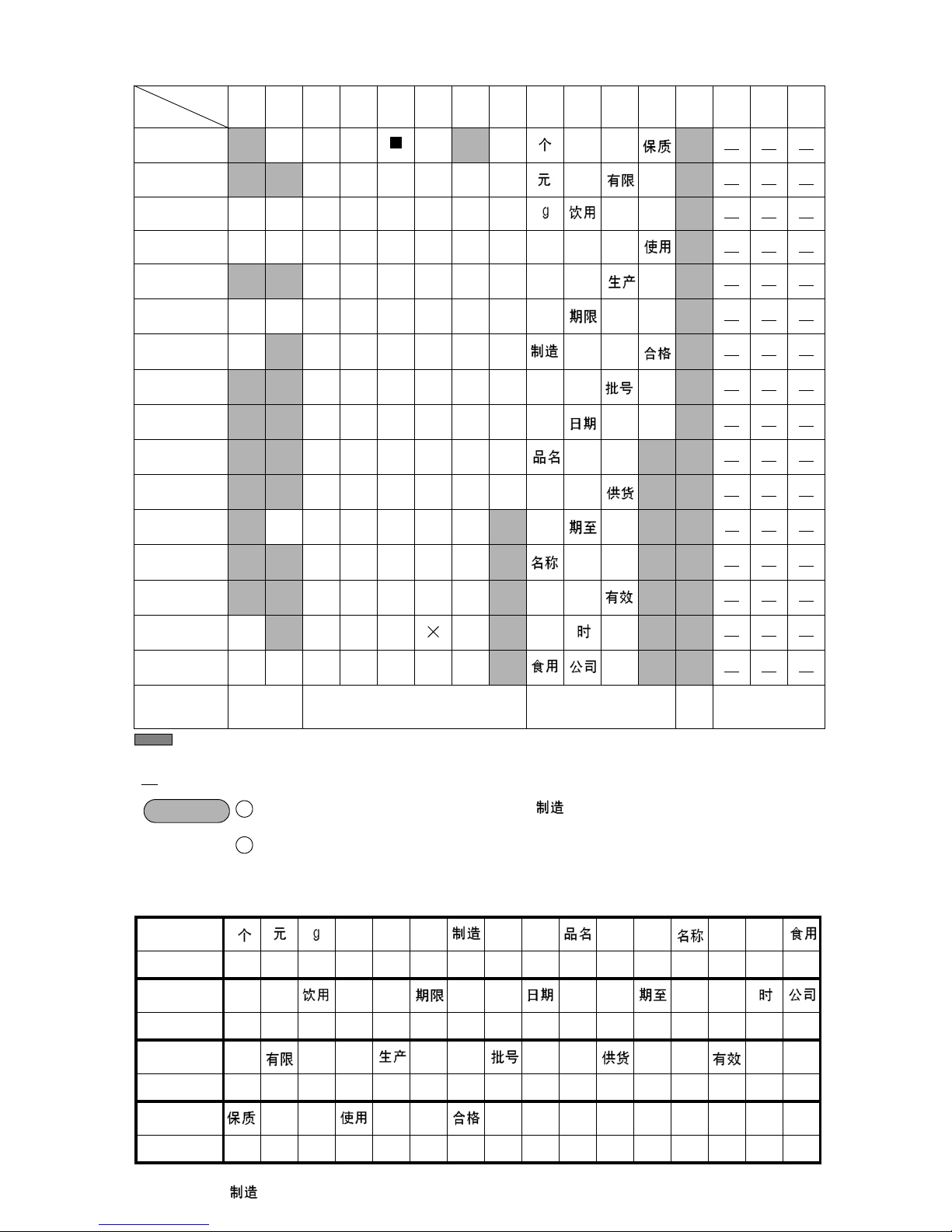
●Code tables 5-34
Dedicated
characters
←← ←← ←←
2-byte code F040 F041 F042 F043 F044 F045 F046 F047 F048 F049 F04A F04B F04C F04D F04E F04F
Dedicated
characters
←← ←← ←← ←← ←←
2-byte code F050 F051 F052 F053 F054 F055 F056 F057 F058 F059 F05A F05B F05C F05D F05E F05F
Dedicated
characters
←←←←←←←←←←←
2-byte code F060 F061 F062 F063 F064 F065 F066 F067 F068 F069 F06A F06B F06C F06D F06E F06F
Dedicated
characters
←← ←← ←←
2-byte code F070 F071 F072 F073 F074 F075 F076 F077 F078
0123456789ABCDEF
0
DLE Space
0Pp
↑
↑ 00 16 32
1 !1AQaq ↑↑01 17 33
2STXDC2 2BRbr ↑↑ 02 18 34
3ETXDC3#3CScs ↑↑ 03 19 35
4 $4DTdt
↑
↑
04 20 36
5 ENQ NAK % 5 E U e u
↑
↑
05 21 37
6ACK &6FV f v
↑
↑
06 22 38
7 7GWgw
↑
↑ ↑
07 23 39
8 (8HXhx
↑
↑ ↑
08 24 40
9 )9IYiy
↑
↑
09 25 41
A *:JZjz
↑
↑
10 26 42
B ESC + ; K [ k
↑ ↑
11 27 43
C ,<L l
↑ ↑
12 28 44
D -=M]m
↑ ↑
13 29 45
ESO .>N n
↑ ↑
14 30 46
FSIESC2/?O_o
↑
15 31 47
Category
Transmi-
ssion
control
Standard characters
Dedicated
characters
User pattern
character
年
月
(2)ASCII codes
High-order
Low-order
: Unusable
↑ : Dedicated character consisting of multiple codes
nn
: User pattern character number
NOTICE
As regards a dedicated character (e.g., (3-code)) consisting of two or more
codes, the text must be created so that it can be contained within a single print item.
As regards a print item for which a bar code is set up, the text must be created in
such a manner that the employed character codes are within the range applicable to
the bar code.
1
2
¥
(3)Dedicated characters (2-byte codes)
←: Dedicated characters consisting of two or more codes.
“ ” consists of three characters (F046, F047, and F048).
“
‘
日 年 月
日
‘
Page 81
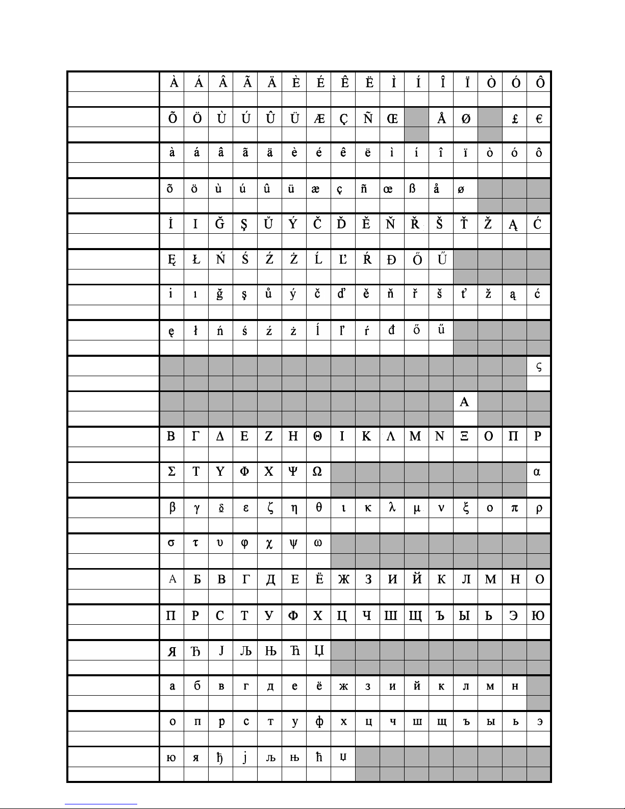
5-35 ●Code tables
Special characters (2-byte codes)
(When special characters can be input)
Characters
Communication code F340 F341 F342 F343 F344 F345 F346 F347 F348 F349 F34A F34B F34C F34D F34E F34F
Characters
Communication code F350 F351 F352 F353 F354 F355 F356 F357 F358 F359 F35B F35C F35E F35F
Characters
Communication code F360 F361 F362 F363 F364 F365 F366 F367 F368 F369 F36A F36B F36C F36D F36E F36F
Characters
Communication code F370 F371 F372 F373 F374 F375 F376 F377 F378 F379 F37A F37B F37C
Characters
Communication code F380 F381 F382 F383 F384 F385 F386 F387 F388 F389 F38A F38B F38C F38D F38E F38F
Characters
Communication code F390 F391 F392 F393 F394 F395 F396 F397 F398 F399 F39A F39B
Characters
Communication code F3A0 F3A1 F3A2 F3A3 F3A4 F3A5 F3A6 F3A7 F3A8 F3A9
F3AA F3AB F3AC F3AD F3AE
F3AF
Characters
Communication code F3B0 F3B1 F3B2 F3B3 F3B4 F3B5 F3B6 F3B7 F3B8 F3B9
F3BA F3BB
Characters
Communication code F29F
Characters
Communication code
F2AC
Characters
Communication code F3C0 F3C1 F3C2 F3C3 F3C4 F3C5 F3C6 F3C7 F3C8 F3C9
F3CA F3CB F3CC F3CD
F3CE F3CF
Characters
Communication code F3D0 F3D1 F3D2 F3D3 F3F4 F3D5 F3D6 F3DF
Characters
Communication code F3E0 F3E1 F3E2 F3E3 F3E4 F3E5 F3E6 F3E7 F3E8 F3E9
F3EA E3EB E3EC F3ED
F3EE F3EF
Characters
Communication code F3F0 F3F1 F3F2 F3F3 F3F4 F3F5 F3F6
Characters
Communication code F540 F541 F542 F543 F544 F545 F546 F547 F548 F549 F54A F54B F54C F54D F54E F54F
Characters
Communication code F550 F551 F552 F553 F554 F555 F556 F557 F558 F559 F55A F55B F55C F55D F55E F55F
Characters
Communication code F560 F561 F562 F563 F564 F565 F566
Characters
Communication code F570 F571 F572 F573 F574 F575 F576 F577 F578 F579 F57A F57B F57C F57D F57E
Characters
Communication code F580 F581 F582 F583 F584 F585 F586 F587 F588 F589 F58A F58B F58C F58D F58E F58F
Characters
Communication code F590 F591 F592 F593 F594 F595 F596 F597
Page 82
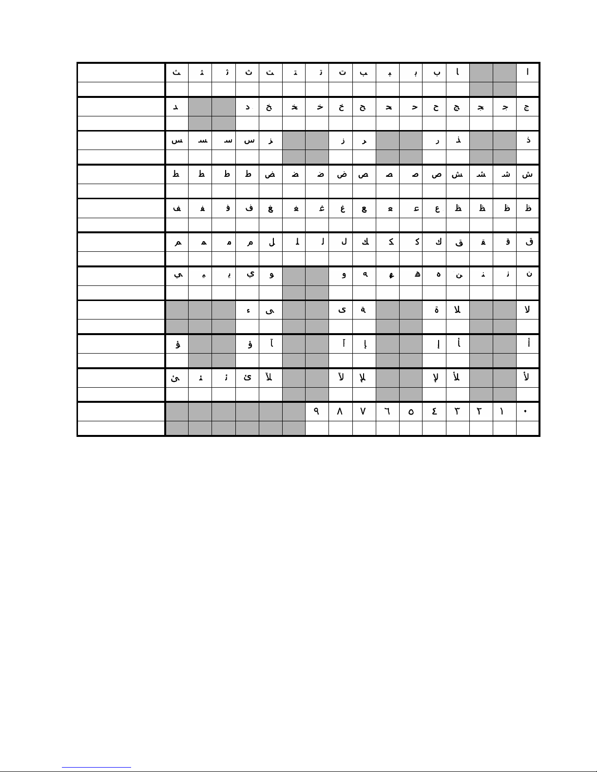
●Code tables 5-36
Arabic characters (2-byte codes)
Characters
Communication code F44D F44C F44B F44A F449 F448 F447 F446 F445 F444 F443 F442 F441 F440
Characters
Communication code F45B F45A F459 F458 F457 F456 F455 F454 F453 F452 F451 F450 F44F F44E
Characters
Communication code F465 F464 F463 F462 F461 F460 F45F F45B F45D F45C
Characters
Communication code F475 F474 F473 F472 F471 F470 F46F F46E F46D F46C F46B F46A F469 F468 F467 F466
Characters
Communication code F485 F484 F483 F482 F481 F480 F47F F47E F47D F47C F47B F47A F479 F478 F477 F476
Characters
Communication code F495 F494 F493 F492 F491 F490 F48F F48E F48D F48C F48B F48A F489 F488 F487 F486
Characters
Communication code F4A3 F4A2 F4A1 F4A0 F49F F49E F49D F49C
F49B F49A F499 F498 F497
F496
Characters
Communication code
F4AA
F4A9 F3A8 F4A7
F4A6
F4A5 F4A4
Characters
Communication code F4B2 F4B1 F4B0 F4AF
F4AE F4AD F4AC F4AB
Characters
Communication code
F4BC F4BB F4BA
F4B9 F4B8 F4B7 F4B6 F4B5
F4B4
F4B3
Characters
Communication code F4C6 F4C5 F4C4 F4C3
F4C2 F4C1 F4C0 F4BF
F4BE
F4BD
Page 83
5-37 ●Code tables
(4)User pattern characters (2-byte codes)
Fixed size
User pattern
character
00 01 02 03 04 05 06 07 08 09 10 11 12 13 14 15
2-byte code F140 F141 F142 F143 F144 F145 F146 F147 F148 F149 F14A F14B F14C F14D F14E F14F
User pattern
character
16 17 18 19 20 21 22 23 24 25 26 27 28 29 30 31
2-byte code F150 F151 F152 F153 F154 F155 F156 F157 F158 F159 F15A F15B F15C F15D F15E F15F
User pattern
character
32 33 34 35 36 37 38 39 40 41 42 43 44 45 46 47
2-byte code F160 F161 F162 F163 F164 F165 F166 F167 F168 F169 F16A F16B F16C F16D F16E F16F
User pattern
character
48 49 50 51 52 53 54 55 56 57 58 59 60 61 62 63
2-byte code F170 F171 F172 F173 F174 F175 F176 F177 F178 F179 F17A F17B F17C F17D F17E F17F
User pattern
character
64 65 66 67 68 69 70 71 72 73 74 75 76 77 78 79
2-byte code F180 F181 F182 F183 F184 F185 F186 F187 F188 F189 F18A F18B F18C F18D F18E F18F
User pattern
character
80 81 82 83 84 85 86 87 88 89 90 91 92 93 94 95
2-byte code F190 F191 F192 F193 F194 F195 F196 F197 F198 F199 F19A F19B F19C F19D F19E F19F
User pattern
character
96 97 98 99 A0 A1 A2 A3 A4 A5 A6 A7 A8 A9 B0 B1
2-byte code F1A0 F1A1 F1A2 F1A3 F1A4 F1A5 F1A6 F1A7 F1A8 F1A9
F1AA F1AB F1AC F1AD F1AE F1AF
User pattern
character
B2 B3 B4 B5 B6 B7 B8 B9 C0 C1 C2 C3 C4 C5 C6 C7
2-byte code F1B0 F1B1 F1B2 F1B3 F1B4 F1B5 F1B6 F1B7 F1B8 F1B9
F1BA F1BB F1BC F1BD F1BE F1BF
User pattern
character
C8 C9 D0 D1 D2 D3 D4 D5 D6 D7 D8 D9 E0 E1 E2 E3
2-byte code F1C0 F1C1 F1C2 F1C3 F1C4 F1C5 F1C6 F1C7 F1C8 F1C9
F1CA F1CB F1CC F1CD F1CE F1CF
User pattern
character
E4 E5 E6 E7 E8 E9 F0 F1 F2 F3 F4 F5 F6 F7 F8 F9
2-byte code F1D0 F1D1 F1D2 F1D3 F1D4 F1D5 F1D6 F1D7 F1D8 F1D9
F1DA F1DB F1DC F1DD F1DE F1DF
User pattern
character
G0 G1 G2 G3 G4 G5 G6 G7 G8 G9 H0 H1 H2 H3 H4 H5
2-byte code F1E0 F1E1 F1E2 F1E3 F1E4 F1E5 F1E6 F1E7 F1E8 F1E9
F1EA F1EB F1EC F1ED F1EE F1EF
User pattern
character
H6 H7 H8 H9 I0 I1 I2 I3 I4 I5 I6 I7 I8 I9 J0 J1
2-byte code F1F0 F1F1 F1F2 F1F3 F1F4 F1F5 F1F6 F1F7 F1F8 F1F9
F1FA F1FB F1FC F1FD F1FE F1FF
User pattern
character
J2 J3 J4 J5 J6 J7 J8 J9
2-byte code F220 F221 F222 F223 F224 F225 F226 F227
User pattern character display scheme
00
,01 09 (0 to 9)
10
,11 19 (10 to 19)
:
90
,91 99 (90 to 99)
A0
,A1 A9 (100 to 109)
:
J0
,J1 J9 (190 to 199)
… … … … … … … … …
…
Page 84
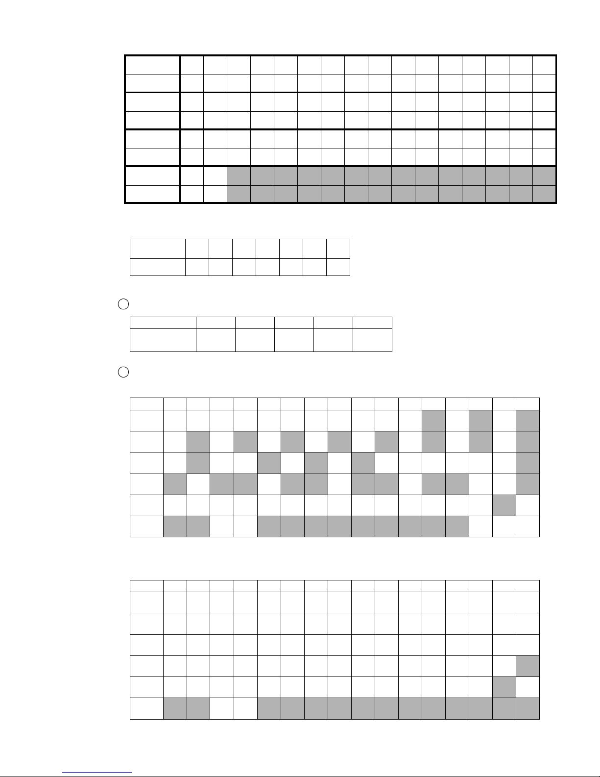
●Code tables 5-38
(5)Punctuation characters (2-byte codes)
Punctuation
character
‘.:,
Space
;!
2-byte code F240 F241 F242 F243 F244 F245 F246
(6)Katakana (when KANA and dedicated characters can be input)
Available character sizes
5x8 7x10 10x12 12x16 18x24
Inter-character
space (dots)
1 to 31246
Character codes table (2-byte code)
(1)Character size 5x8, 7x10
0123456789ABCDEF
834*
835*
836*
837*
838*
839*
ァ ア ィ イ ゥ
ウ
ェ エ ォ オ カ キ ク ケ コ サ シ ス セ ソ タ チ ッ ツ
テ
ト
ナ
ニ ヌ ネ
ノ ハ ヒ
フ ヘ ホ
マ
ミ
ム メ モ
ャ ヤ ュ
ユ
ョ ヨ ラ
リ ル レ ロ ワ
ヲ ン ー
゛
゜
(2)Character size 10x12, 12x16, 18x24
0123456789ABCDEF
834*
835*
836*
837*
838*
839*
ァ ア ィ イ ゥ
ウ
ェ エ ォ オ カ キ
ク
ケ コ サ シ ス セ ソ タ チ ッ ツ テ ト ナ ニ ヌ ネ ノ ハ ヒ フ ヘ ホ
マ ミ ム メ モ ャ ヤ
ュ ユ ョ ヨ ラ
リ ル レ ロ ワ ヲ ン
ガ ギグ
ゲ ゴ ザ ジ ズ ゼ ゾ ダ ヂ ヅ デ ド パ ピ プ
ペ
ポ
バ ビ ブ ベ ボ
1
2
Character code of long “ “ is 815B.
ー
User pattern
character
00 01 02 03 04 05 06 07 08 09 10 11 12 13 14 15
2-byte code F640 F641 F642 F643 F644 F645 F646 F647 F648 F649 F64A F64B F64C F64D F64E F64F
User pattern
character
16 17 18 19 20 21 22 23 24 25 26 27 28 29 30 31
2-byte code F650 F651 F652 F653 F654 F655 F656 F657 F658 F659 F65A F65B F65C F65D F65E F65F
User pattern
character
32 33 34 35 36 37 38 39 40 41 42 43 44 45 46 47
2-byte code F660 F661 F662 F663 F664 F665 F666 F667 F668 F669 F66A F66B F66C F66D F66E F66F
User pattern
character
48 49
2-byte code F670 F671
Free size
Page 85
5-39 ●Code tables
(7)Calendar character code
● Set "calendar block starting character"as the first character and set "calendar block ending charater" as
the last character.
Yaer Month Day Hour Minute Second
Total number
of days
Weeks
Day of
week
Calendar character F250 F251 F252 F253 F254 F255 F256 F258 F259
Calendar block start chracter F260 F261 F262 F263 F264 F265 F266 F268 F269
Calendar block end chracter F270 F271 F272 F273 F274 F275 F276 F278 F279
Specified number of digits for calendar characters
Calendar character Specified number of digits
Yaer 1 to 4 digits
Month 1 to 3 digits
Day 1 to 3 digits
Hour 1 to 2 digits
Minute 1 to 2 digits
Second 1 to 2 digits
Total number of days 1 to 3 digits
Weeks 1 to 3 digits
Day of week 1 to 3 digits
Y Y M M D D
Calendar block end character
Calendar character
Calendar block start character
Calendar block
Calendar character is 2-byte code only.
Example of when performing printings transmission of calendar character
(Example 1) Example of when setting a calendar block to print item 1
02H 10H 31H 0FH F2H 60H F2H 50H F2H 51H F2H 71H 0EH 03H
STX DLE 1 SI Start chracter Calendar Calendar End chracter SO ETX
Calendar block
Print item1
YYMM
: Calendar block range
YM
: Calendar character “Year, Month”
[Transmission results]
(Example)
Page 86
●Code tables 5-40
(8)Count character code
● Set "count block starting character"as the first character and set "count block ending charater" as the
last character.
Count character Count block start character Count block end character
F25A F26A F27A
(Example 2) Example of when setting 2 calendar blocks to print item 1
02H 10H 31H 0FH F2H 60H F2H 50H F2H 51H F2H 51H F2H 52H F2H 72H 0EH
STX DLE 1 SI
Start
chracter
Calendar Calendar Calendar Calendar
End
chracter
SO
(Contd.)
Calendar block 1
41H 42H 43H 0FH F2H 62H F2H 52H F2H 53H F2H 73H 0EH 03H
ABCSI
Start
chracter
Calendar Calendar
End
chracter
SO ETX
Calendar block 2
Print item1
YYMMDD
: Calendar block range
YMDH
: Calendar character “Year, Month,
02H 10H 31H 0FH F2H 50H F2H 50H F2H 51H F2H 51H 0EH 03H
STX DLE 1 SI Calendar Calendar Calendar Calendar SO ETX
Calendar block
Print item1
YYMM
: Calendar block range
YM
: Calendar character “Year, Month”
Count block end character
Count character
Count block start character
Count block
C C C C C CC C C C C C
C
: Count character
Count character is 2-byte code only.
AND DDHH
Day, Hour”
[Transmission results]
[Existing machine message] Existing machine message can also be used.
[Transmission results]
(Example)
Page 87
5-41 ●Code tables
Example of when performing printings transmission of count character
(Example 1)Example of when setting a count block to print item 1
02H10H 31H0FHF2H6AHF2H5AHF2H5AHF2H7AH0EH 03H
STX DLE 1 SI Start chracter Count Count End chracter SO ETX
Count block
Print item1
C C C C
: Count block range
C
: Count character
(Example 2)Example of when setting 2 count blocks to print item 1
02H 10H 31H 0FH F2H 6AH F2H 5AH F2H 5AH F2H 5AH F2H 5AH F2H 7AH 0EH
STX DLE 1 SI
Start
chracter
Count Count Count Count
End
chracter
SO
(Contd.)
Count block 1
41H 42H 43H 0FH F2H 6AH F2H 5AH F2H 5AH F2H 7AH 0EH 03H
ABCSI
Start
chracter
Count Count
End
chracter
SO ETX
Count block 2
Print item1
C C C C C C
: Count block range
C
: Count character
ABC
C C C C
02H 10H 31H 0FH F2H 5AH F2H 5AH F2H 5AH F2H 5AH 0EH 03H
STX DLE 1 SI Count Count Count Count SO ETX
Countr block
Print item1
C C C C
: Count block range
C
: Count character
[Transmission results]
[Transmission results]
[Transmission results]
[Existing machine message] Existing machine message can also be used.
Page 88
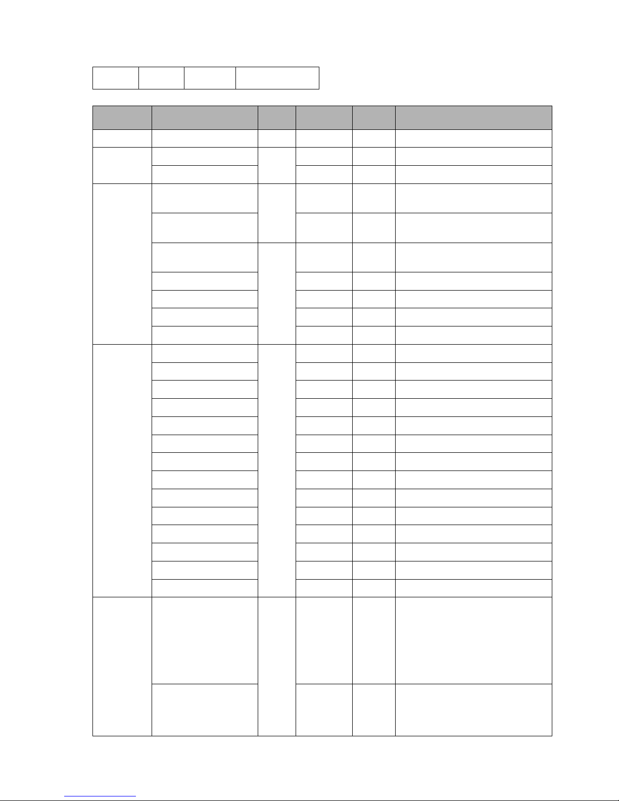
●Code tables 5-42
Type Header Classification
Data
count
Data section
Recall Message number 20H 31H 4 0001 to 2000
Registration
Message number
21H
31H 4 0001 to 2000
Message name 32H 1 to 12 Message name: Max 12 digits
Print format
Line count, print format
uniformity
22H
31H 0 -
Line count/Line spacing 32H 2
Line count : 1 to 5
Line spacing: 0 to 2
Character size/
inter character space
23H
31H 3
Character size : 30H to 3CH
Inter character space : 00 to 28
Increased width 32H 1 1 to 9
Bar code 33H 1 30H to 44H
Readable code 34H 1 0 to 2
Prefix Code 35H 2 00 to 99
Print
specifications
Character height
25H
31H 2 00 to 99
Ink drop use percentage 32H 2 01 to 16
High-speed printing 33H 1 0 to 2
Character width 34H 4 0000 to 3999
Character orientation 35H 1 0 to 3
Print start delay 36H 4 0000 to 9999
Print start delay (reverse) 37H 4 0000 to 9999
Product speed matching 38H 1 0 to 1
Pulse rate division Factor 39H 3 001 to 999
Repeat count 3DH 4 0000 to 9999
Repeat intervals 3EH 5 00000 to 99999
Target sensor timer 3FH 3 000 to 999
Target sensor filter 40H 1 1 to 2
Target sensor filter value 41H 4 0000 to 9999
Calendar
condition
Offset
(Year / month / day / hour /
minute)
28H
32H 6
Calendar block : 1 to 8
Type : 0 to 4
Offset : Yaer 0000 to 0099
Month 0000 to 0099
Day 0000 to 1999
Hour -023 to 0099
Minute -059 to 0099
Zero suppress usage
(Year / month / day / hour /
minute / week /
Day of week)
34H 3
Calendar block : 1 to 8
Type : 0 to 6
Mode : 0 to 2
5.4.2 Header Table
ESC2 Header Classification
Page 89
5-43 ●Code tables
Type Header Classification
Data
count
Data section
Count
condition
Initial value
2CH
31H Variable
Count block : 1 to 8
Initial value : max 20 digits
Range 1 32H Variable
Count block : 1 to 8
Range 1 : max 20 digits
Range 2 33H Variable
Count block : 1 to 8
Range 2 : max 20 digits
Update (in progress) 34H 7
Count block : 1 to 8
Update (in progress) : 000000 to 999998
Update (unit) 35H 7
Count block : 1 to 8
Update (unit) : 000001 to 999999
Increment 36H 3
Count block : 1 to 8
Increment : 01 to 99
Direction 37H 2
Count block : 1 to 8
Direction : 0 to 1
Jump from 38H Variable
Count block : 1 to 8
Jump from : max 20 digits
Jump to 39H Variable
Count block : 1 to 8
Jump to : max 20 digits
Reset 3AH Variable
Count block : 1 to 8
Reset : max 20 digits
Reset signal 3BH 2
Count block : 1 to 8
Reset signal : 0 to 1
External signal count 3EH 2
Count block : 1 to 8
External count : 0 to 1
Date/time
setup
Current time
2EH
31H 14
Yaer, Month, Day, Hour, Minute,
Second (14 digits)
Calendar time control 32H 1 1 to 2
Calendar time 33H 14
Yaer, Month, Day, Hour, Minute,
Second (14 digits)
Clock system 34H 1 1 to 2
User pattern
character
transmission
Character size fixed
pattern
32H 30H to 3CH - Character code + pattern data
Other
Item No. specification 70H Item No. - Used together with print format message
Remote opearation 72H 30H to 34H -
Online 73H - - No STX/ETX
Offline 74H - - No STX/EXT
Current time inquiry 75H - - No STX/ETX; Inquiry
Communication buffer
Claer buffer
76H - -
Communication buffer
Reset printing
77H - -
Current time output 7FH - 14
Yaer, Month, Day, Hour, Minute,
Second (14 digits)
Page 90
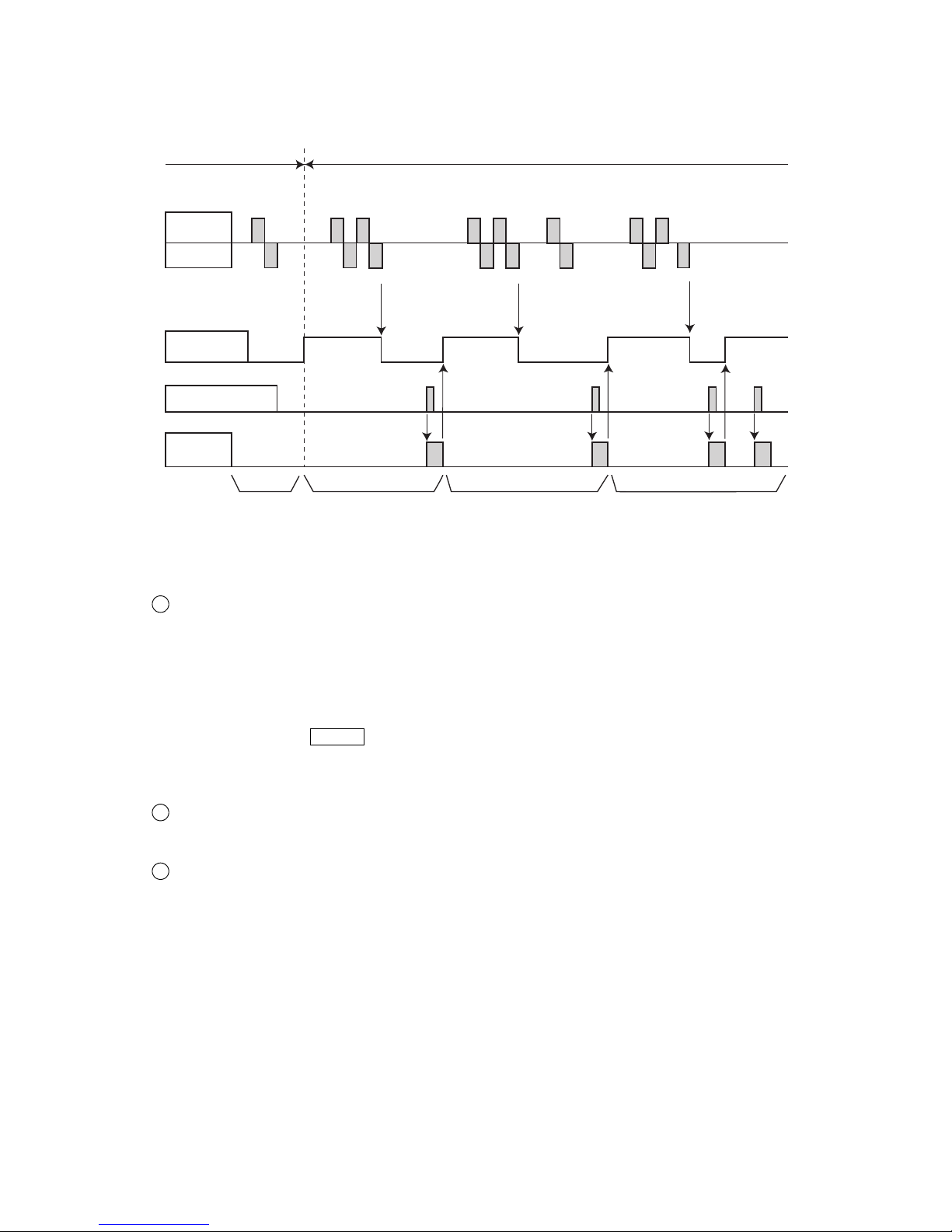
●Communication Timing 5-44
ENQENQ
NAK
ETX
STX
ACK ACK
ENQ ETX
STX
ENQ ETX
STX
ENQ
ACK ACK ACK ACKNAK
External
device
IJ printer
Print start signal
Readiness
for reception
(No signal output)
Not ready
for
reception
Ready for
reception
Printing
operation
ABC
C
On-line
Off-line
(a) (b) (c) (d)
AB
C
5.5 Communication Timing
5.5.1 Signal Timing
(1)In overwrite-protected mode
(a) When the IJ printer is off-line
● The NAK code is transmitted in response to an ENQ code reception from the outside.
(b) When the IJ printer is on-line
When transmitting printing only
● Transmission data is received from the external device. When the received data is not in error, the ACK
code is transmitted and the "not ready for reception" state prevails.
● To switch from the "not ready for reception" state to the "ready for reception" state, perform one of the
following procedures.
1) Perform a printing operation once.
2) Transmit the DC2 (retransmission) code to the IJ printer.
3) Press the Comm On/Off buttun to enter the off-line mode, and then switch back to the on-line mode.
● If the data transmitted from the external device is in error, the NAK code is transmitted after receipt of
the ETX code.
Since the "ready for reception" state is maintained in this instance, retransmit the data beginning.
When transmitting print conditions, user pattern characters, and print data recall
● When the data received from the external device is not in error, the ACK code is transmitted. In this
instance, the "ready for reception" state is maintained.
When transmitting printing, print conditions, user pattern characters, and print data recall
● When transmitting printing, print conditions, user pattern characters, and print data recall, ensure that the
print conditions, user pattern characters, and print data recall are transmitted prior to the printing. If the
printing is transmitted earlier than the other data, the "not ready for reception" state prevails.
Therefore, the subsequent transmission of the print conditions, user registration characters, and print data
recall causes a communication error.
(c) When the "not ready for reception" state prevails after transmission data reception
from the external device
● The NAK code is transmitted in response to the ENQ code reception from the outside.
(d) Transmission data received from the external device
● Error-free transmission data is stored in the IJ printer. The same contents are printed until different
transmission data is transmitted to the IJ printer.
● If the data transmitted from the external device is in error, the IJ printer printings remain unchanged.
In such an instance, retransmit the data beginning as explained in (b).
The retransmission count setup must be determined from the device side.
2
1
3
Page 91
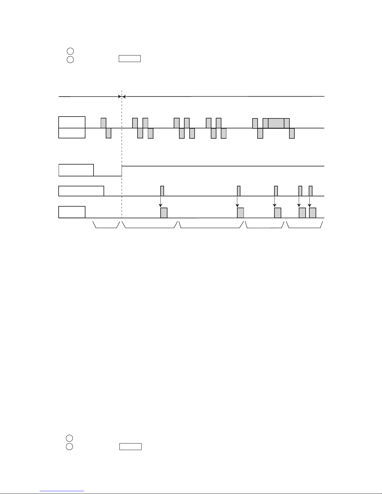
5-45 ●Communication Timing
Print start signal
Readiness
for reception
(No signal output)
Not ready
for
reception
Printing
operation
A
C
C
D
On-line
Off-line
(a) (b) (c)
(d)
D
Ready for
reception
(e)
ENQENQ
NAK
ETX
STX
ACK ACK
ENQ ETX
STX
ENQ
ETX
STX
ENQ
ACK ACK
ACK
ACK
External
device
IJ printer
A
B
ACK ACK
ETX
STX
B
C
D
DATA
(e) When a data transmission is aborted (the transmission of up to the ETX
● The IJ printer printings remain unchanged. For data retransmission, perform either of the following
procedures.
Transmit the DC2 (retransmission) code to the IJ printer.
Press the Comm On/Off buttun to enter the off-line mode, and then switch back to the on-line mode.
1
2
(2) In overwrite-enabled mode
(a) When the IJ printer is off-line
● The NAK code is transmitted in response to an ENQ code reception from the outside..
(b) When the IJ printer is on-line
● Transmission data is received from the external device. When it contains no error, the ACK code is
transmitted. In this instance, the "ready for reception" state is maintained.
● If the data transmitted from the external device is in error, the NAK code is transmitted after receipt of
the ETX code.
In this instance, retransmit the data beginning.
(c) Data retransmission
● Transmission data is received from the external device, and subsequent transmission data is accepted.
In this case, the received data is accepted even if the DC2 (retransmission) code is not attached.
(d) Printing during reception
● While data is being received from the external device, the previously printed contents are printed.
(e) Transmission data received from the external device
● Error-free transmission data is stored in the IJ printer. The same contents are printed until different
transmission data is transmitted to the IJ printer.
(f) When a data transmission is aborted
(the transmission of up to the ETX code is not completed)
● The IJ printer printings remain unchanged. For data retransmission, perform either of the following
procedures.
Transmit the DC2 (retransmission) code to the IJ printer.
Press the Comm On/Off buttun to enter the off-line mode, and then switch back to the on-line mode.
1
2
Page 92
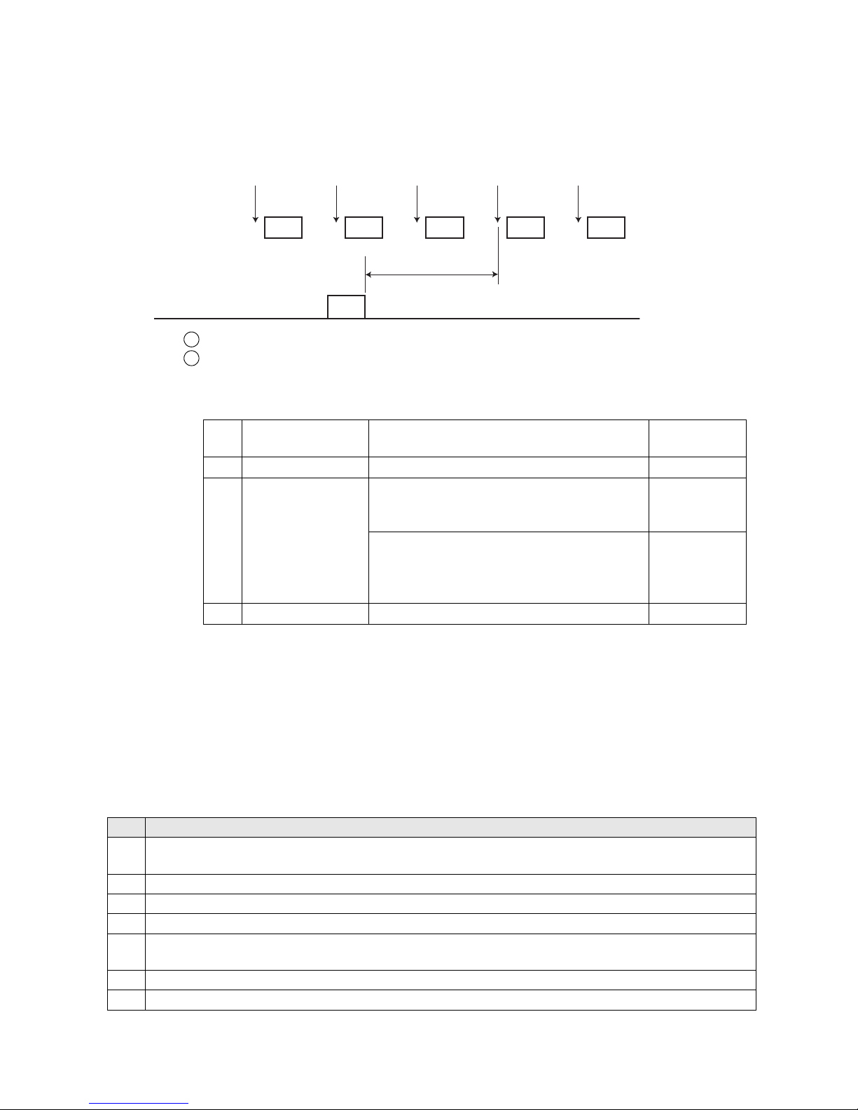
●Communication Timing 5-46
(b) Restrictions
Perform communications only under the conditions shown below. If even one of these conditions is not met, any
input to print target detector while the communicated contents are being printed will cause fault "Print data
changeover in progress M" to occur.
Conditions that the print target detector input will not cause an abnormality
Printing
ABC ABC DEF
Switching
ABC
DEF
Communication
Print target
detector
Print target
detector
Print target
detector
Print target
detector
Print target
detector
DEF
(3) Switching print data with no occurrence of fault "Print data changeover in progress M"
The following shows the method of use with no occurrence of "Print data changeover in progress M" when
switching the print contents during transmission:
(a) Print timing schematic diagram
The IJ printer receives contents "DEF" in communication while printing contents "ABC".
The IJ printer switches printing to the received contents: It will print the previous data during
switching.
1
2
No. Conditions
1
Make sure that none of the following software options are provided:
Barcode Reader Connection (SOP-08)
2 Set the Print data changeover on User environment setup screen to "Disable".
3 Set the Communication mode on Communication environment setup screen to "overwrite-enabled".
4 Set the Buffer function on Communication environment setup screen to "Disable".
5
Transmit print contents independently, and do not package print content transmission with print
condition transmission.
6 Transmit to print items with no count block.
7 Do not transmit the count characters.
Switching time
No. Transmission type Conditions
Maximum time
(ms)
1 Print description - 100
2 Print data recall
When the character height, character width,
character orientation, ink drop use percentage,
or print format changes before or after recall.
500
When the character height, character width,
character orientation, ink drop use percentage,
or print format does not change before or after
recall.
100
3 Print conditions - 500
● The fewer characters, the shorter the time.
● The fewer different time of the print format, the shorter the time.
Page 93
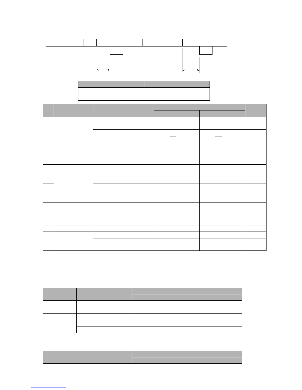
5-47 ●Communication Timing
No. Transmission type Conditions
T1 Maximum time (ms)
Remarks
Within 24 items 25 items or more
1 Print description
The print message transfer
ACK condition is t=fixed.
10 45 *1
The print message transfer
ACK condition is t=async.
(M: Number of
communication
characters)
(M: Number of
communication
characters)
*1 *2
*4
2 Print data recall - 5 30
3
Print data
registration
-18001800
4
Print conditions
Print specifications 10 10
5 Print format 20 50
6
Line conut /
print format uniformity
20 50
7
User pattern
character
-
M+10
(M: Number of
communication
patterns)
M+10
(M: Number of
communication
patterns)
8 Date/time setup - 5 5 *3
9 Remote operation
Operation stop 20 20
Operation start, deflection
voltage control, error reset
15 15
Externaldevice
IJprinter
ENQ
ACK
STX ETX
ACK
………
T0
T1
5.5.2 Response Time
(1) Time interval (T1) between external device communication and IJ printer response
Baud rate (bps) T0 Maximum time (ms)
150 to 1200 5
2400 to 115200 1
*1 For "t=fixed" and "t=async.", see Section 5.2.1, "Setting Communication Environment ".
*2 When there is a data matrix and QR code setting, the time is as follows:
*3 If time changes just before 3ACK transmission, ACK transmission may be delayed about 20 ms.
*4 When there is a GS1 DataBar setting, the time is as follows:
Time T1 when there is a data matrix and QR code setting
Character size
T1 Maximum time (ms)
Within 24 items 25 items or more
Data matrix
5x8 8x N+20 100
12x16, 18x24 15x N+40 150
QR code
QR (21x21) 200xN 200xN
QR (25x25) 300xN 300xN
QR (29x29) 400xN 400xN
M
10
+25
(N : Number of 2-Dimensional codes)
M
10
+75
Time T1 when there is a GS1 DataBar setting
T1 Maximum time (ms)
Within 24 items 25 items or more
GS1 DataBar 10x N+5 10x N+15
(N : Number of GS1 DataBar)
Page 94
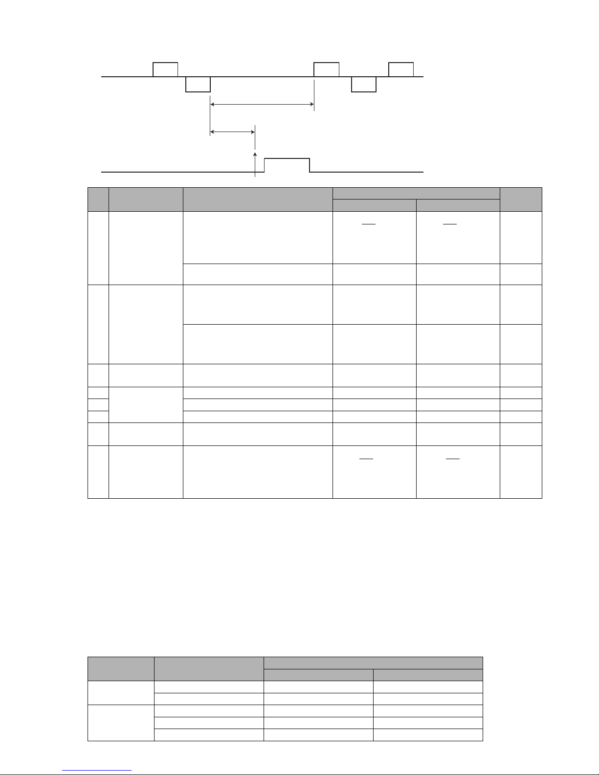
●Communication Timing 5-48
No. Transmission type Conditions
T2 Minimum time (ms)
Remarks
Within 24 items 25 items or more
1 Print description
The print message transfer
ACK condition is t=fixed.
(M: Number of
communication
characters)
(M: Number of
communication
characters)
*6 *9
The print message transfer
ACK condition is t=async.
00
2 Print data recall
When the character height, character
width, character orientation, ink drop
use percentage, or print format changes
before or after recall
400 400 *7
When the character height,
character width, character orientation,
ink drop use percentage, or print format
does not change before or after recall
40 40 *8
3
Print data
registration
-3030
4
Print conditions
Print specifications 400 400 *7
5 Print format 400 400 *7
6 Overall column setup 200 200 *8
7
User pattern
character
-2525
8 Date/time setup -
(M: Number of
printing
characters)
(M: Number of
printing
characters)
*6
External
device
IJprinter
ETX
ACK
STX
ENQ
ACK
5ms(*5)
T2
Printing
operation
Printstartsignal
(2) Time interval (T2) between IJ printer response and printing start
● The IJ printer executes an internal process to make printing preparations in accordance with the received print
data. Do not enter the print start signal during internal process execution.
● In the overwrite-protected mode, initiate the next communication after completion of printing.
● In the overwrite-enabled mode, the next communication can be transmitted during printing, but the ACK/
NAK response does not return until the ongoing printing operation is complete. (t=async.)
● When a print start signal is input with shorter timing than T2, the fault "Print data changeover in progress M"
occurs.
● The more different items of the print format, the longer the time until ready to print.
*5 If the communication time interval is not sufficiently secured, it may not operate normally.
*6 When there is a data matrix and QR code setting, the time is as follows:
*7 When there is a QR code setting, T2 Minimum time is 400xN (ms) (N : Number of QR codes).
*8 When there is a QR code setting, the time is as follows:
M
10
+15
M
10
+30
M
10
+15
M
10
+45
Time T2 when there is a data matrix and QR code setting
Character size
T2 Minimum time (ms)
Within 24 items 25 items or more
Data matrix
5x8 8x N+20 100
12x16, 18x24 15x N+40 150
QR code
QR (21x21) 200xN 200xN
QR (25x25) 300xN 300xN
QR (29x29) 400xN 400xN
(N : Number of 2-Dimensional codes)
Page 95
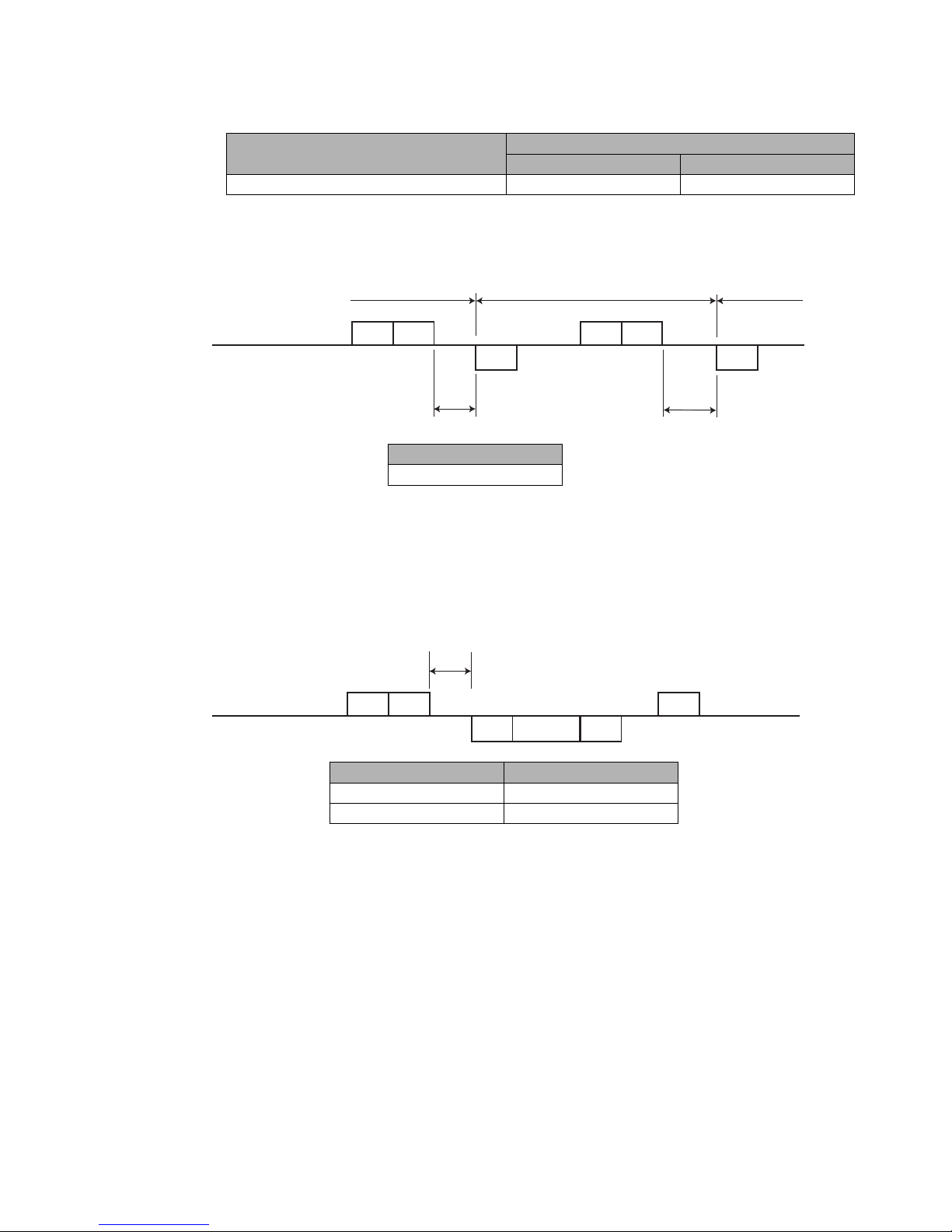
5-49 ●Communication Timing
Externaldevice
ESC2 73H ESC2 74H
ACK
ACK
T
T
On-line Off-lineOff-line
IJprinter
Externaldevice
IJprinter
ESC2 75H ACK
STX
Text ETX
T
(3) On-line/Off-line Transmission
T Maximum time (ms)
50
(4) Current time output Transmission
Baud rate (bps) T Maximum time (ms)
150 to 1200 15
2400 to 115200 5
Time T2 when there is a GS1 DataBar setting
T2 Minimum time (ms)
Within 24 items 25 items or more
GS1 DataBar 10x N+5 10x N+15
(N : Number of GS1 DataBar )
*9 When there is a GS1 DataBar setting, the time is as follows:
Page 96
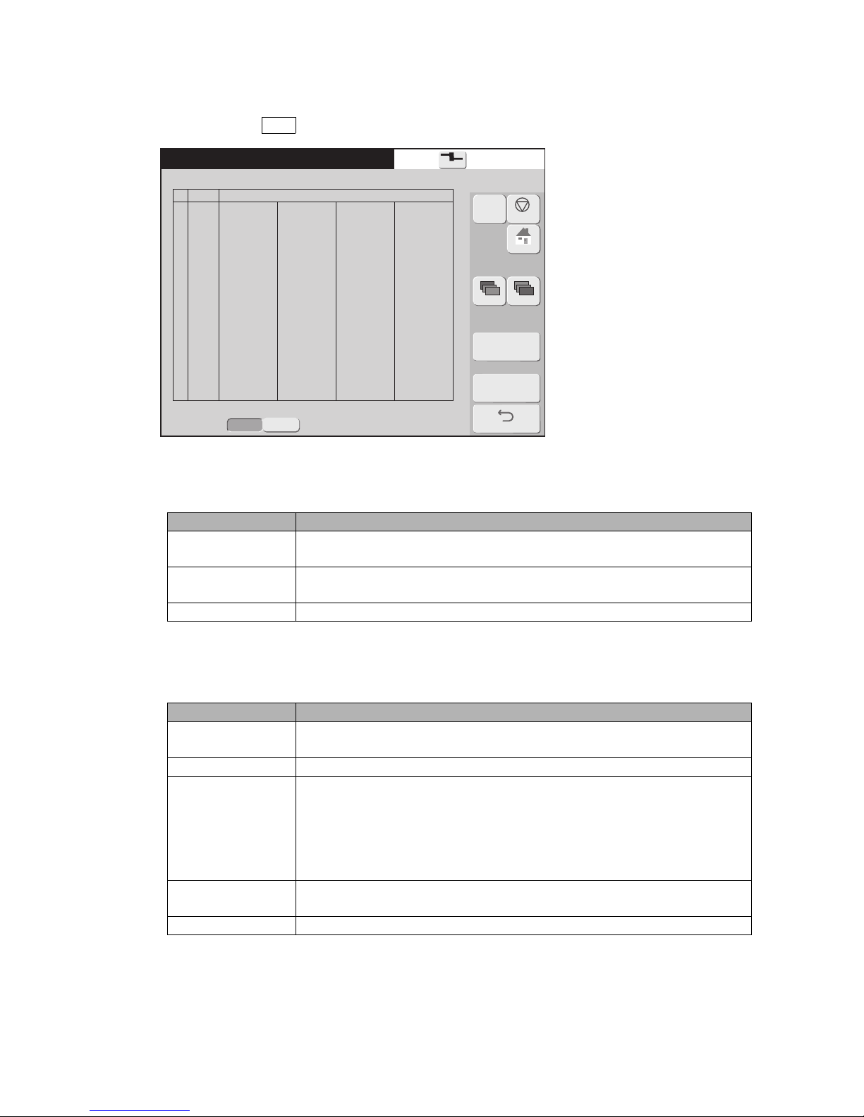
●Communication Monitor Function 5-50
Comm. monitor
2015.07.0712:45
[Ready ]
No
1
2
3
4
5
6
7
8
R
S
R
S
R
S
R
S
05
06
02 10 31 41 42 43 44 45 10 32 31 32 33 34 35 03
06
05
06
02 10 31 41 42 43 44 45 10 32 31 32 33 34 7F 03
15
Communication descriptionTrans.
Back
Prev.Dsp.
NextDsp.
Blue : DLE2,ESC2,DLE,ESC Red : Failed line
Com=1
Start
Abort
Proc. status:HaltedDetection
Disable
Enable
M
Manual
Shutdown
HOME
5.6 Communication Monitor Function
● The contents of serial communications between the external device and IJ printer are displayed.
● Up to 3,000 bytes of data can be acquired at a time.
● When you press the Start button, the system erases monitored data and acquires new data.
(1) Screen display
Item Description
Trans.
External device → IJ printer : R (Receive)
IJ printer → External device : S (Send)
Communication
description
Sended/received data are displayed in hexadecimal notation. Sixteen bytes of
data are displayed per line.
Proc. status The current status is indicated (monitoring or interrupted).
(2) Input keys
Item Description
Start
Starts exercising the line monitor function. Erases the monitored
information.
Abort Aborts the execution of the line monitor function.
Error detection
This switches over whether the system is to detect error-ridden locations.
● Disable: The system will not detect error-ridden locations. The system
will memorize up to bytes 3,000 of data transmitted and received.
● Enable: The system will display error-ridden locations in red. The system
will memorize up to transmitted and received data up to the location where
an error was detected.
Previous list/
Next list
Used to switch to another screen when the amount of information to be
displayed is too large to fit on a single screen.
Back Returns you to the maintenance menu.
Page 97
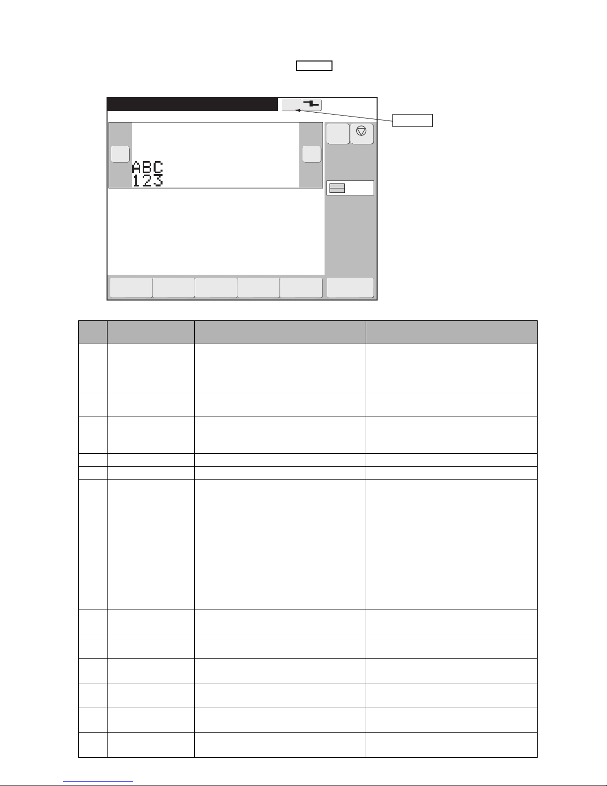
5-51 ●Warning Messages
Print description
2015.07.0712:45
M
Manual
Menu
Com=1
[Ready
]
Ink operating time
100
(hours)
Cumulative op. time
100
(hours)
Print count
1000
(prints)
Ink pressure
0.250
(MPa;standard value:
0.250
)
Message name[
]
− +
Current user ID : user2
Maintenance
Auxiliary
function
Environment
setupmenu
Select
loginuser
Create/Edit
message
Warning
Warning
Interlaced
Shutdown
5.7 Warning Messages
● If any communication is in error, the associated warning message appears below the status display area.
● Note the message to confirm the error and then take remedial action as appropriate for the indicated error
code.
Error code table
Error
code
Name Description Check
001
Transmissioncode
error
● The transmitted code was not defined
for communication use.
● The transmitted message had an illegal
structure.
Check the baud rate and transmission
code.
002
Print specifications
code error
The print specifications data value was
illegal.
Check the print specifications
communication text.
003
Print character code
error
The maximum value was exceeded by
the number of characters for printings
that could be received as one item.
Check the printings communication text.
004 Item number error The item number code value was illegal. Check the printings communication text.
005 Header error The header value was illegal. Check the header.
006
Ready-forreception error
● An attempt was made to establish
communication while the "not ready
for reception" state prevailed.
● "Apply" key and message window
were both displayed.
● "Off-line fixed" has been set in
Communication environment.
● Communication monitor screen was
displayed.
● Communication was conducted during
the stop or shutdown process.
Check the transmission timing.
008
Print specifications
code error
The maximum value was exceeded by
the print specifications data.
Check the print specifications
communication text.
009 ETX code error The ETX code position was illegal.
Check the transmission procedure and
ETX code.
010 DLE code error The DLE code position was illegal.
Check the transmission procedure and
DLE code.
011 STX code error The STX code position was illegal.
Check the transmission procedure and
STX code.
012 ENQ code error The ENQ code position was illegal.
Check the transmission procedure and
ENQ code.
013
ESC code error
(ESC, ESC2)
The ESC code position was illegal.
Check the transmission procedure and
ESC code.
Page 98
●Warning Messages 5-52
Error
code
Name Description Check
014 Parity error The parity error occurred. Check the baud rate and data format.
015
Print format code
error
The print format data value was illegal.
Check the print format transmission text
section.
016 Overrun error The overrun error occurred. Check the baud rate and data format.
017 Framing error The framing error occurred. Check the baud rate and data format.
019 2-byte code error
● An illegal 2-byte code (2 bytes per
character) was transmitted.
● Only one byte of 2-byte code was
transmitted.
Check the 2-byte code transmission text.
020 Print data code error
● The print data registration number was
illegal.
● An unregistered number was
encountered.
Check the print data recall / transmission
code.
021 SI/SO code error
The SI (shift in) or SO (shift out) code
position was illegal.
Check the printings communication text.
022
User pattern
character size/
character code error
The character size or character code
values were illegal.
Check the user pattern communication
text.
023
High-speed
printing setup error
● When necessary conditions for high
speed printing were not satisfied, NM
or QM mode was transmitted.
● When High speed printing NM or QM
mode was set, a setting which did not
satisfy necessary conditions for high
speed printing was transmitted.
Check the print specifications
communication text.
024
Calendar/count
conditions error
● Transmitted to block where
calendar/count characters were not
present.
● Set value was outside specifications.
● Zero suppression transmission was
performed to print item for which
barcode had been set.
Check calendar/count condition
communication text.
026 Bar code setup error
● A character undefined for bar code use
was found in the printings.
● The number for ITF did not consist of
an even number of numerals
beginning with an odd digit position.
● The input data for EAN-13 was not
numeric.
Check the printings print format
communication text.
027 Printings error
● A dedicated character or katakana was
transmitted in a character size which
cannot be inputted.
● The three characters of a dedicated
character string were not properly
grouped.
● A count value is out of a count range.
Check the printings communication text
031
Create messages
error
● While "Create messages" function was
operating, on-line transmission was
performed.
● On-line transmission was performed
when print data which was controlled
separately from data created and
registered by print description screen,
was present.
Check the timing of on-line
transmission.
032
Setting conditions
error
● Setting value does not satisfy the
required conditions.
Communication text re-check.
033 Setting range error ● Setting value is out of stipulated range. Communication text re-check.
Page 99
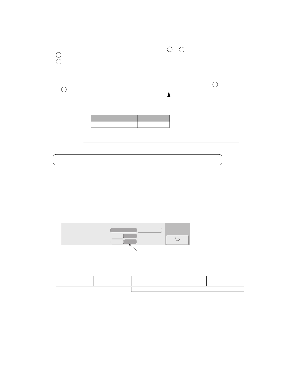
5-53 ●Precautions
Back
<Standard communication>
Communication mode
Print message transfer ACK
Print spec transfer char height
3 digits
2 digits
overwrite-protected
overwrite-enabled
t=async.
t=fixed
5.8 Precautions
5.8.1 Notes on Product speed matching Feature Use
(1) If the product speed matching signal cannot be entered during printing, the printing state
continues to prevail so that communication may not be established (no response can be made).
If such a situation is encountered, perform procedure or below.
Enter the standby state and then initiate the communication.
Issue the print abort code "DC3". After the IJ printer returns an "ACK" response,
(2) Number of pulses necessary for a rotary encoder from print signal detection until the start of
printing.
Number of pulses necessary = Number of printing preparation pulses ( ) + Print start delay.
Number of printing preparation pulses = A / 1 scan time
Use an integer by rounding up the fractional portion.
Nozzle diameter Value of A
65μm5.5
1 scan time =
(Vertical dot count + character width setting) X Ink drop use percentage
Excitation frequency (kHz)
(ms)
5.8.2 Notes on Print Condition Transmission
(1) The number of digits for character height data is 2 by default. However, the preceding IJ printer
models GX and HX use 3 digits by default for print condition transmission (optional function). If the
new model of the IJ printer is used as a replacement for such a predecessor, open the following
screen from the communication environment setup screen and change the number of digits for
character height data to 3.
ESC Header 30H 100s place 10s place Units place
Character height (000 to 099)
● Character height (when the 3-digit data format is chosen)
Note: If the value is within the range from 100 to 999, an error occurs.
1
2
1
2
1
1
Data digts of the character height
When “Speed compensation” is enabled, print start is delayed for 30 scans.
Page 100
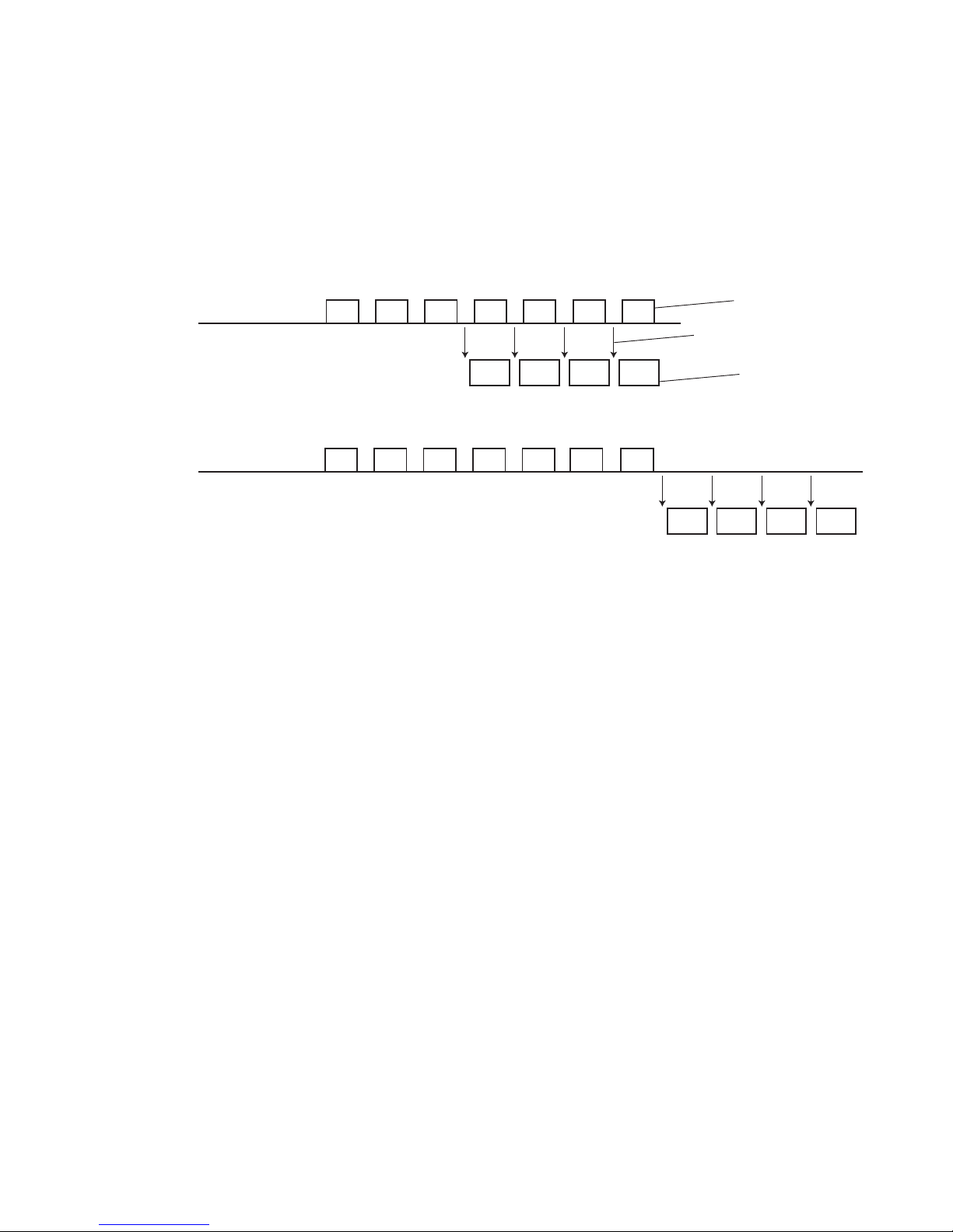
●Communication Buffer 5-54
Externaldevice
IJprinter
A B C D E F G
A
B C D
Printing
Detectionofprint
startsignal
Printcontent
transmission
Printing
Externaldevice
IJprinter
A B C D E F G
A
B C D
Printing
5.9 Communication Buffer
5.9.1 Overview
(1) Print content transmission
● The print contents received through print content transmission will not be reflected in printing
immediately, but will be temporarily held in buffer.
● The print contents are fetched from the buffer one by one for each printing, and reflected in subsequent
printing.
[Example of transmitting print contents constantly during printing]
[Example of transmitting collective print contents at the beginning]
 Loading...