

Hitachi R-W660ERU9-2 Service Manual
TABLE
SPECIFICATION ...............................................................................................
2
MAIN PARTS COMPONENTS ..................................................................................
2
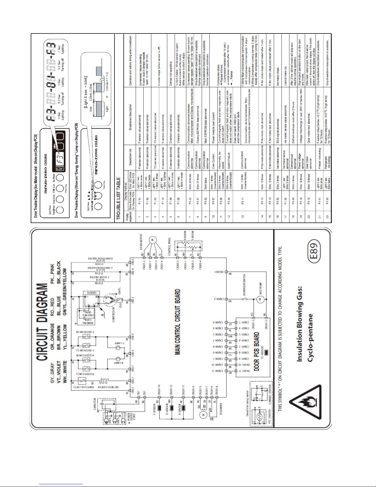
CIRCUIT DIAGRAM ..................................................................................
3
ERROR TROUBLE DISPLAY ...............................................................
3
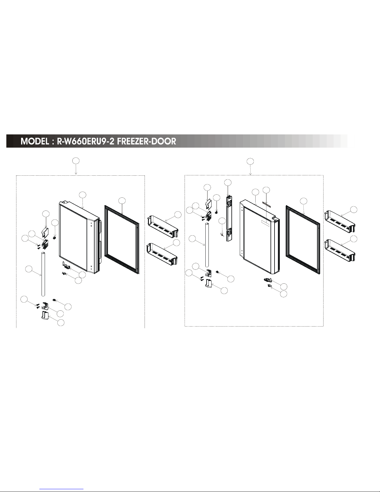
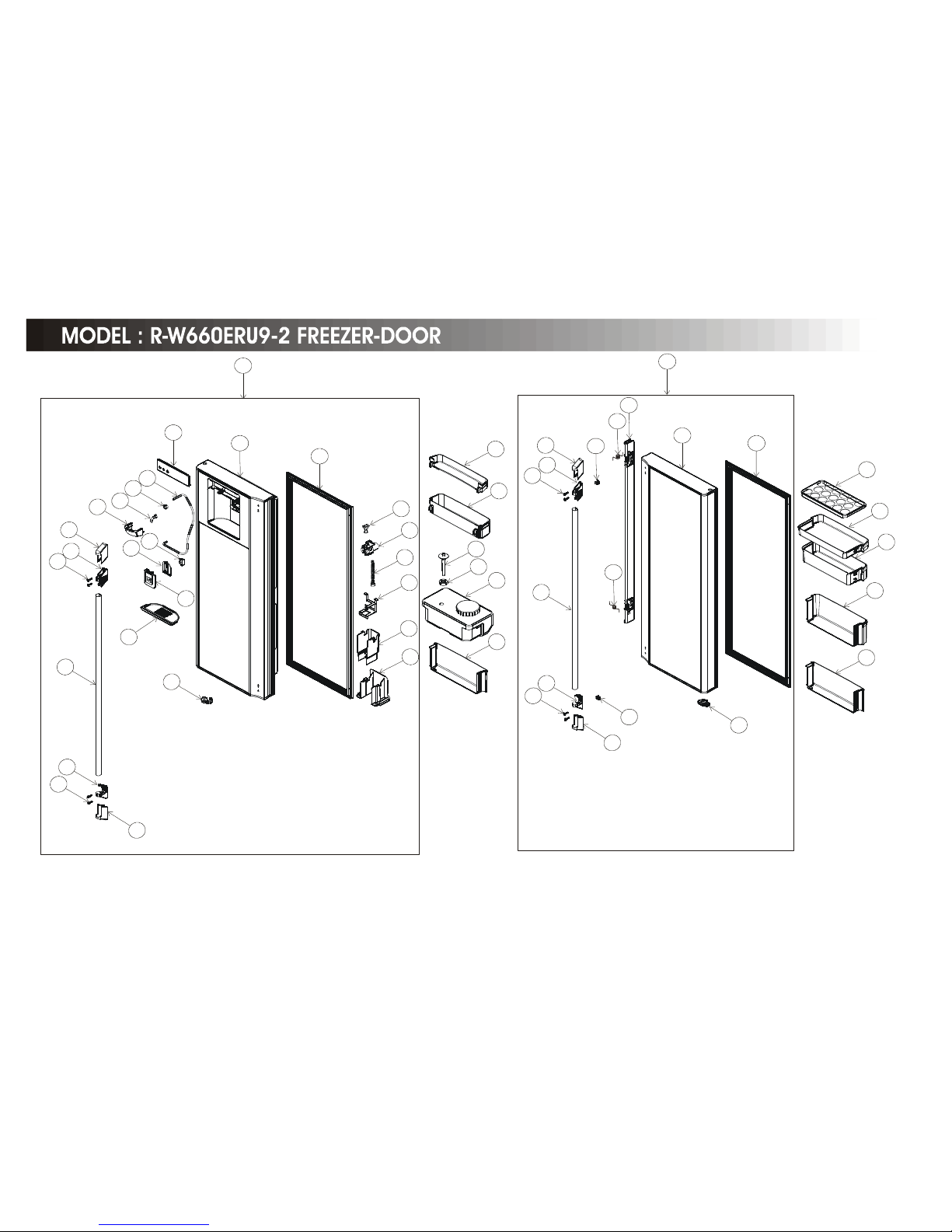
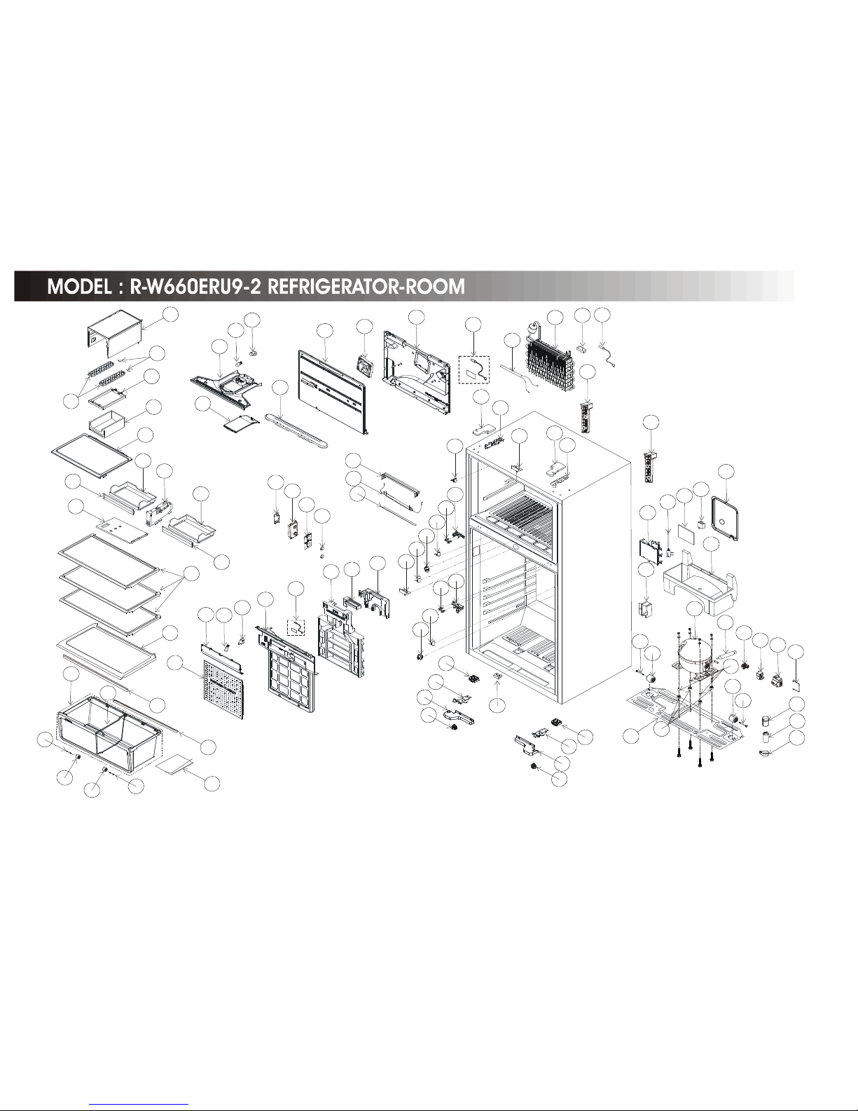
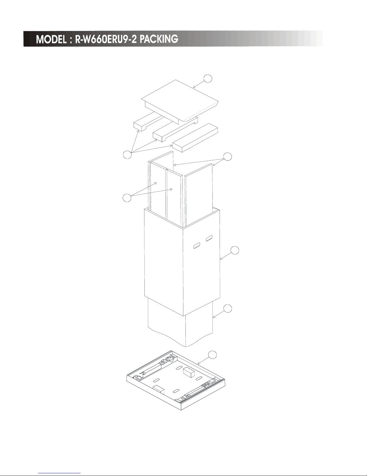
PART CATALOG .............................................................................................
4-7
PARTS LIST
MODEL:R-W660ERU9-2 (GS) ................................
8-12
MODEL:R-W660ERU9-2 (GBK) ................................
13-17
MODEL:R-W660ERU9-2 (STS) ................................
19-22
SPECIFICATIONS
TYPEFRENCH 4DOOR
MODELR-W660ERU9-2
POWER SOURCE 1Ø,220-240V,50Hz
POWER INPUT ( W )240
TOTAL CURRENT ( A )1.6
VOLUMENET550L
W 845
H 1800
D 715
NET WEIGHT ( Kgs )102
REFRIGERATOR
DEC '2011
H.C.P.T.
SERVICE MANUAL
TOTAL
DIMENSIONS
PT
NO. 2437E
R-W660ERU9-2 (GS,GBK,STS)
For servicing details, Please
refer to service guide No. 2392E
1.
For disassembly
and repair the unit
be sure to disconnect the power cord plug
from the power outlet before starting the work.
2.
If it is necessary to replace any parts, they should be replaced with
correct parts for the unit, and the
replacement must be effected in correct manner according to the instructions in the Service Manual of the unit.
3.
After completion of repairs, the initial state should be restored.
4.
Lead wires should be connected and
wiring as in the initial state.
5.
Modification of the unit by the user himself should absolutely be
prohibited.
6.
Tools and measuring instruments for
repair or inspection should be accurately calibrated in advance.
7.
In installing the unit having been repaired, be careful to prevent the occurrence of any accident such as electrical
shock, leak of current, or bodily injury due to the drop of any part.
8.
To check the insulation of the unit, measure the insulation resistance between the power cord plug and grounding
terminal of the unit.
The insulation resistance should be 1M
Ω
or more as measured by a 500V DC.
9.
The initial location of installation such as window, floor or the other should be checked for being safe enough to
support the repaired unit again.
If it is found not so strong and safe, the unit should be installed at the initial location after reinforced or at a new location.
10.
Any inflammable object must not be placed
about the location of installation.
11.
Check the grounding to see whether it is proper
or not, and if it is found improper, connect the
grounding terminal to the earth.
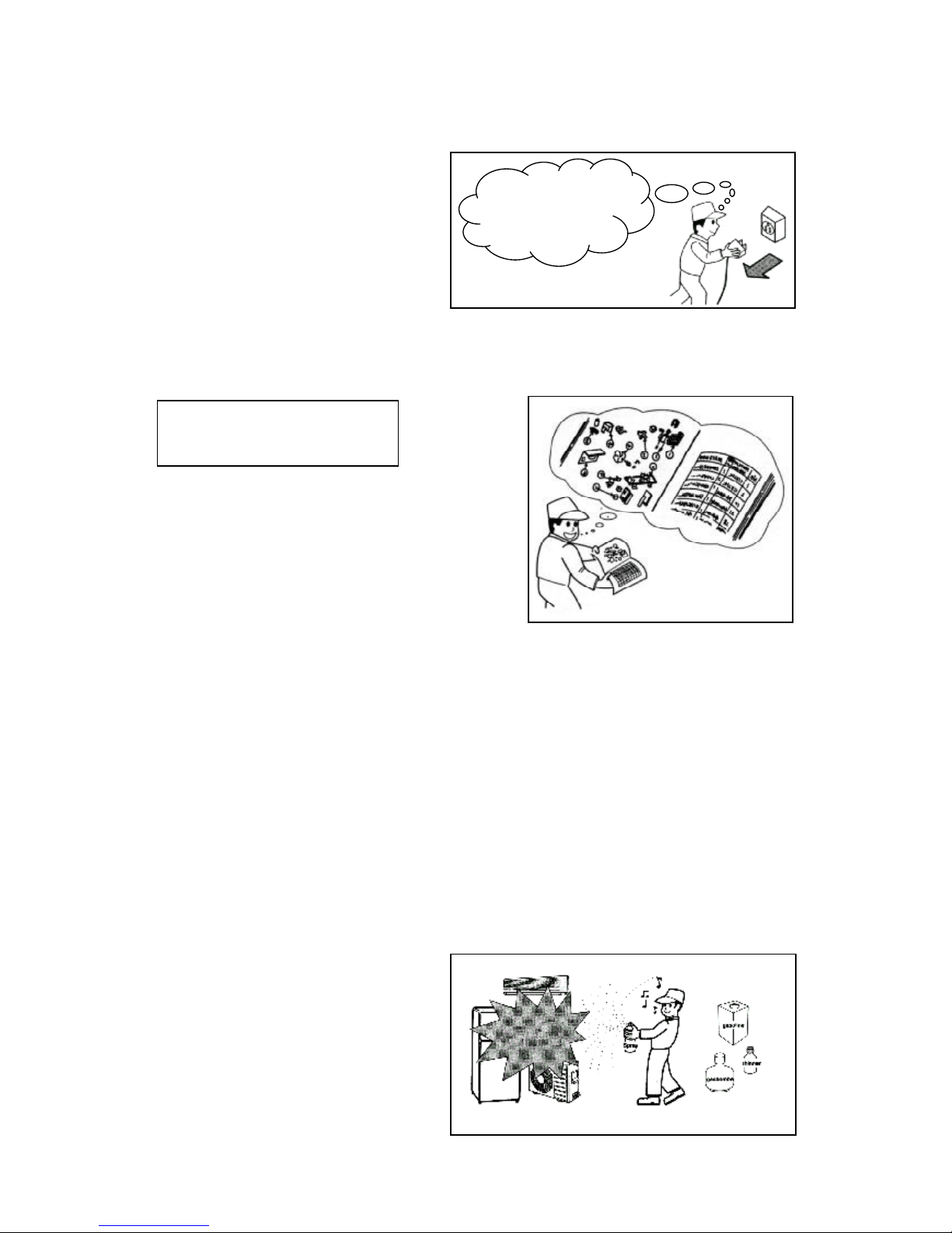
SAFETY DURING REPAIR WORK
First, I must disconnect
the power cord plug
from the power outlet.
If electrical parts are defective,
replace the electrical parts
without trying to repair them.
DANGER
1
MODELR-W660ERU9-2
COMPRESSORPTR-W720EM 016 (C-BF200L5Z)
STARTING DEVICEPTR-W720EM 018 (PTH7M330MB3)
OVERLOAD RELAYPTR-W720EM 017 (OLR 4TM293R)
STARTING CAPACITOR
RUNNING CAPACITOR
REFRIGERATOR SENSORPTR-W720FMX 071 R(0°C) = 6.35kΩ ±2%
FREEZER SENSORPTR-W720FMX 065 R(-20°C) = 18.9kΩ ±2%
REFRIGERATOR CHARGING 165gr
TEMPERATURE FRESH FOODELECTRONIC CONTROL
CONTROL FREEZERELECTRONIC CONTROL
DEFROSTING WAYHEATER
DEFROSTING INITIATIONF:AUTOMATIC,R:AUTOMATIC
SYSTEM TERMINATIONF:AUTOMATIC,R:AUTOMATIC
EVAPORATIONFORCED
TABLE TOPNO
CRISPER (VEGETABLE)SLIDE OUT
FREEZER * * * *YES
ICE CUBE BOXYES
SHELF-F1 (GLASS-SHELF)
MEAT KEEPER DOORYES
MULTI CHILLERYES
SHELF-R4 (GLASS-SHELF)
ICE TRAYYES
EGG STORAGE CAPACITY17
POCKETYES
POLYURETHANE INSULATORYES
OTHER FEATURE
WATER DISPENSORYES
DEODORIZERNANO TITANIUM
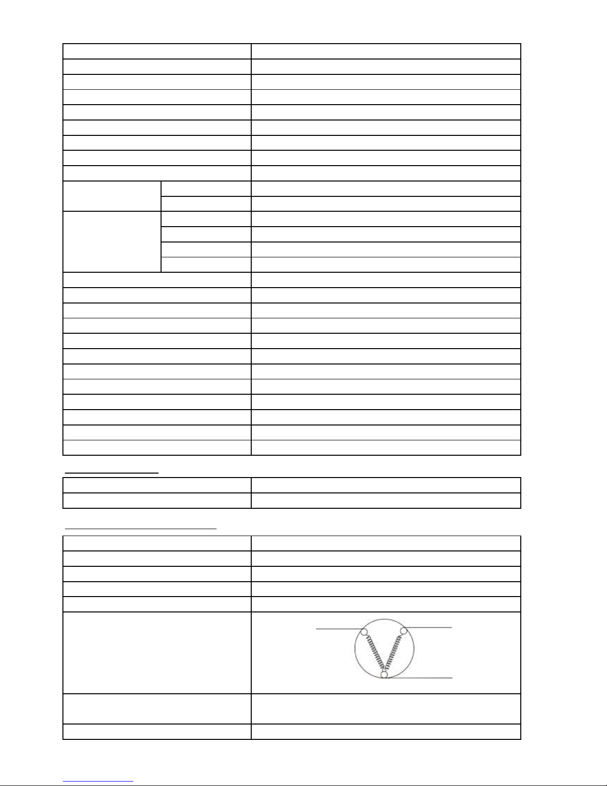
MAIN PARTS COMPONENTS
COMPRESSORPTR-W720EM 016 (C-BF200L5Z)
PHASESINGLE PHASE
RATE VOLTAGE ( V )220-240
RATE FREQUENCY ( Hz )50
POLE NUMBER2
CONNECTION
M - C = 12.54 Ω
S - C = 39.58 Ω
STARTING CURRENT (A)
RESISTANCE VALUE 25°C
8.5
PTR-W70FGD9 003 (40μF)
PTR-Z610EL9 008 (6μF)
MAIN COILSTARTING COIL
MS
C
MAIN COILSTARTING COIL
MS
C
MAIN COILSTARTING COIL
MS
C
MAIN COILSTARTING COIL
MS
C
MAIN COILSTARTING COIL
MS
C
MAIN COILSTARTING COIL
MS
C
2
3
4
1
2
11
3
10
7
9
6
8
12
13
11
14
15
16
17
18
19
20
21
3
14
9
10
6
5
4
7
4
5
6
8
14
14
6
5
22
23
24
25
26
27
30
32
37
38
39
40
41
42
43
44
45
46
47
48
4950245152
11
10
9
6
36
7
4
5
53619
35
10
28
29
31
4
5
6
33
36
9
6
5455565748
6
11011111311511613
6
135
1411391371143011210510710810910
6
93
94
95
961361381411406630303012114915015112011911811712413313313112712912813012613413213212512
2
58
59
78
80
79
77
81
83
82
86
87
88
85
84
61
62
63
65
64
65
66
92
103
102
101
100
99
78
98
97
104
76
68
69
71
123
60
64
67
89
90
91
73
7
2
70
75
74
74
75
142
1
4
3
1
4
4
14514814614
7
7
 Loading...