

Hitachi R-W660ERU9 Service Manual
TABLE
SPECIFICATION ...............................................................................................
2
MAIN PARTS COMPONENTS ..................................................................................
2
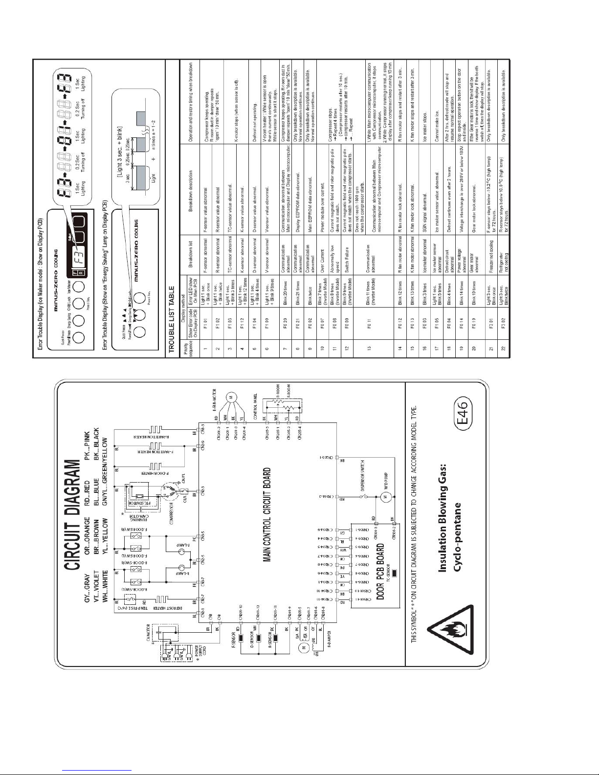
CIRCUIT DIAGRAM ..................................................................................
3
ERROR TROUBLE DISPLAY ...............................................................
3
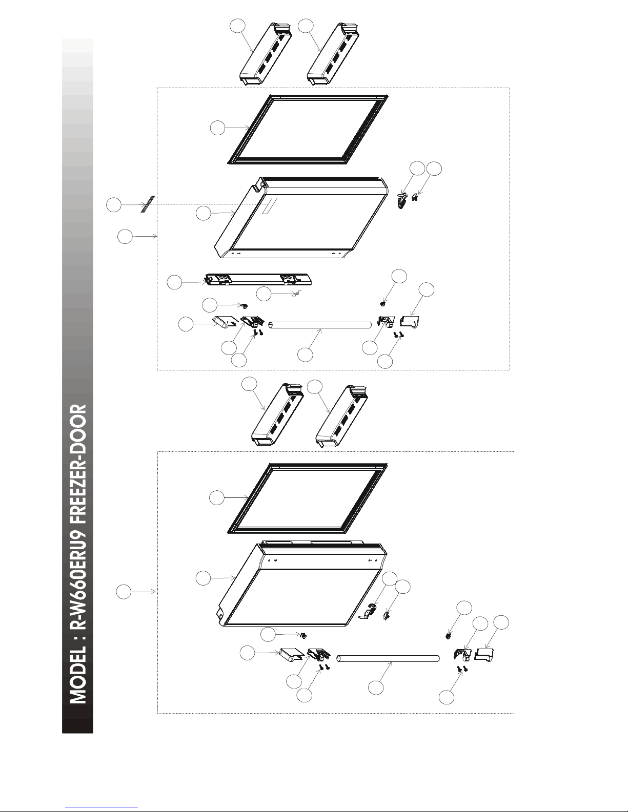
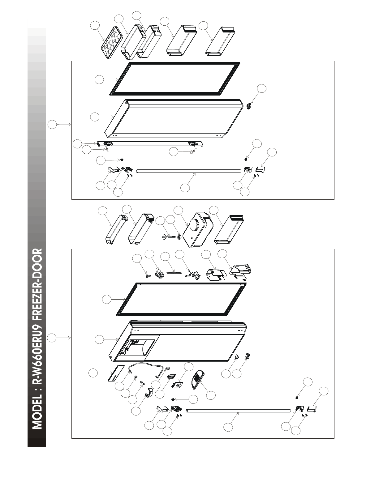
PART CATALOG .............................................................................................
4-7
PARTS LIST
MODEL:R-W660ERU9 (GS) ................................................................
8-12
MODEL:R-W660ERU9 (GBK) ................................................................
13-17
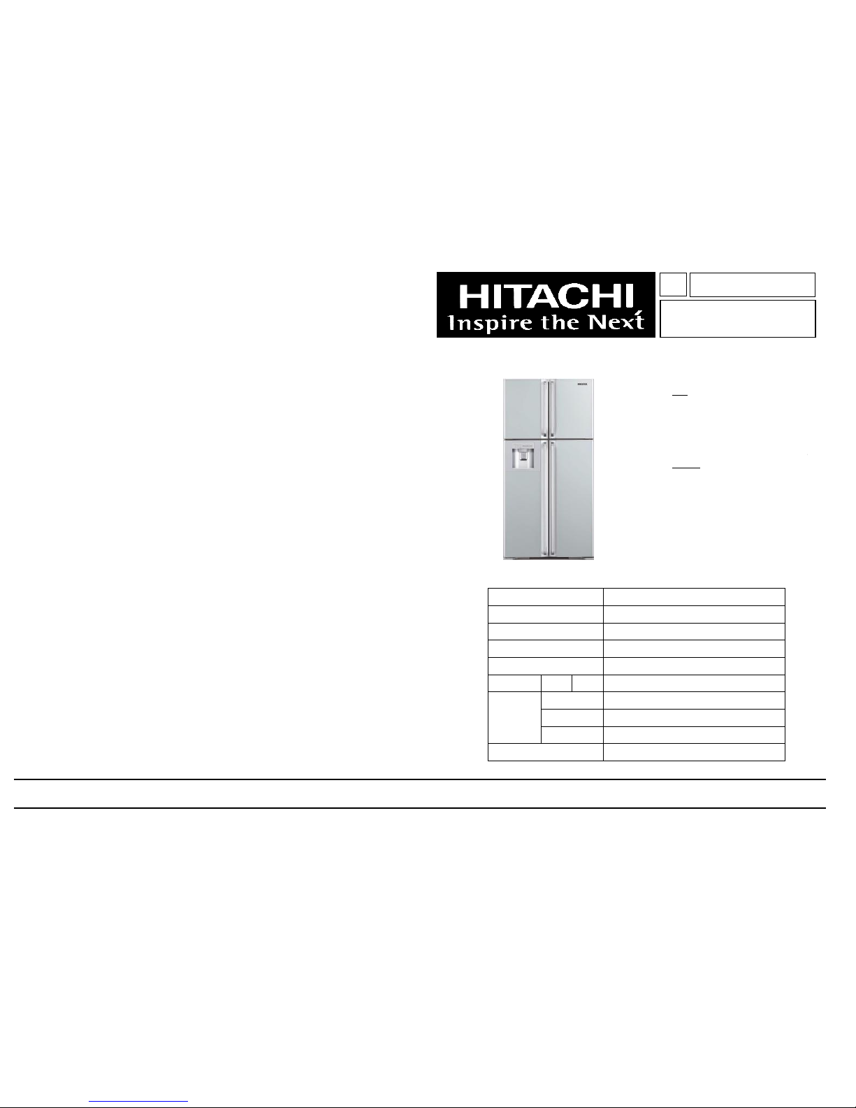
SPECIFICATIONS
TYPEFRENCH 4DOOR
MODELR-W660ERU9
POWER SOURCE 1Ø,220-240V,50Hz
POWER INPUT ( W )240
TOTAL CURRENT ( A )1.6
VOLUMENET550L
W 845
H 1800
D 750
NET WEIGHT ( Kgs )102
R-W660ERU9 (GS,GBK)
REFRIGERATOR
FEB '10
H.C.P.T.
SERVICE MANUAL
TOTAL
DIMENSIONS
NO.1840E
PT
NO
.
1840
E
R-W660ERU9 (GS,GBK)
HITACHI
1.
In order to disassemble and repair the
unit in question, be sure to disconnect
the power cord plug from the power
outlet before starting the work.
2.
If it is necessary to replace any parts, they should be replaced with respective genuine parts for the unit, and the
replacement must be effected in correct manner according to the instructions in the Service Manual of the unit.
3.
After completion of repairs, the initial state should be restored.
4.
Lead wires should be connected and laid as in the initial state.
5.
Modification of the unit by the user himself should absolutely be
prohibited.
6.
Tools and measuring instruments for use in repairs or inspection should be accurately calibrated in advance.
7.
In installing the unit having been repaired, be careful to prevent the occurrence of any accident such as electrical
shock, leak of current, or bodily injury due to the drop of any part.
8.
To check the insulation of the unit, measure the insulation resistance between the power cord plug and grounding
terminal of the unit.
The insulation resistance should be
1
MΩ or more as measured by a
500
V DC megger
.9.The initial location of installation such as window, floor or the other should be checked for being safe enough to
support the repaired unit again.
If it is found not so strong and safe, the unit should be installed at the initial location after reinforced or at a new location.
10.
Any inflammable object must not be placed
about the location of installation.
11.
Check the grounding to see whether it is proper
or not, and if it is found improper, connect the
grounding terminal to the earth.
SAFETY DURING REPAIR WORK
First, I must disconnect
from the power outlet.
If the contacts of electrical parts are
defective, replace the electrical parts
without trying to repair them.
DANGER
the power cord plug
1
MODELR-W660ERU9
COMPRESSORPTR-W660ERU9 A82 (FL20S88NAH)
STARTING DEVICEPTR-470ARU5 (PGTOSAT)
OVERLOAD RELAYPTR-S700ERU8 A128 (2.5C36A1)
STARTING CAPACITOR
REFRIGERATOR SENSORPTR-W660ERU9 A67 R(0°C) = 6.35k ±2%
REFRIGERATOR CHARGING 0.145Kg
TEMPERATURE FRESH FOODELECTRONIC CONTROL
CONTROL FREEZERELECTRONIC CONTROL
DEFROSTING WAYHEATER
DEFROSTING INITIATIONF:AUTOMATIC,R:AUTOMATIC
SYSTEM TERMINATIONF:AUTOMATIC,R:AUTOMATIC
EVAPORATIONFORCED
TABLE TOPNO
CRISPER (VEGETABLE)SLIDE OUT
FREEZER SENSORPTR-W660ERU9 A61 R(-20°C) = 18.9k ±2%
MEAT KEEPER DOORYES
MULTI CHILLERYES
SHELF-R4 (GLASS-SHELF)
ICE TRAYYES
EGG STORAGE CAPACITY17
POCKETYES
POLYURETHANE INSULATORYES
OTHER FEATURE
WATER DISPENSORYES
FREEZER * * * *YES
ICE CUBE BOXYES
SHELF-F1 (GLASS-SHELF)
DEODORIZERNANO TITANIUM
VERTICAL ALUMINIUM HANDLE (FIXED)
YES (4 F)
MAIN PARTS COMPONENTS
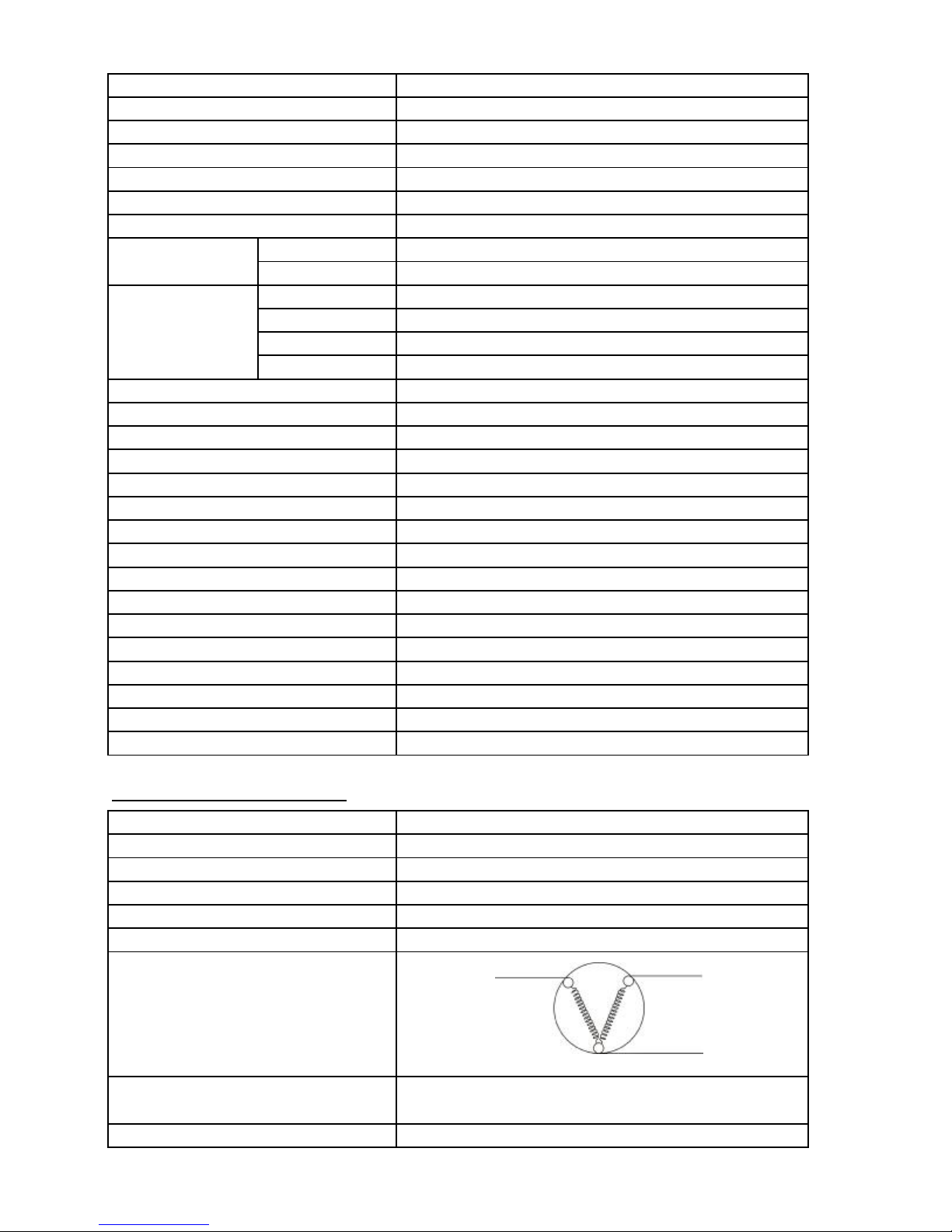
MODELR-W660ERU9
COMPRESSORPTR-W660ERU9 A82 (FL20S88NAH)
PHASESINGLE PHASE
RATE VOLTAGE ( V )220-240V
RATE FREQUENCY ( Hz )50Hz
POLE NUMBER2
CONNECTION
RESISTANCE VALUE 75°C
LOCK ROTOR CURRENT (A)
MS
MAIN COILSTARTING COIL
C
M - C = 8.5 Ω
S - C = 16.9 Ω
12.5 A
2
3
141
4
3
20
21
16
17
15
7
18
19
4
11
10
9
6
14
8
14
5
6
3
2
1
12
13
11
9
10
7
4
5
6
8
6
4
495024545556574851521
1
9
7
455
361
9
10
6
36
43
44
38
37
47
46
45
40
39
48
42
41
24
22
23
32
25
26
27
28
30
31
33
7
35
34
11
10
29
5
4
6
36
9
6
5
 Loading...