

Page 1
TABLE
SPECIFICATION ............................................................................................
2
MAIN PARTS COMPONENTS ..................................................................................
2
BASIC OPERATION..................................................................................
3
RESISTANCE VALUE ..................................................................................
4
ERROR CODE ..................................................................................
5
CIRCUIT DIAGRAM ..............................................................................
6
PARTS CONSTITUTION
MODEL:R-T310ERU1 .............................................................................................
7-18
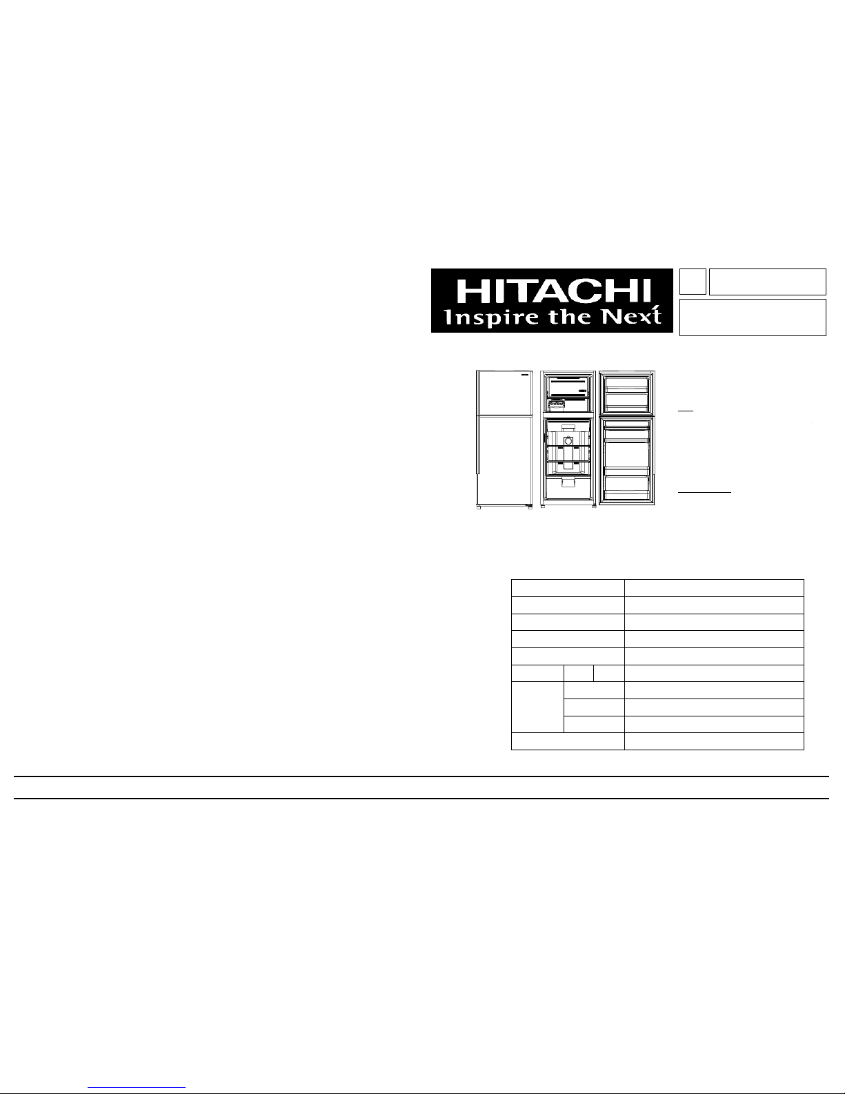
SPECIFICATIONS
TYPEDOUBLE DOOR
MODEL
POWER SOURCE 1Ø,220V-240V,50Hz
POWER INPUT ( W )120
TOTAL CURRENT ( A )0.9
VOLUME260L
600
1560
655
NET WEIGHT ( Kgs )54
NO. 2022E
REFRIGERATOR
H.C.P.T.
OCT'2010
R-T310ERU1 (SLS,PWH,PBK)
R-T310ERU1
SERVICE MANUAL
DIMENSIONS
(mm)
TOTALNET
W
H
D
HITACHI
PT
NO. 2022E
R-T310ERU1 (SLS,PWH,PBK)
GENERAL SERVICE
Page 2
1.
In order to disassemble and repair the
unit in question, be sure to disconnect
the power cord plug from the power
outlet before starting the work.
2.
If it is necessary to replace any parts, they should be replaced with respective genuine parts for the unit, and the
replacement must be effected in correct manner according to the instructions in the Service Manual of the unit.
3.
After completion of repairs, the initial state should be restored.
4.
Lead wires should be connected and laid as in the initial state.
5.
Modification of the unit by the user himself should absolutely be
prohibited.
6.
Tools and measuring instruments for use in repairs or inspection should be accurately calibrated in advance.
7.
In installing the unit having been repaired, be careful to prevent the occurrence of any accident such as electrical
shock, leak of current, or bodily injury due to the drop of any part.
8.
To check the insulation of the unit, measure the insulation resistance between the power cord plug and grounding
terminal of the unit.
The insulation resistance should be 1M
or more as measured by a 500V DC megger.
9.
The initial location of installation such as window, floor or the other should be checked for being safe enough to
support the repaired unit again.
If it is found not so strong and safe, the unit should be installed at the initial location after reinforced or at a new location.
10.
Any inflammable object must not be placed
about the location of installation.
11.
Check the grounding to see whether it is proper
or not, and if it is found improper, connect the
grounding terminal to the earth.
SAFETY DURING REPAIR WORK
First, I must disconnect
from the power outlet.
If the contacts of electrical parts are
defective, replace the electrical parts
without trying to repair them.
DANGER
the power cord plug
Ω
1
Page 3
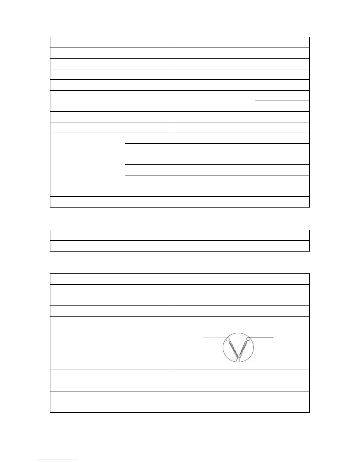
SPECIFICATION
MODEL
COMPRESSORPTR-T310EM 001(FL1152-SH)
STARTING DEVICEPTR-250EX 021(PGT0SAT)
OVERLOAD RELAYPTR-200WGX 037(1.4C36A3)
STARTING CAPACITORPTR-47KP 003(3μF/400V)
AMBIENT TEMPERATURE SENSOR
REFRIGERATOR SENSORPTR-T300W 034R (O°C) = 6.35 k Ω ± 2 %
REFRIGERATOR CHARGING R-134a (kg)
TEMPERATURE FRESH FOOD
CONTROL FREEZER
DEFROSTING WAY
DEFROSTING INITIATION
SYSTEM TERMINATION
EVAPORATION
FREEZER ****
PTR-Z400V 050
R-T310ERU1
R (21°C) = 12 k Ω ± 3 %
R (25°C) = 10 k Ω ± 2 %
0.095
DIAL
SELECT DAMPER DIAL
HEATER
F:AUTOMATIC,R:AUTOMATIC
F:AUTOMATIC,R:AUTOMATIC
FORCED
YES
OTHER FEATURE
MINUS-ZERO COOLING
NANOTITANIUM
NO
YES
MAIN PARTS COMPONENTS
COMPRESSORPTR-T310EM 001(FL1152-SH)
PHASESINGLE PHASE
RATE VOLTAGE ( V )220
RATE FREQUENCY ( Hz )50
POLE NUMBER2
MS
CONNECTION
RESISTANCE VALUE 75°C
MAIN COILSTARTING COIL
C
M - C = 23.8 Ω
S - C = 42.4 Ω
STARTING CURRENT (A)
DEFROST HEATER
6.0
230V/165W/322.7 Ω
2
Page 4
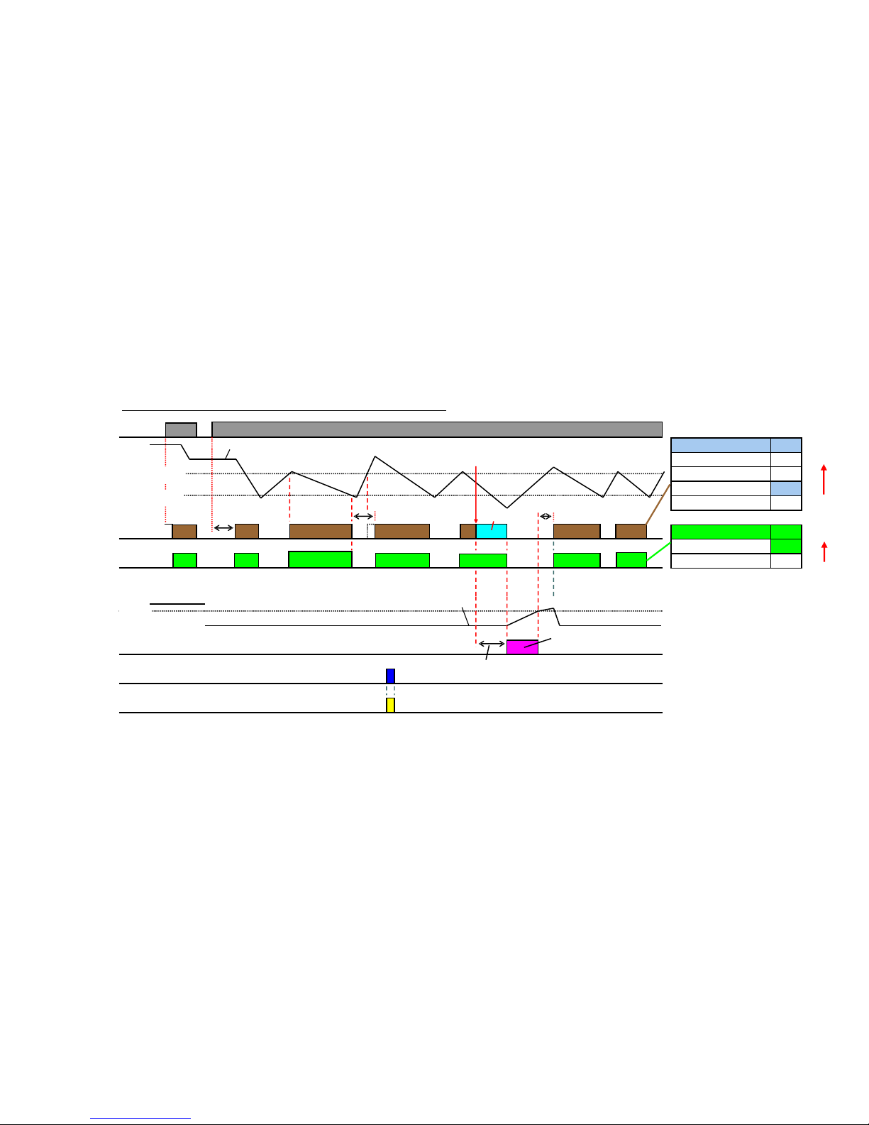
Off-time
Defrosting
R-sensor≧High temp.
R-sensor≦Low temp.
Comp. on
Comp. off
Off
3
Comp.Condition
Off
Off
On
Off
ConditionR-Fan
On
●Comp.
●Power
supply
●R-Room
Temp.
●R-Fan
●Evaporator
Temp.
●Defrost
heater
●R-Lamp
High temp.(4℃)
Low temp.(2℃)
On
R-sensor
On
Open
On
●R-Door
(R-Door sw)
8.5℃
D-sensor
On
On
~~~~~~~~
Off-time
10min
~
t1t2t3t4
Pre-Cool
Off-time
10min
Pre-Cool time≦30min
Basic operation(time chart) of 260-290L (STD) REF.
Comp. On-time:
t1+t2+t3+t4+…≧12h
High
Priority
Off-time
10min
High
Priority
Defrosting
25 s
Page 5
RESISTANCE VALUE RESISTANCE
Temp.ResistanceTemp.ResistanceTemp.Resistance
(℃)(Ω)(℃)(Ω)(℃)(Ω)
~~~~~~
-2019.23k-58271.14k-20105.38k
~~~~~~
-1514.26k-2019.17k-1582.03k
-1010.78k-1010.83k-1060.86k
-58.23k-58.27k-545.67k
06.35k06.38k034.62k
54.94k54.97k526.52k
103.88k103.90k1020.50k
153.08k153.09k1515.99k
202.46k202.47k2012.00k
251.98k251.98k259.97k
301.60k301.61k307.97k
351.31k401.08k356.42k
401.07k500.74k405.20k
~~~~~~
600.51k610.50k622.32k
~~~~~~
R-sensorD-sensorTC-sensor
4
Normal
range
Abnormal
range
Abnormal
range
Display
Error code
Display
Error code
Page 6

ERROR CODE
Priority
sequence
Error code
(LED on PCB)
Breakdown
list
Breakdown
description
Operation
11s ON + Blink twiceR-sensor abnormalR-sensor value abnormalProvisional mode
21s ON + Blink 3 timesTC-sensor abnormalTC-sensor value abnormalDisplay error code
31s ON + Blink 4 timesD-sensor abnormalD-sensor value abnormalNo defrosting
4Blink twice
EEPROM data
abnormal
EEPROM data
abnormal
Display error code
5Blink 4 times
Defrosting circuit
abnormal
Defrosting continues
even after 2 hours
After 2 hours,stop defrosting
and display error code
63s ON + Blink twiceRefrigerator not cool
R-sensor stays over 10℃
for 72 hours
Display error code
5
Page 7

MODEL : R-T310ERU1 (SLS,PWH,PBK)
6
Page 8

6
2
3
4
5
8
7
9
10
10
11
12
12
13
13
1
Page 9

14
23
26
27
15
16
70
69
72
71
74
79
76
75
78
77
88
73
10
10
16
85
28
17
21
22
19
52
86
87
50
51
49
48
46
47
38
29
31
32
33
34
35
36
37
55
61
53
54
62
57
56
56
58
59
63
60
68
67
66
65
64
39
30
40
41
42
43
44
45
18
20
24
25
84
83
82
81
80
Page 10

92
89
90
91
93
94
95
Page 11

MODEL: R-T310ERU1 (SLS)
Q'TY/SET
R-T310ERU1
1PTR-Z307AM 001DOOR-BADGE1
2PTR-T300W 001DOOR-PANEL-F-ASS'Y (SLS)1**
3PTR-T270W 013DOOR-GASKET-F1**
4PTR-T300W 004DOOR-PANEL-F (SLS)1**
5PTR-25A3P 021DOOR STOPPER (PMG,PGR,STL,SLS)1
6PTR-T270W 001DOOR-PANEL-R-ASS'Y (SLS)1**
7PTR-T270W 003DOOR-GASKET-R1**
8PTR-T270W 004DOOR-PANEL-R (SLS)1**
9PTR-200WKX 060DOOR STOPPER1
10PTR-T300W 011DOOR-RACK-F2
11PTR-44A4P 003E-CASE-4751
12PTR-T300W 012DOOR-RACK-R12
13PTR-T300W 013DOOR-RACK-R22
14PTR-T300W 014PLA-SHELF-F1
15PTR-T300W 015CHILLER1
REMARKSNO.SERVICE NO.SERVICE NAME
16PTR-T300W 016GLASS-SHELF-R2
17PTR-T300W 017GLASS-SHELF-CRISPER-ASS'Y1
18PTR-T300W 018GLASS-SHELF CRISPER1
19PTR-T300W 019FRAME-BUTTON1
20PTR-T300W 020V-SHUTTER1
21PTR-T300W 021CRISPER1
22PTR-T310ERU 001INSTRUCTION-BOOK1
23PTR-T300W 023ICE-CORNER1
24PTR-610AS3T 021ICE-MAKER-SPRING2
25PTR-200WKX 013ICE TRAY2
26PTR-T300W 024ICE-MAKER-SUPPORT1
27PTR-190NX 006ICE-BANK-04 TB1
28PTR-T300W 025F-GRILL1
29PTR-T300W 026FAN-GUARD-ASS'Y1
30PTR-Z380RX 046DIAL-F1
31PTR-T300W 027MOUTH-PLATE1
32PTR-923V 050BANE MOTOR1
33PTR-Z400R 004FAN1
** : RELATED PART FOR COOLING SYSTEM
10
Page 12

MODEL: R-T310ERU1 (SLS)
Q'TY/SET
R-T310ERU1
34PTR-200WGX 015MOTOR BUSH1
35PTR-Z580AM 013MOTOR-R1**
36PTR-12A9HD 029RUBBER-R1
37PTR-190N 032RM-FIXER1
38PTR-Z470EG9 008PCB-PANEL-395L-STD1**
39PTR-Z470EG9 009C-PANEL-STD1
40PTR-Z470EG9 010STICKER-CP-STD-NW-091
41PTR-Z400V 046TEMP-CTL-DIAL1
42PTR-578AM 048SCREW-COVER (SLS,TIS)1
43PTR-T270W 014CENTER-HINGE-SHEET1
44PTR-208A1HE 025CENTER HINGE-NF-011
45PTR-25A3P 022DOOR SWITCH1**
46PTR-600ET3X 016LAMP1
47PTR-T270W 006R-PANEL-ASS'Y1
48PTR-T270W 007R-DUCT1
REMARKSNO.SERVICE NO.SERVICE NAME
49PTR-T270W 008R-PANEL1
50PTR-T300W 034R-SENSOR1**
51PTR-T300W 035R-PANEL-SENSOR-COVER1
52PTR-T300W 036LAMP-COVER1
53PTR-T300W 037HEATER-COVER-31
54PTR-T300W 038HEATER-220V1**
55PTR-T300W 039HEATER-COVER-21
56PTR-T300W 061EVAP-SUPPORT2
57PTR-T300W 040EVAPORATOR1**
58PTR-208A1HE 010SENSOR HOLDER1
59PTR-Z400V 030D-SENSOR1**
60PTR-T300W 062FUSE1**
61PTR-T300W 041UP-HINGE-COVER1
62PTR-T300W 063UP-HINGE1
63PTR-T310EG1 002POWER CORD1**
64PTR-SBS6200T 027HOLE-CAP1
65PTR-T300W 044PCB-COVER1
66PTR-T300W 045PCB-290L-10-STD1**
** : RELATED PART FOR COOLING SYSTEM
11
Page 13

MODEL: R-T310ERU1 (SLS)
Q'TY/SET
REMARKSNO.SERVICE NO.SERVICE NAME
R-T310ERU1
67PTR-T300W 046PCB-CASE1
68PTR-Z400V 050TC-SENSOR1**
69PTR-47KP 003CAPA-47KP1**
70PTR-T300W 047DRAIN-PAN1
71PTR-Z610EG9 002CORD-CASE1
72PTR-14MX7 008DRYER KMP (NON-CFC)1**
73PTR-S700EUK8 132DRYER-FIXER1
74PTR-200WGX 037OVERLOAD RELAY1**
75PTR-S37NVH 018CORD-COMP1
76PTR-250EX 021STARTING DEVICE1**
77PTR-13EP 034TERMINAL-COVER1
78PTR-923V 068COMP COVER LOCK1
79PTR-T310EM 001COMPRESSOR1**
80PTR-SF37WVPH 108HEX NUT M63
81PTR-Z470AUK6K 018WASHER3
82PTR-T270W 009PIPE3
83PTR-N39WS 061HEX-BOLT (UP HING)3
84PTR-T270W 010R-GROMMET4
85PTR-T300W 049COMPRESSOR-BASE1
86PTR-T300W 050LO-HINGE1
87PTR-400WP 039ADJUSTER-R1
88PTR-400WP 038ADJUSTER-L1
89PTR-T300W 055UP-CARTON1
90PTR-T300W 056UP-CUSHION1
91PTR-570EN4 006SIDE CUSHION1
92PTR-T300W 057FRONT-CUSHION1
93PTR-T310ERU 002CARTON-BOX-R-T310ERU1 (SLS)1
94PTR-Z410AM-1 007POLY-BAG '081
95PTR-T300W 060CARTON-BASE1
** : RELATED PART FOR COOLING SYSTEM
12
Page 14

MODEL: R-T310ERU1 (PWH)
Q'TY/SET
R-T310ERU1
1PTR-Z307AM 001DOOR-BADGE1
2PTR-T310E1H 001DOOR-PANEL-F-ASS'Y (PWH)1**
3PTR-T270W 013DOOR-GASKET-F1**
4PTR-T310E1H 002DOOR-PANEL-F (PWH)1**
5PTR-25A3P 021DOOR STOPPER (PMG,PGR,STL,SLS)1
6PTR-T310E1H 003DOOR-PANEL-R-ASS'Y (PWH)1**
7PTR-T270W 003DOOR-GASKET-R1**
8PTR-T310E1H 004DOOR-PANEL-R (PWH)1**
9PTR-200WKX 060DOOR STOPPER1
10PTR-T300W 011DOOR-RACK-F2
11PTR-44A4P 003E-CASE-4751
12PTR-T300W 012DOOR-RACK-R12
13PTR-T300W 013DOOR-RACK-R22
14PTR-T300W 014PLA-SHELF-F1
15PTR-T300W 015CHILLER1
REMARKSNO.SERVICE NO.SERVICE NAME
16PTR-T300W 016GLASS-SHELF-R2
17PTR-T300W 017GLASS-SHELF-CRISPER-ASS'Y1
18PTR-T300W 018GLASS-SHELF CRISPER1
19PTR-T300W 019FRAME-BUTTON1
20PTR-T300W 020V-SHUTTER1
21PTR-T300W 021CRISPER1
22PTR-T310ERU 001INSTRUCTION-BOOK1
23PTR-T300W 023ICE-CORNER1
24PTR-610AS3T 021ICE-MAKER-SPRING2
25PTR-200WKX 013ICE TRAY2
26PTR-T300W 024ICE-MAKER-SUPPORT1
27PTR-190NX 006ICE-BANK-04 TB1
28PTR-T300W 025F-GRILL1
29PTR-T300W 026FAN-GUARD-ASS'Y1
30PTR-Z380RX 046DIAL-F1
31PTR-T300W 027MOUTH-PLATE1
32PTR-923V 050BANE MOTOR1
33PTR-Z400R 004FAN1
** : RELATED PART FOR COOLING SYSTEM
13
Page 15

MODEL: R-T310ERU1 (PWH)
Q'TY/SET
R-T310ERU1
34PTR-200WGX 015MOTOR BUSH1
35PTR-Z580AM 013MOTOR-R1**
36PTR-12A9HD 029RUBBER-R1
37PTR-190N 032RM-FIXER1
38PTR-Z470EG9 008PCB-PANEL-395L-STD1**
39PTR-Z470EG9 009C-PANEL-STD1
40PTR-Z470EG9 010STICKER-CP-STD-NW-091
41PTR-Z400V 046TEMP-CTL-DIAL1
42PTR-610AS3T 067SCREW-COVER (PWH,SWH,TWH)1
43PTR-T270W 014CENTER-HINGE-SHEET1
44PTR-208A1HE 025CENTER HINGE-NF-011
45PTR-25A3P 022DOOR SWITCH1**
46PTR-600ET3X 016LAMP1
47PTR-T270W 006R-PANEL-ASS'Y1
48PTR-T270W 007R-DUCT1
REMARKSNO.SERVICE NO.SERVICE NAME
49PTR-T270W 008R-PANEL1
50PTR-T300W 034R-SENSOR1**
51PTR-T300W 035R-PANEL-SENSOR-COVER1
52PTR-T300W 036LAMP-COVER1
53PTR-T300W 037HEATER-COVER-31
54PTR-T300W 038HEATER-220V1**
55PTR-T300W 039HEATER-COVER-21
56PTR-T300W 061EVAP-SUPPORT2
57PTR-T300W 040EVAPORATOR1**
58PTR-208A1HE 010SENSOR HOLDER1
59PTR-Z400V 030D-SENSOR1**
60PTR-T300W 062FUSE1**
61PTR-T310E1H 005UP-HINGE-COVER 1
62PTR-T300W 063UP-HINGE1
63PTR-T310EG1 002POWER CORD1**
64PTR-SBS6200T 027HOLE-CAP1
65PTR-T300W 044PCB-COVER1
66PTR-T300W 045PCB-290L-10-STD1**
** : RELATED PART FOR COOLING SYSTEM
14
Page 16

MODEL: R-T310ERU1 (PWH)
Q'TY/SET
R-T310ERU1
67PTR-T300W 046PCB-CASE1
68PTR-Z400V 050TC-SENSOR1**
69PTR-47KP 003CAPA-47KP1**
70PTR-T300W 047DRAIN-PAN1
71PTR-Z610EG9 002CORD-CASE1
72PTR-14MX7 008DRYER KMP (NON-CFC)1**
73PTR-S700EUK8 132DRYER-FIXER1
74PTR-200WGX 037OVERLOAD RELAY1**
75PTR-S37NVH 018CORD-COMP1
76PTR-250EX 021STARTING DEVICE1**
77PTR-13EP 034TERMINAL-COVER1
78PTR-923V 068COMP COVER LOCK1
79PTR-T310EM 001COMPRESSOR1**
80PTR-SF37WVPH 108HEX NUT M63
81PTR-Z470AUK6K 018WASHER3
REMARKSNO.SERVICE NO.SERVICE NAME
82PTR-T270W 009PIPE3
83PTR-N39WS 061HEX-BOLT (UP HING)3
84PTR-T270W 010R-GROMMET4
85PTR-T300W 049COMPRESSOR-BASE1
86PTR-T300W 050LO-HINGE1
87PTR-400WP 039ADJUSTER-R1
88PTR-400WP 038ADJUSTER-L1
89PTR-T300W 055UP-CARTON1
90PTR-T300W 056UP-CUSHION1
91PTR-570EN4 006SIDE CUSHION1
92PTR-T300W 057FRONT-CUSHION1
93PTR-T310ERU 003CARTON-BOX-R-T310ERU1 (PWH)1
94PTR-Z410AM-1 007POLY-BAG '081
95PTR-T300W 060CARTON-BASE1
** : RELATED PART FOR COOLING SYSTEM
15
Page 17

MODEL: R-T310ERU1 (PBK)
Q'TY/SET
R-T310ERU1
1PTR-Z307AM 001DOOR-BADGE1
2PTR-T300W 002DOOR-PANEL-F-ASS'Y (PBK)1**
3PTR-T270W 013DOOR-GASKET-F1**
4PTR-T300W 005DOOR-PANEL-F (PBK)1**
5PTR-25A3P 021DOOR STOPPER (PMG,PGR,STL,SLS)1
6PTR-T270W 002DOOR-PANEL-R-ASS'Y (PBK)1**
7PTR-T270W 003DOOR-GASKET-R1**
8PTR-T270W 005DOOR-PANEL-R (PBK)1**
9PTR-200WKX 060DOOR STOPPER1
10PTR-T300W 011DOOR-RACK-F2
11PTR-44A4P 003E-CASE-4751
12PTR-T300W 012DOOR-RACK-R12
13PTR-T300W 013DOOR-RACK-R22
14PTR-T300W 014PLA-SHELF-F1
15PTR-T300W 015CHILLER1
REMARKSNO.SERVICE NO.SERVICE NAME
16PTR-T300W 016GLASS-SHELF-R2
17PTR-T300W 017GLASS-SHELF-CRISPER-ASS'Y1
18PTR-T300W 018GLASS-SHELF CRISPER1
19PTR-T300W 019FRAME-BUTTON1
20PTR-T300W 020V-SHUTTER1
21PTR-T300W 021CRISPER1
22PTR-T310ERU 001INSTRUCTION-BOOK1
23PTR-T300W 023ICE-CORNER1
24PTR-610AS3T 021ICE-MAKER-SPRING2
25PTR-200WKX 013ICE TRAY2
26PTR-T300W 024ICE-MAKER-SUPPORT1
27PTR-190NX 006ICE-BANK-04 TB1
28PTR-T300W 025F-GRILL1
29PTR-T300W 026FAN-GUARD-ASS'Y1
30PTR-Z380RX 046DIAL-F1
31PTR-T300W 027MOUTH-PLATE1
32PTR-923V 050BANE MOTOR1
33PTR-Z400R 004FAN1
** : RELATED PART FOR COOLING SYSTEM
16
Page 18

MODEL: R-T310ERU1 (PBK)
Q'TY/SET
R-T310ERU1
34PTR-200WGX 015MOTOR BUSH1
35PTR-Z580AM 013MOTOR-R1**
36PTR-12A9HD 029RUBBER-R1
37PTR-190N 032RM-FIXER1
38PTR-Z470EG9 008PCB-PANEL-395L-STD1**
39PTR-Z470EG9 009C-PANEL-STD1
40PTR-Z470EG9 010STICKER-CP-STD-NW-091
41PTR-Z400V 046TEMP-CTL-DIAL1
42PTR-T300W 028SCREW-COVER1
43PTR-T270W 014CENTER-HINGE-SHEET1
44PTR-208A1HE 025CENTER HINGE-NF-011
45PTR-25A3P 022DOOR SWITCH1**
46PTR-600ET3X 016LAMP1
47PTR-T270W 006R-PANEL-ASS'Y1
48PTR-T270W 007R-DUCT1
REMARKSNO.SERVICE NO.SERVICE NAME
49PTR-T270W 008R-PANEL1
50PTR-T300W 034R-SENSOR1**
51PTR-T300W 035R-PANEL-SENSOR-COVER1
52PTR-T300W 036LAMP-COVER1
53PTR-T300W 037HEATER-COVER-31
54PTR-T300W 038HEATER-220V1**
55PTR-T300W 039HEATER-COVER-21
56PTR-T300W 061EVAP-SUPPORT2
57PTR-T300W 040EVAPORATOR1**
58PTR-208A1HE 010SENSOR HOLDER1
59PTR-Z400V 030D-SENSOR1**
60PTR-T300W 062FUSE1**
61PTR-T300W 042UP-HINGE-COVER1
62PTR-T300W 063UP-HINGE1
63PTR-T310EG1 002POWER CORD1**
64PTR-SBS6200T 027HOLE-CAP1
65PTR-T300W 044PCB-COVER1
66PTR-T300W 045PCB-290L-10-STD1**
** : RELATED PART FOR COOLING SYSTEM
17
Page 19

MODEL: R-T310ERU1 (PBK)
Q'TY/SET
R-T310ERU1
67PTR-T300W 046PCB-CASE1
68PTR-Z400V 050TC-SENSOR1**
69PTR-47KP 003CAPA-47KP1**
70PTR-T300W 047DRAIN-PAN1
71PTR-Z610EG9 002CORD-CASE1
72PTR-14MX7 008DRYER KMP (NON-CFC)1**
73PTR-S700EUK8 132DRYER-FIXER1
74PTR-200WGX 037OVERLOAD RELAY1**
75PTR-S37NVH 018CORD-COMP1
76PTR-250EX 021STARTING DEVICE1**
77PTR-13EP 034TERMINAL-COVER1
78PTR-923V 068COMP COVER LOCK1
79PTR-T310EM 001COMPRESSOR1**
80PTR-SF37WVPH 108HEX NUT M63
81PTR-Z470AUK6K 018WASHER3
REMARKSNO.SERVICE NO.SERVICE NAME
82PTR-T270W 009PIPE3
83PTR-N39WS 061HEX-BOLT (UP HING)3
84PTR-T270W 010R-GROMMET4
85PTR-T300W 049COMPRESSOR-BASE1
86PTR-T300W 050LO-HINGE1
87PTR-400WP 039ADJUSTER-R1
88PTR-400WP 038ADJUSTER-L1
89PTR-T300W 055UP-CARTON1
90PTR-T300W 056UP-CUSHION1
91PTR-570EN4 006SIDE CUSHION1
92PTR-T300W 057FRONT-CUSHION1
93PTR-T310ERU 004CARTON-BOX-R-T310ERU1 (PBK)1
94PTR-Z410AM-1 007POLY-BAG '081
95PTR-T300W 060CARTON-BASE1
** : RELATED PART FOR COOLING SYSTEM
18
 Loading...