

Hitachi RCI-6.0FSN4, RCI-2.0FSN4, RCIM-0.6FSN4, RCI-2.5FSN4, RCI-1.5FSN4 Service Manual
...Page 1
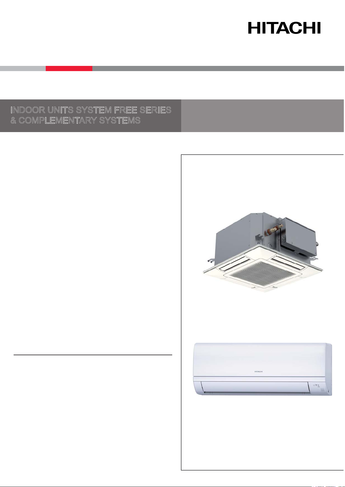
INDOOR UNITS SYSTEM FREE SERIES
& COMPLEMENTARY SYSTEMS
Service Manual
RCI - FSN4
RCIM - FSN4(E)
RCD - FSN3
RPC - FSN3(E)
RPI - FSN(3/4)(P)E(-f)
RPIM - FSN4E(-DU)
RPK - FSN(H)3M
RPF - FSN2E
RPFI - FSN2E
KPI - (E/X)4E
DX - Interface - EXV-E2
Econofresh - EF-456NE
Page 2

Page 3

Contents
Contents
General information
Unit installation
Piping work and refrigerant charge
Electrical and control settings
Control system
Optional functions
Commissioning
1
2
3
4
5
6
7
Electrical check of main parts
Servicing
Troubleshooting
Maintenance notes
8
9
10
11
I
SMGB0099 rev.0 - 12/2016
Page 4

Page 5

General Index
General Index
1. General information ................................................................................................... 1
1.1 General information ................................................................................................................................. 2
1.1.1 Introduction ...................................................................................................................................................... 2
1.2 Applied symbols ...................................................................................................................................... 3
1.3 Productclassicationandline-up ............................................................................................................ 4
1.3.1 Classicationofindoorunitmodels ................................................................................................................. 4
1.3.2 ClassicationofKPImodels ............................................................................................................................ 4
1.3.3 ClassicationofDX-Interfacemodels ............................................................................................................. 4
1.3.4 ClassicationofEconofreshmodels ............................................................................................................... 4
1.3.5 Productline-up:indoorunits ............................................................................................................................ 5
1.3.6 Productline-up:KPIenergyrecoveryunit ....................................................................................................... 9
1.3.7 Productline-up:DX-Interface .......................................................................................................................... 9
1.3.8 Productline-up:Econofresh ............................................................................................................................ 9
1.3.9 Accessory code list ........................................................................................................................................ 10
1.3.10 Multi-Kits .......................................................................................................................................................11
1.3.11 Individualremotecontrols ............................................................................................................................ 12
1.3.12 Receiverkitforcombinationwithwirelessremotecontrolswitch ................................................................ 12
1.3.13 Centralised remote controls ........................................................................................................................ 13
1.3.14 Buildingairconditioningcontrols ................................................................................................................. 13
1.3.15 Gatewaysforbuildingmanagementsystems(BMS) .................................................................................. 14
1.3.16 Controlsupportdevices ............................................................................................................................... 14
1.3.17 Control accessories ..................................................................................................................................... 15
1.3.18 OtherdevicescompatiblewithHITACHIAirConditioningsystems ............................................................. 15
2. Unit installation ........................................................................................................ 17
2.1 RCI-4-waycassette ............................................................................................................................. 19
2.1.1 Accessoriessuppliedwiththeunit ................................................................................................................. 19
2.1.2 Unit installation .............................................................................................................................................. 20
2.1.3 Airpanelinstallation:P-N23NA2 ................................................................................................................... 22
2.1.4 AccessoriessuppliedwiththeairpanelP-N23NA2 ...................................................................................... 26
2.2 RCIM-4-waycassette(compact) ......................................................................................................... 27
2.2.1 Accessoriessuppliedwiththeunit ................................................................................................................. 27
2.2.2 Unit installation .............................................................................................................................................. 28
2.2.3 Accessoriessuppliedwiththeairpanel:P-AP56NAM .................................................................................. 30
2.2.4 Air panel installation ...................................................................................................................................... 31
2.3 RCD-2-waycassette ...........................................................................................................................35
2.3.1 Accessoriessuppliedwiththeunit ................................................................................................................. 35
2.3.2 Unit installation .............................................................................................................................................. 36
2.3.3 Accessoriessuppliedwiththeairpanel:P-N23DWA/P-N46DWA ............................................................... 39
III
SMGB0099 rev.0 - 12/2016
Page 6

General Index
2.3.4 Air panel installation ...................................................................................................................................... 39
2.4 RPC-Ceiling.........................................................................................................................................41
2.4.1 AccessoriessuppliedwiththeunitRPC-FSN3 .............................................................................................. 41
2.4.2 Unit installation .............................................................................................................................................. 42
2.4.3 SuspensionbracketinstallationRPC-FSN3E ............................................................................................... 42
2.4.4 SuspensionforFSN3units ............................................................................................................................ 43
2.4.5 Indoor unit installation ................................................................................................................................... 45
2.5 RPI(M)-Ductedindoorunit(0.6-6.0)FSN4E(-DU)................................................................................48
2.5.1 Accessoriessuppliedwiththeunit ................................................................................................................. 48
2.5.2 Unit installation .............................................................................................................................................. 48
2.5.3 Air duct connection ........................................................................................................................................ 50
2.5.4 Maintenanceofthesuctionairlter ............................................................................................................... 51
2.6 RPI-Ductedindoorunit(8/10)FSN3E(-f) .............................................................................................53
2.6.1 Accessoriessuppliedwiththeunit ................................................................................................................. 53
2.6.2 Unit installation .............................................................................................................................................. 53
2.6.3 Air duct connection ........................................................................................................................................ 55
2.6.4 Maintenanceofthesuctionairlter ............................................................................................................... 55
2.7 RPI-Ductedindoorunit(16/20)FSN3PE(-f) ......................................................................................... 56
2.7.1 Unit installation .............................................................................................................................................. 56
2.8 RPK-FSN(H)3MWallmounted ............................................................................................................ 58
2.8.1 Accessoriessuppliedwiththeunit ................................................................................................................. 58
2.8.2 Unit installation .............................................................................................................................................. 58
2.8.3 Mountingbracketdimensions ........................................................................................................................ 62
2.9 RPF-Floortype,RPFI-Floorconcealedtype ..................................................................................... 64
2.9.1 Accessoriessuppliedwiththeunit ................................................................................................................. 64
2.9.2 Unit installation .............................................................................................................................................. 64
2.9.3 Changeintheairoutletdirection(RPFIunits) .............................................................................................. 66
2.9.4 RPF:OptionalPC-ARFPEremotecontrollocation ....................................................................................... 66
2.10 KPIenergyandKPIactiveunit.............................................................................................................. 67
2.10.1 Accessoriessuppliedwiththeunit ............................................................................................................... 67
2.10.2 Unit installation ............................................................................................................................................ 67
2.10.3 Ductconnection ........................................................................................................................................... 70
2.11 EconofreshKit ....................................................................................................................................... 72
2.11.1 Accessoriessuppliedwiththeunit ............................................................................................................... 72
2.11.2 Unit installation ............................................................................................................................................ 72
2.11.3 Mountingtheunit ......................................................................................................................................... 73
2.11.4 Exampleofinstallation ................................................................................................................................. 74
2.12 DX-Interface .......................................................................................................................................... 75
2.12.1 Accessoriessuppliedwiththeunit ............................................................................................................... 75
2.12.2 Unit installation ............................................................................................................................................ 75
IV
SMGB0099 rev.0 - 12/2016
Page 7

General Index
2.12.3 Mountingmethod ......................................................................................................................................... 76
2.12.4 Thermistorinstallation ................................................................................................................................. 77
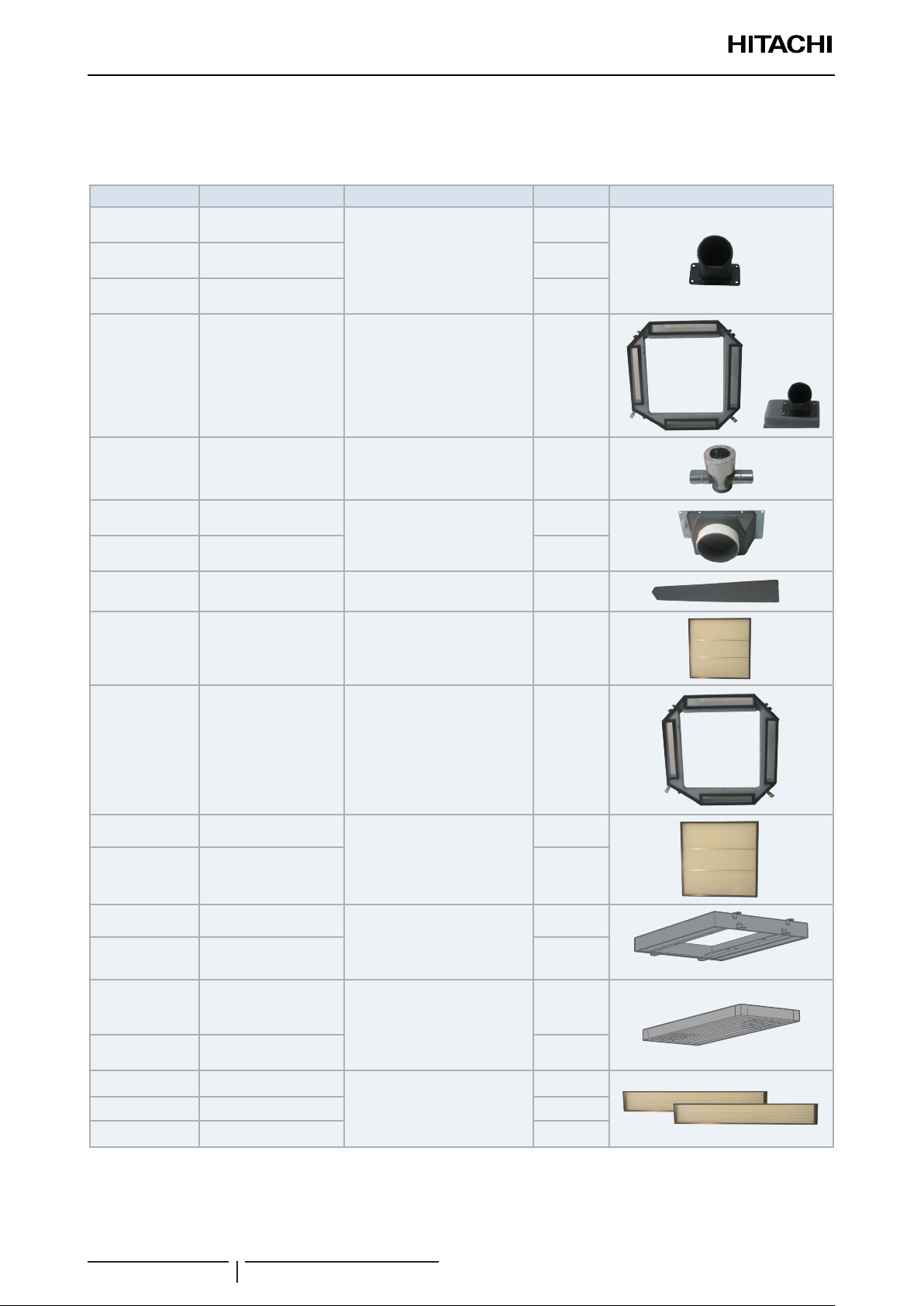
2.13 Optional accessories ............................................................................................................................. 79
2.13.1 Outdoor air inlet ........................................................................................................................................... 79
2.13.1.1 ForRCI-FSN4indoorunits:OACI-160K2andPD-75A .................................................................. 81
2.13.2 Ductadapters .............................................................................................................................................. 83
2.13.2.1 ForRCIM-FSN4(E)indoorunits:PD-75C ...................................................................................... 83
2.13.2.2 ForRCD-FSN3indoorunits:PD-150D .......................................................................................... 83
2.13.3 T-ductconnectionposition ........................................................................................................................... 84
2.13.3.1 ForRCI-FSN4indoorunits:TKCI-160k ......................................................................................... 84
2.13.3.2 Branchpipe(PDF-71C,PDF-160CI) .............................................................................................. 85
2.13.4 Outletairowinterlock ................................................................................................................................ 87
2.13.4.1 ForRCI-FSN4indoorunits:PI-160SL1 .......................................................................................... 87
2.13.5 Filterbox ...................................................................................................................................................... 89
2.13.5.1 ForRCI-FSN4indoorunits:B-160H2 ............................................................................................ 89
2.13.5.2 ForRCD-FSN3Eindoorunits:BD-90HandBD-160HD ............................................................... 90
2.13.6 Anti-bacterialter ........................................................................................................................................ 91
2.13.6.1 ForRCI-FSN4:F-160L-K ............................................................................................................... 91
2.13.6.2 ForRCD-FSN3Eindoorunits:F-90MD-K1andF-160MD-K1(Antibacteriallonglifeairlter) ...... 92
2.13.7 Deodorisinglter ......................................................................................................................................... 92
2.13.7.1 ForRCI-FSN4indoorunits:F-71L-D1andF-160L-D1 .................................................................. 92
3. Piping work and refrigerant charge ....................................................................... 95
3.1 Refrigerantpipeselection......................................................................................................................96
3.1.1 Refrigerantpipeselection .............................................................................................................................. 96
3.2 Copperpipes,sizes,connectionandinsulation .................................................................................... 97
3.2.1 Copperpipesandsizes ................................................................................................................................. 97
3.2.2 Pipe connection ............................................................................................................................................. 98
3.2.3 Insulationofmultikitsand/orbranches .......................................................................................................... 98
3.3 Generalinstructionsontheinstallationofrefrigerantpipes ..................................................................99
3.4 Copperrefrigerantpipe .......................................................................................................................100
3.4.1 Threeprinciplesonworkwithrefrigerantpipes ........................................................................................... 100
3.4.2 Preparingandcuttingcopperrefrigerationpipes ........................................................................................ 101
3.4.3 Bendingcopperpipes .................................................................................................................................. 102
3.4.4 Brazingcopperrefrigerationpipes .............................................................................................................. 103
3.4.5 Flaredconnectionmounting ........................................................................................................................ 104
3.4.6 Refrigerantpipesuspension ........................................................................................................................ 105
3.5 Refrigerantanddrainhoseinstallation ................................................................................................ 106
3.5.1 RCI-(1.0-6.0)FSN4-4-waycassette ........................................................................................................... 106
3.5.2 RCIM-(0.6-2.5)FSN4(E)-4-waycassette(compact) .................................................................................. 108
3.5.3 RCD-(0.8-6.0)FSN3-2-waycassette ......................................................................................................... 109
3.5.4 RPC-(3.0-6.0)FSN3E-Ceilingtype .............................................................................................................110
V
SMGB0099 rev.0 - 12/2016
Page 8

General Index
3.5.5 RPC-(1.5-6.0)FSN3E-Ceilingtype .............................................................................................................112
3.5.6 RPI-(0.6-1.5)FSN4E-Ductedindoorunit .....................................................................................................116
3.5.7 RPI-(2.0-6.0)FSN4E-Ductedindoorunit .....................................................................................................118
3.5.8 RPI-(8.0/10.0)FSN3E-(f)-Ductedindoorunit ............................................................................................. 120
3.5.9 RPI-(16.0/20.0)FSN3PE(-f)-Ductedindoorunit ......................................................................................... 121
3.5.10 RPIM-(0.6-1.5)FSN4E(-DU)-Ductedindoorunit ...................................................................................... 123
3.5.11 RPK-(0.6-4.0)FSN(H)3M-Walltype ......................................................................................................... 125
3.5.12 RPF(I)-(1.0-2.5)FSN2E-Floortype .......................................................................................................... 128
3.6 Refrigerantcharge...............................................................................................................................129
3.7 Precautionsintheeventofrefrigerantleaks ....................................................................................... 129
3.7.1 Maximumpermissibleconcentrationofhydrouorocarbon(HFC) .............................................................. 129
3.7.2 Calculationoftheconcentrationofrefrigerant ............................................................................................. 129
3.7.3 Countermeasuresintheeventofrefrigerantleaks ..................................................................................... 129
4. Electrical and control settings .............................................................................. 131
4.1 Unitelectricalwiringandconnection ................................................................................................... 132
4.1.1 Wiringsize ................................................................................................................................................... 132
4.1.2 Minimumrequirementsoftheprotectiondevices ........................................................................................ 133
4.1.3 Transmissionwiringbetweenoutdoorandindoorunit ................................................................................ 134
4.1.4 ElectricalconnectionofRCIunits ................................................................................................................ 134
4.1.5 ElectricalconnectionofRCIMunits ............................................................................................................. 136
4.1.6 ElectricalconnectionofRCDunits .............................................................................................................. 138
4.1.7 ElectricalconnectionofRPCunits .............................................................................................................. 140
4.1.8 ElectricalconnectionofRPIunits ................................................................................................................ 141
4.1.9 ElectricalconnectionofRPIMunits ............................................................................................................. 145
4.1.10 ElectricalconnectionofRPKunits ............................................................................................................ 147
4.1.11 ElectricalconnectionofKPIunits .............................................................................................................. 152
4.1.12 Econofreshelectricalwiringconnection .................................................................................................... 153
4.1.13 DX-Interfaceelectricalwiring ..................................................................................................................... 154
4.1.14 Networksystemconnection(CS-NETWEB) ............................................................................................ 157
4.1.15 ConnectionbetweenunitsH-LINKandH-LINKII ..................................................................................... 157
4.2 SettingofDIPswitchesandRSWswitches ........................................................................................158
4.2.1 LocationofDIPswitchesandRSWswitches .............................................................................................. 159
4.2.2 FunctionsoftheDIPswitchesandRSWswitches(Indoorunits) ................................................................ 161
4.2.3 FunctionsoftheDIPswitchesandRSWswitches(KPIunits) .................................................................... 164
4.2.4 FunctionsoftheDIPswitchesandRSWswitches(Econofreshkit) ............................................................ 166
4.2.5 FunctionsoftheDIPswitchesandRSWswitches(DX-Interface) .............................................................. 166
4.3 Wiringdiagramsforindoorunitsandcomplementarysystems ........................................................... 169
4.3.1 Wiringdiagramsforindoorunits .................................................................................................................. 169
4.3.2 Wiringdiagramsforcomplementarysystems ............................................................................................. 182
VI
SMGB0099 rev.0 - 12/2016
Page 9

General Index
5. Control system ....................................................................................................... 185
5.1 PrintedcircuitboardsforRCI-FSN4indoorunits ................................................................................ 186
5.1.1 PrintedcircuitboardsforRCI-(1.0-6.0)FSN4 .............................................................................................. 186
5.2 PrintedcircuitboardsforRCIM-FSN4(E)indoorunits ........................................................................187
5.3 PrintedcircuitboardsforRCD-FSN3indoorunits...............................................................................188
5.4 PrintedcircuitboardforRPC-FSN3E,RPF(I),units............................................................................189
5.5 PrintedcircuitboardforRPC-FSN3 .................................................................................................... 190
5.6 PrintedcircuitboardforRPI(M)-(0.6-6.0)FSN4E ................................................................................191
5.7 PrintedcircuitboardforRPI-(8.0-20.0)FSN3(P)E(-f)units .................................................................. 192
5.8 PrintedcircuitboardforRPK-FSN(H)3Munits .................................................................................... 193
5.8.1 ForRPK-(0.6-1.5)FSN(H)3M ....................................................................................................................... 193
5.8.2 ForRPK-(2.0-4.0)FSN3M ............................................................................................................................ 194
5.9 Printed circuit board for complementary systems ...............................................................................195
5.9.1 PrintedcircuitboardforKPI ........................................................................................................................ 195
5.9.2 PrintedcircuitboardforDX-Interface .......................................................................................................... 196
5.10 Safetyprotectionandcontrol............................................................................................................... 197
5.11 Indoorelectronicexpansionvalvecontrol ........................................................................................... 198
6. Optional functions ................................................................................................. 199
6.1 Indoorunitsinputandoutputsignals...................................................................................................200
6.1.1 Availableports ............................................................................................................................................. 200
6.1.2 Optionalsignalconguration ....................................................................................................................... 202
6.1.3 Programmingwithremotecontroller ........................................................................................................... 204
6.1.4 Descriptionofoptionalinputsignals ............................................................................................................ 204
6.1.5 Descriptionofoptionaloutputsignals .......................................................................................................... 208
6.2 OptionalfunctionsthroughRemotecontrol ......................................................................................... 209
6.2.1 Listofoptionalremotecontrolfunctions.(PC-ARFPE) ............................................................................... 209
6.2.2 Descriptionoftheoptionalremotecontrolfunctions(PC-ARFPE) .............................................................. 217
6.2.3 OptionalfunctionsforPC-ARHremotecontrols .......................................................................................... 225
6.2.4 Settingsonwirelessremotecontrols ........................................................................................................... 226
6.3 Complementary systems ..................................................................................................................... 227
6.3.1 KPIandDX-Interface .................................................................................................................................. 227
6.3.1.1 DX-Interface ................................................................................................................................... 228
6.3.2 EconofreshKit ............................................................................................................................................. 230
7. Commissioning ...................................................................................................... 233
7.1 Checkspriortothetestrun ................................................................................................................. 234
7.1.1 Checkpoints ................................................................................................................................................ 234
7.1.2 Checkprocedure ......................................................................................................................................... 234
VII
SMGB0099 rev.0 - 12/2016
Page 10

General Index
7.1.3 PC-ARFPEremotecontrol .......................................................................................................................... 235
7.2 Testprocedureusingthewirelessremotecontrol ............................................................................... 237
7.2.1 PC-AWRwirelessremotecontrol ................................................................................................................ 237
7.3 Testrunchecklist ................................................................................................................................ 238
8. Electrical check of main parts .............................................................................. 239
8.1 Thermistor ...........................................................................................................................................240
8.2 Electronicexpansionvalve .................................................................................................................. 240
8.3 Automaticlouvermechanism .............................................................................................................. 241
8.3.1 RCI indoor units ........................................................................................................................................... 241
8.3.2 RCIM indoor units ........................................................................................................................................ 242
8.3.3 RCDindoorunits ......................................................................................................................................... 243
8.3.4 RPC-FSN3Eindoorunits ............................................................................................................................ 244
9. Servicing ................................................................................................................. 245
9.1 RCI-(1.0-6.0)FSN4-4-waycassette ................................................................................................... 248
9.1.1 RemovingAirFilterandAirInletGrille .........................................................................................................248
9.1.2 RemovingElectricalBoxCover ................................................................................................................... 248
9.1.3 RemovingOptionalAirPanel ...................................................................................................................... 249
9.1.4 Removingturbofanandfanmotor .............................................................................................................. 250
9.1.5 RemovingPrintedCircuitBoard(PCB1) ..................................................................................................... 251
9.1.6 RemovingDrainPan ................................................................................................................................... 252
9.1.7 RemovingAntibacterialAgent .....................................................................................................................252
9.1.8 RemovingDrain-UpMechanism ................................................................................................................. 253
9.1.9 RemovingFloatSwitch ................................................................................................................................ 254
9.1.10 RemovingThermistorsforLiquidPipeandGasPipe ............................................................................... 255
9.1.11 RemovingElectronicExpansionValveCoil ............................................................................................... 256
9.1.12 RemovingAutoLouverMotors .................................................................................................................. 257
9.1.13 RemovingLouver ...................................................................................................................................... 258
9.2 RCIM-(0.6-2.5)FSN4(E)-4-waycassette(compact) .......................................................................... 259
9.2.1 Removaloftheairlter ............................................................................................................................... 259
9.2.2 Removaloftheairinletgrille ....................................................................................................................... 259
9.2.3 Removaloftheelectricalboxcover ............................................................................................................ 259
9.2.4 Removaloftheoptionalairpanel ................................................................................................................ 260
9.2.5 Removalofthefanrunnerandthefanmotor .............................................................................................. 261
9.2.6 Removaloftheprintedcircuitboard(PCB) ................................................................................................. 262
9.2.7 Removalofthedrainpan ............................................................................................................................ 263
9.2.8 Removalofthedrainmechanism ................................................................................................................ 264
9.2.9 Removaloftheoatswitch ......................................................................................................................... 264
9.2.10 Removalofthethermistorsfromtheliquidandgaspipes ........................................................................ 265
9.2.11 Removaloftheelectronicexpansionvalvecoil ......................................................................................... 265
VIII
SMGB0099 rev.0 - 12/2016
Page 11

General Index
9.2.12 Removaloftheinletairthermistor ............................................................................................................. 266
9.2.13 Removaloftheautomaticlouvermotor ..................................................................................................... 267
9.3 RCD-(0.8-6.0)FSN3-2-waycassette .................................................................................................268
9.3.1 RemovaloftheAirlterandtheAirinletgrille ............................................................................................. 268
9.3.2 Removaloftheelectricalbox ...................................................................................................................... 268
9.3.3 Removaloftheoptionalairpanel ................................................................................................................ 269
9.3.4 Removalofthefanductandthefan ........................................................................................................... 269
9.3.5 Removaloftheprintedcircuitboard(PCB) ................................................................................................. 271
9.3.6 Removaloftheoatswitch ......................................................................................................................... 272
9.3.7 Removalofthedrainmechanism ................................................................................................................ 272
9.3.8 Removalofthedrainpan ............................................................................................................................ 272
9.3.9 Removalofthethermistorsfromtheliquidandgaspipes .......................................................................... 273
9.3.10 Removaloftheelectronicexpansionvalvecoil ......................................................................................... 274
9.3.11 Removaloftheautomaticlouvermotor ..................................................................................................... 274
9.3.12 RemovetheAntibacterialagentcase ....................................................................................................... 275
9.4 RPC-(3.0-6.0)FSN3E-Ceilingtype ....................................................................................................276
9.4.1 Removaloftheairlter ............................................................................................................................... 276
9.4.2 Removalofthesidepanel ........................................................................................................................... 276
9.4.3 Removaloftheairoutletgrille ..................................................................................................................... 276
9.4.4 Removalofthefanmotor ............................................................................................................................ 277
9.4.5 Removalofthefanshaftsupport ................................................................................................................ 278
9.4.6 Removalofthecoupling .............................................................................................................................. 278
9.4.7 Removaloftheautomaticlouvermotor ....................................................................................................... 278
9.4.8 Removalofthethermistorsfromtheliquidandgaspipes .......................................................................... 279
9.4.9 Removaloftheprintedcircuitboard(PCB) ................................................................................................. 280
9.5 RPC-(1.5-6.0)FSN3-Ceilingtype ....................................................................................................... 281
9.5.1 RemovingAirFilterandAirInletGrille .........................................................................................................281
9.5.2 RemovingSideCover ................................................................................................................................. 281
9.5.3 RemovingLouver ........................................................................................................................................ 282
9.5.4 Removalofthefanmotor ............................................................................................................................ 282
9.5.5 RemovingBearing(ExceptforRPC-1.5and2.0FSN3) .............................................................................. 284
9.5.6 RemovingCoupling(ExceptforRPC-1.5and2.0FSN3) ............................................................................ 285
9.5.7 RemovingAutoLouverMotor ...................................................................................................................... 286
9.5.8 Removalofthethermistorsfromtheliquidandgaspipes .......................................................................... 286
9.5.9 RemovingElectronicExpansionValveCoil ................................................................................................. 287
9.5.10 Removaloftheprintedcircuitboard(PCB) ............................................................................................... 289
9.6 RPI-(0.6-6.0)FSN4E-Ductedindoorunit............................................................................................290
9.6.1 Removaloftheelectricalbox ...................................................................................................................... 290
9.6.2 Removaloftheinletandoutletairthermistors ............................................................................................ 291
9.6.3 Removalofthethermistorsfromtheliquidandgaspipes .......................................................................... 292
9.6.4 Removalofthefanparts ............................................................................................................................. 292
9.6.5 Removalofthedrainmechanism ................................................................................................................ 293
IX
SMGB0099 rev.0 - 12/2016
Page 12

General Index
9.6.6 Removaloftheoatswitch ......................................................................................................................... 294
9.6.7 Removaloftheairlter ............................................................................................................................... 294
9.7 RPI-(8.0-20.0)FSN3(P)E(-f)-Ductedindoorunit ................................................................................ 295
9.7.1 Removaloftheelectricalboxcover ............................................................................................................ 295
9.7.2 Removalofelectricalcomponents .............................................................................................................. 295
9.7.3 Removaloftheinletandoutletairthermistors ............................................................................................ 295
9.7.4 Removalofthethermistorsfromtheliquidandgaspipes .......................................................................... 297
9.7.5 Removalofthedrainpan ............................................................................................................................ 297
9.7.6 Fanremoval ................................................................................................................................................ 298
9.7.7 Removaloftheoatswitch ......................................................................................................................... 301
9.7.8 Removaloftheairlter ............................................................................................................................... 302
9.8 RPIM-(0.6-1.5)FSN4E-Ductedindoorunit.........................................................................................303
9.8.1 Removaloftheelectricalbox ...................................................................................................................... 303
9.8.2 Removaloftheinletandoutletairthermistors ............................................................................................ 303
9.8.3 Outletairthermistor ..................................................................................................................................... 304
9.8.4 Removalofthefanparts ............................................................................................................................. 305
9.8.5 Removaloftheoatswitch ......................................................................................................................... 306
9.8.6 Removaloftheairlter ............................................................................................................................... 306
9.9 RPK-FSN(H)3M-Wallmounted .........................................................................................................307
9.9.1 Removaloftheairlter ............................................................................................................................... 307
9.9.2 Removalofthefrontpanel .......................................................................................................................... 307
9.9.3 ElectricalBoxStructure ................................................................................................................................311
9.9.4 Removetheelectricalboxcover ................................................................................................................. 312
9.9.5 Removetheswitchcover ............................................................................................................................ 312
9.9.6 ReplacingPCB1forControl ........................................................................................................................ 313
9.9.7 RemovingElectricalBox ............................................................................................................................. 315
9.9.8 RemovingASMotor .................................................................................................................................... 317
9.9.9 RemovingDrainPan ................................................................................................................................... 317
9.9.10 RemovingHeatExchanger ....................................................................................................................... 320
9.9.11 RemovingThermistorsforFreezeProtection,GasPipe,OutletAirandInletAir ...................................... 323
9.9.12 RemovingFanandFanMotor ................................................................................................................... 327
9.9.13 RemovingElectronicExpansionValveCoil ............................................................................................... 329
9.9.14 RemovingHorizontalLouver ..................................................................................................................... 331
9.10 RPF(I)-(1.0-2.5)FSN2E-FloorandFloorconcealedtype................................................................... 332
9.10.1 Removaloftheairinletgrille ..................................................................................................................... 332
9.10.2 Removaloftheairlter ............................................................................................................................. 332
9.10.3 Removaloftheairoutletgrille ................................................................................................................... 332
9.10.4 Removalofthefrontpanel ........................................................................................................................ 333
9.10.5 Removalofthefanmotor .......................................................................................................................... 333
9.10.6 Removaloftheprintedcircuitboard(PCB) ............................................................................................... 334
9.10.7 Removalofthethermistorsfromtheliquidandgaspiping ....................................................................... 334
9.11 KPI-(252-2002)(E/X)4E-Energyrecoveryandactiveenergyrecoveryventilationunits .................... 335
X
SMGB0099 rev.0 - 12/2016
Page 13

General Index
9.11.1 Systemdescription .................................................................................................................................... 335
9.11.2 Structureandpartnames .......................................................................................................................... 335
9.11.3 Servicecoverlocation ............................................................................................................................... 335
9.11.4 RemovalofHeatExchanger ...................................................................................................................... 336
9.11.5 Removaloftheairlter .............................................................................................................................. 336
9.11.6 Removaloftheoatswitch(X4Eseriesonly) ........................................................................................... 337
9.11.7 Removalofthedampermotor ................................................................................................................... 338
9.11.8 Removaloftheelectricalbox .................................................................................................................... 339
9.11.9 RemovalofthePCB .................................................................................................................................. 339
9.11.10 Removalofthefanmotor ........................................................................................................................ 340
9.11.11 RemovaloftheDX-CoilModule(X4Eseriesonly) .................................................................................. 341
9.12 DX-Interface ........................................................................................................................................ 342
9.12.1 Structureandpartnames .......................................................................................................................... 342
9.12.2 Removaloftheelectricalcomponents ...................................................................................................... 342
10. Troubleshooting ..................................................................................................... 343
10.1 Electronicexpansionvalvecheckprocedure ...................................................................................... 344
10.2 Procedureforcheckingfanmotorsinindoorunits .............................................................................. 344
10.3 Inspectionofothercomponents .......................................................................................................... 346
10.4 Outdoor and indoor alarm codes ......................................................................................................... 347
10.5 DX-InterfaceEXV-(2.0-10.0)E2orKPI-(E/X)4Ealarmcodes..............................................................349
11. Maintenance notes ................................................................................................. 351
11.1 Regularequipmentmaintenance ........................................................................................................352
11.1.1 Necessarytools,equipmentandconsumableforregularmaintenance .................................................... 352
11.2 Indoorcleaning .................................................................................................................................... 353
11.2.1 Cleaningthebuilt-in4-wayindoorunitRCI(M) .......................................................................................... 353
11.2.2 Cleaningthebuilt-in2-wayindoorunit(RCD) ........................................................................................... 356
11.2.3 Cleaningofthewall-typeindoorunit(RPK) ............................................................................................... 358
11.2.4 CleaningtheoorconsoleandoorconcealedconsoleindoorunitRPF(I) .............................................. 359
11.2.5 Cleaningoftheceiling-typeindoorunit(RPC) .......................................................................................... 360
11.3 CleaningofKPIunits ........................................................................................................................... 363
11.4 Econofreshkit......................................................................................................................................365
11.5 Collectionofrefrigeranttoreplacetheindoorunit...............................................................................365
11.6 Cleaningagentsforheatexchanger ...................................................................................................366
11.6.1 Recommendedspecicationsofcleaningagentsforaluminiumns ........................................................ 366
11.6.2 Particularitiesandbenets ........................................................................................................................ 366
11.6.3 Toconsider ................................................................................................................................................ 366
XI
SMGB0099 rev.0 - 12/2016
Page 14

Page 15

1 General information
1. General information
Index
1.1 General information ................................................................................................................................. 2
1.1.1 Introduction ...................................................................................................................................................... 2
1.2 Applied symbols ...................................................................................................................................... 3
1.3 Productclassicationandline-up ............................................................................................................ 4
1.3.1 Classicationofindoorunitmodels ................................................................................................................. 4
1.3.2 ClassicationofKPImodels ............................................................................................................................ 4
1.3.3 ClassicationofDX-Interfacemodels ............................................................................................................. 4
1.3.4 ClassicationofEconofreshmodels ............................................................................................................... 4
1.3.5 Productline-up:indoorunits ............................................................................................................................ 5
1.3.6 Productline-up:KPIenergyrecoveryunit ....................................................................................................... 9
1.3.7 Productline-up:DX-Interface .......................................................................................................................... 9
1.3.8 Productline-up:Econofresh ............................................................................................................................ 9
1.3.9 Accessory code list ........................................................................................................................................ 10
1.3.10 Multi-Kits .......................................................................................................................................................11
1.3.11 Individualremotecontrols ............................................................................................................................ 12
1.3.12 Receiverkitforcombinationwithwirelessremotecontrolswitch ................................................................ 12
1.3.13 Centralised remote controls ........................................................................................................................ 13
1.3.14 Buildingairconditioningcontrols ................................................................................................................. 13
1.3.15 Gatewaysforbuildingmanagementsystems(BMS) .................................................................................. 14
1.3.16 Controlsupportdevices ............................................................................................................................... 14
1.3.17 Control accessories ..................................................................................................................................... 15
1.3.18 OtherdevicescompatiblewithHITACHIAirConditioningsystems ............................................................. 15
1
1
SMGB0099 rev.0 - 12/2016
Page 16

1 General information
General information
1.1 General information
©Copyright2016JohnsonControls-HitachiAirConditioningSpain,S.A.U.-Allrightsreserved.
Nopartofthispublicationmaybereproduced,copied,lmedortransmittedinanyshapeorformwithoutthepermission
ofJohnsonControls-HitachiAirConditioningSpain,S.A.U.
Withinthepolicyofcontinuousimprovementofitsproducts,JohnsonControls-HitachiAirConditioningSpain,S.A.U.
reservestherighttomakechangesatanytimewithoutpriornoticationandwithoutbeingcompelledtointroducethem
intoproductssubsequentlysold.Thisdocumentmaythereforehavebeensubjecttoamendmentsduringthelifeofthe
product.
HITACHImakeseveryefforttooffercorrect,up-to-datedocumentation.Despitethis,printingerrorscannotbecontrolled
byHITACHIandarenotitsresponsibility.
Asaresult,someoftheimagesordatausedtoillustratethisdocumentmaynotrefertospecicmodels.Noclaimswill
beacceptedbasedonthedata,illustrationsanddescriptionsincludedinthismanual.
Notypeofmodicationmustbemadetotheequipmentwithoutprior,writtenauthorizationfromthemanufacturer.
1.1.1 Introduction
HITACHIofferstheSYSTEMFREErangeofindoorunits,themainadvantageofwhichisthattheycanbecombinedwith
UTOPIAandSET-FREEseriesoutdoorunits.
Thiseliminatestheneedtoduplicatemodelsofindoorunitsandreducesstock.
SYSTEM FREE
Line up of Indoor Units
RCI-FSN4
RCIM-FSN4(E)
RCD-FSN3
RPC-FSN3
RPC-FSN3E
RPI-FSN(3/4)(P)E(-f)
RPIM-FSN4E(-DU)
RPK-FSN(H)3M
RPF-FSN2E
RPFI-FSN2E
Complementary systems
KPI-(E/X)4E
DX-InterfaceEXV-E2
EconofreshEF-456NE
? NOTE
For RCI-FSN4, RCIM-FSN4(E), RCD-FSN3 , RPC-FSN3 and RPK-FSN3M, combinations with IVX Premium and IVX Standard series 1,
as well as SET FREE FSXN1E and FSXNH(E) series, are recommended in order to obtain the maximum performance.
2
SMGB0099 rev.0 - 12/2016
Page 17

1 General information
Applied symbols
1.2 Applied symbols
Duringnormalairconditioningsystemdesignworkorunitinstallation,greaterattentionmustbepaidincertainsituations
requiringparticularcareinordertoavoiddamagetotheunit,theinstallationorthebuildingorproperty.
Situationsthatjeopardisethesafetyofthoseinthesurroundingareaorthatputtheunititselfatriskwillbeclearly
indicatedinthismanual.
Toindicatethesesituations,aseriesofspecialsymbolswillbeusedtoclearlyidentifythesesituations.
Paycloseattentiontothesesymbolsandtothemessagesfollowingthem,asyoursafetyandthatofothersdependson
it.
! DANGER
• The text following this symbol contains information and instructions relating directly to your safety and physical wellbeing.
• Not taking these instructions into account could lead to serious, very serious or even fatal injuries to you and others in the
proximities of the unit.
Inthetextsfollowingthedangersymbolyoucanalsondinformationonsafeproceduresduringunitinstallation.
! CAUTION
• The text following this symbol contains information and instructions relating directly to your safety and physical wellbeing.
• Not taking these instructions into account could lead to minor injuries to you and others in the proximities of the unit.
• Not taking these instructions into account could lead to unit damage.
Inthetextsfollowingthecautionsymbolyoucanalsondinformationonsafeproceduresduringunitinstallation.
? NOTE
• The text following this symbol contains information or instructions that may be of use or that require a more thorough explanation.
• Instructions regarding inspections to be made on unit parts or systems may also be included.
1
3
SMGB0099 rev.0 - 12/2016
Page 18

1 General information
Productclassicationandline-up
1.3 Product classication and line-up
1.3.1 Classication of indoor unit models
Unittype(indoorunit):RCI,RCIM,RCD,RPC,RPI,RPIM,RPK,RPF,RPFI
Position-separatinghyphen(xed)
Capacity(HP):0.6,0.8,1.0,1.5,2.0,2.5,3.0,4.0,5.0,6.0,8.0,10.0,16.0,20.0
FS=SYSTEMFREE
N=R410Arefrigerant
H=Hotel(RPK-(0.6-1.5)only)
2/3/4=series
P=Pair
E=MadeinEurope
M=MadeinMalaysia
–=MadeinJapanorChina
(-DU)=DrainUp(RPIMonly)
(-f)=Non-ammableinsulation(RPI-(8.0-20.0)FSN3E-fonly
XXX – X.X FS N (H) X (P) (X) (-xx)
1.3.2 Classication of KPI models
KPI-Ventilationsystem
Position-separatinghyphen(xed)
Capacity(m3/h):250,500,800,1000,1500,2000
2=1~230V50Hz
E=Energyrecovery
X=Active(Energyrecovery+DXsection)
4=series
E=MadeinEurope
KPI – (Y)YY 2 Y 4 E
1.3.3 Classication of DX-Interface models
DX-Interfacetype
Position-separatinghyphen(xed)
Capacity(HP):2.0,2.5,3.0,4.0,5.0,6.0,8.0,10.0
E=MadeinEurope
2=series
EXV – X.X E 2
1.3.4 Classication of Econofresh models
Econofreshunittype
Position-separatinghyphen(xed)
Capacity(HP):4.0,5.0,6.0
N:R410Arefrigerant
E=MadeinEurope
EF - 456 N E
4
SMGB0099 rev.0 - 12/2016
Page 19

1 General information
Productclassicationandline-up
1.3.5 Product line-up: indoor units
? NOTE
• The indoor unit models and codes are the last updated at time of publication; other previous models and coming developments could
be available for combination with the outdoor unit series.
• Check the exact classication for each unit (model, type, power and series) in “1.3.1 Classication of indoor unit models”.
RCI and RCIM indoor units
RCI RCIM
1
4-waycassette 4-waycassette(compact)
Unit Code Unit Code
RCIM-0.6FSN4(E)(*) 60278215(7E411137)
RCIM-0.8FSN4(E) 60278216(7E411100)
RCI-1.0FSN4 70405001 RCIM-1.0FSN4(E) 60278217(7E411101)
RCI-1.5FSN4 70405002 RCIM-1.5FSN4(E) 60278218(7E411102)
RCI-2.0FSN4 70405003 RCIM-2.0FSN4(E)(**) 60278219(7E411103)
RCI-2.5FSN4 70405004 RCIM-2.5FSN4(E)(**) 60278220(7E411104)
RCI-3.0FSN4 70405005
RCI-4.0FSN4 70405007
RCI-5.0FSN4 70405008
RCI-6.0FSN4 70405009
Panel Panel
P-N23NA2
(withoutMotionSensor)
70532000
P-AP56NAM
(withoutMotionSensor)
60297297
? NOTE
• The RCI and RCIM models must be used in combination with the indicated panels.
• (*): 0.6 HP Indoor Units can only be used in combination with SET FREE FSXN1E, FSXNH(E) and FSN3E series.
• (**): 1 indoor unit combinations with IVX Premium / Standard series not allowed.
5
SMGB0099 rev.0 - 12/2016
Page 20

1 General information
Productclassicationandline-up
RCD and RPC indoor units
RCD RPC
2-waycassette Ceilingtype
Unit Code Unit Code Unit Code Unit Code
RCD-0.8FSN3(*) 60278242
RCD-1.0FSN3(*) 60278243
RCD-1.5FSN3(*) 60278244 RPC-1.5FSN3 60278164
RCD-2.0FSN3(*) 60278245 RPC-2.0FSN3 60278165
RCD-2.5FSN3(*) 60278246 RPC-2.5FSN3 60278166
RCD-3.0FSN3(*) 60278247 RPC-3.0FSN3E 7E443005 RPC-3.0FSN3 60278167
RCD-4.0FSN3(*) 60278248 RPC-4.0FSN3E 7E443007 RPC-4.0FSN3 60278168
RCD-5.0FSN3(*) 60278249 RPC-5.0FSN3E 7E443008 RPC-5.0FSN3 60278169
RCD-6.0FSN3(*) 60278250 RPC-6.0FSN3E 7E443009 RPC-6.0FSN3 60278170
Panel Panel
P-AP90DNA 60297300 P-AP160DNA 60297301
? NOTE
• The RCD models must be used in combination with the indicated panels.
• (*): 1 indoor unit combinations with IVX Premium / Standard series not allowed.
6
SMGB0099 rev.0 - 12/2016
Page 21

1 General information
Productclassicationandline-up
RPI and RPIM indoor units
Unit Code Unit Code Unit Code
RPI-0.6FSN4E(*) 7E424037
RPI-0.8FSN4E 7E424013
RPI-1.0FSN4E 7E424014
RPI-1.5FSN4E 7E424015
RPI RPIM
1
Indoor ducted unit Indoorductedunit(compact)
RPIM-0.6FSN4E(*) 7E430037
RPIM-0.6FSN4E-DU(*) 7E431037
RPIM-0.8FSN4E 7E430013
RPIM-0.8FSN4E-DU 7E431013
RPIM-1.0FSN4E 7E430014
RPIM-1.0FSN4E-DU 7E431014
RPIM-1.5FSN4E 7E430015
RPIM-1.5FSN4E-DU 7E431015
RPI-2.0FSN4E 7E424016
RPI-2.5FSN4E 7E424017
RPI-3.0FSN4E 7E424018
RPI-4.0FSN4E 7E424020
RPI-5.0FSN4E 7E424021
RPI-6.0FSN4E 7E424022
RPI
Indoor ducted unit
Unit Code Unit Code Unit Code Unit Code
RPI-8.0FSN3E
RPI-10.0FSN3E
7E424010
(**)
7E424011
(**)
RPI-8.0FSN3E-f
RPI-10.0FSN3E-f
7E424410
(**)
7E424411
(**)
RPI-
16.0FSN3PE
RPI-
20.0FSN3PE
7E425038
(***)
7E425039
(***)
RPI-16.0FSN3PE-f
RPI-20.0FSN3PE-f
7E425438
(***)
7E425439
(***)
? NOTE
• (*): 0.6 HP Indoor Units can only be used in combination with SET FREE FSXN1E and FSXNH(E) series.
• (**): In combination with UTOPIA IVX Premium/Standard series: 1 indoor unit system only.
• (***): RPI-FSN3PE(-f) can only be used in combination with SET FREE FSXN1E , FSXNH(E) and FSN3 series.
7
SMGB0099 rev.0 - 12/2016
Page 22
1 General information
Productclassicationandline-up
RPK, RPF and RPFI indoor units
RPK RPF RPFI
Wall type Floortype Floorconcealedtype
Unit Code Unit Code Unit Code
RPK-0.6FSN3M(*) 60278145
RPK-0.6FSNH3M(*) 60278153
RPK-0.8FSN3M 60278146
RPK-0.8FSNH3M 60278154
RPK-1.0FSN3M 60278147
RPK-1.0FSNH3M 60278155 RPF-1.0FSN2E 7E450001 RPFI-1.0FSN2E 7E460001
RPK-1.5FSN3M 60278148
RPK-1.5FSNH3M 60278156 RPF-1.5FSN2E 7E450002 RPFI-1.5FSN2E 7E460002
RPK-2.0FSN3M 60278149 RPF-2.0FSN2E(**) 7E450003 RPFI-2.0FSN2E(**) 7E460003
RPK-2.5FSN3M 60278150 RPF-2.5FSN2E(**) 7E450004 RPFI-2.5FSN2E(**) 7E460004
RPK-3.0FSN3M 60278151
RPK-4.0FSN3M 60278152
Expansion valve kit
EV-1.5N1
(1)
(1)
60921791
? NOTE
• (*) 0.6 HP Indoor Units can only be used in combination with SET FREE FSXN1E and FSXNH(E) series.
• (**) 1 indoor unit combinations with IVX Premium / Standard series not allowed.
(1)
•
For RPK-(0.6-1.5)FSNH3M models only.
8
SMGB0099 rev.0 - 12/2016
Page 23

1 General information
Productclassicationandline-up
1.3.6 Product line-up: KPI energy recovery unit
KPI
Energyrecovery Active(EnergyRecovery+DXsection)
Unit Code Unit Code
KPI-252E4E 70603000
KPI-502E4E 70603001 KPI-502X4E 70603201
KPI-802E4E 70603002 KPI-802X4E 70603202
KPI-1002E4E 70603003 KPI-1002X4E 70603203
KPI-1502E4E 70603004
KPI-2002E4E 70603005
1
1.3.7 Product line-up: DX-Interface
Controlbox
Expansionvalvebox
1.3.8 Product line-up: Econofresh
DX-Interface
Unit Code
EXV-2.0E2 7E611000
EXV-2.5E2 7E611001
EXV-3.0E2 7E611002
EXV-4.0E2 7E611003
EXV-5.0E2 7E611004
EXV-6.0E2 7E611005
EXV-8.0E2 7E611006
EXV-10.0E2 7E611007
Econofresh
Unit Code
EF-456NE 7E560000
? NOTE
The EF-456NE unit can only be installed in combination with the following units (Sales from April 2014):
• RPI-4.0FSN4E (7E424020)
• RPI-5.0FSN4E (7E424021)
• RPI-6.0FSN4E (7E424022)
9
SMGB0099 rev.0 - 12/2016
Page 24
1 General information
Productclassicationandline-up
1.3.9 Accessory code list
HITACHIhasawiderangeofaccessoriesandremotecontrolsystemsthatcanbeusedwiththeSETFREEandUTOPIA
outdoorunits.ConsulttheTechnicalCatalogueforcontrolsandforthecorrespondingoutdoorunits.
Name Unit Reference Description Code Figure
PD-75A RCI-FSN4
PD-75C RCIM-FSN4(E) 60292014
PD-150D RCD-FSN3 60292064
OACI-160K2 RCI-FSN4 Freshoutdoorairintakekit 60291761
TKCI-160K RCI-FSN4
PDF-71C1 RCI-(1.0-2.5)FSN4
PDF-160C1 RCI-(3.0-6.0)FSN4 60299437
PI-160LS1 RCI-FSN4 3-wayoutletpartsset 60291756
F-160LK RCI-FSN4
Ductadapter
forfreshoutdoorairintakekit
T-shapedductconnectionkit
forfreshoutdoorairintakeki
Ductconnectingangefor
indoor air outlet
Antibacteriallonglifeairlter
(installationonthepanel)
60291763
60291762
60299436
60291760
B-160H2 RCI-FSN4
F-71L-D1 RCI-(1.0-2.5)FSN4
F-160L-D1 RCI-(3.0-6.0)FSN4 60291758
B-90HD RCD-(0.8-3.0)FSN3
B-160HD RCD-(4.0-6.0)FSN3 60292062
F-90MD-K1 RCD-(0.8-3.0)FSN3
F-160MD-K1 RCD-(4.0-6.0)FSN3 60292059
F-56LPC1 RPC-(1.5-2.0)FSN3
F-90LPC1 RPC-(2.5-3.0)FSN3 60299280
F-160LPC1 RPC-(4.0-6.0)FSN3 60299281
(Adapterfordeodorisinglter)
(installationontheFilterBox
(Adapterforantibacteriallong
Antibacteriallonglifeairlter
(installationonthelterbox
(Installationontheindoorunit)
FilterBox
Deodorantairlter
B-160H2)
FilterBox
lifeairlter)
highperformancelter
F-90MD-K1→B-90HD
F-160MD-K1→B-160HD)
Longlifelter
60291759
60291757
60292061
60292058
60299279
10
SMGB0099 rev.0 - 12/2016
Page 25

1 General information
Productclassicationandline-up
Name Unit Reference Description Code Figure
DUPC-63K1
DUPC-71K1 60291936
DUPC-160K1 60291937
PS-MSK2 RCI-FSN4
SOR-NEP RPC-FSN3 60291825
SOR-NEC RCIM-FSN4(E) 60292011
SOR-NED RCD-FSN3 60292055
SLT-30-200-L600
SLT-30-250-L600 70550201
SLT-30-300-L600 70550202
SLT-30-355-L600 70550203
HEF-252
HEF-502 70552202
RPC-FSN3 Drain-upMechanism
Motionsensorkit
KPI Noise damper
60291935
70590903
70550200
70552201
1
HEF-802 70552203
KPI Highefciencylter
HEF-1002 70552204
HEF-1502 70552205
HEF-2002 70552206
1.3.10 Multi-Kits
Name Unit Reference Description Code Figure
E-102SN4
E-162SN4 70524202
E-242SN3 70524104
E-302SN3 70524105
E-52XN3 70525100
SETFREE LineBranch
E-102XN3 70525101
E-162XN3 70525102
E-202XN3 70525103
E-242XN3 70525104
70524201
E-322XN3 70525106
MH-84AN1
MH-108AN 70522008
MH-108XN 70523108
SETFREE HeaderBranch
11
SMGB0099 rev.0 - 12/2016
70522009
Page 26

1 General information
Productclassicationandline-up
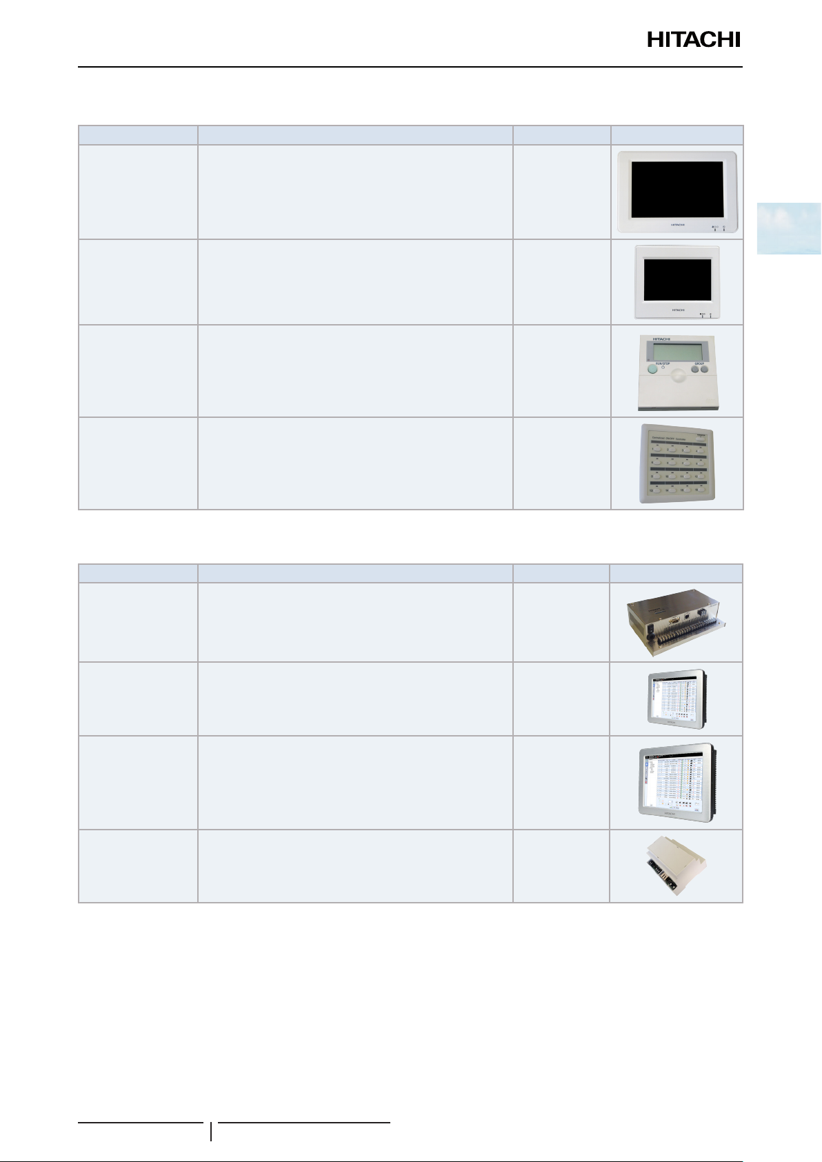
1.3.11 Individual remote controls
Name Description Code Figure
PC-ARFPE Remotecontrolwithtimer 70510002
PC-ARH Simpliedremotecontrol 60291486
PC-AWR Wireless remote control 60291056
1.3.12 Receiver kit for combination with wireless remote control switch
Receiver kit name Indoor Unit application
PC-ALH3 RCI-FSN4 PC-AWR 60291767
PC-ALHC1 RCIM-FSN4(E) PC-AWR 60292003
PC-ALHD1 RCD-FSN3 PC-AWR 60292053
PC-ALHP1 RPC-FSN3 PC-AWR 60291823
PC-ALHZ
PC-ALHZF
RPI-FSN(3/4)(P)E,
RPIM-FSN4E(-DU),
RPF(I)-FSN2E
RCI-FSN4,
RCIM-FSN4(E),
RCD-FSN3,
RPK-FSN(H)3M
RPC-FSN3
Compatible Wireless
remote control
PC-AWR 60291473
PC-AWR 60291789
Code Figure
onthepanel
onthewall
12
SMGB0099 rev.0 - 12/2016
Page 27
1 General information
Productclassicationandline-up
1.3.13 Centralised remote controls
Name Description Code Figure
PSC-A64GT Touchscreencentralstation 60291730
PSC-A32MN Touchscreencentralstationmini 60291966
PSC-A64S Centralised remote control 60291479
1
PSC-A16RS CentralisedON/OFFcontrol 60291484
1.3.14 Building air conditioning controls
Name Description Code Figure
CSNETWEB
(PSC-A160WEB1)
CSNETManagerLT
CSNETManagerXT
HC-A64NET
CentralisedcontrolsystemwhichrunsCSNETWEBsoftware
tocontroltheindoorunits
Centralisedcontrolwithatouchinterfaceof12incheswhich
runsCSNETMANAGERsoftwaretocontroltheindoorunits.
Centralisedcontrolwithatouchinterfaceof17incheswhich
runsCSNETMANAGERsoftwaretocontroltheindoorunits.
H-LINKgatewayusedbyCSNETMANAGERScreensto
communicatewithindoorunits
(Max.64indoorunits)
7E512000
7E512201
7E512202
7E512200
13
SMGB0099 rev.0 - 12/2016
Page 28

1 General information
Productclassicationandline-up
1.3.15 Gateways for building management systems (BMS)
Name Description Code Figure
HC-A8MB
HC-A64MB
Integrationwithinstallationwithintelligentcontrol(Building
ManagementSystem)GatewayInterfacetoMODBUS
systems(Max.8indoorunits).
Integrationwithinstallationwithintelligentcontrol(Building
ManagementSystem)GatewayInterfacetoMODBUS
systems(Max.64indoorunits).
7E513204
7E513205
HC-A16KNX
KNX001
HARC-BXE(A)
HARC-BXE(B)
Integrationwithinstallationswithintelligentcontrol(BMS).
GatewayInterfacetoKNXsystems.
Integrationwithinstallationswithintelligentcontrol(BMS)
throughCSNETWEB.GatewayInterfacetoKNXsystems.
Integrationwithinstallationwithintelligentcontrol(Building
ManagementSystem)GatewayInterfacetoLONWORKS
systems.(H-LINKIcommunication)(Max.64unitswith8
Integrationwithinstallationwithintelligentcontrol(Building
ManagementSystem)GatewayInterfacetoLONWORKS
systems.(H-LINKIcommunication)(Max.32unitswith16
1.3.16 Control support devices
Name Description Code Figure
7E513300
7E5121000
60290874
parameters)
60290875
parameters)
PSC-A1T Programmabletimer 60291482
PSC-6RAD H-LINKRACAdapter 60063017
PC-A1IO IntegrationofexternalequipmentintoH-LINK 7E519000
PSC-5HR H-LINKRelay 60291105
THM-R2AE Remotetemperaturesensor(THM4) 7E299907
14
SMGB0099 rev.0 - 12/2016
Page 29

1 General information
Productclassicationandline-up
1.3.17 Control accessories
Name Description Code Figure
Wall support
Standsupport
PCC-1A Optional function connector 70590901
PRC-10E1 2P-Extensioncord(10metres) 7E790211
PRC-15E1 2P-Extensioncord(15metres) 7E790212
PRC-20E1 2P-Extensioncord(20metres) 7E790213
PRC-30E1 2P-Extensioncord(30metres) 7E790214
NetCongurationKit NetcongurationkitforHC-A(8/64)MBandHC-A64NET 7E512306
Wall mounted support
(forbothCSNETMANAGERLT/XT)
Standmountedsupport
(forbothCSNETMANAGERLT/XT)
7E512300
7E512301
1.3.18 Other devices compatible with HITACHI Air Conditioning systems
InadditiontoalltheaforementionedHITACHIcontrols,therearesomenon-HITACHIdevicesforcombinationwith
HITACHIAirConditioningsystems.Thesearethefollowing:
• HITACHI-AIRZONEgateway(HTI11001):ApplicabletoHITACHIRPI(M)unitsprovidingcompatibilitywiththe
AIRZONEsystems,zone-basedclimate-controlsystems.
• Powermeter:SiemenspowermeterforCSNETWEBandCSNETManager.
• MODBUS-BACNETgateway:SolutionofferedbyIntesisSoftwarecompanywhichtransfersMODBUSdatainto
BACNETdata.
• MODBUS-FIDELIOgateway:SolutionofferedbyIntesisSoftwarecompanywhichtransfersMODBUSdatainto
FIDELIOdata.
1
15
SMGB0099 rev.0 - 12/2016
Page 30

Page 31

2 Unit installation
2. Unit installation
Index
2.1 RCI - 4-way cassette ............................................................................................................................. 19
2.1.1 Accessories supplied with the unit ................................................................................................................. 19
2.1.2 Unit installation .............................................................................................................................................. 20
2.1.3 Air panel installation: P-N23NA2 ................................................................................................................... 22
2.1.4 Accessories supplied with the air panel P-N23NA2 ...................................................................................... 26
2.2 RCIM - 4-way cassette (compact) ......................................................................................................... 27
2.2.1 Accessories supplied with the unit ................................................................................................................. 27
2.2.2 Unit installation .............................................................................................................................................. 28
2.2.3 Accessories supplied with the air panel: P-AP56NAM .................................................................................. 30
2.2.4 Air panel installation ...................................................................................................................................... 31
2.3 RCD - 2-way cassette ...........................................................................................................................35
2.3.1 Accessories supplied with the unit ................................................................................................................. 35
2.3.2 Unit installation .............................................................................................................................................. 36
2.3.3 Accessories supplied with the air panel: P-N23DWA / P-N46DWA ............................................................... 39
2.3.4 Air panel installation ...................................................................................................................................... 39
2.4 RPC - Ceiling.........................................................................................................................................41
2.4.1 Accessories supplied with the unit RPC-FSN3 .............................................................................................. 41
2.4.2 Unit installation .............................................................................................................................................. 42
2.4.3 Suspension bracket installation RPC-FSN3E ............................................................................................... 42
2.4.4 Suspension for FSN3 units ............................................................................................................................ 43
2.4.5 Indoor unit installation ................................................................................................................................... 45
2
2.5 RPI(M) - Ducted indoor unit (0.6-6.0)FSN4E(-DU)................................................................................48
2.5.1 Accessories supplied with the unit ................................................................................................................. 48
2.5.2 Unit installation .............................................................................................................................................. 48
2.5.3 Air duct connection ........................................................................................................................................ 50
2.5.4 Maintenance of the suction air lter ............................................................................................................... 51
2.6 RPI - Ducted indoor unit (8/10)FSN3E(-f) .............................................................................................53
2.6.1 Accessories supplied with the unit ................................................................................................................. 53
2.6.2 Unit installation .............................................................................................................................................. 53
2.6.3 Air duct connection ........................................................................................................................................ 55
2.6.4 Maintenance of the suction air lter ............................................................................................................... 55
2.7 RPI - Ducted indoor unit (16/20)FSN3PE(-f) ......................................................................................... 56
2.7.1 Unit installation .............................................................................................................................................. 56
2.8 RPK - FSN(H)3M Wall mounted ............................................................................................................ 58
2.8.1 Accessories supplied with the unit ................................................................................................................. 58
17
SMGB0099 rev.0 - 12/2016
Page 32

2 Unit installation
2.8.2 Unit installation .............................................................................................................................................. 58
2.8.3 Mounting bracket dimensions ........................................................................................................................ 62
2.9 RPF - Floor type, RPFI - Floor concealed type ..................................................................................... 64
2.9.1 Accessories supplied with the unit ................................................................................................................. 64
2.9.2 Unit installation .............................................................................................................................................. 64
2.9.3 Change in the air outlet direction (RPFI units) .............................................................................................. 66
2.9.4 RPF: Optional PC-ARFPE remote control location ....................................................................................... 66
2.10 KPI energy and KPI active unit..............................................................................................................67
2.10.1 Accessories supplied with the unit ............................................................................................................... 67
2.10.2 Unit installation ............................................................................................................................................ 67
2.10.3 Duct connection ........................................................................................................................................... 70
2.11 Econofresh Kit ....................................................................................................................................... 72
2.11.1 Accessories supplied with the unit ............................................................................................................... 72
2.11.2 Unit installation ............................................................................................................................................ 72
2.11.3 Mounting the unit ......................................................................................................................................... 73
2.11.4 Example of installation ................................................................................................................................. 74
2.12 DX-Interface .......................................................................................................................................... 75
2.12.1 Accessories supplied with the unit ............................................................................................................... 75
2.12.2 Unit installation ............................................................................................................................................ 75
2.12.3 Mounting method ......................................................................................................................................... 76
2.12.4 Thermistor installation ................................................................................................................................. 77
2.13 Optional accessories ............................................................................................................................. 79
2.13.1 Outdoor air inlet ........................................................................................................................................... 79
2.13.1.1 For RCI-FSN4 indoor units: OACI-160K2 and PD-75A .................................................................. 81
2.13.2 Duct adapters .............................................................................................................................................. 83
2.13.2.1 For RCIM-FSN4(E) indoor units: PD-75C ...................................................................................... 83
2.13.2.2 For RCD-FSN3 indoor units: PD-150D .......................................................................................... 83
2.13.3 T-duct connection position ........................................................................................................................... 84
2.13.3.1 For RCI-FSN4 indoor units: TKCI-160k ......................................................................................... 84
2.13.3.2 Branch pipe (PDF-71C, PDF-160CI) .............................................................................................. 85
2.13.4 Outlet air ow interlock ................................................................................................................................ 87
2.13.4.1 For RCI-FSN4 indoor units: PI-160SL1 .......................................................................................... 87
2.13.5 Filter box ......................................................................................................................................................89
2.13.5.1 For RCI-FSN4 indoor units: B-160H2 ............................................................................................ 89
2.13.5.2 For RCD-FSN3E indoor units: BD-90H and BD-160HD ............................................................... 90
2.13.6 Anti-bacteria lter ........................................................................................................................................ 91
2.13.6.1 For RCI-FSN4: F-160L-K ............................................................................................................... 91
2.13.6.2 For RCD-FSN3E indoor units: F-90MD-K1 and F-160MD-K1 (Antibacterial long life air lter) ...... 92
2.13.7 Deodorising lter ......................................................................................................................................... 92
2.13.7.1 For RCI-FSN4 indoor units: F-71L-D1 and F-160L-D1 .................................................................. 92
18
SMGB0099 rev.0 - 12/2016
Page 33

2 Unit installation
RCI - 4-way cassette
2.1 RCI - 4-way cassette
2.1.1 Accessories supplied with the unit
Check that the following accessories are supplied with the unit.
? NOTE
Please contact your HITACHI distributor if any of the accessories has not been supplied with the unit.
RCI-FSN4 indoor unit
Accessory Quantity Purpose
Pattern (Carton Board) 1
Checking pattern
(Cut out from the carton board)
Washer with insulation (M10) 4
Washer (M10) 4
Drain hose 1
Wire clamp 1
Pipe insulation 1
Pipe insulation 1
Cord band 2
Cord band 6
2
For adjusting space of false ceiling opening
and position of the unit
1
For unit installation
For drain hose connection
For refrigerant piping connection
For xing remote control switch wiring,
louver sensor and insulation of piping
Insulation (5Tx50x200) 1 For covering wiring connection
Insulation (5Tx270x270) 1 For covering drain connection
Applicable panel
Indoor unit Applicable panel
RCI-(1.0-6.0)FSN4
P-N23NA2
(without motion sensor)
19
SMGB0099 rev.0 - 12/2016
Page 34

2 Unit installation
(mm)
RCI - 4-way cassette
2.1.2 Unit installation
Initial checks
Install the indoor unit with a proper clearance around it paying careful attention of installation direction for the piping,
wiring and maintenance working space, as shown below.
Provide a service access door near the unit piping connection area on the ceiling.
Piping
Connection
Service
Access Door
Service Access
Door
Drain Piping
Connection
Check space between ceiling and false ceiling is enough as indicated below.
Check the ceiling surface is at for the air panel installation work.
Clearance: 10-20mm
Unit High
In False Ceiling
Unit HP A(mm)
RCI-1.0 to 2.5HP 238
RCI-3.0 to 6.0HP 238
Opening of false ceiling
Cut out the area for the indoor unit in the false ceiling and install suspension bolts, as shown below:
Dimension of opening 860 to 910
20 20
(Unit size)
840
760
(Dimension of
suspension bolts)
Holes (for
suspension bolt)
4-12 x32
2020
760
bolts)
840 (Unit size)
(Dimension of suspension
Piping connection
side
Drain piping
connection side
4-Positions of suspension
bolts (M10 or W3/8)
(Field-supplied)
Check to ensure that the ceiling is horizontally level, otherwise water can not ow.
Strengthen the opening parts of the false ceiling.
20
SMGB0099 rev.0 - 12/2016
Dimension of opening 860 to 910
Page 35

2 Unit installation
RCI - 4-way cassette
Mounting of suspension bolts
Mount suspension bolts using M10 (W3/8) as size, as shown.
For concrete slab: For steel beam:
Insert
(100 to 150Kg)
Concrete
Anchor Bolt (W3/8 or M10)
I-Beam
Suspension Bolt
(w3/8 or M10)
Mounting of indoor unit
150 to 160mm
Steel
Mount the nuts and the washers to the suspension bolts. Put the washer so that the surface with insulation can faces
downwards as shown below:
Suspension Bolts (eld-supplied)
Washer with Insulation (accessory)
Suspension Bracket (attached indoor unit)
Nut (eld-supplied)
Washer (accessory)
Nut (eld-supplied)
(mm)
Surface of ceiling
100
50
Aprox.
50
Aprox.
2
Consider piping connection side before lift indoor unit.
Lift the indoor unit by hoist, and do not put any force on the drain pain.
Secure the indoor unit using the nuts, washers.
Suspension bolt
Suspension
bracket
Drain pan
? NOTE
• If a false ceiling has already been installed, complete all piping and wiring work inside the ceiling before hooking-up the indoor unit.
• Secure the indoor unit using the nuts, at washers and spring washers. (These nuts and washers are supplied, 4 pieces each).
Adjusting the space between indoor units and false ceiling opening
Adjust the indoor unit to the correct position while checking with the pattern for installation.
Checking pattern for
dimension of opening
Pattern board for installation
21
SMGB0099 rev.0 - 12/2016
Packing (Corrugated board)
Page 36

2 Unit installation
P-AP160NA1
RCI - 4-way cassette
For ceiling already completed with panels
Attach this side of the checking
pattern to the inner side of the
opening of the ceiling
Indoor
unit
Attach this side of the
checking pattern to the lower
side of the unit
Indoor unit
Attach this side
of the checking
pattern to the outer
side of the unit
Check the dimension
of opening at each
side of the unit
Ceiling not completed with panels yet
Checking
pattern
Suspension bolt
Ceiling
panel
Pattern paper for installation
Dimension
for opening
Unit
Checking
pattern
Check the height of
the ceiling at each
corner of the unit
Dimension
for opening
Attach this side of
the checking pattern
to the ceiling panel
Tighten the nuts of the suspension brackets after the adjustment is completed. Apply LOCK-TIGHT paint to the bolts and
nuts in order to prevent them from loosening. If not done, abnormal noises or sounds may occur and the indoor unit may
come loose.
2.1.3 Air panel installation: P-N23NA2
1 Push both ends of knobs at the air inlet grille toward the arrow direction, open the air inlet grille until the angle of
2 Lift the grille keeping it inclined.
3 Draw the grille towards the open space after lifting.
Surface of ceiling
Removing Air Intake Grille from Air Panel
Pattern board for installation
Screw (M6)
approximately 45° from the air panel surface. After lifting the air inlet grille keeping it inclined, draw the air inlet grille
forward. (Remove the lament tape (4 portions) xing the air lter).
Air panel
Air inlet grille
45°
Corner pocket
cover (4 portions)
Knob
Supporting string
22
SMGB0099 rev.0 - 12/2016
Page 37

2 Unit installation
A
RCI - 4-way cassette
? NOTE
Perform the attaching work in the reverse procedure of removing for install the air intake grille. The air inlet grille can be attached from
any 4 directions by rotating it. The air intake grille direction can be selected freely.
Installing Air Panel
1 Remove the cover of the corner pocket (4 portions). Remove pulling A part toward the arrow direction.
2 Pull down the U-shaped hook (at 2 positions) located at the indoor unit side.
3 Mount the air panel temporarily. Fit the corner position of the refrigerant pipe connection at the indoor unit and the
position stamped as “Ref. Pipe ”. Then, catch the C-shaped hinges (2 portions) onto the U-shaped hooks (2 portions).
4 Fix the air panel to the xing plate by factory supplied long screws (M6 cross screws).
Electrical box
Indoor unit
2
Refrigerant pipe
connections
U-shaped hook
Stamp refrigerant pipe
C-shaped hinge
5 Tighten the long screws until touching the stopper to the xing plate. Check to ensure that the distance between the
xing plate under-surface and the corner panel under-surface is 26mm.
6 When tightening the long screws to prevent air leakage and to be no gap between the false ceiling surface and the
indoor unit, the inner circumference of the air panel (the position to attach the air inlet grille) may be slightly deformed.
However, it is not abnormality.
Long screws (Q'ty 4)
Fixing plate
Air panel
Indoor unit
Fixing plate
(indoor unit)
0
+5
12
26
Corner
panel
Long screw
23
SMGB0099 rev.0 - 12/2016
False ceiling
Page 38

2 Unit installation
RCI - 4-way cassette
! CAUTION
• If tighten long screws insufcient, may cause something wrong as below.
Air Leakage
Smudge
• If any gap has even though tighten long screws sufcient, readjust the height of indoor unit.
No gap shall exist
• It’s able to adjust the indoor unit height by using wrench from the corner pocket.
Wrench
• Too considerable adjustment of height cause dewing from drain-pan.
• Do not turn the air louver by hand. If moved, the louver mechanism would be damaged.
Dewing
Attachment of Corner Pocket Cover
Attach the corner pocket covers after the air panel is completely assembled.
1 Catch the band at the rear side of the corner pocket cover
onto the projection at the air panel as shown.
Band
Fixing hook
2 Insert and push the xing hooks (2 portions) at Ⓐ to the
air panel and insert and push the xing hook (1 portion) at
Ⓑ to the air panel.
Projection
A
A
A
Fixing hook
B
B
24
SMGB0099 rev.0 - 12/2016
Page 39

2 Unit installation
RCI - 4-way cassette
Attachment of corner pocket cover with motion sensor PS-MSK2 on the air panel model
P-N23NA2
The corner pocket cover with motion sensor can be attached to any of corners. Determine the attaching place as user’s
request.
1 Connect the relay wire (attached in the air panel) to CN10 in the electrical box.
Projection
Band
Corner pocket cover
with motion sensor
Air panel
Corner pocket
Relay wire
2
Relay
connector
2 Run the relay wire to the corner pocket cover with motion sensor through the top of xing plate for the indoor units.
Set a length of 100mm to 200mm from the indoor unit to the relay connector.
Relay wire
Indoor unit wiring
connection
Relay connector
3 Clamp the extra length of the relay wire by the cord band and store it at inside the ceiling.
a. Draw out the relay wire from the corner pocket of the air panel. Connect the wiring for motion sensor at the corner
pocket cover to the relay connector. After connecting, cover the relay connector connection by the wiring cover
and x the wiring cover by the plastic bands.Catch the band at the rear side of the corner pocket cover with
motion sensor onto the projection at the air panel.
Plastic band
Wiring cover
Plastic band
Fixing plate
100~200mm
b. While pushing the wiring into the corner pocket, insert the xing hooks (2 portions) at Ⓐ to the square hole at the
air panel, and push the corner pocket cover. Then, insert and push the xing hook (1 portion) at Ⓑ to the square
hole at the air panel.
? NOTE
• Catch securely the band onto the projection. If not, the comer pocket cover may fall down when removing it so that may cause
injury.
• Catch securely the xing hooks of the corner pocket cover to the air panel. If not, the xing hooks will be damaged.
25
SMGB0099 rev.0 - 12/2016
Page 40

2 Unit installation
RCI - 4-way cassette
Electrical connection of the air panel
1 The following connectors are used in the air panel. Remove the tape xing the wiring connectors on the air panel and
pull out them as shown in the gure below. Connect them with the wiring connectors on the indoor unit.
Condition without air
intake grille
>PS<
HS-HB
Electrical box
Motor wiring for auto louver
(on air panel) (connector for
low voltage: 18 poles, white)
Motor wiring for auto louver (on
indoor unit) (Connector for low
voltage: 18 poles, white)
2 After completing the wiring connection of the air panel, attach the air inlet grille. Perform the attaching work in the
reverse procedure of removing.
2.1.4 Accessories supplied with the air panel P-N23NA2
Check that the following accessories are supplied with the unit.
? NOTE
Please contact your HITACHI distributor if any of the accessories has not been supplied with the unit.
Accessory Appearance Quantity Purpose
Long bolt (M6 x 50)
4 For panel xing
26
SMGB0099 rev.0 - 12/2016
Page 41

2 Unit installation
Q'ty
Purpose
1
For Adjusting Space of False
Ceiling Opening and
Q'ty
Purpose
4
1
For Adjusting Space of False
Ceiling Opening and
Position of the Unit
For Fitting Paper Pattern
Q'ty
Purpose
4
4
1
For Adjusting Space of False
Ceiling Opening and
Position of the Unit
For Fitting Paper Pattern
Q'ty
Purpose
4
4
4
1
For Adjusting Space of False
Ceiling Opening and
Position of the Unit
For Fitting Paper Pattern
For Unit Installation
Q'ty
Purpose
4
4
4
1
1
For Adjusting Space of False
Ceiling Opening and
Position of the Unit
For Fitting Paper Pattern
For Unit Installation
Q'ty
Purpose
4
4
4
1
1
1
For Adjusting Space of False
Ceiling Opening and
Position of the Unit
For Fitting Paper Pattern
For Unit Installation
For Drain Hose Connection
Q'ty
Purpose
4
4
4
2
6
1
1
1
1
1
1
For Adjusting Space of False
Ceiling Opening and
Position of the Unit
For Fitting Paper Pattern
For Unit Installation
For Refrigerant Piping
Connection
For Drain Hose Connection
For Fixing Remote Control
Switch Wiring, Louver Sensor
and Insulation of Piping
For Covering Wiring
Connection
Q'ty
Purpose
4
4
4
2
6
1
1
1
1
1
1
1
For Adjusting Space of False
Ceiling Opening and
Position of the Unit
For Fitting Paper Pattern
For Unit Installation
For Refrigerant Piping
Connection
For Drain Hose Connection
For Fixing Remote Control
Switch Wiring, Louver Sensor
and Insulation of Piping
For Covering Drain
Connection
For Covering Wiring
Connection
Q'ty
Purpose
4
4
4
2
6
1
1
1
1
1
1
1
1
For Adjusting Space of False
Ceiling Opening and
Position of the Unit
For Fitting Paper Pattern
For Unit Installation
For Refrigerant Piping
Connection
For Drain Hose Connection
For Fixing Remote Control
Switch Wiring, Louver Sensor
and Insulation of Piping
For Covering Drain
Connection
For Covering Wiring
Connection
For Covering Drain
Connection
RCIM - 4-way cassette (compact)
2.2 RCIM - 4-way cassette (compact)
2.2.1 Accessories supplied with the unit
Check to ensure that the following accessories are supplied with the unit.
? NOTE
• Contact your HITACHI distributor if any of the accessories have not been supplied with the unit.
• The hose clamp, screws, washers and plastic cord clamps are placed together with the pipe insulation.
• The air panel, remote control switch and branch pipes are not included as they are optional accessories.
Accessory Appearance Quantity Purpose
Checking scale
(cut and take it out from the carton board)
Cross recessed head screws (M5)
Washer with insulation material (M10)
Washer (M10)
Drain hose
Hose clamp
Insulation
(5Tx50x200)
Insulation
(5Tx100x500)
Insulation
(5Tx25x500)
27
SMGB0099 rev.0 - 12/2016
For adjusting space of false ceiling opening
1
and position of the unit
4 For tting paper pattern
4
For unit installation
4
1
For drain hose connection
1
1 For covering wiring connection
1 For covering drain connection
1 For covering drain connection
2
Page 42

2 Unit installation
Min. 500 Min. 100
RCIM - 4-way cassette (compact)
2.2.2 Unit installation
Initial checks
Check that there is enough space between the false ceiling and the
ceiling of the room to house the unit. Its height must be less than
the measured distance. Consult the corresponding chapter of the
Technical Catalogue for information on the unit measurements.
Clearance: Min. 30 mm
Unit height:
285 in false ceiling
Before starting installation, plan the direction of the pipes and wiring required. Also bear in mind that there must be
enough space around the unit for installation and maintenance.
When equipping the duct adapter (optional), set up a service access door at the duct adapter side in order to install the
duct adapter. Refer to the installation manual of the duct adapter for details.
Install a service hatch near the pipe connection area and electrical junction box for installation and maintenance work.
Distance from wall side
1 1 1
1 Access door for duct adapter (optional)
2 Service access door.
3 Electrical Box
4 Piping connection.
Min.
1500
Min.
1500
Minimum service space
Min.
1500
Min.
1500
2 2 23 3 34 4 4
Min.
1500
Min.
1500
Min.
1500
Min.
3000
Min.
1500
Min.
1500
Min.
1500
Piping connection side
Check that the drain hose can be installed maintaining the necessary downward slope (1/25 to 1/100).
Check that the ceiling surface where the air panel is to be installed is completely horizontal.
? NOTE
In the case installing the indoor unit to a grid ceiling,
do not touch the unit body, the electrical wiring and
refrigerant piping to a suspension bolt of a grid. Check
the location of suspension bolts of a grid ceiling and
indoor unit mounting position before installing of the
indoor unit.
Min. 1000
Min. 500
Grid ceiling
Drain piping
Down slope
Pitch: 1/25 to 1/100
Suspension bolt for grid ceiling
Min.
2400
Suspension bolt
for Indoor unit
28
SMGB0099 rev.0 - 12/2016
Page 43

2 Unit installation
3
RCIM - 4-way cassette (compact)
Installation
Cut the area of the unit in the false ceiling and reinforce the opening made.
Install the M10 (3/8”) suspension bolts depending on the type of surface:
Dimension of opening:
suspension bolts: 530
Piping connection
side
Steel beam
580 (576~590)
Unit size: 570
Dimension of
4-positions of
suspension bolts
1 150 to 160 mm
2 Steel
Concrete beams
3 Anchor bolt (W3/8 or M10)
4 Concrete
5 Insert (100 to 150 kg)
1
Unit size: 570
Dimension of
suspension bolts: 530
Optional panel
Drain piping
connection side
Steel beams Wooden beams
Anchor bolt
(W3/8 or M10)
580 (576~590)
Dimension of opening:
2
2
5
4
Wooden bar
(60 mm to 90 mm
square)
Wooden beam
1 Suspension bolts (eld-supplied)
2 Nut (eld-supplied)
3 Washer with insulation accessory
4 Suspension bracket (attached indoor unit)
Approx 50 mm
5 Washer (accessory)
6 Nut (eld-supplied)
7 Ceiling
Approx 45 mm
Thread on the nuts and t the washers for all the bolts, as shown in the gure.
Fit two suspension brackets onto the nut and washer of each bolt, starting on one side.
Check that the nuts and washers are correctly secured with the suspension bracket retainers and t the brackets onto
their nuts and washers on the other side.
Fit the washers with the insulation facing downwards, as shown in the gure. Bear in mind the position of the side for
pipe connection before lifting the indoor unit.
Where a false ceiling is already installed, install and prepare the pipes and cables on the indoor unit before lifting it.
! CAUTION
• Before lifting the unit, prepare any necessary means (ladders, scaffolding, elevator platform, etc.) and check that the current safety
regulations in the place where the installation is taking place are met.
• Check that the lifting work can be carried out without the risk of injuries to you or others in the surrounding area.
• Request the assistance of another person to lift the unit.
29
SMGB0099 rev.0 - 12/2016
Page 44

2 Unit installation
RCIM - 4-way cassette (compact)
Lift the unit carefully, without exercising pressure on the
drain pan.
Suspension
bolts (4)
Fit the nuts, at washers and spring washers supplied (4
of each) to secure the indoor unit.
Check that the condensate discharge system in the indoor
unit works correctly. To do so, check the level of the drain
pan using a spirit level.
Suspension
bracket
Adjusting the space between the indoor unit and the opening in the false ceiling
Pattern Board for Installation and Scale for Dimension of Opening
1 For installation work, the pattern board is required.
The pattern board for installation and the checking
Checking scale for
dimension of opening
scale are printed on the back side of the packing.
2 Cut off the checking scale for dimension of
opening from the packing.
Packing
Corrugated Board)
Drain Pan
Pattern board
for installation
1 Indoor unit
2 Attach this side of the checking scale to the inner side of the
opening of the ceiling
3 Attach this side of the checking scale to the lower side of the
unit
4 Attach this side of the checking scale to the ceiling panel
5 Checking scale.
6 Check the height of the ceiling at each corner of the unit
7 Check the dimension of the opening at each side of the unit
8 Attach this side of the checking scale to the outer side of the
opening
9 Ceiling Panel
For panelled ceilings.
Once adjusted, tighten the suspension bracket nuts.
Apply a thread-locking product to the bolts and nuts to prevent them from loosening. Otherwise, abnormal noise may be
caused by mechanical vibrations and the indoor unit may become loose.
2.2.3 Accessories supplied with the air panel: P-AP56NAM
Check that the following accessories are supplied with the unit.
? NOTE
Please contact your HITACHI distributor if any of the accessories has not been supplied with the unit.
Accessory Appearance Quantity Purpose
Long bolt (M5) 4 For panel xing.
30
SMGB0099 rev.0 - 12/2016
Page 45

2 Unit installation
RCIM - 4-way cassette (compact)
2.2.4 Air panel installation
! CAUTION
Take care while the air panel is unpacked and protect it by placing it on insulating or soft material so as not to scratch the sealant insulation.
? NOTE
• Do not move the louver by hand as it may cause a damage to the louver mechanism.
• Do not apply an excessive force to the air outlet part to prevent any breakage.
Location of the suspension brackets
Make sure the suspension brackets on the indoor unit are approximately 90 mm in height above the false ceiling.
2
Remove the air inlet grille from the air panel
Remove the Air inlet grille from the air panel:
1 While pushing both ends of knobs at the air inlet grille (as shown
in the illustration), open the air inlet griller until an angle of
aproximately 45º in relation to the air panel surface.
2 Lift the grille while keeping it tilted.
? NOTE
Although the Air inlet griller can be opened until an angle up to 90º from the
Air panel surface, it can not be removed.
! CAUTION
Do not allow the grille to swing freely or the securing mechanism will break.
Air panel installation
1 Remove the screw located next to mark -a-.
2 Press the securing tabs in the direction of the arrow -b-.
3 Remove the corner cover by pulling it in direction -c-.
Air inlet grille
Corner pocket
cover (x4)
Air panel
45°
Knobs
Thread the long screw to secure the air panel temporarily.
Adjust the corner of the indoor unit at the refrigerant connection part
to the position marked as PIPE SIDE.
Attach the air panel to the long screw (2 position) so that it can be
temporarily tted and adjusted.
31
SMGB0099 rev.0 - 12/2016
Long
screw
Long
screw
Page 46

2 Unit installation
232
4
5
6
7
8
9
RCIM - 4-way cassette (compact)
Nº Part
1 Indoor unit
2 Refrigerant pipe connections
3 Electrical box
4 Fixing plate (Indoor unit)
5 Indication “PIPE SIDE”
6 Air panel
7 Long screw (4)
8 Mounting sheet
Fit the air panel in the attachment position using the
screws supplied (M5). First secure the screws in positions
-A- and -B- and then the rest.
1 Tighten the xing screw completely
2 Indoor unit
3 Fixing sheet for air panel (indoor unit side)
4 Bottom side of indoor unit
5 Sealing gasket
6 Fixing sheet for air panel (panel side)
7 Fixing screw for air panel
8 Air panel
9 Fase ceiling
1
B
33
8
A
B
16
2
3
4
A
5
6
7
Check that there are no gaps in the touching surface
between the indoor unit and the air panel. Gaps may
Projection
cause air leaks or condensation.
Attach the corner pocket covers (4 portions) after the air
panel is mounted completely.
a. Catch the band at the rear side of the corner
pocket cover onto the projection at the air panel as
shown in the next gure.
32
SMGB0099 rev.0 - 12/2016
Strap
Fixing hole (A)
Fixing hole (B)
Page 47

2 Unit installation
Air leakage
RCIM - 4-way cassette (compact)
b. Insert the xing hooks (2 portions) at A to the air
panel and insert the xing hook (1 portion) at B to
the air panel.
? NOTE
• Catch securely the strap onto the projection. If not, the
comer pocket cover may fall down when removing it so that
may cause injury.
• Catch securely the xing hooks of the corner pocket cover
to the air panel.
Considerations following air panel installation
Tighten the long bolts appropriately. Otherwise, installation
faults may be caused.
A
B
A
2
Readjust the height of the indoor unit if gaps are seen
around it.
Use long bolts and nuts for readjustment, as indicated
below.
Once the air panel is installed, the nal height of the indoor
unit can be adjusted using a wrench through the corner
cover.
Excessively adjusting the height leads to condensation
leaks from the drain pan.
Smudge
No gap shall exist
Wrench
Dewing
! CAUTION
Do not move the air louver by hand. The drive mechanism may be
damaged.
33
SMGB0099 rev.0 - 12/2016
Louver
Page 48

2 Unit installation
RCIM - 4-way cassette (compact)
Electrical connection of the air panel
! CAUTION
• Perform securely the electrical wiring work. If the electrical work is not completed, heat generation at the connection, a re or an
electric shock may occur.
• Make sure that the wires are securely xed in order not to apply an external force to the terminal connections of the wirings. If xing
is not completed, heat generation or a re will occur.
1 The following connectors are used in the air panel. Remove the tape xing the wiring connectors on the air panel and
pull out them as shown in the gure below. Connect them with the wiring connectors to CN17 in the electrical box as
the following gure.
? NOTE
Before the electrical wiring work, turn OFF the power source. If the connectors are connected without turning OFF the power source,
the auto swing louver can not activate.
CN17
Connector
Air panel
(CN17)
PCB
ON
12
Electrical box
ON
12
Earth
screw
Indoor unit
Wire clamp
Control cable
Remote control switch cable
Power source cable
Cable for auto
swing motor
2 After completing the wiring connection of the air panel, attach the air inlet grille. Perform the attaching work in the
reverse procedure of removing. Hook the swivel of the supporting string at Ⓐ to the hole at the air panel. The air inlet
grille can be attached from any 4 directions by rotating it. When multiple indoor units are installed or requested from a
user, the air intake grille direction can be selected freely.
Hole at air panel
34
SMGB0099 rev.0 - 12/2016
Ⓐ Part
Supporting string
Page 49

2 Unit installation
RCD - 2-way cassette
2.3 RCD - 2-way cassette
2.3.1 Accessories supplied with the unit
Check that the following accessories are supplied with the unit.
? NOTE
Please contact your HITACHI distributor if any of the accessories has not been supplied with the unit.
Accessory Appearance Quantity Purpose
Pattern
(Carton board)
Cross recessed head screws
(M6)
Washer with insulation
material (M10)
Flat washer (M10) 4
Drain hose 1
1
6 For tting paper pattern.
4
To adjust the space of false ceiling
opening and position of the unit.
For Unit Installation.
2
For the Drain hose connection.
Hose clamp 1
Pipe Insulation 1
For the Refrigerant pipe connection.
Pipe Insulation 1
Cord clamp 2
To x the Remote control switch and
refrigerant pipe insulation
Cord clamp 6
Insulation (5Tx50x200) 1 For covering wiring connection
Insulation (5Tx270x270) 1 For covering drain connection
Applicable air panel
Indoor unit Applicable air panel
RCD-(0.8-3.0) P-AP90DNA
RCD-(4.0-6.0) P-AP160DNA
35
SMGB0099 rev.0 - 12/2016
Page 50

2 Unit installation
2020
(mm)
RCD - 2-way cassette
2.3.2 Unit installation
Initial checks
Check that there is enough space between the false ceiling and the
ceiling of the room to house the unit. Its height must be less than
the measured distance. Consult the corresponding chapter of the
Indoor unit
Technical Catalogue for information on the unit measurements.
Air panel (option)
Before starting installation, plan the direction of the pipes and wiring required. Also bear in mind that there must be
enough space around the unit for installation and maintenance.
Install a service hatch near the pipe connection area and electrical junction box for installation and maintenance work.
(mm)
Single unit installation Multiple unit installation
>500
>100
>500
2
>500
3
>500
>100
>500
1
>3000
3
1
3
Nº Item
1 Piping connections
2 Wall
3 Service access panel
>100
>500
>500
1
2
Check that the ceiling surface where the air panel is to be installed is completely horizontal.
Check that the drain hose can be installed maintaining the necessary down-slope.
Installation
Minimum Height
>1000 mm
Determine the nal location and installation direction of the indoor unit paying attention to the space for the piping, wiring
and maintenance.
Cut the area of the unit in the false ceiling and reinforce the opening made.
Install the M10 (3/8”) suspension bolts depending on the type of surface:
Model
RCD-0.8
RCD-1.0
RCD-1.5
RCD-2.0
RCD-2.5
RCD-3.0
RCD-4.0
RCD-5.0
RCD-6.0
A
(Opening)B (Suspension)
1060 910
1620 1470
Dimension of opening (A)
Dimension of suspension bolts (B)
2020
Gas
76
piping
Liquid
83
670
540
4- positions of suspension bolts
M10 or W 3/8 (Field supplied)
piping
Drain
65
piping
Hole 4-12 x 32 (for suspension)
Wiring connection side
Piping connection side
Drain piping
connection side
Air panel
36
SMGB0099 rev.0 - 12/2016
Page 51

2 Unit installation
3
RCD - 2-way cassette
Steel beams Wooden beams Concrete beams
Wooden bar
(60 mm to 90 mm square)
1
5
4
Steel beam
2
Anchor bolt
(W3/8 or M10)
Wooden beam
1 Suspension bolts (eld-supplied)
2 Nut (eld-supplied)
3 Washer with insulation accessory
4 Suspension bracket (attached indoor unit)
5 Washer (eld-supplied)
6 Nut (eld-supplied)
7 Ceiling
Thread on the nuts and t the washers for all the bolts, as shown in the gure.
Fit two suspension brackets onto the nut and washer of each bolt, starting on one side.
Check that the nuts and washers are correctly secured with the suspension bracket retainers and t the brackets onto
their nuts and washers on the other side.
1 150 to 160 mm
2 Steel
3 Anchor bolt (W3/8 or M10)
4 Concrete
5 Insert (100 to 150 kg)
Approx.50 mm
Approx.60 mm
150mm
2
Fit the washers with the insulation facing downwards, as shown in the gure. Bear in mind the position of the side for
pipe connection before lifting the indoor unit.
Where a false ceiling is already installed, install and prepare the pipes and cables on the indoor unit before lifting it.
! CAUTION
• Before lifting the unit, prepare any necessary means (ladders, scaffolding, elevator platform, etc.) and check that the current safety
regulations in the place where the installation is taking place are met.
• Check that the lifting work can be carried out without the risk of injuries to you or others in the surrounding area.
• Request the assistance of another person to lift the unit.
Lift the unit carefully, without exercising pressure on the
drain pan.
Fit the nuts, at washers and spring washers supplied (4 of
each) to secure the indoor unit.
Paper pattern
Adjustment
range (3~4mm)
Suspension
bracket
Fixing bracket
for panel
M6 screw
(factory-supplied)
37
SMGB0099 rev.0 - 12/2016
Page 52

2 Unit installation
RCD - 2-way cassette
Check that the condensate discharge system in the indoor
unit works correctly. To do so, check the level of the drain
Drain pipe
pan using a spirit level or a clear exible pipe full of water.
The side of the unit on which the drain hose is located must
be around 5 mm lower than the other sides.
Adjust 4 corners
of the unit using
clear vinyl tube
with water inside
Adjusting the space between the indoor unit and the opening in the false ceiling
a. For installation work, the pattern board is required.
The pattern board for installation and the checking
Checking scale for
dimension opening
scale are printed on the back side of the packing.
b. Cut off the checking scale for dimension of opening
from the packing.
Packing
(corrugated board)
Adjust the indoor unit to the correct position using the pattern and checking pattern for the installation.
For panelled ceilings
Bracket for
panel
Clear vinyl tube
Pattern board
for installation
When installing the indoor unit to a false ceiling with an opening, check the dimension of the opening and adjust the
clearance between the Indoor unit and the opening following the indications given in the next illustrations
Indoor unit
Check the clearance of the 4 sides
between the Indoor unit and the
opening
Longer dimension of opening
Shorter dimension of opening
Attach the scale to
the surface of ceiling
Checking scale
Indoor unit
Attach the scale
to the bottom
side of the unit
Surface of ceiling
For ceilings without panels
Suspension bolt
Indoor unit
Screw M6
Pattern board
Dimension for
opening
Pattern board
Dimension for
opening
Ceiling surface
a. When the false ceiling is not yet completed, attach the pattern board to the indoor unit with the M6 screws, as
shown in the gure. And specify the location of the opening. Adjust the position of the indoor unit as the procedure
“For panelled ceilings” after ceiling is completed.
b. Tighten two nuts of each suspension bolt after the adjustment is completed. Apply thread-locking product to the
suspension bolts and nuts in order to prevent them from loosening, otherwise, abnormal noise may be caused by
mechanical vibrations and the indoor unit may become loose.
c. Adjust the indoor unit to the correct position, using the checking scale.
38
SMGB0099 rev.0 - 12/2016
Page 53

2 Unit installation
(mm)
RCD - 2-way cassette
2.3.3 Accessories supplied with the air panel: P-N23DWA / P-N46DWA
Check that the following accessories are supplied with the unit.
? NOTE
Please contact your HITACHI distributor if any of the accessories has not been supplied with the unit.
Accessory Appearance Quantity Purpose
Long screw (A) (M6 x 50) 4 For panel xing
Long screw (B) (M6 x 30) 2
For panel xing
(only for air panel P-N46DNA)
2.3.4 Air panel installation
! CAUTION
Take care while the air panel is unpacked and protect it by placing it on insulating or soft material so as not to scratch the sealant insulation.
Location of the suspension brackets
2
Make sure the suspension brackets on the indoor unit are
approximately 117 mm in height above the false ceiling.
Remove the air inlet grille from the air panel
Nº Part
1 Take up the grille keeping it inclined
2 Approx. 40° (correct)
3 Air inlet grille
4 Air lter
5 Wrong
6 Air panel
7 Ceiling
Open the air inlet grille until it is at an angle of approximately 40° in relation to the air panel surface.
Lift the grille while keeping it tilted.
Suspension
brackets
7
6
Ceiling surface
5
1
4
3
! CAUTION
Do not allow the grille to swing freely or the securing mechanism will break.
2
40
117
0
+5
47
o
Air panel installation
Hang the air panel from the indoor unit, attaching the cables in a U-shape from the panel to the unit hook cables.
Check that the position of the electrical junction box on the indoor unit coincides with the position of the air panel wiring
outlet. Position the panel on the indoor unit and secure using the long screws supplied.
39
SMGB0099 rev.0 - 12/2016
Page 54

2 Unit installation
RCD - 2-way cassette
! CAUTION
• To avoid damaging the panel, the long screws securing it are tted with
stops to stop tightening at the set position.
• Where the air panel does not reach the ceiling surface or in the event of air
leaks on the touching surface, readjust the installation height of the indoor
unit.
Check that there are no gaps in the touching surface between
the indoor unit and the air panel. Gaps may cause air leaks or
condensation.
Considerations following air panel installation
! CAUTION
Do not move the air louver by hand. The drive mechanism may be damaged.
Indoor unit
P-N46DWA
Long screw (A) x4
(M6x50)
Long screw (B) x4 (M6x60), only
for P-N46DWA
Air louver
Electrical connection of the air panel
! CAUTION
Switch off the power supply to the unit before coupling the connectors, otherwise the automatic louver will not work.
The following connector is used with the air panel (see from the lower surface of the air panel without the air inlet grille).
Outlet for electrical wiring
Hook
Electrical box
of indoor unit
Without air intake grille
Couple the connectors as indicated in the gure (view of the electrical box from above).
Electrical box
Outlet for
electrical wiring
of indoor unit
Printed circuit
board (PCB)
40
SMGB0099 rev.0 - 12/2016
Connector for auto swing motor
(low voltage 7 pin, RED) (CN17)
Page 55

2 Unit installation
RPC - Ceiling
2.4 RPC - Ceiling
2.4.1 Accessories supplied with the unit RPC-FSN3
Check that the following accessories are supplied with the unit.
? NOTE
Please contact your HITACHI distributor if any of the accessories has not been supplied with the unit.
Accessory Appearance Quantity Purpose
Suspension bracket 2 For unit suspension.
Washer 8 For suspension bracket
Pipe Insulation (Large) 1
For refrigerant piping connection
2
Pipe Insulation (Small) 1
Cord Clamp (Large) 6 For Fixing Insulation
Cord Clamp (Small) 1 For Fixing Plug
Drain hose 1
For the drain hose connection.
Wire clamp 2
Insulation material
(5T x 200 x 200mm)
2 For the drain hose connection.
41
SMGB0099 rev.0 - 12/2016
Page 56

2 Unit installation
≥4
RPC - Ceiling
2.4.2 Unit installation
Initial checks
Check that there is enough space around the unit. Consult the corresponding chapter of the Technical Catalogue for
information on the unit measurements.
Before starting installation, plan the direction of the pipes and wiring required. Also bear in mind that there must be
enough space around the unit for installation and maintenance.
Check that the ceiling surface where the unit is to be installed is completely horizontal.
Check that the drain hose can be installed maintaining the necessary down-slope.
≥500mm
RPC-FSN3E
0mm
Minimum service space to
tighten the suspension bolt
RPC-FSN3
≥400mm
≥300mm
Minimum service space
for auto louver motor
For single installation
For parallel installation
≥8mm
2.4.3 Suspension bracket installation RPC-FSN3E
Cut out the printed pattern on the inside of the unit’s cardboard
packaging and follow the instructions printed on it.
≥300mm
The following information is also included on the pattern:
1 Separation of the sling bolt for installation positions (a) and (b).
2 Positions of the holes for the refrigerant pipes.
3 Positions of the holes for the drain pipes.
Case (a)
Same in both cases
42
SMGB0099 rev.0 - 12/2016
Case (b)
Page 57

2 Unit installation
RPC - Ceiling
The suspension bracket can be hung in two positions:
Model A B C D E F
RPC-2.0
RPC-2.5
RPC-3.0
RPC-4.0
RPC-5.0
RPC-6.0
Select the suspension bracket system in line with installation requirements.
1314 1140 1230 150 220 255
1314 1140 1230 11 0 280 235
1574 1400 1490 11 0 280 235
? NOTE
Installation position (a) is recommended for a partially hidden installation.
1 Fit the suspension brackets on the sling bolts or the anchor bolts
and securing using the nuts and washers supplied.
2 Apply a thread-locking product to the bolts and nuts to prevent
them from loosening. Otherwise, abnormal noise may be caused
by mechanical vibrations and the indoor unit may become loose.
Indoor unit
rear side
Unit: mm
2
Sling bolt (m10)
(eld supplied)
Suspension
bracket
Nuts and washers
(eld supplied)
Indoor unit
front side
2.4.4 Suspension for FSN3 units
1 Determine the nal location and installation direction of indoor unit with care to the space for piping and wiring.
2 After the position of indoor unit is determined, make holes in the ceiling to install the suspension bolts.
The position of suspension bolts is shown below.
Upper surface
(): Dimension for suspension bolt
3 Ceiling Work: It is different depending on the building structure. Consult with an architect or an interior nish worker
for more information. Do not install electric light units and the indoor unit to the same furring for ceiling. If installed,
electric lights may icker or vibrate by the indoor unit operation. When installing the indoor unit and electric lights, a
furring for ceiling must be separated for each.
HP A B
(1.5-2) 960 916
(2.5-3) 1270 1226
(4-6) 1580 1536
43
SMGB0099 rev.0 - 12/2016
Page 58

2 Unit installation
RPC - Ceiling
4 Pattern Board for Installation. The pattern board for
the installation is printed on the packing. When making
holes in wall and ceiling, the pattern board which hole
positions for suspension, refrigerant pipe and drain pipe
are printed shall be used.
5 Hanging indoor unit:
• Hanging indoor unit with suspension bracket
6 Make holes in the ceiling for suspension bolts.
a. Remove the side cover.
b. Remove the suspension brackets attached to the indoor unit.
c. Fix the suspension brackets to the suspension bolts (4 portions).
d. Mount the indoor unit to the suspension brackets.
e. Tighten the 4 nuts and the xing screw for suspension bracket.
Upper cap
The pattern board is attached in the upper cap.
Suspension bolt
Suspension
bracket
Washer
Nut
Suspension bolt
Max. 50 mm
Tighten accessory
4 nuts (M8)
Nut (accessory) Rear side
Suspension bolt
Ceiling
(6mm)
of indoor unit
• Hanging indoor unit without suspension bracket
If there is not enough service space between the ceiling and the indoor unit, hang the indoor unit by method Hanging
indoor unit with suspension bracket.
7 Determine the position to install the suspension bolt.
a. Fix the washer and nut to the suspension bolt.
b. Mount the indoor unit to the suspension bolts.
Suspension bolt (eld-supplied)
Nut (eld-supplied)
Washer (eld-supplied)
44
SMGB0099 rev.0 - 12/2016
Washer (eld-supplied)
Nut (eld-supplied)
Suspension bolt
Max. 50mm
Ceiling
Page 59

2 Unit installation
Top side of unit
RPC - Ceiling
8 When the indoor unit is mounted, create down-slope toward drain pipe connection to be well drainage. The gure
shows the right drain pipe connection. (Before shipment) For the left drain pipe connection, create down-slope toward
left.
View from front
(Drain pipe connection)
from horizontal
View from right
Lower the indoor unit 10mm
when the optional drain-up
mechanism is installed.
from horizontal
? NOTE
The ceiling surface may not be horizontal. When the indoor unit is mounted, check the levelness by a level to be the drain pipe
connection down-slope. If the indoor unit is mounted with incorrect suspending position, it may deform and the abnormal vibration
may occur.
9 Attach the side cover and the supporting string.
10 Remove the protection lm attached to the louver surface.
11 Remove the protection tape attached to the air inlet lter.
2.4.5 Indoor unit installation
2
! CAUTION
To avoid damage to the resin side covers, remove them before lifting or moving the indoor unit.
Thread the nuts and t the washers on all the bolts.
Fit the securing bolts onto the nut and washer of each bolt, starting
on one side.
Check that the nuts and washers are correctly secured with the
suspension bracket retainers and t the brackets onto their nuts and
washers on the other side.
Bear in mind the position of the side for pipe connection before lifting
the indoor unit.
! CAUTION
Do not move the air louver by hand. The drive mechanism may be damaged.
M4 screw
Do not push
this louver
Fixing screw
Connector
Top side of unit
Hooking part
Air inlet grille
Air inlet grille
Hooking part
45
SMGB0099 rev.0 - 12/2016
Page 60

2 Unit installation
RPC - Ceiling
Suspended unit installation
! CAUTION
• Before lifting the unit, prepare any necessary means (ladders, scaffolding, elevator platform, etc.) and check that the current safety
regulations in the place where the installation is taking place are met.
Fix the unit with
four M10 nuts
• Check that the lifting work can be carried out without the risk of injuries to you or others in the surrounding area
• Request the assistance of another person to lift the unit.
Hang the indoor unit on the suspension brackets, inserting the unit assembly bolts on the notches in the brackets.
Fit the nuts, at washers and spring washers supplied to secure the indoor unit.
Partially built-in unit installation
Where a false ceiling is already installed, install and prepare the pipes and cables on the indoor unit before lifting it.
Cut the area of the unit in the false ceiling and reinforce the opening made.
! CAUTION
• Before lifting the unit, prepare any necessary means (ladders, scaffolding, elevator platform, etc.) and check that the current safety
regulations in the place where the installation is taking place are met.
• Check that the lifting work can be carried out without the risk of injuries to you or others in the surrounding area.
• Request the assistance of another person to lift the unit.
Model A
RPC-2.0FSN3E 1560
RPC-(2.5-4.0)FSN3E 1780
RPC-(5.0-6.0)FSN3E 2040
Hang the indoor unit on the suspension brackets, inserting
the unit assembly bolts on the notches in the brackets.
Fit the nuts, at washers and spring washers supplied to
secure the indoor unit.
Insulate the top of the unit that will be hidden in the ceiling.
Gaps may cause air leaks or condensation.
RPC-(2.0-3.0)FSN3E 13
RPC-(4.0-6.0)FSN3E 75
Insulation material
(eld-supplied)
Model A
Fit the false ceiling panels along the unit.
46
SMGB0099 rev.0 - 12/2016
Hole
Attach false ceiling to seal space
Page 61

2 Unit installation
RPC - Ceiling
Continue for all installation types:
Check that the condensate discharge system in the indoor unit works correctly. To do so, check the level of the drain
pan using a spirit level or a clear exible pipe full of water. The rear of the unit where the drain hose is located must be
around 3 mm lower than the front side.
Secure the drain hose with the clamp and adhesive supplied.
RPC-FSN3E RPC-FSN3
View from front
(Drain pipe connection)
Water level
View from right
Transparent plastic
tube containing
water
Lower the indoor unit 10mm
when the optional drain-up
mechanism is installed.
from horizontal
2
from horizontal
47
SMGB0099 rev.0 - 12/2016
Page 62

2 Unit installation
(mm)
(mm)
RPI(M) - Ducted indoor unit (0.6-6.0)FSN4E(-DU)
2.5 RPI(M) - Ducted indoor unit (0.6-6.0)FSN4E(-DU)
2.5.1 Accessories supplied with the unit
Check that the following accessories are supplied with the unit.
? NOTE
Please contact your HITACHI distributor if any of the accessories has not been supplied with the unit.
Accessory Appearance Quantity Purpose
Wire clamp 1
Drain hose 1 For drain connection (only for RPIM)
For the drain hose connection.
(only for RPI-(0.8-1.5)FSN4E)
2.5.2 Unit installation
Initial checks
Check that there is enough space around the unit. Consult the corresponding chapter of the Technical Manual for
information on the unit measurements.
RPI - Ducted indoor unit (0.6-1.5)FSN4E RPI - Ducted indoor unit (2.0-6.0)FSN4E
100 300
27535
Service space of false ceiling
B
(top view)
700
RPIM - Ducted indoor unit (0.6-1.5)FSN4E(-DU)
Ceiling hole
Ceiling hole
A
48
SMGB0099 rev.0 - 12/2016
Page 63

2 Unit installation
3
4
RPI(M) - Ducted indoor unit (0.6-6.0)FSN4E(-DU)
Before starting installation, plan the direction of the pipes and wiring required. Also bear in mind that there must be
enough space around the unit for installation and maintenance.
Check that the ceiling surface where the unit is to be installed is completely horizontal.
Check that the drain hose can be installed maintaining the necessary down-slope.
Installation
Install the M10 (3/8) suspension bolts depending on the type of surface:
Steel beams Wooden beams Concrete beams
Wooden bar
(60mm to 90mm square)
1
5
2
Steel beam
1 Suspension bolt
2 Suspension bracket
3 Left side
4 Inlet air
5 Washer
6 Nut
7 Right side (service cover)
Thread on the nuts and t the washers for all the bolts, as shown in the gure.
Fit two suspension brackets onto the nut and washer of each bolt, starting on one side.
Check that the nuts and washers are correctly secured with the suspension bracket retainers and t the brackets onto
their nuts and washers on the other side.
Anchor bolt
(W3/8 or M10)
Wooden beam
2
1 150 to 160 mm
2 Steel
3 Anchor bolt (W3/8 or M10)
4 Concrete
5 Insert (100 to 150 kg)
Bear in mind the position of the side for pipe connection before lifting the indoor unit.
! CAUTION
• Before lifting the unit, prepare any necessary means (ladders, scaffolding, elevator platform, etc.) and check that the current safety
regulations in the place where the installation is taking place are met.
• Check that the lifting work can be carried out without the risk of injuries to you or others in the surrounding area.
• Request the assistance of another person to lift the unit.
Check that the condensate discharge system in the indoor unit works
correctly. To do so, check the level of the drain pan using a spirit level
or a clear exible pipe full of water. The side of the unit on which the
drain hose is located must be around 5 mm lower than the front side.
Condensate drain connection
? NOTE
The drainage connection on the RPIM unit is located at the rear.
49
SMGB0099 rev.0 - 12/2016
Page 64

2 Unit installation
RPI(M) - Ducted indoor unit (0.6-6.0)FSN4E(-DU)
Once adjusted, tighten the suspension bracket nuts.
Apply a thread-locking product to the bolts and nuts to prevent them from loosening. Otherwise, abnormal noise may be
caused by mechanical vibrations and the indoor unit may become loose.
Apply protective paint to the bolts and nuts to prevent rusting.
Secure the drain hose with the clamp and adhesive supplied.
! CAUTION
Completely cover the unit with a sheet of plastic to protect it during installation work.
2.5.3 Air duct connection
? NOTE
• Use eld-supplied exible ducts to avoid abnormal acoustic vibrations.
• RPI units are supplied with a standard air lter on the suction side. This lter is supplied for cases where no suction duct is applied (or
when the duct is very short).
Secure the exible air duct to the outsides of the hoses supplied with the unit.
1 Inlet air
2 Outlet air
3 Standard air lter (factory-supplied)
4 Optional air lter (eld-supplied or adapted factory-
supplied one)
5 Insulated duct (installed on the outer side of the
anges)
6 Flexible duct installation (rubber or textil material)
Bear in mind the following instructions depending on the installation type:
1 Where the suction duct is not used, keep the standard air lter.
2 Where the suction duct is used, t the air lter at the suction duct inlet point, removing the standard air lter from the
unit. This air lter must be eld-supplied or a factory-adapted one must be used.
3 In the case of the RPIM unit, low static pressure is produced in the suction duct and, therefore, a short duct must be
used.
50
SMGB0099 rev.0 - 12/2016
Page 65

2 Unit installation
RPI(M) - Ducted indoor unit (0.6-6.0)FSN4E(-DU)
2.5.4 Maintenance of the suction air lter
Simply remove the set screws from the bar -1- (RPIM units: 2 screws, RPI units: 3 screws) and remove it to pull the lter
downwards.
RPIM RPI
2
1
Change in the air suction direction RPIM-(0.6-1.5)FSN4E (-DU)
Change in position of the air inlet on RPIM-(0.6-1.5)FSN4E(-DU) models: the position of the air inlet and, therefore, its
direction can be modied by changing the position of the rear cover, as shown in the illustrations.
2
1
2
4
3
1 Initial position of the air inlet (factory-supplied).
2 Remove the front and rear covers and the electrical box from the unit.
3 Switch the position of the front and rear covers. Change the position of the electrical box on the unit as indicated in
the illustration.
4 Final position of the air inlet.
51
SMGB0099 rev.0 - 12/2016
Page 66

2 Unit installation
1
4
RPI(M) - Ducted indoor unit (0.6-6.0)FSN4E(-DU)
RPI-(2.0-6.0)FSN4E
Change in position of the air inlet on RPI-(2.0-6.0)FSN4E models: the position of the air inlet and, therefore, its direction
can be modied by changing the position of the rear cover, as shown in the illustrations.
A
B
2
1 Initial position -A- of the air inlet (factory-supplied).
2 Air inlet and bottom cover away from the unit.
3 Interchange air inlet and cover position.
4 Final position -B- of the air inlet.
3
52
SMGB0099 rev.0 - 12/2016
Page 67

2 Unit installation
RPI - Ducted indoor unit (8/10)FSN3E(-f)
2.6 RPI - Ducted indoor unit (8/10)FSN3E(-f)
2.6.1 Accessories supplied with the unit
Check that the following accessories are supplied with the unit.
? NOTE
Please contact your HITACHI distributor if any of the accessories has not been supplied with the unit.
Accessory Appearance Quantity Purpose
Piping adapter
(Ø19.05 x Ø25.4)
(For 8 HP only)
Piping adapter
(Ø22.2 x Ø25.4)
(For 10 HP only)
Piping adapter
(Ø9.52 x Ø12.7)
(For 10 HP only)
2.6.2 Unit installation
1
Reducer boss for refrigerant piping on
the indoor unit
2
Initial checks
RPI - Ducted indoor unit (8.0/10.0)FSN3E(-f)
1 Rear.
2 Unit inspection and maintenance access.
3 Front side.
Check that there is enough space around the unit. Consult
the corresponding chapter of the Technical Catalogue for
information on the unit measurements.
Before starting installation, plan the direction of the pipes
and wiring required. Also bear in mind that there must
be enough space around the unit for installation and
maintenance.
Check that the ceiling surface where the unit is to be
installed is completely horizontal.
Check that the drain hose can be installed maintaining the
necessary down-slope.
53
SMGB0099 rev.0 - 12/2016
Page 68

2 Unit installation
3
RPI - Ducted indoor unit (8/10)FSN3E(-f)
Installation
Install the M10 (3/8) suspension bolts depending on the type of surface:
Steel beams Wooden beams Concrete beams
Wooden bar
(60mm to 90mm square)
1
5
4
Steel beam
Anchor bolt
(W3/8 or M10)
Wooden beam
Thread the suspension bracket onto the nut and washer of each bolt,
starting on one side.
Check that the nut and washer are correctly secured with the
suspension bracket retainers.
Attach the top of the suspension bracket with another nut and washer.
! CAUTION
• Before lifting the unit, prepare any necessary means (ladders, scaffolding,
elevator platform, etc.) and check that the current safety regulations in the
place where the installation is taking place are met.
• Check that the lifting work can be carried out without the risk of injuries to
you or others in the surrounding area.
• Request the assistance of another person to lift the unit.
Lift the unit carefully.
2
1 150 to 160 mm
2 Steel
3 Anchor bolt (W3/8 or M10)
4 Concrete
5 Insert (100 to 150 kg)
Sling bolt
Nut
Washer
Suspension bracket
Check that the condensate discharge system in the indoor unit works correctly. To do so, check the level of the drain pan
using a spirit level or a clear exible pipe full of water. The side of the unit on which the drain hose is located must be
around 5 mm lower than the front side.
Once adjusted, tighten the suspension bracket nuts.
Apply a thread-locking product to the bolts and nuts to prevent them from loosening. Otherwise, abnormal noise may be
caused by mechanical vibrations and the indoor unit may become loose.
Apply protective paint to the bolts and nuts to prevent rusting.
Secure the drain hose with the clamp and adhesive supplied.
! CAUTION
Completely cover the unit with a sheet of plastic to protect it during installation work.
54
SMGB0099 rev.0 - 12/2016
Page 69

2 Unit installation
RPI - Ducted indoor unit (8/10)FSN3E(-f)
2.6.3 Air duct connection
? NOTE
• Use eld-supplied exible ducts to avoid abnormal acoustic vibrations.
• RPI units are supplied with a standard air lter on the suction side. This lter is supplied for cases where no suction duct is applied (or
when the duct is very short).
Secure the exible air duct to the outsides of the hoses supplied with the unit.
Bear in mind the following instructions depending on the installation type:
1 Where the suction duct is not used, keep the standard air lter.
2 Where the suction duct is used, t the air lter at the suction duct
inlet point, removing the standard air lter from the unit. This air
lter must be eld-supplied or a factory-adapted one must be
used.
Outlet air
Outlet air
Flexible duct installation
(rubber or textil material)
Inlet air
Air lter (eld supplied)
Air lter
Inlet air
Damper
(eld supplied)
Insulated duct (installed on the
outer side of the anges)
Air lter
(eld supplied)
2
2.6.4 Maintenance of the suction air lter
Simply remove the set screws from the bar -1- (4 screws) and remove it to pull the lter downwards.
2
1
55
SMGB0099 rev.0 - 12/2016
Page 70

2 Unit installation
RPI - Ducted indoor unit (16/20)FSN3PE(-f)
2.7 RPI - Ducted indoor unit (16/20)FSN3PE(-f)
2.7.1 Unit installation
Initial checks
Install the indoor unit with a proper clearance around it paying careful attention of installation direction for the piping,
wiring and maintenance working space, as shown below.
(mm)
Unit’s hanging
Install the sling bolts, 4xM10 or greater are recommended, and suspend the indoor unit using the following steps:
1 Hook the suspension bracket of the lower unit to the nut and washer of each sling bolt, as shown, starting from one
side.
2 After checking that the nut and washer has been correctly xed by the retainers of the suspension bracket, hook the
top side of the suspension bracket (of the lower unit) by using another nut and washer as shown below.
3 Hook the upper unit brackets for balancing the total weight of the whole unit by tightening the nuts and washers of its
hooks.
Sling Bolt
Nut
Suspension Bracket
Washer
! CAUTION
It is mandatory to hang the unit by the 8 hooks for distributing the unit total weight on its suspending brackets correctly.
56
SMGB0099 rev.0 - 12/2016
Page 71

2 Unit installation
RPI - Ducted indoor unit (16/20)FSN3PE(-f)
Drain Pan Level
Front View
- Check to ensure that the foundation is at, taking
into account the maximum foundation gradient.
- The unit should be installed so that the Drain Pan
side of the unit is slightly (approximately 5 mm)
lower than the opposite side, in order to avoid the
incorrect position of the drain discharge.
- Tighten the nuts of the suspension bolts with
the suspension brackets after adjustment is
completed.
- Special plastic paint must be applied to the bolts
and nuts in order to prevent them from loosening.
- Fasten the tubing to the drain hose with an
adhesive and the factory-supplied clamp. The
drain piping must be performed with a down-slope
pitch of 1/25 to 1/100.
5 mm
2
? NOTE
Keep the unit as well as relevant equipment covered with the vinyl cover during installation work.
Air duct connection
Fix the Flexible Air Duct to External Faces of unit anges
(the unit is equipped with factory supply anges for this
purpose).
It is recommended to use a Flexible eld supply Duct
portion in order to avoid any abnormal sound vibration.
RPI-units are supplied with standard Air Filter at the
suction side. This lter is provided for the cases in which
no Suction Duct is applied (or it is very short).
It is recommended the following indications depending on
the installation.
• Keep the standard Air Filter in case of no Suction Duct
is applied (g.1).
• In case of applying Suction Duct, it is recommended
to apply Air Filter at the inlet point of Suction Duct,
removing the standard Air Filter of the unit (g. 2).
Maintenance of the suction air lter
Fig.1
Outlet Air
Fig.2
Outlet Air
Flexible Duct Installation
(Rubber or Textil Material)
Inlet Air
Air Filter
(Factory supplied)
Inlet Air
Insulated Duct
(Installed on the
outer side of the
anges)
Air Filter
(Factory-supplied or
adapted factory one)
Filter maintenance could be performed from right or left
side of the unit.
Remove lter support (x2 screws / each support) and pull
out the lter from the handle.
In those installations where the servicing space is narrow,
the lter could be bent (in three pieces) when pulling it out.
57
SMGB0099 rev.0 - 12/2016
Air Filter Support
Removing Direction
Air Filter
Page 72

2 Unit installation
RPK - FSN(H)3M Wall mounted
2.8 RPK - FSN(H)3M Wall mounted
2.8.1 Accessories supplied with the unit
Check that the following accessories are supplied with the unit.
? NOTE
Please contact your HITACHI distributor if any of the accessories has not been supplied with the unit.
Accessory
Suspension bracket 1 1 1 For mounting indoor unit
Screw (Ø4 x 25L) 6 8
Screw (Ø4 x 40L) 2 4
Fixing plate - 1 For xing piping
Thermal Insulation pipe 1 1 For insulating refrigerant piping
0.8-1.0 1.5 2.0-4.0
Q’ty
Purpose
For xing suspension bracket
2.8.2 Unit installation
Initial checks
Check that there is enough space around the unit. Consult the
corresponding chapter of the Technical Manual for information on
the unit measurements.
Before starting installation, plan the direction of the pipes and
wiring required. Also bear in mind that there must be enough space
around the unit for installation and maintenance.
Unit: mm
Model a b
RPK-(0.6-1.5)FSN(H)3M 150 100
RPK-(2.0-4.0)FSN3M 100 200
? NOTE
Bear in mind the air distribution from the unit to the room and select a suitable place for an even air temperature in the room.
Check that the drain hose can be installed maintaining the necessary down-slope.
58
SMGB0099 rev.0 - 12/2016
Page 73

2 Unit installation
RPK - FSN(H)3M Wall mounted
Installation
! CAUTION
• Where the mounting bracket must be installed on a wooden or concrete wall, make sure it is resistant enough to withstand a weight
of 200 kg.
• Do not t the mounting bracket to a pillar.
• The place where the indoor unit is to be installed must be a at surface with enough space to fully house the unit. The weight of the
unit must be evenly distributed over the surface.
RPK-(0.6-1.5)FSN(H)3M RPK-(2.0-4.0)FSN3M
Fixing screw for suspension bracket
Suspension
bracket
Hole for pipings
and wirings
Fix the suspension bracket with more
than 4 xing screws.
Check that the mounting bracket is installed so that the drain pipe side is slightly lower (around 3 mm) than the other side
for easier condensate discharge.
Suspension bracket
Fixing screw for
suspension bracket
Hole for pipings and wirings
Fix the suspension bracket with
more than 5 xing screws.
? NOTE
The drain hose connection can be made on the right or the left of the unit.
Installation on a concrete wall or a concrete block: t the mounting bracket to the wall using anchor bolts, as shown in the
gure.
Suspension bracket
Q’ty
Plug size RPK-(0.6-1.5)FSN(H)3M RPK-(2.0-4.0)FSN3M
M4-M5 4 5
2
Screw
Plug
Remove the bottom cover by pressing -1- and -2-.
! CAUTION
• Before lifting the unit, prepare any necessary means (ladders, scaffolding,
elevator platform, etc.) and check that the current safety regulations in the
place where the installation is taking place are met.
• Check that the lifting work can be carried out without the risk of injuries to you
or others in the surrounding area.
• Request the assistance of another person to lift the unit.
59
SMGB0099 rev.0 - 12/2016
Page 74

2 Unit installation
RPK - FSN(H)3M Wall mounted
Lift the unit carefully.
Hang the indoor unit on the mounting bracket, keeping it vertical. Secure the bottom cover and the mounting bracket with
three screws.
! CAUTION
Make sure the unit is hanging correctly on the mounting bracket. Otherwise, the bracket could fall.
Hook
Mounting
bracket
Extrusion
Hook
Removal of the front panel for RPK-(0.6-1.5)FSN(H)3M
Hold both sides of at panel and open it fully.
Lift up the air lter, detach the catches from the indoor unit
and remove the air lter downward.
After the right arm shaft is expanded outward and the
shafts are removed from the front panel, pull the at panel
frontward while the right arm shaft is slightly expanded
outward.
Expand the shaft
toward arrow
direction.
Flat panel
Remove this part
from the hole.
Attaching at panel for RPK-(0.6-1.5)FSN(H)3M
Insert completely the left and right arm shafts of at panel
into the holes along the guide at the front panel. After the
at panel is attached completely, insert the catches for air
lter to x.
60
SMGB0099 rev.0 - 12/2016
Flat panel
Guide at
front panel
Front panel
Hole
Page 75

2 Unit installation
RPK - FSN(H)3M Wall mounted
Removal of the front panel for RPK-(2.0-4.0)FSN3M
Hold both sides of at panel and open it fully.
Lift up the air lter, detach the catches from the indoor unit and remove the air lter downward.
After the right arm shaft is pushed inward and the shafts are removed from the front panel, pull the at panel frontward
while the right arm shaft is slightly pushed inward.
Push the shaft
toward arrow
direction.
Flat panel
Remove this part
from the hole.
2
Attaching at panel for RPK-(2.0-4.0)FSN3M
Insert completely the left and right arm shafts of at panel
into the holes along the guide at the front panel. After the
at panel is attached completely, insert the catches for air
lter to x.
! CAUTION
When removing front panel, do not apply an excessive force by
hitting, etc. It may break the unit body.
Flat panel
Hole
Front panel
Guide at
front panel
61
SMGB0099 rev.0 - 12/2016
Page 76

2 Unit installation
RPK - FSN(H)3M Wall mounted
2.8.3 Mounting bracket dimensions
RPK-(0.6-1.5)FSN(H)3M unit suspension bracket
Exterior contour for indoor unit
313
298
292
230 239
31
28
45
22
22 32 32 4228222822
20 36 51 19
39
25
451213
ØØ
65 55 53 601139
11
44
15
175
182
294 344
(*1) (*1)
Left rear side hole for
pipes and wirings
Left side of
service space
Suspension
bracket
26 107
Min.
100 100
150
Min.
28
300
145 382 263
6 6
42 66
13
45
45 107
330
324
1414
5
101
13 32
169
201
790
6565
Right rear side hole for
pipes and wirings
344
Min.
Right side of
service space
18
46
28
13
17
40
25
36
25
55
44
17
13
12
277
45
For RPK-(0.6-1.0)FSNH3M units it is recommended to connect the piping at the right rear side of the body to avoid the
sound from the refrigerant running through.
RPK-1.5FSN(H)3M unit suspension bracket
For RPK-1.5FSNH3M it is recommended to connect the piping at the right rear side of the body to avoid the sound from
the refrigerant running through.
Exterior contour for indoor unit
Left side of
service space
Min.
100 100
150
Min.
300
255
136
6
42
13
28
298
292
230 239
28
14
22
22 45 32 32 4228222822
Suspension
bracket
45
136 107
15
39
25
11
45
13
12
313 344
(*1)
Ø
65
Left rear side hole for
pipings and wirings
382
31
65 55 53
5
44
175
182
900
330
324
14
55
25
39
60
11
101
44
3213
169
201
(*1)
Ø
65
13
12
Right rear side hole for
pipings and wirings
263
107
6
66
13
28
25
17
Min.
Right side of
service space
18
46
17
40
36
277
45
62
SMGB0099 rev.0 - 12/2016
Page 77

2 Unit installation
25
25
20
221
229
308
317
20
25
28
780
535
40
434
141
93
250 100 105 87
660
105 100
344 344
560
㸰㸮×㸳
204020
20
㸳㸮×㸲㸳㸮×㸲
300
310
300
310
60
28
1150
42
333
517
434
141
42
5
37
14
37
14
200
100
100
φ80
φ80
RPK - FSN(H)3M Wall mounted
RPK-(2.0-4.0)FSN3M unit suspension bracket
Exterior contour for indoor unit
Left side of
service space
Min.
Min.
Left rear side hole for pipes
and wirings
Right rear side hole for
pipes and wirings
Min.
Suspension
Right side of
service space
2
bracket
63
SMGB0099 rev.0 - 12/2016
Page 78

2 Unit installation
RPF - Floor type, RPFI - Floor concealed type
2.9 RPF - Floor type, RPFI - Floor concealed type
2.9.1 Accessories supplied with the unit
Check that the following accessories are supplied with the unit.
? NOTE
Please contact your HITACHI distributor if any of the accessories has not been supplied with the unit.
Accessory Appearance Quantity Purpose
Installation adjustment screw 4 To adjust the at level of the unit.
Philips head screw 2 For PC-ARFPE
2.9.2 Unit installation
Initial checks
Check that there is enough space around the unit. Consult the corresponding chapter of the Technical Catalogue for
information on the unit measurements.
RPF - Floor type (1.0-2.5)FSN2E
RPFI - Floor concealed type (1.0-2.5)FSN2E
1. Vertical air outlet. 1. Horizontal air outlet.
Before starting installation, plan the direction of the pipes and wiring required. Also bear in mind that there must be
enough space around the unit for installation and maintenance.
Check that the oor surface where the unit is to be installed is completely horizontal.
? NOTE
Bear in mind the air distribution from the unit to the room and select a suitable place for an even air temperature in the room.
64
SMGB0099 rev.0 - 12/2016
Page 79

2 Unit installation
RPF - Floor type, RPFI - Floor concealed type
Install a service hatch near the pipe connection area and electrical junction box for installation and maintenance work.
Unit (inside)
Floor
Service
access panel
Model
RPF(I)-1.0FSN2E
RPF(I)-1.5FSN2E
RPF(I)-2.0FSN2E
RPF(I)-2.5FSN2E
Check that the drain hose can be installed maintaining the necessary down-slope.
Installation
RPF RPFI RPF RPFI
630 620
A (mm) B (mm)
Service
access panel
1479 1359
1729 1609
! CAUTION
The place where the indoor unit is to be installed must be a at surface with enough space to fully house the unit. The weight of the unit
must be evenly distributed over the surface.
Handle and position the unit carefully.
Check that the attachment position (in mm) of the unit is as indicated in the gure.
Model A B C D E F G
RPF-1.0FSN2E 1045 754
RPF-1.5FSN2E 1170 879 857 228 140 630
RPFI-1.5FSN2E 988 879 66 857 77 138 620
RPF-2.0FSN2E
RPF-2.5FSN2E
RPFI-2.0FSN2E
RPFI-2.5FSN2E
1420 1129 11 1107 228 140 630
1234 1129 11 1107 53 139 620
217
732 228 140 360
2
Adjust the horizontal level of the unit by loosening or tightening the unit installation bolts.
Check that the condensate discharge system in the unit works correctly. To do so, check the level of the drain pan using
a spirit level. The side of the unit on which the drain hose is located must be around 3 mm lower than the opposite side.
Secure the base plate and the rear plate of the unit using eld-supplied bolts and screws.
? NOTE
RPFI units: remove the electrical wiring box when tting the installation bolts.
65
SMGB0099 rev.0 - 12/2016
Page 80

2 Unit installation
RPF - Floor type, RPFI - Floor concealed type
RPF units: carry out the above operation after removing
the front and side covers of the unit.
RPFI unit: install the optional air outlet grille as indicated
in the gure.
? NOTE
• Condensation may be accumulated if the unit is installed in
a very damp place. Install a porous, water-absorbent plastic
plate to absorb and retain water around the grille.
• The optional air outlet grille of the RPFI unit cannot be used
in very damp places, such as a kitchen or bathroom, as
condensation may settle on its surface.
RPFI units: Install an additional access cover attached
with screws so as not to touch the fan duct directly.
Side cover
Fixing bolt
Fixing bolt
Air outlet ange
Floor concealed
unit
Front cover
Adjustment bolt
for installation
(accessories)
Fixing screws
Absorbent plate for water
Polyurethane
foam for thermal
insulation
(eld supplied)
Air outlet duct
(eld supplied)
2.9.3 Change in the air outlet direction (RPFI units)
The air outlet direction of the unit can be modied to adapt it to installation requirements, as shown in the illustration.
1 Lift air outlet -A-.
2 Turn the air outlet on itself until it is opposite its initial position.
3 Tilt the air outlet so that the nozzle is facing forwards.
4 Ret air outlet -A-.
A
1
2
2
3
4
2.9.4 RPF: Optional PC-ARFPE remote control location
It is possible to install the PC-ARFPE remote control below the plastic cover, as shown in the gure.
66
SMGB0099 rev.0 - 12/2016
Page 81

2 Unit installation
KPI energy and KPI active unit
2.10 KPI energy and KPI active unit
2.10.1 Accessories supplied with the unit
Check that the following accessories are supplied with the unit.
? NOTE
Please contact your HITACHI distributor if any of the accessories has not been supplied with the unit.
Accesory Appearance Quantity
Duct adapter 4
Screw 24
Washer 8
Nut 12
Vibration Abs.Rubber 4
Rubber duct joint 4
2.10.2 Unit installation
Initial checks
Fixing onto oor using wood screws
(2-M8) (View from top side)
Fixing onto wall
(View from front side)
2
Fixing onto oor using wood screws
(4-M5) (View from top side)
67
SMGB0099 rev.0 - 12/2016
Page 82

2 Unit installation
KPI energy and KPI active unit
KPI-(252-2002)E4E energy recovery unit KPI-(502-1002)X4E active unit
(mm)
Check that there is enough space around the unit. Consult the corresponding chapter of the Technical Catalogue for
information on the unit measurements.
Before starting installation, plan the direction of the pipes and wiring required. Also bear in mind that there must be
enough space around the unit for installation and maintenance.
Check that the ceiling surface where the unit is to be installed is completely horizontal.
Installation
Avoid obstacles that could block the air inlet or outlet ow.
Choose a position in which the unit does not take in outdoor air mixed with combustion or exhaust fumes.
The unit must not be covered in snow.
Do not use the unit in the winter when the weather conditions may lead to the formation of condensation in the heat
exchanger.
Saturation curve
? NOTE
• The formation of condensation arises if the line connecting the outdoor
and indoor temperature points and the conditions of humidity cross the
saturation curve in the psychrometric chart.
• Raising the temperature at point A (outdoor air) to point A’ gives improved
conditions in which the line connecting the outdoor and indoor temperature
points and the conditions of humidity do not cross the saturation curve. In
this case, the total heat exchanger can be used.
Dry bulb (ºC)
The limit for ambient conditions in which the total heat exchanger is used is shown in the table below as an example, at
an outdoor air temperature of 0ºC, -5ºC and -10ºC and an indoor air temperature of 30ºC. Where the indoor or outdoor
air humidity is higher, condensation may accumulate and ow outside the unit.
Absolute humidity (kg/kg)
The method for raising the temperature of A (outdoor temperature) must be determined according to current law in the
place where the unit is installed.
Outdoor Air Temperature
(DB)
0ºC 30ºC 50 0.0133
-5ºC 30ºC 36 0.0095
-5ºC 25ºC 45 0.0089
68
SMGB0099 rev.0 - 12/2016
Indoor Air Temperature
(DB)
Indoor Air Relative Humidity
(%)
Indoor Air Absolute Humidity
(kg/kg)
Page 83

2 Unit installation
KPI energy and KPI active unit
Prepare the sling bolts.
Fit the anchor bolts on the suspension bracket and adjust to ensure the unit is installed horizontally.
Thread on the nuts and t the washers for all the bolts, as shown in the gure.
Fit two suspension brackets onto the nut and washer of each bolt, starting on one side.
Check that the nuts and washers are correctly secured with the suspension bracket retainers and t the brackets onto
their nuts and washers on the other side.
Anchor bolt
(M10 or M12)
Nut
Rubber isolator
Washer
Nut
! CAUTION
The unit control box is fragile. Do not apply force to the control box.
Where the sling bolts are too short, t the suspension bracket in an alternative position.
1 Remove the bolts from the upper installation position.
2 Remove the suspension brackets and t in a higher
installation position.
3 Tighten the bolts in the holes from which the
suspension brackets have been removed to avoid air
leaks.
Nut
Washer
KPI unit
Anchor bolt
Rubber isolator
! CAUTION
• Before lifting the unit, prepare any necessary means (ladders, scaffolding, elevator platform, etc.) and check that the current safety
regulations in the place where the installation is taking place are met.
• Check that the lifting work can be carried out without the risk of injuries to you or others in the surrounding area.
• Request the assistance of another person to lift the unit.
2
Lift the unit carefully.
For KPI-(502-1002)X4E
The unit should be installed so that one side of the unit is slightly 1º for KPI-(502-1002)X4E lower than the other side, in
order to avoid the incorrect position of the drain discharge.
Apply a thread-locking product to the bolts and nuts to prevent them from loosening. Otherwise, abnormal noise may be
caused by mechanical vibrations and the indoor unit may become loose.
Apply protective paint to the bolts and nuts to prevent rusting.
! CAUTION
Completely cover the unit with a sheet of plastic to protect it during installation work.
69
SMGB0099 rev.0 - 12/2016
Page 84

2 Unit installation
KPI energy and KPI active unit
2.10.3 Duct connection
? NOTE
• Use eld-supplied exible ducts to avoid abnormal acoustic vibrations.
• The unit is tted with a pre-drilled hose to connect the supply duct.
Check that there is no dust, sawdust or other foreign particles inside the ducts before connecting them.
! CAUTION
When connecting the ducts, do not touch the damper plate located behind the main unit.
Position and secure the ducts in the connection hoses and apply aluminium tape (eld-supplied) around the connection
to avoid air leaks. The duct connection hoses have a previously installed sealing system.
Suspend the ducts from the ceiling so that the weight does not rest on the unit.
Cover the two outdoor ducts with suitable heat insulation material to prevent the formation of condensation.
Secure the exible air duct to the outsides of the hoses supplied with the unit.
Heat-insulating material
Outdoor duct
Duct connecting ange
Do not install ducts along complex layouts or sharp bends. The volume of air
may be reduced, leading to abnormal circulation noises. Particularly avoid the
following situations:
A: extremely tight bends.
B: multiple bends.
C: bends next to the outlet.
D: extreme reduction of the diameter of the connected ducts.
Flange
Unit
70
SMGB0099 rev.0 - 12/2016
Page 85

2 Unit installation
1
2
6
KPI energy and KPI active unit
Example of installation:
Example of installation:
(outdoor air intake)
(exhaust air outlet)
3
5
Deep hood
(to prevent rainwater from seeping in)
OA
EA
4
Inspection opening
Nº Name
1 EA (exhaust air outlet)
2 OA (outside air intake)
3 Return air grille
4 Supply air grille
5 Service space
6 Service access panel
Anchor bolt
(to the provided by user)
SA
Supply
air grille
(Supply
air)
RA
(Return
air)
2
Return
air grille
71
SMGB0099 rev.0 - 12/2016
Page 86

2 Unit installation
200mm
Econofresh Kit
2.11 Econofresh Kit
2.11.1 Accessories supplied with the unit
Check to ensure that the following accessories are packed with the unit.
? NOTE
If any of these accessories are not packed with the unit, contact your contractor.
Accessory Qty
Cord AS
Outdoor Thermistor (8m)
Screw (for RPI and Econofresh anges
connection)
1
1
12
2.11.2 Unit installation
Initial checks
Before Econofresh kit installation refer to indoor unit’s Installation and Operation Manual.
Install the indoor unit with a proper clearance around it for operation and maintenance working space, as shown below.
Upper View
SA
OARA
400mm
SA: Suction air
RA: Return air
OA: Outlet air
! DANGER
Do not install the indoor unit in a ammable environment to avoid re or an explosion.
! CAUTION
• Check to ensure that the ceiling is strong enough.
• Do not install the unit outdoors .
• If installed outdoors, an electric hazard or electric leakage will occur.
72
SMGB0099 rev.0 - 12/2016
Page 87

2 Unit installation
Econofresh Kit
2.11.3 Mounting the unit
Step 1
Select a nal location and installation direction of the unit paying careful attention to the space for wiring and
maintenance.
Step 2
Mount suspension bolts, as shown on the gure beside.
Installation dimensions are shown on Dimensional Drawing.
For Concrete Slab
150~160mm
I-Beam
Suspension Bolts
(W3/8 or M10)
Step 3
Hanging the unit.
- Hang the suspension bracket on the anchor bolts
and adjust in such a way that the unit is installed
horizontally
- Tighten up securely using double nuts in order to
prevent looseness.
Steel
Concrete
Anchor Bolt
Sling Bolt
(M8 to M10) (*)
Wooden Bar
(60 mm to 90 mm
Square)
Wooden
Beam
Nut (*)
Square
washers
Nuts
Sling Bolt
(W3/8 or M10)
(*) FieldSupplied
! CAUTION
When suspending the main unit from the ceiling, do not handle it in such a way that a force will be applied to the control box.
2
Washer (*)
73
SMGB0099 rev.0 - 12/2016
Page 88

2 Unit installation
THM4
CN17
Econofresh Kit
2.11.4 Example of installation
1 Ducting Connection
Pre-drilled duct anges are provided at the supply, return and outdoor air intake connections. It is recommended that
a exible duct connection be installed to minimize sound and vibration transmission.
2 Insulation
All ducts should be insulated
- Especially the outdoor air duct, through which the cold outdoor air ows in, must be sufciently insulated.
- The lowest temperature of the entering outdoor air owing through the outdoor air duct is the lowest temperature
for heating operation at the installation site.
Supply Air Duct
RPI Unit
Econofresh
Insulate
(Field-Supplied)
5 mm
Return Air Filter
(Field-Supplied)
Downward
Gradient of Duct
Outdoor
Thermistor
(Accessory)
Outdoor Air Duct
(Fully Insulated)
(Field-Supplied)
Rain Hood with
Bird Screen
(Field-Supplied)
Refrigerant
Piping
AS Motor Cable
(Accessory)
Return Air
Duct
Thermistor Cable
(Accessory)
Pressure relief damper (eld supplied), connected
if necessary to the outside or to another place with
atmospheric pressure)
In the case that the unit is used under the following condition, perform additional insulation (*) or prepare a drain pan
underneath the unit.
? NOTE
Ducting arrangement must comply with local regulations.
Saturation
Curve
80%RH
70%RH
30ºC
Ambient Temperature around Unit
*20 mm
*10 mm
*5 mm
? NOTE
For further information regarding this product, refer to the installation and operation manual.
74
SMGB0099 rev.0 - 12/2016
Page 89

2 Unit installation
DX-Interface
2.12 DX-Interface
2.12.1 Accessories supplied with the unit
Check that the following accessories are supplied with the unit.
? NOTE
Please contact your HITACHI distributor if any of the accessories has not been supplied with the unit.
Accessory Appearance Qty Purpose
Control box 1 System control box
Expansion valve box 1
Thermistor 4
Thermistor extension
(5 m)
Installation Manual and Declaration of
conformity
Control box xing accessory 4 Control box cover lock
Expansion valve for refrigerant cycle
control
Temperature sensing:
inlet air (blue)
outlet air (red)
gas line (yellow)
liquid line (black)
To extend thermistor length:
Inlet air (blue)
4
outlet air (red)
gas line (yellow)
liquid line (black)
1 Instructions and important notice
2
Harness jumper 1 Motor alarm connection jumper
2.12.2 Unit installation
• The installation of a specic remote controller is necessary during the installation commissioning. Once the
installation commissioning is nished, this remote controller can be removed if the pin 7 is switched to ON position. In
this case, pay attention to all the setting details related with the remote controller because after remove it, they cannot
be changed.
• Do not install the DX-Interface where electromagnetic wave is directly radiated to the control box or expansion valve
box.
• Install a noise lter when noise is emitted from power supply.
• Do not install the DX-Interface where generation, owing, staying or leakage of ammable gas may occur.
• When the false ceiling contains high humidity, dew condensation water may occur on the outer surface of the
expansion valve box. Therefore utilize the insulation on the outer surface of the expansion valve box.
Installation location
1 Installation methods are selectable according to the dimension of the false ceiling.
2 Keep the distance between the unit or device with heat exchanger and the expansion valve box for the piping length
up to 5m. Also the elevation difference between the unit or device with heat exchanger and the expansion valve box
must be no more than 2m.
3 Check the ceiling slab is strong enough. If the ceiling slab is too weak to support the weight of the expansion valve
box, noise and vibration may occur.
75
SMGB0099 rev.0 - 12/2016
Page 90

2 Unit installation
1
.8
N
m
4
3
21
m
3
21
DX-Interface
4 Secure proper space around the control box and expansion valve box for operation and maintenance work. Also a
service access door should be prepared in order to remove the DX-interface without getting rid of the ceiling plate.
5 Select a suitable and convenient location for the refrigerant piping connection.
6 Do not install the DX-Interface in a kitchen where vapour or mist ows. Dew condensation water may occur on the
expansion valve box while cooling operation. In this case, use the insulation.
7 Do not install the DX-Interface in a organic solvent (thinner or benzine) environment. Synthetic resin parts may
dissolve.
8 Do not install the DX-Interface where generation, owing or staying of ammable gas may occur.
9 The sound of refrigerant running through from the expansion valve box may be heard. Therefore install the expansion
valve box where the sound will not leak such as in the false ceiling of a hall way.
10 Use ceiling material with sound-proof such as plaster board.
2.12.3 Mounting method
4
N
1
.8
bc
da
? NOTE
In case of installation positions “c” and “d”, make sure to insulate the copper pipes inlet on the expansion valve box cover to avoid any
liquid ltration and accumulation.
Minimum sizes (mm).
76
SMGB0099 rev.0 - 12/2016
Page 91

2 Unit installation
3
4
DX-Interface
2.12.4 Thermistor installation
Liquid and gas pipes thermistor
Two type thermistors are supplied inside the control box. The purpose and identication of each one is as follow:
Item
Liquid pipe thermistor Black THM 3 650
Gas pipe thermistor Yellow THM 5 600
Thermistor connector colour
PCB socket /
PCB socket number Thermistor length (mm)
! CAUTION
In case that the thermistors supplied with the Dx-Interface are not long enough, please make sure that the length extension is properly
done avoiding the sensing distortion and that the joint is properly insulated to avoid any electrical failure.
? NOTE
When tting the thermistors, remember that they must be secured correctly by the special clamp, ensuring the perfect contact between
the pipe and thermistor. Cover it completely with insulation, like cork tape or pipe insulation, depending on the location. Replace them if
damaged during maintenance work.
Thermistor installation example
1 Liquid / gas pipe thermistor (factory supplied)
2 Thermistor holder (eld supplied)
3 Thermistor lead wire (eld supplied)
4 Insulation (eld supplied)
1
2
! CAUTION
The thermistor must be installed properly in order to avoid water onto the thermistor.
2
Typical installation location
A Liquid pipe thermistor
B Gas pipe thermistor
Must be installed in the coldest liquid line
point in the heat exchanger (prior the
distributor).
Must be installed as close as possible to
the heat exchanger refrigerant outlet.
77
SMGB0099 rev.0 - 12/2016
Page 92

2 Unit installation
DX-Interface
Air thermistor
Two air thermistors are supplied inside the control box. The purpose and identication of each one is as follow:
Item
Inlet air thermistor Blue THM 1 1200
Outlet air thermistor Red THM 2 1200
Thermistor connector colour
PCB socket /
PCB socket number Thermistor length (mm)
! CAUTION
In case that the thermistors supplied with the Dx-Interface are not long enough, please make sure that the length extension is properly
done avoiding the sensing distortion and that the joint is properly insulated to avoid any electrical failure.
? NOTE
When tting the air thermistor, remember that they must be secure correctly, in an adequate place to avoid external inuences, like
ambient conditions, and where the air temperature is signicant.
Cable clamp example
! CAUTION
The thermistor must be installed properly in order to avoid water onto the thermistor.
1 Tie (eld supplied)
2 Cable clamp (eld supplied)
3 Thermistor (supplied)
Typical installation
1 Thermistor.
78
SMGB0099 rev.0 - 12/2016
Page 93

2 Unit installation
Indoor Unit Printed Circuit Board
Total Heat Exchanger
Optional accessories
2.13 Optional accessories
2.13.1 Outdoor air inlet
Outdoor air inlet duct connection position
This kit can not supply the fresh air by itself. Therefore,
connect the duct and supply the fresh air from the total
heat exchanger or the duct fan.
Indoor unit printed circuit board
CN7
When connecting this kit to the total heat exchanger or the
duct fan, make an interlock to the fan of the indoor unit.
RYa
The example is shown below.
Use a cable with a three-terminal connector (PCC-1A) for
the CN7 connector on the indoor PCB.
12
Auxiliary Relay
Auxiliary relay
RY
Total heat exchanger
or magnetic switch
52F
AC
Remarks for OACI-160K2, OACI-232 and OACI-232E
The standard maximum air volume of fresh air intake when using the outdoor air inlet duct references OACI-160K2 or
OACI-232 or OACI-232E combined with a total heat exchanger or the duct fan, is within 20% of the rated air volume
of the indoor unit (at “HIGH” mode). If the amount of incoming outdoor air exceeds this value, condensation may be
produced on the inner surface of the drain pan (air inlet hole) and, in some cases, dew may form.
In the case without total heat exchanger, use the fresh air intake kit within the range which dewing does not occur at this
kit, duct and inside the indoor unit.
With or without the total heat exchanger, follow the countermeasure according to the temperature difference between the
supply air from the room air and the outside air as shown in the table below.
Temperature difference between supply air from room air
and outside air
Below 10 deg. No countermeasure required
Below 15 deg. Perform insulation
Over 15 deg.
Countermeasure
Use with total heat exchanger or
Operation is not permissible.
2
The outdoor air inlet duct references OACI-160K2, OACI-232 or OACI-232E resistance data, is indicated in the following
gure. Use as a guide for fan selection.
Limit of fresh air intake amount with
OACI-160K2 or OACI-232 accessory
Pass resistance (Pa)
Air ow volume (m3/min.)
? NOTE
• This chart shows the value when the kit OACI-160K2,OACI-232 or OACI-232E is used by itself. In the case that the kit is installed with
the T-tube connecting kit, refer the value to its chart .
• (*1) When connecting OACI-160K2, OACI-232 or OACI-232E with1 duct adapter.
• (*2) When connecting OACI-160K2, OACI-232 or OACI-232E with 2 duct adapter.
79
SMGB0099 rev.0 - 12/2016
Page 94

2 Unit installation
Optional accessories
Remarks for PD-75A
Indoor unit HP Maximum capacity of fresh air intake (m3/min)
(1.0-2.5) HP 1.0
(3.0-6.0) HP 2.0
The outdoor air inlet duct reference PD-75A resistance data, is indicated in the following gure. Use as a guide for fan
selection.
60
40
Pass ressistance
20
0
01 2
Air ow volume
Example of the duct fan installation
Nº Part
1 Duct (made of non-combustible materials only)
2 Thermal insulation (non-combustible materials)
3 Outdoor air inlet hood with gallery (attached drip-proof hood type)
4 Air lter
5 Duct fan
6 Service panel
7 Damper
The air through the duct does not pass through the air lter of the indoor units. Fit an air lter (Field supplied) to the
suction side of the outdoor air inlet duct in a position that allows for easy maintenance operations.
Insulate the duct and its connection using reproof insulating materials only.
? NOTE
The parts shown in the above gure will be eld-supplied.
Install an inspection panel -6- below the duct fan so that maintenance operations can be carried out on the air lter and
the damper.
Always use a damper and adjust the amount of air where a fan with a supply volume higher than the outdoor air inlet
volume limit is used.
80
SMGB0099 rev.0 - 12/2016
Page 95

2 Unit installation
Optional accessories
2.13.1.1 For RCI-FSN4 indoor units: OACI-160K2 and PD-75A
The inlet of outdoor air is possible through the PD-75A or the OACI-160K2 duct connection in the position shown in the
gure. (Sold separately).
OACI-160K2 PD-75A
(*) 1 or 2 duct adapter can be installed (**) Only 1 duct adapter can be installed
Duct connection OACI-160K2
(Installation dimension)
Fixing plate
(4 portions)
Fresh air
(total heat
exchanger)
850
700
U-shaped hook
(2 portions)
Air ow
(37)
775
Air ow
(37)
(total heat
exchanger)
Fresh air
(*)
850
700
(Installation dimension)
Connecting box
(accessory)
887
20
50
Air panel side
80
174
(**)
55
(Installation height)
10
(Before compression)
5
(After compression)
Packing
(EPDM)
Indoor unit side
Insulation
(Polyethylene)
Flange
(accessory)
2
? NOTE
The total height of the unit is increased by around 55 mm when the outdoor air inlet duct (OACI-160K2) is installed. Take this measurement
into account when installing the unit.
81
SMGB0099 rev.0 - 12/2016
Page 96

2 Unit installation
760
73
(840)
Optional accessories
Service space
Installation height
* When installing the indoor unit, keep
the dimension min 40 mm to prevent the
interference with the connecting box
Min.10
(after compression)
5
b12
a
55
50
Fresh air intake kit
P
840
Indoor unit
Packing
910~920
(Suspending position)
75
φ
Dimension for opening:
155
Ceiling
φ
Air panel
T-Tube connecting kit (∅ 75x2)
(T-Tube ange, exible duct)
Air inlet grille
(Attached with air panel)
HP a b
(1.0-3.0) 328 241
(4.0-6.0) 378 291
840
75
Dimension for opening: 860~910
(total heat exchanger)
View from P
705
840
Fresh air
40*
Electrical box
760
(85)
75
φ
Flexible duct (∅ 150)
(Field-supplied)
Duct adapter PD-75A
4 x φ6.5
110
95
50
Indoor unit
(840)
Connecting duct
View from P
diameter ∅ 75
90C14458
#
D
>V0< >ABS<
110
o
(40)
24
P
Electrical box
39
79
Duct adaptor
Fresh air intake
137
Screw (4 portions)
Packing
(accessory)
a
174
(accessory)
HP a
(1.0-2.5) 248
(3.0-6.0) 298
82
SMGB0099 rev.0 - 12/2016
Page 97

2 Unit installation
Optional accessories
2.13.2 Duct adapters
2.13.2.1 For RCIM-FSN4(E) indoor units: PD-75C
The inlet of outdoor air is possible through the PD-75C duct adapter for RCIM-FSN4(E) indoor units
PD-75C (RCIM-FSN4(E))
112.9
137.6
Insulation
(**)
6.8
(**) Only 1 duct adapter can be installed
HP a
(1.0-2.5) 248
(3.0-6.0) 298
Ø75 (Outer diameter)
121
(67)
2.13.2.2 For RCD-FSN3 indoor units: PD-150D
The PD-150D duct adapter for RCD-FSN3 is used as a connection ange to attach the fresh air intake outlet (for
connecting the exible duct (Ø150).)
Ø6.5 x 4
Duct adapter
3570
3
Guide
(Polyethylene)
2
Ø168
Ø188
168
Ø148
Ø137
An example of installation of the duct adapter PD-150D is shown below. Refer to “Installation & Maintenance Manual” of
duct adapter for more detailed information of the installation of fresh air intake duct.
Duct band
Fresh
air
exchanger
Duct adapter
Indoor unit
144
315
630
Fresh air
intake
Duct adapter
Screw (x4)
Total heat
Duct Ø150
83
SMGB0099 rev.0 - 12/2016
Page 98

2 Unit installation
φ
75
840
Optional accessories
Duct adapter
Wrap by insulation to prevent air leakage
Inside Outside
Indoor
unit
Install a net at the inlet to prevent
small animals to enter into the duct
Install a hood to prevent water
contamination (Field supplied)
Ø 150
(Field supplied)
Total heat
exchanger
Down-slop
(1/50 to 1/100)
Specications
Item RCD-(0.8-6.0)FSN3
Maximun Capacity of Fresh Air Intake m3/min within 10% of indoor unit airow volum at “High2” fan speed
Usage Fresh air intake outlet
Connecting Duct Diameter mm Ø 150
Material ABS resin (Flame resistance: UL94V-0)
Accessories Packing, Fixing screws (x4), Installation manual
2.13.3 T-duct connection position
2.13.3.1 For RCI-FSN4 indoor units: TKCI-160k
The T-duct connection is designed for easier connections between the outdoor air inlet and the connection duct.
The T-duct connection can only be installed when using the outdoor air inlet kit (optional) or the lter box (optional).
Electrical box
Galvanized
steel plate
Flexible duct (2 pieces)
50
410
T-Tube connection
145
φ
Glass wool
100
φ
(insulation)
315
77
210
75
φ
105
φ
25
25
Dimension
Model a b
1.0 - 2.5 303 179
3.0 - 6.0 353 229
Suspension band
(Field-supplied)
Min.10a
Indoor unit
P
840
Air ow
Air ow
210 118
664
84
SMGB0099 rev.0 - 12/2016
145
φ
Fresh air
(Total heat
exchanger)
Indoor unit
Fresh air intake kit
Flexible duct (∅150)
(eld-supplied)
View from P
b
Fresh air
(Total heat
exchanger)
124
Page 99

2 Unit installation
Optional accessories
The outdoor air inlet duct resistance increases as indicated in the following gure when using the T-duct connection. Use
it as a guide for fan selection.
Pass resistance of fresh air intake portion
6 HP
200
150
100
50
Pass resistance (Pa)
Limit of fresh
air intake
amount
? NOTE
0
0 246
Air ow volume (m3/min.)
2.13.3.2 Branch pipe (PDF-71C, PDF-160CI)
This chart shows the relationship between the air ow volume and the
pass resistance when the T-tube connecting kit is used with the fresh
air intake kit.
2
If there are obstacles such as partitions inside the room that prevent the air from circulating correctly, branches can be
installed to provide an even air temperature.
Suitable return air grilles must be installed in line with the volume of return air. If air conditioning is provided in an
adjoining room, always install a return grille.
Flexible duct (max. length: 5m)
Partition
Small room return grille
Example of a branch pipe.
Example of branched duct
Branch duct ange
Branch pipe installation
The connections for the branch pipe are indicated in the following gure.
There are six knock-out holes. Cut the insulation material on the outer surface in a circle and line up the notches at the
four corners. Use a screwdriver or similar and remove.
85
SMGB0099 rev.0 - 12/2016
Page 100

2 Unit installation
Optional accessories
Prepare the square connection duct (eld-supplied) or use a exible duct with a diameter of 150 or 200 mm (according to
the indoor unit model)
Connectable
Connectable
Non connectable
Duct connection dimensions
Model Units a b c d
PDF-71C1 RCI-(1.0-2.5)FSN4 150 180 36 246
PDF-160C1 RCI-(3.0-6.0)FSN4 200 205 33 296
Fit enough insulation to the connection between the pipe and the main body of the indoor unit and to the connection
between the duct and the pipe.
Use a set of three-way outlet parts (optional parts) and completely block the air outlet on the branched duct side of the
panel (to avoid condensation and direct the air towards the branched duct).
Model Units Remarks
PI-160LS1 RCI-(1.0-6.0)FSN4 To connect to the panel outlet
The quantity of air from the branched duct side is shown in the table below as the air quantity index of the unit. If two
branched ducts are connected to the unit, the amount of air from the branched duct side will be greater and the speed of
the air on the 3-way outlet side will decrease. Therefore, the hot air projection distance will be reduced.
1 Where the branch duct is installed from this viewpoint, apply the
dimensions indicated in the gure below to avoid accidents.
2 Use ducts with non-combustible insulating materials.
3 Fit enough heat insulation to the duct to avoid condensation.
4 Follow the regulations in force regarding this matter in the place of
Main body
installation or use the dimensions indicated in the gure below if
there are no applicable regulations.
Measurement
A ≥ 100 mm ≥ 50 mm
B ≥ 100 mm ≥ 60 mm
86
Combustible materials Non-combustible materials
SMGB0099 rev.0 - 12/2016
Wall and pillar material
 Loading...