

Page 1

TC
SERVICE MANUAL
TECHNICAL INFORMATION
INFORMATIONS TECHNIQUES
REFER TO THE FOUNDATION MANUAL
REPORTEZ-VOUS AU MANUEL DE BASE
ROOM AIR CONDITIONER
SPECIFICATIONS AND PARTS ARE SUBJECT TO CHANGE FOR IMPROVEMENT
LES SPECIFICATIONS ET PIECES DETACHEES PEUVENT CHANGER POUR ETRE AMELIOREES.
Printed in Japan (HRT)
FOR SERVICE PERSONNEL ONLY
RESERVE AU PERSONNEL
NO. 0783EF
RAS-50WX8 / RAC-50WX8
RAS-D18EX3 / RAC-D18EX3
TC NO. 0783EF
RAS-50WX8 / RAC-50WX8
RAS-D18EX3 / RAC-D18EX3
795
295
198
10
792 (+95)※
600
299 (+46)※
42
RAS-50WX8, RAS-D18EX3 RAC-50WX8, RAC-D18EX3
1ø, 220V - 230V, 50Hz
1,555 (155 - 2,200)
7.14 - 6.83
5.0 (0.9 - 5.2)
17,065 (3,072 - 17,748)
1,745 (155 - 2,200)
8.01 - 7.66
6.3 (0.9 - 7.5)
21,502 (3,072 - 25,598)
RAC-50WX8
RAC-D18EX3
RAS-50WX8
RAS-D18EX3
SPECIFICATIONS
CARACTERISTIQUES GENERALES
SPECIFICATIONS‥‥‥‥‥‥‥‥‥‥‥‥‥‥‥‥‥‥‥
CARACTERISTIQUES GENERALES
HOW TO USE‥‥‥‥‥‥‥‥‥‥‥‥‥‥‥‥‥‥‥‥
UTILISATION
CONSTRUCTION AND DIMENSIONAL DIAGRAM‥‥‥‥
DIMENSIONS DES UNITÉS
MAIN PARTS COMPONENT‥‥‥‥‥‥‥‥‥‥‥‥‥‥
PRINCIPAUX COMPOSANTS
WIRING DIAGRAM‥‥‥‥‥‥‥‥‥‥‥‥‥‥‥‥‥‥
SCHÉMAS ÉLECTRIQUES
WIRING DIAGRAM OF THE PRINTED WIRING BOARD
‥‥‥
SCHÉMA ÉLECTRIQUE DU CIRCUIT IMPRIMÉ
BLOCK DIAGRAM‥‥‥‥‥‥‥‥‥‥‥‥‥‥‥‥‥‥
ORGANIGRAMME DE CONTROLE
BASIC MODE‥‥‥‥‥‥‥‥‥‥‥‥‥‥‥‥‥‥‥‥
MODE DE BASE
REFRIGERATING CYCLE DIAGRAM ‥‥‥‥‥‥‥‥‥
SCHÉMA DU CYCLE DE RÉFRIGÉRATION
DISASSEMBLY&ASSEMBLYPROCEDURE‥‥‥‥‥‥
PROCEDURE D'ASSEMBLAGE ET DESASSEMBLAGE
DESCRIPTION OF MAIN CIRCUIT OPERATION‥‥‥‥
DESCRIPTION DES PRINCIPAUX CIRCUITS ÉLECTRIQUES
SERVICE CALL Q&A ‥‥‥‥‥‥‥‥‥‥‥‥‥‥‥‥
MODE OPERATOIRE DE DEPANNAGE
TROUBLE SHOOTING‥‥‥‥‥‥‥‥‥‥‥‥‥‥‥‥
DETECTION DES PANNES
PARTS LIST AND DIAGRAM‥‥‥‥‥‥‥‥‥‥‥‥‥
LISTE DES PIÉCES DE RECHANGE
CONTENTS
TABLE DES MATIERES
INDOOR UNIT + OUTDOOR UNIT
MARCH 2008 Hitachi Appliances, Inc.
8
9
32
36
39
43
53
57
82
84
94
156
164
204
OUTDOOR UNIT
UNITÉ EXTÉRIEURE
INDOOR UNIT
UNITÉ INTÉRIEURE
※After installation Après installation
TYPE TYPE
MODEL MODÈLE
POWER SOURCE
SOURCED'ALIMENTATION(PHASE/TENSION/FREQUENCE)
TOTAL INPUT
PUISSANCE ABSORBEE TOTALE (W)
TOTAL AMPERES
AMPERES TOTAUX (A)
CAPACITY CAPACITE
(kW)
(B.T.U./h)
TOTAL INPUT
PUISSANCE ABSORBEE TOTALE (W)
TOTAL AMPERES
AMPERES TOTAUX (A)
CAPACITY CAPACITE
(kW)
(B.T.U./h)
W, L
DIMENSIONS DIMENSIONS (mm) H, H
D, P
NET WEIGHT POIDS NET (kg)
DC INVERTER INVERSEUR C.C.
INDOOR UNIT
UNITÉ INTÉRIEURE
OUTDOOR UNIT
UNITÉ EXTÉRIEURE
COOLING
RÉFRIGÉRATION
HEATING
CHAUFFAGE
Page 2
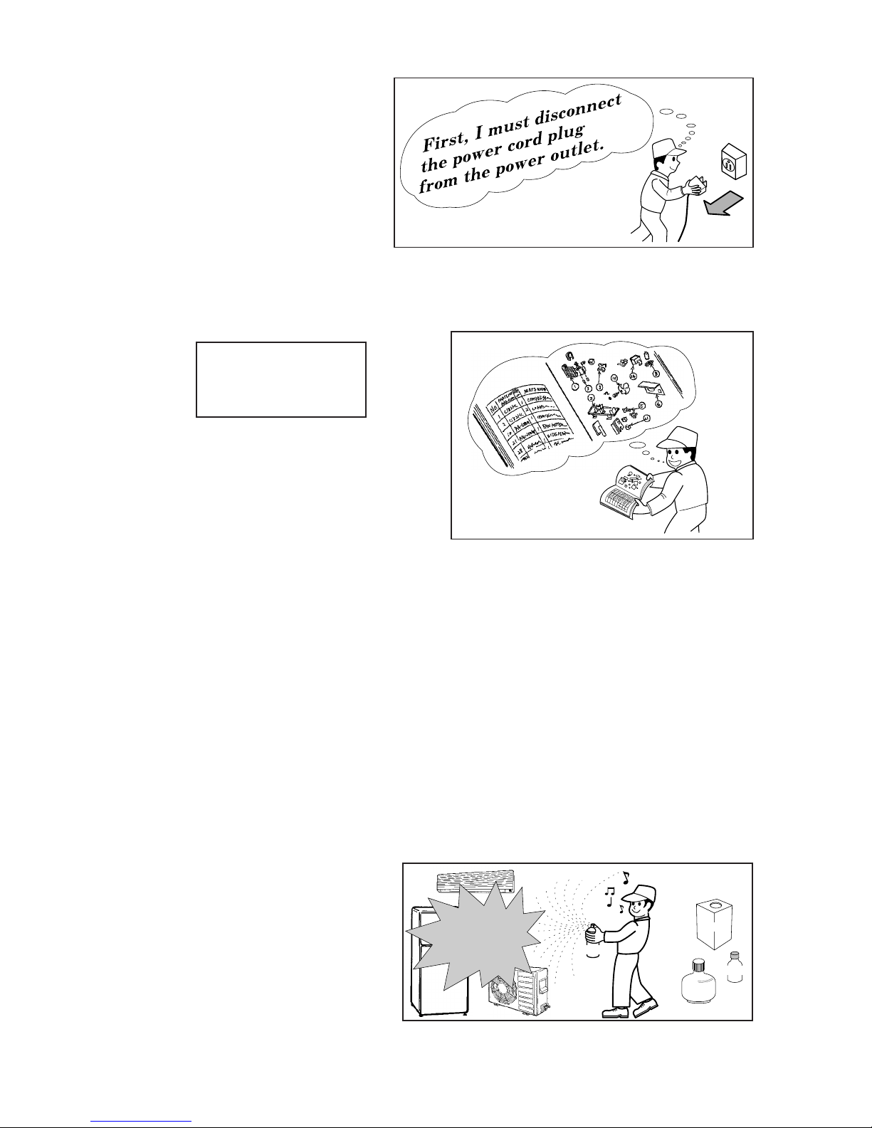
1. In order to disassemble and repair the
unit in question, be sure to disconnect the
power cord plug from the power outlet
before starting the work.
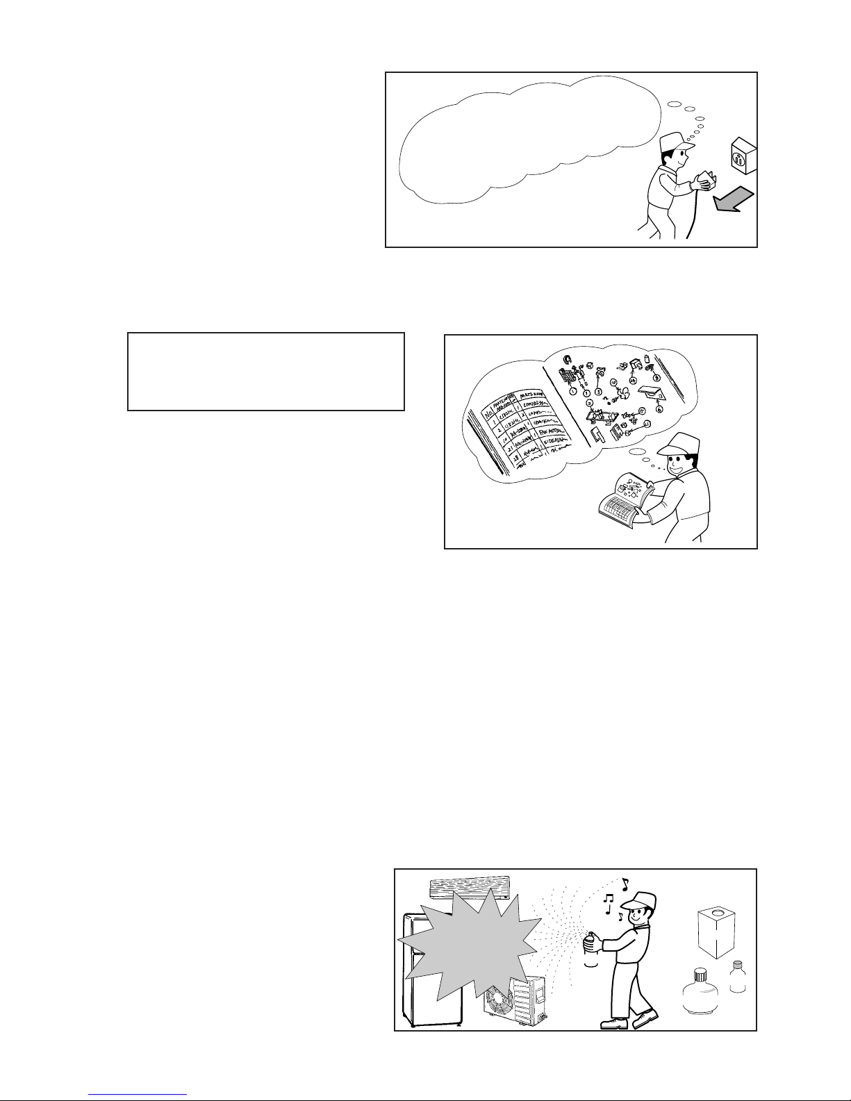
2. If it is necessary to replace any parts, they should be replaced with respective genuine parts for the unit,
and the replacement must be effected in correct manner according to the instructions in the Service
Manual of the unit.
3. After completion of repairs, the initial state should be
restored.
4. Lead wires should be connected and laid as in the
initial state.
5. Modification of the unit by the user himself should
absolutely be prohibited.
6. Tools and measuring instruments for use in repairs or inspection should be accurately calibrated in
advance.
7. In installing the unit having been repaired, be careful to prevent the occurrence of any accident such as
electrical shock, leak of current, or bodily injury due to the drop of any part.
8. To check the insulation of the unit, measure the insulation resistance between the power cord plug and
grounding terminal of the unit.
The insulation resistance should be 1MΩ or more as measured by a 500V DC megger.
9. The initial location of installation such as window, floor or the other should be checked for being safe
enough to support the repaired unit again.
If it is found not so strong and safe, the unit should be installed at the initial location after reinforced or
at a new location.
10. Any inflammable object must not be placed
about the location of installation.
11. Check the grounding to see whether it is
proper or not, and if it is found improper,
connect the grounding terminal to the earth.
Spray
gasoline
gasbombe
thinner
SAFETY DURING REPAIR WORK
If the contacts of electrical
parts are defective, replace
the electrical parts without
trying to repair them
1
2
3
4
5
DANGER
Page 3
– 1 –
1. Avant de procéder à une réparation, veillez
à couper l'alimentation électrique.
2. Les pièces de rechange doivent être des pièces d'origine et le remplacement des pièces doit être réalisé
conformément aux instructions figurant dans le manuel d'entretien.
3. Après achèvement des réparations, les conditions
initiales doivent être rétablies.
4. Après toute intervention, le raccordement et le
cheminement des câbles électriques doivent être
rétablis comme à l'origine.
5. Toute modification au niveau de l'installation ne peut être effectuée que par une personne compétente.
Toute intervention ou modification par l'utilisateur lui-même est par conséquent à proscrire.
6. Les outils et les appareils de mesure qui doivent être employés pour effectuer l'entretien auront été
préalablement réglés ou étalonnés comme il convient.
7. Lors de l'installation d'une unité ayant subi une réparation, veillez à éviter tout accident dû à une décharge
électrique ou la chute d'un objet.
8. Pour vérifier l'isolement de l'appareillage, mesurer la résistance entre le cordon d'alimentation et la borne
de masse. Cette résistance doit au moins être égale à 1MΩ lorsque la mesure est effectuée avec un
mégohmmètre de 500V CC.
9. Avant la fixation de l'unité réparée, vérifiez que les fixations d'origine peuvent supporter l'appareil. Si ces
fixations vous paraissent défectueuses, renforcez-les si possible et dans le cas contraire, l'unité doit être
fixée à un autre endroit.
10. L'emplacement de l'installation doit être
éloigné de toute matière inflammable.
11. La mise à la masse doit être soigneusement
contrôlée; en cas de défaut, la borne de
masse doit être mise à la terre.
Il faut d'abord que je coupe
I'alim
entation électrique.
Aérosol
Essence
Dilunt
Bonbonne de gaz
PRECAUTIONS RELATIVES A LA SECURITE PENDANT LES REPARATIONS
Si vous constatez que les contacts d'un
composant électrique sont défectueux,
remplacez le composant et ne tentez pas
de réparer les contacts.
DANGER
1
2
3
4
5
Page 4
– 2 –
WORKING STANDARDS FOR PREVENTING BREAKAGE OF SEMICONDUCTORS
1. Scope
The standards provide for items to be generally observed in carrying and handling semiconductors in
relative manufactures during maintenance and handling thereof. (They apply the same to handling of
abnormal goods such as rejected goods being returned.)
2. Object parts
(1) Microcomputer
(2) Integrated circuits (I.C.)
(3) Field effective transistor (F.E.T.)
(4) P.C. boards or the like to which the parts mentioned in (1) and (2) of this paragraph are equipped.
3. Items to be observed in handling
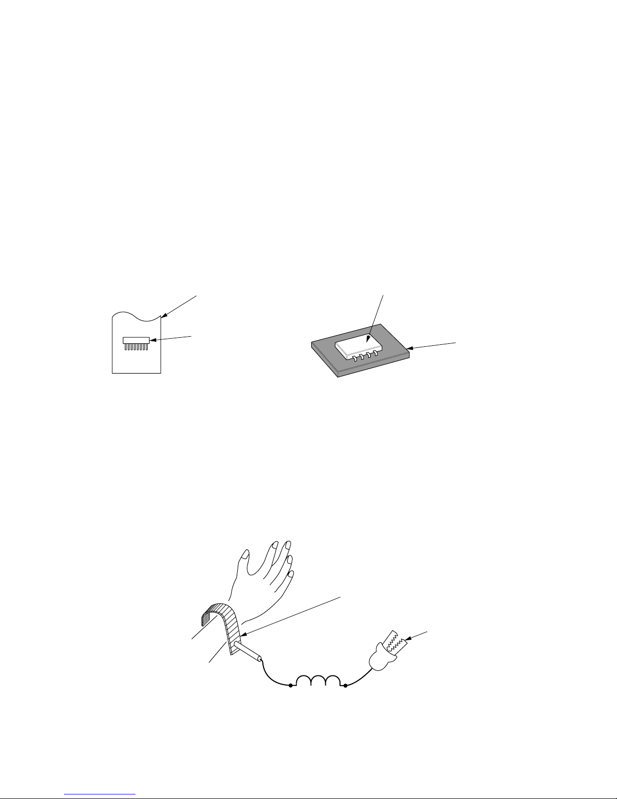
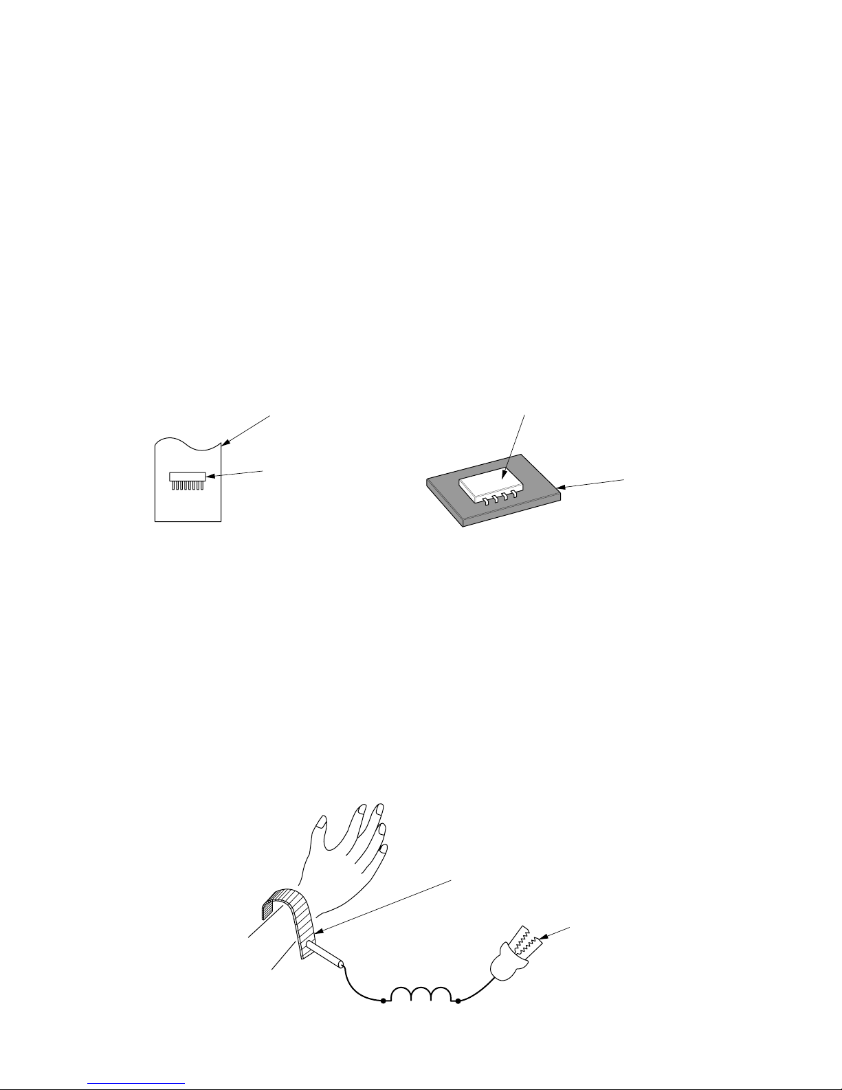
(1) Use a conductive container for carrying and storing of parts. (Even rejected goods should be handled in
the same way.)
(2) When any part is handled uncovered (in counting, packing and the like), the handling person must
always use himself as a body earth. (Make yourself a body earth by passing one M ohm earth
resistance through a ring or bracelet.)
(3) Be careful not to touch the parts with your clothing when you hold a part even if a body earth is
being taken.
(4) Be sure to place a part on a metal plate with grounding.
(5) Be careful not to fail to turn off power when you repair the printed circuit board. At the same time,
try to repair the printed circuit board on a grounded metal plate.
H
IT
A
C
H
I I
C
4
0
1
T
H
1
,
1
8
8
U
V
Fig. 1 Conductive container
A conductive polyvinyl bag
IC
IC
Conductive sponge
Fig. 2 Body earth
Body earth (Elimik conductive band)
Clip for connection with
a grounding wire
1MΩ
Page 5
– 3 –
PREVENTION DES DOMMAGES AUX SEMI-CONDUCTEURS
1. Champ d'application
Pour éviter d'endommager les semi-conducteurs utilisés dans les unités, lors de chaque intervention
d'entretien ou de réparation, vous devez observer des précautions spéciales. Les mêmes précautions
doivent être prises lors de la manipulation d'organes défectueux qui doivent être retournés en usine.
2. Pièces détachées de l'appareillage.
(1) Microprocesseur
(2) Circuits intégrés (C.I.)
(3) Transistor à effet de champ (T.E.C)
(4) Circuits imprimés sur lesquels se trouvent implantés les composants (1) et (2).
3. Précautions de manipulation
(1) Pour transporter ou stocker un semi-conducteur, placez-le dans un emballage conducteur. Procéder de
même avec un composant défectueux.
(2) Lorsque vous maniqulez des composants qui ne sont pas protégés (par exemple pour les compter ou
les emballer), vous devez veiller à ce que votre corps soit électriquement relié à la terre. Pour cela,
portez un bracelet conducteur. Reliez le bracelet à une résistance de 1MΩ et celle-ci à la terre par
l'intermédiaire d'un conducteur.
(3) Veillez en outre à ce que vos vêtements ne viennent jamais en contact avec le composant même si
votre corps est relié à la terre.
(4) Déposez le composant sur une surface métallique correctement mise à la terre.
(5) Sous aucun prétexte, n'omettez de couper l'alimentation avant de procéder à une réparation sur un
circuit imprimé. Par ailleurs, l'intervention sur le circuit imprimé doit se faire alors que celui-ci repose
sur une surface métallique mise à la masse.
H
IT
A
C
H
I IC
4
0
1
T
H
1
,
1
8
8
U
V
Fig. 1 Emballage conducteur
Sac en polyvinyle
conducteur
C.I.
C.I.
Eponge
conductrice
Fig. 2 Mise à la terre du corps
Bracelet de mise à la terre du corps
(Bande conductrice Elimik)
Pince de connexion avec
fil de mise à la terre
1MΩ
Page 6
– 4 –
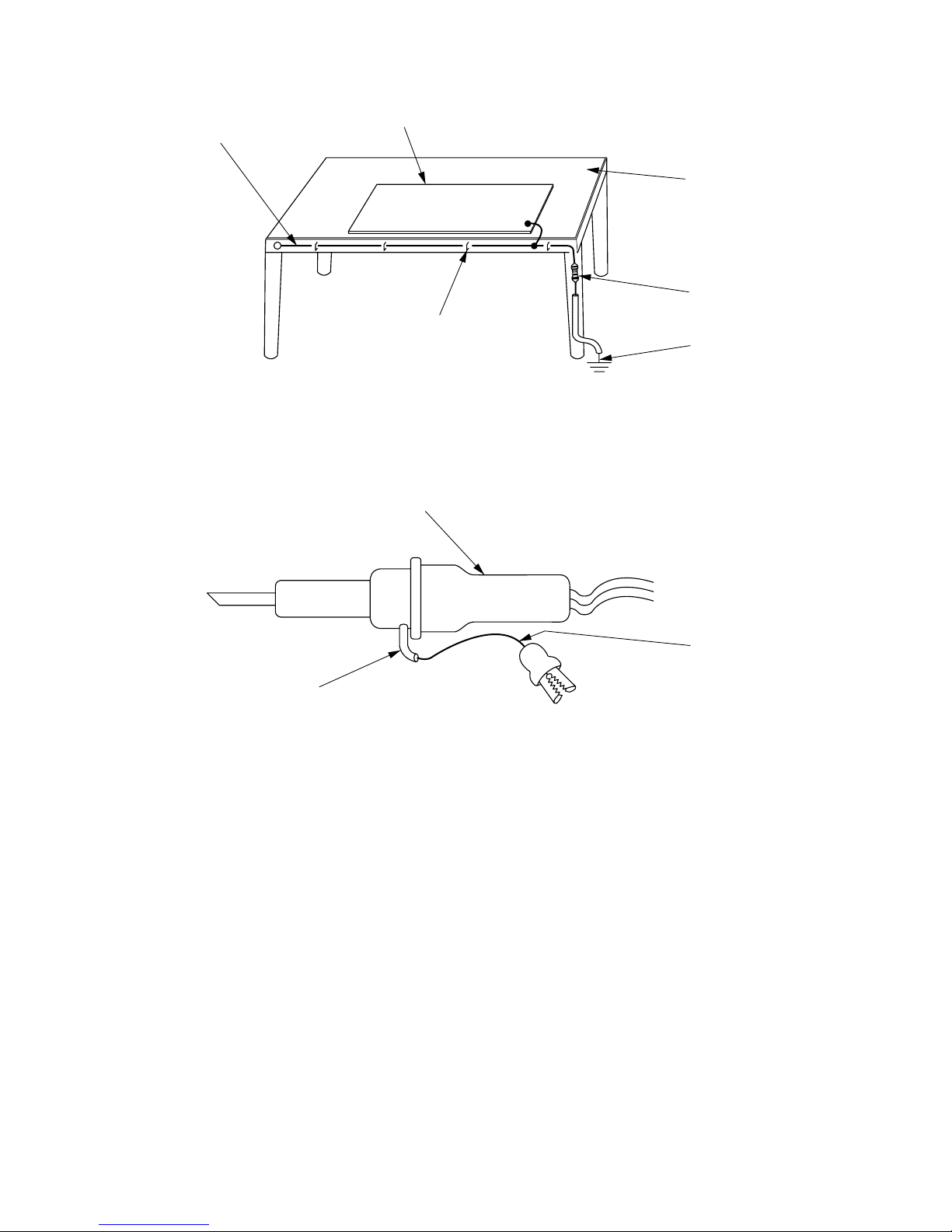
(6) Use a three wire type soldering iron including a grounding wire.
Fig.4 Grounding a solder iron
Use a high insulation mode (100V, 10MΩ or higher) when ordinary iron is to be used.
(7) In checking circuits for maintenance, inspection, or some others, be careful not to have the test probes
of the measuring instrument shortcircuit a load circuit or the like.
Bare copper wire (for body earth)
Metal plate (of Al. stainless steel, etc.)
Working table
Resistor 1MΩ(1/2W)
Earth wirte
Staple
Fig.3 Grounding of the working table
soldering iron
Grounding wire
Screw stop at the screwed
part using a rag plate
Page 7
– 5 –
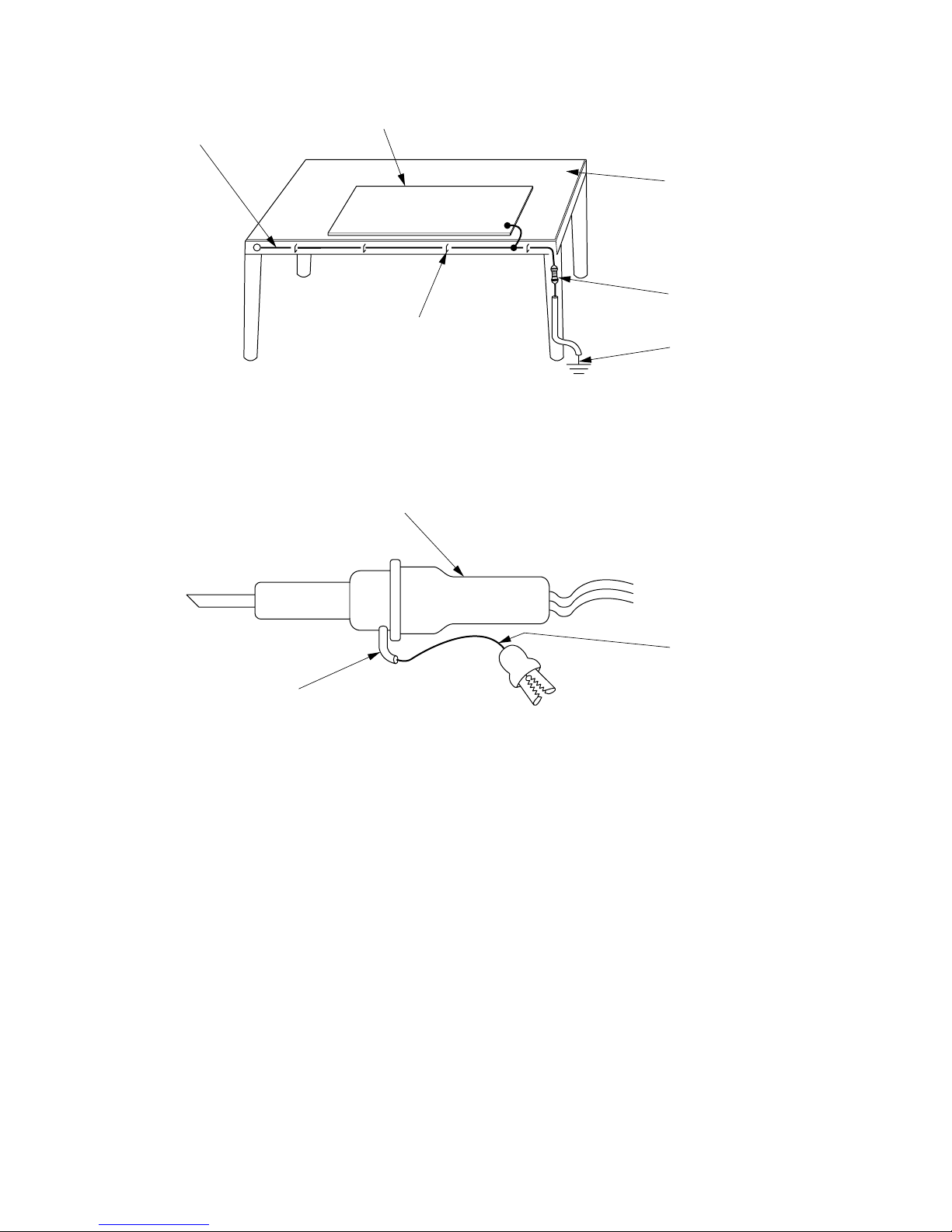
(6) Le fer à souder doit être alimenté par un câble à trois conducteurs (dont un pour la mise à la terre).
Fig.4 Mise à la terre d'un fer à souder
Vous pouvez également utiliser un fer à souder ordinaire dans la mesure où il est parfaitement
isolé (au moins 10MΩ sous 100V).
(7) Pendant le contrôle des circuits au cours des opérations d'entretien ou d'inspection, évitez à tout prix la
mise en court-circuit de la charge par les pointes de contact de l'appareil de mesure.
Fil de cuivre nu
(pour mise à la
terre du corps)
Surface métallique (aluminium, acier inoxydable, etc.)
Plan de travail
Résistance de
1MΩ (1/2W)
Câble de masse
Agrafe
Fig.3 Mise à la terre d'un plan de travail
fer à souder
Câble de masse
Poser ici une rondelle éventail et la visser
Page 8

– 6 –
1. In quiet operation or stopping the running, its heard slight flowing noise of
refrigerant in the refrigerating cycle occasionally, but this noise is not abnormal
for the operation.
2. When it thunders near by, it is recommend to stop the operation and to
disconnect the power cord plug from the power outlet for safety.
3. The room air conditioner dose not start automaticaly after recovery of the
electric power failure for preventing fuse blowing. Re-press START / STOP
button after 3 minutes from when unit stopped.
4. If the room air conditioner is stopped by adjusting thermostat, or missoperation,
and re-start in a moment, there is occasion that the cooling and heating
operation does not start for 3 minutes, it is not abnormal and this is the result
of the operation of IC delay circuit. This IC delay circuit ensures that there is
no danger of blowing fuse or damaging parts even if operation is restarted
accidentally.
5. This room air conditioner should not be used at the cooling operation when the
outside temperature is below –10˚C (14˚F).
6. This room air conditioner (the reverse cycle) should not be used when the
outside temperature is below –15˚C (5˚F).
If the reverse cycle is used under this condition, the outside heat exchanger is
frosted and efficiency falls.
7. When the outside heat exchanger is frosted, the front is melted by operating
the hot gas system, it is not trouble that at this time fan stops and the vapour
may rise from the outside heat exchanger.
CAUTION
Page 9

– 7 –
1. Dans certaines conditions et pendant un arrêt de fonctionnement, on peut
parfois entendre le bruit du réfrigérant circulant dans les canalisations; ce bruit
n'a rien d'anormal.
2. Pour des raisons de sécurité, il est conseillé, pendant un orage, d'arrêter le
fonctionnement du système en coupant l'alimentation électrique.
3. Pour éviter que le fusible ne fonde, le climatiseur ne démarre pas
automatiquement après une panne de secteur. La remise en marche suppose
une pression sur la touche START / STOP après un délai d'au moins 3 minutes
suivant l'arrêt.
4. Si le climatiseur est arrêté à la suite d'un réglage de thermostat, ou à cause
d'une fausse manoeuvre et qu'il est remis en route, il se peut que la
réfrigération ou le chauffage ne reprenne qu'après 3 minutes. Ce phénomène
est normal et dû à un relais temporisé. Ce relais temporisé a pour rôle
d'éviter que le fusible ne fonde ou que des composants ne soient
endommagés par une remise en service accidentelle.
5. Ce climatiseur ne doit pas être utilisé pour réfrigérer une pièce lorsque la
température extérieure est inférieure à –10˚C (14˚F).
6. Ce climatiseur ne doit pas être utilisé lorsque la température extérieure est
inférieure à –15˚C (5˚F).
En effet, dans ce cas, l'échangeur de chaleur extérieur gèle et le rendement
chute considérablement.
7. Quand l'échangeur de chaleur extérieur est givré, les gaz chauds peuvent
entraîner une vaporisation de l'eau accumulée sur la face avant. Ce n'est pas
un problème si à ce moment-là le ventilateur s'arrête et il se peut que de la
vapeur se dégage de l'échangeur de chaleur extérieur.
ATTENTION
Page 10
– 8 –
MODEL
FAN MOTOR
FAN MOTOR CAPACITOR
FAN MOTOR PROTECTOR
COMPRESSOR
OVER HEAT PROTECTOR
OVERLOAD RELAY
FUSE (for MICRO COMPUTER)
POWER RELAY, STICK RELAY
POWER SWITCH
TEMPORARY SWITCH
SERVICE SWITCH
TRANSFORMER
VARISTOR
NOISE SUPPRESSOR
THERMOSTAT
REFRIGERANT CHARGING VOLUME
(R410A)
CHARGE EN RÉFRIGÉRANT
(R410A)
UNIT UNITÉ
PIPES
CANALISATIONS
(MAX. 30m)
SPECIFICATIONS CARACTERISTIQUES GENERALES
MODÈLE
MOTEUR DE VENTILATEUR
COMPRESSEUR
RELAIS DE SURCHARGE
INTERRUPTEUR D'ALIMENTATION
INTERRUPTEUR AUXILIAIRE
INTERRUPTEUR DE SERVICE
TRANSFORMATEUR
VARISTANCE
ANTIPARASITAGE
THERMOSTAT
CONDENSATEUR DE MOTEUR
DE VENTILATEUR
PROTECTION DU MOTEUR
DE VENTILATEUR
PROTECTION CONTRE LES
SURCHAUFFES
FUSIBLE
(pour MICROPROCESSEUR)
RELAIS DE PUISSANCE,
RELAIS AUTOEXCITE
REMOTE CONTROL SWITCH (LIQUID CRYSTAL)
INTERRUPTEUR DE TÉLÉCOMMANDE (CRISTAUX LIQUIDES)
YES (RAR-3U4)
OUI (RAR-3U4)
NO
NON
FUSE CAPACITY
CALIBRE DE FUSIBLE
RAS-50WX8, RAS-D18EX3
25W (DC35V)
NO NON
NO NON
NO NON
NO NON
YES OUI
NO NON
NO NON
NO NON
NO NON
YES (IC) OUI (IC)
RAC-50WX8, RAC-D18EX3
47W (DC380V)
EU1013E2
YES OUI
YES OUI
3A
G4A
NO NON
YES OUI
NO NON
450NR
NO NON
NO NON
WITHOUT REFRIGERANT BECAUSE COUPLING
IS FLARE TYPE.
SANS RÉFRIGÉRANT EN RAISON DU
RACCORDEMENT FLARE.
A INRUSH - WITH STAND TYPE
A RETARDE-AVEC STAND TYPE
NO NON
NO NON
NO NON
1,350g
Page 11
– 9 –
HOW TO USE
MODEL RAS-50WX8 / RAC-50WX8, RAS-D18EX3 / RAC-D18EX3
– 3 –
ENGLISH
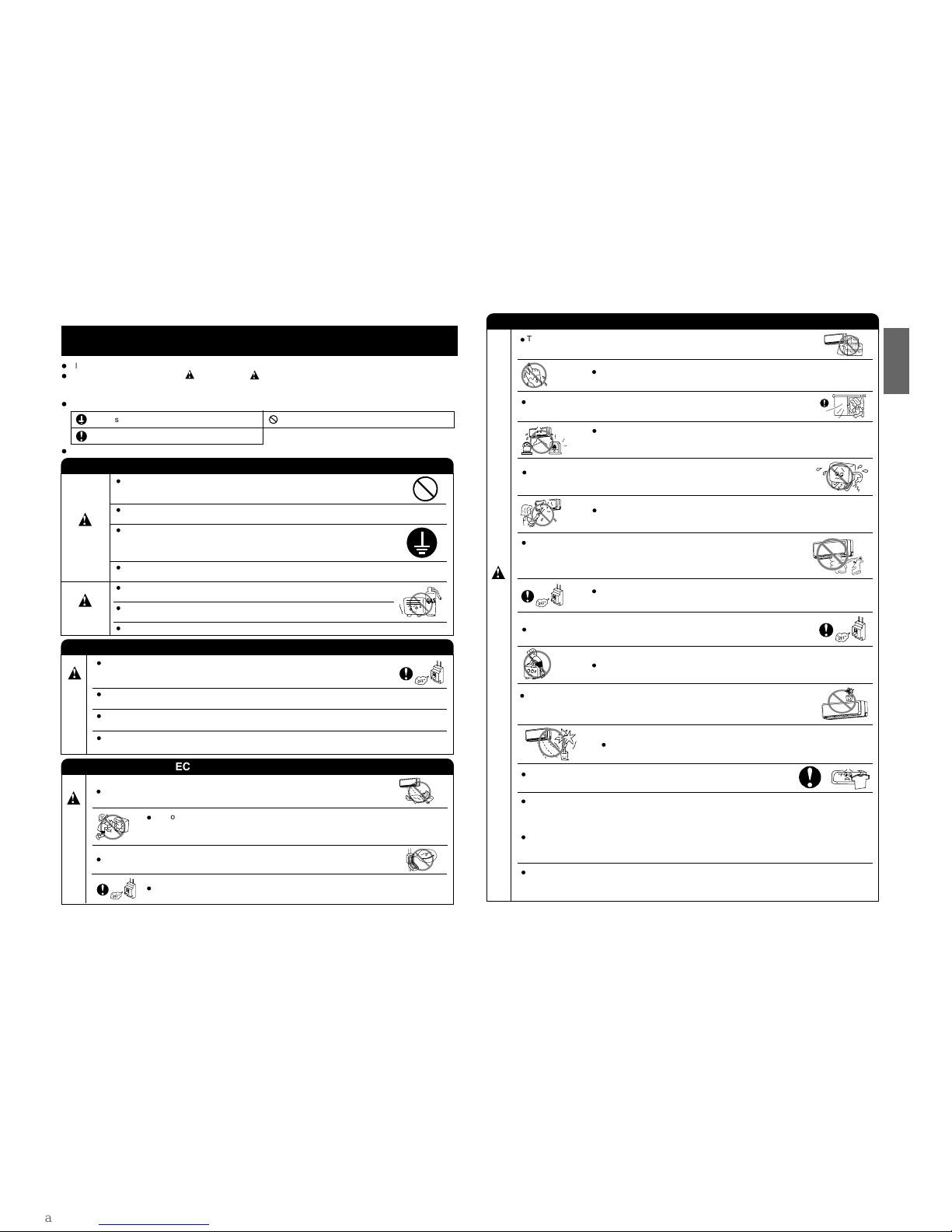
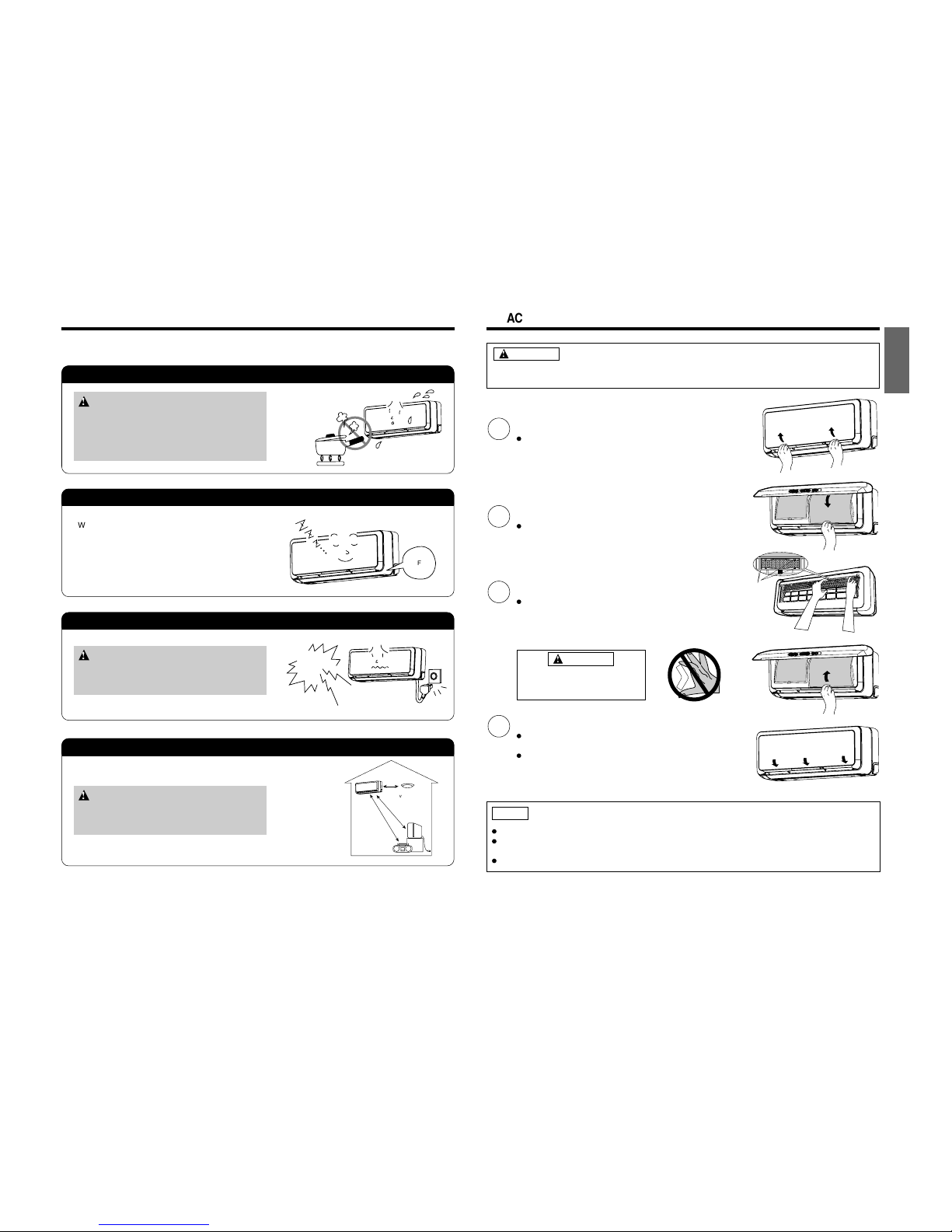
PRECAUTIONS DURING OPERATION
Do not attempt to operate the unit with wet hands, this could cause fatal
accident.
When operating the unit with burning equipments, regularly ventilate the
room to avoid oxygen insufficiency.
Do not direct the cool air coming out from the air-conditioner panel to face
household heating apparatus as this may affect the working of apparatus
such as the electric kettle, oven etc.
Do not use any aerosol or hair sprays near the indoor unit. This chemical
can adhere on heat exchanger fin and blocked the evaporation water flow
to drain pan. The water will drop on tangential fan and cause water splashing
out from indoor unit.
Please ensure that outdoor mounting frame is always stable, firm and
without defect. If not, the outdoor unit may collapse and cause danger.
Do not splash or direct water to the body of the unit when cleaning it as this
may cause short circuit.
When operating the unit with the door and windows opened, (the room humidity is always above
80%) and with the air deflector facing down or moving automatically for a long period of time,
water will condense on the air deflector and drips down occasionally. This will wet your furniture.
Therefore, do not operate under such condition for a long time.
If the amount of heat in the room is above the cooling or heating capability of the unit (for
example: more people entering the room, using heating equipments and etc.), the preset room
temperature cannot be achieved.
This appliance is not to be used by children or persons with reduced physical, sensory or mental
capabilities, or lack of experience and knowledge, unless they have been given supervision or
instruction. Children must be supervised not to play with the appliance.
Do not climb on the outdoor unit or put objects on it.
Please switch off the unit and turn off the circuit breaker during cleaning, the
high-speed fan inside the unit may cause danger.
Turn off the circuit breaker if the unit is not to be operated for a long period.
C
A
U
T
I
O
N
The product shall be operated under the manufacturer specification and
not for any other intended use.
Do not put water container (like vase) on the indoor unit to avoid water
dripping into the unit. Dripping water will damage the insulator inside the unit
and causes short-circuit.
Do not place plants directly under the air flow as it is bad for the plants.
Do not hang any laundry onto the moveable panels.
The moveable panels may get dislodged and may cause serious injuries.
SAFETY PRECAUTION
– 2 –
Please read the “Safety Precaution” carefully before operating the unit to ensure correct usage of the unit.
Pay special attention to signs of “ Warning” and “ Caution”. The “Warning” section contains matters which,
if not observed strictly, may cause death or serious injury. The “Caution” section contains matters which may
result in serious consequences if not observed properly. Please observe all instructions strictly to ensure safety.
The sign indicate the following meanings.
Please keep this manual after reading.
WARNING
PRECAUTIONS DURING INSTALLATION
Do not reconstruct the unit.
Water leakage, fault, short circuit or fire may occur if you reconstruct the unit by
yourself.
Please ask your sales agent or qualified technician for the installation of your unit.
Water leakage, short circuit or fire may occur if you install the unit by yourself.
Please use earth line.
Do not place the earth line near water or gas pipes, lightning-conductor, or the
earth line of telephone. Improper installation of earth line may cause electric
shock.
Be sure to use the specified piping set for R410A. Otherwise, this may result in
broken copper pipes or faults.
A circuit breaker should be installed depending on the mounting site of the unit.
Without a circuit breaker, the danger of electric shock exists.
Do not install near location where there is flammable gas. The outdoor unit may
catch fire if flammable gas leaks around it.
Please ensure smooth flow of water when installing the drain hose.
CAUTION
PRECAUTIONS DURING OPERATION
Avoid an extended period of direct air flow for your health.
W
A
R
N
I
N
G
Do not insert a finger, a rod or other objects into the air outlet or inlet. As the fan
is rotating at a high speed, it will cause injury. Before cleaning, be sure to stop the
operation and turn the breaker OFF.
During thunder storm, disconnect and turn off the circuit breaker.
Do not use any conductor as fuse wire, this could cause fatal accident.
Make sure to connect earth line.
Indicates the instructions that must be followed.
The sign in the figure indicates prohibition.
PRECAUTIONS DURING SHIFTING OR MAINTENANCE
Should abnormal situation arises (like burning smell), please stop operating the unit
and turn off the circuit breaker. Contact your agent. Fault, short circuit or fire may
occur if you continue to operate the unit under abnormal situation.
Please contact your agent for maintenance. Improper self maintenance may cause
electric shock and fire.
Please contact your agent if you need to remove and reinstall the unit. Electric
shock or fire may occur if you remove and reinstall the unit yourself improperly.
If the supply cord is damaged, it must be replaced by the special cord obtainable
at authorized service/parts centers.
W
A
R
N
I
N
G
Page 12
– 10 –
ENGLISH
– 2 –
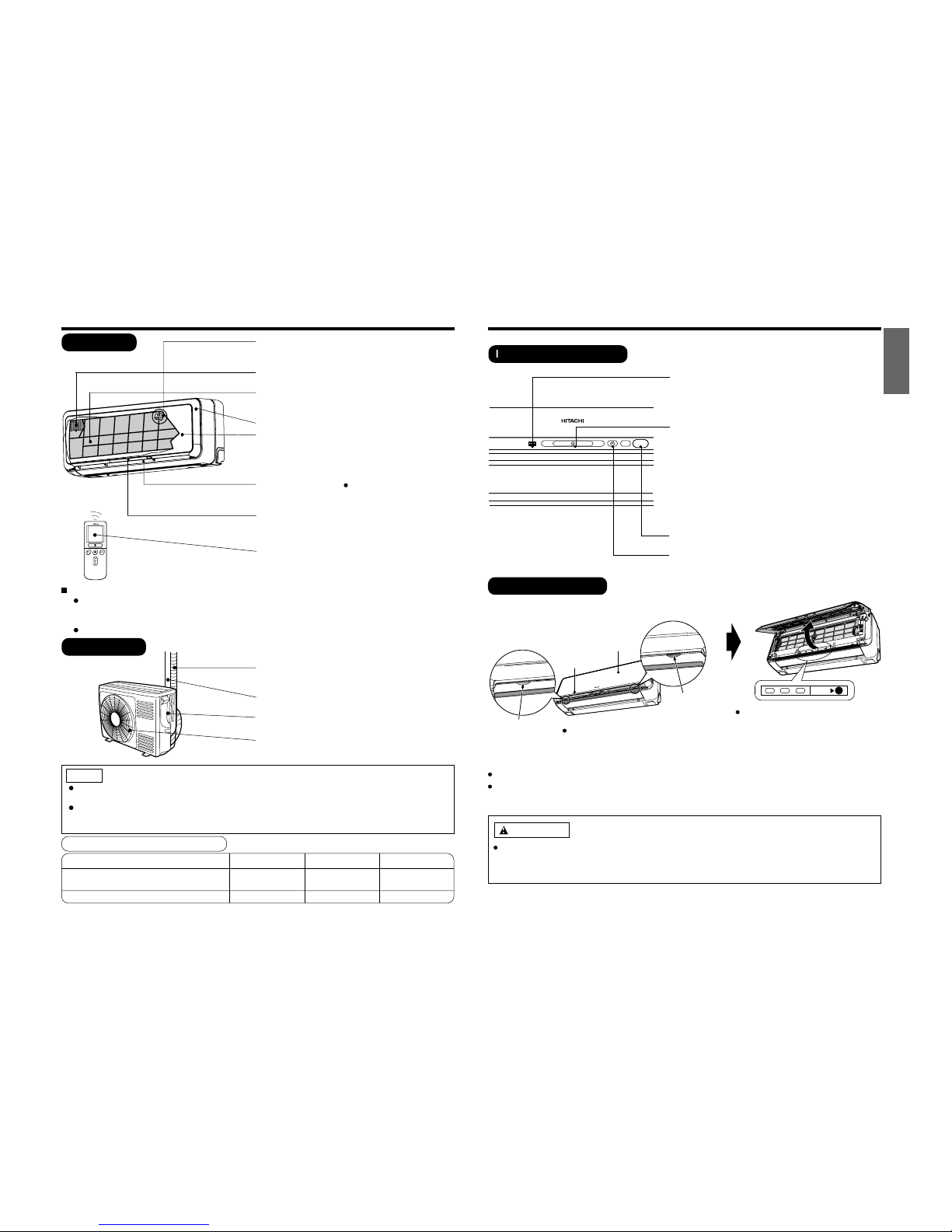
Electrical Dust Collector
Negative ions are generated to capture all air-borne
dirt and dust particle.
Air cleansing filter
(Refer Instruction manual)
Air filter
To prevent dust from coming into the indoor unit.
(Refer Instruction manual)
Front panel
Moveable panel
It will be on when the air conditioner is operated and
off when the air conditioner is not in operation.
(Occasionally it may not be on during the operating
mode)
Horizontal deflector
Vertical deflector
(Air Outlet)
(Refer Instruction manual)
Indoor unit indicators
Light indicator showing the operating condition.
(Refer page 3)
WIDTH (mm)
795
MODEL
HEIGHT (mm)
295
DEPTH (mm)
198
Air cleansing filters are washable and can be use in 1 year time. Type number for this air cleansing
filter is <SPX-CFH20>. Please use this number for ordering when you want to renew it.
Air cleansing filter should be cleaned every month or sooner if noticeable loading occurs. When
used overtime, it may loose its deodorizing function. For maximum performance, it is recommended
to replace it every 1 year depending on application requirements.
NOTE
Moveable Panel
It will open up automatically when the air conditioner is in operation to allow a large quantity of air
flowing through as a sort of heat exchange; and it will close up automatically when the air conditioner
stopped operating. Avoid physical adjustments as it may damage the panels’ mechanisms.
Please do not touch the moving panels during operations as they may pinch your fingers.
RAS-50WX8(W) / RAS-50WX8(B)
RAS-D18EX3(W) / RAS-D18EX3(B)
Remote controller
Send out operation signal to the indoor unit. So as
to operate the whole unit.
(Refer Instruction manual)
RAC-50WX8 / RAC-D18EX3
600 650 299
Drain pipe
Condensed water drain to outside.
Connecting cord and insulation pipe for piping
Air inlet (Back and Left side)
Air outlet
NAMES AND FUNCTIONS OF EACH PART
INDOOR UNIT
OUTDOOR UNIT
MODEL NAME AND DIMENSIONS
– 3 –
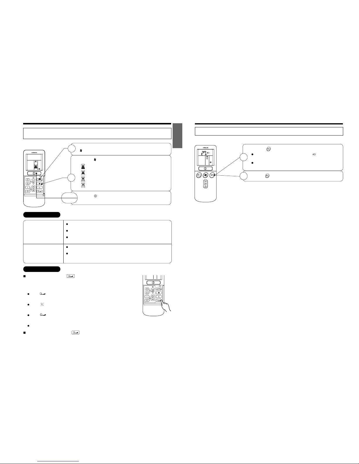
FILTER LAMP
When the device is operated for a total of about 200
hours, the FILTER lamp lights to indicate that it is time
to clean the filter.
OPERATION LAMP
This lamp lights during operation.
The OPERATION LAMP flashes in the following cases
during heating.
(1) During preheating
For about 2–3 minutes after starting up.
(2) During defrosting
Defrosting will be performed about once every one
hour when frost forms on the heat exchanger of the
outdoor unit, for 5–10 minutes each time.
SIGNAL RECEIVING PORT
TIMER LAMP
This lamp lights when the timer is working.
TEMPORARY SWITCH
Use this switch to star t and stop when the remote controller does not work.
By pressing the temporary switch, the operation is done in previously set operation mode.
When the operation is done using the temporary switch after the power source is turned off and turn on
again, the operation is done in automatic mode.
T
E
M
P
O
R
A
R
Y
S
W
I
T
C
H
TEMPORARY
SWITCH
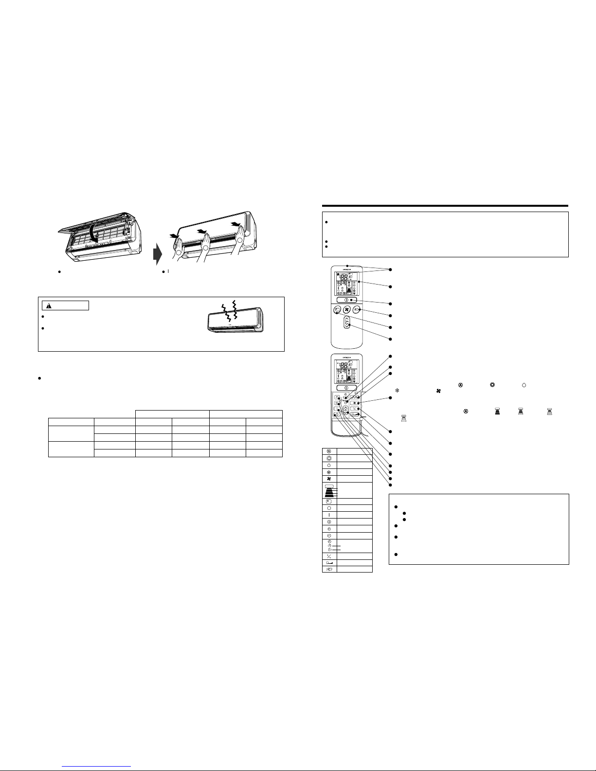
Front panel
Moveable panel
Hand grip point
Lift the front panel
Hand grip point
Do not hold the moveable panel
when the front panel is in either
opened/closed position.
1. Opening up the front panel
Never try to force open/close the moveable panel manually.
Manually opening or closing the moveable panel may cause breakdowns (The moveable panel will
automatically close or open when the power supply is switched on or switched off and whenever the unit
is in operations or has stopped operating.
CAUTION
INDOOR UNIT INDICATORS
OPERATION INDICATOR
Page 13
– 11 –
Minimum Maximum Minimum Maximum
Indoor Dry bulb °C21 32 20 27
Wet bulb °C15 23 12 19
Outdoor Dry bulb °C21 43 2 21
Wet bulb °C15 26 1 15
Note
Avoid to use the room air conditioner for cooling operation when the outside temperature is below
-10°C (14°F).
The recommended maximum and minimum operating temperatures of the hot and cold sides
should be as below:
Cooling Heating
Pull toward the down direction.
1
2
1
When front panel is shaky, there is a possibility panel coming off and
falling down.
Do not apply extra force on the front panel when it is opened up in
the upright position.
Also frequent removal of the front panel from the front cover may
cause damage.
Initially press the left and the right sides of the
front panel and finally press the central portion
until you hear a clicking sound.
2. Closing the Front Panel
CAUTION
– 4 –
– 4 –
SILENT
LOW
MED
HI
AUTO
HEAT
DEHUMIDIFY
COOL
FA N
FA N SPEED
SLEEPING
STOP (CANCEL)
START (RESERVE)
START/STOP
TIME
TIMER SET
TIMER SELECTOR
ON TIMER
OFF TIMER
AUT
EXTENDED AIRFLOW
AIR PURIFIER
O SWING
REMOTE CONTROLLER
This controls the operation of the indoor unit. The range of control is about 7 meters. If indoor lighting is controlled
electronically, the range of control may be shorter.
This unit can be fixed on a wall using the fixture provided. Before fixing it, make sure the indoor unit can be controlled
from the remote controller.
Handle the remote controller with care. Dropping it or getting it wet may compromise its signal transmission capability.
After new batteries are inserted into the remote controller, the unit will initially require approximately 10 seconds to
respond to commands and operate.
Signal emitting window/transmission sign
Point this window toward the indoor unit when controlling it.
The transmission sign blinks when a signal is sent.
Display
This indicates the room temperature selected, current time, timer status, function
and intensity of circulation selected.
START/STOP button
Press this button to start operation. Press it again to stop operation.
AIR PURIFIER button
Use this button to start air purifying function.
SLEEP button
Use this button to set the sleep timer.
TEMPERATURE buttons
Use these buttons to raise or lower the temperature setting. (Keep pressed, and
the value will change more quickly.)
TIME button
Use this button to set and check the time and date.
RESET buttons
FUNCTION selector
Use this button to select the operating mode. Every time you press it,
the mode will change from (AUTO) to (HEAT) to (DEHUMIDIFY) to
(COOL) and to (FAN) cyclically.
FAN SPEED selector
This determines the fan speed. Every time you press this button, the intensity
of circulation will change from (AUTO) to (HI) to (MED) to (LOW)
to (SILENT) (This button allows selecting the optimal or preferred fan speed
for each operation mode).
AUTO SWING button
Controls the angle of the horizontal air deflector.
EXTENDED AIRFLOW button
Use this button to deliver faster and more comfortable air conditioning.A
TIMER control
Use this button to set the timer.
OFF-TIMER button Select the tur n OFF time.
ON-TIMER button Select the turn ON time.
RESERVE button Time setting reservation.
CANCEL button Cancel time reservation.
Precautions for Use
Do not put the remote controller in the following places.
Under direct sunlight.
In the vicinity of a heater.
Handle the remote controller carefully. Do not drop it on the floor, and protect it
from water.
Once the outdoor unit stops, it will not restart for about 3 minutes (unless you turn
the power switch off and on or unplug the power cord and plug it in again).
This is to protect the device and does not indicate a failure.
If you press the FUNCTION selector button during operation, the device may stop
for about 3 minutes for protection.
NAMES AND FUNCTIONS OF REMOTE CONTROL UNIT
Page 14
– 12 –
– 5 –
The device will automatically determine the mode of operation, HEAT, COOL or DEHUMIDIFY depending on the current room
temperature. The selected mode of operation will change when the room temperature varies. However the mode of operation will
not change when indoor unit connected to multi type outdoor unit.
If there is a power failure, operation will be automatically restarted when the power is resumed with previous operation mode
and airflow direction.
(As the operation is not stopped by remote controller.)
If you intend not to continue the operation when the power is resumed, switch off the power supply.
When you switch on the circuit breaker, the operation will be automatically restarted with previous operation mode and airflow
direction.
Note: 1. If you do not require Auto Restart Control, please consult your sales agent or OFF by remote control.
2. Auto Restart Control is not available when Timer or Sleep Timer mode is set.
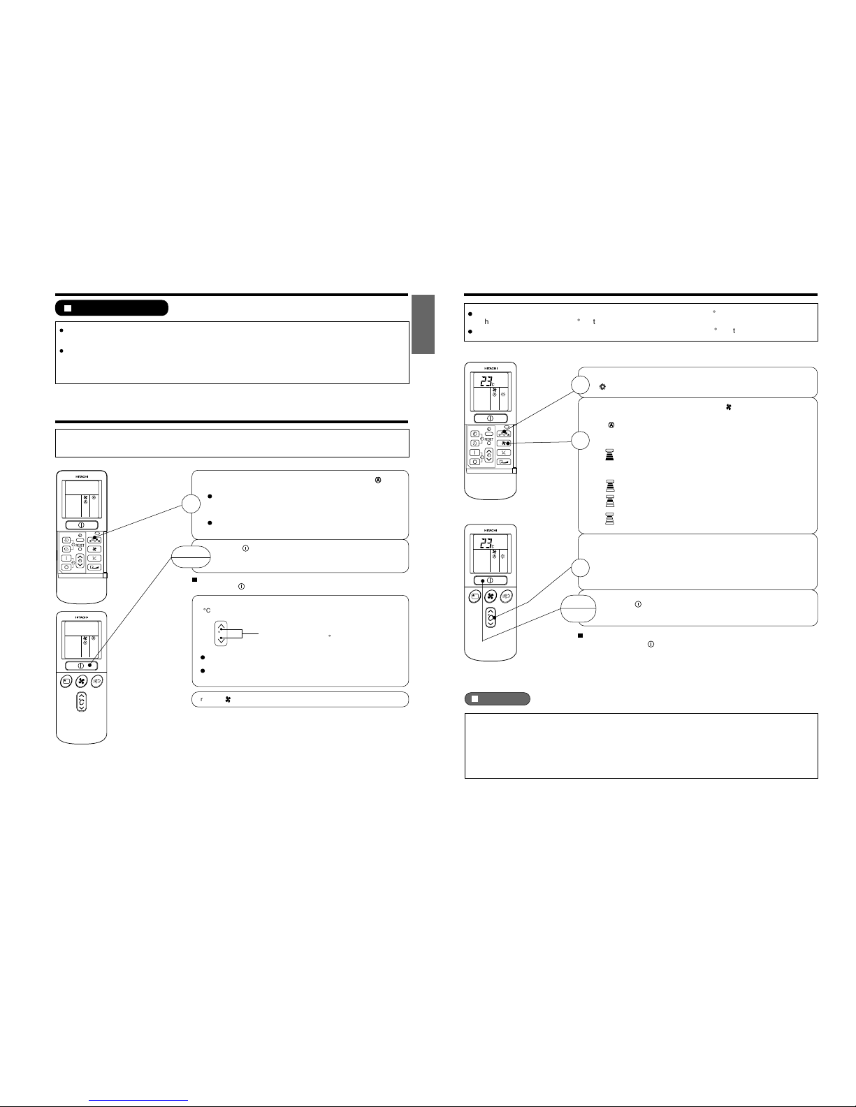
As the settings are stored in memory in the remote controller, you only have
to press the (START/STOP) button next time.
Press the FUNCTION selector so that the display indicates the (AUTO)
mode of operation.
When AUTO has been selected, the device will automatically determine
the mode of operation, HEAT, COOL or DEHUMIDIFY depending on
the current room temperature. However the mode of operation will
not change when indoor unit connected to multi type outdoor unit.
If the mode automatically selected by the unit is not satisfactory,
manually change the mode setting (heat, dehumidify, cool or fan).
Press the (START/STOP) button.
Operation starts with a beep.
Press the button again to stop operation.
You can raise or lower the temperature setting as necessary by maximum of
3°C.
Press the temperature button and the temperature
setting will change by 1°C each time.
The preset temperature and the actual room temperature may vary
somewhat depending on conditions.
The display does not indicate the preset temperature in the AUTO mode.
If you change the setting, the indoor unit will produce a beep.
1
START
STOP
°
C
Press the (FAN SPEED) button, AUTO, LOW and SILENT is available.
VARIOUS FUNCTIONS
Auto Restart Control
AUTOMATIC OPERATION
ENGLISH
– 6 –
Use the device for heating when the outdoor temperature is under 21°C.
When it is too warm (over 21°C), the heating function may not work in order to protect the device.
In order to keep reliability of the device, please use this device above -15°C of the outdoor temperature.
Press the FUNCTION selector so that the display indicates
(HEAT).
Set the desired FAN SPEED with the (FAN SPEED) button
(the display indicates the setting).
(AUTO) : The fan speed changes automatically
according to the temperature of the air which
blows out.
(HI) : Economical as the room will become warm
quickly.
But you may feel a chill at the beginning.
(MED) : Fan speed slow.
(LOW) : Fan speed slower.
(SILENT) : Fan speed ultra slower.
Set the desired room temperature with the TEMPERATURE
buttons (the display indicates the setting).
The temperature setting and the actual room temperature may
vary somewhat depending on conditions.
Press the (START/STOP) button. Heating operation starts
with a beep. Press the button again to stop operation.
As the settings are stored in memory in the remote controller, you only
have to press the (START/STOP) button next time.
1
2
3
START
STOP
Defrosting
Defrosting will be performed about once an hour when frost forms on the heat exchange of the outdoor
unit, for 5~10 minutes each time.
During defrosting operation, the operation lamp blinks in cycle of 3 seconds on and 0.5 second off.
The maximum time for defrosting is 20 minutes.
However, if it is connected to multi type outdoor unit, the maximum time for defrosting is 15 minutes.
(If the piping length used is longer than usual, frost will likely to form.)
HEATING OPERATION
Page 15
– 13 –
– 7 –
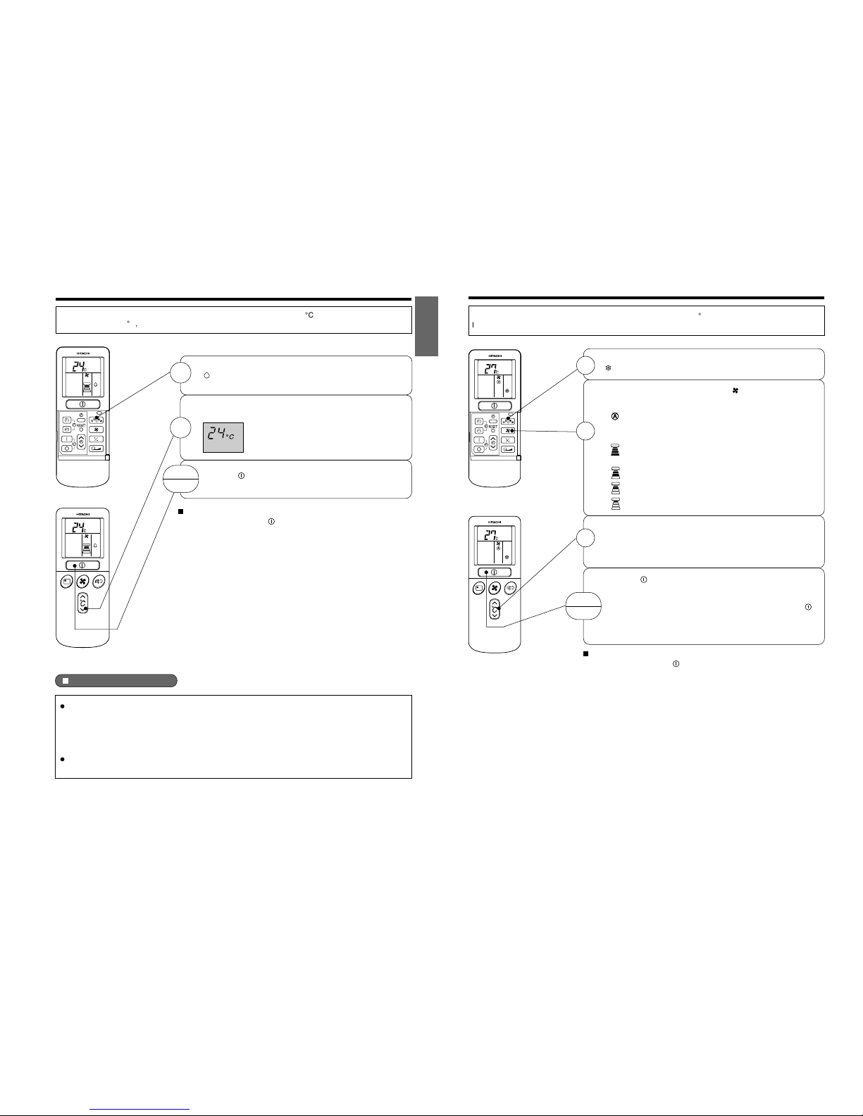
Dehumidifying Function
When the room temperature is higher than the temperature setting: The device will dehumidify the
room, reducing the room temperature to the preset level.
When the room temperature is lower than the temperature setting: Dehumidifying will be performed
at the temperature setting slightly lower than the current room temperature, regardless of the temperature
setting. The function will stop (the indoor unit will stop emitting air) as soon as the room temperature
becomes lower than the setting temperature.
The preset room temperature may not be reached depending on the number of people present in the
room or other room conditions.
Use the device for dehumidifying when the room temperature is over 16°C.
When it is under 15°C, the dehumidifying function will not work.
Set the desired room temperature with the TEMPERATURE
button (the display indicates the setting).
The range of 20-26˚C is recommended as
the room temperature for dehumidifying.
Press the (START/STOP) button. Dehumidifying operation
starts with a beep. Press the button again to stop operation.
2
As the settings are stored in memory in the remote controller, you
only have to press the
(START/STOP) button next time.
START
STOP
Press the FUNCTION selector so that the display indicates
(DEHUMIDIFY).
The FAN SPEED is set at LOW or SILENT.
1
DEHUMIDIFYING OPERATION
ENGLISH
– 8 –
Use the device for cooling when the outdoor temperature is 21~43°C.
If in doors humidity is very high (80%), some dew may form on the air outlet grille of the indoor unit.
Press the FUNCTION selector so that the display indicates
(COOL).
Set the desired FAN SPEED with the
(FAN SPEED) button
(the display indicates the setting).
(AUTO) : The FAN SPEED is HI at first and varies
to MED automatically when the preset
temperature has been reached.
(HI) : Economical as the room will become cool
quickly.
(MED) : Fan speed slow.
(LOW) : Fan speed slower.
(SILENT) : Fan speed ultra slower.
Set the desired room temperature with the TEMPERATURE
button (the display indicates the setting).
The temperature setting and the actual room temperature may
vary some how depending on conditions.
Press the
(START/STOP) button. Cooling operation starts
with a beep. Press the button again to stop operation. The
cooling function does not start if the temperature setting is
higher than the current room temperature (even though the
(OPERATION) lamp lights). The cooling function will start as
soon as you set the temperature below the current room
temperature.
As the settings are stored in memory in the remote controller, you
only have to press the
(START/STOP) button next time.
1
2
START
STOP
3
COOLING OPERATION
Page 16
– 14 –
ENGLISH
– 9 –
2
START
STOP
FAN SPEED (AUTO)
.....
When the AUTO fan speed mode is set in the cooling/heating operation:
For the heating operation
The fan speed will automatically change according to the temperature of
discharged air.
When the difference of room temperature and setting temperature is large,
fan starts to run at HI speed.
When the room temperature reaches setting temperature, fan speed changes
to LOW automatically.
When the difference of room temperature and setting temperature is large,
fan starts to run at HI speed.
After room temperature reaches the preset temperature, the cooling operation,
which changes the fan speed and room temperature to obtain optimum
conditions for natural healthful cooling will be performed.
For the cooling operation
You can use the device simply as an air circulator. Use this function to dry the interior of the indoor
unit at the end of summer.
Press the FUNCTION selector so that the display indicates
(FAN).
Press the (FAN SPEED) button.
(HI) : The strongest air blow.
(MED) : Fan speed slow.
(LOW) : Fan speed slower.
(SILENT) : Fan speed ultra slower.
Press the (START/STOP) button. Fan operation starts with a
beep. Press the button again to stop operation.
EXTENDED AIRFLOW
During operations, press the button to select the various operating modes
that will set the preferred air flow direction and will also adjust the air flow speed
to reach the furthest distance within its range. (During the cooling operating mode,
the air flow direction and air flow speed will return to their original settings after 3
hours of operations).
If the (EXTENDED AIRFLOW) button is pressed while the AUTO SWING
mode is set, the AUTO SWING mode is cancelled and the EXTENDED AIRFLOW
mode is set.
If the (AUTO SWING) button is pressed while the EXTENDED AIRFLOW
mode is set, the EXTENDED AIRFLOW mode is cancelled and the AUTO
SWING mode is set.
If the (EXTENDED AIRFLOW) button is pressed when the horizontal air
deflector stops at your preferred angle, the deflector will change to EXTENDED
AIRFLOW.
As the angle of the horizontal air deflector changes, the air may blow directly
onto the body.
During stop operation, press the button will activate dry function for several
minutes to protect the heat-excharge of indoor unit from mold and bad odour.
1
FAN OPERATION
– 10 –
Use this function for clean and comfortable air.
Press the button.
Operation start with the display indicates at any mode of
operation.
The indoor unit will generate a negatively-charged ion to
capture the finest and microscopic dust.
Press the button again to cancell the air purifying operation.
1
2
AIR PURIFYING OPERATION
Page 17
– 15 –
ENGLISH
– 11 –
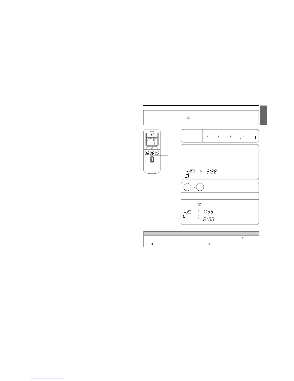
1
Set the ON-timer.
Set the current time at first if it is not set before (see the pages for setting
the current time). Press the (SLEEP) button, and the display changes as
shown below.
Mode
Sleep timer
Indication
1 hour 2 hours 3 hours 7 hours
Sleep timer off
Sleep Timer: The device will continue working for the designated
number of hours and then turn off.
Point the signal window of the remote controller toward the indoor
unit, and press the SLEEP button.
The timer information will be displayed on the remote controller.
The TIMER lamp lights with a beep from the indoor unit. When the
sleep timer has been set, the display indicates the turn-off time.
Example: If you set 3 hours sleep
time at 11:38 p.m., the turn-off
time is 2:38 a.m.
2
Press the (SLEEP) button and set the sleep timer.
The device will be turned off by the sleep
timer and turned on by on-timer.
How to Cancel Reservation
Point the signal window of the remote controller toward the indoor unit, and press the (CANCEL)
button.
The (RESERVED) sign goes out with a beep and the (TIMER) lamp turns off on the indoor unit.
For heating:
In this case, the device will turn off
in 2 hours (at 1:38 a.m.) and it will
be turned on 6:00 next morning.
H
AM
H
AM
AM
Sleep
timer
Start
SLEEP
HOW TO SET THE SLEEP TIMER
Page 18
– 16 –
ENGLISH
– 12 –
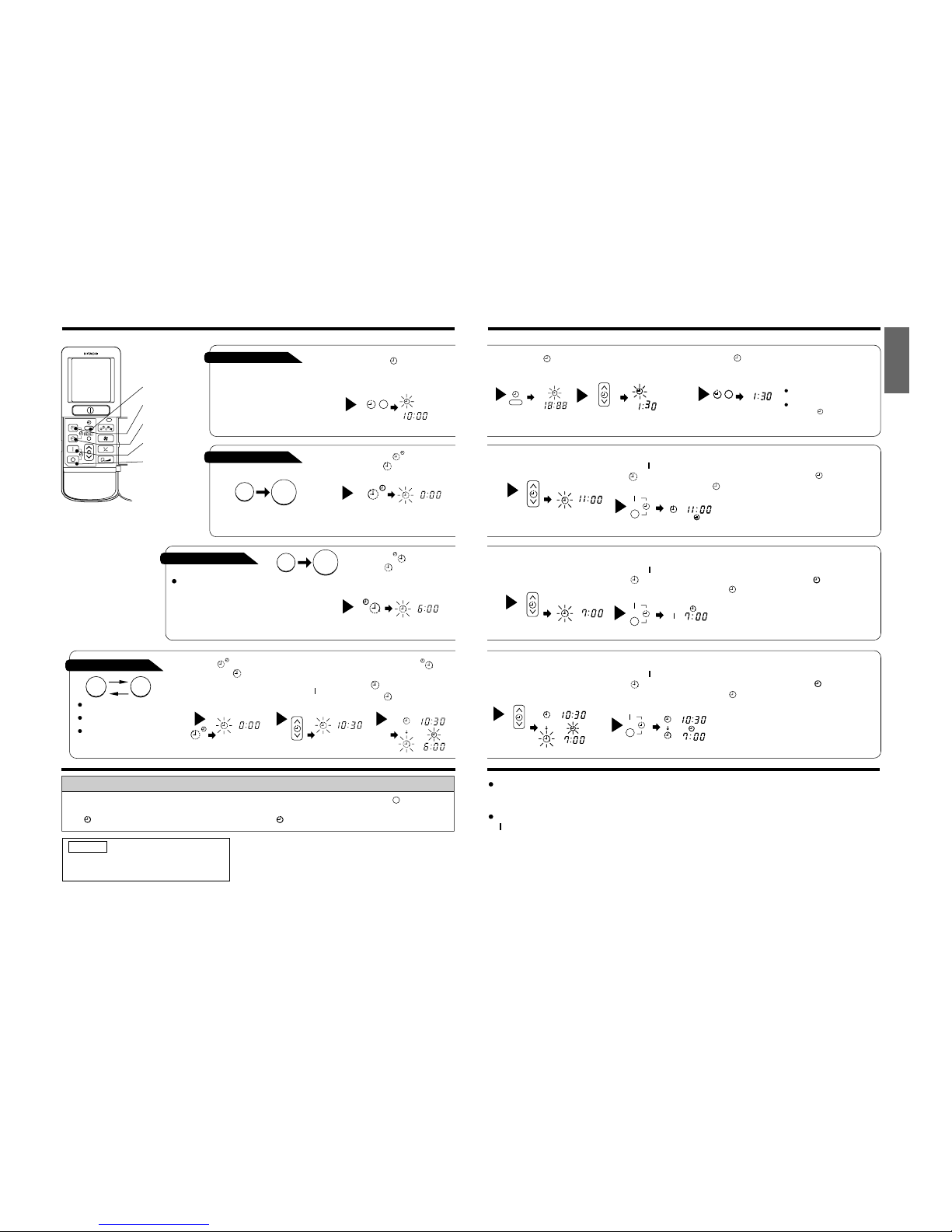
ON/OFF-Timer
The device will turn on (off) and off
(on) at the designated times.
The switching occurs first at the
preset time that comes earlier.
The arrow mark appearing on the
display indicates the sequence of
switching operations.
1
Press the (ON-OFF)
button so that the (OFF)
mark blinks.
OFF-Timer
You can set the device to turn off
at the present time.
After you change the
batteries;
How to Cancel Reservation
Point the signal window of the remote controller toward the indoor unit, and press the (CANCEL)
button.
The (RESERVED) sign goes out with a beep and the (TIMER) lamp turns off on the indoor unit.
1
Set the (TIME) button.
1
Press the (OFF-TIMER)
button. The (OFF) mark blinks
on the display.
1
Press the (ON-TIMER)
button the (ON) mark blinks
on the display.
2
Set the turn-off time
with the TIMER control
button.
Press the (RESERVE)
button.
3
Press the (ON-
TIMER) button so that the
(OFF) mark lights and
the
(ON) mark blinks.
NOTE
You can set only one of the OFF-timer,
ON-timer and ON/OFF-timer.
ON-Timer
Time
The device will turn on
at the designated times.
TIME
OFF TIMER
ON TIMER
RESERVE
CANCEL
AM
PM
STOP
Start
AM
Start
Stop
AM
Start Stop
PM
PM
AM
PM
HOW TO SET THE TIMER
– 13 –
3
Point the signal window of the remote controller toward the indoor unit, and
press the (RESERVE) button.
The
(OFF) mark starts lighting instead of flashing and the sign (RESERVED)
lights. A beep occurs and the (TIMER) lamp lights on the indoor unit.
The time indication will disappear
automatically in 10 second.
To check the current time setting,
press the (TIME) button twice.
The setting of the current time is
now complete.
The timer may be used in three ways: off-timer, on-timer, and ON/OFF (OFF/ON)-timer. Set the
current time at first because it serves as a reference.
As the time settings are stored in memory in the remote controller, you only have to press the
(RESERVE) button in order to use the same settings next time.
2
Press the
(TIME) button.
3
Set the current time with the
TIMER control button.
Example: The current time is 1:30 p.m.
2
Set the turn-off time with the
TIMER control button.
The setting of turn-off time is now complete.
Example: The device will turn off at 11:00p.m.
Example:
The device will turn on at 7:00 a.m.
The setting of the turn-on time is now complete.
4
Set the turn-on time with the
TIMER control button.
5
Point the signal window of the remote controller toward the indoor unit, and
press the (RESERVE) button.
The
(ON) mark starts lighting instead of flashing and the (RESERVED)
sign lights. A beep occurs and the
(TIMER) lamp lights on the indoor unit.
3
Point the signal window of the remote controller toward the indoor unit, and
press the (RESERVE) button.
The
(ON) mar k starts lighting instead of flashing and the (RESERVED)
sign lights. A beep occurs and the (TIMER) lamp lights on the indoor unit.
2
Set the turn-on time with the
TIMER control button.
Example:
The device will turn off at 10:30 p.m. and it will be turned on
at 7:00 a.m.
The settings of the turn-on/off times are now complete.
4
Press the (TIME) button again.
The time indication starts lighting
instead of flashing.
AM
PM
AM
PM
AM
PM
AM
PM
PM
AM
PMPMPM
PM
PMPMPM
PM
AMAMAM
AM
Page 19
– 17 –
ENGLISH
– 14 –
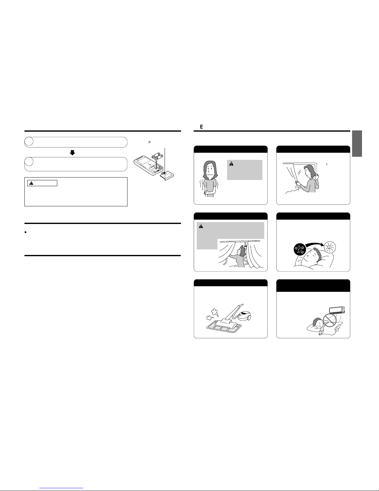
1
Remove the cover as shown in the figure and take out the
old batteries.
2
Install the new batteries.
The direction of the batteries should match the marks in the
case.
1. Do not use new and old batteries, or different kinds of batteries
together.
2. Take out the batteries when you do not use the remote controller
for 2 or 3 months.
Push and pull to the
direction of arrow
When you do not use the room air conditioner, set the circuit breaker to “OFF”.
If the remote controller does not work due to battery failure, press this switch to start and stop operation.
This temporary operation will be at the setting made most recently. (The unit will immediately go into
automatic operation once power is switched on.)
HOW TO EXCHANGE THE BATTERIES IN THE REMOTE CONTROLLER
CAUTION
TEMPORARY SWITCH
CIRCUIT BREAKER
– 15 –
Suitable Room Temperature Install curtain or blinds
Ventilation Effective Usage Of Timer
Do Not Forget To Clean The Air Filter
Please Adjust Suitable Temperature
For Baby And Children
Warning
Freezing temperature
is bad for health and a
waste of electric power.
It is possible to
reduce heat
entering the
room through
windows.
At night, please use the “OFF or ON timer
operation mode”, together with your wake up
time in the morning. This will enable you to
enjoy a comfortable room temperature. Please
use the timer effectively.
Dusty air filter will reduce the air volume and
the cooling efficiency. To prevent from wasting
electric energy, please clean the filter every 2
weeks.
Please pay attention to the room temperature
and air flow direction when operating the unit
for baby, children and old folks who have
difficulty in movement.
Caution
Do not close the room for a long period of
time. Occasionally open the door and windows
to allow the
entrance of
fresh air.
THE IDEAL WAYS OF OPERATION
Page 20
– 18 –
– 16 –
The Air Conditioner And The Heat Source In The Room
Not Operating For A Long Time
When Lightning Occurs
Caution
If the amount of heat in the room is above the cooling
capability of the air conditioner (for example: more
people entering the room, using heating equipments
and etc.), the preset room temperature cannot be
achieved.
When the indoor unit is not to be used for a long
period of time, please switch off the power from the
mains. If the power from mains remains “ON”, the
indoor unit still consumes about 8W in the operation
control circuit even if it is in “OFF” mode.
Warning
To protect the whole unit during lightning, please
stop operating the unit and remove the plug from the
socket.
OFF
Interference From Electrical Products
Caution
To avoid noise interference, please place the indoor
unit and its remote controller at least 1m away from
electrical products.
Inverter-type
fluorescent
lamp.
To prevent
interference,
place at least
1m away.
TV
FOR USER’S INFORMATION
ENGLISH
– 17 –
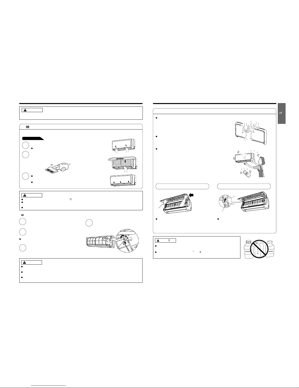
1
Open the front panel.
Pull up the front panel by holding it at both sides
with both hands.
2
Remove the filter.
Push upward to release the claws and pull out the
filter.
3
Attaching the air cleansing filters to the filter.
Attach the air cleansing filters to the frame by gently
compress its both sides and release after insertion
into filter frame.
4
Attach the filters.
Attach the filters by ensuring that the surface written
“FRONT” is facing front.
After attaching the filters, push the front panel at
three arrow portion as shown in figure and close it.
Cleaning and maintenance must be carried out only by qualified service personal. Before cleaning,
stop operation and switch off the power supply.
CAUTION
CAUTION
Do not bend the air cleansing
filter as it may cause damage to
the structure.
NOTE
In case of removing the air cleansing filters, please follow the above procedures.
The cooling capacity is slightly weakened and the cooling speed becomes slower when the air cleansing
filters are used. So, set the fan speed to "HIGH" when using it in this condition.
Do not operate the air conditioner without filter. Dust may enter the air conditioner and fault may occur.
Claws
(4 places)
AT TACHING THE AIR CLEANSING FILTERS
Page 21
– 19 –
– 18 –
MAINTENANCE
Cleaning and maintenance must be carried out only by qualified service personal. Before cleaning, stop operation and
switch off the power supply.
1. AIR FILTER
Clean the air filter, as it removes dust inside the room. In case the air filter is full of dust, the air flow will decrease and
the cooling capacity will be reduced. Further, noise may occur. Be sure to clean the filter following the procedure below.
CAUTION
1
Open the front panel and remove the filter
Gently lift and remove the air cleansing filter from the air filter frame.
2
Vacuum dust from the air filter and air cleansing filter using vacuum
cleaner. If there is too much dust, air filter only rinse under running tap
water and gently brush it with soft bristle brush. Allow filters to dry in
shade.
3
Re-insert the air cleansing filter to the filter frame. Set the filter with
“FRONT” mark facing front, and slot them into the original state.
After attaching the filters, push the front panel at three arrow portions
as shown in figure and close it.
CAUTION
Do not wash with hot water at more than 40°C. The filter may shrink.
When washing it, shake off moisture completely and dry it in the shade; do not expose it directly to the sun. The filter
may shrink.
Do not use detergent on the air cleansing filter as some detergent may deteriorate the filter electrostatic performance.
PROCEDURE
Servicing the electrical dust collector’s electrical terminals
1
Use the remote control to stop all operations and
remove the electrical power plug (or push the
circuit breaker to its “OFF” position)
2
Remove the front panel (For the front panel
removal instructions, refer to page 19)
3
Using a toothbrush, remove all dirt from the
electrical dust collector’s electrical terminals.
Brushing the electrical terminals with a toothbrush will
remove the dirt (must use a dry toothbrush).
4
Re-install the front panel (For the front panel reinstallation instructions, refer to page 19) insert
the electrical plug (or push the circuit breaker to
its “ON” position)
Lift up to open the cover
Electrical dust collector’s
electrical terminals
CAUTION
Before servicing, use the remote control to switch off all operations and pull out the electrical plug (or push the
circuit breaker to its “OFF” position)
Do not touch the electrical terminals when the electrical dust collector is operating. High tension electrical power
may cause serious electric shocks.
Caution should be taken to prevent the electrical dust collector’s electrical terminals from coming into contact with
water, as it may cause serious electric shocks.
ENGLISH
– 19 –
2. Washable Front Panel
Remove the front panel and wash with clean
water.
Wash it with a soft sponge.
After using neutral detergent, wash thoroughly
with clean water.
When front panel is not removed, wipe it with
a soft dry cloth. Wipe the remote controller
thoroughly with a soft dry cloth.
Wipe the water thoroughly.
If water remains at indicators or signal
receiver of indoor unit, it causes trouble.
Method of removing the front panel.
Be sure to hold the front panel with both hands
to detach and attach it.
CAUTION
Do not splash or direct water to the body of the unit when cleaning
it as this may cause short circuit.
Never use hot water (above 40°C), benzine, gasoline, acid, thinner or
a brush, because they will damage the plastic surface and the coating.
Removing the Front Panel
When the front panel is fully opened with
both hands, push the right arm to the inside
to release it, and while closing the front panel
slightly, put it out forward.
Attaching the Front Panel
Move the projections of the left and right
arms into the Flanges in the unit and
securely insert them into the holes.
Arm
Projection
Hole
Flange
Page 22
– 20 –
– 20 –
1
2
3
PLEASE CHECK THE FOLLOWING POINTS BY QUALIFIED SERVICE PERSONAL EITHER
EVERY HALF YEARLY OR YEARLY. CONTACT YOUR SALES AGENT OR SERVICE SHOP.
Is the earth line disconnected or broken?
Is the mounting frame seriously affected by rust and is the
outdoor unit tilted or unstable?
Is the plug of power line firmly plugged into the socket?
(Please ensure no loose contact between them).
Cleaning and maintenance must be carried out only by qualified service personal. Before cleaning,
stop operation and switch off the power supply.
CAUTION
Confirm
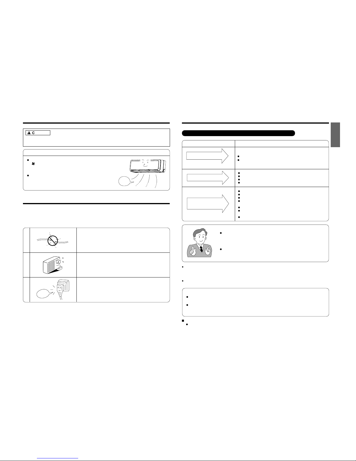
3. MAINTENANCE AT BEGINNING OF LONG OFF PERIOD
Running the unit setting the operation mode to
(FAN) and the fan speed to HI for about half
a day on a fine day, and dry the whole of the unit.
Switch off the power plug.
Air
Blow
REGULAR INSPECTION
ENGLISH
– 21 –
When it does not operate
Is the fuse all right?
Is the voltage extremely high or low?
Is the circuit breaker “ON”?
Is the setting of operation mode different from other indoor units?
Is the air filter blocked with dust?
Does sunlight fall directly on the outdoor unit?
Is the air flow of the outdoor unit obstructed?
Are the doors or windows opened, or is there any source of
heat in the room?
Is the set temperature suitable?
Are the air inlets or air outlets of indoor and outdoor units
blocked?
Is the fan speed “LOW” or “SILENT”?
CONDITION CHECK THE FOLLOWING POINTS
Notes
In quiet operation or stopping the operation, the following phenomena may
occassionally occur, but they are not abnormal for the operation.
(1) Slight flowing noise of refrigerant in the refrigerating cycle.
(2) Slight rubbing noise from the fan casing which is cooled and then
gradually warmed as operation stops.
The odor will possibly be emitted from the room air conditioner because the
various odor, emitted by smoke, foodstuffs, cosmetics and so on, sticks to it.
So the air filter and the evaporator regularly must be cleaned to reduce the
odor.
Please contact your sales agent immediately if the air conditioner still fails to operate normally after the above
inspections. Inform your agent of the model of your unit, production number, date of installation. Please also
inform him regarding the fault.
Power supply shall be connected at the rated voltage, otherwise the unit will be broken or could not reach the
specified capacity.
When it does not cool well
When it does not hot well
If the remote controller is
not transmitting a signal.
Do the batteries need replacement?
Is the polarity of the inserted batteries correct?
Remote controller
display is dim or blank.)
NOTE:
If the supply cord is damaged, it must be replaced by the special cord obtainable at authorized
service parts centers.
On switching on the equipment, particularly when the room light is dimmed, a slight brightness fluctuation
may occur. This is of no consequence.
The conditions of the local Power Supply Companies are to be observed.
The moveable panels are not moving
Check to ensure whether the front panels have been installed in a proper manner.
AFTER SALE SERVICE AND WARRANTY
WHEN ASKING FOR SERVICE, CHECK THE FOLLOWING POINTS.
Page 23

– 21 –
UTILISATION
PRÉCAUTIONS À SUIVRE
MODÈLES RAS-50WX8 / RAC-50WX8, RAS-D18EX3 / RAC-D18EX3
未入稿
Page 24
– 33 –
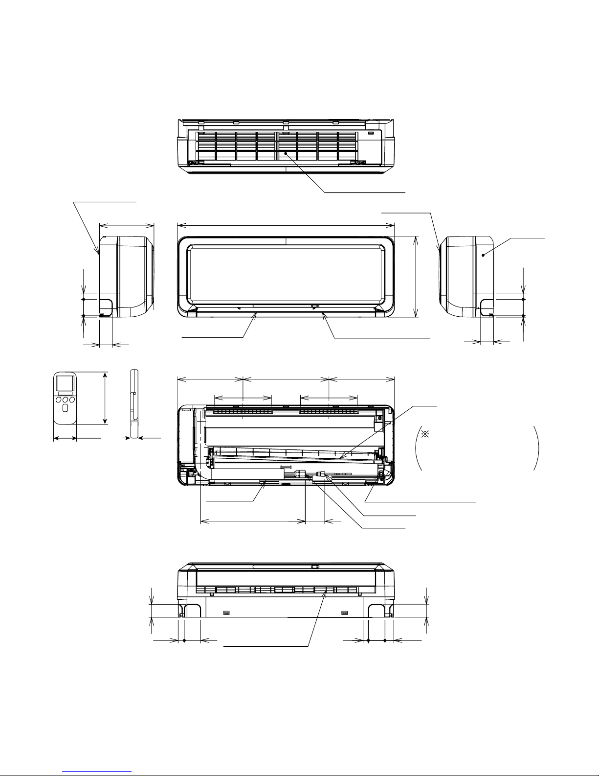
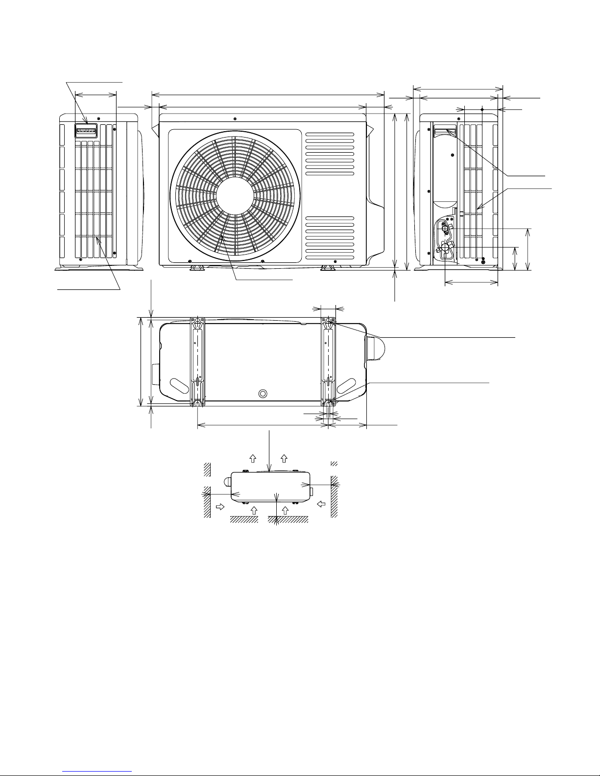
CONSTRUCTION AND DIMENSIONAL DIAGRAM
MODEL RAS-50WX8, RAS-D18EX3
Unit : mm
795
295
Horizontal air deflector
Discharge grill
Top air suction grill
47
560 20
Cabinet
Front panel
314
208
208
240 240
70about 370
Drain
Drain hose
Wide pipe
Narrow pipe
Drain cap connection port
When piping is
drawn from the left side,
exchange the drain
hose and the drain cap.
5
147
60 20
47
56
17.5
Mounting plate
INDOOR UNIT
47
3260196022
47
Vertical air deflector
198
Page 25

– 34 –
DIMENSIONS DES UNITÉS
MODÈLE RAS-50WX8, RAS-D18EX3
UNITÉ INTÉRIEURE
795
295
Déflecteur d'air horizontal
Grille d'évacuation
Grille supérieure d'aspiration de l'air
47
560 20
Boîtier
Panneau avant
314
208
208
240 240
70Environ 370
Vidange
Tu yau de vidange
Grosse tuyauterie
Petite tuyauterie
Orifice de fixation du bouchon de vidange
Lorsque la tuyauterie est
connectée du côté gauche,
remplacez le tuyau de
vidange par le bouchon
de vidange.
5
147
60 20
47
56
17.5
Plaque de montage
47
3260196022
47
Déflecteur d'air vertical
198
Unité : mm
Page 26

– 35 –
MODEL RAC-50WX8,RAC-D18EX3
68 60
202
Air
suction
91
162.5
299
27
345
(19)
Handle
792(26)
887
69
Air
outlet
589
600
(11)
157
Air
suction
Handle
Service space
10
500 147
320 (10)
37
12
340
57
Long holes for anchor bolt
(2-φ12×16 Long holes φ8.0 bolt)
Notch for anchor bolt
(2-φ8.0 bolt)
above
100
above
200
50
above
200
above
Note:
1.200mmormoreservicingspaceisrequiredabovetheoutdoorunit.
Unit : mm
Page 27
– 36 –
MODÈLE RAC-50WX8,RAC-D18EX3
68 60
202
Aspirationd'air
91
162.5
299
27
345
(19)
Poignée
792(26)
887
69
Sortiedel'air
589
600
(11)
157
Aspirationd'air
Poignée
Espacerequispourentretien
10
500 147
320 (10)
37
12
340
57
Longstrouspourverroudel'ancre
(2-φ12×16Longstrousφ8,0boulons)
Encochepourlesboulonsd'ancrage
(2boulonsφ8,0mm)
Supérieur
100
Supérieur
200
50
Supérieur
200
Supérieur
Remarqe:
1.200mmouplusd'espaceduserviceestexigé au-dessus de l'unité de plein air.
Unité : mm
Page 28
– 37 –
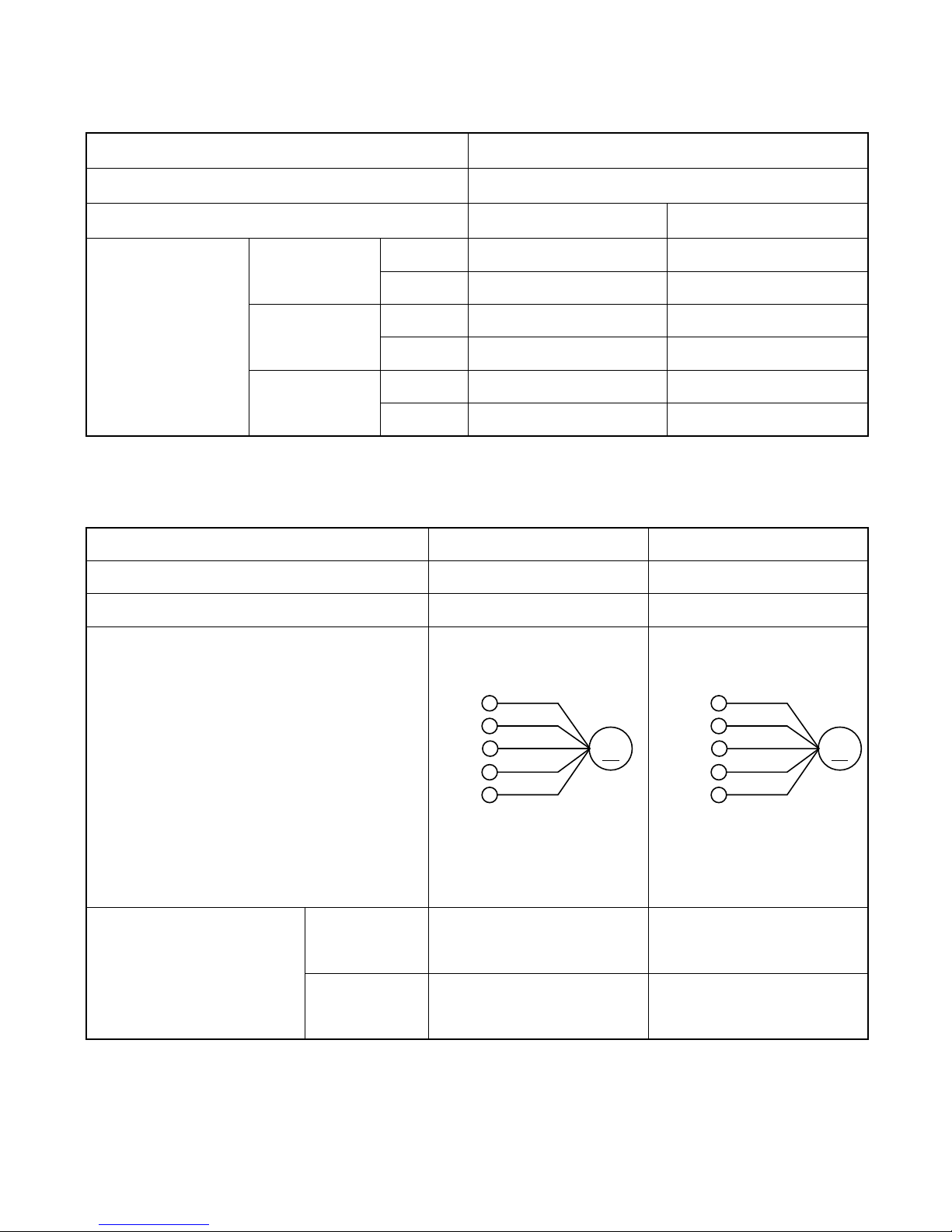
MAIN PARTS COMPONENT PRINCIPAUX COMPOSANTS
THERMOSTAT THERMOSTAT
Thermostat Specifications Caractéristiques du thermostat
FAN MOTOR MOTEUR DE VENTILATEUR
Fan Motor Specifications Caractéristiques du moteur de ventilateur
MODEL MODÈLE
RAS-50WX8, RAS-D18EX3
THERMOSTAT MODEL MODÈLE DE THERMOSTAT
IC C.I.
OPERATION MODE MODE DE FONCTIONNEMENT
COOL RÉFRIGÉRATION HEAT CHALEUR
MODEL MODÈLES RAS-50WX8, RAS-D18EX3 RAC-50WX8, RAC-D18EX3
POWER SOURCE SOURCE D'ALIMENTATION DC : 5V, DC : 0 - 35V DC : 120 - 380V
OUT PUT
WATT DE SORTIE NOMINALE
25W 47W
ON MARCHE
15.7 (60.3) 16.7 (62.1)
OFF ARRET
15.3 (59.5) 17.3 (63.1)
ON MARCHE
23.7 (74.7) 24.7 (76.5)
OFF ARRET
23.3 (73.9) 25.3 (77.5)
ON MARCHE
31.7 (89.1) 32.3 (90.1)
OFF ARRET
31.3 (88.3) 32.7 (90.9)
TEMPERATURE
TEMPÉRATURE
˚C (˚F)
INDICATION
INDICATION
16
INDICATION
INDICATION
24
INDICATION
INDICATION
32
CONNECTION
CONNEXION
20˚C
(68˚F)
75˚C
(167˚F)
––– –––
––– –––
(Control circuit built in)
(Circuit de commande incorporé) (Circuit de commande incorporé)
(Control circuit built in)
M
WHT
RED
YEL
0-5V
0V
35V
5V
BLU
BLK
M
BLK
RED
WHT
15V
120-380V
0-6.5V
0V
YEL
BLU
BLU : BLUE YEL : YELLOW BRN : BROWN WHT : WHITE
BLEU JAUNE BRUN BLANC
GRY : GRAY ORN : ORANGE GRN : GREEN RED : RED
GRIS ORANGE VERT ROUGE
BLK : BLACK PNK : PINK VIO : VIOLET
NOIR ROSE VIOLET
RESISTANCE VALUE
VALEUR DE RESISTANCE
(Ω)
Page 29
– 38 –
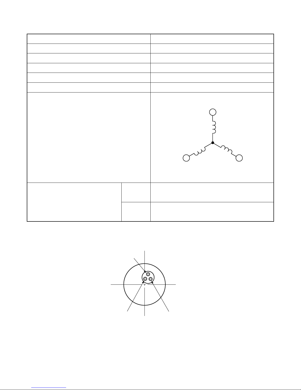
COMPRESSOR COMPRESSEUR
Compressor Motor Specifications Caractéristiques du moteur de compresseur
CONNECTION
CONNEXION
RESISTANCE VALUE
VALEUR DE RESISTANCE
(Ω)
(U)
WHITE
BLANC
YELLOW
JAUNE
RED
ROUGE
(V)
M
M
M
(W)
MODEL MODÈLE RAC-50WX8, RAC-D18EX3
COMPRESSOR MODEL MODÈLE DE COMPRESSEUR EU1013E2
PHASE PHASE SINGL SIMPLE
RATED VOLTAGE TENSION NOMINALE DC280 - 330V
RATED FREQUENCY FREQUENCE NOMINALE 50 / 60Hz
POLE NUMBER NOMBER DE POLES 4
20˚C
(68˚F)
75˚C
(167˚F)
2M = 0.74
2M = 0.90
WHITE
BLANC
YELLOW
JAUNE
RED
ROUGE
Page 30
– 39 –
BLU : BLUE
YEL : YELLOW
BRN : BROWN
WHT : WHITE
GRY : GRAY
ORN : ORANGE
GRN : GREEN
RED : RED
BLK : BLACK
PNK : PINK
VIO : VIOLET
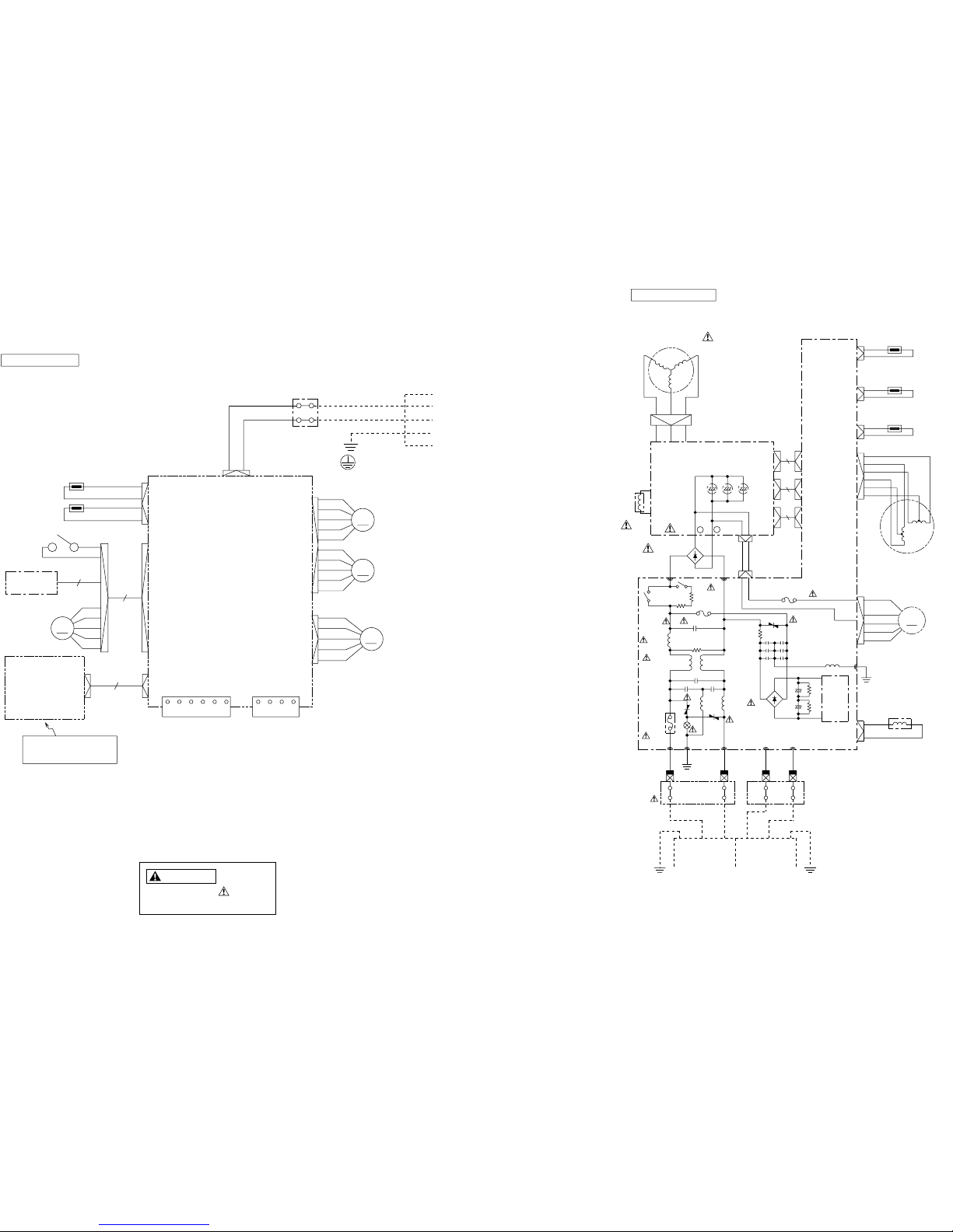
WIRING DIAGRAM
MODEL RAS-50WX8 / RAC-50WX8
RAS-D18EX3 / RAC-D18EX3
CAUTION
The marked parts are very
important ones for safety.
INDOOR UNIT
OUTDOOR UNIT
CIRCUIT
SW POWER
BLK
BLK
REVERSING
VALVE
GRY
GRY
GRY
GRY
PNK
WHT
YEL
ORN
BLU
BRN
RED
PNK
GRN
FAN
MOTOR
ELECTRIC EXPANSION
VALVE
OUTDOOR
TEMPERATURE
THERMISTOR
DEFROST
THERMISTOR
OVER HEAT
THERMISTOR
COMPRESSOR
WHT
WHT
YEL
YEL
RED
RED
BLK
RED
WHT
YEL
BLU
WHT
25A
FUSE
MAIN P.W . B .
(
BRN
)
(
RED
)
BRN RED
LN
TERMINAL
BOARD
(
BLK
)
(
WHT
)
BLK
WHT
(
GRN+YEL
)
GRN
CONNECTING
CORD
C
D
+
-
〜
〜
UVW
+
-
+
-
L001
〜
L002
CT1
〜
CN15
CN10
RED
CN9
BLU
CN8
WHT
-++-
CN13
CN13
5
CN14
10
CN14
CN11
CN11
5
CN12
CN12
CN6
WHT
RED
L2
L1
CN2
M
DIODE
STACK
VARISTOR2
2A FUSE
NF
COIL1
COIL
3A FUSE
POWER
RELAY
STACK
DIODE
SURGE ABSORBER
VARISTOR1
VARISTOR3
SYSTEM
POWER MODULE
GRY
YEL
BLU
RED
YEL
REACTOR
YEL
-
+
C003
C006
R001
C002
C001
R007
+
+
R011
R010
C011
C010
C014
C015
C013
C008
C012
C007
R002
RELAY
ICP
R008
(
GRN+YEL
)
POWER SOURCE
AC220-230V
50Hz
M
CN11
M
CN10
CN3
CN7
CN9
4321
CN2
9
CN2
INDOOR
FAN MOTOR
RED
BLK
WHT
YEL
BLU
GRY
WIRELESS REMOTE
CONTROL
CONTROL
P. W . B .
WIRED
REMOCON
H-LINK
1 23456
12V Rx Tx 0V
0V 12V Rec Send
M
CN1
GRY
CN4
AUTO SWEEP
MOTOR2
AUTO SWEEP
MOTOR1
INDICATION
,
TEMPORARY SW
AND
LIGHT RECEIVING UNIT
P. W . B .
BLK
BLK
11
M
4
D
C
BRN
RED
CONNECTING
TERMINAL BOARD
CORD
(
BRN
)
(
GRN&YEL
)
HEAT
EXCHANGER
THERMISTOR
ROOM
THERMISTOR
TEMPEATURE
FRONT PANEL
MOTOR
LIMIT
SWITCH
(
RED
)
IONIZER
Page 31

– 41 –
BLU : BLEU
YEL : JAUNE
BRN : BRUN
WHT : BLANC
GRY : GRIS
ORN : ORANGE
GRN : VERT
RED : ROUGE
BLK : NOIR
PNK : ROSE
VIO : VIOLET
SCHÉMA ÉLECTRIQUE
MODÈLE RAS-50WX8 / RAC-50WX8
ATTENTION
Les composants comportant le symbole
sont très importants pour la sécurité.
UNITÉ INTÉRIEURE
UNITÉ EXTÉRIEURE
COMMUTATION
ALIMENTATION
BLK
BLK
GRY
GRY
GRY
GRY
PNK
WHT
YEL
ORN
BLU
BRN
RED
PNK
GRN
THERMISTANCE DE
TEMPÉRATURE
EXTÉRIEURE
THERMISTANCE
DE DÉGIVRAGE
THERMISTANCE
DE SURCHAUFFE
VANNE D'EXPANSION
ÉLECTRIQUE
MOTEUR DE VENTILATEUR
VANNE D'INVERSION
COMPRESSEUR
WHT
WHT
YEL
YEL
RED
RED
BLK
RED
WHT
YEL
BLU
WHT
25A
FUSIBLE
C.I. PRINCIPAL
(
BRN
)
(
RED
)
BRN RED
LN
BORNIER DE
RACCORDEMENT
(
BLK
)
(
WHT
)
BLK
WHT
(
GRN+YEL
)
GRN
CORDON DE
CONNEXION
C
D
+
-
〜
〜
UVW
+
-
+
-
L001
〜
L002
CT1
〜
CN15
CN10
RED
CN9
BLU
CN8
WHT
-++-
CN13
CN13
5
CN14
10
CN14
CN11
CN11
5
CN12
CN12
CN6
WHT
RED
L2
L1
CN2
M
PILE DE
DIODE
VAR ISTANCE 2
2A FUSIBLE
BOBINE 1 NF
BOBINE
3A FUSIBLE
RELAIS
D'ALIMENTAION
PILE DE
DIODE
MONTEZ L'AMORTISSEUR
VARISTANCE 1
VARISTANCE 3
MODULE D'ALIMENTATION
DU SYSTÈME
GRY
YEL
BLU
RED
YEL
RÉACTEUR
YEL
-
+
C003
C006
R001
C002
C001
R007
+
+
R011
R010
C011
C010
C014
C015
C013
C008
C012
C007
R002
RELAIS
ICP
R008
(
GRN+YEL
)
ALIMENTATION
CA220-230V
50Hz
MOTEUR DE VENTILATEUR
INTÉRIEUR
MOTEUR DU
TABLEAU
FRONTAL
C.I. CONTRÔLE
TÉLÉCOMMANDE
AVEC CÂBLE
MOTEUR 1 DE BALAYAGE
AUTOMATIQUE
MOTEUR 2 DE BALAYAGE
AUTOMATIQUE
CORDO DE CONNEXION
BORNIER DE
RACCORDMENT
M
CN11
M
CN10
CN3
CN7
CN9
4321
CN2
9
CN2
RED
BLK
WHT
YEL
BLU
GRY
TÉLÉCOMMANDE
SANS FIL
H-LINK
1 23456
12V Rx Tx 0V
0V 12V Rec Send
M
CN1
GRY
CN4
INDICATEURS
INTERRUPTEUR
TEMPORAIRE
MODULE DE RÉCEPTION
DE LUMIÈRE C. I.
BLK
BLK
11
M
4
D
C
BRN
RED
(
BRN
)
(
GRN&YEL
)
THERMISTANCE
D'ÉCHANGEUR
DE CHALEUR
THERMISTANCE
DE TEMPÉRATURE
DE LA PIÈCE
INTERRUPTEUR
LIMITEUR
(
RED
)
IONIZER
RAS-D18EX3 / RAC-D18EX3
Page 32

– 43 –
WIRING DIAGRAM OF THE PRINTED WIRING BOARD
SCHÉMA ELÉCTRIQUE DU CIRCUIT IMPRIMÉ
[Remote controller] RAR-3U4
[Télécommande] RAR-3U4
LCD1
SW1
SW−187−2P
JSW2
JSW1
+
-
C2
1μF / 50V
R15 18Ω
C5
18pF
C4
22pF
X2
32. 768KHz
C7
1μF
C6
1μF
SW2
RESETKEY
(SW-RUBBER)
D3
1SS355
R11
100kΩ
X1 4MHz
03GES
13GES
02P
1
2P
22P
3
2P
42P
52P
62P
72P
SSV
TUOX
NIX
TUOCX
N
ICX
TESER
04
P
14P
24P
34P
04
9
3
83
73
63
53
43
33
2
3
13
0
3
92
82
7
2
62
52
42
32
22
12
1 2 3 4 5 6 7 8 9 10 11 12 13 14 15 16 17 18 19 20
P67
P66
P65
P64
P63
P62
P61
P60
P57
P56
P55
P54
P53
P52
P51
P50
P47
P46
P45 P44
SEG10
SEG11 SEG12 SEG13 SEG14 SEG15 SEG16 SEG17 SEG18 SEG19 SEG20 SEG21 SEG22 SEG23 SEG24 SEG25 SEG26 SEG27 SEG28 SEG29
60
59
58
57
56
55
54
53
52
51
50
49
48
47
46
45
44
43
42
41
9GE
S
8GES
7GES
6GES
5GES
4GES
3G
E
S
2GES
1GES
0GE
S
CCV
FERV
SSVA
3MOC
2MOC
1MOC
0MOC
3LV
2LV
1LV
1
6
26
36
46
56
66
76
8
6
9
6
07
17
27
37
47
57
67
77
87
97
08
PS1〜PS12
C8 0.1μF
R12
220kΩ
R1
3.3Ω
(
1/8W)
R2
3.3Ω
(
1/8W)
R3
3.3Ω
(
1/8W)
R4
3.3Ω
(
1/8W)
R7
220Ω
R8
1kΩ
R6
2. 2kΩ
Q2
2SC3443
Q1
2SA1235
D1
EL−1L7
D2
EL−1L7
R10
220kΩ
R9
10MΩ
IDJS
R13
220kΩ
R14
220kΩ
R5
1.2kΩ
C9 0.1μF
TP1
COM3
COM2
COM1
COM0
TP2
TP3
01 02 03 04
05 06 07 08
09 10 11 12
IC1
R16
4.7kΩ
+
−
NC
NC
NC
NC
NC
NC
NC
NC
NC
M38235G6−XXXHP
12345678
12345678
A
B
C
D
E
F
A
B
C
D
E
F
SEG0
SEG1
SEG2
SEG3
SEG4
SEG5
SEG6SEG7
SEG8
SEG9
SEG10
SEG11
SEG12
SEG13
SEG14
SEG15
SEG16
SEG17
SEG18
SEG19
SEG20
SEG21
SEG22
SEG24
SEG23
SEG25
SEG26
INPUT
ENTRÈE
OUTPUT
PRODUCTION
Page 33

WIRING DIAGRAM OF THE PRINTED WIRING BOARD
MODEL RAS-50WX8, RAS-D18EX3
R
A
Axial
H
Chip
C
Symbol
Shape
Radial
Manual
R751
L751
R631
C131
C751
C621
C132
ZD131
D121
5V
C121
IC121
C123
C122
-
0V
+
ZD121
OUT
GNG
IN
R122
R123
Q115
C101
D101
IC111
6
4
7
2
3
8
5
C111
Q116
R124
R121
Q111
R114
R118
Q113
Q112
C103
35V
C112
ICP2
R111
R115
C115
C113
C116
R112
L111
ZD111
C114
R116
R119
ICP1
-
R117
-
+
L101
C102
+
1
C304
C303
C302
3
4
CN1
R306
R307
R305
R301
R302
R303
5V
M
CN10
1
2
3
4
5
6
C631
R813
R812
0V
5V
R821
C821
C802
5V
0V
+
-
-
+
R829
R828
R827
R822
R826
Q821
R825
R823
D821
R824
C823
IC801
R803
R805
R806
R807
IC801
C801
R811
R810
Q803
Q802
C822
R804
7
5
1
3
2
6
4
8
Q801
R830
C825
C824
0V
4
3
2
1
8
7
6
5
IC401
C401
R403
R404
R401
R402
0V
D401
5V
5V
5V
R611
C611
R502
R501
RES1
C524
C506
5V
L501
C502
C501
0V
C505
C507
R510
R641
0V
R509
R507
R506
R508
R504
ID
R621
C
D
CN3
3
2
1
1
3
M
9
8
79
7
10
11
12
6
5
4
13
3
14
2
15
1
16
8
IC711
Vss
10
RES
P10
P53
P12
PWM
P52
SDA
2120 23224919 24 3029 32312625 2827
P87
RXD
P20
SCL
P75
P74
AN6
AN7
P85
P70
P86
P23
48
46
40
41
39
44
45
42
43
506364 5455 525357
IC501
SDA
SCL
TXD
51
AN3
P54
P55
AN1
AN2
AN4
AN0
2
1
3
P17
P14
P16
P15
P24 TXD2
RXD2
EEPROM
X1
4
5
8
TEST
7
6
1817
16
P36
P34
P37
13
12
WKP0
14
11
WKP1
34
33
35
36
NMI
37
P61
P60
38
47
56585962 6061
15
X2
VCL
OSC2
OSC1
Vcc
P35
P64
P33
P31
P30
P32
TMOV
FTIOD0
9
P62
FTI0B1
FTI0C1
FTI0D1
A
R601
R602
C601
R651
R652
C651
R654
R656
R655
R653
R767
R766
R765
5V
R551
C521
C522
2
531
IC521
R552
C523
Q521
R762
AUTORESTART
OFF
R642
JW601
CN8
2
L752
(
BRN
)
(
RED
)
Heat exchanger
Thermistor
XA-3P-Top
XA-6P-Top
Indoor
Fan Motor
HEAT EXCHANGER
POWER SUPPLY VOLTAGE
FAST FEED
TEST
RESET
CLOCK
OSCILLATION
CIRCUIT
WIRELESS INPUT
FM ROTATION NO. FB
AUTO
SWEEP1
AUTO SWEEP2
POWER SUPPLY CONTROL OUTPUT2
POWER SUPPLY CONTROL OUTPUT1
DC FAN OUTPUT
HIGH VOLTAGE DIFECTION
HIGH VOLTAGE OUTPUT
BUZZER
HA O/P
TIMER
OPERATION
HUMIDITY
FILTER
HOT KEEP
POWERFUL
LED INDICATION O/P
REMOTE CONTROL ID SELECT
OUTSIDE RXD
OUTSIDE TXD
AUTO RESTART
HA INPUT
I/F RECEPTION
I/F TRANSMISSION
STATIC PRESSURE SELECT
INSTALLATION PLACE SELECT
DRAIN PUMP TESTING OPERATION
ABNORMAL WATER LEVEL DETECTION
φ1φ2φ3
φ4
FLONT PANEL
M
M
3
2
1
5
4
6
5
4
13
3
14
2
15
1
16
8
9
7
10
11
12
0V
8
7
6
9
ROOM TEMPERATURE
AN5
HUMIDITY
H-LINK
12V
FLONT PANEL LIMIT SW
UN USE
0V
WIRED
REMOCON
CLEAN LANP
ION LANP
INDOOR FAN PWM OUTPUT
HOT KEEP
R752
R753
R754
R768
IC712
CN11
R503
Stepping Motor
for auto sweep1
Stepping Motor
for Front Panel
Stepping Motor
for auto sweep2
CZ-10P-Top
PH-5P-Top
3
2
1
5
4
CN12
R763
R756
R757
R514
R515
R513
R505
+ve DISPLAY
-ve DISPLAY
C509
R755
C714
3
4
5
6
3
4
5
6
PH-11P-Top
CN4
FRONT PANEL
LIMIT SW
Q121
ICP3
C134
R523
2
1
PH-4P-Top
Room Temperature
Thermistor
R721
BZ1
BZ
Q722
CN14
3
4
5
6
7
8
9
Relay
Connector1
XM-11P
1
2
1
2
R758
XH-3P-Top
Relay
Connector2
GND
Electrode
IONIZER
LED
LD201
LD202
LD203
H
H
1608
1608
Color
Use
Yellow
Orange
− −
Green
H
C
Use
3216
C
1608
Use
C
Q112 2SC5209H
Q113 2SC5209H
C
C
C
C
C
C
Q111 2SJ518
Q115
Q116
2SA1162Y
Q722
Model
Model
Model
Model
Model
Model
DTC114EETL
DTC114EETL
C
Q121 KTC3875S
Q141 2SC2462LC
C
CQ521 DTC114EETL
CQ723 DTC114EETL
25V
C502 25V
C631 1000P 50V
C801
C802
C821
C822
C751
C621
C
C601 25V
C
(B)
C
(F)
C711 25V
(F)
25VC521
C
(F)
10VC522
C
16V
C501
C823
50V F
50V F
150P 50V
1000P 50V
25V
C824 50V
25VC505
50VC611 1000P
C524 25V
C
(B)
(B)
C
(B)
C
(B)
25VC523
C
(F)
C
C
C
C
C
C
(F)
(F)
(F)
(F)
(F)
(F)
25VC506
C
(F)
25VC507
C
(F)
C825
C651 25V
C
(F)
C
C
C
C
C
C
C
C
C
C
C
C
C
C
C
C
C
C
C
C
R
R
C803
C804
C712 25V
(F)
C
C
C713 25V
C
C
(F)
50V
C
(F)
1000P 50V
C
(B)
C
C531
C508 25V
C
(F)
C
C714 25V
C
(F)
C
C509 25V
C
(F)
C
(CH)
−
− − − −
− − −
− − −
−−−−−
(
LXZ
)
(
LXZ
)
(
SMG
)
C101 0.22µ
2.2µ
0.1µ
0.1µ
0.1µ
47µ
0.1µ
0.1µ
0.1µ
0.1µ
0.1µ
0.1µ
0.1µ
0.1µ
0.1µ
0.1µ
0.1µ
0.1µ
0.1µ
0.1µ
0.15µ
0.01µ
0.01µ
0.047µ
1µ
0.22µ
0.1µ
0.1µ
0.1µ
0.1µ
0.1µ
0.1µ
0.1µ
0.1µ
0.1µ
0.1µ
47µ
100µ
0.22µ
0.047µ
50V F
C102 50V
D
C111 10V
C121 25V
C122 10V
C304 25V
C401 25V
330µ
220µ
25VC302
C113
C
(B)
C303 25V
C114 25V
C115
D
D
C123 25V
C103
C131 50V
C132 25V
630V
C470p
C
C
C
C
(F)
(F)
(F)
(F)
C
(B)
C112
C116
C211 16V
D
(MF)
C
(F)
C
(F)
C
(F)
1000P 50V
C
(B)
25V
C
(F)
R
C
C
C
C
C
C
C
C
C
C
C
C
R
R
R
R
C212
Voltage
Type
Capacitor
Transistor
C
C134 25V
C
(F)
C
R765 390
1/16W
R766
1/16W
1/16W
R767 390
300
R812
R813
39
1/8W
R821
39
1/8W
R822
1K
1/16W
10K
1/16W
R825
1/16W
R826
R827 3K
120K
1/16W
1/16W
1/16W
R811 2K
680
1/16W
1/16W
R829 5.1K
1/16W
1/16W
R810
R830 1K
1/16W
R751 2.7K
R762
1/16W
R828 10K
1/16W
1K
R824
R823 10K
8.25K
1/16W
1/16W
10K
R803
R804
120K
120K
1/16W
R805
R806
R807 4.3K
120K
C
C
C
C
C
A
C
C
C
C
C
C
C
C
C
C
C
C
C
C
C
C
C
1/8W
1/6W
R752
R753
R754
R755
10K
1/16W
C
10K
1/16W
C
2K
1/16W
C
R768
1/16W
1K C
R763 10K
1/16W
C
R756 1K
1/16W
C
R757 1K
1/16W
C
R758
5.1KR551 1M
1/16W
R552 1K
1/16W
R652
1/16W
100
10K
1/16W
R611 1K
R601 1K
R621
1/16W
R701 1K
1/16W
R656
1/16W
R654 10K
R655
1/16W
10K
1K
R631 1K
R721 3.3K
1/16W
R602
R641
1/16W
10K
1KR651
1/16W
1KR653
1/16W
1K
C
C
C
C
A
C
C
C
C
C
C
C
C
C
C
C
1/8W
1/4W
1/8W
1/8W
R642
1/16W
C1K
R657 1K C
1/8W
R221
R222
−
−−−−−
−
− −
1/16W
R302 12.7K
1/16W
R301 12.7K
1/16W
1/16W
R303 10K
27K
1/10W
6.8k
1/4W
R212 47
1/10W
R141
1/10W
2.7K
R211 1K
0.56
100
1/16W
1/8W
1/8W
30K
560
R111
R112
R114
R115
R116
R117
1/16W
1/16W
75KR118
R119
1/16W
750
68K
R121
R122
1/16W
100
R123
1/16W
33K
R124
1/16W
±5% ±5% ±5% ±5%
±5%
±5%
±5%
±5%
±5%
±5%
±5%
±5%
±5%
±5%
±5%
±5%
±5%
±5%
±5%
±5%
±5%
±5%
±5%
±5%
±1%
±1%
±1%
±1%
±5%
±5%
±5%
±5%
±5%
±5%
±5%
±5%
±5%
±5%
±5%
±5%
±5%
±5%
±5%
±5%
±5%
±5%
±5%
±5%
±5%
±5%
±5%
±5%
±5%
±5%
±5%
±5%
±5%
±5%
±5%
±5%
±5%
±5%
±5%
±5%
±5%
±5%
±5%
±5%
±5%
±5%
±5%
±5%
±5%
±5%
±5%
±5%
±5%
±5%
±5%
±5%
±1%
±1%
±2%
±2%
C
C
C
C
C
C
C
C
C
C
C
C
C
C
C
C
C
RESISTOR
Circuit's
Symbol
Numerical
Power
(W)
S
h
a
p
e
Common
diff.
Circuit's
Symbol
Numerical
Value(F)
S
h
a
p
e
Voltage
Type
Circuit's
Symbol
Numerical
Value(F)
S
h
a
p
e
Voltage
Type
Circuit's
Symbol
Numerical
Value(F)
S
h
a
p
e
Circuit's
Symbol
S
h
a
p
e
Circuit's
Symbol
S
h
a
p
e
Circuit's
Symbol
S
h
a
p
e
Model
Circuit's
Symbol
S
h
a
p
e
Model
Circuit's
Symbol
S
h
a
p
e
Circuit's
Symbol
S
h
a
p
e
Model
Circuit's
Symbol
S
h
a
p
e
Circuit's
Symbol
Shape
Shape
Circuit's
Symbol
Circuit's
Symbol
Shape
Circuit's
Symbol
S
h
a
p
e
Numerical
Value(H)
− − −
− − −
− − −
R306
1/16W
R307
1/16W
1K
1K
R305 1K
1/16W
R504 10K
1/16W
R403
R402
R401
R404
390
1/16W
390
1/16W
5.1K
1/16W
5.1K
1/16W
R502
1/16W
1/16W
R507 10K
1/16W
1/16W
R508 10K
1/16W
R509 10K
R510 10K
±5%
10K
±5%
10K
±5%
10K
±5%
10K
±5%
10K
±5%
10K
±5%
±5%
±5%
±5%
±5%
10K
1/16W
R514
1/16W
R501 1M
1/16W
R506 10K
C
C
C
C
C
C
C
C
C
C
C
C
C
C
C
C
R531 C
R503 C
1/16W
10K
CR513
1/16W
CR515
1/16W
CR505 10K
1/16W
R524
1/16W
C
CR525
1/16W
CR523
1/16W
1/16W
Jumper
Q801
Q802
Q803
Q821
2SC3441E
C
C
C
C
DTC114EE-TL
DTA114EE-TL
2SC5383
IRR
Sensor Unit
GP1UX511RK
H
PKM13EPYBZ1 H
Buzzer
CSTLS10M0G53
RES1 10MHz R
Oscillator
ZD111
ZD141
ZD121
ZD131
PTZ20A
RD5.6UJN2
RLZ6.8A
RD6.2UJN2CC
C
C
Zener Diode
SW1
EVQP05R-SW H
Switch
IC121
IC401
IC111
NJM2903MIC801
IC711 ULN2003ANS
NJM2340M
IC521 RN5VD42C
IC
IC501
C
C
C
C
C
BR24L04F-W
BA50BC0T
C
IC712 ULN2003ANS
C
H
L112
L751
L101
L111
Coil
0.6A
1.3A H
H
C
L801
C
CL752
1608CJ
1608CJ
L501
−
− −
− −
− −
−
−
C1608CJ
CN7
PH-12P-Top
CN1
CN2
CN3
CN4
CN6
CN10
CN2
H
H
H
H
H
H
H
H
CN8
Connecter
PH-4P-Top
CZ-9P-Top
XA-3P-Top
PH-11P-Top
XA-6P-Top
CN9
PA-4 P-Top
H
CN11
CN12
CZ-10P-Top
H
CN14
PA-6 P-Top
SJN-HOU-9P
H
H
D101
D401 HN1D03FU
Diode
DSM3MA2
D111
D821 1SS355
D121 1SS355
D1FS6
C
C
C
C
C
Jumper
JW601
JW801
S
iz
e
Use/
Don't Use
J100
〜
JW102
J121
CCP2E-20
ICP2 2.0ACCP2E-50
ICP1 0.8A
C
C
Over Current Protecter
Rating
Current
Model
Circuit's
Symbol
Shape
Model
Circuit's
Symbol
Shape
Model
Circuit's
Symbol
Shape
Rating
Current
ICP3 CCP2E-13C0.52A
0V
C803
C804
JW801
L801
C711
12V
C712
C713
55mA
25V
C
(F)
C
C2
11
9
NMI
12
PH-12P-TOP
C1C2
0V
12V
5V
R531
C531
Test
5V
SDA
SCL
RES
0V
1
2
3
4
RX
M2
TX
8
5
10
6
7
A
Terminal for EEPROM
data writing
CN6
Room Temp.
RX
TX
0V
12V
H-LINK
CN7
6
5
4
3
1
2
PA-6P-TOP
10
V-LED
C
C
10
11
11
10
R701
B
0V
3
4
5
CZ-9P-Top
CN2
9
6
7
8
2
12V
1
5V
0V
3
4
-
+
12V
5V
1
2
0V 0V
0V
REC
SEND
R911
R912
R913
R914
C911
C912
C913
R915
L911
L912
CN9
Wired Remocon
PA-4P-TOP
EER
GND
REM
Vin
(
ON/OFF
)
0V
1
2
3
4
PQ912
PQ911
R657
C508
R911
R912
R913
R914
R915
560
2K
620
1/10W
1/8W
C
C
C
C
C
1/10W
1/8W
1/8W
2K
C911
C912
C
(F)
C913
25V
D
25V
1000P 50V
C
(F)
R
C
C
L911
L912
A
A
A
Photocoupler
R524
R525
Display P.W.B.
LD202(Timer
)
LD201(Operation
)
LD203(Filter
)
Light
Temporary Sw.
C212
6
5
4
8
7
2
3
ZD141
Q141
R141
9
R212
R211
receiving
V
OUT
V
DD
GND
unit
C211
+
-
SW1
1
D403
5V
D403 1SS355 C
3
4
1
2
R221
R222
5V
L112
CT-4P-TOP
JW102
D111
SLR-332YC3F
SLR-332DC3F
SLR-332MC3F
HD64F36077GHV
(AX-7X30)
BL01RN1A1F1A
BL01RN1A1F1A
BL01RN1A1F1A
6A
6A
6A
R831 33M
1/2W
A
Q723
B
0V
R831
CN2
SJN-9P
TLP421-(BL)
TLP421-(BL)
PQ912
PQ911
J
A
B
C
D
E
F
G
H
J
K
A
B
C
D
E
F
G
H
K
23456789
10 11 12 13 14 15 16
16
1
12 34567
89
10 11 12 13 14 15
0
100
1. Type of Capacitor
F……Film Capacitor
C……Ceramic Capacitor
D(※)……Electrolytic Capacitor
2. Symbol of the parts list is as follow
Note
AV
CC
φ1
φ2
φ1φ2φ3φ3φ4
φ4
Value(Ω)
Circuit's
Symbol
Numerical
Power
(W)
S
h
a
p
e
Common
diff.
Value(Ω)
Circuit's
Symbol
Numerical
Power
(W)
S
h
a
p
e
Common
diff.
Value(Ω)
Circuit's
Symbol
Numerical
Power
(W)
S
h
a
p
e
Common
diff.
Value(Ω)
82µ
560µ
100µ
– 45 –
Page 34

SCHÉMA ÉLECTRIQUE DU CIRCUIT IMPRIMÉ
MODÈLE RAS-50WX8, RAS-D18EX3
R751
L751
R631
C131
C751
C621
C132
ZD131
D121
5V
C121
IC121
C123
C122
-
0V
+
ZD121
OUT
GNG
IN
R122
R123
Q115
C101
D101
IC111
6
4
7
2
3
8
5
C111
Q116
R124
R121
Q111
R114
R118
Q113
Q112
C103
35V
C112
ICP2
R111
R115
C115
C113
C116
R112
L111
ZD111
C114
R116
R119
ICP1
-
R117
-
+
L101
C102
+
1
C304
C303
C302
3
4
CN1
R306
R307
R305
R301
R302
R303
5V
M
CN10
1
2
3
4
5
6
C631
R813
R812
0V
5V
R821
C821
C802
5V
0V
+
-
-
+
R829
R828
R827
R822
R826
Q821
R825
R823
D821
R824
C823
IC801
R803
R805
R806
R807
IC801
C801
R811
R810
Q803
Q802
C822
R804
7
5
1
3
2
6
4
8
Q801
R830
C825
C824
0V
4
3
2
1
8
7
6
5
IC401
C401
R403
R404
R401
R402
0V
D401
5V
5V
5V
R611
C611
R502
R501
RES1
C524
C506
5V
L501
C502
C501
0V
C505
C507
R510
R641
0V
R509
R507
R506
R508
R504
ID
R621
C
D
CN3
3
2
1
1
3
M
9
8
79
7
10
11
12
6
5
4
13
3
14
2
15
1
16
8
IC711
Vss
10
RES
P10
P53
P12
PWM
P52
SDA
2120 23224919 24 3029 32312625 2827
P87
RXD
P20
SCL
P75
P74
AN
6
AN
7
P85
P70
P86
P23
48
46
40
41
39
44
45
42
43
506364 5455 525357
IC501
SDA
SCL
TXD
51
AN3
P54
P55
AN1
AN2
AN4
AN0
2
1
3
P17
P14
P16
P15
P24 TXD2
RXD2
EEPROM
X1
4
5
8
TEST
7
6
1817
16
P36
P34
P37
13
12
WKP0
14
11
WKP1
34
33
35
36
NMI
37
P61
P60
38
47
56585962 6061
15
X2
VCL
OSC2
OSC1
Vcc
P35
P64
P33
P31
P30
P32
TMOV
FTIOD0
9
P62
FTI0B1
FTI0C1
FTI0D1
A
R601
R602
C601
R651
R652
C651
R654
R656
R655
R653
R767
R766
R765
5V
R551
C521
C522
2
531
IC521
R552
C523
Q521
R762
AUTORESTART
OFF
R642
JW601
CN8
2
L752
(
BRN
)
(
RED
)
Thermistance d'échangeur
de chaleur
Thermistance de température
de la piêce
XA-3P-Top
XA-6P-Top
Moteur de
ventilateur intérieur
ÉCHANGEUR DE CHALEUR
REMISE À ZERO
ESSAI
VITESSE
RAPIDE
CIRCUIT
D'OSCILLATION
D'HORLOGE
ENTRÉE DE COMMANDE SANS FIL
N˚. FB ROTATION FM
AUTOMATIQUE
BALAYAGE1
AUTOMATIQUE
BALAYAGE2
DÉTECTION DE HAUTE TENSION
SALUT VOLTAGE DEHORS METTEZ
SONNERIE
FONCTIONNEMENT
HA
PROGRAMMATEUR
FONCTIONNEMENT
HUMIDITE
FILTRE
FONCTIONNEMENT INDICATEUR À
ÉLECTROLUMINESCENTE
SÉLECTION ID DE COMMANDE À DISTANCE
RXD EXTÉRIEUR
TXD EXTÉRIEUR
REDÉMARRER
AUTOMATIQUE
RÉCEPTION
RAYONS
INFRAROUGES
TRANSMISSION RAYONS INFRAROUGES
φ1φ2φ3
φ4
CAPOT FRONTAL
M
M
3
2
1
5
4
6
5
4
13
3
14
2
15
1
16
8
9
7
10
11
12
0V
8
7
6
9
TEMPERATURE DE LA PIÈCE
AN5
H-LINK
12V
INTERRUPTEUR LI MITEUR DU TABLEAU FRONTAL
0V
TÉLÉCOMMANDE
AVEC CÂBLE
VENTILATEUR D'INTÉRIEUR PWM PROTECTIION
R752
R753
R754
R768
IC712
CN11
R503
MOTEUR1 DE
BALAYAGE AUTOMATIQUE
MOTEUR2 DE
BALAYAGE AUTOMATIQUE
MOTERU OU
TABLEAN FRONTAL
CZ-10P-Top
PH-5P-Top
3
2
1
5
4
CN12
R763
R756
R757
R514
R515
R513
R505
C509
R755
C714
3
4
5
6
3
4
5
6
PH-11P-Top
CN4
INTERRUPTEUR LIMITEUR
DU TABLEAU FRONTAL
Q121
ICP3
C134
R523
2
1
PH-4P-Top
R721
BZ1
BZ
Q722
CN14
3
4
5
6
7
8
9
Relayez
Connecteur 1
XM-11P
1
2
1
2
R758
XH-3P-Top
Relayez
Connecteur 2
GND
Électrode
IONIZER
LED
LD201
LD202
LD203
H
H
1608
1608
Color
Use
Jaune
Orange
− −
Vert
H
C
Use
3216
C
1608
Use
C
Q112 2SC5209H
Q113 2SC5209H
C
C
C
C
C
C
Q111 2SJ518
Q115
Q116
2SA1162Y
Q722
Modèle
DTC114EETL
DTC114EETL
C
Q121 KTC3875S
Q141 2SC2462LC
C
CQ521 DTC114EETL
CQ723 DTC114EETL
25V
C502 25V
C631 1000P 50V
C801
C802
C821
C822
C751
C621
C
C601 25V
C
(B)
C
(F)
C711 25V
(F)
25VC521
C
(F)
10VC522
C
16V
C501
C823
50V F
50V F
150P 50V
1000P 50V
25V
C824 50V
25VC505
50VC611 1000P
C524 25V
C
(B)
(B)
C
(B)
C
(B)
25VC523
C
(F)
C
C
C
C
C
C
(F)
(F)
(F)
(F)
(F)
(F)
25VC506
C
(F)
25VC507
C
(F)
C825
C651 25V
C
(F)
C
C
C
C
C
C
C
C
C
C
C
C
C
C
C
C
C
C
C
C
R
R
C803
C804
C712 25V
(F)
C
C
C713 25V
C
C
(F)
50V
C
(F)
1000P 50V
C
(B)
C
C531
C508 25V
C
(F)
C
C714 25V
C
(F)
C
C509 25V
C
(F)
C
(CH)
−
− − − −
− − −
− − −
−−−−−
(
LXZ
)
(
LXZ
)
(
SMG
)
C101 0.22µ
2.2µ
0.1µ
0.1µ
0.1µ
47µ
0.1µ
0.1µ
0.1µ
0.1µ
0.1µ
0.1µ
0.1µ
0.1µ
0.1µ
0.1µ
0.1µ
0.1µ
0.1µ
0.1µ
0.15µ
0.01µ
0.01µ
0.047µ
1µ
0.22µ
0.1µ
0.1µ
0.1µ
0.1µ
0.1µ
0.1µ
0.1µ
0.1µ
0.1µ
0.1µ
47µ
100µ
0.22µ
0.047µ
50V F
C102 50V
D
C111 10V
C121 25V
C122 10V
C304 25V
C401 25V
330µ
220µ
25VC302
C113
C
(B)
C303 25V
C114 25V
C115
D
D
C123 25V
C103
C131 50V
C132 25V
630V
C470p
C
C
C
C
(F)
(F)
(F)
(F)
C
(B)
C112
C116
C211 16V
D
(MF)
C
(F)
C
(F)
C
(F)
1000P 50V
C
(B)
25V
C
(F)
R
C
C
C
C
C
C
C
C
C
C
C
C
R
R
R
R
C212
Condensateur
Transistor
C
C134 25V
C
(F)
C
R765 390
1/16W
R766
1/16W
1/16W
R767 390
300
R812
R813
39
1/8W
R821
39
1/8W
R822
1K
1/16W
10K
1/16W
R825
1/16W
R826
R827 3K
120K
1/16W
1/16W
1/16W
R811 2K
680
1/16W
1/16W
R829 5.1K
1/16W
1/16W
R810
R830 1K
1/16W
R751 2.7K
R762
1/16W
R828 10K
1/16W
1K
R824
R823 10K
8.25K
1/16W
1/16W
10K
R803
R804
120K
120K
1/16W
R805
R806
R807 4.3K
120K
C
C
C
C
C
A
C
C
C
C
C
C
C
C
C
C
C
C
C
C
C
C
C
1/8W
1/6W
R752
R753
R754
R755
10K
1/16W
C
10K
1/16W
C
2K
1/16W
C
R768
1/16W
1K C
R763 10K
1/16W
C
R756 1K
1/16W
C
R757 1K
1/16W
C
R758
5.1KR551 1M
1/16W
R552 1K
1/16W
R652
1/16W
100
10K
1/16W
R611 1K
R601 1K
R621
1/16W
R701 1K
1/16W
R656
1/16W
R654 10K
R655
1/16W
10K
1K
R631 1K
R721 3.3K
1/16W
R602
R641
1/16W
10K
1KR651
1/16W
1KR653
1/16W
1K
C
C
C
C
A
C
C
C
C
C
C
C
C
C
C
C
1/8W
1/4W
1/8W
1/8W
R642
1/16W
C1K
R657 1K C
1/8W
R221
R222
−
−−−−−
−
− −
1/16W
R302 12.7K
1/16W
R301 12.7K
1/16W
1/16W
R303 10K
27K
1/10W
6.8k
1/4W
R212 47
1/10W
R141
1/10W
2.7K
R211 1K
0.56
100
1/16W
1/8W
1/8W
30K
560
R111
R112
R114
R115
R116
R117
1/16W
1/16W
75KR118
R119
1/16W
750
68K
R121
R122
1/16W
100
R123
1/16W
33K
R124
1/16W
±5% ±5% ±5% ±5%
±5%
±5%
±5%
±5%
±5%
±5%
±5%
±5%
±5%
±5%
±5%
±5%
±5%
±5%
±5%
±5%
±5%
±5%
±5%
±5%
±1%
±1%
±1%
±1%
±5%
±5%
±5%
±5%
±5%
±5%
±5%
±5%
±5%
±5%
±5%
±5%
±5%
±5%
±5%
±5%
±5%
±5%
±5%
±5%
±5%
±5%
±5%
±5%
±5%
±5%
±5%
±5%
±5%
±5%
±5%
±5%
±5%
±5%
±5%
±5%
±5%
±5%
±5%
±5%
±5%
±5%
±5%
±5%
±5%
±5%
±5%
±5%
±5%
±5%
±5%
±5%
±1%
±1%
±2%
±2%
C
C
C
C
C
C
C
C
C
C
C
C
C
C
C
C
C
RÉSISTANCE
Nominal
(H)
− − −
− − −
− − −
R306
1/16W
R307
1/16W
1K
1K
R305 1K
1/16W
R504 10K
1/16W
R403
R402
R401
R404
390
1/16W
390
1/16W
5.1K
1/16W
5.1K
1/16W
R502
1/16W
1/16W
R507 10K
1/16W
1/16W
R508 10K
1/16W
R509 10K
R510 10K
±5%
10K
±5%
10K
±5%
10K
±5%
10K
±5%
10K
±5%
10K
±5%
±5%
±5%
±5%
±5%
10K
1/16W
R514
1/16W
R501 1M
1/16W
R506 10K
C
C
C
C
C
C
C
C
C
C
C
C
C
C
C
C
R531 C
R503 C
1/16W
10K
CR513
1/16W
CR515
1/16W
CR505 10K
1/16W
R524
1/16W
C
CR525
1/16W
CR523
1/16W
1/16W
Jumper
Q801
Q802
Q803
Q821
2SC3441E
C
C
C
C
DTC114EE-TL
DTA114EE-TL
2SC5383
IRR
Unite Capteur
GP1UX511RK
H
PKM13EPYBZ1 H
Avertisseur Sonore
CSTLS10M0G53
RES1 10MHz R
Oscillateur
ZD111
ZD141
ZD121
ZD131
PTZ20A
RD5.6UJN2
RLZ6.8A
RD6.2UJN2CC
C
C
Diode Zener
SW1
EVQP05R-SW H
Interrupteur
IC121
IC401
IC111
NJM2903MIC801
IC711 ULN2003ANS
NJM2340M
IC521 RN5VD42C
C. I.
IC501
C
C
C
C
C
BR24L04F-W
BA50BC0T
C
IC712 ULN2003ANS
C
H
L112
L751
L101
L111
Bobine
0.6A
1.3A H
H
C
L801
C
CL752
1608CJ
1608CJ
L501
−
− −
− −
− −
−
−
C1608CJ
CN7
PH-12P-Top
CN1
CN2
CN3
CN4
CN6
CN10
CN2
H
H
H
H
H
H
H
H
CN8
Connecteur
PH-4P-Top
CZ-9P-Top
XA-3P-Top
PH-11P-Top
XA-6P-Top
CN9
PA-4 P-Top
H
CN11
CN12
CZ-10P-Top
H
CN14
PA-6 P-Top
SJN-HOU-9P
H
H
D101
D401 HN1D03FU
Diode
DSM3MA2
D111
D821 1SS355
D121 1SS355
D1FS6
C
C
C
C
C
Cavalier
JW601
JW801
S
iz
e
Utilisent/
Non utilisent
J100
〜
JW102
J121
CCP2E-20
ICP2 2.0ACCP2E-50
ICP1 0.8A
C
C
Sur Protecter Courant
Courant
nominal
Courant
nominal
ICP3 CCP2E-13C0.52A
0V
C803
C804
JW801
L801
C711
12V
C712
C713
55mA
25V
C
(F)
C
C2
11
9
NMI
12
PH-12P-TOP
C1C2
0V
12V
5V
R531
C531
Test
5V
SDA
SCL
RES
0V
1
2
3
4
RX
M2
TX
8
5
10
6
7
A
CN6
Room Temp.
RX
TX
0V
12V
H-LINK
CN7
6
5
4
3
1
2
PA-6P-TOP
10
V-LED
C
C
10
11
11
10
R701
B
0V
3
4
5
CZ-9P-Top
CN2
9
6
7
8
2
12V
1
5V
0V
3
4
-
+
12V
5V
1
2
0V 0V
0V
REC
SEND
R911
R912
R913
R914
C911
C912
C913
R915
L911
L912
CN9
Télécommande avec câble
PA-4P-TOP
EER
GND
REM
Vin
(
SUR/FERMÉ
)
0V
1
2
3
4
PQ912
PQ911
R657
C508
R911
R912
R913
R914
R915
560
2K
620
1/10W
1/8W
C
C
C
C
C
1/10W
1/8W
1/8W
2K
C911
C912
C
(F)
C913
25V
D
25V
1000P 50V
C
(F)
R
C
C
L911
L912
A
A
A
Photocoupleurs
R524
R525
Indicateurs C. I.
LD202(Timer
)
LD201(Operation
)
LD203(Filter
)
Module de
reception
de lumiere
Interrupteur temporaire
C212
6
5
4
8
7
2
3
ZD141
Q141
R141
9
R212
R211
V
OUT
V
DD
GND
C211
+
-
SW1
1
D403
5V
D403 1SS355 C
3
4
1
2
R221
R222
5V
L112
CT-4P-TOP
JW102
D111
SLR-332YC3F
SLR-332DC3F
SLR-332MC3F
HD64F36077GHV
(AX-7X30)
BL01RN1A1F1A
BL01RN1A1F1A
BL01RN1A1F1A
6A
6A
6A
R831 33M
1/2W
A
Q723
B
0V
R831
CN2
SJN-9P
TLP421-(BL)
TLP421-(BL)
PQ912
PQ911
J
A
B
C
D
E
F
G
H
J
K
A
B
C
D
E
F
G
H
K
23456789
10 11 12 13 14 15 16
16
1
12 34567
89
10 11 12 13 14 15
0
100
AV
CC
φ1
φ2
φ1φ2φ3φ3φ4
φ4
82µ
560µ
100µ
Symbole
Valeur
numerique
(Ω)
Tolerance
Limite
Puissance
(W)
Forme
Symbole
Valeur
numerique
(Ω)
Tolerance
Limite
Puissance
(W)
Forme
Symbole
Valeur
numerique
(Ω)
Tolerance
Limite
Puissance
(W)
Forme
Symbole
Symbole
Valeur
numerique
(Ω)
Valeur
numerique
(F)
Tolerance
Limite
Puissance
(W)
Forme
Forme
Type
Tension
Symbole
Valeur
numerique
(F)
Forme
Type
Tension
Symbole
Symbole
Modèle
Symbole
Modèle
Symbole
Symbole
Valeur
numerique
(F)
Forme
Forme
Modèle
Symbole
Forme
Modèle
Symbole
Symbole
Forme
Modèle
Symbole
Forme
Modèle
Symbole
Forme
Forme
Modèle
Symbole
Forme
Modèle
Symbole
Forme
Modèle
Symbole
Forme
Modèle
Symbole
Forme
Modèle
Symbole
Forme
FormeForme
Forme
Type
Tension
En phase terminale pour
I'EEPROM données écriture
POWER SUPPLY CONTROL OUTPUT2
POWER SUPPLY CONTROL OUTPUT1
DC FAN OUTPUT
HOT KEEP
CLEAN LANP
ION LANP
+ve DISPLAY
-ve DISPLAY
HA INPUT
STATIC PRESSURE SELECT
INSTALLATION PLACE SELECT
DRAIN PUMP TESTING OPERATION
ABNORMAL WATER LEVEL DETECTION
TENSION DE L'ALIMENTATION ÉLECTRIQUE
HUMIDITE
UN USE
HOT KEEP
POWERFUL
Remarque
1. Type de condensateur
F---Condensateur à film
C---Condensateur à céramique
D---Condensateur à électrolytique
– 47 –
Page 35

A
B
C
D
E
F
G
H
J
K
A
B
C
D
E
F
G
H
J
K
2 3 4 5 6 7 8 9
10 11 12 13 14 15 16
1
1 2 3 4 5 6 7
8 9
10 11 12 13 14 15
– 49 –
MODEL RAC-50WX8, RAC-D18EX3
5.01
F-Cover
F-Cover
GRN2
L002
C
(
3-E
)
JW6
GREY
RED
S25VB60
+
-
D105
0V
3AFuse
FM-15V
FM
(
8-B
)
B
A
(
8-B
)
0V
R107
C101
R108
C104
2AFUSE
FM-0V
C102
R005
R115
+
0V
C105
R006
0V
D104
+
0V
C107
MAIN P.W.B.
3
1
2
CN12
VH-2P
1
2
3
4
5
6
7
CN6
XH-7P
(WHT)
FM-15V
FM-0V
4
3
2
1
5V
R101
R102
R106
C103
PQ102
C106
ZD101
0V
R114
D101
R105
169
8
1
135 124
32
1110
76
R401
IC6
1415
6
5
4
3
2
1
(WHT)
CN15
XA-6P
ELECTRIC
EXPANSION
VALVE
12V
+
C406
0V
C401
0V
5V
0V
C009
0V
NFcoil1
C003
C002 C001
TREMINAL BOARDTREMINAL BOARD
WHT
L
N
BLK
QW25AFUSE
C006
BLU
YEL
Rush Current Relay
Power Relay
R007
CT1
VARISTOR1
VARISTOR3
C004
C005
SURGE
ABSORBER
(
103
)
Coil
R001
GRN1
D
(
2-E
)
L001
BOARD TYPE
M:MAIN P.W.B.
HIC:HIC
W
U
V
COMPRESSOR
YEL
RED
WHT
S P M
0V
1
2
3
4
5V
5V
2
3
1
TACHOMETER
(WHT)
CN16
EI-3P
CN17
CT-4P
(WHT)
E2PROM
17V
0V
12V
5V
1
3
4
2
7
8
5
6
(WHT)
TEST
9
10
CN18
CT-11P
11
(
5-B)(5-B
)
(
8-C
)
L1 L2
REACTOR
YEL
YEL
CN13
CT-5P
UTSRBQ
A
21
POWER FORMING P.W.B.
PGU
PGV
PGW
U
V
W
VCU
VCV
VCW
VCC
SUT
SUB
OC
SVT
SVB
SWT
NGU
NGV
NGW
SWB
GL2
A
O
A
-
F
1
23456789
10 11 12 13 14
1516171819202122232425262728
CB
GL1
1211 10
13
19
18
17
8
7
6
5
4
3
20
161514
0V0V0V
0V
0V
CT
VCC
SYNC
OUT
VFB
OVP
CS
VC
REF(5V)
ON/OFF
0V
29
VIN
IDET
VDET
GND
IFB
IIN
14
9
8
12
13
16
11
10
6
7
451
3
2
15
0V
27 26 25
24
30
+++
---
P1
21
N1
P2
3
5
4321
WHT WHT
CN12
VH-3P
U
V
W
9
2322
1
1
28
2
CN11
MINICT-5P
2
3
4
5
2 3
4
5
1
(
7-E
)
4
3
0V
2187
6
5
E2PROM
5V
0V
R266
R267
D201
D202
C211
R264
R265
28
29
C607
C606
C605
C210
R241
R242
C209
R239
R238
R237
C201
LD301
LD302
LD303
R204
R203
R202
R212
R213
R205
R206
R207
R208
R209
R210
R211
R214
R215
R216
R217
R218
R222
R221
D205
C206
R231
R233
R234
R250
R276
MICROCOMPUTER
R236
C223
R251
C202
R235
25
26
27
31
32
33
35
36
37
34
76
75
74
73
72
71
70
9876543220 11 10
U+V
W
-
-
-
V+W
+
30
80
79
78
77
SDI
V
d
V
CC
XTAL
WDT
21
22
23
24
VALVE3
VALVE4
19 18 1
69
67
65
64
63
62
61
17 16 15 14 13 12
SDO
U
ABC
SCL
(EEPROM)
SDA
(EEPROM)
OH
DEF
OUSIDE TEMP
FANCHOP
ACT ON/OFF
ACT-CHOP
OUTPUT STANBY
I
d
EXTAL
V
SS
NMI
RESET
MD1
MD0
PAM
COOLING OUTPUT
V
ss
SELF CHECK2
SELF CHECK1
POWER RELAY
INRUSH CURRENT PROTECTION RELAY
V
CC
68
66
I
S
AV
ss
41 42 43 45 46 47 48 5049 51 52 53 54 55 56 5744 59 60SS58
FAN LIMITTER
FM−60
O
el
CHNG
MAIN POWER ON/OFF
I/F−RE(STANDBY)
I/F−RE(NORMAL)
RESO
%%c
FORCED COOLING
IPBLADE
SDO(TEST)
STBY
FM−IPBLADE
AV
CC
VREF
60
O
el
POR
SUB POWER CHECK
REVERSING VALVE
(COOLING OUTPUT)
REVERSING VALVE(HEATING OUTPUT)
COMBINED WITH FORMER ONE
D204
R244
5V
0V
R226
R229
R230
R228
R227
G
(
8-K
)
5V
P
(
9-J
)
39
40
38
C207
R601
R602
+
0V
I
(
8-D
)
R253
C205
C212
R252
C204
L
(
9-J
)
R280
C218
C222
R220
OSCILLATOR
D203
+
-
0V
C219
R290
R283
0V
C224
REVERSING VALVE ON
TEST MODE
X
(
9-J
)
R224
R199
W
R200
R201
R219
R301
R302
R3030VR308
R277
R278
R279
P
L
(
7-J
)
R223
(
9-G
)
G
X
(
8-G
)
R225
(
9-H
)
W
0V
4
7
6
5
-
+
5V
0V
0V
R262
R259
R261
R260
R258
C216
C214
R256
R255
C213
D206
R257
R254
Q205
R263
IC5(1/2
)
C405
R512
R511
R510
R509
R508
R507
3
-
+
2
1
8
0V
12V
R243
C208
R248
-
+
5
6
7
+
0V
4
N
(
9-D
)
R247
R246
C217
R249
R245
0V
Q201
61
60
59
58
56
57
14
16
17
18
23
24
25
28
26
27
15
7
6
5
R303
R311
Q501
Q503
Q505
SENSOR SELECTOR
(
9-J
)
H
(
9-K
)
K
(
7-E
)
13
IC4
R293
R294
R295
R296
C220
60OelBEFORE CORRECTION
MULTI PRESSOR
VALVE2
VALVE1
(
9-G
)
H
R297
R298
R232
R282
M
(
7-J
)
JW4
M
(
9-H
)
Q202
Q502
Q504
Q506
R521
R522
R523
R524
R531
R532
R533
R534
R525
R535
R526
R536
R299
R300
15/20A
19
11
0V
C221
2WAY VALVE ON
9
23
48
49
50
51
52
2021 22
62
Q203
1
32
31
53
55
54
5V
5V
C227
10
AX-8T11
5V
CN9
1
1
2
2
1
CN10
2
CN8
R110:1.28kΩ±5%
(WHT)
DEF THERMISTOR
B0/25:3400kΩ2φ
R0:5.9kΩ±5%
B100/110:
4400kΩ150K
XA-2P
XA-2P
OH THERMISTOR
(BLU)
XA-2P
R35:1.433kΩ±2%
B0/70:3400kΩ2φ
OUTDOOR TEMP
THERMISTOR
COOLING
0V
NORMAL
Service
Switch
12V
0V
0V
35V
Q705
0V
I/F0V
0V
0V
Q706
0V
0V
0V0V0V0V
1 2 345 6 10
U+V+W+W-V-U
-
IP
0V
Id
17V
CN14
MINI CT-10P
(
8-B
)
UQRST
987
F
E
(
5-F
)
(
10-H
)
N
(
5-F
)
9
87654321
10
(GREY)
(WHT)
(GRY)
I
(
8-J
)
1
2345
CN13
CT-5P
+
-
+
-
12V
+
-
1
12
3
2
13
7
6
5
4
11
10
R603
C608
R608
R609
R610
R611
C604
C603
C602
C601
R604
R605
R606
R607
+
-
14
9
8
IC3
0V
R501
R502
R503
R504
R505
R506
463839404142434445373635 34 3347
8
(RED)
1
2
CN7
R309
4
1
2
CN5
R310
R304
R305
0V
C305
C301
C302
C303
R306
R307
C304
R312
Q101
R104
R103
C215
IC5(1/2
)
8
5V
R286
R288
R289
R285
R287
0V
2
3
1
+
0V
K
(
7-J
)
12V
0V
R284R292
0V
C226
0V
C225
5V
0V
R116
12V
R291
42
3
13
5
IC8
1015
C408
11
0V
1
7
8
Vss
VEE
X6
X2
X3
X4
X5
X1X0X
A
12
X7
B
C
9
Inhibit
Vcc
6
16
14
5V
J
(
6-D
)
+
-
C404
ZD401
R411
17V
D209
R920
R923
C924
1
2
3
R922
2
1
PQ1
R921
PQ2
4
3
1
2
REG2
C908
D906
R911
+
3
4
PQ1
34
1
52
C903
R910
D904
R908
R909
D905
C907
C906
C905
L901
D902
R906
R907
D903
R903
R904
C918
IC901
R901
R902
C901
D911
R002
C007
C008
Varist or 2
RC2
R801
R802
R803
C801
C802
C805
C804
C803
C806
C807
C808
Q801
0V
L802
(
2-B
)
C
(
2-B
)
D
+
NFCoil3
C
BRN
RED
D
TERMINAL
BOARD
NFCoil2
0V
C812
C811
L801
Interface Relay
+
R914
5V
R707R708
0V
R706
I/F0V
C910
D907
ZD901
ZD902
R912
R913
SW Ttansformer
(MAIN)
C909
C012
C013
C014
C015
R709
R710
R711
R712
C809
0V
D702
Q701
R701
R702
REVERSING
VALVE
Fuse Resistor
1
3
CN2 VH-2P
(RED)
5V
R703
PQ701
4
1
2
3
35V
JW3
R010R011
+
C010
+
C011
30
29
12
D103
D102
R112
Q103
Q102
INRUSH PROTECTION COIL
POWER RELAY COIL
12V12V
R113
0V
0V
D106
JW10
Q204
R268
5V
0V
12V
(
8-H
)
J
E
(
8-C
)
F
R916
L902
+
R915
17V
D908
C911
(
8-C
)
12V
C916
+
+
C923
5V
C915
C922
C919
+
ZD904
R924
12
3
4
REG1
D912
+
C921
C920
R919
L903
JW8
JW9
+
D910
C914
C913
R918
R917
+
FM-15V
C912
D909
FM-0V
(WHT)
R925
SYMBOL
SYMBOL
RESISTANCE
(Ω)
RESISTANCE
(Ω)
TOLERANCE
TOLERANCE
WATTAGE (W)
STANDARD
RESISTOR
BOARD TYPE
WATTAGE (W)
BOARD TYPE
BOARD TYPE
R002
R006
R007
5φ M
5φ
1/6 M
M
R101
R102
R106
R107
1φ1/6 M 3.6K
1φ M
100
1/6 M
1φ M
1/6
2.4K
1
R108
R112
R113
5φ
510 5φ 1/6 M
10K 5φ1/6 M
5φ1/6 M
R201 10K 5φ
1/16
R202 10K 5φ
R203 5φ
R204 5φ
7.5K
R205 1K 5φ
R206 10K 5φ
5φ5φ
R208 1K 5φ
R209 1K 5φ
R210 10K 5φ
5φ
5φ
10K 5φ
R210 5φ
5φ
5φ
R213 10K 5φ
R214
R211
R212
10K
10K 5φ
R215 10K 5φ
R216 10K 5φ
R217 10K 5φ
R218 10K 5φ
R207
R220 5φ
R221
R222 5φ
R223 5φ
1φ
1/16
1/16
1/16
1/16
1/16
1/16
1/16
1/16
1/16
1/16
1/16
1/16
1/16
1/16
1/16
1/16
1/16
1/16
1/16
1/16
1/16
R226
R227
R228
R229
R230
R231
R233
R234
R235
R236
R237
R238
R239
10K 5φ
1/16
10K 5φ
1/16
1K 5φ
1/16
5φ
1/16
10K 5φ
1/16
5φ
1/16
1/16
1K 5φ
1/16
10K 5φ
1/16
10K 5φ
1/16
10K 5φ
1/16
1/16
1/16
R241 5φ
1/16
R242 5φ
1/16
R243 1φ
1/16
R244 5φ
1/16
R245 5φ
1/16
R246 1φ
1/16
R247 1φ
1/16
R248 5φ
1/16
R249 1φ
1/16
R250 10K 5φ
1/16
5φ
1/16
1/16
1φ
1/16
R251
R252
R253
5φ
1/16
1/16
1/16
R254
R255
R256
10K
5.1K
5φ1/6 MR114 1K
390
390
390
1M
10K
510
5φ 100
100 5φ
5φ 100
5.6K
1K
10K
3.16K
2K
20K
3.32K
100 5φ
2K
10K5φ5φ
1K
1K
2K
2K
R010 5φ1/2 M
10
R115 M
WIRE JUMPER
5
2
R001 470K 5φ M1/2
R005 1.69K
1/6
M1φ
R200 1K 5φ
1/16
R219 1K 5φ
1/16
R224 1K 5φ
1/16
R225 1K 5φ
1/16
R199 1K 5φ
1/16
1K
5φ M1/6 30KR103
5φ M1/63.9KR104
1φ
R105 7.5K 5φ1/6 M
10K
HIC
HIC
HIC
HIC
HIC
HIC
HIC
HIC
HIC
HIC
HIC
HIC
HIC
HIC
HIC
HIC
HIC
HIC
HIC
HIC
HIC
HIC
HIC
HIC
HIC
HIC
HIC
HIC
HIC
HIC
HIC
HIC
HIC
HIC
HIC
HIC
HIC
HIC
HIC
HIC
HIC
HIC
HIC
HIC
HIC
HIC
HIC
HIC
HIC
HIC
HIC
HIC
HIC
HIC
HIC
HIC
3K
R232 10K 5φ
1/16 HIC
R011
2.2
470K
M1/25φ 470K
10K
R116 M1/62φ
1/16
1/16
1/16
1/16
R257
R258
R259
R260
1/16
1/16
R261
R262
1/16
R263
1/16
1/16
1/16
1/16
R264
R265
R266
R267
1/16
R268
1K
3K
10K
10K
10K
1K
5.1K
5.1K
5φ
5φ
5φ
5φ
5φ
5φ
5φ
5φ
1φ8.25K
1φ
1φ
1φ
390
390
2K
5φ
5φ
5φ
5φ
100
1/16
100
1/16
100
1/16
R276
R277
R278
100
1/16
R279
5φ
1/16
R280
R282 5φ
1/16
R283
1/16
R284 10K 2φ
1/16
R285 4.7K 2φ
1/16
R286 5.1K 2φ
1/16
R287 2φ
1/16
R288 51K 5φ
1/16
R289 5.1K 5φ
1/16
R290 10K 5φ
1/16
1K
R292 3K 2φ
1/16
1K 5φ
HIC
HIC
HIC
HIC
HIC
HIC
HIC
HIC
HIC
HIC
HIC
HIC
HIC
HIC
HIC
HIC
HIC
HIC
HIC
HIC
HIC
HIC
HIC
HIC
HIC
HIC
HIC
R291 5φ
1/16 HIC
2
R903
R904
R906
R908
R909
R910
R913
R914
R911
R912
R915
R916
R917
R918
R907
R920
R921
R922
R923
R919
73.2
RESISTOR
STANDARD
5φ
5φ
5φ
5φ
5φ
5φ
5φ
5φ
5φ
5φ
5φ
5φ
1φ
1φ
1φ
3.74K
3.01K
3.01K
5φ
5φ
5φ
MR401 100 1/4
1/16
1/16
1/16
R301
R302
R303
100
1/16
R304
100
1/16
100
1/16
R305
R306
R501
R502
R503
R504
R505
1K
1K
1K
1K
1K
1/16
1/16
1/16
1/16
1/16
R506 1K
1/16
1/8
1/8
1/8
1/8
1/8
1/8
R507
R508
R509
R510
R511
R512
5.1K
5.1K
5.1K
5.1K
5.1K
5.1K 5φ
5φ
5φ
5φ
5φ
5φ
5φ
5φ
4.02K
4.02K
4.02K
4.02K
1φ
1φ
1φ
1φ
1/16
1/16
1/16
1/16
1/16
1/16
1/16
1/16
1/16
1/16
R601 2K
2K
2K
100
100
100
100
R602
R603
R604
R605
R606
R607
R608
R609
R610
R611
1/16
R801 39 5φ1/4 M
R802 5φ1/4 M
R803 3K 5φ1/6 M
39
100 5φ
1/16
1/16
5φ1/6 M
R307
R308
R309
1φ3.01K
R310 5φ1/6 M
R311 10K 1φ
1/16
R312 100 5φ
1/16
R293 100 5φ
1/16
R294 100 5φ
1/16
R295
100 5φ
1/16
R296 100 5φ
1/16
HIC
HIC
HIC
HIC
HIC
HIC
HIC
HIC
HIC
HIC
HIC
HIC
HIC
HIC
HIC
HIC
HIC
HIC
HIC
HIC
HIC
HIC
HIC
HIC
HIC
HIC
HIC
HIC
HIC
HIC
HIC
HIC
HIC
HIC
HIC
HIC
HIC
R297 5φ
1/16 HIC
R298
5.1K 5φ
1/16 HIC
10K
R531 5.1K 5φ
1/16 HIC
R532 5.1K 5φ
1/16 HIC
R533 5.1K 5φ
1/16 HIC
R534 5.1K 5φ
1/16 HIC
R535 5.1K 5φ
1/16
HIC
R536 5.1K 5φ
1/16 HIC
R299 100 5φ
1/16 HIC
R300 100 5φ
1/16 HIC
R701
R702
R703
R521 10K 5φ
1/16 HIC
R522 10K 5φ
1/16 HIC
R523 10K 5φ
1/16 HIC
R524 10K 5φ
1/16 HIC
R525 10K 5φ
1/16 HIC
R526 10K 5φ
1/16 HIC
5φ
5φ
5φ5φ1/6
1/6
1/2
M
M
M 7.5K
10K
470
M
FUSE RESISTOR
WIRE JUMPER
R706 M1/65φ
R707 M1/65φ
10K
10K
R708 10K 5φ 1/6 M
5.1K
R411 M
WIRE JUMPER
M
M
M
M
M
M
M
M
M
M
M
M
M
M
M
M
M
M
M
M
1/2
1/2
1/4
1/4
1/4
1/6
5φ
5φ
5φ
5φ
5φ
5φ
5φ
5φ
5φ
5φ
5φ
5φ
5φ
5φ
5φ
5φ
1φ
820K
820K
680
680
1K
WIRE JUMPER
R924 M
0.39
2.7K 1/4
2.7K 1/4
4.3K 1/6
1.8K
1.8K
1/2
2
2
1/6
1/6
R925 33M M5φ 1/4
1
1
1/4
1/4
WIRE JUMPER
6.2
47K
3K
1K
3K
3.3
5φ
MM1/2
1/25φ5φ
200K
200K
R901
R902
10K 5φ1/6 M
M1/65φ 10KR709
R710
10K 5φ1/6 M
M1/65φ 10KR711
R712
5.1K
SYMBOL
TYPE
STANDARD
CONDENSER
TOLERANCE
(μF)
WATTAGE (V)
CM
AC
250
C001 0.01
0.01C002
AC
250
CM
MC003 F
M
M
C004
C005
AC
M
C006 4
400
F
0.01
AC
250
CMC007
0.01
250
AC
CMC008
MC101 F
0.082
C102
MC103 0.1 CM50
C104 1000p 50 C
10 D MC105 100
C201 0.047 25 C
0.1 16 CC226
25 C
M
0.047 25 C
C
25 C
C
25 C
0.047 25 C
0.047C204
C205 50 D
C206
C207 0.047 25
0.047C208
C209 50
C210 0.047
C211
0.047 25 C
25 C
16 C
0.047 25 C
50 C
0.1 16 C
0.1 16 C
0.1 16 C
C301
C302
C303
25 MC401 100
C212
C213 0.047
C214 0.068
C215
C216 0.0047
C217 22 D
0.0047
50
50
50
50
C601
C602
C603
C604
C605
C
C
C
C
50
50 C
50 C
25 C
C606
C607
C608
D
C801 0.15 50 M
50 MC802 0.022FF
AC
250
CM 0.01C803
0.01
AC
250
CMC804
C805 68 M50 D
AC
250
CM
0.01
AC
250
CM
C807
C808
0.00068
0.00068
0.00068
0.00068
C
0.01 50 C MC806
0.68
0.047
0.001
0.001
0.001
C404 100 25 D M
C218 0.1 16 C
C219 50 D
C220
0.1 16
C
6.3
0.1 16 CC304
0.1 16 CC221
C009 0.1 50 C M
C010
250
DM 100
C222
C
C223 C
C224 C
1
0.01
630
C405
C106 M
C
M
0.01
0.015050
0.1 16
C225 50 C
C305 0.1 16 C
50 C
250
AC
C
AC
250
C
50 C
C202 0.1
16 C
MC406 C
HIC
HIC
HIC
HIC
HIC
HIC
HIC
HIC
HIC
HIC
HIC
HIC
HIC
HIC
HIC
HIC
HIC
HIC
HIC
HIC
HIC
HIC
HIC
HIC
HIC
HIC
HIC
HIC
HIC
HIC
HIC
HIC
HIC
HIC
HIC
HIC
HIC
0.1 50
0.01
0.1 16
HIC
C011 100
250
DM
2.2
C107 D M
C905
C906
C907
C908
C909
C910
C911
C912
C913
C914
C915
C916
C918
C919
C920
C921
C922
C923
C924
C903
0.1 50 C M
0.1 50 C M
0.1 50 C M
0.1 50 C M
0.1 50 C M
M
M
M
M
M
M
M
M
M
M
M
M
M
C
C
C
C
D
D
D
D
D
D
D
D
25
25
25
50
50
50
10
10
16
16
1K
AC
250
120
330
220
330
470
680p
470p
0.001
M
M
C408 C
HIC
1800p
120
180
180
50 2.2
C227 2200p 50 C
HIC
C013 0.01 C M
C014 0.01 C M
0.01
CM
C012 C M
C015
0.01
AC
250
AC
250
AC
250
AC
250
C901 0.01 1K C M
AC
250
C809 0.15 50 F M
SYMBOL
BOARD
TYPE
SWITCH
M
MODEL
SERVICE SWITCH
KSM0612BTS
SYMBOL
BOARD
TYPE
MODEL
OSCILLATOR
OSCILLATOR
CSTCV16MXJ0C3 HIC
BOARD
TYPE
STANDARD
SURGE ABSORBER
VARISTOR1
VARISTOR2
VARISTOR3
ABSORBER
450NR12D
450NR12D
M
M
M
M
450NR12D
CSB-102M-NF25
M
MREG1
IC3
IC4
IC5
SYMBOL
BOARD
TYPE
IC
MODEL
MICON
E
2
PROM
NJM2904M-TE3
NJM2901M-TE1
NJM2903V-TE1
PQ05RD08
IC7
M
IC8
M54567P
HIC
HIC
HIC
HIC
HIC
HIC
REG2 M
IC901 STR-F6523
SE012N
S24C02BFJ-TB
AX-8T11
MODEL
SYMBOL
BOARD
TYPE
M
PHOTOCOUPLER
PQ1
MPQ102 PS2501
PS2501
PQ701 PS2501 M
PQ2 PS2501 M
INDUCTOR
SYMBOL
SYMBOL
BOARD
TYPE
M
M
MODEL
L001
L002
FBA04MA450
FBA04MA450
L802 M
100μH(DCTRANS)
FBA04MA450
L801 M
L901
L902 WIRE JUMPER M
MBL01RN1
L903 WIRE JUMPER M
SYMBOL
BOARD
TYPE
LED
LD301
LD302
LD303
MODEL
LT1D67A
LT1D67A
LT1D67A
HIC
HIC
HIC
JW9 NO M
M
JW10
SYMBOL
BOARD
TYPE
M
YES/NO
JUMPER
JW3
JW4 CHIP JUMPER
HIC
JW6 NO M
NO
JW8
HIC
YES
CHIP JUMPER
MODEL
SYMBOL
BOARD
TYPE
TRANSISTOR
MQ101
MQ102
MQ103
Q201
Q204
Q205
Q501
2SC3246
2SC2462LC
RN1402
MQ801 2SC1214CTZ
DTC114YSATP
Q705 M
Q502
Q503
DTC114YSATP
2SA673
2SC2462LC
Q202
2SC2462LC
2SC2462LC
2SC2462LC
Q504
Q505
Q506
2SC2462LC
2SC2462LC
2SC2462LC
Q701 M
HIC
HIC
HIC
HIC
HIC
HIC
HIC
HIC
HIC
HIC
2SC1214CTZ
Q706 M
Q203
HIC
DTC114YSATP
RN1402
HSM2838CTR
HSM2836CTL
HSM2836CTL
HSM2838CTR
HSM2838CTR
HSM2838CTR
D102 M
D103 M
D104 M
D201
D202
D203
D204
D205
D206
SYMBOL
BOARD
TYPE
DIODE
MODEL
D105 M
1SS120-TA
1SS120-TA
1SS120-TA
1SS120-TA
D702 M
M 1GH46D101
HIC
HIC
HIC
HIC
HIC
HIC
RC2 M
1SS120-TA
D209 HSM2838CTR
HIC
D106 M
D902
D903
D904
D905
D906
1SS120-TA
1S2473T-72 M
M
M
M
M
D907
D908
D909
D910
D912
M
M
M
M
M
1SS120-TA
1SS120-TA
1GH46
1GH46
1GH46
RN3Z-N
1GH46
RK36
D911 RU1P M
D3SBA60
MODEL
SYMBOL
BOARD
TYPE
ZENER DIODE
M
MZD904
ZD902
M
M
ZD101
ZD901
ZD401 M
RD8.2FB1
RD8.2FB1
Page 36

A
B
C
D
E
F
G
H
J
K
A
B
C
D
E
F
G
H
J
K
2 3 4 5 6 7 8 9
10 11 12 13 14 15 16
1
1 2 3 4 5 6 7
8 9
10 11 12 13 14 15
– 51 –
MODÈLE RAC-50WX8, RAC-D18EX3
5,01
CAPOT FRONTAL
CAPOT
FRONTAL
GRN2
L002
C
(
3-E
)
JW6
GREY
RED
S25VB60
+
-
D105
0V
FUSIBLE3A
FM-15V
FM
(
8-B
)
B
A
(
8-B
)
0V
R107
C101
R108
C104
FUSIBLE2A
FM-0V
C102
R005
R115
+
0V
C105
R006
0V
D104
+
0V
C107
C.I. PRINCIPAL
3
1
2
CN12
VH-2P
1
2
3
4
5
6
7
CN6
XH-7P
(WHT)
FM-15V
FM-0V
4
3
2
1
5V
R101
R102
R106
C103
PQ102
C106
ZD101
0V
R114
D101
R105
169
8
1
135 124
32
1110
76
R401
IC6
1415
6
5
4
3
2
1
(WHT)
CN15
XA-6P
VANNE
D'EXPANSION
ÉLECTRIQUE
12V
+
C406
0V
C401
0V
5V
0V
C009
0V
BOBINE 1 NF
C003
C002 C001
BORNIER DE
RACCORDEMENT
WHT
L
N
BLK
FUSIBLE 25A
C006
BLU
YEL
RELAIS DE PREVENTION
DU COURANT D'APPEL
RELAIS D'ALIMENTATION
R007
CT1
VARISTANCE1
VARISTANCE3
C004
C005
MONTEZ
L'AMORTISSEUR
(
103
)
BOBINE
R001
GRN1
D
(
2-E
)
L001
FORME
M: C.I. PRINCIPAL
HIC: HIC
W
U
V
COMPRESSEUR
YEL
RED
WHT
S P M
0V
1
2
3
4
5V
5V
2
3
1
TACHYMÈTRE
(WHT)
CN16
EI-3P
CN17
CT-4P
(WHT)
E2PROM
17V
0V
12V
5V
1
3
4
2
7
8
5
6
(WHT)
ESSAI
9
10
CN18
CT-11P
11
(
5-B)(5-B
)
(
8-C
)
L1 L2
RÉACTEUR
YEL
YEL
CN13
CT-5P
UTSRBQ
A
21
C.I. DE ALIMENTATION
PGU
PGV
PGW
U
V
W
VCU
VCV
VCW
VCC
SUT
SUB
OC
SVT
SVB
SWT
NGU
NGV
NGW
SWB
GL2
A
O
A
-
F
1
23456789
10 11 12 13 14
1516171819202122232425262728
CB
GL1
1211 10
13
19
18
17
8
7
6
5
4
3
20
161514
0V0V0V
0V
0V
CT
VCC
SYNC
OUT
VFB
OVP
CS
VC
REF(5V)
ON/OFF
0V
29
VIN
IDET
VDET
GND
IFB
IIN
14
9
8
12
13
16
11
10
6
7
451
3
2
15
0V
27 26 25
24
30
+++
---
P1
21
N1
P2
3
5
4321
WHT WHT
CN12
VH-3P
U
V
W
9
2322
1
1
28
2
CN11
MINICT-5P
2
3
4
5
2 3
4
5
1
(
7-E
)
4
3
0V
2187
6
5
E2PROM
5V
0V
R266
R267
D201
D202
C211
R264
R265
28
29
C607
C606
C605
C210
R241
R242
C209
R239
R238
R237
C201
LD301
LD302
LD303
R204
R203
R202
R212
R213
R205
R206
R207
R208
R209
R210
R211
R214
R215
R216
R217
R218
R222
R221
D205
C206
R231
R233
R234
R250
R276
MICROPROCESSEUR
R236
C223
R251
C202
R235
25
26
27
31
32
33
35
36
37
34
76
75
74
73
72
71
70
9876543220 11 10
U+V
W
-
-
-
V+W
+
30
80
79
78
77
SDI
V
d
V
CC
XTAL
WDT
21
22
23
24
VALVE3
VALVE4
19 18 1
69
67
65
64
63
62
61
17 16 15 14 13 12
SDO
U
ABC
SCL
(EEPROM)
SDA
(EEPROM)
OH
DEF
TEMP. EXTÉRIEURE
FANCHOP
ACT ON/OFF
ACT-CHOP
OUTPUT STANBY
I
d
EXTAL
V
SS
NMI
RESET
MD1
MD0
PAM
PRODUCTION RÉFRIGÉRATION
V
ss
AUTO-DIAGNOSTIC 2
AUTO-DIAGNOSTIC 1
RELAIS D'ALIMENTATION
RELAIS DE PREVENTION DU COURANT D'APPEL
V
CC
68
66
I
S
AV
SS
41 42 43 45 46 47 48 5049 51 52 53 54 55 56 5744 59 60SS58
ÉVENTEZ LIMITTER
FM−60
O
el
CHNG
POUVOIR PRINCIPAL ON/OFF
I/F−RE(AUXILIAIRE)
I/F−RE(NORMAL)
RESO
%%c
RÉFRIGÉRATON FORCÉ
IPBLADE
SDO(TEST)
STBY
FM−IPBLADE
AV
CC
VREF
60
O
el
POR
CHÈQUE DU POUVIR DU SOUS
ROBINET INVERSEUR
(PRODUCTION RÉFRIGÉRATION)
ROBINET INVERSEUR
(PRODUCTION CHAUFFAGE)
D204
R244
5V
0V
R226
R229
R230
R228
R227
G
(
8-K
)
5V
P
(
9-J
)
39
40
38
C207
R601
R602
+
0V
I
(
8-D
)
R253
C205
C212
R252
C204
L
(
9-J
)
R280
C218
C222
R220
OSCILLATOR
D203
+
-
0V
C219
R290
R283
0V
C224
ROBINET INVERSEUR ON
MODE D'ESSAI
X
(
9-J
)
R224
R199
W
R200
R201
R219
R301
R302
R3030VR308
R277
R278
R279
P
L
(
7-J
)
R223
(
9-G
)
G
X
(
8-G
)
R225
(
9-H
)
W
0V
4
7
6
5
-
+
5V
0V
0V
R262
R259
R261
R260
R258
C216
C214
R256
R255
C213
D206
R257
R254
Q205
R263
IC5(1/2
)
C405
R512
R511
R510
R509
R508
R507
3
-
+
2
1
8
0V
12V
R243
C208
R248
-
+
5
6
7
+
0V
4
N
(
9-D
)
R247
R246
C217
R249
R245
0V
Q201
61
60
59
58
56
57
14
16
17
18
23
24
25
28
26
27
15
7
6
5
R303
R311
Q501
Q503
Q505
SELECTIONNEUR DE LA SONDE
(
9-J
)
H
(
9-K
)
K
(
7-E
)
13
IC4
R293
R294
R295
R296
C220
60
O
el AVANT CORRECTION
MULTI TENSION
VALVE2
VALVE1
(
9-G
)
H
R297
R298
R232
R282
M
(
7-J
)
JW4
M
(
9-H
)
Q202
Q502
Q504
Q506
R521
R522
R523
R524
R531
R532
R533
R534
R525
R535
R526
R536
R299
R300
15/20A
19
11
0V
C221
2 VALVE DE CHEMIN SUR
9
23
48
49
50
51
52
2021 22
62
Q203
1
32
31
53
55
54
5V
5V
C227
10
AX-8T11
5V
CN9
1
1
2
2
1
CN10
2
CN8
R110:1,28kΩ±5%
(WHT)
THERMISTANCEDEDÉGIVRAGE
B0/25:3400KΩ2φ
R0:5,9kΩ±5%
B100/110:
4400kΩ150K
XA-2P
XA-2P
THERMISTANCEDESURCHAUFFE
(BLU)
XA-2P
R35:1,433kΩ±2%
B0/70:3400KΩ2φ
THERMISTANCE DE TEMP. EXTÉRIEURE
COOLING
0V
NORMAL
INTERRUPTEUR
SECTEUR
12V
0V
0V
35V
Q705
0V
I/F0V
0V
0V
Q706
0V
0V
0V0V0V0V
1 2 345 6 10
U+V+W+W-V-U
-
IP
0V
Id
17V
CN14
MINI CT-10P
(
8-B
)
UQRST
987
F
E
(
5-F
)
(
10-H
)
N
(
5-F
)
9
87654321
10
(GREY)
(WHT)
(GRY)
I
(
8-J
)
1
2345
CN13
CT-5P
+
-
+
-
12V
+
-
1
12
3
2
13
7
6
5
4
11
10
R603
C608
R608
R609
R610
R611
C604
C603
C602
C601
R604
R605
R606
R607
+
-
14
9
8
IC3
0V
R501
R502
R503
R504
R505
R506
463839404142434445373635 34 3347
8
(RED)
1
2
CN7
R309
4
1
2
CN5
R310
R304
R305
0V
C305
C301
C302
C303
R306
R307
C304
R312
Q101
R104
R103
C215
IC5(1/2
)
8
5V
R286
R288
R289
R285
R287
0V
2
3
1
+
0V
K
(
7-J
)
12V
0V
R284R292
0V
C226
0V
C225
5V
0V
R116
12V
R291
42
3
13
5
IC8
1015
C408
11
0V
1
7
8
Vss
VEE
X6
X2
X3
X4
X5
X1X0X
A
12
X7
B
C
9
Inhibit
Vcc
6
16
14
5V
J
(
6-D
)
+
-
C404
ZD401
R411
17V
D209
R920
R923
C924
1
2
3
R922
2
1
PQ1
R921
PQ2
4
3
1
2
REG2
C908
D906
R911
+
3
4
PQ1
34
1
52
C903
R910
D904
R908
R909
D905
C907
C906
C905
L901
D902
R906
R907
D903
R903
R904
C918
IC901
R901
R902
C901
D911
R002
C007
C008
VARISTANCE 2
RC2
R801
R802
R803
C801
C802
C805
C804
C803
C806
C807
C808
Q801
0V
L802
(
2-B
)
C
(
2-B
)
D
+
C
BRN
RED
D
BORNIER DE
RACCORDEMENT
BOBINE2NF BOBINE3NF
0V
C812
C811
L801
RELAIS DE L'INTERFACE
+
R914
5V
R707R708
0V
R706
I/F0V
C910
D907
ZD901
ZD902
R912
R913
CDETRANSFORMATEUR
C909
C012
C013
C014
C015
R709
R710
R711
R712
C809
0V
D702
Q701
R701
R702
VANNE
D'INVERSION
RÉSISTANCE DE FUSIBLE
1
3
CN2 VH-2P
(RED)
5V
R703
PQ701
4
1
2
3
35V
JW3
R010R011
+
C010
+
C011
30
29
12
D103
D102
R112
Q103
Q102
RELAIS DE PREVENTION DU
COURANT D'APPELA
RELAIS DE PUISSANCE
12V12V
R113
0V
0V
D106
JW10
Q204
R268
5V
0V
12V
(
8-H
)
J
E
(
8-C
)
F
R916
L902
+
R915
17V
D908
C911
(
8-C
)
12V
C916
+
+
C923
5V
C915
C922
C919
+
ZD904
R924
12
3
4
REG1
D912
+
C921
C920
R919
L903
JW8
JW9
+
D910
C914
C913
R918
R917
+
FM-15V
C912
D909
FM-0V
(WHT)
R925
SYMBOLE
(Ω)
LIMITE
FORME
FORME
R002
R006
R007
5φ M
5φ
1/6 M
M
R101
R102
R106
R107
1φ1/6 M 3,6K
1φ M
100
1/6 M
1φ M
1/6
2,4K
1
R108
R112
R113
5φ
510 5φ 1/6 M
10K 5φ1/6 M
5φ1/6 M
R201 10K 5φ
1/16
R202 10K 5φ
R203 5φ
R204 5φ
7,5K
R205 1K 5φ
R206 10K 5φ
5φ
R208 1K 5φ
R209 1K 5φ
R210 10K 5φ
5φ
5φ
10K
R210
R213 10K 5φ
R214
R211
R212
10K
10K 5φ
R215 10K 5φ
R216 10K 5φ
R217 10K 5φ
R218 10K 5φ
R207
R220 5φ
R221
R222 5φ
R223 5φ
1φ
1/16
1/16
1/16
1/16
1/16
1/16
1/16
1/16
1/16
1/16
1/16
1/16
1/16
1/16
1/16
1/16
1/16
1/16
1/16
1/16
1/16
R226
R227
R228
R229
R230
R231
R233
R234
R235
R236
R237
R238
R239
10K 5φ
1/16
10K 5φ
1/16
1K 5φ
1/16
5φ
1/16
10K 5φ
1/16
5φ
1/16
1/16
1K 5φ
1/16
10K 5φ
1/16
10K 5φ
1/16
10K 5φ
1/16
1/16
1/16
R241 5φ
1/16
R242 5φ
1/16
R243 1φ
1/16
R244 5φ
1/16
R245 5φ
1/16
R246 1φ
1/16
R247 1φ
1/16
R248 5φ
1/16
R249 1φ
1/16
R250 10K 5φ
1/16
5φ
1/16
1/16
1φ
1/16
R251
R252
R253
5φ
1/16
1/16
1/16
R254
R255
R256
10K
5,1K
5φ1/6 MR114 1K
390
390
390
1M
10K
510
5φ 100
100 5φ
5φ 100
5,6K
1K
10K
3,16K
2K
20K
3,32K
100 5φ
2K
10K5φ5φ
1K
1K
2K
2K
R010 5φ1/2 M
10
R115 M
JAPRETIERE
5
2
R001 470K 5φ M1/2
R005 1,69K
1/6
M1φ
R200 1K 5φ
1/16
R219 1K 5φ
1/16
R224 1K 5φ
1/16
R225 1K 5φ
1/16
R199 1K 5φ
1/16
1K
5φ M1/6 30KR103
5φ M1/63,9KR104
1φ
R105 7,5K 5φ1/6 M
10K
HIC
HIC
HIC
HIC
HIC
HIC
HIC
HIC
HIC
HIC
HIC
HIC
HIC
HIC
HIC
HIC
HIC
HIC
HIC
HIC
HIC
HIC
HIC
HIC
HIC
HIC
HIC
HIC
HIC
HIC
HIC
HIC
HIC
HIC
HIC
HIC
HIC
HIC
HIC
HIC
HIC
HIC
HIC
HIC
HIC
HIC
HIC
HIC
HIC
HIC
HIC
HIC
HIC
HIC
HIC
HIC
3K
R232 10K 5φ
1/16 HIC
R011
2,2
470K
M1/25φ 470K
10K
R116 M1/62φ
1/16
1/16
1/16
1/16
R257
R258
R259
R260
1/16
1/16
R261
R262
1/16
R263
1/16
1/16
1/16
1/16
R264
R265
R266
R267
1/16
R268
1K
3K
10K
10K
10K
1K
5,1K
5,1K
5φ
5φ
5φ
5φ
5φ
5φ
5φ
5φ
1φ8,25K
1φ
1φ
1φ
390
390
2K
5φ
5φ
5φ
5φ
100
1/16
100
1/16
100
1/16
R276
R277
R278
100
1/16
R279
5φ
1/16
R280
R282 5φ
1/16
R283
1/16
R284 10K 2φ
1/16
R285 4,7K 2φ
1/16
R286 5,1K 2φ
1/16
R287 2φ
1/16
R288 51K 5φ
1/16
R289 5,1K 5φ
1/16
R290 10K 5φ
1/16
1K
R292 3K 2φ
1/16
1K 5φ
HIC
HIC
HIC
HIC
HIC
HIC
HIC
HIC
HIC
HIC
HIC
HIC
HIC
HIC
HIC
HIC
HIC
HIC
HIC
HIC
HIC
HIC
HIC
HIC
HIC
HIC
HIC
R291 5φ
1/16 HIC
2
R903
R904
R906
R908
R909
R910
R913
R914
R911
R912
R915
R916
R917
R918
R907
R920
R921
R922
R923
R919
73,2
RÉSISTANCERÉSISTANCE
5φ
5φ
5φ
5φ
5φ
5φ
5φ
5φ
5φ
5φ
5φ
5φ
1φ
1φ
1φ
3,74K
3,01K
3,01K
5φ
5φ
5φ
MR401 100 1/4
1/16
1/16
1/16
R301
R302
R303
100
1/16
R304
100
1/16
100
1/16
R305
R306
R501
R502
R503
R504
R505
1K
1K
1K
1K
1K
1/16
1/16
1/16
1/16
1/16
R506 1K
1/16
1/8
1/8
1/8
1/8
1/8
1/8
R507
R508
R509
R510
R511
R512
5,1K
5,1K
5,1K
5,1K
5,1K
5,1K 5φ
5φ
5φ
5φ
5φ
5φ
5φ
5φ
4,02K
4,02K
4,02K
4,02K
1φ
1φ
1φ
1φ
1/16
1/16
1/16
1/16
1/16
1/16
1/16
1/16
1/16
1/16
R601 2K
2K
2K
100
100
100
100
R602
R603
R604
R605
R606
R607
R608
R609
R610
R611
1/16
R801 39 5φ1/4 M
R802 5φ1/4 M
R803 3K 5φ1/6 M
39
100 5φ
1/16
1/16
5φ1/6 M
R307
R308
R309
1φ3,01K
R310 5φ1/6 M
R311 10K 1φ
1/16
R312 100 5φ
1/16
R293 100 5φ
1/16
R294 100 5φ
1/16
R295
100 5φ
1/16
R296 100 5φ
1/16
HIC
HIC
HIC
HIC
HIC
HIC
HIC
HIC
HIC
HIC
HIC
HIC
HIC
HIC
HIC
HIC
HIC
HIC
HIC
HIC
HIC
HIC
HIC
HIC
HIC
HIC
HIC
HIC
HIC
HIC
HIC
HIC
HIC
HIC
HIC
HIC
HIC
R297 5φ
1/16 HIC
R298
5,1K 5φ
1/16 HIC
10K
R531 5,1K 5φ
1/16 HIC
R532 5,1K 5φ
1/16 HIC
R533 5,1K 5φ
1/16 HIC
R534 5,1K 5φ
1/16 HIC
R535 5,1K 5φ
1/16
HIC
R536 5,1K 5φ
1/16 HIC
R299 100 5φ
1/16 HIC
R300 100 5φ
1/16 HIC
R701
R702
R703
R521 10K 5φ
1/16 HIC
R522 10K 5φ
1/16 HIC
R523 10K 5φ
1/16 HIC
R524 10K 5φ
1/16 HIC
R525 10K 5φ
1/16 HIC
R526 10K 5φ
1/16 HIC
5φ
5φ
5φ5φ1/6
1/6
1/2
M
M
M 7,5K
10K
470
M
FUSE RESISTOR
JAPRETIERE
R706 M1/65φ
R707 M1/65φ
10K
10K
R708 10K 5φ 1/6 M
5,1K
R411 M
JAPRETIERE
M
M
M
M
M
M
M
M
M
M
M
M
M
M
M
M
M
M
M
M
1/2
1/2
1/4
1/4
1/4
1/6
5φ
5φ
5φ
5φ
5φ
5φ
5φ
5φ
5φ
5φ
5φ
5φ
5φ
5φ
5φ
5φ
1φ
820K
820K
680
680
1K
JAPRETIERE
R924 M
0,39
2,7K 1/4
2,7K 1/4
4,3K 1/6
1,8K
1,8K
1/2
2
2
1/6
1/6
R925 33M M5φ 1/4
1
1
1/4
1/4
JAPRETIERE
6,2
47K
3K
1K
3K
3,3
5φ
MM1/2
1/25φ5φ
200K
200K
R901
R902
10K 5φ1/6 M
M1/65φ 10KR709
R710
10K 5φ1/6 M
M1/65φ 10KR711
R712
5,1K
SYMBOLE
TYPE
RETER VALEURRETER VALEUR
CONDENSATEUR
LIMITE
(μF)
VALEUR
NUMERIQUE
PUISSANCE (V)
PUISSANCE (W)
SYMBOLE
(Ω)
LIMITE
FORME
RETER VALEUR
VALEUR
NUMERIQUE
PUISSANCE (W)
CM
AC
250
C001 0,01
0,01C002
AC
250
CM
MC003 F
M
M
C004
C005
AC
M
C006 4
400
F
0,01
AC
250
CMC007
0,01
250
AC
CMC008
MC101 F
0,082
C102
MC103 0,1 CM50
C104 1000p 50 C
10 D MC105 100
C201 0,047 25 C
0,1 16 CC226
25 C
M
0,047 25 C
C
25 C
C
25 C
0,047 25 C
0,047C204
C205 50 D
C206
C207 0,047 25
0,047C208
C209 50
C210 0,047
C211
0,047 25 C
25 C
16 C
0,047 25 C
50 C
0,1 16 C
0,1 16 C
0,1 16 C
C301
C302
C303
25 MC401 100
C212
C213 0,047
C214 0,068
C215
C216 0,0047
C217 22 D
0,0047
50
50
50
50
C601
C602
C603
C604
C605
C
C
C
C
50
50 C
50 C
25 C
C606
C607
C608
D
C801 0,15 50 M
50 MC802 0,022FF
AC
250
CM 0,01C803
0,01
AC
250
CMC804
C805 68 M50 D
AC
250
CM
0,01
AC
250
CM
C807
C808
0,00068
0,00068
0,00068
0,00068
C
0,01 50 C MC806
0,68
0,047
0,001
0,001
0,001
C404 100 25 D M
C218 0,1 16 C
C219 50 D
C220
0,1 16
C
6,3
0,1 16 CC304
0,1 16 CC221
C009 0,1 50 C M
C010
250
DM 100
C222
C
C223 C
C224 C
1
0,01
630
C405
C106 M
C
M
0,01
0,015050
0,1 16
C225 50 C
C305 0,1 16 C
50 C
250
AC
C
AC
250
C
50 C
C202 0,1
16 C
MC406 C
HIC
HIC
HIC
HIC
HIC
HIC
HIC
HIC
HIC
HIC
HIC
HIC
HIC
HIC
HIC
HIC
HIC
HIC
HIC
HIC
HIC
HIC
HIC
HIC
HIC
HIC
HIC
HIC
HIC
HIC
HIC
HIC
HIC
HIC
HIC
HIC
HIC
0,1 50
0,01
0,1 16
HIC
C011 100
250
DM
2,2
C107 D M
C905
C906
C907
C908
C909
C910
C911
C912
C913
C914
C915
C916
C918
C919
C920
C921
C922
C923
C924
C903
0,1 50 C M
0,1 50 C M
0,1 50 C M
0,1 50 C M
0,1 50 C M
M
M
M
M
M
M
M
M
M
M
M
M
M
C
C
C
C
D
D
D
D
D
D
D
D
25
25
25
50
50
50
10
10
16
16
1K
AC
250
120
330
220
330
470
680p
470p
0,001
M
M
C408 C
HIC
1800p
120
180
180
50 2,2
C227 2200p 50 C
HIC
C013 0,01 C M
C014 0,01 C M
0,01
CM
C012 C M
C015
0,01
AC
250
AC
250
AC
250
AC
250
C901 0,01 1K C M
AC
250
C809 0,15 50 F M
SYMBOLE
FORME
INTERRUPTEUR
M
MODÈLE
INTERRUPTEUR
SECTEUR
KSM0612BTS
SYMBOLE
FORME
MODÈLE
OSCILLATEUR
OSCILLATEUR
CSTCV16MXJ0C3 (16MHz)
HIC
RETER VALEUR
MONTEZ L'AMORTISSEUR
VARISTANCE1
VARISTANCE2
VARISTANCE3
ABSORBER
450NR12D
450NR12D
M
M
M
M
450NR12D
CSB-102M-NF25
M
MREG1
IC3
IC4
IC5
SYMBOLE
C.I.
MODÈLE
MICON
E
2
PROM
NJM2904M-TE3
NJM2901M-TE1
NJM2903V-TE1
PQ05RD08
IC7
M
IC8
M54567P
HIC
HIC
HIC
HIC
HIC
HIC
REG2 M
IC901 STR-F6523
SE012N
S24C02BFJ-TB
AX-8T11
MODÈLE
SYMBOLE
FORME
M
PHOTOCOUPLEURS
PQ1
MPQ102 PS2501
PS2501
PQ701 PS2501 M
PQ2 PS2501 M
INDUCTOR
SYMBOLE
SYMBOLE
FORME
M
M
MODÈLE
L001
L002
FBA04MA450
FBA04MA450
L802 M
100μH(DCTRANS)
FBA04MA450
L801 M
L901
L902 JAPRETIERE M
MBL01RN1
L903 JAPRETIERE M
SYMBOLE
FORME
LED
LD301
LD302
LD303
MODÈLE
LT1D67A
LT1D67A
LT1D67A
HIC
HIC
HIC
JW9 NO M
M
JW10
SYMBOLE
FORME
M
UTILISENT/
NON UTILISENT
CAVALIER
JW3
JW4
HIC
JW6 NO M
NO
JW8
HIC
YES
FIL DE LIAISON DE PUCE
FIL DE LIAISON DE PUCE
MODÈLE
SYMBOLE
FORME
TRANSISTOR
MQ101
MQ102
MQ103
Q201
Q204
Q205
Q501
2SC3246
2SC2462LC
RN1402
MQ801 2SC1214CTZ
DTC114YSATP
Q705 M
Q502
Q503
DTC114YSATP
2SA673
2SC2462LC
Q202
2SC2462LC
2SC2462LC
2SC2462LC
Q504
Q505
Q506
2SC2462LC
2SC2462LC
2SC2462LC
Q701 M
HIC
HIC
HIC
HIC
HIC
HIC
HIC
HIC
HIC
HIC
2SC1214CTZ
Q706 M
Q203
HIC
DTC114YSATP
RN1402
HSM2838CTR
HSM2836CTL
HSM2836CTL
HSM2838CTR
HSM2838CTR
HSM2838CTR
D102 M
D103 M
D104 M
D201
D202
D203
D204
D205
D206
SYMBOLE
FORME
DIODE
MODÈLE
D105 M
1SS120-TA
1SS120-TA
1SS120-TA
1SS120-TA
D702 M
M 1GH46D101
HIC
HIC
HIC
HIC
HIC
HIC
RC2 M
1SS120-TA
D209 HSM2838CTR
HIC
D106 M
D902
D903
D904
D905
D906
1SS120-TA
1S2473T-72 M
M
M
M
M
D907
D908
D909
D910
D912
M
M
M
M
M
1SS120-TA
1SS120-TA
1GH46
1GH46
1GH46
RN3Z-N
1GH46
RK36
D911 RU1P M
D3SBA60
MODÈLE
SYMBOLE
FORME
DIODE ZENER
M
MZD904
ZD902
M
M
ZD101
ZD901
ZD401 M
RD8,2FB1
RD8,2FB1
FORME
FORME
Page 37

– 53 –
BLOCK DIAGRAM
MODEL RAS-50WX8 / RAC-50WX8
RAS-D18EX3 / RAC-D18EX3
INDOOR UNIT OUTDOOR UNIT
M
FM
Buzzer circuit
Indicating lamp
Filter.
Operation.
Timer.
Auto sweep motor 2
Auto sweep motor 1
Front panel
motor
M
M
Indoor microcomputer (AX-7X30)
Indoor DC fan motor
Indoor / Outdoor
interface circuit
Heat exchanger
thermistor
Room temperature
thermistor
Wireless receive
circuit
DC fan motor drive
circuit
Microcomputer clock
circuit
Initial setting circuit
Limit switch
Ionizer
Reset circuit
Temporary switch
Wireless remote
control
C
D
C
D
Magnetic relay
Power module
Inrush current
Protection circuit
ACT
Power circuit
L
N
Powersource
1φ50Hz,
220-230V
Outdoor DC fan motor
SPM2
DC compressor
motor
FM
M
Trip signal
synthesis circuit
Upper arm
drive circuit
Lower arm
drive circuit
Electric Expansion
valve drive circuit
Peak current
cut off
DC current signal
Rotor magnetic
pole position
detection circuit
Peak current cut
off circuit
Overload control
circuit
Voltage
amplification
circuit
Over heat thermistor
Indoor / Outdoor
interface circuit
Power circuit
(Indoor unit)
Power circuit
(P.W.B.)
Defrost thermistor
Outdoor temperature thermistor
Self-diagnosis circuit
Relay drive circuit
Reset circuit
Reversing valve coil
Outdoor microcomputer (AX-8T11)
Clock
circuit
Electric
Expansion
valve
M
DC35V
Page 38

– 55 –
ORGANIGRAMME DE CONTROLE
UNITÉ INTÉRIEURE UNITÉ EXTÉRIEURE
M
FM
Circuit d'avertisseur sonore
Voyant témion
Filtre
Fonctionnement
Programmateur
Moteur de balayage automatique 2
Moteur de balayage automatique 1
M
Microprocesseur intérieur (AX-7X30)
Moteur CC de ventilateur
intérieur
Circuit d'interface
intérieure/extérieure
Thermistance d'échangeur
de chaleur
Thermistance de
température de la pièce
Circuit de réception
de lumière
Circuit de commande
de moteur CC de
ventilateur
Circuit d'horloge du
microprocesseur
Circuit de configuration initiale
Ciruit de remise à zéro
Interrupteur auxiliaire
C
D
C
D
Relais magné tique
Module d'alimentation
Circuit de protection du
courant de démarrage
ACT
Circuit d'alimentation
PAM
L
N
Sourced'alimentation
1φ50Hz,
220-230V
Moteur de ventilateur extérieur
SPM2
Moteur CC
du compresseur
FM
M
Circuit de synthèse de
signal du disjoncteur
Commande de
branche supêrieure
Commande de
branche inférieure
Circuit de commande
de relais
Coupure de
courant crête
CC signal courant
Détecteur de
position de pôle
de rotor
Circuit de coupure
de courant crête
Circuit de jugement
extérieur de surcharge
Circuit d'amplification
du voltage
Thermistance de surchauffe
Circuit d'interface
intérieur/extérieur
Circuit d'alimentation
(Unité intérieur)
Circuit d'alimentation
(C.I.)
Thermistance de dégiurage
Thermistance de température extérieure
Circuits d'autodiagnostic
Circuit de commande de la
vanne d'expansion
Circuit de remise
à zéro
Enroulement de vanne d'inversion
Microprocesseur extérieur (AX-8T11)
Circuit de
l'horloge
Vanne
d'expansion
électrique
M
CC35V
Télécommande
sans fill
MODÈLE RAS-50WX8 / RAC-50WX8
RAS-D18EX3 / RAC-D18EX3
Moteur du
tableau frontal
M
Interrupteur limiteur
Ionizer
Page 39

Start Stop Start Stop
Start / stop switch
Operation lamp
Start / stop switch
Reserve switch
Cancel switch
Operation lamp
Timer lamp
Timer memory
(Off-timer during stop) (Change in reserved time)
Start / stop switch
Reserve switch
Cancel switch
Operation lamp
Timer lamp
Timer memory
(On-timer during operation)(Change in reserved time)
BASIC MODE
MODEL RAS-50WX8, RAS-D18EX3
Operation mode
Basic operation of
start / stop switch
Fan Cooling Dehumidifying Heating Auto
Off-timer
On-timer
Timer functionsFan speed mode (indoor fan)
Auto
Operates at "Hi" regardless of
the room temperature.
Operates at "Lo" regardless of
the room temperature.
Operates at "Silent" regardless
of the room temperature.
Performs only fan operation at
the set speed regardless of
the room temperature.
Enters sleep operation after
set as on the left.
Action during sleep operation
silent (sleep) operation.
Operates at "Med" regardless
of the room temperature.
Hi
Med
Lo
Silent
Basic operation of
temperature controller
Sleep operation
(with sleep button ON)
Changes from "Hi" to "Med"
or "Lo" depending on room
temperature.
1. Runs at "Hi" until first
thermo off after operation
is started.
2. Runs at "Lo" when thermo
is off.
Set to "Ultra-Hi" when the
compressor runs at maximum
speed, and to "Hi" in other
modes.
Same as at left.
Same as at left.
Same as at left.
Set to "Lo" in modes other than
when the compressor stops.
Set to "Silent" in modes other than
when the compressor stops.
・Same as at left.
・See page 67.
See page 63.
・Same as at left.
・See page 71.
・Same as at left.
・See page 79.
・Same as at left.
・Performs the sleep operation of each operation mode.
See page 71.
Set to "Ultra-Lo", "Lo", "Med", "Hi", "Ultra-Hi" or "Stop" depending on the room
temperature and time.
Set to "Stop" if the room temperature is 18℃ in the "Ultra-Lo" mode other
than during preheating (cooling is recovered at 18.33℃).
Set to "Ultra-Hi" when the compressor is running at maximum speed during
hot dash or when recovered from defrosting.
Set to "Ultra-Lo", "Lo", "Med" or "Stop" depending on the room temperature and time.
Set to "Stop" if the room temperature is 18℃ in the "Ultra-Lo" mode other than during
preheating (cooling is recovered at 18.33℃).
See page 75.
Notes:
1. The speed set of rotaion for the fan motor in each operation mode are as shown in Table 1.
2. The set room temperatures in the diagram include the shift values in Table 2.
Room temperature
1℃
0.66℃
1.33℃
Temperature set
Thermo judgment
for cooling
Compressor
Hi
Med
Lo
On
On
Off
3'
(Compressor stopped
forcibly for 3 minutes)
Start / stop swith
Operation lamp
Fan
speeds
Hi
Hi
Med
MedLoLo
Set to "Ultra-Lo", "Lo", or "Stop" depending on
the room temperature and time.
Set to "Stop" if the room temperature is 18℃
in the "Ultra-Lo" mode other than during
preheating (cooling is recovered at 18.33℃).
The fan speed is controlled by the heat
exchanger temperature; the overload control is
executed as in the following diagram:
Heat exchanger temperature
KAFON
KAFOF
"Med" with overload
"Lo"
On
On
Off
– 57 –
Operating mode is judged by room temperature and outdoor temperature.
(1) Judging by outdoor temperature
・ Operating mode is judged by outdoor temperature.
Only when the mode is not restricted by this judgment, the judgment by room temperature in the
next paragraph will be performed.
(a) Outdoor temperature ≧ 27℃ : Restricted to cooling
(b) Outdoor temperature ≦ 16℃ : Restricted to heating
(2) Judging by room temperature
Operating mode at start up is judged (Initial judgment)
(a) Conditions for judgment (any of the followings)
・ When auto operation is started after 1 hour has elapsed since the operation was stopped.
・ When auto operation is started after the previous manual mode operation.
・ When the operating mode is switched to auto while operating at manual mode.
(b) Judging method
・ Room temperature ≧ 22℃ ±3℃ : Cooling
・ Room temperature < 22℃ ±3℃ : Heating
※ ±3℃ is the fine adjustment value from the remote controller.
Judging operating mode change during operation (Continuous judgment)
(a) Conditions for judgment (any of the followings)
・ The mode is reviewed at every interval time.
・ When auto operation is started again before 1 hour has elapsed since the operation was
stopped.
(b) Judging method
・ Judge by setting the hysteresis on the final preset temperature.
The final preset temperature is the actually targeted preset temperature which is the sum of
the basic preset temperature and each type of shift value (e.g. ±3℃ by remote controller,
preset temperature correction value, powerful shift value, etc.).
[Currently cooling]
・ Room temperature ≦ Final preset temperature −2℃ Change to heating
・ Room temperature > Final preset temperature −2℃ Continue cooling
[Currently heating]
・ Room temperature ≧ Final preset temperature +3℃ Change to cooling
・ Room temperature < Final preset temperature +3℃ Continue heating
Cooling
Heating
16℃ 27℃
22℃
Outdoor
temperature
Room
temperature
Heating
Cooling
+3℃
−2℃
final preset temperature
Set to "ultra-Lo", "Lo", "Med", "Hi", "ultra-Hi" or "stop" depending on the room temperature,
time and heat exchange temperature. Set to "stop" if the room temperature is 18˚C in the
"ultra-Lo" mode other than during preheating (cooling is recovered at 18.33˚C).
When the compressor is running at maximum speed
during hot dash or when recovered from defrosting.
In modes other than
left.
TDTMPH
TDTMPM
TDTMPL
(TDTMPH) + (TDSFNP) + (TDSFLH)
(TDTMPM) + (TDSFNP)
(TDTMPL) + (TDSFNP)
˚C
Lo
Med
Hi or ultra-Hi
(fan speed set
to "auto")
Heat exchanger
temperature
Page 40

MODÈLE RAS-50WX8, RAS-D18EX3
1℃
0,66℃
1,33℃
Hi
Med
Lo
On
On
Off
3'
Hi
Hi
Med
MedLoLo
KAFON
KAFOF
"Lo"
On
On
Off
– 59 –
16℃ 27℃
22℃
+3℃
−2℃
TDTMPH
TDTMPM
TDTMPL
(TDTMPH) + (TDSFNP) + (TDSFLH)
(TDTMPM) + (TDSFNP)
(TDTMPL) + (TDSFNP)
˚C
Lo
Med
Marche Arrêt Marche Arrêt
Interrupteur marche / arrêt
Voyant de fonctionnement
Interrupteur marche / arrêt
Interrupteur de réserve
Interrupteur d'annulation
Voyant de fonctionnement
Voyant de programmateur
Mémoire de programmateur
(Sans programmateur pendant l'arrêt) (Changement du temps de consigne)
Interrupteur marche / arrêt
Interrupteur de réserve
Interrupteur d'annulation
Voyant de fonctionnement
Voyant de programmateur
Mémoire de programmateur
(Avec programmateur pendant l'arrêt)(Changement du temps réservé)
Auto
• Comme à gauche.
• Voir page 81.
Température de la pièce
(Compresseur
arrêté de force
pendant 3 minutes)
Interrupteur Marche / Arrêt
Témoin de fonctionnement
Réglé à "ultra-Lo" ou "stop" selon la température
de la pièce et l'heure. Réglé à "stop" si la
température de la pièce est 18˚C dans le mode
"ultra-Lo" autre que pendant le préchauffage (la
réfrigération reprend à 18,33˚C). La vitesse du
ventilateur est contrôlée par la température de
l'échangeur de chaleur, le contrôle de surcharge a
lieu comme le montre le diagramme suivant:
Température de l'échangeur de chaleur
"Med" avec surcharge
Hi or ultra-Hi
Vitesse de
ventilateur
Quand le compresseur fonctionne à vitesse
maximale ou après le dégivrage.
Dans les modes autres que
ceux de gauche.
Température de l'échangeur de chaleur
(Vitesse de ventilateur
réglée sur "auto")
MODE DE BASE
Mode de fonctinnement
Ventilateur Réfrigération Déshumidification Chauffage
Fonctionnement
élémentaire de
l'interrupteur
marche / arrét
Sans
programmateur
Avec
programmateur
Auto
Hi
Med
Lo
Silent
Opération de base
du contrôleur de
chaleur
Mode de veille
(avec la touche
de veille ON)
Mode de vitesse de ventilateur (ventilateur intérieur) Fonctions du programmateur
Fonctionne à "Hi" quelle que
soit la température de la
pièce.
Change de "Hi" à "Med" ou "Lo"
selon la tempèrature de la pièce.
Réglé sur "ultra-Hi" quand
le compresseur fonctionne à
vitesse maximale, et sur "hi"
dans les autres modes.
1. Fonctionne sur "Hi" jusqu'à ce que
le premier thermo arrêté après
l'opération soit mis en marche.
2. Fonctionne sur "Lo" quand le
thermo est off.
Réglé sur "ultra-Lo", "Lo", "Med", "Hi" ou "stop" selon la température de la pièce,
l'heure et la température d'échange de chaleur. Réglé sur "stop" si la température de
la pièce est 18˚C au mode "ultra-Lo" autremcnt que pendant le préchauffage (la
réfrigération reprend à 18,33˚C)
Réglé sur "ultra-Lo", "Med", "Hi", "ultra-Hi" ou "stop" selon la température de la pièce
et l'heure.
Réglé sur "stop" si la température de la pièce est 18˚C dans le mode "ultra-Lo" autre
que pendant le préchauffage (La réfrigération se remet en route à 18,33˚C).
Réglé sur "ultra-Hi" quand le compresseur fonctionne à vitesse maximale pendant une
période de chauffage intense ou quand il revient du dégivrage.
Réglé sur "ultra-Lo", "Lo", "Med" ou "stop" selon la température de la pièce et l'heure.
Réglé sur "stop" si la température de la pièce est 18˚C dans le mode "ultra-Lo" autre
que pendant le préchauffage (la réfrigération se remet en marche à 18,33˚C).
Réglé à "Lo" en modes autres que
lorsque le compresseur s'arrête.
Réglé à "Silent" en modes autres
que lorsque le compresseur sorréte.
Comme à gauche.
Comme à gauche.
Comme à gauche.
Voir page 65. Voir page 73. Voir page 77.
Opère à "Lo" quelle que soit
la tempèrature de la pièce.
Opère à "Lo" quelle que soit
la tempèrature de la pièce.
Opèra à "Silent" quelle que
soit la tempèrature de la
pièce.
Le ventilateur ne fonctionne qu'à
la vitesse de consigne quelle que
soit la température de la pièce.
• Entre le mode de veille après
règlage comme à gauche.
• Action pendant le mode de
veille Lo (veille)
• Comme à gauche.
• Voir page 69.
• Comme à gauche.
• Voir page 73.
Remarques:
1. La vitesse calée pour la rotation du moteur de ventilateur de chaque mode de fonctionnement est
indiquée dans le tableau 1.
2. Les températures de la pièce calées qui sont mentionnées sur le schéma comprennent les valeurs
d'écart indiquées dans le tableau 2.
Température de
consigne pour la
réfrigération
Jugement thermo
Compresseur
(a) Température extérieure 27°C : Restriction : Réfrigération
(b) Température extérieure 16°C : Restriction : Chauffage
Le mode de fonctionnement est évalué en fonction de la température de la pièce et de la température
extérieure.
Le mode de fonctionnement est évalué en fonction de la température extérieure.
Uniquement lorsqu’il n’y a pas de restriction de mode suite à cette évaluation, l’évaluation par
température de la pièce qui figure dans le paragraphe suivant sera effectuée.
(a) Conditions d’évaluation (l’une des suivantes)
• Lorsque le fonctionnement automatique démarre 1 heure après l’arrêt du fonctionnement.
• Lorsque le fonctionnement automatique démarre après le fonctionnement en mode manuel précédent.
• Lorsque le mode de fonctionnement est commuté sur automatique pendant le fonctionnement en mode manuel.
(a) Conditions d’évaluation (l’une des suivantes)
• Le mode est contrôlé à chaque intervalle de temps.
• Lorsque le fonctionnement automatique redémarre avant qu’une heure se soit écoulée depuis l’arrêt du fonctionnement.
(b) Méthode d’évaluation
• Évaluation par réglage de l’hystérésis sur la température présélectionnée finale.
La température présélectionnée finale est la température présélectionnée ciblée, qui correspond à la somme de la
température présélectionnée de base et à chaque type de valeur de commutation (ex. :
±3°
C par télécommande,
valeur de correction de température présélectionnée, valeur de commutation puissante, etc.).
[Réfrigération en cours]
• Température de la pièce Température présélectionnée finale -2°C Passe au chauffage
• Température de la pièce Température présélectionnée finale -2°C Passe au réfrigération
[Chauffage en cours]
• Température de la pièce Température présélectionnée finale +3°C Passe au réfrigération
• Température de la pièce Température présélectionnée finale +3°C Passe au chauffage
(b) Méthode d’évaluation
• Température de la pièce 22°C ± 3°C : Réfrigération
• Température de la pièce 22°C ± 3°C : Chauffage
(1) Évaluation par température extérieure
(2) Évaluation par température de la pièce
Le mode d’évaluation du fonctionnement change pendant le fonctionnement (Évaluation continue)
±3°
C est la valeur de réglage précis de la télécommande.
Le mode de fonctionnement au démarrage est évalué (évaluation initiale)
Température
de la pièce
Température
extérieure
Réfrigération
Chauffage
Réfrigération
Chauffage
• Comme à gauche.
•
Utilise la fonction de veille de chaque mode de fonctionnement.
Température présélectionnée finale
Page 41

– 60 –
Table 1 Fan speed by mode
REQUIRED VALUE
OF UNIT SIDE
Label name
WMAX
5700 min
-1
WMAX 2
5700 min
-1
WSTD
4750 min
-1
WJKMAX
4200 min
-1
WBEMAX
3500 min
-1
WSZMAX
4900 min
-1
3400 min
-1
CMAX
4550 min
-1
2300 min
-1
CSTD
2200 min
-1
CJKMAX
2200 min
-1
CBEMAX
2000 min
-1
CSZMAX
1500 min
-1
SDMAX
SDRPM
1500 min
-1
WMINHI
1500 min
-1
WMIN
1500 min
-1
CMINHI
1500 min
-1
CMIN
DMIN
1500 min
-1
STAROTP
5 ˚C
STARTM2
STARTM3
PKOU
FZZY_GN
1.0
0
0
0.33
0.33
FZZYTM
˚C
2.00
˚C
9.00
˚C
40.00
˚C
SHIFTW
˚C
SFTSZW
˚C
SHIFTC
˚C
SHIFTD
CMNLMT
TEION
TEIOF
DFTIM_COL
DFTIM_FST
DFTIM_0TP0
DFTIM_0TP5
DFTIM_0TP10
STARCPL
2500 min
-1
STARCPH
2900 min
-1
0 min
-1
STARCP2
STARCP3
STARTMW
1600 min
-1
500 min
-1
1500 min
-1
5400 min
-1
1300 min
-1
1800 min
-1
2000 min
-1
1200 min
-1
610 min
-1
350 min
-1
700 min
-1
900 min
-1
1050 min
-1
1050 min
-1
1150 min
-1
1320 min
-1
1320 min
-1
1420 min
-1
700 min
-1
850 min
-1
1000 min
-1
1100 min
-1
1200 min
-1
1300 min
-1
700 min
-1
900 min
-1
900 min
-1
3 min
43 min
55 min
50 min
120 min
60 min
30 sec
0 sec
0 sec
60 sec
60 sec
70 sec
30 sec
20 min
5 min
8 min
22 min
STARTMC
STARTMD
STARTDF2
DFRPM3
STARCPDL
STARCPD2
DFMXTM
DFMAX
2200 min
-1
TDF431
TDF431_CHG
DEFCOL
CLNTMW
CLNTMS
CLNCPW
CLNEVP
FCLN
FWSS
FWSOY
FWS
FWKAF
FWL
FWAH
FWH
FWAHH
FWHH
FCSOY
FCS
FCL
FCAH
FCH
FCHH
FDSOY
FDS1
FDS2
60 sec
70 sec
0 sec
120 sec
70 sec
STARTDF1
TDF411
TDF412
STARCPDH
TDF413
FWSS
FWSOY
FWS
FWKAF
FWL
Hi
Set fan speed "Hi"
FWAH
Ultra Hi FWAHH
Ultra Hi
FWH
Hi
Set fan speed "AUTO"
FWHH
FCSOY
FCS
FCL
FCAH
FCH
FCHH
FDSOY
FDS1
FDS2
Table 2 Room temperature shift value
Shift value
Fan speed "AUTO, Hi, Med" SHIFTW
Fan speed "Lo, Silent, Sleep" SFTSZW
SHIFTC
Dehumidifying operation SHIFTD
Operation mode
Mode data file
LABEL NAME
Fan speed mode
Operation
mode
Heating operation
Cooling operation
Cooling
operation
Dehumidifying
operation
Lo 1
Lo 2
Ultra Lo
Silent, Sleep
Lo
Heating
operation
Overload
Med
Hi
Ultra Hi
Hi
Set fan speed "AUTO"
Med
Set fan speed "Hi"
Silent, Sleep
Silent, Sleep
Lo
Page 42

– 61 –
Tableau 1 Vitesse de ventilation par mode
Valeur requise
de l'unité
Indicatif de label
FWSS
FWSOY
FWS
FWKAF
FWL
Hi FWAH
Ultra Hi FWAHH
Ultra Hi
FWH
Hi
FWHH
FCSOY
FCS
FCL
FCAH
FCH
FCHH
FDSOY
FDS1
FDS2
Tableau 2 Valeurs changeantes de température de la pièce
Valeurs changeantes
Vitesse de ventilation "AUTO, Hi, Med" SHIFTW
Vitesse de ventilation "Lo, Silent, Sleep" SFTSZW
SHIFTC
Déshumidification SHIFTD
Mode d'opération
Fichier de données de mode
Indicatif de
label
Vitesse de ventilation
Mode d'opération
Chauffage
Réfrigération
Réfrigération
Déshumidification
Lo 1
Lo 2
Ultra Lo
Silent, Sleep
Lo
Chauffage
Overload
Med
Hi
Ultra Hi
Hi
Med
Réglage de vitesse de ventilateur sur "Hi"
Réglage de vitesse de ventilateur sur "AUTO"
Réglage de vitesse de ventilateur sur "Hi"
Réglage de vitesse de ventilateur sur "AUTO"
Silent, Sleep
Silent, Sleep
Lo
WMAX
5700 min
-1
WMAX 2
5700 min
-1
WSTD
4750 min
-1
WJKMAX
4200 min
-1
WBEMAX
3500 min
-1
WSZMAX
4900 min
-1
3400 min
-1
CMAX
4550 min
-1
2300 min
-1
CSTD
2200 min
-1
CJKMAX
2200 min
-1
CBEMAX
2000 min
-1
CSZMAX
1500 min
-1
SDMAX
SDRPM
1500 min
-1
WMINHI
1500 min
-1
WMIN
1500 min
-1
CMINHI
1500 min
-1
CMIN
DMIN
1500 min
-1
STAROTP
5 ˚C
STARTM2
STARTM3
PKOU
FZZY_GN
1,0
0
0
0,33
0,33
FZZYTM
˚C
2,00
˚C
9,00
˚C
40,00
˚C
SHIFTW
˚C
SFTSZW
˚C
SHIFTC
˚C
SHIFTD
CMNLMT
TEION
TEIOF
DFTIM_COL
DFTIM_FST
DFTIM_0TP0
DFTIM_0TP5
DFTIM_0TP10
STARCPL
2500 min
-1
STARCPH
2900 min
-1
0 min
-1
STARCP2
STARCP3
STARTMW
1600 min
-1
500 min
-1
1500 min
-1
5400 min
-1
1300 min
-1
1800 min
-1
2000 min
-1
1200 min
-1
610 min
-1
350 min
-1
700 min
-1
900 min
-1
1050 min
-1
1050 min
-1
1150 min
-1
1320 min
-1
1320 min
-1
1420 min
-1
700 min
-1
850 min
-1
1000 min
-1
1100 min
-1
1200 min
-1
1300 min
-1
700 min
-1
900 min
-1
900 min
-1
3 min
43 min
55 min
50 min
120 min
60 min
30 sec
0 sec
0 sec
60 sec
60 sec
70 sec
30 sec
20 min
5 min
8 min
22 min
STARTMC
STARTMD
STARTDF2
DFRPM3
STARCPDL
STARCPD2
DFMXTM
DFMAX
2200 min
-1
TDF431
TDF431_CHG
DEFCOL
CLNTMW
CLNTMS
CLNCPW
CLNEVP
FCLN
FWSS
FWSOY
FWS
FWKAF
FWL
FWAH
FWH
FWAHH
FWHH
FCSOY
FCS
FCL
FCAH
FCH
FCHH
FDSOY
FDS1
FDS2
60 sec
70 sec
0 sec
120 sec
70 sec
STARTDF1
TDF411
TDF412
STARCPDH
TDF413
Page 43

– 63 –
15se c.
0
15se c.
Ultra-Hi
Rating
(CSTD)
3000
Min.
(WMIN' at Hi, CMIN
in other modes)
Max.
(CMAX)
Indoor fan
Operation lamp
Ultra-Lo
Hi
Med
Lo
Silent
0.66℃
Dash period
Fan speed set to "auto"
Fan speed set
to "auto"
3min.
Thermo judgment
Start / stop switch
Start
Temperature set for cooling and
dehumidifying (value set by remote
control: (+) SHIFTC)
Room temperature
Thermo OFF
Stop
Start
(Engaged in the set fan speed in cases other than "auto" fan speed)
Stop
Basic Cooling Operation
CLMXTP
△TCMAX
1.33℃
0.66℃
1℃
Compressor rotation speed
Reversing valve
(heating "on" mode)
Outdoor fan
Tab le 3 Condensation Condition Criterion Value
Item Temperature
Room
temperature
Condensation
condition (engaged)
30˚C
32˚C
32˚C
34˚C
Condensation
condition (released)
Outdoor
temperature
Condensation
condition (engaged)
Condensation
condition (released)
15sec.
10sec.
1mi n .
10sec.
1mi n .
LoLoLo
OFTMPC
Notes:
(1) Cool dash is started when the operation is started at fan speed "AUTO" or "Hi" or when the fan speed is changed to "AUTO" or "Hi" during cooling operation, and when the
compressor speed reaches CMAX or higher.
(2) The maximum compressor speed period during cool dash is finished 1 when 25 minutes have elapsed after cool dash was started 2 when the room temperature reaches
the cooling set temperature -1˚C (including cooling shift) and then becomes lower than the preset temperature by 0.66˚C after the steady speed period, 3 when thermo is
OFF.
(if cool dash finished in the above 1 , the compressor does not go through the steady speed period but it starts fuzzy control.)
(3) The thermo OFF temperature during cool dash is cooling set temperature (including cooling shift) -3˚C. After thermo OFF, cool dash is finished and fuzzy control starts.
(4) The compressor minimum ON time and minimum OFF time is 3 minutes.
(5) The time limit for which the maximum compressor speed (CMAX) during normal cooling can be maintained is less than 60 minutes when the room temperature is less than
CLMXTP: it is not provided when the room temperature is CLMXTP or more.
(6) If the fan speed is set to "Med" by remote control, the maximum compressor speed is CJKMAX.
(7) If the fan speed is set to "Lo" or "Silent" by remote control, the maximum compressor speed is CBEMAX.
(8) If the fan speed is set to "Hi" by remote control and both the room temperature and outside temperature (data from the outdoor unit) satisfy the condensation condition in Table
3, the maximum compressor speed is CKYMAX.
(9) While the cooling thermo is OFF, the indoor fan speed is maintained at the preset fan speed.
Page 44

– 65 –
15se c.
0
15se c.
Ultra-Hi
Valeur
nominale
(CSTD)
3000
Min.
(WMIN' à Hi CMIN dans
les autres modes)
Max.
(CMAX)
Vitesse de
ventilature
intérieur
Témoin de
fonctionnement
Ultra-Lo
Hi
Med
Lo
Silent
0,66℃
Dash period
Vitesse de ventilation réglée sur "auto"
Vitesse de ventilation réglée sur "auto"
Vitesse de ventilation réglée sur "auto"
Vitesse de ventilation réglée sur "auto"
3min.
Jugement de thermo
Interrupteur
marche / arrêt
Marche
Température de consigne pour la
réfrigération et la déshumidification
(valeur consignée à l'aide de la
télécommande: (+) SHIFTC)
Température de la pièce
Thermo OFF
Arrêt
Marche
(En vitesse de ventilation de consigne dans les cas autres qu "auto")
Arrêt
Mode de réfrigération de base
CLMXTP
△TCMAX
1,33℃
0,66℃
1℃
Vitesse de rotation
du compresseur
Ventilateur extérieur
Vanne d'inversion
(mode chauffage "on")
15se c.
10sec.
1mi n.
10sec.
1mi n.
LoLoLo
OFTMPC
Tab leau 3 Valeur de critère de condition de condensation
Donnée Température
Température
de la pièce
Condition de
condensation (engagée)
Condition de
condensation (dégagée)
Condition de
condensation (engagée)
Condition de
condensation (dégagée)
30˚C
32˚C
32˚C
34˚C
Température
extérieure
(1) L'attaque de réfrigération démarre quand le fonctionnement commence à la vitesse de ventilation "AUTO" ou "Hi" ou quand la vitesse du ventilateur est modifiée à "AUTO" ou "Hi" pendant la
réfrigération, et quand la vitesse du compresseur atteint CMAX ou plus.
(2) La période de vitesse maximale du compresseur pendant l'attaque de réfrigération se termine 1 quand 25 minutes se sont écoulées après le début de l'attaque de réfrigération, 2 quand la
température ambiante atteint la température réglée de réfrigération -1˚C (passage à la réfrigération y compris) puis devient inférieure à la température actuelle de 0,66˚C après la période de
vitesse stationnaire, et 3 quand thermo est en ARRET.
(Si l'attaque de réfrigération se termine dans 1 ci-dessus, le compresseur ne passe pas dans la période de vitesse stationnaire ci-dessus, mais démarre le contrôle flou.)
(3) La température thermo en ARRET pendant l'attaque de réfrigération est la température réglée de réfrigération (passage à la réfrigération y compris) -3˚C. Après thermo en ARRET, l'attaque de
réfrigération se termine et le contrôle flou démarre.
(4) Le temps minimum MARCHE et ARRET du compresseur est de 3 minutes.
(5) La limite de temps pour le maintien de la vitesse maximale du compresseur (CMAX) pendant la réfrigération normale est de moins de 60 minutes quand la température ambiante est inférieure à
CLMXTP. Elle n'est pas donnée quand la température ambiante est CLMXTP ou plus.
(6) Si la vitesse du ventilateur est réglée à "Med" par télécommande, la vitesse maximale du compresseur est CJKMAX.
(7) Si la vitesse du ventilateur est réglée à "Lo" ou "Silent" par télécommande, la vitesse maximale du compresseur est CBEMAX.
(8) Si la vitesse du ventilateur est réglée à "Hi" par télécommande et que la température ambiante et la température extérieure (donnée de l'unité extérieure) satisfont les conditions de condensation
du Tableau 3, la vitesse maximale du compresseur est CKYMAX.
(9) Quand le thermo de réfrigération est en ARRET, la vitesse du ventilateur intérieur est maintenue à la vitesse de ventilation préréglée.
Remarques:
Page 45

– 67 –
Med
Set to 7 hours
0.5hr
7hr
See basic operation
Lo
Silent Sleep
Med
Hi
Indoor fan
Timer lamp
Operation lamp
Sleep key
Outdoor fan
Compressor speed
Compressor speed
Lo
Cooling Sleep Operation
Notes:
(1) The sleep operation starts when the sleep key is pressed.
(2) When the sleep key is set, the maximum compressor speed is limited to CBEMAX, and the indoor
fan is set to “Sleep Silent” (FCSOY).
(3) If the operation mode is changed during sleep operation, the set temperature is cleared, and shift
starts from the point when switching is made.
(4) The indoor fan speed does not change even when the fan speed mode is changed.
(5) When operation is stopped during sleep operation, the set temperature when stopped, as well as
the time, continue to be counted.
(6) If the set time is changed during sleep operation, all data including set temperature, time, etc. is
cleared and restarted.
(7) If sleep operation is canceled by the cancel key or sleep key, all data is cleared.
(8) The indoor fan is stopped while the thermo is OFF during sleep operation.
(9) There is no preset temperature shift due to time elapse.
1min.
CMINHI
TEION
TEIOF
MedMed
15sec.
3 minutes Balance period
See basic operation
Indoor heat exchange temperature
Hi
Med
Lo
Silent Sleep
Indoor fan
Cooling defrost signal
Outdoor fan
Compressor speed
Reversing valve
(Heating "ON" mode)
Cooling Defrost
Page 46

– 69 –
Med
Réglé à 7 heures
0,5hr
7hr
Voir fonctionnement de baseVoir fonctionnement de baseVoir fonctionnement de base
Lo
Silent Sleep
Med
Hi
Ventilateur
intérieur
Témoin de fonctionnement
Témoin de programmateur
Touche de veille
Ventilateur extérieur
Vitesse de compresseur
Vitesse de compresseur
Lo
Veille du mode de réfrigération
Remarques:
1min.
CMINHI
TEION
TEIOF
MedMed
15sec.
Période d'équilibrage 3min.
Voir fonctionnement de base
Température d'échange de chaleur intérieur
Hi
Med
Lo
Silent Sleep
Ventilateur
intérieur
Signal de dégivrage en
mode de réfrigération
Ventilateur extérieur
Vitesse du
compresseur
Vanne d'inversion
(mode de chauffage "on")
Dégivrage en mode "FROID"
(1) Le mode de veille démarre lorsqúon appuie sur la touche de veille.
(2) Quand la touche de veille est réglée, la vitesse maximale du compresseur est limitée à
CBEMAX, et le ventilateur intérieur est réglé à "Sleep, Silent" (FCSOY).
(3) Si le mode opératoire est changé pendant la veille, la température réglée est effacée, et le
changement commence à partir du point où la commutation a été faite.
(4) La vitesse du ventilateur intérieur ne change pas même si le mode vitesse de ventilateur est
changé.
(5) Quand l'opération est arrêtée pendant la veille, le comptage de la température réglée à l'arrêt,
ainsi que de l'heure continue.
(6) Si l'heure réglée est changée pendant la veille, toutes les données, y compris la température
réglée, l'heure etc. sont effacées et redémarrées.
(7) Si la veille est annulée par la touche d'annulation ou la touche de veille, toutes les données
sont effacées.
(8) Le ventilateur intérieur est arrêté quand thermo est en ARRET pendant la veille.
(9) Il n'y a pas de changement de la température préréglée due au temps écoulé.
Page 47

– 71 –
Notes:
(1) The indoor fan is operated in the "Lo" or "Silent" mode, OFF for 5 minutes and ON for
1 minute, repeatedly according to the humidity judgement when the thermostat is turned
OFF.
(2) When the operation is started by the thermostat turning ON, the start of the indoor fan
is delayed 32 seconds after the start of compressor operation.
(3) The compressor is operated forcedly for 3 minutes after operation is started.
(4) The minimum ON time and OFF time of the compressor are 3 minutes.
Dehumidifying
preset
temperature
1.33˚C
3˚C
0.66˚C 2.33˚C
Start / Stop switch
Operation lamp
Indoor fan
Outdoor fan
Reversing valve
SDRPM
SDMAX
SDMAXSDMAX
1min.
5min. OFF / 1min. ON
Fan speed set to "Lo"
Room temperature
Room temperature judgement
15sec.
Compressor
rotation speed
STARCPL
Hi
Med
Lo
Silent Sleep
Thermostat judgement
15sec.
1min.
32sec.
See basic operation
Compressor speed
Ver tical air
deflector
Outdoor fan
Indoor fan
Timer lamp
Sleep key
Operation lamp
[SLEEP] on the remote
controller is lit
Hi
Med
Lo
Sleep
Silent
Facing up
Horizontal
Shut
Set to 2 hours
Lo
S
1 h r 2 h r0.5 h r
Dehumidifying
Notes:
(1) The sleep operation starts when the sleep key is pressed.
(2) When the sleep key is set, the indoor fan is set to "Sleep Silent" (FDOY).
(3) If the operation mode is changed during sleep operation, the set tempera-
ture is cleared, and shift starts from the point when switching is made.
(4) The indoor fan speed does not change even when the fan speed mode is
changed.
(5) When operation is stopped during sleep operation, the set temperature
when stopped, as well as the time, continue to be counted.
(6) If the set time is changed during sleep operation, all data including set
temperature, time, etc. is cleared and restarted.
(7) If sleep operation is canceled by the cancel key or sleep key, all data is
cleared.
(8) The indoor fan is stopped while the thermo is OFF during sleep operation.
(9) There is no preset temperature shift due to time elapse.
Dehumidifying Sleep Operation
Page 48

– 73 –
Remarques:
(1)
Le ventilateur intérieur fonctionne en mode "Lo" ou "Silent", OFF pendant 5 minutes et ON pendant 1 minute
de façon répétée selon le jugement d'humidité lorsque le thermostat est mis en position OFF.
(2) Quand le fonctionnement est démarré par le thermostat se mettant sur ON, le démarrage du ventilateur intérieur est
retardé de 32 secondes après le démarrage du fonctionnement du compresseur.
(3) Le compresseur fonctionne en mode forcé pendant 3 minutes après le début du fonctionnement.
(4) Les temps minimaux en mode marche (ON) et arrêt (OFF) sont de 3 minutes.
Température de
réfrigération préréglée
1,33˚C
3˚C
0,66˚C 2,33˚C
Interrupteur Marche / Arrêt
Témoin de fonctionnement
Jugement de thermostat
Ventilateur
intérieur
Ventilateur extérieur
Vanne d'inversion
SDRPM
SDMAX
SDMAXSDMAX
1min.
5min. OFF / 1min. ON
Vitesse de ventilation r
Vitesse de ventilation réglglée sur "Lo"e sur "Lo"Vitesse de ventilation réglée sur "Lo"
Température de la pièce
Jugement de température de la pièce
15sec.
Vitesse de rotation
du compresseur
STARCPL
Hi
Med
Lo
Silent Sleep
15sec.
1min.
32sec.
Voir fonctionnement de baseVoir fonctionnement de baseVoir fonctionnement de base
Vitesse de compresseur
Déflecteur
de l'air
vertical
Ventilateur extérieur
Ventilateur intérieur
Témoin de programmateur
Touche de veille
Témoin de fonctionnement
[SLEEP] Sur le Télécommande
est allumé
Hi
Med
Lo
Sleep
Silent
Affranter
Horizontal
Fermez
Réglglé à 2 heures 2 heuresRéglé à 2 heures
Lo
S
1 h r 2 h r0,5 h r
La déshumidification Veille du mode de la déshumidification
Remarques:
(1) Le mode de ville démarre lorsqúon appuie sur la touche de veille.
(2) Quand la touche de veille est réglée, le ventilateur intérieur est réglé à "Sleep Silent" (FDOY).
(3) Si le mode opératoire est changé pendant la veille, la température réglée est effacée, et le
changement commence à partir du point où la commutation a été faite.
(4) La vitesse du ventilateur intérieur ne change pas même si le mode vitesse de ventilateur est
changé.
(5) Quand l'opération est arrêtée pendant la veille, le comptage de la température réglée à l'arrêt,
ainsi que de l'heure continue.
(6) Si l'heure réglée est changée pendant la veille, toutes les données, y compris la température
réglée, l'heure etc. sont effacées et redémarrées.
(7) Si la veille est annulée par la touche d'annulation ou la touche de veille, toutes les données
sont effacées.
(8) Le ventilateur intérieur est arrêté quand thermo est en ARRET pendant la veille.
(9) Il n'y a pas de changement de la température préréglée due au temps écoulé.
Page 49

– 75 –
Heating Basic Operation
Heating set temperature
(remote control set
temperature + SHIFTW)
SFTDSW
Dash periodDash period
Start
Start / Stop switch
Defrost signal
Indoor fan
Operation lamp
Reversing valve (heating "on" mode)
Max.
Rating
0
Min.
Outdoor fan
Compressor speed
Ultra-Lo
Ultra-Hi
Lo
Silent Sleep
Med
Hi
Max. 3min.
Room temperature Room temperature – outdoor temperature outdoor temperature≧it is Ultra high speed when it is RTOSTA it is Ultra high speed when it is RTOSTA Room temperature – outdoor temperature≧it is Ultra high speed when it is RTOSTA
Preheating released
Preheating released
Control by heat exchanger temperature Control by heat exchanger temperature
Control by heat exchanger temperature
Control by heat exchanger temperatureControl by heat exchanger temperature
Preheating period is WMAX
Preheating period is WMAX
WMAX 2
H i
Med
15sec. 15sec. 15sec. 15sec. 15sec.
3min. 3min.
3min.
3min.
Med Med Med Med
(WMAX)
(WMAX 2)
(WSTD)
WMIN
STARCPL
RPMKEP
Control by heat exchanger temperature
Control by heat exchanger temperatureControl by heat exchanger temperature
Thermo judgment
Preheating judgment
Fan speed set to "auto"Fan speed set to "auto"
Stop
OFTMPW
0.66˚C
Stop StopStart Start
18˚C
Ther
Thermomo
OFFOFF
Thermo
OFF
TherTher momo
OFFOFF
Thermo
OFF
Notes:
(1)Hotdashisengagedifthedifferencebetweentheroomtemperatureandsettemperatureisequaltothatbetweentheroomtemperature,atwhichthecompressorreachesmaximumspeed,andsettemperature(∆TWMAX),andtheroomand
outdoortemperaturesarelessthan10℃;whenthefanspeedis"auto",operationisstartedat"Hi",orthefanspeedischangedto"Hi"duringheating.
(2)Themaximumcompressorspeedperiodduringhotdashisfinished①whentheroomtemperaturereachestheheatingsettemperature(includingheatingshift)plusSFTDSWor②whenthethermoisoff.
(3)ThethermoOFFtemperatureduringhotdashisheatingsettemperature(includingheatingshift)plus3℃.AfterthermoOFF,hotdashfinishes,andfuzzycontrolstarts.
(5)Thetimelimitforwhichthemaximumcompressorspeed(WMAX)or(WMAX2)duringnormalheating(exceptforhotdash)canbemaintainedislessthan120minuteswhentheroomtemperatureis18℃ormore;itisnotprovidedwhentheroom
temperatureislessthan18℃andoutdoortemperatureislessthan2℃.
(6)Theoperationindicatorblinkseverysecondduringinitialcycleoperation,preheating,defrosting(includingbalancetimeafterdefrostingisfinished),orautofreshdefrosting.
(7)Forpreheatingjudgment,preheatingstartsiftheheatexchangetemperatureislowerthanYNEOFCandiscancellediftheheatexchangetemperatureisYNEOFplus0.33℃orhigheratthestartofoperationusingtheSTART/STOPbutton.
(8)Duringtheoperationatthefanspeedof"Lo"or"Silent",thecompressorspeedissettoWBEMAXorbelow.ItisrestrictedtoWJKMAXorbelowwhenthefanspeedis"Med".
(9)Iftheoutdoortemperature(datafromoutdoorunit)is6℃ormore,themaximumcompressorspeedisWSTD.
(10)
Iftheroomtemperaturefallstolessthan18℃inthe"Ultra-Lo"mode,theindoorfanstops.Whentheroomtemperatureis18℃+0.33℃ormore,theultra-Looperationrestarts.However,theultra-Looperationduringpreheatingorpreheatingafter
defrostingdoesnotstopiftheroomtemperatureislessthan18℃.
(11)
WMAX2isusedasthemaximumcompressorspeedduringhotdash,whentheoutdoortemperatureislessthan-5℃.
(12)
WiththermoOFForinapproximately1minuteafteroperationisstoppedusingtheremotecontroller,thefanoperatesinthe"Ultra-Lo"mode.
Thisoperationisfordischargingheatfromtheindoorunit.
Fan speed set to "auto"
Dash period
Control by heat exchanger temperatureControl by heat exchanger temperatureControl by heat exchanger temperature
Page 50

– 77 –
perature, at which the compressor reaches
is "auto", operation is started at "Hi", or
ature (including heating shift) plus SFTDSW
hot dash finishes, and FUZZY control start.
aintained is less than 120 minutes when
less than 2˚C.
fter defrosting is finished), or auto fresh defrosting.
at exchange temperature is YNEOF plus 0.33˚C
below when the fan speed is "Med".
18˚C+0.33˚C or more, the ultra-Lo operation restarts.
than 18˚C.
e "Ultra-Lo" mode.
Fonctionnement de base "MODE CHAUFFAGE"
Température de chauffage de consigne
(température réglée avec la télécommande + SHIFTW)
SFTDSW
Marche
Interrupteur marche / arrêt
Signal de dégivrage
Ventilateur intérieur
Témoin de fonctionnement
Max.
Vitesse nominale
0
Min.
Ventilateur extérieur
Vanne d'inversion (mode CHAUFFAGE "on")
Vitesse du compresseur
Ultra-Lo
Ultra-Hi
Lo
Silent Sleep
Med
Hi
Max. 3min.
TempTempérature ambiante - temprature ambiante - température extrature extérieurieurere≧ c'est la vitesse ultra haute pour RTOSTA c'est la vitesse ultra haute pour RTOSTATempérature ambiante - température extérieure≧ c'est la vitesse ultra haute pour RTOSTA
Contrôle par l'échangeur de chaleur
Contrôle par l'échangeur de chaleur
Contr
Contrôle par l'le par l'échangeur de chaleurchangeur de chaleur
Période de préchauffage est WMAX
WMAX 2
H I
Med
15sec. 15sec. 15sec. 15sec. 15sec.
3min. 3min.
3min.
3min.
Med Med Med Med
(WMAX)
(WMAX 2)
(WSTD)
WMIN
STARCPL
RPMKEP
Contr
Contrôle par l'le par l'échangeur de chaleurchangeur de chaleurContrôle par l'échangeur de chaleur
Jugement thermo
Jugement de préchauffage
Arrêt
OFTMPW
0,66˚C
Arrêt
Arrêt
Marche Marche
18˚C
Ther
Thermomo
OFFOFF
Thermo
OFF
TherTher momo
OFFOFF
Thermo
OFF
(1) L'attaque de chauffage est engagée si la différence entre la température ambiante et la température réglée est égale à celle entre la température ambiante, à laquelle le compresseur atteint la vitesse maximale, et la température réglée (∆TWMAX), et que les températures
ambiante et extérieure sont inférieures à 10˚C; quand la vitesse du ventilateur est "auto", le fonctionnement commence à "Hi", ou la vitesse du ventilateur passe à "Hi" pendant le fonctionnement.
(2) La période de vitesse maximale du compresseur pendant l'attaque de chauffage est finie ① quand la température ambiante atteint la température de chauffage réglée (passage au chauffage y compris) plus SFTDSW ou ② quand thermo est en ARRET.
(3) La température thermo en ARRET est la température réglée de chauffage (passage au chauffage y compris) plus 3˚C. Après thermo en ARRET, l'attaque de chauffage se termine, et le contrôle flou démarre.
(4) Les temps MARCHE et ARRET minimum du compresseur sont 3 minutes.
(5) Le temps limite pendant laquelle la vitesse maximale du compresseur (WMAX) ou (WMAX2) pendant le chauffage normal (sauf pour l'attaque de chauffage) peut être maintenu à moins de 120 minutes quand la température ambiante est 18˚C ou plus; il n'est pas prévu
quand la température ambiante est inférieure à 18˚C et la température extérieure inférieure à 2˚C.
(6) L'indicateur de fonctionnement clignote toutes les secondes pendant le fonctionnement de cycle initial, le préchauffage, le dégivrage (temps d'équilibrage terminé après le dégivrage y compris) et en dégivrage auto fresh.
(7) Pour juger du préchauffage, le préchauffage commence si la température d'échange thermique est inférieure à UYNEOFC et est annulée si la température d'échange thermique est YNEOF plus 0,33˚C ou supérieure au démarrage du fonctionnement à l'aide de la touche
START/STOP.
(8) Pendant le fonctionnement à la vitesse de ventilateur "Lo" ou "Silent", la vitesse du compresseur est réglée à WBEMAX ou au-dessous. Elle est limitée à WJKMAX ou au-dessous quand la vitesse du ventilateur est "Med".
(9) Si la température extérieure (donnée de l'unité extérieure) est 6˚C ou plus, la vitesse maximale du compresseur est WSRD.
(10) Si la température ambiante tombe à moins de 18˚C en mode "Ultra-Lo", le ventilateur intérieur s'arrête. Quand la température ambiante est de 18˚C +0,33˚C ou plus, le fonctionnement Ultra-Lo redémarre. Mais le fonctionnement Ultra-Lo pendant le préchauffage ou le
préchauffage après dégivrage ne s'arrête pas si la température ambiante est inférieure à 18˚C.
(11) WMAX2 est utilisé comme vitesse maximale du compresseur pendant l'attaque de chauffage, avec la température extérieure inférieure à -5˚C.
(12) Quand thermo est en ARRET ou est arrêté environ 1 minute après le fonctionnement à l'aide de la télécommande, le ventilateur fonctionne en mode "Ultra-Lo".
Cette opération est prévue pour décharger la chaleur de l'unité intérieure.
Vitesse de ventilation rVitesse de ventilation réglglée sur "auto"e sur "auto"Vitesse de ventilation réglée sur "auto"
Période d'activitriode d'activité intense intensePériode d'activité intense
ContrContrôle par l'le par l'échangeur de chaleurchangeur de chaleurContrôle par l'échangeur de chaleur
PrPréchauffage mis en marchechauffage mis en marchePréchauffage mis en marche
Contrôle par l'échangeur de chaleur
Préchauffage mis en marche
Remarques:
Période de préchauffage est WMAX
Page 51

– 79 –
Compressor speed
Maximum speed = WBEMAX
Outdoor fan
See basic
operation
See basic
operation
Med
Set to 7 hours
0.5hr 6.5hr
Lo
Indoor fan
Sleep key
Operation lamp
[SLEEP] on the remote
controller is lit
Timer lamp
Hi
Med
Lo
Silent
Sleep
Ver ti cal air
deflector
Facing up
Horizontal
Shut
Notes:
(1) The sleep operation starts when the sleep key is pressed.
(2) When the sleep key is set, the maximum compressor speed is limited to WBEMAX, and the indoor fan
is set to “Sleep Silent” (FWSOY).
(3) If the operation mode is changed during sleep operation, the changed operation mode is set and sleep
control starts.
(4) The indoor fan speed does not change even when the fan speed mode is changed. (Lo)
(5) When defrosting is to be set during sleep operation, defrosting is engaged and sleep operation is restored
after defrosting.
(6) When operation is stopped during sleep operation, the set temperature when stopped, as well as the time,
continue to be counted.
(7) If the set time is changed during sleep operation, all data including set temperature, time, etc. is cleared
and restarted.
(8) If sleep operation is cancelled by the cancel key or sleep key, all data is cleared.
(9) There is no preset temperature shift due to time elapse.
Heating Sleep Operation
1 min
WMIN
DFMAX
Compressor speed
TDF
411
TDF
412
TDF
413
TDF421
WMAX
TDF 431
STARCPL
STARCPL
4000min
4000min
-1-1
4000min
-1
TDF
422
Notes:
(1) The defrosting inhibit period is set as shown in the diagram below. When defrosting has
finished once, the inhibit period is newly set, based on the outdoor temperature when the
compressor was started. During this period, the defrost signal is not accepted.
(2) If the difference between the room and outdoor temperatures is large when defrosting is
finished, the maximum compressor speed (WMAX) or (WMAX2) can be continued for 120
minutes maximum.
(3) The defrosting period is 20 minutes maximum.
(4) When operation is stopped during defrosting, it is switched to auto refresh defrosting.
(5) Auto refresh defrosting cannot be engaged within 15 minutes after operation is started or
defrosting is finished.
Reversing Valve Defrosting
Setting Defrosting Inhibit Period
DEFTIM_OTP5
DEFTIM_OTP0
DEFTIM_OTP10
Time
Outdoor temperature
– 1 0 – 5˚C 0 ˚C
Notes:
(1) The first inhibit time after operation start is set to DEFTIM_FST.
(2) From the second time onwards, the inhibit time is set according to the time required for
defrosting.
Reverse cycle operation time [DEFCOL] : DEFTIM_COL is set.
Reverse cycle operation time < [DEFCOL] : The time corresponding to outdoor tempera-
ture is set.
≧
Page 52

– 81 –
Vitesse maximale = WBEMAX
Med
Règl
gl
èe sur 7 heures
e sur 7 heures
0,5hr 6,5hr
Lo
Touche de Veille
Témoin de fonctionnement
[SLEEP] Sur le Télécommande
est allumé
Témoin de programmateur
Hi
Med
Lo
Silent
Sleep
Affronter
Fermez
Fonctionnement en Veille chauffage
1 min
WMIN
0
DFMAX
Vitesse du compresseur
TDF
411
3000
2400
1500
TDF
412
TDF
413
TDF421
WMAX
TDF 431
STARCPL
STARCPL
4000min
4000min
-1-1
4000min
-1
TDF
422
Dégivrage avec vanne d'inversion
Réglage de la période d’inhibition du dégivrage
DEFTIM_OTP5
DEFTIM_OTP0
DEFTIM_OTP10
Temps
Température extérieure
– 1 0 – 5˚C 0 ˚C
Période d'inhibition du dégivrage
Interrupteur marche / arrêt
Vitesse du
ventilateur
réglée sur "Hi"
Signal de dégivrage
Jugement préchauffage
Préchauffage rélàché
Préchauffage rélàché
PréchauffagePréchauffage
Témoin de fonctionnement
Vanne d'inversion
(mode chauffage "ON")
Période de
décélération
Période de
cycle inversé
20min. Max. 20min. Max.3min. Max. 3min.
1min.
Période de cycle inversé
Ventilateur
intérieur
Ventilateur extérieur
15sec. ou plus
30sec.
15sec.
Hi ou MedHi ou Med
Hi
Med
Lo
Ultra-Lo
30sec.
Arrêt
30sec.
Rafraîchissement automatique
du dégivrage
Déflecteur de
l'air vertical
Ventilateur
intérieur
Ventilateur extérieur
Vitesse du compresseur
Horizontal
Voir fonctionnement
de base
Voir fonctionnement
de base
Remarques:
Remarques:
Remarques:
(1) Le temps d'inhibition du dégivrage après le démarrage du fonctionnement est DEFTIM_FST.
(2) A partir de la seconde fois, le temps d'inhibition est réglé conformément au temps requis
pour le dégivrage.
Temps de fonctionnement du cycle inverse ≧ [DEFCOL] : DEFTIM_COL est réglé.
Temps de fonctionnement du cycle inverse NMMM < [DEFCOL] : Le temps correspondant à
la température extérieure est réglé.
(1) Le fonctionnement en veille démarre lorsque vous appuyez sur le touche de Veille.
(2) Lorsque le touche de Veille est réglé, la vitesse maximal du compresseur est limitée à WBEMAX et le ventilateur intérieur
est réglé sur "Sleep Silent".
(3) Si le mode de fonctionnement est changé pendant le fonctionnement en veille, le mode de fonctionnement changé est
réglé et le contrôle de veille démarre.
(4) La vitesse du ventilateur intérieur ne change pas, même lorsque le mode de vitesse du ventilateur est modifié. (Lo)
(5) Lorsque le dégivrage doit être réglé pendant le fonctionnement en veille, le dégivrage est activé et le fonctionnement en
veille est restauré après le dégivrage.
(6) Quand le fonctionnement est arrêté en veille, le comptage de la température réglée à l'arrêt, ainsi que du temps
continuent.
(7) Si l'heure réglée est changée pendant la veille, toutes les données incluant la température réglée, le temps etc. sont
effacées et redémarrées.
(8) Si le fonctionnement en veille est annulé à l’aide du touche de Annuler ou du touche de Veille, toutes les données sont
effacées.
(9) Il n'y a pas de changement de température préréglée due au temps écoulé.
Règlè sur 7 heures
(1) La période d’inhibition du dégivrage est réglée comme indiqué sur le schéma ci-dessous. Une fois le
dégivrage exécuté, la période d’inhibition est à nouveau réglée, en fonction de la température extérieure au
moment où le compresseur a été démarré. Pendant cette période, le signal de dégivrage n’est pas accepté.
(2) Si la différence entre la température de la pièce et la température extérieure est importante lorsque le
dégivrage est terminé, la vitesse de compresseur maximale (WMAX) ou (WMAX2) pourra continuer à être
utilisée pendant au maximum 120 minutes.
(3) La durée maximale du dégivrage est de 20 minutes.
(4) Lorsque l’appareil est arrêté en cours de dégivrage, il passe en Rafraîchissement automatique du dégivrage.
(5) Le rafraîchissement automatique du dégivrage ne peut être activé avant 15 minutes après le démarrage de
l’opération ou la fin du dégivrage.
Page 53

– 82 –
OUTDOOR UNIT
COOLING CYCLE
REFRIGERATING CYCLE DIAGRAM
MODEL RAS-50WX8 / RAC-50WX8, RAS-D18EX3 / RAC-D18EX3
INDOOR UNIT
φ9.52
φ9.52
φ7.0
φ7.0
φ7.0
φ7.0
φ7.0
φ4.76
φ7.0
φ12.7
φ8.0
φ8.0
φ12.7
φ12.7
φ9.52
φ12.7
φ6.35
φ8.0
φ6.35
φ12.7
φ12.7
(4S)
(2S)
φ6.35
AIR FLOW AIR FLOW
OUTDOOR
HEAT
EXCHANGER
STRAINER
STRAINER
ELECTRIC
EXPANSION
VALV E
SILENCER
SILENCER
INDOOR
HEAT
EXCHANGER
(SCROLL)
REVERSING
VALV E
SERVICE
VALV E
SERVICE
VALV E
SUCTION
TANK
COMPRESSOR
φ7.0
φ7.0
φ4.76
φ6.35
φ6.35
AIR FLOW
EU1013E2
OUTDOOR UNIT
HEATING CYCLE
INDOOR UNIT
φ9.52
φ9.52
φ7.0
φ7.0
φ7.0
φ7.0
φ7.0
φ4.76
φ7.0
φ12.7
φ8.0
φ8.0
φ12.7
φ12.7
φ12.7
φ6.35
φ8.0
φ6.35
φ12.7
φ12.7
(4S)
(2S)
φ6.35
AIR FLOW
OUTDOOR
HEAT
EXCHANGER
STRAINER
STRAINER
ELECTRIC
EXPANSION
VALV E
SILENCER
SILENCER
(SCROLL)
REVERSING
VALV E
SERVICE
VALV E
SERVICE
VALV E
SUCTION
TANK
COMPRESSOR
EU1013E2
φ9.52
INDOOR
HEAT
EXCHANGER
φ7.0
φ7.0
φ4.76
φ6.35
φ6.35
Page 54

– 83 –
Vanne de
service(2s)
Vanne de
service(4s)
Silencieux
Vanne
d'inversion
Crepine
Crepine
Vanne d'expansion
électrique
Silencieux
Compresseur
(Spirale)
Réservoir
aspiration
Vanne de
service(2s)
Vanne de
service(4s)
Silencieux
Vanne
d'inversion
Crepine
Crepine
Vanne d'expansion
électrique
Silencieux
Compresseur
(Spirale)
Réservoir
aspiration
φ9,52
φ7,0
φ7,0
φ4,76
φ6,35
φ6,35
RÉFRIGÉRATION
SCHÉMA DU CYCLE DE RÉFRIGÉRATION
MODÉLE RAS-50WX8 / RAC-50WX8, RAS-D18EX3 / RAC-D18EX3
φ9,52
φ9,52
φ7,0
φ7,0
φ7,0
φ7,0
φ7,0
φ4,76
φ7,0
φ12,7
φ8,0
φ8,0
φ12,7
φ12,7
φ12,7
φ6,35
φ8,0
φ6,35
φ12,7
φ12,7
φ6,35
Échengeur
de chaleur
extérieur
Échengeur
de chaleur
extérieur
EU1013E2
CHAUFFAGE
Échengeur de
chaleur intérieur
φ9,52
φ7,0
φ7,0
φ4,76
φ6,35
φ6,35
Échengeur de
chaleur intérieur
Circulation d'Air
UNITÉ EXTÉRIEUR
UNITÉ INTÉRIEUR
UNITÉ EXTÉRIEUR
UNITÉ INTÉRIEUR
φ9,52
φ9,52
φ7,0
φ7,0
φ7,0
φ7,0
φ7,0
φ4,76
φ7,0
φ12,7
φ8,0
φ8,0
φ12,7
φ12,7
φ12,7
φ6,35
φ8,0
φ6,35
φ12,7
φ12,7
φ6,35
EU1013E2
Circulation d'Air
Circulation d'Air
Circulation d'Air
Page 55

– 94 –
Fig. 1-1
Q111
R114
Q113
Q112
R111
R115
C113
C116
R112
ZD111
R116
R117
C111
Q116
R124
R121
R122
R123
Q115
C112
IC111
2
3
8
5
6
471
L751
R631
C132
ZD131
M
CN10
1
2
3
4
5
6
C131
C751
C621
R751
Motor
IndoorFan
FM Rotation No.
Feedback
Indoor Fan
PWM Output
C105
+
−
INOUT
GND
D121
−
0V
+
ZD121
R118
C103
35V
ICP2
C115
L111
C114
D111
R119
ICP1
−
−
+
C102
+
12V
5V
C121
IC121
C123
C122
XA−6P−Top
14
40
Power to operate indoor unit (DC35V) is generated at the power supply in outdoor unit and it is sent to indoor unit
through the connecting cord C and D.
Then, DC 12V (12V line) is generated using DC/DC converter from the voltage sent from outdoor unit, as the
control voltage of 12V is required to drive the suction deflector motor and others.
Furthermore, 5V (5V line), which is necessary to drive the microcomputer and to control the fan motor, is generated
using three-terminal regulator IC121.
1. Power circuit
MODEL RAS-50WX8, RAS-D18EX3
DESCRIPTION OF MAIN CIRCUIT OPERATION
0V
35V
Page 56

– 95 –
Fig. 1-1
Q111
R114
Q113
Q112
R111
R115
C113
C116
R112
ZD111
R116
R117
C111
Q116
R124
R121
R122
R123
Q115
C112
IC111
2
3
8
5
6
471
L751
R631
C132
ZD131
M
CN10
1
2
3
4
5
6
C131
C751
C621
R751
FM Rotation N°
Réaction
Ventilateur d'intérieur
PWM Production
C105
+
−
INOUT
GND
D121
−
0V
+
ZD121
R118
C103
35V
ICP2
C115
L111
C114
D111
R119
ICP1
−
−
+
C102
+
12V
5V
C121
IC121
C123
C122
XA−6P−Top
14
40
0V
35V
Moteur du ventilateur
d'intérieur
L'énergie pour alimenter l'unité intérieure (35V CC) est générée à l'alimentation dans l'unité extérieure et envoyée à l'unité
intérieure via les cordons de raccordement C et D.
Alors, 12 V CC (ligne 12 V) sont générés via un convertisseur CC/CC de la tension envoyée par l'unité extérieure, parce que la
tension de contrôle de 12 V est requise pour mener le moteur de déflecteur aspiration.
De plus, 5 V (ligne 5 V), requis pour entraîner le microprocesseur et contrôler le moteur de ventilateur, sont générés à l'aide du
régulateur trois bornes IC121.
1. Circuit d'alimentation
MODÈLE RAS-50WX8, RAS-D18EX3
DESCRIPTION DES PRINCIPAUX CIRCUITS
Page 57

– 96 –
2. Reset Circuit
Timing chart
C521
R521
C522
C524
5
3
IC521
1
2
5V
R522
7
0V
5.0V
4.4V
5.0V
4.2V
② pin of IC521 supply voltage
RES canceling voltage
RES detecting voltage
① pin of IC521 output voltage
or ⑦ pin of microcomputer
Reset circuit is to initialize the indoor unit microcomputer when switching ON the power or after recovering from power
failure.
Microcomputer operates when ⑦ pin of the indoor unit microcomputer (reset input) is "Lo" for resetting and "Hi" for activates
the microcomputer.
Waveform of each part when switching ON the power and when shutting down is shown in the Fig. 2-2.
After switching ON the power, ① pin of IC521 supply voltage and ⑦ pin of microcomputer becomes Hi when DC5V line
rises and reaches approximately 4.4V or higher.
Then, resetting will be cancelled and microcomputer starts operating.
After shutting down the power, ① pin of IC521 supply voltage and ⑦ pin of microcomputer becomes Lo when DC5V line
falls and reaches approximately 4.2V or lower.
Then, the microcomputer will be in reset condition.
Fig.2-1
Fig.2-2
Reset
Microcomputer
Voltage
Voltage
Page 58

– 97 –
2. Circuit de remise à zéro
Chronogramme
C521
R521
C522
C524
5
3
IC521
1
2
5V
R522
7
0V
5,0V
4,4V
5,0V
4,2V
RES. annulant voltage
RES. Voltage détecteur
Alimentation tension sur broche
① de IC521 ou broche ⑦ de
microprocesseur
Fig.2-1
Fig.2-2
Raz
Microprocesseur
Tension
Tension
• Le circuit de remise à zéro est pour initialiser le microprocesseur de l'unité intérieure à la mise sous tension ou après le
rétablissement d'une coupure de courant.
• Le microprocesseur opère quand la broche ⑦ du microprocesseur de l'unité intérieure (entrée de remise à zéro) est "Lo"
pour la remise à zéro et "Hi" pour le chauffage.
• La forme d'onde de chaque partie à la commutation d'alimentation MARCHE et à l'extinction est indiquée sur la Fig. 2-2.
• Après la mise sous tension, la broche ① d'alimentation tension de IC521et la broche ⑦ de microprocesseur deviennent
Hi quand la ligne 5V CC augmente et atteint environ 4,4V ou plus.
Alors, la remise à zéro sera annulée et le microprocesseur se remettra à fonctionner.
• Après l'extinction, la broche ① d'alimentation tension de IC521 et la broche ⑦ de microprocesseur deviennent Lo quand
la ligne 5V CC baisse et atteint environ 4,2 V ou moins.
Le microprocesseur sera alors en état de remise à zéro.
Alimentaition tension
sur broche
②
de IC521
Page 59

– 98 –
R301
5V
R305
C302
64
1
2
3
4
5
0
010203040
3. Room Temperature Thermistor Circuit
A room temperature thermistor circuit is shown in Fig. 3-1.
According to room temperature, the voltage of point becomes as it is shown in Fig.3-2.
Microcomputer
Room Temperature
Thermistor
Voltage of point
(V)
(℃)
Room temperature
Room
temperature input
Fig. 3-1
Fig. 3-2
◯
A
0V
0V
5V
20
2
0
1
0
3
4
5
40
10 30-10
R302
C303
R306
63
4. Heat Exchanger Thermistor Circuit
Heat exchanger temperature is noticed inside the room
(1) Preheating
(2) Low-temperature defrosts at cooling・dehumidification operation time.
(3) Not working of reversing valve or detection of opening of heat exchange thermistor is controlled.
According to heat exchange temperature, the voltage of point becomes as it is shown in Fig. 4-2.
Heat exchanger
thermistor
Microcomputer
Heat exchanger
input
Fig. 4-1
Fig. 4-2
Voltage of point (V)
℃
Room temperature ( )
◯
A
Page 60

– 99 –
R301
5V
R305
C302
64
1
2
3
4
5
0
010203040
3. Circuit de thermistance de la température de la pièce
La Fig. 3-1 représente le circuit de la thermistance de température de la pièce.
La tension en dépend de la température de la pièce, comme le montre la Fig. 3-2.
Microprocesseur
Thermistance de la
température de la pièce
Tension en
(V)
(℃)
Température de la pièce
(℃)
Température de la pièce
Entrée
température
de la pièce
Fig. 3-1
Fig. 3-2
0V
0V
5V
20
2
0
1
0
3
4
5
40
10 30-10
R302
C303
R306
63
4.
Circuit de la thermistance de températuer de l'échangeur de chaleur.
Le circuit mesure la température de l'échangeur de chaleur intérieur et commande les opérations suivantes.
(1) Préchauffage
(2) Dégivrage à basse température pendant la réfrigération et la déshumidification.
(3) Détection du non fonctionnement de la vanne d'inversion ou de la coupure de la thermistance de température de
l'échangeur de chaleur.
La tension en dépend de la température de l'échangeur de chaleur, comme le montre la Fig. 4-2.
Thermistance de
température de
l'échangeur de
chaleur
Microprocesseur
Entrée températuer
de l'échangeur de
chaleur
Fig. 4-1
Fig. 4-2
Tension en
(V)
◯
A
◯
A
Page 61

– 100 –
-1
(about 1200)
)(
min
5
4
3
2
1
0
T1
T2
T2
T1
◯
B
Micro computer
No. of
rotation output
No. of
rotation detect
35V line
M
40
14
0V
A
0V
C
CN10
0V
B
R751
C751
R631
C631
6
4
3
2
1
5V line
Fan Motor
Voltage of point (V)
The 15.7 kHz PWM pulse shown in Fig.6-2 from the micro
computer pin is output to point . The width of this pulse
changes with instruction number of rotations.
This pulse changes to analog voltage by R751 and C751 and it is
applied to the fan motor as instruction voltage number of
rotations. The relationship between the voltage of point and
number of rotations becomes as shown in Fig.6-3. (The gap may
arise depending on the condition of unit.)
The feedback pulse of number of rotation is outputted from the
fan motor and input to micro computer pin . The frequency of
this pulse is 12/60 of the number of rotations. (Ex: 1000min
-1
X
12/60=200Hz) The micro computer observes this frequency and
to make it as the instruction number of rotation all the time,
adjusts the output pulse width of pin .
If the feedback pulse becomes lower than 100min
-1
caused by
lock or failure of a fan motor, the fan output stops temporary as
the fan lock is faulty. The pulse will output again after 10 seconds.
If the abnormal in fan lock is detected twice in 10 minutes, the
unit is completely stopped and change to the fault mode which
the timer lamp blinks 10 times.
5. Fan Motor Drive Circuit
The wave form of
voltage at the
point
The wave form of
voltage at the
point
The wave form of
voltage at the
point
T1 = Low No. of rotation
T2 = High No. of rotation
At T2
At T1
Fig. 6-3
Fig. 6-1
Fig. 6-2
Rotation
40
14
40
Page 62

– 101 –
-1
(au sujet de 1200)
)(
min
5
4
3
2
1
0
T1
T2
T2
T1
Microprocesseur
Ligne 35V
Ligne 5V
M
40
14
0V
A
0V
C
CN10
0V
B
R751
C751
R631
C631
6
4
3
2
1
Tension au point A
Forme d'cude
Tension au point B
Forme d'cude
Tension au point C
Forme d'cude
Vitesse
Tension au point B (V)
N° de
sorties
rotation
N° de
détections
rotation
Moteur de
ventilateur
• Pour le point , une pulsation de PWM (modulation d’impulsions en
largeur) de 15,7 kHz sera émise de la broche du
microprocesseur, comme indiqué sur la Fig. 6-2.
La plage d’impulsions variera en fonction des différentes vitesses
de commande.
• La pulsation est convertie en tension analogique par le R751 et
C751, et elle est appliquée au moteur de ventilateur comme tension
de commande de vitesse.
La Fig. 6-3 représente la relation entre la tension au point et la
vitesse. (Certaines différences pourront se produire en fonction de
l’état d’usure de l’unité.)
• Le moteur de ventilateur émettra la pulsation de feedback de la
vitesse, qui sera envoyée sur la broche du microprocesseur.
Cette pulsation est équivalente à une fréquence de vitesse 12/60.
(Exemple : 1000 min
-1
x 12/60 = 200 Hz)
Le microprocesseur contrôle la fréquence et règle la plage de pulsation de sortie de la broche , afin de conserver la
vitesse de commande.
• Si la pulsation de feedback est de 100 min
-1
ou moins, en raison d’un blocage du moteur de ventilateur ou d’une panne,
la sortie du ventilateur sera temporairement arrêtée et considérée comme une erreur de blocage de ventilateur. Au bout
de 10 secondes, la sortie de la pulsation redémarre. Si une erreur de blocage de ventilateur est détectée deux fois sur
une période de 30 minutes, toutes les unités sont arrêtées et l’unité passe en mode de panne. (Le voyant de la
minuterie clignotera 10 fois.)
40
14
40
5. Circuit de pilotage du moteur de ventilateur
T1 = Bas N°de rotations
T2 = Haut N°de rotations
T2
T1
Fig. 6-3
Fig. 6-1
Fig. 6-2
Page 63

– 102 –
6. Buzzer Circuit
• When the buzzer sounds, an approx.
3.9kHz square signal is output from
buzzer output pin of the micro
computer. After the amplitude of this
signal has been set to 12Vp-p by a
transistor, it is applied to the buzzer.
The piezoelectric element in the buzzer
oscillates to generate the buzzer's sound.
30
0V
Q722
R219
12V
Fig.7-1 Buzzer Circuit
Fig.8-1
Fig.7-2 Buzzer Operation
Metal diaphragm
Piezoelectric element
V
Sound wave
Microcomputer
Buzzer output
BZ
30
V
7. Receive Circuit
• The light receiving unit receives an infrared signal from the wireless remote control. The receiver amplifies
and shapes the signal and outputs it.
WIRELESS
INPUT
Microcomputer
R611R211
IRR
0V
0V
12V
+
-
Vout
Voo
GND
C611
C211
ZD211
C212
13
Q141
R141
R212
Page 64

– 103 –
6. Circuit d'avertisseur sonore
• Lorsque l'avertisseur émet un signal sonore, une onde
rectangulaire à 3,9kHz environ est appliquée sur la
broche de sortie du microprocesseur. Lorsque
l'amplitude de ce signal est réglée à 12 Vc-c par un
transistor, le signal est appliqué à l'avertisseur. L'élément
piezo-électrique que comporte l'avertisseur oscille et
produit le son.
30
0V
Q722
R219
12V
Fig.7-1 Circuit d'avertisseur sonore
Fig.8-1
Fig.7-2 Fonctionnement de l'avertisseur sonore
Membrane métallique
Élément
piezo-électrique
V
Ondes sonores
Microprocesseur
Sortie avertisseur
BZ
30
V
7. Circuit de réception
• Le module de réception de lumière reçoit un signal lumineux infrarouge émis par la télécommande. ll amplifie ce
signal et le met en forme avant de l'appliquer au microprocesseur.
I/P RÉCEPTEUR
Microprocesseur
R611R211
IRR
0V
0V
12V
+
-
Vout
Voo
GND
C611
C211
ZD211
C212
13
Q141
R141
R212
Page 65

– 104 –
8. Initial Setting Circuit (IC401)
When power is supplied, the microcomputer reads the data in IC401 (E2PROM) and sets the preheating
activation value and the rating and maximum speed of the compressor, etc. to their initial values.
Data of self-diagnosis mode is stored in IC401; data will not be erased even when power is turned off.
Fig. 9-1
Microcomputer
External ROM
SCL
SDA
0V
0V
0V
5V
5V 5V
C401
IC401 (E
2
PROM)
R404
R403
27
26
1
2
3
4
8
7
6
5
}
9. Temporary Switch Circuit
The temporary switch is used to operate the air conditioner temporarily when the wireless remote control
is lost or faulty.
The air conditioner operates in the previous mode at the previously set temperature. However, when the
power switch is set to OFF, it starts automatic operation.
TEMPORARY SW
MICROCOMPUTER
R601
Temporary
switch
0V
C611 R602
48
0V
5V
Fig. 10-1
Page 66

– 105 –
8. Circuit de réglage initial (IC401)
Lorsque l'alimentation est activée, le microprocesseur relève les données du IC401 (E2PROM)
et règle la valeur de d'activation du préchauffage, la puissance nominale, la vitesse maximale du
compresseur, etc. sur leurs valeurs initiales.
Les données du mode d'auto-diagnostic sont enregistrées dans IC401; les données ne seront pas effacées, même
lorsque I'appareil est mis hors tension.
Fig. 9-1
Fig. 10-1
Microprocesseur
Mémoire morte
externe
SCL
SDA
0V
0V
0V
5V
5V 5V
C401
IC401 (E
2
PROM)
R404
R403
27
26
1
2
3
4
8
7
6
5
}
9. Interrupteur auxiliaire
L'interrupteur auxiliare est utilisé pour faire fonctionner le climatiseur lorsque le boîtier de télécommande n'est pas
disponible.
Le climatiseur fonctionne dans le mode et la température de consigne précédemment réglés.
Toutefois, lorsque l'interrupteur d'alimentation est placé sur arrêt (OFF), le fonctionnement devient automatique.
Interrupteur
auxiliaire
Microprocesseur
Interrupteur
auxiliaire
48
5V
R601
0V
C611 R602
0V
Page 67

– 106 –
<Reference>
This circuit full-wave rectifies 220-230V AC applied between terminals L and N, and boosts it to a required voltage with the
active module, to create a DC voltage.
The voltage becomes 320-360V when the compressor is operated
(1) Active module
The active filter, consisting of a reactor and switching
element, eliminates higher harmonic components
contained in the current generated when the
compressor is operated, and improves the
power-factor.
In case of malfunction or defective connection:
Immediately after the compressor starts, it may stop due
to "abnomally low speed" active error, etc.
The compressor may continue to operate normally, but
the power-factor will decrease, the operation current
will increase, and the overcurrent breaker of the
household power board will probably activate.
In case of active module faulty or defective contact:
Although the compressor continues to operate normally,
the power-factor will decrease, the operation current
will increase, and the overcurrent breaker of the
household power board will probably activate.
<Reference>
If diode stack 1 is faulty, the compressor may stop due
to "Ip", "anbormally low speed", etc. immediately after it
starts, or it may not operate at all because no DC voltage
is generated between the positive + and negative
terminals.
If diode stack 1 is faulty, be aware that the 25A fuse
might also have blown.
If diode stack 2 is faulty, DC voltage may not be
generated and the compressor may not operate at all.
Also, be aware that the 3A fuse might have blown.
(2) Diode stacks
These rectify the 220-230V AC from terminals L and N
to a DC power supply.
1. Power Circuit
MODEL RAC-50WX8, RAC-D18EX3
MAIN P.W.B.
TERMINAL
BOARD
L
N
25A FUSE
3A FUSE
POWER CIRCUIT
NF COIL1 COIL POWER RELAY
R509
R007
ICP RELAY
TB8
REACTOR
TB2
TB7 TB6
TB5
TB10
TB11
TB12
TB4
C101
+
R008
R002
C007
C007
C012
C013
C014
+
+
C015
L001
L002
0V
0V
CT1
C002
R001
C001
C006
C518C519
C011
R011
C010
R010
VARISTOR1
VARISTOR2
VARISTOR3
SURAGEABSORBER
DIODE
STACK2
DIODE
STACK1
(D25VB60)
+
-
SPM2
Fig. 1-1
Page 68

– 107 –
<Référence>
Ce circuit pleine onde rectifie la tension 220-230V CA appliquée entre les bornes L et N, et l'élève à la tension nécessaire à
I'aide du module actif pour produire une tension continue.
La tension passe à 320-360V lorsque le compresseur est mis en marche.
(1) Module actif
Le filtre actif, consistant en une réactance et un
élément de commutation, élimine les composantes
harmoniques hautes contenues dans la tension
générée lorsque le compresseur est en marche et
améliore le facteur de puissance.
En cas de mauvais fonctionnement ou de connexion
défectueuse:
Tout de suite après sa mise en marche, il se peut que le
compresseur s'arrête en raison d'une erreur active de vitesse
anormalement basse, etc.
ll se peut que le compresseur continue à fonctionner
normalement mais le facteur de puissance diminue, la tension
de fonctionnement augmente et le coupe-circuit du courant de
surcharge de la plaque d'alimentation domestique se mettra
probablement en marche.
Si le module actif comporte une anomalie ou que les contacts
sont défectueux:
Bien que le compresseur continue à fonctionner, le facteur de
puissance diminue, la tension de fonctionnement augmente et
le coupe-circuit du courant de surcharge de la plaque
d'alimentation domestique se mettra probablement en marche.
<Référence>
Si le pile de diodes 1 comporte une anomalie, il se peut que le
compresseur s'arrête en raison delp, vitesse anormalement
basse,etc. immédiatement après la mise en marche, ou qu'il
ne se mette pas du tout en marche car aucune tension
continue n'est générée entre les bornes positive + et négative
- .
Si le pile de diodes 1 comporte une anomalie, pensez que le
fusible 25A peut avoir fondu.
Si le pile de diodes 2 comporte une anomalie, il se pent que la
tension continue ne soit pas générée et que le compresseur ne
fonctionne pas du tout.
Pensez également que le fusible 3A peut avoir fondu.
(2) Pile de diodes
Elles rectifient la tension 220-230 CA entre les
bornes L et N et source d'alimentation CC.
1. Circuit d'alimentation
MODÈLE RAC-50WX8, RAC-D18EX3
BORNIER DE
RACCORDEMENT
L
N
FUSIBLE 25A
FUSIBLE 3A
CIRCUIT D'ALIMENTATION
BOBINE 1 NF BOBINE
RELAIS D'ALIMENTATION
R509
R007
RELAIS ICP
TB8
RÉACTEUR
TB2
TB7 TB6
TB5
TB10
TB11
TB12
TB4
C101
+
R008
R002
C007
C007
C012
C013
C014
+
+
C015
L001
L002
0V
0V
CT1
C002
R001
C001
C006
C518C519
C011
R011
C010
R010
VARISTANCE 1
VARISTANCE 2
VAR ISTANCE 3
LIMITAEUR
DE TENSION
PONT DE DIODES
PILE DE
DIODES
S25VB60
+
-
SPM2
Fig. 1-1
C.I. PRINCIPAL
Page 69

– 108 –
(3) Smoothing capacitor (C501, C502, C503)
This smoothes (averages) the voltage rectified by the diode stacks.
Be careful to avoid an electric shock as a high voltage
is generated. Also take care not to cause a short-circuit
through incorrect connection of test equipment
terminals. The circuit board be damaged.
When inrush protective resistor is defective, diode stack
may malfuntion. As a resuit, DC voltage is not
generated and no operation can be done.
(4) Smoothing capacitor (C510, C511)
This smoothes (averages) the voltage rectified by the
diode stacks. A DC voltage is generated in the same
way as in Fig. 1-4.
Voltage between + side of C510 and - side of C511 is
about 330V.
(5) C506 to C508, C512, C513, NF COIL
These absorb electrical noise generated during
operation of compressor, and also absorb external noise
entering from power line to protect electronic parts.
(6) Surge absorber, varistor 1, 2, 3
(7) Inrush protective resistor
These absorbs external power surge.
This works to protect from overcurrent when power is
turned on.
<Reference>
DC voltage
(approx. 320-360V during operation)
L
N
a
b
VD
(DC voltage)
a
b
0V
0V
0V
Vd
C503
C503
C501
C502
C502
Fig. 1-2
Fig. 1-3
Fig. 1-4
N
Terminal Boards
P.W.B. (Main)
LD303
Self Diagnosis Lamps
Service
Switch
Reactor
SPM2
Smoothing Capacitors
Diode Stack
LD302
LD301
CN12
CN16
CN18
CN14
CN13
CN11
CN5 CN10 CN9
CN8
CN15
CN2
CN7
YEL
BLU
RED
BRN
GRN1
WHT
BLK
GRN2
RED
WHT
Page 70

– 109 –
(3) Condensateur de lissage (C501, C502, C503)
Ceci lisse (prend la moyenne) de la tension rectifiée par le pile de diodes.
Veillez à ne pas créer d'électrochoc quand une haute
tension est générée. Veillez également à ne pas créer
de court-circuit par un mauvais branchement des
bornes d'essai. Cela pourrait endommager le circuit
imprimé.
Lorsque la résistance de protection de courant de
démarrage est défectueuse, il se peut que le pile de
diodes ne fonctionne pas normalement. La tension
continue n'est alors pas générée et le fonctionnement
est impossible.
(4) Condensateur de lissage(C510, C511)
Ceci lisse (prend la moyenne) de la tension rectifiée par
le pile de diodes.
Une tension continue est générée de la même façon
que dans la Fig. 1-4.
La tension entre le côté + de C510 et le côté – de C511
est d'environ 330 V.
(5) C506, C507, C508, C512, C513, BOBINE NF.
Celles-ci absorbent les parasites générés pendant le
fonctionnement du compresseur et absorbent
également les parasites extérieurs provenant de la ligne
d'alimentation pour protéger les composants
électroniques.
(6) Limitateur de tension, varistance 1, 2, 3
Absorbent les surtensions externes.
(7) Résistance de protection de courant de démarrage
Cela sert à protéger d'un courant de surcharge quand
l'alimentation est mise en marche.
<Référence>
Tension continue
(environ 320-360V pendant le fonctionnement)
L
N
a
b
VD
(Tension continue)
a
b
0V
0V
0V
Vd
C503
C503
C501
C502
C502
Fig. 1-2
Fig. 1-3
Fig. 1-4
N
Bornier de raccordement
C.I.(PRINCIPAL)
LD303
Témoin
d'autodiagnostic
Interrupteur
de service
Réacteur
SPM2
Condensateur de lissage
Pile de diodes
LD302
LD301
CN12
CN16
CN18
CN14
CN13
CN11
CN5 CN10 CN9
CN8 CN7
CN15
CN2
YEL
BLU
RED
BRN
GRN1
WHT
BLK
GRN2
RED
WHT
Page 71

– 110 –
The Interface circuit superimposes an interface signal on the 35V DC line supplied from the outdoor unit
to perform communications between indoor and outdoor units. The circuit consists of a transmiting circuit
which superimposes an interface signal transmit from the microcomputer on the 35V DC line and a
transmiting circuit which detects the interface signal on the 35V DC line and outputs it to the micro
computer.
Communications are performed by mutually transmiting and receiving the 4-frame outdoor request signal
one frame of which consists of a leader of approx. 100 ms., start bit, 8-bit data and stop bit and the
command signal with the same format transmit from the indoor unit.
The request signal (SDO), output from pins and of the outdoor microcomputer, is input to pin of
IF-HIC. IF-HIC creates a high-frequency signal from an approx. 38kHz signal generated by an oscillator
circuit using a comparator, and outputs an intermittent signal corresponding to the request signal, via pin
. The signal at pin is superimposed on the DC 35V line through the IF transformer and is supplied
to the indoor unit.
The indoor interface circuit has the same basic configuration as that of the outdoor unit. It uses C801 to
eliminate DC components from the request signal supplied from the outdoor unit, and then supplies the
signal to pin of HIC uses a comparator to convert the approx. 38kHz harmonic signal to digital
signals (approx. 5V, 0V) which can be recognized by a microcomputer, and then supplies them to pin of
the indoor microcomputer.
The indoor unit is interfaced with the outdoor unit in the same way. The operation command (SDO) from
the indoor microcomputer is input to the same circuit as IF-HIC, and the approx. 38kHz harmonic signal
is superimposed on the DC 35V line in the same way as with the outdoor unit and is supplied to the
outdoor unit.
The outdoor unit receives the signal at pin of IF-HIC through the IF transformer and converts it to
digital signals (approx. 5V, 0V) which are supplied to pins and (SDI) of the microcomputer.
2. Indoor/Outdoor Interface Circuit
70 72
11
69 71
10
3
7 7
8
Page 72

– 111 –
Le circuit d'interface superpose un signal d'interface aux 35V CC qui proviennent de I'unité extérieure, cela de manière
à permettre les communications entre les unités intérieure et extérieure. Ce circuit comporte un étage d'émission qui
superpose le signal d'interface émis par le microprocesseur aux 35V CC et un étage d'émission qui détecte le signal
d'interface sur la ligne à 35V CC et le fait parvenir au microprocesseur.
Les communications sont effectuées par émission et réception d'un signal de demande extérieure à 4 mots, chaque
mot étant composé d'une en-tête d'environ 100 ms., suivie d'un bit de départ, de 8 bits de données, d'un bit d'arrêt et
d'un signal d'instruction ayant le même format qui est transmis de I'unité intérieure.
Le signal de requête (SDO) fourni des broches et du microprocesseur extérieur, est entré à la broche de
IF-HIC. IF-HIC crée un signal de haute fréquence à partir d'un signal d'env. 38 kHz généré par un circuit oscillateur
utilisant un comparateur, et fournit un signal intermittent correspondant au signal de requête, via la broche . Le
signal à la broche est superposé sur la ligne 35V CC via le transformateur IF et fourni à l'unité intérieure.
Le circuit d'interface intérieur a la même configuration de base que celui de l'unité extérieure. Il utilise C801 pour
éliminer les composants CC du signal de requête fourni par l'unité extérieure, puis fournit le signal à la broche de
HIC, utilise un comparateur pour convertir le signal harmonique d'env. 38 kHz en signaux numériques (env. 5 V, 0 V)
reconnaissables par un microprocesseur, puis les fournit à la broche du microprocesseur intérieur.
L'unité intérieure est interfacée avec l'unité extérieure de la même manière. La commande opérationnelle (SDO) du
microprocesseur intérieur est entrée au même circuit IF-HIC, et le signal harmonique d'env. 38 kHz est superposé sur
la ligne 35 V CC de la même manière que pour l'unité extérieure et fourni à l'unité extérieure.
L'unité extérieure reçoit le signal à la broche de IF-HIC via le transformateur IF et le convertit en signaux numériques
(env. 5 V, 0 V) qui sont fournis aux broches et (SDI) du microprocesseur.
2. Circuit d'interface intérieur/extérieur
70
72
11
69 71
10
3
7
7
8
Page 73

– 112 –
Indoor P.W.B.
Outdoor P.W.B.
Terminal board
Terminal board
Control P.W.B.
Terminal board
IF receive
input(SDI)
IF transmit
output(SDO)
Micro
computer
AX-8T11
0V
D
C
D
C
5V
5V
5V
5V5V
C807
C808
NF COIL2
C811
interface
relay
C812
L802
C806
C803
C810
C804
11
69
HIC
12V
I/F 0V
0V
0V
L801
C802
C801
C809
5V
R801
R802
R803
0V
0V
0V
0V
0V
0V
0V
0V
0V
0V
30
35V
Q801
29
(Communications from outdoor microcomputer to indoor microcomputer)
(Communications from indoor microcomputer to outdoor microcomputer)
Fig. 2-1 Indoor/outdoor interface Circuit
Fig. 2-1 shows the interface circuit used for the indoor and outdoor microcomputers to communicate with each other.
I / F Reception
Microcomputer
I / F Transmission
Page 74

– 113 –
Circuit imprimé de l'unité intérieure
Circuit imprimé de l'unité intérieure
Bornier de
raccordement
Bornier de
raccordement
Signal de
r
éception
IF(SDI)
Signal de
demande
IF(SDO)
Microprocesseur
AX-8T11
0V
D
C
D
C
5V
5V
5V
5V5V
C807
C808
BOBINE2 NF
C811
Relais
d'interface
C812
L802
C806
C803
C810
C804
11
69
HIC
12V
I/F 0V
0V
0V
L801
C802
C801
C809
5V
R801
R802
R803
0V
0V
0V
0V
0V
0V
0V
0V
0V
0V
30
35V
Q801
29
(Communications du microprocesseur de I'unité intérieure au
microprocesseur de I'unité extérieure)
(Communications du microprocesseur de I'unité extérieure
au microprocesseur de I'unité intérieure)
Fig. 2-1 Circuit d'interface intérieure / extérieure
La Fig. 2-1 repr
ésente le circuit d'interface utilisé pour les microprocesseurs des unités intérieure et extériure pour
communiquer ensemble.
RÉCEPTION I/F
TRANSMISSION I/F
C. I. PRINCIPAL
PLAQUE À
BORNES
Microprocesseur
Page 75

– 114 –
33ms.
1 frame
4.95ms.
Tr ansmit/receive
switching time
5V
0V
0V
5V
0V
35V
5V
0V
33ms.
1 frame
100ms.
Leader
5V
5V
0V
0.7V
Outdoor HIC Pin
Fig. 2-2 Voltages Waveforms of indoor / Outdoor Microcomputers (Outdoor to Indoor Communications)
Fig. 2-3 Voltages Waveforms of indoor / Outdoor Microcomputers (Indoor to Outdoor Communications)
Pin
Indoor microcomputer Pin
Pin
35V DC line
Outdoor HIC Pin
Pin
Indoor microcomputer Pin
Pin
35V DC line
0V
5V
0V
0V
35V
Page 76

– 115 –
33ms.
1 mot
4,95ms.
Temps de commutation
émission / réception
5V
0V
0V
5V
0V
35V
5V
0V
33ms.
1 mot
100ms.
En-tête
5V
5V
0V
0,7V
Broche
Fig. 2-2 Formes d'onde sur les microprocesseurs extérieur et intérieur (communications de
I'extérieur vers I'intérieur)
Broche
Broche
Microprocesseur de l'unite
intérieure
Broche
Ligne 35V CC
Broche
Broche
Broche
Broche
Ligne 35V CC
0V
5V
0V
0V
35V
HIC de I'unité extérieure
Microprocesseur de l'unite
intérieure
HIC de I'unité extérieure
Fig. 2-3 Formes d'onde sur les microprocesseurs extérieur et intérieur (communications de
I'intérieur vers I'extérieur)
Page 77

– 117 –
(1) Microprocesseur de I'unité extérieure(AX-8T11) vers le microprocesseur de I'unité intérieure
[
Format des communications série pendant les communications normales
]
[Example] Le message extérieur ne contient que des zéros
et le message intérieur que des uns.
(2) Microprocesseur de I'unité intérieure vers HIC de I'unité extérieure
(3) Forme d'onde des communications
En-tête
(100ms.)
En-tête
(100ms.)
Lors de la remise à zéro
(environ 10ms.)
Lors de la remise à zéro
(environ 10ms.)
35(V
)
34(V
)
36(V
)
0707770
(33,3ms.)
3
2
1
Caractère N°
0
Bit N° = 0
Fig. 2-4
7070707
Bit N° = 0
3
2
1
(33,3ms.) (33,3ms.)
(33,3ms.)
Temps de
commutation
émission /
réception
(4,95ms.)
(33,3ms.) (33,3ms.)
Message extérieur
Message intérieur
(33,3ms.)(33,3ms.)
0
Caractère N
0
1 mot = 100ms.+33,3ms. 8+4,95ms. = 371,35ms.
Page 78

– 118 –
0123
01234567 40213 657 40213 657 40213 657
40213
0
06571234
1
56701234
2
56701234
3
567
1/0 1/0 1/0 1/0 1/0 1/01/0 1/01/0 1/01/0 1/0 1/01/0 1/0 1/01/0 1/0 1/0
1/01/01/0 1/01/0 1/0 1/01/0 1/01/0 1/0 1/01/0 1/0 1/01/0 1/01/0 1/0 1/01/0 1/00
0000 0 00
1/0 1/0 1/01/01/0
0000
0100
1/0
(1) Outdoor message
[Serial Communications Data]
Character No.
Bit No.
Contents
Data
Character No.
Bit No.
Contents
Data
(2) Indoor message
1/0
Multi-bit Operation mode(0 LSB)
Operation mode(1)
Fan(0 LSB)
Fan(1)
Fan(2 MSB)
2-way valve
Reversing valve
Operation mode(2 MSB)
Indoor in-operation bit
Capacity code(0 LSB)
Capacity code(1)
Capacity code(2)
Capacity code(3 MSB)
During forced operation
Defrost request signal
Self-diagnosis(1)
Self-diagnosis(0 LSB)
Outside temperature(0 LSB)
Compressor during operation
Compressor command speed(0 LSB)
Compressor minimum rotation speed(0 LSB)
Compressor minimum rotation speed(1)
Compressor minimum rotation speed(2)
Compressor minimum rotation speed(3)
Compressor minimum rotation speed(4 MSB)
Compressor command speed(1)
Compressor command speed(2)
Compressor command speed(3)
Compressor command speed(4)
Compressor command speed(5)
Compressor command speed(6)
Compressor command speed(7 MSB)
15/20(A)
OVL up
Compressor ON
Compressor during operation
Actual compressor rotation speed(0 LSB)
Actual compressor rotation speed(1)
Actual compressor rotation speed(2)
Actual compressor rotation speed(3)
Actual compressor rotation speed(4)
Actual compressor rotation speed(5 MSB)
Outside temperature(1)
Outside temperature(2)
Outside temperature(3)
Outside temperature(4)
Outside temperature(5)
Outside temperature(6)
Outside temperature(7 MSB)
Fan-7-step request
Self-diagnosis(3 MSB)
Self-diagnosis(2)
Page 79

– 119 –
0123
01234567 40213 657 40213 657 40213 657
40213
0
06571234
1
56701234
2
56701234
3
567
1/0 1/0 1/0 1/0 1/0 1/01/0 1/01/0 1/01/0 1/0 1/01/0 1/0 1/01/0 1/0 1/0
1/01/01/0 1/01/0 1/0 1/01/0 1/01/0 1/0 1/01/0 1/0 1/01/0 1/01/0 1/0 1/01/0 1/00
0000 0 00
1/0 1/0 1/01/01/0
0000
0100
1/0
(1) Message extérieur
[Format des données de communications]
Caractère N
o
Bit N
o
Contenu
Données
Caractère N
o
Bit N
o
Contenu
Données
(2) Message intérieur
1/0
Multibit
Mode de fonctionnement (0 LSB)
Mode de fonctionnement (1)
Ventilateur de I'unité extérieure (0 LSB)
Ventilateur de I'unité extérieure (1)
Ventilateur de I'unité extérieure (2 MSB)
Vanna à deux voies
Vanne d'inversion
Mode de fonctionnement (2 MSB)
Bit de fonctionnement de I'unité intérieure
Code d'essai de condensateur (0 LSB)
Code d'essai de condensateur (1)
Code d'essai de condensateur (2)
Code d'essai de condensateur (3 MSB)
Pendant fonctionnement forcé
Signal de demande de dégivrage
Autodiagnostic (1)
Autodiagnostic (0 LSB)
Te mpérature extérieure (0 LSB)
Compresseur pendant opération
Vitesse de commande du compresseur (0 LSB)
Vitesse minimum de rotation du compresseur (0 LSB)
Vitesse minimum de rotation du compresseur (1)
Vitesse minimum de rotation du compresseur (2)
Vitesse minimum de rotation du compresseur (3)
Vitesse minimum de rotation du compresseur (4 MSB)
Vitesse de commande du compresseur (1)
Vitesse de commande du compresseur (2)
Vitesse de commande du compresseur (3)
Vitesse de commande du compresseur (4)
Vitesse de commande du compresseur (5)
Vitesse de commande du compresseur (6)
Vitesse de commande du compresseur (7 MSB)
15/20(A)
OVL EN HAUT
Compresseur sous tension (ON)
Compresseur pendant opération
Vitesse réelle de rotation du compresseur (0 LSB)
Vitesse réelle de rotation du compresseur (1)
Vitesse réelle de rotation du compresseur (2)
Vitesse réelle de rotation du compresseur (3)
Vitesse réelle de rotation du compresseur (4)
Vitesse réelle de rotation du compresseur (5 MSB)
Te mpérature extérieure (1)
Te mpérature extérieure (2)
Te mpérature extérieure (3)
Te mpérature extérieure (4)
Te mpérature extérieure (5)
Te mpérature extérieure (6)
Te mpérature extérieure (7 MSB)
Ventilateur 7 pas de mande
Autodiagnostic (3 MSB)
Autodiagnostic (2)
Page 80

– 120 –
Fig. 3-1 shows the power module and its peripheral circuit.
The three transistors on the positive + side are called the upper arm, and the three transistors on the negative - side, the lower arm.
3. Power Module Circuit
W coil
V
A
DC
compressor
motor
U
U coil
V coil
W
R24
+-+-+
-
System Power module2
Fig. 3-1 Power module circuit (U+ is ON, V- is ON)
W
-
V
-
U
-
W
+
V
+
U+
FUSE (25A)
0.35mH
Noise filter
coil
Te r minal
board
L
N
R008
Inrush current
protection
relay
C006
C503
C501
C502
R007
R001
Power relayCoil
B
Page 81

– 121 –
La Fig. 3-1 représente le module d'alimentation et ses circuits périphériques.
Les trois transistors du côté positif + sont appelés branche supérieure, et les trois transistors du côté négatif - sont appelés branche inférieure.
3. Circuit de module d'alimentation
Bobine W
V
Moteur de
compresseur CC
U
Bobine U
Bobine V
W
R24
+-+-+
-
Module d'alimentation du système
Fig. 3-1 Circuit du module d'alimentation (U+ est ON, V- est ON)
W
-
V
-
U
-
W
+
V
+
U+
Fusible (25A)
0.35mH
Bobine du filtre
antiparasite
Bornier de
raccordement
L
N
R008
Relais de protection
de courant de
démarrage
C006
C503
C501
C502
R007
R001
Relais d'alimentationBobine
B
Page 82

– 122 –
DC 320-360V is input to power module and power module switches power supply current according to rotation position of
magnet rotor. The switching order is as shown in Fig. 3-2.
At point E: U+ is ON, V- is ON (circuit in Fig. 3-1)
At point F: U+ is chopped (OFF), V- is ON (circuit in Fig. 3-4)
Upper arm transistor is controlled to ON/OFF by 4.76kHz chopper signal. Rotation speed of the compress is proportional to
duty ratio [ON time/ (ON time + OFF time)] of this chopper signal.
Time T in Fig. 3-2 shows he switching period, and relation with rotation speed (N) of the compressor is shown by formula
below;
N=60/2 1/T
Fig. 3-3 shows voltage waveform at each point shown in Fig. 3-1 and 3-4. First half of upper arm is chopper, second half is
ON, and first half of lower arm is chopper, second half is ON.
When power is supplied U
+ U-
, because of that U+ is chopped, current flows as shown below;
(1) When U+ transistor is ON: U+ transistor U coil V coil V
-
transistor DC current detection
resistor Point (Fig. 3-1)
(2) When U+ transistor is OFF: (by inductance of motor coil) U coil V coil V
-
transistor Return
diode Point (Fig. 3-4)
[
transistor chopped
Chopping period (313 sec.)
Chopping period
T
transistor ON
V
Time
W
T
Fig. 3-2 Switching order of power module
Fig. 3-3 Voltage waveform at each point
V
U
V
Upper arm
transistor
Lower arm
transistor
W
U
EF
B
A
320-360V
Voltage between
Upper arm transistor
Current at
ON
++
U
+
++
-
U
-
--
Page 83

– 123 –
320-360V CC sont présents à l'entrée du module d'alimentation et le module d'alimentation commute le courant d'après la
position de rotation du rotor magnétique. L'ordre de commutation est représenté dans la Fig. 3-2.
Au point E: U+ est ON, V- est ON (circuit dans la Fig. 3-1)
Au point F: U+ est haché (OFF), V- est ON (circuit dans la Fig. 3-4)
Le transistor de la branche supérieure est contrôlé sur ON / OFF par le signal de hachage de 4,76kHz. La vitesse de
rotation du compresseur est proportionnelle au rapport de puissance [Temps ON / (Temps ON + temps OFF)] de ce signal
de hachage.
Le temps T de la Fig. 3-2 représente la période de commutation, et la relation avec la vitesse de rotation (N) du
compresseur est représentée par la formule suivante:
N=60/2 1/T
La Fig. 3-3 représente la forme d'onde de la tension à chaque point dans len Fig. 3-1 et 3-4. La première moitié du bras
supérieur est coupée et la deuxième est sur ON; la première moitié du bras inférieur est coupée et la deuxième est sur ON.
Lorsque la tension arrive U
+ U-
, pour cette raison U+ est haché, le courant circule de la manière suivante;
(1) Quand le transistor U+ est ON: Transistor U
+
Bobine U
Bobine V
Transistor V
-
Résistance de détection
de courant continu
Point
(Fig. 3-1)
(2) Quand le transistor U+ est OFF: (par induction de la bobine de moteur) Bobine U
Bobine V
Transistor V-
Diode de retour
Point
(Fig. 3-4)
Tr ansistor haché
Période de hachage (313 sec.)
Période de hachage
T
V
Temps
W
T
Fig. 3-2 Ordre de commutation du module d'alimentation
Fig. 3-3 Forme d'onde de la tension en chaque point
V
U
V
Tr ansistor de la
branche supérieur
Tr ansistor de la
branche inférieure
W
U
EF
B
A
B
Tension entre
et 320-360V
Tr ansistor de branche
supérieure
Courant en
ON
++
U
+
Tr ansistor ONU
-
++
---
Page 84

– 124 –
Since current flows at point only when U
+
transistor is ON, the current waveform at point becomes intermittent
waveform as shown in Fig. 3-3. Since current at point is approximately proportional to the input current of the air
conditioner, input current is controlled by using DC current (Id) detection resistor.
Simplified check of power module (Lighting mode when operated with compressor leads disconnected)
(1) Disconnect connector of 3-pole (WHT, YEL, RED) lead wire connecting to compressor located at the lower
part of electric parts box.
(2) Set to compressor operation state (other than FAN mode) and press Start/stop switch of remote control.
(3) If normal operation continues for more than 1 minute (LD303 lights), power module is considered normal.
Refer to other item (troubleshooting on page 200) for independent checking of power module.
If power module is detective, self diagnosis lamps on the main P.W.B. may indicate as shown below:
<Reference>
Table 3-1
Ip (peak current cut)
LD301
Blinks 2
times
Blinks 3
times
Blinks 4
times
LD301
LD301
Self-diagnosis
Self-diagnosis lamp
and mode
Abnormal low speed
rotation
Switching failure
U
V
W
U
V
W
U
V
W
A
B
R24
Fig. 3-4 Power module circuit (U+ is ON, V- is ON)
Fig. 3-5
DC current (Id)
detection resistor
320-360V
System Power module 2
U coil
V coil
W coil
DC compressor
motor
N
Terminal Boards
P. W . B . (Main)
LD303
Self Diagnosis Lamps
Service
Switch
Reactor
SPM2
Smoothing Capacitors
Diode Stack
LD302
LD301
CN12
CN16
CN18
CN14
CN13
CN11
CN5 CN10 CN9
CN8
CN15
CN2
CN7
YEL
BLU
RED
BRN
GRN1
WHT
BLK
GRN2
RED
WHT
Page 85

– 125 –
Comme le courant ne circule au point que lorsque le transistor U
+
est ON, la forme d'onde du courant au point
devient une forme d'onde intermittente comme le montre la Fig. 3-3. Comme le courant au point est environ
proportionnel au courant d'entrée du climatiseur, le courant d'entrée est contrôlé à I'aide d'une résistance de détection de
courant continu (Id).
Vérification simplifiée du module d'alimentation (Mode d'allumage lorsqu'en fonctionnement avec les fils inducters du
compresseur débranchés)
(1) Débranchez le connecteur tripolaire (fils inducteurs BLANC, JAUNE, ROUGE) reliant au compresseur situé dans la
partie inférieure du logement des composants électriques.
(2) Réglez en mode de fonctionnement de compresseur (autre que le mode de ventilation) et appuyez sur I'interrupteur
Marche / arrêt de la télécommande.
(3) Si le fonctionnement normal continue pendant plus d'une minute (LD303 s'allume), le module d'alimentation est
considéré normal.
Reportez-vous aux autres sections (Dépistage des pannes à la page 201) pour une vérification indépendante du module
d'alimentation.
Si le module d'alimentation est défectueux, les témoins d'autodiagnostic sur le circuit imprimé de principal peuvent
indiquer les anomalies suivantes:
<Référence>
Tableau 3-1
Ip (coupure de courant crête)
LD301
Clignote 2
fois
Clignote 3
fois
Clignote 4
fois
LD301
LD301
Autodiagnostic
Tèmoin d'autodiagnostic
et mode
Rotation
anormalement lente
Commutation échec
U
V
W
U
V
W
U
V
W
A
B
R24
Fig. 3-4 Circuit du module d'alimentation (U+ est ON, V- est ON)
Fig. 3-5
Résistance de détection de
courant continu (Id)
320-360V
Module d'alimentation du système
Bobine U
Bobine V
Bobine W
Moteur de
compresseur CC
N
Bornier de
raccordement
C.I. (PRINCIPAL)
LD303
Témoin
d'autodiagnostic
Interrupteur
de service
Réacteur
SPM2
Condensater de lissage
Pile de diodes
LD302
LD301
CN12
CN16
CN18
CN14
CN13
CN11
CN5 CN10 CN9
CN8
CN15
CN2
CN7
YEL
BLU
RED
BRN
GRN1
WHT
BLK
GRN2
RED
WHT
Page 86

– 126 –
In the power circuit for P.W.B., power voltage for microcomputer, peripheral circuits, and power module drive and, as well
as DC35V, are produced by switching power circuit.
Switching power circuit performs voltage conversion effectively by switching transistor IC901 to convert DC330V voltage to
high frequency of about 20kHz to 200kHz.
Transistor IC901 operates as follows:
DC about 330V is applied from smoothing capacitors C010 + and C011 - in the control power circuit.
With this power, current flows to pin of IC901 via R903 and R904 and IC901 starts to turn ON. Since voltage in the
direction of arrow generates at point at the same time, current passing through R910 and D903 is positive-fed back to
IC901.
Fig. 4-1 shows the power circuit for P.W.B. and waveform at each point.
4. Power Circuit for P.W.B.
(1) Shifting from OFF to ON
+
+
+
+ ++
+
+
+
RC2
IC901
L901
R911
C906
R907
D905
R902
C901
R901
R902
R910
D911
D903
PQ1
PQ2
REG1
C010
R010
C011
R906
C905
R903
D904
R908
C907
R909
C903
R904
D902
R011
3
4
C908
D906
3
4
1
2
C924
R920
Q706
0V
2
2
1
1
3
D910
FM-0V
R918
C912
FM-15V
D909
C913
D912
L903
R917
R915
D908
C911
R916
L902
C909
D907
C910
R914
35V
17V
12V
0V
Switching transformer
5V
0V
I/F0V
R922
R921
R923
REG2
C914
JW8
PQ1
JW9
R919
R924
ZD904
C919
C920
C921
2
34
1
34
5
11
12
9
1
20
21
22
18
19
16
17
15
14
13
C
2
1
C918
Fig. 4-1 Power circuit for P.W.B.
Page 87

– 127 –
Dans le circuit d'alimentation pour le circuit imprimé,la tension pour le microprocesseur, les cuicuits périphériques et le
module d'alimententaion et les 35V CC, sont générés par le circuit d'alimentation de communitation.
Le circuit d'alimentation de commutation effectue une conversion de tension en commutant le transistor IC901 pour
convertir une tension de 330V CC en hautes fréquences d'environ 20kHz à 200kHz.
Le transistor IC901 fonctionne de manière suivante:
Le courant continu d'environ 330V est appliqué par les condensateurs de lissage C010 + et C011 - dans le circuit
d'alimentation de commande. Avec cette tension, le courant circuit de la broche de IC901 via R903 et R904 et IC901
commence à se mettre en marche. Comme la tension dans le sens de la flèche est générée au point en même temps,
le courant passant dans R910 et D903 est réinjecté positivement à IC901.
La Fig. 4-1 représente le circuit d'alimentation pour le circuit imprimé et la forme d'onde à chaque point.
4. Circuit d'alimentation pour circuit imprimé
(1) Passsage de OFF à ON
+
+
+
+ ++
+
+
+
RC2
IC901
L901
R911
C906
R907
D905
R902
C901
R901
R902
R910
D911
D903
PQ1
PQ2
REG1
C010
R010
C011
R906
C905
R903
D904
R908
C907
R909
C903
R904
D902
R011
3
4
C908
D906
3
4
1
2
C924
R920
Q706
0V
2
2
1
1
3
D910
FM-0V
R918
C912
FM-15V
D909
C913
D912
L903
R917
R915
D908
C911
R916
L902
C909
D907
C910
R914
35V
17V
12V
0V
COMMUTANT
TRANSFORMATEUR
5V
0V
I/F0V
R922
R921
R923
REG2
C914
JW8
PQ1
JW9
R919
R924
ZD904
C919
C920
C921
2
34
1
34
5
11
12
9
1
20
21
22
18
19
16
17
15
14
13
C
2
1
C918
Fig. 4-1 Circuit d'alimentation pour le circuit imprimé
Page 88

– 128 –
(2) During On
The drain current at IC901 increases linearly. During this period, the gate voltage and current become constant
because of the saturation characterstics of the transformer.
(3) Shifting from ON to OFF
This circuit applies a negative feedback signal from the 12V output. When the voltage across C919 reaches the
specified value, REG2 turns on and current flows to PQ2 - . This turns the secondary circuits on, sets
IC901 pin to "Hi", and turns IC901 off.
(4) During OFF
While IC901 is on, the following energy charges the primary windings of the transformer;
Energy=LI
2
/2. Here, L : Primary inductance
I : Current when IC901 is off
This energy discharges to the secondary windings during power off. That is, C910, C911, C912C, C914 is
charged according to the turn ratio of each winding.
At the start, an overcurrent flows to IC901 because of the charged current at C910, C911, C912, C914.
The drain current at IC901 generates a voltage across R906. If it exceeds the IC901 base voltage, it sets the
IC901 gate voltage to "HI"
R906 Limits the gate voltage to prevent excessive collector current from flowing to IC901.
If the power circuit for P.W.B. seems to be faulty;
(1) Make sure that 5V and 12V on the control P.W.B., upper arm U, V and W, and the lower arm power voltage
are the specified values.
(2) When only the 5V output is low:
REG1 (regulator) faulty, 5V-0V shorted, output is too high, or REG 1 is abnormal.
(3) When 12V and 5V are abnormal:
The following defects can be considered:
Fan, operation, power, ruch prevention relay (shorting in relay, etc.)
Microcomputer is abnormal.
REG 1 (regulator is abnormal), etc.
Shorting on primary circuits.
When shorting occurs in the secondary circuits, there is no abnormality in the primary circuits because of
overcurrent protection.
The voltage rises when an opening occurs in the primary circuits, or the feedback system is abnormal.
(4) When 12V and 5V are abnormal:
D907, D908 or drive circuit is abnormal.
(5) When all voltage are abnormal:
IC901, R906, etc. are possibly abnormal.
* If IC901 is abnormal, be aware that other components, such as the power module, REG (regulator), etc.
are possibly defective.
[When the switching power supply seems to be abnormal, the voltage between IC901 pin (to be measured at the leads of
R904 and R903) and IC901 pin (to be measured at R906 lead) may be between 11 and 16V. This is because the protection
circuit of IC901 is operating.]
<Reference>
Page 89

– 129 –
(2) Pendant le fonctionnement (ON)
Le courant du drain à IC901 augmente linéairement. Pendant cette période, la tension de gâchette et le courant
deviennent constants en raison des caractéristiques de saturation du transformateur.
(3) Commutation de ON à OFF
Ce circuit applique un signal de réaction inverse à la sortie de 12V. Lorsque la tension dans C919 atteint la valeur
spécifiée, REG2 se met en marche et le courant circuile vers PQ2 - . Ceci met en marche les circuits secondaires,
met la broche IC901 sur "Hi", et arrête.
(4) Pendant le mode arrête (OFF)
Pendant que IC901 est "ON",I'énergie suivante charge les enroulements du circuit primaire du transformateur:
Energie=Li
2
/2.Ici, L : inductance primaire
I : Courant lorsque IC901 est "OFF"
Cette énergie se décharge aux enroulements du circuit secondaire pendant la mise hors tension. C'est-à-dire que,
C910, C911, C912C, C914 est chargé d'après le rapport de tour chaque enroulement.
Au début, un surcourant circule vers IC901 à cause du courant chargé à C910, C911, C912, C914.
Le courant de drain à IC901 génère une tension à travers R906. Si elle excède la tension de base de IC901, elle règle la
tension de gâchette sur "Hi".
R906 limite la tension de gâchette pour prévenir la circulation d'un courant collecteur excessif vers IC901.
Si circuit d'alimentation du circuit imprimé semble défectueux:
(1) Assurez-vous que 5V et 12V sur le circuit imprimé de contrôle, branche supérieure, U, V et W, et la tension
d'alimentation de la branche inférieure sont les valeurs spécifiées.
(2) Lorsque seule la sortie de 5V est basse:
REG1 (régulateur) défectueux, 5V-0V court-circuité,sortie trop élevée ou REG 1 est anormal.
(3) Quand 12V et 5V sont anormaux:
Les anomalies suivantes doivent être considérées:
Venitilateur, fonctionnement, alimentation, relais de prévention de coup de courant (court-citcuit dans le relais,etc.)
Le microprocesseur est anormal.
REG 1 (le régulateur est anormal), etc.
Court-circuit des circuits primaires.
Quand il a court-citcuit dans les citcuits secondaires, il n'y a aucune anomalie dans les circuits primaires en raison
de protection de courant de surcharge.
La tension monte lorsqu'une ouverture se fait dans les circuits primaires, ou que e système de réaction est anormal.
(4) Lorsque la phase de la branche supérieure U, V ou W, ou l'alimentation de la branche inférieure est anormale:
D907, D908 ou le circuit de commande est anormal.
(5) Quand toutes les tensions sont anormales:
* Si IC901 est anormal, les autres composants, tels que le module d'alimentation, REG (régulateur), etc. peuvent être
défectueux.
[Lorsque l'alimentation de commutation semble anormale, la tension entre la broche IC901 (qui doit être mesurée aux fils
de R904 et R903) et la broche IC901 (qui doit être mesurée au fil R906) peut être entre 11 et 16V. Ceci parce que le
circuit de protection de IC901 est en fonctionnement.]
<Référence>
Page 90

– 130 –
Since the reversing valve is differential pressure system, even when reversing valve is ON (collector valtage of Q701 is
about 0.8V nomally), compressor rotation speed instructed by indoor microcomputer exceeds 3300min
-1
, signal at pin of
microcomputer changes, and collector voltage of Q701 will be about 36V.
This does not indicate trouble. When rotation speed is reduced under 2700min
-1
, collector voltage of Q701 will fall to about
0.8V again. To measure voltage, connect + terminal of tester to D702 anode and - terminal to D line on the terminal
board.
By reversing valve control circuit you can switch reversing valve ON/OFF according to instruction from indoor
microcomputer and depending on operation condition.
Voltage at each point in each operation condition is approximately as shown below when measured by tester.
(When collector voltage of Q701 is measured)
Operation condition Collector voltage of Q701
Cooling General operation of Cooling
In normal heating operation
Defrosting
SENSOR DRY
MAX. rotation speed instructed
by indoor microcomputer after
defrost is completed
Heating
Dehumidifying
About 35V
About 35V
About 35V
About 0.8V
About 0.8V
Table 5-1
V
1
CN2
Reversing
valve
DC voltmeter
or tester
3
5V
D702
FUSE RESISTOR
Q701
I/F 0V
R702
R701
R703
R219
Q705
0V
PQ701
HIC
MICROCOMPUTER
16
24
I/F 35V
Fig. 5-1
5. Reversing valve control circuit
Page 91

– 131 –
Comme la vanne d'inversion est un système de pression différentiel, même lorsque la vanne d'inversion est sur ON, la
vitesse de rotation du compresseur donnée par le microprocesseur excède 3300min
-1
, le signal à la broche du
microprocesseur change et la tension au collecteur de Q701 est d'environ 36V.
Ceci n'indique pas d'anomalie. Lorsque la vitesse de rotation est réduite à moins de 2700min
-1
, la tension au collecteur
de Q701 retombe à environ 0,8V. Pour mesurer la tension, reliez la borne + de l'appareil de contrôle à l'anode D702 et
la borne - à la ligne D du bornier de raccordement.
En inversant le circuit de commande de la vanne, vous pouvez commuter la vanne d'inversion ON / OFF en suivant
les instructions du microprocesseur de l'unité intérieure si les conditions de fonctionnement sont rassemblées.
La tableau ci-dessous donne les valeurs apporoximatives de la tension en chaque point dans chaque condition de
fonctionnement. Ces valeurs sont mesurées à l'aide d'un appareil de contrôle. (Lorsque la tension au collecteur de
Q701 est mesurée)
Condition de fonctionnement Tension au collecteur de Q701
Réfrigération
Fonctionnement général
de refroidissement
En mode de chauffage normal
Dégivrage
Déshumidification de la sonde
Vitesse maximale de rotation
ordonnée par le microprocesseur
de l'unité intérieure après la fin
du dégivrage.
Chauffage
Déshumidification
Environ 35V
Environ 35V
Environ 35V
Environ 0,8V
Environ 0,8V
Tableau 5-1
V
1
CN2
Vanne
d'inversion
Voltmètre CC ou
appareil de contrôle
3
5V
D702
Fusible
résistance
Q701
I/F 0V
R702
R701
R703
R219
Q705
0V
PQ701
HIC
MICROPROCESSEUR
16 24
I/F 35V
Fig. 5-1
5. Circuit de commande de vanne d'inversion
Page 92

– 132 –
In low speed rotation mode (PWM range), as shown in Fig. 6-2, 0-5V chopper signal is output from microcomputer for each phase. Signal output
from microcomputer is output to IC1 and is inverted by active Lo to become 0-17V chopper signal; it is then applied to each phase transistor gate
to drive.
In high speed rotation mode (PWM range), as shown in Fig. 6-3, 0-5V drive signal is output from microcomputer for each phase (with no chopper
because of full duty). Signal output from microcomputer is input to IC1 and is inverted by active Lo to become 0-17V drive signal; it is then applied
to each phase transistor gate to drive.
6. Drive Circuit
Fig. 6-1 shows drive circuit.
U phase, V phase and W phase have the same circuit composition.
Fig. 6-1
B
COMPRESSOR MOTOR
MAIN P.W.B.
B
IC1
HIC
HIC
SPM2
R501
R512
R511
R510
R59
R508
R507
R411
R502
R503
R504
R526
R525
R524
R523
R522
R521
R536
R535
R534
R533
R532
R531
R505
Q506
Q505
Q504
Q503
Q502
Q501
V
d
N1
P2
R506
B
A
0V
17V
R24
BBB
12
14
15
16
17
18
19
8
5
3
3
4
5
6
7
8
8
2
5
6
1
3
4
7
6
5
4
3
45
44
43
42
41
40
6
10
MICON
17V
0V
17V
0V
17V
0V
17V
0V
Fig. 6-3Fig. 6-2
< In Low speed > < In high speed >
Drive signal atDrive signal at
Drive signal at Drive signal at
Page 93

– 133 –
En mode de rotation à basse vitesse (plage PWM), comme indiqué sur la Fig. 6-2, un signal hacheur 0-5V est sorti du microprocesseur pour
chaque phase. Le signal sorti du microprocesseur est sorti à IC1 et inversé par Lo actif pour devenir un signal hacheur 0-17 V. Il est alors appliqué
à chaque porte transistor de phase pour la commande.
En mode de rotation à haute vitesse (plage PWM), comme indiqué sur la Fig. 6-3, un signal de commande 0-5 V est sorti du microprocesseur pour
chaque phase (sans hacheur puisqu'en service complet). Le signal sorti du microprocesseur est entré à IC1 et inversé par Lo actif pour devenir un
signal de commande 0-17 V. Il est alors appliqué à chaque porte transistor de phase pour la commande.
6. Circuit de commande
La Fig. 6-1 indique le circuit de commande.
Les phases U, V et W ont la même structure de circuits.
Fig. 6-1
B
MOTEUR DE COMPRESSEUR
C.I.PRINCIPAL
B
IC1
HIC
HIC
SPM2
R501
R512
R511
R510
R59
R508
R507
R411
R502
R503
R504
R526
R525
R524
R523
R522
R521
R536
R535
R534
R533
R532
R531
R505
Q506
Q505
Q504
Q503
Q502
Q501
V
d
N1
P2
R506
B
A
0V
17V
R24
BBB
12
14
15
16
17
18
19
8
5
3
3
4
5
6
7
8
8
2
5
6
1
3
4
7
6
5
4
3
45
44
43
42
41
40
6
10
MICON
Fig. 6-3Fig. 6-2
< En fonctionnement basse vitesse > < En fonctionnement haute vitesse >
Signal de pilotage
au point
Signal de pilotage
au point
Signal de pilotage
au point
Signal de pilotage
au point
17V
0V
17V
0V
17V
0V
17V
0V
Page 94

– 134 –
Fig. 7-1 shows the microcomputer and its peripheral circuits, Table 7-1, the basic operation of each circuit block,
and Fig. 7-2, the system configuration.
Table 7-1
Circuit block Basic operation
Peak current
cutoff circuit
Trip signal
synthesis circuit
Set value circuit
Reset circuit
Voltage amplifier
circuit
Detects DC current flowing power module and during overcurrent (instantaneous value) flows,
stops upper/lower arm drive circuits and also produces IP signal by which drive signal output is
stopped.
Compares voltage detected, amplified and input to HIC with set voltage value in microcomputer,
and controls overload when set value exceeds input voltage.
Voltage-amplifies DC current level detected by the detection resistor and inputs this to
microcomputer, Internal or external overload is judged in microcomputer.
Modulates chopper signal to drive signal and stops according to presence/absence of IP signal or
reset signal.
Produces reset voltage.
7. HIC and Peripheral Circuits
+
+
+
+
+
A
B
CT1
0V
0V
0V
0V
0V
0V
12V
12V
0V
0V
0V
0V
0V
R41
IC1
OC
F
Is
Id
Vd
AX-8T11
MAIN P.W.B.
CN14
SPM2-HIC
SPM2
CN13
IC1
0V
0V
0V
2
3
1
IC5
0V0V0V
0V
5V
5V
Is
D104
R005
R221
JW10
C215
R289
R286
D106
R284
R292
R285
C226
C226
C204
C218
R222
R252R288
R245
R24
Detection Resistor
N1
P2
DC Current
Direct Current
DC320-360V
R248
C205
IC4
R006
R116
C009
C105
C107
C217
D205
R247
R249
R253
R500
R42
C34
R43
C222
D204
C224
58
7
6
5
Ip
RESET
10 9 1
5
37
59
17
60
61
48
1
2
38 39
9
8
2021
9
62
+
Fig. 7-1 Microcomputer (AX-8T11) and Peripheral Circuits
Page 95

– 135 –
La Fig. 7-1 représente le microprocesseur et ses circuits périphériques, le Tableau 7-1 illustre le
fonctionnement de base de chaque bloc de circuit et la Fig. 7-2 indique la configuration du système.
Tableau 7-1
Bloc de circuit Fonctionnement de base
Circuit de coupure
du courant de crête
Circuit de synthèse du
signal de déclenchement
Circuit à valeur réglée
Circuit de remise
à zéro
Circuit d'amplificateur
de tension
Détecte le courant CC dans le bloc d’alimentation et, en cas de surcharge de courant
(valeur instantanée), arrête le circuit de pilotage du bras inférieur et crée un signal d’IP pour arrêter
en même temps le microprocesseur.
Compare la tension détectée, amplifiée et entrée à HIC avec la valeur de tension réglée dans le
microprocesseur, et contrôle la surcharge quand la valeur réglée dépasse la tension d'entrée.
Amplifie la tension au niveau de courant CC détecté par la résistance de détection et l'entre au
microprocesseur, la surcharge intérieure ou extérieure est jugée par microprocesseur.
Module le signal hacheur pour commander le signal et s'arrête selon la présence/absence de signal
IP ou de signal de remise à zéro.
Crée une tension de réinitialisation.
7. Circuits périphériques du microprocesseur
+
+
+
+
+
A
B
CT1
0V
0V
0V
0V
0V
0V
12V
12V
0V
0V
0V
0V
0V
R41
IC1
OC
F
Is
Id
Vd
AX-8T11
C.I.PRINCIPAL
CN14
SPM2-HIC
SPM2
CN13
IC1
0V
0V
0V
2
3
1
IC5
0V0V0V
0V
5V
5V
Is
D104
R005
R221
JW10
C215
R289
R286
D106
R284
R292
R285
C226
C226
C204
C218
R222
R252R288
R245
R24
Résistance de détection
N1
P2
Tension CC
Tension CC
320-360V CC
R248
C205
IC4
R006
R116
C009
C105
C107
C217
D205
R247
R249
R253
R500
R42
C34
R43
C222
D204
C224
58
7
6
5
Ip
RESET
10 9 1
5
37
59
17
60
61
48
1
2
38 39
9
8
2021
9
62
+
Fig. 7-1 Circuits périphériques du microprocesseur (AX-8T11)
Page 96

– 136 –
The following describes the operation of ecah circuit in detail.
(1) Peak current cut off circuit
Fig.7-3 shows peak current cut off ciruit and waveforms at each secition.
The Ip cut off circuit detects an instantaneous excessive current and stops inverter to protect parts such as SPM, etc.
As shown in diagram, if current exceeding 24A flows, voltage at point recognized by detecting resistor is input to
pin of SPM2 - HIC, and voltage divided by R41 and R43 is input to pin of IC1. Since threshold of IC1 is exceedes in
this case, Lo signal is input from pin (Voltage at point . When Lo signal is input to pin of microcomputer,
microcomputer stops drive output.
When drive output from microcomputer is stopped, all drive output goes Hi, and microcomputer of SPM2-HIC is initialized to
enter drive signal standby mode. 3 minutes later, microcomputer outputs drive signal again, to start operation.
Fig. 7-2
Fig. 7-3
DC320V
-360V
DC
Current
level
Over-load external
setting circuit
Detection
resistor
Current amplified
circuit
+
DC current Id
Voltage at point
Voltage at point
27A
1.35V
A
A
B
9 9
8
20
9
0V
0V
0V
Detection
resistor
DC
current
Negative
Te rminal
R41
SPM2-HIC
SPM2 Main P.W.B.
IP
Outdoor
microcomputer
R42
CN14
QC
IC1
F
R43
C43
2
39 17
5V
Reset circuit
Drive
Circuit
IP signal
Power
module
Compressor
motor
Peak current
cut off circuit
(AX-8T11)
Reset Voltage
DC current
Outdoor microcomputer
Tr ip signal
synthesis circuit
Chopper
signal
Chopper
signal
Drive
signal
B
Page 97

– 137 –
Le fonctionnement de chaque circuit est décrit en détail ici.
(1) Circuit de coupure du courant de crête
La Fig. 7-3 représente le circuit de coupure du courant de crête et les formes d'onde à chaque section.
Le circuit de coupure Ip détecte un courant excessif instantané et arrête l'inverseur pour protéger des pièces comme SPM,
etc.
Comme le montre le diagramme, si un courant dépassant 24 A passe, la tension au point reconnue par la résistance de
détection est entrée à la broche de SPM2 – HIC, et la tension divisée par R41 et R43 est entrée à la broche de IC1.
Comme le seuil de IC1 est dépassé dans ce cas, le signal Lo est entré à la broche (tension au point . Quand le signal
Lo est entré à la broche du microprocesseur, le microprocesseur arrête la sortie de commandes.
Quand la sortie de commandes du microprocesseur est arrêtée, toutes les sorties de commandes sont Hi, et le
microprocesseur de SPM2 – HIC est initialisé pour passer en mode de veille de signal de commande. 3 minutes plus tard, le
microprocesseur fournit à nouveau un signal de commande pour démarrer le fonctionnement.
Fig. 7-2
Fig. 7-3
CC320V
-360V
Courant
CC
Surchage circuit du
cadre externe
Résistance de
détection
Circuit de l’amplificateur
de courant
+
ID du courant CC
Tension au point
Tension au point
27A
1.35V
A
A
B
9 9
8
20
9
0V
0V
0V
Résistance
de détection
Courant
CC
Négatif en phase
terminale
R41
SPM2-HIC
SPM2 C.I.Principal
Microprocesseur
extérieur
R42
CN14
QC
IC1
F
R43
C43
2
39 17
5V
Circuit de
réinitialisation
Circuit de
pilotage
Signal de l’IP
Module d'alimentation
Moteur de
compresseur
Circuit de
coupure du
courant de
crête
(AX-8T11)
Tension de réinitialisation
Courant CC
Microprocesseur extérieur
Circuit de la synthèse du
signal du voyage
Signal de
découpage
Signal de
découpage
Signal de
pilotage
B
Page 98

– 138 –
Oveload control is to decrease the speed of the compressor and reduce the load when the load on the air conditioner
increases to an overload state, in order to protect the compressor, electronic components and power breaker.
Overloads are judgement by comparing the DC current level and value.
Fig. 7-4 shows the overload control system configuration and Fig. 7-5 is a characteristic diagram of overload judgement
values. There are two judgement methods-external judgement which compares the externally set value with the DC current
values regardless of the rotation speed and internal judgement which compares the set value that varies according to the
rotation speed programmed in the microcomputer software with the DC current value.
The filter consisting of R245 and C217 removes high harmonic components from the voltage generated by the current
flowing to Detection resistor; R245 and C217 average the voltage. This voltage is then input to IC4 pin and amplified and
is supplied to microcomputer pin . The microcomputer compares this input with the internally set value, and if the input
exceeds the set value, it enters overload control status.
Fig. 7-7 shows the rotation speed control. When the voltage at pin of the microcomputer exceeds the set value,
the microcomputer decreases the rotation speed of the compressor and reduces the load regardless of the rotation speed
commanded by the indoor microcomputer.
Overload external judgement circuit
(2) Overload control circuit (OVL control circuit)
(R24)
Detection
resistor
DC current
DC current
To power module
negative - terminal
Voltage amp
circuit
Motor control
process
AX-8T11 microcomputer
A/D
converter
A/D
converter
Judgement OVL
with respect to
externally set
value
Judgement OVL
according to the rotation
speed
Selects data according
to the rotation speed and
DC voltage
OVL start current data
DC voltage
(internal judgement)
Rotation speed data
Rotation speed
Judgement value according to the rotation speed
(internal judgement value)
Fig. 7-4 Overload Control System Configuration
Fig. 7-5
Page 99

– 139 –
Le contrôle de surcharge réduirt la vitesse du compresseur et réduirt la charge lorsque celle-ci augmente au niveau du
climatiseur, jusqu’à arriver à un état de surcharge, afin de protéger le compresseur, les composants électroniques et le
disjoncteur.
Les surcharges sont jugées en comparant le niveau actuel du CC et une valeur définie.
La Fig. 7-4 indique la configuration du système de contrôle de surcharge et la Fig. 7-5 est un diagramme caractéristique des
valeurs de jugement de surcharge. Il y a deux méthodes de jugement – le jugement extérieur qui compare la valeur réglée
extérieurement avec les valeurs de courant CC, indépendamment de la vitesse de rotation, et le jugement intérieur, qui
compare la valeur réglée qui varie selon la vitesse de rotation programmée dans le logiciel du microprocesseur, avec la
valeur de courant CC.
Le filtre, constitué du R245 et C217, élimine les fréquences harmoniques élevées de la tension générée par le courant
provenant de la résistance de détection ; R245 et C217 égalisent la tension. Cette tension est ensuite émise en entrée vers
la broche IC4 et envoyée à la broche du microprocesseur . Le microprocesseur compare cette entrée avec la valeur
définie et, si l’entrée dépasse la valeur définie, il passe en état de contrôle de surcharge.
La Fig. 7-7 représente le contrôle de vitesse de rotation. Lorsque la tension à la broche du microprocesseur dépasse la
valeur définie, le microprocesseur réduit la vitesse de rotation du compresseur, ainsi que la charge.
Circuit de jugement extérieur de la surcharge
(2) Circuit de contrôle de surcharge (circuit de contrôle OVL)
(R24)
Résistance de
détection
Courant CC
Vers courant CC
A la borne négative -
du module d'alimentation
Circuit de
l'amplificateur
de courant
Processus de
contrôle du moteur
AX-8T11 Microprocesseur
A/D
convertisseur
A/D
convertisseur
Jugement OVL
par rapport à la
valeur réglée
extérieure
Jugement OVL selon
la vitesse de rotation
Sélectionne les données
selon la vitesse de
rotation et la tension CC
Donnée de courant
de départ OVL
Tansion CC
(Jugement intérieur)
Donnée de vitesse de rotation
Vitesse de rotation
Valeur de jugement selon la vitesse de rotation
(valeur de jugement interne)
Fig. 7-4 Système de contrôle de surcharge
Fig. 7-5
Page 100

– 140 –
The Voltage amp. circuit amplifies the DC current level detected by the detection resistor after being converted to a voltage
and supplies it to the microcomputer. Receiving this, the microcomputer converts it to a digital signal and compares it with
the internal data to judge whether or not overload control is required.
The filter consisting of R245 and C217 removes high harmonic components from the voltage generated from the DC
current flowing to the detecition resistor, and supplies it to IC4 pin IC4 forms a non-inverting voltage amp. Circuit together
with the peripheral elements.
The microcomputer stores the set values which vary sccording to the rotation speed. When the DC current level exceeds
the set value, the microcomputer enters the overload control state.
The set Value is determined by the amplification of the voltage amp. circuit.
Amplification : high DC current : low
Amplification : low DC current : high
<During overload control>
Voltage amp. circuit
Fig. 7-7
Fig. 7-6
Voltage at micro computer pin
Rotation speed of compressor
Deceleration Acceleration Deceleration Acceleration
Commanded rotation speed
Actual rotation speed
+
+
+
+
A
B
CT1
0V
0V
0V 0V
0V
0V
0V
0V
Is
Id
Vd
AX-8T11
MAIN P.W.B.
CN14
SPM2
CN13
IC1
0V
5V
5V
Is
D104
R005
R221
C218
R222
R245
R24
N1
P2
DC Current Direct Current
Detection Resistor
DC320-360V
R248
C205
IC4
R006
C009
C105
C217
D205
R247
R249
R253
R500
C222
D204
C224
58
7
6
5
10 9 1
5
37
59
60
61
12
38 39
 Loading...