

Hitachi RAS-4HVRNS3E, RAS-10HNPE, RAS-10HNCE, RAS-8HNCE, RAS-8HNPE Installation And Operation Manual
...Page 1
UTOPIA IVX PREMIUM / IVX STANDARD Series
RAS-(3-10)H(V)NP(1)E / RAS-(8-10)HNCE
UTOPIA ES Series
RAS-4H(V)RNS3E
INSTALLATION AND OPERATION MANUAL
Page 2

Page 3

Specications in this manual are subject to change without notice in order that HITACHI may bring the latest innovations to their
customers.
Whilst every effort is made to ensure that all specications are correct, printing errors are beyond Hitachi’s control; Hitachi cannot be held responsible for these errors.
Page 4

ATTENTION:
This product shall not be mixed with general house waste at the end of its life and it shall be retired according
to the appropriated local or national regulations in a environmentally correct way.
Due to the refrigerant, oil and other components contained in Air Conditioner, its dismantling must be done by a
professional installer according to the applicable regulations.
Contact to the corresponding authorities for more information.
Page 5

English
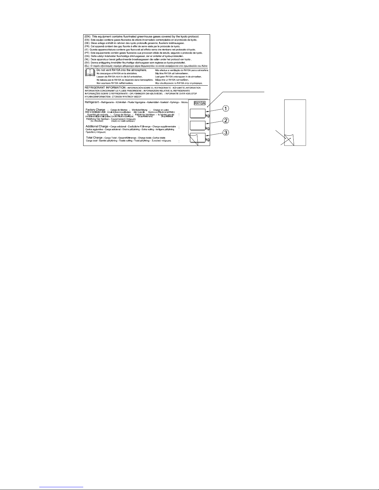
From 4th July 2007 and following Regulation EC Nº 842/2006 on Certain Fluorinated Greenhouse gases, it is mandatory to ll in the label attached to the unit
with the total amount of refrigerant charged on the installation.
Do not vent R410A/R407C into the atmosphere: R410A & R407C are uorinated greenhouse gases covered by the Kyoto protocol global warming potential
(GWP) R410A/R407C: = 1975/1652.5.
Page 6
English
Instructions to ll in the "F-Gas Label":
1.- Fill in the Label with indelible ink the refrigerant amounts: - Factory Charge, - Additional Charge & - Total Charge.
2.- Stick the Protection Plastic Film on the F-Gas Label (delivered in a plastic bag with the Manual). To see Figure nº 2.
Figure 1. F-Gas Label with Protection Plastic Film Figure 2. Protection Plastic Film
Protection Plastic Film
Adhesive Surface
Peel-off Paper
Page 7

MODELS CODIFICATION
Important note: Please, check, according to the model name, which is your air conditioner type,
how it is abbreviated and referred to in this instruction manual. This Installation and Operation
Manual is only related to Indoor Units FSN(H)(2/3/4)(E)(i)(k)(M) combined with Outdoor Units
H(V)NP(1)E, HNCE and RAS-4H(V)RNS3E.
Page 8
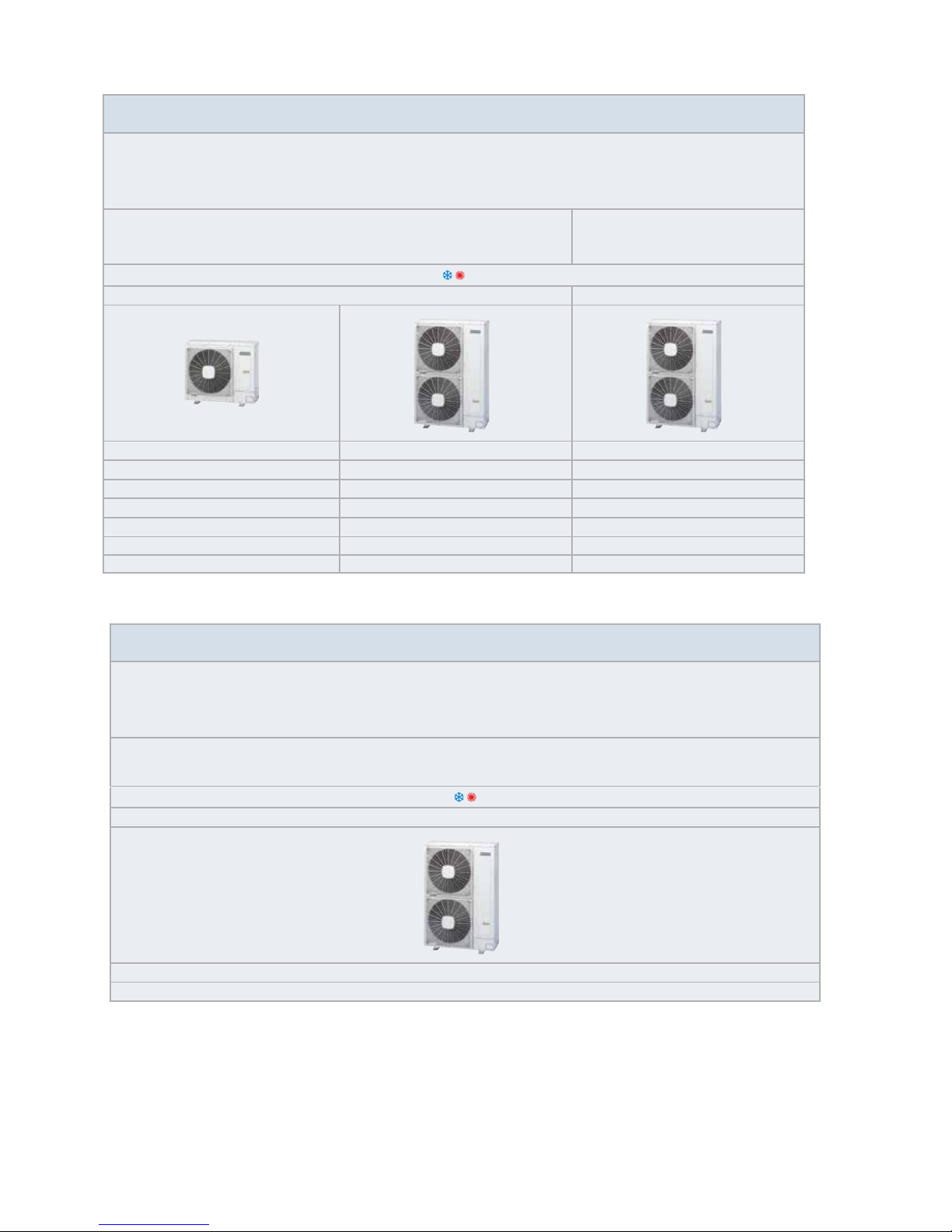
IVX Premium series
OUTDOOR UNIT · UNIDAD EXTERIOR · AUßENEINHEIT · UNITÉ EXTÉRIEURE · UNITÀ ESTERNA ·
UNIDADE EXTERIOR · UDENDRS AGGREGAT · BUITENTOESTEL · UTOMHUSENHET · ΕΞΩΤΕΡΙΚΗ ΜΟΝΑΔΑ
HEAT PUMP MODELS - MODELOS CON BOMBA DE CALOR
WÄRMEPUMPENMODELLE - MODÈLES POMPE À CHALEUR
MODELLI POMPA DI CALORE - MODELOS BOMBA DE CALOR
VARMEPUMPEMODELLER - MODELLEN MET WARMTEPOMP
MODELLER ENDAST FÖR KYLNINGSFUNKTION - ΜΟΝΤΕΛΑ ΜΕ ΑΝΤΛΙΑ ΘΕΡΜΟΤΗΤΑΣ
Single Phase - Monofásico - Einphasig - Monophasé - Monofase
Monofásico - Enfaset - Eenfasig - En fas - Μονοφασικά
Three Phase - Trifásico - Dreiphasig -
Triphasé -Trifase - Trifásico
Trefaset - Driefasig - Trefasig - Tριφασικά
1~ 230V 50Hz 3N~ 400V 50Hz
Unit Unit Unit
RAS-3HVNP1E
RAS-4HVNP1E RAS-4HNP1E
RAS-5HVNP1E RAS-5HNP1E
RAS-6HVNP1E RAS-6HNP1E
RAS-8HNPE
RAS-10HNPE
IVX Standard series
OUTDOOR UNIT · UNIDAD EXTERIOR · AUßENEINHEIT · UNITÉ EXTÉRIEURE · UNITÀ ESTERNA ·
UNIDADE EXTERIOR · UDENDRS AGGREGAT · BUITENTOESTEL · UTOMHUSENHET · ΕΞΩΤΕΡΙΚΗ ΜΟΝΑΔΑ
HEAT PUMP MODELS - MODELOS CON BOMBA DE CALOR
WÄRMEPUMPENMODELLE - MODÈLES POMPE À CHALEUR
MODELLI POMPA DI CALORE - MODELOS BOMBA DE CALOR
VARMEPUMPEMODELLER - MODELLEN MET WARMTEPOMP
MODELLER ENDAST FÖR KYLNINGSFUNKTION - ΜΟΝΤΕΛΑ ΜΕ ΑΝΤΛΙΑ ΘΕΡΜΟΤΗΤΑΣ
Three Phase - Trifásico - Dreiphasig - Triphasé -Trifase - Trifásico
Trefaset - Driefasig - Trefasig - Tριφασικά
3N~ 400V 50Hz
RAS-8HNCE
RAS-10HNCE
Page 9
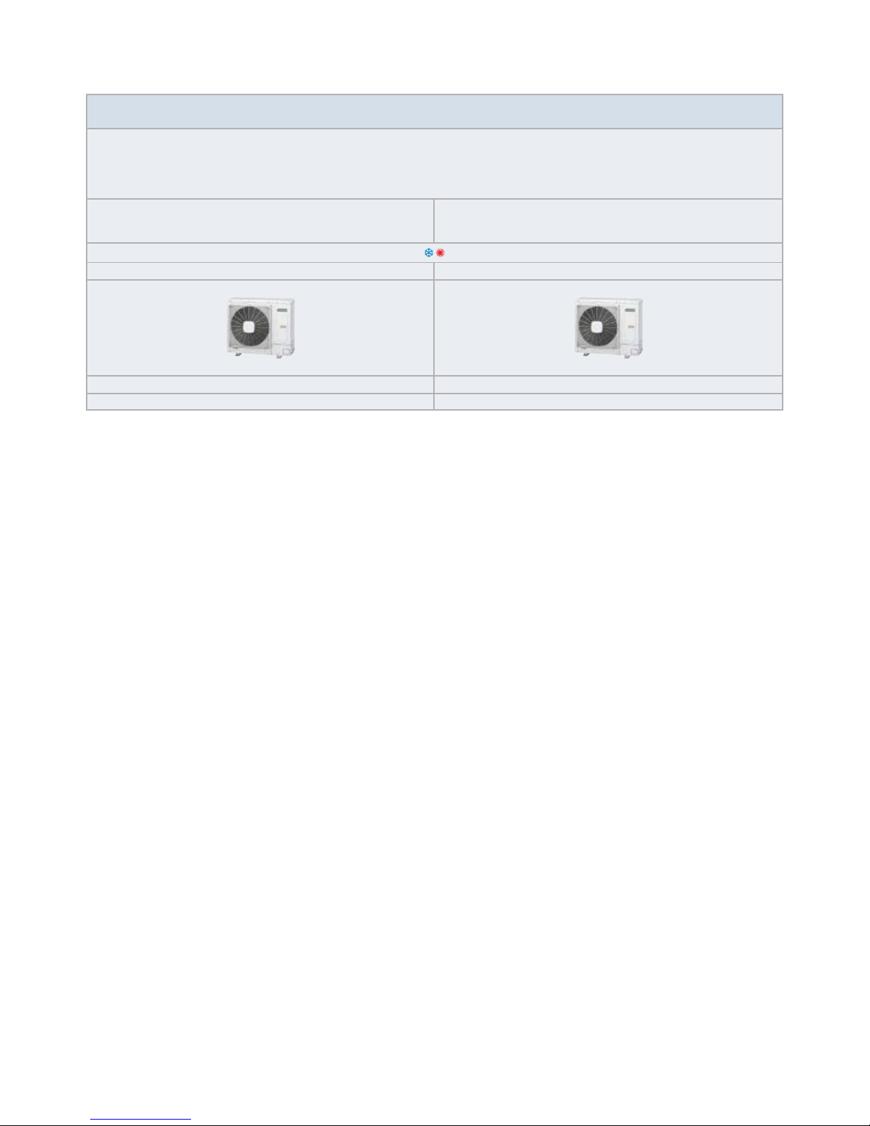
ES series
OUTDOOR UNIT · UNIDAD EXTERIOR · AUßENEINHEIT · UNITÉ EXTÉRIEURE · UNITÀ ESTERNA ·
UNIDADE EXTERIOR · UDENDRS AGGREGAT · BUITENTOESTEL · UTOMHUSENHET · ΕΞΩΤΕΡΙΚΗ ΜΟΝΑΔΑ
HEAT PUMP MODELS - MODELOS CON BOMBA DE CALOR
WÄRMEPUMPENMODELLE - MODÈLES POMPE À CHALEUR
MODELLI POMPA DI CALORE - MODELOS BOMBA DE CALOR
VARMEPUMPEMODELLER - MODELLEN MET WARMTEPOMP
MODELLER ENDAST FÖR KYLNINGSFUNKTION - ΜΟΝΤΕΛΑ ΜΕ ΑΝΤΛΙΑ ΘΕΡΜΟΤΗΤΑΣ
Single Phase - Monofásico - Einphasig - Monophasé - Monofase -
Monofásico - Enfaset - Eenfasig - En fas - Μονοφασικά
Three Phase - Trifásico - Dreiphasig - Triphasé -Trifase -
Trifásico - Trefaset - Driefasig - Trefasig - Tριφασικά
1~ 230V 50Hz 3N~ 400V 50Hz
Unit Unit
RAS-4HVRNS3E RAS-4HRNS3E
Page 10

INDEX ÍNDICE
PART I OPERATION
1. GENERAL INFORMATION
2. SAFETY
3. PRODUCT GUIDE
4. IMPORTANT NOTICE
5. TRANSPORTATION AND HANDLING
6. BEFORE OPERATION
7. REMOTE CONTROLLER
8. AUTOMATIC CONTROLS
9. BASIC TROUBLESHOOTING
PART II INSTALLATION
10. NAME OF PARTS
11. REFRIGERANT CYCLE
12. UNITS INSTALLATION
13. REFRIGERANT PIPING & REFRIGERANT CHARGE
14. DRAIN PIPING
15. ELECTRIC WIRING
16. TEST RUNNING
17. SAFETY SUMMARY & CONTROL DEVICE SETTING
18. TROUBLESHOOTING
1ª PARTE: FUNCIONAMIENTO
1. INFORMACIÓN GENERAL
2. SEGURIDAD
3. GUÍA DEL PRODUCTO
4. AVISO IMPORTANTE
5. TRANSPORTE Y MANIPULACIÓN
6. ANTES DEL FUNCIONAMIENTO
7. CONTROL REMOTO
8. CONTROLES AUTOMÁTICOS
9. RESOLUCIÓN DE PROBLEMAS BÁSICOS
2ª PARTE: INSTALACIÓN
10. NOMBRE DE LAS PIEZAS
11. CICLO DE REFRIGERANTE
12. INSTALACIÓN DE LAS UNIDADES
13. TUBERÍA Y CARGA DE REFRIGERANTE
14. TUBERÍA DE DESAGÜE
15. CABLEADO ELÉCTRICO
16. PRUEBAS DE FUNCIONAMIENTO
17. RESUMEN DE SEGURIDAD Y AJUSTE DE
LOS DISPOSITIVOS DE CONTROL
18. RESOLUCIÓN DE PROBLEMAS
INHALTSVERZEICHNIS INDEX
TEIL I – BETRIEB
1. ALLGEMEINE INFORMATIONEN
2. SICHERHEIT
3. PRODUKTÜBERSICHT
4. WICHTIGER HINWEIS
5. TRANSPORT UND BEDIENUNG
6. VOR DEM BETRIEB
7. FERNBEDIENUNG
8. AUTOMATISCHE STEUERUNG
9. GRUNDLEGENDE FEHLERBESEITIGUNG
TEIL II – INSTALLATION
10. TEILEBEZEICHNUNG
11. KÜHLKREISLAUF
12. GERÄTEINSTALLATION
13. KÄLTEMITTELROHRE UND KÄLTEMITTELMENGE
14. ABFLUSSLEITUNGEN
15. KABELANSCHLUSS
16. TESTLAUF
17. SICHERHEITSÜBERSICHT UND EINSTELLUNG
DER STEUERGERÄTE
18. FEHLERBEHEBUNG
PARTIE I – FONCTIONNEMENT
1. INFORMATIONS GÉNÉRALES
2. SÉCURITÉ
3. GUIDE DU PRODUIT
4. REMARQUES IMPORTANTES
5. TRANSPORT ET MANIPULATION
6. AVANT L’UTILISATION
7. TÉLÉCOMMANDE
8. CONTRÔLES AUTOMATIQUES
9. DÉPANNAGE DE BASE
PARTIE II – INSTALLATION
10. NOMENCLATURE DES PIÈCES
11. CYCLE FRIGORIFIQUE
12. INSTALLATION DES UNITÉS
13. TUYAUTERIE DU FLUIDE FRIGORIGÈNE
ET CHARGE DU FLUIDE FRIGORIGÈNE
14. TUYAUTERIE D’ÉVACUATION DES CONDENSATS
15. CÂBLAGE ÉLECTRIQUE
16. TEST DE FONCTIONNEMENT
17. SOMMAIRE DES DISPOSITIFS DE SÉCURITÉ
& RÉGLAGE DES ORGANES DE CONTRÔLE
18. DEPANNAGE
INDICE ÍNDICE
PARTE I FUNZIONAMENTO
1. INFORMAZIONI GENERALI
2. SICUREZZA
3. GUIDA DEL PRODOTTO
4. NOTA IMPORTANTE
5. TRASPORTO E MOVIMENTAZIONE
6. PROCEDURA PRELIMINARE
7. CONTROLLO REMOTO
8. CONTROLLI AUTOMATICI
9. RISOLUZIONE DEI PROBLEMI MINORI
PART II INSTALLAZIONE
10. NOMENCLATURA DEI COMPONENTI
11. CICLO DI REFRIGERAZIONE
12. INSTALLAZIONE DELLE UNITÀ
13. LINEA DEL REFRIGERANTE E CARICA
DI REFRIGERANTE
14. LINEA DI DRENAGGIO
15. COLLEGAMENTI ELETTRICI
16. COLLAUDO DI PROVA
17. PRECAUZIONI PER LA SICUREZZA E IMPOSTAZIONI
DEI DISPOSITIVI DI CONTROLLO
18. RISOLUZIONE DEI PROBLEMI
PARTE I FUNCIONAMENTO
1. INFORMAÇÃO GERAL
2. SEGURANÇA
3. GUIA DO PRODUTO
4. NOTA IMPORTANTE
5. TRANSPORTE E MANUSEAMENTO
6. ANTES DE ARRANCAR A UNIDADE
7. CONTROLO REMOTO
8. CONTROLOS AUTOMÁTICOS
9. RESOLUÇÃO DE PROBLEMAS BÁSICOS
PARTE II INSTALAÇÃO
10. NOME DAS PEÇAS
11. CICLO DE REFRIGERAÇÃO
12. INSTALAÇÃO DAS UNIDADES
13. TUBAGEM E CARGA DE REFRIGERANTE
14. TUBAGEM DE ESGOTO
15. LIGAÇÕES ELÉCTRICAS
16. PROVA DE FUNCIONAMENTO
17. SUMÁRIO DE SEGURANÇA E AJUSTE
DE DISPOSITIVO DE CONTROLO
18. RESOLUÇÃO DE PROBLEMAS
Page 11
INDHOLDSFORTEGNELSE INHOUDSOPGAVE
DEL I - BETJENING
1. GENEREL INFORMATION
2. SIKKERHED
3. PRODUKTVEJLEDNING
4. VIGTIG MEDDELELSE
5. TRANSPORT OG HÅNDTERING
6. FØR DRIFT
7. FJERNBETJENING
8. AUTOMATISK BETJENING
9. BASIS FEJLFINDING
DEL II- MONTERING
10. NAVNE PÅ DELE
11. KØLEKREDSLØB
12. MONTERING AF ENHEDER
13. KØLERØRSYSTEM OG PÅFYLDNING AF
KØLEMIDDEL
14. AFLØBSRØR
15. ELEKTRISK LEDNINGSFØRING
16. TESTKØRSEL
17. OVERSIGT OVER INDSTILLINGER FOR
SIKKERHEDS- OG KONTROLENHEDER
18. FEJLFINDING
DEEL I BEDIENING
1. ALGEMENE INFORMATIE
2. VEILIGHEID
3. PRODUCTGIDS
4. BELANGRIJKE MEDEDELING
5. TRANSPORT EN HANTERING
6. VOORDAT U HET SYSTEEM IN GEBRUIK NEEMT
7. AFSTANDSBEDIENING
8. AUTOMATISCHE BESTURING
9. ELEMENTAIRE PROBLEMEN OPLOSSEN
DEEL II INSTALLATIE
10. NAMEN VAN ONDERDELEN
11. KOUDEMIDDELCYCLUS
12. INSTALLATIE VAN DE UNITS
13. KOELMIDDELLEIDINGEN & KOELMIDDEL VULLEN
14. AFVOERLEIDING
15. ELEKTRISCHE BEDRADING
16. PROEFDRAAIEN
17. VEILIGHEIDSSAMENVATTING &
BESTURINGSINRICHTING
18. PROBLEMEN OPLOSSEN
INNEHALLSFÖRTECKNING ΕΥΡΕΤΗΡΙΟ
DEL I ANVÄNDNING
1. ALLMÄN INFORMATION
2. SÄKERHET
3. PRODUKTGUIDE
4. VIKTIG ANMÄRKNING
5. TRANSPORT OCH HANTERING
6. FÖRE DRIFT
7. FJÄRRKONTROLL
8. AUTOMATIK KONTROLLANORDNING
9. GRUNDLÄGGANDE FELSÖKNING
DEL II INSTALLATION
10. DELARNAS NAMN
11. KYLMEDIETS CYKEL
12. INSTALLATION AV ENHETER
13. KYLRÖR & PÅFYLLNING AV KYLMEDIUM
14. DRÄNERINGSRÖR
15. ELEKTRISKA KABLAR
16. PROVKÖRNING
17. SÄKERHETSSAMMANFATTNING OCH
SÄKERHETSINSTÄLLNINGAR
18. FELSÖKNING
ΜΕΡΟΣ Ι – ΛΕΙΤΟΥΡΓΙΑ
1. ΓΕΝΙΚΕΣ ΠΛΗΡΟΦΟΡΙΕΣ
2. ΑΣΦΆΛΕΙΑ
3. ΟΔΗΓΟΣ ΠΡΟΪΟΝΤΟΣ
4. ΣΗΜΑΝΤΙΚΗ ΠΑΡΑΤΗΡΗΣΗ
5. ΜΕΤΑΦΟΡΆ ΚΑΙ ΧΕΙΡΙΣΜΌΣ
6. ΠΡΙΝ ΤΗ ΛΕΙΤΟΥΡΓΙΑ
7. ΧΕΙΡΙΣΤΗΡΙΟ
8. ΑΥΤΟΜΑΤΕΣ ΛΕΙΤΟΥΡΓΙΕΣ
9. ΑΝΤΙΜΕΤΩΠΙΣΗ ΠΡΟΒΛΗΜΑΤΩΝ - ΒΑΣΙΚΑ
ΜΕΡΟΣ ΙΙ – ΕΓΚΑΤΑΣΤΑΣΗ
10. ΟΝΟΜΑΤΑ ΕΞΑΡΤΗΜΑΤΩΝ
11. ΚΥΚΛΟΣ ΨΥΞΗΣ
12. ΕΓΚΑΤΑΣΤΑΣΗ ΕΣΩΤΕΡΙΚΩΝ ΜΟΝΑΔΩΝ
13. ΣΩΛΗΝΩΣΕΙΣ ΨΥΚΤΙΚΟΥ & ΠΛΗΡΩΣΗ ΜΕ
ΨΥΚΤΙΚΟ ΜΕΣΟ
14. ΣΩΛΗΝΩΣΕΙΣ ΑΠΟΧΕΤΕΥΣΗΣ
15. ΗΛΕΚΤΡΙΚΗ ΚΑΛΩΔΙΩΣΗ
16. ΔΟΚΙΜΑΣΤΙΚΗ ΛΕΙΤΟΥΡΓΙΑ
17. ΣΥΝΟΠΤΙΚΕΣ ΠΡΟΦΥΛΑΞΕΙΣ ΑΣΦΑΛΕΙΑΣ
& ΡΥΘΜΙΣΕΙΣ ΣΥΣΚΕΥΩΝ ΕΛΕΓΧΟΥ
18. ΑΝΤΙΜΕΤΩΠΙΣΗ ΠΡΟΒΛΗΜΑΤΩΝ
EN English Original version
ES Español Versión traducida
DE Deutsch Übersetzte Version
FR Français Version traduite
IT Italiano Versione tradotta
PT Português Versão traduzidal
DA Dansk Oversat version
NL Nederlands Vertaalde versie
SV Svenska Översatt version
EL ΕΛΛΗΝΙΚΑ Μεταφρασμένη έκδοση
Page 12

Page 13
General information
1
PMML0317A rev.1 - 11/2013
ENGLISH
PART I - OPERATION
1.2 ENVIRONMENT-FRIENDLY UNITS
1 GENERAL INFORMATION
1.1 GENERAL NOTES
No part of this publication may be reproduced, copied, led or
transmitted in any shape or form without the permission of
HITACHI Air Conditioning Products Europe, S.A.U.
Within the policy of continuous improvement of its products,
HITACHI Air Conditioning Products Europe, S.A.U. reserves the
right to make changes at any time without prior notication and
without being compelled to introducing them into products subsequently sold. This document may therefore have been subject to
amendments during the life of the product.
HITACHI makes every effort to offer correct, up-to-date documentation. Despite this, printing errors cannot be controlled by
HITACHI and are not its responsibility.
As a result, some of the images or data used to illustrate this
document may not refer to specic models. No claims will be accepted based on the data, illustrations and descriptions included
in this manual.
This range of HITACHI outdoor units uses environmentally-friendly R410A gas refrigerant, and the RoHS and Greed Dot regulations are applied throughout the manufacturing and installation
process to reect HITACHI’s awareness of environmental respect
and commitment.
2 SAFETY
2.1 APPLIED SYMBOLS
During normal air conditioning system design work or unit installation, greater attention must be paid in certain situations requiring particular care in order to avoid injuries an damage to the unit,
the installation or the building or property.
Situations that jeopardise the safety of those in the surrounding
area or that put the unit itself a risk will be clearly indicated in this
manual.
To indicate these situations, a series of special symbols will be
used to clearly identify these situations.
Pay close attention to these symbols and to the messages following them, as your safety and that of others depends on it.
DA N G ER
• Thetextfollowingthissymbolcontainsinformationand
instructionsrelatingdirectlytoyoursafetyandphysical
wellbeing.
• Nottakingthese instructionsintoaccountcouldleadto
serious,veryseriousorevenfatalinjuriestoyouandothersintheproximitiesoftheunit.
In the text following the danger symbol you can also nd information on safe procedures during unit installation.
CA U T IO N
• The text following this symbol contains information and instructions relating directly to your safety and physical wellbeing.
• Not taking these instructions into account could lead to minor
injuries to you and others in the proximities of the unit.
• Not taking these instructions into account could lead to unit
damage.
In the text following the caution symbol you can also nd information on safe procedures during unit installation.
NO T E
• The text following this symbol contains information or instructions that may be of use or that require a more thorough explanation.
• Instructions regarding inspections to be made on unit parts or
systems may also be included.
Page 14
2
Product guide
PMML0317A rev.1 - 11/2013
3 PRODUCT GUIDE
DA N G ER
• Donotpourwaterintotheindoororoutdoorunit.These
productsareequippedwithelectricalparts.Ifwatercontactswithelectricalcomponentsthenitwillcauseaseriouselectricalshock.
• Donottouchoradjustsafetydevicesinsidetheindooror
outdoorunits.Ifthesedevicesaretouchedoradjusted,it
maycauseaseriousaccident.
• Donot open the service cover or access the indoor or
outdoorunitswithoutdisconnectingthemainpowersupply.
• IncaseofreTurnOFFthemainswitch,putoutthere
atonceandcontactyourservicecontractor.
CA U T IO N
• Do not use any sprays such as insecticide, lacquer, hair spray
or other ammable gases within approximately one (1) meter
from the system.
• If circuit breaker or fuse is often activated, stop the system
and contact your service contractor.
• Do not make service or inspections tasks by yourself. This
works must be performed by qualied service person.
• Do not put any strange material (sticks, etc...) into the air inlet
and outlet. These units have high speed rotating fans and it is
dangerous that any object touches them.
• Refrigerant leakage can cause difculty with breathing due to
insufcient air.
• This appliance must be used only by adult and capable people, having received the technical information or instructions
to handle properly and safely this appliance.
• Children should be supervised to ensure that they do not play
with the appliance.
NO T E
It is recommended to ventilate the room every 3 or 4 hours.
2.2 ADDITIONAL INFORMATION ABOUT SAFETY
3.1 CLASSIFICATION OF IVX OUTDOOR UNITS MODELS
Unit type (Outdoor unit): RAS
Position-separating hyphen (xed)
Compressor power (HP): 3, 4, 5, 6, 8, 10
H = Heat pump
V = Single phase unit (1~ 230V 50Hz)
- = Three phase unit (3N~ 400V 50Hz)
N = R410A refrigerant
P: Premium series
C: Standard series
- = Series 0
1 = Series 1
E = Made in Europe
XXX – XX H (X) N X (X) X
3.2 CLASSIFICATION OF ES OUTDOOR UNITS MODELS
Unit type (Outdoor unit): RAS
Position-separating hyphen (xed)
Compressor power (HP): 4
H = Heat pump
V = Single phase unit (1~ 230V 50Hz)
- = Three phase unit (3N~ 400V 50Hz)
R = Inverter system
N = R410A refrigerant
S = ES series
Series
E = Made in Europe
XXX – XX H (X) R N S 3 X
Page 15
Important notice
3
PMML0317A rev.1 - 11/2013
ENGLISH
4 IMPORTANT NOTICE
CA U T IO N
This unit is designed for commercial and light industrial application. If installed in house hold appliance, it could cause electromagnetic interference.
Start-up and Operation: Check to ensure that all the stop valves
are fully opened and no obstacle exists at the inlet/outlet sides
before start-up and during the operation.
Maintenance: Periodically check the high pressure side pressure. If the pressure is higher than the maximum allowable pressure, stop the system and clean the heat exchanger or remove
the cause.
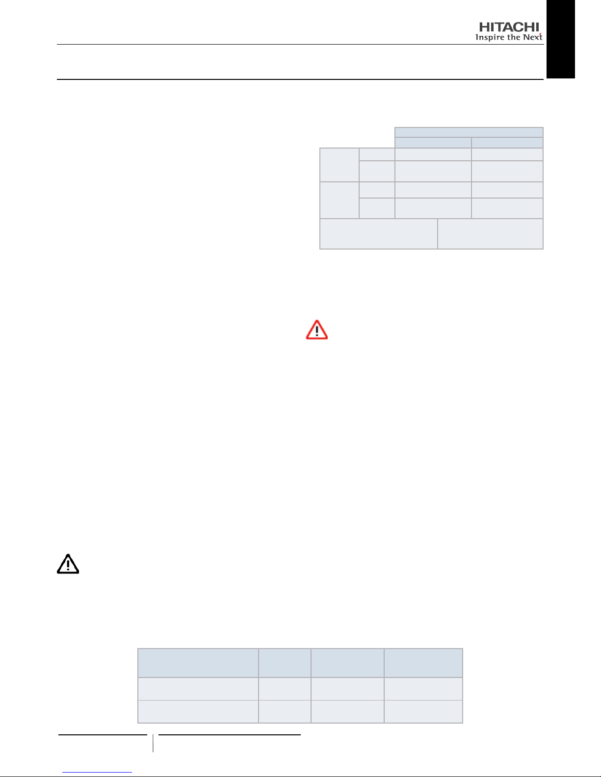
Maximum Allowable Pressure and High Pressure Cut-out Value:
Outdoor Unit Model Refrigerant
Maximum Allowable
Pressure (MPa)
High Pressure Switch
Cut-out Value (MPa)
RAS-(3-10)H(V)NP(1)E
RAS-(8-10)HNCE
R410A 4.15 4.00 ~ 4.10
RAS-4H(V)RNS3E R410A 4.15 4.00 ~ 4.10
• Verify, in accordance with the manuals which appear in the
outdoor and indoor units, that all the information required for
the correct installation of the system is included. If this is not
the case, contact your distributor.
• HITACHI pursues a policy of continuing improvement
in design and performance of products. The right is therefore
reserved to vary specications without notice.
• HITACHI cannot anticipate every possible circumstance that
might involve a potential hazard.
• This air conditioner has been designed for standard air conditioning for human beings. For use in other applications, please
contact your HITACHI dealer or service contractor.
• No part of this manual may be reproduced without written permission.
• If you have any questions, contact your service contractor of
HITACHI.
• This manual gives a common description and information
for this air conditioner which you operate as well as for other
models.
• Check and make sure that the explanations of each part of
this manual correspond to your air conditioner model.
• Refer to the models codication to conrm the main characteristics of your system.
• Signal words (DANGER, WARNING and CAUTION) are used
to identify levels of hazard seriousness. Denitions for identifying hazard levels are provided below with their respective
signal words.
• It is assumed that this unit will be operated and serviced by
English speaking people. If this is not the case, the customer
should add safety, caution and operating signs in the native
language of the personal.
• This air conditioner has been designed for the following temperature. Operate the air conditioner within this range:
Temperature
Maximum Minimum
Cooling
Mode
Indoor 32°C DB/23°C WB 21°C DB/15°C WB
Outdoor 46 ºC DB (*) -5 °C DB
Heating
Mode
Indoor 27 °C DB 15 °C DB
Outdoor 15 °C WB -20 °C WB (**)
DB: Dry Bulb Temperature
WB: Wet Bulb Temperature
(*) 43ºC RAS-4H(V)RNS3E
(**) -10ºC RAS-4H(V)RNS3E
• These operations modes are controlled by the remote control
switch.
• This manual should be considered as a permanent part of the
air conditioner. This manual gives a common description and
information for this air conditioner which you operate as well
as for other models.
DA N G ER
Pressure Vessel and Safety Device: This air conditioner
is equipped witha highpressure vesselunder PED(Pressure Equipment Directive). The pressure vessel has
been designed and tested before shipment according to
PED.Also, in order to prevent the system from an abnormal pressure, a high pressure switch, which needs no
eld adjustment, is utilized in the refrigeration system.
Therefore, this air conditioner is protected from abnormal
pressures. However, if abnormally high pressure is appliedto the refrigerationcycle including thehigh pressure
vessel(s),itwillresultinseriousinjuryordeathduetoexplosionofthepressurevessel.Donotapplyapressurehigher
thanthefollowingpressuretothesystem,bymodifyingor
changingthehighpressureswitch.
Page 16

4
Transportation and handling
PMML0317A rev.1 - 11/2013
NO T E
The label for the vessel under PED are attached on the high pressure vessel. The pressure vessel capacity and vessel category
are indicated on the vessel.
Location of High Pressure Switch
Compressor
NO T E
The high pressure switch is indicated on the electrical wiring diagram in the outdoor unit as PSH connected to printed circuit
board (PCB1) in the outdoor unit
Structure of High Pressure Switch
Contact Point Pressure Detected
Connected to the electrical wire
DA N G ER
• Donotchangethehigh-pressureswitchlocallyorchange
thehighpressurecut-outsetvaluelocally.Ifchanged,it
willcauseseriousinjuryordeathduetoexplosion.
• Donotattempttoturnservicevalverodbeyonditsstop.
6 BEFORE OPERATION
CA U T IO N
• Supply electrical power to the system for approximately 12 hours
before start-up or a long shutdown. Do not start the system immediately after power supply, it may cause a compressor failure
because the compressor is not heated well.
• When the system is started after a shutdown longer that approximately 3 months, it is recommended to check the system
by your service contractor.
• Turn OFF the main switch when the system is to be stopped
for a long period of time: If the main switch is not turned OFF,
electricity will be used, because the oil heater is always energised during compressor stopping.
• Make sure that the outdoor unit is not covered with snow or
ice. If covered, remove it by using hot water (approximately
50°C). If the water temperature is higher that 50 °C, it will
cause damage to plastic parts.
7 REMOTE CONTROLLER
It is advisable to use PC-ART or PC-ARF remote controller (both optional). For more information about it installation and operation,
please refer to its corresponding Installation and Operation Manuals.
5 TRANSPORTATION AND HANDLING
When hanging the unit, ensure a balance of the unit, check safety
and lift it up smoothly
Do not remove any packing materials.
Hang the unit under packing condition with two ropes.
For safety reasons ensure that the outdoor unit is lifted smoothly
and does not lean
Model
Gross
Weight
(kg)
RAS-3HVNP1E 77
RAS-(4-6)H(V)NP1E 116
RAS-4H(V)RNS3E 78
Model
Gross
Weight
(kg)
RAS-8HNPE
152
RAS-8HNCE
RAS-10HNPE
154
RAS-10HNCE
RAS-3HVNP1E RAS-(4-6)H(V)NP1E
RAS-4H(V)RNS3E RAS-(8-10)HNPE
RAS-(8-10)HNCE
0.7 -1.0 m
> 60º
Page 17

Automatic controls
5
PMML0317A rev.1 - 11/2013
ENGLISH
8 AUTOMATIC CONTROLS
The system is equipped with the following functions.
Three minute guard
The compressor remains off for at least 3 minutes once it has
stopped. If the system is started within approximately 3 minutes
after it has stopped, the RUN indicator is activated. However, the
cooling operation or the heating operation remains off and does
not start until after 3 minutes has elapsed.
Operation may stop for 6 minutes maximum to protect compressor.
Frost prevention during cooling operation
When the system is operated in a low temperature room, the
cooling operation may be changed to fan operation for a while to
avoid frost formation on the indoor heat exchanger.
Automatic restart after power failure
If the power supply is interrupted for short periods of time (up to
2 seconds) the Remote Control switch will retain the settings and
the unit will restart when the power is restored. If Automatic Restart is required after periods of lost power supply in excess of 2
seconds please contact your distributor (optional function).
Slow air control during heating operation
Can be setting than when the compressor is stopped while the
thermostat is OFF, or the system is performing the automatic defrosting operation, the fan speed is set at the slow position.
Automatic defrosting cycle
When the heating operation is stopped by pressing RUN/STOP
switch, frosting on the outdoor unit is checked and the defrosting
operation may be performed for the maximum of 10 minutes.
Prevention of overload operation
When the outdoor temperature is too high during heating operation, heating operation is stopped due to activation of the outdoor
thermistor until the temperature becomes low.
Hot start during heating operation
To prevent cold air discharge, the fan speed is controlled from
the slow position to the set position according to the discharge air
temperature. At this time the lover is xed horizontally.
9 BASIC TROUBLESHOOTING
CA U T IO N
• When water leakage from the indoor unit occurs, stop the operation and contact your contractor
• When you smell or white smoke occurs from the unit, stop the
system and contact your contractor.
This is not abnormal
• Sound from deforming Part
During system starting or stopping, and abrading sound might
be heard. However, this is due to thermal deformation of plastic
parts. It is not abnormal.
• Refrigerant Flow Sound
While the system is being started or stopping, sound from the
refrigerant ow may be heard.
• Smells from Indoor Unit
Smell adheres on indoor unit after a long period of time. Clean the
air lter and panels or make a good ventilation.
• Steam from Outdoor Heat Exchanger
During defrosting operation, ice on the outdoor heat exchanger is
melted, resulting in making steam.
• Dew on Air Panel
When the cooling operation continues for a long period of time
under high humidity conditions (higher than 27°C DB/80% R.H.),
dew can form on the air panel.
• Dew on Cabinet
When the cooling operation continues for a long period of timer
(higher than 27°C DB/80% R.H.), dew can form on the cabinet.
• Sound for the indoor unit heat exchanger
During the cooling operation, a sound may be heard from the indoor unit heat exchanger due to water freezing or melting.
No operation
Check whether the SET TEMPERATURE is set at the correct
temperature.
Not cooling well or heating well
- Check for obstruction of air ow of the outside or inside
units.
- Check if too much heat source exists in the room.
- Check if the air lter is clogged with dust.
- Check to see if the doors or windows are opened or not.
- Check if the temperature condition is not within the operating range.
Abnormal swing louver’s position
Check if the four louver’s position at the air outlet are in same
position.
If trouble still remains...
If the trouble still remains even after checking the above items,
contact your service contractor and inform the following data:
- Unit Model Name
- Content of Trouble
- Alarm Code no. on Liquid Crystal Display
NO T E
Except for a long period of shutdown, keep the main switch ON,
since the oil heater is energised when the compressor is stopped.
Page 18

6
Name of parts
PMML0317A rev.1 - 11/2013
PART II - INSTALLATION
10 NAME OF PARTS
10.1 Example of RAS-3HVNP1E / RAS-4H(V)RNS3E
No. Part Name
1 Compressor
2 Accumulator
3 Heat exchanger
4 Propeller fan
5 Fan motor
6 Strainer
7 Distributor
8 Reversing valve
9
Micro-computer control expansion
valve
10 Solenoid valve for hot gas
11 Stop valve for gas line
No. Part Name
12 Stop valve for liquid line
13 Check Joint
14 Electrical box
15 High pressure switch for protection
16
Sensor for refrigerant pressure (RAS-
3HVNP1E only)
17 Pressure switch for control
18 Silencer
19 Crankcase heater
20 Vibration absorbing rubber (3pcs.)
21 Air outlet
22 Air inlet
7T143458
Page 19

Name of parts
7
PMML0317A rev.1 - 11/2013
ENGLISH
10.2 Example of RAS-(4-6)H(V)NP1E
No. Part Name
1 Compressor
2 Heat exchanger
3 Propeller fan (2pcs.)
4 Fan motor (2pcs.)
5 Strainer
6 Distributor
7 Reversing Valve
8
Micro-computer control expansion
valve
9 Solenoid valve
10 Check valve
11 Stop valve for gas line
12 Stop valve for liquid line
No. Part Name
13 Receiver
14 Accumulator
15 Check joint
16 Electrical box
17 High pressure switch for protection
18 Sensor for refrigerant pressure
19 Pressure switch for control
20 Silencer
21 Crankcase heater
22 Vibration absorbing rubber (4pcs.)
23 Air outlet
24 Air inlet
7T143459
Page 20

8
Refrigerant cycle
PMML0317A rev.1 - 11/2013
11 REFRIGERANT CYCLE
Example of RAS-4H(V)NP1E:
D
C
B
A
E
7S138311
F
Mark Part name
1 Compressor
2 Heat exchanger
3 Accumulator
4 Receiver
5 Micro-computer control expansion valve
6 Reversing valve
7 Solenoid valve for gas bypass
8 Strainer
9 Distributor
10 Check joint
11 High pressure switch for protection
12 Sensor for refrigerant pressure
13 Stop valve for gas line
14 Stop valve for liquid line
15 Check valve
16 Silencer
17 Pressure switch for control
Example of RAS-4H(V)RNS3E:
A
B
C
D
F
F
E
7S136195
No. Part name
1 Compressor
2 Heat exchanger
3 Accumulator
4 Micro-Computer control expansion valve
5 Reversing valve
6 Solenoid valve for gas bypass
7 Strainer
8 Distributor
9 Check joint
10 High pressure switch for protection
11 Pressure switch for control
12 Stop valve for gas line
13 Stop valve for liquid line
14 Silencer
R410A 4.15 MPa
Refrigerant ow
or cooling
Refrigerant ow
for heating
Connection by
are nut
Connection by
welding
Gas refrigerant
Leakage test
pressure
Mark Part name
A Gas line refrigerant piping connection
B Liquid line refrigerant piping connection
C Outdoor unit
D Ambient thermistor
E Discharge gas thermistor
F Pipe thermistor
Page 21

Units installation
9
PMML0317A rev.1 - 11/2013
ENGLISH
12 UNITS INSTALLATION
12.1 OUTDOOR UNITS INSTALLATION
12.1.1 Installation space
(Unit: mm)
Blocked in Inlet Side
Upper Side Open
Single Installation Multiple Installation (Two units or more)
200 or more of the back space is acceptable when the right and
left sides are open.
Dimensions in ( ) shows numbers especially for RAS-3HVNP1E.
Allow 100 mm of space between units. Leave open both right and left sides.
Dimensions in ( ) shows numbers especially for RAS-3HVNP1E.
Be sure to use the fan direction guide. Leave open both right and
left sides.
Be sure to use the fan direction guide. Allow 100 mm of space between units.
Leave open both right and left sides.
CA U T IO N
• Transport the products as close to the installation location as
practical before unpacking.
• Do not put any material on the products.
• Apply four lifting wires on to the outdoor, when lifting it by
crane
CA U T IO N
• Install the outdoor unit with sufcient clearance around it for
operation and maintenance as shown in the next gures.
Install the outdoor unit where good ventilation is available
• Do not install the outdoor unit where is a high level of oil mist,
salty air or sulphurous atmosphere.
• Install the outdoor unit as far as practical (being at least 3
meters) from electromagnetic wave radiator (such as medical
equipment).
• For cleaning, use noninammable and nontoxic cleaning liquid. Use of inammable agent may cause explosion or re.
• Work with sufcient ventilation, for working in an enclosed
space may cause oxygen deciency. Toxic gas may be produced when cleaning agent is heated to high temperature by,
e.g., being exposed to re.
• Cleaning liquid shall be collected after cleaning.
• Pay attention not to clamp cables when attaching the service
cover to avoid electric shock or re.
CA U T IO N
• Keep clearance between the units of more than 100mm, and
avoid obstacles that may hamper air intake, when installing
more than one units together.
• Install the outdoor unit in the shade or not exposed to direct sunshine or direct radiation from high temperature heat
source.
• Do not install the Outdoor Unit in a space where a seasonal
wind directly blows to the Outdoor fan.
• Check to ensure that the foundation is at, level and sufciently strong.
• Install the unit in a restricted area not accessible by the general public
• Aluminium ns have very sharp edges. Pay attention to the
ns to avoid injury.
Page 22

10
Units installation
PMML0317A rev.1 - 11/2013
Blocked in Inlet Side
Upper Side Blocked
Single Installation Multiple Installation (Two units or more)
100 mm or more of the side space is acceptable on the service
cover side.
Allow 100 mm of space between units. Leave open both right and left sides..
Leave open both right and left sides.
Be sure to use the fan direction guide. Allow 100 mm of space between units.
Leave open both right and left sides.
No more than 2 units for multiple installation.
The length A is as shown in the following table:
L A
0 < L ≤ 1/2H 600 or greater
1/2H < L≤ H 1400 or greater
When L > H use a base for outdoor unit to make L ≤ H.
Close the base not to allow the outlet air bypassed.
Outlet Side Blocked
Upper Side Open
Single Installation Multiple Installation (Two units or more)
Allow 100 mm of space between units. Both right and left sides shall be open.
Be sure to use the fan direction guide. Leave open both right and
left sides.
Be sure to use the fan direction guide. Allow 100 mm of space between units.
Leave open both right and left sides.
No more than 2 units for multiple installation.
The length A is as shown in the following table:
L A
0 < L ≤ 1/2H 600 or greater
1/2H < L≤ H 1400 or greater
When L > H use a base for outdoor unit to make L ≤ H.
Close the base not to allow the outlet air bypassed.
Page 23

Units installation
11
PMML0317A rev.1 - 11/2013
ENGLISH
12.1.2 Installation place provision
Concrete Foundation
1 Foundation could be on at and is recommended be 100-300
mm higher than ground level.
2 Install a drainage around foundation for smooth drain
3 When installing the outdoor unit x the unit by anchor bolts
of M10.
4 When installing the unit on a roof or a veranda, drain water
sometimes turns to ice on a cold morning. Therefore, avoid
draining in an area that people often use because it is slippery.
* Space for downward piping space
Nº Description
Outdoor Unit
Cut this portion of bolt If not, it’s difcult to remove Service Cover
Mortar Hole (Ø100xDepth 150)
Anchor Bolt M10 (Ø12.5 Hole)
Drainage (Wide 100xDepth 150)
Drainage
Vibration-proof rubber
NO T E
When the mark * dimension is secured, piping work from bottom
side is easy without interference of foundation.
5 The whole of the base of the outdoor unit should be installed
on a foundation. When using vibration-proof mat, it should
also be positioned the same way. When installing the outdoor
unit on a eld supplied frame, use metal plates to adjust the
frame width for stable installation as shown in below gure.
70 mm
Base width of outdoor unit
Outdoor unit is
unstable
Frame
60mm
Frame with (Field supplied)
INCORRECT
CORRECT
Outdoor unit is
stable
70 mm
Base width of outdoor unit
Frame
100mm or more
Metal plate
Recommended Metal Plate Size
- (Field-Supplied) Material: Hot-Rolled Mild Steel
- Plate (SPHC) Plate Thickness: 4.5 T
Page 24

12
Units installation
PMML0317A rev.1 - 11/2013
Fix Unit to the wall
1. Fix the Unit onto the wall as the gure indicates. (eld supplied stay)
2. Ensure the foundation so that avoid
the deforming and noise.
3. In case of prevention from vibration
transfer to the building, use rubber
Mat.
Rubber Material
(Field Supplied)
Mark Dimension
Model
RAS-3HVNP1E
RAS-4H(V)RNS3E
RAS-(4-10)H(V)NP(1)E
A (mm) 529 1109
Suspended unit
1. Suspend the unit as the drawing
indicates.
2. Ensure that wall can resist the Outdoor unit weight indicated in specication label plate.
3. It is recommended to select each foot
support to bear the full weight of
the unit (in order to consider stress
fatigue applied when unit is working
too).
Wall bracket (*)
Anchor Bolts (*)
(*) Field supplied
CAUTION
Pay attention to the following for installation:
• Installation shall ensure that outdoor
unit will not incline, vibrate, make noise
or fall down by a blast of wind or in an
earthquake. Calculate quake-resistance
strength to ensure that installation is
strong enough against falling. Fix the unit
with wires (eld supplied) when installing
in a location without walls or windbreak
and likely exposed to a blast of wind.
• To use a vibration-proof mat, x four places
to the front and back.
Installing location where the unit will be exposed to strong wind.
Follow the instructions below to install
on the rooftop or a location without surrounding buildings, where strong wind is
expected against the product.
1. Choose a location where the outlet or
inlet side of the product will not be
exposed to strong wind.
2. When the outlet is exposed to strong
wind:
Direct strong wind may cause lack
of air ow and adversely affect to the
operation.
CAUTION
Excessive strong wind against the outdoor unit
outlet may cause inverse rotation and damage
the fan and motor.
Page 25

Units installation
13
PMML0317A rev.1 - 11/2013
ENGLISH
Air ow guide wind guard and snow protection hood
RAS-3HVNP1E/RAS-4H(V)RNS3E
Optional parts Model
Air ow guide AG-335A
1 Air ow guide
2 Wind Guard
3 Snow protection hood
Wind guard WSP-335A
Snow protection
hood
Zinc plate
Air outlet ASG-NP335F
Air inlet of rear side ASG-NP80B
Air inlet of side face ASG-NP80L
Stainless plate
(SUS304)
Air outlet ASG-NP335F52
Air inlet of rear side ASG-NP160BS2
Air inlet of side face ASG-NP160LS2
1. Fixing screw (Accessories).
2. Rear suction hood
3. Wire rope (Optional. For
overturning protection)
4. Air discharge grille
5. Left suction hood
6. Air discharge hood
A. Left side
B. Front side
C. Rear side
RAS-(4-6)H(V)NPE / RAS-(8-10)HN(P/C)E
Optional parts Model
Air ow guide AG-335A X 2
1 2
3
1 Air ow guide
2 Wind Guard
3 Snow protection hood
Wind guard WSP-335A X 2
Snow
protection
hood
Zinc plate
Air outlet ASG-NP335F X 2
Air inlet of rear side ASG-NP280B
Air inlet of side face ASG-NP280L
Stainless plate
(NSSC 180)
Air outlet ASG-NP335FS 2X 2
Air inlet of rear side ASG-280BS2
Air inlet of side face ASG-NP280LS2
1. Left suction hood
2. Fixing screw (Accessories)
3. Rear suction hood Upper
side
4. Wire rope (Optional. For
overturning protection)
5. Rear suction hood Lower
side
6. Air discharge hood
7. Air discharge grille
A. Front side
B. Left side
C. Rear side
Page 26

14
Refrigerant piping & refrigerant charge
PMML0317A rev.1 - 11/2013
13 REFRIGERANT PIPING & REFRIGERANT CHARGE
13.1 PIPING MATERIALS
1 Prepare locally-supplied copper pipes.
2 Select the piping size with the correct thickness and correct
material which can have sufcient pressure strength.
3 Select clean copper pipes. Make sure there is no dust and
moisture inside. Blow the inside of the pipes with oxygen free
nitrogen to remove any dust and foreign materials before connecting pipes.
NO T E
• A system with no moisture or oil contamination will give maximum performance and lifecycle compared to that of a poorly
prepared system. Take particular care to ensure all copper
piping is clean and dry internally.
• There is no refrigerant in the cycle of the indoor unit.
CA U T IO N
• Cap the end of the pipe when pipe is to be inserted through
a hole.
• Do not put pipes on the ground directly without a cap or vinyl
tape at the end of the pipe
• If piping installation is not completed until next day or over
a longer period of time, braze off the ends of the piping and
charge with oxygen free nitrogen through a Schrader valve
type access tting to prevent moisture and particle contamination.
• Do not use insulation material that contains NH3 because it
can damage cooper pipe material and can be a source of future leakage.
• Completely insulate both refrigerant gas piping and liquid piping between the indoor unit(s) and the outdoor unit.
• If not insulated, dew will ocur on the piping surface
13.2 SUSPENSION OF REFRIGERANT PIPING
Suspend the refrigerant piping at certain points and prevent the
refrigerant piping from touching the weak part of the building such
as wall, ceiling, etc…
(If touched, abnormal sound may occur due to the vibration of the
piping. Pay special attention in case of short piping length).
1~15m
Indoor unit
Fire-Proof
Section Treatment
Do not x the refrigerant piping directly with the metal ttings (The
refrigerant piping may expand and contract).
Some examples for suspension method are shown below.
For Suspending
Heavies
For piping along
the wall
For instant
installation work
Page 27

Refrigerant piping & refrigerant charge
15
PMML0317A rev.1 - 11/2013
ENGLISH
13.3 PIPING CONNECTION FOR OUTDOOR UNIT
1 The pipes can be connected from 4 directions. Make holes in
the piping cover or cabinet for taking out pipes. Take the piping cover away from the unit, and make holes by cutting along
the guideline at the rear of the cover or punching with a driver.
Remove the burr with a cutter, and place a insulation (eld
supplied) to protect cables and pipes.
(picture as example)
Nº Description
Rear side piping work
Pipe Cover
Right side piping work
Bottom side piping work (Knock out hole)
Front side piping work
Piping work
Stop Valve
Removing Direction for Service Cover
CA U T IO N
Notes to open/close the service cover:
• Remove the screws following the instructions to the above
gure.
• Slowly press down the cover.
NOTE
Hold the cover with a hand to remove screws as the cover may
fall down.
Service cover
Hook (three places): two fans
Hook (two places): one fan
(picture as example)
For the front and side piping
Front piping hole
Side piping hole
To use racking or conduit tubes, check the size and remove
part following the slit.
NO T E
Place insulation (eld supplied) to protect cables and pipes from
being damaged by plate edges.
For the downward piping
Gas piping
Knock-out hole
Bottom base
Cables
Liquid piping
NO T E
Cables shall not contact directly to the pipes.
For the rear side piping
Rear Cover
NO T E
Remove the rear pipe cover under the rear cover and remove
part following the slit.
Page 28

16
Refrigerant piping & refrigerant charge
PMML0317A rev.1 - 11/2013
2 Mount the piping cover in order to avoid water entering into
the unit. Seal the holes where pipes and wires are inserted, by
using a insulation (eld-supplied).
3 If the eld-supplied piping is connected with stop valves di-
rectly, it is recommended use a tube bender.
4 Check to ensure that the stop valves are closed completely
before connecting pipes.
5 Connect the eld supplied refrigerant pipes to the indoor unit
and outdoor unit. Apply the oil thinly at the seat are nut and
pipe before tightening.
The required tightening torque is as follows:
Pipe Size Tightening Torque (Nm)
Ø 6.35 mm (1/4) 20
Ø 9.52 mm (3/8) 40
Ø 12.70 mm (1/2) 60
Ø 15.88 mm (5/8) 80
Ø 19.05 mm (3/4) 100
6 After connecting the refrigerant piping, seal the open space
between knockout hole and refrigerant pipes by using insulation material.
Unit
Side
Nº Description
Insulation Material
Insulation Material
Field Supplied
Insulation Material
7 Operation of stop valve should be performed according to the
gure below.
Close before shipment
Outdoor unit stop valve
Spindle Type Ball Type
Liquid
RAS-(4-10)H(V)NP(1)E
RAS-(8/10)HNCE
Liquid and Gas
RAS-3HVNP1E
RAS-4H(V)RNS3E
Gas
RAS-(4-10)H(V)NP(1)E
RAS-(8/10)HNCE
(a)
Spindle valve
Flare nut
Cap
Check joint for service port
Tightening Torque (Nm)
Liquid valve 7-9
40
10HP: 60
33-42
14-18
Gas valve 9-11
80
8/10HP: 100
3HP: 33-42
4/5/6HP:
P=20-25
S=33-42
8/10HP:20-25
Spindle Type Ball Type
(a) (b)
Nº Description Remarks
Cap
Allen wrench Hex 4 mm
Refrigerant Piping Field Supplied
Flare nut
Refrigerant Pressure To Outdoor Unit
Seat Surface Fully closed position
Check Joint Only the charging those can be connected
Charge port cap
O-Ring Rubber
Spindle valve
Open – Counterclockwise
Close – Clockwise
«
Shaft
¬
Pin
Stopper
(a)
Closed
This valve is opened or closed with rotating 90
degrees at the ball valve part. Rotate the shaft
until the pin touches the stopper. Do not apply the
extra force. Use a slotted screwdriver to control
the shaft. Do not leave the ball valve partly open
(b)
Opened
Do not apply two spanners
at this position. If applied,
leakage will occur.
Stop valve
(Spindle type)
Flare nut
Use two spanners
here for pipe connection
Do not work with
two spanners
here.
Refrigerant
leakage shall
occur
Position to apply
spanners
Don not apply
two spanners
work here
Spindle type Ball type
CA U T IO N
• At the test run, fully open the spindle and ball stop valve.
• If not fully opened, the devices will be damaged.
• Do not attempt to turn service valve rod beyond its stop.
• Do not loosen the stop ring. If the stop ring is loosened, it is
dangerous since the spindle will hop out.
• An excess or a shortage of refrigerant is the main cause of
trouble to the units. Charge the correct refrigerant quantity
according to the description of label at the inside of service
cover.
• Check for refrigerant leakage in detail. If a large refrigerant
leakage occurs, it will cause difculty with breathing or harmful
gases would occur if a re was being used in the room.
Page 29

Refrigerant piping & refrigerant charge
17
PMML0317A rev.1 - 11/2013
ENGLISH
Evacuation and refrigerant charge
- Connect the gauge manifold using charging hoses with a
vacuum pump or a nitrogen cylinder to the check joints of
the liquid line and the gas line stop valve.
- Check for any gas leakage at the are nut connection, by
using nitrogen gas to increase the pressure at 4.15 MPa
for outdoor units inside of the eld-supplied piping.
- Operate the vacuum pump for 1 to 2 hours until the pressure decreases lower than a pressure of 756 mmHg in
vacuum.
- For charging refrigerant, connect the gauge manifold using charging hoses with a refrigerant charging cylinder to
the check joint of the liquid line stop valve.
- Charge the proper quantity of refrigerant according to
the piping length (Calculate the quantity of the refrigerant
charge).
- Fully open the gas line stop valve, and slightly open the
liquid line stop valve.
- Charge refrigerant by opening the gauge manifold valve.
- Charge the required refrigerant within the difference range
of ±0.5kg by operating the system in cooling.
- Fully open the liquid line stop valve after completing refrigerant charge.
- Continue cooling operation for more than 10 minutes to
circulate the refrigerant.
Thermal insulation
Gas line
Cover the are nut and union
of the piping connection with
thermal insulation
Liquid line
Liquid stop valve
Gas stop valve
Nitrogen tank
(For air Tight test
& Nitrogen blow
during brazing)
Vacuum cylinder
Ma nif old
gauge
Outdoor unit
Insulate the liquid pipe for
prevention of the capacity
decrease according to the
ambient air conditions and
the dewing on the pipe surface by the low pressure
Example of Evacuation and Refrigerant Charge.
13.4 REFRIGERANT PIPING LENGTH
The refrigerant piping between the indoor unit and the outdoor unit should be designed using the following table.
Piping length specication for header branch
(Example for header branch)
1 indoor unit system
(O.U. IVX Series from 3 to 10 HP
and O.U. ES Series 4 HP)
2 indoor units system
(O.U. IVX Series from 3 to 10 HP
and O.U. ES Series 4 HP)(*)
3 indoor units system
(O.U. IVX Series from 4 to 10 HP)(*)
4 indoor units system (O.U. IVX Series from 4 to 10 HP)(*)
(pictures are as example)
(*) Connections including Indoor Units 8 and 10 HP are not possible
Page 30

18
Refrigerant piping & refrigerant charge
PMML0317A rev.1 - 11/2013
Maximum refrigerant piping length
IVX Premium series
(m)
Outdoor Unit 3HP 4HP 5HP 6HP 8HP 10HP
Maximum piping Length be-
tween the outdoor unit and
the farthest indoor unit
Actual Length (L) 50 75 100
Equivalent Length (EL) 70 95 125
Total piping length
2 units (A+B+C) 60 85 100 115
3 units (A+B+C+D) -- 95 100 130
4 units
(A+B+C+D+E+F+G+)
-- 95 100 145
Maximum piping line
after rst branch
2 and 3 units (B, C, D) 10 15
4 units
(B+D, B+E, C+F, C+G)
-- 10 15
Main piping length A A > B, C, D, E, F, G
Maximum height difference
Outdoor / Indoor (H)
(Outdoor Unit is Higher / Lower.)
30 / 20
Maximum height difference Indoor / Indoor 10
Maximum height difference:
branch pipe/Indoor (2, 3 and 4 units system)
branch pipe/branch pipe (4 units system)
3
(B-C) / (B-D) / (C-D) / (C+G)-(B+E) / (C+G)-(B+D)
(C+F)-(B+E) / (C+F)-(B+D)
< 8
IVX Standard series
(m)
Outdoor Unit 8HP 10HP
Maximum piping Length
between the outdoor unit
and the farthest indoor
unit
Actual Length (L) 100
Equivalent Length (EL) 125
Total piping length
2 units (A+B+C) 100 115
3 units (A+B+C+D) 100 130
4 units
(A+B+C+D+E+F+G+)
100 145
Maximum piping line
after rst branch
2 and 3 units (B, C, D) 15
4 units
(B+D, B+E, C+F, C+G)
15
Main piping length A A > B, C, D, E, F, G
Maximum height difference
Outdoor / Indoor (H)
(Outdoor Unit is Higher / Lower.)
30 / 20
Maximum height difference Indoor / Indoor 3
Maximum height difference:
branch pipe/Indoor (2, 3 and 4 units system)
branch pipe/branch pipe (4 units system)
3
(B-C) / (B-D) / (C-D) / (C+G)-(B+E) / (C+G)-(B+D)
(C+F)-(B+E) / (C+F)-(B+D)
< 8
Page 31

Refrigerant piping & refrigerant charge
19
PMML0317A rev.1 - 11/2013
ENGLISH
ES series
(m)
Outdoor Unit 4HP
Maximum piping Length between the
outdoor unit and the indoor unit
Actual Length (L) 50
Equivalent Length (EL) 70
Maximum height difference Outdoor / Indoor (H)
(Outdoor Unit is Higher / Lower)
30 /20
Maximum height difference Indoor / Indoor 0.5
Maximum total piping length Twin (A + B + C) 60
Maximum piping line after branch Twin (B, C) 10
(B-C) < 8
NO T E
• The liquid piping and the gas piping must be of the same piping length and run along the same route.
• Install the branch piping as much as possible near the indoor units
• Install Multikits at the same horizontal level.
Example for line branch (Only allowed for IVX series)
OU 3 HP 4 HP 5 HP 6 HP 8 HP 10 HP
IU
quantity
allowed
IVX Premium 2 -3 2 - 5 2 - 6 2 - 8
IVX Standard -- - - - 2 - 4
1 2 4 53
(picture is as example)
Connections including Indoor Units 8 and 10 HP are not possible
Maximum refrigerant piping length (Line branch system)
IVX Premium series
(m)
Outdoor Unit 3HP 4HP 5HP 6HP 8HP 10HP
Maximum piping length between
the outdoor unit and the farthest
indoor unit
Actual Length (L1) 50 75 100
Equivalent Length (EL) 70 95 125
Maximum piping length from rst branch to each indoor unit (L2) 20 30 40
Maximum piping length from branch to indoor unit (L3) 10 15
Maximum piping length L4 + (L3
1
+L32+L33....) 60 95 100 145
Maximum height difference
Outdoor / Indoor (H)
(Outdoor Unit is Higher / Lower.)
30 / 20
Maximum height Difference Indoor / Indoor 10
Maximum height difference:
Branch pipe/Indoor
Branch pipe/branch pipe
3
Page 32

20
Refrigerant piping & refrigerant charge
PMML0317A rev.1 - 11/2013
IVX Standard series
(m)
Outdoor Unit 8HP 10HP
Maximum piping length
between the outdoor unit
and the farthest indoor
unit
Actual Length (L1) 100
Equivalent Length (EL) 125
Maximum piping length from rst branch to each indoor unit (L2) 25
Maximum piping length from branch to indoor unit (L3) 15
Maximum piping length L4 + (L3
1
+L32+L33....) 100 145
Maximum height difference
Outdoor / Indoor (H)
(Outdoor Unit is Higher / Lower.)
30 / 20
Maximum height Difference Indoor / Indoor 3
Maximum height difference:
Branch pipe/Indoor
Branch pipe/branch pipe
3
13.4.1 Refrigerant piping size and multikit/distributor
Select the piping connection sizes according to the following procedures:
• Between outdoor unit and branch pipe: Select the same pipe connection size as the pipe size of the outdoor unit.
• Between branch pipe and indoor unit: Select the same pipe connection size as the pipe size of the indoor unit.
1 indoor unit system
(mm)
Outdoor Unit HP
Pipe Size (L)
Gas Liquid
2 / 2.5 Ø12.70 Ø6.35
3 - 6 Ø15.88 Ø9.52
8 Ø25.40 Ø9.52
10 Ø25.40 Ø12.70
2 indoor units system
(mm)
Outdoor Unit HP
Pipe Size (A) Branch pipe
Gas Liquid IVX Series ES Series
2 / 2.5 Ø12.70 Ø6.35 TE-03N1 -
3 / 4 Ø15.88 Ø9.52
3HP:TE-03N1
4HP:TE-04N1
4 HP: TE-04N1
5 / 6 Ø15.88 Ø9.52 TE-56N1- -
8 Ø25.40 Ø9.52 TE-08N -
10 Ø25.40 Ø12.70 TE-10N -
(mm)
Indoor Unit capacity
Pipe Size (B, C)
Gas Liquid
≤ 1.5 HP Ø12.70 Ø6.35
1.8/2.0HP Ø15.88 Ø6.35
≥ 2.3 HP Ø15.88 Ø9.52
Connections including Indoor Units 8 and 10 HP are not
possible
Page 33

Refrigerant piping & refrigerant charge
21
PMML0317A rev.1 - 11/2013
ENGLISH
3 indoor units system (Only allowed for IVX series)
(mm)
Outdoor Unit HP
Pipe Size (A) Header Branch
Gas Liquid IVX Series
4 / 5 / 6 Ø15.88 Ø9.52 TRE-46N1
8 Ø25.40 Ø9.52 TRE-812N1
10 Ø25.40 Ø12.70 TRE-812N1
(mm)
Indoor Units capacity
Pipe Size (B, C, D)
Gas Liquid
≤ 1.5 HP Ø12.70 Ø6.35
1.8/2.0HP Ø15.88 Ø6.35
≥ 2.3 HP Ø15.88 Ø9.52
Connections including Indoor Units 8 and 10 HP are
not possible
4 indoor units (Only allowed for IVX series)
1
2
1 2
3
4
(mm)
Outdoor
Unit HP
Pipe Size (A)
Branch line
(1) In case that total pipe length (A+B+D or A+B+E or
A+C+F or A+C+G) exceeds of 70m in 8 HP unit, please
use a Ø12.7 pipe as a liquid pipe.
(2) When is used Multi-kit model QE-812N1 it is not necesary the multi.kit 2.
F
G
Gas Liquid IVX Series
4 / 5 / 6 Ø15.88 Ø9.52
4HP: TE-04N1
5/6HP: TE-56N1
8 Ø25.40 Ø9.52
(1)
TE-08N
QE-812N1
(2)
10 Ø25.40 Ø12.70
TE-10N
QE-812N1
(2)
(mm)
Branch line
Indoor Unit
capacity
Pipe Size (D,E,F,G)
Branch pipe after total
capacity of indoor units
1+2 or 3+4
Pipe Size
(B,C)
IVX Series
Gas Liquid
Gas Liquid ≤ 1.5 HP Ø12.70 Ø6.35
≤ 1.5 HP Ø12.70 Ø6.35 TE-03N1 1.8/2.0 HP Ø15.88 Ø6.35
from 1.8 to 2.0 HP Ø15.88 Ø6.35 TE-03N1 ≥ 2.3 HP Ø15.88 Ø9.52
≥ 2.3 HP Ø15.88 Ø9.52
<4: TE-03N1
=4HP: TE-04N1
≥ 5HP: TE-56N1
Connections including Indoor Units 8
and 10 HP are not possible
Page 34

22
Refrigerant piping & refrigerant charge
PMML0317A rev.1 - 11/2013
Line branch system (Only allowed for IVX series)
A
B
D
c
(mm)
Multi Kit
Model A
Multi Kit
Model B
Outdoor
Unit HP
Pipe Size (C, D) (L4)
IVX Series
Gas Liquid
3 / 4 / 5 / 6 Ø15.88 Ø9.52 E-102SN(2/3) E-102SN(2/3)
8 Ø25.40 Ø9.52
(1)
E-162SN(2/3) E-102SN(2/3)
10 /12 Ø25.40 Ø12.70 E-162SN(2/3) E-102SN(2/3)
(1) In case that pipe length exceeds 70m in 8 HP, please use a
Ø12.7 pipe as a liquid pipe.
Indoor Unit capacity
Pipe Size (L3)
Gas Liquid
≤ 1.5 HP Ø12.70 Ø6.35
from 1.8 to 2.0 HP Ø15.88 Ø6.35
≥ 2.3 HP Ø15.88 Ø9.52
Connections including Indoor Units 8 and 10 HP are not possible
13.4.2 System Installation (examples)
Height Difference Between Indoor Units and Distributor
It is recommended to install all indoor units at the same height.
When the height difference between the indoor units due to building construction is necessary, this should be less than the value
indicated in the gure
ื
10m (IVX-P)
3m (IVX-C)
ืืืื
20m
ืืืื
30m
IU1
IU4
IU3
IU2
OU1
OU1
ื
3m
ื
3m
ื
3m
ื
3m
ื
3m
ื
3m
(ื
6m)
O.U higher
O.U lower
10m (IVX-P)
3m (IVX-C)
ื
ื
ืื
ืื
ืื
ืื
ืื
ืื
High difference O.U/IU
O.U higher ≤30m
O.U lower ≤20m
Installing Distributor
1 Install the Distributor supplied by HITACHI on request.
A tee can not be installed instead of a branch pipe.
2 Installing the distributor
Fix the branch pipe horizontally to the pillar, wall or ceiling. Piping must not be xed rigidly to the wall as thermal expansion and
contraction can cause pipe fracture.
Horizontal
To Indoor
Unit
To Outdoor unit
Vertical
To Indoor unit
Fixing the branch pipe to
the surface of pillar or wall
Horizontal
Horizontal
Fixing the branch pipe to
ceiling or beam
(pictures as example)
NO T E
Fix the piping from outside of insulation or inserting absorber between the pipe and a xing metal.
3 Correct position of distributor (available also for quad instal-
lation)
• This is the correct position:
G r ea t e r
than 0.5 m
Main pipe
Refrigerant direction
Up
Branch pipe
Main pipe
Refrigerant direction
Down
• This is wrong position.
Main pipe
Refrigerant direction
Branch pipe
Branch pipe
Refrigerant direction
Branch pipe
Main pipe
(pictures as example)
Page 35

Refrigerant piping & refrigerant charge
23
PMML0317A rev.1 - 11/2013
ENGLISH
4 Correct position of Triple Branch Pipe (Standard series only).
• Install the header horizontally
Sample: Triple Branch pipe
Gas piping
Liquid piping
13.4.3 Brazing work
CA U T IO N
• Use nitrogen gas for blowing during pipe brazing. If oxygen,
acetylene or uorocarbon gas is used, it will cause an explosion or poisonous gas.
• A lot of oxidation lm will occur inside of tubes if no nitrogen
gas blowing is performed during brazing work. This lm will
be ecked off after operation and will circulate in the cycle,
resulting in clogged expansion valves, etc. This will cause bad
inuence to the compressor.
• Use a reducer valve when nitrogen gas blowing is performed
during brazing. The gas pressure should be maintained within
0.03 to 0.05 Mpa. If a excessively high pressure is applied to
a pipe, it will cause an explosion.
13.4.4 Refrigerant charge
CA U T IO N
• Do not charge OXYGEN, ACETYLENE, or other ammable
and poisonous gases into the refrigerant because an explosion can occur. It is recommended that oxygen free nitrogen
be charged for these types of tests cycle when performing
a leakage test or an airtight test. These types of gases are
extremely dangerous,
• Insulate the unions and are-nuts at the piping connection
part completely.
• Insulate the liquid piping completely to avoid a decrease of
performance; if not, it will cause sweating on the surface of
the pipe.
• Charge refrigerant correctly. Overcharging or insufcient
charging could cause a compressor failure.
• Check for refrigerant leakage in detail. If a large refrigerant
leakage occurred, it would cause difculty with breathing or
harmful gases would occur if a re were being used in the
room.
• If the are nut is tigthened too hard, the are nut may crack
after a long time and cause refrigerant leakage.
13.6 REFRIGERANT CHARGING QUANTITY
When the pressure is measured, use the check joint of gas stop
valve (A), and use the check joint of liquid piping (B) in the gure
below.
At that time, connect the pressure gauge according to the following table because of high pressure side and low pressure side
changes by operation mode.
Cooling
Operation
Heating
Operation
Check Joint for Gas Stop Valve “A” Low Pressure High Pressure
Check Joint for Piping “B” High Pressure Low Pressure
Check Joint for Liquid Stop Valve “C”
Exclussive for Vacuum Pump
and Refrigerant Charge
NO T E
Be careful that refrigerant and oil do not splash to the electrical
parts at removing the charge hoses.
C
B
A
The gas stayed at O-ring
sc r e w p ar t i s o p en e d
and may make soun d
whe n remov ing the cap.
Ho we ver , it is no t g as
leakage.
13.5 CAUTION OF THE PRESSURE BY CHECK JOINT
Outdoor Units has been charged with refrigerant for 30m of actual
piping length. An additional refrigerant charged is required in systems with actual piping length longer than 30m.
1 Determine an additional refrigerant quantity according to the
following procedure, and charge it into the system.
2 Record the additional refrigerant quantity to facilitate service
activities thereafter.
CA U T IO N
• When charging refrigerant accurately measure refrigerant to
be charged.
• Overcharging or undercharging of refrigerant can cause compressor trouble
• In case of actual piping length less than 5 m, consult your
distributor.
Page 36

24
Refrigerant piping & refrigerant charge
PMML0317A rev.1 - 11/2013
13.6.1 Refrigerant charge before shipment (W0 (kg))
W0 is the outdoor unit refrigerant charge before shipment explained before, and it’s shown in the following table:
IVX Premium series
Model
Refrigerant charge
before shipment
(W0 (kg))
Additional
refrigerant
charge (P)
(g/m)
Maximum
additional
charge
(kg)
RAS-3HVNP1E 2.3 40 1.2
RAS-4HVNP1E 4.1 60 3.9
RAS-5HVNP1E 4.2 60 3.9
RAS-6HVNP1E 4.2 60 3.9
RAS-4HNP1E 4.1 60 3.9
RAS-5HNP1E 4.2 60 3.9
RAS-6HNP1E 4.2 60 3.9
RAS-8HNPE 5.7 (1) 10.3
RAS-10HNPE 6.2 (1) 12.1
(1) need to be calculate
IVX Standard series
Outdoor unit
Refrigerant charge
before shipment
(W0 (kg))
Additional
refrigerant
charge
(g/m)
Maximum
additional
charge
(kg)
RAS-8HNCE 5.7 (1) 10.3
RAS-10HNCE 6.2 (1) 12.1
(1) need to be calculate
ES series
Outdoor unit
Refrigerant charge
before shipment
(W0 (kg))
Additional
refrigerant
charge
(g/m)
Maximum
additional
charge
(kg)
RAS-4HVRNS3E 2.9 40 1.6
RAS-4HRNS3E 2.9 40 1.6
CA U T IO N
• When charging refrigerant, measure the amount precisely.
• Overloading or underloading of refrigerant may cause compressor problems.
• If the actual piping length is less than 5 m consult your dealer.
Additional refrigerant charge calculation method
For all UTOPIA units RAS-(3-6)H(V)NP(1)E and
RAS-4H(V)RNS3E
Use the following formula:: W1 = (L-30) x P
For UTOPIA units RAS-(8-10)HNPE and RAS-(8-10)
HNCE
The additional refrigerant charge for RAS-(8-10)HNPE and RAS(8-10)HNCE units must be calculated by multiplying the total piping length of each diameter per its calculation factor according to
the following table. The result is the additional refrigerant charge
subtracting 1.6 for 8 HP or 2.0 for 10 HP. (Fill the table with the
values)
Pipe size (mm)
Additional refrigerant
charge factor (kg/m)
Ø15.88 x 0.19
Ø12.7 x 0.12
Ø9.52 x 0.065
Ø6.35 x 0.065
Setting of Pipe Length DSW.
DSW2 setting will be required only when the refrigerant pipe
length is shorter than 5 m or longer than 30 m. Pipe length setting
shall be performed as shown below.
(The side in the table below shows the DSW location)
DSW2 on Outdoor PCB1
Factory setting Pipe Length ≤ 5m Pipe Length ≥ 30m
When the refrigerant should be collected into the outdoor unit due
to indoor/outdoor unit relocation, collect the refrigerant as follows:
1 Attach the manifold gauge to the gas stop valve and the liquid
stop valve
2 Turn ON the power source
3 Set the DSW1-1 pin of the outdoor unit PCB at the “ON” side
for cooling operation. Close the liquid stop valve and collect
the refrigerant.
4 When the pressure at lower pressure side (gas stop valve)
indicates -0.01 MPa (-100 mmHg), perform the following procedures immediately.
- Close the gas stop valve.
- Set the DSW1-1 pin at the “OFF” side (To stop the unit
operation).
5 Turn OFF the power source.
CA U T IO N
Measure the low pressure by the pressure gauge and keep it not
to decrease than -0.01 MPa. If the pressure is lower than -0.01
MPa, the compressor may be faulty.
13.7 REFRIGERANT PUMP DOWN
Page 37

Drain piping
25
PMML0317A rev.1 - 11/2013
ENGLISH
14 DRAIN PIPING
15 ELECTRICAL WIRING
1 Ensure that the eld-supplied electrical components (mains
power switches, circuit breakers, wires, connectors and wire
terminals) have been properly selected according to the electrical data indicated. Make sure that they comply with national
and regional electrical codes.
2 Following the Council Directive 2004/108/EC(89/336/EEC),
relating to electromagnetic compatibility, next table indicates:
Maximum permissible system impedance Z
max
at the interface
point of the user’s supply, in accordance with EN61000-3-11
MODEL Z max (Ω) MODEL Z max (Ω)
RAS-3HVNP1E - - RAS-4HVNP1E - RAS-4HNP1E -
RAS-4HVRNS3E 0.27 RAS-4HRNS3E -
RAS-5HVNP1E - RAS-5HNP1E RAS-6HVNP1E - RAS-6HNP1E -
- - RAS-8HNPE -
- - RAS-8HNCE -
- - RAS-10HNPE -
- - RAS-10HNCE -
3 Harmonics situation of each model regarding IEC 61000-3-2
and IEC 61000-3-12 is as follows:
MODELS SITUATION REGARDING
IEC 61000-3-2 AND IEC 61000-3-12
Ssc “xx”
MODELS
Ssc “xx”
(KVA)
Equipment complying with IEC 61000-3-2
(professional use)
RAS-(4-6)HNP1E
RAS-4H(V)RNS3E
Equipment complying with IEC 61000-3-12 RAS-(3-6)HVNP1E -
Installation restrictions may be applied by authorities regarding the power supply in relation
to harmonics
RAS-(8/10)HNPE
RAS-(8/10)HNCE
4 Check to ensure that the power supply voltage is within +/-
10% of the rated voltage.
5 Check to ensure that power supply has an impedance low
enough to warranty not reduce the starting voltage more than
85% of the rated voltage.
6 Check to ensure that the ground wire is connected.
7 Connect a fuse of specied capacity.
NO T E
Check and test to ensure that if there is more than one source of
power supply, that all are turned OFF.
CA U T IO N
• Check to ensure that screws for terminal block are tightly
tightened.
• Check to ensure that the indoor fan and the outdoor fan have
stopped before electrical wiring work or periodical check is
performed.
• Protect the wires, drain pipe, electrical parts, from rats or other
small animals. If not protected, rats may damage unprotected
parts, and at the worst, a re will occur.
• Wrap the accessory packing around the wires, and plug the
wiring connection hole with the seal material to protect the
product from any condensed water and insects.
• Tightly secure the wires with the cord clamp inside the indoor
unit.
• Lead the wires through the knockout hole in the side cover
when using conduit.
• Secure the cable of the remote control switch with the cord
clamp inside the electrical box.
• Electrical wiring must comply with national and local codes.
Contact your local authority in regards to standards, rules,
regulations, etc.
• Check that the ground wire is securely connected.
• Connect a fuse of specied capacity.
DA N G ER
• Donotconnect of adjust any wiring or connectionsunlessthemainpowerswitchisOFF.
• Checkthattheearthwire is securelyconnected,tagged
andlockedinaccordancewithnationalandlocalcodes.
14.1 DRAIN DISCHARGING BOSS
When the base of the outdoor unit is temporarily utilized as a
drain receiver and the drain water in it is discharged, this drain
boss is utilized to connect the drain piping.
Model Applicable Model
DBS-26 All units
Connecting procedure
1 Insert the rubber cap into the drain boss up to the extruded
portions.
2 Insert the boss into the unit base and turn approximately 40
degree counterclockwise.
3 Size of the drain boss is 32 mm (O.D.).
4 A drain pipe should be eld-supplied.
NO T E
Do not use this drain boss set in a cold area, because the drain
water may freeze.
This drain boss is not sufcient to collect all the drain water. If
collecting drain water is completely required, provide a drain-pan
that is bigger than the unit base and install it under the unit with
drainage.
Rubber cap
Drain Boss
Extruded portion
Drain pipe
Drain pipe
Drain hole
of Base
15.1 GENERAL CHECK
Page 38

26
Electrical wiring
PMML0317A rev.1 - 11/2013
The electrical wiring connection for the outdoor unit is
shown in gure below:
RAS-3HVNP1E
RAS-(4-6)HVNP1E
RAS-4HVRNS3E
RAS-4HRNS3E
RAS-(4-10)HNP(1)E
RAS-(8-10)HNCE
Power supply
1~ 230V
Control cable (5V)
Power supply
3N~ 400V
Control cable (5V)
Table for Terminal Connection between units
Wiring System
Units type
Connection of terminals
Power Supply DC inverter
O.U. to O.U.
L1 to L1, L2 to L2, L3 to L3, N to N
I.U. to I.U.
L1 to L1, N to N)
Operating DC inverter
O.U. to I.U. or I.U. toI.U.
1 to1, 2 to 2
Remote Control DC inverter
I.U. to I.U.
A to A, B to B
O.U.: Outdoor Unit; I.U.: Indoor unit
15.2.1 Setting of DIP Switches for Outdoor Unit
Quantity and Position of DIP Switches.
The location is as follows:
RAS-3HVNP1E, RAS-(4-10)H(V)NP(1)E, RAS-(8-10)HNCE
and RAS-4H(V)RNS3E
DSW1: For Test Run
Factory setting
DSW2: Optional Function Setting
Factory setting
Piping length ≤ 5m
Piping lenght ≥ 30m
Control to support existing pipes or
when using Ø19,05 gas pipe (soft-annealed),
switch ON DSW2 pin 4 in the outdoor unit
PCB
Optional function setting mode (The optional
function selection mode become available)
1 2 3 4 5 6
ON
External input/output setting mode (The input
/ output signals selection mode becomes
avaliable).
15.2 ELECTRICAL WIRING CONNECTION FOR OUTDOOR UNITS
Page 39

Electrical wiring
27
PMML0317A rev.1 - 11/2013
ENGLISH
DSW3: Capacity
Factory setting
RAS-3HVNP1E
RAS-4HVNP1E
RAS-4HVRNS3E
RAS-5HVNP1E RAS-6HVNP1E
1 2 3 4 5 6
ON
1 2 3 4 5 6
ON
1 2 3 4 5 6
ON
1 2 3 4 5 6
ON
RAS-4HNP1E
RAS-4HRNS3E
RAS-5HNP1E RAS-6HNP1E
RAS-8HNPE
RAS-8HNCE
RAS-10HNPE
RAS-10HNCE
1 2 3 4 5 6
ON
1 2 3 4 5 6
ON
1 2 3 4 5 6
ON
1 2 3 4 5 6
ON
1 2 3 4 5 6
ON
DSW5: Transmission Setting of End Terminal Resistance
Factory setting
Cancellation
In the case that the outdoor units quantity in the same H-LINK
is 2 or more, set No. 1 pin of DSW5 at “OFF” side from the 2nd
refrigerant group outdoor unit. If only one outdoor unit is used, no
setting is required.
DSW4 / RSW1: Refrigerant Cycle No. Setting
Factory setting
(Setting for the ten digit).
Factory setting
(Setting for the last digit).
0
9
8
7
6
5
4
3
2
1
DSW6: Optional function setting (IVX series only)
For individual operation
(factory setting position)
For IVX series
For simultaneous operation
DSW6: Only for ES series
Factory setting
Example of DSW5 setting
1 2
DSW5
1 2
DSW5
1 2
DSW5
1 2
DSW5
( H-LINK) ( H-LINK)
( H-LINK)
Page 40

28
Electrical wiring
PMML0317A rev.1 - 11/2013
15.3 COMMON WIRING
CA U T IO N
All the eld wiring and electrical components must comply with
local codes.
15.3.1 Electrical wiring between indoor unit and
outdoor unit
• Connect the electrical wires between the indoor unit and the
outdoor unit, as shown below.
• Follow local codes and regulations when performing electrical
wiring.
• If the refrigerant piping and the control wiring are connected to
the units in the same refrigerant cycle.
• Use twist pair wire (more than 0.75 mm²) for operation wiring
between outdoor unit and indoor unit, and operation wiring
between indoor unit and indoor unit.
• Use 2-core wire for the operating line (Do not use wire with
more than 3 cores).
• Use shielded wires for intermediate wiring to protect the units
from noise obstacle at length of less than 300 m and size
complied with local code.
• Open a hole near the connection hole of power source wiring
when multiple outdoor units are connected from one power
source line.
• The recommended breaker sizes are detailed in the Wire size
section.
• In the case that a conduit tube for eld-wiring is not used, x
rubber bushes with adhesive on the panel.
• All the eld wiring and equipment must comply with local and
international codes.
• H-LINK twist pair shielded cable must be grounded in the outdoor unit side.
CA U T IO N
Pay attention to the connection of the operating line. Incorrect
connection may cause the failure of PCB.
Power source from the outdoor IVX unit
to the indoor unit (example)
Independent power source of outdoor IVX unit
and indoor unit (example)
3
3
3
L1 L2 L3 NL1 L2 L3 N
L1 L2 L3 N
No. 0 System
Outdoor unit
No. 0 System
Outdoor unit
Operating Line
(Shielded Pair Cable)
5V (Non-Pole Transmission,
H-LINK System)
Remote Control Switch
(Twisted Shielded Pair
Cable)
Operating Line
(Twisted Shielded
Pair Cable)
5V (Non-Pole Transmission, H-LINK
System)
Indoor Unit
Indoor Unit
Terminal board
Circuit Breaker
Earthleakage Breaker
Field Wiring
Field supplied
Optional Accessory
Remote Control Switch
(Twisted Shielded Pair
Cable)
Indoor Unit
Indoor Unit
Wiring example (IVX series only)
Basic combinations (in the case of twin combination)
1 2
ON
DSW6
1 2
ON
DSW6
1 2
ON
DSW6
Operating line
Operating line Operating line
Remote control
line
Remote control
line
Remote control
line
Individual control
Running ON/OFF individually
Thermo.ON/OFF individually
Individual control
Running ON/OFF simultaneously
Thermo.ON/OFF individually
Simultaneous control
Running ON/OFF simultaneously
Thermo.ON/OFF simultaneously
Page 41

Electrical wiring
29
PMML0317A rev.1 - 11/2013
ENGLISH
15.3.2 Wire size
Connection wiring
Recommended minimum sizes for eld provided wires:
Model Power supply
Power source
cable size
Transmitting
cable size
EN60 335-1 EN60 335-1
All Indoor Units
1~ 230V 50Hz
0.75 mm²
0.75 mm²
RAS-3HVNP1E
4.0 mm²
RAS-(4-6)HVNP1E
6.0 mm
2
RAS-4HVRNS3E
6.0 mm
2
RAS-(4-6)HNP1E
3N~ 400V 50Hz
2.5 mm
2
RAS-4HRNS3E
4 mm
2
RAS-(8-10)HNPE
6.0 mm
2
RAS-(8-10)HNCE
6.0 mm
2
NO T E
• Follow local codes and regulations when selecting eld wires,
Circuit breakers and Earth Leakage breakers
• Use the wires which are not lighter than the ordinary polychloroprene sheathed exible cord (code designation H05RN-F)
Main switch protection
Select the main switches in according to the next table:
Model Power supply
Max. current
(A)
CB (A)
ELB (no.
poles/A/mA)
All Indoor Units 1~ 230V 50Hz 5.0 6 2/40/30
ELB: Earth switch; CB: Circuit braker
IVX Premium series
Outdoor unit
MC
(A)
CB
(A)
ELB
RAS-3HVNP1E
21.5 25
2/40/30
RAS-4HVNP1E
30.5 40
RAS-5HVNP1E
30.5 40
RAS-6HVNP1E
30.5 40
RAS-4HNP1E
14.0 20
4/40/30
RAS-5HNP1E
14.0 20
RAS-6HNP1E
16.0 20
RAS-8HNPE
24.0 30
RAS-10HNPE
24.0 30
IVX Standard series
Outdoor unit
MC
(A)
CB
(A)
ELB
RAS-8HNCE 24.0 30
4/40/30
RAS-10HNCE 24.0 30
ES series
Outdoor unit
MC
(A)
CB
(A)
ELB
RAS-4HVRNS3E 28.0 32 2/40/30
RAS-4HRNS3E 15.0 20 4/40/30
15.3.3 H-LINK II System
NO T E
The H-LINK II system can not be applied to the cycle with the old H-LINK model.
1 Application
The new H-LINK II connecting each indoor unit and outdoor unit for up to 64 refrigerant cycles (up to 160 indoor unit per H-LINKII),
and connecting wires for all indoor units and all outdoor units in series.
2 Specications
- Transmission Wire: 2-Wire.
- Polarity of Transmission Wire: Non-Polar Wire.
- Maximum Outdoor Units To Be Connected: 64 Units per H-LINK II system.
- Maximum Indoor Units To Be Connected: 160 Units per H-LINK II system.
- Maximum Wiring Length: Total 1000m (including CS-NET). In case that the total wiring length is longer than 1000m, contact
the Hitachi dealer.
- Recommended Cable: Twist Pair Cable with Shield, over 0.75mm2 (Equivalent to KPEV-S).
- Voltage: 5V.
NO T E
Do not make a wiring in a loop.
3 Dip Switch Setting of Indoor PCB and Outdoor PCB.
It is required to set dip switches of every indoor unit and outdoor unit.
Page 42

30
Electrical wiring
PMML0317A rev.1 - 11/2013
15.3.4 System installation DIP Switch Setting
Dip Switch Setting of Indoor PCB and Outdoor PCB for H-LINK II
It is required to set dip switches of every indoor unit and outdoor unit and match of the transmission circuit impedance.
• Dip Switch Setting Example:
Cycle nº 0
DSW5
Terminating Resistance
DSW4
Refrigerant Cycle Nº
(Setting for ten digit)
RSW1
Refrigerant Cycle Nº
(Setting for last digit)
Outdoor units
Indoor units
DSW5
Refrigerant Cycle Nº
(Setting for ten digit)
RSW2
Refrigerant Cycle Nº
(Setting for last digit)
DSW6
Indoor unit Address
(Setting for ten digit)
RSW1
Indoor unit Address
(Setting for last digit)
Cycle nº 1
Cycle nº 2
Unit Name of Dip Switch Mark
Setting Before
Shipment
Function
Outdoor Unit
Refrigerant Cycle
DSW4
RSW1
DSW4 RSW1
For setting refrigerant cycle address of Outdoor Unit. Set the DSW4
and RSW1 not to overlap the setting of other Outdoor units in the same
H-LINK system
Terminating Resistance DSW5
For matching impedance of transmission circuit, set the DSW5 according to the quantity of outdoor units in the H-LINK system.
Indoor Unit
Refrigerant Cycle
DSW5
RSW2
DSW5 RSW2
For setting refrigerant cycle address of indoor units. Set the DSW5 and
RSW2 corresponding to the address of outdoor unit in the same refrigerant cycle.
Indoor Unit Address
DSW6
RSW1
DSW6 RSW1
For setting indoor unit address. Set the DSW6 and RSW1 not to overlap
the setting of other indoor units in the same refrigerant cycle. (If not set,
the automatic address function is performed).
Page 43

Test running
31
PMML0317A rev.1 - 11/2013
ENGLISH
16 TEST RUNNING
When installation is completed, perform test run according to the
following procedure, and hand over the system to the customer.
Perform test run regarding indoor units one by one in order, and
conrm that the electrical wiring and the refrigerant piping are
correctly connected.
Test run should be performed according to the Test Run Proce-
dure on next page.
CA U T IO N
Do not operate the system until all the check points have been
cleared:
• Check to ensure that the electrical resistance is more than
1 MΩ, by measuring the resistance between ground and the
terminal of the electrical parts. If not, do not operate the system until the electrical leakage is found and repaired. Do not
impress the voltage on the terminals for transmission 1 and 2.
• Check to ensure that the stop valves of the outdoor unit are
fully opened, and then start the system.
• Check to ensure that the switch on the main power source has
been ON for more than 12 hours, to warm the compressor oil
by the oil heater
Pay attention to the following items while the system is running:
• Do not touch any of the parts by hand at the discharge gas
side, since the compressor chamber and the pipes at the discharge side are heated higher than 90°C.
• DO NOT PUSH THE BUTTON OF THE MAGNETIC
SWITCH(ES), it will cause a serious accident.
• Do not touch any electrical components for more than three
minutes after turning OFF the main switch
• Conrm that the gas line stop valve and the liquid line stop
valve are fully open.
• Conrm that the leakage of the refrigerant does not exist. The
are nuts are sometimes loosened by vibration during transportation.
• Check that the refrigerant piping and the electrical wiring conform to the same system.
• Conrm that the dip switch setting on the printed circuit board
of the indoor units and the outdoor units are correct.
• Check whether or not the electrical wiring of the indoor units
and the outdoor units are connected as shown in the chapter
Electrical Wiring.
CA U T IO N
Conrm that eld-supplied electrical components (main switch
fuse, fuse-free breaker, earth leakage breakers, wires, conduit
connectors and wire terminals) have been properly selected according to the electrical data given in the Technical Catalog of the
unit and ensure that the components comply with national and
local codes.
NO T E
• For more reference check Troubleshooting chapter on Opera-
tion Part.
• For twin, triple and quad check the indoor unit outlet air temperature at test run. If the temperature difference is large
(aprox. 10 deg. or more (cooling) 20 deg. or more (heating)
recheck the refrigerant piping, Installation may have some
problem.
• In the case of anual cooling optional function, cut JP1 out and
set the DSW6-1 to OFF. (Individual control is not available
when anual cooling is selected).
Page 44

32
Test running
PMML0317A rev.1 - 11/2013
16.1 TEST RUN PROCEDURE BY REMOTE CONTROL SWITCH (PC-ART EXAMPLE)
Turn ON the power source of the Indoor and Outdoor Units
Counting
number of
connected
units
05
Operation lamp
Set the TEST RUN mode by remote control switch.
Depress the “MODE” and the “
OK” switches simultaneously
for more than 3 seconds.
a. If “TEST RUN” and the counting number of the connect-
ed units to the remote control switch (for example
“05”)
are indicated on the remote control switch, the connection of remote control cable is correct.→Go to
b.
If no indication appear or the number of the units indicated is smaller than the actual number of the units, some
abnormalities exist.→Go to
Remote Control
Switch Indication
Wrong Portions Inspection Points after Power Source OFF
No indication
The power source of Outdoor Unit is not
turned ON.
The connection of the remote control cable
is incorrect.
1 Connecting Points of Remote Control Cable terminal board of Remote
Control switch and indoor unit.
2 Contact of Terminals of Remote Control Cable
The connecting wires of power supply line
are incorrect or loosened.
3 Connection Order of each Terminal Board
4 Screw Fastening of each Terminal Boards.
Counting number
of connected units
is incorrect
The power source of Outdoor Unit is not
turned ON.
The operating line wiring between indoor
unit and outdoor unit is not connected.
The connection of control cables between
each indoor units are incorrect. (When
one remote control switch controls multiple
units)
5 Dip Switch Setting on Printed Circuit Board
6 Connecting on the PCB
7 This is the same as item 1, 2 , and 3.
Back to
after checking
Select TEST RUNNING MODE by depressing MODE Switch (COOL OR HEAT)
Depress RUN/STOP switch.
The TEST RUN operation will be started. (The 2 hours OFF-TIMER will be set and the TEST RUN operation will be nished after 2 hours unit
operation or by depressing the RUN/STOP switch again).
NOTE
TEST RUN operation ignores the temperature limitation and ambient temperature during heating operation to have a continuous
operation, but the protections are alive. Therefore, the protection may activate when the heating TEST RUN operation is performed
in high ambient temperature.
TEST RUN operation time can be modifyed / increased depressing the time switch in the Remote Control.
If the unit do not start or the operation lamp on the remote control switch is ickered, some abnormalities exist. →Go to
Page 45

Test running
33
PMML0317A rev.1 - 11/2013
ENGLISH
Remote Control
Switch Indication
Unit Condition Wrong Portions
Inspection Points after
Power Source OFF
The operation lamp ickers. (1 time/1 sec.) And
the Unit No. and Alarm
Code “03” icker
The unit does not start.
The power source of Outdoor
Unit in not turned ON.
The connecting wires of operating
line are incorrect or loosened.
1 Connecting Order of each Terminal
Board.
2 Screw fastening of each Terminal
Boards.
NO T E
Recovering method of FUSE for operating circuit. There is a fuse (FUSE4
on Indoor Unit PCB1, EF1 on Outdoor
Unit PCB1) to protect operating circuit on the PCB, when the power lines
are connected to operating lines. If
fuse is melted, operating circuit can
be recovered once by setting the dip
switch on the PCB as shown in
The operation lamp ickers. (1 time/2 sec.)
The unit does not start.
Remote control cable is broken.
Contact of connectors is not
good.
The connection of remote control
cable is incorrect
This is the same as item
1 and 2
Indication of Flicker
except above
The unit does not start, or start once
and then stops
The connection of thermistor or
other connectors are incorrect.
Tripping of protector exists, or
else.
Check by the abnormality mode table in
the Technical Catalogue (Do it by service people).
The operation lamp
Flickers. (1 Time/1s)
Unit No.
00, Alarm
Code and Unit Code
00 icker
The unit does not start.
The connection of the remote
control cable between Indoor
Units is incorrect.
Check by the abnormality mode table in
the Technical Catalog (Do it by service
people).
Back to
after checking
Instructions fot the recovery when the fuse of the transmission
circuit is blown out:
1 Correct the wiring to the terminal board.
2 Set the 1st pin of DSW7 on the indoor unit PCB to ON.
16.2 TEST RUN FROM OUTDOOR UNIT SIDE
The procedure of test run from outdoor unit side is indicated below. Setting of this DIP switch is available with the power source
ON.
Setting of Dip Switch
DSW1
Switch for setting of Serivice Operation and Function
1 Test Run
2 COOL/HEAT
Setting ON: Heat Operation
3 Cooling/Heating for intermediate
season
4 Manual Compressor stop
CA U T IO N
• Do not touch any other electrical parts when operating switches on the PCB
• Do not attach or detach service cover when the power source
for the outdoor unit is ON and the outdoor unit is operated.
• Turn all DIP switches of DSW1 OFF when the test run operation is completed.
Page 46

34
Test running
PMML0317A rev.1 - 11/2013
Operation Dip Switch Setting Operation Remarks
Test Run
Setting of Operation Mode:
Cooling: Set DSW1-2 OFF.
Heating: Set DSW1-2 ON.
Starting Test Run:
Set DSW1-1 ON and the operation is
started after a few ~20 seconds.
Cooling Heating
The indoor unit automatically start to
operate when the test run of the outdoor
unit is set.
The ON/OFF operation can be performed from the remote control switch or
DSW1-1 of the outdoor unit.
Continuous operation during 2 hours
is performed without Thermo-OFF.
NO T E
• TEST RUN operation time can be
increased depressing the time
switch in the Remote Control.
• If is setting DSW1-3 ON, cool-
ing/heating intermediate season
mode is activaded.
• Take care that the indoor units start op-
eration in accord with the test run operation of the outdoor unit.
• The test run is started from the outdoor
unit and stopped from the remote control switch, the test run function of the
remote control switch is cancelled. However, the test run function of the outdoor
unit is not cancelled
• In case that the plural indoor units are
connected with one remote control
switch, all the units start test run operation at the same time, therefore, turn the
power source OFF for the indoor units
not to operate test run. In this case, the
“TEST RUN” indication of the remote
control switch may icker, and this is not
abnormal.
• The setting of DSW1 is not required
for the test run from the remote control
switch.
Manual OFF of
Compressor
Setting:
Compressor Manual OFF:
Set DSW1-4 ON.
Compressor ON:
Set DSW1-4 OFF.
When DSW1-4 is ON during compressor operation, the compressor stops
to operate immediately and the indoor
unit is under the condition of ThermoOFF.
When DSW1-4 is OFF, the compressor starts to operate after the cancellation of 3-minutes guard.
• Do not repeat compressor ON/OFF fre-
quently.
Manual Defrost
Manual Defrost Operation Starts
Press PSW1 for more than 3 seconds
during heating operation, the defrost
operation is started after 2 minutes.This
function is not available within 5 minutes
after starting heating operation
Manual Defrost Operation Finishes
Defrost operation is automatically ended
and the heating operation is started.
Defrost operation is available regardless of frosting condition and total
time of heating operation.
Defrost operation in not performed
when the temperature of outdoor heat
exchanger is higher than 10°C, high
pressure is higher than 3.3 MPa (33kgf/
cm
2
G) or Thermo-OFF.
• Do not repeat defrost operation frequent-
ly.
Page 47

Safety summary & control device setting
35
PMML0317A rev.1 - 11/2013
ENGLISH
17 SAFETY SUMMARY & CONTROL DEVICE SETTING
Compressor Protection
High Pressure Switch:
This switch cuts out the operation of the compressor when the
discharge pressure exceeds the setting.
Fan Motor Protection
When the thermistor temperature is reached to the setting, motor
output is decreased.
The other way, when the temperature becomes lower, limitation
is cancelled.
Model RAS-3HVNP1E
RAS-(4-6)HVNP1E
RAS-4HVRNS3E
RAS-(4-6)HNP1E
RAS4HRNS3E
RAS-(8-10)HNPE
RAS-(8-10)HNCE
For Compressor
Automatic Reset, Non-Adjustable (each one for each compressor)
Pressure Switches
-0.05 -0.05 -0.05 -0.05
High Cut-Out MPa 4.15 4.15 4.15 4.15
-0.15 -0.15 -0.15 -0.15
Cut-In MPa 3.20±0.15 3.20±0.15 3.20±0.15 3.20±0.15
For Control
Fuse
1~ 230V 50Hz
A 40
50
(RAS-4HVNCE = 40)
3N~ 400V 50Hz
A 2 X 20 2 X 40
CCP Timer
min.
Non-Adjustable
Setting Time 3 3 3 3
For Condenser Fan Motor
Automatic Reset, Non-Adjustable (each one for each motor)
Internal Thermostat
Cut-Out ºC - - - -
For Control Circuit
A 5 5 5 5
Fuse Capacity on PCB
18 TROUBLESHOOTING
Alarm Code Indication of Remote Control Switch:
Abnormal
Indoor Unit
No.
Abnormal
Ref. Cycle
No. Alarm Code Model Code
Connected
No. of Indoor
Units
Alarm
Code
Model Code
Indication Model
Heat-Pump
COOL
MED
ADDS. RN
A/C ALARM
Indicated
for a sec-
ond alter-
nately
COOL
MED
ADDS. RN
A/C ALARM
Inverter
Multi (Set-Free)
Cooling Only
Others
2, 3 and 4 indoor units
system
Page 48

36
Troubleshooting
PMML0317A rev.1 - 11/2013
Code
No.
Category Content of Abnormality Leading Cause
01 Indoor Unit Tripping of Protection Device
Failure of Fan Motor, Drain Discharge, PCB, Relay, Float Switch
Activated
02 Outdoor Unit Tripping of Protection Device Activation of PSH, Locked Motor
03
Transmission
Abnormality between Indoor (or Outdoor) and
Outdoor (or Indoor)
Incorrect Wiring, Failure of PCB, Tripping of Fuse, Power Supply
OFF
04 Abnormality between Inverter and Control PCB Failure in Transmission between PCBs for Inverter
05 Power Supply Abnormality power supply Abnormal wave form of power supply.
06 Voltage Drop
Voltage Drop by Excessively Low or High Voltage to Outdoor Unit
Voltage Drop of Power Supply. Incorrect Wiring or insufcient Capacity of Power Supply Wiring
07
Cycle
Decrease in Discharge Gas Superheat Excessive Refrigerant Charge, Expansion Valve Open Lock
08 Increase in Discharge Gas Temperature
Insufcient Refrigerant, Ref. Leakage, Clogging or Expansion Valve
Close Lock
11
Sensor on
Indoor Unit
Inlet Air Thermistor
Failure of Thermistor, Sensor, Connection.
12 Outlet Air Thermistor
13 Freeze Protection Thermistor
14 Gas Piping Thermistor
19 Tripping of Protection Device for Fan Motor Failure of Fan Motor
20
Sensor on
Outdoor Unit
Compressor Thermistor
Failure of Thermistor, Sensor, Connection
(Incorrect Wiring, disconnecting wiring, breaking wire, short circuit)
21 High Pressure Sensor
22 Out+door Air Thermistor
24 Evaporating Thermistor
31
System
Incorrect Setting of Outdoor and Indoor Unit Incorrect Setting of Capacity Code.
35 Incorrect Setting in Indoor Unit No.
Duplication of Indoor Unit number, Nº of Indoor unit over specications.
38 Abnormality of Protective Circuit in Outdoor Unit
Failure of Indoor Unit PCB. Incorrect wiring. Connection to PCB in
Indoor Unit.
45
Pressure
Activation of High Pressure Increase Protection
Device
Overload Operation (Clogging, Short-Pass), Pipe Clogging, Excessive Refrigerant, Inert Gas Mixing
47
Activation of Low Pressure Decrease Protection
Device
Stoppage by Excessively Decrease of evaporating Temperature
(Te < -35ºC) is activated 3 times in one hour, Locked Motor in Heating Operation.
48
Inverter
Activation of overload protection
Failure of IPM or PCB2, heat exchanger clogged, locked compressor, EVI/EVO failure or overcharge.
51 Abnormality of Current Sensor for Inverter Failure of Control PCB, Inverter Module.
53 Protection Activation of Transistor Module
Transistor Module Abnormality.
Failure of Compressor, clogging of Heat Exchanger.
54 Inverter Fin Temperature Increase
Abnormal Inverter Fin Thermistor.
Clogging of Heat Exchanger
Abnormal Outdoor Fan
55 Inverter Module Abnormality Failure of Inverter Module.
57 Outdoor Fan Fan Motor Abnormality
Disconnected wire of Incorrect wiring between Control PCB and
Inverter PCB.
Incorrect Wiring or Fan Motor Abnormality
b1
Indoor unit No.
setting
Incorrect address No. Setting or refrigerant
cycle
Over 64 indoor units setting by No. or indoor unit address.
EE Compressor Compressor protection alarm Failure of compressor.
Page 49

Page 50

PMML0317A rev.1 - 11/2013
Printed in Spain
 Loading...