

Page 1
NO. 0465E
SPECIFICATIONS AND PARTS ARE SUBJECT TO CHANGE FOR IMPROVEMENT
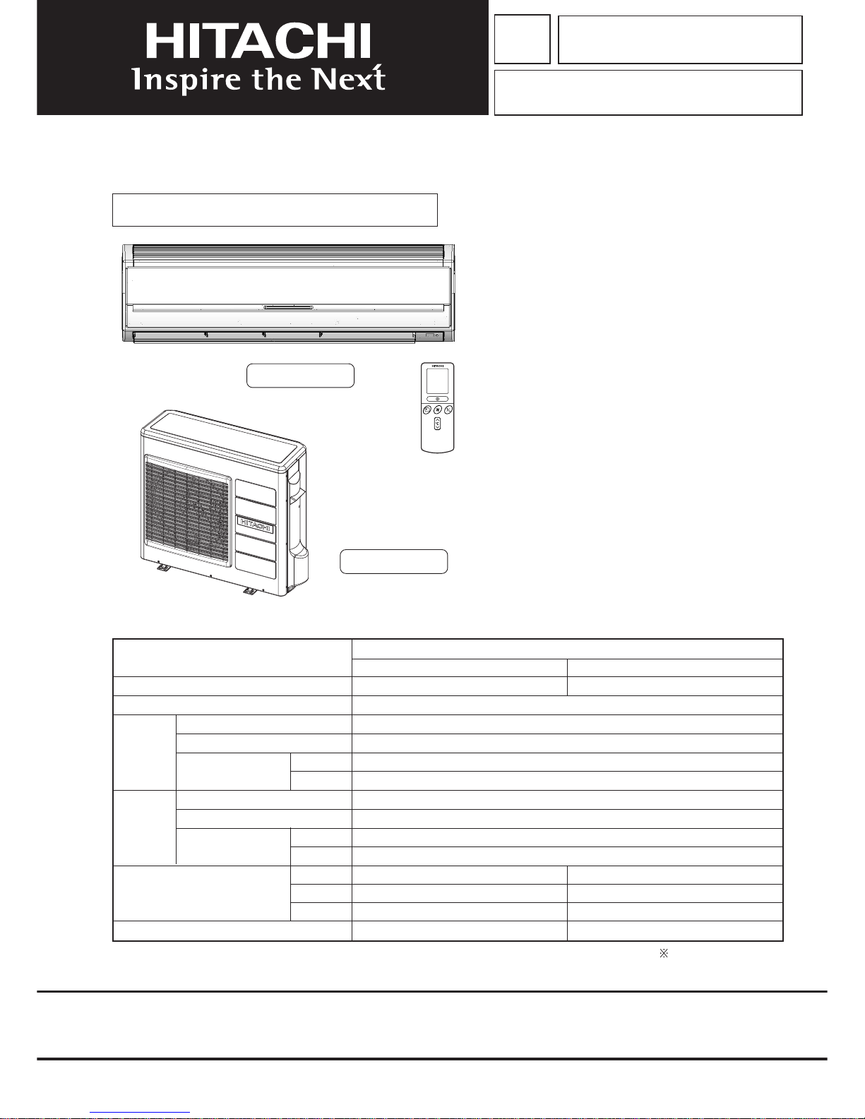
ROOM AIR CONDITIONER
INDOOR UNIT + OUTDOOR UNIT
JANUARY 2010
Refrigeration & Air-Conditioning Division
SERVICE MANUAL
PM
REFER TO THE FOUNDATION MANUAL
TECHNICAL INFORMATION
FOR SERVICE PERSONNEL ONLY
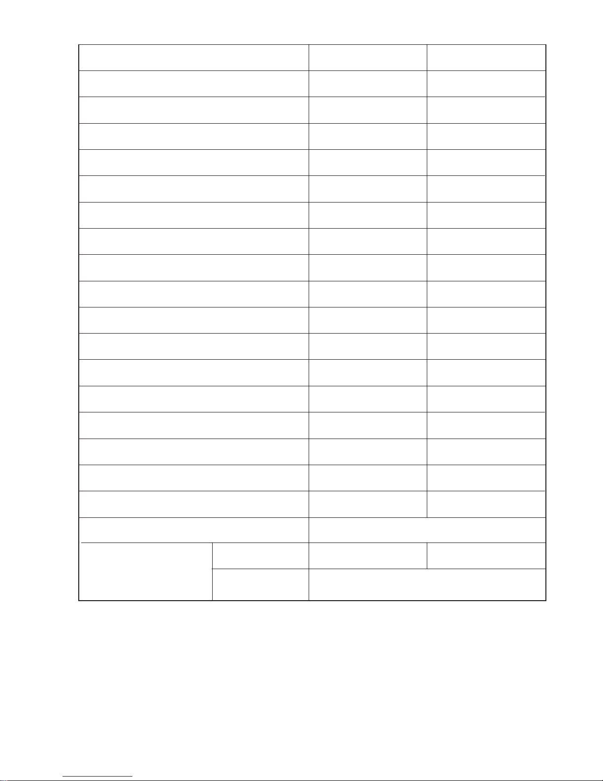
SPECIFICATIONS
RAS-70YH7
CONTENTS
CAUTION ----------------------------------------------------------------- 4
SPECIFICATIONS ----------------------------------------------------- 5
INSTALLATION --------------------------------------------------------- 6
HOW TO USE ---------------------------------------------------------- 7
CONSTRUCTION AND DIMENSIONAL DIAGRAM ------- 29
MAIN PARTS COMPONENT ------------------------------------- 31
WIRING DIAGRAM -------------------------------------------------- 33
CIRCUIT DIAGRAM ------------------------------------------------- 35
PRINTED WIRING BOARD LOCATION DIAGRAM ------- 41
BLOCK DIAGRAM --------------------------------------------------- 44
BASIC MODE --------------------------------------------------------- 45
REFRIGERATING CYCLE DIAGRAM ------------------------- 59
DESCRIPTION OF MAIN CIRCUIT OPERATION --------- 61
SERVICE CALL Q & A -------------------------------------------- 74
TROUBLE SHOOTING --------------------------------------------- 78
PARTS LIST AND DIAGRAM ------------------------------------ 98
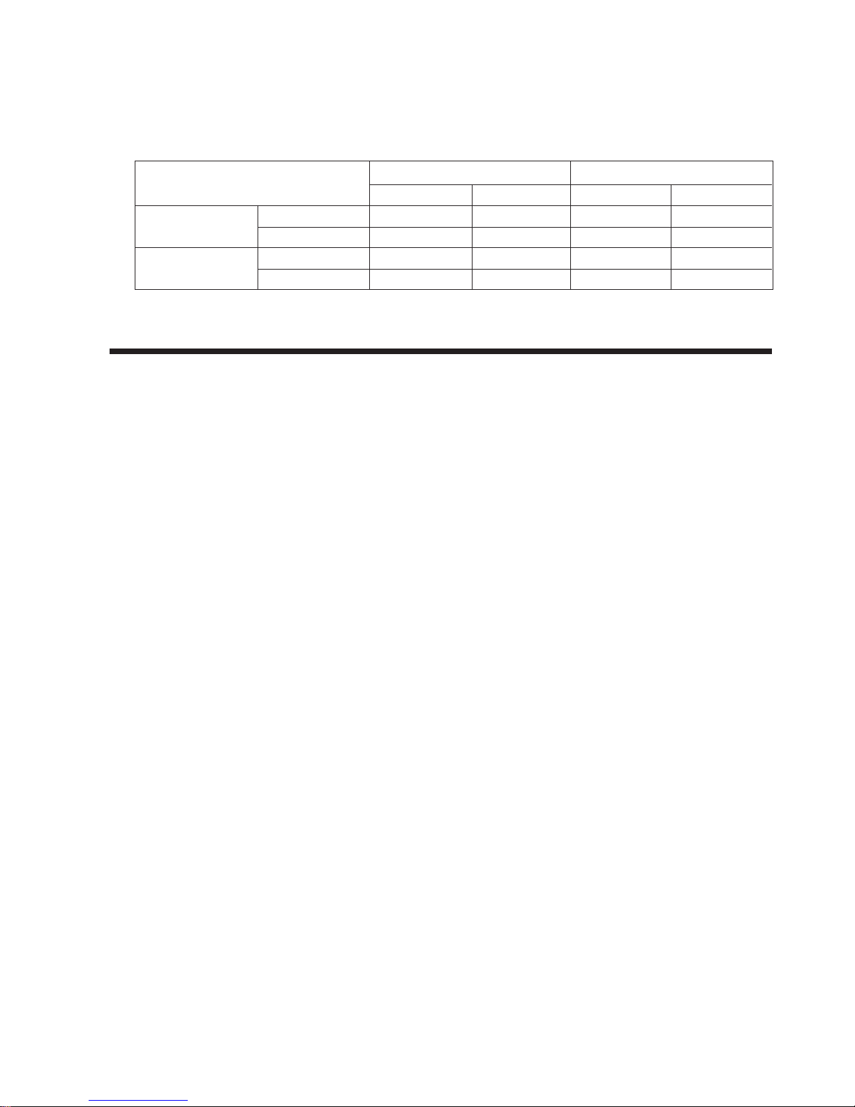
RAS-70YH7/RAC-70YH7
After installation
RAC-70YH7
(W)
(A)
(kW)
(B.T.U./h)
(W)
(A)
(kW)
(B.T.U./h)
W
H
D
(kg)
(WALL TYPE)
TYPE
MODEL
POWER SOURCE
TOTAL INPUT
TOTAL AMPERES
CAPACITY
TOTAL INPUT
TOTAL AMPERES
CAPACITY
DIMENSIONS
(mm)
NET WEIGHT
COOLING
HEATING
OUTDOOR UNIT
RAC-70YH7
INDOOR UNIT
RAS-70YH7
1150
333
245
15
1 Ø, 50/60 Hz, 220-240V
2,170 (200 – 2,820)
9.95
7.00 (1.50 – 8.00)
23,900 (5,120 – 27,315)
2,200 (200 – 2,970)
10.10
8.00 (1.50 – 9.20)
27,300 (5.119 – 31,396)
850
800
298
55
HITACHI
Page 2
– 1 –
SAFETY DURING REPAIR WORK
1. In order to disassemble and repair
the unit in question, be sure to
disconnect the power cord plug
from the power outlet before starting
the work.
2. If it is necessary to replace any parts, they should be replaced with respective genuine parts for the unit, and
the replacement must be effected in correct manner according to the instructions in the Service Manual of
the unit.
If the contacts of electrical parts
are defective, replace the
electrical parts without trying to
repair them.
3. After completion of repairs, the initial state
should be restored.
4. Lead wires should be connected and laid as
in the initial state.
5. Modification of the unit by user himself should
absolutely be prohibited.
6. Tools and measuring instruments for use in repairs or inspection should be accurately calibrated in advance.
7. In installing the unit having been repaired, be careful to prevent the occurence of any accident such as
electrical shock, leak of current, or bodily injury due to the drop of any part.
8. To check the insulation of the unit, measure the insulation resistance between the power cord plug and
grounding terminal of the unit. The insulation resistance should be 1M or more as measured by a 500V
DC megger.
9. The initial location of installation such as window, floor or the other should be checked for being and safe
enough to support the repaired unit again.
If it is found not so strong and safe, the unit should be installed at the initial location reinforced or at a new
location.
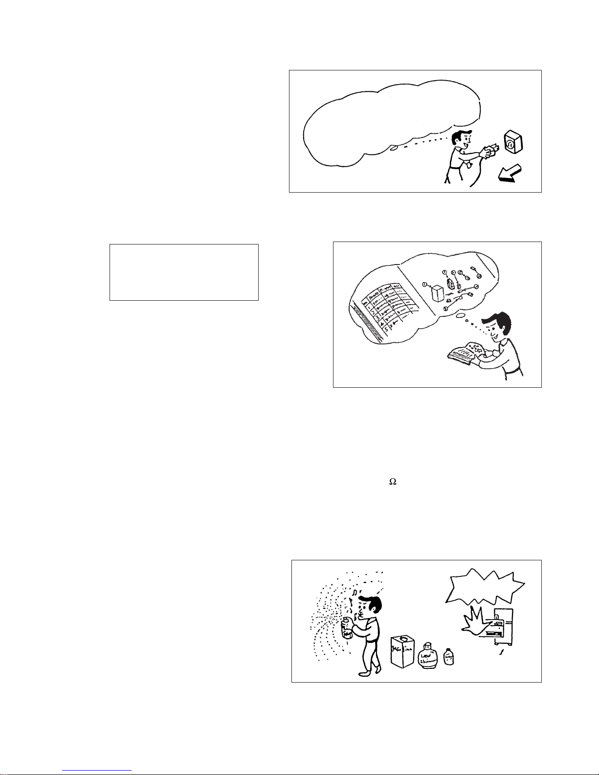
10. Any inflammable thing should never
be placed about the location of
installation.
11. Check the grounding to see whether
it is proper or not, and if it is found
improper, connect the grounding
terminal to the earth.
First, I must disconnect
the power cord plug
from the power outlet.
DANGER
Page 3
– 2 –
WORKING STANDARDS FOR PREVENTING BREAKAGE OF SEMICONDUCTORS
1. Scope
The standards provide for items to be generally observed in carrying and handling semiconductors in relative
manufacturers during maintenance and handling thereof. (They apply the same to handling of abnormal goods
such as rejected goods being returned).
2. Object parts
(1) Micro computer
(2) Integrated circuits (IC)
(3) Field-effect transistors (FET)
(4) P.C. boards or the like on which the parts mentioned in (1) and (2) of this paragraph are equipped.
3. Items to be observed in handling
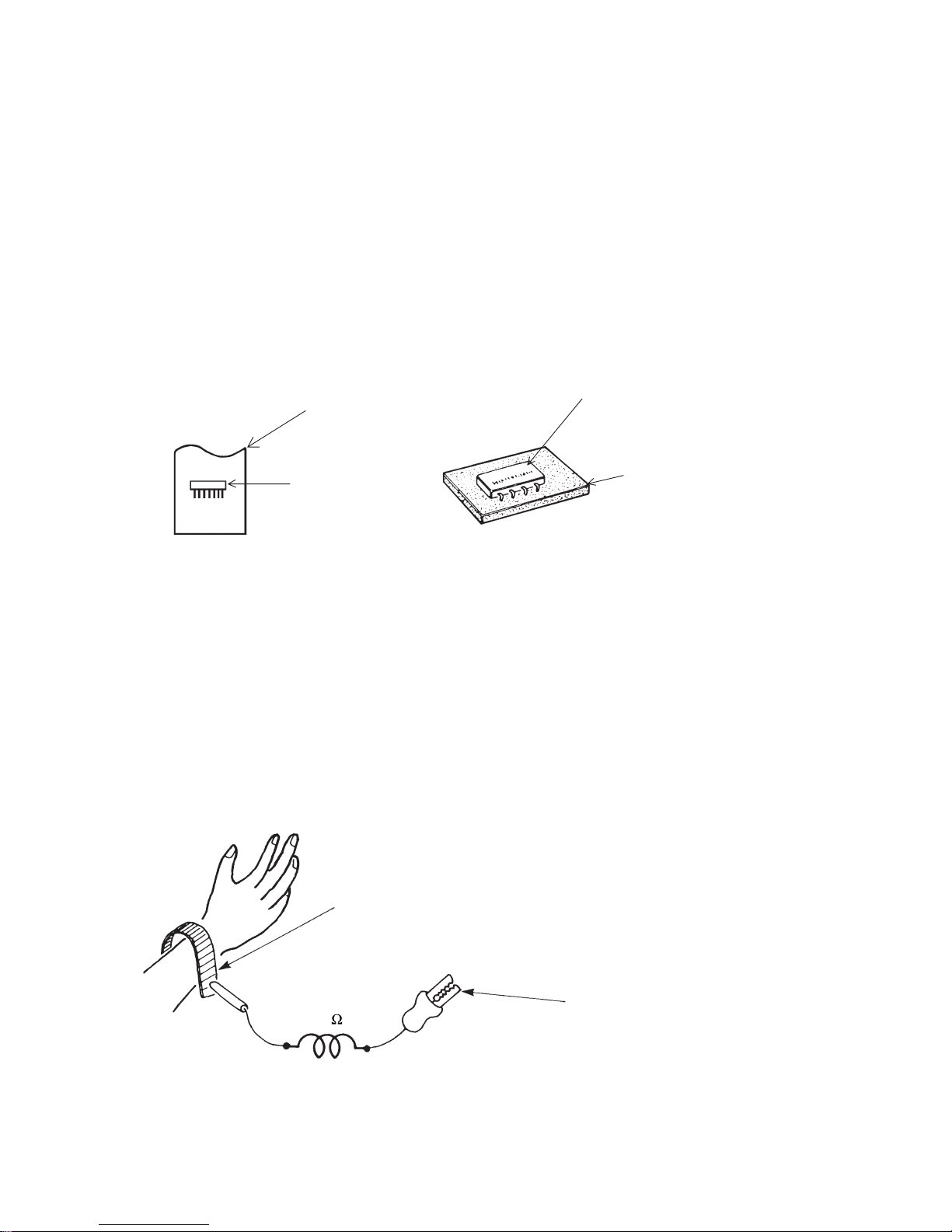
(1) Use a conductive container for carrying and storing of parts. (Even rejected goods should be handled in
the same way).
Fig. 1. Conductive Container
(2) When any part is handled uncovered (in counting, packing and the like), the handling person must always
use himself as a body earth. (Make yourself a body earth by passing one M ohm earth resistance through
a ring or bracelet).
(3) Be careful not to touch the parts with your clothing when you hold a part even if a body earth is being
taken.
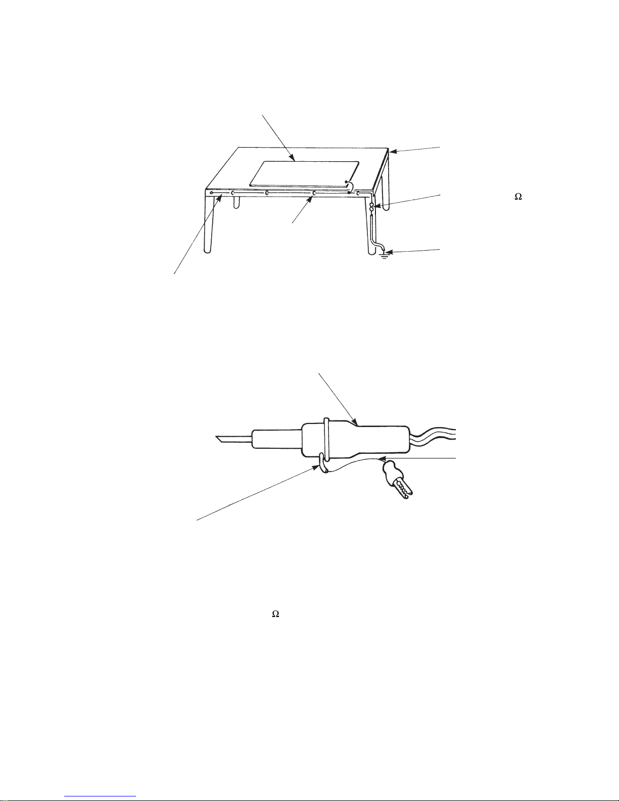
(4) Be sure to place a part on a metal plate with grounding.
(5) Be careful not to fail to turn off power when you repair the printed circuit board. At the same time, try
to repair the printed circuit board on a grounded metal plate.
1M
Fig. 2. Body Earth
Body earth
(Elimik conductive band)
Clip for connection with a
grounding wire
IC
A conductive polyvinyl bag
IC
Conductive sponge
Page 4
– 3 –
(6) Use a three wire type soldering iron including a grounding wire.
Bare copper wire (for body earth)
Working
table
Resistor of 1 M (1/2W)
Earth wire
Fig. 3. Grounding of the working table
Screw stop at the screwed
part using a rag plate
Soldering iron
Grounding
wire
Fig. 4. Grounding a soldering iron
Use a high insulation mode (100V, 10M or higher) when ordinary iron is to be used.
(7) In checking circuits for maintenance, inspection or some others, be careful not to have the test probes of the
measuring instrument shortcircuit a load circuit or the like.
Metal plate (of aluminium, stainless steel, etc.)
Staple
Page 5

– 4 –
1. In quiet or stop operation, slight flowing noise of refrigerant in the refrigerating cycle is heard occasionally,
but this noise is not abnormal for the operation.
2. When it thunders near by, it is recommended to stop the operation and to disconnect the power cord plug
from the power outlet for safety.
3. In the event of power failure, the airconditioner will restart automatically in the previously selected mode
once the power is restored. In the event of power failure during TIMER operation, the timer will be reset
and the unit will begin or stop operating under a new timer setting.
4. If the room air conditioner is stopped by adjusting thermostat, or missoperation, and re-start in a moment,
there is occasion that the cooling and heating operation does not start for 3 minutes, it is not abnormal
and this is the result of the operation of IC delay circuit. This IC delay circuit ensures that there is no
danger of blowing fuse or damaging parts even if operation is restarted accidentally.
5. This room air conditioner should not be used at the cooling operation when the outside temperature is
below –10°C (14°F).
6. This room air conditioner (the reverse cycle) should not be used when the outside temperature is below
–15°C (5°F).
If the reverse cycle is used under this condition, the outside heat exchanger is frosted and efficiency falls.
7. When the outside heat exchanger is frosted, the frost is melted by operating the hot gas system, it is not
trouble that at this time fan stops and the vapour may rise from the outside heat exchanger.
CAUTION
Page 6
– 5 –
SPECIFICATIONS
MODEL
FAN MOTOR
FAN MOTOR CAPACITOR
FAN MOTOR PROTECTOR
COMPRESSOR
COMPRESSOR MOTOR CAPACITOR
OVERLOAD PROTECTOR
OVERHEAT PROTECTOR
FUSE (MICRO COMPUTER CIRCUIT)
POWER RELAY
POWER SWITCH
TEMPORARY SWITCH
TEST/SERVICE SWITCH
TRANSFORMER
VARISTOR
NOISE SUPPRESSOR
THERMOSTAT
REMOTE CONTROL SWITCH (LIQUID CRYSTAL)
FUSE CAPACITY
RAS-70YH7
30 W
NO
NO
–
NO
NO
NO
3.15A
G4A
NO
YES
NO
NO
416NR
NO
YES(IC)
YES
NO
NO
JU1015D9
NO
NO
YES
NO
G4A
NO
NO
YES
NO
450NR
NO
YES(IC)
NO
30 A TIME DELAY FUSE
---------- ❈ 1850gUNIT
REFRIGERANT CHARGING
VOLUME
(Refrigerant R410A)
CHARGELESS
PIPES (MAX. 30m)
PIPES (MIN. 3m)
RAC-70YH7
47 W
Page 7
– 6 –
a
b
o
u
t
0
.
5
m
2
1
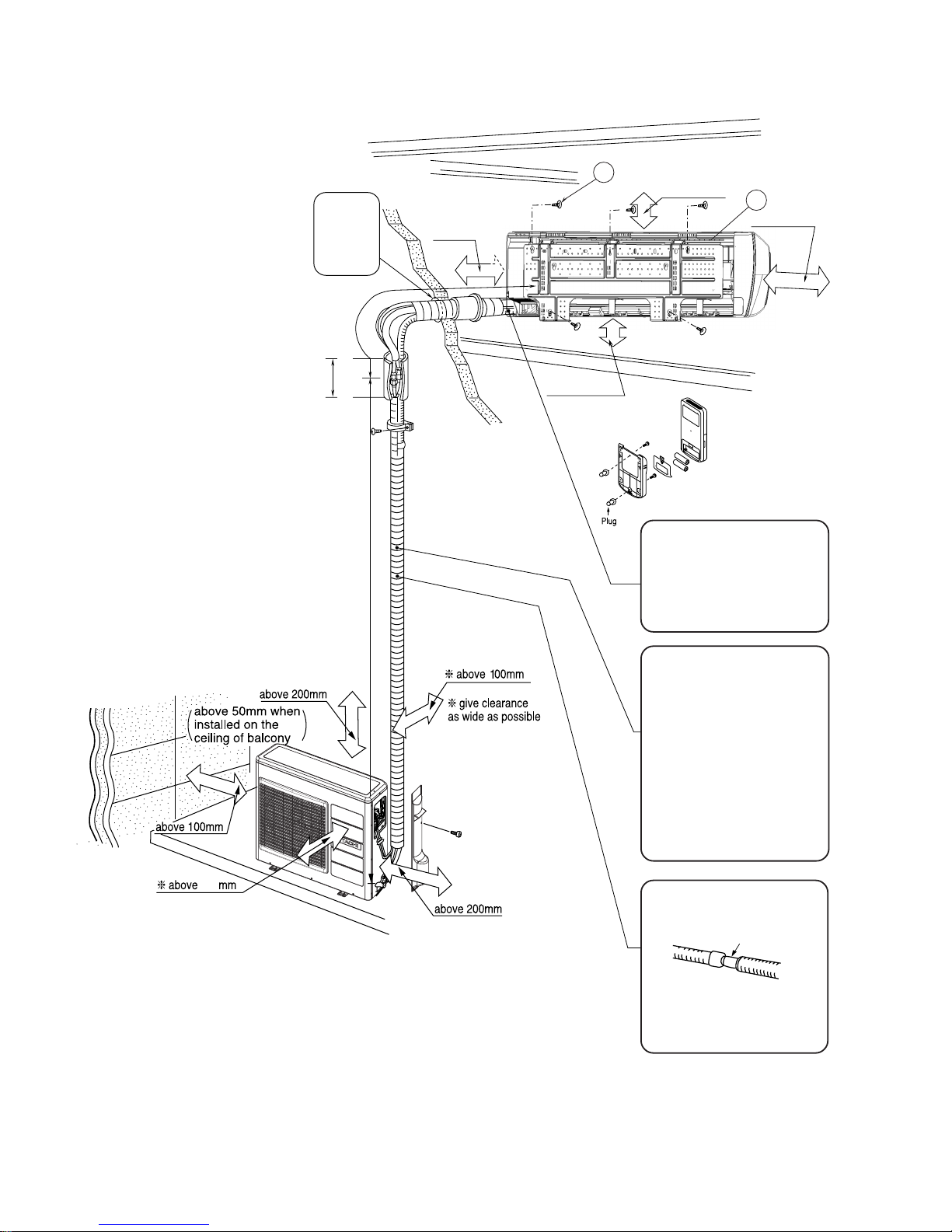
above 300 mm
Maximum pipe length 30m
Minimum pipe length 3m
must not bend
above 2300 mm
above
200 mm
above 50mm
above 100mm
Be sure to
completely
seal any
gap with
putty.
700
Figure showing the installation of Indoor and Outdoor unit
● The difference in height
between the indoor and
outdoor unit should be kept
max 20m.
● The connecting pipe, no
matter big or small, should
all be insulated with
insulation pipe and then
wrapped with vinyl tape.
(The insulator will
deteriorate if it is not
wrapped with tape).
The connection of insulated
drain hose.
Please use insulated drain
hose for the indoor piping
(commercial product).
The indoor piping should be
insulated with the enclosed
insulation pipe. (If the
insulator is insufficient,
please use commersial
products).
inner diameter ø 16mm
Page 8
– 7 –
РУССКИЙ
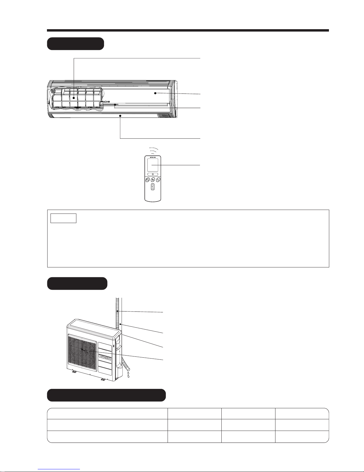
INDOOR UNIT
NAMES AND FUNCTIONS OF EACH PART
AIR FILTER
To prevent dust from coming into the indoor
unit.
(Refer Instruction manual)
FRONT PANEL (AIR INLET).
INDOOR UNIT INDICATORS
Light indicator showing the operating condition.
(Refer page 8)
HORIZONTAL DEFLECTOR
●
VERTICAL
DEFLECTOR (AIR OUTLET)
(Refer Instruction manual)
REMOTE CONTROLLER
Send out operation signal to the indoor unit. So
as to operate the whole unit.
(Refer Instruction manual)
●
WIDTH (mm)
1150
850
MODEL
RAS-70YH7
RAC-70YH7
HEIGHT (mm)
333
800
DEPTH (mm)
245
298
MODEL NAME AND DIMENSIONS
OUTDOOR UNIT
DRAIN PIPE
Condensed water drain to outside.
CONNECTING CORD
AIR INLET (BACK, LEFT SIDE)
AIR OUTLET
● Air cleansing filters are not washable and can be use in 1 year time. Type number for this air
cleansing filter is <SPX-CFH12>. Please use this number for ordering when you want to renew it.
● Air cleansing filter should be cleaned every month or sooner if noticeable loading occurs. When
used overtime, it may loose its deodorizing function. For maximum performance, it is recommended
to replace it every 1 year depending on application requirements.
NOTE
Page 9
– 8 –
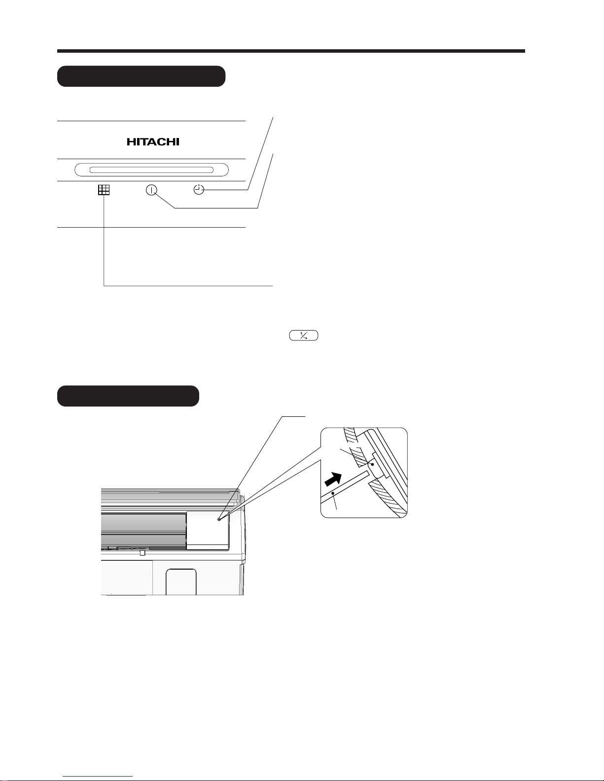
Press
Temporary Switch
emporary Switch
Non-conductor Stick
Non-conductor Stick
INDOOR UNIT INDICATORS
TEMPORARY SWITCH
OPERATION INDICATOR
TIMER LAMP
This lamp lights when the timer is working.
OPERATION LAMP
This lamp lights during operation.
The OPERATION LAMP flashes in the following cases
during heating.
(1) During preheating
For about 2–3 minutes after starting up.
(2) During defrosting
Defrosting will be performed about once an hour
when frost forms on the heat exchanger of the
outdoor unit, for 5–10 minutes each time.
FILTER LAMP
When the device is operated for a total of about 200
hours, the FILTER lamp lights to indicate that it is time
to clean the filter. The lamp goes out when the
“ (AUTO SWING)” button is pressed while the
device is on “STANDBY MODE”.
TEMPORARY SWITCH
Use this switch to start and stop when the remote controller does not work. [Use non-conductor stick
(example: toothpick)]
● By pressing the temporary switch, the operation is done in previously set operation mode.
● When the operation is done using the temporary switch after the power source is turned off and turn on
again, the operation is done in automatic mode.
Page 10
– 9 –
РУССКИЙ
MEMO
.....................................................................................................................................................................................
.....................................................................................................................................................................................
.....................................................................................................................................................................................
.....................................................................................................................................................................................
.....................................................................................................................................................................................
.....................................................................................................................................................................................
.....................................................................................................................................................................................
.....................................................................................................................................................................................
.....................................................................................................................................................................................
.....................................................................................................................................................................................
.....................................................................................................................................................................................
.....................................................................................................................................................................................
.....................................................................................................................................................................................
.....................................................................................................................................................................................
.....................................................................................................................................................................................
.....................................................................................................................................................................................
.....................................................................................................................................................................................
.....................................................................................................................................................................................
.....................................................................................................................................................................................
.....................................................................................................................................................................................
.....................................................................................................................................................................................
.....................................................................................................................................................................................
.....................................................................................................................................................................................
.....................................................................................................................................................................................
.....................................................................................................................................................................................
.....................................................................................................................................................................................
.....................................................................................................................................................................................
Minimum Maximum Minimum Maximum
Indoor
Dry bulb °C2132 2027
Wet bulb °C1523 1219
Outdoor
Dry bulb °C21 43 2 21
Wet bulb °C15 26 1 15
Note
● Avoid to use the room air conditioner for cooling operation when the outside temperature is below
–10°C (14°F).
The recommended maximum and minimum operating temperatures of the hot and cold sides
should be as below:
Cooling Heating
Page 11
– 10 –
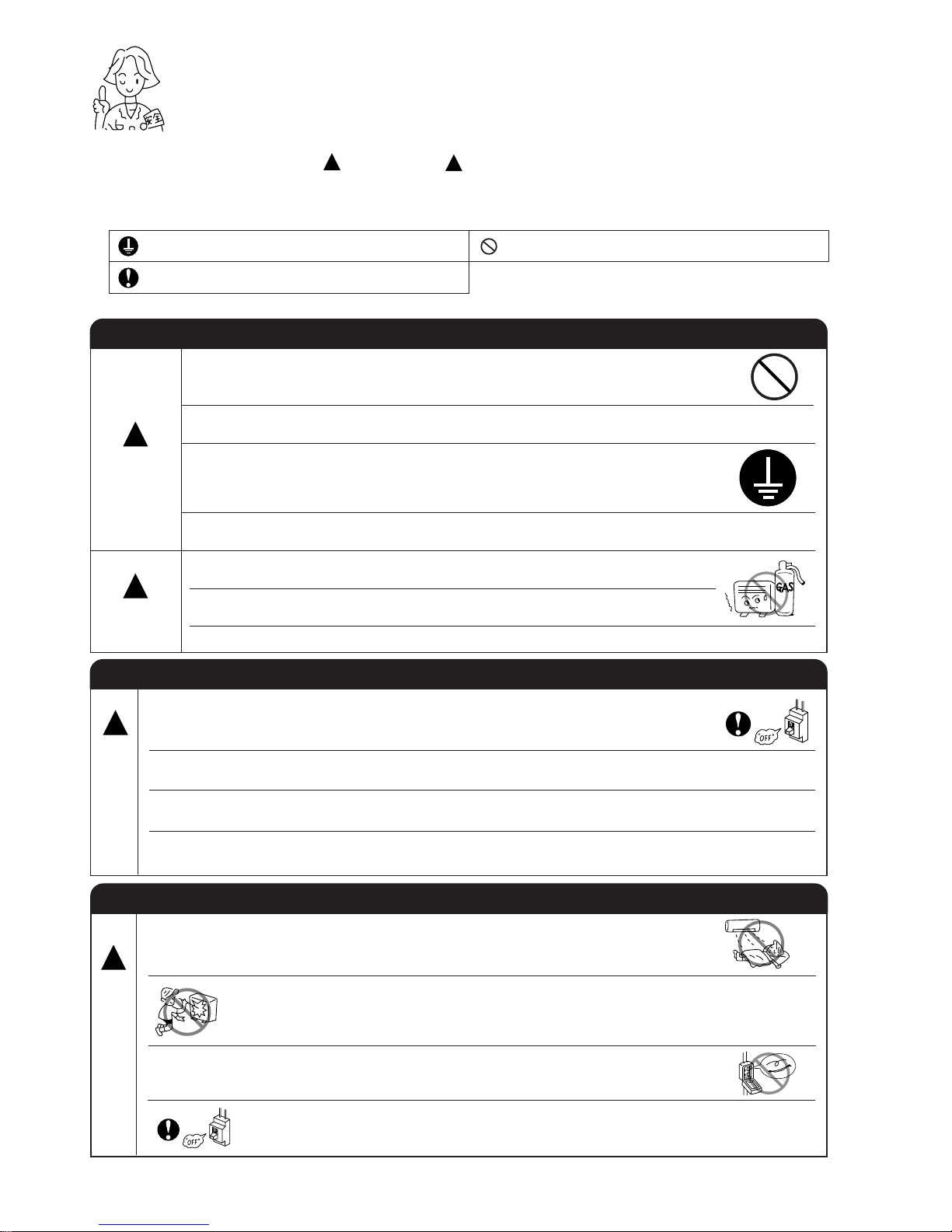
!
SAFETY PRECAUTION
●
Please read the “Safety Precaution” carefully before operating the unit to ensure correct usage of the unit.
●
Pay special attention to signs of “ Warning” and “ Caution”. The “Warning” section contains matters which,
if not observed strictly, may cause death or serious injury. The “Caution” section contains matters which may
result in serious consequences if not observed properly. Please observe all instructions strictly to ensure safety.
●
The sign indicate the following meanings.
●
Please keep this manual after reading.
WARNING
PRECAUTIONS DURING INSTALLATION
●
Do not reconstruct the unit.
Water leakage, fault, short circuit or fire may occur if you reconstruct the unit by
yourself.
●
Please ask your sales agent or qualified technician for the installation of your unit.
Water leakage, short circuit or fire may occur if you install the unit by yourself.
●
Please use earth line.
Do not place the earth line near water or gas pipes, lightning-conductor, or the
earth line of telephone. Improper installation of earth line may cause electric
shock.
●
Be sure to use the specified piping set for R410A. Otherwise, this may result in
broken copper pipes or faults.
●
A circuit breaker should be installed depending on the mounting site of the unit.
Without a circuit breaker, the danger of electric shock exists.
●
Do not install near location where there is flammable gas. The outdoor unit may
catch fire if flammable gas leaks around it.
●
Please ensure smooth flow of water when installing the drain hose.
CAUTION
!
!
PRECAUTIONS DURING OPERATION
●
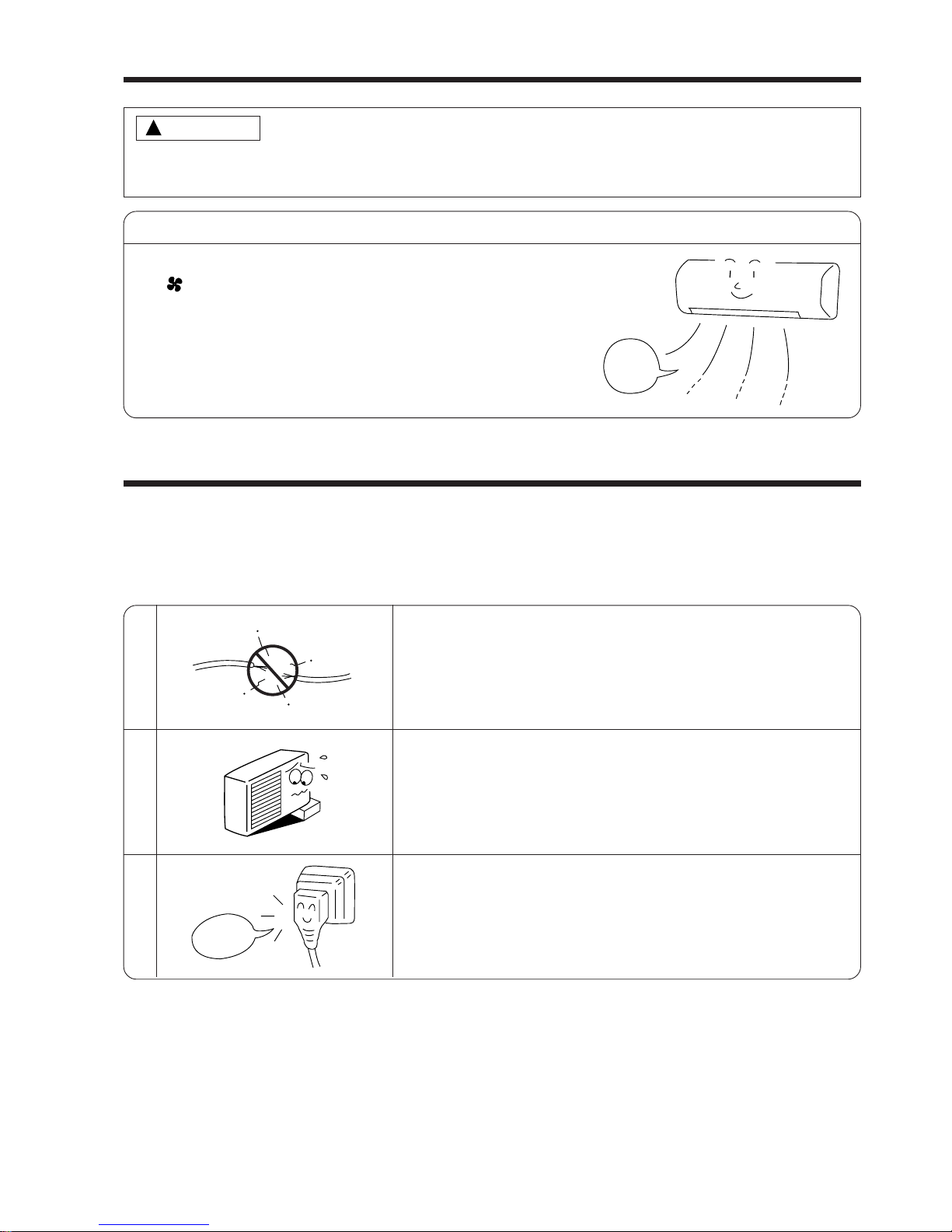
Avoid an extended period of direct air flow for your health.
W
A
R
N
I
N
G
!
●
Do not insert a finger, a rod or other objects into the air outlet or inlet. As the fan
is rotating at a high speed, it will cause injury. Before cleaning, be sure to stop the
operation and turn the breaker OFF.
●
During thunder storm, disconnect and turn off the circuit breaker.
●
Do not use any conductor as fuse wire, this could cause fatal accident.
!
Make sure to connect earth line.
Indicates the instructions that must be followed.
The sign in the figure indicates prohibition.
PRECAUTIONS DURING SHIFTING OR MAINTENANCE
●
Should abnormal situation arises (like burning smell), please stop operating the unit
and turn off the circuit breaker. Contact your agent. Fault, short circuit or fire may
occur if you continue to operate the unit under abnormal situation.
●
Please contact your agent for maintenance. Improper self maintenance may cause
electric shock and fire.
●
Please contact your agent if you need to remove and reinstall the unit. Electric
shock or fire may occur if you remove and reinstall the unit yourself improperly.
●
If the supply cord is damaged, it must be replaced by the special cord obtainable
at authorized service/parts centers.
W
A
R
N
I
N
G
!
Page 12
– 11 –
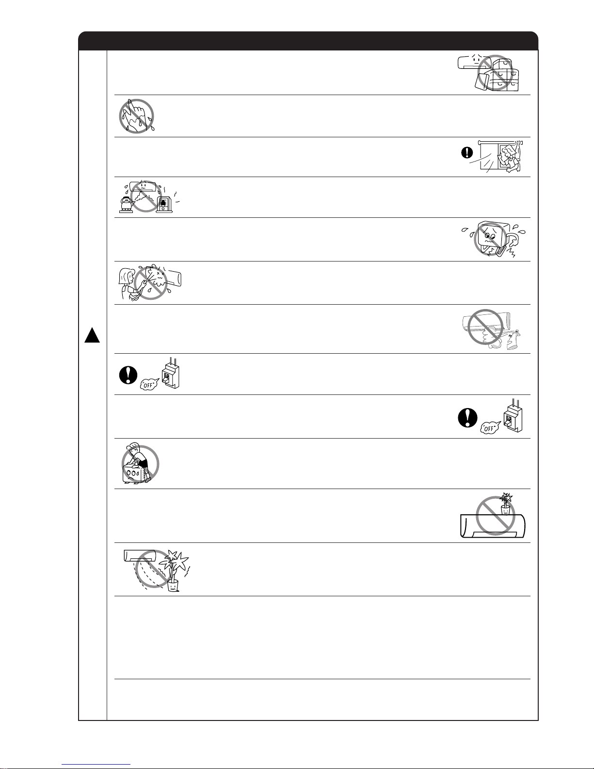
PRECAUTIONS DURING OPERATION
●
Do not attempt to operate the unit with wet hands, this could cause fatal
accident.
●
When operating the unit with burning equipments, regularly ventilate the
room to avoid oxygen insufficiency.
●
Do not direct the cool air coming out from the air-conditioner panel to face
household heating apparatus as this may affect the working of apparatus
such as the electric kettle, oven etc.
●
Do not use any aerosol or hair sprays near the indoor unit. This chemical
can adhere on heat exchanger fin and blocked the evaporation water flow
to drain pan. The water will drop on tangential fan and cause water splashing
out from indoor unit.
●
Please ensure that outdoor mounting frame is always stable, firm and
without defect. If not, the outdoor unit may collapse and cause danger.
●
Do not splash or direct water to the body of the unit when cleaning it as this
may cause short circuit.
●
When operating the unit with the door and windows opened, (the room humidity is always above
80%) and with the air deflector facing down or moving automatically for a long period of time,
water will condense on the air deflector and drips down occasionally. This will wet your furniture.
Therefore, do not operate under such condition for a long time.
●
If the amount of heat in the room is above the cooling or heating capability of the unit (for
example: more people entering the room, using heating equipments and etc.), the preset room
temperature cannot be achieved.
●
This appliance is not intended for use by young children or infirm persons unless they have been
adequately supervised by a responsible person to ensure that they can use the appliance safely.
●
Young children should be supervised to ensure that they do not play with the appliance.
●
Do not climb on the outdoor unit or put objects on it.
●
Please switch off the unit and turn off the circuit breaker during cleaning, the
high-speed fan inside the unit may cause danger.
●
Turn off the circuit breaker if the unit is not to be operated for a long period.
C
A
U
T
I
O
N
!
●
The product shall be operated under the manufacturer specification and
not for any other intended use.
●
Do not put water container (like vase) on the indoor unit to avoid water
dripping into the unit. Dripping water will damage the insulator inside the unit
and causes short-circuit.
●
Do not place plants directly under the air flow as it is bad for the plants.
Page 13
– 12 –
SILENT
LOW
MED
HI
AUTO
HEAT
DEHUMIDIFY
COOL
FAN
FAN SPEED
SLEEPING
STOP (CANCEL)
START (RESERVE)
START/STOP
TIME
TIMER SET
TIMER SELECT
PARALLEL SWING
SYMMETRY SWING
OR
ON TIMER
OFF TIMER
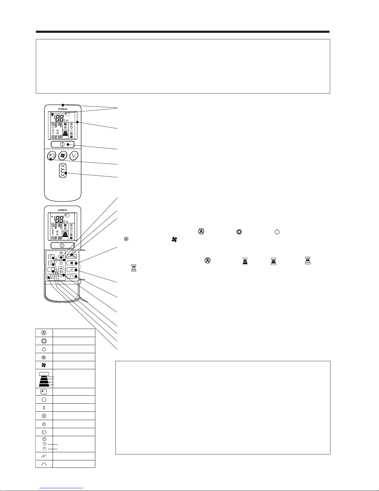
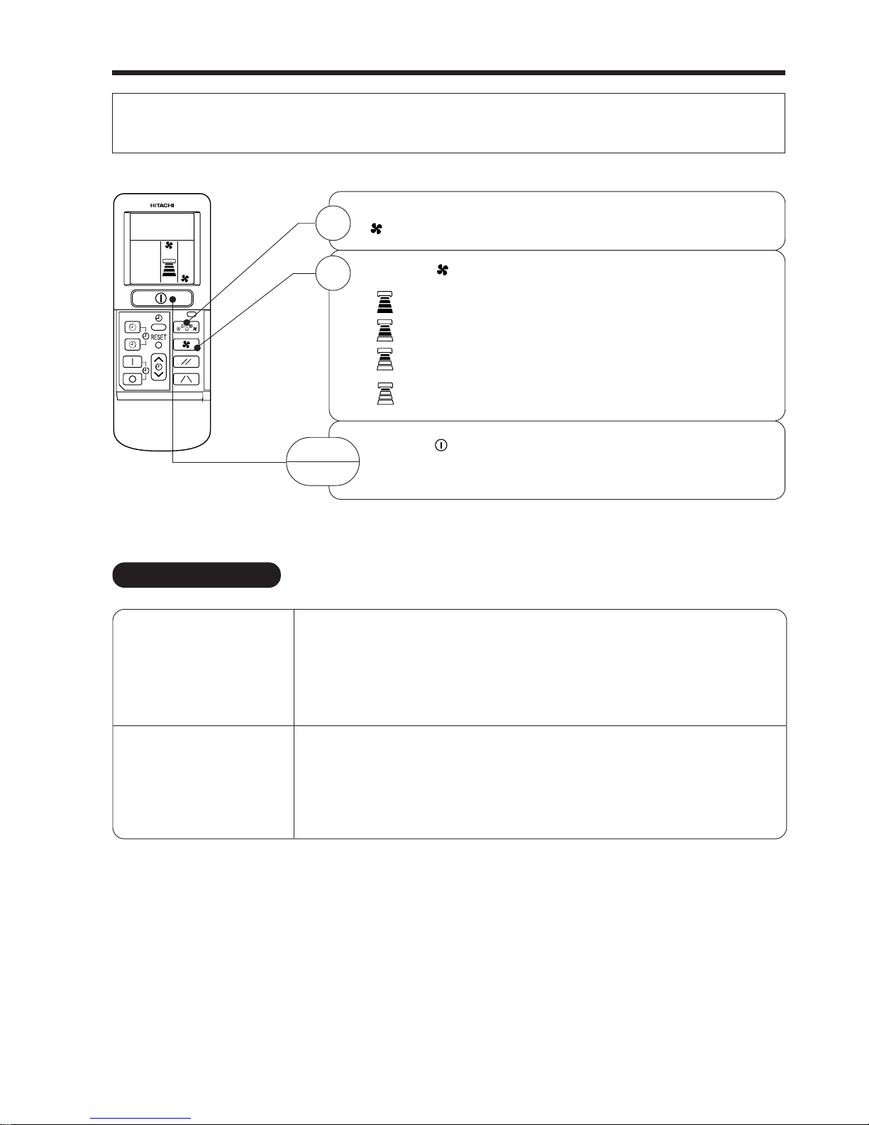
NAMES AND FUNCTIONS OF REMOTE CONTROL UNIT
REMOTE CONTROLLER
● This controls the operation of the indoor unit. The range of control is about 7 meters. If indoor lighting is controlled
electronically, the range of control may be shorter.
This unit can be fixed on a wall using the fixture provided. Before fixing it, make sure the indoor unit can be controlled
from the remote controller.
● Handle the remote controller with care. Dropping it or getting it wet may compromise its signal transmission capability.
● After new batteries are inserted into the remote controller, the unit will initially require approximately 10 seconds to
respond to commands and operate.
●
Signal emitting window/transmission sign
Point this window toward the indoor unit when controlling it.
The transmission sign blinks when a signal is sent.
● Display
This indicates the room temperature selected, current time, timer status, function
and intensity of circulation selected.
● START/STOP button
Press this button to start operation. Press it again to stop operation.
● SLEEP button
Use this button to set the sleep timer.
● TEMPERATURE buttons
Use these buttons to raise or lower the temperature setting. (Keep pressed, and
the value will change more quickly.)
● TIME button
Use this button to set and check the time and date.
● RESET buttons
● FUNCTION selector
Use this button to select the operating mode. Every time you press it,
the mode will change from (AUTO) to (HEAT) to (DEHUMIDIFY) to
(COOL) and to (FAN) cyclically.
● FAN SPEED selector
This determines the fan speed. Every time you press this button, the intensity
of circulation will change from (AUTO) to (HI) to (MED) to (LOW)
to (SILENT) (This button allows selecting the optimal or preferred fan speed
for each operation mode).
● PARALLEL SWING button
Controls the angle of the vertical air deflectors to parallel.
● SYMMETRY SWING button
Controls the angle of the vertical air deflectors to symmetry.
● TIMER control
Use this button to set the timer.
● OFF-TIMER button Select the turn OFF time.
● ON-TIMER button Select the turn ON time.
● RESERVE button Time setting reservation.
● CANCEL button Cancel time reservation.
Precautions for Use
● Do not put the remote controller in the following places.
● Under direct sunlight.
● In the vicinity of a heater.
● Handle the remote controller carefully. Do not drop it on the floor, and
protect it from water.
● Once the outdoor unit stops, it will not restart for about 3 minutes (unless
you turn the power switch off and on or unplug the power cord and plug
it in again).
This is to protect the device and does not indicate a failure.
● If you press the FUNCTION selector button during operation, the device
may stop for about 3 minutes for protection.
Page 14
– 13 –
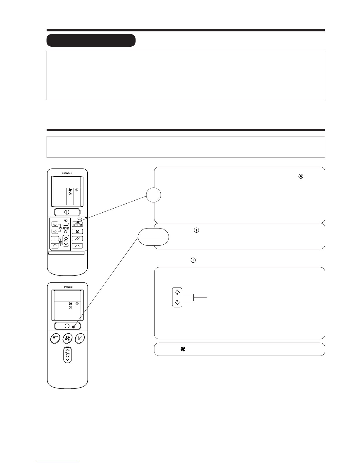
AUTOMATIC OPERATION
The device will automatically determine the mode of operation, HEAT, COOL or DEHUMIDIFY depending on the current room
temperature. The selected mode of operation will change when the room temperature varies. However the mode of operation will
not change when indoor unit connected to multi type outdoor unit.
VARIOUS FUNCTIONS
■ Auto Restart Control
● If there is a power failure, operation will be automatically restarted when the power is resumed with previous operation mode
and airflow direction.
(As the operation is not stopped by remote controller.)
● If you intend not to continue the operation when the power is resumed, switch off the power supply.
When you switch on the circuit breaker, the operation will be automatically restarted with previous operation mode and airflow
direction.
Note: 1. If you do not require Auto Restart Control, please consult your sales agent or OFF by remote control.
2. Auto Restart Control is not available when Timer or Sleep Timer mode is set.
■ As the settings are stored in memory in the remote controller, you only have
to press the (START/STOP) button next time.
Press the FUNCTION selector so that the display indicates the (AUTO)
mode of operation.
● When AUTO has been selected, the device will automatically determine
the mode of operation, HEAT, COOL or DEHUMIDIFY depending on
the current room temperature. However the mode of operation will
not change when indoor unit connected to multi type outdoor unit.
● If the mode automatically selected by the unit is not satisfactory,
manually change the mode setting (heat, dehumidify, cool or fan).
Press the (START/STOP) button.
Operation starts with a beep.
Press the button again to stop operation.
You can raise or lower the temperature setting as necessary by maximum of
3°C.
Press the temperature button and the temperature
setting will change by 1°C each time.
● The preset temperature and the actual room temperature may vary
somewhat depending on conditions.
● The display does not indicate the preset temperature in the AUTO mode.
If you change the setting, the indoor unit will produce a beep.
1
START
STOP
°C
Press the (FAN SPEED) button, AUTO, LOW and SILENT is available.
Page 15
– 14 –
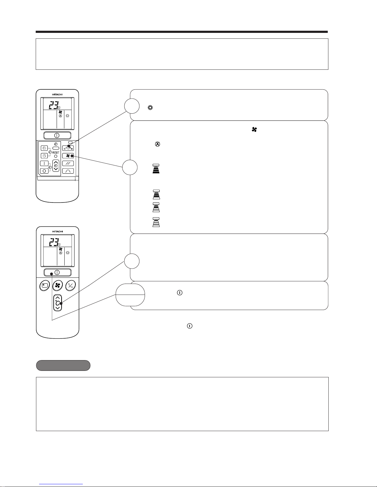
HEATING OPERATION
● Use the device for heating when the outdoor temperature is under 21°C.
When it is too warm (over 21°C), the heating function may not work in order to protect the device.
● In order to keep reliability of the device, please use this device above -15°C of the outdoor temperature.
Press the FUNCTION selector so that the display indicates
(HEAT).
Set the desired FAN SPEED with the (FAN SPEED) button
(the display indicates the setting).
(AUTO) : The fan speed changes automatically
according to the temperature of the air which
blows out.
(HI) : Economical as the room will become warm
quickly.
But you may feel a chill at the beginning.
(MED) : Fan speed slow.
(LOW) : Fan speed slower.
(SILENT) : Fan speed ultra slower.
Set the desired room temperature with the TEMPERATURE
buttons (the display indicates the setting).
The temperature setting and the actual room temperature may
vary somewhat depending on conditions.
Press the (START/STOP) button. Heating operation starts
with a beep. Press the button again to stop operation.
■ As the settings are stored in memory in the remote controller, you only
have to press the (START/STOP) button next time.
1
2
3
START
STOP
■ Defrosting
Defrosting will be performed about once an hour when frost forms on the heat exchange of the outdoor
unit, for 5~10 minutes each time.
During defrosting operation, the operation lamp blinks in cycle of 3 seconds on and 0.5 second off.
The maximum time for defrosting is 20 minutes.
However, if it is connected to multi type outdoor unit, the maximum time for defrosting is 15 minutes.
(If the piping length used is longer than usual, frost will likely to form.)
Page 16
– 15 –
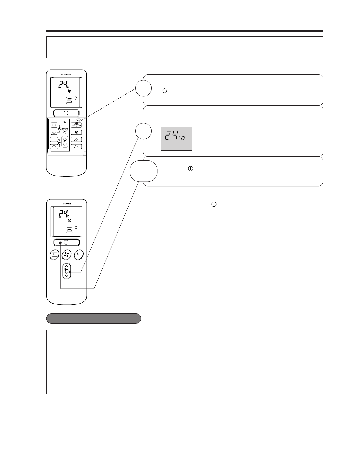
DEHUMIDIFYING OPERATION
Use the device for dehumidifying when the room temperature is over 16°C.
When it is under 15°C, the dehumidifying function will not work.
■ Dehumidifying Function
● When the room temperature is higher than the temperature setting: The device will dehumidify the
room, reducing the room temperature to the preset level.
When the room temperature is lower than the temperature setting: Dehumidifying will be performed
at the temperature setting slightly lower than the current room temperature, regardless of the temperature
setting. The function will stop (the indoor unit will stop emitting air) as soon as the room temperature
becomes lower than the setting temperature.
● The preset room temperature may not be reached depending on the number of people present in the
room or other room conditions.
Set the desired room temperature with the TEMPERATURE
button (the display indicates the setting).
The range of 20-26˚C is recommended as
the room temperature for dehumidifying.
Press the (START/STOP) button. Dehumidifying operation
starts with a beep. Press the button again to stop operation.
2
■ As the settings are stored in memory in the remote controller, you
only have to press the
(START/STOP) button next time.
START
STOP
Press the FUNCTION selector so that the display indicates
(DEHUMIDIFY).
The FAN SPEED is set at LOW or SILENT.
1
Page 17
– 16 –
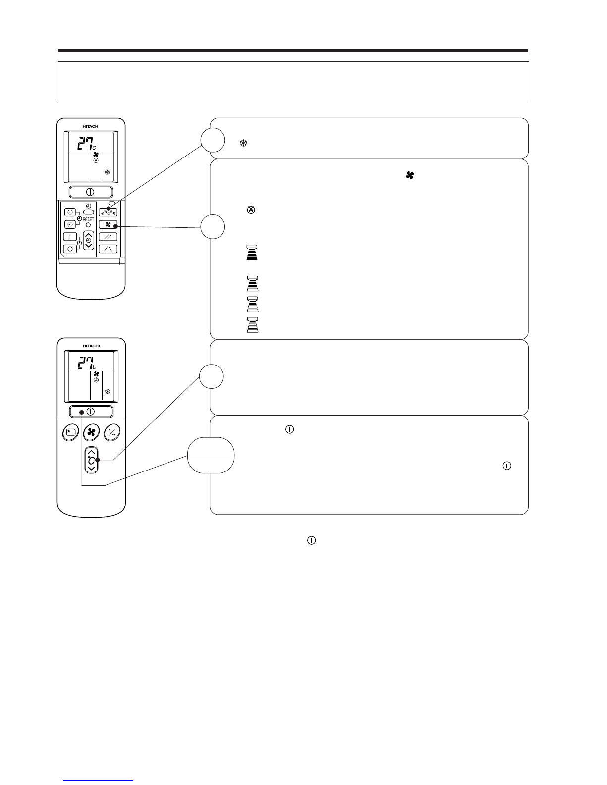
COOLING OPERATION
Use the device for cooling when the outdoor temperature is –10°C~ 43°C.
If in doors humidity is very high (80%), some dew may form on the air outlet grille of the indoor unit.
Press the FUNCTION selector so that the display indicates
(COOL).
Set the desired FAN SPEED with the
(FAN SPEED) button
(the display indicates the setting).
(AUTO) : The FAN SPEED is HI at first and varies
to MED or LOW automatically when the
preset temperature has been reached.
(HI) : Economical as the room will become cool
quickly.
(MED) : Fan speed slow.
(LOW) : Fan speed slower.
(SILENT) : Fan speed ultra slower.
Set the desired room temperature with the TEMPERATURE
button (the display indicates the setting).
The temperature setting and the actual room temperature may
vary some how depending on conditions.
Press the
(START/STOP) button. Cooling operation starts
with a beep. Press the button again to stop operation. The
cooling function does not start if the temperature setting is
higher than the current room temperature (even though the
(OPERATION) lamp lights). The cooling function will start as
soon as you set the temperature below the current room
temperature.
■ As the settings are stored in memory in the remote controller, you only
have to press the
(START/STOP) button next time.
1
2
START
STOP
3
Page 18
– 17 –
FAN SPEED (AUTO)
.....
When the AUTO fan speed mode is set in the cooling/heating operation:
For the heating operation
● When the difference of room temperature and setting temperature is
large, fan starts to run at HI speed.
● After room temperature reaches the preset temperature, the heating
operation, which changes the fan speed and room temperature to obtain
optimum conditions for natural healthful heating will be performed.
● When the difference of room temperature and setting temperature is
large, fan starts to run at HI speed.
● After room temperature reaches the preset temperature, the cooling
operation, which changes the fan speed and room temperature to obtain
optimum conditions for natural healthful cooling will be performed.
For the cooling operation
FAN OPERATION
You can use the device simply as an air circulator. Use this function to dry the interior of the indoor
unit at the end of summer.
Press the FUNCTION selector so that the display indicates
(FAN).
Press the (FAN SPEED) button.
(HI) : The strongest air blow.
(MED) : Fan speed slow.
(LOW) : Fan speed slower.
(SILENT) : Fan speed ultra slower.
Press the (START/STOP) button. Fan operation starts with
a beep. Press the button again to stop operation.
1
2
START
STOP
Page 19
– 18 –
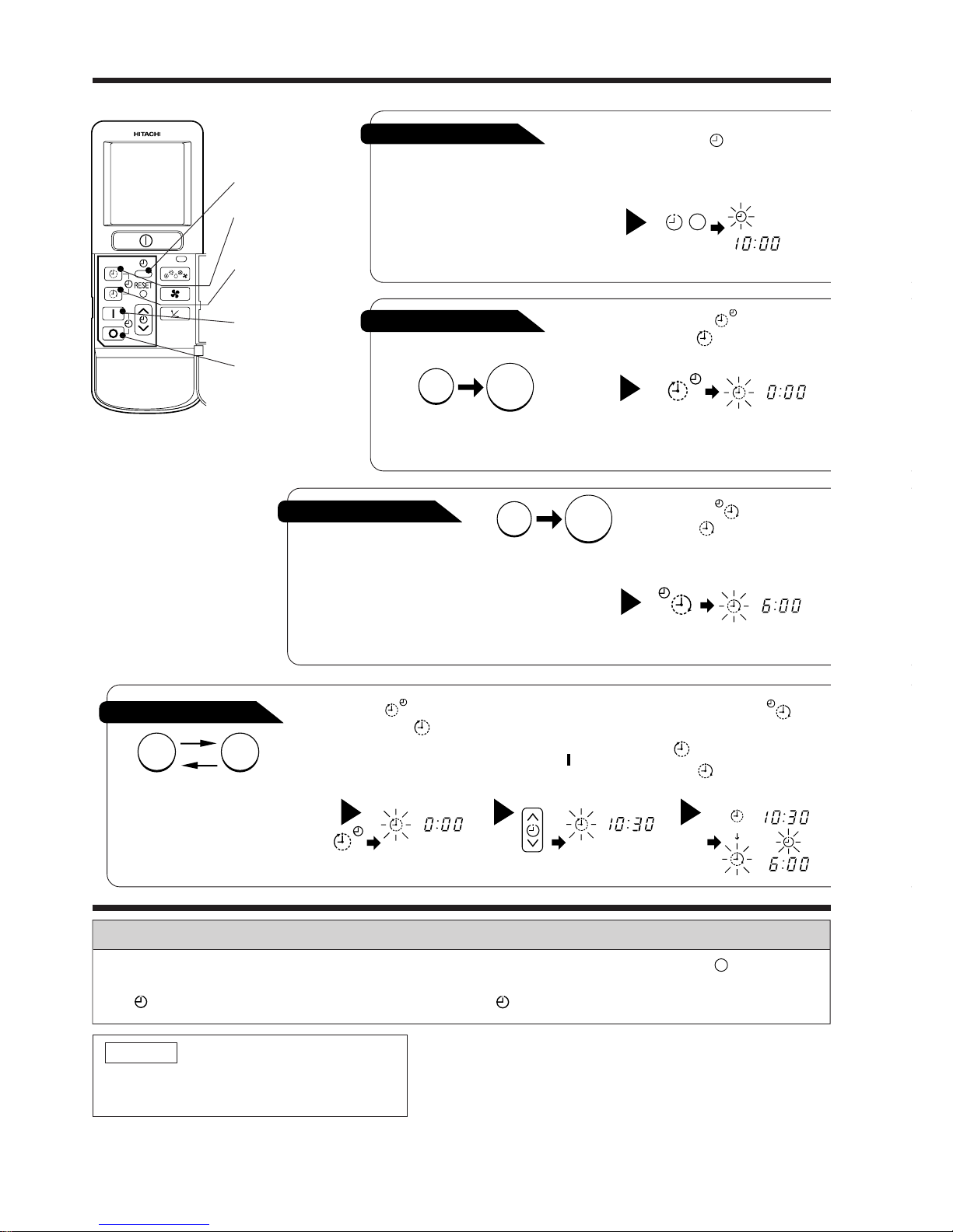
HOW TO SET THE TIMER
ON/OFF-Timer
● The device will turn on (off) and off
(on) at the designated times.
● The switching occurs first at the
preset time that comes earlier.
● The arrow mark appearing on the
display indicates the sequence of
switching operations.
1
Press the (ON-OFF)
button so that the (OFF)
mark blinks.
OFF-Timer
You can set the device to turn off
at the preset time.
After you change the
batteries;
How to Cancel Reservation
Point the signal window of the remote controller toward the indoor unit, and press the (CANCEL)
button.
The (RESERVED) sign goes out with a beep and the (TIMER) lamp turns off on the indoor unit.
1
Set the (TIME) button.
1
Press the (OFF-TIMER)
button. The (OFF) mark blinks
on the display.
1
Press the (ON-TIMER)
button the (ON) mark blinks
on the display.
2
Set the turn-off time
with the TIMER control
button.
Press the (RESERVE)
button.
3
Press the (ON-
TIMER) button so that the
(OFF) mark lights and
the
(ON) mark blinks.
NOTE
You can set only one of the OFF-timer,
ON-timer and ON/OFF-timer.
ON-Timer
Time
● The device will turn on
at the designated times.
TIME
OFF TIMER
ON TIMER
RESERVE
CANCEL
AM
PM
STOP
Start
AM
Start
Stop
AM
Start Stop
PM
PM
AM
PM
Page 20
– 19 –
3
Point the signal window of the remote controller toward the indoor unit, and
press the (RESERVE) button.
The
(OFF) mark starts lighting instead of flashing and the sign (RESERVED)
lights. A beep occurs and the (TIMER) lamp lights on the indoor unit.
● The time indication will disappear
automatically in 10 second.
● To check the current time setting,
press the (TIME) button twice.
The setting of the current time is
now complete.
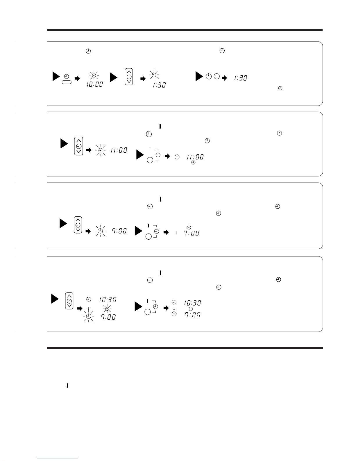
● The timer may be used in three ways: off-timer, on-timer, and ON/OFF (OFF/ON)-timer. Set
the current time at first because it serves as a reference.
● As the time settings are stored in memory in the remote controller, you only have to press
the
(RESERVE) button in order to use the same settings next time.
2
Press the
(TIME) button.
3
Set the current time with the
TIMER control button.
Example: The current time is 1:30 p.m.
2
Set the turn-off time with the
TIMER control button.
The setting of turn-off time is now complete.
Example: The device will turn off at 11:00p.m.
Example:
The device will turn on at 7:00 a.m.
The setting of the turn-on time is now complete.
4
Set the turn-on time with the
TIMER control button.
5
Point the signal window of the remote controller toward the indoor unit, and
press the (RESERVE) button.
The
(ON) mark starts lighting instead of flashing and the (RESERVED)
sign lights. A beep occurs and the
(TIMER) lamp lights on the indoor unit.
3
Point the signal window of the remote controller toward the indoor unit, and
press the (RESERVE) button.
The
(ON) mark starts lighting instead of flashing and the (RESERVED)
sign lights. A beep occurs and the (TIMER) lamp lights on the indoor unit.
2
Set the turn-on time with the
TIMER control button.
Example:
The device will turn off at 10:30 p.m. and it will be turned on
at 7:00 a.m.
The settings of the turn-on/off times are now complete.
4
Press the (TIME) button again.
The time indication starts lighting
instead of flashing.
AM
PM
AM
PM
AM
PM
AM
PM
PM
AM
PMPMPM
PM
PMPMPM
PM
AMAMAM
AM
Page 21
– 20 –
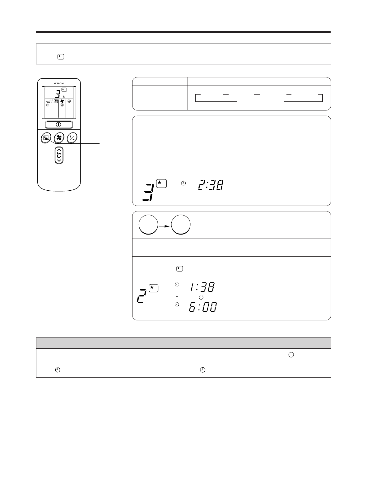
HOW TO SET THE SLEEP TIMER
Set the current time at first if it is not set before (see the pages for setting the current time). Press
the (SLEEP) button, and the display changes as shown below.
1
Set the ON-timer.
Mode
Sleep timer
Indication
1 hour 2 hours 3 hours 7 hours
Sleep timer off
44 44
1
Sleep Timer: The device will continue working for the designated
number of hours and then turn off.
Point the signal window of the remote controller toward the indoor
unit, and press the SLEEP button.
The timer information will be displayed on the remote controller.
The TIMER lamp lights with a beep from the indoor unit. When the
sleep timer has been set, the display indicates the turn-off time.
Example: If you set 3 hours sleep
time at 11:38 p.m., the turn-off
time is 2:38 a.m.
2
Press the (SLEEP) button and set the sleep timer.
The device will be turned off by the sleep
timer and turned on by on-timer.
How to Cancel Reservation
Point the signal window of the remote controller toward the indoor unit, and press the (CANCEL)
button.
The (RESERVED) sign goes out with a beep and the (TIMER) lamp turns off on the indoor unit.
For heating:
In this case, the device will turn off
in 2 hours (at 1:38 a.m.) and it will
be turned on 6:00 next morning.
H
AM
H
AM
AM
Sleep
timer
Start
SLEEP
Page 22
– 21 –
HOW TO EXCHANGE THE BATTERIES IN THE REMOTE CONTROLLER
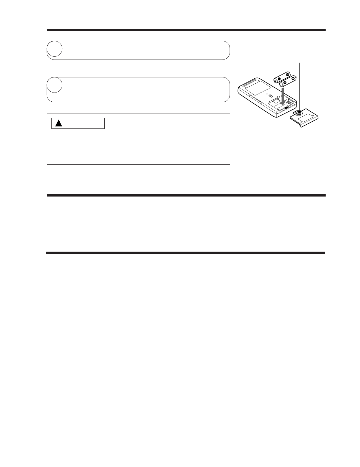
1
Remove the cover as shown in the figure and take out the
old batteries.
=
2
Install the new batteries.
The direction of the batteries should match the marks in the
case.
1. Do not use new and old batteries, or different kinds of batteries
together.
2. Take out the batteries when you do not use the remote controller
for 2 or 3 months.
CAUTION
!
Push and pull to the
direction of arrow
CIRCUIT BREAKER
When you do not use the room air conditioner, set the circuit breaker to “OFF”.
TEMPORARY SWITCH
If the remote controller does not work due to battery failure, press this switch to start and stop operation.
● This temporary operation will be at the setting made most recently. (The unit will immediately go into
automatic operation once power is switched on.)
Page 23

– 22 –
Suitable Room Temperature Install curtain or blinds
Ventilation Effective Usage Of Timer
Do Not Forget To Clean The Air Filter
Please Adjust Suitable Temperature
For Baby And Children
Warning
Freezing temperature
is bad for health and a
waste of electric power.
!
It is possible to
reduce heat
entering the
room through
windows.
At night, please use the “OFF or ON timer
operation mode”, together with your wake up
time in the morning. This will enable you to
enjoy a comfortable room temperature. Please
use the timer effectively.
Dusty air filter will reduce the air volume and
the cooling efficiency. To prevent from wasting
electric energy, please clean the filter every 2
weeks.
Please pay attention to the room temperature
and air flow direction when operating the unit
for baby, children and old folks who have
difficulty in movement.
Caution
Do not close the room for a long period of
time. Occasionally open the door and windows
to allow the
entrance of
fresh air.
!
THE IDEAL WAYS OF OPERATION
Page 24
– 23 –
FOR USER’S INFORMATION
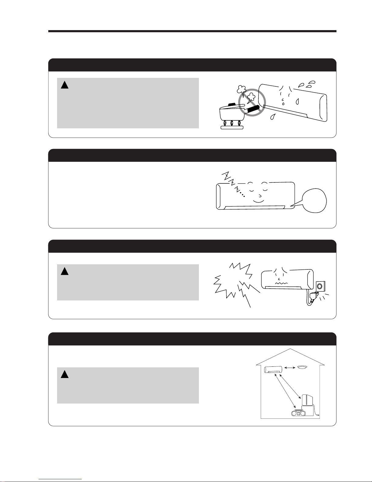
The Air Conditioner And The Heat Source In The Room
Not Operating For A Long Time
When Lightning Occurs
Caution
If the amount of heat in the room is above the cooling
capability of the air conditioner (for example: more
people entering the room, using heating equipments
and etc.), the preset room temperature cannot be
achieved.
!
When the indoor unit is not to be used for a long
period of time, please switch off the power from the
mains. If the power from mains remains “ON”, the
indoor unit still consumes about 8W in the operation
control circuit even if it is in “OFF” mode.
Warning
To protect the whole unit during lightning, please
stop operating the unit and remove the plug from the
socket.
!
OFF
Interference From Electrical Products
Caution
To avoid noise interference, please place the indoor
unit and its remote controller at least 1m away from
electrical products.
!
Inverter-type
fluorescent
lamp.
To prevent
interference,
place at least
1m away.
TV
Page 25

– 24 –
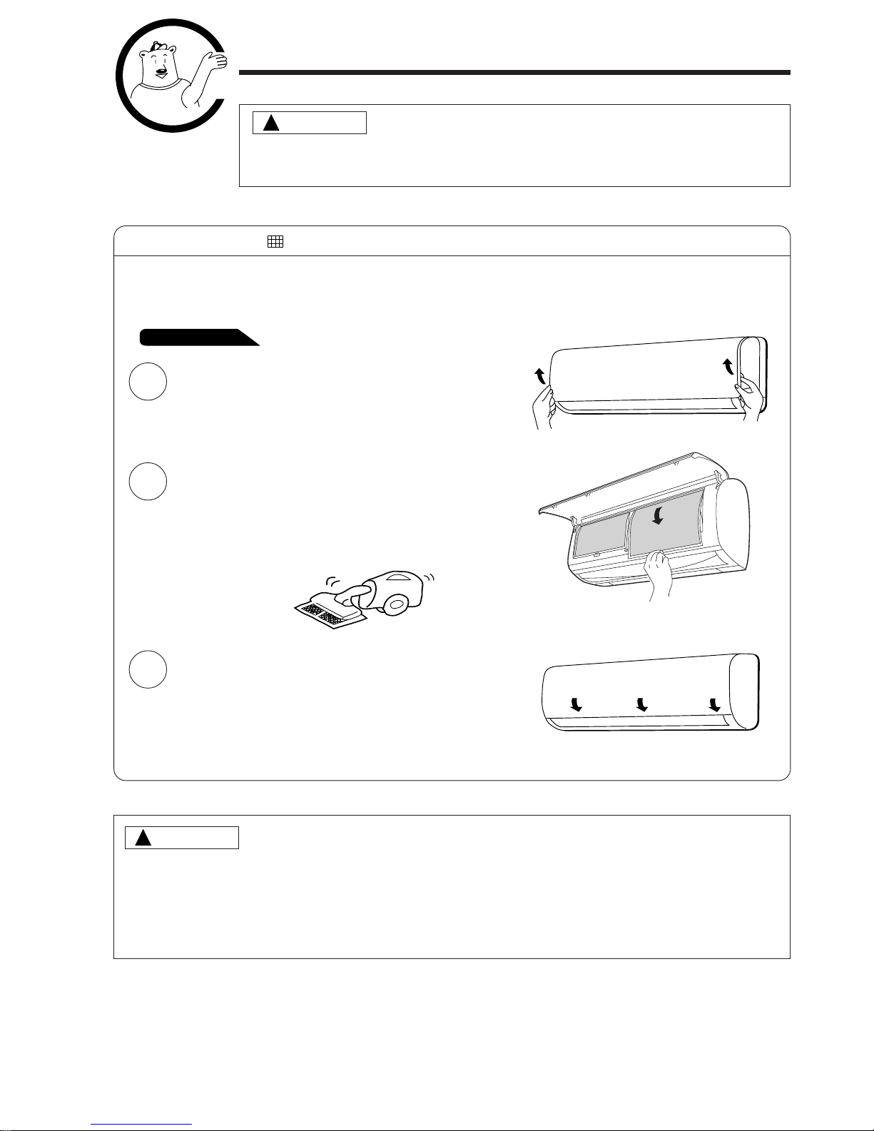
ATTACHING THE AIR CLEANSING FILTERS
1
Open the front panel.
● Pull up the front panel by holding it at both sides
with both hands.
2
Remove the filter.
● Push upward to release the claws and pull out the
filter.
3
Attaching the air cleansing filters to the filter.
● Attach the air cleansing filters to the frame by gently
compress its both sides and release after insertion
into filter frame.
4
Attach the filters.
● Attach the filters by ensuring that the surface written
“FRONT” is facing front.
● After attaching the filters, push the front panel at
three arrow portion as shown in figure and close it.
Cleaning and maintenance must be carried out only by qualified service personal. Before cleaning,
stop operation and switch off the power supply.
CAUTION
CAUTION
Do not bend the air cleansing
filter as it may cause damage to
the structure.
NOTE
● In case of removing the air cleansing filters, please follow the above procedures.
● The cooling capacity is slightly weakened and the cooling speed becomes slower when the air cleansing
filters are used. So, set the fan speed to "HIGH" when using it in this condition.
● Do not operate the air conditioner without filter. Dust may enter the air conditioner and fault may occur.
Claws
(4 places)
!
!
Page 26
– 25 –
MAINTENANCE
Cleaning and maintenance must be carried out only by qualified service personal.
Before cleaning, stop operation and switch off the power supply.
1. AIR FILTER
Clean the air filter, as it removes dust inside the room. In case the air filter is full of dust, the air flow
will decrease and the cooling capacity will be reduced. Further, noise may occur. Be sure to clean the
filter following the procedure below.
CAUTION
1
Open the front panel and remove the filter
● Gently lift and remove the air cleansing filter
from the air filter frame.
2
Vacuum dust from the air filter and air cleansing
filter using vacuum cleaner. If there is
too much dust, air filter only rinse under running
tap water and gently brush it with soft bristle
brush. Allow filters to dry in shade.
3
● Re-insert the air cleansing filter to the filter
frame. Set the filter with “FRONT” mark facing
front, and slot them into the original state.
● After attaching the filters, push the front panel
at three arrow portions as shown in figure
and close it.
CAUTION
● Do not wash with hot water at more than 40°C. The filter may shrink.
● When washing it, shake off moisture completely and dry it in the shade; do not expose it directly to
the sun. The filter may shrink.
● Do not use detergent on the air cleansing filter as some detergent may deteriorate the filter electrostatic
performance.
PROCEDURE
!
!
Page 27
– 26 –
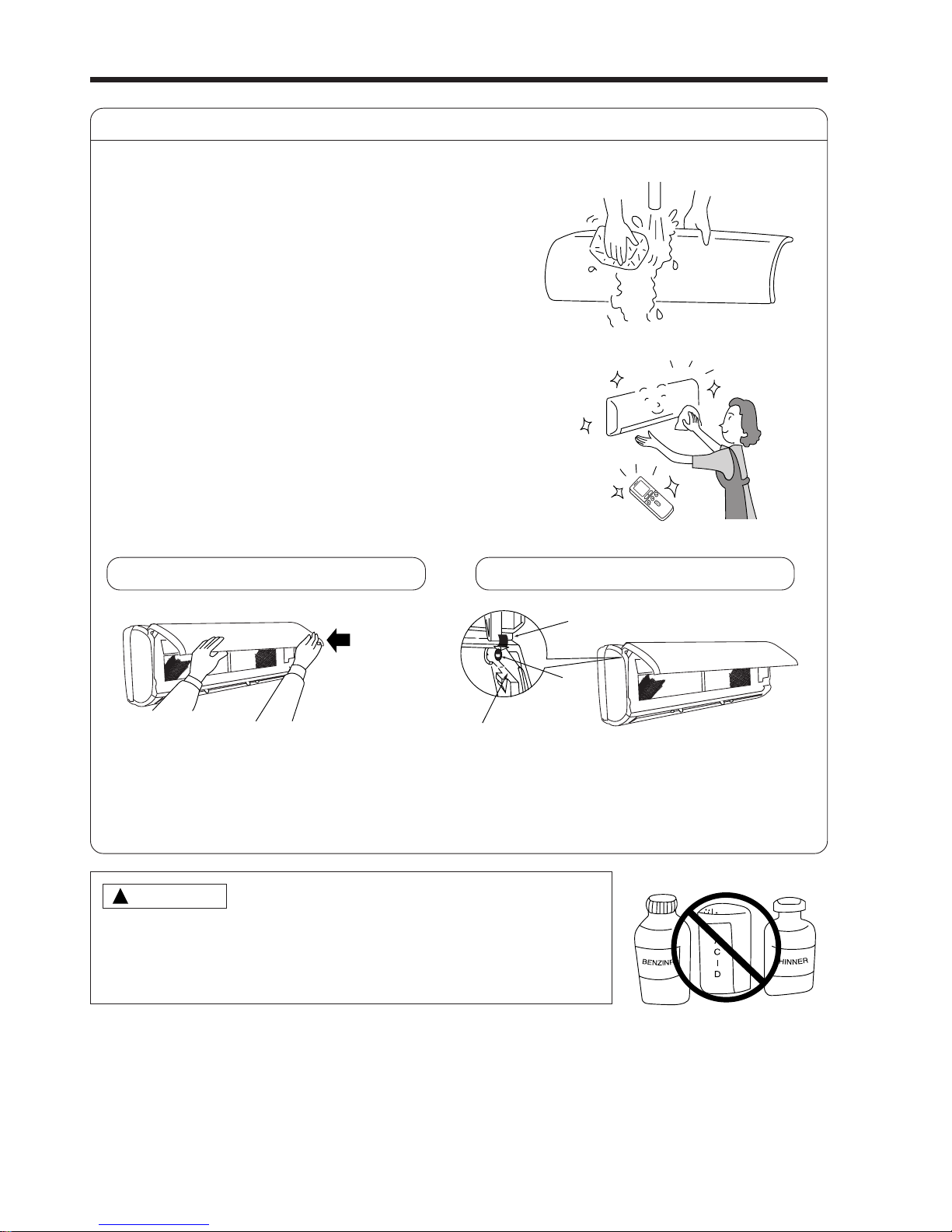
2. Washable Front Panel
● Remove the front panel and wash with clean
water.
Wash it with a soft sponge.
After using neutral detergent, wash thoroughly
with clean water.
● When front panel is not removed, wipe it with
a soft dry cloth. Wipe the remote controller
thoroughly with a soft dry cloth.
● Wipe the water thoroughly.
If water remains at indicators or signal
receiver of indoor unit, it causes trouble.
Method of removing the front panel.
Be sure to hold the front panel with both hands
to detach and attach it.
!
CAUTION
● Do not splash or direct water to the body of the unit when cleaning
it as this may cause short circuit.
● Never use hot water (above 40°C), benzine, gasoline, acid, thinner or
a brush, because they will damage the plastic surface and the coating.
Removing the Front Panel
● When the front panel is fully opened with
both hands, push the right arm to the inside
to release it, and while closing the front panel
slightly, put it out forward.
Attaching the Front Panel
● Move the projections of the left and right
arms into the Flanges in the unit and
securely insert them into the holes.
Arm
Projection
Hole
Flange
Page 28
– 27 –
1
2
3
REGULAR INSPECTION
PLEASE CHECK THE FOLLOWING POINTS BY QUALIFIED SERVICE PERSONAL EITHER
EVERY HALF YEARLY OR YEARLY. CONTACT YOUR SALES AGENT OR SERVICE SHOP.
Is the earth line disconnected or broken?
Is the mounting frame seriously affected by rust and is the
outdoor unit tilted or unstable?
Is the plug of power line firmly plugged into the socket?
(Please ensure no loose contact between them).
Cleaning and maintenance must be carried out only by qualified service personal. Before cleaning,
stop operation and switch off the power supply.
!
CAUTION
Confirm
3. MAINTENANCE AT BEGINNING OF LONG OFF PERIOD
● Running the unit setting the operation mode to
(FAN) and the fan speed to HI for about half
a day on a fine day, and dry the whole of the
unit.
● Switch off the power plug.
Air
Blow
Page 29

– 28 –
AFTER SALE SERVICE AND WARRANTY
WHEN ASKING FOR SERVICE, CHECK THE FOLLOWING POINTS.
When it does not operate
● Is the fuse all right?
● Is the voltage extremely high or low?
● Is the circuit breaker “ON”?
● Is the setting of operation mode different from other indoor
units?
● Is the air filter blocked with dust?
● Does sunlight fall directly on the outdoor unit?
● Is the air flow of the outdoor unit obstructed?
● Are the doors or windows opened, or is there any source of
heat in the room?
● Is the set temperature suitable?
● Are the air inlets or air outlets of indoor and outdoor units
blocked?
● Is the fan speed “LOW” or “SILENT”?
CONDITION CHECK THE FOLLOWING POINTS
Notes
● In quiet operation or stopping the operation, the following phenomena
may occassionally occur, but they are not abnormal for the operation.
(1) Slight flowing noise of refrigerant in the refrigerating cycle.
(2) Slight rubbing noise from the fan casing which is cooled and then
gradually warmed as operation stops.
● The odor will possibly be emitted from the room air conditioner because
the various odor, emitted by smoke, foodstuffs, cosmetics and so on,
sticks to it. So the air filter and the evaporator regularly must be cleaned
to reduce the odor.
●
Please contact your sales agent immediately if the air conditioner still fails to operate normally after the above
inspections. Inform your agent of the model of your unit, production number, date of installation. Please also
inform him regarding the fault.
●
Power supply shall be connected at the rated voltage, otherwise the unit will be broken or could not reach the
specified capacity.
When it does not cool well
When it does not hot well
If the remote controller is
not transmitting a signal.
● Do the batteries need replacement?
● Is the polarity of the inserted batteries correct?
Remote controller
display is dim or blank.)
NOTE:
● If the supply cord is damaged, it must be replaced by the special cord obtainable at authorized
service parts centers.
● On switching on the equipment, particularly when the room light is dimmed, a slight brightness fluctuation
may occur. This is of no consequence.
The conditions of the local Power Supply Companies are to be observed.
Page 30

– 29 –
CONSTRUCTION AND DIMENSIONAL DIAGRAM
Note:
1. Service space (free space needed for servicing) is 200mm on the right, 100mm on the left and 50mm on top.
2. The wide and narrow pipes must be thermally insulated.
3. Piping length is within 30m
4. Height different of the piping between the indoor unit and the outdoor unit should be within 20m.
5. Power supply cord length is about 2m
6. Connecting cable 2.5mm dia. x 3 (AB Line), 1.6mm dia. x 2 (CD Line) is used for the connection.
Unit : mm
Wireless remote controller
147
56 17.5
About
380
Viewed from back
(bottom direction pipe
lead-out)
D
C
B
A
L
N
D
C
B
A
Indoor Unit
Outdoor Unit
Connecting
Cord
Power
supply
cord
MODEL RAS-70YH7
When piping is drawn
horizontally, exchange
the drain hose for the
drain cap.
Front panel
Suction grill
245
70
8
60
Page 31

– 30 –
MODEL RAC-70YH7
Handle
Air suction
grille
16874
26 850
957
81
800
96
169.5
788
1010
10
320
340
Air outlet
340
2022 298
201
Handle
Holes for anchor bolt
(2-ø12)
Fixing hole
507 198
57
12
37
Notch for anchor bolt
(2-ø12 Notchs)
More than
More than
More than
100
More than
700
200
100
Service space
Page 32

– 31 –
MAIN PARTS COMPONENT
THERMOSTAT (Room Temperature Thermistor)
Thermostat Specifications
INDOOR FAN MOTOR
Fan Motor Specifications
CONNECTION
TEMPERATURE
°C (°F)
INDICATION
16
INDICATION
24
INDICATION
32
MODEL RAS-70YH7
THERMOSTAT MODEL IC
OPERATION MODE COOL HEAT
ON 15.6 (60.1) 20.0 (68.0)
OFF 15.3 (59.5) 20.7 (69.3)
ON 23.6 (74.5) 28.0 (82.4)
OFF 23.3 (73.9) 28.7 83.7)
ON 31.6 (88.9) 36.0 (96.8)
OFF 31.3 (88.3) 36.7 (98.1)
M
RED
BLK
WHT
YEL
BLU
100 ~ 322V
15V
0V
0 ~ 6.5V
FG
MODEL
RAS-70YH7
POWER SOURCE DC: 100 ~ 322V
OUTPUT 30W
(Control circuit built in)
BLU : BLUE YEL : YELLOW BRN : BROWN WHT : WHITE
GRY : GRAY ORN : ORANGE GRN : GREEN RED : RED
BLK : BLACK PNK : PINK VIO : VIOLET
COIL
MODEL
RAC-70YH7
POWER SOURCE DC: 120 ~ 380V
OUTPUT (W) MAX 47
OUTDOOR FAN MOTOR
Fan Motor Specifications
ITEM
M
WHITE (V)
BLACK (W)
M
M
RED (U)
RESISTANCE VALUE ( ) 20°C 2M U-V 35 ± 2.5 V-W 35 ± 2.5 W-U 35 ± 2.5
Page 33

– 32 –
COMPRESSOR MOTOR
Compressor Motor Specifications
CAUTION
When the Air Conditioner has been operated for a long time with the capillary tubes clogged or crushed
or with too little refrigerant, check the color of the refrigerant oil inside the compressor. If the color has been
changed conspicuously, replace the compressor.
V/R (YELLOW)
W/S (RED)
U/C (WHITE)
MODEL
COMPRESSOR MODEL
PHASE SINGLE
RATED VOLTAGE AC 220 ~ 240 V
RATED FREQUENCY 50/60 Hz
POLE NUMBER 4
CONNECTION
20°C
(68°F)
75°C
(167°F)
( )
RESISTANCE VALUE
RAC-70YH7
JU1015D9
2M = 1.2984
U
V
W
WHITE
M
M
M
YELLOW
RED
2M = 1.7671
Page 34

– 33 –
WIRING DIAGRAM
MODEL RAS-70YH7 / RAC-70YH7
BLU : BLUE YEL : YELLOW BRN : BROWN WHT : WHITE
GRY : GRAY ORN : ORANGE GRN : GREEN RED : RED
BLK : BLACK PNK : PINK VIO : VIOLET IVO : IVORY
Page 35

– 35 –
CIRCUIT DIAGRAM
Remote Control
Page 36

– 37 –
CIRCUIT DIAGRAM
MODEL RAS-70YH7
Page 37

– 39 –
CIRCUIT DIAGRAM
MODEL RAC-70YH7
Page 38

– 41 –
PRINTED WIRING BOARD LOCATION DIAGRAM
MODEL RAS-70YH7
MAIN P.W.B.
Marking on P.W.B
COMPONENT SIDE
SOLDERING SIDE
RECEIVING P.W.B.
Marking on P.W.B
Page 39

– 42 –
MODEL RAC-70YH7
P.W.B. MAIN
Page 40

– 43 –
P.W.B. IPM-BOARD
P.W.B. NF-BOARD
Page 41

– 44 –
BLOCK DIAGRAM
MODEL RAS-70YH7/RAC-70YH7
1ø, 50/60Hz, 220~240V
(AX-8X10)
FM
Outdoor DC
Fan Motor
Page 42

– 45 –
51.
53.
53.
55.
57.
49.
29. 66
23
25
25
25
25
Page 43

– 47 –
Table 1 Mode data file
LABEL NAME VALUE
WMAX
WMAX2 5700 min
–1
WSTD 5400 min
–1
WBEMAX 4000 min
–1
CMAX 5200 min
–1
CSTD 4900 min
–1
CKYMAX 4000 min
–1
CJKMAX 4000 min
–1
CBEMAX 2300 min
–1
WMIN 1200 min
–1
CMIN 1200 min
–1
STARTMC 60 Seconds
DWNRATEW 100%
DWNRATEC 100%
SHIFTW 0.00°C
SHIFTC 1.00°C
CLMXTP 30.00°C
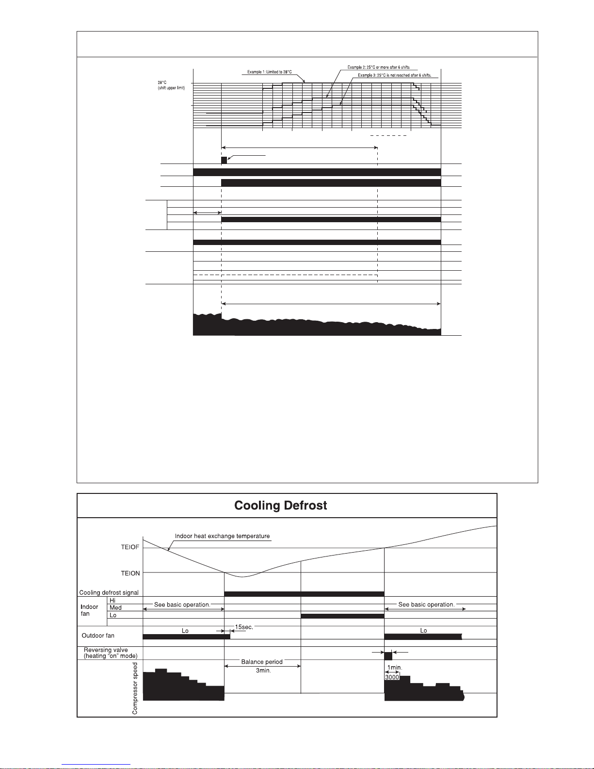
YNEOF 25.00°C
TEION 2.00°C
TEIOF 9.00°C
SFTDSW 0.66°C
DFTIM_OTP0 50 Minutes
DFTIM_OTP10 50 Minutes
DFTIM_OTP5 60 Minutes
STARCPL 1600 min
–1
RAS-70YH7
5700 min
–1
Page 44

– 49 –
Reversing valve (heating on mode)
NOTE (9)
NOTE (5)
Dash period
Silent
1
Notes:
(1) Condition for entering into Cool Dashed mode. When fan set to “Hi” or “Auto mode” and temperature difference between indoor temperature and set temperature has a
corresponding compressor rpm (calculated value in Table 2) larger than CMAX.
(2) Cool Dashed will release when i) a maximum 25 minutes is lapsed and ii) room temperature is lower than set temperature –3°C (thermo off) and iii) when room temperature
has achieved setting temperature –1°C then maximum Cool Dashed time will be revised to 20 minutes. And iv) indoor fan is set to Lo and Med fan mode and v) change operation
mode.
(3) During Cool Dashed operation, thermo off temperature is set temperature (with shift value) –3°C. After thermo off, operation continue in Fuzzy control mode.
(4) Compressor minimum “ON” time and “OFF” time is 3 minutes.
(5) During normal cooling mode, compressor maximum rpm CMAX will maintain for 60 minutes if indoor temperature is lower than CLMXTP. No time constrain if indoor temperature
is higher than CLMXTP.
(6) When fan is set to “Hi”, compressor rpm will be limited to CKYMAX.
(7) When fan is set to “Med”, compressor rpm will be limited to CJKMAX.
(8) When fan is set to “Lo”, compressor rpm will be limited to CBEMAX.
(9) During Cool Dashed, when room temperature reaches set temperature –1°C compressor rpm is actual rpm x DWNRATEC.
Temperature Calculated
difference compressor rpm
1.66 2265 min
–1
2 2435 min
–1
2.33 2600 min
–1
2.66 2765 min
–1
3 2935 min
–1
3.33 3100 min
–1
3.66 3265 min
–1
4 3435 min
–1
4.33 3600 min
–1
4.66 3765 min
–1
5 3935 min
–1
5.33 4100 min
–1
5.66 4265 min
–1
6 4435 min
–1
6.33 4600 min
–1
6.66 4765 min
–1
7 4935 min
–1
7.33 5100 min
–1
7.66 5265 min
–1
8 5435 min
–1
8.33 5600 min
–1
8.66 5765 min
–1
9 5935 min
–1
9.33 6100 min
–1
9.66 6265 min
–1
10 6435 min
–1
10.33 6600 min
–1
10.66 6765 min
–1
11 6935 min
–1
Table 2 ∆TCMAX
Note:
1. See the data in Table 1 on
page 45 for each constant in
capital letters in the diagrams.
Page 45
– 51 –
Notes:
(1) The sleep operation starts when the sleep key is pressed.
(2) When the sleep key is set, the maximum compressor speed is limited, and the indoor fan is set to “sleep Lo”.
(3) 30 minutes after the sleep key is set, the sleep shift of temperature starts, and upper shift is made at least 6 times.
If 25˚C is not reached after 6 shifts, shifts repeat unit 25˚C is reached.
(4) The sleep shift upper value of set temperature is 28˚C.
(5) After 6 hours, a shift down to the initial set temperature is made at a rate of 0.33˚C/5 min.
(6) If the operation mode is changed during sleep operation, the set temperature is cleared, and shift starts from the point
when switching is made.
(7) The indoor fan speed does not change even when the fan speed mode is changed.
(8) When operation is stopped during sleep operation, the set temperature when stopped, as well as the time, continue
to be counted.
(9) If the set time is changed during sleep operation, all data including set temperature, time, etc. is cleared and restarted.
(10) If sleep operation is canceled by the cancel key or sleep key, all data is cleared.
Cooling Sleep Operation
Compressor speed
Horizontal air
deflector
Shut
Horizontal
Facing down
Maximum speed
Indoor
fan
Outdoor fan
Timer lamp
Operation lamp
Sleep key
(Cooling/dehumidifying set
temperature = Remote control set
temperature (+) SHIFTC)
Final set temperature
(Cooling/dehumidifying set
temperature (+) sleep shift)
Set to 7 hours
0.5hr
1.5hr
3hr
P1
2.5hr 3.5hr 6hr 7hr
Hi
See basic operation
Med
Lo
Silent (Sleep)
Lo
10 mins
Silent (Sleep)
Page 46

– 53 –
Page 47

– 55 –
1.33ßC.
SFTDSW
0.66ßC.
Fan speed set to "auto"
1 min.
Hi
Lo Hi Hi Hi
ultra Hi
Basic Heating Operation
Start
Stop Start Start StopStop
Thermo
OFF
Thermo
OFF
Heating set temperature
(remote control set temperature
(+))
Start/stop switch
Thermo judgment
Indoor
fan
Ultra-Hi
Hi
Med
Lo
Silent (Sleep)
Ultra-Lo
Operation lamp
Max.
Rating
3000
0
Compressor speed
Outdoor fan
Reversing valve (heating "on" model)
Thermo OFF
Dash period
NOTE (5)
TWMAX
Wtd
Defrost signal
Preheating judgment
30sec. 30sec.
10sec.
15sec. 15sec.
15sec. 15sec. 15sec.
10sec.
15sec.
15sec.
150sec. Delay
150sec. Delay150sec. Delay
3min.
Max. 3 min.
Preheating released
Control by
heat exchanger temperature
Control by
heat exchanger temperature
15sec.
Control by
heat exchanger temperature
Control by
heat exchanger temperature
Control by
heat exchanger temperature
18ßC
10sec.
30sec. 30sec.
10sec.
30sec. 30sec.30sec. 30sec. 30sec. 30sec.
10sec.
Preheat released
WMIN
(WSTD)
(WMAX)
NOTE (11)
WMAX2
Notes:
(1) Condition for entering into Hot Dashed mode. When fan set to “Hi” or “Auto mode” and i) Indoor temperature is lower than 18°C, and ii) outdoor temperature is lower than 10°C,
and iii) Temperature difference between indoor temperature and set temperature has a corresponding compressor rpm (calculated value in Table 3) larger than WMAX.
(2) Hot Dashed will release when i) Room temperature has achieved the set temperature + SFTDSW. ii) Thermo off.
(3) During Hot Dashed operation, thermo off temperature is set temperature (with shift value) +3°C. After thermo off, operation continue in Fuzzy control mode.
(4) Compressor minimum “ON” time and “OFF” time is 3 minutes.
(5) During normal heating mode, compressor maximum rpm WMAX will maintain for 120 minutes if indoor temperature is higher than 18°C. No time limit constrain if indoor temperature
is lower than 18°C and outdoor temperature is lower than 2°C.
(6) During Hotkeep or Defrost mode, indoor operation lamp will blink at interval of 3 seconds “ON” and 0.5 second “OFF”.
(7) When heating mode starts, it will enter into Hotkeep mode if indoor heat exchanger temperature is lower than YNEOF + 0.33°C.
(8) When fan is set to “Med” or “Lo”, compressor rpm will be limited to WBEMAX.
(9) In “Ultra-Lo” fan mode, if indoor temperature is lower than 18°C, indoor fan will stop. If indoor temperature is higher than 18°C + 0.33°C, fan will continue in “Ultra-Lo” mode.
During Hotkeep or Defrost mode, fan will continue in “Ultra-Lo” mode.
(10) During Hot Dashed or outdoor temperature is lower than –5°C, compressor rpm is WMAX2.
(11) During Hot Dashed, when room temperature reaches set temperature + SFTDSW compressor rpm is actual rpm x DWNRATEW.
Temperature Calculated
difference compressor rpm
1.66 1965 min
–1
2 2135 min
–1
2.33 2300 min
–1
2.66 2465 min
–1
3 2635 min
–1
3.33 2800 min
–1
3.66 2965 min
–1
4 3135 min
–1
4.33 3300 min
–1
4.66 3465 min
–1
5 3635 min
–1
5.33 3800 min
–1
5.66 3965 min
–1
6 4135 min
–1
6.33 4300 min
–1
6.66 4465 min
–1
7 4635 min
–1
7.33 4800 min
–1
7.66 4965 min
–1
8 5135 min
–1
8.33 5300 min
–1
8.66 5465 min
–1
9 5635 min
–1
9.33 5800 min
–1
9.66 5965 min
–1
10 6135 min
–1
10.33 6300 min
–1
10.66 6465 min
–1
11 6635 min
–1
Table 3 ∆TWMAX
Notes:
1. See the data in Table 1 on
page 47 for each constant in
capital letters in the diagrams.
Page 48

– 57 –
DFTIM_OTP5
DFTIM_OTP10
DFTIM_OTP0
DFTIM_OTP0.
DFTIM_OTP0
1. Refer to the Table 1 Mode data file on page 47 for the constants expressed by capital
alphabet letters in the drawing.
Page 49

– 59 –
REFRIGERATING CYCLE DIAGRAM
MODEL RAS-70YH7/RAC-70YH7
INDOOR UNIT
OUTDOOR UNIT
COOLING, DEHUMIDIFYING, DEFROSTING
OUTDOOR UNIT
HEATING
INDOOR UNIT
COMP
S-TANK
(5/8")
5S VALV E
SILENCER
(1/4")
2S VALV E
EXPANSION VALVE
STRAINER
STRAINER
COND
REVERSING
VALV E
COMP
S-TANK
(5/8")
5S VALV E
(1/4")
2S VALV E
EXPANSION VALVE
HEX
THERMISTOR
STRAINER
STRAINER
COND
REVERSING
VALV E
SILENCER
HEX
THERMISTOR
Page 50

– 60 –
OPERATING SPECIFICATION
REFERENCE
OPERATION OPERATION MODE AIR DEFLECTOR
PRESENT CONDITION
KEY INPUT
THERMO. ON
(INTERNAL FAN
ON)
THERMO. ON
(INTERNAL FAN
OFF)
MAIN SWITCH
ON
MAIN SWITCH
OFF
CHANGE OF
OPERATION
STOP
DURING
OPERATION
DURING
OPERATION
STOP
DURING
OPERATION
DURING
OPERATION
EACH MODE
AUTO COOL
COOL
FAN
AUTO DRY
DRY
AUTO HEAT
HEAT
CIRCULATOR
AUTO DRY
DRY
AUTO HAET
HEAT
CIRCULATOR
COOL
FAN
DRY
HEAT
CIRCULATOR
EACH MODE
EACH MODE
STOP SWINGING AND MODE BECOMES INITIALIZING
CONDITION.
INITIALIZING CONDITION OF EACH MODE.
ONE SWING (CLOSING AIR DEFLECTOR)
1 DOWNWARD
2 UPWARD
INITIALIZE
1 DOWNWARD
INITIALIZE
1 DOWNWARD
2 UPWARD
STOP AT THE MOMENT.
START SWINGING
1 DOWNWARD
2 UPWARD
3 DOWNWARD
STOP AT THE MOMENT.
START SWINGING
1 DOWNWARD
2 UPWARD
3 DOWNWARD
STOP AT THE MOMENT.
ONE SWING (CLOSING AIR DEFLECTOR)
1 DOWNWARD
2 UPWARD
INITIALIZE AT NEXT
OPERATION.
INITIALIZE AT NEXT
OPERATION.
STOP
DURING ONE SWING
STOP
DURING SWINGING
STOP
DURING SWINGING
TEMPORARY STOP
DURING SWINGING
STOP
DURING ONE SWING
STOP
DURING ONE SWING
STOP
DURING SWINGING
DURING
INITIALIZING
STOP
DURING SWINGING
AUTO SWING FUNCTION
STOP SWINGING TEMPORARILY.
(SWING MODE IS CLEARED IF SWING COMMAND IS
TRANSMITTED DURING TEMPORARY STOP.)
START SWING AGAIN.
INPUT SIGNAL
Page 51

– 61 –
1. Reset Circuit
● The reset circuit is used to reset the program to its initial settings when the power is turned on or when the
power is recovered after a power failure.
● The micro computer is reset when the reset input is “Hi”, and operation is possible when the reset input is
“Lo”.
● The waveforms at each point when the power is turned on and off are shown in the diagrams.
● When the power is turned on, the voltages of the DC 12V line and DC 5V lines are increased. When the
voltage of DC 12V lines reaches about 7V, ZD202 is turned ON, the potential of Q201’s base rises and Q202
is turned ON. Since Q202’s collector is set to “LO” at this time, Q202 is turned OFF and the reset input of
the micro computer is set to “Lo”. The DC 5V line voltage has already become 5V at this time and the micro
computer starts operation.
● When the power is turned OFF, the voltage of the DC 12V line decreases. When it becomes about 7V, ZD202
is turned OFF, then Q201 is turned OFF, Q202 is turned ON the reset input of the micro computer is set to
“Hi’ and the micro computer is set to the reset mode.
POWER ON
12V
7V
5V
DC12V Line
DC5V Line
Base
POWER OFF
5V
Micro computer
Pin 7
12V
5V
0V
0V
Q201
C202
7
Micro computer
RES
Q202
ZD202
R205
R201
R204
R202
R203
+
C201
AX-7X30
DESCRIPTION OF MAIN CIRCUIT OPERATION
RAS-70YH7
Page 52

– 62 –
2. Buzzer Circuit
Micro computer
(AX-7X30)
BUZZER
BZ1
12V
0V
R301
Q301
B.Z
30
When the buzzer is to be activated, buzzer output pin 30 of the micro computer alternates between ON and
OFF repeatedly at 4kHz and Q301 is turned ON/OFF accordingly. A 4kHz voltage/frequency is applied to
the buzzer and the diaphragm of the buzzer vibrates to output 4kHz sound.
3. Initial setting (IC401)
The pre-heating operation start value, ratings of the compressor, maximum rotation speed, etc. are preset in
the micro computer.
4. Receive circuit
Infrared signals from the wireless remote controller are received by the light receiving unit and output after
being amplified and shaped.
87
IC401
(E 2PROM)
65
Micro computer
(AX-7X30)
26
27
R404
R403
12 4
3
5V
0V
5V
D401
45
2
1
6
3
0V
SDA
SCL
C1104
R141
R1109
0V
0V
Receiver
Unit
12V
13
Micro computer
(AX-7X30)
REMOCON I/P
Page 53

– 63 –
5. Auto Sweep Motor Circuit
18
17
16
15
7
6
5
4
8
10
IC501
12V
CN12/CN11
Auto sweep motor for
horizontal air deflectors
Rotor
0V
11
12
13
1
2
3
4
5
Fig. 5-1 Auto Sweep Motor Circuit (Horizontal air deflectors only)
● Fig. 5-1 shows the Auto sweep motor drive circuit; the signals shown in Fig. 5-2 are output from pins
– of the micro computer.
Micro computer pins
Step width
Horizontal air
deflectors: 10ms.
12345678
Horizontal air deflectors
10
11
12
13
Fig. 5-2 Micro computer Output Signals
● As the micro computer’s outputs change as shown in Fig. 5-2, the core of the auto sweep motor is excited
to turn the rotor. Table 5-1 shows the rotation angle of horizontal air deflectors.
Rotation angle per step (° )
0.0879
Time per step (ms)
10Horizontal air deflectors
Table 5-1 Auto sweep Motor Rotation
15 18
Page 54

– 64 –
6. Room Temperature Thermistor Circuit
● Fig. 6-1 shows the room temperature
thermistor circuit.
0V
Room
temperature
thermistor
0V
5V
Fig. 6-1
A
R309
C302
Micro
computer
Room
temp. input
R310
0V
Heat exchanger
temperature thermistor
0V
5V
Fig. 7-1
A
R307
C301
Micro computer
Heat
exchanger
temperature
input
R308
5
4
3
2
1
0
010
Fig. 6-2
20 30 40
Voltage at
(V)A
5
4
3
2
1
0
010
-10
Fig. 7-2
20 30 40
Voltage at
(V)A
64
63
7. Heat exchanger temperature thermistor circuit
● The voltage at A depends on the room
temperature as shown in Fig. 6-2.
● The circuit detects the indoor heat
exchanger temperature and controls
the following.
(1) Low-temperature defrosting during
cooling and dehumidifying
operation.
The voltage at A depends on the heat
exchanger temperature as shown in
Fig. 7-2.
Page 55

– 65 –
8. Temporary Switch
● The temporary switch is used to operate the air conditioner temporarily when the wireless remote control
is lost or faulty.
● The air conditioner operates in the previous mode at the previously set temperature. However, when the
power switch is set to OFF, it starts automatic operation.
0V
C601
R611
48
R609
5V
Temporary
switch
TEMPORARY SW
MICRO COMPUTER
Fig. 8-1
9. Indoor Fan Motor Feedback Circuit
● Fan motor will receive signal thru Joint Connector with VDC (Motor Drive Voltage), VCC (Motor Controller
Power Supply), VSC (RPM Instruction) motor WCC return the FG sinal under frequency RPM.
● The circuit produces fan motor drive from 340V DC supplied from the indoor unit and controls the fan
motor speed.
CAUTION 1
Indoor fan motor circuit will be connected with primary
power source line and please take care of the
electrical shock.
I O
G
0V
20V
5V
5V
15V
0V
VDC
FM
GND
VCC
VS
FG
JOINT
CONNECTOR
1
3
4
5
6
340V
R501
ZD201
IC201
Q503
Q502
Q204
PC202
PC201
R510
R504 R503
C991
C992
R502
R501
R502 R507
R509
C503
C504
R508
C505
0V
0V
0V
R234 R233
R232
C231
CAUTION 2
Please do not disconnect the fan motor connector during
running due to the high voltage supply, it will cause the
damage at fan motor and PWB.
● <Exp. of circuit wave>
JOINT
CONNECTOR
Fig. 9-1
Fig. 9-2
Page 56

– 66 –
220-240
220-240
3.15A
RAC-70YH7
Page 57

– 67 –
AC220~240V
DC260~360V
Page 58

– 68 –
C001 ~ C007, C015, C016, C026, C027, L004, L005
J25
J25
J25
J23
J58
J25
Page 59
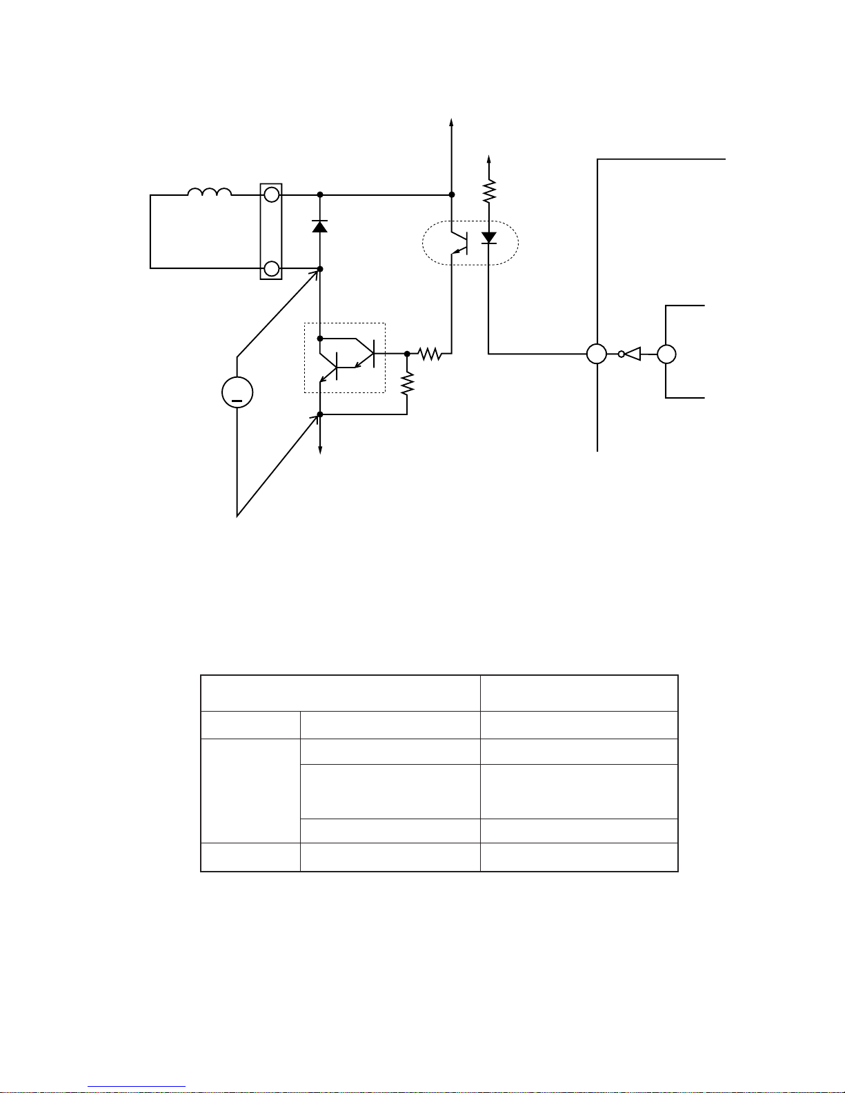
– 69 –
3. Reversing valve control circuit
● Reversing valve control circuit can switch reversing valve ON/OFF according to instruction from indoor
microcomputer depending on the operation condition shows in Table 3-1.
Voltage at each point in each operation condition is approximately as shown below when measured by
tester. (When collector voltage of Q401 is measured)
4
1
28
36
I/F 0V
Fig. 3 – 1
D401
CN2
Q401
DC voltmeter
or tester
Reversing
valve
R435
MICROCOMPUTER
PQ701
1
23
4
12V
HIC
I/F 35V
R436
V
R437
Operation condition Collector voltage of Q401
Cooling
Heating
Dehumidifying
General operation of Cooling
In normal heating operation
MAX. rotation speed instructed
by indoor microcomputer after
defrost is completed
Defrosting
Sensor dry
About 0.8V
About 35V
About 35V
About 0.8V
About 0.8V
Table 3-1
Page 60

– 70 –
Page 61

– 71 –
Page 62
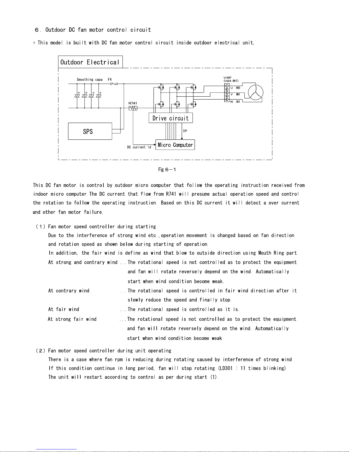
– 72 –
(3.15A Fuse)
Page 63

– 73 –
3.15A
3.15A
(DC260~360V)
Page 64

– 74 –
SERVICE CALL Q & A
COOLING MODE
DEHUMIDIFYING MODE
HEATING MODE
Q1
Q1
Q2
A1
A1
A2
A1
A2
A3
Q3
Q1
Q2
Q3
A3
Q4 A4
The compressor has stopped
suddenly during cooling
operation.
Check if indoor heat
exchanger is frosted.
Wait for 3-4 minutes
until it is defrosted.
If the air conditioner operates
in cooling mode when it is cold,
the evaporator may get frosted.
Page 65

– 75 –
AUTO FRESH DEFROSTING
NICE TEMPERATURE RESERVATION
AUTO OPERATION
Q1
Q1
Q2
Q1
Q2
A1
A1
A2
Q3
A3
A1
A2
Q3
A3
Page 66

– 76 –
Page 67

– 77 –
Page 68

– 78 –
TROUBLE SHOOTING
Page 69

– 79 –
DISCHARGE PROCEDURE AND METHOD TO STOP ENERGIZE THE POWER CIRCUIT
Page 70

– 80 –
Page 71

– 81 –
3.15A
circuit diagram
Replace fuse or P.W.B Main.
Replace P.W.Bs.
140 50
CHECKING THE INDOOR TIMER LAMP IF BLINKING 1 TIME
Page 72

– 82 –
CHECKING THE INDOOR/OUTDOOR UNIT ELECTRICAL PARTS AND REFRIGERATING CYCLE
Does the timer lamp on the indoor unit blink?
Is the compressor in the outdoor unit operating?
Does the operation lamp on the indoor unit
start to light or blink?
Remove the outdoor unit cover and
electrical parts cover, and check
self-diagnosis lamp LD301
Does LD301 blink one time ?
* Repeats 0.25-second on and
2-second off.
Blinking other than
one time
One-time blinking
Yes
Yes
Yes
Yes No
No
No
Normal
No
No
Timer
lamp
Press the service switch for 1 sec.
Does the compressor operate?
(After checking, be sure to press
the service switch to stop the
operation).
Check the refrigerating cycle.
Check the outdoor electrical parts.
Check the indoor electrical parts.
Check to see whether the Fcable is connected incorrectly
or disconnected
See Out door unit self-diagnosis lamp
lighting mode .
See Troubleshooting when the timer lamp
blinks .
Is approx. DC 33 to 37V being generated? Is the
polarity correct?
Remove the terminal cover and check the voltage
between terminal (C) and terminal (D)
Terminal C
Terminal A
Terminal B
(+35V)
Terminal D
(0V)
Page 73

– 83 –
TROUBLESHOOTING WHEN TIMER LAMP BLINKS.
Perform troubleshooting according to the number of times the indoor timer lamp and outdoor LD301 blink.
SELF-DIAGNOSIS LIGHTING MODE
No. Blinking of Timer lamp Reason for indication Possible cause
Reversing valve defective
When the indoor heat exchanger
temperature is too low in the
heating mode or it is too high in the
cooling mode.
Outdoor unit forced operation
When the outdoor unit is in forced
operation or balancing operation
after forced operation
Indoor/outdoor interface defective
When the interface signal from the
outdoor unit is interrupted.
Outdoor electrical assembly
defective.
Room thermistor or heat exchanger
thermistor is faulty
When room thermistor or heat
exchanger thermistor is opened
circuit or short circuit.
Over-current detection at the DC fan
motor
when over-current is detected at the
DC fan motor of the indoor unit.
IC401 or IC402 data reading error
When data read from IC401 or
IC402 is incorrect.
(1) Reversing valve defective
(2) Heat exchanger thermistor dis-
connected
(only in the heating mode)
(Note)
The malfunction mode is entered the
3rd time this abnormal indication
appears (read every 3 minutes).
Electrical parts in the outdoor unit
(1) Indoor interface circuit
(2) Outdoor interface circuit
Please check at the outdoor
electrical led lamp blinking (LD301)
and refer to self diagnosis lighting
mode for outdoor unit.
(1) Room thermistor
(2) Heat exchanger thermistor
(1) Indoor fan locked
(2) Indoor fan motor
(3) Indoor control P.W.B.
IC401 or IC402 abnormal
<Cautions>
(1) If the interface circuit is faulty when power is supplied, the self-diagnosis display will not be displayed.
(2) If the indoor unit does not operate at all, check to see if the F-cable is connected or disconnected.
(3) To check operation again when the timer lamp is blinking, you can use the remote control for operation
(except for mode mark 1).
1
2
3
4
5
6
7
( –– Lights for 0.5 sec. at interval of 0.5 sec..)
–– 10 times
– ––––– 3 times
– ––––––– 1 time
– –––––– 2 times
–– 13 times1
–– 9 times
–– 4 times
5 sec.
5 sec.
5 sec.
5 sec.
5 sec.
5 sec.
5 sec.
5 sec.
Page 74

– 84 –
1. Power does not come on (no operation)
Is AC 220-240V AC being generated
between terminals L and N on the
outdoor unit terminal board?
Is DC 35V being generated between
terminals C and D on the outdoor
unit terminal board?
Check the indoor/outdoor unit
connection cable, and correct any
defective section (wrong connection,
incomplete insertion reversed).
Check AC outlet and breaker, and
repair any defective part.
Check the outdoor unit power circuit,
and repair the defective section.
Is DC 35V being generated between
terminals C and D on the terminal
board?
Are control voltages (12V, 5V)
being generated normally?
Check according to the proper method
for checking the power circuit.
No No
No
No
Yes
Yes
Do the air deflectors perform initial
operation when the power supply is
turned on and off?
Check the indication P.W.B.
connection cord and light receiving
unit.
No
No
Is the microcomputer reset input
(pin 7 ) Hi ?
Replace the control P.W.B
Perform final operation check.
Check the reset circuit, and repair
any defective section.
Yes
No
Is the microcomputer clock signal
10MHz at pin
10 11
being
generated normally?
Replace the microcomputer and
oscillator.
Yes
Yes
Yes
CHECKING INDOOR UNIT ELECTRICAL PARTS
Page 75

– 85 –
2. Outdoor unit does not operate (but receives remote infrared signal)
Page 76
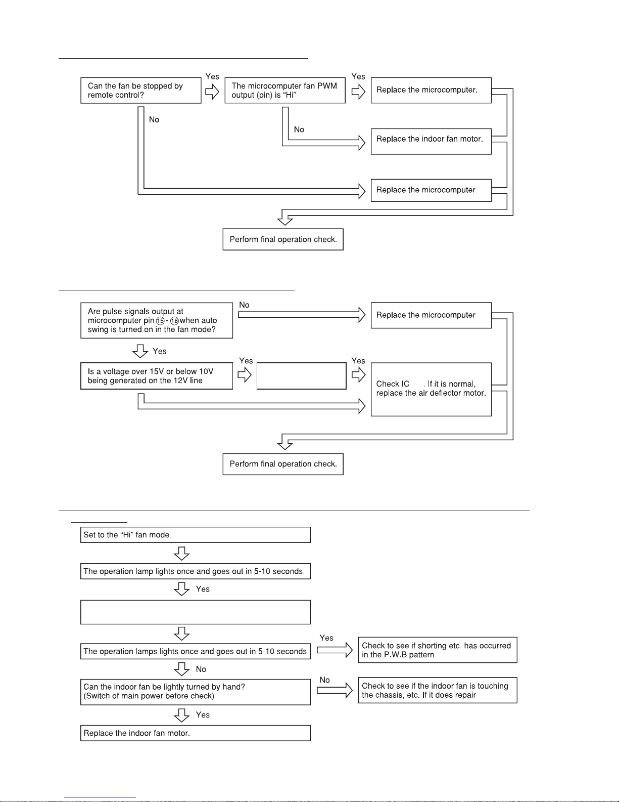
– 86 –
3. Only indoor fan does not operate (other is normal)
Check the T001 and
interface relay.
501
Disconnect joint connector at indoor fan motor and set to
the fan mode again.
4. Air deflector does not move (others are normal)
5. All systems stop from several seconds to several minutes after operation is started (all indicators
are also off)
Page 77

– 87 –
6. Check the main P.W.B (power circuit)
IC101
Is DC 35V being output
at terminals C and D?
Is DC 35V being output
between cathode and
mode of D701
Is DC 12V being supplied
accross the control side
(coil terminal) of interface relay
Replace the interface relay
D701 and C701 may be
defective
There is a defective between
the 12V output of switching
power supply and interface
relay.
Page 78

– 88 –
Has the 3.15A fuse blown?
Replace outdoor P.W.Bs.
Replace outdoor P.W.Bs.
Replace outdoor P.W.B Main.
Replace outdoor P.W.B Main.
Replace outdoor P.W.B Main
Replace outdoor P.W.B Main.
Page 79

– 89 –
test/
Replace outdoor P.W.B Main.
Replace outdoor P.W.B Main.
Replace outdoor P.W.B Main.
Replace outdoor P.W.B Main.
Page 80

– 90 –
AC220~240V
AC240V
P.W.Bs.
P.W.Bs.
Replace outdoor P.W.B Main.
P.W.Bs
Page 81

– 91 –
Replace outdoor P.W.B Main.
Replace fan motor.
Replace outdoor P.W.B Main.
Page 82

– 92 –
1. Switch OFF main power supply.
2. Short circuit between JW001 and JW002.
3. Switch ON main power supply – LD302 will blink 1 time.
4. (Within 3 minutes) Press Test/Service Switch for 1 second or more.
5. Self-diagnosis result will be shown – LD303 will ON (LIT) and LD301 will be blinking. Then refer to diagnosis
table 2.
6. Switch OFF main power supply. Then release back JW001 and JW002 to original condition (no short
circuit condition).
* If step No. 6 is not carried out, the system will not operate properly until 3 minutes has lapsed after
restore the power supply.
In case of service person forgot to release JW001 and JW002 to original condition;
Case 1:
If main power supply continuously ON, outdoor microcomputer will keep showing diagnosis result (LD303 will
ON and LD301 will blinks).
Case 2:
If main power supply OFF at once, then switch ON again:
a) Outdoor microcomputer will wait the self check command (by pressing test/service switch) within 3 minutes
(LD302 blinks 1 time).
If test/service signal input is not received, unit will return to normal operation mode after this 3 minutes has
lapsed. (LD302 OFF and LD301 blinks 1 time).
Case 3:
If main power supply OFF at once, then switch ON again and on indoor unit by remote control;
a) Indoor unit will receive remote control signal and send signal to outdoor unit. For the first 3 minutes, outdoor
micro-computer will ignore this indoor signal (LD302 blinks 1 time).
b) After 3 minutes has lapsed (LD302 OFF and LD301 blinks 1 time), unit will return to normal operation mode.
Page 83

– 93 –
Page 84

– 94 –
Page 85

– 95 –
SELF-DIAGNOSIS LIGHTING MODE
1. Switch OFF main power supply.
2. Short circuit between JW001 and JW002.
3. Switch ON main power supply
– LD302 will blink 1 time.
4. (Within 3 minutes) Press Test/Service Switch for 1
second or more.
5. Self-diagnosis result will be shown
– LD303 will ON (LIT)
and LD301 will be blinking. Then refer to diagnosis table 2.
6. Switch OFF main power supply. Then release back
JW001 and JW002 to original condition (no short circuit
condition).
* If step No. 6 is not carried out, the system will not
operate properly until 3 minutes has lapsed after restore
the power supply.
Page 86

– 96 –
CHECKING THE REMOTE CONTROLLER
Page 87

– 97 –
CHECKING THE REFRIGERATING CYCLE
1. Troubleshooting procedure (No operation, No heating, No cooling)
Connect U,V,W phase leads to the
power module again and operate the
air conditioner.
Gas leaks.
Repair and seal refrigerant.
Is the self-diagnosis lamp mode as
shown on the right?
YES
Gas leaking
(less than 4kg/cm
2
G)
(less than 0.39 MPaG)
Normal
(0.39-0.98 MPaG)
(4-10 kg/cm
2
G)
Perform a final check of operation.
When the
self-diagnosis lamp
lights in the same
condition as above.
The compressor is defective. Replace it
and seal refrigerant.
If the compressor checker for an
inverter type air conditioner is
available, re-check using it.
( )
(JUDGING BETWEEN GAS LEAKAGE AND
COMPRESSOR DEFECTIVE)
Blinking off
Time until the
lamp lights
Approx. 10 seconds
Approx.
10
seconds
Approx.
10
seconds
Within
Approx.
30
seconds
Compressor
Compressor
Gas
leakage
Possible
malfunctioning
part
LD301
Selfdiagnosis lamp
Lighting mode
Blinks
2 times
Blinks
3 times
Blinks
4 times
Blinks
5 times
Blinks
6 times
Blinks
8times
Stop to operate and check the gas
pressure in balancing mode.
Checking the system power module
Page 88

– 98 –
PARTS LIST AND DIAGRAM
INDOOR UNIT
MODEL : RAS-70YH7
1
9
4
5
8
2
3
12
11
10
7
25
6
26
20
16
19
13
15
18
22
14
24
17
21
23
Page 89

– 99 –
1 PMRAS-30CHP6 002 1 CABINET ASSY
2 PMRAS-72CHA3 013 1 MOUNTING PLATE
3 PMRAS-80YHA R01 1 FAN MOTOR
4 PMRAS-80YHA R04 1 TANGENTIAL FAN
5 PMRAS-72CHA3 017 1 P-BEARING ASSY
6 PMRAS-72CHA3 007 1 FAN MOTOR SUPPORT
7 PMRAS-70YH7 R03 1 CYCLE ASSY
8 PMRAS-72CHA3 005 1 BEARING COVER
9 PMRAS-24CE9G 004 1 PIPE SUPPORT (U-COVER)
10 PMRAS-80YHA R05 1 DRAIN PAN ASSY
11 PMRAS-72CHA3 R01 4 AUTO SWEEP MOTOR
12 PMRAS-70YH7 R04 1 P.W.B (LED)
13 PMRAS-80YH5 003 1 FRONT COVER ASSY
14 PMRAS-80YH5 002 1 FRONT PANEL
15 PMRAS-10C7M 008 3 CAP
16 PMRAS-72CHA3 009 1 FILTER (R)
17 PMRAS-70YH7 R02 1 REMOTE CONTROL ASSY
18 PMRAS-10C3M 003 1 REMOTE CONTROL SUPPORT
19 PMRAS-72CHA3 008 1 FILTER (L)
20 PMRAS-72CHA3 R22 1 THERMISTOR
21 PMRAS-70YHA1 006 1 S-COVER R
22 PMRAS-70YH7 R01 1 P.W.B (MAIN)
23 SVP-2WDS62329A 1 SE-COVER
24 PMRAS-72CHA3 015 1 P.W.B (RECEIVER)
25 PMRAS-72CHA3 024 1 FAN COVER
26 PMRAS-72CHA3 018 1 PIPE SUPPORT
MODEL RAS-70YH7
PART N0.NO. Q’TY / UNIT
PARTS NAME
Page 90

– 100 –
PARTS LIST AND DIAGRAM
OUTDOOR UNIT
MODEL : RAC-70YH7
18
23
24
32
28
12
11
6
10
1
27
9
30
14
26
13
5
4
20
19
21
22
29
7
3
8
2
25
31
34
16
15
17
33
Page 91

– 101 –
1 PMRAC-60YH7 S01 1 COMPRESSOR
2 KPNT1 001 6 PUSH NUT
3 RAC-2226HV 805 3 COMPRESSOR RUBBER
4 PMRAC-70YHA S03 1 CONDENSER
5 PMRAC-70YHA1 999 1 REVERSING VALVE
6 PMRAC-25NH4 S03 1 ELECTRICAL EXPANSION COIL
7 PMRAC-80YHA 905 1 VALVE (5S)
8 PMRAC-50NH4 S03 1 VALVE (2S)
9 PMRAM-72Q8 S03 1 THERMISTOR (OH)
10 PMRAC-25NH4 S09 1 OVERHEAT THERMISTOR SUPPORT
11 PMRAC-X13CX 906 1 OVERLOAD RELAY COVER
12 PMRAC-50YHA2 S07 1 THERMISTOR (DEFROST)
13 PMRAC-50YHA2 S09 1 COIL (REVERSING VALVE)
14 PMRAC-50YHA2 S04 1 REACTOR
15 PMRAC-70YHA2 S01 1 P.W.B (MAIN)
16 PMRAC-70YHA2 S02 1 P.W.B (IPM)
17 PMRAS-25NH4 S13 1 TERMINAL BOARD (4P)
18 PMRAM-72Q8 S03 1 THERMISTOR (OUTSIDE TEMPERATURE)
19 PMRAC-70YHA 907 1 PROPELLER FAN
20 PMRAC-70YHA S12 1 SUPPORT (FAN MOTOR)
21 PMRAC-70YHA2 S05 1 FAN MOTOR
22 PMRAC-70YHA S01 1 CABINET
23 PMRAC-70YHA S06 1 NET
24 PMRAC-24CP5 905 1 TOP COVER
25 PMRAC-70YHA S09 1 SIDE PLATE-R
26 PMRAC-70YHA2 S04 1 STRAINER (COND)
27 PMRAC-70YHA 910 1 STRAINER (PIPE)
28 PMRAC-70YHA 908 1 SIDE PLATE-L
29 PMRAC-70YHA S05 1 GRILL
30 PMRAC-80YHA 906 1 EXPANSION VALVE
31 PMRAC-70YHA 915 1 SV-COVER
32 PMRAC-70YHA 916 1 NET COVER
33 PMRAC-63CA1 S02 1 TERMINAL BOARD (2P)
34 PMRAC-70YHA2 S03 1 P.W.B (NF-BOARD)
MODEL RAC-70YH7
PART N0.
NO.
Q’TY / UNIT PARTS NAME
Page 92

PM NO. 0465E
Printed in Malaysia
RAS-70YH7 / RAC-70YH7
 Loading...