

Hitachi RAS-5.0HNBRKQ1, RAS-6.0HNBRKQ1, RAS-3.5HNBRKQ1, RAS-4.5HNBRKQ1, RAS-7.0HNBRMQ1 Installation & Maintenance Manual
...
Installation
&
Maintenance
Manual
INVERTER-DRIVEN
MULTI-SPLIT SYSTEM
HEAT PUMP
AIR CONDITIONERS
- Set Free mini-HNRQ1 Series -
Models:
Outdoor Units:
RAS-3.0HNBRKQ1
RAS-4.0HNBRKQ1
RAS-5.0HNBRKQ1
RAS-6.5HNBRKQ1 RAS-7.0HNBRMQ1
RAS-8.0HNBRMQ1 RAS-10HNBRMQ1
RAS-11HNBRMQ1 RAS-12HNBRMQ1
RAS-3.5HNBRKQ1
RAS-4.5HNBRKQ1
RAS-6.0HNBRKQ1
READ AND UNDERSTAND
THIS MANUAL BEFORE
USING THIS HEAT-PUMP
AIR CONDITIONERS.
KEEP THIS MANUAL FOR
FUTURE REFERENCE.
P01627Q
Original Instructions

IMPORTANT NOTICE
● The company pursues a policy of continuous improvement in design and performance of products. The
right is therefore reserved to vary specications without notice.
● The company cannot anticipate every possible circumstance that might involve a potential hazard.
● This heat pump air conditioner is designed for standard air conditioning only. Do not use this heat pump
air conditioner for other purposes such as drying clothes, refrigerating foods or for any other cooling or
heating process.
● Do not install the unit in the following places. It may cause a re, deformation, corrosion or failure:
* Places where oil (including machinery oil).
* Places where a lot of sulde gas drifts such as in hot spring.
* Places where inammable gas may generate or ow.
* Places where strong salty wind blows or with an atmosphere of acidity or alkalinity such as coastal
regions.
● Do not install the unit in the place where silicon gas drifts. If the silicon gas attaches to the surface of
heat exchanger, the n surface repels water. As a result, drain water splashes outside the drain pan and
splashed water runs into electrical box. In the end, water leakage or electrical devices failure may occur.
● Pay attention to the following points when the unit is installed in a hospital or other facilities where
electromagnetic wave generates from medical equipment.
* Do not install the unit in the place where the electromagnetic wave is directly radiated to the electrical
box, wired controller cable or switch.
* Install the unit at least 3 meters away from electromagnetic wave such as a radio.
● Do not install the unit in the place where the breeze directly blows to the animals and plants. It could
adversely aect the animals and plants.
● The installation and service engineering should be in accordance with the local laws and regulations.
● If you have any questions, contact your distributor or dealer.
● The installation of this air conditioner can only be carried out by dealers or specialists. If the user installs
the air conditioner by himself, it may cause leakage, electric shock or re.
● This manual gives a common description and information for this heat pump air conditioner and also for
other models.
●To protect the environment, do not discard the product at will, the company can provide recycling services
as per the relevant provisions of the country, and provide replaceable components as per national
standards.
● This manual should be considered as a permanent part of the unit and should remain with it.
● No part of this manual may be reproduced without written permission.
● It is assumed that this heat pump air conditioner will be operated and serviced by English speaking
people. If this is not the case, the customer should be added safety, caution and operating signs in the
native language.
● This heat pump air conditioner has been designed for the following temperatures. Operate the heat pump
air conditioner within this range.
Temperature DB: Dry Bulb, WB: Wet Bulb
Maximum Minimum
Cooling
Operation
Heating
Operation
NOTE:
When RAS-7.0~12HNBRMQ1 outdoor units are connected with the RCIM-0.8FSN4 or RCD-0.8~1.0FSN3 or RCS-0.8~1.0FSN, if only
one of these indoor unit is operating in cooling mode, the minimum outdoor temperature is limited to 5ºC DB.
Indoor 32ºC DB/23ºC WB 21ºC DB/15ºC WB
Outdoor Stable 48ºC DB Interval 48~52ºC DB -5ºC DB*
Indoor 27ºC DB 15ºC DB
Outdoor 24ºC DB/15ºC WB Stable -15ºC WB Interval -20ºC~-15ºC WB
i

CHECKING PRODUCT RECEIVED
● Upon receiving this product, inspect it for any shipping damage.
Claims for damage, either apparent or concealed, should be led immediately with the shipping company.
● Check the model number, electrical characteristics (power supply, voltage and frequency) and accessories
to determine if they are correct.
The standard utilization of the unit shall be explained in these instructions.Therefore, the utilization of the
unit other than those indicated in these instructions is not recommended.Please contact your local agent
as the occasion arises.
The company's liability shall not cover defects arising from the alteration performed by a customer without
company's consent in a written form.
ii

CONTENTS
1. Safety Instructions ........................................................................................................................................... 1
2. Before Installation ............................................................................................................................................ 4
2.1 Necessary Tools and Instrument List for Installation ...............................................................................4
2.2 Structure .................................................................................................................................................. 6
2.3 Refrigerant Cycle Diagram ...................................................................................................................... 9
2.4 Model of Outdoor Unit ...........................................................................................................................10
2.5 Transportation ....................................................................................................................................... 11
2.6 Factory Supplied Accessories ...............................................................................................................12
3. Outdoor Unit Installation ................................................................................................................................ 12
3.1 Installation Location and Precautions ....................................................................................................12
3.2 Service Space .......................................................................................................................................14
3.3 Installation Work ....................................................................................................................................17
4. Refrigerant Piping Work ................................................................................................................................19
4.1 Precaution for Refrigerant Piping ..........................................................................................................19
4.2 Model of Branch Pipe ............................................................................................................................ 22
4.3 Refrigerant Piping Size .......................................................................................................................... 24
4.4 Refrigerant Piping Work for Outdoor Unit .............................................................................................. 25
4.5 Air Tight Test .......................................................................................................................................... 27
4.6 Vacuuming ............................................................................................................................................. 28
4.7 Additional Refrigerant Charge Calculation ............................................................................................29
4.8 Additional Refrigerant Charge Work ...................................................................................................... 30
4.9 Pressure Measurement ......................................................................................................................... 30
5. Electrical Wiring ............................................................................................................................................. 31
5.1 General Check ......................................................................................................................................31
5.2 Electrical Wiring Connection .................................................................................................................32
5.3 Electrical Wiring for Outdoor Unit .......................................................................................................... 34
6. DIP Switch Setting of Outdoor Unit ...............................................................................................................36
7. Test Run ........................................................................................................................................................38
7.1 Before Test Run .....................................................................................................................................38
7.2 Test Run by DIP Switch of Outdoor Unit................................................................................................38
7.3 Test Run by Wired Controller ................................................................................................................ 39
8. Safety and Control Device Setting ................................................................................................................44
I

1. Safety Instructions
<Signal Words>
● Signal words are used to identify levels of hazard seriousness.
Denitions for identifying hazard levels are provided below with their respective signal words.
DANGER
!
WARNING
!
: DANGER indicates a hazardous situation which, if not avoided, will result in death
or serious injury.
WARNING indicates a hazardous situation which, if not avoided, could result in
:
death or serious injury.
NOTICE
NOTE : NOTE is useful information for operation and/or maintenance.
DANGER
!
● Do not perform installation work, refrigerant piping work, drain pump, drain piping and electrical
wiring connection without referring to our installation manual. If performed without following the
instructions, it may result in a system leakage, electric shock or a re.
● Do not pour water into the indoor or outdoor unit. These products are equipped with electrical parts.
If poured, it will cause a serious electrical shock.
● Do not open the service cover and the PCB for the indoor and outdoor unit without turning OFF the
main power supply, this may lead to serious safety accidents.
● Do not touch or adjust safety devices inside the indoor or outdoor units. If these devices are touched
or readjusted, serious accidents may occur.
● Refrigerant leakage can cause diculty with breathing due to insucient air. If a refrigerant leakage
is found, immediately turn OFF the main power supply, extinguish any open ame, and then contact
the service dealer.
NOTICE, used with the safety alert symbol, indicates a hazardous situation which, if
:
not avoided, could result in minor or moderate injury.
● Make sure to perform air-tight testing.
● The refrigerant R410A used in this product (uorocarbon) is not ammable, non-toxic, and odourless.
If there is refrigerant leakage, exposure to open ame produces toxic gases. Also, the refrigerant
gas is heavier than air, if the area is lled with refrigerant gas, it may cause suocation to the people
in the vicinity.When conducting leak detection and air-tight testing, lling with oxygen, acetylene or
ammable and toxic gas may cause explosion. Nitrogen is recommended for this test.
● The refrigerant safety leakage standard for construction and operation systems are determined as
per local regulations or standards.
● Use a medium induction speed above ELB (Earth Leakage Breaker with action time of 0.1 seconds
or less). Otherwise, this may cause electric shock or re.
● Do not install the product in places where there is high density of oil mist, ammable gas, salt spray,
or toxic gases (such as sulphide), and so on.
● During installation, connect the refrigerant pipe firmly before the compressor starts running. For
maintenance, stop the compressor before moving, handling and removing the refrigerant pipe.
● Do not short-circuit the protective devices (such as pressure switches and so on) during operation.
Otherwise it may cause a re or explosion.
● The A-weighted emission sound pressure level do not exceeds 70 dB(A)
.
1

WARNING
!
● Please do not use sprays such as pesticide, oil paint, hair spray or other ammable gases within 1
meter of the unit.
● If the circuit breaker acts or fuse acts frequently, please stop the system operation immediately and
contact your local dealer or customer service.
● Ensure that the grounding wire is securely connected. If not, it may cause an electrical failure. Do
not connect the grounding wire to the gas pipe, tap water pipe, lightning rod or telephone grounding
wire.
● Use fuse of specied capacity.
● While you perform brazing, ensure that there are no combustible around it. Please wear leather
gloves while using refrigerant to prevent freezing.
● Prevent mice and other small animals damaging the wiring and the electrical components. If
unprotected parts are bitten, it may lead to re.
● Securely connect and x the wiring, do not apply external force on terminal blocks, this may cause
the terminal to loosen and can cause a re.
● Ensure that the foundation is robust enough to install the unit. If not, the appliance can fall and break.
● Do not install the unit in the presence of large amounts of oil, steam, organic solvents and corrosive
gases (ammonia, sulphide and acid, so on). Because corrosion may cause refrigerant leakage,
electrical failure, performance degradation and unit damage.
● Please follow the installation manual and all the relevant provisions, standards for electrical
construction. Otherwise, electric failure of re may occur due to insucient capacity or mismatch of
specications.
● Use specified wiring between the units and select the correct wiring between the appliances.
Otherwise,it will cause an electrical malfunction or re.
● Make sure that the terminals are tightened with the specied torque. Otherwise it will cause a re or
electrical fault at the terminal block.
● If the supply cord is damaged, it must be replaced by the manufacturer, its service agent or similarly
qualied persons in order to avoid a hazard.
● If there is re, please cut-o the power supply immediately.
● This appliance can be used by children aged from 8 years and above and persons with reduced
physical, sensory or mental capabilities or lack of experience and knowledge if they have been given
supervision or instruction concerning use of the appliance in a safe way and understand the hazards
involved. Children shall not play with the appliance. Cleaning and user maintenance shall not be
made by children without supervision.
● Means for disconnection from the supply mains, which have a contact separation in all poles that
provide full disconnection under overvoltage category III conditions, must be incorporated in the xed
wiring in accordance with the wiring rules.
● The appliance shall be installed in accordance with national wiring regulations.
● The maximum working pressure is 4.15MPa. This maximum working pressure shall be considered
when connecting the outdoor unit to indoor units.
● The refrigerant used in the outdoor unit is R410A. Please refer to “Additional Refrigerant Charge” of
this manual for the refrigerant charging.
● The outdoor unit shall only be connected to indoor units suitable for the same refrigerant (R410A).
● The unit is a partial unit air conditioner, complying with partial unit requirements of the International
Standard, and must only be connected to other units that have been conrmed as complying with
corresponding partial unit requirements of the International Standard.
2

NOTICE
● Do not tread on the product or place sundries on the product.
● Do not place or put any material on the product or inside the product.
● Provide a strong and correct foundation so that:
A. The outdoor unit is not on an incline.
B. Abnormal sound does not occur.
C. The outdoor unit will not fall down due to a strong wind or earthquake.
NOTE:
● Please do not install indoor unit, outdoor unit, wired controller and wiring within 3m of strong
electromagnetic radiation appliance (For example: medical device).
● After a long time shut down, if you want to restart the appliance, please power the crankcase heating
band to work 12 hours prior to operation.
● Before switching on the outdoor unit, make sure that it is not covered by snow and ice.
● The heat pump air conditioner may not work properly if:
* The power of the transformer which supplies power is equal or less than the electric power of the
air conditioner.
* Power supply for high-power equipment is too close to the power wire of the air conditioner.
Device*
In the case mentioned above, the power wire of the air conditioner generates a large induced surge
voltage due to the abrupt change in the power consumption of the power equipment and the switch
action.
● Therefore, to protect the power supply to the system, before performing electric construction, please
carefully check the eld installation specications and standards.
: (Ex) Lift, container crane, rectier for electric railway, inverter power device, arc furnace,
electric furnace, large-sized induction motor and large-sized switch. It consumes a large
quantity of electrical power.
● It is recommended to ventilate the room every 3 to 4 hours.
● Reduction in heat pump air conditioner heating capacity is observed due to the degradation of
outdoor environmental temperature. Therefore, in some low temperature areas, it is recommended
to use auxiliary heating device while installing heat pump air conditioner.
● Only a professional maintenance personnel can perform maintenance work for this air conditioner.
3

2. Before Installation
2.1 Necessary Tools and Instrument List for Installation
No. Tool No. Tool
1 Handsaw 12 Wrench
2 Phillips Screwdriver, Slotted Screwdriver 13 Scale
3 Vacuum Pump 14 Charging Cylinder
4 Refrigerant Gas Hose 15 Gauge Manifold
5 Megohmmeter 16 Wire Cutters
6 Copper Pipe Bender 17 Gas Leak Detector
7 Manual Water Pump (for Indoor Unit) 18 Leveller
8 Pliers 19 Crimper for Solderless Terminals
9 Pipe Cutter 20 Hoist (for Indoor Unit)
10 Brazing Kit 21 Ammeter
11 Hexagon Wrench 22 Voltage Meter
It is recommended to use specially designated tools for handling R410A refrigerant.
4

■: Interchangeability is available with current R22 ●: Only for Refrigerant R410A (No Interchangeability with R22)
◎ : Prohibited ★: Only for Refrigerant R407C (No Interchangeability with R22)
Interchangeability
Measuring Instrument and Tool
Pipe Cutter
Chamfering
Reamer
Flaring Tool
Extrusion
Adjustment
Gauge
Pipe Bender
Refrigerant
Pipe
Expanding Tool
Torque Wrench
Brazing Tool
Nitrogen Gas
Lubricating
Oil (For Flare
Surface)
Refrigerant
Cylinder
with R22
R410A R407C
■ ■
■ ■
●
-
■ ■
■ ■
●
■
■ ■
■ ■
■ ■
●
●
★
★
Reason of Non-Interchangeability and Attention
(○: Strictly Required)
─
*The aring tools for R107C are applicable to R22.
*If using aring tube, make dimension of tube
larger for R410A.
*In case of hard temper pipe, aring is not
available.
*In case of hard temper pipe, bending is not
available.
Use elbow for bend and braze.
*In case of hard temper pipe, expanding of tube is
not available. Use socket for connecting tube.
*For 12.7mm D., 15.88mm D., wrench size is the
same.
*For 6.35mm D., 9.52mm D., 19.05mm D., wrench
size is the same.
*Perform correct brazing work. Brazing for Tubes
*Strict control against pollution (Blow nitrogen
during brazing)
Use a synthetic oil which is equivalent to the oil
used in the refrigeration cycle.
Synthetic oil absorbs moisture quickly.
*Check refrigerant cylinder color.
○Liquid refrigerant charging is required regarding
zeotropic refrigerant.
Cutting Pipe
Removing Burrs
Flaring for Tubes
Dimensional Control
for Extruded Portion of
Tube after Flaring
Bending
Expanding Tubes
Connection of Flare Nut
Prevention from
Oxidation during Brazing
Applying Oil to the
Flared Surface
Refrigerant Charging
Use
Vacuum Pump
Adapter for
Vacuum Pump
(Check Valve)
Vacuum
Drying
Refrigerant
Charge
※Interchangeability with R407C.
Manifold Valve
Charging Hose
Charging
Cylinder
Weight Scale
Refrigerant
Gas Leakage
Detector
■ ■
※●
●
●
◎ ◎
■ ■
※●
★
★
★
★
○It is required to mount a vacuum pump adapter
(check valve) to prevent oil of the vacuum pump
from being pulled when the vacuum pump stops.
○Use manifold and charging hoses designed for
each refrigerant as design pressure is different.
Do not share manifold and charging hoses with
other refrigerant type to prevent mixing of different
types of refrigerant oil. (If used, it may cause cycle
choking or compressor failure.)
Standard of Connection Diameter;
R410A: UNF1/2, R407C: UNF7/16
*Use the weight scale. -
-
*Use a detector designed for each refrigerant as
detecting method is different.
Vacuum Pumping
Vacuum Pumping,
Vacuum Holding,
Refrigerant Charging
and Check of Pressures
Measuring Instrument
for Refrigerant Charging
Gas Leakage Check
5
2.2 Structure
Model: RAS-3.0~3.5HNBRKQ1
No. Part Name No. Part Name No. Part Name No. Part Name
1 Chassis 7 Filter 13 Solenoid Valve 19 Accumulator
2 Vibration Absorber 8
3 Crankcase Heater 9
4 Compressor 10 Oil Separator 16 Check Joint 22 Fan Motor
5 Liquid Stop Valve 11
6 Gas Stop Valve 12 Electrical Box 18 Filter 24 Heat Exchanger
High Pressure
Sensor
High Pressure
Switch
Electronic
Expansion Valve
14
15 4-Way Valve 21 Propeller Fan
17 Check Valve 23 Air Inlet
Low Pressure
Sensor
20 Air Outlet
6
Model: RAS-4.0HNBRKQ1~RAS-6.5HNBRKQ1
No. Part Name No. Part Name No. Part Name No. Part Name
1 Chassis 7 Filter 13 Electrical Box 19 Air Outlet
2 Vibration Absorber 8
3 Crankcase Heater 9
4 Compressor 10 Filter 16 4-Way Valve 22 Air Inlet
5 Liquid Stop Valve 11 Check Valve 17 Accumulator 23 Heat Exchanger
6 Gas Stop Valve 12 Solenoid Valve 18
High Pressure
Sensor
High Pressure
Switch
14 Check Joint 20 Propeller Fan
15
Low Pressure
Sensor
Electronic
Expansion Valve
21 Fan Motor
24 Oil Separator
7
Model: RAS-7.0HNBRMQ1~RAS-12HNBRMQ1
No. Part Name No. Part Name No. Part Name No. Part Name
1 Chassis 7 Filter 13 Solenoid Valve 19 Accumulator
2 Vibration Absorber 8
3 Crankcase Heater 9
4 Compressor 10 Oil Separator 16 Check Joint 22 Fan Motor
5 Liquid Stop Valve 11
6 Gas Stop Valve 12 Electrical Box 18 Filter 24 Heat Exchanger
High Pressure
Sensor
High Pressure
Switch
Electronic
Expansion Valve
14
15 4-Way Valve 21 Propeller Fan
17 Check Valve 23 Air Inlet
Low Pressure
Sensor
20 Air Outlet
8
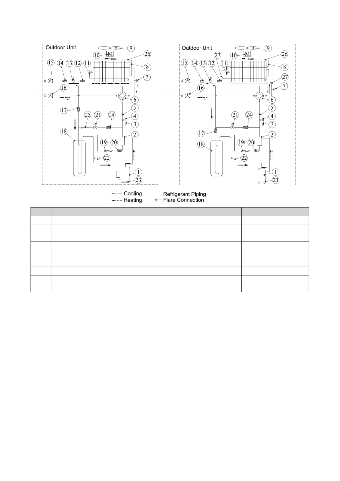
2.3 Refrigerant Cycle Diagram
Model:RAS-3.0~6.5HNBRKQ1 Model:RAS-7.0~12HNBRMQ1
No. Part Name No. Part Name No. Part Name
1 Compressor 10 Fan Motor 19 Oil Capillary Tube
2 Oil Separator 11 Distributor 20 Filter 4
3 High Pressure Switch 12 Filter 1 21 Solenoid Valve
4 High Pressure Sensor 13 Electronic Expansion Valve 22 Low Pressure Sensor
5 Check Valve 14 Filter 2 23 Crankcase Heater
6 4-Way Valve 15 Liquid Stop Valve 24 Filter 5
7 Check Joint 16 Gas Stop Valve 25 Bypass Capillary Tube
8 Gas Collector 17 Filter 3 26 Heat Exchanger
9 Propeller Fan 18 Accumulator 27 Y-shaped Joint
9
2.4 Model of Outdoor Unit
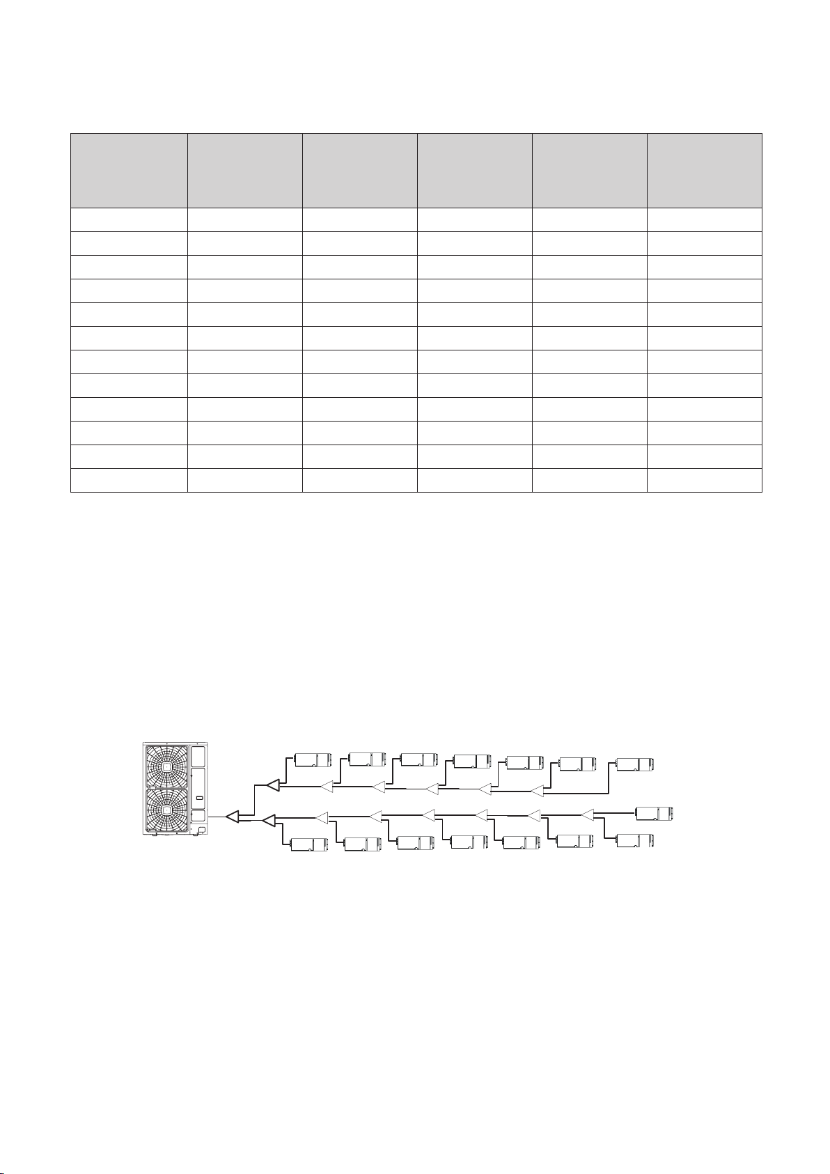
The number of indoor units that can be connected to an outdoor unit is dened in the following table :
Table 2.1 System Combination
Outdoor Unit Type
RAS-3.0HNBRKQ1 8.0 4.0 10.4 2~4 2.2
RAS-3.5HNBRKQ1 10.0 5.0 13.0 2~5 2.2
RAS-4.0HNBRKQ1 11.2 5.6 14.6 2~6 2.2
RAS-4.5HNBRKQ1 12.0 6.0 15.6 2~6 2.2
RAS-5.0HNBRKQ1 14.0 7.0 18.2 2~7 2.2
RAS-6.0HNBRKQ1 16.0 8.0 20.8 2~8 2.2
RAS-6.5HNBRKQ1 18.0 9.0 23.4 2~9 2.2
RAS-7.0HNBRMQ1 20.0 10.0 26.0 2~10 2.2
RAS-8.0HNBRMQ1 22.4 11.2 29.1
RAS-10HNBRMQ1 28.1 14.1 36.5
RAS-11HNBRMQ1 31.0 15.5 40.3
RAS-12HNBRMQ1 33.5 16.8 43.6
Rated
Capacity
(kW)
Min. Total
Capacity of the
indoor units can
be connected
(kW)
Max. Total
Capacity of the
indoor units can
be connected
(kW)
Numbers of the
indoor units can
be connected
(Q’ty)
2~10
△
2~10(13)
△
2~10(14)
△
2~10(15)
Min. Capacity
at Individual
Operation
(kW)
2.2
2.2
2.2
2.2
NOTES:
● The connectable indoor unit capacity ratio can be calculated as follows:
Connectable Indoor Unit Capacity Ratio = Total Indoor Unit Capacity / Total Outdoor Unit Capacity.
● For the same system, if the connectable indoor unit capacity ratio is over than 100%, and which all the indoor units operate
simultaneously, the capacity of every indoor unit should be less than its rated capacity.
● Combination capacity is 50-130%.
● △:When the number of indoor units which are connected to the model of RAS-10~12HNBRMQ1 outdoor unit is over than 10
units,the following restrictions are also required to meet.
(a) The piping system must be divided into two main pipes, the total capacity and the number of the units connected to each
main pipe should be as equal as possible.
(b) The maximum height difference between outdoor and indoor units is 30 meters and the maximum height difference
between indoor units is 10 meters, the longest piping length between the branch pipe to the connected indoor unit is 10m.
(c) The connectable indoor unit capacity ratio should not be more than 105%.
(d) Only 0.8~4.0HP of ducted indoor units can be selected.
No.1
No.2 No.3
No.4 No.5 No.6
No.7
No.15
No.8 No.9
No.10
No.11
No.12No.13
No.14
10
2.5 Transportation
More than 60°
Transport the product as near to the installation location before unwrapping the package.
NOTICE
● Do not put any material or stand on the product.
● Apply two lifting wires onto the outdoor unit, when lifting it by crane.
● The Method of Hanging
When hanging the unit, ensure a balance of the unit, ensure its safety and lift up smoothly.
(a) Do not unwrap the package until the hanging work is nished.
(b) The hanging work can be followed the next figure:
Wire Rope
0.7m~1.0m
Do not remove
corrugated paper
frame and plastic
band
NOTES:
● Make sure the unit is in horizontal while lifting.
● Do not hook with the plastic bands.
● If the unit is lifted after unwrapping the package, protect the unit with the corner paddings or cloth.
Attach corner padding or cloth here
● The weight of outdoor units is shown in the following table.
Model Net Weight (kg) Gross Weight (kg)
Apply rope
through the
square hole
RAS-3.0HNBRKQ1
RAS-3.5HNBRKQ1
RAS-4.0HNBRKQ1
RAS-4.5HNBRKQ1
RAS-5.0HNBRKQ1
RAS-6.0HNBRKQ1
RAS-6.5HNBRKQ1
RAS-7.0HNBRMQ1
RAS-8.0HNBRMQ1
75 85
114 124
118 128
154 168
11
Model Net Weight (kg) Gross Weight (kg)
RAS-10HNBRMQ1
WARNING
!
RAS-11HNBRMQ1
RAS-12HNBRMQ1
172 187
Do not place or leave any other objects (cables, tools) inside the outdoor unit or control board and verify
that nothing remains there prior to installation and test run. Ignoring the instructions can lead to damage and
re incidents.
2.6 Factory Supplied Accessories
The accessories are packed with the outdoor unit, please check that in the package.
Accessory Quantity Remarks
Wire Clamp (big) 1
Wire Clamp (small) 3
Magnetic Ring (big) 2
Magnetic Ring (small) 1
Only for RAS-
3.0~6.5HNBRKQ1
Washer 4
Wire Clamp (big) 2
Pipe Adapter 1 1
Pipe Adapter 2 1
NOTE:
If any of these accessories are not packed in the unit, please contact your distributor.
Only for RAS-
7.0~12HNBRMQ1
3. Outdoor Unit Installation
3.1 Installation Location and Precautions
● When installing the unit into:
● A wall: Make sure the wall is strong enough to hold the weight of the unit. It may be necessary to
construct a strong wood or metal frame to provide added support.
● A room: Properly insulate any refrigerant tubing run inside a room to prevent “sweating” that can
cause dripping and water damage to wall and oors.
● Damp or uneven areas: Use a raised concrete pad or concrete blocks to provide a solid and level
foundation for the unit to prevent water damage and abnormal vibration.
● An area with high winds: Securely anchor the outdoor unit down with bolts and a metal frame.
Provide a suitable wall for wind prevention (eld-supplied).
● A snowy area: Install the outdoor unit on a raised platform that is higher than drifting snow.
Provide snow roof for snow prevention (eld-supplied).
● Do not install the unit in the following places. Otherwise, it can result in an explosion, re, deformation,
corrosion, or product failure.
● Explosive or ammable atmosphere.
● Where a re, oil, steam, or powder can directly enter the unit, such as in close proximity or directly above
a kitchen stove.
● Where oil (including machinery oil) may be present.
● Where corrosive gases such as chlorine, bromine, or sulphide can accumulate, such as near a hot tub or
hot spring.
● Where dense, salt-laden airow is heavy, such as in coastal regions.
12
 Loading...