

Page 1
NO. 0019E
SPECIFICATIONS AND PARTS ARE SUBJECT TO CHANGE FOR IMPROVEMENT
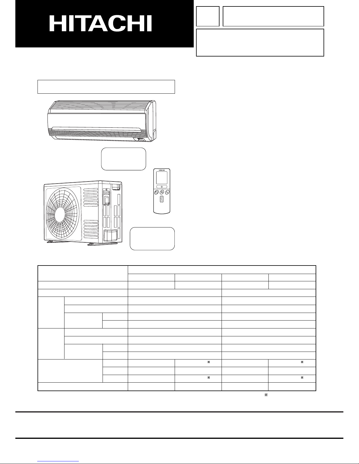
ROOM AIR CONDITIONER
INDOOR UNIT + OUTDOOR UNIT
DECEMBER 2006 Hitachi Household Appliances(Wuhu) Co.,Ltd.
SERVICE MANUAL
AW
REFER TO THE FOUNDATION MANUAL
TECHNICAL INFORMATION
FOR SERVICE PERSONNEL ONLY
(W)
(A)
(kW)
(B.T.U./h)
(W)
(A)
(kW)
(B.T.U./h)
W
H
D
(kg)
RAS-18YH6 RAC-18YH6
DC INVERTER (WALL TYPE)
TYPE
MODEL
POWER SOURCE
TOTAL INPUT
TOTAL AMPERES
CAPACITY
TOTAL INPUT
TOTAL AMPERES
CAPACITY
DIMENSIONS
(mm)
NET WEIGHT
SPECIFICATIONS
780
280
210
9.5
RAS-18YH6
RAS-25YH6
CONTENTS
SPECIFICATIONS ------------------------------------------------------------------- 4
HOW TO USE ----------------------------------------------------------------------- 5
CONSTRUCTION AND DIMENSIONAL DIAGRAM --------------------- 15
MAIN PARTS COMPONENT --------------------------------------------------- 17
WIRING DIAGRAM ---------------------------------------------------------------- 19
CIRCUIT DIAGRAM --------------------------------------------------------------- 20
RAS-18YH6/RAC-18YH6
RAS-25YH6/RAC-25YH6
RAC-18YH6
RAC-25YH6
COOLING
HEATING
INDOOR UNIT
OUTDOOR UNIT
INDOOR UNIT
OUTDOOR UNIT
1 PHASE, 50 Hz, 220-230V
550 (155 ~ 1,010)
2.95-2.81
2.00 (0.90 ~ 2.50)
6,820 (3,070 ~ 8,530)
580 (115 ~ 970)
2.93-2.81
2.50 (0.90 ~ 3.20)
8,530 (3,070 ~ 10,920)
505
27
780
280
210
9.5
505
27
1 PHASE, 50 Hz, 220-230V
700 (155 ~ 1,290)
3.75-3.59
2.50 (0.90 ~ 3.10)
8,530 (3,070 ~ 10,580)
880 (115 ~ 1,250)
4.45-4.26
3.40 (0.90 ~ 4.40)
11,600 (3,070 ~ 15,010)
After installation
RAS-25YH6 RAC-25YH6
BLOCK DIAGRAM ----------------------------------------------------------------- 22
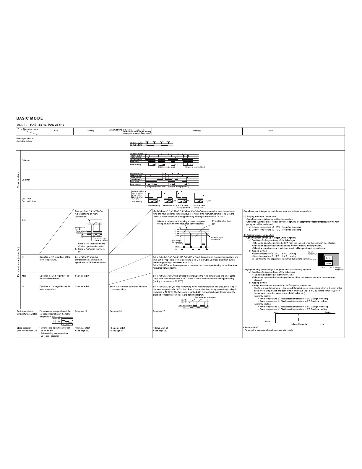
BASIC MODE ----------------------------------------------------------------------- 23
REFRIGERATING CYCLE DIAGRAM --------------------------------------- 29
DESCRIPTION OF MAIN CIRCUIT OPERATION ----------------------- 30
SERVICE CALL Q & A ---------------------------------------------------------- 60
TROUBLE SHOOTING ----------------------------------------------------------- 63
PROCEDURE FOR DISASSEMBLY AND REASSEMBLY ------------ 87
PARTS LIST AND DIAGRAM -------------------------------------------------- 89
700 (+68) 700 (+68)
258 (+48) 258 (+48)
Page 2
SAFETY DURING REPAIR WORK
First, I must disconnect
the power cord plug
from the power outlet.
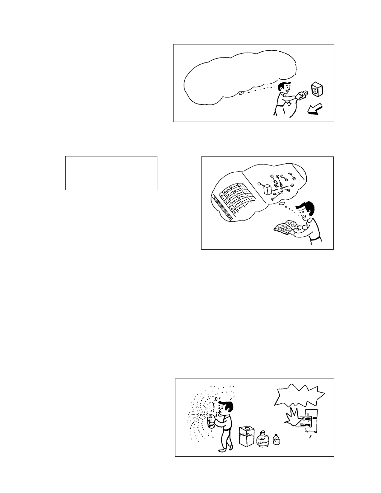
1. In order to disassemble and repair the unit
in question, be sure to disconnect the power
cord plug from the power outlet before
starting the work.
2. If it is necessary to replace any parts, they should be replaced with respective genuine parts for the unit, and
the replacement must be effected in correct manner according to the instructions in the Service Manual of the
unit.
If the contacts of electrical
parts are defective, replace the
electrical parts without trying to
repair them.
3. After completion of repairs, the initial state should
be restored.
4. Lead wires should be connected and laid as in the
initial state.
5. Modification of the unit by user himself should
absolutely be prohibited.
6. Tools and measuring instruments for use in repairs or inspection should be accurately calibrated in advance.
7. In installing the unit having been repaired, be careful to prevent the occurence of any accident such as
electrical shock, leak of current, or bodily injury due to the drop of any part.
8. To check the insulation of the unit, measure the insulation resistance between the power cord plug and grounding
terminal of the unit. The insulation resistance should be 1MΩ or more as measured by a 500V DC megger.
9. The initial location of installation such as window, floor or the other should be checked for being and safe
enough to support the repaired unit again.
If it is found not so strong and safe, the unit should be installed at the initial location reinforced or at a new
location.
10. Any inflammable thing should never be placed about the location of installation.
11. Check the grounding to see whether it is
proper or not, and if it is found improper,
connect the grounding terminal to the earth.
DANGER
Page 3
– 1 –
WORKING STANDARDS FOR PREVENTING BREAKAGE OF SEMICONDUCTORS
1. Scope
The standards provide for items to be generally observed in carrying and handling semiconductors in relative
manufacturers during maintenance and handling thereof. (They apply the same to handling of abnormal
goods such as rejected goods being returned).
2. Object parts
(1) Micro computer
(2) Integrated circuits (IC)
(3) Field-effect transistors (FET)
(4) P.C. boards or the like on which the parts mentioned in (1) and (2) of this paragraph are equipped.
3. Items to be observed in handling
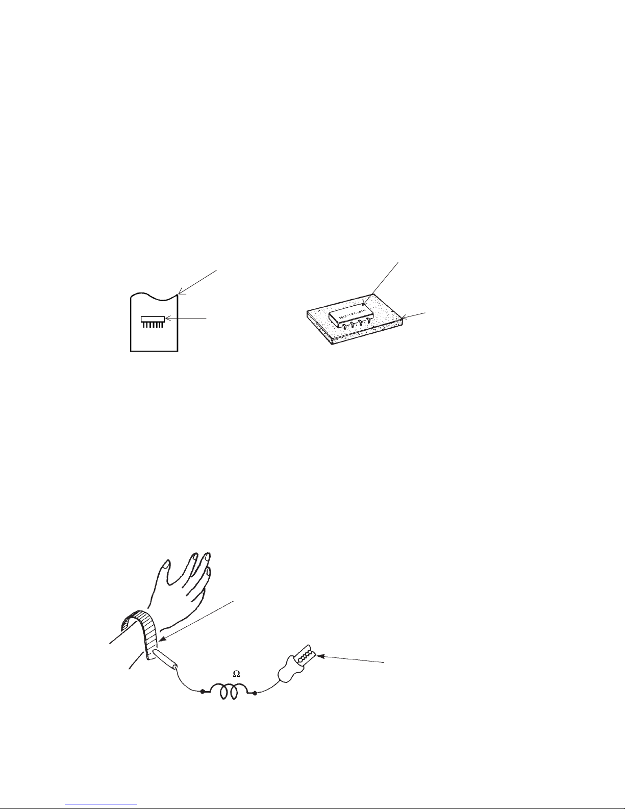
(1) Use a conductive container for carrying and storing of parts. (Even rejected goods should be handled in
the same way).
Fig. 1 Conductive Container
IC
A conductive polyvinyl bag
IC
Conductive sponge
(2) When any part is handled uncovered (in counting, packing and the like), the handling person must always
use himself as a body earth. (Make yourself a body earth by passing one M ohm earth resistance through
a ring or bracelet).
(3) Be careful not to touch the parts with your clothing when you hold a part even if a body earth is being
taken.
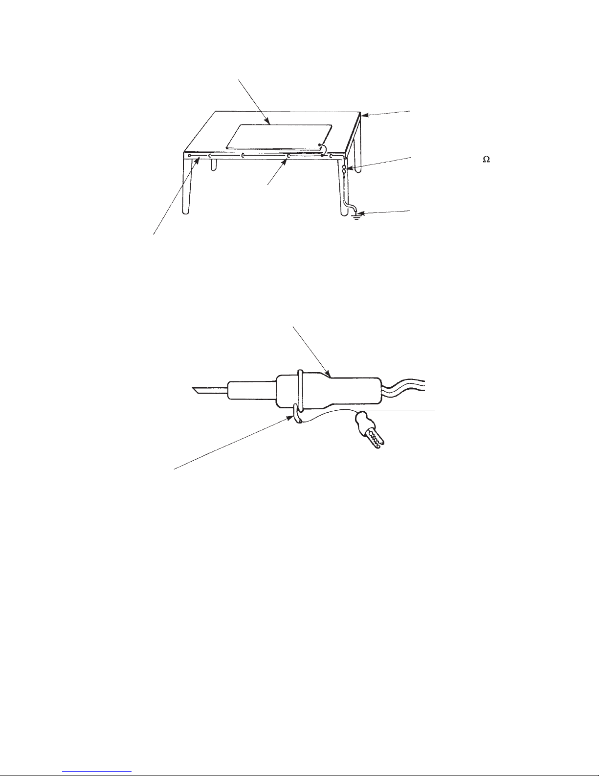
(4) Be sure to place a part on a metal plate with grounding.
(5) Be careful not to fail to turn off power when you repair the printed circuit board. At the same time, try to
repair the printed circuit board on a grounded metal plate.
1M
Fig. 2 Body Earth
Body earth
(Elimik conductive band)
Clip for connection with a
grounding wire
Page 4
– 2 –
(6)Use a three wire type soldering iron including a grounding wire.
Use a high insulation mode (100V, 10M or higher) when ordinary iron is to be used.
(7) In checking circuits for maintenance, inspection or some others, be careful not to have the test probes of
the measuring instrument shortcircuit a load circuit or the like.
Bare copper wire (for body earth)
Working
table
Resistor of 1 M
(1/2W)
Earth wire
Fig. 3 Grounding of the working table
Metal plate (of aluminium, stainless steel, etc.)
Staple
Screw stop at the screwed
part using a rag plate
Soldering iron
Grounding
wire
Fig. 4 Grounding a soldering iron
Page 5

– 3 –
1. In quiet operation or stopping the running, slight flowing noise of refrigerant in the refrigerating cycle is
heard occasionally, but this noise is not abnormal for the operation.
2. When it thunders near by, it is recommend to stop the operation and to disconnect the power cord plug from
the power outlet for safety.
3. The room air conditioner does not start automatically after recovery of the electric power failure for prevent-
ing fuse blowing. Re-press START/STOP button after 3 minutes from when unit stopped.
4. If the room air conditioner is stopped by adjusting thermostat, or missoperation, and re-start in a moment,
there is occasion that the cooling and heating operation does not start for 3 minutes, it is not abnormal and
this is the result of the operation of IC delay circuit. This IC delay circuit ensures that there is no danger of
blowing fuse or damaging parts even if operation is restarted accidentally.
5. This room air conditioner should not be used at the cooling operation when the outside temperature is
below -10°C (14°F).
6. This room air conditioner (the reverse cycle) should not be used when the outside temperature is below
–15°C (5°F).
If the reverse cycle is used under this condition, the outside heat exchanger is frosted and efficiency falls.
7. When the outside heat exchanger is frosted, the frost is melted by operating the hot gas system, it is not
trouble that at this time fan stops and the vapour may rise from the outside heat exchanger.
!
CAUTION
Page 6

– 4 –
SPECIFICATIONS
MODEL
FAN MOTOR
FAN MOTOR CAPACITOR
FAN MOTOR PROTECTOR
COMPRESSOR
COMPRESSOR MOTOR CAPACITOR
OVERLOAD PROTECTOR
OVERHEAT PROTECTOR
FUSE (for MICROPROCESSOR)
POWER RELAY
POWER SWITCH
TEMPORARY SWITCH
SERVICE SWITCH
TRANSFORMER
VARISTOR
NOISE SUPPRESSOR
THERMOSTAT
REMOTE CONTROL SWITCH (LIQUID CRYSTAL)
40 W
NO
NO
NO
ASC092CD
YES
YES
3.0A
G4A
NO
NO
YES
NO
450NR
YES
YES(IC)
NO
WITHOUT REFRIGERANT BECAUSE
COUPLING IS FLARE TYPE.
UNIT
PIPES (MAX. 20m)
REFRIGERANT CHARGING
VOLUME
(Refrigerant 410A)
RAC-18YH6
RAC-25YH6
820g
RAS-18YH6
RAS-25YH6
PWM DC35V
NO
NO
–
NO
NO
NO
NO
NO
YES
NO
NO
NO
NO
YES(IC)
YES
----------
YES
Page 7
– 2 –
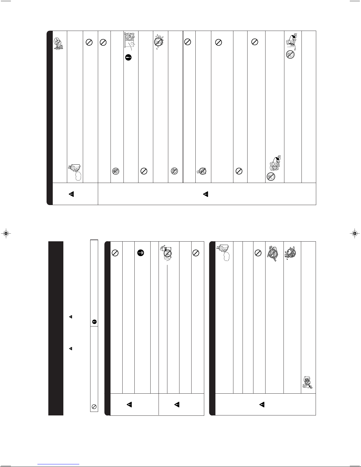
SAFETY PRECAUTION
• Please read the “Safety Precaution” carefully before operating the unit to ensure correct usage of the unit.
• Pay special attention to signs of “
Warning” and “ Caution”. The “Warning” section contains
matters which, if not observed strictly, may cause death or serious injury. The “Caution” section
contains matters which may result in serious consequences if not observed properly. Please observe
all instructions strictly to ensure safety.
• The signs indicate the following meanings. (The following are examples of signs.)
• Please keep this manual after reading.
This sign in the figure indicates prohibition. Indicates the instructions that must be followed.
WARNING
CAUTION
• Do not reconstruct the unit.
Water leakage, fault, short circuit or fire may occur if you reconstruct the unit by
yourself.
• Please ask your sales agent or qualified technician for the installation of your
unit.
Water leakage, short circuit or fire may occur if you install the unit by yourself.
• Please use earth line.
Do not place the earth line near water or gas pipes, lightning-conductor, or the
earth line of telephone. Improper installation of earth line may cause electric
shock.
• Be sure to use the specified piping set for R410A. Otherwise, this may result in
broken copper pipes or faults.
• A circuit breaker should be installed depending on the mounting site of the unit.
Without a circuit breaker, the danger of electric shock exists.
• Do not install the unit near a location where there is flammable gas.
The outdoor unit may catch fire if flammable gas leaks around it. Piping shall be
suitable supported with a maximum spacing of 1m between the supports.
• Please ensure smooth flow of water when installing the drain hose. If any failure
is found in the drain path, water drops from the indoor and outdoor units, causing
wet household effects.
• Make sure that a single phase 230V power source is used.
The use of other power sources may cause electrical components to overheat
and lead to fire.
PROHIBITION
CONNECT EARTH LINE
PROHIBITION
PROHIBITION
• Should abnormal situation arise (like burning smell), please stop operating the
unit and remove plug from the socket or turn off the circuit breaker. Contact your
agent. Fault, short circuit or fire may occur if you continue to operate the unit
under abnormal situation.
• Please contact your agent for maintenance.
Improper self maintenance may cause electric shock and fire.
• Please contact your agent if you need to remove and reinstall the unit.
Electric shock or fire may occur if you remove and reinstall the unit yourself improperly.
WARNING
PRECAUTIONS DURING INSTALLATION
PRECAUTIONS DURING SHIFTING OR MAINTENANCE
“OFF”
PROHIBITION
• Avoid an extended period of direct air flow for your health.
• Do not connect the power calbe with an extension cable or do not plug too many
leads of the other electric appliance into the socket where this cable is plugged.
In addition, wire the cable with some allowances to prevent the cable from stretching.
Not doing so will cause an electrical shock, heat generation or fire.
PROHIBITION
• Do not put objects like thin rods into the panel of blower and suction side
because the high-speed fan inside may cause danger.
• Do not bundle the power cable, pull it, put something on it, heat it, process it, or
put it between things. Breakage of the power cable may result.
Use of a damaged cable may cause an electrical shock or a fire.
PROHIBITION
PROHIBITION
HOW TO USE
– 3 –
WARNING
PRECAUTIONS DURING OPERATION
• Do not use any conductor as fuse wire, this could cause fatal accident.
PROHIBITION
• During thunder storm, disconnect the plug top or turn off the circuit breaker.
• Spray cans and other combustibles should not be located within a meter of the air
outlets of both indoor and outdoor units.
As a spray can’s internal pressure can be increased by hot air, a rupture may result.
“OFF”
CAUTION
PROHIBITION
• The product shall be operated under the manufacturer specification and not for
any other intended use.
PROHIBITION
DON’T WET
• Do not attempt to operate the unit with wet hands, this could cause fatal accident.
STRICTLY OBSERVE
PRECAUTIONS
PROHIBITION
PROHIBITION
PROHIBITION
PROHIBITION
PROHIBITION
• When operating the unit with burning equipments, regularly ventilate
the room to avoid oxygen insufficiency.
• Do not direct the cool air coming out from the air-conditioner panel to
face household heating apparatus as this may affect the working of
apparatus such as the electric kettle, oven etc.
• Do not wash the unit with water or place a water container such as a
vase on the indoor unit.
Electrical leakage could be present and cause electric shock.
• Please ensure that outdoor mounting frame is always stable, firm and
without defect. If not, the outdoor unit may collapse and cause danger.
• Do not place plants or animals directly under the air flow as it is bad for the plants or
animals.
• Do not climb on the outdoor unit or put objects on it.
PROHIBITION
PROHIBITION
PROHIBITION
DON’T TOUCH
DON’T TOUCH
• When operating the unit with the door and windows opened, (the room humidity
is always above 80%) and with the air deflector facing down or moving automati-
cally for a long period of time, water will condense on the air deflector and drips
down occasionally. This will wet your furniture. Therefore, do not operate under
such condition for a long time.
• If the amount of heat in the room is above the cooling or heating capability of the
unit (for example: more people entering the room, using heating equipments and
etc.), the preset room temperature cannot be achieved.
• This appliance especially indoor unit cleaning must be performed by authorized
personnel only. Consult your sales agent.
Using a commercially available detergent or similar can damage the plastic parts
or clog the drain pipe, causing water to drip with potential electric shock hazard.
• Do not touch the air outlet, bottom surface and aluminum fin of the outdoor
unit.
You may get hurt.
• Do not touch the refrigerant pipe and connecting valve.
Burns may result.
• This appliance is not intended for use by young children or infirm persons unless they have been
adequately supervised by a responsible person to ensure that they can use this appliance safely.
• Young children should be supervised to ensure that they do not play with the appliance.
– 5 –
Page 8
– 4 –
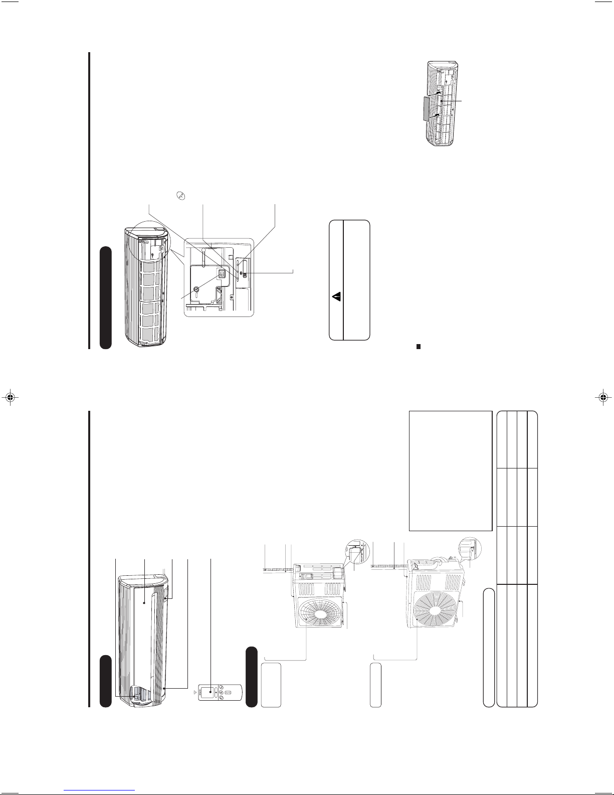
NAMES AND FUNCTIONS OF EACH PART
INDOOR UNIT
Air filter
To prevent dust from coming into the indoor unit.
(Refer page 16)
Front panel
Indoor unit indicators
Light indicator showing the operating condition.
(Refer page 5)
Horizontal deflector Vertical deflector
(Air Outlet)
(Refer page 15)
Remote controller
Send out operation signal to the indoor unit. So as
to operate the whole unit.
(Refer page 6)
MODEL NAME AND DIMENSIONS
About the outdoor unit:
• When “Stop” is selected during operation
of the indoor unit, the fan of the outdoor
unit continues turning for 10 to 60
seconds to cool the electric parts down.
• In heating operation, condensate or
water due to defrosting will flow.
Do not cover the drain port of the outdoor
unit because such water may freeze in
the chilly area.
• When the outdoor unit is hung on the
ceiling, install the bush and drain pipe
on the drain port and drain water.
MODEL WIDTH (mm) HEIGHT (mm) DEPTH (mm)
RAS-18YH6, RAS-25YH6, RAS-35YH6 780 280 210
RAC-18YH6, RAC-25YH6 700 505 258
RAC-35YH6 750 548 288
Air outlet
When “ heating” operation is
performed, cool air blows and
when “cooling” or “dehumidifying”
operation is performed, warm air
blows.
Drain hose
Drains the dehumidified water from the indoor unit to the
outdoor during “cooling” or “dehumidifying” operation.
Piping and Wiring
Air inlets (Rear and left sides)
Drain port
(Bottom)
Earth terminal
(Lower section of the side)
RAC-35YH6
RAC-18YH6
RAC-25YH6
OUTDOOR UNIT
– 5 –
NAMES AND FUNCTIONS OF EACH PART
INDOOR UNIT INDICATIONS
TIMER LAMP (Orange)
This lamp lights when the timer is working.
FILTER LAMP (Green)
When the device is operated for a total of about 200
hours, the FILTER lamp lights indicates that it is time
to clean the filter.The lamp goes out when the
“
(AUTO SWING)” button is pressed while the
operation is stopped.
OPERATION LAMP (Yellow)
This lamp lights during operation.
The OPERATION LAMP flashes in the following
cases during heating.
(1) During preheating
For about 2-3 minutes after starting up.
(2) During defrosting
Defrosting will be performed about once an hour
when frost forms on the heat exchanger of the
outdoor unit, for 5-10 minutes each time.
TEMPORARY SWITCH
●
Use this switch to start and stop when the remote controller does not work.
●
This temporary operation will be at the most recent setting made. (The unit
will immediately go into automatic operation once power is switched on.)
CAUTION
Turn off the circuit breaker or pull out
the power plug if the unit is not be
operated for a long period.
✩ If the power stays on and the unit is not operated, power is slightly consumed in the control circuit.
The power is saved by turning off the power switch (or the circuit breaker when the power is supplied
from the outdoor unit).
Attaching the air cleansing and deodorizing filters (Accessories) to the filter frame.
• Attach the air cleansing and deodorizing filters to the frame by
gently compress its both sides and release after insertion into
filter frame.
• The cooling capacity is slightly weakened and the cooling speed
becomes slower when the air cleansing and deodorizing filters
are used.
• Air cleansing and deodorizing filters are washable and reusable up to 20 times by using vacuum
cleaner or water rinse under running tap water. When you want to renew it, please ask your sales
agent.
Frame
POWER SWITCH
– 6 –
Page 9
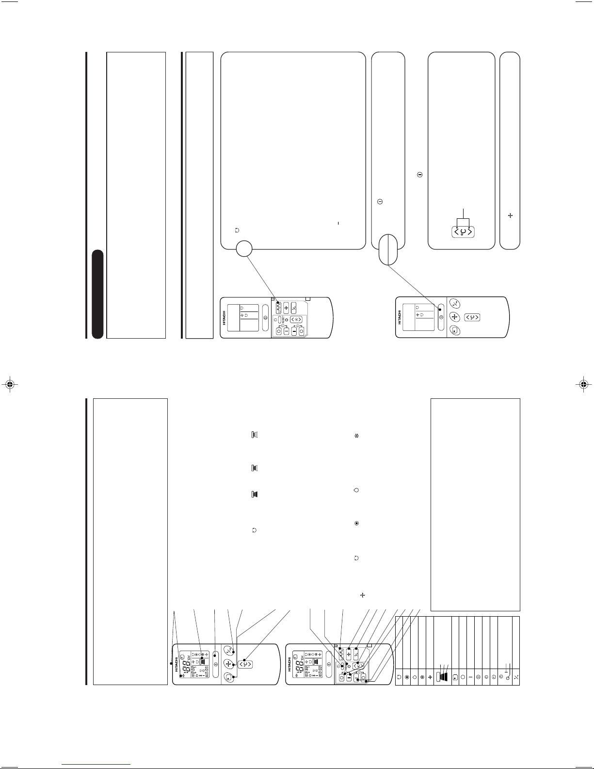
– 6 – – 7 –
● Signal emitting window/transmission sign
Point this window toward the indoor unit when controlling it.
The transmission sign blinks when a signal is sent.
● Display
This indicates the room temperature selected, current time, timer status,
function and intensity of circulation selected.
● START/STOP button
Press this button to start operation. Press it again to stop operation.
● AUTO SWING button
Controls the angle of the horizontal air deflector.
● FAN SPEED selector
This determines the fan speed. Every time you press this button, the intensity of
circulation will change from (AUTO) to (HI) to (MED) to (LOW).
(This button allows selecting the optimal or preferred fan speed for each
operation mode.)
● SLEEP button
Use this button to set the sleep timer.
● TEMPERATURE buttons
Use these buttons to raise or lower the temperature setting. (Keep pressed, and
the value will change more quickly.)
● TIME button
Use this button to set and check the time and date.
● RESET button
Press this button after the batteries are replaced or when some irregular
operation is found.
● FUNCTION selector
Use this button to select the operating mode. Every time you press it, the mode
will change from (AUTO) to (HEAT) to (DEHUMIDIFY) to (COOL) and
to (FAN) cyclically.
● FAN SPEED selector
● AUTO SWING button
● TIMER control
Use these buttons to set the timer.
● OFF-TIMER button Select the turn OFF time.
● ON-TIMER button Select the turn ON time.
● RESERVE button Time setting reservation.
● CANCEL button Cancel time reservation.
VARIOUS FUNCTIONS
■ Auto Restart Control
• If there is a power failure, operation will be automatically restarted when the power is resumed with
previous operation mode and airflow direction.
(As the operation is not stopped by remote controller.)
• If you intend not to continue the operation when the power is resumed, switch off the power supply.
When you switch on the circuit breaker, the operation will be automatically restarted with previous
operation mode and airflow direction.
Note: 1. If you do not require Auto Restart Control, please consult your sales agent.
2. Auto Restart Control is not available when Timer or Sleep Timer mode is set.
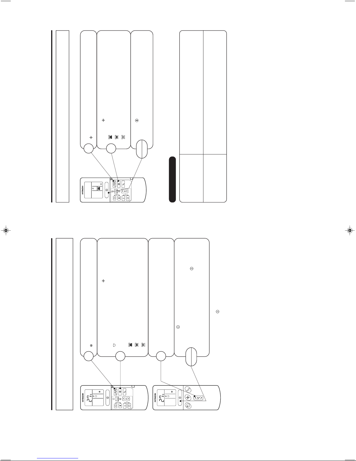
AUTOMATIC OPERATION
The device will automatically determine the mode of operation, HEAT or COOL depending on the
initial room temperature. The selected mode of operation will change when the room temperature
varies.
Press the FUNCTION selector so that the display indicates the
(AUTO) mode of operation.
• When AUTO has been selected, the device will automatically
determine the mode of operation, HEAT or COOL depending
on the current room temperature.
• When AUTO is first selected, the device will determine the
current room temperature and select the proper operation
mode accordingly.
• When the air conditioner has adjusted the room's temperature
to the near preset temperature, it will begin to monitor
operation. If the room temperature subsequently changes,
the air conditioner will once again select the appropriate
operation (heating or cooling) to adjust the temperature to
the preset temperature. The monitoring operation range is
+
3°C relative to the preset temperature.
• If the mode automatically selected by the unit is not
satisfactory, manually change the mode setting (heat,
dehumidify, cool or fan).
1
NAMES AND FUNCTIONS OF EACH PART
REMOTE CONTROLLER
• This controls the operation of the indoor unit.
The range of control is about 7 meters. If indoor lighting is controlled electronically, the range of
control may be shorter, in some cases, the control signal may not be received.
This unit can be fixed on a wall using the fixture provided. Before fixing it, make sure the indoor unit
can be controlled from the remote controller.
• Handle the remote controller with care.
Dropping it or getting it wet may compromise its signal transmission capability.
• After new batteries are inserted into the remote controller, the unit will initially require approximately
10 seconds to respond to commands and operate.
Precautions for Use
• Do not put the remote controller in the following places.
• In direct sunlight
• In the vicinity of a heater.
• Handle the remote controller carefully. Do not drop it on the floor, and
protect it from water.
• Once the outdoor unit stops, it will not restart for about 3 minutes (unless
you turn the power switch off and on or unplug the power cord and plug
it in again).
This is to protect the device and does not indicate a failure.
• If you press the FUNCTION selector button during operation, the device
may stop for about 3 minutes for protection.
AUTO
HEAT
DEHUMIDIFY
COOL
FAN
FAN SPEED
LOW
MED
HI
SLEEPING
STOP (CANCEL)
START (RESERVE)
START/STOP
TIME
TIMER SET
TIMER SELECTOR
ON TIMER
OFF TIMER
AUTO SWING
Press the (START/STOP) button.
Operation starts with a beep.
Press the button again to stop operation.
Press the (FAN SPEED) button, AUTO and LOW is available.
■ As the settings are stored in memory in the remote controller, you
only have to press the
(START/STOP) button next time.
You can raise or lower the temperature setting as necessary by
maximum of 3°C.
Press the temperature button and the temperature
setting will change by 1°C each time.
• The preset temperature and the actual room temperature may
vary somewhat depending on conditions.
START
STOP
– 7 –
Page 10

– 8 –
Press the (START/STOP) button. Heating operation starts
with a beep. Press the button again to stop operation.
START
STOP
HEATING OPERATION
• Use the device for heating when the outdoor temperature is under 21°C.
When it is too warm (over 21°C), the heating function may not work in order to protect the device.
• In order to keep reliability of the device, please use this device above -15°C of the outdoor
temperature.
Press the FUNCTION selector so that the display indicates
(HEAT).
1
Set the desired FAN SPEED with the (FAN SPEED) button
(the display indicates the setting).
(AUTO) : The fan speed changes automatically according
to the temperature of the air which blows out.
(HI) : Economical as the room will become warm
quickly.
But you may feel a chill at the beginning.
(MED) : Quiet.
(LOW) : More quiet.
2
Set the desired room temperature with the TEMPERATURE
buttons (the display indicates the setting).
The temperature setting and the actual room temperature may
vary somewhat depending on conditions.
3
■ As the settings are stored in memory in the remote controller, you
only have to press the
(START/STOP) button next time.
■ Defrosting
Defrosting will be performed about once an hour when frost forms on the heat exchange of the outdoor unit,
for 5~10 minutes each time.
During defrosting operation, the operation lamp blinks in cycle of 3 seconds on and 0.5 second off.
The maximum time for defrosting is 20 minutes.
(If the piping length used is longer than usual, frost will likely to form.)
– 9 –
DEHUMIDIFYING OPERATION
Use the device for dehumidifying when the room temperature is over 16°C.
When it is under 15°C, the dehumidifying function will not work.
Press the (START/STOP) button.
START
STOP
Press the FUNCTION selector so that the display indicates
(DEHUMIDIFY).
The FAN SPEED is set at LOW automatically.
The FAN SPEED button does not work.
1
■ When you want to change the operation mode, please use the
FUNCTION selector.
■ Set the desired temperature is available.
■ You also can use the FUNCTION selector to select this operation.
■ Dehumidifying Function
• Dehumidifying takes place with a target temperature which is slightly lower than the room
temperature setting. (However, target temperature is 16°C for a temperature setting of 16°C.)
If the room temperature becomes lower than the target value, operation stops. If the room
temperature becomes higher than the target value, operation restarts.
• The preset room temperature may not be reached depending on the number of people present in
the room conditions.
– 8 –
Page 11
– 10 –
Press the (START/STOP) button. Cooling operation starts
with a beep. Press the button again to stop operation. The cooling
function does not start if the temperature setting is higher than
the current room temperature (even though the (OPERATION)
lamp lights).
The cooling function will start as soon as you set the temperature
below the current room temperature.
START
STOP
COOLING OPERATION
Use the device for cooling when the outdoor temperature is -10 to 42°C.
If humidity is very high (over 80%) indoors, some dew may form on the air outlet grille of the indoor
unit.
Press the FUNCTION selector so that the display indicates
(COOL).
1
Set the desired FAN SPEED with the (FAN SPEED) button
(the display indicates the setting).
(AUTO) : The FAN SPEED is HI at first and varies to MED
automatically when the preset temperature has
been reached.
(HI) : Economical as the room will become cool quickly.
(MED) : Quiet.
(LOW) : More quiet.
2
Set the desired room temperature with the TEMPERATURE
buttons (the display indicates the setting).
The temperature setting and the actual room temperature may
vary somewhat depending on conditions.
3
■ As the settings are stored in memory in the remote controller, you
only have to press the
(START/STOP) button next time.
– 11 –
Press the (START/STOP) button. Fan operation star ts with a
beep.
Press the button again to stop operation.
START
STOP
FAN OPERATION
You can use the device simply as an air circulator. Use this function to dry the interior of the indoor unit
at the end of summer.
Press the FUNCTION selector so that the display indicates
(FAN).
1
Press the (FAN SPEED) button.
(HI) : The strongest air blow.
(MED) : Quiet.
(LOW) : More quiet.
2
FAN SPEED (AUTO)
… When the AUTO fan speed mode is set in the cooling/heating operation:
For the heating operation
• The fan speed will automatically change according to the temperature of
discharged air.
• As room temperature reaches the preset temperature, a very light breeze
will blow.
• Operation starts in the “HI” mode to reach the preset temperature.
• As room temperature approaches the preset temperature, fan speed auto-
matically switches to “LOW”.
For the cooling operation
– 9 –
Page 12
– 12 –
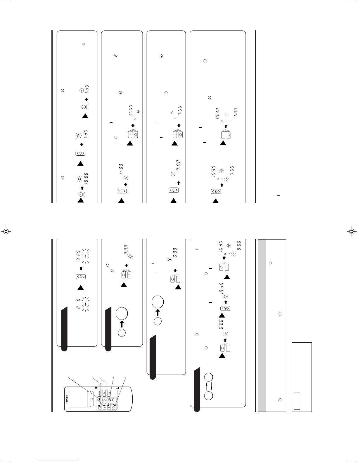
HOW TO SET THE TIMER
Time, Day, Month
TIME, DAY,
MONTH (current
time, day, month)
OFF TIMER
ON TIMER
RESERVE
CANCEL
OFF-Timer
ON-Timer
ON/OFF-Timer
1
Set the current month and day
with the TIMER control button.
DM
M D
After you change the
batteries;
Start
Stop
You can set the device to turn off at
the present time.
1
Press the (OFF-TIMER)
button. The (OFF) mar k blinks
on the display.
The device will turn on at the
designated times.
1
Press the (ON-TIMER)
button. The (ON) mark blinks on
the display.
AM
Start Stop
• The device will turn on (off) and
off (on) at the designated times.
• The switching occurs first at the
preset time that comes earlier.
• The arrow mark appear ing on the
display indicates the sequence of
switching operations.
1
Press the (OFF-
TIMER) button so that
the (OFF) mark
blinks.
2
Set the turn-off time
with the TIMER control
button.
Press the (RESERVE)
button.
PM
3
Press the (ON-
TIMER) button so that the
(OFF) mark lights and
the (ON) mark blinks.
PM
AM
How to Cancel Reservation
Point the signal window of the remote controller toward the indoor unit, and press the (CANCEL)
button.
The
(RESERVED) sign goes out with a beep and the (TIMER) lamp turns off on the indoor unit.
NOTE
You can set only one of the OFF-timer,
ON-timer and ON/OFF-timer.
Start
Stop
AM
PM
– 13 –
2
Set the
(TIME) button.
3
Set the current time with
the TIMER control button.
4
Press the (TIME)
button again. The time
indication starts lighting
instead of flashing.
• The time indication will
disappear automatically in 10
seconds.
• To check the current time
setting, press the (TIME)
button twice.
The setting of the current
time is now complete.
AM
PM
PM
PM
Example: The current time is 1:30p.m.
2
Set the turn-off time with
the TIMER control button.
PM
3
Point the signal window of the remote controller toward the indoor unit,
and press the (RESERVE) button.
The (OFF) mark starts lighting instead of flashing and the (RESERVED)
sign lights. A beep occurs and the (TIMER) lamp lights on the indoor unit.
PM
Example: The device will turn off at 11:00p.m.
The setting of turn-off time is now complete.
2
Set the turn-on time with
the TIMER control button.
AM
3
Point the signal window of the remote controller toward the indoor unit,
and press the (RESERVE) button.
The (ON) mark starts lighting instead of flashing and the (RESERVED)
sign lights. A beep occurs and the (TIMER) lamp lights on the indoor unit.
AM
Example:
The device will turn on early so that the preset
temperature be almost reached at 7:00 a.m.
The setting of the turn-on time is now complete.
4
Set the turn-on time with
the TIMER control button.
5
Point the signal window of the remote controller toward the indoor unit,
and press the (RESERVE) button.
The (ON) mark starts lighting instead of flashing and the (RESERVED)
sign lights. A beep occurs and the (TIMER) lamp lights on the indoor unit.
Example:
For heating, the device will turn off at 10:30 p.m.,
and then turn on early so that the preset
temperature be almost reached at 7:00 a.m.;
for cooling and dehumidifying, it will simply
turned on at 7:00 a.m. The settings of the turn
on/off times are now complete.
PM
AM
PM
AM
• The timer may be used in three ways: off-timer, on-timer and ON/OFF (OFF/ON)-timer. Set the
current time at first because it serves as a reference.
• As the time settings are stored in memory in the remote controller, you only have to press the
(RESERVE) button is order to use the same settings next time.
– 10 –
Page 13
– 14 –
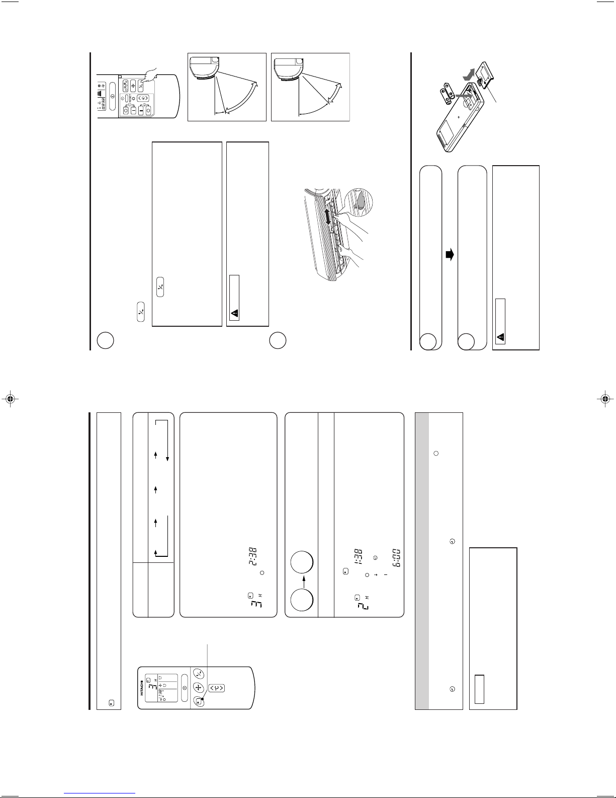
HOW TO SET THE SLEEP TIMER
Set the current time at first if it is not set before (see the pages for setting the current time). Press the
(SLEEP) button and the display changes as shown below.
●
SLEEP
Mode Indication
Sleep Timer
1 hour 2 hours 3 hours 7 hours
Sleep timer off
Sleep Timer: The device will continue working for the desired number of
hours and then turn off.
Point the signal window of the remote controller toward the indoor unit, and
press the SLEEP button.
The timer information will be displayed on the remote controller. The TIMER
lamp lights with a beep from the indoor unit. When the sleep timer has
been set, the display indicates the turn-off time.
AM
Example: If you set 3 hours sleep time at
11:38 p.m., the turn-off time is 2:38 a.m.
Sleep
timer
Start
The device will be turned off by the sleep timer
and turned on by on-timer.
1
Set the ON-timer.2 Press the (SLEEP) button and set the sleep timer.
AM
AM
For heating:
In this case, the device will turn off in
2 hours (at 1:38 a.m.) and turn on early
so that the preset temperature will be
almost reached at 6:00 next morning.
How to Cancel Reservation
Point the signal window of the remote controller toward the indoor unit, and press the (CANCEL)
button.
The
(RESERVED) sign goes out with a beep and the (TIMER) lamp turns off on the indoor unit.
NOTE
If you set the sleep timer when the off-time or on/off-
timer has been set earlier, the sleep timer becomes
effective instead of the off - or on/off-timer set earlier.
– 15 –
ADJUSTING THE AIR DEFLECTORS
1
Adjustment of the conditioned air in the upward and downward
directions.
The horizontal air deflector is automatically set to the proper angle
suitable for each operation. The deflector can be swung up and
down continuously and also set to the desired angle using the
“
(AUTO SWING)” button.
• In “Cooling” operation, do not keep the horizontal air
deflector swinging for a long time. Some dew may form on
the horizontal air deflector and dew may drop.
CAUTION
2
Adjustment of the conditioned air to the left and right.
Hold the vertical air deflector as shown in the figure and adjust
the conditioned air to the left and right.
HOW TO EXCHANGE THE BATTERIES IN THE REMOTE CONTROLLER
1
Remove the cover as shown in the figure and take out
the old batteries.2Install the new batteries.
The direction of the batteries should match the marks
in the case.
1. Do not use new and old batteries, or different kinds of
batteries together.
2. Take out the batteries when you do not use the remote
controller for 2 or 3 months.
CAUTION
Push and pull to the
direction of arrow.
Vertical
Vertical
about 15°
about 60°
about 45°
about 30°
When cooling,
dehumidifying
When heating
•
If the “ (AUTO SWING)” button is pressed once, the horizontal
air deflector swings up and down. If the button is pressed again, the
deflector stops in its current position. Several seconds (about 6
seconds) may be required before the deflector starts to move.
• Use the horizontal air deflector within the adjusting range
shown in the right.
• When the operation is stopped, the horizontal air deflector
moves and stops at the position where the air outlet closes.
Left side: Hold the third
blade from the left end
of the air deflector to
adjust the direction. The
pull for the blade is
marked.
Right side: Hold the third
blade from the right end
of the air deflector to
adjust the direction. The
pull for the blade is
marked.
– 11 –
Page 14
– 16 –
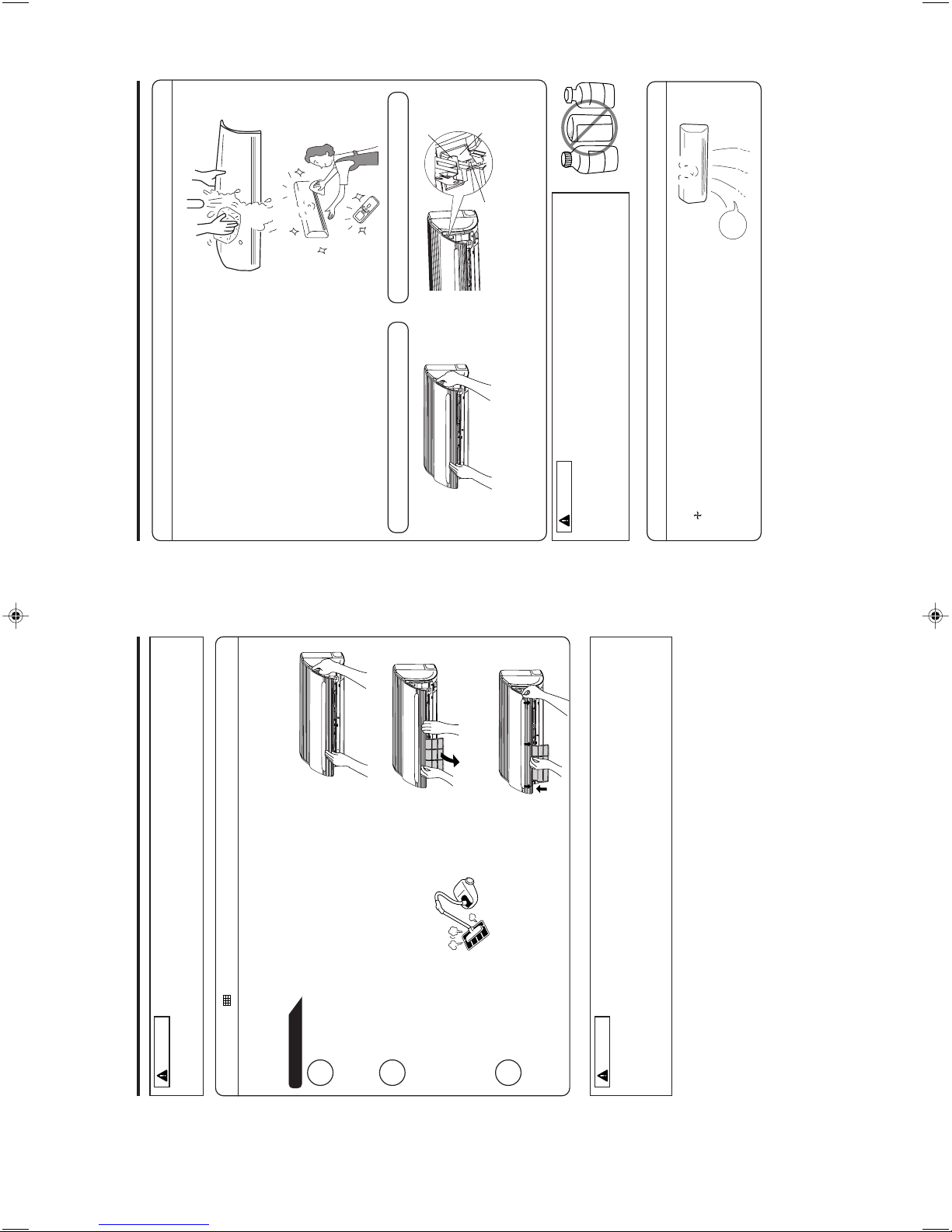
MAINTENANCE
Cleaning and maintenance must be carried out only by qualified service personal. Before cleaning,
stop operation and switch off the power supply.
CAUTION
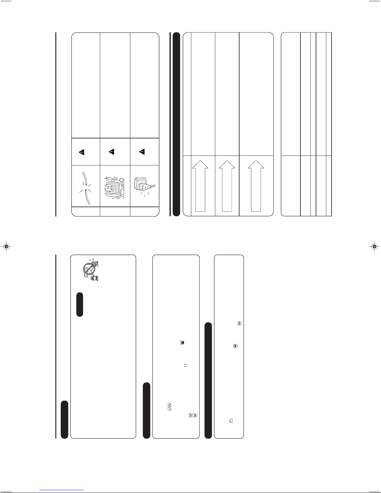
1. AIR FILTER
When the filter indicator lamp comes on, be sure to clean the filter. By doing so, the power rates are
saved. In case the air filter is full of dust, the air flow will decrease and the cooling capacity will be
reduced. Further, noise may occur. Be sure to clean the filter following the procedure below.
PROCEDURE
1
Open the front panel carefully and remove the filter.
2
Vacuum dust from the air filter using vacuum cleaner.
If there is too much dust, wash the filter with a detergent
and rinse it thoroughly. After that, dry it in the shade.
3
• Set the filter with “FRONT” mark facing front, and
slot them into the original state.
• After attaching the filters, push the front panel at
three arrow portions as shown in figure and close
it.
• Do not wash with hot water at more than 40°C. The filter may shrink.
• When washing it, shake off moisture completely and dry it in the shade; do not expose it directly
to the sun. The filter may shrink.
• Don't operate the unit without filter. Fault may occur if you continue.
CAUTION
– 17 –
2. CLEANING OF FRONT PANEL
• Remove the front panel and wash with clean water.
Wash it with a soft sponge.
After using neutral detergent, wash thoroughly with
clean water.
• When front panel is not removed, wipe it with a soft
dry cloth. Wipe the remote controller thoroughly with
a soft dry cloth.
• Wipe the water thoroughly.
If water remains at indicators or signal receiver of
indoor unit, it causes trouble.
Method of removing the front panel.
Be sure to hold the front panel with both hands to
detach and attach it.
CAUTION
Removing the Front Panel Attaching the Front Panel
• When the front panel is fully opened with both
hands, push the right arm to the inside to
release it, and while closing the front panel
slightly, put it out forward.
• Move the shafts of the left and right arms into
the steps in the unit and securely insert them
into the holes.
Shaft
Step
Hole
B
E
N
Z
I
N
E
T
H
I
N
N
E
R
A
CID
• Do not splash or direct water to the body of the unit when cleaning it as
this may cause short circuit.
• Never use hot water (above 40°C), benzine, gasoline, acid, thinner or a
brush, because they will damage the plastic surface and the coating.
3. MAINTENANCE AT BEGINNING OF LONG OFF PERIOD
• Run the unit by setting the operation mode to
(FAN) and the fan speed to HI for about half a day
on a fine day, and dry the whole of the unit.
• Switch off the power plug or turn off the circuit breaker.
Air
Blow
– 12 –
Page 15
– 18 –
INFORMATION
CAPABILITIES
Heating Capability
• This room air conditioner utilizes a heat pump system that absorbs
exterior heat and brings it into a room to be heated. As the ambient
temperature gets lower, heating capability will also lower. In such a
situation, the inverter work to increase compressor rpm to keep the
unit’s heating capability from decreasing. If the unit’s heating perfor-
mance is still unsatisfactory, other heating appliances should be used
to augment this unit’s performance.
• The air conditioner is designed to heat an entire room so that it may take some time before you feel warm.
Timer operation is recommended for effective preheating ahead of the desired time.
Cooling and Dehumidifying Capabilities
• If the heat present in a room exceeds the unit’s cooling capacity (for example, if there are many people in
the room or other heating appliances are used), the preset room temperature may not be reached.
CAUTION
Do not use a stove
or any other
hightemperature
devices in proximity
to the indoor unit.
• When fan speed, room temperature are set with the remote controller before starting manual operation and
the buttons are released, the indication of settings will go off in 10 seconds and only the operation mode
will be displayed.
• Pressing the button while the unit is in operation will let the protective circuit work so that the unit will
not operate for approximately 3 minutes.
• During heating operation, the indoor unit’s color indicator lamp may flash with no air emitted for a while.
• If you feel cold wind during heating operation with the (HI) fan speed or want to make the unit operation
quieter after the room is heated, use of (AUTO) setting is recommended.
• With the (LOW) setting, the unit’s cooling capability will lower slightly.
• With the (LOW) setting, the unit’s heating capacity will vary with the operating conditions.
VARIOUS FUNCTIONS
• When the timer has been programmed, the unit will not operate even if the set time is reached unless the
unit receives a signal from the remote controller. Confirm that timer programming is complete (beep) and
the TIMER lamp of the indoor unit lights.
• If the (SLEEP) button is pressed while the ON/OFF timer is programmed, the sleep timer takes priority.
• During sleep timer operation, the fan speed sets to (LOW) regardless of the preset speed. The remote
controller display indication will remain unchanged even with the (LOW) setting.
TIMER PROGRAMMING/SLEEP TIMER OPERATION
PROHIBITION
– 19 –
REGULAR INSPECTION
PLEASE CHECK THE FOLLOWING POINTS EVERY EITHER HALF YEARLY OR YEARLY. CONTACT
YOUR SALES AGENT SHOULD YOU NEED ANY HELP.
1
2
3
WARNING
WARNING
Check to see if the unit’s earth line has been con-
nected correctly.
If the earth line is disconnected or faulty, unit failure or
electric shock hazard may result.
Check to see if the mounting frame has rusted ex-
cessively or if the outdoor unit has tilted or become
unstable.
It could collapse or fall, causing injury.
AFTER SALES SERVICE AND WARRANTY
WHEN ASKING FOR SERVICE, CHECK THE FOLLOWING POINTS.
CONDITION CHECK THE FOLLOWING POINTS
• Do the batteries need replacement?
• Is the polarity of the inserted batteries correct?
• Is the fuse all right?
• Is the voltage extremely high or low?
• Is the circuit breaker “ON”?
• Is the power plug inserted?
• Do you have any power cut?
• Is the air filter blocked with dust?
• Is the set temperature suitable?
• Have horizontal air deflectors been adjusted to their correct
positions according to the operation mode selected?
• Are the air inlets or air outlets of indoor and outdoor units
blocked?
• Is the fan speed “LOW”?
When it does not operate.
When it does not cool well.
When it does not heat well.
If the remote controller is not
transmitting a signal.
(Remote controller display is
dim or blank.)
■ The following phenomena do not indicate unit failure.
<Operation start>
The unit is preparing to blow warm air. Please wait.
<In operation>
The outdoor unit is defrosting. Please wait.
Refrigerant flow noise in the pipe or valve sound generated when flow rate is
adjusted.
Noise generated when the unit expands or contracts due to temperature changes.
Noise generated with the indoor unit fan’s rpm changing such as operation start
times.
Noise of the motorized valve when the unit is switched on.
During heating, the operation
indicator blinks and air blow stops
Hissing or fizzy sounds
Squeaking noise
Rustling noise
WARNING
Clicking noise
Check to see if the power plug is securely inserted
into the wall socket.
If the power plug is not inserted into the wall socket
securely or becomes hot, an electric shock or fire may result.
If dust or dirt is found on the power plug, clean the plug
and insert it into the wall socket.
– 13 –
Page 16
– 20 –
• If the unit still fails to operate
normally after performing the
above inspections, turn the
circuit breaker off, or pull the
power plug out, and contact
your sales agent immediately.
Contact your sales agent immediately if the
following phenomena should occur:
•
The circuit breaker switches off or the fuse blows
frequently.•The switch operation is not stable.•Foreign matter or water accidentally enters the unit interior.•The power cord gets excessively hot or its insulation is torn or stripped.•TIMER lamp on the indoor unit display blinks.
As the nature of the failure can be identified by the blinking cycle,
check the blinking cycle before turning off the circuit breaker.
(
)
Notes
• In quiet operation or stopping the running, the following phenomena may
occasionally occur, but they are not abnormal for the operation.
(1) Slight flowing noise of refrigerant in the refrigerating cycle.
(2) Slight rubbing noise from the fan casing which is cooled and then
gradually warmed as operation stops.
• The odor will possibly be emitted from the room air conditioner because
the various odor, emitted by smoke, foodstuffs, cosmetics and so on,
sticks to it. So please clean the air filter and the evaporator regularly to
reduce the odor.
Noise of the ventilation fan sucking in air present in the drain hose and blowing out
dehumidifying water that had accumulated in the condensed water collector. For
details, consult your sales agent.
Operation noise changes due to power variations according to room temperature
changes.
Mist is generated as the air within the room is suddenly cooled by conditioned air.
Water generated during defrosting operation evaporates and steam is emitted.
Caused as the smells and particles of smoke, food, cosmetics, etc. present in room
air become attached the unit and blown off into the room again.
Defrosting is underway (as the heating operation is stopped, the microcomputer
checks frost accumulated in the outdoor unit and instructs the unit to perform
automatic defrosting if necessary).
Shows preheating or defrosting operation is underway.
As the protective circuit or preheat sensor operates when unit operation is stopped
during preheating and then restarted, or when operation mode is switched from cooling
to heating, the lamp continues to blink.
Actual room temperature may deviate slightly from the remote controller's
temperature setting depending on the number of people in the room, indoor or
outdoor conditions.
• Please contact your sales agent immediately if the air conditioner still fails to operate normally after
the above inspections. Inform your agent of the model of your unit, production number, date of
installation. Please also inform him regarding the fault.
Please note:
On switching on the equipment, particularly when the room light is dimmed, a slight brightness
fluctuation may occur. This is of no consequence.
The conditions of the local Power Supply Companies are to be observed.
Does not reach the temperature
setting
Mist emission
Perking noise
Changing operation noise
Steam emitted from the outdoor unit
The outdoor unit continues to operate
even if operation is stopped.
Odors
The OPERATION lamp is blinking.
– 14 –
Page 17
– 15 –
About
70
Warning
About 108
70
70
(190)
190
400
47
22
81.5
60
30
60
47
210
47
5
60
11
60
5
47
280
780
About 370
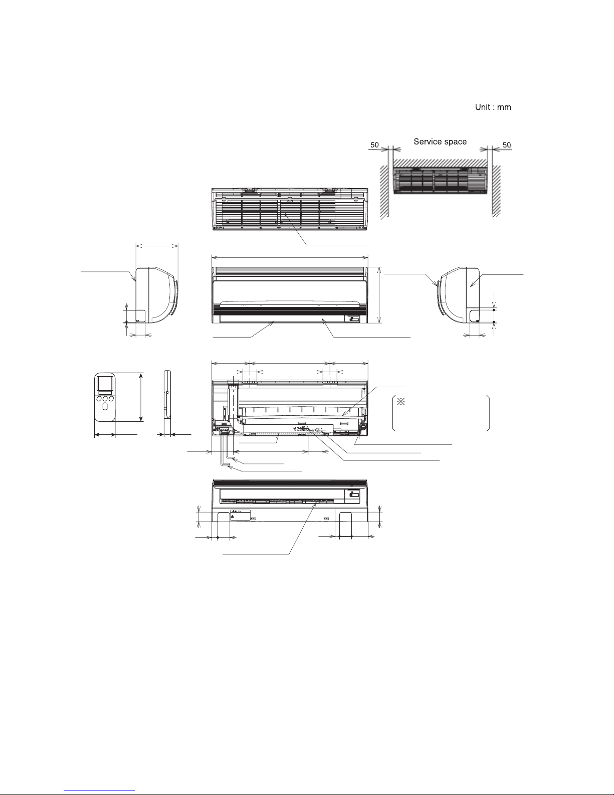
CONSTRUCTION AND DIMENSIONAL DIAGRAM
MODEL RAS-18YH6, RAS-25YH6
Top air suction grill
147
56 17.5
When piping is
drawn from the left side
,
exchange the drain
hose for the dr
ain cap
Mounting plate
Air outlet
Horizontal air diflector
Front panel
Cabinet
Drain
Drain cap connection port
Narrow pipe (ø6.35)
Wide pipe (ø9.52)
Drain hose
Power cord
Connecting cable
Vertical air deflector
INDOOR UNIT
Page 18
– 16 –
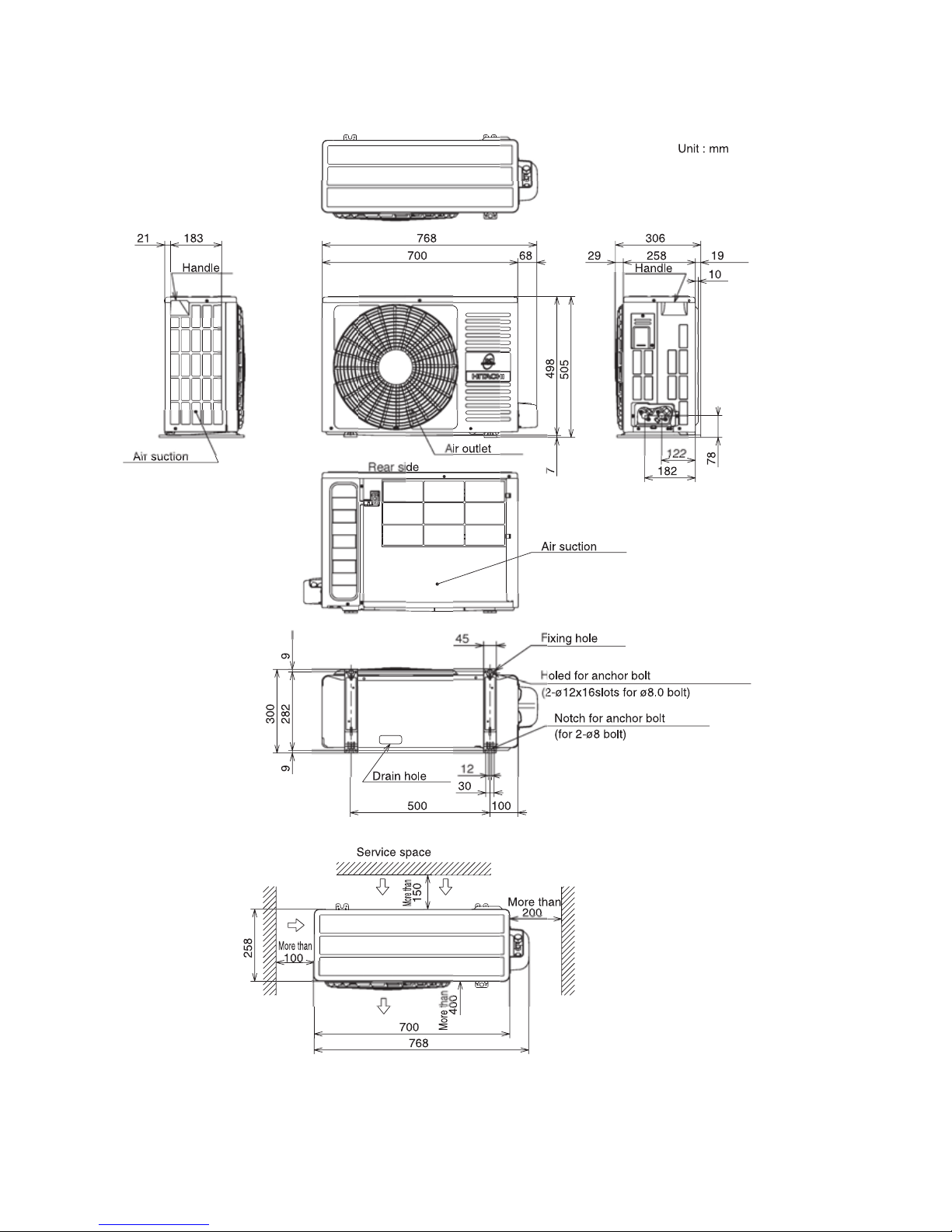
CONSTRUCTION AND DIMENSIONAL DIAGRAM
MODEL RAC-18YH6, RAC-25YH6
OUTDOOR UNIT
Page 19

– 17 –
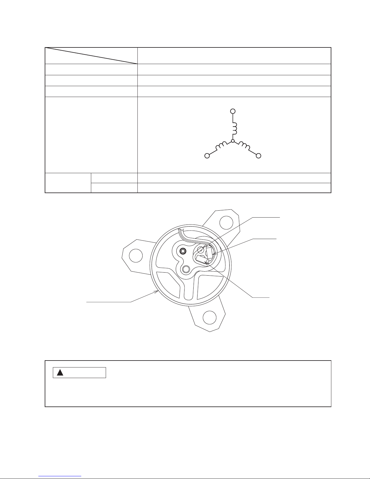
MAIN PARTS COMPONENT
THERMOSTAT
Thermostat Specifications
FAN MOTOR
MAIN ELECTRIC COMPONENTS FOR OUTDOOR UNIT
Fan Motor Specifications
CONNECTION
TEMPERATURE
°C (°F)
INDICATION
16
INDICATION
24
INDICATION
32
MODEL RAS-18YH6, RAS-25YH6
THERMOSTAT MODEL IC
OPERATION MODE COOL HEAT
ON 16.7 (62.1) 18.7 (65.7)
OFF 16.0 (60.8) 19.3 (66.7)
ON 24.7 (76.5) 26.7 (80.1)
OFF 24.0 (75.2) 27.3 (81.1)
ON 32.7 (90.9) 34.7 (94.5)
OFF 32.0 (89.6) 35.3 (95.5)
M
RED
BLK
WHT
YEL
BLU
35V
5V
0V
0 - 5V
FG
MODEL
NAME RATING APPLICABLE MODELS
REVERSING VALVE COIL 135 Ω (20 ˚C) RAC-18YH6, 25YH6
REACTOR L1 13 (mH), 0.224 Ω RAC-18YH6, 25YH6
REACTOR L2 25.5 (mH), 0.37 Ω RAC-18YH6, 25YH6
FILM CAPACITOR 45 (µF) RAC-18YH6, 25YH6
RAS-18YH6, RAS-25YH6
POWER SOURCE DC 5V, 35V
DC 140
- 350
V
OUTPUT 25W
40W
(Control circuit built in)
BLU : BLUE YEL : YELLOW BRN : BROWN WHT : WHITE
GRY : GRAY ORN : ORANGE GRN : GREEN RED : RED
BLK : BLACK PNK : PINK VIO : VIOLET
RED
140 350V
BLK
0V
WHT
15V
M
YEL
0-6V
BLU
0-15V
RAC-18YH6, RAC-25YH6
Page 20
– 18 –
WHITE
COMPRESSOR
YELLOW
RED
FRONT SIDE OF OUTDOOR UNIT
MODEL
ITEM
COMPRESSOR TYPE
POWER SOURCE
OUTPUT
COMPRESSOR MOTOR
Compressor Motor Specifications
WINDING
20°C
75°
C
RESISTANCE
(Ω)
!
CAUTION
When the refrigerating cycle has been operated for a long time with the capillary tubes clogged or crushed
or with too little refrigerant, check the color of the refrigerating machine oil inside the compressor. If the
color has been changed conspicuously, replace the compressor.
2M=1.15
2M=1.40
(U)
(V)
(W)
M
M
M
WHITE
YELLOW
RED
RAC-18YH6, RAC-25YH6
ASC092CD
800W
DC 270 - 350 V
Page 21
– 19 –
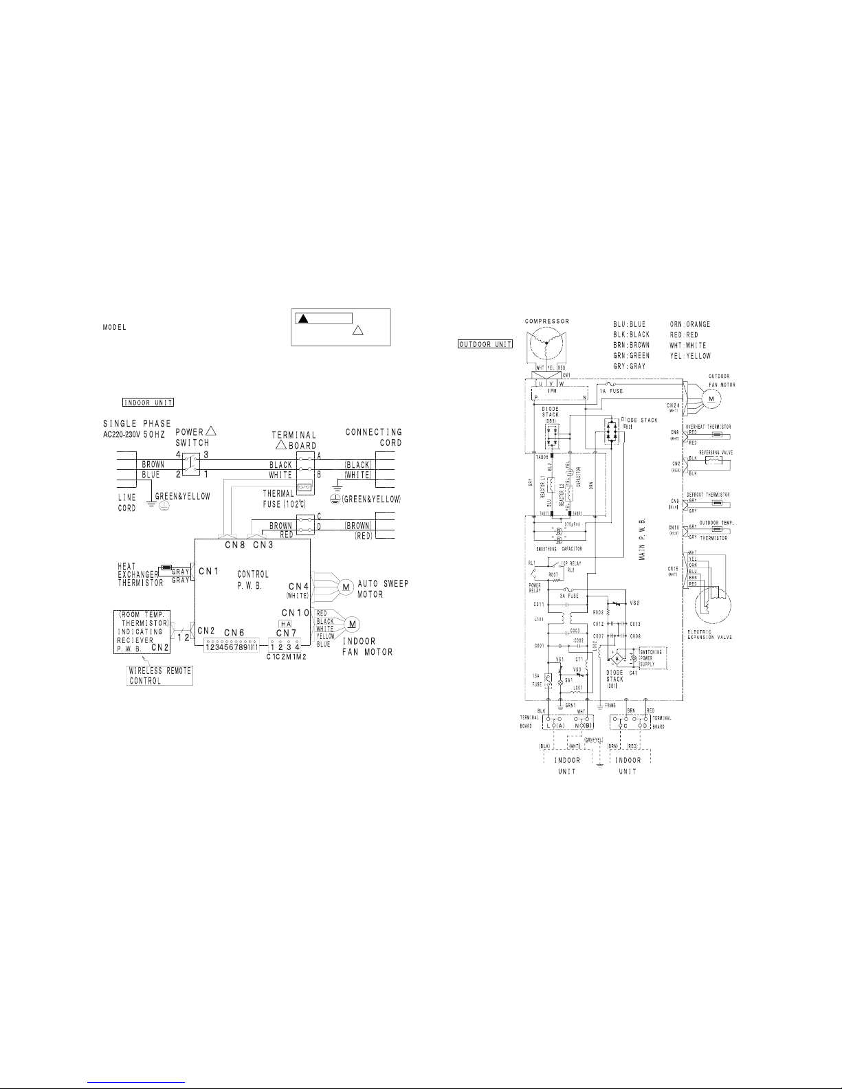
WIRING DIAGRAM
RAS-18YH6 / RAC-18YH6
RAS-25YH6 / RAC-25YH6
!
!
CAUTION
The marked parts are
very important ones for safety.
!
!
Page 22
– 20 –
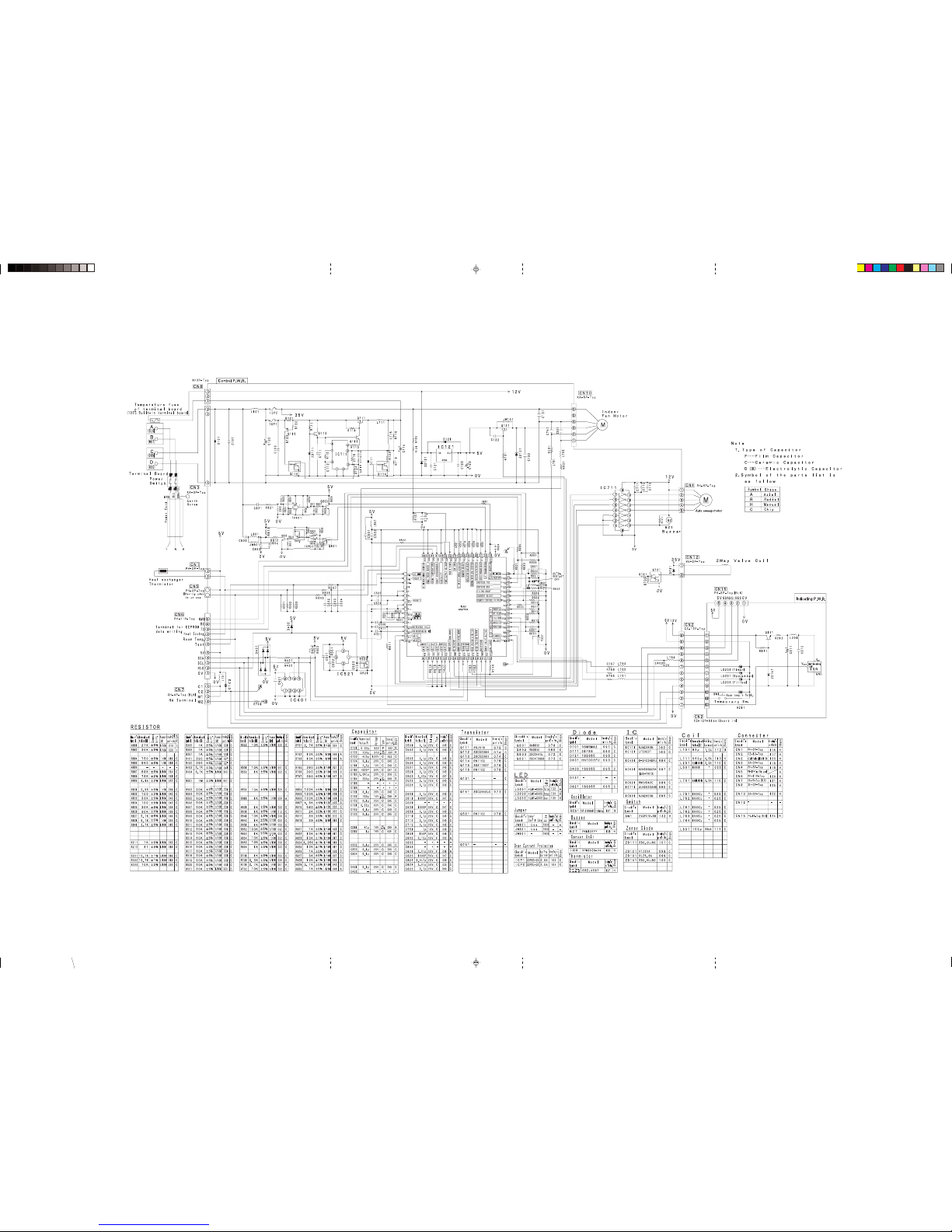
CIRCUIT DIAGRAM
MODEL RAS-18YH6, RAS-25YH6
RAS_AW_020-021_A2 11/17/06, 11:18 AM20
Page 23
– 21 –
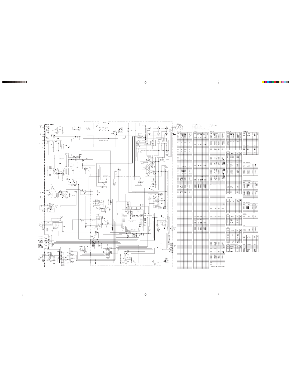
RAC-18YH6, RAC-25YH6
MODEL
RAS_AW_020-021_A2 11/17/06, 11:18 AM21
Page 24
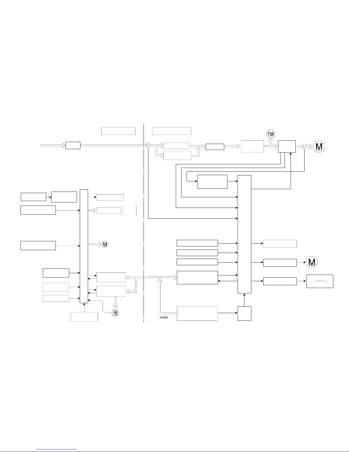
Wireless receive
circuit
Filter.
Operation.
Timer.
Auto sweep motor for
Air deflector
Remote controller
Heat exchanger
thermistor
Room temperature
thermistor
Reset circuit
Initial setting circuit
Temporary switch
Outdoor microcomputer (AX-8V11)
RAS-18YH6 / RAC-18YH6MODEL
RAS-25YH6 / RAC-25YH6
Indoor microcomputer (AX-7R13)
BLOCK DIAGRAM
INDOOR UNIT OUTDOOR UNIT
POWER RELAY
POWER
SWITCH
Inrush current
Protection circuit
HARMONICS
IMPROVEMENT
CIRCUIT
IPM
Rotor magnetic
pole position
detection circuit
lp
ld
ls
Buzzer circuit
Indicating lamp
Indoor/Outdoor
interface circuit
DC fan motor drive
circuit
Microcomputer clock
circuit
Indoor DC
fan motor
Overheat thermistor
Defrost thermistor
Outdoor temperature thermistor
Indoor/Outdoor
interface circuit
Reversing valve coil
Power circuit
Reset
circuit
Outdoor DC fan motor
RECTIFIER
DC compressor
motor
Relay drive circuit
Electric expansion valve
Reversing valve
control circuit
Power source
1ø 50Hz 220-230V
– 22 –
Page 25
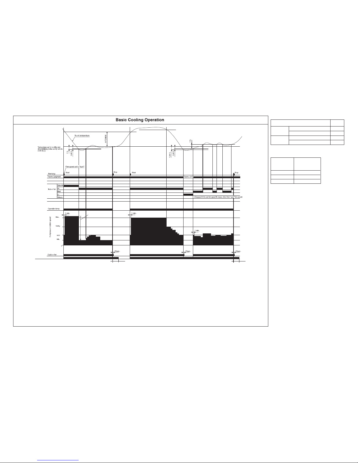
– 23 –
Page 26

– 24 –
Table 1 Mode data file
RAS-18YH6 RAS-25YH6
LABEL NAME VALUE
WMAX
3500 min
–1
4400 min
–1
WMAX2
3500 min
–1
4400 min
–1
WSTD
2950 min
–1
4200 min
–1
WBEMAX
2800 min
–1
3200 min
–1
CMAX
3200 min
–1
3200 min
–1
CMAX2
3200 min
–1
3200 min
–1
CSTD
2400 min
–1
2900 min
–1
CKYMAX
2300 min
–1
2700 min
–1
CJKMAX
2300 min
–1
2500 min
–1
CBEMAX
2300 min
–1
2300 min
–1
WMIN
2200 min
–1
2200 min
–1
CMIN
2200 min
–1
2200 min
–1
STARTMC
90 Seconds 90 Seconds
DWNRATEW
80% 80%
DWNRATEC
60% 60%
SHIFTW
2.00°C 2.00°C
SHIFTC
1.33°C 1.33°C
CLMXTP
30.00°C 30.00°C
YNEOF
25.00°C 25.00°C
TEION
2.00°C 2.00°C
TEIOF
9.00°C 9.00°C
SFTDSW
1.00°C 1.00°C
DFTIM1
43 Minutes 43 Minutes
DFTIM2
60 Minutes 60 Minutes
Page 27
Reversing valve (cooling “on” mode)
NO
TE (9)
Notes:
(1) Condition for entering into Cool Dashed mode. When fan set to “Hi” or “Auto mode” and temperature difference between indoor temperature and set temperature has a
corresponding compressor rpm (calculated value in Table 2) larger than CMAX.
(2) Cool Dashed will release when i) a maximum 25 minutes is lapsed and ii) room temperature is lower than set temperature –3°C (thermo off) and iii) when room temperature
has achieved setting temperature –1°C then maximum Cool Dashed time will be revised to 20 minutes. And iv) indoor fan is set to Lo and Med fan mode and v) change operation
mode.
(3) During Cool Dashed operation, thermo off temperature is set temperature (with shift value) –3°C. After thermo off, operation continue in Fuzzy control mode.
(4) Compressor minimum “ON” time and “OFF” time is 3 minutes.
(5) During normal cooling mode, compressor maximum rpm CMAX will maintain for 60 minutes if indoor temperature is lower than CLMXTP. No time constrain if indoor temperature
is higher than CLMXTP.
(6)
(7) When fan is set to “Med”, compressor rpm will be limited to CJKMAX.
(8) When fan is set to “Lo”, compressor rpm will be limited to CBEMAX.
(9) During Cool Dashed, when room temperature reaches set temperature –1°C compressor rpm is actual rpm x DWNRATEC.
Temperature
Calculated
difference
compressor rpm
1.66°C
2200 min
–1
2.00°C
2600 min
–1
2.33°C
3000 min
–1
CLMXTP
2min. 30sec.
2min. 30sec.
(with shift value)
Table 2 Compressor rpm
Item
Temperature
Room
temperature
Outdoor
temperature
30°C
32°C
32°C
33°C
Thermo judgment (ON)
Thermo judgment (OFF)
Thermo judgment (ON)
Thermo judgment (OFF)
Table 1 Thermo judgment
button
When fan speed setting on remote control is “Hi” or “Auto” mode, and both room and outdoor temperatures (data based on out door unit) meet temperature judgment
(Off) shown in the table 1, the compressor rpm will be limited to CKYMAX.
– 25 –
Page 28
Sleep button
Notes:
(1) The sleep operation starts when the sleep button is pressed.
(2) When the sleep button is set, the maximum compressor speed is limited to CBEMAX, and the
indoor fan is set to "sleep Lo".
(3) The indoor fan speed does not change even when the fan speed mode is changed.
(4)
If sleep operation is canceled by the cancel button or sleep button, all data is cleared.
1min.
Compressor speed
Horiz
ontal air
deflector
Shut
Horizontal
Facing down
Indoor fan
Outdoor fan
Timer lamp
Remote control (Sleep) ON
Hi
Med
Lo
Set to 7 hours
See basic
operation
Notes:
(1) The sleep operation starts when the sleep button is pressed.
(2) When the sleep button is set, the indoor fan is set to “sleep Lo”.
(3) The indoor fan speed does not change even when the fan speed mode
is changed.
(4)
If sleep operation is canceled by the cancel button or sleep button, all
data is cleared.
+
+
–1.33˚C
–0.66˚C
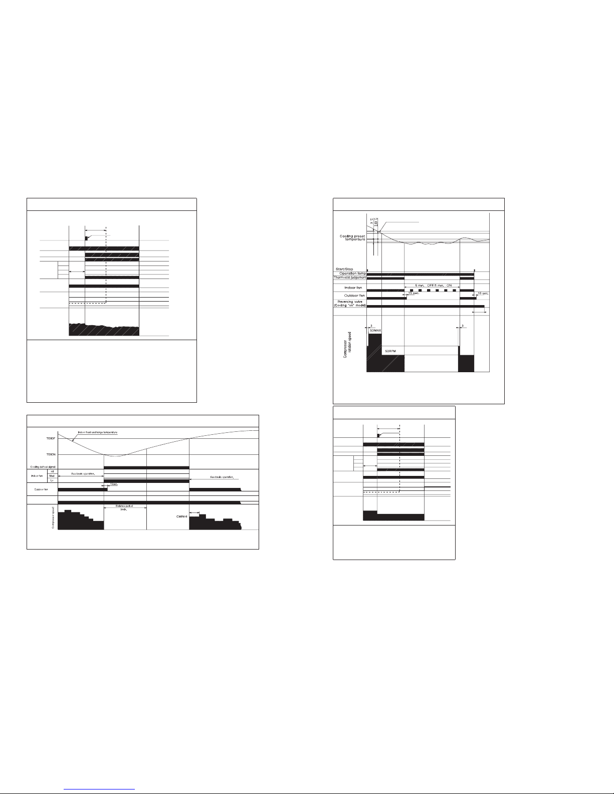
Notes:
(1) The operation is done assuming as the preset temperature
= (room temperature at the time) – (2°C).
(2) The indoor fan is operated in the “Lo” mode. During thermo OFF indoor fan will be OFF for 5
(3) When the operation is started by the themostat turning ON, the start of the indoor fan is
delayed 32 seconds after the start of compressor operation.
(4) The compressor is operated forcedly for 3 minutes after operation is started.
(5) The minimum ON time and OFF time of the compressor are 3 minutes.
minutes and ON for 1 minute.
Cooling Sleep Operation
Operation lamp
Cooling Defrost
Dehumidifying Operation
Start Stop
Dehumidifying Sleep Operation
Sleep button
Operation lamp
Timer lamp
Remote control (Sleep) ON
Indoor fan
See basic
operation
Hi
Med
Lo
Sleep Lo
Outdoor fan
Horizontal
air deflector
Shut
Horizontal
Facing down
Compressor speed
Set to 7 hours
SDMAX or SDRPM
7hr
STARCP
1hr
Sleep Lo
1 hr
7 hr
Room temperature
Reversing valve
(cooling "on" model)
button
Min
Min
2 min 30 sec.
– 26 –
Page 29
1.33˚C.
SFTDSW
0.66˚
C.
Fan speed set to "auto"
1 min.
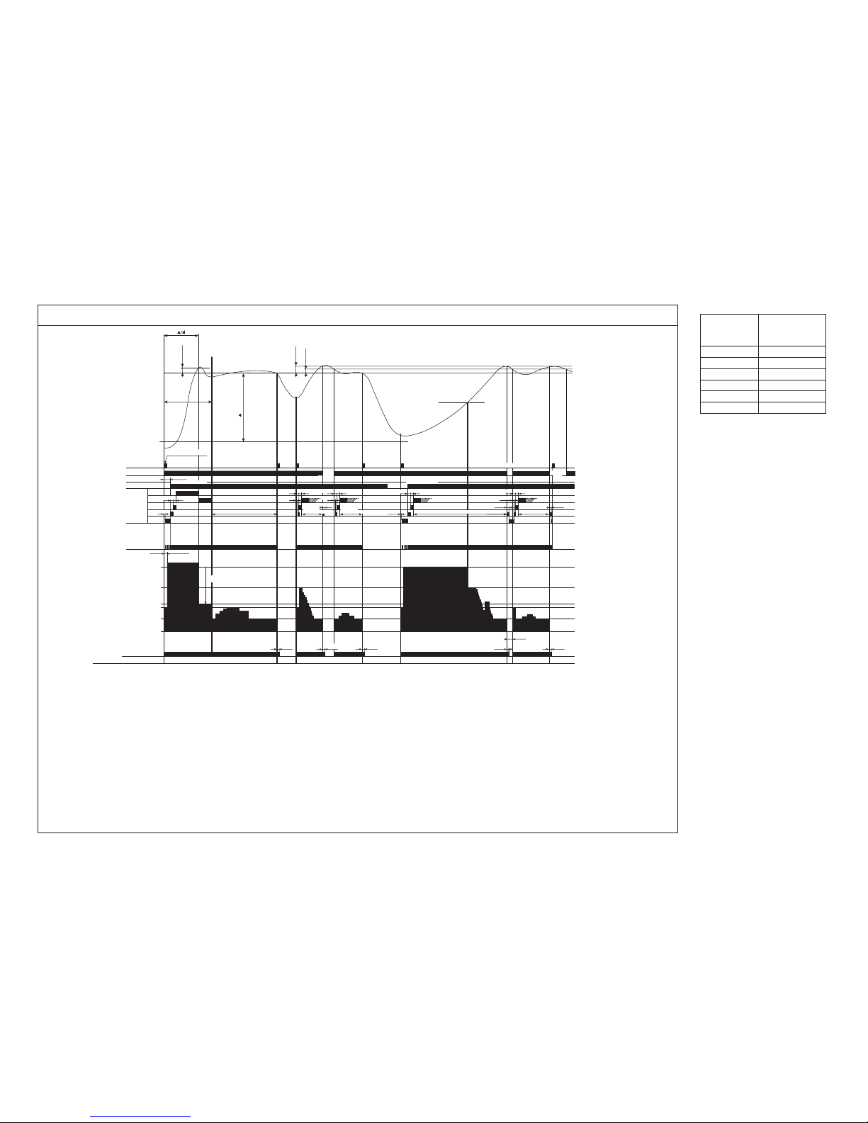
Basic Heating Operation
Start
Stop Start Start StopStop
Thermo
OFF
Thermo
OFF
Heating set temperature
(remote control set temperature
(+))
Start/stop button
Thermo judgment
Indoor fan
Ultra-Hi
Hi
Med
Lo
Ultra-Lo
Operation lamp
Max.
Rating
3000
0
Compressor speed
Outdoor fan
Reversing valve (cooling "on" model)
Ther
mo OFF
Dash period
TWMAX
Wtd
Defrost signal
Preheating judgment
30sec.
30sec.
10sec.
15sec. 15sec.
15sec. 15sec. 15sec.
10sec.
15sec.
15sec.
3min.
Max. 3 min.
Preheating released
Control by
heat exchanger temperature
Control by
heat exchanger temperature
15sec.
Control by
heat exchanger temperature
Control by
heat exchanger temperature
Control by
heat exchanger temperature
18˚C
10sec.
30sec.
30sec.
10sec.
30sec.
30sec.30sec. 30sec. 30sec. 30sec.
10sec.
Preheat released
WMIN
(WSTD)
(WMAX)
NOTE (10)
WMAX2
Notes:
(1) Condition for entering into Hot Dashed mode. When fan set to “Hi” or “Auto mode” and i) Indoor temperature is lower than 18°C, and ii) outdoor temperature is lower than 10°C,
and iii) Temperature difference between indoor temperature and set temperature has a corresponding compressor rpm (calculated value in Table 3) larger than WMAX.
(2) Hot Dashed will release when i) Room temperature has achieved the set temperature + SFTDSW. ii) Thermo off.
(3) During Hot Dashed operation, thermo off temperature is set temperature (with shift value) +3°C. After thermo off, operation continue in Fuzzy control mode.
(4) Compressor minimum “ON” time and “OFF” time is 3 minutes.
(5) During normal heating mode, compressor maximum rpm WMAX will maintain for 120 minutes if indoor temperature is higher than 18°C. No time limit constrain if outdoor temperature is
lower than 4°C.
(6) During Hotkeep or Defrost mode, indoor operation lamp will blink at interval of 0.5 seconds “ON” and 0.5 second “OFF”.
(7) When heating mode starts, it will enter into Hotkeep mode if indoor heat exchanger temperature is lower than YNEOF + 0.33°C.
(8) When fan is set to “Lo”, compressor rpm will be limited to WBEMAX. When fan is set to "Med", compressor rpm will be limited to WJKMAX.
(9) In “Ultra-Lo” fan mode, if indoor temperature is lower than 18°C, indoor fan will stop. If indoor temperature is higher than 18°C + 0.33°C, fan will continue in “Ultra-Lo” mode.
During Hotkeep or Defrost mode, fan will continue in “Ultra-Lo” mode.
(10) During Hot Dashed, when room temperature reaches set temperature + SFTDSW compressor rpm is actual rpm x DWNRATEW.
Temperature
Calculated
difference
compressor rpm
1.66°C2200 min
–1
2.00°C2600 min
–1
2.33°C3000 min
–1
2.66°C3400 min
–1
3.00°C3800 min
–1
3.33°C4200 min
–1
Table 3 Compressor rpm
Notes:
1. See the data in Table 1-Table 2 on
page 47 & 49 for each constant in
capital letters in the diagrams.
(with shift value)
– 27 –
Page 30

2min. 30sec.
Notes:
(1) The defrosting inhibit period is set as shown in the diagram below. When defrosting has finished once, the
inhibit period is newly set, based on the outdoor temperature when the compressor was started. During this
period, the defrost signal is not accepted.
(2) If the difference between the room and outdoor temperature is large when defrosting is finished, the
maximum compressor speed (WMAX) or (WMAX2) can be continued for 120 minutes maximum.
(3) The defrosting period is 12 minutes maximum.
(4) When operation is stopped during defrosting, it is switched to auto refresh defrosting.
(5) Auto refresh defrosting cannot be engaged within 15 minutes after operation is started or defrosting is
finished.
Sleep Lo
Notes:
(1) The sleep operation starts when the sleep button is pressed.
(2) When the sleep button is set, the maximum compressor speed is limited to WBEMAX, and the indoor fan is
set to "sleep Lo".
(3) The indoor fan speed does not change even when the fan speed mode is changed. (Sleep Lo)
(4) When defrosting is to be set during sleep oepration, defrosting is engaged and sleep operation is restored
after defrosting.
(5) If sleep operation is cancelled by the cancel button or sleep button, all data is cleared.
Reversing Valve Defrosting
Preheating released
Reversing valve
(cooling "on" model)
Heating Sleep Operation
Upper limit WBEMAX
Sleep button
– 28 –
Page 31

– 29 –
Page 32

– 30 –
2
1
7
3
5
NORMAL : HI
RESET : LO
RES
Microcomputer
C524
C522
C521
R551
IC521
0V
R552
5V
Power "OFF"
Power "ON"
Reset enter at 4.2V
Reset release at 4.4V
Voltage
Voltage
Voltage supply to
pin 2 of IC521
Voltage at pin 7
of microcomputer
5.0V
Fig. 1-2
Fig. 1-1
5.0V
DESCRIPTION OF MAIN CIRCUIT OPERATION
MODEL RAS-18YH6, RAS-25YH6
1. Reset Circuit
The reset circuit initializes the microcomputer program when power is ON or OFF.
Low voltage at pin
77
77
7 resets the microcomputer and Hi activates the microcomputer.
When power “ON” 5V voltage rises and reaches 4.4V, pin
11
11
1 of IC521 is set to “Hi”. At this time the microcomputer
starts operation.
When power “OFF” voltage drops and reaches 4.2V, pin
11
11
1 of IC521 is set to “Low”. This will RESET the
microcomputer.
Page 33

– 31 –
2. Receiver Circuit
IRR (light receiver unit) receives the infrared signal from the wireless remote controller. The receiver
amplifies and shapes the signal and outputs it.
3. Buzzer Circuit
When the buzzer sounds, an approx 3.9kHz
square signal is output from buzzer output pin
TT
TT
T
of the microcomputer. After the amplitude of this
signal has been set to 12Vp-p by IC711, it is
applied to the buzzer. The piezoelectric element in
the buzzer oscillates to generate the buzzer’s
sound.
Q141
L201
12V
IRR
VDD
Fig.2-1
Fig.3-1 Buzzer circuit
GND
V
OUT
C212
C211
R212
0V
0V
0V
R211
0V
ZD141
R141
R611
C611
0V
RECEIVER I/P
Microcomputer
13
BZ1
R721
12V
IC711
Microcomputer
Buzzer output
16130
BZ
Sound wave
Metal diaphragm
V
Pizoelectric element
V
Fig. 3-2 Buzzer Operation
Page 34

– 32 –
Micro computer pins
Step width : 10ms
Horizontal air deflectors
15
16
17
18
123456 78
Fig.4-2 Microcomputer Output Signals
Table 4-1 Auto sweep Motor Rotation
Mi
crocompute
r
7
1
N4
Roto
r
Auto sweep motor for
horizontal air defectors
Fig.4-1
Rotation angle per step ) Time per step (ms.)
0.0882 10Horizontal air deflectors
4. Auto Sweep Motor Circuit
Fig. 4-1 shows the Auto sweep motor drive circuit; the signals shown in Fig.4-2 are output from pin
EE
EE
E~
HH
HH
H of
microcomputer.
As the microcomputer’s outputs change as shown in Fig.4-2, the coils of the auto sweep motor is excite to turn the
rotor. Table 4-1 shows the rotation angle of horizontal air deflectors.
Page 35

– 33 –
5. Initial Setting Circuit (IC401)
• When power is supplied, the microcomputer reads the data in IC401 or IC402 (E2PROM) and sets
the preheating activation value and the rating and maximum speed of the compressor, etc. to their
initial values.
• Data of self-diagnosis mode is stored in IC401 or IC402; data will not be erased even when power is
turned off.
6. Power Supply
First, 35V power which operates the indoor unit is generated by the power source section of the outdoor unit and
supplied to the indoor unit through the C and D lines of the connecting cable.
Second, use the DC/DC converter and the 35 V power supply from the outdoor unit to generate 12 V control
power, which drives the stepping motor during the operation.
In addition, use the regulator IC 121 to generate 5 V power required for driving the micro computer and controlling
fan motor.
If the terminal block was overheated due to a connecting cable improper connection, the thermal fuse built in the
terminal block will burnt to shut off the 12 V line and stop the operation of the indoor unit. Then, the outdoor unit
cannot be communicated with the indoor unit and a communication error occurs (the outdoor LD301 will blink 9
times), stop all operations.
Fig. 6-1
Fig. 5-1
Microcomputer
External ROM
SCL
SDA
0V
0V
0V
5V
5V 5V
C401
IC401 or IC402 (E
2
PROM)
R404
R403
27
26
1
2
3
4
8
7
6
5
}
Page 36

– 34 –
7
51
7
51
63
1
N1
0
V
V
Micro computer
Fan motor
Fig. 7-1
DC fan
motor output
DC fan motor
Speed
feedback
Voltage at point A
Waveform
T2
T1
Voltage at point B
Waveform
T1
Voltage at point C
Waveform
T2
Fig. 7-2
Voltage at point B (V)
Fig. 7-3
7. Fan Motor Drive Circuit
• For the point A , 15.7 kHz PWM pulse will be output from
the pin
NN
NN
N on the micro computer as shown in Fig. 7-2.
The pulse range will vary with different command speed.
• The pulse is converted into the analog voltage by the
R751 and C751 and applied to the fan motor as the speed
command voltage.
Fig. 7-3 shows the relation between the voltage at the
point B and the speed. (Some differences will occur
due to the condition of the unit.)
• The fan motor outputs the feedback pulse of the speed,
which is input into the pin
DD
DD
D on the micro computer. This
pulse is equivalent to a frequency of 12/60 speed.
(Example: 1000 min-1 x 12/60 = 200 Hz)
The micro computer monitors the frequency and adjusts
the output pulse range of the pin
NN
NN
N so as to keep the
command speed.
• If the feedback pulse is 100 min-1 or less due to a locked fan motor or failure, the fan output will be
stopped temporarily as fan lock error. After 10 seconds, restart the output of the pulse. If fan lock
error is detected twice within 30 minutes, all units are stopped and the unit will come in the failure
mode. (The timer lamp will blink 10 times.)
Page 37

– 35 –
MODEL RAC-18YH6 RAC-25YH6
1. Power circuit
This circuit is to convert the power from AC which is provided from the terminal A and B to DC voltage.
And produces an AC current which does not exceed the harmonic amplitude limit of the IEC61000-3-2.
When the compressor is stopped, the AC voltage becomes about 300 V and while the compressor
operates, it is about 280 V.
Main parts
(1) DB2
The DB2 rectifies the AC voltage.
The possible causes for the DB2 failure are as follows. The 15 A fuse may be blown out or the IPM
for the main P.W.B. may have a failure. In such a case, check the 15 A fuse for blowout and replace
the main P.W.B. if necessary.
(2) DB3, L1, C023 and L2
The DB3, L1, C023 and L2 shape waveform of the input current.
When the current runs through the L1 is taken for I1 and the current runs through the L2 is taken for
I2 as shown in Fig. 1-2, I1 becomes an input current to the capacitor which peak value was crushed
by the L1 and I2 becomes a resonance current which causes the LC resonance using the L2 and
C023. By combining the I1 and I2, the input current from the main power shapes a waveform shown
in the right side of Fig. 1-3, indicating that the waveform is similar to sine wave. The more the
waveform is similar to the sine wave, the lower the harmonic current becomes.
If the C023 has any failure, the protection unit activates and the C023 in open mode. In such a case,
replace the failed parts.
1-2 1-3
+
I
1
I
2
I
S
I
1
I
2
L1
L2
DB3
C023
Page 38

– 36 –
Input
Voltage
0V
0V
0V
Voltage
Smoothed
Voltage
Fig. 1-4
(3) C021 and C022
This smoothes the voltage rectified for operating the
compressor.
When the input voltage is taken for the sine wave as
shown in the top of Fig. 1-4, it is rectified by the DB2
and becomes the waveform as shown in the middle
of Fig. 1-4. After that, the voltage is smoothed by the
C021 and C022, and becomes the waveform shown
in the bottom of Fig. 1-4.
(4) DB1 and C41
The DB1 rectifies the input voltage and the C41
smoothes it for the control power supply.
If the units above have any failure, the control power
supply won’t operate. In such a case, replace the
main P.W.B.
(5) C001 to C003, C011, L101, and L102
They absorb electrical noise generated during
operation of compressor, and also absorb external
noise entering from power line to protect electronic
parts.
Be sure to connect the earth cable between the indoor unit and the outdoor unit. Otherwise, the
noise filter circuit won’t operate properly.
(6) SA1 and VS1 to VS3
These surge absorber and varistors absorb external power surge such as induced thunder.
Be sure to connect the earth cable between the indoor unit and the outdoor unit. Otherwise, the
surge absorber and the varistors won’t operate.
(7) R002 and R007
The resistor R002 protects the rush current when the power is turned on while the resistor R007
protects the rush current when the compressor starts.
When the R002 has any failure, the control power supply won’t operate. When the R007 has any
failure and a strong rush current is generated, the DB2, C021 or C022 may be damaged.
Page 39

– 37 –
2. Indoor/Outdoor Interface Circuit
The interface circuit superimposes an interface signal on the DC 35V line to perform communications
between indoor and outdoor units. This circuit consists of a transmitting circuit which superimposes an
interface signal transmit from the microcomputer on the DC 35V line and a circuit which detects the
interface signal on the DC 35V line.
Communications are performed alternatively transmitting and receiving.
2-1 Communication signal from outdoor microcomputer to indoor microcomputer.
At first outdoor microcomputer will send a request signal (SDO) to indoor microcomputer.
38 KHz of carrier signal is generated and modulated by the request signal (SDO) from the outdoor
microcomputer pin
hh
hh
h.
This signal is superimposed to DC 35V line via C801 and L801.
To prevent erroneous reception, the outdoor microcomputer is designed so that it cannot receive a
signal while it is outputting a request signal.
The receiving circuit in the indoor unit consists of a comparator and transistor. The interface signal
from the outdoor unit on the DC 35V line is supplied to C821, where DC components are eliminated,
and is then shaped by the comparator. The shaped signal is detected by diode, amplified by amp,
and output to pin
ii
ii
i of the indoor microcomputer.
Fig. 2-2 shows the waveforms at each component when data is transferred from the outdoor
microcomputer to the indoor microcomputer.
2-2 Communication signal from indoor microcomputer to outdoor microcomputer.
The request signal (SDO) generates by indoor microcomputer is output to pin
jj
jj
j , and amplifies by
Q801.
I/F signal approx. 38 kHz is generated by comparator, then modulated by the signal from pin
jj
jj
j of
indoor microprocessor.
This modulated I/F signal is then amplified and superimposed to DC 35V line via L801 and C802 of
indoor interface circuit.
Fig. 2-3 shows the waveforms at each component when data is transferred from outdoor
microcomputer to indoor microcomputer.
The circuit operation of the outdoor receiving circuit is same as indoor receiving circuit.
Page 40

– 38 –
Fig. 2-1 shows the interface circuit used for the indoor and outdoor microcomputers to communicate
with each other.
(SDO)
I/F TRANSMISSION
(SDI)
I/F RECEPTION
48
C213
R255
R254
Q205
0V
0V
5V
R256
R214
R257
D206
IC5(1/2)
4
6
R260
R261
R258
R259
R262
0V
5V0V
R263
Q204
R268
5V
6.5V
0V
R803
Q801
R801
R802
C802
C801
L801
I / F0V
NF COIL 2
C808
L802
0V
12V
(Communications from indoor microcomputer to outdoor microcomputer)
(Communications from outdoor microcomputer to indoor microcomputer)
Fig. 2-1 Indoor / Outdoor interface circuit
CONTROL P.W.B .
C807
C806
35V
28
27
5
7
51
Page 41

– 39 –
ms.
1
f
rame
.95ms.
T
ransmit/receive
witching time
V
0
V
0
V
V
0
V
V
V
35
V DC lin
e
Fig. 2-3 Voltages Waveforms of Indoor / Outdoor Microcomputers (Indoor to Outdoor Communications)
48
5
50
49
ms.
1
f
rame
ms.
eade
r
V
V
V
35V D
C
lin
e
V
0
V
V
V
Fig. 2-2 Voltages Waveforms of Indoor / Outdoor Microcomputers (Outdoor to Indoor Communications)
48
5
50
49
Page 42

– 40 –
Fig. 2-4
1
)
Outdoor microcomputer
(
HIC
)
to indoor microcompute
r
Serial Communications Format during Normal Communications
xampl
e
When the outdoor message is all 0s
and indoor message is all 1s:
3
)
Communications waveforms
eade
r
ms
.
eade
r
ms
.
hen rese
t
approx.100ms.
)
hen rese
t
approx.10ms.
)
.
3
ms
.
NO
Bit No.=
0
it No.=
0
33.3ms.
)
33.3ms.
)
33.3ms.
)
ansmit
/
eceiv
e
witching tim
e
4.95ms.
)
33.3ms.
)
33.3ms.
)
Outdoor messag
e
ndoor messag
e
33.3ms.
)
33.3ms.
)
Character No
.
2
)
I
n
door microcomputer to outdoor microcomputer
(
HIC
)
Page 43

– 41 –
1
1
12126
1
0
123456
2
3
22
7
3
22
7
3
0202
7
6
3
22
7
01234
123
6
01234
123
6
6
0
1
Operation mode(0 LSB)
Operation mode(1)
Fan(0 LSB)
Fan(1)
Fan(2 MSB)
2-way valve
Reversing valve
Quick heating
Main power ON request
Operation mode(2 MSB)
Indoor in-operation bit
Capacity code(0 LSB)
Capacity code(1)
Capacity code(2)
Capacity code(3 MSB)
During forced operation
Defrost request signal
Self-diagnosis(1)
Self-diagnosis(0 LSB)
Outside temperature(0 LSB)
Actual compressor rotation speed(0 LSB)
Compressor command speed(0 LSB)
Compressor minimum rotation speed(0 LSB)
Compressor minimum rotation speed(1)
Compressor minimum rotation speed(2)
Compressor minimum rotation speed(3)
Compressor minimum rotation speed(4 MSB)
Compressor command speed(1)
Compressor command speed(2)
Compressor command speed(3)
Compressor command speed(4)
Compressor command speed(5)
Compressor command speed(6)
Compressor command speed(7 MSB)
15/20(A)
OVL up
Indoor new communication bit
Compressor ON
Actual compressor rotation speed(1)
Actual compressor rotation speed(2)
Actual compressor rotation speed(3)
Actual compressor rotation speed(4)
Actual compressor rotation speed(5)
Actual compressor rotation speed(6)
Actual compressor rotation speed(7 MSB)
Outdoor new communication bit
Rotary reversing valve being ON
Fast feed 1/1000 for commercial test
Fast feed 1/10000 for commercial test
Outside temperature(1)
Outside temperature(2)
Outside temperature(3)
Outside temperature(4)
Outside temperature(5)
Outside temperature(6)
Outside temperature(7 MSB)
Fan-7-step request
Self-diagnosis(3 MSB)
Self-diagnosis(2)
Page 44

– 42 –
Fig. 3-1 System power module circuit (U
+
is ON, V
-
is ON)
3. Intelligent power module circuit (IPM circuit)
Fig. 3-1 shows peripheral circuits of intelligent power
module (IPM).
In the diagram, U
+
,V
+
and W
+
are called the
"upper arm", U
-
, V
-
and W
-
, the "lower arm".
Page 45

– 43 –
Fig. 3-3 Voltage waveform at each point
transistor chopped
hopping period (208µ sec.
)
hopping perio
d
transistor ON
80V-300
V
urrent a
t
O
N
A
B
m
e
W
T
pper ar
m
transistor
Lower arm
trans
i
stor
++
Fig. 3-2 Switching order of power module
Intelligent power module switches power supply current according to position of the compressor motor
rotor.
The switching order is as shown in Fig. 3-2.
At point E: U+ is ON, V- is ON (circuit in Fig. 3-1)
At point F: U+ is chopped (OFF), V- is ON (circuit in Fig. 3-4)
Upper arm transistor is controlled to ON/OFF by 2.5kHz-5kHz chopper signal. Rotation speed of the
compressor is proportional to duty ratio (ON time/ ON time + OFF time) of this chopper signal.
Time T in Fig. 3-2 shows the switching period, and relation with rotation speed (N) of the compressor is
shown by formula below;
N = 60/2 X 1/T
Fig. 3-3 shows voltage waveform at each point shown in Figs. 3-1 and 3-4. First half of upper arm is
chopper, second half is ON, and first half of lower arm is chopper, second half is ON.
When power is supplied U+→ V- , because of that U+ is chopped, current flows as shown below;
(1) When U+ transistor is ON: U+ transistor → U coil → V coil → V- transistor → DC current detection
resistor → Point B (Fig. 3-3)
(2) When U+ transistor is OFF: (by inductance of motor coil) U coil → V coil → V-transistor →
U- diode → Point A (Fig. 3-4)
Page 46

Fig. 3-4 Power module circuit (U+ is OFF, V– is ON)
303
302
301
.
R
V
C
Since current flows at point B only when U
+
transistor and V– transistor are ON, the current waveform
at point B becomes intermittent waveform as shown in Fig. 3-3. Since current at point B is approximately
proportional to the input current of the air conditioner, input current is controlled by using DC current
(Id) detection resistor.
<Reference>
If power module is defected, self diagnosis lamps on the MAIN P.W.B. may indicate as shown below:
MAIN P.W.B
D
D
D
SE
PM
HI
ICE SWITCH
Table 3-1
Fig. 3-5
– 44 –
Page 47

– 45 –
Page 48

– 46 –
Page 49

– 47 –
5. Power Circuit for P.W.B.
• Fig. 5-1 shows the power circuit for P.W.B.
• In the power circuit for P.W.B., power supply for microcomputer, peripheral circuits, and IPM driver
circuit and, as well as DC 35V, are produced by switching power circuit.
• Switching power circuit performs voltage conversion effectively by switching transistor IC1 to convert
DC 330V voltage to high frequency of about 20kHz to 200kHz.
ig. 5-
1
AC220-230V
Page 50

– 48 –
Page 51

– 49 –
Page 52

– 50 –
Page 53

– 51 –
6-2. Overload control circuit (OVL control circuit)
Overload control is to decrease the speed of the compressor and reduce the load when the load on
the air conditioner increases to an overload state, in order to protect the compressor, electronic
components and power breaker.
Overloads are judged by comparing the DC current level and set value.
Fig.6-4 shows the overload control system configuration and Fig. 6-7 is a characteristic diagram on
overload judgement values. There are two types of control which has named IS OVL and ID OVL.
IS OVL is limiting the whole input of this room air conditioner system through the current sensor CT1
in order to keep the maximum rating of components by reading total operating current.
ID OVL is watching and limits the compressor current through the detection resistor, which is built in
IPM in order to control the compressor reliability. Since the compressor reliability is related with its
speed, the ID OVL value is also linked with the compressor speed. Fig. 6-7 shows an ID OVL limitation
curve.
All of OVL operation values were programmed into EEPROM memory.
Compressor
Microcomputer EEPROM
Motor current (ID)
Whole current (IS)
Fig. 6-4 Overload Control System
Detection
resistor
A-D
converter
ID OVL
value
IS OVL
value
Motor
control
process
A-D
converter
Detection
transformer CT1
Amplifier
Smoother
Page 54

– 52 –
Page 55

– 53 –
IPM
DC current
P
DC
Voltage
N
Detection
resistor
U
+
---
V
+
W
+
UVW
U
V
W
Compressor motor
Fig. 6-9
DC voltage : Low
DC current : High
DC voltage : High
DC current : Low
DC voltage : 260V
Rotation speed
DC current
0
0
Fig. 6-8
R003,R004,R608,R613, detect the DC voltage at the power circuit. The microcomputer receives a DC
voltage and applies correction to the overload set value so the DC current will be low when the DC
voltage is high.
(Since the load level is indicated by the DC voltage multiplied by DC current, R247, R248, R249 are
provided to perform the same overload judgement even when the voltage varies.)
(3) Start current control
It is required to maintain the start current (DC current) constant to smooth the start of the DC motor
of the compressor.
RAC-18YH6, RAC-25YH6 uses software to control the start current.
The start current varies when the supply voltage varies. This control method copes with variations in
the voltages as follows.
1. Turns on the power module’s U
+
and V- transistors so the current flows to the motor windings as
shown in Fig. 6-9.
2. Varies the turn-ON time of the U
+
transistor according to the DC voltage level and the start is
controlled so the start current is approx. 10A .
Page 56

– 54 –
Fig. 6-10
HIC
Microcomputer
RESET OUT.
RESET
19
7
C204
0V
R252
1
0V
8
2
3
IC5(1/2)
+
-
5V
D208
R287
C215
R284
R286
C225
R285
C226
R292
R289
R288
0V 0V 0V 0V
12V
Fig. 6-11
12V line
12V line
5V line
5V line
Reset voltage
Reset voltage
Time
Time
10.9V
9.9V
12
6
0
12
6
0
Power is ON
Voltage (V)
Power is OFF
Voltage (V)
6-3. Reset Circuit
The reset circuit initializes the microcomputer program when Power is “ON” from “OFF” .
Low voltage at pin 7 resets the microcomputer, and HI activates the microcomputer.
Fig. 6-10 shows the reset circuit and Fig. 6-11 shows waveform at each point when power is turned on
and off.
When power is turned on, 12V line and 5V line voltages rise and 12V line voltage reaches 10.9V an
reset voltage input to pin 7 of microcomputer is set to Hi.
Reset voltage will be hold “Hi” until the 12V line voltage drops to 9.90V even though the power shuts
down.
Page 57

– 55 –
Outdoor temperature
.
19.69.23
.
75
.
22.62
R303 Voltage (V
O
C
)
Table 6-2
-
Main P.W.B.
HIC
O.H. thermistor
DEF. thermistor
Outdoor temperature
thermistor
Microcomputer
AX-8V11
OH
DEF
Outdoor
temperature
59
63
64
0V
0V
0V
C302
0V
R303
R306
0V
R302
R305
C303
C304
R304
R301
0V
CN8
CN9
+5V
+5V
+5V
CN10
1
2
1
2
1
2
20
21
22
Fig. 6-12
6-4. Temperature Detection Circuit
The Over heat thermistor circuit detects the temperature at the surface of the compressor head, the Defrost.
thermistor circuit detects the defrosting operation temperature.
A thermistor is a negative resistor element which has the characteristics that the higher (lower) the temperature,
the lower (higher) the resistance.
When the compressor is heated, the resistance of the Over heat thermistor becomes low and voltage to a
pin s of microcomputer is increased.
Microcomputer compares the voltage at pin s with the internal set value, if it is exceeded the set value
microcomputer judges that the compressor is overheated and stops operation.
When frost forms on the outdoor heat exchanger, the temperature at the exchanger drops abruptly. Therefore
the resistance of the Defrost. thermistor becomes high and the voltage at pin w of microcomputer drops.
If this voltage becomes lower than the set value stored inside, the microcomputer starts defrosting control.
During defrosting operation the microcomputer transfers the defrosting condition command to the indoor
microcomputer via the circuit interface.
The microcomputer always reads the outdoor temperature via a thermistor (microcomputer pin x ), an
transfers it to the indoor unit, thus controlling the compressor rotation speed according to the value set at the
EEPROM in the indoor unit, and switching the operation status (outdoor fan on/off, etc.) in the dehumidifying
mode.
The following shows the typical values of outdoor temperature in relation to the voltage:
<Reference>
When the thermistor is open, in open status, or is disconnected, microcomputer pins s,w,x are approx.
0V; when the thermistor is shorted, they are approx. 5 V, and LD301 blinks seven times.
However, an error is detected only when the OH thermistor is shorted; in such a case, the blinking mode
is entered 12 minutes after the compressor starts operation.
Page 58

– 56 –
CN2
7
015V
IC2
6-5. Reversing valve control circuit
In this unit, reversing valve control circuit turns ON/OFF the power to the reversing valve coil by
opening/closing the reversing valve relay.
Opening/closing of relay will differ depending on the operation condition. (In the cooling cycle,
reversing valve relay is normally ON (close).)
Table 6-3 shows the circuit operation of each operation mode. If the following result is not obtained,
reversing valve control circuit may be defective.
Table 6-3
Point
Operation mode
Cooling
In normal cooling operation
In normal heating operation
In defrosting operation
approx. 35 V
approx. 35 V
0VHi
0VHi
12VLo 0V (not fixed)
Heating
Between Pin 29
of microcomputer and 0V
Between Pin 32 of HIC
and 0V
Between 1 and 3 CN2
Main P.W.B.
Reversing
valve
Reversing valve
relay coil
(RL5)
HIC
Fig. 6-13
Microcomputer
Reversing valve relay
RL5
−
−
Page 59

– 57 –
IC6
HIC
6-6. Electric expansion valve control circuit
Electric expansion valve is driven by B-12V. Opening of the valve is controlled by feeding power to 1
or 2 phases of the 4-phase coil to switch the polarity of the coil.
The relation between the conducting phase switching direction and open/close direction is as shown
below. When the power is turned on, approx. 0.9 V is applied to CN15 pins 1 to 4 ; when no power
is supplied, approx. 12 V is applied. When the power is reset, expansion valve performs initial
operation for 5 to 10 seconds.During initial operation, measure pins 1 to 4 of CN15 using
multimeter: If no change is found around 0.9 V or 12V, expansion valve or microcomputer is
defective.
Fig. 6-15 shows logic waveform during the operation of expansion valve.
1
2
3
4
1
2
3
4
Page 60

– 58 –
6-7. Outdoor DC
an Motor contl circui
t
This model uses DC Fan Motor which has a controller circuit built in the Motor
.
This DC Fan Motor will rotate by control voltage apply to
sp input
.
(V
(Voltage range: 1.7 to 7V DC
)
Motor will output FG pulse byollowing this motor reolution
.
indoor microcompute
r
This PWM control signal will convert to Vsp voltage by smoothing circuit. (R242 & C209)
otation speed
.
C Fan Motor circuit has to match the Fan Motor revolution with instructed revolution. Such as..
.
G feedback: Fasternstruction: Slower ... Decrease pulse width
G
edback
Slowernstruction: Faster ... Increase pulse width
G pulse is also used for Fan Motor failure detection
.
Microcompute
r
w
ill monitorG pulse
econds aftera
r
t
thefan moto.
there is no
ignal detected
,
it
considerthat the
an Moto
r
w
a
malfunction and
op the operation.n this case,
D
302
on main
107 and IC4 are used for Fan Motorover curren
t.
sp high
aster ;
lower ;
V
o
p
.W.B. will blink 12 times.
Fan Motor lock detected
)
G pulse will feed back to Outdoor microcomputer
.
Outdoor microcomputer will output PWM control signal from
by following the instruction from
an motor will start to rotate when Vsp was proceeding over than 1.7V, and generate FG pulse b
y
1
24
53
46
45
44
HIC
Page 61

– 59 –
< Reference >
When operation stop with LD301 blinks 12 times, it may be caused by faulty DC fan motor.
In this case, please check CN6 and CN12 connection first. It makes Fan Motor Lock also if those
connectors are in misconnection.
DC Fan Motor has broken invites 1A Fuse burned. Please replace both DC Fan Motor and 1A Fuse
together.
It will makes “Fan Lock Stop” when something has disturb the Fan rotation by inserting materials into
propeller fan or ice has growing inside of outdoor unit by snowing.
It may make “Fan Lock Stop” by strong wind (ex. 17m/sec or above) against the Fan rotation. In this case
unit will be restart again after a while.
In case of “ Fan Lock Stop” even though the DC Fan Motor is rotating correctly, the possible cause in Fan
Motor problem or control board problem. Stop after the Fan motor runs 2 minutes, Fan Motor may be
broken.
< Caution >
Please take care for the electrical shock by high voltage of DC Fan Motor power source which is common
with compressor when you are servicing this unit.
You can not confirm the coil and wiring of Motor directly due to the built in control circuit in Fan Motor.
Page 62

– 60 –
SERVICE CALL Q & A
Model RAS-18YH6 / RAC-18YH6
RAS-25YH6 / RAC-25YH6
COOLING MODE
The compressor has
Fan speed is not switched over
during dehumidifying operation.
Cool air comes from the unit during
dehumidifying operation.
Fans speed is normally set to LOW during
dehumidifying operation.
To have an operation with high dehumidifying
effect, the unit operates at low fan speed.
As a result, cool air comes from the unit.
This phenomenon is not a fault.
stopped suddenly during
cooling operation.
The circulation stops
occasionally during
Heating mode.
When the fan speed is set
at HIGH or MED, the flow
is actually Weak.
Heating operation stops
When “Auto fan” mode is set,
the indoor fan speed changes
from HIGH through MED to
LOW.
while the temperature is
preset at "30".
Check if the indoor heat
exchanger is frosted.
Wait for 3-4 minutes
until it is defrosted.
If the air conditioner operates
in cooling mode when it is
cold, the evaporator may get
frosted.
It occurs during defrosting. Wait for 5-10
minutes until the
condenser is defrosted.
At the beginning of heating,
the fan speed remains
LOW for 30 seconds. If
HIGH is selected, it
switches to LOW and again
to MED after additional 30
seconds.
If temperature is high in
This is not an error.
The anti cool air function
shows this phenomenon.
In the fan “Auto” mode, the unit
detects the heat exchange
temperature. When the
temperature becomes low,
the fan speed changes from
HIGH, through MED to LOW.
the outdoor, heating
operation may stop to
protect internal devices.
DEHUMIDIFYING MODE
HEATING MODE
Q1
A1
Q2
A2
Q3
A3
Q4
A4
Q5
A5
Q6
A6
Q7
A7
Page 63

– 61 –
AUTO FRESH DEFROSTING
AUTO OPERATION
NICE TEMPERATURE RESERVATION
INFRARED REMOTE CONTROL
After the ON/OFF button is pressed
to stop heating, the outdoor unit is
still working with the OPERATION
lamp lighting.
Fan speed does not change when
fan speed selector is changed
during auto operation.
When on-timer has been
programmed, operation starts before
the preset time has been reached.
Does Nice temperature reservation
function operate during dehumidifying?
Even if the same time is preset,
the operation start time varies.
Timer cannot be set.
The current time display
disappears soon.
The timer has been programmed,
but the preset time disappears.
Auto Fresh Defrosting is carried out : the
system checks the outdoor heat exchanger
and defrosts it as necessary before stopping
operation.
At this point fan speed is automatic.
This is because Nice temperature reservation
function is operating. This function starts
operation earlier so the preset temperature is
reached at the preset time. Operation may start
maximum 60 minutes before the preset time.
It does not work. It works only during cooling
and heating.
This is because Nice temperature reservation
function is operating. The start time varies
according to the load of room. Since load varies
greatly during heating, the operation start time is
corrected, so it will vary each day.
Has the clock been set? Timer cannot be set
unless the clock has been set.
The current time disappears
in approx. 10 seconds. The
time set display has priority.
approx. 3 minutes.
Is the current time past the preset time?
When the preset time reaches the current
time, it disappears.
When the current time is
set the display flashes for
Q8
A8
Q9
A9
Q10
A10
Q11
A11
A12
Q13
A13
Q14
A14
Q15
A15
Q12
Page 64

– 62 –
OTHERS
Q18
A18
Q19
A19
Q20
A20
Q21
A21
Q22
A22
The indoor fan varies among
high air flow, low air flow and
breeze in the auto fan speed
mode. (Heating operation)
This is because the cool
wind prevention function
is operating, and does
not indicate a fault.
The heat exchanger temperature
is sensed in the auto speed mode.
When the temperature is low, the
fan speed varies among high air
flow, low air flow and breeze.
Loud noise from the outdoor unit is
When the “Sleep” timer is set during
operation,
(1) The indoor fan won’t rotate.
(No air comes from the unit)
(2) The air speed won’t change.
The preset temperature is not
indicated on the remote control.
(1) The temperature arrives at the preset indoor
temperature and the air conditioner unit is
temporarily stopped. Within about 3 minutes,
the fan starts rotation.
(2) When the unit operates at “LOW” air speed,
it continues to operate at the same speed.
When automatic operation is performed, the
preset temperature won’t be indicated.
However, you can adjust the temperature within
a range of ±3°C by pressing the “Room
Temperature” button.
If the temperature is 1°C higher than the auto
preset temperature, 1°C will appear.
If the temperature is 1°C lower than the auto
preset temperature, 1°C will appear.
heard when operation is started.
When operation is started, the compressor
rotation speed goes to maximum to increase the
heating or cooling capability, so noise becomes
slightly louder. This does not indicate a fault.
Noise from the outdoor unit
occasionally changes.
The compressor rotation speed changes according to
the difference between the thermostat set temperature
and room temperature. This does not indicate a fault.
There is a difference between the set
temperature and room temperature.
There may be a difference between the set
temperature and room temperature because of
construction of room, air current, etc. Set the
temperature at a comfortable for the space.
Air does not flow immediately
after operation is started.
Preliminary operation is performed for one
minute when the power switch on and heating
or dehumidifying is set. The operation lamp
blinks during this time for heating. This does
not indicate a fault.
Q16
A16
Q17
A17
Page 65

– 63 –
TROUBLE SHOOTING
RAC-18YH6, 25YH6
PRECAUTIONS FOR CHECKING
WARNING
WARNING
Always keep your hands
and metallic things away
from the cabinet.
DANGER!
Donít install
the ground
line.
When using an
oscilloscope, never
ground it.
Donít forget that high
voltage as noted in
the figure above may
apply to the
oscilloscope.
Remember that
voltage of 175 V is
applied to the 0V line
on the P.W.B. or the
like as shown in the
right diagram.
Indoor Controller
Outdoor Controller
Power Switch
Point
400 F
I.P.M
Compressor
motor
Point
line
Control
P.W.B.
Main
P.W.B.
Voltage at point A
G
round voltage
Grounding
350V
Point B (0V line)
Power
inlet
Page 66

– 64 –
WARNING
Do not use a soldering iron with
transformer: Otherwise, thermal fuse
inside transformer will be blown.
DISCHARGE, PROCEDURE AND POWER SHUT OFF METHOD FOR
POWER CIRCUIT
Caution
• Voltage of about 350 V is charged between the terminal of smoothing capacitors (375µF x 2).
• During continuity check for each circuit part of the outdoor unit, be sure to discharge the smoothing
capacitors.
Discharge Procedure
1. Turn off the power of the indoor unit or pull out the power supply plug.
2. After power is turned off, wait for 10 minutes or more. Then, remove electrical parts cover
and apply soldering iron of 30 to 75 W for 15 seconds or more to TAB05 and R001 terminals
on the main P.W.B. as shown in the figure below, in order to discharge voltage in smoothing
capacitor.
LEAD WIRE
Page 67

– 65 –
ELEC. COVER
FIXTURE SCREW
FIXTURE SCREW
ON
OFF
STRUCTURE OF AN INDOOR UNIT ELECTRIC PARTS
RAS-18YH6, 25YH6
Removing the indicating P.W.B.
1. Remove the connector from the CN2 on
the control P.W.B.
2. Remove the upper hook from the indicating
P.W.B. lock resin, pull the P.W.B. forward a
little and remove it.
When installing the parts, use
caution not to pinch any code
between the part and cabinet.
Removing electrical parts
1. Remove the electrical parts cover.
2. Remove the connectors from the CN1 (heat exchange
thermistor), CN4 (stepping motor) and CN10 (fan motor).
3. Remove two lock screws.
4. Remove the electrical parts in the direction of arrow.
Removing control P.W.B.
1. Remove the connectors from the CN2 and
CN3.
2. Remove the P.W.B. from the P.W.B. support.
Page 68

– 66 –
ICP2
ICP1
12V
Power circuit
12V line
5V line
ZD121
20V
Zener Diode
0V
5V
Power circuit
M
35V line
ICP1
OK
Q111
S
D
G
IC111
0V
OK
Lock
Press here
Unlock
Forbidden area (Gate (G) to 0 V)
35 V line
S: Source
D: Drain
G: Gate
Forbidden
area
Indoor unit fan motor
Other Cautions
(1) Cautions concerning ICP (IC Protector)
1. Use due caution for short circuit in servicing.
Short circuit will open the ICP immediately.
2. When the ICP opens, remove the cause of this phenomenon and replace the ICP.
If the remedy is improper, the ICP may open again.
(2) The CN3 (power supply) and CN10 (fan motor) are the connectors with lock mechanism. Press
the lock with your fingers to unlock and remove the connector.
(3) When checking the voltage and waveform, do not connect the probes to the forbidden areas show
below. Touching them may cause the ICP1 blowout and Q111 failure.
The Q111 is a MOS-FET and its gate terminal is a high impedance. When a probe such as a multimeter
is contacted with the gate G, the Q111 may have the continuous ON state to supply overcurrent in the
circuit, causing the ICP1 blowout and Q111 failure.
When checking the switching waveform of the Q111, set the source S to the base and measure the
gate G and drain D.
(4) During power feeding to the P.W.B., do not remove and insert the CN10 (fan motor connector).
Failure to do so may cause overcurrent to the fan motor and P.W.B.s (micro computer, IC and the
like) and a failure may occur. To remove or insert the CN10, be sure to shut off the power.
Page 69

– 67 –
THE SUPPORT FUNCTION OF FAILURE DIAGNOSIS
No.
1
Function Name
Self-diagnosis indication function
<Indicating a failure on the indoor
unit side>
<Indicating a failure on the outdoor
unit side>
Description
• The “timer lamp” indicates a mode of failure detected
on the indoor or outdoor unit side by blinking
frequency.
• A failure detected on the outdoor unit side will be
indicated by the “timer lamp” blinking 4 times after a
retry operation has been performed several times.
Note: In some failure modes, only the retry operation is
repeated without lamp indication.
<Failure modes that will repeat a retry operation without
the indoor unit lamp indication are as follows:>
OH thermistor temperature rise
Outdoor unit communication error
Power voltage abnormal
Less frequent defects
• The “LD301” indicates a mode of failure detected on
the outdoor unit side by blinking frequency.
Upon failure detection, the outdoor unit will shut down
and the LD301 continues to blink until the unit is reset.
(In the event of communication errors, the LD301
continues to blink until communication is restored.)
Page 70

– 68 –
No. Blinking of Timer lamp Reason for indication Possible cause
Reversing valve defective
When the indoor heat exchanger
temperature is too low in the
heating mode or it is too high in th
e
cooling
mode.
Outdoor unit is under forced
operation
Outdoor unit electrical components
defetive
When the outdoor unit is in forced
operation or balancing operatio
n
after forced operation
Indoor/outdoor interface defective
When the interface signal from th
e
outdoor
When the same error mode is detected
8 times within 30 minutes from outdoor
unit electrical components.
(However, when error is detected 8
times within two hours only for outdoor
thermistor.)
unit is interrupted.
Room thermistor or heat exchanger
thermistor is faulty
When room thermistor or heat
exchanger thermistor is
opened
circuit or short
circuit.
Over-current detection at the DC fan
motor
when over-current is detected at th
e
DC fan motor of the indoor unit.
IC401 or IC402 data reading error
When data read from IC401 or
IC402 is incorrect.
(1) Reversing valve defective
(2) Heat exchanger thermistor
disconnected
(only in the heating mode)
(Note)
The malfunction mode is entered the
3rd time this abnormal indication
appears (read every 3 minutes).
Electrical parts in the outdoor unit
(1) Indoor interface circuit
(2) Outdoor
Outdoor unit electrical components
(For details, operate again using
remote comtroller and check from
self-diagnosis display of outdoor
unit.)
interface circuit
(1) Room thermistor
(2) Heat exchanger thermistor
(1) Indoor fan locked
(2) Indoor fan motor
IC401 or IC402 abnormal
1
2
3
4
5
6
7
( Lights for 0.35 sec. at interval of 0.35
sec.)
10 times
3 times
1
time
2 times
13 time
s
2 sec.
2 sec.
2sec.
2sec.
2 sec.
1
9 times
2 sec.
(3) Indoor control P.W.B.
4 times
2sec.
<Cautions>
(1) If the interface circuit is faulty when power is supplied, the self-diagnosis display will not be displayed.
(2) If the indoor unit does not operate at all, check if the connecting cable is connected to the outdoor unit.
(3) To check operation again when the timer lamp is blinking, you can use the remote control for operation
(except for mode mark
1).
TROUBLESHOOTING WHEN TIMER LAMP BLINKS.
Model RAS-18YH6, RAS-25YH6
Perform troubleshooting according to the number of times the indoor timer lamp and outdoor LD301
blink.
SELF-DIAGNOSIS LIGHTING MODE
Model: RAS-18YH6, RAS-25YH6
Page 71

– 69 –
SELF-DIAGNOSIS LIGHTING MODE
MODEL RAC-18YH6, RAC-25YH6
ELF-DIAGNOSIS LIGHTING MODE
MODEL RAC-E10H2
Page 72

– 70 –
1/ 2/ IPM (Intelligent Power Module)
3/ Service Switch
4/ Self-Diagnosis Lamp
Remove the compressor connector.
If your first attempt
fails, wait 3 minutes
(for the unit to restart) and check the
self-diagnosis lamp
status again.
Check outdoor electrical parts.
Check the refrigerating
cycle.
Normal
No
Ye s
Check the drive
circuit (IPM) using
the PRD checker.
Check the position
sensor circuit.
With the unit set in the operating
state, press the start/stop
button.
Does the unit operate for
approximately 2 seconds (the
LD303 coming on) and then
stop due to a failure of switching
(the lamp blinking 4 times)?
OUTDOOR UNIT
LD
303
D302
30
1
P.W.B.
ERICE SWIT
CH
I
C
Page 73

– 71 –
Is the indoor unit "timer lamp" blinking?
Ye s
Ye s
Ye s
No
No
No
Trouble shoot according to the
self-diagnosis lighting mode.
Open the indoor unit and check the voltage
between pins Nos.1 and 3 of CN3 on the
indoor unit control P.W.B.
Normal: DC35V (32-38V)
Red
Brown
Is the voltage correct?
Is the compressor running?
Check if the connecting cable
connected incorrectly? inserted
incompletely? or disconnected?
Not runningRunning
Open the outdoor unit and observe the self-diagnosis
lamp (LD301). Count how many times the lamp blinks.
Blinks other than 1 time. Blinks 1 time.
Can the unit be operated using the outdoor unit
service switch?
(See the nameplate on the outdoor unit for operating
instructions.)
Check the outdoor
electrical parts.
Check the indoor
electrical parts.
Check the refrigerating cycle.
In the event of overload limit cut or OH
thermistor temperature rise, use the
self-diagnosis memory function because
such failure may evade detection due to
ambient temperature variations or other
factors.
No
Ye s
CHECKING THE INDOOR/OUTDOOR UNIT ELECTRICAL
PARTS AND REFRIGERATING
Page 74

– 72 –
1. Power does not come on (no operation)
Is AC220-230V being generated
between terminals A and B on the
indoor unit terminal board?
Is AC220-230V being generated at
AC outlet?
Check AC outlet and breaker, and
repair any defective part.
Check the outdoor unit power circuit,
and repair any defective part.
Check according to the proper method
for checking the power circuit.
Check the reset circuit, and repair
any defective section.
Replace the microcomputer and
oscillator.
Is the control voltage being
generated normally?
12V line: 12V or 7V
5V line: 5V
Do the air deflectors perform initial
operation when the power supply is
turned on after off?
Check the power cable, power
switch, and terminal board, and
repair any defective part.
Check the indoor/outdoor unit
connection cable, and correct any
defective section (wrong connection,
incomplete insertion).
Is AC220-230V being generated
between terminals A and B on the
outdoor unit terminal board?
Is DC35V or 20V being generated
between terminals C and D on the
indoor unit terminal board?
Is the microcomputer reset input
(pin7) "Hi"?
Is the microcomputer clock signal
10MHz at pins 0 and A being
generated normally?
Is DC35V is being generated between
terminals C and D on the outdoor unit
terminal board?
Are C and D connection cables
reversed?
Connect the cables correctly.
Check the wireless light receiving unit.
Replace the control P.W.B.
Perform final operation check.
: When not in operation, the unit will enter into a low-power standby state, possibly causing a voltage drop to the 12V and 35V lines
as shown below.
25V - 20V
12V - 7V
Ye s
Ye s
Ye s
Ye s
Ye s
Ye s
Ye s
Ye s
Ye s
Ye s
No
No
No
No
No
No
No
No
No
No
1
1
CHECKING THE INDOOR UNIT ELECTRICAL PARTS
Page 75

– 73 –
2. Indoor fan does not operate (others are normal)
Can the fan be stopped by remote
control?
The microcomputer fan PWM
output (at pin ) is 1-5V.
Replace the microcomputer.
Replace the fan motor.
Replace the microcomputer.
Perform final operation check.
3. Air deflector does not move (others are normal)
Are pulse signals output at
microcomputer pins - when
auto swing is turned on in the fan
mode?
Replace the microcomputer.
Is a voltage over 15 or below 10V
being generated on the 12V line?
Replace IC111.
Ye s
Ye s
Ye s
Ye s
No
No
No
No
Check IC711. If it is normal,
replace the air deflector motor.
Perform final operation check.
24
15 18
Page 76

– 74 –
1
2
2
1
4. Check the control P.W.B. (power circuit)
Is 35V or 20V being output
at pin 5 relative to 0V at
pin 3 of CN3?
Is 12V or 7V being output
at (+) relative to 0V at (-) of
C114?
Is ICP1 normal?
Normal if it is less than 1
.
Blown (open) if it is 1
or more.
Replace ICP1. Check if the air
deflector motor is shorted, and
IC111, Q111, C114, ZD121 are
defective.
If shorted / defective, ICP1 will be
open again.
Replace the terminal board.
Insert the connection cable
securely.
Replace IC121. Check if a short
occurs in the 5V line.
If the 5V line is shorted, ICP1 will
be open again.
Check to see if the connection cables are
disconnected or reversed.
If normal, check the outdoor unit P.W.B.
Has the terminal board
thermal fuse blown (open)?
Replace Q111 and IC111.
Is DC5V being generated?
Perform final operation check.
: When the unit is not in operation, the voltage across the 35V line may drop to 20V.
: When the unit is not in operation, the voltage across the 12 V line may drop to 7V.
Ye s
Ye s
(Normal)
Ye s
(Open)
Ye s
No
No
No
Ye s
No
No
Page 77

– 75 –
Page 78

– 76 –
Is AC220-230V being generated at
terminals A and B?
Are the connections for
terminals C and D correct?
Is 5V being generated between
Pin 6 (0V) and Pin
10
(5V) at CN
Is the 15A
fuse normal?
[No operation or abnormal operation]
Be sure to turn the power off
before correcting the connection.
mainly, varistor (VS2), 3A fuse,
smoothing capacitors, IPM, etc.
The SW power supply s overcurrent protection is
activated, disabling the microcomputer.
Correct properly.
If the 15A
fuse has blown,
be aware that other parts
may also be defective.
Replace defective parts.
Is the power circuit normal?
See the description on power
circuit for details.
Is the switching power
circuit OK?
Has the 3A fuse blown?
Check to see if C and D cables are
connected correctly.
If reversed or incompletely inserted,
correct the cable connection.
Replace any defective parts.
If the 3A fuse has blown, the varistor 2, etc.
may also be defective.
With the piping and lines (A,
B, C, D) connected, operate
the unit in the forced cooling
mode using the outdoor unit
service switch.
How did the self-diagnosis
lamp (LD301) blink?
See the self-diagnosis
lamp mode.
Yes
Yes
Power is OK
Yes
Yes
Yes
No
No
No
No
NG
(Fuse blown)
18 (test pin)?
CHECKING OUTDOOR UNIT ELECTRICAL PARTS
Page 79

– 77 –
LD301 blinks 12 times.
Fan lock error.
Is CN24 connected?
Is the propeller fan
locked?
Have the 1A fuse and
R107 blown?
Is +15V being generated?
Check voltage both between
CN18 3 and 6 on the main
P.W.B., and between +15V
and 15-0V (silk-screened) on
the main P.W.B.
Is the fan operating?
(An error occurs after the
fan operates for 2 minutes.)
Is the voltage between 4
and 6 at CN24 normal?
(Normally, the voltage is
above approx. DC1.7V
.)
Connect the connector.
Remove any
obstructions.
Replace the fan motor
and main P.W.B.
Is the voltage between 4 and
7 at CN24 normal?
Check to see if the voltage is
within 2.5V
0.5V using a
tester.
(In effect, the output voltage
is alternately switched
between 5V and 0V.)
Replace the main
P. W. B .
Replace the fan motor.
Yes
No
No
No
Yes
No
No
No
No
No
Yes
Yes
Yes
Yes
Yes
Yes
Page 80

– 78 –
LD 301 blinks 10 times.
Defective power supply
voltage.
Is AC220-230V being output
at terminals A
and B on
the terminal board?
Apply AC220-230V.
Check the interior wiring.
TAB05, TAB11, reactor,
and C023 (yellow green)
connected properly?
Connect properly.
Replace the main P.W.B.
Possible causes include:
Power relay malfunction
Defective microcomputer
terminal
Yes
Yes
Yes
No
No
No
Page 81

– 79 –
Page 82

– 80 –
Page 83

– 81 –
Page 84

– 82 –
1
bli
n
ks
2
ti
m
es
.
cu
rr
e
n
t
-
cut
.
s t
h
e
i
nte
llig
ent power
module
(
I
P
M
)
normal
?
ep
l
ace t
h
e
i
nte
llig
ent power
module
(
the main
.B.
)
.
1
bli
n
ks
1
ti
m
e
.
eset sto
p
.
w
e
v
e
r
, t
h
e un
i
t a
l
wa
y
s r
a
n
d
sto
p
s
j
ust a
f
ter
p
ower
i
s su
ppli
e
d
:
does
n
ot
i
n
dicate
a
fault
.
the
r
eset
ci
r
cuit
n
o
rm
al?
orma
lly
,
pi
n 7 o
f
N18 is a
pp
rox. 5V
e
pl
ace t
h
e ma
i
n
.
B
.
a
k
e sure a
g
a
i
n t
h
at
nn
ecto
r
s
a
r
e
co
nn
ected
secure
ly
er
f
orm
fi
na
l
o
p
erat
i
on
.
Page 85

– 83 –
CHECKING THE REFRIGERATING CYCLE
1. Troubleshooting procedure (No operation, No heating, No cooling)
Connect U,V,W phase leads to the
power module again and operate the
air conditioner.
Gas leaks.
Repair and seal refrigerant.
Is the self-diagnosis lamp mode as
shown on the right?
YES
Error (Gas leaking)
Normal
Perform a final check of operation.
When the
self-diagnosis lamp
lights in the same
condition as above.
The compressor is defective. Replace it
and seal refrigerant.
If the compressor checker for an
inverter type air conditioner is
available, re-check using it.
( )
(JUDGING BETWEEN GAS LEAKAGE AND
COMPRESSOR DEFECTIVE)
Blinking off
Time until the
lamp lights
Approx. 10 seconds
Approx.
10
seconds
Approx.
10
seconds
Within
Approx.
30
seconds
Compressor
Compressor
Gas
leakage
Possible
malfunctioning
part
LD301
Selfdiagnosis lamp
Lighting mode
Blinks
2 times
Blinks
3 times
Blinks
4 times
Blinks
5 times
Blinks
6 times
Blinks
8times
Stop to operate and check the gas
pressure in balancing mode.
Checking the IPM (main P.W.B.)
(R410 A)
The values above are the theoretical ones.
Page 86

HOW TO OPERATE USING THE SERVICE SWITCH THE OUTDOOR UNIT
C
MODEL RAC-18YH6, RAC-25YH6
1. Turn off the power switch.
2. Remove the electrical box cover.
3. Turn on the power switch.
4. After waiting for 30 seconds, push the service switch for a second.
LD303 (red) will light and the unit will operate in the forced cooling mode at this time.
Never operate the unit for
more than 5 minutes.
rvice switch
2
ERVICE SWIT
(Cautions)
(1) If interface signal (DC 35V) terminals C and D are not connected when the outdoor unit is in forced cool mode,
the outdoor unit defect indicator (LD301) will blink 9 times during operation to indicate communication error.
(2) If checking is done with the compressor connector disconnected, the unit will stop and LD301 will blink 4 times.
Be sure to push the service switch for a second again to stop the forced cool operation.
HOW TO OPERATE THE OUTDOOR UNIT INDEPENDENTLY
1. Connect the large dia. pipe side and small dia. pipe side service valve using a pipe.
Connect the small diameter service
value and the large diameter service
valve using the reducing union and
copper pipe as shown on the right.
Charge refrigerant of 300g
after vacuuming (
)
1
Outdoor unit
Compressor
Reversing
valve
Large dia. service valve
Reducing union
(2/8” and 3/8”)
Copper pipe
(2/8”)
Small diameter
service valve
Parts to be prepared
(1) Reducing union
2/8” (6.35 mm)
3/8” (9.52 mm)
(2) Copper pipe (2/8” and 3/8”)
Do not operate for more than 5
minutes
The operation method is the same as “How to operate using the connector to servicing the outdoor unit”.
The charging amount of 200g is equivalent to the load in normal operation.
1
– 84 –
Page 87

– 85 –
See next page
for measuring
value using
multimeter
PS21564-C
Circuit of 1 device
Gate
Collector
Emitter
Internal circuit
diagram of
module
Terminal
symbols of
power module
Model
IPM (Intelligent Power Module) DIAGNOSIS
Page 88

– 86 –
PUV
W
U
PN
V
W
N
Diagnosis procedure for power module using multimeter
[Inverter section]
Set the multimeter to resistance range of 100. If 100 is not provided, measure with the range of
x
1 to 100.
If the pointer does not swing when the following continuity check is performed, it is normal.
(When a digital multimeter is used, + and - terminals will be reversed, since the orientation of built-in
battery is inverted.)
Note:
If internal circuit of power module is disconnected (open) and pointer of the mutimeter does not swing,
it may be assumed to be normal. If the pointer swings when + and - terminals are connected in
reverse, it is normal. Compare swing statuses for U, V and W phases: If the statuses at all 3 points are
the same, it is normal.
x
x
x
Page 89

– 87 –
Procedure for Disassembly and Reassembly
INDOOR UNIT RAS-18YH6, RAS-25YH6
1. Front Panel
(1)Pull up the washable panel by holding it at both
lower sides with both hands.
Fig. 1
(2)When the panel opens full, push the inner part
of the right arm into the inside and pull the panel
forward while closing it gradually.
Fig. 2
2. Front cover
(1)After removing two screws, pull the center of
the front cover forward and release the claws.
(2)Hold the front cover at both lower sides and
pull them forward to remove.
Fig. 3
Indicating P.W.B.
Control P.W.B.
Support hook
3. Control P.W.B. and Indicating
P. W. B .
(1)Remove each connector from the lead wire.
(2)Remove the four P.W.B. supports from the
control P.W.B.
(3)Pull the support hook at the upper side of the
indication lamp of the indicating P.W.B. and pull
out the P.W.B. forward.
Fig. 4
Page 90

– 88 –
MODEL RAC-18YH6, RAC-25YH6
. 5
. 7
. 9
. 10
. 1
. 8
. 6
Lower bearing cover
Cabinet
Upper bearing cover
(1) Remove two screws locking the drain pan.
2) Press to lower the hook at the center of theunit a little and pull the
c
l
aw forward to removethe drain pan.
(5) Remove the electrical box fixin
g
screws and GND wire fixing
w
(6) Remove the terminal plate fixing screw
7) Remove
P
lock which binds lead wires
.
8) Set the electrical box upside down.
9) Remove P.W.B. fixing screws (2 locations) and radiation fin fixing
screws
(
5 locations), and remove the P.B. from the support.
1. Electr
i
cal Part
s
1)
emove the upper cover fixing screws and
lif
t the cover to remove it.
2) Remove the service valve cover
3) Remove the terminal plate cover
(4) Remove the right side cover
(3) Remove the screws from the upper and lowerbearing covers.
(4) Remove the lockin
g
hook of the lower bearingcover from the
in
et.
5) Remove two lock screws from the fan motorholder
(6) Pull up the evaporator by holding it at the lowerside. Insert a
screw
dri
ver through the spacebetween the evaporator and drain
an
dloosen the fan lock screw to remove the fanand fa
n
m
oto
r
Radiation fin fixing screw
P.W.B. fixing screw
<OUTDOOR UNIT>
Page 91

– 89 –
PARTS LIST AND DIAGRAM
INDOOR UNIT
MODEL: RAS-18YH6, RAS-25YH6
1
39
13
9
17
38
18
14
12
11
10
23
20
15
16
37
36
35
34
33
41
40
32
19
22
43
21
29
30
25
31
24
26
42
28
27
7
6
2
3
4
8
Page 92

– 90 –
PARTS NO.
NO
RAS-18YH6 RAS-25YH6 Q'TY PARTS NAME
1 1 CABINET
2 1 VERTICAL AIR DEFLECTOR-L
3 1 VERTICAL AIR DEFLECTOR-R
4 1 FAN MOTOR 25W 1.1kg
6 HWRAS-25YH4 A07 1 TANGENTIAL AIR FLOW FAN
7 HWRAS-25YH4 A08 1 FAN SUPPORT ASS'Y
8 HWRAS-25YH4 A09 1 FAN COVER
9 HWRAS-25YH4 A10 1 FAN MOTOR SUPPORT
10 HWRAS-25YH5 A05 1 EVAPORATOR ASS'Y
11 HWRAS-25YH4 A12 1 PIPE SET(IN)
12 HWRAS-25YH4 A13 1 PIPE SET(OUT)
13 HWRAS-35YHA1 A10 1 UPPER COVER
14 HWRAS-25YH4 A15 1 SPRING
15 HWRAS-25YH4 A16 1 TERMINAL BOARD(2P)
16 HWRAS-25YH4 A17 1 TERMINAL BOARD(2P)
17 1 POWER SUPPLY CORD
18 HWRAS-25YH4 A19 1 THERMISTOR ASS'Y
19 HWRAS-25YH4 A20 1 POWER SWICHI
20 HWRAS-18YH6 A01 HWRAS-E10H2 A01 1 P.W.B.(MAIN)
21 HWRAS-25YH4 A22 1 P.W.B.(INDICATION)
22 HWRAS-25YH4 A23 1 CONNECTING CORD(12PIN)
23 HWRAS-25YH4 A24 1 ELECTRIC PARTS COVER
24 HWRAS-25YH4 A25 1 COVER(TERMINAL)
25 HWRAS-25YH5 A07 1 DRAIN PAN
26 HWRAS-25YH5 A08 1 HORIZONTAL AIR DEFLECTOR
27 HWRAS-25YH4 A28 2 DEFLECTOR SUPPORT
28 HWRAS-25YH4 A29 1 AUTO SWEEP MOTOR
29 HWRAS-25YH4 A30 1 DRAIN CAP
30 HWRAS-25YH4 A31 1 HEAT INSULATOR PIPE
31 1 DRAIN HOSE
32 1 FRONT COVER ASS'Y
33 1 COVER(EARTH)
34 1 COVER(SWICHI)
35 1 FRONT PANEL
36 1 AIR FILTER(R)
37 1 AIR FILTER(L)
38 1 COVER(LOWER)(R)
39 1 MOUNTING PLATE
40 HWRAS-25YH4 A41 1 REMOCON.
SUPPORT
41 HWRAS-25YH4 A42 1 SCREW ASS'Y
42 HWRAS-25YH4 A43 1 REMOTE CONTROL ASS'Y
43 HWRAS-25YH4 A06 1
COVER(ELECTRIC)
INDOOR UNIT
HWRAS-25YH5 A20
HWRAS-25YH5 A02
HWRAS-25YH5 A03
HWRAS-25YH5 A04
HWRAS-E08H A01
HWRAS-D10EX2 A02
HWRAS-25YH5 A09
HWRAS-25YH5 A10
HWRAS-25YH5 A11
HWRAS-25YH5 A12
HWRAS-25YH5 A13
HWRAS-25YH5 A14
HWRAS-35YHA1 A11
HWRAS-25YH5 A16
Page 93

OUTDOOR UNIT
MODEL: RAC-18YH6, RAC-25YH6
30
37
35
36
25
39
33
27
36
39
51
47
41
31
29
35
32
38
40
46
44
45
9
24
23
28
43
5
21
22
17
18
19
1
50
20
2
4
3
42
14
10
12
6
16
8
13
7
– 91 –
Page 94

– 92 –
PARTS No.
NO RAC-18YH6 RAC-25YH6 Q'TY PARTS NAME
1 1 BASE
2
HWRAC-E10H2
A02
1 COMPRESSOR 800W 8.0kg
3 HWRAC-25YH4 A03 3 COMPRESSOR RUBBER
4 HWRAC-25YH4 A04 3 PUSH NUT
5 1 CONDENSER
6 1 REVERSING VALVE (WITH COIL)
7
HWRAC-E10H2
A05
1 SERVICE VALVE ASSEMBLY
8 1 ELECTRIC EXPANSION VALVE
9 1 SOUND PROOF COVER ASSEMBLY
10
HWRAC-E10H2
A08
1 O.L.R COVER
12
HWRAC-E10H2
A09
1
HWRAC-D10EX
A08
1
CONNECTING CORD (COMPRESSOR)
1
THERMISTOR (DEFROST)
HWRAC-E08H A09 1
THERMISTOR SUPPORT
HWRAC-E10H2 A10 1
COIL (ELECTRIC EXPANSION VALVE)
1
HWRAC-E10H2 A12 1
PARTITION (WITH HEAT INSULATOR)
HWRAC-E10H2 A13 1
REARCTOR COVER
HWRAC-E10H2 A14 1
REACTOR1
HWRAC-E10H2 A15 1
REACTOR2
1
FAN MOTOR SUPPORT
HWRAC-25YH4 A24 1
FAN MOTOR 47W 1.4kg
HWRAC-E10H2 A16 1
PROPELLER FAN
HWRAC-E10H2 A17 1
NUT(PROPELLER FAN)
HWRAC-E10H2 A18 1
SIDE COVER(L)
HWRAC-E10H2 A19 1
1
FRONT COVER
HWRAC-E10H2 A21 1
DISCHARGE GRILL
HWRAC-25YH4 A32 2
ELECTRIC PARTS PLATE
1
ELECTRIC PARTS COVER
HWRAC-E08H A11 1
TERMINAL PLATE
HWRAC-D10EX2 A09 1
TERMINAL BOARD(2P)
HWRAC-25YH4 A37 3
HEAT SINK(REGURATOR1)
1
1
FUSE(15A)
HWRAC-25YH4 A41
1
FUSE(3A)
HWRAC-25YH4 A42
1
VARISTOR
1
P.W.B.(MAIN)
HWRAC-E10H2 A25
1
FUSE(1A)
HWRAC-E10H2 A26
1
SUPPORT(P.W.B.)
HWRAC-E10H2 A27
1
HWRAC-E10H2 A28
1
COVER(OUTDOOR THERMISTOR)
1
THERMISTOR(OUTDOOR TEMP.)
1
SIDE COVER(R)
1
TERMINAL COVER
TOP COVER
SERVICE VALVE COVER
HWRAC-D10EX A17
DRAIN PIPE
COVER(CAPACITOR)
OUTDOOR UNIT
CAPACITOR 45 F 200V
HWRAC-E10H2
A01
HWRAC-E10H2
A03
HWRAC-E10H2
A04
HWRAC-E10H2
A06
HWRAC-E10H2
A07
HWRAC-25YH4 A14
HWRAC-E10H2 A11
HWRAC-25YH4 A23
HWRAC-E10H2 A20
HWRAC-E10H2 A22
HWRAC-D10EX2 A11
HWRAC-E10H2 A24
HWRAC-18YH6 A01
HWRAC-25YH6 A01
HWRAC-25YH4 A50
HWRAC-E10H2 A29
13
14
35
36
37
38
39
40
41
42
43
44
45
46
47
50
51
16
17
18
19
20
21
22
23
24
25
27
28
29
30
31
32
33
Page 95

HITACHI
AW NO. 0019E
RAS-18YH6/RAC-18YH6
RAS-25YH6/RAC-25YH6
 Loading...