

Hitachi RAS-18EX9G, RAC-18EX9G Installation Manual
• Carefully read through the procedures of proper
Be sure
to completely
seal any
gap with
putty.
installation before starting installation work.
• The sales agent should inform customers regarding
the correct operation of installation.
HITACHI SPLIT UNIT AIR CONDITIONER
INSTALLATION MANUAL
INDOOR UNIT / OUTDOOR UNIT
RAS-18EX9G / RAC-18EX9G
Tools Needed For Installation Work
Screwdriver Measuring Tape Knife Saw
+ –
ø 65mm Power
(14, 17, 19, 22mm)
Cutter
Drill Allen Key ( 4mm) Wrench
Gas Leakage Detector Pipe
Plastic Tape Pliers FlareTool
SAFETY PRECAUTION
• Read the safety precautions carefully before operating the unit.
• The contents of this section are vital to ensure safety. Please pay special attention to the following sign.
WARNING..................Incorrect methods of installation may cause death or serious injury.
CAUTION...................Improper installation may result in serious consequence.
Be sure that the unit operates in proper condition after installation. Explain to customer the proper way of operating the
unit as described in the user’s guide.
WARNING
• Please request your sales agent or qualified technician to install your unit. Water leakage, short circuit or fire may
occur if you do the installation work yourself.
• Please observe the instructions stated in the installation manual during the process of installation. Improper installation
may cause water leakage, electric shock and fire.
• Make sure that the units are mounted at locations which are able to provide full support to the weight of the units. If not,
the units may collapse and impose danger.
• Observe the rules and regulations of the electrical installation and the methods described in the installation manual
when dealing with the electrical work. Use wire which is specified for the air conditioner. A short circuit and fire may
occur due to the use of low quality wire or improper work.
• Be sure to use the specified wire for connecting the indoor and outdoor units. Please ensure that the connections are
tight after the conductors of the wire are inserted into the terminals. Improper insertion and loose contact may cause
over-heating and fire.
• Please use the specified components for installation work. Otherwise, the units may collapse or water leakage, electric
shock and fire may occur.
• Do not mix any coolant other than R-22 into the cooling circulation path when mounting or shifting the unit. If it is mixed
with air, the high pressure in the circulation path will rise and this may result in broken copper pipes or faults.
CAUTION
• Be sure to use the earth line. Do not place earth line near gas or water pipes, lightning conductor and the
earth line of telephone. Improper earthing may cause electric shocks.
• A circuit breaker should be installed depending on the mounting size of the unit. Without a circuit breaker, the
danger of electric shock exists.
• Do not install the unit near a location where there is flammable gas. The outdoor unit may catch fire if
flammable gas leaks around it.
• Please ensure smooth flow of water when installing the drain hose.
THE CHOICE OF MOUNTING SITE
(Please note the following matters and ontain permission from customer before installation.)
WARNING
• The unit should be mounted at stable, non-vibratory
location which can provide full support to the unit.
• The Outdoor unit must be mounted at a location which
can support heavy weight. Otherwise, noise and
vibration will increase.
CAUTION
• No nearby heat source and no obstruction near the air
outlet is allowed.
• The clearance distances from top, right and left are
specified in figure below.
• The location must be convenient for water drainage and
pipe connection with the Outdoor unit.
• To avoid interference from noise please place the unit
and its remote controller at least 1m from the radio,
INDOOR UNIT
television and inverter type fluorescent lamp.
• To avoid any error in signal transmission from the
remote controller, please put the controller far away from
high-frequency machines and high-power wireless
systems.
• The installation height of indoor unit must be 2.3m or
more in a non public area.
Names Of Indoor Components
No. Item Qty
Mounting Plate
1
Screw for Mounting
2
Plate
Holder for
Remote
3
Controller
AAA Size Battery
4
Screw for Holder of
Remote Controller
5
Pipe Support
6
Remote
Controller
7
Screw for Earth
(for indoor use)
8
(Not for 200V
model)
Nano-Titanium
Disinfecting/
Deodorizing/
9
Air Purifying Filter
Nano-Titanium
Disinfecting/
Deodorizing/
Dust Collecting
0
Fresh Air In Filter
No. Item Qty
Insulation Sheet
~
1
for Hose
Anti-Insect
!
Net
5
Anti-Insect
@
Net Adapter
1
Hood
#
2
Elbow for
$
Right Piping
2
Reducing
%
Adaptor
1
Horizontally
Rear-Out Air Duct
^
ø
29 x 640)
(
1
Fresh Air In Exhaust
Hose (A)
1
&
ø
25 x 645)
(
Fresh Air In Exhaust
Hose (B)
1
*
ø
20 x 645)
(
•
~* are accesories provided
for fresh air in exhaust work.
1
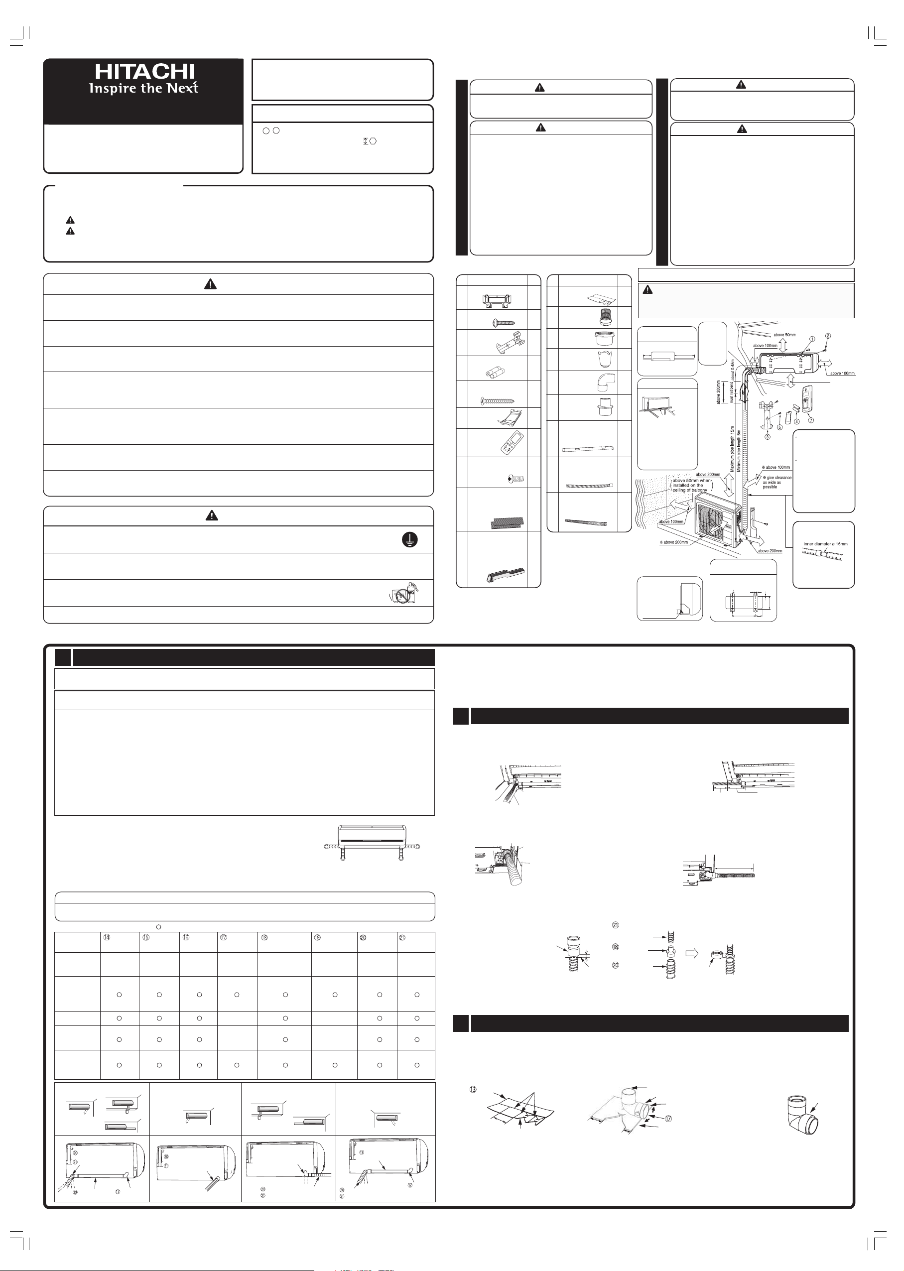
Figure showing the Installation of Indoor and Outdoor Unit.
1
In case the pipe length is more than 8m, add refrigerant R22 at 20
gram per every meter exceeds. However, pipe length shall not
exceed 15m.
1
The Length of Indoor
1
about
0.9m
1
• Do not alter the power cord.
1
Direction of Piping
1
There are 4 directions
allowed, namely, horizontally
perpendicular to the unit,
1
vertically down from right,
horizontally out from right and
horizontally out to left. Don't
form the piping downward at
the left of the unit.
1
1
Cut away shaded
portion, and
finish the edge of
the opening so
that there is no
burr.
• Do not expose the unit under direct sunshine or rain.
Besides, ventilation must be good and clear of
obstruction.
• The air blown out of the unit should not point directly to
animals or plants.
• The clearances of the unit from top, left, right and front
are specified in figure below. At least two of the above
sides must be open air.
• Be sure that the hot air blown out of the unit and noise
OUTDOOR UNIT
do not disturb the neighbourhood.
• Do not install at a location where there is flammable
gas, steam, oil and smoke.
• The location must be convenient for water drainage.
• Place the Outdoor unit and its connecting cord at least
1 m away from the antenna or signal line of television,
radio or telephone. This is to avoid noise interference.
CAUTION
Unit Power Cord
about 1.6m
Horizontally
perpendicular
to the unit
n
Dimension of Mounting
Stand of the Outdoor Unit
(unit : mm)
Mounting stand
20
WARNING
CAUTION
12
20
355
550
187
2,300mm or more
The difference in height
between the indoor and
outdoor unit should be
kept below 10m.
The connecting pipe,
no matter big or small,
should all be insulated
with insulation pipe and
then wrapped with
plastic tape.
(The insulator will
deteriorate if it is not
wrapped with tape).
The connection of
insulated drain hose.
Please use insulated
drain hose for the indoor
piping (commercial
product).
1
Fresh Air In Exhaust Hose Installation
The Fresh Air In Exhaust function is included in this model. Please follow the “Exhaust hose”
installation instructions when mounting.
Conditions when the fresh air in, exhaust should not be operated. (Please install only with the customer’s
consent).
• The fresh air In exhaust should not be operated under the following conditions:
(A) When the fresh air In exhaust hose cannot be vented directly outside the room (mounting work specified for the
embedded ducting).
(B) When there is a source of a questionable odor, smoke, or oily smoke in the vicinity of the opening of the fresh air In
exhaust hose, even if the mounting work directly vents the fresh air In exhaust hose outside the room.
• The fresh air in should not be operated (only exhaust can be operated) under the following conditions:
(C) When there is space to vent the fresh air In exhaust hose between the internal and external walls, which leads outside
the room, even if the mounting work cannot directly vent the fresh air In exhaust hose outside the room (conventional
construction methods).
• Please set the fresh air In exhaust Selection Switch according to the mounting configuration (refer to “Setting the Fresh Air
In Exhaust Selection Switch" on page 13).
In the case of (A) or (C) in the above, fresh air In exhaust can be operated if the fresh air In exhaust hose is vented outside
the room through a hole in the wall (refer to “End Treatment of the Fresh Air In Exhaust Hose” on page 14).
Dimension when Installing included Fittings
• ø 25 Fresh air in exhaust hose (A)
For directly backward piping or horizontally rear-out piping when the
hole in the wall is of ø 70mm or more.
• ø 20 Fresh air in exhaust hose (B)
For directly backward piping or horizontally rear-out piping when the
hole in the wall is of ø 65mm or more.
When the fresh air in exhaust hose of ø 25 and ø 20 are connected with
•
a reducing adapter, the dimension range will be as shown in the figure on the right.
within
0.6m
Dimensions when installing the fitting for
ø25 and ø20 fresh air in exhaust hose.
within
0.6m
within
0.5m
within
0.6m
UNUSED ACCESSORY
Unused accessories may become necessary in case of transfer of air conditioner. Request your customer to keep all
the unused accessories together with this installation manual and instruction manual.
Use of Accessories
Part Name
Remark
Backward
piping
Vertically down
from right
Horizontally
piping from right
Horizontally
rear-out piping
Vertically
down from left
Horizontally
piping from left
When the existing
hole in the wall is
out of alignment
in case of directly
backward piping
Backward
Horizontally
piping from right
Vertically down
piping
Fresh air in exhaust hose (A)
Fresh air in exhaust hose (B)
Air duct for rear
horizontal piping
Select ( ) depending on the installation condition.
Elbow for
right piping
Anti-insect
net adapter
use when
selecting ø20
fresh air in
exhaust hose
( )
( )
( )
( )
Hood
when fresh air
in exhaust
outlet cover
is not using.
Horizontally
rear-out piping
Fresh air in exhaust hose (A)
or
Fresh air in exhaust hose (B)
Anti-insect
net
from right
or
Elbow for
right piping
Reducing
adapter
use when connecting
ø25 and ø20 fresh
air in exhaust hose.
( )
( )
( )
( )
Vertically
down from left
Elbow for left piping
Fresh air in exhaust hose (A) or
Fresh air in exhaust hose (B)
Air duct for
rear horizontal
piping
Horizontally
piping from left
Fresh air
in exhaust
hose (A)
For the hole
in the wall of
70mm or more
( )
( )
( )
( )
When the existing hole in the
wall is out of alignment in case
of directly backward piping
Air duct for rear
horizontal piping
Fresh air in exhaust hose (A) or
Fresh air in exhaust hose (B)
Fresh air
in exhaust
hose (B)
For the hole
in the wall of
65mm or more
( )
( )
( )
( )
Elbow for
right piping
This model is supplied with two hoses. When a hole of ø70mm or more can be made on the wall, use the fresh air in exhaust
hose (A) of ø25. If the hole size is smaller than that, use of the fresh air in exhaust hose (B) of ø20 is recommended with a view
to easy installation. (However, there is no problem in using the fresh air in exhaust hose of ø25 if it can go though the hole of
below ø70mm.)
Make sure to decide which hose, i.e., either air in exhaust hose of ø25 or of ø20, only after obtaining customer’s
consent.
Please ensure that the entire length of the two way air exchange hose is within 3m.
2
Length Adjustment of the Fresh Air In Exhaust Hose
Backward piping • Directly backward piping by using
the existing hole in the wall
Target
Fresh air in exhaust
=++
hose
hose on the rear of
length
85mm
Thickness
of the wall
Fresh air in exhaust hose
on the rear of 85mm
Thickness
above
+
of the wall
230mm
above
230mm
Horizontally rear-out piping
Target
Distance from the fresh air in
hose
=
exhaust end connection to
length
the hole in the wall.
Extend the fresh air in exhaust hose
The fresh air in exhaust hose can be extended up to 1.2m by connecting the supplied fresh air in exhaust hose (A) and fresh air in
Distance from the fresh air in exhaust
end connection to the hole in the wall
Thickness
of the wall
Thickness
++
of the wall
above
+
230mm
above
230mm
Vertically down from right • Horizontally piping from right
Thickness
of the wall
Distance from the
indoor unit to the
hole in the wall
Fresh air in exhaust hose
on the rear of 180mm
above
++
230mm
Thickness
of the wall
above
230mm
Target
Fresh air in
=+ ++
hose
exhaust hose on
length
the rear of 180mm
Distance from the
indoor unit to the
hole in the wall
Vertically down from left • Horizontally piping from left
Target
Distance from the
hose
indoor unit to the
=++
length
hole in the wall
Thickness
of the wall
Distance from the
indoor unit to the
hole in the wall
above
230mm
Thickness
of the wall
++
above
230mm
exhaust hose (B) with the reducing adapter. When extending by connecting hoses of the same diameter, an additional optional
fresh air in exhaust hose is necessary.
When extending the hose, cut off the cuff on
the fresh air in exhaust hose to be connected
Cuff
Cut
Position
Fresh air in
exhaust hose (B)
Reducing
adapter
Fresh air in
exhaust hose (A)
Secure the fresh air in exhaust
hose to the reducing adapter by
wrapping vinyl tape around them
Vinyl tape
When desiring to extend the fresh air in exhaust hose more than 1.2m, an additional optional fresh air in exhaust hose needs to
be used. For connecting method, refer to the instructions supplied with the optional part.
Please shorten the length of the hose as much as possible to prevent the degradation of the fresh air in, exhaust operating
performance.
3
Connecting the Fresh Air in Exhaust Hose
Backward piping • Vertically down from right • Horizontally piping from right
Cut the hose insulation which is to be wrapped around the elbow for right piping along the perforation. Cover the elbow with
(1)
the insulation and secure them with vinyl tape.
(2)
Cut the hose insulation along the perforation. Cut it off according to the hose length.
(Insulation length: 200mm for directly backward piping / 180mm for vertically down from right and horizontally piping from
right + distance from the indoor unit to the hole in the wall)
Hose insulation
Cutting dimension
Insulation for right piping elbow
(3)
Securely connect the elbow for right piping, fresh air in exhaust hose (A) and fresh air in exhaust hose (B) to the air duct for
Perforation
Larger
dimension
Smaller
dimension
Connecting port side of the air duct for rear horizontal piping
Alignment line
The side of fresh air in exhaust end
connection
Elbow for right piping
Align the end face to the elbow line,
wrap and secure with vinyl tape
Secure with
vinyl tape
rear horizontal piping. Then, wrap the insulation which has been cut according to the above (2) around the fresh air in
exhaust hoses.
Cover the parts of the fresh air in exhaust hose which passes through the room with insulation sheet for hoses and wrap with
tape to ensure there are no spaces.
When horizontally piping is carried out for fresh air in exhaust hose, the split line of the hose insulation must come to the top.
Directly backward piping, vertically down from right and horizontally piping from right can be arranged by turning the fresh air in
exhaust hose by 90 degrees.
< IA233 : B >

CAUTION
• The draining hose in this indoor unit can be installed on the left or right. Indoor unit must be fixed horizontally or
slightly tilted towards the side of drain hose. Otherwise, condensed water may overflow the water container.
Ensure that the fresh air in exhaust hose which passes through the elbow the room is
•
CAUTION
covered with insulation sheet for hoses.
Dew may form on the elbow and fresh air in exhaust hose and there may be a possibility of
water droplets forming.
Air duct for rear horizontal piping
Make sure to bring the square
hole to the bottom side
Securely connect the fresh air in exhaust hose to the fresh air in exhaust
(4)
connecting port. The hole for rear horizontal piping should come to the
Elbow for right piping
Fresh air in exhaust hose (A) or
Fresh air in exhaust hose (B)
bottom side after the connection.
Square hole
Fresh air in exhaust end connection
Wrap the insulation for rear
horizontal piping without space
between insulation and hose, and
then secure them with tape (locally
procured)
Fresh air in exhaust
end connection
Horizontally rear-out piping
(1)
Cut off 100mm of the hose insulation to be wrapped around the fresh air in exhaust hose. Cover the fresh air in exhaust
hose (A) or (B) with the insulation, and secure them with vinyl tape.
Hose insulation
Securely connect the fresh air in exhaust hose to
(2)
the fresh air in exhaust connecting port.
Fresh air in exhaust hose (A) or
Fresh air in exhaust hose (B)
Fresh air in exhaust hose (A) or
Fresh air in exhaust hose (B)
Vertically down from left • Horizontally piping from left
Cut the hose insulation which is to be wrapped around the left piping elbow along the
(1)
perforation. Cover the elbow with the insulation and secure them with vinyl tape.
Cut the hose insulation along the perforation. Cut it off according to the hose length.
(2)
(Insulation length:
Securely connect the fresh air in exhaust hose (A) or (B) to the left piping elbow. Then, wrap
(3)
the insulation which has been cut according to the above (2) around the fresh air in exhaust
Distance from the indoor unit to the hole in the wall.)
hoses. Cover the fresh air in exhaust hose which runs indoor side with hose insulation and
Hose insulation
Insulation for left piping elbow
Perforation
wrap the tape without any space. When horizontally piping is carried out for fresh air in
exhaust hose, the split line of the hose insulation should come to the top.
Elbow for left piping
“LEFT” is indicated on the
opposite side of arrow
Smaller
dimension
(4)
Securely connect the fresh air in exhaust hose to the fresh
Larger
dimension
Align the end face to the elbow
line, wrap and secure with vinyl
tape.
Elbow for left piping
Fresh air in exhaust hose (A) or
Fresh air in exhaust hose (B)
air in exhaust connecting port.
(Vertically down from left and horizontally piping from left
can be arranged by turning the elbow for left piping by 90
degrees.)
When the Existing Hole in the Wall is Out of Alignment In
Case of Directly Backward Piping
(1)
Obtain dimension D by measuring the dimension of the
existing hole in the wall.
Remove the adapter at the tip of the air duct for rear
(2)
horizontal piping. Cut short the air duct for a length of
dimension D.
For insulation, cut it off into a length shorter than the air duct
main body by 23mm.
Attach the adapter to the tip of the air duct.
(3)
Cut the hose insulation which is to be wrapped around the
(4)
elbow for right piping along the perforation. Cover the elbow
with the insulation and secure them with vinyl tape.
Cut off 200mm of the hose insulation and wrap the cut
(5)
insulation around the fresh air in exhaust hose.
2 piping directions of vertically down from left and
horizontally piping from left are available by turning
the elbow for left piping by 90 degrees.
Existing hole
Indoor Unit
Proper hole
For the subsequent procedures, refer to “Directly
backward piping", "Vertically down from right",
"Horizontally piping from right”.
Fresh air in exhaust hose (A) or
Fresh air in exhaust hose (B)
Air duct main body
Adapter
Air duct for rear
horizontal piping
Insulation
1
Installation Of Mounting Plate, Wall Penetration And Protection Pipe
Direct mounting on the wall
•
Please use hidden beams in the wall to hold
the mounting plate.
When it is difficult to look for a stud, use an
•
item such as board anchor (sold on the open
market).
Board anchor
Level
Beam
Mounting
Plate
Stamp
Line
Weight Pipe hole
Drill hole for board anchor
•
While placing the mounting plate on the wall,
embed the board anchor in the wall.
Slide down the mounting plate and then fix
•
the mounting plate with the board anchor.
Visible outline of the indoor unit
INDOOR UNIT
Drain hose
Wall Penetration and Installation of Protection Pipe
• Drill a ø 65mm hole on wall which is slightly tilted
towards the outdoor side. Drill the wall at a small angle.
• Cut the protection pipe according to the wall thickness.
• Empty gap in the sleeve of protection pipe should be
completely sealed with putty to avoid dripping of rain
water into the room.
Wall
Indoor
Putty
Protection
Pipe
Outdoor
Putty
Sleeve of
Protection
Pipe
When mounting using crown molding and head jamb
•
Temporarily assemble the mounting plate and the vertical rail
according to the dimension H between the crown molding and
head jamb.
•
Using the crown molding and head jamb, temporarily attach
the top and the bottom of the vertical rail.
Clamp the mounting plate after making sure that it is level.
•
Vertical rail (optional)
Screw for mounting plate
Screw the mounting
(Screws in the illustration below are supplied
with the vertical rail.)
Vertical rail is an optional accessory
(Model : SP-BT-2)
plate at the positions
possibly near the upper
and lower hooks where
the indoor unit is hung.
Use 4 or more screws to
fix the mounting plater.
Better finishing with small gap between the
unit and the head jamb can be obtained by
aligning the mark “Vertical Rail 0 Position”
on the mounting plate to the scale “0” on the
vertical rail.
Mark on the
mounting plate
“Vertical Rail
0 Position”
•
Position of the hole to be made in the wall can
Head
jamb
Indoor unit
be decided by attaching the lower cover to the
mounting plate.
For right wall hole
For right
wall hole
Center of
the wall hole
Center of
the wall hole
.
When the hole in the wall is ø80mm, align the mark on
.
the lower side of the lower cover to the mark on the
Center of
the wall hole
For right wall hole
For right wall hole
Center
of the wall hole
Wall
hole
mounting plate. When the hole in the wall is ø65mm, align
the mark on the upper side of the lower cover to the
mark on the mounting plate.
CAUTION
•
Be sure that the wire is not in contact with any metal in
the wall. Please use the protection pipe as wire passing
through the hollow part of the wall so as to prevent the
possibility of damaged by mouse.
Unless it seals completely any air with high humidity
•
flows from outdoor and any dew may drop.
For right
wall hole
For right
wall hole
When installing between 0.90m pillars
Vertical rail (optional)
Wall
Indoor Unit
For the place where the pillar is projected from the wall surface, use the optional vertical rail
•
Pillar
for mounting between 0.90m pillars (model: SP-BT-3) or horizontal rail (model: SP-BY-1).
When installing using the existing hole in the wall
Existing hole in the wall
Indoor Unit
Auxiliary refrigerating pipe
of the indoor unit
2
Installation Of The Indoor Unit
When installing the unit using the existing hole in the wall but the indoor unit cannot be
•
moved due to a hole on the left side, form the auxiliary refrigerating pipe of the indoor unit as
shown in the illustration.
•
Form the pipe carefully to avoid crushing of the pipe.
•
For connection of the fresh air in exhaust hose, refer to “When the Existing Hole in the Wall
is Out of Alignment In Case of Directly Backward Piping” on page 5.
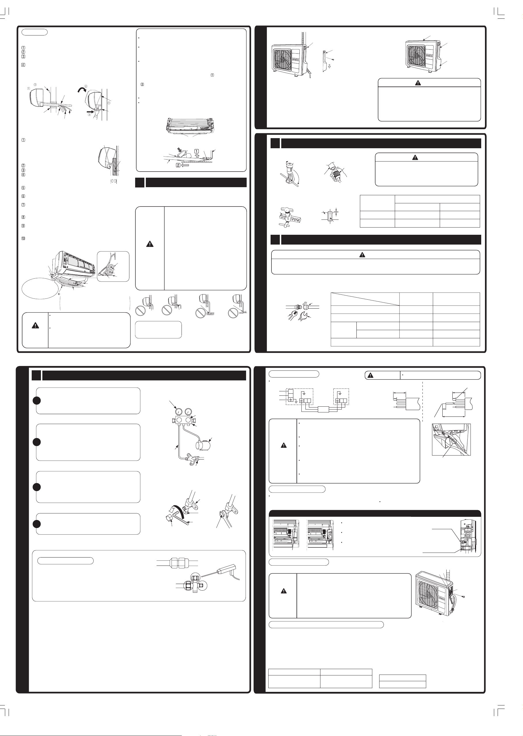
1. Preparation of Installation
Remove the Front Panel
• To remove front panel, please refer to page 15
“Removing and Attaching the Front Panel”.
• Make sure to use both hands to attach and remove
the front panel.
Remove the Top Grill
• To remove top grill, please refer to page
15 “Removing and Attaching the Top Grill”.
Remove the Lower Cover
• Pull at the 2 and 1 in the directions
as shown by arrows to remove the
lower cover.
• To attach the lower cover, attach 1
Removing
first and then attach 2 by rotating it
around the 1 as the fulcrum.
Wiring Connection
••Refer to page 12.
Cutting Lower Cover Bush
(Horizontal Downward Piping)
While installing the pipe from the right, left or bottom side,
•
use a knife to cut openings as shown in figure. Then
Attaching
smoothen the edges of openings with a file.
Use the groove on
•
the outer side when
installing the fresh
air in exhaust hose,
and use the groove
on the inner side
when not installing.
Groove on the outer side
Groove on the inner side
Bush
Bush
Changed of Drain Hose and Installation Procedures
(Horizontal Piping)
•
Exchange the location of drain hose and drain cap while
installing the pipe from the left side as shown on top right.
Remove the lower cover.
•
•
Do not carry out horizontal piping for drain hose.
< IA233 : B >
B Dimensions = (807-A) mm
Drain cap
Drain hose
Drain hose
Drain hose
Move the drain hose insulation to
take out the drain hose.
Insert drain cap up to the location
securely till the cap stops.
insulation sheet
Drain cap
CAUTION
Be sure to insert drain hose and
drain cap firmly. Insufficient insert
may result in water leakage.
It's easier to use pliers to pull out the drain cap.
Drain hose insertion cuff mark
Drain hose
insulation sheet
The rib at the indoor unit side
Drain hose
Securely push in the drain hose until the drain
hose cuff mark comes in contact with the rib
at the indoor unit side.
After inserting the drain hose, insert the drain
hose insulation sheet to the location securely.
Preparation of Refrigerating Pipe and Fresh Air In Exhaust Hose
Backward piping
Remove the auxiliary insulation material sheet which is attached to
the pipe insulation. (Keep the removed auxiliary insulation material
sheet because it will be reused after pipe connection.)
Referring to the mark on the rear side, form the pipe within the wall
hole range.
Place the starting
point of refrigerating
pipe bending within
the wall hole range.
Please bend at a
small radius to form an arc.
Pipe support
Finishing of pipe bending
must be within this range.
Auxiliary insulation sheet
If the starting point of
refrigerating pipe bending
is projected from the wall
hole range or if the bending
radius is too large, the
Wall hole
indoor unit may be lifted
range
from wall and this may
cause poor finishing.
(Mark detail)
Pipe support
Drain hole
Layout for the hole in the
wall of
directly backward piping
Center line
of wall hole
Fresh air in exhaust hose
ø
65 in case of
Auxiliary pipe
wall hole range
Bending of the
refrigerating pipe
must be within the
wall hole range.
Connect the fresh air in exhaust hose. (Refer to page 3
"Fresh Air In Exhaust Hose Installation").
Referring to the mark at the back, join the refrigerating pipe,
drain hose, fresh air in exhaust hose and connecting cord,
and then fix them temporarily with tape.
Mark detail
Layout for the hole in the
Pipe support
wall of ø65 in case of
directly backward piping
Drain
Drain
hose
hose
Center line
of wall hole
Auxiliary pipe
hole range
Bending of the
refrigerating pipe
must be within the
wall hole range.
Fresh air in exhaust hose
Pipe support
Join the refrigerating pipe, drain
hose, two way air exchange hose
and connecting cord, and then fix
them temporarily with tape.
Refrigerating
Connecting
pipe
cord
Drain hose
Please follow the same
layout as the mark.
Wrap the through-hole portion with tape.
Wrap with tape
Horizontally and Downward Piping from right
Remove the auxiliary insulation material sheet which is attached
to the pipe insulation. (Keep the removed auxiliary insulation
material sheet because it will be reused after pipe connection.)
Carry out refrigerating pipe forming.
In case of horizontally piping from
right, the fresh air in exhaust hose
runs below the pipe. Bend the pipe
so that it comes to the upper end
of the bottom cover bush hole, as
shown in the illustration on the
right.
Bottom cover
bush hole
Drain
hose
Layout of horizontally
piping from right
Refrigerating
pipe
Fresh air in
exhaust hose
Connect the fresh air in exhaust hose.
(Refer to page 3 "Fresh Air In Exhaust Hose Installation").
Referring to the mark at the back, join the refrigerating pipe,
drain hose, fresh air in exhaust hose and connecting cord,
and then fix them temporarily with tape.
Transform the
•
piping while holding
CAUTION
Installation after connection of refrigerating pipes
(Horizontally piping)
down the lower portion
of pipe-support by
hand.
Pipe
support
Transform
after bending
downward.
Remove the auxiliary insulation material sheet which is
attached to the pipe insulation.
Cut the heat insulation sheet refrigerating pipe aligning to the
insulation sheet of the pipe and fix them temporarily with tape.
Cover the pipe connection with the auxiliary insulation sheet,
which has been removed on earlier stage, with its split line on
the top. Wrap the tape without any space.
Connect the refrigerating pipe.
Tape must not be
over tightened.
Auxiliary insulation sheet
Refrigerating pipe
insulation sheet
Cut
Refrigerating
pipe
Refrigerating pipe
insulation sheet
Refrigerating
Fix temporarily
with tape
Form the refrigerating pipe according to the wall hole position.
Especially in case of horizontally backward piping, follow the
instruction below to carry out accurate forming.
<Forming of refrigerating pipe for horizontally
backward piping>
(1)
Referring to the mark at the back, start bending the
refrigerating piping within wall hole range.
Bend it with the
smallest radius.
wall
When forming, bend the refrigerating pipe with the
(2)
smallest radius as the layout of the mark.
Place the starting
point of refrigerating
pipe bending the
wall hole range.
< Mark detail >
Layout for the hole in the wall
of ø65 in case of horizontally
backward piping
wallwall
Center line
Center line
hole rangehole range
of wall hole
of wall hole
Fresh air in
Fresh air in
exhaust hose
exhaust hose
Refrigerating
pipe
Drain hoseDrain hose
Refrigerating
Refrigerating
pipe
pipe
Bend the refrigerating pipe to
follow the same layout as the mark.
Connect the fresh air in exhaust hose. (Refer to
page 3 "Fresh Air In Exhaust Hose Installation").
Form the connecting cord and refrigerating pipe and
put them in the space on the lower side of the rear
urface of the indoor unit. Fix them with the pipe
s
support.
Join refrigerating pipe, fresh air in exhaust hose,
connecting cord and drain hose temporarily with
tape and wrap the through-hole portion with tape.
Pipe support can be installed to
whichever side of the installation
points. However, it is recommended
to attach it on the right side viewing
from the rear.
Connecting the Refrigerating Pipe at the Back of the
Indoor Unit
•
Form and set the refrigerating pipe and the connecting
cord.
Please bend at a small
radious to form an arc.
pipe
(Pipe can be bent with a
small radius without being
crushed if polyester core is
used.)
Pipe support
The end of the refrigerating pipes are
at locations marked with “ ” symbol.
Insert polyester core (commercial
product) into the pipe.
•
When using a polyester core,
make sure to insert it only after
CAUTION
flaring is carried out to avoid
cutting dust from getting inside.
If the starting point
of refrigerating pipe
bending is projected
from the wall hole
range or if the
bending radius is
too large, the indoor
unit may be lifted
from wall and this
may cause
poor finishing.
Pipe support
Fresh air in
exhaust hose
Wrap with tape
below
5 mm
Installation
Connecting the Refrigerating Pipe other than at the back
of the Indoor Unit
Insert the pipe through the wall hole.
The upper part of the Indoor unit is hung on the hanger.
The projection at the lower part of the Indoor unit is
hooked onto the hanger.
After the refrigerating pipe is connected,
connection with the auxiliary insulation sheet, which has
been removed on earlier stage, with its split line on the top.
Wrap the tape without any space.
Mounting Plate
Protection
Pipe
Refrigerating
Pipe
Drain
hose
Fresh air in
exhaust hose
F connecting
cord
cover the pipe
Mounting
Plate
Projection of
the indoor unit
Connecting the Refrigerating Pipe at the back of the
Indoor Unit
Remove the auxiliary insulation material
sheet which is attached to the pipe
insulation. (Keep the removed auxiliary
insulation material sheet because it will
be reused after pipe connection.)
Carry out refrigerating pipe forming.
Connect fresh air in exhaust hose.
Hang the indoor unit on the mounting plate.
Place the temporary stand under the right
rear surface of the indoor unit to lift the lower
side of the unit by approximately 15cm.
Connect the refrigerating pipe. (Refer to “Pipe
Connection” on Page 10)
Wrap the pipe connection with tape so that there is no
gap between heat insulation sheet.
Insert the drain hose and fresh air in exhaust hose into
the wall hole. Especially in case of horizontally backward
piping, insert the hose following the explanation below.
Connect the connecting cord. (Refer to “Connection of
Power Cord” on Page 12)
Form connecting cord and refrigerating pipe and put them
in the space on the lower side of the rear surface of the
indoor unit. Fix them with the pipe support.
Remove the temporary stand under the indoor unit and fit
the lower part of the indoor unit in the fixing tab on the
mounting plate.
Fresh air in
exhaust hose
Protection pipe
Drain hose
Pull this to the front
during the connection
of refrigerating
pipe to ease task.
CAUTION
Do not over tighten vinyl tape on pipe heat
insulation sheet. Do not over tighten to avoid loss
of heat insulating effect and dew condensation.
Pull the lower part of the indoor unit towards
you and confirm that the tab of the indoor
unit is fit in the installation plate. If the tab is
not fitted in securely, vibration of the indoor
unit becomes larger.
F connecting cord
Pipe support
Pipe support can be installed to whichever side
of the installation points. However, it is
recommended to attach it on the left side
viewing from the front of the indoor unit.
Projection of the
indoor unit
F connecting cord
Heat insulation pipe
Connecting part
Fixing
tab
Temporary
stand
Approx. 15mm
Heat
insulation
pipe
Refrigerating
pipe
Tape
How to Remove Indoor Unit
Remove the left and right lower cover. (Refer to page 7 on
how to remove the lower cover)
Push the [PUSH] sections at the bottom of the indoor unit
from the outside, the claws are released from the
mounting plate. (2 places on the left and right)
If the bottom of the indoor unit cannot be pushed due to
the member such as horizontal rail above the head jamb,
remove the front cover and insert a screwdriver into the
hole for removal of indoor unit. Then, push the claws
upwards while holding down the upper part of the hole and
pull the indoor unit towards you. When horizontal piping
is used, be careful not to damage the pipe and F cable
with the tip of the screwdriver during this operation.
Please refer to page 16 on how to remove the front cover.
If the pipe support is installed on the left side viewing from
the front of the indoor unit, remove the lower side of the
pipe support.
Hole for removal
Hold with a hand
Hole for removal
Screwdriver
Claw
Mounting plate
• Please mount the outdoor unit on stable ground to
prevent vibration and increase of noise level.
• Decide the location for piping after sorting out the
OUTDOOR UNIT
different types of pipe available.
• Open the side plate by unscrewing the screws as
shown on the right side.
1 Preparation of Pipe
• Use a pipe cutter to cut the copper pipe.
3 Drainage Check
After the indoor unit is installed, Please ensure the smooth
flow of condensed water of the Indoor unit during
installation. (Careless work may result in water leakage.)
•
During drainage work, install the drain
pipe to ensure smooth drainage. Make
sure to carry out drainage check.
(Careless work may result in water
)
leakage.
Make sure that there is no problem as
•
shown below.
Such problems may cause clogged drain
CAUTION
and could result in water leakage.
Drain hose must be at a slope of at
•
least 1/25.
When inserting the drain hose into the
•
drain pipe for embedded piping, etc.,
do not cut the drain hose in the middle.
This may lead to poorer heat insulating
performance of the drain hose and could
result in water leakage.
Condensed
water pond
Bending
upwards
Condensed
water pond
Be sure that the drain
hose is not loosely
connected.
Ditch
When the ventilating fan is used in
an airtight house, a gurgling sound
may be heard from around the
drain pipe.
In such a case, use the drain tank
(service part RAS-2810KX 500).
• Before flaring, please put on the flare nut.
Please use exclusive tool.
•
Die
2 Pipe Connection
• In case of removing flare nut of an indoor unit, first remove a nut of small diameter side, or a seal cap of big
• Please be careful when bending the copper pipe.
• Screw in manually while adjusting the centre. After that, use a torque wrench to tighten the connection.
INSTALLATION OF REFRIGERATING PIPES
Wrench
Please face this side (suction side)
of the unit to the wall.
Please remove side cover
when connecting the piping
and connecting cord.
Pull
downward
Please make sure to remove all spacers inside the
unit.
• Open the Top, Back and Side cover of the unit.
• Pull out the spacers inside.
(Spacers are only for transportation purpose.) If not
remove, vibration and noise will occur.
CAUTION
•
Jagged edge will cause leakage.
•
Point the side to be trimmed downwards during
trimming to prevent copper chips from entering the
pipe.
Imperial Flaring Tool
0.8 - 1.5 mm
1.0 - 2.0 mm
Copper pipe
Die
Trimming tool
A
Copper pipe
Outer
Diameter (mm)
6.35
15.88
CAUTION
diameter side will fly out. Prevent water from entering into the piping when working.
Flare nut
Torque
Small diameter side
Large diameter side
Valve head
cap
Small diameter side
Large diameter side
Valve core cap
Outer diameter
of pipe
6.35
9.52
6.35
9.52
Top cover
Back cover
Side cover
CAUTION
A (mm)
Rigid Flaring Tool
0 - 0.5 mm
0 - 1.0 mm
Torque N • m
(kgf • cm)
13.7 – 18.6 (140 – 190)
49 – 58.5 (500 – 600)
19.0 – 21.0 (194 – 214)
29.0 – 31.0 (295 – 318)
9.0 (92)
1 Remove of Air from the Pipe and Gas Leakage Inspection
As shown in figure on the right, remove the cap
of valve head and valve core and then connect
1
them to the vacuum pump and manifold valve.
Fully tighten the “Hi” shuttle of the manifold valve
and completely unscrew the “Lo” shuttle. Run
the vacuum pump for about 10-15 minutes, then
2
completely tighten the “Lo” shuttle and switch off
the vacuum pump.
Completely unscrew the spindle of the service
valve (at 2 places) in anti-clockwise direction to
3
allow the flow of coolant (using Hexagonal
Wrench key).
Remove the Charge hose and tighten the cap of
4
valve head. The task is then completed.
AIR REMOVAL
Gas Leakage Inspection
Please use gas leakage detector to check if leakage
occurs at the connection of Flare nut as shown on the
right.
If gas leakage occurs, further tighten the connection to
stop leakage.
When the meter reaches –101KPa (–76cmHg)
during pumping, fully tighten the shuttle.
Meter showing pressure
Lo
Hi
Manifold valve
Vacuum pump
Charge
hose
When pumping starts, slightly loosen
the flare nut to check of air sucked in.
Then tighten the flare nut.
The body of
service valve
Cap of
valve core
Hexagonal
Wrench Key
Cap of valve head
Cap of valve head
Procedures of Wiring
In case the power is supplied from indoor unit.
Line Cord
WARNING
Indoor Unit
L
N
BA BA
Connecting Cord
Outdoor Unit
ø2.0
The naked part of the wire core should be 10mm and fix it to the
terminal tightly. Then try to pull the individual wire to check if the
contact is tight. Improper insertion may burn the terminal.
Be sure to use only power cables approved from the authorities
in your country.
Please refer to the installation manual for wire connection to the
terminals of the units. The cabling must meet the standards of
electrical installation.
There is an AC voltage of 220-240V between the L and N
terminals. Therefore, before servicing, be sure to remove the
plug from the AC outlet or switch off the main switch.
Do not make any conection in the middle of the connecting
cable. It may cause the wire overheating, emit smoke and fire.
Wiring of the Indoor Unit
For wire connection of the indoor unit, you need to
remove front panel and electrical cover.
Method to remove electrical cover
Method to remove electrical cover
Remove the screw and electrical
cover.
Insert the connecting cord (A, B) from
the bottom of unit.
Fix the wire to terminal wires firmly as
Screw Electrical cover
shown in figure at right side.
Wiring of the Outdoor Unit
•
Please remove the side cover for wire connection.
CONNECTION OF POWER CORD
WARNING
• If you cannot attach the side cover due to the connecting
cord, press the conencting cord in direction to the front
panel to fix it.
• Be sure that the hooks of the side cover is fixed
certainly. Otherwise water leakage may occur and this
causes short circuit or faults.
• The connecting cord should not touch to service valve
and pipes. (It becomes high temperature in heating
operation.)
WARNING
Indoor
Unit
THIS APPLIANCE MUST BE EARTHED.
Power line
30mm
15mm
Outdoor
Unit
10mm
10mm
GRN + YEL
Connecting cord for outdoor thermistor
need to fix with indoor power cord by
using binder.
Purpose is to avoid this connecting
cord from pulled out when pulling is
given.
25mm
35mm
M
-
N
7
2
2
C
E
I
Strip wires
S
.
U
A
H
C
R
U
E
K
-
A
M
E
K
5
.
1
Method to remove the front panel
Refer to "Removing and Attaching the Front Panel"
on page 15.
Connect the
earth cord
After removing the
screw and band,
put the connecting
cord and fix the
band with screw.
B
A
Earth terminal
G
3
< IA233 : B >
Checking for the electric source and the voltage range
• Before installation, the power source must be checked
and necessary wiring work must be completed. To
make the proper wiring capacity, use the wire
gauges list below for the lead-in from a pole
transformer and for the wiring from a switch board of
fuse box to the outlet in consideration of the locked
rotor current.
IMPORTANT
Cable length
up to 15m
up to 25m
Wire cross-section
2
2.5mm
2
4.0mm
•
Investigate the power supply capacity and other
electrical conditions at the installation location.
Depending on the model of room air conditioner to
be installed, request the customer to make
arrangements for the necessary electrical work
etc.The electrical work includes the wiring work up
the outlet. In localities where electrical condition sare
poor, use of a voltage regulation is recommended.
IMPORTANT
Fuse Capacity
20A time delay fuse
 Loading...