

Page 1
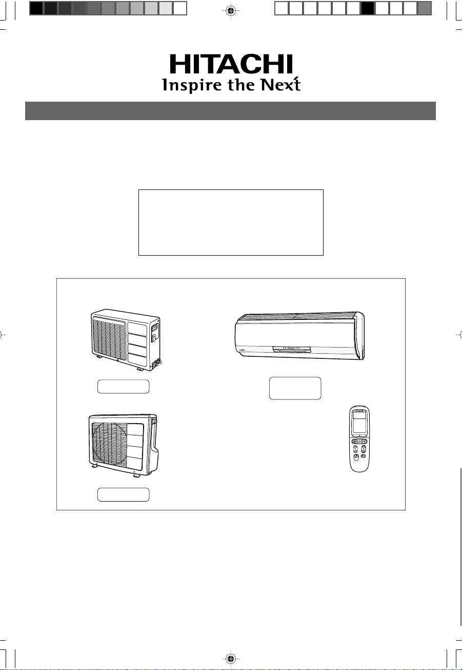
SPLIT TYPE
INDOOR UNIT/OUTDOOR UNIT
MODEL
RAS-10EX9K/RAC-10EX9
RAS-13EX9K/RAC-13EX9
OUTDOOR UNIT
RAC-10EX9
RAC-13EX9
INDOOR UNIT
RAS-10EX9K
RAS-13EX9K
Instruction manual Page 1~36
To obtain the best performance and ensure years of trouble free use, please read this instruction manual
completely.
!" 37~72
!"#$%&'()*+,-./%&01%23456789:;<
RAS/RAC-10/13EX9K (Cover) 27/4/05, 3:11 PM36
¶´ƒ
Page 2
SAFETY PRECAUTION
●
Please read the “Safety Precaution” carefully before operating the unit to ensure correct usage of the unit.
●
Pay special attention to signs of “ Warning” and “ Caution”. The “Warning” section contains matters which,
if not observed strictly, may cause death or serious injury. The “Caution” section contains matters which may
result in serious consequences if not observed properly. Please observe all instructions strictly to ensure safety.
●
The sign indicate the following meanings.
!
!
Make sure to connect earth line.
Indicates the instructions that must be followed.
●
Please keep this manual after reading.
PRECAUTIONS DURING INSTALLATION
●
Do not reconstruct the unit.
Water leakage, fault, short circuit or fire may occur if you reconstruct
the unit by yourself.
●
Please ask your sales agent or qualified technician for the installation
!
WARNING
!
CAUTION
of your unit. Water leakage, short circuit or fire may occur if you install
the unit by yourself.
●
Please use earth line.
Do not place the earth line near water or gas pipes, lightning-conductor,
or the earth line of telephone. Improper installation of earth line may
cause electric shock.
●
A circuit breaker should be installed depending on the mounting site of
the unit. Without a circuit breaker, the danger of electric shock exists.
●
Do not install near location where there is flammable gas. The outdoor
unit may catch fire if flammable gas leaks around it.
●
Please ensure smooth flow of water when installing the drain hose.
The sign in the figure indicates prohibition.
W
A
R
N
N
G
!
W
A
R
N
N
G
PRECAUTIONS DURING SHIFTING OR MAINTENANCE
●
Should abnormal situation arises (like burning smell), please stop operating the unit
!
I
and turn off the circuit breaker. Contact your agent. Fault, short circuit or fire may
occur if you continue to operate the unit under abnormal situation.
●
Please contact your agent for maintenance. Improper self maintenance may cause
electric shock and fire.
●
Please contact your agent if you need to remove and reinstall the unit. Electric
shock or fire may occur if you remove and reinstall the unit yourself improperly.
PRECAUTIONS DURING OPERATION
●
Avoid an extended period of direct air flow for your health.
●
Do not put objects like thin rods into the panel of blower and suction side
because the high-speed fan inside may cause danger.
●
Do not use any conductor as fuse wire, this could cause fatal accident.
I
●
This unit has UV LED which emits ultra violet light.
AVOID DIRECT EYE EXPOSURE.
●
During thunder storm, disconnect and turn off the circuit breaker.
!
– 2 –
Page 3
PRECAUTIONS DURING OPERATION
●
The product shall be operated under the manufacturer specification and
not for any other intended use.
●
Do not attempt to operate the unit with wet hands, this could cause fatal
accident.
●
When operating the unit with burning equipments, regularly ventilate the
room to avoid oxygen insufficiency.
●
Do not direct the cool air coming out from the air-conditioner panel to face
household heating apparatus as this may affect the working of apparatus
such as the electric kettle, oven etc.
●
Please ensure that outdoor mounting frame is always stable, firm and
without defect. If not, the outdoor unit may collapse and cause danger.
●
Do not splash or direct water to the body of the unit when cleaning it as this
may cause short circuit.
ENGLISH
●
!
C
A
Do not use any aerosol or hair sprays near the indoor unit. This chemical
can adhere on heat exchanger fin and blocked the evaporation water flow
to drain pan. The water will drop on tangential fan and cause water splashing
out from indoor unit.
U
T
I
O
●
Please switch off the unit and turn off the circuit breaker during cleaning, the
high-speed fan inside the unit may cause danger.
N
●
Turn off the circuit breaker if the unit is not to be operated for a long period.
●
Do not climb on the outdoor unit or put objects on it.
●
Do not put water container (like vase) on the indoor unit to avoid water
dripping into the unit. Dripping water will damage the insulator inside the unit
and causes short-circuit.
●
Do not place plants directly under the air flow as it is bad for the plants.
●
When operating the unit with the door and windows opened, (the room humidity is always above
80%) and with the air deflector facing down or moving automatically for a long period of time,
water will condense on the air deflector and drips down occasionally. This will wet your furniture.
Therefore, do not operate under such condition for a long time.
●
If the amount of heat in the room is above the cooling or heating capability of the unit (for
example: more people entering the room, using heating equipments and etc.), the preset room
temperature cannot be achieved.
– 3 –
Page 4
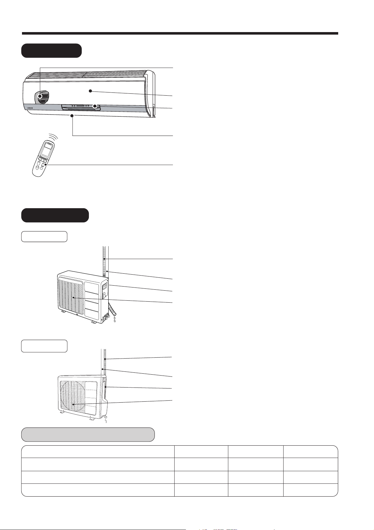
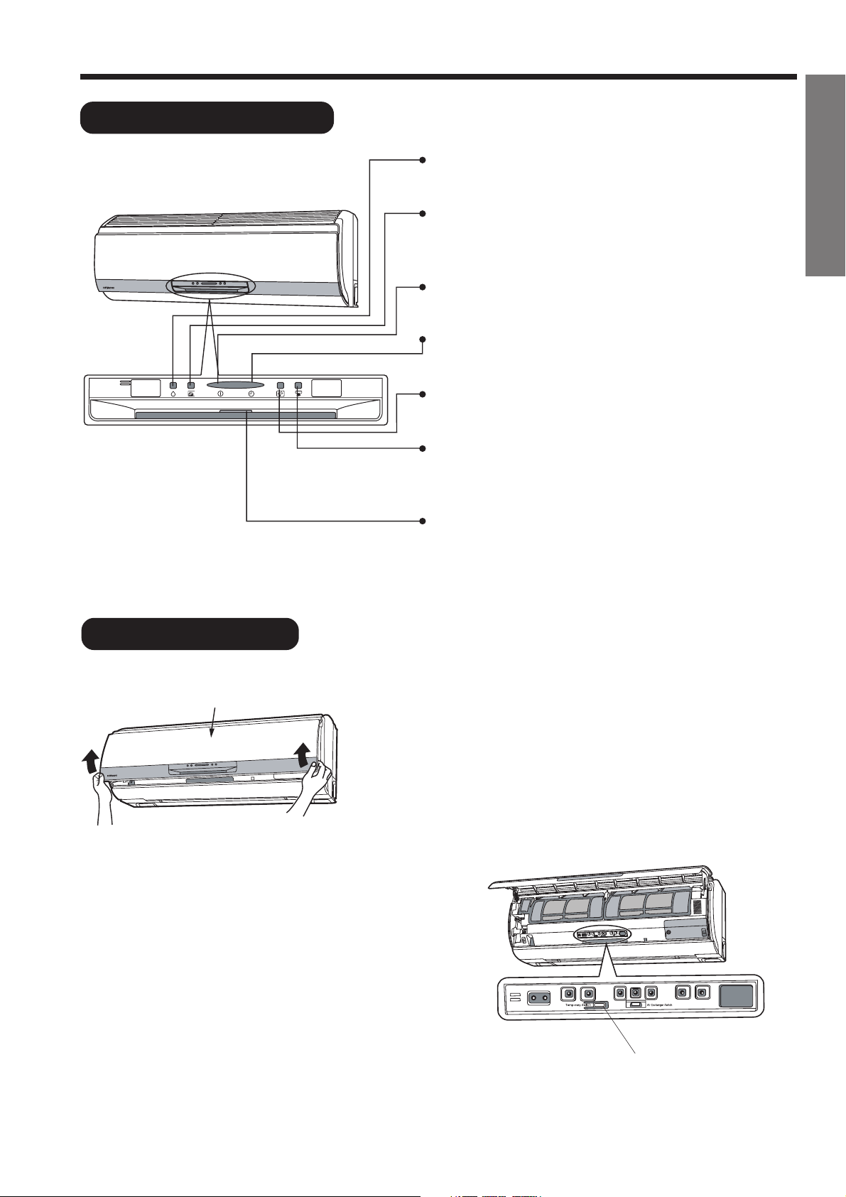
NAMES AND FUNCTIONS OF EACH PART
INDOOR UNIT
AIR FILTER
To prevent dust from coming into the indoor unit.
(Refer page 29)
FRONT PANEL (AIR INLET)
INDOOR UNIT INDICATORS
Light indicator showing the operating condition.
(Refer page 5)
OUTDOOR UNIT
RAC-10EX9
HORIZONTAL DEFLECTOR
DEFLECTOR (AIR OUTLET)
(Refer page 21)
REMOTE CONTROL
Send out operation signal to the indoor unit. So as to
operate the whole unit.
(Refer page 7)
DRAIN PIPE
Condensed water drain to outside.
CONNECTING CORD
AIR INLET (BACK)
AIR OUTLET
●
VERTICAL
RAC-13EX9
MODEL NAME AND DIMENSIONS
RAS-10EX9K / 13EX9K
RAC-10EX9
RAC-13EX9
DRAIN PIPE
Condensed water drain to outside.
CONNECTING CORD
AIR INLET (BACK)
AIR OUTLET
WIDTH (mm)MODEL
840
700
750
– 4 –
HEIGHT (mm)
298
570
570
DEPTH (mm)
248
210
280
Page 5
INDOOR UNIT INDICATORS
DEHUMIDIFY LAMP
This lamp lights during dehumidifying.
AIR PURIFIER LAMP
This lamp lights when the device is configured to air
purifier.
OPERATION LAMP
This lamp lights during operation.
TIMER LAMP
This lamp lights when the timer is working.
AIR EXHAUST LAMP
This lamp lights when the exhaust is operating.
SUPER COOLING LAMP
This lamp lights when the device is configured to super
cooling.
AIR EXCHANGER LAMP
This lamp lights when the ventilation is operating.
ENGLISH
TEMPORARY SWITCH
Front Panel
Use this switch to start and stop when the remote
controller does not work.
● By setting the temporary switch, the operation is
done in previously set operation mode.
● When the operation is done using the temporary
switch after the power source is turned off and
turn on again, the operation is done in automatic
mode.
● Hold both sides of the front panel and lift up.
● When the works are done, follow the opposite direction
to close it. (When the “click” sound is heard, it means
the panel is closed properly.)
– 5 –
Temporary Switch
Page 6
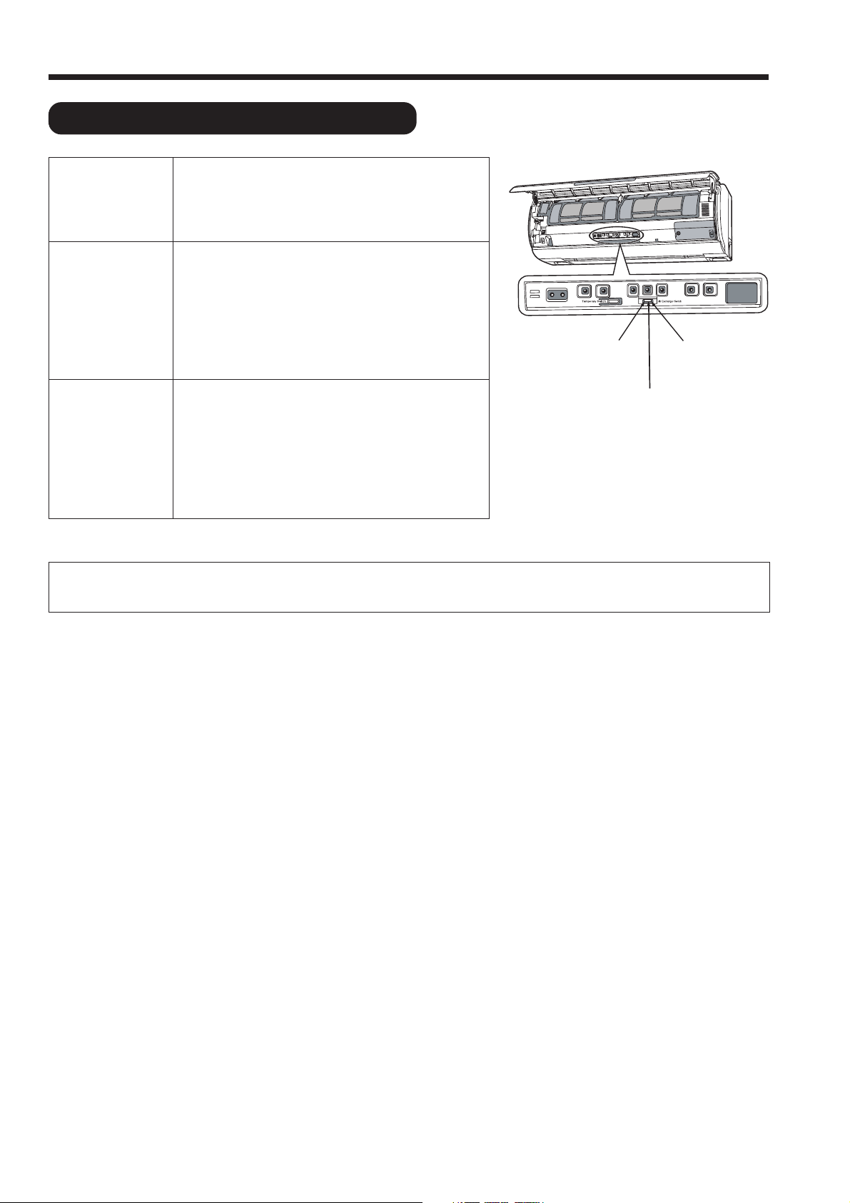
NAMES AND FUNCTIONS OF EACH PART
AIR EXCHANGER SELECTION SWITCH
OPERATE
AIR
EXCHANGER
ONLY EXHAUST
OPERATE
AIR
EXCHANGER
No matter in which mode the air exchanger selection switch is selected, twin air flow operation and air purifier
operation can be functioned.
Select the switch when using air-exchanger
operation. In normal condition, please use this
mode.
This mode is set initially from manufacturer.
Select the switch when there is no intake
operation.
This mode is operational when the intake and
exhaust hose cannot directly connect to outdoor.
The hose outlet is located in a space between
inner wall and outer wall, and these space is
connected to outdoor.
Select the switch when air exchanger is
prohibited. When the intake and exhaust hose
cannot connect directly to the outdoor
(installation work specified for the embedded
ducting), or even the hose can be connected to
the outdoor but there is a source of odor, oil or
smoke near the exit of intake and exhaust hose.
Prohibit Air
Exchanger
Only Exhaust
Operate Air
Exchanger
– 6 –
Page 7
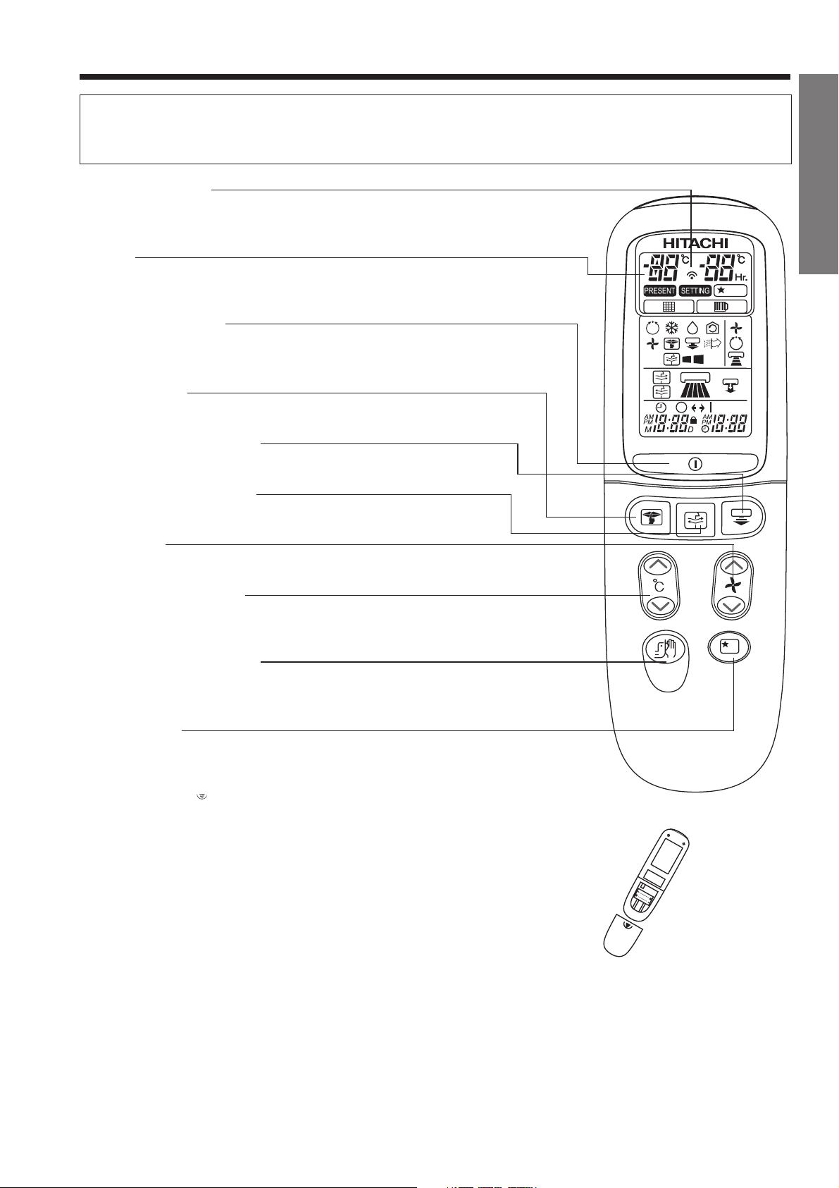
NAMES AND FUNCTIONS OF REMOTE CONTROL
REMOTE CONTROL : This controls the operation of the indoor unit. The range of control is about 7
meters. If indoor lighting is controlled electronically, the range of control may be shorter.
Before fixing it, make sure the indoor unit can be controlled from the remote controller.
Transmission Sign
Point this window toward the indoor unit when controlling it.
The transmission sign blinks when a signal is sent.
Display
This indicates the room temperature selected, current time,
timer status, function and intensity of circulation selected.
START/STOP Button
Press this button to start operation. Press it again to stop
operation.
SILENT Button
Press this button to start silent mode.
SUPER COOLING Button
Press this button to start super cooling mode.
ENGLISH
AIR EXCHANGER Button
Press this button to start ventilation mode.
FAN Button
Use this button to increase and decrease fan speed.
TEMPERATURE Button
Use this button to raise or lower the temperature setting.
(Keep pressing and the value will change more quickly.)
TEMPERATURE Indicator
Use this button to indicate temperature of indoor and
outdoor.
SLEEP Button
Use this button to set the sleep timer.
BACK
Press the arrow “ ” on the back cover and push or pull
to the indicated direction, to open or close the battery cover.
– 7 –
Page 8
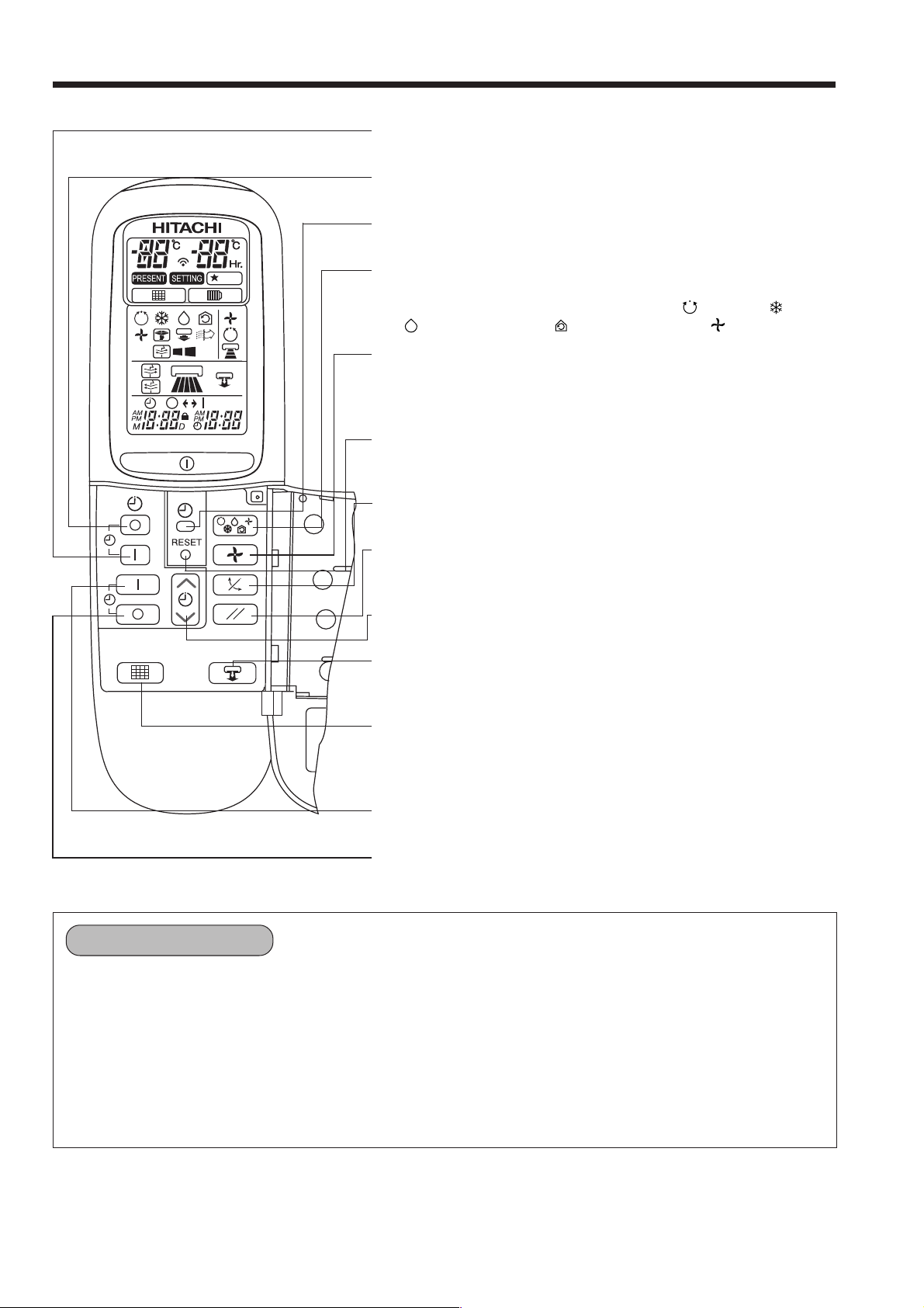
NAMES AND FUNCTIONS OF REMOTE CONTROL
ON-TIMER Button
Select the turn ON time.
OFF-TIMER Button
Select the turn OFF time.
TIME Button
Use this button to set and check the time and date.
FUNCTION Selector
Use this button to select the operating mode. Every time you
press this button, the mode will change from AUTO → COOL
→ DEHUMIDIFY → CIRCULATION → FAN cyclically.
FAN SPEED Selector
This determines the fan speed. Every time you press this button,
the intensity of circulation will change from AUTO → HI → MED
→ LOW cyclically.
RESET Button
Press this button after the batteries are replaced or when some
irregular operation is found.
AUTO SWING Button
Controls the angle of the horizontal air deflector.
PARALLEL WING Button
Use this button to control angle of the vertical air deflector to
parallel.
TIMER Control
Use these buttons to set the timer.
TWIN AIR FLOW Button
Use this button to allow two different air flows circulate in every
corner of room efficiently.
FILTER Button
Press this button when you have cleaned the filter. About 200
hour after this, the FILTER lamp will light to indicate that it is the
time to clean the filter.
RESERVE Button
Time setting reservation.
CANCEL Button
Cancel time reservation.
Precautions for Use
Do not put the remote controller in the following places.
Under direct sunlight.
In the vicinity of a heater.
Handle the remote controller carefully. Do not drop it on the floor, and protect it from water.
Once the outdoor unit stops, it will not restart for about 3 minutes (unless you turn the power switch off
and on or unplug the power cord and plug it in again). This is to protect the device and does not
indicate a failure.
If you press the FUNCTION selector button during operation, the device may stop for about 3 minutes for
protection.
– 8 –
Page 9
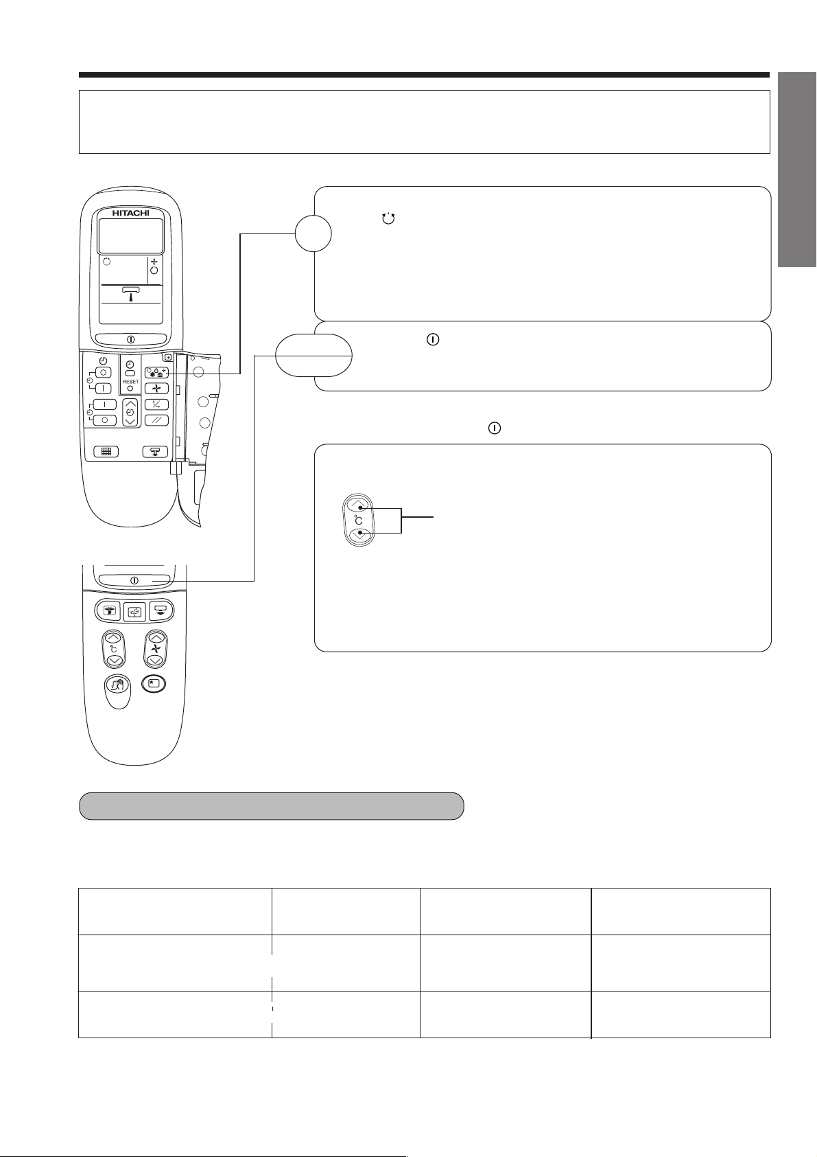
AUTOMATIC OPERATION
The device will automatically determine the mode of operation COOL, or Dehumidify, depending on the
initial room temperature. The selected mode of operation will not change when the room temperature
varies.
Press the FUNCTION selector so that the display indicates
the (AUTO) mode of operation.
1
● When AUTO has been selected, the device will
automatically determine the mode of operation COOL or
Dehumidify, depending on the initial room temperature
and outdoor temperature.
START
STOP
■ As the settings are stored in memory in the remote controller, you
Press the
Operation starts with a beep.
Press the button again to stop operation.
only have to press the
You can raise or lower the temperature setting as necessary by
maximum of 3°C.
● The preset temperature and the actual room temperature may
vary somewhat depending on conditions.
● The display does not indicate the preset temperature in the
AUTO mode. If you change the setting, the indoor unit will
produce a beep.
(START/STOP) button.
(START/STOP) button next time.
Press the temperature button and the
temperature setting will change by 1°C each
time.
ENGLISH
■ CONDITION OF AUTOMATIC OPERATION
● The selected mode of operation will not change during the operation even though the room temperature
change.
INITIAL ROOM
TEMPERATURE (APPROX.)
Over 27°C COOL
16~27°C
FUNCTION
-
-
DEHUMIDIFY
– 9 –
TEMPERATURE
SETTING
27°C
Slightly lower than the
room temperature
FAN SPEED
HIGH at start, LOW after
the preset temperature is
reached.
LOW
Page 10
C
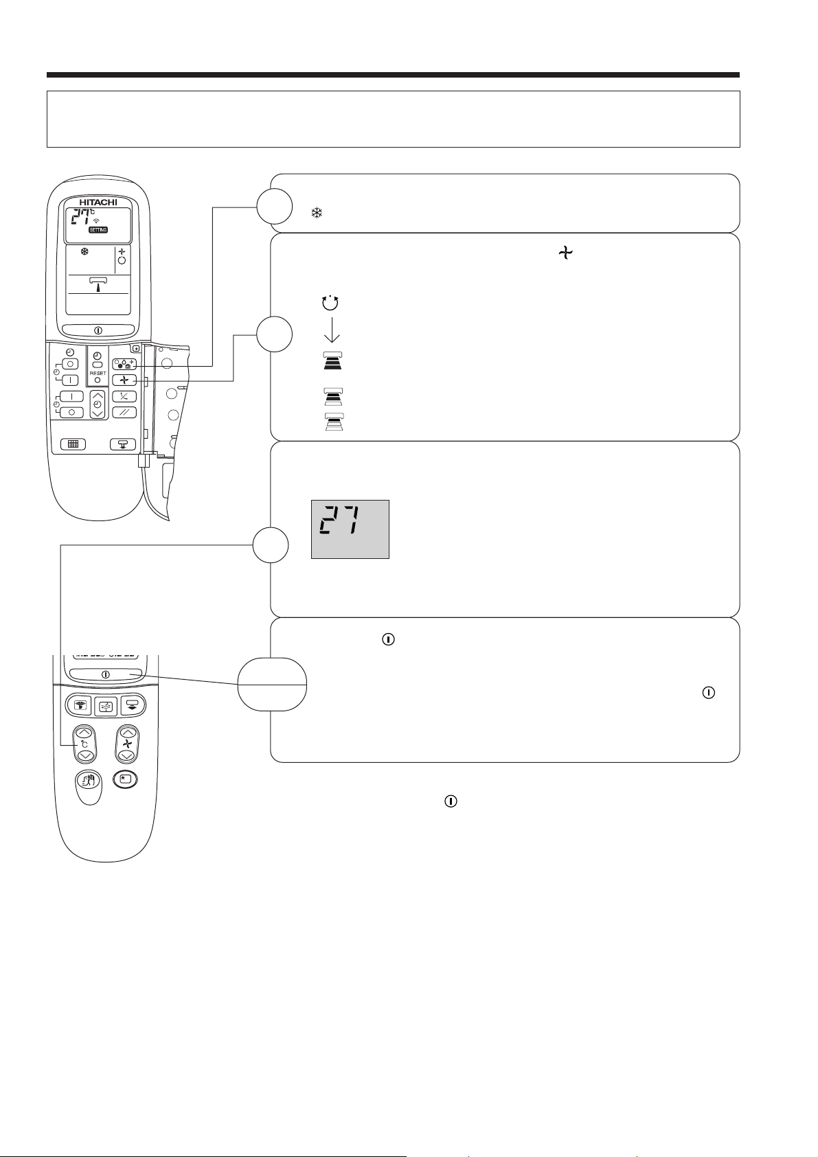
COOLING OPERATION
Use the device for cooling when the outdoor temperature is 21-42°C.
If humidity is very high (over 80%) indoors, some dew may form on the air outlet grille of the indoor unit.
Press the FUNCTION selector so that the display indicates
1
(COOL).
2
3
START
STOP
Set the desired FAN SPEED with the
(the display indicates the setting).
(AUTO): The FAN SPEED is HI at first and varies to
MED automatically when the preset temperature
has been reached.
(HI) : Economical as the room will become cool
quickly.
(MED) : Fan speed slow.
(LOW) : Fan speed slower.
Set the desired room temperature with the TEMPERATURE
button (the display indicates the setting).
The range of 25-28°C is recommended as the
˚
The temperature setting and the actual room temperature may
vary somewhat depending on conditions.
Press the
with a beep. Press the button again to stop operation. The
cooling function does not start if the temperature setting is
higher than the current room temperature (even though the
(OPERATION) lamp lights). The cooling function will start as
soon as you set the temperature below the current room
temperature.
room temperature for cooling.
If the temperature setting is 27°C, the room
temperature will be controlled at around 27°C.
(START/STOP) button. Cooling operation starts
(FAN SPEED) button
■ As the settings are stored in memory in the remote controller, you
only have to press the
– 10 –
(START/STOP) button next time.
Page 11
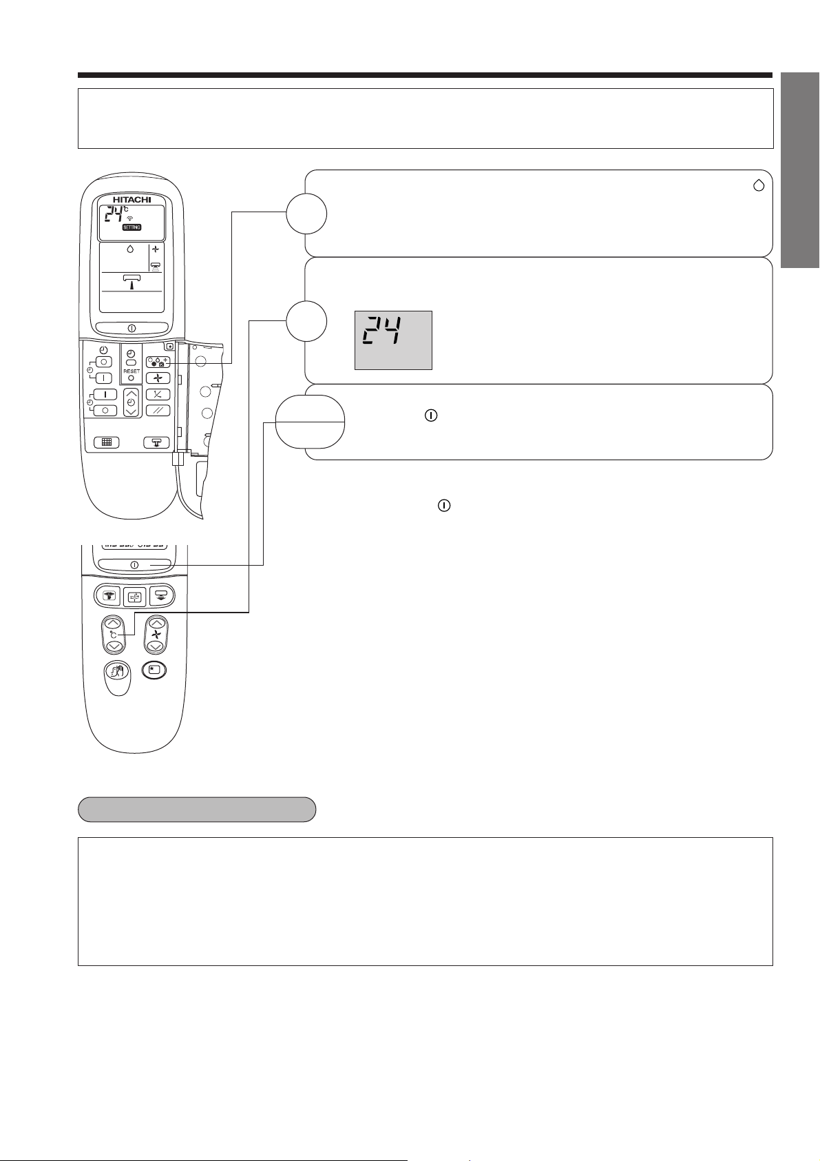
DEHUMIDIFYING OPERATION
C
Use the device for dehumidifying when the room temperature is over 16°C.
When it is under 15°C, the dehumidifying function will not work.
Press the FUNCTION selector so that the display indicates
(DEHUMIDIFY).
1
The FAN SPEED is set at LOW automatically.
The FAN SPEED button does not work.
Set the desired room temperature with the TEMPERATURE
button (the display indicates the setting).
ENGLISH
2
˚
START
STOP
■ As the settings are stored in memory in the remote controller, you only
Press the (START/STOP) button. Dehumidifying operation
starts with a beep. Press the button again to stop operation.
have to press the
The range of 20-26˚C is recommended as the
room temperature for dehumidifying.
(START/STOP) button next time.
■ Dehumidifying Function
When the room temperature is higher than the temperature setting: The device will dehumidify the room,
reducing the room temperature to the preset level.
When the room temperature is lower than the temperature setting: Dehumidifying will be performed at the
temperature setting slightly lower than the current room temperature, regardless of the temperature
setting. The function will stop (the indoor unit will stop emitting air) as soon as the room temperature
becomes lower than the setting temperature.
– 11 –
Page 12

AIR CIRCULATION OPERATION
You can use the device simply as an air circulator. Use this function to dry the interior of the indoor unit
at the end of summer.
Press the FUNCTION selector so that the display indicates
1
(CIRCULATE).
2
3
START
STOP
Press the (FAN SPEED) button and select the desired FAN
SPEED (the display indicates your choice).
Press the temperature control button to set to the desired
temperature.
Press the (START/STOP) button. Circulating operation
starts with a beep. Press the button again to stop operation.
– 12 –
Page 13

FAN OPERATION
You can use the device simply as an air circulator. Use this function to dry the interior of the indoor unit
at the end of summer.
Press the FUNCTION selector so that the display indicates
1
(FAN).
ENGLISH
2
START
STOP
Press the
Press the (START/STOP) button. Fan operation starts with a
beep. Press the button again to stop operation.
(FAN SPEED) button.
– 13 –
Page 14

SUPER COOLING
Press the button.
● Operation start with a signal received sound “beep”.
● Unit will be forced operate in (COOL) with SUPER HI fan
speed for 20 minutes. Indicator appear during this period
while temperature and fan speed setting display remain
1
unchanged. (Operation lamp at indoor unit is ON).
● After 20 minutes, indicator stop blinking on remote controller
disappear and unit will be in (COOL) mode. Temperature
and fan speed will change to previous setting. (Super cooling
lamp at indoor unit is OFF).
● Air blow sound will be slightly high due to forced operation.
CANCELLATION of SUPER COOLING Operation
Cancel Condition
Press or OFF timer time is up
key press
Press or
Press or
Press or
Press or
Press or
20 minutes time is up
Operation mode after cancel
Stop operation
DEHUMIDIFYING operation
Normal COOLING operation
NOTE
(1) OFF TIME setting : OFF timer will be a priority over the
SUPER COOLING operation time.
(2) ON TIME setting : SUPER COOLING operation will be a
priority over the ON timer operation time.
– 14 –
Page 15

SILENT MODE
Press the button.
● Operation start with a signal received sound “beep”.
1
● Unit will be forced operation in (COOL) with SILENT fan
speed, regardless of previous setting.
CANCELLATION of SILENT Operation
Cancel Condition
Press button.
OFF timer time is up
Sleeping timer time is up
Press SUPER COOL button
Press button Next fan speed operation
Operation mode after cancel
Stop operation
SUPER COOL operation
ENGLISH
NOTE:
Under SUPER SILENT operation and quiet environment, phenomena like flowing noise of refrigerant in
the refrigerating cycle may occur, but this is normal for the operation.
– 15 –
Page 16

AIR EXCHANGER OPERATION
● Air Exchanger fan: Operate the ventilation and exhaust.
● Air Exchanger still can be operated regardless air-cond is ON
● Air Exchange operation.
or OFF.
Press “ ” button.
1
Exhaust (high) Exhaust (low) Air-exchanger (high)
Stop
Air-exchanger
(low)
● Follow this sequence to select the air exchanger mode.
● Operation lamp and air exchanger at indoor are ON, and air
exchanger operation is operating according to the remote
control setting.
● During air-cond operation, when setting the air exchanger
function, air exchanger fan speed “high” or “low” shall change
10 seconds later.
● If setting air-exchanger operation during twin air flow mode
(refer pg 19), twin air flow mode will be cancelled and airexchanger mode will take place; when the air-exchanger
operation is OFF, twin air flow will continue to operate.
● During air-exchanger operation, clean air will be blown to indoor,
after passing through the UV-LED and Air Duct Filter. At this
moment, the AIR EXCHANGER lamp at the fresh air outlet
and air purifier lamp will ON.
● Although the ventilated air is deodorized by the ventilation
filter, the odor of the ventilated air may enter the room according
to the environment where the filter is utilized. If there is concern
regarding any odors, please stop the device.
● Operate the exhaust for about 10 minutes every 2 hours during
ventilation to prevent dew condensation on the air exchanger
fan and hose. This is to prevent dust from plugging the hose.
STOP
!
WARNING
● If the fresh air is insufficient during air conditioning operating in a sealed room or simultaneously with
Press the (START/STOP) button or button to cancel.
(During COOL and DEHUMIDIFY operation)
a heating appliance, open a window or ventilate with a fan.
● If fresh air in is insufficient, oxygen deficiency may cause asphyxiation.
– 16 –
Page 17

PARENTAL LOCK
● Setting method : When remote controller under “Off mode”, press and hold button and then press
(CANCEL) button. At this moment, except for the , , button,
other buttons are locked.
● Cancel method : Repeat to cancel.
TWIN AIR FLOW OPERATION
● Press “ ” button. Remote controller sends signal, “twin air
flow” will be displayed, twin air flow with same temperature
(room air) will be blown from the fresh air outlet by air-exchanger
fan operation.
● When the air-cond operation is off, although “twin air flow” is
set in remote controller, twin air flow fan for indoor unit will not
1
function.
● During air-cond and air exchanger operation, select twin air
flow, air exchanger operation will be cancelled to operate the
twin air flow operation.
● Air exchanger fan’s noise level is higher than the air-cond unit,
even though the air-cond fan in “HI” fan speed. So the noise
level differential between HI, MEDIUM, LOW speed will
disappear.
● When the sleep timer is set, twin air flow operation will be
cancelled temporary.
ENGLISH
Room temperature air flow
STOP
Press the button until TWIN AIR FLOW on the remote control
turns off.
● When using simultaneously with cooling operation, it will direct
the air flow from air-cond to upper part of the room, to make
the user feel cool.
– 17 –
Page 18

TEMPERATURE INDICATOR
● Indoor and Outdoor Temperature indicates on remote
controller during Operation:
During operation mode, press “ ” button.
1
● Air-cond unit will make a ‘beep’ sound to indicate
signal received. Around 2 seconds after hearing
the sound, unit will sends a data signal to remote
controller. Point the remote controller to the centre
part of the air-cond. After the remote controller
received the signals, it will display:
Press again the “ ” button.
2
● After the remote controller received signal from
air-cond, it will display the setting temperature.
If the content on the display blinking as shown on
3
the right figure, it means that the remote controller
did not receive any signal. Point the remote controller
to the centre of the air-cond again and press the
“ ” button.
● There is no function when pressing the “ ” button during
operation stop mode.
● Below figure shows the temperature sensor locations to
measure the indoor and outdoor temperature.
● The measured value is the approximately value. There is
a certain differential between the actual and measured
temperature. The differential will be larger especially when
the operation is just begin or when the compressor stop
after reaching the setting temperature.
Indoor
temperature
Outdoor
temperature
(Temperature
indicated range.
Indoor 10°C-49°C
Outdoor 30°C-49°C)
Outdoor temperature
sensor portion
Indoor temperature
sensor portion
AIR PURIFIER OPERATION
● Press the button, to execute the air purifier operation.
● Air purifier operation is an operation in which the air-cond fan motor and air exchanger fan motor
operate simultaneously. Air exchanger fan will suck the air and pass through the air exchanger filter,
UV-LED and blow out from the air-cond.
● Operation lamp and air purifier lamp will on.
● The blue indication lamp on the fresh air nozzle will on.
● The fan speed for air-cond can be set by remote controller.
STOP : Press the (START/STOP) button or button to cancel.
(During COOL and DEHUMIDIFY operation)
When setting air exchanger operation during air purifier operation, the air purifier
!
CAUTION
operation will be cancelled temporary. After the air exchanger operation is stopped,
air purifier operation will continue.
– 18 –
Page 19

AIR EXCHANGER NOTES
Ventilation
● When the air temperature outside the room exceeds 38°C or drops below 3°C, the ventilation does not
operate to prevent dew condensation on the air exchanger fan and hose and to save energy.
● If the difference in temperature between the inside and outside of the room exceeds 13°C, the fresh air
in does not operate to prevent dew condensation on the air exchanger fan and hose, while cooling.
● If the room dehumidify is more than 80%, the intake fresh air will not operate.
● When the above mentioned operations have stopped, the “Air Exchanger” lamp in the display of
the indoor unit blinks (10 seconds on / 1 second off).
Exhaust
● When the temperature inside the room exceeds 43°C, the exhaust does not operate to protect the
exhaust fan from damage.
● When the above mentioned operation have stopped, the “Air Exchanger” lamp in the display of
the indoor device blinks (1 second on / 10 seconds off).
TWIN AIR FLOW NOTES
● When the temperature inside the room exceeds 43°C, the twin air flow and air purifier does not operate
to protect the exhaust fan from damage.
● When the above mentioned operation have stopped, the “Air Exchanger” lamp in the display of
the indoor device blinks (1 second on / 10 seconds off).
ENGLISH
Condition of air exchanger lamp blinking
4 seconds on / 1 second off
1 second on / 1 second off
Time
Continous
10 seconds
Causes
Air exchanger’s motor abnormal
Air exchanger switch is shifted to prohibit
fresh air or prohibit air exchanger
operation.
10 seconds on / 1 second off
Continous
Limit for the air exchanger prohibit
condition (temperature, humidify).
1 second on / 10 seconds off
Continous
Affect of the limitation of twin flow prohibit
condition (indoor 43°C and above).
SOUND OF THE AIR EXCHANGER OPERATION
Type of operation Operating sound
“HI” Ventilation/Exhaust About the same when cooling (Fan Speed: “HI”).
“LOW” Ventilation/Exhaust About the same when cooling (Fan Speed: “LOW”).
❉ The operating volume of the air conditioning changes according to the mounting conditions.
– 19 –
Page 20

AIR EXCHANGER SPECIFICATIONS
Items Specification
Air exchanger method Air exchanger method
3
Fresh air volume (Hi) 12m
Exhaust volume (Hi) 20m
Testing standard JIS (Japan Industry standard) B8330
Testing condition Pipe length : 0.54m
● Testing Condition
Pipe length : ø 0.54m
Piping condition : Come out from horizontal and backward.
Use air exchanger hose.
Piping bending time : 1 time.
Others : Anti-insect and rain proof ventilate cap.
hour
3
hour
HOW TO EXCHANGE THE BATTERIES IN THE REMOTE CONTROLLER
Remove the cover as shown in the figure and take out
1
the old batteries.
➡
Install the new batteries.
2
The direction of the batteries should match the marks in
the case.
➡
!
CAUTION
1. Do not use new and old batteries, or different kinds of
batteries together.
2. Take out the batteries when you do not use the remote
controller for 2 or 3 months.
– 20 –
Page 21

ADJUSTING THE AIR DEFLECTOR
Adjustment of the conditioned air in the upward and downward
1
directions.
According to “Dehumidifying” or “Cooling” operation, the
horizontal air deflector is automatically set to the proper angle
suitable for each operation. The deflector can be swung up and
down and also set to the desired angle using the “ (AUTO
SWING)” button. (If the angle of the deflector is changed, it will
not return to the auto-set position after operations start unless
the operation mode is switched.)
● If the “ (AUTO SWING)” button is pressed once, the
horizontal air deflector swings up and down. If the button
is pressed again, the deflector stops in its current position.
Several seconds (about 6 seconds) may be required
before the deflector starts to move.
● In “Cooling” operation, do not keep the horizontal air
deflector swinging for a long time. Some dew may form
on the horizontal air deflector and dew may drop.
Horizontal Deflector
Vertical Deflector
Auto Swing
Parallel
Swing
ENGLISH
Adjustment of the conditioned air to the left and right.
2
Hold the vertical air deflector as shown in the figure and
adjust the conditioned air to the left and right.
● If the “ (PARALLEL SWING)” button is pressed once,
the vertical air deflectors swing left and right to parallel. If
the button is pressed again, the deflectors stop in their
current position. Several second (about 6 seconds) may be
required before the deflectors start to move.
Initial condition
!
CAUTION
When operating the unit in cooling operation with the air deflector facing down and moving
automatically for a long period of time, water will condensed on the air deflector and drips down
occasionally. This will wet your furniture.
During cooling and
dehumidifying operation
Vertical
60°
– 21 –
Page 22

HOW TO SET THE TIMER
OFF TIMER
ON TIMER
RESER VE
CANCEL
ON-Timer
● The device will turn on at
Time, Day, Month
After you change the
batteries;
OFF-Timer
Start
You can set the device to turn off
at the present time.
the designated times.
M D
STOP
Stop
Start
1 Set the current time with
the TIMER control button.
M D
1 Press the (OFF-TIMER)
button. The (OFF) mark blinks
on the display.
AM
1 Press the (ON-TIMER)
button the (ON) mark blinks
on the display.
AM
ON/OFF-Timer
Start Stop
● The device will turn on (off) and off
(on) at the designated times.
● The switching occurs first at the
preset time that comes earlier.
● The arrow mark appearing on the
display indicates the sequence of
switching operations.
1 Press the (OFF-
TIMER) button so that the
(OFF) mark blinks.
PM
2 Set the turn-off time
with the TIMER control
button.
Press the (RESERVE)
button.
PM
3 Press the (ON-
TIMER) button so that the
(OFF) mark lights and
the (ON) mark blinks.
PM
AM
How to Cancel Reservation
Press the (CANCEL) button. The (RESERVED) sign goes out with a beep and the (TIMER)
lamp turns off on the indoor unit.
NOTE
You can set only one of the OFF-timer, ON-timer and ON/OFF-timer.
– 22 –
Page 23

2 Press the
(TIME) button.
AM
PM PM
3 Set the current time with the
(TIME) button.
Example: The current time is 1:30 p.m.
4 Press the (TIME) button.
The time indication starts lighting
instead of blinking.
● The time indication will disappear
PM
● To check the current time setting,
automatically in 10 seconds.
ENGLISH
press the (TIME) button twice.
The setting of the current time is
now complete.
2 Set the turn-off time with the
TIMER control button.
PM
2 Set the turn-on time with the
TIMER control button.
AM
4 Set the turn-on time with the
TIMER control button.
3 Press the (RESERVE) button. The (OFF) mark starts lighting
instead of blinking and the sign (RESERVED) sign lights. A beep occurs and
the (TIMER) lamp lights on the indoor unit.
PM
The setting of turn-off time is now complete.
Example: The device will turn off at 11:00p.m.
3 Press the (RESERVE) button. The (ON) mark starts lighting instead
of blinking and the (RESERVED) sign lights. A beep occurs and the (TIMER)
lamp lights on the indoor unit.
Example:
AM
The device will automatically turn on earlier so that the preset
temperature can be reached at 7:00 a.m.
The setting of the turn-on time is now complete.
5 Press the (RESERVE) button. The (ON) mark starts lighting instead of
blinking and the (RESERVED) sign lights. A beep occurs and the (TIMER)
lamp lights on the indoor unit.
PM
AM
● The timer may be used in three ways: off-timer, on-timer, and ON/OFF (OFF/ON)-timer. Set
PM
AM
Example:
For heating, the device will turn off at 10:30 p.m. and then
automatically turn on earlier so that the preset temperature
be almost reached at 7:00 a.m.; for cooling and dehumidifying,
it will simply turned on at 7:00 a.m.
The settings of the turn-on/off times are now complete.
the current time at first because it serves as a reference.
● As the time settings are stored in memory in the remote controller, you only have to press
the (RESERVE) button in order to use the same settings next time.
– 23 –
Page 24

HOW TO SET THE SLEEP TIMER
Set the current time at first if it is not set before (see the pages for setting
the current time). Press the (SLEEP) button, and the display changes as
shown below.
Reserved
Cancel
Fan Speed
Mode
44 44
Sleep timer
Sleep Timer: The device will continue working for the designated
number of hours and then turn off.
Point the signal window of the remote controller toward the indoor
unit, and press the SLEEP button.
The timer information will be displayed on the remote controller.
The TIMER lamp lights with a beep from the indoor unit. When the
sleep timer has been set, the display indicates the turn-off time.
H
Sleep
timer
Start
1 hour 2 hours 3 hours 7 hours
The device will be turned off by the sleep
timer and turned on by on-timer.
Indication
Sleep timer off
Example: If you set 3 hours sleep
time at 11:38 p.m., the turn-off
time is 2:38 a.m.
1
1 Set the ON-timer.
2 Press the (SLEEP) button and set the sleep timer.
In this case, the device will turn off
in 2 hours (at 1:38 a.m.) and starts
at 6:00 a.m. next morning.
How to Cancel Reservation
Point the signal window of the remote controller toward the indoor unit, and press the (CANCEL)
button.
The (RESERVED) sign goes out with a beep and the (TIMER) lamp turns off on the indoor unit.
NOTE
If you set the sleep timer when the off-time or on/off-timer as been set
earlier, the sleep timer becomes effective instead of the off- or on/off-timer
set earlier.
– 24 –
Page 25

EXPLANATION OF THE SLEEP TIMER
The device will control the FAN SPEED and room temperature automatically so as to be quiet and good
for people’s health.
You can set the sleep timer to turn off after 1, 2, 3 or 7 hours. The FAN SPEED and room temperature will
be controlled as shown below.
Operation with the sleep timer
Function Operation
Cooling
“ ”
and
dehumidifying
“ ”
Fan
“ ”
The room temperature will be
controlled 2°C above the
temperature and the FAN
SPEED will be set to LOW
setting 1 hour after the setting
of the sleep timer.
The settings of room temperature and circulation are varied.
NOTE
Sleep
timer set
1 hour
2 hours
later
ENGLISH
6 hours
later
7 hours later
3 hours later
● If date or current time is not set, sleep timer can not be set.
● If you set the sleep timer after the off-, on/off- or off/on-timer has been set, the sleep timer becomes
effective instead of the off-, on/off- or off/on-timer set.
● You can not set other timer during sleep timer operation.
● The angle of horizontal air deflector shifts up automatically after three hours on sleep timer operation.
● Fan will stop for a while if room temperature reaches setting temperature.
– 25 –
Page 26

THE IDEAL WAYS OF OPERATION
Suitable Room Temperature Install curtain or blinds
!
Warning
Freezing temperature
is bad for health and a
waste of electric power.
Ventilation Effective Usage Of Timer
It is possible to
reduce heat
entering the
room through
windows.
!
Caution
Do not close the room for a long period of
time. Occasionally open the door and windows
to allow the
entrance of
fresh air.
Do Not Forget To Clean The Air Filter
Dusty air filter will reduce the air volume and
the cooling efficiency. To prevent from wasting
electric energy, please clean the filter every 2
weeks.
At night, please use the “sleep timer operation
mode”, together with your wake up time in the
morning. This will enable you to enjoy a
comfortable room temperature. Please use the
timer effectively.
Please Adjust Suitable Temperature
For Baby And Children
Please pay attention to the room temperature
and air flow direction when operating the unit
for baby, children and old folks who have
difficulty in movement.
(The ideal temperature
difference between
outdoor and indoor
is about ±5°C).
– 26 –
Page 27

FOR USER’S INFORMATION
OFF
The Air Conditioner And The Heat Source In The Room
!
Caution
If the amount of heat in the room is above the cooling
capability of the air conditioner (for example: more
people entering the room, using heating equipments
and etc.), the preset room temperature cannot be
achieved.
Not Operating For A Long Time
When the indoor unit is not to be used for a long
period of time, please switch off the power from the
mains. If the power from mains remains “ON”, the
indoor unit still consumes about 8W in the operation
control circuit even if it is in “OFF” mode.
ENGLISH
When Lightning Occurs
!
Warning
To protect the whole unit during lightning, please
stop operating the unit and remove the plug from the
socket.
UV-LED
UV-LED will be “ON” when the START/STOP button is pressed except for FAN only operation. During
selected operation, this UV-LED will be “ON” and “OFF”. Light UV glare is visible when the UV-LED
is “ON” and this is normal (not malfunction).
Interference From Electrical Products
!
Caution
To avoid noise interference, please place the indoor
unit and its remote controller at least 1m away from
electrical products.
To prevent
interference,
place at least
1m away.
Inverter-type
fluorescent
lamp.
TV
– 27 –
Page 28

INSTALLATION FOR AIR DUCT FILTER, AIR EXCHANGER FILTER
Hold both sides of the front panel and lift up.
Installation For Air Duct Filter
Following the “up” mark on the air duct filter and the
arrow in the right figure to install the filter.
Installation For Air Exchanger Filter
Clip Lock For
Air Exchanger
Pull the left side of the clip
1
lock forward the installer
to open the clip.
Air Exchanger
Filter
Follow the arrow on
2
above diagram to install
the filter.
Air Duct Filter
Front Panel
3
Push the clip lock after
fixing the filter by
pushing it along the
inner grooves until the
clip clicks.
!
CAUTION
● Do not operate the unit with the duct filter removed.
Dust or odors may infiltrate the room and may cause the device to malfunction.
● Please never operate the unit without install those filters, it may cause the device malfunctions.
MAINTENANCE
!
CAUTION
● Cleaning and maintenance must be carried out only by qualified service personal.
● Before cleaning, stop operation and switch off the power supply.
Air Filter
● Air filter is used to filter out the dust from indoor, so it need to be cleaned every time. If the “air filter”, “air
exchanger filter” display on the remote controller, it means that the filter need to be cleaned.
If quantity of the dust is more than the acceptable level, air flow will be blocked, cooling capacity will decrease,
and noise level may increase. Normally when the device operates around 200 hours and above, the “air filter”
indication light will “on” and 1000 hours and above, “air exchanger filter” indication light will “on” depending
on the environment and using condition and pollution level.
It is not necessary to wait for “air filter” and “air exchanger filter” display to be “on”. If the filter is dirty, it should
be cleaned at once.
– 28 –
Page 29

!
CLEANING PROCEDURE
Take out the air filter
1
● Hold both sides of the front panel and lift up.
Take out the air exchanger filter
2
● Pull the left side of the clip lock forward the
installer, hold the handle of the filter and pull follow
the arrow direction in the diagram.
Take out the air duct filter
3
● Pull out the air duct filter base on the arrow
direction on the diagram.
Front Panel
ENGLISH
Take out the air exchanger small filter
4
● Lift up the handle of the filter, then pull out the
filter follow the arrow direction.
Vacuum dust from the air filter using vacuum cleaner.
5
If there is too much dust, wash the filter with
detergent and rinse it thoroughly. After that, dry it in
the shade.
Reverse the above procedure to assemble back all
6
the filter.
Please clean the heat exchanger annually, use soft
7
tooth brush and vacuum cleaner to clean, but avoid
the fin from broken.
Air Filter
Air Exchanger
Filter
Air Duct Filter
Air Exchanger
Small Filter
Tub
CAUTION
● Do not wash with hot water at more than 40°C. The filter may shrink.
● When washing it, shake off moisture completely and dry it in the shade; do not expose it directly to
the sun. The filter may shrink.
● Do not operate the unit without filter. Fault may occur if you continue.
– 29 –
Page 30

DISMANTLE PROCEDURE FOR FRONT PANEL, GRILL AND DEFLECTOR
The front panel, grill and deflector for this device can be dismantled for cleaning.
1. Assemble and dismantle for front panel
Dismantle:
First open the front panel as shown in diagram, then
1
push the hook on the right 1 and pull the front panel
to the right follow the direction of the arrow 2.
Remove the front panel.
2
Assemble:
Fix the left of the front panel to the hole indicated by
1
the arrow 1.
When the panel is fixed well, lock the hook by pushing
2
it to the right as shown by the arrow 2 to lock the
panel.
2. Assemble and dismantle for the grill
Dismantle:
Follow the direction shown by arrow
1
out the grill.
Assemble:
Follow the reverse way to assemble the grill.
1
3. Assemble and dismantle for horizontal deflector (big)
Dismantle:
1 2
to take
Open the horizontal
1
deflector (big) downward
with both hands.
Assemble:
Follow the reverse procedure to assemble the horizontal deflector (big).
Shift the locking shaft to
2
the direction shown by
arrow to the remove the
shaft from unit.
– 30 –
Follow the direction
3
shown by the arrow to
dismantle the horizontal
deflector.
Page 31

4. Assemble and dismantle for horizontal deflector (small)
Dismantle:
Shift the locking shaft of the
1
horizontal deflector (small)
follow the arrow direction.
Assemble:
5. Assemble and dismantle for vertical deflector
Connector
Follow the reverse procedure
1
to assemble the horizontal
deflector (small).
ENGLISH
Dismantle:
Follow the diagram to release
1
the connector, then pull to the
left and right (2 places).
Hold the light grey colour
2
deflector plate, and pull to the
front. (Please follow the
3
sequence to pull).
1 2
Light grey vertical
deflector plate
Assemble:
Follow the reverse procedure to
1
assemble the vertical deflector.
– 31 –
Page 32

CLEANING OF FRONT PANEL
● Wipe it with a soft dry cloth.
● When it is excessively dirty, wipe with a soft cloth soaked
in lukewarm water or neutral detergent. Then wipe
thoroughly with a soft dry cloth.
● Wipe the remote controller thoroughly with a soft dry cloth.
!
CAUTION
● Never use hot water (above 40°C), benzine, gasoline, acid, thinner
or a brush, because they will damage the plastic surface and the
coating.
MAINTENANCE AT BEGINNING OF LONG OFF PERIOD
● Running the unit setting the operation mode to
(FAN) and the fan speed to HI for about half a day
on a fine day, and dry the whole of the unit.
● Disconnect the power plug.
Air
Blow
A
B
E
N
E
Z
I
N
C
I
D
– 32 –
Page 33

!
CAUTION
● Please use earth line.
Do not place the earth line near water or gas pipes, lightning-conductor, or the earth
line of telephone. Improper installation of earth line may cause electric shock.
● A circuit breaker should be installed depending on the mounting site of the unit. Without a circuit
breaker, the danger of electric shock exists.
IMPORTANT
The wires in this mains lead are coloured in accordance with the following code:
Green-and-yellow : Earth
Blue : Neutral
Brown : Live
As the colours of the wires in the mains lead of this appliance may not correspond with the coloured
markings identifying the terminals in your plug, proceed as follows:
The wire which is coloured green-and-yellow must be connected to the terminal in the plug which is
marked with the letter E or by the earth symbol or coloured green or green-and-yellow.
The wire which is coloured blue must be connected to the terminal which is marked with the letter N
or coloured black.
The wire which is coloured brown must be connected to the terminal which is marked with the letter
L or coloured red.
NOTE
If the supply cord is damaged, it must be replaced by the manufacturer, its service agent or similarly
qualified persons in order to avoid a hazard.
ENGLISH
!
CAUTION
Cleaning and maintenance must be carried out only by qualified service personal. Before cleaning,
stop operation and switch off the power supply.
REGULAR INSPECTION
PLEASE CHECK THE FOLLOWING POINTS EITHER EVERY HALF YEARLY OR YEARLY.
CONTACT YOUR SALES AGENT SHOULD YOU NEED ANY HELP.
1
Confirm
2
Is the plug of power line firmly plugged into the socket?
(Please ensure no loose contact between them).
Is the earth line disconnected or broken?
Is the mounting frame seriously affected by rust and is the
3
outdoor unit tilted or unstable?
– 33 –
Page 34

AFTER SALE SERVICE AND WARRANTY
WHEN ASKING FOR SERVICE, CHECK THE FOLLOWING POINTS.
CONDITION CHECK THE FOLLOWING POINTS
● Is the fuse all right?
When it does not operate
When it does not cool well
● Is the voltage extremely high or low?
● Is the circuit breaker “ON”?
● Was the air filter blocked with dust?
● Does sunlight fall directly on the outdoor unit?
● Is the air flow of the outdoor unit obstructed?
● Are the doors or windows opened, or is there any source of
heat in the room?
● Is the set temperature suitable?
Notes
● In quiet operation or stopping the operation, the following phenomena
may occassionally occur, but they are not abnormal for the operation.
(1) Slight flowing noise of refrigerant in the refrigerating cycle.
(2) Slight rubbing noise from the fan casing which is cooled and then
gradually warmed as operation stops.
● The odor will possibly be emitted from the room air conditioner because
the various odor, emitted by smoke, foodstuffs, cosmetics and so on,
sticks to it. So the air filter and the evaporator regularly must be cleaned
to reduce the odor.
●
Please contact your sales agent immediately if the air conditioner still fails to operate normally after the above
inspections. Inform your agent of the model of your unit, production number, date of installation. Please also
inform him regarding the fault.
●
Power supply shall be connected at the rated voltage, otherwise the unit will be broken or could not reach
the specified capacity.
NOTE:
If the supply cord is damaged, it must be replaced by the manufacturer, its service agent or similarly
qualified persons in order to avoid a hazard.
– 34 –
Page 35

This product conforms with the protection requirements of council directives 89/336/EEC relating to
electromagnetic compatibility and 73/23/EEC relating to electrical equipment designed for use within certain
voltage limits.
Please note:
On switching on the equipment, particularly when the room light is dimmed, a slight brightness fluctuation
may occur. This is of no consequence.
The conditions of the local Power Supply Companies are to be observed.
Note
● Avoid to use the room air conditioner for cooling operation when the outside temperature is below
21°C (70°F).
The recommended maximum and minimum operating temperatures of the hot and cold sides
should be as below:
Minimum Maximum
Indoor Dry bulb °C21 32
Wet bulb °C15 23
Outdoor Dry bulb °C21 43
Wet bulb °C15 26
ENGLISH
MEMO
.....................................................................................................................................................................................
.....................................................................................................................................................................................
.....................................................................................................................................................................................
.....................................................................................................................................................................................
.....................................................................................................................................................................................
.....................................................................................................................................................................................
.....................................................................................................................................................................................
.....................................................................................................................................................................................
.....................................................................................................................................................................................
.....................................................................................................................................................................................
.....................................................................................................................................................................................
.....................................................................................................................................................................................
.....................................................................................................................................................................................
.....................................................................................................................................................................................
.....................................................................................................................................................................................
.....................................................................................................................................................................................
.....................................................................................................................................................................................
.....................................................................................................................................................................................
– 35 –
Page 36

MEMO
.....................................................................................................................................................................................
.....................................................................................................................................................................................
.....................................................................................................................................................................................
.....................................................................................................................................................................................
.....................................................................................................................................................................................
.....................................................................................................................................................................................
.....................................................................................................................................................................................
.....................................................................................................................................................................................
.....................................................................................................................................................................................
.....................................................................................................................................................................................
.....................................................................................................................................................................................
.....................................................................................................................................................................................
.....................................................................................................................................................................................
.....................................................................................................................................................................................
.....................................................................................................................................................................................
.....................................................................................................................................................................................
.....................................................................................................................................................................................
.....................................................................................................................................................................................
.....................................................................................................................................................................................
.....................................................................................................................................................................................
.....................................................................................................................................................................................
.....................................................................................................................................................................................
.....................................................................................................................................................................................
.....................................................................................................................................................................................
.....................................................................................................................................................................................
.....................................................................................................................................................................................
.....................................................................................................................................................................................
.....................................................................................................................................................................................
.....................................................................................................................................................................................
.....................................................................................................................................................................................
.....................................................................................................................................................................................
.....................................................................................................................................................................................
.....................................................................................................................................................................................
.....................................................................................................................................................................................
.....................................................................................................................................................................................
.....................................................................................................................................................................................
.....................................................................................................................................................................................
.....................................................................................................................................................................................
– 36 –
 Loading...