

Page 1
HHAW
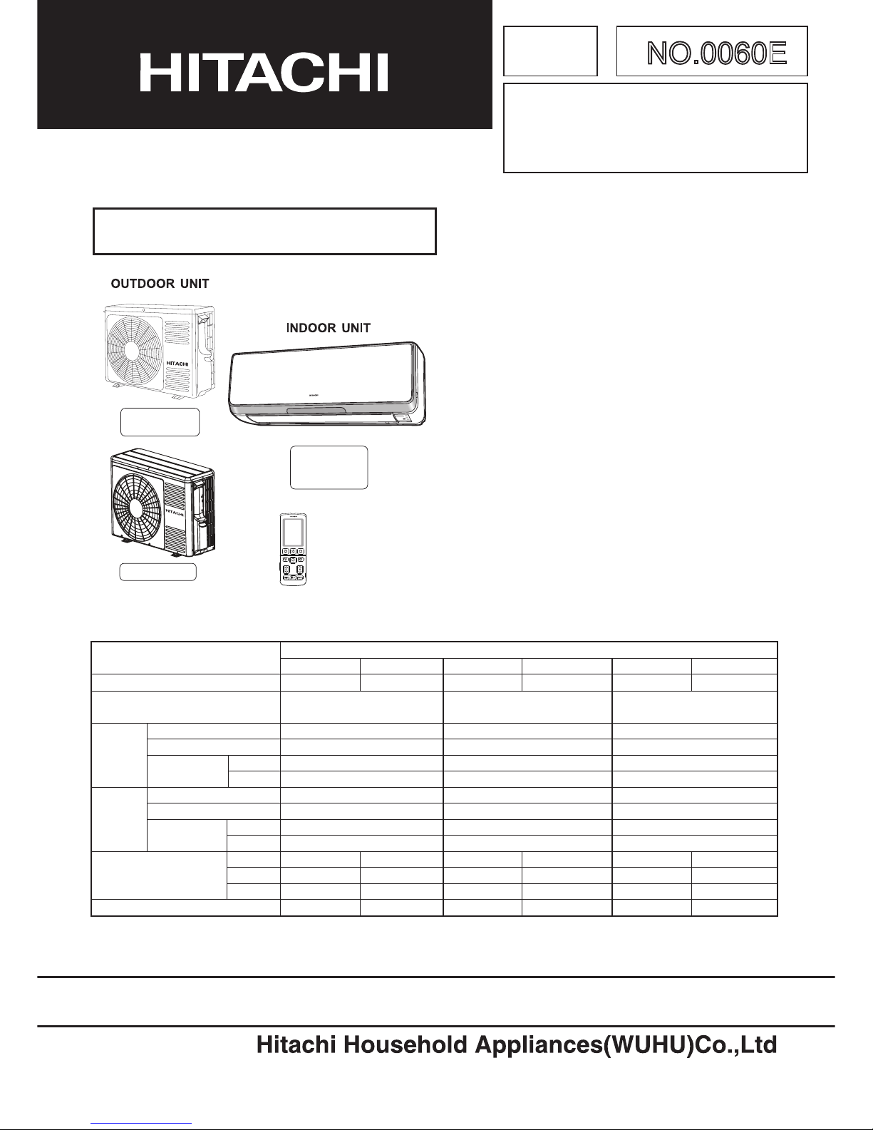
SERVICE MANUAL
TECHNICAL INFORMATION
REFER TO THE FOUNDATION MANUAL
ROOM AIR CONDITIONER
SPECIFICATIONS AND PARTS ARE SUBJECT TO CHANGE FOR IMPROVEMENT.
FOR SERVICE PERSONNEL ONLY
3HS01-CAR / 3HS01-SAR
3HS41-CAR / 3HS41-SAR
3HS81-CAR / 3HS81-SAR
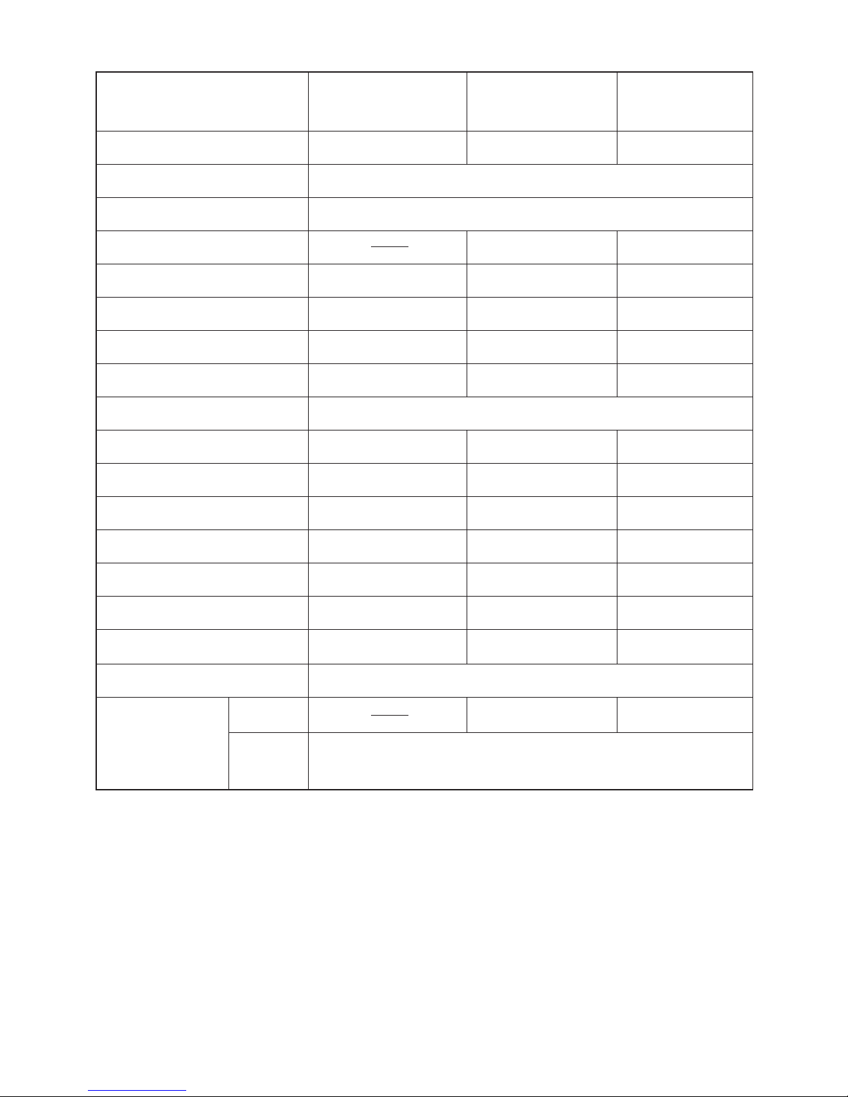
798
295
258
11
750 (+91)※
548
288 (+42)※
35
RAS-10SH3 RAC-10SH3
1ø, 220V, 50Hz
2.5 (1.6 - 3.1)
8,500 (5,400 - 10,540)
3.9
3.4 (1.7 - 4.2)
11,560 (5,780 - 14,280)
798
295
258
750 (+91)※
548
288 (+42)※
35
RAS-14SH3 RAC-14SH3
1ø, 220V, 50Hz
3.5 (1.6 - 3.8)
11,900 (5,440 - 12,920)
4.8
4.2 (1.7 - 5.2)
14,280 (5,780 - 17,680)
SPECIFICATIONS
SPECIFICATIONS‥‥‥‥‥‥‥‥‥‥‥‥‥‥‥‥‥‥‥
HOW TO USE ‥‥‥‥‥‥‥‥‥‥‥‥‥‥‥‥‥‥‥‥
CONSTRUCTION AND DIMENSIONAL DIAGRAM‥‥‥‥
MAIN PARTS COMPONENT‥‥‥‥‥‥‥‥‥‥‥‥‥‥
WIRING DIAGRAM ‥‥‥‥‥‥‥‥‥‥‥‥‥‥‥‥‥‥
WIRING DIAGRAM OF THE PRINTED WIRING BOARD
‥‥‥
BLOCK DIAGRAM ‥‥‥‥‥‥‥‥‥‥‥‥‥‥‥‥‥‥
BASIC MODE ‥‥‥‥‥‥‥‥‥‥‥‥‥‥‥‥‥‥‥‥
REFRIGERATING CYCLE DIAGRAM ‥‥‥‥‥‥‥‥‥
DISASSEMBLY & ASSEMBLY PROCEDURE ‥‥‥‥‥‥
DESCRIPTION OF MAIN CIRCUIT OPERATION ‥‥‥‥
SERVICE CALL Q&A ‥‥‥‥‥‥‥‥‥‥‥‥‥‥‥
TROUBLE SHOOTING ‥‥‥‥‥‥‥‥‥‥‥‥‥‥‥
PARTS LIST AND DIAGRAM ‥‥‥‥‥‥‥‥‥‥‥‥
CONTENTS
INDOOR UNIT + OUTDOOR UNIT
4
5
56
58
61
65
66
141
※After installation
DC INVERTER
COOLING
HEATING
TYPE
MODEL
POWER SOURCE
TOTAL INPUT
TOTAL AMPERES
CAPACITY
TOTAL INPUT
TOTAL AMPERES
CAPACITY
DIMENSIONS
NET WEIGHT
(mm)
(A)
(B.T.U./h)
W
H
D
(kg)
(kW)
(A)
(B.T.U./h)
(kW)
(W)
(W)
INDOOR UNIT
OUTDOOR UNIT
INDOOR UNIT
OUTDOOR UNIT
NO.0060E
600 (400 - 1,100)
3.2
780 (400 -1,100)
1,070 (400 - 1,300)
5.1
1,020 (400 -1,400)
11
MARCH 2012
RAS-10SH3
RAS-14SH3
RAS-18SH3
RAC-18SH3
PAM
RAC-10SH3
RAC-14SH3
798
295
258
792 (+91)※
600
299 (+46)※
41
RAS-18SH3 RAC-18SH3
1ø, 220V, 50Hz
5.2 (1.1 - 5.5)
17,680 (3,740 - 18,700)
7.62
6.2 (1.1 - 8.3)
21 080 (3,740 - 28 220)
INDOOR UNIT
OUTDOOR UNIT
1,600 (500 - 2,300)
7.4
1,660 (500 -2,700)
12
, ,
53
84
86
90
101
108
Page 2
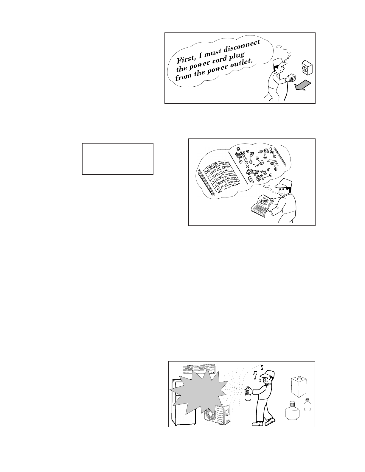
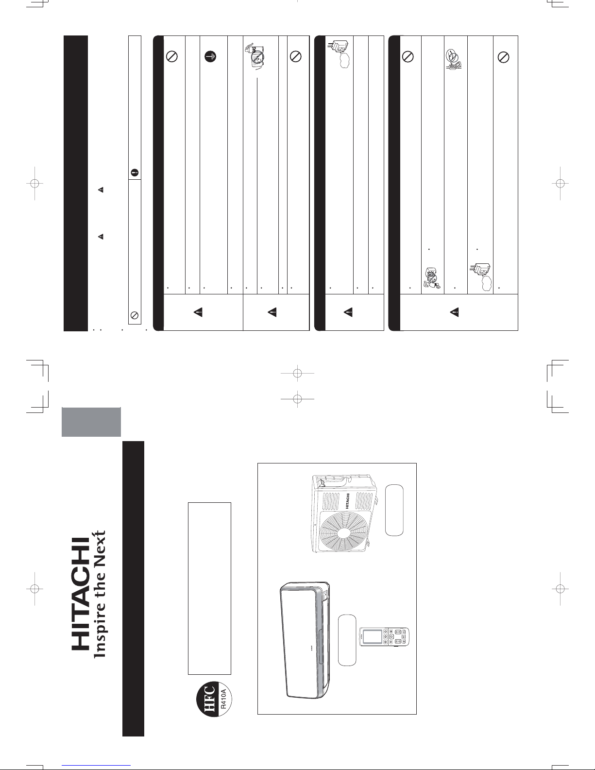
1. In order to disassemble and repair the
unit in question, be sure to disconnect the
power cord plug from the power outlet
before starting the work.
2. If it is necessary to replace any parts, they should be replaced with respective genuine parts for the unit,
and the replacement must be effected in correct manner according to the instructions in the Service
Manual of the unit.
3. After completion of repairs, the initial state should be
restored.
4. Lead wires should be connected and laid as in the
initial state.
5. Modification of the unit by the user himself should
absolutely be prohibited.
6. Tools and measuring instruments for use in repairs or inspection should be accurately calibrated in
advance.
7. In installing the unit having been repaired, be careful to prevent the occurrence of any accident such as
electrical shock, leak of current, or bodily injury due to the drop of any part.
8. To check the insulation of the unit, measure the insulation resistance between the power cord plug and
grounding terminal of the unit.
The insulation resistance should be 1MΩ or more as measured by a 500V DC megger.
9. The initial location of installation such as window, floor or the other should be checked for being safe
enough to support the repaired unit again.
If it is found not so strong and safe, the unit should be installed at the initial location after reinforced or
at a new location.
10. Any inflammable object must not be placed
about the location of installation.
11. Check the grounding to see whether it is
proper or not, and if it is found improper,
connect the grounding terminal to the earth.
Spray
gasoline
gasbombe
thinner
SAFETY DURING REPAIR WORK
If the contacts of electrical
parts are defective, replace
the electrical parts without
trying to repair them
1
2
3
4
5
DANGER
Page 3
– 1 –
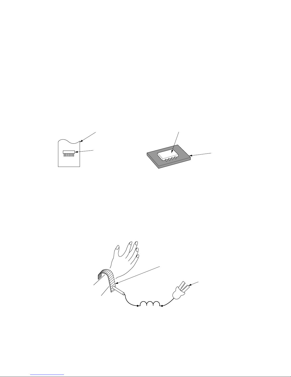
WORKING STANDARDS FOR PREVENTING BREAKAGE OF SEMICONDUCTORS
1. Scope
The standards provide for items to be generally observed in carrying and handling semiconductors in
relative manufactures during maintenance and handling thereof. (They apply the same to handling of
abnormal goods such as rejected goods being returned.)
2. Object parts
(1) Microcomputer
(2) Integrated circuits (I.C.)
(3) Field effective transistor (F.E.T.)
(4) P.C. boards or the like to which the parts mentioned in (1) and (2) of this paragraph are equipped.
3. Items to be observed in handling
(1) Use a conductive container for carrying and storing of parts. (Even rejected goods should be handled in
the same way.)
(2) When any part is handled uncovered (in counting, packing and the like), the handling person must
always use himself as a body earth. (Make yourself a body earth by passing one M ohm earth
resistance through a ring or bracelet.)
(3) Be careful not to touch the parts with your clothing when you hold a part even if a body earth is
being taken.
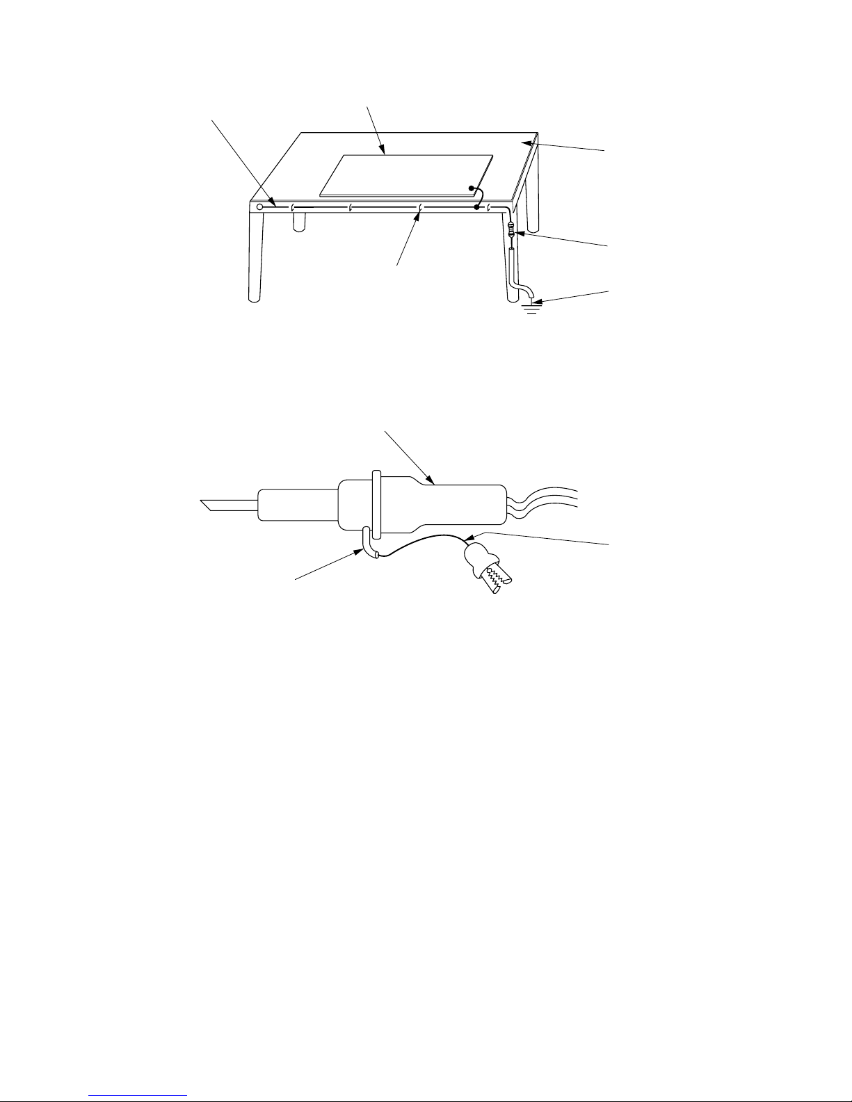
(4) Be sure to place a part on a metal plate with grounding.
(5) Be careful not to fail to turn off power when you repair the printed circuit board. At the same time,
try to repair the printed circuit board on a grounded metal plate.
H
I
T
A
C
H
I I
C
4
0
1
T
H
1
,
1
8
8
U
V
Fig. 1 Conductive container
A conductive polyvinyl bag
IC
IC
Conductive sponge
Fig. 2 Body earth
Body earth (Elimik conductive band)
Clip for connection with
a grounding wire
1MΩ
Page 4
– 2 –
(6) Use a three wire type soldering iron including a grounding wire.
Fig.4 Grounding a solder iron
Use a high insulation mode (100V, 10MΩ or higher) when ordinary iron is to be used.
(7) In checking circuits for maintenance, inspection, or some others, be careful not to have the test probes
of the measuring instrument short circuit a load circuit or the like.
Bare copper wire (for body earth)
Metal plate (of Al. stainless steel, etc.)
Working table
Resistor 1MΩ (1/2W)
Earth wire
Staple
Fig.3 Grounding of the working table
soldering iron
Grounding wire
Screw stop at the screwed
part using a rag plate
Page 5

– 3 –
1. In quiet operation or stopping the running, its heard slight flowing noise of
refrigerant in the refrigerating cycle occasionally, but this noise is not abnormal
for the operation.
2. When it thunders near by, it is recommend to stop the operation and to
disconnect the power cord plug from the power outlet for safety.
3. The room air conditioner dose not start automatically after recovery of the
electric power failure for preventing fuse blowing. Re-press START / STOP
button after 3 minutes from when unit stopped.
4. If the room air conditioner is stopped by adjusting thermostat, or miss
operation, and restart in a moment, there is occasion that the cooling and
heating operation does not start for 3 minutes, it is not abnormal and this is
the result of the operation of IC delay circuit. This IC delay circuit ensures
that there is no danger of blowing fuse or damaging parts even if operation is
restarted accidentally.
5. This room air conditioner should not be used at the cooling operation when the
outside temperature is below 22˚C (72˚F).
6. This room air conditioner (the reverse cycle) should not be used when the
outside temperature is below –20˚C (–4˚F).
If the reverse cycle is used under this condition, the outside heat exchanger is
frosted and efficiency falls.
7. When the outside heat exchanger is frosted, the front is melted by operating
the hot gas system, it is not trouble that at this time fan stops and the vapour
may rise from the outside heat exchanger.
CAUTION
Page 6
– 4 –
MODEL
FAN MOTOR
FAN MOTOR CAPACITOR
FAN MOTOR PROTECTOR
COMPRESSOR
OVER HEAT PROTECTOR
OVERLOAD RELAY
FUSE (for MICRO COMPUTER)
POWER RELAY, STICK RELAY
POWER SWITCH
TEMPORARY SWITCH
TEST SWITCH
TRANSFORMER
VARISTOR
NOISE SUPPRESSOR
THERMOSTAT
REFRIGERANT
CHARGING VOLUME
(R410A)
UNIT
PIPES
(MAX. 20m)
SPECIFICATIONS
REMOTE CONTROL SWITCH
(LIQUID CRYSTAL)
FUSE CAPACITY
30W (DC280V)
NO
NO
3A
G4AS
YES
NO
450NR
NO
YES (IC)
47W (DC380V)
YES
YES
25A, 2A, 3.15A
NO
NO
YES
450NR, TND05V
NO
NO
NO
WITHOUT REFRIGERANT BECAUSE COUPLING IS FLARE TYPE.
A INRUSH - WITH STAND TYPE
NO
NO
NO
1,150g 1,250g
RAS-10SH3
RAS-14SH3
RAS-18SH3
RAC-10SH3
RAC-14SH3
ASC092CD-A8JK
YES YES
47W (DC380V)
YES
YES
25A, 2A, 3A
NO
NO
YES
450NR, TND05V
NO
NO
NO
RAC-18SH
5RS132ZBA21
YES
YES (RZEA00794)
3
Page 7
OUTDOOR UNIT
INDOOR UNIT
– 1 –
Instruction manual
Page 1~48
To obtain the best performance and ensure years of trouble free use, please read this instruction manual completely.
RAS-10SH3 / RAC-10SH3
RAS-14SH3 / RAC-14SH3
SPLIT TYPE AIR CONDITIONER
INDOOR UNIT/OUTDOOR UNIT
MODEL
ENGLISH
DEUTSCHFRANÇAISITALIANOSPANISHPORTUGUÊS
∂ППЛУИО¿
«®¬¬¥£¤
RAS-10SH3
RAS-14SH3
RAC-10SH3
RAC-14SH3
Для достижения наивысшей производительности и обеспечения длительной безаварийной
внимательно изучите данную инструкцию .
Инструкция по эксплуатации
стр.
49 ~9 6
работы
10_14SH3_OM.indd 1
10_14SH3_OM.indd 1
2012-2-21 14:51:32
2012-2-21 14:51:32
• Please read the “Safety Precaution” carefully before operating the unit to ensure correct usage of the unit.
• Pay special attention to signs of “
Warning” and “ Caution”. The “Warning” section contains matters which, if
not observed strictly, may cause death or serious injury. The “Caution” section contains matters which may result
in serious consequences if not observed properly. Please observe all instructions strictly to ensure safety.
• The signs indicate the following meanings. (The following are examples of signs.)
• Please keep this manual after reading.
PRECAUTIONS DURING OPERATION
WARNING
WARNING
SAFETY PRECAUTION
• Do not reconstruct the unit.
Water leakage, fault, short circuit or fi re may occur if you reconstruct the unit by
yourself.
• Please ask your sales agent or qualified technician for the installation of your unit.
Water leakage, short circuit or fire may occur if you install the unit by yourself.
• Please use earth line.
Do not place the earth line near water or gas pipes, lightning-conductor, or the
earth line of telephone. Improper installation of earth line may cause electric
shock or fire.
• Be sure to use the specifi ed piping set for R410A. Otherwise, this may result in
broken copper pipes or faults.
• A circuit breaker should be installed depending on the mounting site of the unit.
Without a circuit breaker, the danger of electric shock exists.
• Do not install the unit near a location where there is fl ammable gas. The outdoor
unit may catch fi re if fl ammable gas leaks around it. Piping shall be suitable
supported with a maximum spacing of 1m between the supports.
• Please ensure smooth fl ow of water when installing the drain hose.
• Make sure that a single phase 220V power source is used.
The use of other power sources may cause electrical components to overheat
and lead to fi re.
PRECAUTIONS DURING INSTALLATION
PROHIBITION
CONNECT EARTH LINE
PROHIBITION
WARNING
CAUTION
•
• Should abnormal situation arise (like burning smell), please stop operating the
unit and remove plug from the socket. Contact your agent. Fault, short circuit or
fi re may occur if you continue to operate the unit under abnormal situation.
• Please contact your agent for maintenance. Improper self maintenance may cause electric
shock and fi re.
• Please contact your agent if you need to remove and reinstall the unit. Electric shock or fi re
may occur if you remove and reinstall the unit yourself improperly.
PRECAUTIONS DURING SHIFTING OR MAINTENANCE
• Do not use any conductor as fuse wire, this could cause fatal accident.
• During thunder storm, disconnect the plug top and turn off the circuit
breaker.
• Do not put objects like thin rods into the panel of blower and suction side
because the high-speed fan inside may cause danger.
• Spray cans and other combustibles should not be located within a meter of the
air outlets of both indoor and outdoor units.
As a spray can’s internal pressure can be increased by hot air, a rupture may result.
PROHIBITION
PROHIBITION
PROHIBITION
PROHIBITION
“OFF”
“OFF”
This sign in the fi gure indicates prohibition. Indicates the instructions that must be followed.
PROHIBITION
– 2 –
Avoid an extended period of direct airflow for your health.
10_14SH3_OM.indd 2
10_14SH3_OM.indd 2
2012-2-21 14:51:33
2012-2-21 14:51:33
Page 8

• Do not place plants directly under the airfl ow as it is bad for the plants.
• Do not direct the cool air coming out from the air-conditioner panel to face
household heating apparatus as this may affect the working of apparatus such
as the electric kettle, oven etc.
• The product shall be operated under the manufacturer specifi cation and not
for any other intended use.
PRECAUTIONS DURING OPERATION
CAUTION
• Do not attempt to operate the unit with wet hands, this could cause fatal
accident.
• When operating the unit with burning equipments, regularly ventilate
the room to avoid oxygen insuffi ciency.
• Please ensure that outdoor mounting frame is always stable, fi rm and without
defect. If not, the outdoor unit may collapse and cause danger.
• Do not wash the unit with water or place a water container such as a vase on
the indoor unit.
Electrical leakage could be present and cause electric shock.
• Be sure to stop the operation by using the remote controller and turn off the
circuit breaker during cleaning, the high-speed fan inside the unit may cause
danger.
• Turn off the circuit breaker if the unit is not be operated for a long period.
• Do not climb on the outdoor unit or put objects on it.
• When operating the unit with the door and windows opened, (the room
humidity is always above 80%) and with the air defl ector facing down or moving
automatically for a long period of time, water will condense on the air deflector
and drips down occasionally. This will wet your furniture. Therefore, do not
operate under such condition for a long time.
• If the amount of heat in the room is above the cooling or heating capability of
the unit (for example: more people entering the room, using heating equipments
and etc.), the preset room temperature cannot be achieved.
• Indoor unit cleaning must be performed by authorized personnel only. Consult
This appliance is not intended for use by young children or infirm persons unless they have been
Young children should be supervised to ensure that they do not play with the appliance.
your sales agent.
adequately supervised by a responsible person to ensure that they can use this appliance safely.
Using a commercially available detergent or similar can damage the plastic parts
or clog the drain pipe, causing water to drip with potential electric shock hazard.
• Do not touch the air outlet, bottom surface and aluminium fi n of the outdoor
unit.
You may get hurt.
Do not touch the refrigerant pipe and connecting valve.
Burns may result.
PROHIBITION
DON’T WET
PROHIBITION
PROHIBITION
PROHIBITION
DON’T TOUCH
“OFF”
PROHIBITION
PROHIBITION
PROHIBITION
PROHIBITION
PROHIBITION
DON’T TOUCH
STRICTLY OBSERVE
PRECAUTIONS
“OFF”
DEUTSCHFRANÇAISITALIANOSPANISHPORTUGUÊS
∂ППЛУИО¿
РУССКИЙ
– 3 –
ENGLISH
•
•
•
10_14SH3_OM.indd 3
10_14SH3_OM.indd 3
2012-2-21 14:51:33
2012-2-21 14:51:33
Drain Port (bottom)
Air Outlet
Discharges cool air when in heating
mode and warm air when in cooling
and dry cool modes, and warm or
cold air when in the dehumidifying
mode.
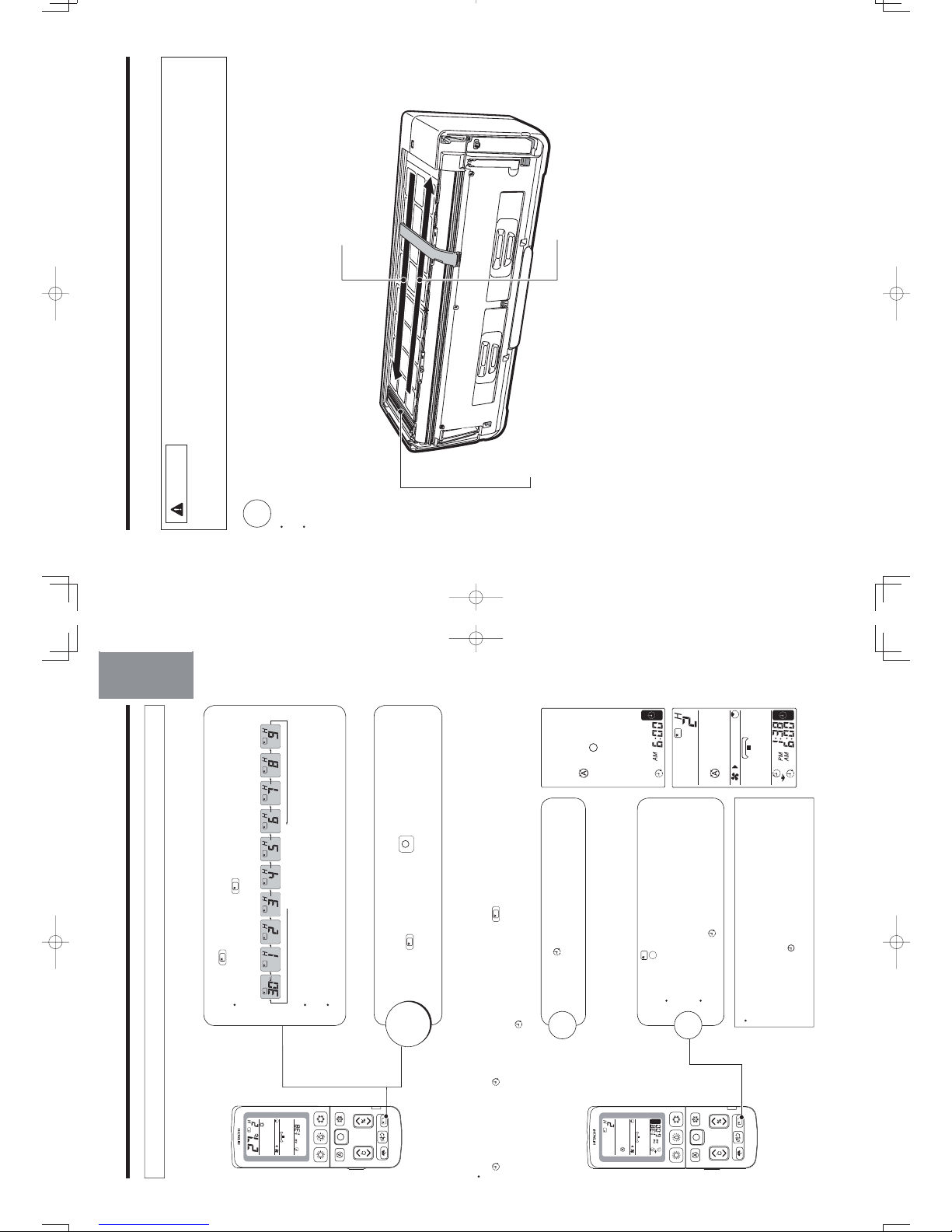
NAMES AND FUNCTIONS OF EACH PART
INDOOR UNIT
OUTDOOR UNIT
Signal Receiver
(internal)
Receive signal from the
remote control.
Indicator
Front Panel
(Page 8)
Horizontal/
Vertical Air Deflector
(internal)
Air Outlet
Remote Controller
Pipe/Wiring
Drain Hose
Drains dehumidified water generated from the indoor unit when in
the cooling, dehumidifying and dry cool modes.
Air Inlet (rear and left side)
噝 Even if the operation is stopped, the outdoor
unit fan continues to rotate for 10~60 seconds
to cool down the electrical parts.
噝 In heating operation, condensed water and
defrosted water is discharged from the outdoor
unit. Do not block the drain port as the water in
the drain may freeze in a cold area.
噝 Even during cooling operation, the water
condensed in the pipe, etc. may flow out from
the outdoor unit.
噝 When installing the outdoor unit under eaves,
etc. of the apartment, install a bush and drain
pipe on the drain port for drainage treatment.
ABOUT OUTDOOR UNIT
(Understanding The Operating Mechanism, page 39)
Earth Terminal
(side bottom)
噝 While the power is on, a very small amount of power is
consumed within the control circuit even when the unit
is not in operation.
Power can be saved if the circuit breaker is switched off.
CAUTION
Pull out the power plug if the unit is not in
use for a long period.
(Or turn off the circuit breaker.)
Infrared
Dynamic Air Deflection Sensor
Temporary Operation Switch
(Forced Cooling Switch)
When the remote
controller does not
work due to factors
like dead batteries,
you can press the
temporary operation
switch to start
temporary
operation. (Page 44)
– 4 –
Ion Mist Unit
10_14SH3_OM.indd 4
10_14SH3_OM.indd 4
2012-2-21 14:51:34
2012-2-21 14:51:34
Page 9
Air Cleaning Mesh Box
DEUTSCHFRANÇAISITALIANOSPANISHPORTUGUÊS
∂ППЛУИО¿
«®¬¬¥£¤
Replace the air cleaning mesh box.
Dž“Make sure that it clicks into place.”
Dž“If it dose not click into place, abnormal sounds
may be heard or the box may fall off.”
Close the front panel.
Ą
INDOOR UNIT CONTROL PANEL / CLEANING UNIT
Open the front panel to operate. (How to open the front panel, page 8)
Dust Catcher
Collects the dust swept by
the cleaning unit. (At front
and top.) (Page 37)
Cleaning Unit
Cleans the dust
caught by the
Dust Box
Collects and keeps the dust
that has been cleaned.
(Page 34)
Stainless Mesh Filter
(inside)
Collects particulates and dusts in the air. (Page 35)
Air Cleaning Mesh Box
Preparation
Stop the air conditioner, and disconnect
the power supply (or turn off the circuit breaker).
Open the front panel.
Pull out the air cleaning mesh box as illustrated to
remove it.
Insert the air cleaning mesh into the slot as illustrated.
Connect the power cord (or turn on the circuit breaker).
Jaw
Wasabi-Nano Titanium Air Cleaning Mesh
With the air cleaning mesh used, the air-conditioning capability will fall slightly.
Remove dust from the surface with a vacuum cleaner, and DO NOT clean it with water.
(We recommend you clean it once every 6 months and replace it once every 2 years.)
– 5 –
ENGLISH
stainless mesh
filter.
How to Attach the Wasabi-Nano Titanium Air Cleaning Mesh
10_14SH3_OM.indd 5
10_14SH3_OM.indd 5
2012-2-21 14:51:35
2012-2-21 14:51:35
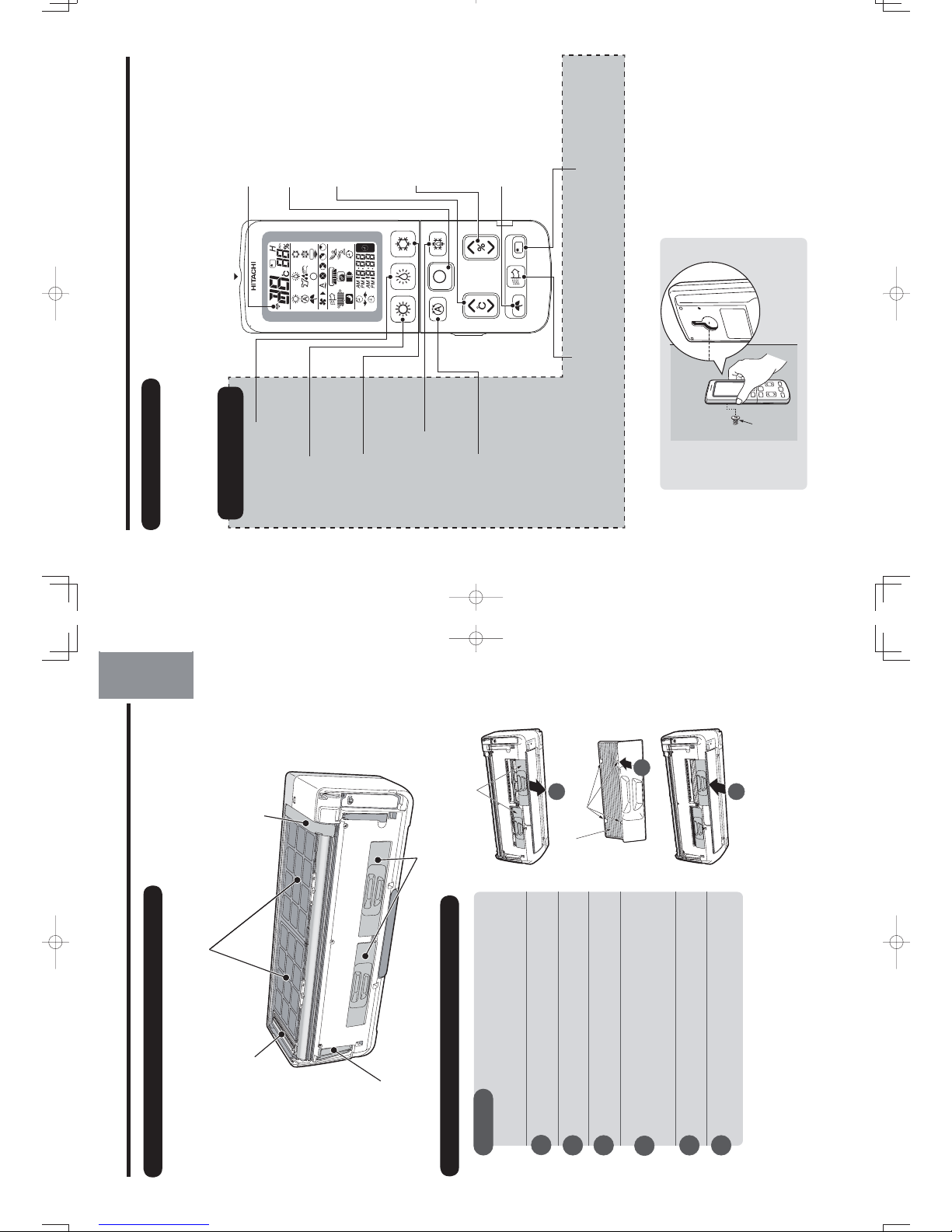
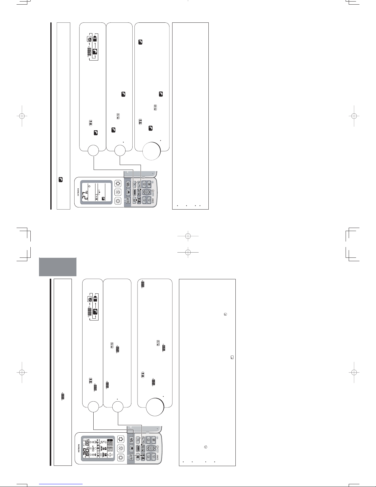
Transmission Indicator
The transmission indicator
ROOM TEMPERATURE
Button
Press this button to set the
room temperature. Keep
pressing and the value will
change more quickly.
STOP Button
HEAT Button
Press this button to start
heating operation.
(Page 14)
DEHUMIDIFY Button
Press this button to start
dehumidifying operation.
(Page 14)
COOL Button
Press this button to start
cooling operation.
(Page 15)
DRY COOL Button
Press this button to start dry
cool operation. (Page 16)
AUTO Button
Press this button to
start automatic operation.
(Page 13)
BUTTONS TO
START OPERATIONS
Remote controller can be used when it is fixed on a wall or pillar using the remote controller holder.
Before fixing it, make sure the indoor unit can be controlled from the remote controller fixing point.
SLEEP TIMER Operation Button
Press this button to start sleep timer
operation. (Page 29)
REMOTE CONTROLLER
Transmits the operation and timer settings to the indoor unit.
The LCD shown in the illustration below is the display immediately after the reset switch is pressed. Usually not
all the data are displayed. On the LCD shown below, the functions not available for this room air conditioner are
also displayed.
NAMES AND FUNCTIONS OF EACH PART (continued)
Transmission Part
HUMIDITY Button
Press this button to set the
humidity for dehumidify and
dry cool operations.
Screw
INFRARED HUMAN-PRESENCE
SENSING Button
Press this button to enter
the dynamic air deflection mode.
(Page 19, 20)
Press this button to start I on mist
operation.
– 6 –
Press this button to stop any
operation except the preset timer.
lit when a signal is sent.
ION MIST Button
(Page
18)
10_14SH3_OM.indd 6
10_14SH3_OM.indd 6
2012-2-21 14:51:35
2012-2-21 14:51:35
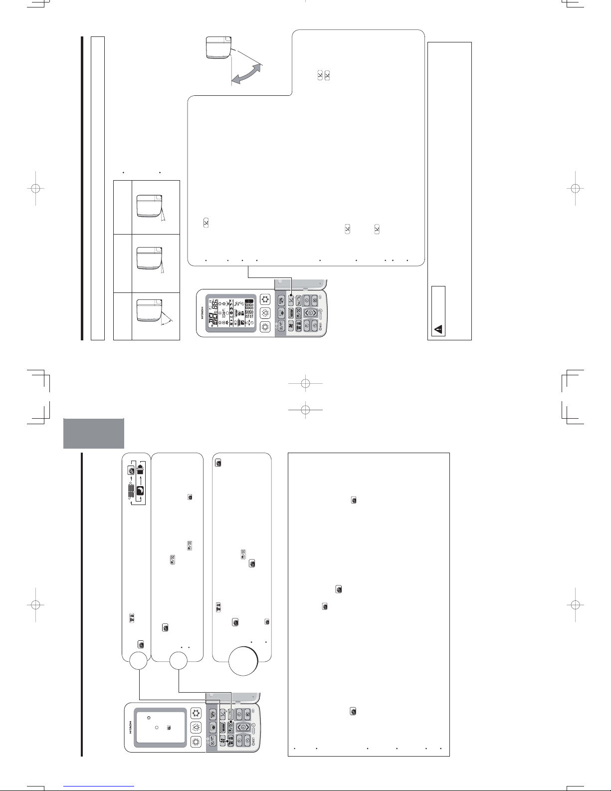
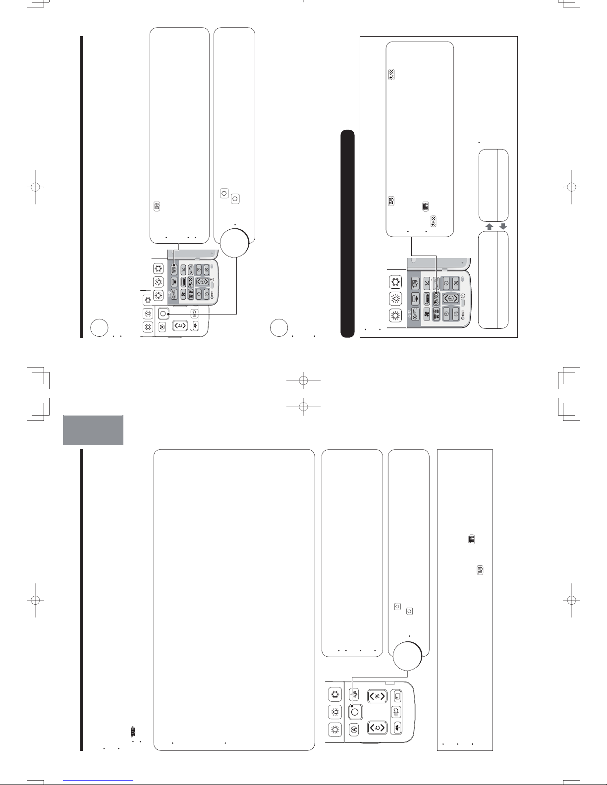
Page 10
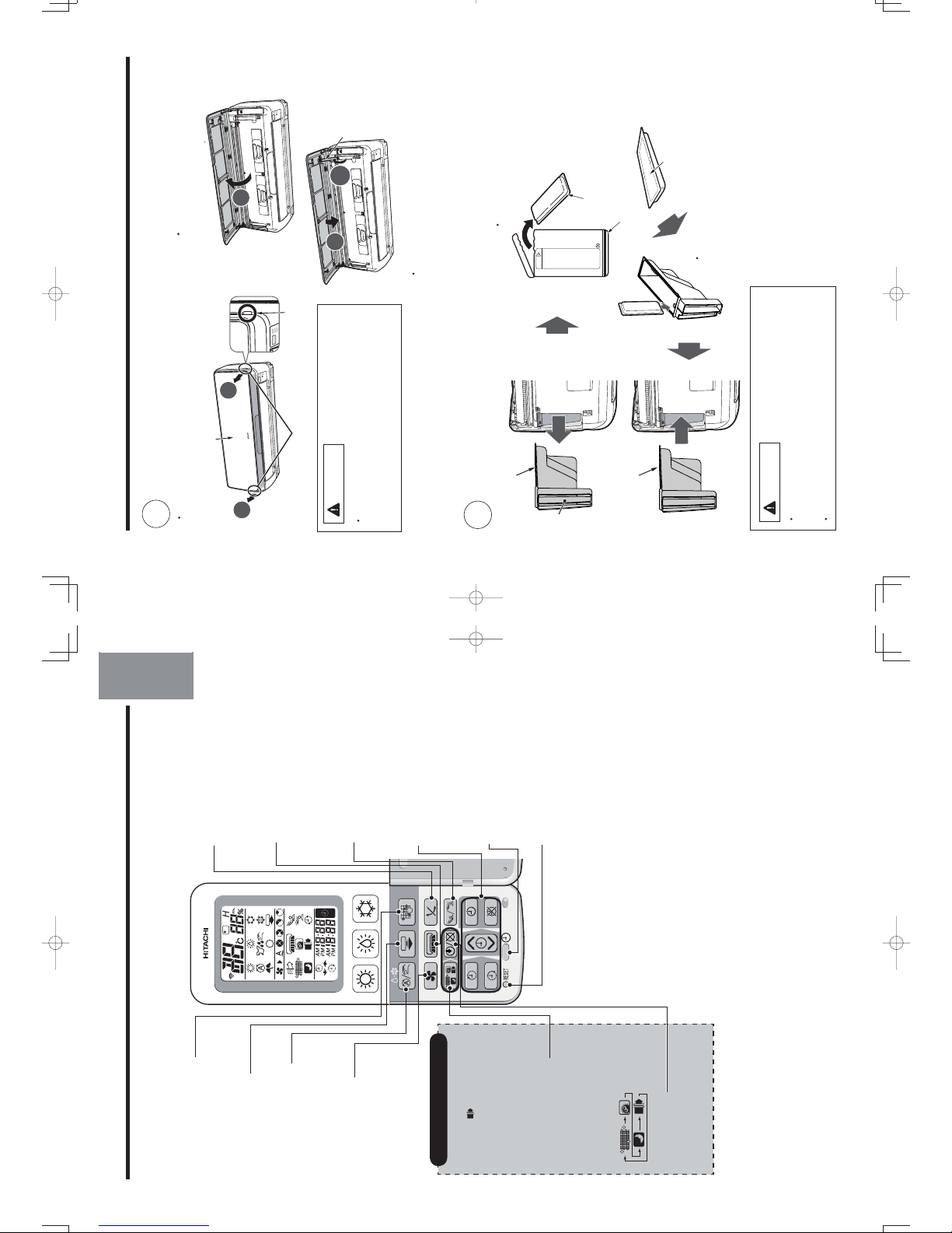
These are preset functions
except for
(SAVE).
Preset can be done if these
buttons are pressed while the
air conditioner is stopped,
however, the unit will not
function accordingly.
FUNCTION SELECTOR
Buttons
Each time when you press,
blinking changes in the
following sequence (page 12,
21, 22, 23):
ON/OFF Button
Use this button to set or cancel
the function selected by the
function selector.
FUNCTION SELECTOR
(When the door is open)
MANUAL CLEAN Button
Starts filter cleaning operation
while the air conditioner
operation is stopped. (Page 32)
FAN SPEED Button
Press this button to
select fan speed.
VERTICAL AIRFLOW Button
Use this button to swing the
vertical air deflector or to adjust
the angle to your preference.
(Page 24)
HORIZONTAL AIRFLOW
Button
Use this button to swing the
horizontal air deflector or
to adjust the angle to your
preference. (Page 25)
SET TIME Button
Use this button to set and
check the current time.
(Page 11)
TIMER Buttons
RESET Button
Press this button after the
batteries are replaced and
when the air conditioner does
not function properly. (Page 11)
DEUTSCHFRANÇAISITALIANOSPANISHPORTUGUÊS
∂ППЛУИО¿
РУССКИЙ
POWERFULL Button
Press this button to start
powerful operation. (Page 18)
MANUAL/AUTO Button
Press this button to switch
between auto/manual
dehumidifying and dry
cool operation. (Page 17)
Four options are available:
Auto, H i, M ed,L ow,and Silent.
DYNAMIC AIR DEFLECTION
Button
Press this button to start
dynamic air operation.
(Page 20)
– 7 –
ENGLISH
10_14SH3_OM.indd 7
10_14SH3_OM.indd 7
2012-2-21 14:51:36
2012-2-21 14:51:36
•
2
•
Take out the anti-mold wasabi
cassette from the aluminium bag.
Do not remove or tear
the aluminium sheet on
the surface nor make a
hole on it.
•
Remove the dust box housing
Dust Box Housing
Dust Box Housing
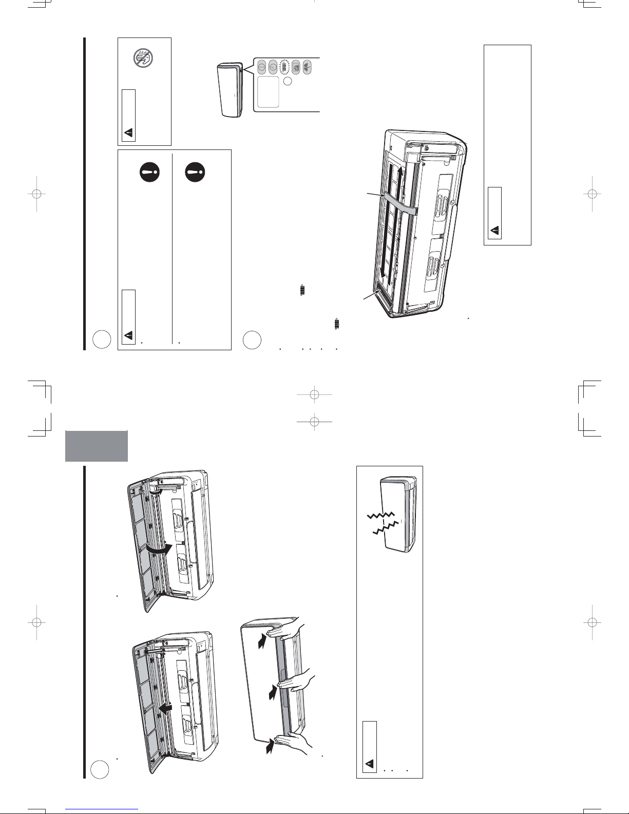
INSTALLING ANTI-MOLD WASABI CASSETTE
Open the front panel.
•
Do not hold the movable panel
when opening and closing the
front panel.
Front panel
Gripping part
Gripping part
Panel support
•
Hold and lift up the front panel.
•
Push up the panel support until it
clicks to lock it.
Lower the front panel and fix in
position with the panel support.
Install the anti-mold wasabi cassette.
Aluminium bag
Slide the anti-mold
wasabi cassette that
has been taken out of
the wrapper directly
into the Dust Box
Housing.
CAUTION
• Do not put your face close to the package when
you open it.
Your eyes or nose may be irritated by wasabi aroma.
• Do NOT eat.
1
No daily maintenance is required. However,
the effectiveness of anti-mold wasabi cassette
will be lost after approximately 10 years have
elapsed. Replace the anti-mold wasabi cassette
in such event.
この中に「防カビわさびカセット」が入っています
●製品の取扱説明書を確認して確実に取り付けてください。
●開封時は顔を近づけないでください。
わさびの香り成分で、目や鼻に刺激を感じることがあります。
●「防カビわさびカセット」の表面のアルミシートを
はがしたり、破ったり、穴をあけたりしないでください。
「防カビわさびカセット」の効果がなくなります。
●食べられません。
注
意
CAUTION
•
Do not open the front panel during operation
.
It may interrupt the movable panel to work properly.
Be sure to stop
the operation first before opening
the front panel.
Anti-mold wasabi
cassette
– 8 –
10_14SH3_OM.indd 8
10_14SH3_OM.indd 8
2012-2-21 14:51:36
2012-2-21 14:51:36
Handle
Page 11
DEUTSCH
DEUTSCHFRANÇAISITALIANOSPANISHPORTUGUÊS
∂ППЛУИО¿
РУССКИЙ
Close the front panel.
•
Hold and lift up the front panel.
CAUTION
• If the front panel is loose, it may come off and drop.
• When opening the front panel upwards, please do not use excessive force.
If the front panel comes off the device, this may cause it to malfunction.
• When the front panel remains open, be sure to push up the panel
support.
•
Push down the panel support until it clicks.
Push the both ends of the front panel first and
then its center until it clicks.
•
Pull it downward.
3
– 9 –
ENGLISH
10_14SH3_OM.indd 9
10_14SH3_OM.indd 9
2012-2-21 14:51:38
2012-2-21 14:51:38
FILTER CLEANING UNIT OPERATION CHECK
Make sure the power plug is firmly plugged into the power outlet.
WARNING
• Be sure to use the power outlet exclusively for
air conditioner
Use of other power outlet may cause heat, which
could result in fire.
• Make sure that dust is not deposited on the
power plug and be sure to plug in until the blades
of the plug are fully inserted to avoid unstable
plug-in and dust from being accumulated
Use of air conditioner with dusty power plug or
improper power connection could result in electrical
shock or fire.
CAUTION
Do not operate with
wet hands
It may cause electric
shock.
Compulsory
Wet Hand
Prohibited
Performing operation check after the power is turned on.
Perform the filter cleaning unit operation check
• After the power is turned on (after the power plug is inserted into the power
outlet or after the circuit breaker is switched on after power failure), the
cleaning unit makes one cycle of back and forth movement.
• At this time, the
(CLEAN) indicator is lit.
• One cycle of operation check will take approximately 5 minutes.
• During the operation check, the unit performs “Fan” operation while the movable
panel and horizontal air deflector remain closed.
• If the
(CLEAN) indicator blinks (lit for 4 seconds/off 1 second) after the
operation check, refer to “Troubleshooting” on page 44.
Cleaning Unit
There is a filter cleaning wiper inside.
Dust catcher
CAUTION
Do not put your fingers or a stick etc into the top surface during
the filter cleaning operation
It may result in injury or malfunction.
• The illustration shows the unit without front
panel for your reference only.
1
2
Compulsory
– 10 –
7(0325$5<
6:,7&+
10_14SH3_OM.indd 10
10_14SH3_OM.indd 10
2012-2-21 14:51:39
2012-2-21 14:51:39
Page 12

DEUTSCHFRANÇAISITALIANOSPANISHPORTUGUÊS
∂ППЛУИО¿
РУССКИЙ
DEUTSCH
Address
Address
PREPARE THE REMOTE CONTROLLER
Install the batteries.
• Use two AAA-size batteries.
Set the current time (Ex: set to 1:30 p.m.)
RESET
1
2
Press the (TIMER) button to adjust to the current time.
• You can fast forward the time by continuously pressing the
button.
Confirm the current time
• Press the
(SET TIME) button to check the current time
(The time display disappears 3 minutes later). If necessary,
readjust the time following the above procedure 1 and 2.
• Address selector switch is used to prevent
remote controller signal interference in such
circumstance where 2 indoor units are used in
the same room. This switch is not usually used.
(The factory setting is at “A” side.)
For this setting, please make an inquiry to your
sales agent.
Address selector
switch
Switch lever
Remote controller
backside
Do not operate by yourself.
Push mark
and pull.
ABOUT ADDRESS SELECTOR SWITCH
Time is incremented
Time is decremented
Press
(SET TIME) button to set the current time.
• “AM” or “PM” is lit instead of
blinking. It automatically goes
off in 10 seconds.
1
2
Open the cover and press the RESET
button with a sharp tip item.
3
• 18:88 lights up on the current
time display and “AM” and
“PM” start blinking.
CAUTION
1. Do not mix new and old batteries, or
different type of batteries together.
2. Remove the batteries when you do
not use the remote controller for 2 or 3
months.
DEUTSCH
– 11 –
ENGLISH
10_14SH3_OM.indd 11
10_14SH3_OM.indd 11
2012-2-21 14:51:39
2012-2-21 14:51:39
1
While (SAVE) is blinking, point the remote controller towards
the unit and press the (ON/OFF) button.
• A short beep sounds and
(SAVE) indicator turns on.
Press the (FUNCTION SELECTOR)
button until
(SAVE) blinks.
Press the (FUNCTION SELECTOR) button again until
(SAVE) blinks.
While
(SAVE) is blinking, point the remote controller towards
the unit and press the (ON/OFF) button.
• A short beep sounds and
(SAVE) indicator turns off, indicates
the setting is released.
Notes for “save” setting
• If ampere is set to “Save”, the maximum heating capacity slightly lowers
and starting up of heating operation will take a little longer. Besides,
the preset temperature may not be reached if outside temperature is
low.
• Point the remote controller to the signal receiver of the unit
Signal reception distance is approximately 7m in front of the unit.
However, this distance may be shorter or the signal may not be
receivable if there is an electronic lighting device in the same room.
• Handle the remote controller with care
Dropping it or getting it wet may compromise its signal transmission
capability. After new batteries are inserted into the remote controller,
the unit require approximately 10 seconds before it can respond to
commands and begin operation.
WHEN OPERATING THE REMOTE CONTROLLER
Approximately
7m from the front
PREPARE THE REMOTE CONTROLLER (continued)
Ampere setting (Standard/Save) can be selected.
If you experience frequent circuit breaker tripping, set ampere to “Save” to avoid this problem.
(Ampere is set to “Standard” at the time of purchase.)
4
2
RELEASE
– 12 –
10_14SH3_OM.indd 12
10_14SH3_OM.indd 12
2012-2-21 14:51:40
2012-2-21 14:51:40
Page 13
SPANISHPORTUGUÊS
∂ППЛУИО¿
РУССКИЙ
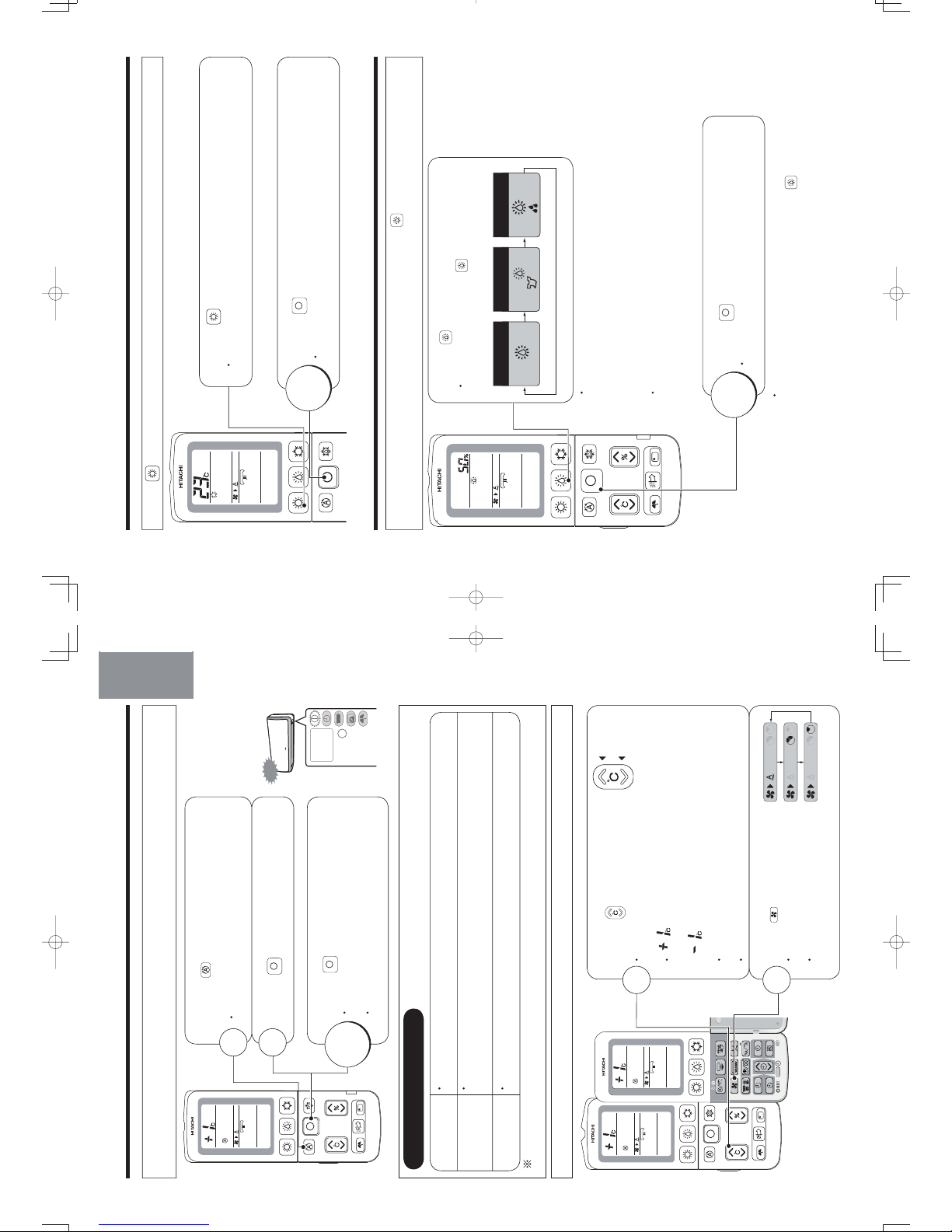
AUTOMATIC OPERATION
•
•
•
nj
1
2
2
1
7(0325$5<
6:,7&+
Based on the room temperature and outside temperature, the unit determines the most suitable operation
mode (heating, dehumidifying or cooling) and a comfortable temperature. (Set the current time on the remote
controller before starting operation.)
Press the (AUTOMATIC OPERATION) button
to set the operation mode to auto.
•
Every time you press it, the mode will change as
shown in the chart on the right.
Press the (STOP) button.
Press the (STOP) button again.
A short beep sounds and the automatic
operation stops.
Operation mode will be displayed on the
remote controller display.
Increase
Decrease
Adjust the room temperature
Press the (ROOM TEMPERATURE)
button.
• Every time you press it, a short beep sounds and the
temperature will change by 1°C.
•
is displayed if the temperature is set higher than
the automatically set room temperature by 1°C.
is displayed if the temperature is set lower than the
automatically set room temperature by 1°C.
• The adjustable temperature range is not higher or lower
than 3°C of the automatically set room temperature.
• Humidity setting cannot be adjusted.
Select the fan speed
Press the (FAN SPEED) button.
• “AUTO”, “LOW” and “SILENT”
can be selected.
• Every time you press it, the
mode will change as shown in
the chart on the right.
Beep
STOP
• Performs heating operation when the room temperature is below 23°C.
Set the temperature to be around 23°C.
• Performs dehumidifying operation when the room temperature is 23~26°C.
The preset temperature will be the room temperature at the time of start of air conditioner
operation.
• Performs cooling operation when the room temperature is above 27°C.
Set the temperature to be around 27°C.
Room temperature and fan speed can be adjusted to your preference.
AUTOMATIC OPERATION
Heating
Dehumidifying
Cooling
Even if dehumidifying operation is set, the air conditioner may not execute dehumidifying if the room humidity
is not very high. This is not a malfunction.
DEUTSCHFRANÇAISITALIANOSPANISHPORTUGUÊS
∂ППЛУИО¿
РУССКИЙ
– 13 –
ENGLISH
10_14SH3_OM.indd 13
10_14SH3_OM.indd 13
2012-2-21 14:51:41
2012-2-21 14:51:41
•
•
•
HEATING OPERATION
Press the (HEAT) button to start heating operation.
Press the (HEAT) button.
• Adjust the room temperature and fan speed to your preference.
Temperature range between 16°C~32°C can be set.
Press the (STOP) button.
A short beep sounds and heating operation stops.
STOP
DEHUMIDIFYING OPERATION
3 types of dehumidifying operations can be performed by pressing the (DEHUMIDIFY) button.
Performs powerful dry operation without lower down the room temperature.
Press the (DEHUMIDIFY) button.
• Every time you press the (DEHUMIDIFY) button,
the mode will change as shown in the chart below.
Condensation
Control
Auto
Dehumidifying
Quick
Laundry
(“AUTO” flashes for 5 seconds)
•
In auto dehumidifying mode, fine adjustment of room temperature, humidity
adjustment and fan speed selection can be made to your preference.
Every time you press the ROOM TEMPERATURE button, the temperature will change
by 1°C. (Temperature setting range is not higher or lower than 3°C.) Every time
you press the HUMIDITY button, the humidity will change by 5%. (Humidity setting
range is 40%~70%.)
• In quick laundry mode, fine adjustment of room temperature and fan speed
Press the (STOP) button.
• A short beep sounds and dehumidifying operation stops.
STOP
• After the dehumidifying operation is stopped, the remote controller will display the
operation mode that had been set before the (DEHUMIDIFY) button was
pressed.
ENGLISH
DEUTSCHFRANÇAISITALIANOSPANISHPORTUGUÊS
∂ППЛУИО¿
РУССКИЙ
– 14 –
selection can be made to your preference. (Fine adjustment of room
temperature and humidity adjustment cannot be made in condensation
control mode.)
10_14SH3_OM.indd 14
10_14SH3_OM.indd 14
2012-2-21 14:51:41
2012-2-21 14:51:41
Page 14
DEHUMIDIFYING OPERATION (continued)
Auto
Dehumidifying
Operation mode In this situation
Operating mechanism
• In damp
weather
• In most of the cases, the room temperature at the time the button is
pressed becomes the preset temperature.
(
When room temperature is below 12°C, set 13°C. When it is
13°C~22°C, set +2°C. When it is below 23°C~26°C, set room
temperature. When it is above 26°C, set 26°C)
• Target humidity is around 50~60%. If the humidity becomes lower than
the target value, operation stops. If it becomes higher than the target
value, operation resume.
• The operation mode may automatically be switched to cooling or
heating for temperature control. (Refer to table below)
• To dry the
laundry
quickly
• Detects outdoor temperature, room temperature and humidity to
automatically select the most suitable combination of heating and
powerful dehumidifying operations.
• This operation is performed together with stainless plasma air purifying
operation.
• Priority is given to laundry drying.
Be sure use this mode when no one is in the room as the room
temperature and humidity will be high temporarily.
• 3-hour timer function is used for this operation mode.
• When
controlling
condensation
formed on
windows in
winter time
• To control the condensation, priority is given to the operation for
lowering humidity. Therefore, the room temperature goes down in
this operation mode. The operation stops if the room temperature
becomes 1°C or below.
• 2-hour timer function is used for this operation mode.
Condensation
Control
Quick Laundry
• Be careful when condensation control operation is performed if the outside temperature is low as it will lower the
room temperature.
• (OFF TIMER) and (ON TIMER) (page 26), which are to be set using clock function, are not available during
dehumidifying (quick laundry and condensation control modes) operation. However, the timer (for 30 minutes
and 1-9 hours) can be set for quick laundry and condensation control modes with the (SLEEP) button.
• To set to your desired temperature and humidity while executing dehumidifying, it is recommended to use manual
dehumidifying function. (Page 17)
• If you do not wish room temperature to be too high when drying the laundry, use the preference (Powerful) mode
instead of quick laundry mode. (Page 18)
The operation mode may automatically be switched to cooling or heating for temperature control.
At this time, the room humidity may vary by approximately 10%.
Heating
operation
Dehumidifying operation
Operation
stop
Cooling
operation
About 3
°C
Approx. 3°C if outside temp. is
below approx. 32°C.
Approx. 1°C if outside temp. is
above approx. 32°C.
Room temperature set
Current room temperature
1ºC
COOLING OPERATION
Press the (COOL) button to start cooling operation.
Press the
(COOL) button.
• Adjust the room temperature and fan speed to your preference.
Temperature range between 16°C~32°C can be set.
Press the
(STOP) button.
• A short beep sounds and cooling operation stops.
STOP
– 15 –
ENGLISH
10_14SH3_OM.indd 15
10_14SH3_OM.indd 15
2012-2-21 14:51:42
2012-2-21 14:51:42
•
If you want to set the desired temperature and humidity during dry cool operation, we recommend
you use the manual cooling operation. (Page 17)
STOP
DRY COOL OPERATION
When you operates cooling operation with the dry function, press the (DRY COOL) button, the air conditioner
automatically sets temperature and humidity in dry cool mode.
Press the (DRY COOL) button.
•
Adjust the room temperature and fan speed to your preference.
• Every time you press the (ROOM TEMPERATURE) button, the
temperature will change by 1°C.
(Temperature setting range from the auto set temperature is not higher or
lower than 3°C.)
Press the (STOP) button.
• A short beep sounds and dry cool operation stops.
Humidity
to be set
Temperature
to be set
Based on the detected outside and room temperature,
the temperature is set on an hourly basis within the range
of 24~28°C.
• Even if the room temperature
reached the preset temperature,
the air conditioner may continue
to operate if the preset humidity
has not been reached.
50% when temperature above 27°C is set.
55% when temperature of 26°C is set.
60% when temperature below 25°C is set.
Dry
intermittent
operation
Dry cool operation
Operation
stops
Cooling
operation
About 3ºC
Approx. 3°C if outside temp. is
below approx. 32°C.
Approx. 1°C if outside temp. is
above approx. 32°C.
Room temperature set Current room temperature
About 1ºC
The operation mode may automatically be switched to cooling or heating for temperature control.
If the room temperature is lower than the preset temperature, intermittent operation (repeat of operation state
and stop state) is performed to avoid excessive lowering of temperature and to control the humidity.
DEUTSCHFRANÇAISITALIANOSPANISHPORTUGUÊS
∂ППЛУИО¿
РУССКИЙ
– 16 –
10_14SH3_OM.indd 16
10_14SH3_OM.indd 16
2012-2-21 14:51:42
2012-2-21 14:51:42
Page 15

ĄThe default setting is AUTO.
DžAdjustment Range of Dehumidifying Operation
Room Temperature
Room Temperature
Humidity
Humidity
Automatically adjusted in the
range of
50% to 60%
Auto-controlled
temperature
±3°C
Auto-controlled
temperature
±3°C
Auto dry cool
operation
Manual dry cool
operation
DžAdjustment Range of Dry Cool Operation
Setting Range of AUTO/MANUAL Operation
•
Switches to the manual mode if the machine is working in the auto
dehu
midifying/dry cool operation.
•
Switches to the auto mode if the machine is working in the manual
dehu
midifying/dry cool operation.
Press the AUTO/MANUAL button.
Example: Dehumidifying
Indicates
MANUAL
40%~70%
40%~70%
40%~70%
SWITCHING BETWEEN AUTO/MANUAL DEHUMIDIFYING/DRY COOL OPERATION
The AUTO/MANUAL button allows you to set the temperature and humidity manually during
dehumidifying/
dry cool operation.
Auto dehumidifying
operation
Manual dehumidifying
operation
10°C~32°C
16°C~32°C
– 17 –
ENGLISH
10_14SH3_OM.indd 17
10_14SH3_OM.indd 17
2012-2-21 14:51:43
2012-2-21 14:51:43
噝Ion mist operation is the combined operation mode of the fan operation
and moisturizing operation.
噝If the Ion mist mode is set while the air conditiconer is in basic operation mode, the air purifying function by
the electric dust collector will operate together.
Press the (ION MIST) button.
噝Adjust the fan speed to your preference. “HI”, “MED”, “LOW”, “SILENT”
can be selected.
噝When only Ion mist operation is set,
and (ON TIMER) preset cannot be done.
(OFF TIMER)
Press the (STOP) button.
噝A short beep sounds and Ion mist
operation
stops.
STOP
Press the (ION MIST) button.
CANCEL
during
operation
POWERFUL OPERATION
噝
噝The airflow will be extended so that the air can reach even further during powerful operation.
(Extended Airflow)
Press the (POWERFUL PERATION) button during operation.
噝A short beep sounds and the preference (Powerful) operation starts.
( POWERFUL) indicator lit on the remote controller.)
CANCEL
Press the (POWERFUL PERATION) button again.
噝 POWERFUL) indicator turns off on the remote controller.
Operation mode In this situation
Operating mechanism
Heating
噝 When you want the room to be
a little warmer
噝 Set approximately 2°C higher than the preset
temperature. Powerful heating operation is
performed.
Cooling
噝 When you want a little cooler
air
噝 When you want the room to be
a little cooler
Auto Dehumidifying
噝 When you want to remove
humidity a little faster
噝 Laundry drying efficiency is enhanced.
噝 Condensation-control efficiency is enhanced.
Dehumidifying
噝 Set approximately 3°C lower than the preset
temperature. Powerful cooling operation is
performed.
噝 High speed dehumidifying operation is performed
aiming to achieve humidity of approximately 40%.
Condensation
Control
Quick Laundry
By pressing the (POWERFUL PERATION) button during auto, heating, dehumidifying, cooling or stainless
plasma air purifying operation, the air conditioner performs the “Powerful” operation.
ION MIST OPERATION
– 18 –
, the electric dust collector operation
,,,
10_14SH3_OM.indd 18
10_14SH3_OM.indd 18
2012-2-21 14:51:43
2012-2-21 14:51:43
Page 16
Example: Cooling
With the infrared sensor, the air conditioner can detect the activity level in a room and adjust the temperature
and humidity automatically, thus achieving the purpose of energy saving.
Press the INFRARED SENSOR button.
The infrared sensor automatically adjusts the
indoor temperature and humidity according to
the activity level in the room. However, the
temperature
and humidity specified by the
remote controller remain unchanged.
1
•
The energy saving effect can be achieved only after the energy-saving temperature control function keeps
working
for more than 2 hours.
In the energy-saving temperature-control mode, the energy consumption saved by the air conditioner varies with
the activity level.
•
INFRARED HUMAN PRESENCE SENSING FUNCTION
•
Sensor in operation
Operation mode
Reduces the preset temperature
in one of the following cases:
Operation Description
Heating
Cooling
Auto
Dehumidifying/Dry Cool
Dehumidifying/Dry Cool
Operation mode Actions in case of no person
eDecreases the temperature by 2°C.
eIncreases the temperature by 2°C .
eIncreases the temperature by 5–10%.
eEnergy-saving operation in auto mode.
•
•
•
●
●
●
●
·
·
Auto
Cooling
Heating
·
·
•
•
Raises the preset temperature
in one of the following cases:
Low activity level
Low indoor temperature
•
•
Increases the preset temperature
in one of the following cases:
Energy-saving operation in auto
mode.
The infrared sensor detects changes to the infrared generated by human bodies. Therefore, the accuracy
of infrared
sensor may be affected negatively in the following cases:
e
e
The activity level is very low (reading, watching TV, etc.) or human bodies are blocked by a screen, cabinet, or glass board.
e
e
The indoor temperature is very high and exceeds or approaches the human body temperature (when the refrigeration
just begins).
e
e
The person wears thick clothes and turns his/her back to the air conditioner.
e
e
Curtains or plant leaves swing due to pet movement or airflow.
Low activity level
Low indoor temperature
•
•
The tracing function (Page 20) can further reduce the energy consumption.
After detecting that the person leaves the room for 30 minutes, the air conditioner turns to the energy-saving modes
according to the settings in the remote controller as shown in the right table, but the preset temperature and humidity
in the remote controller remain unchanged.
When the air conditioner works in powerful operation, setting the energy-saving mode will cancel the powerful operation.
High activity level
High indoor temperature
– 19 –
ENGLISH
10_14SH3_OM.indd 19
10_14SH3_OM.indd 19
2012-2-21 14:51:44
2012-2-21 14:51:44
DYNAMIC AIR DEFLECTION FUNCTION (TRACING/EVASION)
The infrared sensor can detect the position of people and automatically change the airflow direction.
Press the AUTO AIR DEFLECTION button to switch the air deflection
mode.
ƽHow to change the detection speed of the sensor of the dynamic air deflection (tracing/evasion) function:
e
There are 2 detection speeds: “Standard” (by intervals of 15"–3') and “Slow” (by intervals of 1'–10').
e
The remote controller is set to the standard speed by default.
e
When the detection speed of the sensor is too high, set the detection speed to “Slow”
(when people and pets in the room behave frequently, resulting in frequent changes to the airflow direction).
e
After the dynamic air deflection mode is set, the sensor usually works once every 15 seconds to 3 minutes to
detect the position of the person and adjusts the airflow direction accordingly.
(The airflow direction does not change with the movement of human body immediately.)
e
If the dynamic air deflection mode fails to achieve the desired effect, adjust the airflow direction manually.
e
When the machine works in cooling, dehumidifying, or dry cool operation after the dynamic air deflection is set,
if the indoor humidity/temperature is very high, the left/right/upper/lower air deflectors may change their angles
to prevent drop of condensed water. After the temperature falls, the air conditioner returns to the dynamic air
deflection status.
1
e(Tracing) Adjusts the airflow direction
automatically to send the air flow to
the location of the person.e(Tracing) Adjusts the airflow direction
automatically to keep the air flow away
from the location of the person.
e
Return to the setting prior to the dynamic
air deflection mode.
Pressing the
DYNAMIC
AIR DEFLECTION
button
Release the
Dynamic Air
Deflection button
Operation Description
Example: Heating
Hold down after the running stops
Select the desire setting.
(Finely tuned within +3 to -3. The indicator turns off 10 seconds later)
Press the (STOP) button eThe settings are saved.
Set the detection speed of the sensor to “Slow”.
After the running stops, hold down for more than 5 seconds while pressing and holding .
e
At this time, the air conditioner beeps for signal receiving.
e
Return to the “Standard” mode by repeating the above procedure (until the air conditioner beeps for
signal receiving).
In addition to “Standard” and “Slow” modes, you can also fine tune the detection speed of the sensor.
Fine tune the detection speed of the sensor
DEUTSCHFRANÇAISITALIANOSPANISHPORTUGUÊS
∂ППЛУИО¿
РУССКИЙ
– 20 –
10_14SH3_OM.indd 20
10_14SH3_OM.indd 20
2012-2-21 14:51:44
2012-2-21 14:51:44
Page 17
2
1
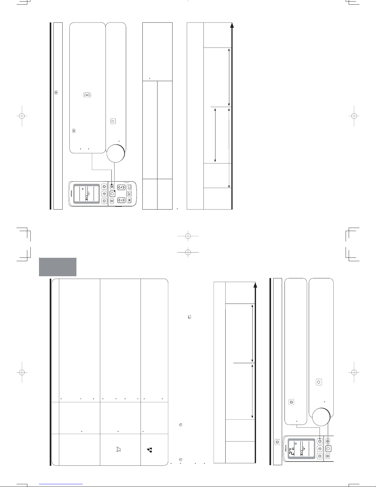
INTERNAL CLEANING OPERATION
The internal cleaning operation is automatically performed after cooling, dehumidifying or dry cool operation to
control mold growth by configuring the (INTERNAL CLEAN) operation. (There is no mold removing function
and disinfecting/sterilizing effect.)
Press the (FUNCTION SELECTOR) button
until (INTERNAL CLEAN) blinks.
While (INTERNAL CLEAN) is blinking, point the remote controller
towards the unit and press the (ON/OFF) button.
• A short beep sounds and (INTERNAL CLEAN) indicator turns on
at the remote controller.
Press the (FUNCTION SELECTOR) button again until
(INTERNAL CLEAN) blinks.
While (INTERNAL CLEAN) is blinking, point the remote controller
towards the unit and press the (ON/OFF) button.
• A short beep sounds and (INTERNAL CLEAN) indicator turns off
on the remote controller.
• Internal cleaning operation is not performed if the duration of cooling, dehumidifying or dry cool operation is
too short (below approximately 10 minutes).
• If the internal cleaning mode is set, the internal cleaning operation will automatically start when cooling,
dehumidifying or dry cool operation is stopped. During internal cleaning, the heating operation and fan operation
(with stainless plasma air purifying) are performed to control the mold growth inside the indoor unit.
• While (ON TIMER) is set, internal cleaning operation is not performed from 2 hours before the preset
time.
• Internal cleaning operation is not performed if the air conditioner operation is stopped in any of the following
conditions below.
(heating operation, stainless plasma air purifying operation, quick laundry operation and (OFF TIMER) stop
under condensation control operation, operation stopped by
(SLEEP) button.)
ENGLISH
DEUTSCHFRANÇAISITALIANOSPANISHPORTUGUÊS
∂ППЛУИО¿
РУССКИЙ
– 21 –
ENGLISH
STOP
10_14SH3_OM.indd 21
10_14SH3_OM.indd 21
2012-2-21 14:51:45
2012-2-21 14:51:45
1
2
By configuring (SLEEP) operation while the sleep timer is set for auto, heating, dehumidifying, cooling and
dry cool modes, the air conditioner supports your comfortable sleeping environment.
Press the (FUNCTION SELECTOR) button
until (SLEEP) blinks.
While (SLEEP) is blinking, point the remote controller towards the unit
and press the (ON/OFF) button.
• A short beep sounds and (SLEEP) indicator turns on on the remote
controller.
Press the (FUNCTION SELECTOR) button again until (SLEEP)
blinks.
While (SLEEP) is blinking, point the remote controller towards the
unit and press the (ON/OFF) button.
• A short beep sounds and (SLEEP) indicator turns off on the remote
controller.
STOP
• When in cooling operation, the temperature and humidity will be controlled in combination with dehumidifying
operation.
• When in dehumidifying or dry cool mode, temperature is controlled to a comfortable level with the preset
humidity target level of 60%.
• When in heating operation, temperature is controlled in the same manner as ordinary sleep mode.
• When in automatic operation, a control is executed according to the operation mode set by the auto
function.
– 22 –
SLEEP OPERATION
10_14SH3_OM.indd 22
10_14SH3_OM.indd 22
2012-2-21 14:51:45
2012-2-21 14:51:45
Page 18
1
2
The air conditioner detects indoor temperature and humidity. Once the temperature and humidity reaches to a
level conductive to mold growth, the dehumidifying and stainless plasma air purifying operations automatically
start.
Press the (FUNCTION SELECTOR) button until
(MOLD MONITOR) blinks.
While (MOLD MONITOR) is blinking, point the remote controller
towards the unit and press the (ON/OFF) button.
• Preset the mold monitor operation.
• During the mold monitor operation, (ON/OFF) and (MONITOR)
indicators on the indoor unit turns on.
Press the (FUNCTION SELECTOR) button again until
(MOLD MONITOR) blinks.
While (MOLD MONITOR) is blinking, point the remote controller
towards the unit and press the (ON/OFF) button.
• A short beep sounds and (MOLD MONITOR) indicator
turns
off
on the remote controller.
• The (MONITOR) indicator on the indoor unit turns off.
CANCEL
• Mold monitoring operation is a preset function. Even if mold monitoring mode is preset, the actual operation
will be performed only when the detected temperature and humidity has reached the level conducive to mold
growth.
• The setting of mold monitoring mode is valid for 2 weeks from the last remote control operation.
(If any remote control operation is performed while (MOLD MONITOR) is set, the preset mold monitoring
mode is valid for 2 weeks from such remote control operation.)
Once the above mentioned 2 weeks have elapsed, the (MONITOR) indicator on the indoor unit turns
off.
(However,
(MOLD MONITOR) indication on the remote controller remains on. If the (MONITOR)
indicator on the indoor unit is off, please reset or cancel the mold monitoring mode.)
• When mold monitoring mode is set, the fan operation is performed for approximately 3 minutes once every
approximately 20 minutes and the room temperature and humidity are detected.
(The movable panel and horizontal air deflector remain closed when temperature and humidity are
detected.)
• In the first cycle of mold monitoring operation, dehumidifying operation is performed for 4 hours consecutively
if the detected temperature and humidity are 10°C and more and 70% and more, respectively. From the
second cycle onwards, dehumidifying operation is performed if the detected temperature and humidity reach
the above mentioned level and will stop once the humidity has gone down.
• For the duration of 20 minutes after mold monitoring operation temporarily stops, the mold monitoring operation
is not performed immediately even if mold monitoring mode remains set and the humidity exceeds 70%.
• There is no function to remove mold that has grown.
– 23 –
ENGLISH
MOLD MONITOR OPERATION
10_14SH3_OM.indd 23
10_14SH3_OM.indd 23
2012-2-21 14:51:46
2012-2-21 14:51:46
60°
15°
10°
50°
ADJUSTING THE VERTICAL AIRFLOW DIRECTION
Please operate with the remote controller. (Moving by hands may cause malfunction.)
Cooling
operation
Heating
operation
Dehumidifying/
Dry Cool operation
About
About
About
Set automatically
• Air conditioner automatically set to the suitable
angle for each operation (Horizontal air deflector
only. The angle of the vertical air deflector is set to
the front). Usually vertical airflow direction control
is not required.
• If room temperature and humidity continue to be
high during cooling, dehumidifying or dry cool
operation, the angle of horizontal air deflector may
change to prevent dripping of condensed water.
Swing
angle
About
Horizontal
Vertical airflow swing
• When the (VERTICAL AIRFLOW) button is pressed,
a short beep sounds and the vertical air deflector repeats
swinging.
• When the air conditioner stops operation, the swing of the
vertical air deflector also stops and the air outlet closes.
• If the operation resumes, the vertical air deflector is
automatically set to the suitable angle for each operation.
• Even if the swing mode is set, the vertical air deflector may
stop swinging depending on the room temperature and
humidity. (Page 25)
(It may take approximately 10 seconds for the air deflector
to start moving. This is due to the checking operation to set
the air deflector to the correct angle.)
Vertical air flow of your preference
• To set the vertical airflow direction to your desired angle, press the (VERTICAL
AIRFLOW) button to move the vertical air deflector, and press the (VERTICAL
AIRFLOW) button again to stop air deflector at your desired angle.
Press the (VERTICAL AIRFLOW) button.
• A short beep sounds and the vertical air deflector repeats swinging.
(Vertical airflow swing)
Press the (VERTICAL AIRFLOW) button again at your preferred angle.
• The swing stops at the position where the button is pressed.
• The air outlet closes if the operation stops. The horizontal air deflector will return to
the preset position when the operation resumes.
• If the operation mode is changed, the horizontal air deflector will automatically be
set to the proper angle suitable for the newly set mode.
CAUTION
DO not operate long hours with cooling, dehumidifying, dry operation, airflow swing operation nor
the vertical air deflector in downward state.
Some dew may form on the vertical air deflector and drop which may wet your furniture.
ENGLISH
DEUTSCHFRANÇAISITALIANOSPANISHPORTUGUÊS
∂ППЛУИО¿
РУССКИЙ
– 24 –
10_14SH3_OM.indd 24
10_14SH3_OM.indd 24
2012-2-21 14:51:46
2012-2-21 14:51:46
Page 19
•
The movements of the left and right air deflectors displayed in the remote controllers
are not synchronous with movements of the actual air deflectors.
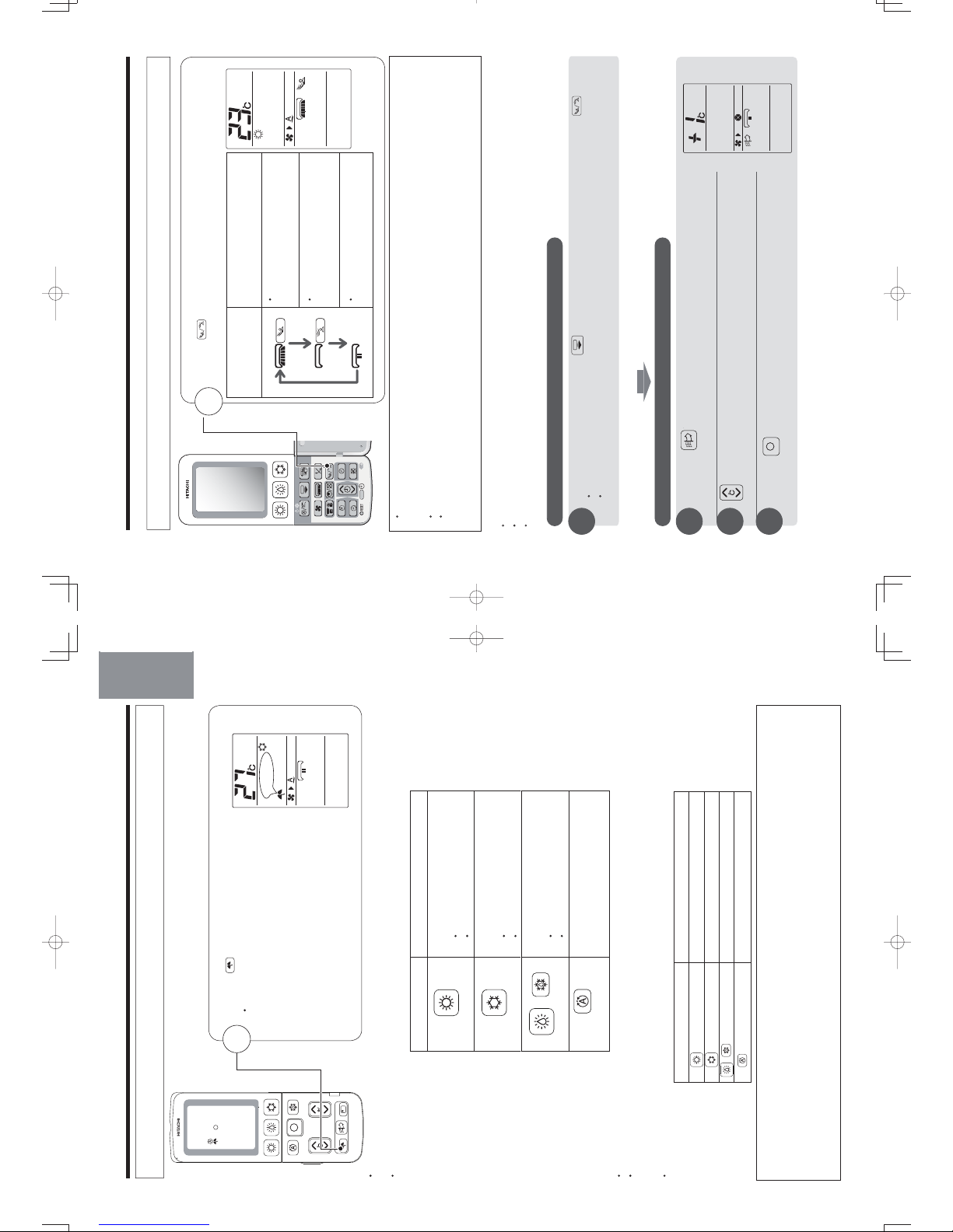
ADJUSTING THE HORIZONTAL AIRFLOW DIRECTION
Adjust the horizontal airflow direction
• The angle of horizontal airflow direction is set to the front at the
time of purchase.
• Every time the button is pressed, the mode of the horizontal air deflector
changes as below.
• A short beep sounds and the angle of the horizontal air deflector changes.
Front
Horizontal
swing
preferred angle
Horizontal angle of your preference
•
•
To set the horizontal airflow direction to your desired angle, move the
horizontal air deflector and press the (HORIZONTAL AIRFLOW) button
again to stop air deflector’s movement once it has reached your desired
angle.
Press the (HORIZONTAL AIRFLOW) button again to fix your preferred
angle during horizontal airflow swing.
• Fan speed may be increased depending on the angle of the horizontal air
deflector.
• Even if the horizontal airflow direction has been adjusted to your desired
angle, the angle of horizontal air deflector may change in the event the room
temperature and humidity continue to be high during cooling, dehumidifying
or dry cool operation. The angle will change back to your desired angle once
the temperature and humidity have been lowered by the air conditioning
operation.
CAUTION
Do not operate long hours with cooling, dehumidifying, dry cool operation and horizontal airflow swing
operation.
Some dew may form on the horizontal air deflector and drop which may wet your furniture.
In the following cases, the swing stops even when vertical swing and horizontal swing are set.
In Heating operation In Dehumidifying operation In Dry Cool operation
• During preheat operation.
• During defrost operation.
• When the room temperature
reaches the temperature which
had been set.
• When the humidity is reached
to the humidity which has been
set.
• When the room temperature is
below 1°C.
• When the temperature is below
the temperature which has been
set and the operation is stop.
The movement scope of the left/right air deflectors are set to the following
5 positions:
– 25 –
ENGLISH
10_14SH3_OM.indd 25
10_14SH3_OM.indd 25
2012-2-21 14:51:47
2012-2-21 14:51:47
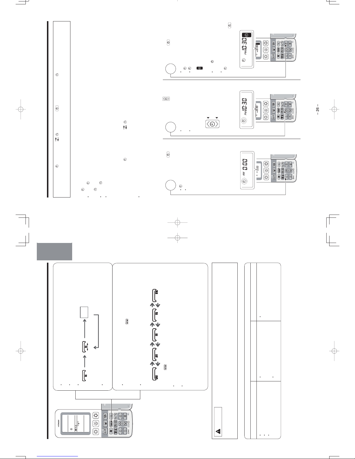
TIMER PRESET OPERATION
How to preset the timer
1
3
2
3 types of timers, (OFF TIMER) (ON TIMER), (OFF TIMER) and (ON TIMER) are available. Only
one of these timers can be preset at a time.
Operation mode, temperature, humidity and fan speed, etc. must be set before setting the timer.
For
(OFF TIMER) preset
• When
(OFF TIMER) is set, the operation stops at the preset time.
For
(ON TIMER) preset
• When
(ON TIMER) is set, the operation starts so that the preset temperature is reached at the preset time.
• The air conditioner starts operation a maximum of 60 minutes before the preset time, depending on conditions
including room temperature and preset temperature.
How to preset the (OFF TIMER) (ON TIMER)
(For example: When setting the timer to stop operation at 10:30 p.m. and your desired temperature is reached at
7:00 a.m.)
• The timer with earlier preset time will function first, based on the time at which the timer is set.
Press the
(OFF
TIMER) button.
•
(OFF TIMER) blinks.
• 0:00 a.m. or the previous preset
time is displayed.
Press the
(TIMER)
button to set the time.
• Time can be set in increments
of 10 minutes.
• The time can be fast-forwarded
by continuously pressing the
button.
Time is incremented
Time is decremented
Press the
(PRESET)
button.
• A short beep sounds and the
(OFF TIMER) is set.
•
(OFF TIMER) indication
stops blinking and lights up.
(TIMER SET) will be
displayed.
• The
(TIMER) indicator on the
indoor unit lights up.
• To change the preset time for
(OFF TIMER), return to
procedure and press the
(OFF TIMER) button.
10_14SH3_OM.indd 26
10_14SH3_OM.indd 26
2012-2-21 14:51:47
2012-2-21 14:51:47
Page 20
4
5
6
How to cancel the preset timer
Press the (CANCEL) button.
(All the preset timer will erase)
•
(OFF TIMER) / (ON TIMER), which are to be set using the clock function,
cannot be set during the operation set by the
(AIR
during the quick laundry or condensation control mode
PURIFYING) buttons or
operation.
under (DEHUMIDIFY)
• As the time settings are stored in memory in the remote controller, just press
the
(PRESET) button in order to use the same settings next time.
Press the
(ON
TIMER) button.
•
(ON TIMER) blinks.
• 6:00 a.m. or the previous preset
time is displayed.
•
display indicates the
sequence of
(OFF TIMER)
and
(ON TIMER) function.
Press the
(TIMER)
button to set the time.
• Time can be set in increments
of 10 minutes.
• The time can be fast-forwarded
by continuously pressing the
button.
Time is incremented
Time is decremented
Press the (PRESET)
button.
• A short beep sounds and the
(ON TIMER) is set.
•
(ON TIMER) indication stops
blinking and lights up.
(TIMER SET) will be
displayed.
• The
(TIMER) indicator on the
indoor unit lights up.
• To change the preset time
for
(ON TIMER), return to
procedure and press the
(ON TIMER) button.
ENGLISH
DEUTSCHFRANÇAISITALIANOSPANISHPORTUGUÊS
∂ППЛУИО¿
РУССКИЙ
DEUTSCHFRANÇAISITALIANOSPANISHPORTUGUÊS
∂ППЛУИО¿
РУССКИЙ
– 27 –
ENGLISH
10_14SH3_OM.indd 27
10_14SH3_OM.indd 27
2012-2-21 14:51:49
2012-2-21 14:51:49
1
2
FURTHER CONVENIENT TIMER FUNCTION
Dehumidifying (Condensation control) operation and
(ON TIMER) for heating operation can be set at the
same time.
Dehumidifying (Condensation control) operation controls the condensation which may occur in the morning
while
(ON TIMER) for heating operation warms up the room by the time you wake up.
Combination of (ON TIMER) and (DEHUMIDIFY) button
• Dehumidifying (Condensation control) operation and (ON TIMER) for heating operation for the next morning
can be set in combination before you go to sleep.
The display below is shown in the case where
(ON TIMER) is set for heating operation and then
dehumidifying operation (Condensation control) is executed at 11:38 p.m.
Preset the
(ON TIMER).
• When
(ON TIMER) is set, the air conditioner starts
operation so that the preset room temperature is
almost reached at the ON TIMER time. Check the
settings of the air conditioners when you set the timer.
(Page 26, 27)
Press the
(DEHUMIDIFY) button.
(
symbol is displayed)
• The dehumidifying (Condensation control) operation
stops at 1:38 a.m, two hours after the start of the
dehumidifying operation, and the heating operation
starts in order to reach the preset temperature by
6:00 a.m.
– 28 –
10_14SH3_OM.indd 28
10_14SH3_OM.indd 28
2012-2-21 14:51:49
2012-2-21 14:51:49
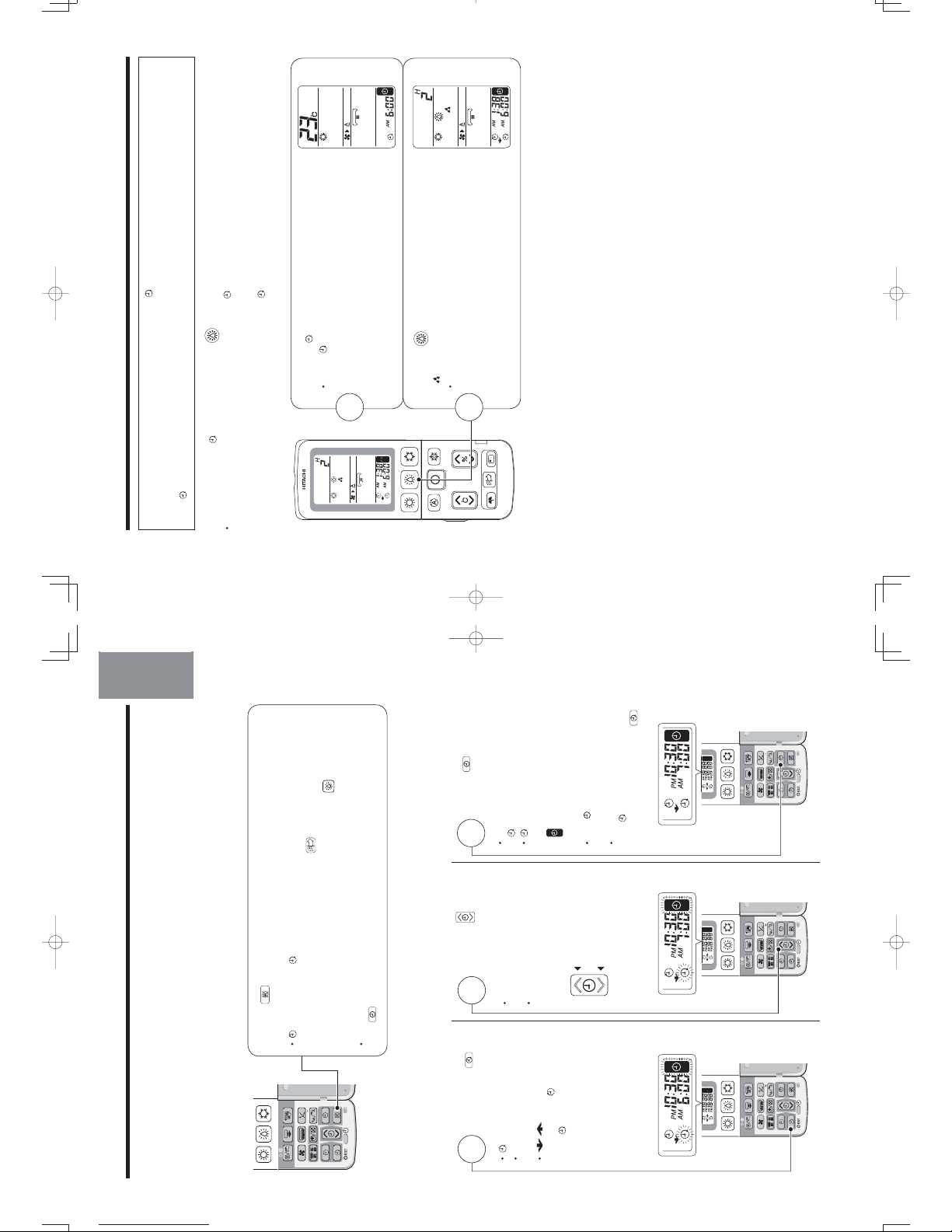
Page 21
1
2
SLEEP TIMER OPERATION
Configuring the fan speed appropriate for sleeping and stop the operation at specified time.
The display below indicates sleep timer which is set for 2 hours at 11:38 p.m. and the turn off time will be
1:38 p.m.
Press the (SLEEP) button.
• Every time you press the (SLEEP) button, the mode will change
as shown below.
Cancel the sleep timer
• Preset time of sleep timer and the time at which the operation stops
will be displayed on the remote controller.
• Fan speed remain “SILENT” during sleep timer operation.
CANCEL
Press the (SLEEP) button or (CANCEL) button.
Combination of Sleep Timer and On Timer operation
• Set the operation to auto stop by sleep timer operation, it can be set to start the operation next morning by
(ON TIMER). Set (ON TIMER) first and then press the (SLEEP) button.
The display below indicates
(ON TIMER) which is set at 6:00 a.m. and 2 hours sleep time at
11:38 p.m.
Preset the
(ON TIMER).
(Page 26, 27)
Press the
(SLEEP) button.
• The unit will turn off in 2 hours (at 1:38 a.m.)
and will turn on in order to reach the preset
temperature by 6:00 a.m.
•
The time range of sleep timer operation should
be set before (ON TIMER) time.
• When the sleep timer has been programmed, the unit
will not operate even if the set time is reached unless
the unit receives a signal from the remote controller.
Confirm that Sleep Timer programming is complete
(beep) and the
(TIMER) indicator of the indoor unit
turns on.
DEUTSCHFRANÇAISITALIANOSPANISHPORTUGUÊS
∂ППЛУИО¿
РУССКИЙ
– 29 –
ENGLISH
10_14SH3_OM.indd 29
10_14SH3_OM.indd 29
2012-2-21 14:51:50
2012-2-21 14:51:50
1
FILTER CLEANING OPERATION
(Filter Cleaning Unit Operation Check, page 10)
CAUTION
Do not put your fingers or a stick etc into the top part of the indoor unit during filter cleaning
operation.
It may result in injury or malfunction.
Automatic filter cleaning operation
• Automatically cleans the micro mesh stainless filter when the basic air-conditioning operation such as
cooling has ended. (Refer to page 31 for automatic filter cleaning operation)
• Automatic filter cleaning mode is set at the time of purchase.
Forward movement
Sweeps and collects the dust on the
micro mesh stainless filter.
Dust catcher
(1) Cleaning unit collects the dust
swept by the cleaning unit on
its forth movement.
(2) It turns over by the travelling
force of the cleaning unit which
is travelling back. At this time,
the dust collected by the dust
catcher is put into the dust
box.
Backward movement
Once the filter cleaning operation has been
completed, the cleaning unit returns to the
position at which air conditioning operation
is not obstructed.
– 30 –
10_14SH3_OM.indd 30
10_14SH3_OM.indd 30
2012-2-21 14:51:51
2012-2-21 14:51:51
Page 22
(Troubleshooting, page 41)
• The cleaning unit makes one cycle of back and forth movement to sweep the dust on the micro mesh
stainless filter and the dust catcher puts the collected dust into the dust box.
• One cycle of filter cleaning operation will take approximately 5 minutes.
•
(CLEAN) indicator lit during filter cleaning operation.
• Horizontal air deflectors remain closed when fan operation starts.
Conditions under which automatic filter cleaning is performed
• When the air conditioner operates for more than 15 minutes and stop, automatic filter cleaning is performed
in one of the following conditions.
(1) Accumulated operating hours of the air conditioner have exceeded 8 hours.
(2) Air conditioner is not operated for more than one week.
(To clean the dust which is naturally deposited on the top filter.)
CAUTION: The accumulated operating hours will not be reset if the automatic filter cleaning operation is
stopped before its completion.
• If the air conditioner is in operation continuously, the operation is stopped and automatic filter cleaning
operation is performed once 24 hours have elapsed.
After the completion of automatic filter cleaning, the operation will return to the operation mode which had
been set prior to the automatic filter cleaning.
Automatic filter cleaning is not performed if the air conditioner operation is stopped by sleep timer or off timer
function.
If you use sleep timer or off timer every time, manual filter cleaning should be executed approximately once
every 2~3 days. (Page 32)
However, if no manual filter cleaning is performed, automatic filter cleaning will be performed approximately
once a week after the air conditioner operation is stopped by sleep timer or off timer function to protect the
device.
About the noise during filter cleaning
• A whirring motor noise is generated due to driving of the cleaning unit.
• A clapping noise is generated when the dust catcher collects the dust
swept by the cleaning unit.
• A clapping noise is generated when the dust catcher is turned over by the
cleaning unit.
• A sweeping sound is generated when the cleaning unit sweeps the dust.
Press the (STOP) button twice.
• Press (STOP) button on the remote controller twice to
stop the process of filter cleaning operation.
STOP
• The air blown from the air conditioner will become softer when the air conditioner is operated immediately
after filter cleaning operation.
• Remove and clean the micro mesh stainless filter in the case where filter cleaning operation is prohibited.
(Page 35)
• Only during the filter cleaning operation that was started by pressing the
(MANUAL CLEAN) button on
the remote controller, the filter cleaning operation stops if the
(MANUAL CLEAN) button on the remote
controller is pressed one more time.
DEUTSCHFRANÇAISITALIANOSPANISHPORTUGUÊS
∂ППЛУИО¿
РУССКИЙ
– 31 –
ENGLISH
10_14SH3_OM.indd 31
10_14SH3_OM.indd 31
2012-2-21 14:51:51
2012-2-21 14:51:51
3
2
FILTER CLEANING OPERATION (continued)
Manual filter cleaning operation
Use the remote controller to run filter cleaning operation when the air conditioner operation is stop.
before it is initialized.
Press the
(MANUAL CLEAN) button when the air-conditioner stops.
•
•
•
•
•
The cleaning unit makes one cycle of back and forth movement to sweep
the dust on the micro mesh stainless filter and the dust catcher puts the
collected dust into the dust box.
• One cycle of filter cleaning operation will take approximately 5 minutes.
• During manual filter cleaning operation, movable panel and horizontal air
deflectors remain closed when fan operation starts.
STOP
Press the (STOP) button twice.
• Press
(STOP) button on the remote controller twice to stop the process
of filter cleaning operation.
Maintenance
(Maintenance, page 34)
HOW TO PROHIBIT THE FILTER CLEANING OPERATION
• With the remote controller, you can make a setting in which no filter cleaning operation is
performed.
• This setting should be made only when the air conditioner is stopped.
Press the (MANUAL CLEAN) button while pressing the (ON/OFF)
button (remain for 5 seconds).
• A double short beep sounds and the filter cleaning is not performed (filter
cleaning operation is prohibited) is set.
• If the
(MANUAL CLEAN) button is pressed while pressing down
the (ON/OFF) button again (hold the buttons for 5 seconds), a
single short beep sounds and the setting returns to the filter cleaning
operation.
Filter cleaning operation (Normal)
(at time of purchase)
“Beep” sound
Filter cleaning operation
is prohibited
“Beep Beep” sound
• If the filter cleaning operation is
prohibited, the operation check (page
10), automatic filter cleaning
operation and manual filter cleaning
operation are not performed.
– 32 –
If the air conditioner is not in use for a long period, it is recommended to manually run filter cleaning
No daily maintenance is required. However, dust amount varies depending on the environment in which
the air conditioner is used. Check the dust amount approximately once every two years and throw the
Greasy dirt can also be cleaned by the combined function of filter cleaning and micro mesh stainless filter. If the
dirt looks heavy, remove the micro mesh stainless filter, dust catcher and filter cleaning wiper to wash them with
water. (Maintenance, page 34~38)
dust, if any.
10_14SH3_OM.indd 32
10_14SH3_OM.indd 32
2012-2-21 14:51:52
2012-2-21 14:51:52
Page 23
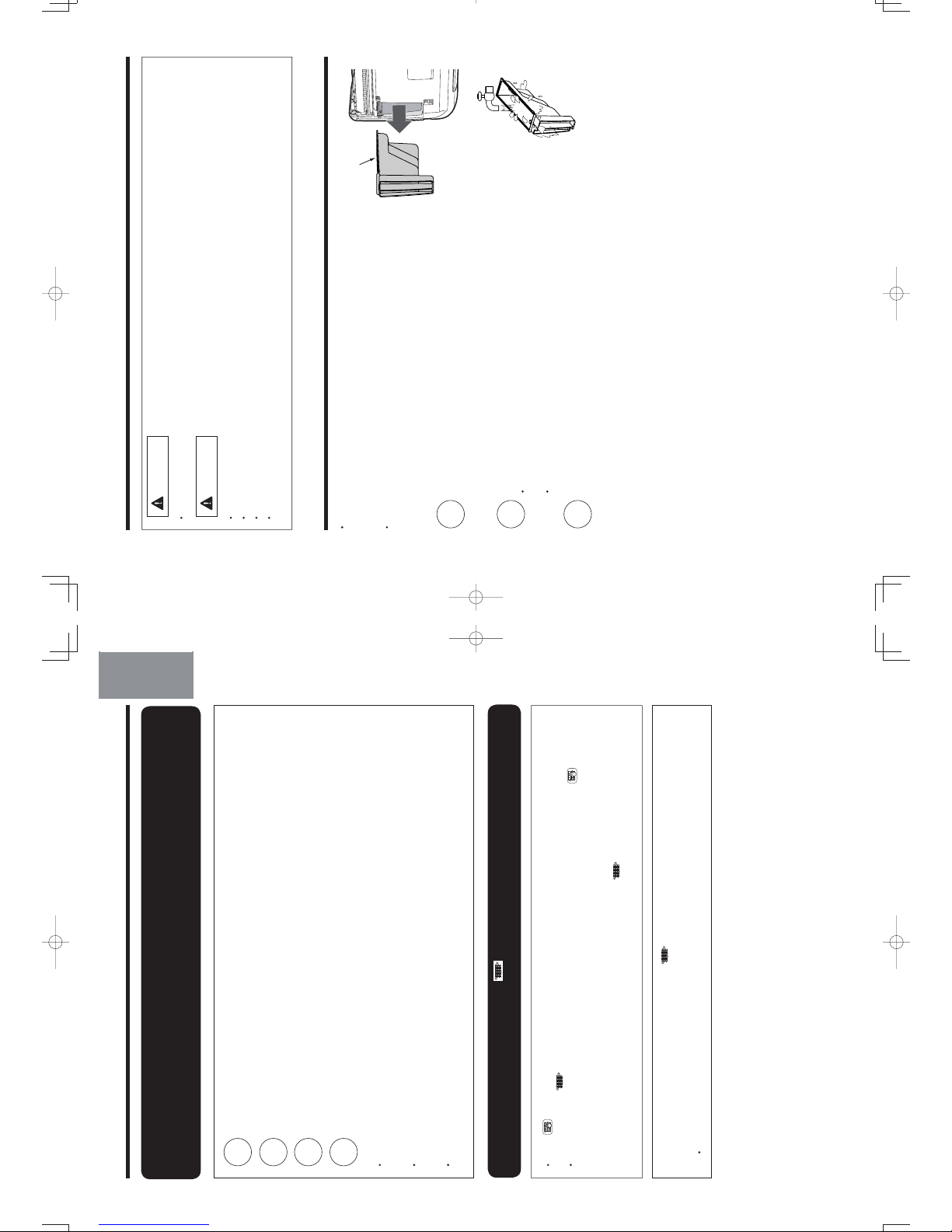
1
2
3
4
IN THE EVENT THE NOISE OF FILTER CLEANING OPERATION IS VERY OBVIOUS,
YOU CAN EXECUTE FILTER CLEANING AT THE TIME YOU PREFER BY COMBINING
“MANUAL FILTER CLEANING OPERATION” AND THE “SETTING FOR PROHIBITING
FILTER CLEANING OPERATION”
Set to prohibit the filter cleaning operation.
Return to the filter cleaning operation setting.
Operate the manual filter cleaning operation. (Page 32)
Set to prohibit the filter cleaning operation again.
(Method of setting , , , page 32)
• If the filter cleaning is performed after a long interval, dust on the micro mesh stainless filter may not be
completely cleaned just by one cycle of filter cleaning. To avoid this, frequent filter cleaning is recommended.
(Standard cleaning frequency is once every 2~3 days.)
• If the filter is not cleaned evenly at the time the filter cleaning has been completed, perform the manual filter
cleaning operation one more time after an interval of at least 5 minutes. (To protect the appliance, the filter
cleaning cannot be performed again within 5 minutes after the previous filter cleaning is completed.)
• Filter may not be cleaned evenly due to long interval of filter cleaning or due to the environment in which
the air conditioner is used. To solve this problem, clean the micro mesh stainless filter. (Page 35)
IN THE FOLLOWING CASES, THE (CLEAN) INDICATOR REPEATEDLY BLINKS,
LIGHT UP OR DIM. (IT IS NOT A MALFUNCTION)
•
If the (MANUAL CLEAN) button is pressed while the filter cleaning operation is
prohibited, a long beep
sounds and the
(CLEAN) indicator blinks. (Lit for 1 second/off for 1 second, for 10 seconds)
• To protect the appliance, the filter cleaning operation is not performed even if the
(MANUAL
CLEAN) button on the remote controller is pressed during approximately 5 minutes after filter
cleaning operation (i.e., filter cleaning operation which is performed after the air conditioner power
is turned on; automatic filter cleaning operation; and manual filter cleaning operation which is
performed using the remote controller). A long beep sounds and
(CLEAN) indicator blinks. (Lit for
1 second/off for 1 second, for 10 seconds)
The filter cleaning unit is out of order if the
(CLEAN) indicator on the indoor unit still repeatedly
on for 4 seconds/off for 1 second. In this case, filter cleaning operation is unavailable, however other
functions of the air conditioner are available without being affected.
• Contact your sales agent if the filter cleaning unit malfunction.
DEUTSCHFRANÇAISITALIANOSPANISHPORTUGUÊS
∂ППЛУИО¿
РУССКИЙ
– 33 –
ENGLISH
10_14SH3_OM.indd 33
10_14SH3_OM.indd 33
2012-2-21 14:51:52
2012-2-21 14:51:52
2
3
1
MAINTENANCE
• Before cleaning, stop unit operation with the remote controller and turn off the circuit breaker.
WARNING
•
Do not expose the unit to water as it may cause an electric shock.
•
For cleaning inside the air conditioner, consult your sales agent.
•
Avoid using detergent when cleaning the heat exchanger of the indoor unit. Unit failure may result.
•
When cleaning the heat exchanger with a vacuum cleaner, make sure to wear gloves so as not to injure your
hands on the heat exchanger fins.
CAUTION
Maintenance of dust box
• No daily maintenance is required. However, dust amount varies
depending on the environment in which the air conditioner is
used. Check the dust amount approximately once every two years
and throw the dust, if any.
• Some type of dust may be accumulated on the rear surface of the
dust catcher.
It is recommended to clean the dust catcher together with the dust box.
Dust box
Stop the operation with the remote controller and
unplug the power
supply
(or turn off the circuit breaker).
Wash the dust box with water.
• If the dirt is stubborn, wash with the dust box with warm water
below 40°C.
• After washing, dry it in the shade.
Turn on the power supply (or turn on the circuit breaker).
– 34 –
10_14SH3_OM.indd 34
10_14SH3_OM.indd 34
2012-2-21 14:51:53
2012-2-21 14:51:53
Page 24
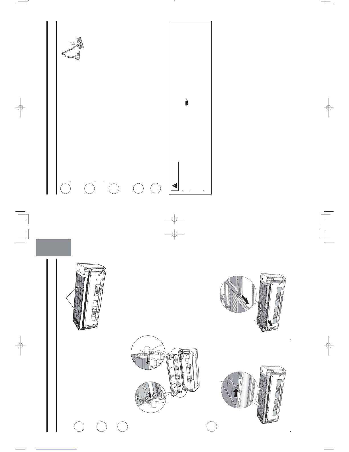
•
•
1
2
3
4
No daily maintenance is required. However, filter should be cleaned
if the dirt is noticeable due to the environment in which the air
conditioner is used.
stainless mesh filter
Stop the operation with the remote
controller and unplug the power plug
(or turn off the circuit breaker).
Open the front panel.
(Refer to page 8 on opening the front panel)
Remove the front panel.
Push
Push
Arm
Arm
Push the end of the right-side arm outward to
release the tab.
Move the left-side arm outward to release the
left tab, and then pull the panel towards you.
DEUTSCHFRANÇAISITALIANOSPANISHPORTUGUÊS
∂ППЛУИО¿
РУССКИЙ
Maintenance of Stainless Mesh Filter
Remove the front stainless mesh filter.
Filter locks
Hold this part to pull it out
Slide the left and right stainless filter locks
towards the direction as illustrated.
Slightly lift up the stainless mesh filter
and pull it out towards you.
– 35 –
ENGLISH
10_14SH3_OM.indd 35
10_14SH3_OM.indd 35
2012-2-21 14:51:54
2012-2-21 14:51:54
5
6
7
8
9
MAINTENANCE (continued)
Maintenance of mesh stainless filter (continued)
Vacuum the dust.
• In the event the stainless mesh filter is heavily dirty and the dust cannot
be cleaned with a vacuum cleaner, wash the filter with neutral detergent
and rinse well with water, and then dry the filter in the shade.
• Align the filter with the top face of the indoor unit, and then slide and push it in.
(The shape of the left and right filters is the same.)
• Tighten the left and right filter locks to the indicated direction.
Attach the front panel.
Insert the shaft of the left arm along the step on the unit into the hole.
Securely insert the shaft of the right arm along the step on the unit into the hole.
Make sure that the front panel is securely attached, and then close the front panel.
Close the front panel.
(Refer to page 9 on closing the front panel)
Turn on the power supply (or turn on the circuit breaker).
• Improper installation of the micro mesh stainless filter could result in malfunction. Filter cleaning
operation can not be performed properly and the
(CLEAN) indicator blinks.
• Do not operate the air conditioner without the micro mesh stainless filter.
Dust goes in the gap of the heat exchanger as well as inside the appliance and may cause unpleasant smell
on the heat exchanger or could result in malfunction.
• Be extra careful not to cut your hand with the fin of the heat exchanger when removing and reattaching
the micro mesh stainless filter.
CAUTION
Attach the stainless mesh filter.
– 36 –
10_14SH3_OM.indd 36
10_14SH3_OM.indd 36
2012-2-21 14:51:55
2012-2-21 14:51:55
Page 25

1
2
3
4
5
6
7
Maintenance of dust catcher
No daily maintenance is required. However, filter should be cleaned if the dirt is noticeable due to the
environment in which the air conditioner is used.
Some type of dust may not go in the dust box but be accumulated on the rear surface of the dust catcher.
It is recommended to check the dust amount on the dust catcher approximately once every 2 years and
clean the dust catcher if it is dirty.
Stop the operation with the remote controller and unplug
the power supply (or turn off the circuit breaker).
Remove the front panel.
(Refer to page 35 on removing the front panel)
Remove the dust catcher.
• Remove the dust catcher as shown with arrows.
• If dust is accumulated at the inner side of the dust catcher,
remove the dust with a vacuum cleaner.
Wash with water.
• Please wash with water.
• If the dirt is stubborn, use a mild detergent and wash with warm
water below 40°C.
• Dry completely in the shade.
Attach the dust catcher.
• Hold the dust catcher for the top face with its side having the lever
facing towards you. Insert and push in the dust catcher in the arrow
direction until it clicks.
Attach the front panel.
(Refer to page 36 on attaching the front panel)
Improper installation of the dust catcher could result in malfunction. Filter cleaning operation can not
be performed properly and the
(CLEAN) indicator blinks.
CAUTION
DEUTSCHFRANÇAISITALIANOSPANISHPORTUGUÊS
∂ППЛУИО¿
РУССКИЙ
Turn on the power supply (or turn on the circuit breaker).
– 37 –
ENGLISH
10_14SH3_OM.indd 37
10_14SH3_OM.indd 37
2012-2-21 14:51:55
2012-2-21 14:51:55
MAINTENANCE (continued)
Maintenance of Ion mist unit
Stop the operation with the remote controller
and unplug the power supply (or turn off the
circuit breaker).
Slowly open the vertical air deflectors using
both hands.
CAUTION
s Be sure to open slowly using both hands as shown
in the illustration.
Otherwise, it may cause malfunction.
s Do not use excessive force to move the air deflector
beyond the stopper located below it.
Otherwise, it may cause malfunction.
Remove the dirt on the ion mist unit
with a toothbrush.
噝 Be sure to use a dry toothbrush.
噝 Lightly brushed off the dust.
Horizontal air
deflectors
CAUTION
噝 Do not touch the r conditioner is in operation
High voltage generated at these parts could result in electrical shock.
噝 Do not splash or direct water to the ion mist unit
It may cause short circuit or malfunction.
– 38 –
Turn on the power supply.
(or turn on the circuit breaker)
ion mist unit while the ai
Ion Mist Unit
1
2
3
4
• Be s
in th
Oth
• Do
bey
Oth
10_14SH3_OM.indd 38
10_14SH3_OM.indd 38
2012-2-21 14:51:56
2012-2-21 14:51:56
Page 26
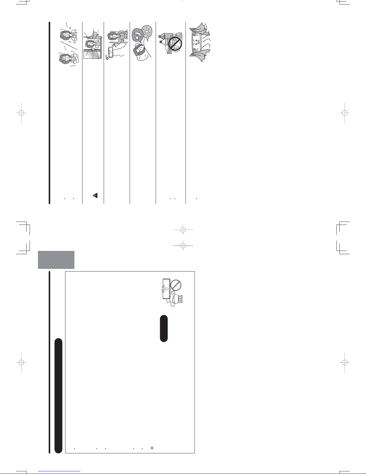
DEUTSCHFRANÇAISITALIANOSPANISHPORTUGUÊS
∂ППЛУИО¿
РУССКИЙ
UNDERSTANDING THE OPERATING MECHANISM
NAMES AND FUNCTIONS OF EACH PART (Page 4)
CAUTION
Do not use a stove or any
other high temperature
devices in proximity to
the indoor unit.
PROHIBITION
– 39 –
ENGLISH
Heating capability
• This room air conditioner utilizes a heat pump system that absorbs exterior heat and brings it into a room to
be heated. As the ambient temperature gets lower, heating capability will also lower. In such a situation, the
PAM and inverter work to increase compressor rpm to keep the unit’s heating capability from decreasing. If
the unit’s heating performance is still unsatisfactory, other heating appliances should be used to augment
this unit’s performance.
• The air conditioner is designed to heat an entire room so that it may take some time before you feel warm.
Timer operation is recommended for effective preheating ahead of the desired time. (Page 26)
• When outside temperature becomes lower while humidity remains high, condensation forms on the heat
exchanger of the outdoor unit and the heating efficiency may be affected if condensation is not removed. To
prevent this problem, the air conditioner performs condensation-removing operation automatically. At this
time, the heating operation is suspended and it usually takes approximately 5~10 minutes (maximum of 20
minutes) to resume the heating operation.
Cooling, dehumidifying and dry cool capabilities
• If the heat present in a room exceeds the unit’s cooling capacity (for example, if there are many people in
the room or other heating appliances are used), the preset room temperature may not be reached.
• The preset temperature may not be reached if a heat source or humidity which exceeds the air conditioner’s
dehumidifying ability is present in the room.
Piping which is too long could lower the heating/cooling performance.
10_14SH3_OM.indd 39
10_14SH3_OM.indd 39
2012-2-21 14:51:57
2012-2-21 14:51:57
THE IDEAL WAYS OF OPERATION
1. An average room temperature setting is probably the best for you as well
as being economical.
• Excessive cooling or heating is not recommended for health reasons. High
electricity bills may also result.
• Close the curtains or blinds to prevent heat from flowing into or escaping the
room as well as to make more effective use of electricity.
2. At intervals, the doors and windows should be opened to let fresh air in.
Make sure the room is ventilated when operating the air
conditioner at the same time as other heating appliances.
3. Make efficient use of mold monitor when going out.
(Refer to mold monitor)
4. Make efficient use of the timer before going to sleep.
(Refer to page 26~28 on using the timer)
5. The following must never be used for cleaning the indoor and outdoor
units:
• Benzine, thinner and scrub can damage plastic surfaces or coating.
• Hot water above 40°C can shrink the filter and deform plastic parts.
6. Do not block the air intake and air outlet.
• Do not block the air outlets and intakes of the indoor and outdoor units with
curtains or other obstacles which could degrade air conditioner performance
and cause unit failure.
cold
hot
CAUTION
– 40 –
10_14SH3_OM.indd 40
10_14SH3_OM.indd 40
2012-2-21 14:51:57
2012-2-21 14:51:57
Page 27
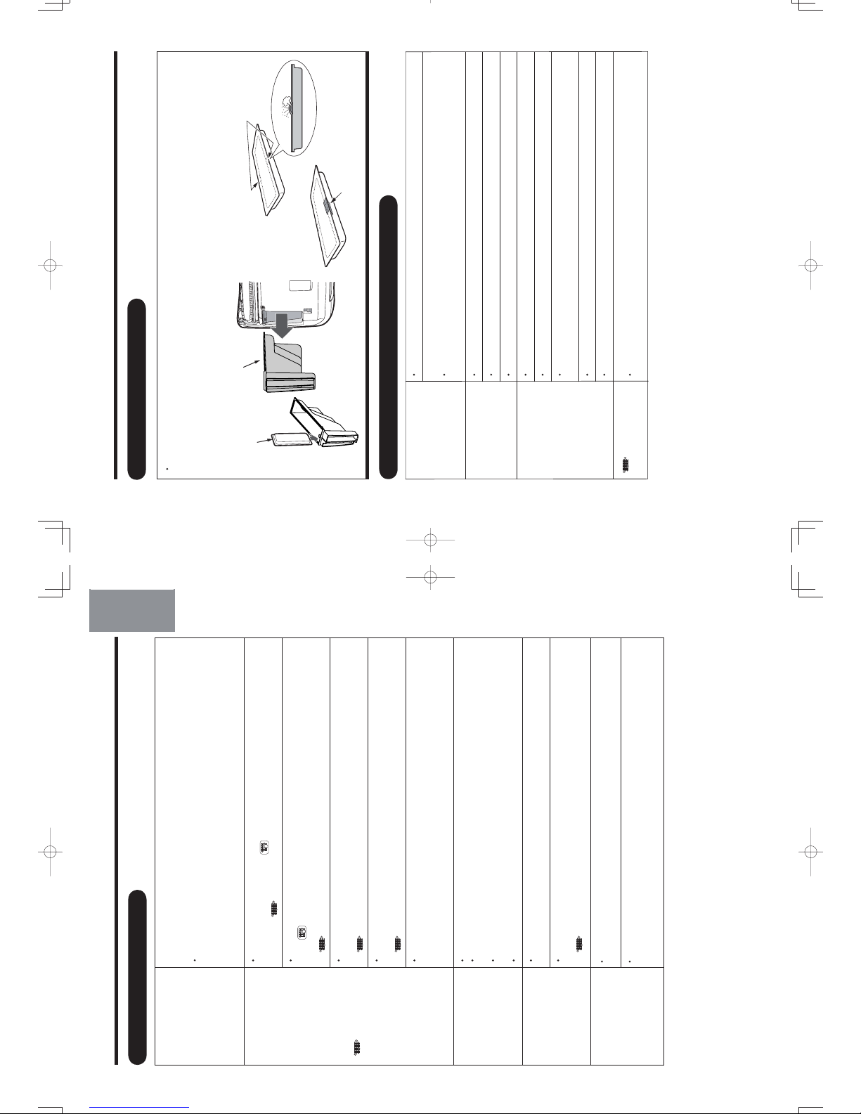
DEUTSCHFRANÇAISITALIANOSPANISHPORTUGUÊS
∂ППЛУИО¿
РУССКИЙ
• This is for filter cleaning operation check.
• In basic air-conditioner operation (cooling operation etc.), the filter cleaning operation
will not start even when the
(MANUAL CLEAN) button on the remote controller is
pressed.
( (CLEAN) indicator lit for 1 second/off for 1 second, for 10 seconds)
• During filter cleaning operation or within 5 minutes after the operation, even when
the
(MANUAL CLEAN) button on the remote controller is pressed, the filter
cleaning operation will not restart to protect the device.
( (CLEAN) indicator lit for 1 second/off for 1 second, for 10 seconds)
• Is “filter cleaning operation prohibited” being set?
Please return to the filter cleaning operation setting.
(
(CLEAN) indicator lit for second/off for 1 second, for 10 seconds)
• Are micro mesh stainless filter, dust catcher, filter cleaning wiper, wiper cover correctly
installed?
(
(CLEAN) indicator lit for 4 seconds/off for 1 second)
• Filter cleaning is not performed if the air conditioner operation is stopped by Sleep
Timer or Off Timer function. However, if the air conditioner is stopped by Sleep
Timer or Off Timer every time, filter cleaning will be performed approximately once
a week.
• A whirring motor noise is generated due to driving of the cleaning unit.
• A clapping noise is generated when the dust catcher collects the dust swept by the
cleaning unit.
• A clapping noise is generated when the dust catcher is turned over by the cleaning
unit.
• A sweeping sound is generated when the cleaning unit sweeps the dust.
• After the filter cleaning wiper maintenance, is the cleaning unit return to the right
end part using the remote controller?
• Are micro mesh stainless filter, dust catcher, filter cleaning wiper, wiper cover correctly
installed?
(
(CLEAN) indicator lit for 4 seconds/off for 1 second)
TROUBLESHOOTING
FILTER CLEANING OPERATION
Filter cleaning is
performed after
the power is
turned on (after
the plug-in or after
the circuit breaker
is switched on
after power failure)
Filter cleaning
operation does not
start
(
(CLEAN)
indicator blinks
or lit and dim
repeatedly)
Noise occurred
during filter
cleaning operation
Cleaning unit
stops halfway
• Filter may not be cleaned evenly depending on the environment in which the air
conditioner is used. To solve this problem, clean the micro mesh stainless filter.
• Depending on dust amount, the micro mesh stainless filter may not be completely
cleaned by manual filter cleaning operation performed at your preferred time while
filter cleaning operation is prohibited.
Micro mesh
stainless filter is
still dirty
– 41 –
ENGLISH
10_14SH3_OM.indd 41
10_14SH3_OM.indd 41
2012-2-21 14:51:58
2012-2-21 14:51:58
TROUBLESHOOTING (continued)
Anti-mold
wasabi cassette
Dust box
ANTI-MOLD WASABI CASSETTE
• Anti-mold elements with wasabi aroma prevents mold growth inside the dust box in which the dust collected
by filter cleaning operation is kept. Although only a trace amount of anti-mold elements is released, there may
be wasabi smell in the room depending on the environment in which the air conditioner is used. If you feel this
smell is unpleasant, block one of the anti-mold element outlets with a commercially available adhesive tape. If
this measure is taken, the amount of anti-mold element to be released will be reduced and the anti-mold effect
will also be less accordingly. To prevent mold growth, frequent cleaning of the dust box is recommended.
Outlet (2 places)
The gap made on
the side surface
Block one of the outlets with an
adhesive tape (Either one of 2
outlets)
• Do the batteries need replacement?
• Is the polarity of the inserted batteries correct?
• Is the power plug inserted properly?
• Is the fuse blown out or circuit breaker tripped?
• Is there a blackout? (Operation remains idle after a blackout.)
• Is the micro mesh stainless filter blocked with dust?
• Is the set temperature suitable?
• Have the vertical air deflector been adjusted to the correct positions according to
the operation mode selected?
• Are the air inlets and air outlets of indoor and outdoor units blocked?
• Is the fan speed “LOW” or “SILENT”?
•
Check “filter cleaning operation”.
PLEASE CHECK THE FOLLOWING BEFORE SERVICE
Signal cannot be
received
(Remote controller
display is dim or
blank)
Operation does
not start
Does not cool well
Does not heat well
(CLEAN)
indicator blinks
– 42 –
10_14SH3_OM.indd 42
10_14SH3_OM.indd 42
2012-2-21 14:51:58
2012-2-21 14:51:58
Page 28
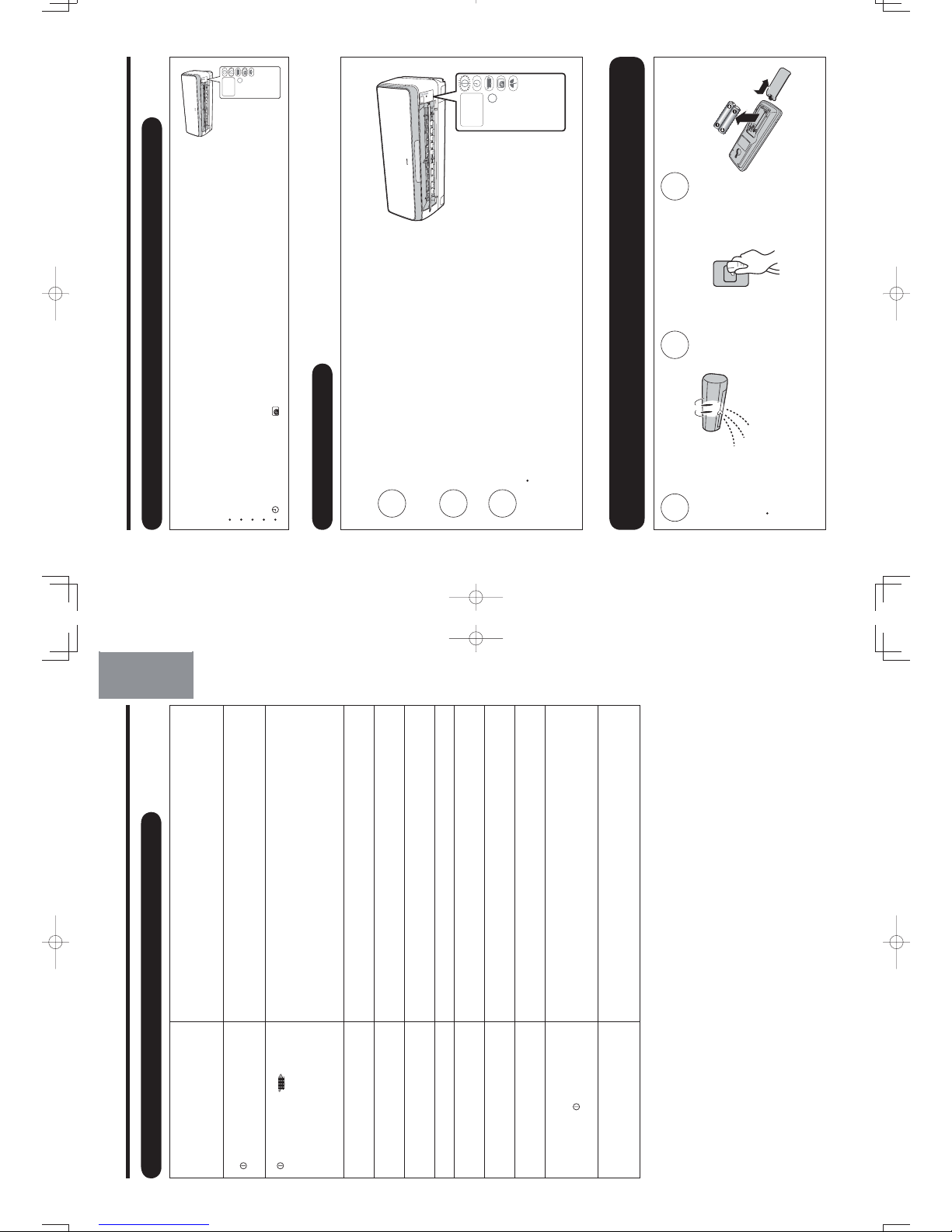
Except for anti-mold wasabi cassette, no smell-generating material or
substance is used for air conditioner. This is due to the smell or odor, such
as cigarette, cosmetics and food, present in the room that is sucked in
and then blown out by the air conditioner.
Indicates preheating or defrosting operation is underway.
Indicates internal cleaning operation is underway. (Page 21)
Refrigerant flow noise in the pipe or valve sound generated when flow
rate is adjusted.
Noise generated when the unit expands or contracts due to temperature
changes.
Noise generated with the indoor unit fan’s rpm changing such as operation
start times.
Noise of the motorized valve when the unit is switched on.
Operation noise changes due to power variations according to room
temperature changes.
Mist is generated as the air within the room is suddenly cooled by
conditioned air.
Water generated during defrosting operation evaporates and steam is
emitted.
Auto fresh defrosting is activated (as the heating operation is stopped, the
microcomputer checks frost accumulated in the indoor unit and instructs
the unit to perform automatic defrosting if necessary).
Depending on the number of person in the room and the conditions of
the room, actual room temperature may deviate slightly from the remote
controller’s setting.
THE FOLLOWING CASES DOES NOT INDICATE MALFUNCTION
TROUBLESHOOTING (continued)
Odors
In heating operation,
(OPERATION) indicator lit
and dim repeatedly
(OPERATION),
(CLEAN), indicators lit after
the operations of cooling,
dehumidifying and dry cool
Hissing or fizzy sound
Squeaking noise
Rustling sound
Clicking sound
Operation sound changes
Mist emission
Steam emitted from outdoor unit
Outdoor unit continues to
operate even if operation is
stopped and
(OPERATION)
indicator blinks
Preset temperature cannot be
reached
DEUTSCHFRANÇAISITALIANOSPANISHPORTUGUÊS
∂ППЛУИО¿
РУССКИЙ
– 43 –
ENGLISH
10_14SH3_OM.indd 43
10_14SH3_OM.indd 43
2012-2-21 14:51:58
2012-2-21 14:51:58
CONTACT YOUR SALES AGENT IMMEDIATELY ON FOLLOWING CASES
In the event that any trouble or phenomenon listed below still occurs even after a
check has been conducted according to the troubleshooting procedures on page
41~44 , disconnect the power plug from the outlet (or switch off the circuit breaker)
and immediately contact your sales agent.
• The circuit breaker switches off or the fuse blows frequently.
• The switch operation is not stable.
• Foreign matter or water accidentally enters the unit interior.
• The power cord gets excessively hot or its insulation is torn or stripped.
•
(TIMER) indicator or (MONITOR) indicator on the indoor unit display blinks.
TEMPORARY OPERATION
Press the temporary switch to start temporary operation if the remote controller cannot function due
to dead batteries.
1
Disconnect the power supply.
(Or turn off the circuit breaker.)
2
3
Automatic operation starts when the temporary switch
is pressed.
• The air conditioner performs force-cooling operation if the temporary
switch is pressed for at least 5 seconds. This operation is allowed to
sales agents only. Users must not perform this operation.
Reconnect the power supply.
(Or turn on the circuit breaker.)
IF THE UNIT WOULD NOT BE USED FOR A LONG PERIOD OF TIME (MORE THAN
1 MONTH), PLEASE FOLLOW THE STEPS BELOW FOR MAINTENANCE
• On a sunny
day, perform stainless plasm
a air
purifying (Fan) operation for approximately
one half day. Mold can easily grow if air
conditioner is not used for a long period of
time while its inside is left wet.
1
Dry the interior of
the indoor unit.
2
Unplug the power
plug or turn off the
circuit breaker.
3
Remove the
batteries from the
remote controller.
TROUBLESHOOTING (continued)
7(0325$5<
6:,7&+
7(0325$5<
6:,7&+
– 44 –
10_14SH3_OM.indd 44
10_14SH3_OM.indd 44
2012-2-21 14:51:59
2012-2-21 14:51:59
Page 29
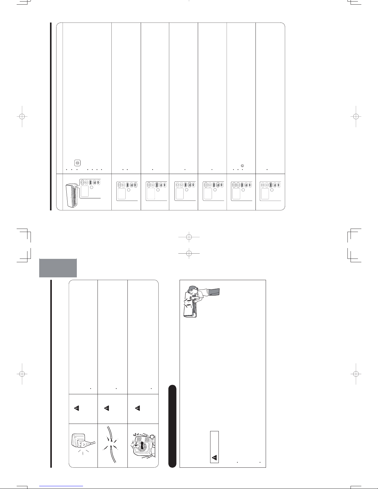
REGULAR INSPECTION
PLEASE CHECK THE FOLLOWING POINTS EVERY EITHER HALF YEARLY OR YEARLY. CONTACT YOUR
SALES AGENT SHOULD YOU NEED ANY HELP.
WARNING
Is the plug plugged into the socket firmly?
If the earth line is disconnected or faulty, unit failure or
electric shock hazard may result.
• If the plug have dust or dirt, please clean it before plug in.
WARNING
Is the unit’s earth line connected correctly?
Please make sure earth line is connected correctly.
•
If the earth line is disconnected or faulty, it may result in
malfunction or electric shock.
WARNING
Is the mounting frame stable?
Check to see if the mounting frame has rusted excessively
or if the outdoor unit has tilted or become unstable.
• If the outdoor unit collapsed or fell, it could cause injury.
INSPECTION AND MAINTENANCE
Air conditioner is designed to perform automatic filter cleaning to maintain
the interior of air conditioner clean. However, the interior of air conditioner
may get dirty and the air conditioning performance may be lowered after air
conditioner is used for a few seasons.
Beside maintenance, please perform inspection as well
Dust deposited inside the indoor unit may block the drainage path of dehumidified water and could result in
water dripping.
•
Maintenance inspection is recommended in addition to ordinary cleaning.
Request your sales agent for maintenance inspection
Maintenance inspection requires technical expertise. Use of commercially available cleaning agent may cause
crack on resin part and clogging of drainage path, which could result in water dripping and electrical shock.
• Consult your sales agent for inspection and maintenance.
CAUTION
DEUTSCHFRANÇAISITALIANOSPANISHPORTUGUÊS
∂ППЛУИО¿
РУССКИЙ
– 45 –
ENGLISH
10_14SH3_OM.indd 45
10_14SH3_OM.indd 45
2012-2-21 14:51:59
2012-2-21 14:51:59
OPERATION DISPLAY CHART
Operation mode Display
•
•
•
• Cooling operation (page 15)
operation (page 14)
•
Automatic operation (page 13)
Heating operation (page 14)
(DEHUMIDIFY) (Auto dehumidifying, condensation control, Quick laundry)
• Stainless plasma air purifying operation (page 18)
Dry cool operation (page 16)
• Combined operation of automatic, manual, heating, dehumidifying, cooling, dry cool
operations and Stainless air cleaning operation (page 18)
Infrared human presence detection (page 19)
Dynamic air deflection (tracing/evasion) (page 20)
• During internal cleaning operation (page 21)
• During preset of the mold monitor operation (page 23)
• During mold monitor operation (page 23)
• Filter cleaning operation (page 30)
• Timer preset operation (page 26)
• Sleep timer operation (page 29)
•
7(0325$5<
6:,7&+
7(0325$5<
6:,7&+
7(0325$5<
6:,7&+
7(0325$5<
6:,7&+
7(0325$5<
6:,7&+
7(0325$5<
6:,7&+
•
(TIMER) indicator lit if timer preset is set in every operations.
– 46 –
7(0325$5<
6:,7&+
10_14SH3_OM.indd 46
10_14SH3_OM.indd 46
2012-2-21 14:52:00
2012-2-21 14:52:00
•
Page 30
MEMO
DEUTSCHFRANÇAISITALIANOSPANISHPORTUGUÊS
∂ППЛУИО¿
РУССКИЙ
– 47 –
ENGLISH
10_14SH3_OM.indd 47
10_14SH3_OM.indd 47
2012-2-21 14:52:00
2012-2-21 14:52:00
< 4647D : A >
10_14SH3_OM.indd 48
10_14SH3_OM.indd 48
2012-2-21 14:52:00
2012-2-21 14:52:00
Page 31

OUTDOOR UNIT
INDOOR UNIT
– 1 –
Instruction manual
Page 1~48
To obtain the best performance and ensure years of trouble free use, please read this instruction manual completely.
SPLIT TYPE AIR CONDITIONER
INDOOR UNIT/OUTDOOR UNIT
MODEL
ENGLISH
DEUTSCHFRANÇAISITALIANOSPANISHPORTUGUÊS
∂ППЛУИО¿
«®¬¬¥£¤
RAS-1 SH3
RAS-18SH3/RAC-18SH3
8
RAC-1 SH
8
Для достижения наивысшей производительности и обеспечения длительной безаварийной
внимательно изучите данную инструкцию .
Инструкция по эксплуатации
стр.
49 ~9 6
работы
3
18SH3_OM.indd 1
18SH3_OM.indd 1
2012-2-21 14:45:19
2012-2-21 14:45:19
• Please read the “Safety Precaution” carefully before operating the unit to ensure correct usage of the unit.
• Pay special attention to signs of “
Warning” and “ Caution”. The “Warning” section contains matters which, if
not observed strictly, may cause death or serious injury. The “Caution” section contains matters which may result
in serious consequences if not observed properly. Please observe all instructions strictly to ensure safety.
• The signs indicate the following meanings. (The following are examples of signs.)
• Please keep this manual after reading.
PRECAUTIONS DURING OPERATION
WARNING
WARNING
SAFETY PRECAUTION
• Do not reconstruct the unit.
Water leakage, fault, short circuit or fi re may occur if you reconstruct the unit by
yourself.
• Please ask your sales agent or qualified technician for the installation of your unit.
Water leakage, short circuit or fire may occur if you install the unit by yourself.
• Please use earth line.
Do not place the earth line near water or gas pipes, lightning-conductor, or the
earth line of telephone. Improper installation of earth line may cause electric
shock or fire.
• Be sure to use the specifi ed piping set for R410A. Otherwise, this may result in
broken copper pipes or faults.
• A circuit breaker should be installed depending on the mounting site of the unit.
Without a circuit breaker, the danger of electric shock exists.
• Do not install the unit near a location where there is fl ammable gas. The outdoor
unit may catch fi re if fl ammable gas leaks around it. Piping shall be suitable
supported with a maximum spacing of 1m between the supports.
• Please ensure smooth fl ow of water when installing the drain hose.
• Make sure that a single phase 220V power source is used.
The use of other power sources may cause electrical components to overheat
and lead to fi re.
PRECAUTIONS DURING INSTALLATION
PROHIBITION
CONNECT EARTH LINE
PROHIBITION
WARNING
CAUTION
•
• Should abnormal situation arise (like burning smell), please stop operating the
unit and remove plug from the socket. Contact your agent. Fault, short circuit or
fi re may occur if you continue to operate the unit under abnormal situation.
• Please contact your agent for maintenance. Improper self maintenance may cause electric
shock and fi re.
• Please contact your agent if you need to remove and reinstall the unit. Electric shock or fi re
may occur if you remove and reinstall the unit yourself improperly.
PRECAUTIONS DURING SHIFTING OR MAINTENANCE
• Do not use any conductor as fuse wire, this could cause fatal accident.
• During thunder storm, disconnect the plug top and turn off the circuit
breaker.
• Do not put objects like thin rods into the panel of blower and suction side
because the high-speed fan inside may cause danger.
• Spray cans and other combustibles should not be located within a meter of the
air outlets of both indoor and outdoor units.
As a spray can’s internal pressure can be increased by hot air, a rupture may result.
PROHIBITION
PROHIBITION
PROHIBITION
PROHIBITION
“OFF”
“OFF”
This sign in the fi gure indicates prohibition. Indicates the instructions that must be followed.
PROHIBITION
– 2 –
Avoid an extended period of direct airflow for your health.
18SH3_OM.indd 2
18SH3_OM.indd 2
2012-2-21 14:45:19
2012-2-21 14:45:19
Page 32

• Do not place plants directly under the airfl ow as it is bad for the plants.
• Do not direct the cool air coming out from the air-conditioner panel to face
household heating apparatus as this may affect the working of apparatus such
as the electric kettle, oven etc.
• The product shall be operated under the manufacturer specifi cation and not
for any other intended use.
PRECAUTIONS DURING OPERATION
CAUTION
• Do not attempt to operate the unit with wet hands, this could cause fatal
accident.
• When operating the unit with burning equipments, regularly ventilate
the room to avoid oxygen insuffi ciency.
• Please ensure that outdoor mounting frame is always stable, fi rm and without
defect. If not, the outdoor unit may collapse and cause danger.
• Do not wash the unit with water or place a water container such as a vase on
the indoor unit.
Electrical leakage could be present and cause electric shock.
• Be sure to stop the operation by using the remote controller and turn off the
circuit breaker during cleaning, the high-speed fan inside the unit may cause
danger.
• Turn off the circuit breaker if the unit is not be operated for a long period.
• Do not climb on the outdoor unit or put objects on it.
• When operating the unit with the door and windows opened, (the room
humidity is always above 80%) and with the air defl ector facing down or moving
automatically for a long period of time, water will condense on the air deflector
and drips down occasionally. This will wet your furniture. Therefore, do not
operate under such condition for a long time.
• If the amount of heat in the room is above the cooling or heating capability of
the unit (for example: more people entering the room, using heating equipments
and etc.), the preset room temperature cannot be achieved.
• Indoor unit cleaning must be performed by authorized personnel only. Consult
This appliance is not intended for use by young children or infirm persons unless they have been
Young children should be supervised to ensure that they do not play with the appliance.
your sales agent.
adequately supervised by a responsible person to ensure that they can use this appliance safely.
Using a commercially available detergent or similar can damage the plastic parts
or clog the drain pipe, causing water to drip with potential electric shock hazard.
• Do not touch the air outlet, bottom surface and aluminium fi n of the outdoor
unit.
You may get hurt.
Do not touch the refrigerant pipe and connecting valve.
Burns may result.
PROHIBITION
DON’T WET
PROHIBITION
PROHIBITION
PROHIBITION
DON’T TOUCH
“OFF”
PROHIBITION
PROHIBITION
PROHIBITION
PROHIBITION
PROHIBITION
DON’T TOUCH
STRICTLY OBSERVE
PRECAUTIONS
“OFF”
DEUTSCHFRANÇAISITALIANOSPANISHPORTUGUÊS
∂ППЛУИО¿
РУССКИЙ
– 3 –
ENGLISH
•
•
•
18SH3_OM.indd 3
18SH3_OM.indd 3
2012-2-21 14:45:20
2012-2-21 14:45:20
Drain Port (bottom)
Air Outlet
Discharges cool air when in heating
mode and warm air when in cooling
and dry cool modes, and warm or
cold air when in the dehumidifying
mode.
NAMES AND FUNCTIONS OF EACH PART
INDOOR UNIT
OUTDOOR UNIT
Signal Receiver
(internal)
Receive signal from the
remote control.
Indicator
Front Panel
(Page 8)
Horizontal/
Vertical Air Deflector
(internal)
Air Outlet
Remote Controller
Pipe/Wiring
Drain Hose
Drains dehumidified water generated from the indoor unit when in
the cooling, dehumidifying and dry cool modes.
Air Inlet (rear and left side)
噝 Even if the operation is stopped, the outdoor
unit fan continues to rotate for 10~60 seconds
to cool down the electrical parts.
噝 In heating operation, condensed water and
defrosted water is discharged from the outdoor
unit. Do not block the drain port as the water in
the drain may freeze in a cold area.
噝 Even during cooling operation, the water
condensed in the pipe, etc. may flow out from
the outdoor unit.
噝 When installing the outdoor unit under eaves,
etc. of the apartment, install a bush and drain
pipe on the drain port for drainage treatment.
ABOUT OUTDOOR UNIT
(Understanding The Operating Mechanism, page 39)
Earth Terminal
(side bottom)
噝 While the power is on, a very small amount of power is
consumed within the control circuit even when the unit
is not in operation.
Power can be saved if the circuit breaker is switched off.
CAUTION
Pull out the power plug if the unit is not in
use for a long period.
(Or turn off the circuit breaker.)
Infrared
Dynamic Air Deflection Sensor
Temporary Operation Switch
(Forced Cooling Switch)
When the remote
controller does not
work due to factors
like dead batteries,
you can press the
temporary operation
switch to start
temporary
operation. (Page 44)
– 4 –
Ion Mist Unit
18SH3_OM.indd 4
18SH3_OM.indd 4
2012-2-21 14:45:20
2012-2-21 14:45:20
Page 33

Air Cleaning Mesh Box
DEUTSCHFRANÇAISITALIANOSPANISHPORTUGUÊS
∂ППЛУИО¿
РУССКИЙ
Replace the air cleaning mesh box.
Dž“Make sure that it clicks into place.”
Dž“If it dose not click into place, abnormal sounds
may be heard or the box may fall off.”
Close the front panel.
Ą
INDOOR UNIT CONTROL PANEL / CLEANING UNIT
Open the front panel to operate. (How to open the front panel, page 8)
Dust Catcher
Collects the dust swept by
the cleaning unit. (At front
and top.) (Page 37)
Dust Box
Collects and keeps the dust
that has been cleaned.
(Page 34)
Stainless Mesh Filter
(inside)
Collects particulates and dusts in the air. (Page 35)
Air Cleaning Mesh Box
Preparation
Stop the air conditioner, and disconnect
the power supply (or turn off the circuit breaker).
Open the front panel.
Pull out the air cleaning mesh box as illustrated to
remove it.
Insert the air cleaning mesh into the slot as illustrated.
Connect the power cord (or turn on the circuit breaker).
Jaw
With the air cleaning mesh used, the air-conditioning capability will fall slightly.
Remove dust from the surface with a vacuum cleaner, and DO NOT clean it with water.
(We recommend you clean it once every 6 months and replace it once every 2 years.)
– 5 –
ENGLISH
Cleaning Unit
Cleans the dust
caught by the
stainless mesh
filter.
Wasabi-Nano Titanium Air Cleaning Mesh
How to Attach the Wasabi-Nano Titanium Air Cleaning Mesh
18SH3_OM.indd 5
18SH3_OM.indd 5
2012-2-21 14:45:21
2012-2-21 14:45:21
Transmission Indicator
The transmission indicator
ROOM TEMPERATURE
Button
Press this button to set the
room temperature. Keep
pressing and the value will
change more quickly.
STOP Button
HEAT Button
Press this button to start
heating operation.
(Page 14)
DEHUMIDIFY Button
Press this button to start
dehumidifying operation.
(Page 14)
COOL Button
Press this button to start
cooling operation.
(Page 15)
DRY COOL Button
Press this button to start dry
cool operation. (Page 16)
AUTO Button
Press this button to
start automatic operation.
(Page 13)
BUTTONS TO
START OPERATIONS
Remote controller can be used when it is fixed on a wall or pillar using the remote controller holder.
Before fixing it, make sure the indoor unit can be controlled from the remote controller fixing point.
SLEEP TIMER Operation Button
Press this button to start sleep timer
operation. (Page 29)
REMOTE CONTROLLER
Transmits the operation and timer settings to the indoor unit.
The LCD shown in the illustration below is the display immediately after the reset switch is pressed. Usually not
all the data are displayed. On the LCD shown below, the functions not available for this room air conditioner are
also displayed.
NAMES AND FUNCTIONS OF EACH PART (continued)
Transmission Part
HUMIDITY Button
Press this button to set the
humidity for dehumidify and
dry cool operations.
Screw
INFRARED HUMAN-PRESENCE
SENSING Button
Press this button to enter
the dynamic air deflection mode.
(Page 19, 20)
Press this button to start I on mist
operation.
– 6 –
Press this button to stop any
operation except the preset timer.
lit when a signal is sent.
ION MIST Button
(Page
18)
18SH3_OM.indd 6
18SH3_OM.indd 6
2012-2-21 14:45:22
2012-2-21 14:45:22
Page 34

These are preset functions
except for
(SAVE).
Preset can be done if these
buttons are pressed while the
air conditioner is stopped,
however, the unit will not
function accordingly.
FUNCTION SELECTOR
Buttons
Each time when you press,
blinking changes in the
following sequence (page 12,
21, 22, 23):
ON/OFF Button
Use this button to set or cancel
the function selected by the
function selector.
FUNCTION SELECTOR
(When the door is open)
MANUAL CLEAN Button
Starts filter cleaning operation
while the air conditioner
operation is stopped. (Page 32)
FAN SPEED Button
VERTICAL AIRFLOW Button
Use this button to swing the
vertical air deflector or to adjust
the angle to your preference.
(Page 24)
HORIZONTAL AIRFLOW
Button
Use this button to swing the
horizontal air deflector or
to adjust the angle to your
preference. (Page 25)
SET TIME Button
Use this button to set and
check the current time.
(Page 11)
TIMER Buttons
RESET Button
Press this button after the
batteries are replaced and
when the air conditioner does
not function properly. (Page 11)
DEUTSCHFRANÇAISITALIANOSPANISHPORTUGUÊS
∂ППЛУИО¿
РУССКИЙ
POWERFULL Button
Press this button to start
powerful operation. (Page 18)
MANUAL/AUTO Button
Press this button to switch
between auto/manual
dehumidifying and dry
cool operation. (Page 17)
DYNAMIC AIR DEFLECTION
Button
Press this button to start
dynamic air operation.
(Page 20)
– 7 –
ENGLISH
Press this button to
select fan speed.
Four options are available:
Auto, H i, M ed,L ow,and Silent.
18SH3_OM.indd 7
18SH3_OM.indd 7
2012-2-21 14:45:22
2012-2-21 14:45:22
•
2
•
Take out the anti-mold wasabi
cassette from the aluminium bag.
Do not remove or tear
the aluminium sheet on
the surface nor make a
hole on it.
•
Remove the dust box housing
Dust Box Housing
Dust Box Housing
Handle
INSTALLING ANTI-MOLD WASABI CASSETTE
Open the front panel.
•
Do not hold the movable panel
when opening and closing the
front panel.
Front panel
Gripping part
Gripping part
Panel support
•
Hold and lift up the front panel.
•
Push up the panel support until it
clicks to lock it.
Lower the front panel and fix in
position with the panel support.
Install the anti-mold wasabi cassette.
Aluminium bag
Slide the anti-mold
wasabi cassette that
has been taken out of
the wrapper directly
into the Dust Box
Housing.
CAUTION
• Do not put your face close to the package when
you open it.
Your eyes or nose may be irritated by wasabi aroma.
• Do NOT eat.
1
No daily maintenance is required. However,
the effectiveness of anti-mold wasabi cassette
will be lost after approximately 10 years have
elapsed. Replace the anti-mold wasabi cassette
in such event.
この中に「防カビわさびカセット」が入っています
●製品の取扱説明書を確認して確実に取り付けてください。
●開封時は顔を近づけないでください。
わさびの香り成分で、目や鼻に刺激を感じることがあります。
●「防カビわさびカセット」の表面のアルミシートを
はがしたり、破ったり、穴をあけたりしないでください。
「防カビわさびカセット」の効果がなくなります。
●食べられません。
注
意
CAUTION
•
Do not open the front panel during operation
.
It may interrupt the movable panel to work properly.
Be sure to stop
the operation first before opening
the front panel.
Anti-mold wasabi
cassette
– 8 –
18SH3_OM.indd 8
18SH3_OM.indd 8
2012-2-21 14:45:23
2012-2-21 14:45:23
Page 35

DEUTSCH
DEUTSCHFRANÇAISITALIANOSPANISHPORTUGUÊS
∂ППЛУИО¿
РУССКИЙ
Close the front panel.
•
Hold and lift up the front panel.
CAUTION
• If the front panel is loose, it may come off and drop.
• When opening the front panel upwards, please do not use excessive force.
If the front panel comes off the device, this may cause it to malfunction.
• When the front panel remains open, be sure to push up the panel
support.
•
Push down the panel support until it clicks.
Push the both ends of the front panel first and
then its center until it clicks.
•
Pull it downward.
3
– 9 –
ENGLISH
18SH3_OM.indd 9
18SH3_OM.indd 9
2012-2-21 14:45:24
2012-2-21 14:45:24
FILTER CLEANING UNIT OPERATION CHECK
Make sure the power plug is firmly plugged into the power outlet.
WARNING
• Be sure to use the power outlet exclusively for
air conditioner
Use of other power outlet may cause heat, which
could result in fire.
• Make sure that dust is not deposited on the
power plug and be sure to plug in until the blades
of the plug are fully inserted to avoid unstable
plug-in and dust from being accumulated
Use of air conditioner with dusty power plug or
improper power connection could result in electrical
shock or fire.
CAUTION
Do not operate with
wet hands
It may cause electric
shock.
Compulsory
Wet Hand
Prohibited
Performing operation check after the power is turned on.
Perform the filter cleaning unit operation check
• After the power is turned on (after the power plug is inserted into the power
outlet or after the circuit breaker is switched on after power failure), the
cleaning unit makes one cycle of back and forth movement.
• At this time, the
(CLEAN) indicator is lit.
• One cycle of operation check will take approximately 5 minutes.
• During the operation check, the unit performs “Fan” operation while the movable
panel and horizontal air deflector remain closed.
• If the
(CLEAN) indicator blinks (lit for 4 seconds/off 1 second) after the
operation check, refer to “Troubleshooting” on page 44.
Cleaning Unit
There is a filter cleaning wiper inside.
Dust catcher
CAUTION
Do not put your fingers or a stick etc into the top surface during
the filter cleaning operation
It may result in injury or malfunction.
• The illustration shows the unit without front
panel for your reference only.
1
2
Compulsory
7(0325$5<
6:,7&+
– 10 –
18SH3_OM.indd 10
18SH3_OM.indd 10
2012-2-21 14:45:25
2012-2-21 14:45:25
Page 36

DEUTSCHFRANÇAISITALIANOSPANISHPORTUGUÊS
∂ППЛУИО¿
РУССКИЙ
DEUTSCH
Address
Address
PREPARE THE REMOTE CONTROLLER
Install the batteries.
• Use two AAA-size batteries.
Set the current time (Ex: set to 1:30 p.m.)
RESET
1
2
Press the (TIMER) button to adjust to the current time.
• You can fast forward the time by continuously pressing the
button.
Confirm the current time
• Press the
(SET TIME) button to check the current time
(The time display disappears 3 minutes later). If necessary,
readjust the time following the above procedure 1 and 2.
• Address selector switch is used to prevent
remote controller signal interference in such
circumstance where 2 indoor units are used in
the same room. This switch is not usually used.
(The factory setting is at “A” side.)
For this setting, please make an inquiry to your
sales agent.
Address selector
switch
Switch lever
Remote controller
backside
Do not operate by yourself.
Push mark
and pull.
ABOUT ADDRESS SELECTOR SWITCH
Time is incremented
Time is decremented
Press
(SET TIME) button to set the current time.
• “AM” or “PM” is lit instead of
blinking. It automatically goes
off in 10 seconds.
1
2
Open the cover and press the RESET
button with a sharp tip item.
3
• 18:88 lights up on the current
time display and “AM” and
“PM” start blinking.
CAUTION
1. Do not mix new and old batteries, or
different type of batteries together.
2. Remove the batteries when you do
not use the remote controller for 2 or 3
months.
DEUTSCH
– 11 –
ENGLISH
18SH3_OM.indd 11
18SH3_OM.indd 11
2012-2-21 14:45:25
2012-2-21 14:45:25
1
While (SAVE) is blinking, point the remote controller towards
the unit and press the (ON/OFF) button.
• A short beep sounds and
(SAVE) indicator turns on.
Press the (FUNCTION SELECTOR)
button until
(SAVE) blinks.
Press the (FUNCTION SELECTOR) button again until
(SAVE) blinks.
While
(SAVE) is blinking, point the remote controller towards
the unit and press the (ON/OFF) button.
• A short beep sounds and
(SAVE) indicator turns off, indicates
the setting is released.
Notes for “save” setting
• If ampere is set to “Save”, the maximum heating capacity slightly lowers
and starting up of heating operation will take a little longer. Besides,
the preset temperature may not be reached if outside temperature is
low.
• Point the remote controller to the signal receiver of the unit
Signal reception distance is approximately 7m in front of the unit.
However, this distance may be shorter or the signal may not be
receivable if there is an electronic lighting device in the same room.
• Handle the remote controller with care
Dropping it or getting it wet may compromise its signal transmission
capability. After new batteries are inserted into the remote controller,
the unit require approximately 10 seconds before it can respond to
commands and begin operation.
WHEN OPERATING THE REMOTE CONTROLLER
Approximately
7m from the front
PREPARE THE REMOTE CONTROLLER (continued)
Ampere setting (Standard/Save) can be selected.
If you experience frequent circuit breaker tripping, set ampere to “Save” to avoid this problem.
(Ampere is set to “Standard” at the time of purchase.)
4
2
RELEASE
– 12 –
18SH3_OM.indd 12
18SH3_OM.indd 12
2012-2-21 14:45:26
2012-2-21 14:45:26
Page 37

SPANISHPORTUGUÊS
∂ППЛУИО¿
РУССКИЙ
AUTOMATIC OPERATION
•
•
•
nj
1
2
2
1
7(0325$5<
6:,7&+
Based on the room temperature and outside temperature, the unit determines the most suitable operation
mode (heating, dehumidifying or cooling) and a comfortable temperature. (Set the current time on the remote
controller before starting operation.)
Press the (AUTOMATIC OPERATION) button
to set the operation mode to auto.
•
Every time you press it, the mode will change as
shown in the chart on the right.
Press the (STOP) button.
Press the (STOP) button again.
A short beep sounds and the automatic
operation stops.
Operation mode will be displayed on the
remote controller display.
Increase
Decrease
Adjust the room temperature
Press the (ROOM TEMPERATURE)
button.
• Every time you press it, a short beep sounds and the
temperature will change by 1°C.
•
is displayed if the temperature is set higher than
the automatically set room temperature by 1°C.
is displayed if the temperature is set lower than the
automatically set room temperature by 1°C.
• The adjustable temperature range is not higher or lower
than 3°C of the automatically set room temperature.
• Humidity setting cannot be adjusted.
Select the fan speed
Press the (FAN SPEED) button.
• “AUTO”, “LOW” and “SILENT”
can be selected.
• Every time you press it, the
mode will change as shown in
the chart on the right.
Beep
STOP
• Performs heating operation when the room temperature is below 23°C.
Set the temperature to be around 23°C.
• Performs dehumidifying operation when the room temperature is 23~26°C.
The preset temperature will be the room temperature at the time of start of air conditioner
operation.
• Performs cooling operation when the room temperature is above 27°C.
Set the temperature to be around 27°C.
Room temperature and fan speed can be adjusted to your preference.
AUTOMATIC OPERATION
Heating
Dehumidifying
Cooling
Even if dehumidifying operation is set, the air conditioner may not execute dehumidifying if the room humidity
is not very high. This is not a malfunction.
DEUTSCHFRANÇAISITALIANOSPANISHPORTUGUÊS
∂ППЛУИО¿
РУССКИЙ
– 13 –
ENGLISH
18SH3_OM.indd 13
18SH3_OM.indd 13
2012-2-21 14:45:27
2012-2-21 14:45:27
•
•
•
HEATING OPERATION
Press the (HEAT) button to start heating operation.
Press the (HEAT) button.
• Adjust the room temperature and fan speed to your preference.
Temperature range between 16°C~32°C can be set.
Press the (STOP) button.
A short beep sounds and heating operation stops.
STOP
DEHUMIDIFYING OPERATION
3 types of dehumidifying operations can be performed by pressing the (DEHUMIDIFY) button.
Performs powerful dry operation without lower down the room temperature.
Press the (DEHUMIDIFY) button.
• Every time you press the (DEHUMIDIFY) button,
the mode will change as shown in the chart below.
Condensation
Control
Auto
Dehumidifying
Quick
Laundry
(“AUTO” flashes for 5 seconds)
•
In auto dehumidifying mode, fine adjustment of room temperature, humidity
adjustment and fan speed selection can be made to your preference.
Every time you press the ROOM TEMPERATURE button, the temperature will change
by 1°C. (Temperature setting range is not higher or lower than 3°C.) Every time
you press the HUMIDITY button, the humidity will change by 5%. (Humidity setting
range is 40%~70%.)
• In quick laundry mode, fine adjustment of room temperature and fan speed
Press the (STOP) button.
• A short beep sounds and dehumidifying operation stops.
STOP
• After the dehumidifying operation is stopped, the remote controller will display the
operation mode that had been set before the (DEHUMIDIFY) button was
pressed.
ENGLISH
DEUTSCHFRANÇAISITALIANOSPANISHPORTUGUÊS
∂ППЛУИО¿
РУССКИЙ
– 14 –
selection can be made to your preference. (Fine adjustment of room
temperature and humidity adjustment cannot be made in condensation
control mode.)
18SH3_OM.indd 14
18SH3_OM.indd 14
2012-2-21 14:45:27
2012-2-21 14:45:27
Page 38

DEHUMIDIFYING OPERATION (continued)
Auto
Dehumidifying
Operation mode In this situation
Operating mechanism
• In damp
weather
• In most of the cases, the room temperature at the time the button is
pressed becomes the preset temperature.
(
When room temperature is below 12°C, set 13°C. When it is
13°C~22°C, set +2°C. When it is below 23°C~26°C, set room
temperature. When it is above 26°C, set 26°C)
• Target humidity is around 50~60%. If the humidity becomes lower than
the target value, operation stops. If it becomes higher than the target
value, operation resume.
• The operation mode may automatically be switched to cooling or
heating for temperature control. (Refer to table below)
• To dry the
laundry
quickly
• Detects outdoor temperature, room temperature and humidity to
automatically select the most suitable combination of heating and
powerful dehumidifying operations.
• This operation is performed together with stainless plasma air purifying
operation.
• Priority is given to laundry drying.
Be sure use this mode when no one is in the room as the room
temperature and humidity will be high temporarily.
• 3-hour timer function is used for this operation mode.
• When
controlling
condensation
formed on
windows in
winter time
• To control the condensation, priority is given to the operation for
lowering humidity. Therefore, the room temperature goes down in
this operation mode. The operation stops if the room temperature
becomes 1°C or below.
• 2-hour timer function is used for this operation mode.
Condensation
Control
Quick Laundry
• Be careful when condensation control operation is performed if the outside temperature is low as it will lower the
room temperature.
• (OFF TIMER) and (ON TIMER) (page 26), which are to be set using clock function, are not available during
dehumidifying (quick laundry and condensation control modes) operation. However, the timer (for 30 minutes
and 1-9 hours) can be set for quick laundry and condensation control modes with the (SLEEP) button.
• To set to your desired temperature and humidity while executing dehumidifying, it is recommended to use manual
dehumidifying function. (Page 17)
• If you do not wish room temperature to be too high when drying the laundry, use the preference (Powerful) mode
instead of quick laundry mode. (Page 18)
The operation mode may automatically be switched to cooling or heating for temperature control.
At this time, the room humidity may vary by approximately 10%.
Heating
operation
Dehumidifying operation
Operation
stop
Cooling
operation
About 3
°C
Approx. 3°C if outside temp. is
below approx. 32°C.
Approx. 1°C if outside temp. is
above approx. 32°C.
Room temperature set
Current room temperature
1ºC
COOLING OPERATION
Press the (COOL) button to start cooling operation.
Press the
(COOL) button.
• Adjust the room temperature and fan speed to your preference.
Temperature range between 16°C~32°C can be set.
Press the
(STOP) button.
• A short beep sounds and cooling operation stops.
STOP
– 15 –
ENGLISH
18SH3_OM.indd 15
18SH3_OM.indd 15
2012-2-21 14:45:28
2012-2-21 14:45:28
•
If you want to set the desired temperature and humidity during dry cool operation, we recommend
you use the manual cooling operation. (Page 17)
STOP
DRY COOL OPERATION
When you operates cooling operation with the dry function, press the (DRY COOL) button, the air conditioner
automatically sets temperature and humidity in dry cool mode.
Press the (DRY COOL) button.
•
Adjust the room temperature and fan speed to your preference.
• Every time you press the (ROOM TEMPERATURE) button, the
temperature will change by 1°C.
(Temperature setting range from the auto set temperature is not higher or
lower than 3°C.)
Press the (STOP) button.
• A short beep sounds and dry cool operation stops.
Humidity
to be set
Temperature
to be set
Based on the detected outside and room temperature,
the temperature is set on an hourly basis within the range
of 24~28°C.
• Even if the room temperature
reached the preset temperature,
the air conditioner may continue
to operate if the preset humidity
has not been reached.
50% when temperature above 27°C is set.
55% when temperature of 26°C is set.
60% when temperature below 25°C is set.
Dry
intermittent
operation
Dry cool operation
Operation
stops
Cooling
operation
About 3ºC
Approx. 3°C if outside temp. is
below approx. 32°C.
Approx. 1°C if outside temp. is
above approx. 32°C.
Room temperature set Current room temperature
About 1ºC
The operation mode may automatically be switched to cooling or heating for temperature control.
If the room temperature is lower than the preset temperature, intermittent operation (repeat of operation state
and stop state) is performed to avoid excessive lowering of temperature and to control the humidity.
DEUTSCHFRANÇAISITALIANOSPANISHPORTUGUÊS
∂ППЛУИО¿
РУССКИЙ
– 16 –
18SH3_OM.indd 16
18SH3_OM.indd 16
2012-2-21 14:45:28
2012-2-21 14:45:28
Page 39

ĄThe default setting is AUTO.
DžAdjustment Range of Dehumidifying Operation
Room Temperature
Room Temperature
Humidity
Humidity
Automatically adjusted in the
range of
50% to 60%
Auto-controlled
temperature
±3°C
Auto-controlled
temperature
±3°C
Auto dry cool
operation
Manual dry cool
operation
DžAdjustment Range of Dry Cool Operation
Setting Range of AUTO/MANUAL Operation
•
•
Press the AUTO/MANUAL button.
Example: Dehumidifying
Indicates
MANUAL
40%~70%
40%~70%
40%~70%
SWITCHING BETWEEN AUTO/MANUAL DEHUMIDIFYING/DRY COOL OPERATION
The AUTO/MANUAL button allows you to set the temperature and humidity manually during
dehumidifying/
dry cool operation.
operation
operation
10°C~32°C
16°C~32°C
– 17 –
ENGLISH
Switches to the manual mode if the machine is working in the auto
dehu
midifying/dry cool operation.
Switches to the auto mode if the machine is working in the manual
dehu
midifying/dry cool operation.
Auto dehumidifying
Manual dehumidifying
18SH3_OM.indd 17
18SH3_OM.indd 17
2012-2-21 14:45:29
2012-2-21 14:45:29
噝Ion mist operation is the combined operation mode of the fan operation
and moisturizing operation.
噝If the Ion mist mode is set while the air conditiconer is in basic operation mode, the air purifying function by
the electric dust collector will operate together.
Press the (ION MIST) button.
噝Adjust the fan speed to your preference. “HI”, “MED”, “LOW”, “SILENT”
can be selected.
噝When only Ion mist operation is set,
and (ON TIMER) preset cannot be done.
(OFF TIMER)
Press the (STOP) button.
噝A short beep sounds and Ion mist
operation
stops.
STOP
Press the (ION MIST) button.
CANCEL
during
operation
POWERFUL OPERATION
噝
噝The airflow will be extended so that the air can reach even further during powerful operation.
(Extended Airflow)
Press the (POWERFUL PERATION) button during operation.
噝A short beep sounds and the preference (Powerful) operation starts.
( POWERFUL) indicator lit on the remote controller.)
CANCEL
Press the (POWERFUL PERATION) button again.
噝 POWERFUL) indicator turns off on the remote controller.
Operation mode In this situation
Operating mechanism
Heating
噝 When you want the room to be
a little warmer
噝 Set approximately 2°C higher than the preset
temperature. Powerful heating operation is
performed.
Cooling
噝 When you want a little cooler
air
噝 When you want the room to be
a little cooler
Auto Dehumidifying
噝 When you want to remove
humidity a little faster
噝 Laundry drying efficiency is enhanced.
噝 Condensation-control efficiency is enhanced.
Dehumidifying
噝 Set approximately 3°C lower than the preset
temperature. Powerful cooling operation is
performed.
噝 High speed dehumidifying operation is performed
aiming to achieve humidity of approximately 40%.
Condensation
Control
Quick Laundry
By pressing the (POWERFUL PERATION) button during auto, heating, dehumidifying, cooling or stainless
plasma air purifying operation, the air conditioner performs the “Powerful” operation.
ION MIST OPERATION
– 18 –
, the electric dust collector operation
,,,
18SH3_OM.indd 18
18SH3_OM.indd 18
2012-2-21 14:45:29
2012-2-21 14:45:29
Page 40

Example: Cooling
With the infrared sensor, the air conditioner can detect the activity level in a room and adjust the temperature
and humidity automatically, thus achieving the purpose of energy saving.
Press the INFRARED SENSOR button.
The infrared sensor automatically adjusts the
indoor temperature and humidity according to
the activity level in the room. However, the
temperature
and humidity specified by the
remote controller remain unchanged.
1
•
The energy saving effect can be achieved only after the energy-saving temperature control function keeps
working
for more than 2 hours.
In the energy-saving temperature-control mode, the energy consumption saved by the air conditioner varies with
the activity level.
•
INFRARED HUMAN PRESENCE SENSING FUNCTION
•
Sensor in operation
Operation mode
Reduces the preset temperature
in one of the following cases:
Operation Description
Heating
Cooling
Auto
Dehumidifying/Dry Cool
Dehumidifying/Dry Cool
Operation mode Actions in case of no person
eDecreases the temperature by 2°C.
eIncreases the temperature by 2°C .
eIncreases the temperature by 5–10%.
eEnergy-saving operation in auto mode.
•
•
•
●
●
●
●
·
·
Auto
Cooling
Heating
·
·
•
•
Raises the preset temperature
in one of the following cases:
Low activity level
Low indoor temperature
•
•
Increases the preset temperature
in one of the following cases:
Energy-saving operation in auto
mode.
The infrared sensor detects changes to the infrared generated by human bodies. Therefore, the accuracy
of infrared
sensor may be affected negatively in the following cases:
e
e
The activity level is very low (reading, watching TV, etc.) or human bodies are blocked by a screen, cabinet, or glass board.
e
e
The indoor temperature is very high and exceeds or approaches the human body temperature (when the refrigeration
just begins).
e
e
The person wears thick clothes and turns his/her back to the air conditioner.
e
e
Curtains or plant leaves swing due to pet movement or airflow.
Low activity level
Low indoor temperature
•
•
The tracing function (Page 20) can further reduce the energy consumption.
After detecting that the person leaves the room for 30 minutes, the air conditioner turns to the energy-saving modes
according to the settings in the remote controller as shown in the right table, but the preset temperature and humidity
in the remote controller remain unchanged.
When the air conditioner works in powerful operation, setting the energy-saving mode will cancel the powerful operation.
High activity level
High indoor temperature
– 19 –
ENGLISH
18SH3_OM.indd 19
18SH3_OM.indd 19
2012-2-21 14:45:30
2012-2-21 14:45:30
DYNAMIC AIR DEFLECTION FUNCTION (TRACING/EVASION)
The infrared sensor can detect the position of people and automatically change the airflow direction.
Press the AUTO AIR DEFLECTION button to switch the air deflection
mode.
ƽHow to change the detection speed of the sensor of the dynamic air deflection (tracing/evasion) function:
e
There are 2 detection speeds: “Standard” (by intervals of 15"–3') and “Slow” (by intervals of 1'–10').
e
The remote controller is set to the standard speed by default.
e
When the detection speed of the sensor is too high, set the detection speed to “Slow”
(when people and pets in the room behave frequently, resulting in frequent changes to the airflow direction).
e
After the dynamic air deflection mode is set, the sensor usually works once every 15 seconds to 3 minutes to
detect the position of the person and adjusts the airflow direction accordingly.
(The airflow direction does not change with the movement of human body immediately.)
e
If the dynamic air deflection mode fails to achieve the desired effect, adjust the airflow direction manually.
e
When the machine works in cooling, dehumidifying, or dry cool operation after the dynamic air deflection is set,
if the indoor humidity/temperature is very high, the left/right/upper/lower air deflectors may change their angles
to prevent drop of condensed water. After the temperature falls, the air conditioner returns to the dynamic air
deflection status.
1
e(Tracing) Adjusts the airflow direction
automatically to send the air flow to
the location of the person.e(Tracing) Adjusts the airflow direction
automatically to keep the air flow away
from the location of the person.
e
Return to the setting prior to the dynamic
air deflection mode.
Pressing the
DYNAMIC
AIR DEFLECTION
button
Release the
Dynamic Air
Deflection button
Operation Description
Example: Heating
Hold down after the running stops
Select the desire setting.
(Finely tuned within +3 to -3. The indicator turns off 10 seconds later)
Press the (STOP) button eThe settings are saved.
Set the detection speed of the sensor to “Slow”.
After the running stops, hold down for more than 5 seconds while pressing and holding .
e
At this time, the air conditioner beeps for signal receiving.
e
Return to the “Standard” mode by repeating the above procedure (until the air conditioner beeps for
signal receiving).
In addition to “Standard” and “Slow” modes, you can also fine tune the detection speed of the sensor.
Fine tune the detection speed of the sensor
DEUTSCHFRANÇAISITALIANOSPANISHPORTUGUÊS
∂ППЛУИО¿
РУССКИЙ
– 20 –
18SH3_OM.indd 20
18SH3_OM.indd 20
2012-2-21 14:45:31
2012-2-21 14:45:31
Page 41

2
1
INTERNAL CLEANING OPERATION
The internal cleaning operation is automatically performed after cooling, dehumidifying or dry cool operation to
control mold growth by configuring the (INTERNAL CLEAN) operation. (There is no mold removing function
and disinfecting/sterilizing effect.)
Press the (FUNCTION SELECTOR) button
until (INTERNAL CLEAN) blinks.
While (INTERNAL CLEAN) is blinking, point the remote controller
towards the unit and press the (ON/OFF) button.
• A short beep sounds and (INTERNAL CLEAN) indicator turns on
at the remote controller.
Press the (FUNCTION SELECTOR) button again until
(INTERNAL CLEAN) blinks.
While (INTERNAL CLEAN) is blinking, point the remote controller
towards the unit and press the (ON/OFF) button.
• A short beep sounds and (INTERNAL CLEAN) indicator turns off
on the remote controller.
• Internal cleaning operation is not performed if the duration of cooling, dehumidifying or dry cool operation is
too short (below approximately 10 minutes).
• If the internal cleaning mode is set, the internal cleaning operation will automatically start when cooling,
dehumidifying or dry cool operation is stopped. During internal cleaning, the heating operation and fan operation
(with stainless plasma air purifying) are performed to control the mold growth inside the indoor unit.
• While (ON TIMER) is set, internal cleaning operation is not performed from 2 hours before the preset
time.
• Internal cleaning operation is not performed if the air conditioner operation is stopped in any of the following
conditions below.
(heating operation, stainless plasma air purifying operation, quick laundry operation and (OFF TIMER) stop
under condensation control operation, operation stopped by
(SLEEP) button.)
ENGLISH
DEUTSCHFRANÇAISITALIANOSPANISHPORTUGUÊS
∂ППЛУИО¿
РУССКИЙ
– 21 –
ENGLISH
STOP
18SH3_OM.indd 21
18SH3_OM.indd 21
2012-2-21 14:45:31
2012-2-21 14:45:31
1
2
By configuring (SLEEP) operation while the sleep timer is set for auto, heating, dehumidifying, cooling and
dry cool modes, the air conditioner supports your comfortable sleeping environment.
Press the (FUNCTION SELECTOR) button
until (SLEEP) blinks.
While (SLEEP) is blinking, point the remote controller towards the unit
and press the (ON/OFF) button.
• A short beep sounds and (SLEEP) indicator turns on on the remote
controller.
Press the (FUNCTION SELECTOR) button again until (SLEEP)
blinks.
While (SLEEP) is blinking, point the remote controller towards the
unit and press the (ON/OFF) button.
• A short beep sounds and (SLEEP) indicator turns off on the remote
controller.
STOP
• When in cooling operation, the temperature and humidity will be controlled in combination with dehumidifying
operation.
• When in dehumidifying or dry cool mode, temperature is controlled to a comfortable level with the preset
humidity target level of 60%.
• When in heating operation, temperature is controlled in the same manner as ordinary sleep mode.
• When in automatic operation, a control is executed according to the operation mode set by the auto
function.
– 22 –
SLEEP OPERATION
18SH3_OM.indd 22
18SH3_OM.indd 22
2012-2-21 14:45:32
2012-2-21 14:45:32
Page 42

1
2
The air conditioner detects indoor temperature and humidity. Once the temperature and humidity reaches to a
level conductive to mold growth, the dehumidifying and stainless plasma air purifying operations automatically
start.
Press the (FUNCTION SELECTOR) button until
(MOLD MONITOR) blinks.
While (MOLD MONITOR) is blinking, point the remote controller
towards the unit and press the (ON/OFF) button.
• Preset the mold monitor operation.
• During the mold monitor operation, (ON/OFF) and (MONITOR)
indicators on the indoor unit turns on.
Press the (FUNCTION SELECTOR) button again until
(MOLD MONITOR) blinks.
While (MOLD MONITOR) is blinking, point the remote controller
towards the unit and press the (ON/OFF) button.
• A short beep sounds and (MOLD MONITOR) indicator
turns
off
on the remote controller.
• The (MONITOR) indicator on the indoor unit turns off.
CANCEL
• Mold monitoring operation is a preset function. Even if mold monitoring mode is preset, the actual operation
will be performed only when the detected temperature and humidity has reached the level conducive to mold
growth.
• The setting of mold monitoring mode is valid for 2 weeks from the last remote control operation.
(If any remote control operation is performed while (MOLD MONITOR) is set, the preset mold monitoring
mode is valid for 2 weeks from such remote control operation.)
Once the above mentioned 2 weeks have elapsed, the (MONITOR) indicator on the indoor unit turns
off.
(However,
(MOLD MONITOR) indication on the remote controller remains on. If the (MONITOR)
indicator on the indoor unit is off, please reset or cancel the mold monitoring mode.)
• When mold monitoring mode is set, the fan operation is performed for approximately 3 minutes once every
approximately 20 minutes and the room temperature and humidity are detected.
(The movable panel and horizontal air deflector remain closed when temperature and humidity are
detected.)
• In the first cycle of mold monitoring operation, dehumidifying operation is performed for 4 hours consecutively
if the detected temperature and humidity are 10°C and more and 70% and more, respectively. From the
second cycle onwards, dehumidifying operation is performed if the detected temperature and humidity reach
the above mentioned level and will stop once the humidity has gone down.
• For the duration of 20 minutes after mold monitoring operation temporarily stops, the mold monitoring operation
is not performed immediately even if mold monitoring mode remains set and the humidity exceeds 70%.
• There is no function to remove mold that has grown.
– 23 –
ENGLISH
MOLD MONITOR OPERATION
18SH3_OM.indd 23
18SH3_OM.indd 23
2012-2-21 14:45:33
2012-2-21 14:45:33
60°
15°
10°
50°
ADJUSTING THE VERTICAL AIRFLOW DIRECTION
Please operate with the remote controller. (Moving by hands may cause malfunction.)
Cooling
operation
Heating
operation
Dehumidifying/
Dry Cool operation
About
About
About
Set automatically
• Air conditioner automatically set to the suitable
angle for each operation (Horizontal air deflector
only. The angle of the vertical air deflector is set to
the front). Usually vertical airflow direction control
is not required.
• If room temperature and humidity continue to be
high during cooling, dehumidifying or dry cool
operation, the angle of horizontal air deflector may
change to prevent dripping of condensed water.
Swing
angle
About
Horizontal
Vertical airflow swing
• When the (VERTICAL AIRFLOW) button is pressed,
a short beep sounds and the vertical air deflector repeats
swinging.
• When the air conditioner stops operation, the swing of the
vertical air deflector also stops and the air outlet closes.
• If the operation resumes, the vertical air deflector is
automatically set to the suitable angle for each operation.
• Even if the swing mode is set, the vertical air deflector may
stop swinging depending on the room temperature and
humidity. (Page 25)
(It may take approximately 10 seconds for the air deflector
to start moving. This is due to the checking operation to set
the air deflector to the correct angle.)
Vertical air flow of your preference
• To set the vertical airflow direction to your desired angle, press the (VERTICAL
AIRFLOW) button to move the vertical air deflector, and press the (VERTICAL
AIRFLOW) button again to stop air deflector at your desired angle.
Press the (VERTICAL AIRFLOW) button.
• A short beep sounds and the vertical air deflector repeats swinging.
(Vertical airflow swing)
Press the (VERTICAL AIRFLOW) button again at your preferred angle.
• The swing stops at the position where the button is pressed.
• The air outlet closes if the operation stops. The horizontal air deflector will return to
the preset position when the operation resumes.
• If the operation mode is changed, the horizontal air deflector will automatically be
set to the proper angle suitable for the newly set mode.
CAUTION
DO not operate long hours with cooling, dehumidifying, dry operation, airflow swing operation nor
the vertical air deflector in downward state.
Some dew may form on the vertical air deflector and drop which may wet your furniture.
ENGLISH
DEUTSCHFRANÇAISITALIANOSPANISHPORTUGUÊS
∂ППЛУИО¿
РУССКИЙ
– 24 –
18SH3_OM.indd 24
18SH3_OM.indd 24
2012-2-21 14:45:33
2012-2-21 14:45:33
Page 43

•
The movements of the left and right air deflectors displayed in the remote controllers
are not synchronous with movements of the actual air deflectors.
ADJUSTING THE HORIZONTAL AIRFLOW DIRECTION
Adjust the horizontal airflow direction
• The angle of horizontal airflow direction is set to the front at the
time of purchase.
• Every time the button is pressed, the mode of the horizontal air deflector
changes as below.
• A short beep sounds and the angle of the horizontal air deflector changes.
Front
Horizontal
swing
preferred angle
Horizontal angle of your preference
•
•
To set the horizontal airflow direction to your desired angle, move the
horizontal air deflector and press the (HORIZONTAL AIRFLOW) button
again to stop air deflector’s movement once it has reached your desired
angle.
Press the (HORIZONTAL AIRFLOW) button again to fix your preferred
angle during horizontal airflow swing.
• Fan speed may be increased depending on the angle of the horizontal air
deflector.
• Even if the horizontal airflow direction has been adjusted to your desired
angle, the angle of horizontal air deflector may change in the event the room
temperature and humidity continue to be high during cooling, dehumidifying
or dry cool operation. The angle will change back to your desired angle once
the temperature and humidity have been lowered by the air conditioning
operation.
CAUTION
Do not operate long hours with cooling, dehumidifying, dry cool operation and horizontal airflow swing
operation.
Some dew may form on the horizontal air deflector and drop which may wet your furniture.
In the following cases, the swing stops even when vertical swing and horizontal swing are set.
In Heating operation In Dehumidifying operation In Dry Cool operation
• During preheat operation.
• During defrost operation.
• When the room temperature
reaches the temperature which
had been set.
• When the humidity is reached
to the humidity which has been
set.
• When the room temperature is
below 1°C.
• When the temperature is below
the temperature which has been
set and the operation is stop.
The movement scope of the left/right air deflectors are set to the following
5 positions:
– 25 –
ENGLISH
18SH3_OM.indd 25
18SH3_OM.indd 25
2012-2-21 14:45:34
2012-2-21 14:45:34
TIMER PRESET OPERATION
How to preset the timer
1
3
2
3 types of timers, (OFF TIMER) (ON TIMER), (OFF TIMER) and (ON TIMER) are available. Only
one of these timers can be preset at a time.
Operation mode, temperature, humidity and fan speed, etc. must be set before setting the timer.
For
(OFF TIMER) preset
• When
(OFF TIMER) is set, the operation stops at the preset time.
For
(ON TIMER) preset
• When
(ON TIMER) is set, the operation starts so that the preset temperature is reached at the preset time.
• The air conditioner starts operation a maximum of 60 minutes before the preset time, depending on conditions
including room temperature and preset temperature.
How to preset the (OFF TIMER) (ON TIMER)
(For example: When setting the timer to stop operation at 10:30 p.m. and your desired temperature is reached at
7:00 a.m.)
• The timer with earlier preset time will function first, based on the time at which the timer is set.
Press the
(OFF
TIMER) button.
•
(OFF TIMER) blinks.
• 0:00 a.m. or the previous preset
time is displayed.
Press the
(TIMER)
button to set the time.
• Time can be set in increments
of 10 minutes.
• The time can be fast-forwarded
by continuously pressing the
button.
Time is incremented
Time is decremented
Press the
(PRESET)
button.
• A short beep sounds and the
(OFF TIMER) is set.
•
(OFF TIMER) indication
stops blinking and lights up.
(TIMER SET) will be
displayed.
• The
(TIMER) indicator on the
indoor unit lights up.
• To change the preset time for
(OFF TIMER) ,return to
procedure and press the
(OFF TIMER) button.
18SH3_OM.indd 26
18SH3_OM.indd 26
2012-2-21 14:45:35
2012-2-21 14:45:35
Page 44

4
5
6
How to cancel the preset timer
Press the (CANCEL) button.
(All the preset timer will erase)
•
(OFF TIMER) / (ON TIMER), which are to be set using the clock function,
cannot be set during the operation set by the
(AIR
during the quick laundry or condensation control mode
PURIFYING) buttons or
operation.
under (DEHUMIDIFY)
• As the time settings are stored in memory in the remote controller, just press
the
(PRESET) button in order to use the same settings next time.
Press the
(ON
TIMER) button.
•
(ON TIMER) blinks.
• 6:00 a.m. or the previous preset
time is displayed.
•
display indicates the
sequence of
(OFF TIMER)
and
(ON TIMER) function.
Press the
(TIMER)
button to set the time.
• Time can be set in increments
of 10 minutes.
• The time can be fast-forwarded
by continuously pressing the
button.
Time is incremented
Time is decremented
Press the (PRESET)
button.
• A short beep sounds and the
(ON TIMER) is set.
•
(ON TIMER) indication stops
blinking and lights up.
(TIMER SET) will be
displayed.
• The
(TIMER) indicator on the
indoor unit lights up.
• To change the preset time
for
(ON TIMER) ,return to
procedure and press the
(ON TIMER) button.
ENGLISH
DEUTSCHFRANÇAISITALIANOSPANISHPORTUGUÊS
∂ППЛУИО¿
РУССКИЙ
DEUTSCHFRANÇAISITALIANOSPANISHPORTUGUÊS
∂ППЛУИО¿
РУССКИЙ
– 27 –
ENGLISH
18SH3_OM.indd 27
18SH3_OM.indd 27
2012-2-21 14:45:36
2012-2-21 14:45:36
1
2
FURTHER CONVENIENT TIMER FUNCTION
Dehumidifying (Condensation control) operation and
(ON TIMER) for heating operation can be set at the
same time.
Dehumidifying (Condensation control) operation controls the condensation which may occur in the morning
while
(ON TIMER) for heating operation warms up the room by the time you wake up.
Combination of (ON TIMER) and (DEHUMIDIFY) button
• Dehumidifying (Condensation control) operation and (ON TIMER) for heating operation for the next morning
can be set in combination before you go to sleep.
The display below is shown in the case where
(ON TIMER) is set for heating operation and then
dehumidifying operation (Condensation control) is executed at 11:38 p.m.
Preset the
(ON TIMER).
• When
(ON TIMER) is set, the air conditioner starts
operation so that the preset room temperature is
almost reached at the ON TIMER time. Check the
settings of the air conditioners when you set the timer.
(Page 26, 27)
Press the
(DEHUMIDIFY) button.
(
symbol is displayed)
• The dehumidifying (Condensation control) operation
stops at 1:38 a.m, two hours after the start of the
dehumidifying operation, and the heating operation
starts in order to reach the preset temperature by
6:00 a.m.
– 28 –
18SH3_OM.indd 28
18SH3_OM.indd 28
2012-2-21 14:45:37
2012-2-21 14:45:37
Page 45

1
2
SLEEP TIMER OPERATION
Configuring the fan speed appropriate for sleeping and stop the operation at specified time.
The display below indicates sleep timer which is set for 2 hours at 11:38 p.m. and the turn off time will be
1:38 p.m.
Press the (SLEEP) button.
• Every time you press the (SLEEP) button, the mode will change
as shown below.
Cancel the sleep timer
• Preset time of sleep timer and the time at which the operation stops
will be displayed on the remote controller.
• Fan speed remain “SILENT” during sleep timer operation.
CANCEL
Press the (SLEEP) button or (CANCEL) button.
Combination of Sleep Timer and On Timer operation
• Set the operation to auto stop by sleep timer operation, it can be set to start the operation next morning by
(ON TIMER). Set (ON TIMER) first and then press the (SLEEP) button.
The display below indicates
(ON TIMER) which is set at 6:00 a.m. and 2 hours sleep time at
11:38 p.m.
Preset the
(ON TIMER).
(Page 26, 27)
Press the
(SLEEP) button.
• The unit will turn off in 2 hours (at 1:38 a.m.)
and will turn on in order to reach the preset
temperature by 6:00 a.m.
•
The time range of sleep timer operation should
be set before (ON TIMER) time.
• When the sleep timer has been programmed, the unit
will not operate even if the set time is reached unless
the unit receives a signal from the remote controller.
Confirm that Sleep Timer programming is complete
(beep) and the
(TIMER) indicator of the indoor unit
turns on.
DEUTSCHFRANÇAISITALIANOSPANISHPORTUGUÊS
∂ППЛУИО¿
РУССКИЙ
– 29 –
ENGLISH
18SH3_OM.indd 29
18SH3_OM.indd 29
2012-2-21 14:45:37
2012-2-21 14:45:37
1
FILTER CLEANING OPERATION
(Filter Cleaning Unit Operation Check, page 10)
CAUTION
Do not put your fingers or a stick etc into the top part of the indoor unit during filter cleaning
operation.
It may result in injury or malfunction.
Automatic filter cleaning operation
• Automatically cleans the micro mesh stainless filter when the basic air-conditioning operation such as
cooling has ended. (Refer to page 31 for automatic filter cleaning operation)
• Automatic filter cleaning mode is set at the time of purchase.
Forward movement
Sweeps and collects the dust on the
micro mesh stainless filter.
Dust catcher
(1) Cleaning unit collects the dust
swept by the cleaning unit on
its forth movement.
(2) It turns over by the travelling
force of the cleaning unit which
is travelling back. At this time,
the dust collected by the dust
catcher is put into the dust
box.
Backward movement
Once the filter cleaning operation has been
completed, the cleaning unit returns to the
position at which air conditioning operation
is not obstructed.
– 30 –
18SH3_OM.indd 30
18SH3_OM.indd 30
2012-2-21 14:45:38
2012-2-21 14:45:38
Page 46

(Troubleshooting, page 41)
• The cleaning unit makes one cycle of back and forth movement to sweep the dust on the micro mesh
stainless filter and the dust catcher puts the collected dust into the dust box.
• One cycle of filter cleaning operation will take approximately 5 minutes.
•
(CLEAN) indicator lit during filter cleaning operation.
• Horizontal air deflectors remain closed when fan operation starts.
Conditions under which automatic filter cleaning is performed
• When the air conditioner operates for more than 15 minutes and stop, automatic filter cleaning is performed
in one of the following conditions.
(1) Accumulated operating hours of the air conditioner have exceeded 8 hours.
(2) Air conditioner is not operated for more than one week.
(To clean the dust which is naturally deposited on the top filter.)
CAUTION: The accumulated operating hours will not be reset if the automatic filter cleaning operation is
stopped before its completion.
• If the air conditioner is in operation continuously, the operation is stopped and automatic filter cleaning
operation is performed once 24 hours have elapsed.
After the completion of automatic filter cleaning, the operation will return to the operation mode which had
been set prior to the automatic filter cleaning.
Automatic filter cleaning is not performed if the air conditioner operation is stopped by sleep timer or off timer
function.
If you use sleep timer or off timer every time, manual filter cleaning should be executed approximately once
every 2~3 days. (Page 32)
However, if no manual filter cleaning is performed, automatic filter cleaning will be performed approximately
once a week after the air conditioner operation is stopped by sleep timer or off timer function to protect the
device.
About the noise during filter cleaning
• A whirring motor noise is generated due to driving of the cleaning unit.
• A clapping noise is generated when the dust catcher collects the dust
swept by the cleaning unit.
• A clapping noise is generated when the dust catcher is turned over by the
cleaning unit.
• A sweeping sound is generated when the cleaning unit sweeps the dust.
Press the (STOP) button twice.
• Press (STOP) button on the remote controller twice to
stop the process of filter cleaning operation.
STOP
• The air blown from the air conditioner will become softer when the air conditioner is operated immediately
after filter cleaning operation.
• Remove and clean the micro mesh stainless filter in the case where filter cleaning operation is prohibited.
(Page 35)
• Only during the filter cleaning operation that was started by pressing the
(MANUAL CLEAN) button on
the remote controller, the filter cleaning operation stops if the
(MANUAL CLEAN) button on the remote
controller is pressed one more time.
DEUTSCHFRANÇAISITALIANOSPANISHPORTUGUÊS
∂ППЛУИО¿
РУССКИЙ
– 31 –
ENGLISH
18SH3_OM.indd 31
18SH3_OM.indd 31
2012-2-21 14:45:38
2012-2-21 14:45:38
3
2
FILTER CLEANING OPERATION (continued)
Manual filter cleaning operation
Use the remote controller to run filter cleaning operation when the air conditioner operation is stop.
before it is initialized.
Press the
(MANUAL CLEAN) button when the air-conditioner stops.
•
•
•
•
•
The cleaning unit makes one cycle of back and forth movement to sweep
the dust on the micro mesh stainless filter and the dust catcher puts the
collected dust into the dust box.
• One cycle of filter cleaning operation will take approximately 5 minutes.
• During manual filter cleaning operation, movable panel and horizontal air
deflectors remain closed when fan operation starts.
STOP
Press the (STOP) button twice.
• Press
(STOP) button on the remote controller twice to stop the process
of filter cleaning operation.
Maintenance
(Maintenance, page 34)
HOW TO PROHIBIT THE FILTER CLEANING OPERATION
• With the remote controller, you can make a setting in which no filter cleaning operation is
performed.
• This setting should be made only when the air conditioner is stopped.
Press the (MANUAL CLEAN) button while pressing the (ON/OFF)
button (remain for 5 seconds).
• A double short beep sounds and the filter cleaning is not performed (filter
cleaning operation is prohibited) is set.
• If the
(MANUAL CLEAN) button is pressed while pressing down
the (ON/OFF) button again (hold the buttons for 5 seconds), a
single short beep sounds and the setting returns to the filter cleaning
operation.
Filter cleaning operation (Normal)
(at time of purchase)
“Beep” sound
Filter cleaning operation
is prohibited
“Beep Beep” sound
• If the filter cleaning operation is
prohibited, the operation check (page
10), automatic filter cleaning
operation and manual filter cleaning
operation are not performed.
– 32 –
If the air conditioner is not in use for a long period, it is recommended to manually run filter cleaning
No daily maintenance is required. However, dust amount varies depending on the environment in which
the air conditioner is used. Check the dust amount approximately once every two years and throw the
Greasy dirt can also be cleaned by the combined function of filter cleaning and micro mesh stainless filter. If the
dirt looks heavy, remove the micro mesh stainless filter, dust catcher and filter cleaning wiper to wash them with
water. (Maintenance, page 34~38)
dust, if any.
18SH3_OM.indd 32
18SH3_OM.indd 32
2012-2-21 14:45:39
2012-2-21 14:45:39
Page 47

1
2
3
4
IN THE EVENT THE NOISE OF FILTER CLEANING OPERATION IS VERY OBVIOUS,
YOU CAN EXECUTE FILTER CLEANING AT THE TIME YOU PREFER BY COMBINING
“MANUAL FILTER CLEANING OPERATION” AND THE “SETTING FOR PROHIBITING
FILTER CLEANING OPERATION”
Set to prohibit the filter cleaning operation.
Return to the filter cleaning operation setting.
Operate the manual filter cleaning operation. (Page 32)
Set to prohibit the filter cleaning operation again.
(Method of setting , , , page 32)
• If the filter cleaning is performed after a long interval, dust on the micro mesh stainless filter may not be
completely cleaned just by one cycle of filter cleaning. To avoid this, frequent filter cleaning is recommended.
(Standard cleaning frequency is once every 2~3 days.)
• If the filter is not cleaned evenly at the time the filter cleaning has been completed, perform the manual filter
cleaning operation one more time after an interval of at least 5 minutes. (To protect the appliance, the filter
cleaning cannot be performed again within 5 minutes after the previous filter cleaning is completed.)
• Filter may not be cleaned evenly due to long interval of filter cleaning or due to the environment in which
the air conditioner is used. To solve this problem, clean the micro mesh stainless filter. (Page 35)
IN THE FOLLOWING CASES, THE (CLEAN) INDICATOR REPEATEDLY BLINKS,
LIGHT UP OR DIM. (IT IS NOT A MALFUNCTION)
•
If the (MANUAL CLEAN) button is pressed while the filter cleaning operation is
prohibited, a long beep
sounds and the
(CLEAN) indicator blinks. (Lit for 1 second/off for 1 second, for 10 seconds)
• To protect the appliance, the filter cleaning operation is not performed even if the
(MANUAL
CLEAN) button on the remote controller is pressed during approximately 5 minutes after filter
cleaning operation (i.e., filter cleaning operation which is performed after the air conditioner power
is turned on; automatic filter cleaning operation; and manual filter cleaning operation which is
performed using the remote controller). A long beep sounds and
(CLEAN) indicator blinks. (Lit for
1 second/off for 1 second, for 10 seconds)
The filter cleaning unit is out of order if the
(CLEAN) indicator on the indoor unit still repeatedly
on for 4 seconds/off for 1 second. In this case, filter cleaning operation is unavailable, however other
functions of the air conditioner are available without being affected.
• Contact your sales agent if the filter cleaning unit malfunction.
DEUTSCHFRANÇAISITALIANOSPANISHPORTUGUÊS
∂ППЛУИО¿
РУССКИЙ
– 33 –
ENGLISH
18SH3_OM.indd 33
18SH3_OM.indd 33
2012-2-21 14:45:40
2012-2-21 14:45:40
2
3
1
MAINTENANCE
• Before cleaning, stop unit operation with the remote controller and turn off the circuit breaker.
WARNING
•
Do not expose the unit to water as it may cause an electric shock.
•
For cleaning inside the air conditioner, consult your sales agent.
•
Avoid using detergent when cleaning the heat exchanger of the indoor unit. Unit failure may result.
•
When cleaning the heat exchanger with a vacuum cleaner, make sure to wear gloves so as not to injure your
hands on the heat exchanger fins.
CAUTION
Maintenance of dust box
• No daily maintenance is required. However, dust amount varies
depending on the environment in which the air conditioner is
used. Check the dust amount approximately once every two years
and throw the dust, if any.
• Some type of dust may be accumulated on the rear surface of the
dust catcher.
It is recommended to clean the dust catcher together with the dust box.
Dust box
Stop the operation with the remote controller and
unplug the power
supply
(or turn off the circuit breaker).
Wash the dust box with water.
• If the dirt is stubborn, wash with the dust box with warm water
below 40°C.
• After washing, dry it in the shade.
Turn on the power supply (or turn on the circuit breaker).
– 34 –
18SH3_OM.indd 34
18SH3_OM.indd 34
2012-2-21 14:45:40
2012-2-21 14:45:40
Page 48

•
•
1
2
3
4
No daily maintenance is required. However, filter should be cleaned
if the dirt is noticeable due to the environment in which the air
conditioner is used.
stainless mesh filter
Stop the operation with the remote
controller and unplug the power plug
(or turn off the circuit breaker).
Open the front panel.
(Refer to page 8 on opening the front panel)
Remove the front panel.
Push
Push
Arm
Arm
Push the end of the right-side arm outward to
release the tab.
Move the left-side arm outward to release the
left tab, and then pull the panel towards you.
DEUTSCHFRANÇAISITALIANOSPANISHPORTUGUÊS
∂ППЛУИО¿
РУССКИЙ
Maintenance of Stainless Mesh Filter
Remove the front stainless mesh filter.
Filter locks
Hold this part to pull it out
Slide the left and right stainless filter locks
towards the direction as illustrated.
Slightly lift up the stainless mesh filter
and pull it out towards you.
– 35 –
ENGLISH
18SH3_OM.indd 35
18SH3_OM.indd 35
2012-2-21 14:45:41
2012-2-21 14:45:41
5
6
7
8
9
MAINTENANCE (continued)
Maintenance of mesh stainless filter (continued)
Vacuum the dust.
• In the event the stainless mesh filter is heavily dirty and the dust cannot
be cleaned with a vacuum cleaner, wash the filter with neutral detergent
and rinse well with water, and then dry the filter in the shade.
• Align the filter with the top face of the indoor unit, and then slide and push it in.
(The shape of the left and right filters is the same.)
• Tighten the left and right filter locks to the indicated direction.
Attach the front panel.
Insert the shaft of the left arm along the step on the unit into the hole.
Securely insert the shaft of the right arm along the step on the unit into the hole.
Make sure that the front panel is securely attached, and then close the front panel.
Close the front panel.
(Refer to page 9 on closing the front panel)
Turn on the power supply (or turn on the circuit breaker).
• Improper installation of the micro mesh stainless filter could result in malfunction. Filter cleaning
operation can not be performed properly and the
(CLEAN) indicator blinks.
• Do not operate the air conditioner without the micro mesh stainless filter.
Dust goes in the gap of the heat exchanger as well as inside the appliance and may cause unpleasant smell
on the heat exchanger or could result in malfunction.
• Be extra careful not to cut your hand with the fin of the heat exchanger when removing and reattaching
the micro mesh stainless filter.
CAUTION
Attach the stainless mesh filter.
– 36 –
18SH3_OM.indd 36
18SH3_OM.indd 36
2012-2-21 14:45:42
2012-2-21 14:45:42
Page 49

1
2
3
4
5
6
7
Maintenance of dust catcher
No daily maintenance is required. However, filter should be cleaned if the dirt is noticeable due to the
environment in which the air conditioner is used.
Some type of dust may not go in the dust box but be accumulated on the rear surface of the dust catcher.
It is recommended to check the dust amount on the dust catcher approximately once every 2 years and
clean the dust catcher if it is dirty.
Stop the operation with the remote controller and unplug
the power supply (or turn off the circuit breaker).
Remove the front panel.
(Refer to page 35 on removing the front panel)
Remove the dust catcher.
• Remove the dust catcher as shown with arrows.
• If dust is accumulated at the inner side of the dust catcher,
remove the dust with a vacuum cleaner.
Wash with water.
• Please wash with water.
• If the dirt is stubborn, use a mild detergent and wash with warm
water below 40°C.
• Dry completely in the shade.
Attach the dust catcher.
• Hold the dust catcher for the top face with its side having the lever
facing towards you. Insert and push in the dust catcher in the arrow
direction until it clicks.
Attach the front panel.
(Refer to page 36 on attaching the front panel)
Improper installation of the dust catcher could result in malfunction. Filter cleaning operation can not
be performed properly and the
(CLEAN) indicator blinks.
CAUTION
DEUTSCHFRANÇAISITALIANOSPANISHPORTUGUÊS
∂ППЛУИО¿
РУССКИЙ
Turn on the power supply (or turn on the circuit breaker).
– 37 –
ENGLISH
18SH3_OM.indd 37
18SH3_OM.indd 37
2012-2-21 14:45:43
2012-2-21 14:45:43
MAINTENANCE (continued)
Maintenance of Ion mist unit
Stop the operation with the remote controller
and unplug the power supply (or turn off the
circuit breaker).
Slowly open the vertical air deflectors using
both hands.
CAUTION
s Be sure to open slowly using both hands as shown
in the illustration.
Otherwise, it may cause malfunction.
s Do not use excessive force to move the air deflector
beyond the stopper located below it.
Otherwise, it may cause malfunction.
Remove the dirt on the ion mist unit
with a toothbrush.
噝 Be sure to use a dry toothbrush.
噝 Lightly brushed off the dust.
Horizontal air
deflectors
CAUTION
噝 Do not touch the r conditioner is in operation
High voltage generated at these parts could result in electrical shock.
噝 Do not splash or direct water to the ion mist unit
It may cause short circuit or malfunction.
– 38 –
Turn on the power supply.
(or turn on the circuit breaker)
ion mist unit while the ai
Ion Mist Unit
1
2
3
4
• Be s
in th
Oth
• Do
bey
Oth
18SH3_OM.indd 38
18SH3_OM.indd 38
2012-2-21 14:45:44
2012-2-21 14:45:44
Page 50

DEUTSCHFRANÇAISITALIANOSPANISHPORTUGUÊS
∂ППЛУИО¿
РУССКИЙ
UNDERSTANDING THE OPERATING MECHANISM
NAMES AND FUNCTIONS OF EACH PART (Page 4)
CAUTION
Do not use a stove or any
other high temperature
devices in proximity to
the indoor unit.
PROHIBITION
– 39 –
ENGLISH
Heating capability
• This room air conditioner utilizes a heat pump system that absorbs exterior heat and brings it into a room to
be heated. As the ambient temperature gets lower, heating capability will also lower. In such a situation, the
PAM and inverter work to increase compressor rpm to keep the unit’s heating capability from decreasing. If
the unit’s heating performance is still unsatisfactory, other heating appliances should be used to augment
this unit’s performance.
• The air conditioner is designed to heat an entire room so that it may take some time before you feel warm.
Timer operation is recommended for effective preheating ahead of the desired time. (Page 26)
• When outside temperature becomes lower while humidity remains high, condensation forms on the heat
exchanger of the outdoor unit and the heating efficiency may be affected if condensation is not removed. To
prevent this problem, the air conditioner performs condensation-removing operation automatically. At this
time, the heating operation is suspended and it usually takes approximately 5~10 minutes (maximum of 20
minutes) to resume the heating operation.
Cooling, dehumidifying and dry cool capabilities
• If the heat present in a room exceeds the unit’s cooling capacity (for example, if there are many people in
the room or other heating appliances are used), the preset room temperature may not be reached.
• The preset temperature may not be reached if a heat source or humidity which exceeds the air conditioner’s
dehumidifying ability is present in the room.
Piping which is too long could lower the heating/cooling performance.
18SH3_OM.indd 39
18SH3_OM.indd 39
2012-2-21 14:45:46
2012-2-21 14:45:46
THE IDEAL WAYS OF OPERATION
1. An average room temperature setting is probably the best for you as well
as being economical.
• Excessive cooling or heating is not recommended for health reasons. High
electricity bills may also result.
• Close the curtains or blinds to prevent heat from flowing into or escaping the
room as well as to make more effective use of electricity.
2. At intervals, the doors and windows should be opened to let fresh air in.
Make sure the room is ventilated when operating the air
conditioner at the same time as other heating appliances.
3. Make efficient use of mold monitor when going out.
(Refer to mold monitor)
4. Make efficient use of the timer before going to sleep.
(Refer to page 26~28 on using the timer)
5. The following must never be used for cleaning the indoor and outdoor
units:
• Benzine, thinner and scrub can damage plastic surfaces or coating.
• Hot water above 40°C can shrink the filter and deform plastic parts.
6. Do not block the air intake and air outlet.
• Do not block the air outlets and intakes of the indoor and outdoor units with
curtains or other obstacles which could degrade air conditioner performance
and cause unit failure.
cold
hot
CAUTION
– 40 –
18SH3_OM.indd 40
18SH3_OM.indd 40
2012-2-21 14:45:46
2012-2-21 14:45:46
Page 51

DEUTSCHFRANÇAISITALIANOSPANISHPORTUGUÊS
∂ППЛУИО¿
РУССКИЙ
• This is for filter cleaning operation check.
• In basic air-conditioner operation (cooling operation etc.), the filter cleaning operation
will not start even when the
(MANUAL CLEAN) button on the remote controller is
pressed.
( (CLEAN) indicator lit for 1 second/off for 1 second, for 10 seconds)
• During filter cleaning operation or within 5 minutes after the operation, even when
the
(MANUAL CLEAN) button on the remote controller is pressed, the filter
cleaning operation will not restart to protect the device.
( (CLEAN) indicator lit for 1 second/off for 1 second, for 10 seconds)
• Is “filter cleaning operation prohibited” being set?
Please return to the filter cleaning operation setting.
(
(CLEAN) indicator lit for second/off for 1 second, for 10 seconds)
• Are micro mesh stainless filter, dust catcher, filter cleaning wiper, wiper cover correctly
installed?
(
(CLEAN) indicator lit for 4 seconds/off for 1 second)
• Filter cleaning is not performed if the air conditioner operation is stopped by Sleep
Timer or Off Timer function. However, if the air conditioner is stopped by Sleep
Timer or Off Timer every time, filter cleaning will be performed approximately once
a week.
• A whirring motor noise is generated due to driving of the cleaning unit.
• A clapping noise is generated when the dust catcher collects the dust swept by the
cleaning unit.
• A clapping noise is generated when the dust catcher is turned over by the cleaning
unit.
• A sweeping sound is generated when the cleaning unit sweeps the dust.
• After the filter cleaning wiper maintenance, is the cleaning unit return to the right
end part using the remote controller?
• Are micro mesh stainless filter, dust catcher, filter cleaning wiper, wiper cover correctly
installed?
(
(CLEAN) indicator lit for 4 seconds/off for 1 second)
TROUBLESHOOTING
FILTER CLEANING OPERATION
Filter cleaning is
performed after
the power is
turned on (after
the plug-in or after
the circuit breaker
is switched on
after power failure)
Filter cleaning
operation does not
start
(
(CLEAN)
indicator blinks
or lit and dim
repeatedly)
Noise occurred
during filter
cleaning operation
Cleaning unit
stops halfway
• Filter may not be cleaned evenly depending on the environment in which the air
conditioner is used. To solve this problem, clean the micro mesh stainless filter.
• Depending on dust amount, the micro mesh stainless filter may not be completely
cleaned by manual filter cleaning operation performed at your preferred time while
filter cleaning operation is prohibited.
Micro mesh
stainless filter is
still dirty
– 41 –
ENGLISH
18SH3_OM.indd 41
18SH3_OM.indd 41
2012-2-21 14:45:47
2012-2-21 14:45:47
TROUBLESHOOTING (continued)
Anti-mold
wasabi cassette
Dust box
ANTI-MOLD WASABI CASSETTE
• Anti-mold elements with wasabi aroma prevents mold growth inside the dust box in which the dust collected
by filter cleaning operation is kept. Although only a trace amount of anti-mold elements is released, there may
be wasabi smell in the room depending on the environment in which the air conditioner is used. If you feel this
smell is unpleasant, block one of the anti-mold element outlets with a commercially available adhesive tape. If
this measure is taken, the amount of anti-mold element to be released will be reduced and the anti-mold effect
will also be less accordingly. To prevent mold growth, frequent cleaning of the dust box is recommended.
Outlet (2 places)
The gap made on
the side surface
Block one of the outlets with an
adhesive tape (Either one of 2
outlets)
• Do the batteries need replacement?
• Is the polarity of the inserted batteries correct?
• Is the power plug inserted properly?
• Is the fuse blown out or circuit breaker tripped?
• Is there a blackout? (Operation remains idle after a blackout.)
• Is the micro mesh stainless filter blocked with dust?
• Is the set temperature suitable?
• Have the vertical air deflector been adjusted to the correct positions according to
the operation mode selected?
• Are the air inlets and air outlets of indoor and outdoor units blocked?
• Is the fan speed “LOW” or “SILENT”?
•
Check “filter cleaning operation”.
PLEASE CHECK THE FOLLOWING BEFORE SERVICE
Signal cannot be
received
(Remote controller
display is dim or
blank)
Operation does
not start
Does not cool well
Does not heat well
(CLEAN)
indicator blinks
– 42 –
18SH3_OM.indd 42
18SH3_OM.indd 42
2012-2-21 14:45:47
2012-2-21 14:45:47
Page 52

Except for anti-mold wasabi cassette, no smell-generating material or
substance is used for air conditioner. This is due to the smell or odor, such
as cigarette, cosmetics and food, present in the room that is sucked in
and then blown out by the air conditioner.
Indicates preheating or defrosting operation is underway.
Indicates internal cleaning operation is underway. (Page 21)
Refrigerant flow noise in the pipe or valve sound generated when flow
rate is adjusted.
Noise generated when the unit expands or contracts due to temperature
changes.
Noise generated with the indoor unit fan’s rpm changing such as operation
start times.
Noise of the motorized valve when the unit is switched on.
Operation noise changes due to power variations according to room
temperature changes.
Mist is generated as the air within the room is suddenly cooled by
conditioned air.
Water generated during defrosting operation evaporates and steam is
emitted.
Auto fresh defrosting is activated (as the heating operation is stopped, the
microcomputer checks frost accumulated in the indoor unit and instructs
the unit to perform automatic defrosting if necessary).
Depending on the number of person in the room and the conditions of
the room, actual room temperature may deviate slightly from the remote
controller’s setting.
THE FOLLOWING CASES DOES NOT INDICATE MALFUNCTION
TROUBLESHOOTING (continued)
Odors
In heating operation,
(OPERATION) indicator lit
and dim repeatedly
(OPERATION),
(CLEAN), indicators lit after
the operations of cooling,
dehumidifying and dry cool
Hissing or fizzy sound
Squeaking noise
Rustling sound
Clicking sound
Operation sound changes
Mist emission
Steam emitted from outdoor unit
Outdoor unit continues to
operate even if operation is
stopped and
(OPERATION)
indicator blinks
Preset temperature cannot be
reached
DEUTSCHFRANÇAISITALIANOSPANISHPORTUGUÊS
∂ППЛУИО¿
РУССКИЙ
– 43 –
ENGLISH
18SH3_OM.indd 43
18SH3_OM.indd 43
2012-2-21 14:45:48
2012-2-21 14:45:48
CONTACT YOUR SALES AGENT IMMEDIATELY ON FOLLOWING CASES
In the event that any trouble or phenomenon listed below still occurs even after a
check has been conducted according to the troubleshooting procedures on page
41~44 , disconnect the power plug from the outlet (or switch off the circuit breaker)
and immediately contact your sales agent.
• The circuit breaker switches off or the fuse blows frequently.
• The switch operation is not stable.
• Foreign matter or water accidentally enters the unit interior.
• The power cord gets excessively hot or its insulation is torn or stripped.
•
(TIMER) indicator or (MONITOR) indicator on the indoor unit display blinks.
TEMPORARY OPERATION
Press the temporary switch to start temporary operation if the remote controller cannot function due
to dead batteries.
1
Disconnect the power supply.
(Or turn off the circuit breaker.)
2
3
Automatic operation starts when the temporary switch
is pressed.
• The air conditioner performs force-cooling operation if the temporary
switch is pressed for at least 5 seconds. This operation is allowed to
sales agents only. Users must not perform this operation.
Reconnect the power supply.
(Or turn on the circuit breaker.)
IF THE UNIT WOULD NOT BE USED FOR A LONG PERIOD OF TIME (MORE THAN
1 MONTH), PLEASE FOLLOW THE STEPS BELOW FOR MAINTENANCE
• On a sunny
day, perform stainless plasm
a air
purifying (Fan) operation for approximately
one half day. Mold can easily grow if air
conditioner is not used for a long period of
time while its inside is left wet.
1
Dry the interior of
the indoor unit.
2
Unplug the power
plug or turn off the
circuit breaker.
3
Remove the
batteries from the
remote controller.
TROUBLESHOOTING (continued)
7(0325$5<
6:,7&+
7(0325$5<
6:,7&+
– 44 –
18SH3_OM.indd 44
18SH3_OM.indd 44
2012-2-21 14:45:48
2012-2-21 14:45:48
Page 53

REGULAR INSPECTION
PLEASE CHECK THE FOLLOWING POINTS EVERY EITHER HALF YEARLY OR YEARLY. CONTACT YOUR
SALES AGENT SHOULD YOU NEED ANY HELP.
WARNING
Is the plug plugged into the socket firmly?
If the earth line is disconnected or faulty, unit failure or
electric shock hazard may result.
• If the plug have dust or dirt, please clean it before plug in.
WARNING
Is the unit’s earth line connected correctly?
Please make sure earth line is connected correctly.
•
If the earth line is disconnected or faulty, it may result in
malfunction or electric shock.
WARNING
Is the mounting frame stable?
Check to see if the mounting frame has rusted excessively
or if the outdoor unit has tilted or become unstable.
• If the outdoor unit collapsed or fell, it could cause injury.
INSPECTION AND MAINTENANCE
Air conditioner is designed to perform automatic filter cleaning to maintain
the interior of air conditioner clean. However, the interior of air conditioner
may get dirty and the air conditioning performance may be lowered after air
conditioner is used for a few seasons.
Beside maintenance, please perform inspection as well
Dust deposited inside the indoor unit may block the drainage path of dehumidified water and could result in
water dripping.
•
Maintenance inspection is recommended in addition to ordinary cleaning.
Request your sales agent for maintenance inspection
Maintenance inspection requires technical expertise. Use of commercially available cleaning agent may cause
crack on resin part and clogging of drainage path, which could result in water dripping and electrical shock.
• Consult your sales agent for inspection and maintenance.
CAUTION
DEUTSCHFRANÇAISITALIANOSPANISHPORTUGUÊS
∂ППЛУИО¿
РУССКИЙ
– 45 –
ENGLISH
18SH3_OM.indd 45
18SH3_OM.indd 45
2012-2-21 14:45:49
2012-2-21 14:45:49
OPERATION DISPLAY CHART
Operation mode Display
•
•
•
• Cooling operation (page 15)
operation (page 14)
•
Automatic operation (page 13)
Heating operation (page 14)
(DEHUMIDIFY) (Auto dehumidifying, condensation control, Quick laundry)
• Stainless plasma air purifying operation (page 18)
Dry cool operation (page 16)
• Combined operation of automatic, manual, heating, dehumidifying, cooling, dry cool
operations and Stainless air cleaning operation (page 18)
Infrared human presence detection (page 19)
Dynamic air deflection (tracing/evasion) (page 20)
• During internal cleaning operation (page 21)
• During preset of the mold monitor operation (page 23)
• During mold monitor operation (page 23)
• Filter cleaning operation (page 30)
• Timer preset operation (page 26)
• Sleep timer operation (page 29)
•
•
(TIMER) indicator lit if timer preset is set in every operations.
– 46 –
7(0325$5<
6:,7&+
7(0325$5<
6:,7&+
7(0325$5<
6:,7&+
7(0325$5<
6:,7&+
7(0325$5<
6:,7&+
7(0325$5<
6:,7&+
7(0325$5<
6:,7&+
18SH3_OM.indd 46
18SH3_OM.indd 46
2012-2-21 14:45:50
2012-2-21 14:45:50
•
Page 54

MEMO
DEUTSCHFRANÇAISITALIANOSPANISHPORTUGUÊS
∂ППЛУИО¿
РУССКИЙ
– 47 –
ENGLISH
18SH3_OM.indd 47
18SH3_OM.indd 47
2012-2-21 14:45:50
2012-2-21 14:45:50
< 4647E : A >
18SH3_OM.indd 48
18SH3_OM.indd 48
2012-2-21 14:45:51
2012-2-21 14:45:51
Page 55

– 53 –
CONSTRUCTION AND DIMENSIONAL DIAGRAM
MODEL RAS-10SH3, RAS-14SH3, RAS-18SH3
Unit : mm
Drain Hose
about
70
about
70
Narrow Pipe (Φ6.35)
Drain
Drain Cap Connection Port
Wide Pipe (Φ9.52)
about 360
about
157
Power Cord
Connecting Cord
47
47
28 1260 18.5 31.560
about 53
Initial Position
Service Space
More Than
100
More Than
50
More Than
50
More Than
100
When piping is
drawn from the left side,
exchange the drain
hose and the drain cap.
Mounting
Plate
Front Panel
Horizontal Air Deflector
Top Air Suction Grill
166
60 28
Central Line
Large Diameter
Small Diameter
Drain Hose
Vertical Air Deflector
Mounting Plate(Front Elevation)
Dimensions Of
Indoor unit
Wall HoleΦ65
42.5
More Than 50
350
600
638
80
798
450
450
175
100
80
200
52
58
295
Wireless Remote Controller
242
208 208
314 (242)
258 798
788
47
5 60 20
47
295
5 60 20
Discharge Grill
Page 56

– 54 –
MODEL RAC-10SH3, RAC-14 SH
Note:
1. For outdoor unit installation, allow at least 2 sides of space around the unit to ensure ventilation flue.
Unit : mm
Handle
Air Suction grill
Air outlet
Handle
Holes for anchor bolt
(2 – ø12 x 6 slots for ø8.0 bolt)
(for 2 – ø8.0 bolt)
Notch for anchor bolt
Fixing hole
Drain hole
Drain hole
More
than
50
More than
Wind
Upper Side More Than 200
100
More than
200
More
than
300
Rear side
Service space
3
Page 57

– 55 –
MODEL RAC-18SH3
Unit : mm
580.5
600
345
299
(19.5)
Page 58

– 56 –
MAIN PARTS COMPONENT
THERMOSTAT
Thermostat Specifications
FAN MOTOR
Fan Motor Specifications
RAS-10SH3, RAS-14SH3,RAS-18SH3 LEDOM
THERMOSTAT MODEL IC
OPERATION MODE TAEHLOOC
RAS-10SH3, RAS-14SH3,RAS-18SH3
LEDOM
V083 - 021 : CDV083 - 001 : CD ,V082 : CD ECRUOS REWOP
W74W03 TUP TUO
ON 14.7 (58.5) 16.7 (62.1)
OFF 14.0 (57.2) 17.3 (63.1)
ON 22.7 (72.9) 24.7 (76.5)
OFF 22.0 (71.6) 25.3 (77.5)
ON 30.7 (87.3) 32.3 (90.1)
OFF 30.0 (86.0) 32.7 (90.9)
TEMPERATURE
˚C (˚F)
INDICATION
16
INDICATION
24
INDICATION
32
CONNECTION
20˚C
(68˚F)
75˚C
(167˚F)
–––
–––
(Control circuit built in)
2M = 35±2.5
2M = 43±2.5
M
WHT
RED
YEL
0-6.5V
0V
280V
15V
BLU
BLK
BLU : BLUE YEL : YELLOW BRN : BROWN WHT : WHITE
GRY : GRAY ORN : ORANGE GRN : GREEN RED : RED
BLK : BLACK
RESISTANCE VALUE ( )
WHT(V)
BLK(W)
M
M
M
RED(U)
Ω
RAC-10SH3, RAC-14SH3,RAC-18SH3
Page 59

– 57 –
COMPRESSOR
Compressor Motor Specifications
CONNECTION
RESISTANCE VALUE (Ω)
(U)
WHITE
YELLOW RED
(V)
M
M
M
(W)
RAC-10SH3, RAC-14SH3 LEDOM
ASC092CD-A8JK LEDOM ROSSERPMOC
LGNIS ESAHP
V042 - 001CD EGATLOV DETAR
zH06 / 05 YCNEUQERF DETAR
4
RAC-10/14SH3
REBMUN ELOP
20˚C
(68˚F)
75˚C
(167˚F)
2M = 1.34
2M = 1.21
(U)
WHITE
YELLOW RED
(V)
M
M
M
(W)
RAC-18SH3
5RS132ZBA21
LGNIS
022CD
zH 05
4
U-V 1.417
V-W 1.392
U-W 1.435
WHITE
YELLOW RED
RAC-18SH3
Page 60

– 8 5 –
WIRING DIAGRAM
MODEL RAS-10SH3
3HS 41-SAR
3HS81-SAR
INDOOR UNIT
Page 61

– 9 5 –
MODEL RAC-10SH3
RAC-14SH3
OUTDOOR UNIT
YEL
BLU
BLU
RED
YEL
WHT
2A FUSE
(RED)
(RED)
BLU
YEL
INDOOR UNIT
3.15A FUSE
25A
FUSE
Page 62

– 0 6 –
MODEL RAC-18SH3
OUTDOOR UNIT
WHT
YEL
RED
INDOOR UNIT
Page 63

WIRING DIAGRAM OF THE PRINTED WIRING BOARD
[Remote controller] RZEA00794
– 61 –
1
A
B
C
D
E
F
8765432
87654321
A
B
C
D
E
F
LCD1
(Front Side)
SW1
SW-175-3P
SW2
SSSS210810
JSW2(1/8W)
JSW1(1/8W)
+
-
C1
1μF/50V
R13 18Ω
C5
18pF
C4
22pF
X2
32.768KHz
C7
1μF
C6
1μF
SW3
Reset Key
(SW-RUBBER)
D2
1SS355
R9
100kΩ
X1 4MHz
1
2
3
4
5
6
7
8
9
10
11
12
13
14
15
16
17
18
19
20
60
59
58
57
56
55
54
53
52
51
50
49
48
47
46
45
44
43
42
41
Wireless Transmission
Output
Key Switch Part
PS1~PS20
C8 0.1μF
R10
220kΩ
R2
R1
3.3Ω
3.3Ω
R5
220Ω
R6
1kΩ
R4
Q2
2SC3443
Q1
2SA1235
D1
EL-1L7
Transmitted Data
ID Selector
Door Open/Close
Selector
Model Selector1
Model Selector2
R8
220kΩ
R7
10MΩ
R11
220kΩ
R12
220kΩ
R3
1.2kΩ
C9 0.1μF
Input
Output
TP1
TP2
TP3
02
01
04
03
06
05
08
07
10
09
12
11
14
13
16
18
17
15
20
19
IC1
AX-54A
R14
4.7kΩ
+
-
Model
JSW1 JSW2
-1 × ×
SEG13
SEG12
SEG11
SEG10
SEG9
SEG8
SEG7
SEG6
SEG5
SEG4
SEG3
SEG2
SEG1
SEG0
SEG14
SEG15
SEG16
SEG17
SEG18
SEG19
SEG20
SEG21
SEG22
SEG23
SEG24
SEG25
SEG26
SEG27
SEG28
SEG29
SEG30
SEG31
SEG9
SEG8
SEG7
SEG6
SEG5
SEG4
SEG3
SEG2
SEG1
SEG0
SEG30
SEG31
SEG10
SEG11
SEG12
SEG13
SEG14
SEG15
SEG16
SEG17
SEG18
SEG19
SEG20
SEG21
SEG22
SEG23
SEG24
SEG25
SEG26
SEG27
SEG28
SEG29
P67
P66
P65
P64
P63
P62
P61
P60
P57
P56
P55
P54
P53
P52
P51
P50
P47
P46
P45
P44
COM3
COM2
COM1
COM0
(1/8W)
(1/8W)
(1/8W)
2.2kΩ
VCC
VREF
AVSS
COM3
COM2
COM2
FOM0
VL3
VL2
VL1
61
62
63
64
65
66
67
68
69
70
71
72
73
74
75
76
77
78
79
80
40
39
38
37
36
35
34
33
32
31
30
29
28
27
26
25
24
23
22
21
P20
P21
P22
P23
P24
P25
P26
P27
VSS
XOUT
XIN
XCOUT
XCIN
RESET
P40
P41
P42
P43
Do not operate by yourself.
Remote controller
backside
The backside of remote
controller door
When the door is close
When the door is open
Address selector
switch
A
Address
B
Switch lever
Reset Button
Press this button after
the batteries are replaced
and when the air conditoner
does not function properly.
Page 64

– 2 6 –
3HS81-SAR , 3HS 41-SAR , 3HS01-SAR LEDOM
Page 65

– 3 6 –
3HS 41-CAR , 3HS01-CAR LEDOM
9
10
11
12 13
14
15
16
J
I
H
G
14
15
16
E
F
D
C
B
A
⑥
0 100
J
I
H
G
1
2 3
E
F
D
C
B
A
1
2 3
64 5
7
8
64
5
7
8
9
10 11 12 13
Page 66

– 4 6 –
MODEL RAC-18SH3
12 13
14 15
16
J
I
H
G
F
E
14 15
16
D
C
B
A
0 100
J
I
H
G
F
E
1 2 3
D
C
B
A
1
2
3
4
5 6
7
8
4
5
6
7
8
9
10 11
12
13
9
10
11
⑤
Page 67

A
B
C
FM
EEPROM
Infrared Sensor
(AX-7Z 1 )
M
EEPROM
Relay drive circuit
Latch-type
reversing valve
drive circuit
Electric expansion
valve drive circuit
Electric expansion
valve
Latch-type reversing valve
Outdoor
Fan motor
Is
Ip
Id
Ip
Id
(AX-8Y30)
M
M
M
M
DC fan motor
drive circuit
Two way valve
drive circuit
M
Outdoor DC fan motor
drive circuit
Compressor
motor
Compressor
drive circuit
Power source
1φ AC220V
50Hz
M
– 6 5 –
BLOCK DIAGRAM
MODEL RAS-10SH3 / RAC-10SH3
RAS-14SH3 / RAC-14SH3
RAS-18SH3 / RAC-18SH3
INDOOR UNIT
OUTDOOR UNIT
Buzzer circuit
Cleaning unit driving
motor drive circuit
Indicating lamp
Cleaning unit driving motor
Motor for vertical vane
Motor for lateral vane(left)
Motor for lateral vane(right)
High-voltage
generating drive
circuit
High-voltage
generator electrode
·Operation.
·Timer.
·Monitor ing
·Cleaning
·Sensor
Indoor microcomputer
Stepping motor drive circuit
Outdoor microcomputer
Wireless remote
controller
Wireless receive
circuit
Reset circuit
Control
Power circuit
Room temperature
thermistor
Heat exchanger
thermistor
Oscillator clock
circuit
Cleaning unit
position detection
switch
Humidity sensor
Indoor / Outdoor
interface circuit
Indoor / Outdoor
interface circuit
Power circuit
Indoor DC fan motor
Two way valve
Inrush current
Protection circuit
Power relay
Control power circuit
Reset circuit
Overheat thermistor
Defrost thermistor
Outdoor temperature
thermistor
Oscillator clock
circuit
4
Page 68

BASIC MODE
MODEL RAS-10SH , 14SH , 18SH
– 6 6 –
AUTO
HI
MED
Sleep operation
(SLEEP button on)
Basic mode of
the temperature
controller
LOW
SILENT
Operation
mode
Cooling Heating
OFF timer
ON timer
OFF→ON
timer
Basic mode of
the START/STOP
switch
Stainless plasma air purifying
Special automatic (normally not used)
Automatic
Operation mode
Automatic
Mode change during operation
Special automatic
Starting in the state specified below enters the product
into special automatic operation mode.
<
Startup condition
>
With a telecommunication signal entered, turn on the
power. (The product will automatically be activated.)
<
End condition
>
Activating a remote control operation sets the product
into usual operation mode.
Special automatic mode is based on automatic mode
with the following differences:
While the compressor is not stopped, a "HI"
operation is conducted.
While the compressor is not stopped, a "MED"
operation is conducted.
While the compressor is not stopped, a "LOW"
operation is conducted.
While the compressor is not stopped, a "SILENT" operation
is conducted.
For details, see the basic mode for dehumidification and
Dry cool.
1. While the compressor is stopped, the indoor unit is
stopped too.
2. For the room temperature categories, see the item for
dehumidification operation.
The wind changes between "LOW" and "MED" depending
on the room temperature.
Room temperature category Fan speed
Category 1
Category 2
Category 3
Category 4
LOW
LOW
MED
MED
Start Stop Start Stop
START/STOP button
Operation monitor lamp
CANCEL button
Timer memory
(Reserved time changed)
(OFF timer while stopped)
START/STOP button
Timer lamp
Remote controller "RESERVED" lit
RESERVE button
Operation monitor lamp
CANCEL button
Timer memory
(Reserved time changed)
(OFF timer while stopped)
START/STOP button
Timer lamp
Remote controller "RESERVED" lit
RESERVE button
Operation monitor lamp
OFF
ON
ON
OFF
ON
OFF
PM:1.00 PM3:00 PM5:00
PM:1.00 PM3:00 PM5:00
PM:1.00 PM3:00 PM5:00
START/STOP switch
CANCEL button
Timer memory
(OFF→ ON timer)
(ON→ OFF timer)
(ON→OFF timer while operated) (OFF→ ON timer while stopped)
PM:1.00 PM3:00 PM5:00
ONOFF
Timer lamp
Remote controller "RESERVED" lit
RESERVE button
Operation monitor lamp
Activates a "HI" operation regardless of
the room temperature.
Activates a "MED" operation regardless of
the room temperature.
Activates a "LOW" operation regardless of
the room temperature.
Activates a "SILENT" operation regardless of
the room temperature.
HI
HI
MED
MED
LOW
LOW
Activates only a wind operation at the fan speed
set regardless of the room temperature.
"Super-LOW", "LOW", "MED", "HI",
"Super-HI" and "Stop" are produced depending on the
room temperature and time. If the room temperature goes below
18℃ during a "Super-LOW" operation other than preheating,
the product enters "Stop" mode. (This is reset at 18.33℃.)
Note also that the product produces "Super-HI" while the
compressor is running at its maximum speed after hot dash and
defrost reset.
"Super-LOW", "LOW", "MED" and "Stop" are
produced depending on the room temperature and time. If the
room temperature goes below 18℃ during a "Super-LOW"
operation other than preheating, the product enters "Stop" mode.
(This is reset at 18.33℃.)
50℃
44℃
"Super-LOW", "LOW" and "Stop" are produced depending on the room
temperature and time. If the room temperature goes below 18℃ during a
"Super-LOW" operation other than preheating, the product enters "Stop" mode.
(This is reset at 18.33℃.)
Note also that the product controls the fan speed by adjusting the heat exchanger
temperature, thereby controlling the overload as shown in the figure below.
Provided that, in "SILENT" mode and when overloaded, "LOW" is produced.
When overloaded
LOW, SILENT
For details, see the basic operation for heating.
MED
LOW
SILENT
Other than what is specified
on the left
Heat exchanger
temperature
31.66
30.66
℃
"Super-LOW", "SILENT", "LOW", "MED", "HI",
"Super-HI" and "Stop" are produced depending on the room
temperature, time and heat exchanger temperature. If the room
temperature goes below 18
℃
during a "Super-LOW" operation
other than preheating, the product enters "Stop" mode.
(This is reset at 18.33
℃
.)
While the compressor is running
at very slow speed during hot dash
19
18
23
25
41.66
35.66
Timer operation Fan speed mode (indoor unit)
A "Super-HI" is produced during cool dash and
while the compressor is running at its maximum speed.
A "HI" is produced in all other cases. A "LOW"
is produced while the compressor is stopped.
For details, see the basic mode for cooling.
0.66℃
1.33℃
1.33℃
3′
The wind changes from "HI" to "MED" or
"LOW" depending on the room temperature.
(The compressor is forcefully stopped for 3 minutes.)
ON
OFF
ON
Same as left
Same as left
Same as left
A "LOW" is produced while the compressor is stopped.
Operation mode
14
16
17
18
19
20
21
22
23
24
25
26
27
28
29
30
31
32
15 16 17 18 19 20 21 22 23 24 25 26 27 28 29 30
External air temperature at the start of operation (℃)
Temperature setting for cooling:27℃
Fan speed mode: "AUTO", "LOW", "SILENT"
Temperature setting for heating:23
℃
Fan speed mode: "AUTO", "LOW", "SILENT"
Temperature setting for dehumidification: Room temperature
at the start of operation
Fan speed mode: "AUTO", "LOW", "SILENT"
Heating
Dehumidification
Cooling
Dehumidification,
Dry cool
Dehumidification and Dry cool only by using the operation
selector button. This doesn't include the dehumidification and
Dry cool by using the quick dehumidification or the Dry cool button.
START/STOP switch
Fan
speed
Operation monitor lamp
·Activates a sleep operation after the setting
is made.
·Activates "sleep operation in progress".
·SILENT (sleep) operation.
Room temperature
Cooling temperature
setting
HI
MED
LOW
Compressor
Thermometer judgment
1. A "HI" is produced after the onset of operation until the thermometer is
turned off for the first time. (A "Super-HI" is produced while the cool-dash
compressor is operated at the maximum speed.)
2. The product is stopped while the thermometer is off.
3. A "Super-LOW" is produced if the thermometer does not become turned on
3 minutes after the thermometer is turned off.
·Same as left
·For details, see Cooling "Sleep".
·Same as left
·For details, see Dehumidification and Dry cool "Sleep".
·Same as left
·For details, see Heating "Sleep".
·Same as left
·This activates the "sleep operation" in each operation
mode.
HI or super-HI (Setting:
room temperature)
Heat exchanger temperature
··Judgment is made based on the room temperature and external
air temperature.
"Cooling": external air temperature ≧ 25 ℃, or 21℃ ≦ external air
temperature < 25℃, and room temperature > 27 ℃
"Heating": external air temperature < 18 ℃, or 18 ℃ ≦external air
temperature < 21 ℃, and room temperature ≦ 23 ℃
"Dehumidification": 21 ℃ ≦ external air temperature < 25℃, and
room temperature ≦ 27 ℃, or 18 ℃ ≦ external air temperature
< 21 ℃, and room temperature
Rejudgment is made after one hour.
> 23 ℃
Room temperature at the start of operation (℃)
Heating
Cooling
Dehumidification
Note (1) The temperature setting can be varied by±3℃ by
using the room temperature control buttons and
.
Operation mode is rejudged every hour
similarly to what is done at the start of
operation.
(Provided that dehumidification is not
conducted.)
At the start of operation, operation mode is
set by controlling the room temperature.
←
3 3 3
Page 69

– 67 –
Outdoor unit
Rating
Room two-way valve
Open
Stop
Operation Operation
Cooling temperature setting
Basic mode for cooling
1℃
△TCMAX
0.66℃
1.33℃
1.33℃
0.33℃
60″ 60″
15″
60″
15″15″
1″
1″
10″
10″
20min.
(CMAX)
(CSTD)
(CSTD2)
0
Lo
CLMXTP
Lo
Lo
CMINHI
CMINSZ
STARCPL
CMIN
+
SHIFTC
Room temperature
remote control
temperature setting
Cool dash period
Fan speed
set to AUTO
START/STOP switch
Stop
Thermometer judgment
Thermometer
OFF
Indoor unit
Super-HI
HI
MED
LOW
SILENT
Super-LOW
(If the fan speed is not set to AUTO, the fan speed will reach the setting.)
Operation lamp
Compressor speed
Maximum
Minimum
Latch-type reversing valve
Notes:
(1) The condition fro entering cool dash mode is when the wind velocity is set to AUTO or "HI" and the product is started, or when, during cooling operation,
the fan speed mode is changed to either AUTO or "HI", and when the compressor speed (P term) due to the temperature difference between the temperature
setting (including the correction shift alone) and room temperature is CMAX or higher.
(2) The condition for the cool dash compressor terminating its maximum running speed is ① 25 minutes after the startup of cool dash, ② when the room temperature reaches
the cooling temperature setting (including the cooling shift) -1℃ and 20 minutes passed after the maximum running speed, and ③ the thermometer is turned off.
(If the cool dash is terminated in ①, the constant-speed period is not executed. Fuzzy control is initiated instead.)
(3) The thermometer-off temperature during cool dash is the cooling temperature setting (including the cooling shift) -3℃. After the thermometer is turned off, the cool dash is
terminated and fuzzy control is initiated.
(4) The minimum ON time of the compressor is 3 minutes, while the minimum OFF time is 3 minutes.
(5) The time limit when the compressor's maximum speed (CMAX) can be maintained during a normal cooling operation (other than cool dash) is within 60 minutes if the room
temperature is 30℃ or less. If the room temperature is more than 30℃, there is no limit.
(6) The fan speed of the remote control is set to "MED", the compressor maximum speed is CJKMAX.
(7) If the fan speed of the remote control is set to "LOW", the compressor's maximum speed is CBEMAX.
(8) If the fan speed of the remote control is set to "SILENT" or "sleep", the compressor's maximum speed is CSZMAX.
(9) The compressor's maximum speed in powerful operation is CMAX2.
(10) If the room temperature is 25℃ or more and the humidity 57% or more, the compressor's minimum speed is accelerated at increments of 100 min-1. The upper limit is 1,400 min-1.
If the product deviates from the high-temperature, high-humidity conditions, the compressor's minimum speed is decelerated at increments of 50 min
-1
. The lower limit is
CMINHI. (The cooling humidity is limited.)
(11) While the cooling thermometer is off, the indoor unit produces slight wind.
(12) Some 30 minutes later at a humidity of 65% or less, the cooling rated speed is CSTD2.
Page 70

Notes:
Notes:
Indoor unit
15″
1′
60
6℃
2℃
Lo
Lo
OFF
ON
PWSFTC
1″
LoLo
S
0.5hr
1hr 9hr
Cooling, sleep
Sleep key
Set to 9 hours
Operation
monitor lamp
Remote control
"SLEEP" lit
Timer lamp lit
HI
MED
LOW
SILENT
Sleep
See "Basic mode."
Outdoor unit
Upper and
lower louvers
Shut
Horizontal
Facing
downwards
Compressor speed
Compressor speed
Compressor speed
(1) Setting the sleep key will limit the compressor's maximum speed to CSZMAX and the indoor unit to
"sleep LOW" (FCSOY).
(2) Changing fan speed mode will not change the indoor unit speed.
(3) Changing operation mode during sleep operation will clear the temperature setting, time
and all other settings, and make a fresh start.
(4) Stopping the product midway will retain the temperature setting which was effective at the time of
stoppage and continues to count the time.
(5) Changing the time setting midway will clear the temperature setting, time and all other settings,
and make a fresh start.
(6) Canceling with the cancel key and sleep key will clear everything.
(7)
As-desired "powerful" operation
Remote control
"POWERFUL" lit
Temperature setting
(1) Pressing the as-desired button will reduce the temperature setting by PWSFTC.
(2) The compressor's maximum speed during a powerful operation will be reset 60 minutes later,
and the lower limit speed is increased for 180 minutes after being set to powerful operation or for
180 minutes after the thermometer is reset.
(3) The thermometer is forcibly turned on for 20 minutes after the powerful operation is reset.
(4) Pressing the as-desired button during powerful operation will cancel the powerful operation.
(5) If the sleep timer is set during powerful operation, the powerful operation will be canceled.
(6) If the fan speed of the remote control is set to AUTO or "HI", the compressor's
maximum speed during powerful operation will be set to CMAX2 and the lower limit speed
CKYMIN_PW.
(7) If the fan speed of the remote control is set to "MED", the compressor's maximum speed
during powerful operation will be CJKMAX_PW and the lower limit speed CJKMIN_PW.
(8) If the fan speed of the remote control is set to "LOW", the compressor's maximum speed
during powerful operation will be set to CBEMAX_PW. The lower limit speed is CBEMIN_PW.
(9) If the fan speed of the remote control is set to "SILENT", the compressor's maximum speed during
powerful operation will be CSZMAX_PW. The lower limit speed is CSZMIN_PW.
Room low-temperature defrost
Room heat exchanger temperature
Low-temperature
defrost signal
Latch-type
reversing valve
Balancing period
Indoor unit
HI
MED
LOW
SILENT
Outdoor unit
See "Basic mode".
See "Basic mode".
CMINHI
– 68 –
The temperature setting is not shifted with time elapsed.
Page 71

Control by heat exchanger temperature
Thermometer off
Thermometer
off
Operation Stop
3′
60″
0.66℃
0.66
15″15″15″15″15″
10″
1.33℃
20
Defrost signal
(WMAX)
(WSTD)
0
Lo Lo Lo LoLo
(WMAX2)
WMAX2
Hi
STARCPL
WMIN
WMINHI
WMINSZ
1″ 1″ 1″
Basic mode for heating
Heating temperature setting
remote control setting
+ SHIFTW
or
+ SFTSZW
Dash per
Dash per
iod
iod
Dash period
fan speed
set to AUTO
Operation
Operation Stop
Stop
Preheating canceled
Maximum length 3'
Control by heat exchanger temperature
Notes:
(1) The condition for entering hot dash is when the fan speed mode is set to AUTO or "HI" and the product is started, or when heating is in progress and
the fan speed mode is changed to AUTO or "HI" and the compressor's speed (P term) due to the temperature difference between the temperature setting
(including the correction shift only) and room temperature is WMAX or more, and when the room temperature is 18℃ or less and the external temperature is 10℃ or less.
(2) The condition for terminating the hot dash compressor's maximum speed period is: ① when the room temperature reaches the heating temperature setting (including
the heating shift) + 0.66℃ and ② when the thermometer is off.
(3) The thermometer-off temperature during hot dash is the heating temperature setting (including the heating shift) +3℃. After the thermometer is turned off,
the hot dash is terminated and fuzzy control is initiated.
(4) The minimum on-time for the compressor is 3 minutes, while the minimum off-time is 3 minutes.
(5) The time limit where the compressor's maximum speed (WMAX) or (WMAX2) can be maintained during a normal heating operation (other than hot dash) is within 120
minutes at a room temperature of 18℃ or more. There is no limit if the room temperature is 18℃ or less or the external temperature is 2℃ or less.
(6) During preheating, during defrost (including the balancing time after the end of defrost), and during auto-fresh defrost, the operation lamp will blink with cycles of "lit 2
seconds and off 1 second."
(7) Preheating judgment is as follows: when the product is started with the START/STOP switch, the heat exchanger temperature < 24℃ and preheating is turned on.
When the heat exchanger temperature is > 24℃, preheating is canceled.
(8) When the fan speed mode is set to "MED", the compressor speed is WJKMAX or less. During "LOW" operation, it is WBEMAX or less. During "quiet" operation,
it is limited to WSZMAX or less.
(9) When in super-LOW mode the room temperature is 18℃ or less, the indoor unit is stopped and the product starts again at super-LOW at 18℃ +0.33℃.
Provided that, during preheating, and after defrost, the super-LOW operation during preheating is stopped at a heat exchanger temperature of 16℃ or less.
(10) During hot dash (only when the room temperature - external temperature < RTOSTA), during powerful operation, and when the external temperature -5℃ or less,
WMAX2 is used as the compressor's maximum speed.
Control by heat
exchanger temperature
Control by heat
exchanger temperature
Control by heat
exchanger temperature
Preheating period
set to WMAX
Preheating period
set to WMAX
Outdoor unit
Rating
Room two-way valve
START/STOP switch
Thermometer judgment
Indoor unit
Super-HI
HI
MED
LOW
SILENT
Super-LOW
Operation lamp
Compressor speed
Maximum
Minimum
Latch-type reversing valve
Preheat judgment
Open
Thermometer
off
Preheating canceled
– 69 –
Page 72

HI
MED
LOW
SILENT
Super-LOW
30″ 30″
10″
15″
1′
3′
60
0
2000
2700
3200
0 0
TDF411
TDF412
TDF413
TDF421
60
″
HI or LO HI or LO
WMAX
4000
−5℃
0℃
DFTIM_OTP5
DFTIM_OTP0
−10℃
DFTIM_OTP10
OFF OFF
ON
PWSFTW
Lo S
0.5hr
1hr
9hr
Reversing valve defrost
Longer than the defrost
inhibit period
START/STOP switch
fan speed
set to
"HI"
15' or more Auto-fresh defrost
Stop
Preheating judgment
Preheating cancel
Preheating
Preheating cancel
Outdoor unit
Operation lamp
Reverse cycle
period
Deceleration
period
Up to 20' Up to 3'
Reverse cycle
period
Up to 20'
(1) During the defrost inhibit period, the product will be set as shown in the figure
below. Once the defrost is over, the product will set a new inhibit period based on
the external temperature at the time of compressor startup and, in the meantime,
will not accept defrost signals.
(2) If there is a big difference between the room temperature and the temperature
setting when the defrost comes to an end, the product can maintain its maximum
compressor speed (WMAX) or (WMAX2) for up to 120 minutes.
(3) The defrost period lasts up to DFMXTM (20 minutes).
(4) After the product stops running during defrost, it will switch to auto-fresh defrost.
(5) Auto-fresh defrost is not conducted within 15 minutes after operation startup or
within 15 minutes after the end of the defrost.
(6) The Super-LOW fan operation during reservation or during preheating after
defrost will be stopped at a heat exchanger temperature of 16℃ or less.
Notes:
Setting a defrost inhibit period
Time
External
temperature
(1) The first inhibit time after operation startup is set to DFTIM_FST.
(2) For the second and subsequent times, the inhibit time is set according to
the time required for a reverse cycle.
If the reverse cycle operation time≧[DEFCOL], set DFTIM_COL.
If the reverse cycle operation time<[DEFCOL], set a time according to the
external temperature by referring to the above figure.
Notes:
(1) Pressing the "sleep key" will start the night operation.
(2) Setting the sleep key will limit the compressor's maximum speed to WSZMAX and the indoor unit to
"sleep LOW" (FCSOY).
(3) If operation modes are changed during sleep operation, the product will switch to the operation
mode from the time of the change onwards and start the sleep control.
(4) Changing the fan speed mode will not change the indoor unit speed ("sleep LOW").
(5) Entering defrost during a sleep operation will initiate the defrost and switch back to the sleep
operation at the end of the defrost.
(6) Stopping the product midway will retain the temperature setting which was effective at the time of
stoppage and continues to count the time.
(7) Changing the time setting midway will clear the temperature setting, time, and all other settings
and make a fresh start.
(8) Canceling with the cancel key and sleep key will clear everything.
(9) The temperature setting is not shifted with time elapsed.
Heating, sleep
Set a time
Sleep key
Operation
lamp
Remote control
"SLEEP" lit
Timer lamp lit
Indoor
unit
HI
MED
LOW
SILENT
Sleep
Outdoor unit
Upper and
lower louvers
Shut
Horizontal
Facing downwards
Compressor speed
See "Basic mode."
See "Basic mode."
Notes:
(1) Pressing the as-desired button will increase the setting by PWSFTW.
(2) The compressor's maximum speed during powerful operation will be canceled 60 minutes later.
The lower limit running speed is increased for 120 minutes after the product is set to powerful
operation, or 120 minutes after the thermometer is reset, or 120 minutes after the reset of the
defrost.
(3) The thermometer is forcibly turned on for 20 minutes after the powerful operation is reset.
(4) Defrost is inhibited for 20 minutes after the start of the powerful operation.
(5) Pressing the as-desired button during powerful operation will cancel the powerful operation.
(6) If the sleep timer is set during powerful operation, the powerful operation will be canceled.
(7) If the fan speed of the remote control is set to AUTO or "HI", the compressor's
maximum speed during powerful operation will be set to WMAX2 and the lower limit speed
WKYMIN_PW.
(8) If the fan speed of the remote control is set to "MED", the compressor's maximum
speed during powerful operation will be WJKMAX_PW and the lower limit speed WJKMIN_PW.
(9) If the fan speed of the remote control is set to "LOW", the compressor's maximum
speed during powerful operation will be set to WBEMAX_PW. The lower limit speed is
WBEMIN_PW.
(10) If the fan speed of the remote control is set to "SILENT", the compressor's maximum speed
during powerful operation will be WSZMAX_PW. The lower limit speed is WSZMIN_PW.
As-desired "powerful" operation
Remote control
"POWERFUL" lit
Temperature
setting
Compressor speed
Notes:
STARC PH
STARCPL
STARC PH
STARCPL
SGMNRP
DFMAX
Latch-type
reversing valve
1″
13″
1″
30″
Defrost signal
Indoor
unit
– 70 –
Page 73

Dehumidification temperature
setting
(remote control temperature
setting + SHIDD)
90″
2′
30″
1′
15″
Fan speed set to AUTO
Fan speed set to AUTO
1′
1′
3′ 1′
30″
15″
30″
30″
15″ 30″
1′
90″
90″
90″
90″
1″
90″
90″ 90″
1′
1′
100′
a
℃
b
℃
1
℃
Open
LOW
SILENT
(Limit time elapsed)
(Limit time elapsed)
(Forcible operation)
(Forcible operation)
Fan speed set to AUTO
(Limit time elapsed)
(Forcible operation)
30′15′
High humidity High humidity
Low
humidity
30′ 15′
Operation status
MED
HI
Indoor unit
Outdoor unit
START/STOP switch
Temperature judgment
Room two-way valve
COLDR
COLDRY
Latch-type reversing valve
Dehumidifying operation
Operation lamp
STARCPL
DMIN
WAMDRY1・2・3
WARLOW1・2
WAMDRY1・2・3
WAMDRY1・2・3
WARLOW1
WARLOW2
WARLOW1・2
WARLOW2
COLMAX-COLMIN
STPSPTM1・2・3
1″
1″ 1″ 1″1″
4′
T1
4′
T2
29℃
27℃
20℃
18℃
10℃
8℃
Tab le 3 External temperature category
External
temperature
Room
temperature
category
Table 1 Room temperature category
(at the time of operation startup)
+a℃
+b℃
Room temperature category
When the room
temperature rises
When the room
temperature declines
(when shifted from
category 3)
+1.0℃
Tab le 2 Room temperature category
(during operation)
When the room
temperature declines
(when shifted from
category 4)
Temperature setting
−1.0℃
The outdoor unit patterns I and J are used for correction.
Lo
SS1
SS7
SS2
Pattern Control sequence
A
Tab le 6 Control pattern for the outdoor unit
SS1
SS3
B
C
D
E
F
G
H
I
J
SS3
SS4
SS5
SS6
Latch-type
four-way valve
Room twoway valve
Fully
open
Category 4
Category 3
Category 2
Category 1
Compressor speed
Tab le 4 Control by room temperature category
Cooling
position
Cooling
position
Fully closed
Fully open
Fully
closed
COLDRY
Cooling position
Heating position
WAMDRY3
WAMDRY2
WAMDRY1
WARLOW1
COLMAX
COLMIN
HG
FH
C
External temperature
category
CCC
CC
BB
AA
Operation status
Operation status
Outdoor unit
control pattern
Outdoor unit
control pattern
Outdoor unit
control pattern
Outdoor unit
control pattern
Weak
cooling
Weak
cooling
Weak
cooling
Weak
cooling
Weak
heating
Weak
heating
Weak
heating
Cooling
dry
Cooling
dry
Cooling
dry
Cooling
dry
Cooling
dry
Heating dry
Heating dry
Heating dry Heating dry
CC
Tab le 5 Outdoor unit control (initial values) according to the room
temperature and external temperature
State
transition
External temperature
<32℃
Table 8 Relative values from the temperature setting
External temperature
≧32℃
a
b
DRCLCHK1
DRCDCHK1
DRCLCHK2
DRCDCHK2
Tab le 7 Stop times in a state transition of the
operation status
State transition
None
None
3 minutes
3 minutes
Compressor
stop time
3 minutes
1 minute
Room Temperature
Weak heating Heating dry Heating dry Heating dry Heating dry Heating dry
Weak heating
Cooling dry
Weak cooling
Weak heating
(Forcible operation)
(Limit time elapsed)
Category 1 Category 2 Category 2
Category 4 Category 2 Category 1
Category 1
Category 3
Category 2
3' minimum
Room temperature category
Compressor speed
Notes:
(1) The product determines the room temperature category and external temperature category as shown in Tables 1, 2 and 3 according to the room temperature and
external temperature, and performs control as shown in Tables 4 and 5.
(2) For the outdoor unit, its operation pattern is controlled as shown in Table 6 according to the room temperature category and external temperature category.
(3) If the operation status shown in Table 5 makes a state transition depending on the changes in room temperature or external temperature, the product will perform cycle
balancing with a compressor stop time as shown in Table 7.
(4) The operation time with the operation status in "weak heating" is up to 30 minutes. If the room temperature does not rise to room temperature category 2 after that time
limit has elapsed, the product will forcibly perform a "heating dry" operation for 15 minutes. (If the temperature does not rise to the room temperature setting, the product
will repeat "weak heating" and "heating dry".)
(5) When the external temperature ≧ 27℃, the operation in the heating region is inhibited. (The heating region will become a heating dry region.)
(6) When the temperature judgment is low humidity in room temperature category 2, the product will be stopped. (The compressor stop time at that time is 3 minutes or
more.) Provided that the product will not stop in clothes drying mode.)
(7) The temperature setting for dehumidifying operation must be set to the room temperature measured at the time of operation startup. Provided that the lower limit is 13℃
and the upper limit is 26 ℃. The fan speed is MED.
(8) The temperature setting for drying clothes must be the room temperature at the time of operation startup. Provided that the lower limit is 20℃ and the upper limit is 26℃.
The fan speed is HI.
(9) Dew control is operated in room temperature category 2 (WAMDRY1) only. The product will not stop even at low temperature. Weak heating will be activated at a room
temperature of 10℃ or less. The fan speed is MED.
(10) The humidity setting is about 50% in standard mode, about 40% in powerful mode, and about 60% in sleep mode.
(11) In room temperature category 2 or 3, the difference from the room temperature setting and humidity will cause the outdoor unit and compressor speed to be corrected
between C and J as shown in Table 6. Provided that, if the external temperature ≧ 29℃, the lower limit will be H.
(12) If the product is stopped in "heating dry" or "cooling dry", the outdoor unit will run for 30 seconds with the outdoor unit pattern J.
Room temperature
(relative value from the
temperature setting)
Room temperature
(relative value from the
temperature setting)
Category 4
Category 4
Category 3
Category 2
Category 1
Category 3
Category 2
Category 1
Category 4
Category 3
Category 2
Category 1
Category 4
Category 3
Category 2
Category 1
When the external
temperature rises
When the external
temperature declines
Room
temperature
category
Room
temperature category
Category 4Category 3Category 2Category 1
Operation status
Operation status
Heating dry ⇒ weak heating
Weak cooling ⇒ heating dry
Heating dry ⇔ cooling dry
Cooling dry ⇒ weak cooling
Heating dry ⇒ weak cooling
Weak heating ⇒ heating dry
External temperature category
(T1=GFSTM1,T2=GFSTM2)
1
℃
DRLWLT
WARLOW1
WARLOW2
WAMDRY1・2・3
WAMDRY1・2・3
−DRLWT ℃
+a℃
+b℃
−DRLWLT ℃
– 71 –
Page 74

– 72 –
OFF OFF
ON
DMAX2
2時間時間を設定設定
0.5hr
1hr
3hr
As-desired "powerful" operation
Remote control
as-desired
"POWERFUL" lit
Humidity setting
Compressor speed
About 50%
No time limit
About 40%
(1) Pressing the as-desired button sets the humidity setting to about 40%.
(2) Pressing the as-desired button during powerful operation will cancel the powerful operation.
(3) If the sleep timer is set during powerful operation, the powerful operation will be canceled.
(4) The compressor speed during powerful operation is set to an upper limit of DMAX2.
If the fan speed is set to "MED", the compressor speed is set to DJKMAX_PW (upper limit).
If the fan speed is set to "LOW", the compressor speed is set to DBEMAX_PW (upper limit).
If the fan speed is set to "SILENT", the compressor speed is set to DSZMAX_PW (upper limit).
(5) Low-temperature judgment is inhibited for 20 minutes after the powerful operation is canceled.
(The thermometer is forcibly turned on.)
Notes:
Dehumidifying operation, sleep
(1) When reserved for 30 minutes, 1 hour, 2 hours or 3 hours
As per Table 5
Tab l e 4
Upper limit DSZMAX
(1) Setting the sleep key will set the indoor unit to "sleep LOW" (FCSOY).
(2) Changing fan speed modes will not change the indoor unit speed.
(3) Changing operation modes during sleep operation will clear the temperature setting, time
and all other settings, thereby making a fresh start.
(4) Stopping the product midway will retain the temperature setting which was effective
at the time of stoppage and continues to count the time.
(5) Changing the time setting midway will clear the temperature setting, time
and all other settings, and make a fresh start.
(6) Canceling with the cancel key and sleep key will clear everything.
(7) The temperature setting is not shifted with time elapsed.
Notes:
Set a time
Sleep key
Operation
lamp
Remote control
"SLEEP" lit
Timer lamp lit
Indoor
unit
Upper and
lower louvers
Shut
Horizontal
Facing downwards
Compressor speed
See "Basic mode".
See "Basic mode".
HI
MED
LOW
SILENT
Sleep
Outdoor unit
Page 75

Tab le 3 External temperature category
External
temperature
Pattern Control sequence
Tab le 6 Control pattern for the outdoor unit
State
transition
Tab le 8 Relative values from the temperature setting
External temperature
≧32℃
Room temperature category
When the room
temperature rises
When the room
temperature declines
(when shifted from
category 3)
Tab le 2 Room temperature category
(during operation)
When the room
temperature declines
(when shifted from
category 4)
Temperature setting
Room temperature
(relative value from the
temperature setting)
Room
temperature
category
Tab le 1 Room temperature category
(at the time of operation startup)
Room temperature
(relative value from the
temperature setting)
When the external
temperature rises
When the external
temperature declines
Latch-type
reversing valve
Room twoway valve
Fully
open
Category 4
Category 3
Category 2
Category 1
Compressor speed
Tab le 4 Control by room temperature category
Cooling
position
Cooling
position
Fully closed
Stop
Fully
closed
Cooling position
Room
temperature
category
Tab le 7 Stop times in a state transition of the
operation status
3 minutes
3 minutes
None
None
Compressor
stop time
State transition
Weak cooling ⇒ heating dry
Heating dry ⇔ cooling dry
Cooling dry ⇒ weak cooling
Heating dry ⇒ weak cooling
External temperature category
90″
3′
1′
110″
30″30″
90″
30″
1′
90″
a℃
b℃
1℃
0.66℃
1℃
Room temperature
10″
30″10″
Open
Temperature judgment
Room temperature category
COLDRY
COLDRY
Operation status
Dry cool
Operation lamp
STARCPL
DMIN
WAMDRY1・2・3
WAMDRY1・2・3
WAMDRY1・2・3
COLM AX-COLMIN
RYSTOP1
STPSPTM1・2・3
4′
T1
4′
T2
+0.66℃
−1.0℃
+a℃
+b℃
29℃
27℃
20℃
18℃
10℃
8℃
H
G
F
H
C
C
B
B
A
A
C
C
−
−
−
−
Lo
SS1
SS7
SS2
A
SS1
SS3
B
C
D
E
F
G
H
I
J
SS3
SS4
SS5
SS6
a
b
External temperature
<32℃
RYCLCHK1
RYCDCHK1
RYCLCHK2
RYCDCHK2
"Sensitive to heat" operation
Tab le 9 Temperature settings for "Sensitive to heat"
and "Sensitive to cold" operations
Temperature setting−1℃
"Sensitive to cold" operation Temperature setting+1℃
COLDRY
WAMDRY3
WAMDRY2
WAMDRY1
COLMAX
COLMIN
Temperature setting in
comfortable cooling
(remote control temperature
setting + SHIDD)
START/STOP switch
LOW
SILENT
MED
HI
Indoor unit
Outdoor unit
Room two-way valve
Latch-type reversing valve
Compressor speed
High humidity
High humidity
Low
humidity
Heating dry Heating dry Heating dry
Category 1(Stop)
Category 2 Category 4
fan speed set to AUTO
Category 3
Cooling dry
Weak cooling
Category 2
3' minimum
Notes:
(1) The product determines the room temperature category and external temperature category as shown in Tables 1, 2 and 3 according to the room temperature and
external temperature, and performs control as shown in Tables 4 and 5.
(2) For the outdoor unit, its operation pattern is controlled as shown in Table 6 according to the room temperature category and external temperature category.
(3) If the operation status shown in Table 5 makes a state transition depending on the changes in room temperature or external temperature, the product will perform cycle
balancing with a compressor stop time as shown in Table 7.
(4) When the temperature judgment is low humidity in room temperature category 2, the product will be stopped. (The compressor stop time at that time is 3 minutes
or more.)
(5) The room temperature setting in comfortable cooling must be the external temperature less 5 ℃. Provided that, if the temperature is higher than the room temperature,
the temperature setting must be set to room temperature, with 24 ℃ as the lower limit. The fan speed is set to MED.
(6) The humidity setting in dry cool must be 50% when the room temperature setting is 27 ℃ or more, 55% when it is 26 ℃ or more, and 60% when it is
25 ℃ or more.
(7) If the product is stopped in "heating dry" or "cooling dry", the outdoor unit will run for 30 seconds with the outdoor unit pattern J.
Category 4
Category 4
Category 3
Category 2 Category 2
Category 1
(stop)
Category 1
(stop)
Category 4
Category 3
Category 2
Category 1
The outdoor unit patterns I and J are used for correction.
External temperature
category
Operation status
Operation status
Outdoor unit
control pattern
Outdoor unit
control pattern
Outdoor unit
control pattern
Outdoor unit
control pattern
Weak
cooling
Weak
cooling
Weak
cooling
Weak
cooling
Stop Stop Stop Stop
Cooling
dry
Cooling
dry
Cooling
dry
Cooling
dry
Cooling
dry
Heating dry Heating dry Heating dry
Table 5 Outdoor unit control (initial values) according to the room
temperature and external temperature
Category 4
Category 3
Category 2
Category 1
Room
temperature category
Category 4Category 3Category 2Category 1
Operation status
Operation status
−RYSTOP1 ℃
−RYSTOP 1℃
(T1=GFSTM1,T2=GFSTM2)
– 73 –
Page 76

2時間時間を設定設定
0.5hr
1hr 3hr
Dry cool, sleep
Set a time
HI
MED
LOW
SILENT
Sleep
1) When reserved for 30 minutes, 1 hour, 2 hours or 3 hours
Ta bl e 4
Upper limit DSZMAX
(1) Setting the sleep key will set the indoor unit to "sleep LOW" (FCSOY).
(2) Changing fan speed modes will not change the indoor unit speed.
(3) Changing operation modes during sleep operation will clear the temperature setting, time
and all other settings, thereby making a fresh start.
(4) Stopping the product midway will retain the temperature setting which was effective
at the time of stoppage and continues to count the time.
(5) Changing the time setting midway will clear the temperature setting, time
and all other settings, and make a fresh start.
(6) Canceling with the cancel key and sleep key will clear everything.
(7) The temperature setting is not shifted with time elapsed.
Notes:
Sleep key
Operation
lamp
Remote control
"SLEEP" lit
Timer lamp lit
Indoor
unit
Upper and
lower louvers
Shut
Horizontal
Faci ng downwards
Compressor speed
See "Basic mode."
See "Basic mode."
Outdoor unit
– 74 –
Page 77

– 75 –
(1) Weak heating region
(1.1) Room temperature control
・When the room temperature ≧ temperature setting + 1.33℃, the thermometer will become turned off
(forcibly balanced for 3 minutes).
・When the room temperature ≦ temperature setting + 0.66℃, the thermometer will become turned on
(forcibly operated for 3 minutes).
(1.2) Humidity control
・Nothing in particular.
(1.3) Outputs
(a) Indoor unit
・As per the fan speed settings. If AUTO, "MED". (When the thermometer is off, too, the product will run at
a specified fan speed.)
(b) Operation display
・The operation lamp is lit up.
(c) Outdoor unit
・Fixed at the Lo tap.
(d) Compressor speed (the temperature hysteresis is 0.66℃)
・Room temperature < temperature setting -2℃ --- 5,050
・Room temperature < temperature setting ---- 3,100
・Room temperature ≧ temperature setting --- DMIN
(e) Other
・The other outputs are the same as the other dehumidification modes.
(2) Dehumidification region
(2.1) Room temperature control
・Nothing in particular.
(2.2) Humidity control
・Nothing in particular. The product will not stop at low humidity.
(2.3) Outputs
(a) Indoor unit
・It conforms to the fan speed setting. If AUTO, "super-HI".
(While the thermometer is off, too, the product will run at the specified fan speed.)
(b) Operation display
・The operation lamp is lit.
(c) Outdoor unit
・This is selected according to the external temperature.
(The same as heating dry in other dehumidification modes. Provided that no correction will be performed.)
(d) Compressor speed
・Normally 2,750.
・2,850 during powerful operation.
(e) Other
・The other outputs are the same as the other dehumidification modes.
The regions comprise "low-temperature stop region", "weak heating region" and "dehumidification region".
(1) At operation startup
(1.1) Low-temperature stop region
・When the room temperature < 1℃
(1.2) Dehumidification region
・When the external temperature > 20℃
(1.3) Weak heating region
・When the external temperature ≦ 20℃
(2) During operation
(2.1) "Weak heating region" "dehumidification region" ⇒ "low-temperature stop region"
・When the room temperature < 1℃
(2.2) Return from the "low-temperature stop region"
・When the room temperature ≧ 1℃
(In this case, region judgment is performed at the time of operation startup.)
(2.3) "Weak heating region" ⇒ "dehumidification region" (either of the following)
(a) When the maximum operation time "60 minutes" has elapsed
(b) The minimum operation time has elapsed and when the humidity > 45% and the room temperature
≧ temperature setting
(c) When the minimum operation time has elapsed and when the external temperature ≧ 29℃
※The minimum operation time is 15 minutes if shifted from the dehumidification region, and 30 minutes
in all other cases.
(2.4) "Dehumidification region" ⇒ "weak heating region" (either of the following)
(a) Minimum operation time "30 minutes" has elapsed and when the humidity ≦ 45%
(b) Minimum operation time "30 minutes" has elapsed and when the room temperature ≦ 15℃
(3) OFF timer reserved
Some 30 minutes before the OFF timer setting, forcible operation will start. Provided that it will stop if the room
temperature < 1℃
(3.1) Dehumidification will be performed from "30 minutes until 7 minutes before" the OFF timer setting.
(3.2) Weak heating operation will be performed from "7 minutes before until the time is up" as set in the OFF timer.
Laundry
The temperature setting is determined based on the room temperature that was effective at operation startup.
"Room temperature setting" = current room temperature + 4℃ (provided that the upper limit is 29℃ and the
lower limit 26℃)
Temperature setting
Region judgment
Balancing time
The same as other dehumidification modes.
(1) "Weak heating region, dehumidification region" ⇒ "low-temperature region" --- 3 minutes
(2) "Weak heating region" ⇒ "dehumidification region" --- 1 minute
(3) "Dehumidification region" ⇒ "weak heating region" -- 3 minutes
Operation details
Page 78

– 76 –
70%
65%
60%
初回
Mold monitoring
Monitor lamp
Operation lamp
Indoor unit
Vertical vane
Dehumidification
Humidity
3-minute
SS
tuhStuhS
Dehumidification position
Lo in dehumidification
First time
20 minutes
3-minute
SS
20 minutes
3-minute
SS
20 minutes
3-minute
SS
Dehumidification position
Second time
Lo in dehumidification
Setting "mold monitoring" will activate the product as follows:
(1) The indoor unit will be operated for 3 minutes to detect the temperature and
humidity.
(2) When the temperature ≧ 10℃ and the humidity ≧ 70%, the product will
perform dehumidification (4 hours). If it deviates from the conditions,
it will stop for 20 minutes.
(3) After the product runs for 4 hours, it will stop for 20 minutes.
(4) The indoor unit is run for 3 minutes to detect the temperature and humidity.
(5) In second and subsequent mold monitoring operations, and if the temperature
≧ 10℃ and the humidity ≧ 70%, the product will begin dehumidification again.
If the product deviates from the conditions, it will stop for 20 minutes.
(6) When the humidity < 60%, the product will stop.
(7) After the product stops for 20 minutes, it will go back to (4).
Page 79

– 7 7 –
Front panel
Tool position
OFF
ON
Operating according to the settings made by remote control
Stainless steel plasma air purification operation
Electrical dust
collector
AIR PURIFICATION
button
START/STOP
button
Remote control
"AIR PURIFICATION" lit
Operation lamp
Mist and air
purification lamp
Indoor unit
Open
Closed
Vertical vane
Product operation
status
Product operation
Operating according to the settings made by remote control
Operating according to the settings made by remote control
(1) Pressing the "air purification" button on the remote control unit will activate
the stainless steel plasma air purification.
(2) If the stainless steel plasma air purification operation is set while the product
is stopped, turning on the electrical dust collector will activate the product with
wind feed.
(3) Setting the stainless steel plasma air purification operation while the product
is operating will turn on the electrical dust collector. At the same time, the
product will operate in the operation mode selected by remote control.
Notes:
Page 80

– 78 –
15″ 15″ 15″
Lo Lo
3′
Internal cleaning
Internal cleaning to be programmed by the [FUNCTION SELECTOR] button
Cooling, dehumidification, comfortable cooling
Wind feed period 1
Heating period 1
Heat radiation period 1
Heating period 2
Heat radiation period 2
Wind feed period 2
START/STOP switch
Operation lamp
Cleaning lamp
Indoor unit
Outdoor unit
Front panel
See Basic Mode
See Basic Mode
Shut
Horizontal
Facing downwards
(1) When the product is set to "internal cleaning" by remote control, and a period of CLNSTP elapsed after
operation startup, stopping the product will initiate the internal cleaning.
(2) The internal cleaning will be disabled 2 hours before the time set by the ON timer.
(3) During internal cleaning, the product will not accept stoppage due to a stop input or timer reservation made
by remote control.
(4) If an operation command is received during internal cleaning, the product will cancel the internal cleaning
and begin to run.
(5) If the external temperature is high at the start of the internal cleaning, the product will perform wind feed
throughout all the periods.
(6) The heating times CLNTIM_WAM1 and CLNTIM_WAM2 are maximum times. When the heat exchanger
temperature ≧ 45℃ the product will shift to the next period at that time. The time reduction generated due
to that condition will be compensated for in wind feed 2, with the total time unchanged.
(7) The internal cleaning while the compressor is running is started or stopped after being balanced for 3 minutes.
(8) If the product shifts from vane swing to internal cleaning, it will cancel the swing setting.
Notes:
FCLN_SUF
FCLN_WAM
FCLN_WAM
FCLN_SUF
CLNTIM_SUF2
CLNTIM_STP2
CLNTIM_WAM2
CLNTIM_STP1
CLNTIM_WAM1
CLNTIM_SUF1
CLNCMP
3′
CLNCMP
3′
Upper and
lower louvers
Internal cleaning period
Compressor speed
Page 81

Pre-filter cleaning system
operation control (1)
(i) Cleaning unit reciprocated + (ii) cleaning lamp + (iii) lateral vane closed + (iv)tap for indoor unit only
*For forcible cleaning, (iii) is open (the same as in defrost)
*Indoor unit: The special-purpose tap is on a super-slight wind level.
*After the microcomputer is reset, the product will perform initial operation.
Pre-filter cleaning system
operation control (2)
Automatic cleaning
Types of cleaning operation
Automatic cleaning: Cleaning conducted automatically when the product is stopped
Forcible cleaning: Cleaning conducted when the product is continuously operated
Manual cleaning: Cleaning conducted by using the MANUAL CLEANING key on the remote control unit
Basic mode
Setting "Filter cleaning" is configured at the factory.
Cancellation This is for people who do not need filter cleaning at all.
Double-pressing a button on the remote control unit enables switchover between
cancellation and setting.
Operation conditions
(1) A cumulative period of 8 [hours] after the last "filter cleaning" and more than 15 [minutes] in the air
conditioner operation time immediately beforehand, and when the air conditioner is stopped, the product
will clean itself.
(2)
If the product stops due to the "sleep timer" or "OFF timer", the product will not clean itself even if (1) above holds.
(3)
For everyday users of the "sleep timer", the product will clean itself after 70 [hours] have passed cumulatively
after the last "filter cleaning", more than 15 [minutes] in the air-conditioner operation immediately beforehand,
or when the air-conditioner is stopped.
(4) Pulling out the power plug (or in the case of a power failure or momentary power failure), the cumulative
time will not be reset.
(5) If the product runs 7 consecutive days of stoppage, it will clean itself when the air-conditioner is stopped
even if the cumulative time after "filter cleaning" has not elapsed.
MANUAL
CLEANING
– 79 –
Page 82

ON
OFF
OFF
OFF
300[1/min.]
ON
2' 33'' 2' 33''5''
300[1/min.]
2' 33'' 5'' 2' 33''
Pre-filter cleaning system operation control (3)
Forcible cleaning
(1) If the air-conditioner has run for more than 24 consecutive [hours], stop it and clean it forcibly.
After the cleaning is over, reset it.
Manual cleaning
(1) This operation aims to make the product ready for use after having left the air-conditioner unused
for a long time.
(2) Pressing the MANUAL CLEANING button on the remote control unit will make one go and return.
(3) Continuous operation is impossible. (Allow for an interval of 5 [minutes].)
(4) While the air-conditioner is running, it will not accept "manual cleaning". (The cleaning lamp will blink.)
·During a continuous run with an interval of up to [eeprom] (5 minutes), the product will not accept
signals from the remote control unit.
·To protect the machine, avoid continuous manual cleaning. Allow for an interval of more than 5 minutes
between operations.
Indicate the above in the operation manual.
Operation diagram 1 for filter cleaning
(initialization and automatic cleaning)
Initialization
More than 10 cumulative
operating hours
Automatic cleaning
Power
Operation stop key
Manual cleaning key
Product operation
Cleaning unit
driving motor
Initialization
--> dust box
Dust box -->
initialization
15 minutes
or more
Limit
switch
Initialization
side
Operation lamp
Vertical vane
Indoor unit fan
Open
Closed
The 30" after the cleaning has
590 [1/min.] as its upper limit.
1. While the cleaning is inhibited (with the remote control unit double-pressed), all the cleaning operations are inhibited.
2. When 40℃ < room temperature or 0 ℃ > room temperature, all the cleaning operations are inhibited.
– 8 0 –
Page 83

ON
OFF
OFF
OFF
300[1/min.]
ON
300[1/min.]
2' 33'' 2' 33''5''
Continued from No. 1
Manual cleaning
24
consecutive
hours later
Power
Operation stop key
Sleep key
Manual cleaning key
Product operation
Initialization
--> dust box
Dust box -->
initialization
Limit
switch
Initialization
side
Operation lamp
Vertical vane
Indoor unit fan
Open
Closed
The 30" after the cleaning has
590 [1/min.] as its upper limit.
Continued from No. 2
Cleaning unit
driving motor
ON
OFF
OFF
OFF
ON
300[1/min.]
2' 33'' 2' 33''5''
2' 33'' 2' 33''5''
Operation diagram 2 for filter cleaning
(manual and forcible cleaning)
Forcible cleaning
Manual cleaning possible more than
5 minutes after the last cleaning and
when the product is stopped.
Operation diagram for filter cleaning 3
(timer stopped)
More than 70 cumulative operating hours
Automatic cleaning when
the timer is stopped
Power
Operation stop key
Sleep key
Manual cleaning key
Product operation
Initialization
--> dust box
Dust box -->
initialization
Limit
switch
Initialization
side
Operation lamp
Indoor unit fan
Vertical vane
Open
Closed
(Lamps off)
(Lamps off)
Cleaning lamp
15 minutes
or more
– 8 1 –
Cleaning unit
driving motor
Page 84

5'' 5'' 5''
5'' 5''
ON
ON
OFF
OFF
OFF
1. The product will be considered to have a startup error when the logic of the limit switch has not changed for more than 5 seconds after being started from the initialization side.
2. The product will be considered to have an error when 3 startup errors are finalized.
Limit
switch
Initialization
side
Operation lamp
Cleaning lamp
Power
Product command
Cleaning initiated
Initialization
--> dust box
Dust box -->
initialization
Lit 4 seconds / off 1 second
Cleaning unit
driving motor
5. Automatic operation with the timer stopped
Operation diagram for filter cleaning 4
(remarks)
1. Cleaning in general
(1) If, during cleaning, the remote control is used to start the
air-conditioner by cooling, heating, or other operation,
the cleaning will be stopped at that time. While the product
is being run, the cleaning unit will be returned to its initial
position.
(2) The cumulative count of operating hours will be initialized
only when the cleaning has come to a normal end.
(1) If the air-conditioner auto-fresh holds while the product is
stopped, it will start to clean itself after that operation is over.
2. Automatic cleaning
3. Manual cleaning
(1) Pressing the "manual cleaning" key while the air-conditioner
is running will not work.
(2) This will not be activated while the sleep one-more timer is on.
(3) This will not be activated during initialization or automatic
cleaning.
(4) Pressing the MANUAL CLEANING key during manual
cleaning will abort the cleaning.
4. Forcible cleaning
(1) This will not be activated during mold monitoring, isolated
dirt monitoring, air-conditioner cleaning, nice temperature,
or auto-fresh.
(2) This will not be activated while the sleep one-more timer is on.
(3) This will not be activated for 15 minutes after preheating,
defrost, or preheating cancellation.
(1) The basic mode is the same as normal automatic cleaning.
(2) This will be performed for more than 70 cumulative hours
when stopped by the timer. In the meantime, if normal
automatic, manual, or forcible cleaning holds, the cumulative
70 hours will be initialized.
Operation diagram for filter cleaning (error detection 1)
Startup error
– 8 2 –
Page 85

5''
ON
OFF
OFF
OFF
ON
3'03''
3'03''
1. The product will be considered to
have a go-route error if the limit
switch is detected within 2 minutes
23 seconds (= 2'33" - 10":10" is the
safety time) after the dust box side
is started.
2. The product will be considered to
have an error when 2 go-route errors
are finalized.
ON
OFF
OFF
OFF
ON
2'33'' 2'33''
2'33'' 2'33''
5'' 5''
Cleaning settings can be selected
by double-pressing the remote
control unit
(function selector on/off +
manual cleaning, held down for 5 seconds).
1. Reverse the current setting.
Cleaning enabled disabled
2. In the case of an error,
this can cancel the display.
Limit
switch
Initialization
side
Operation lamp
Cleaning lamp
Operation diagram for filter cleaning (error detection 2)
Arrival error (lock)
Power
Product command
Initialization
--> dust box
Dust box -->
initialization
Cleaning initiated
Lit 4 seconds /
off 1 second
1. If the limit switch is not detected 3 minutes
3 seconds (= 2'33" +30":30" is the safety time)
after startup, the product will be considered
to have an arrival error.
2. If the startup-side limit switch is detected
during reversing, the product will stop for
5 seconds and restart itself in the direction
of advance.
3. If 2 arrival errors are finalized, the product
will be considered to have an error.
Operation diagram for filter cleaning (error detection 3)
Lit 4 seconds /
off 1 second
Limit
switch
Initialization
side
Operation lamp
Cleaning lamp
Power
Product command
Initialization
--> dust box
Dust box -->
initialization
Cleaning initiated
– 83 –
Cleaning unit
driving motor
Cleaning unit
driving motor
⇔
Page 86

REFRIGERATING CYCLE DIAGRAM
MODEL RAS-10SH3 / RAC-10SH3, RAS-14SH3 / RAC-14SH3
– 84 –
Service valve
Service valve
Service valve
Service valve
HEATING CYCLE
OUTDOOR
H
EAT
EXCHANGER
valve
Strainer
Strainer
OUTDOOR UNIT
Air flow
Reversing
valve
Compressor
Electric expansion
(1/4")
Suction
Tank
Charge
port
(1/2")
(3/8")
OUTDOOR
H
EAT
EXCHANGER
COOLING CYCLE
Reversing
Air flow
valve
Strainer
Electric expansion
valve
(1/4")
OUTDOOR UNIT
Compressor
Tank
Suction
(3/8")
(1/2")
port
Charge
INDOOR UNIT
(3/8")
union
Single-ended
union
Air flow
(1/4")
Single-ended
Two-way valve
INDOOR HEAT
EXCHANGER
INDOOR UNIT
union
Single-ended
(1/4")
Air flow
Single-ended
union
(3/8")
Two-way valve
EXCHANGER
INDOOR HEAT
Strainer
Page 87

REFRIGERATING CYCLE DIAGRAM
MODEL RAS-18SH3 / RAC-18SH3
– 85 –
Service valve
Service valve
Service valve
Service valve
HEATING CYCLE
OUTDOOR
H
EAT
EXCHANGER
valve
Strainer
OUTDOOR UNIT
Air flow
Reversing
valve
Compressor
Electric expansion
(1/4")
Suction
Tank
Charge
port
(1/2")
(3/8")
OUTDOOR
H
EAT
EXCHANGER
COOLING CYCLE
Reversing
Air flow
valve
Strainer
Electric expansion
valve
(1/4")
OUTDOOR UNIT
Compressor
Tank
Suction
(3/8")
(1/2")
port
Charge
INDOOR UNIT
(3/8")
union
Single-ended
union
Air flow
Single-ended
Two-way valve
INDOOR HEAT
EXCHANGER
INDOOR UNIT
union
Single-ended
Air flow
Single-ended
union
(3/8")
Two-way valve
EXCHANGER
INDOOR HEAT
Page 88

(1) Hold the handheld parts of the front panel and lift it.
(1) Remove the screw cover from the bottom of the fancy
cover and remove the screws.
(2) Unscrew the terminal board cover and the fancy cover.
(3) Remove the terminal board cover.
(4) Remove the right upper lug of the fancy cover by inserting
a screwdriver or something similar into it.
(5) Place your hands on the right and left part of the fancy
cover, pull the bottom slightly towards you, turn it upwards,
and remove it.
(2) Move the farthest part of the right arm outwards and
remove the shaft.
(3) Move the left arm outwards, remove the left shaft, pull it
towards you, and remove it.
1) Ensure that the dew pan and cleaning unit are securely
installed.
2) After fitting the left and right parts of the fancy cover into
the body, fit the upper lugs (x 2) securely.
3) Tighten the screws in the terminal board cover and the
fancy cover securely.
4) Install the screw covers.
1) Insert the shaft of the left arm of the front panel along the
step in the body until shaft enters the hole.
2) Insert the shaft of the right arm of the front panel along
the step in the body until the shaft enters the hole.
3) After ensuring that the front panel is securely installed,
close the front panel.
Installation instructions
revoc ycnaF .2
lenap tnorF .1
Terminal board
cover
Terminal board
cover
Installation instructions
Fix the upper lugs (x 2)
Screws Screws
Screw
Screw cover
.
Screws
Fancy cover
MODEL RAS-10SH3, RAS-14SH3, RAS-18SH3
DISASSEMBLY & ASSEMBLY PROCEDURE
– 86 –
Arm
Arm
Step
Arm
Step
Arm
Push
Push
Move
Insert
Insert
lug
Page 89

(1) Remove the lead wrie and ground wire from the electrical
parts box(CN8,CN10).
(2) Remove the left upper screw for the cleaning unit.
(3) Put your hand into the left side of the dust catcher,pull the
bottom slightly upwords,then remove it towards you,and
remove the left and middle and right lugs in sequence.
When installing the cleaning unit,ensure that the upper
lugs(x 3) are securely clicked into the holes.
(1) Press the hook lug of the electrical parts lid and
remove the lid.
(2) From the control P.W.B., remove the lead wires fixed
to the electrical parts box.
(3) Remove the screw that fixes the ground wire to the
electrical patrs box.
(4) Remove the screws that fixes the electrical parts box,
pull the bottom of the electrical parts towards and
remove it.
(1) Press the 「STOP」button by remote controller,then
pull out the power plug from the electrical outlet.
(2) Remove the front panel.
(3) Remove the right stainless mesh filter.
(6) Facing the inside of the cleaning unit,remove the lugs
(X3) of the same side of the brush cover,and the brush
also will be taken down together.
At that time,you could use a minus-screwdriver or
something similar to remove the lugs.
(5) Ensure that「the brush (wiper) 」is securely stop,and
then remove the cleaning unit.
(4) To insert the power plug ,「the brush (wiper) of the
cleaning unit」will begin to move, waiting for 10~30
seconds,please pull out the power plug again.
(1) From the indicating P.W.B.,remove the lead wire.
(2) Remove the board upwards from the lug on the board
cover.
3. Cleaning unit
4. Control P.W.B. components
5. Indicating P.W.B.
– 87 –
Installation instructions
6. Brush (wiper) exchange method
Page 90

– 88 –
(1) Remove the lugs fixed to the cabinet.
(4) Move the electrode outwards and remove it from the
dew pan.
(3) Remove the screws that fix the cable guide to the
dew pan,
and remove the electric dust collector from the
cable guide.
(2) Place your hands on both sides of the dew pan and turn
it upwards, thereby removing it.
(7) Remove the connectors from each lead wire.
(8) Remove the screws fixing the electrical parts box and
detach the screws fixing the grounding wire (fixed to the right
side plate) to remove the electrical parts box.
7. Dew pan components、
Electric dust collector·
Electrode
(1) Remove the screws that fix the bearing cover to the left
of the evaporator.
(2) Lift the left side of the evaporator, pull it towards you,
and detach the lug of the bottom of the bearing cover.
(3) Remove the screws that fix the fan motor retainer.
(4) Push the bottom of the evaporator upwards and remove
the lugs of the fan motor retainer.
(5) Loosen the fan-fixing screws and remove the fan.
(6) Remove the rubber dampers from the left and right sides
of the fan motor.
(7) Turn the fan motor towards you, thereby removing it.
8. Fan、Fanmotor
MODEL RAC-10SH3, RAC-14SH3,
RAC-18SH3
Electrode
Electric dust collector
Cable guide
1. Electrical parts
(1) Remove the service value cover lock screws and lower the
cover to remove it.
(2) Remove the top cover lock screw and raise the cover to
remove it.
(3) Remove the front cover lock screw.
(4) Lower the right side of the front cover and pull it forward.
Then, remove the cover from the hook.
(5) Pull the right side of the front cover a little and pull up the
left side to remove it from the hook.
(6) Remove each connector and earth cable from the lead wire.
Page 91

– 8 9 –
2A-FUSE
3.15A-FUSE
DC VOLTAGE MEASURING POINT(-)(IPM 33)
DC VOLTAGE MEASURING POINT(+)(IPM 25)
COMPRESSOR CONNECTOR(CN1)
CONNECTOR(CN24)
OUTDOOR FAN
IPM
MAIN P.W.B
SELF-CHECK CONNECTOR(CN30)
LD301
LD302
LD303
TEST SWITCH
LD301(RED)
LD302(RED)
LD303(RED)
TEST SWITCH
黑
棕
蓝
SELF-CHECK CONNECTOR(CN30)
OUTDOOR FAN CONNECTOR(CN24)
DC VOLTAGE MEASURING POINT(-)(IPM N)
DC VOLTAGE MEASURING POINT(+)(IPM P)
RAC-14SH3
RAC-18SH3
RAC-10SH3
Page 92

– –
MODEL RAS-10SH , RAS-14SH , RAS-18SH
1. Power relay operation
Smoothing
capacitor
Operation command of
remote controller
·When the product becomes operable in response to remote control or other operation, the power
relay is turned on to power the outdoor unit.
·6 minutes after there are no more turn-on factors, the power relay is turned off.
·
turned off.
If the terminal board is overheated due to a poorly inserted cable in the indoor terminal board, resulting in
the terminal board temperature fuse becoming melted down, the power to the operation coil of the power
relay is shut down and the relay is turned off to stop the power supply to the indoor unit. At the same time,
the power supply to the indoor/outdoor communication circuit will be shut down, resulting in the
communication function being stopped. (In that case, the failure display will consist of the timer lamp
blinking 3 times.)
12V
A A
BCB
C
strap lacirtcele roodtuOstrap lacirtcele roodnI
Power relay
Power plug
Control
power
circuit
Inverter
Terminal board
Temperature fuse
Power relay
ON signal
(from pin 87 of
microcomputer)
Indoor/outdoor
communication circuit
Indoor/outdoor
communication circuit
Operation sequence of relay
Power relay
0.7 second
Fig. 1-1
Check
DESCRIPTION OF MAIN CIRCUIT OPERATION
If the self-diagnosis function of the indoor and outdoor units detects failure mode, the power relay is
9 0
3 3 3
Page 93

– 91 –
2. Control power circuit
FM
K
A
R
I
G
O
AC220V
NF1
1
2 3 4
8
6
9
7
10
IC001
DB1
C003
D001
Primary 280V
RL003
C006
L151
D131 R134
D134R135C133
C13 1
R104
D133
R123
R13 2
C132
D132
C134
PC102
R236
IC681
12V
PC101
R10 2
R122
C101
T001
D101
D102
C126
C102
C103
R10 1
R10 3 C107
C127
IC102
R127
R128R126 R129
C104
IC101
D103
C105
C106
12V
5V
0V
TH001
8.5V
10
57
7
VA001
R002
C001
C002
Switching power circuit
Two-way
valve coil
Indoor fan
motor
FU1 3A fuse
Primary 0 V
Two-way valve
control circuit
Primary 18.5 V
Pin of microcomputer
Fig. 2-1
· An AC power supply from the power plug passes through the 3 A fuse, varistor (VA001), and noise filter circuit and rectified
and smoothed by DB1 and C003 to become a DC current 280 V. It is then supplied to the two-way valve drive circuit,
indoor fan motor drive circuit, and switching power circuit.
· The switching power circuit, as controlled by IC001, drives the primary winding of the transformer (T001) to produce a
specified voltage at the output winding. [The output terminal (pin ①) of IC001 has a switching voltage as shown in Fig. 2-1
but it changes in voltage peak and oscillation period depending on the power load. While on standby for a remote control
signal, in particular, the oscillation frequency is lowered to a level as low as 20 kHz or so to reduce the standby power.]
· The outputs of the output windings of the transformer is rectified and smoothed to become DC voltages at primary 18.5 V,
12 V, and 8.5 V respectively. The primary 18.5 V is supplied to the drive circuit of the indoor fan motor, the 12 V is supplied
to each vane motor and to the drive circuits of the cleaning unit driving motor and other equipment, and the 8.5 V is adjusted
to a stable 5 V by the 3-terminal regulator IC (IC101) and supplied to the microcomputer peripheral circuit.
· The drive circuit of the two-way valve controls energization of the two-way valve coil, thereby controlling the freezing cycle.
If a failure in a part or circuit has produced an abnormal current in the power supply, the 3 A fuse will melt down to
prevent further damage. If the 3 A fuse melts down, check the indoor fan motor, switching electrical circuit, and other
components and replace any defective part.
If an abnormally high voltage is applied to the power supply, the 3 A fuse and varistor (VA001) will prevent further
damage. If a high voltage results in the 3 A fuse melted down, the varistor (VA001) should have deteriorated and
destroyed. Therefore replace it at the same time.
The primary circuit of the transformer (T001) has a voltage to ground. Guard against electric shocks.
Check
Check
Caution
Page 94

3. Drive circuit of the indoor fan motor
・ The indoor fan motor receives VDC (motor drive power supply), VCC (power supply for the control circuit inside the motor),
and VS (speed command voltage) from CN2. The indoor fan motor returns an FG signal of a frequency that matches the
rotation speed.
・ VCC stabilizes the primary 18.5 V power supply into 15 V by using Q201 and supplies it.
・ While on standby for a remote control signal, the Q201 shuts down the VCC and reduces the standby power.
・ The VS receives a command voltage from the microcomputer (IC601). The VS terminal undergoes an analog voltage that
matches the Lo level time ratio of the pulse signal from pin
$5 of the microcomputer. (See Fig. 3-2.)
・ The FG terminal undergoes a signal of 12 pulses per revolution of the motor shaft. By counting the pulse rate, the
microcomputer (IC601) recognizes the motor speed, thereby performing feedback control.
< Typical circuit waveform >
Voltage at pin $5 of microcomputer (between 0 V and pin $5) FG voltage of fan motor (between pins ④ and ⑦ of CN2)
Relationship between the VS voltage of fan motor
(between pins ④ and ⑥ of CN2) and its rotation
speed (a guide)
When slow(700min
-
1
)
1.7ms.
When fast(1200min
-
1
)
1.7ms.
5V 5V
When slow(700min
-
1
)
7.1ms.
When fast(1200min
-
1
)
15V 15V
4.2ms.
1300min
-
1
2.1V 5.4V
Fig. 3-1
Fig. 3-2
The indoor fan motor and drive circuit are connected to the primary power supply. They therefore have voltage to ground.
Guard against electric shocks.
While the product is energized, do not under any circumstances detach or reattach a connector. Any such practice would
cause a high voltage to run, resulting in the indoor fan motor and board circuit being destroyed. (Check the discharge of
the C003 before detaching or reattaching the connectors.)
Caution
Caution
– 92 –
5
4
7
6
1
M
-
VDC
GN
Indoor fan motor
D
VCC
VS
FG
5V
5V
R207
C202
R204
R232
R202
C201
R231
C206
R201
Q202
C203
C208
PC202
+
+
-
R203
12V
0V
R233
C205
R234
R206
R205
R211
Q203
D201
Q201
PC231
ZD202
PC203
IC681
CN 2
0V
C633
10
7
Primary 280V
Primary 18.5V
Power siganl of
indoor fan(from
pin 57 of
microcomputer)
Primary 0 V
Rotation speed feedback signal (to pin of microcomputer)
Output signal of indoor fan (to pin of microcomputer)
68
45
Page 95

– 93 –
Approx.
420μs.
5V
Fig. 4-1
[Typical communication waveform]
Approx. 400 ms.
Enlarged reception waveform
Fig. 4-2
4. Remote control reception circuit
・An infrared signal from the remote control unit is converted to an electrical signal by the remote
control light-receiving unit (IC821) and is received by the microcomputer. Data is transmitted as
digital data 0 and 1 by changing the interval of the basic pulses at about 420μs.
ⅠC821
VOUT
GND
VDD
C821
R822
C822
ZD821
R821
Q821
12V
0V
R640 R823
C632
Remote control
reception input
Microcomputer
IC601
Remote control
light-receiving unit
Remote control reception input
(pin ^6 of microcomputer)
Beep (reception tone)
66
Page 96

5. Room temperature heat exchanger thermistor circuit
6. Humidity sensor circuit
C404
R403
R406
Microcomputer
IC601
Microcomputer
IC601
R407
C403
R402
Room temperature
thermistor
Heat exchanger
thermistor
Fig. 5-1
Fig. 5-2
Fig. 5-3
5V
0V
3
1
2
4
CN4
01020304050
1.0
2.0
3.0
4.0
Thermistor temperature (℃)
Thermistor temperature (℃)
Thermistor characteristics
(microcomputer input voltage)
Room temperature
thermistor input
Heat exchanger
thermistor input
90
91
Voltage (V) Voltage (V)
01020304050
1.0
2.0
3.0
4.0
・
The room temperature and the temperature of the indoor heat exchanger pipe
are detected by using a thermistor.
・
A thermistor is a sensor whose resistance changes with the device temperature.
Analog voltages obtained by the resistance voltage divided with the fixed resistor
are recognized by the microcomputer (IC601) as temperature signals.
・
The relationship between the thermistor temperature and circuit voltage is roughly
as shown in Fig. 5-2. If it is easier to take actual measurements between the
terminals of CN4, use the chart in Fig. 5-3 "Voltages between thermistor ends."
Thermistor characteristics
(voltages between thermistor ends)
72
92
71
6
7
CN17
Humidity sensor input
Humidity sensor
R408
R409
C402
0V 0V
R661
Pulse output of humidity sensor
(P1)
Pulse output of humidity sensor
(P3)
Fig. 6-1
・ The humidity sensor changes to a resistance that matches the ambient relative humidity. The voltage divided with R661
changes accordingly and the voltage that matches the humidity is recognized as a signal by the microcomputer (IC601).
When a DC current is applied, the humidity sensor may deteriorate in characteristics. Do not take voltage measurements
with a DC tester or something similar. Conduct failure diagnosis as follows to make a check:
1. Remove the power plug.
2. After remove the power plug, wait for 10 seconds or so and it is turned ON again.
3. When an initial run begins, press the START button.
4. In the case of a failure, the timer lamp will blink 9 times. Replace the SW P.W.B.
Caution
– 94 –
Page 97

– 95 –
7. Indoor/outdoor communication circuits
If a cable poorly inserted in the indoor terminal board or some other failure overheats the terminal board and the
temperature fuse of the terminal board blows out, the power to the indoor communication circuit will be shut down to stop
the communications function. (In that case, the failure will be displayed by the timer lamp blinking 3 times.)
If communication fails between the indoor and outdoor units for some reason, the product will give a self-diagnosis
display either by "the timer lamp blinking 3 times" or "the timer lamp blinking 12 times" depending on the cause.
・ Indoor and outdoor communications are conducted by using lines B and C of F cable. Line B of F cable is shared with a
transmission channel that powers the outdoor unit.
・ Data communicated between the indoor and outdoor units are outputted from the microcomputer as serial signals and are
transmitted as demodulated by a 30 kHz carrier wave. (Both the indoor and outdoor microcomputers directly output a signal
demodulated at 30 kHz.)
< Typical communication waveform >
Signal between F cables B and C
< Enlarged waveform >
Fig. 7-2
Fig. 7-1
c
b
a
d
e
aSignal sent by indoor microcomputer
5ms./DIV
1V/DIV
0V
d
Signal sent by outdoor microcomputer
5ms./DIV
1V/DIV
0V
eb
Signals sent by indoor and outdoor
microcomputers
5ms./DIV
1V/DIV
0V
c
Signal between F cables B and C
5ms./DIV
1V/DIV
0V
The unit is receiving a signal that it sent
(it is not used particularly as a signal).
c
Outdoor
reception
circuit
Outdoor
transmission
circuit
Outdoor
microcomputer
Inverter circuit
Indoor unit side Outdoor unit side
0V
R002
R801
C802
C803
R804
C804
R806 R802
A
B
C
A
B
C
Q203
L801
R803
12V
d
e
78Outdoor
reception
input
60Outdoor
transmission
output
a
b
0V
C807
Indoor transmission circuit
Indoor unit reception circuit
Indoor/outdoor communication
chopper output (30kHz)
Indoor transmission output
Indoor reception input
Indoor microcomputer (IC601)
Te rminal board
temperature fuse
C3 4 3
R341
C3 4 2
R309
R342
R310
R3 1 1
R331
R332
Q332
C341
T301
0V
12V
Q331
88
52
51
Power plug
Power relay
Indoor side
Microcomputer
transmission signal
Microcomputer
reception signal
Microcomputer
transmission signal
Microcomputer
reception signal
Outdoor side
Approx.
200 ms.
Approx.
200 ms.
30 kHz demodulated waveform
30 kHz demodulated waveform
Check
Check
Page 98

– 9 6 –
[Connector circuit waveform while the motor runs]
Voltage waveforms of different phases as viewed from
the OV line while the motor rotor is turning counterclockwise
as viewed from the shaft side
φ4 terminal
φ3 terminal
φ2 terminal
φ1 terminal
5 ms. or 10 ms.
Fig. 8-2
·Each stepping motor runs as excited in 1 or 2 phases at 100 PPS or 200 PPS.
·The excitation pattern passes the microcomputer (IC601) and then the driver IC and excites the coil of each stepping motor.
Vertical vane, left
-φ4
Vertical vane, left
-φ3
Vertical vane, left
-φ2
Vertical vane, left
-φ1
Lateral vane
-φ1
Lateral vane
-φ2
Lateral vane
-φ3
Lateral vane
-φ4
8. Stepping motor drive circuit
Microcomputer
Vertical vane motor
Lateral vane motor, left
Lateral vane motor, right
Fig. 8-1
1
12V
2
3
4
5
1
12V
2
3
4
5
1
2
3
4
5
CN15
CN12
24
23
22
21
73
74
75
76
CN9
12V
12V
IC601
φ4
φ3
φ2
φ1
φ4
φ3
φ2
φ1
φ4
φ3
φ2
φ1
M
M
M
Page 99

– 97 –
·
·
When pressing the “Air cleaning button” by remote controller,high voltage output(pin 18 of microcomputer)
supply voltage 5V to the high voltage generator.In other words,the high voltage generator is activated
to produce a high-voltage supplied for the electrode.
·
When having the overload current,ICP1 will be open to forcibly stop the supply of power supply voltage
12V of the high-voltage generator.
9. High Voltage generator circuit
High-Voltage
abnormality
(Lo:abnormal
/Hi:normal)
Microcomputer
Fig. 9-1
C701
0V
ICP1
R706
1
2
3
4
CN14
0V
R707
0V
R708
R705
C619
0V
19
18
12V
Vin
ERR
GND
REM(ON/O FF)
High voltage output
High-Voltage
generator
Electrode
The High-Voltage generator(electric dust collector)causes the electrode to discharge so that dirt in the
air flowing into air conditioner can be electrified,resulting in the aie being purified by mesh filters.The
high-voltage discharge electrode applies a voltage of about 6KV.
Page 100

10. Cleaning unit drive circuit
Fig. 11-1
0V
0V 0V0V
5V
0V
0V
0V
5V
R711
2
CN10
1
PA-2P-(
vertical)
Cleaning limit switch, right
(Lo, OFF; Hi, ON)
Cleaning unit position detection switch, right
19
6
1
13
7 11
12
2
4
9
15
17
14
8
10
20
5V
R912
R913
3
18
16
5
R911
Cleaning Id
IC911
M
Cleaning unit driving motor
Vref setting
Clock signal
STBY signal
Forward/reverse
signal
Excitation mode
setting
CN8
PA-4P-(vertical)
12V
R616
30
34
32
31
29
93
6
Microcomputer
IC601
62
Ventilator power
(Lo, OFF; Hi, ON)
4
1
2
3
5
6
7
+
-
IC931
(2/2)
C911
R915
R917
R916
D912
R918
C913
R914
C912
D911
C914
C915
R919
C614
R713
R902
R903
Q902
C902
R906
6
11
IC682
Red
Black
· The cleaning wiper scrapes out any dirt and dust from the filter mounted at the suction inlet up to the dust catcher, thereby
cleaning the filter.
· The cleaning unit is activated only when being initialized at power-on and in either of the operation modes: "manual cleaning",
"automatic cleaning" and "forcible cleaning".
In either of the above operation modes, control of the microcomputer (IC601) will turn on the Q902, with the 12 V component
passing the driver IC (IC911) and powering the cleaning unit driving motor.
· The cleaning unit driving motor will, by using the driver IC (IC911), perform micro-step sine wave drive (excitation of W1-2).
When moving from the right to the left, the motor current will show a waveform as illustrated in the chart below.
The waveform may change slightly according to the rotation speed.
100
(%)
80
60
40
1
00 20 30 4 0 5010 050403020
20
0
-20
-40
-60
-80
-100
Phase B
Phase A
· The cleaning wiper moves rightward as the indoor unit is viewed from the front. Pressing the cleaning position detection
switch will return the product to its initial position. (If it is already in its initial position, it will remain there.)
The wiper will start at its initial position and move leftward. It passes by the dust catcher and, as it reaches the left end, the
cleaning unit driving motor will reverse and change its direction rightwards.
When the cleaning wiper presses the cleaning unit position detection switch mounted at the right end of the indoor unit, the
cleaning operation will be complete.
– 98 –
 Loading...